WO2018037528A1 - 制御方法、及び制御装置 - Google Patents
制御方法、及び制御装置 Download PDFInfo
- Publication number
- WO2018037528A1 WO2018037528A1 PCT/JP2016/074811 JP2016074811W WO2018037528A1 WO 2018037528 A1 WO2018037528 A1 WO 2018037528A1 JP 2016074811 W JP2016074811 W JP 2016074811W WO 2018037528 A1 WO2018037528 A1 WO 2018037528A1
- Authority
- WO
- WIPO (PCT)
- Prior art keywords
- voltage
- motor
- threshold value
- power supply
- switch element
- Prior art date
- Legal status (The legal status is an assumption and is not a legal conclusion. Google has not performed a legal analysis and makes no representation as to the accuracy of the status listed.)
- Ceased
Links
Images



Classifications
-
- H—ELECTRICITY
- H02—GENERATION; CONVERSION OR DISTRIBUTION OF ELECTRIC POWER
- H02P—CONTROL OR REGULATION OF ELECTRIC MOTORS, ELECTRIC GENERATORS OR DYNAMO-ELECTRIC CONVERTERS; CONTROLLING TRANSFORMERS, REACTORS OR CHOKE COILS
- H02P7/00—Arrangements for regulating or controlling the speed or torque of electric DC motors
- H02P7/06—Arrangements for regulating or controlling the speed or torque of electric DC motors for regulating or controlling an individual DC dynamo-electric motor by varying field or armature current
Definitions
- the present invention relates to a control method and a control device.
- a motor drive system including a motor driven by electric power supplied from a DC power source such as a battery and a switch element for controlling supply of electric power for driving the motor has become widespread.
- a technique for controlling such a motor drive system a technique for detecting a voltage between a switch element and a motor and determining an abnormality (for example, a short circuit failure) of the switch element based on the detected voltage is known. (For example, see Patent Document 1).
- the present invention has been made to solve the above problems, and an object of the present invention is to provide a control method and a control device that can accurately determine an abnormality of a switch element that controls supply of electric power for driving a motor. There is.
- one embodiment of the present invention controls a motor drive system including a motor driven by power supplied from a DC power supply and a switch element that controls supply of power for driving the motor.
- a control method executed by a control device that detects a voltage between the motor and the switch element, and the detected voltage detected by the motor voltage detection step exceeds a first threshold value. Based on whether or not the detected voltage is equal to or higher than a second threshold value greater than the first threshold value within a predetermined period of time, the detected voltage is due to an abnormality of the switch element or due to an external force. And a determination step of determining whether the rotating shaft of the motor is due to a rotated electromotive force.
- the detection voltage when the detection voltage becomes equal to or higher than the second threshold value within the predetermined period in the determination step, the detection voltage is abnormal in the switch element.
- the detected voltage when the detected voltage does not reach the second threshold value within the predetermined period, the detected voltage is due to an electromotive force generated by rotating the rotating shaft of the motor by an external force. You may make it determine.
- the switch element is abnormal based on a power supply voltage detection step for detecting a voltage of the DC power supply and the power supply voltage detected by the power supply voltage detection step.
- a threshold value setting step for setting the second threshold value for determining whether or not there is a threshold value.
- the predetermined period may be determined based on an electromotive force characteristic of the motor when a maximum external force is applied to the rotation shaft of the motor. .
- a third threshold value that is higher than the second threshold value and the voltage of the DC power supply and is determined to be normal in the output of the DC power supply is defined.
- the determination step when the detected voltage becomes equal to or higher than the second threshold and equal to or lower than the third threshold within the predetermined period, it is determined that the switch element is abnormal. Good.
- Another embodiment of the present invention is a control device that controls a motor drive system that includes a motor driven by power supplied from a DC power supply and a switch element that controls supply of power for driving the motor.
- a motor voltage detection unit for detecting a voltage between the motor and the switch element, and a detection voltage detected by the motor voltage detection step within a predetermined period after the first threshold value is exceeded. Based on whether or not the detected voltage is greater than or equal to a second threshold value that is greater than the first threshold value, the detected voltage is due to an abnormality of the switch element, or due to an electromotive force that rotates the rotating shaft of the motor due to an external force. It is a control apparatus provided with the determination part which determines whether it is a thing.
- the control device in a motor drive system including a motor driven by electric power supplied from a DC power source and a switch element that controls supply of electric power for driving the motor, the control device includes the motor and the switch element. Based on whether the detected voltage is equal to or higher than a second threshold value that is greater than the first threshold value within a predetermined period after the detected voltage that is detected between the threshold value is equal to or higher than the first threshold value. It is determined whether the detected voltage is due to an abnormality of the switch element or due to an electromotive force obtained by rotating the rotating shaft of the motor by an external force. This makes it possible to distinguish whether the detected voltage is due to an electromotive force due to an external force applied to the rotating shaft of the motor or due to an abnormality in the switch element. Detection can be prevented, and abnormality of the switch element can be determined accurately.
- the motor drive system 1 includes a DC power supply 11, a relay switch 12, resistors (13, 15), a motor 14, a discharge switch 16, and a control device 20.
- the motor drive system 1 will be described as a drive system for moving a vehicle (for example, a motorcycle or the like) backward by a motor 14 as an example.
- the DC power supply 11 is a storage battery such as a battery, for example, and supplies DC power for driving the motor 14.
- the DC power supply 11 is connected to the relay switch 12 via a node N1 that is a power supply line.
- the relay switch 12 (an example of a switch element) is a switch that controls supply of electric power for driving the motor 14, and is connected between the DC power supply 11 and the resistor 13.
- the relay switch 12 is switched between an on state (conducting state) and an off state (non-conducting state) by a control signal output from the control device 20.
- the resistor 13 is connected between the relay switch 12 and the motor 14 and supplies DC power from the DC power supply 11 to the motor 14 via the relay switch 12.
- the motor 14 is a DC motor, for example, and is driven by electric power supplied from the DC power supply 11.
- the motor 14 is connected to the resistor 13 via the node N2.
- a wheel (for example, a motorcycle wheel) is connected to a rotation shaft (not shown) of the motor 14.
- the motor 14 moves the motorcycle backward by rotating the rotating shaft.
- the motor 14 transmits the rotation of the wheel to the rotating shaft, generates an electromotive force, and a voltage is applied to the node N2.
- the resistor 15 is connected between the node N2 and the discharge switch 16, and limits the current discharged from the node N2 when the discharge switch 16 is turned on.
- the discharge switch 16 is connected between one end of the resistor 15 and the ground (an example of a reference potential), and discharges the voltage of the node N2 to the ground via the resistor 15.
- the discharge switch 16 is switched between an on state and an off state by a control signal output from the control device 20.
- the control device 20 controls the motor drive system 1. For example, the control device 20 outputs a control signal to each of the relay switch 12 and the discharge switch 16 and performs control to switch the on state and the off state of each switch. Further, the control device 20 detects the voltage (Vbat) of the node N1 and the voltage (Vmot) of the node N2, and determines, for example, an abnormality of the DC power supply 11 or an abnormality of the relay switch 12.
- the control device 20 includes a voltage detection circuit (21, 22) and a control unit 23.
- the voltage detection circuit 21 detects the battery voltage Vbat (voltage of the DC power supply 11) which is the voltage of the node N1.
- the voltage detection circuit 21 detects the battery voltage Vbat, and outputs the voltage value of the battery voltage Vbat to the control unit 23, for example.
- the voltage detection circuit 22 detects the voltage Vmot (voltage between the motor 14 and the relay switch 12), which is the voltage at the node N2.
- the voltage detection circuit 22 detects the voltage Vmot and outputs the voltage value of the voltage Vmot to the control unit 23, for example.
- the control unit 23 is a processor including, for example, a CPU (Central Processing Unit) and controls the control device 20 in an integrated manner.
- the control unit 23 includes, for example, a power supply voltage detection unit 231, a threshold setting unit 232, a motor voltage detection unit 233, a determination processing unit 234, and a discharge processing unit 235.
- the power supply voltage detector 231 detects the voltage of the DC power supply 11. That is, the power supply voltage detection unit 231 acquires the voltage value of the battery voltage Vbat detected by the voltage detection circuit 21 from the voltage detection circuit 21.
- the threshold setting unit 232 determines whether the relay switch 12 is abnormal based on the power supply voltage (battery voltage Vbat) detected by the power supply voltage detection unit 231 (voltage detection circuit 21). A first threshold value) and a threshold value B (second threshold value) are set. Details of the threshold A and the threshold B will be described later with reference to FIG.
- the threshold value setting unit 232 may set the threshold value A and the threshold value B by, for example, a predetermined ratio (accumulating a predetermined coefficient) of the battery voltage Vbat.
- the motor voltage detector 233 detects the voltage (voltage Vmot) between the motor 14 and the relay switch 12. In other words, the motor voltage detection unit 233 acquires the voltage value of the voltage Vmot detected by the voltage detection circuit 22 from the voltage detection circuit 22.
- the determination processing unit 234 determines whether or not the relay switch 12 is abnormal based on a change (electromotive force characteristic) of the voltage Vmot due to an electromotive force generated by rotating the rotating shaft of the motor 14 by an external force.
- the abnormality of the relay switch 12 is, for example, the sticking (short circuit failure) of the switch in which the relay switch 12 is fixed in the ON state.
- the determination processing unit 234 determines that the detected voltage (voltage Vmot) is greater than the threshold A within a predetermined period after the detected voltage (voltage Vmot) is equal to or higher than the threshold A (see the period TR1 in FIG. 2). Based on whether or not the threshold value B is exceeded, it is determined whether the detected voltage (voltage Vmot) is due to an abnormality of the relay switch 12 or an electromotive force obtained by rotating the rotating shaft of the motor 14 by an external force. For example, the determination processing unit 234 determines that the detection voltage (voltage Vmot) is due to an abnormality in the relay switch 12 when the detection voltage (voltage Vmot) is equal to or higher than the threshold value B within a predetermined period (period TR1). judge.
- the determination processing unit 234 determines that the rotation axis of the motor 14 is driven by the external force of the detection voltage (voltage Vmot) when the detection voltage (voltage Vmot) does not reach the threshold value B within a predetermined period (period TR1). It is determined that it is due to the rotated electromotive force.
- the electromotive force generated when the rotating shaft of the motor 14 is rotated by an external force is, for example, after the motorcycle stops with its front wheels facing up on a slope, the motorcycle moves backward on the slope due to its own weight (gravity), This is an electromotive force generated by rotating the rotating shaft of the motor 14. Details of the determination processing by the determination processing unit 234 will be described later with reference to FIGS.
- the discharge processing unit 235 determines whether the motor 14 and the relay switch 12 Is discharged to the ground (reference potential) by the discharge switch 16. That is, the discharge processing unit 235 controls the discharge switch 16 to be in an ON state when, for example, the motorcycle retreats on a slope due to the weight (gravity) of the motorcycle, and the voltage Vmot (rotation of the motor 14) is controlled via the resistor 15. The electromotive force (rotated shaft) is discharged.
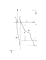
- the graph shown in FIG. 2 shows the change in voltage Vmot when the relay switch 12 is fixed and when the rotating shaft of the motor 14 is rotated by an external force.
- the vertical axis indicates the voltage Vmot
- the horizontal axis indicates time.
- the control device 20 controls the relay switch 12 and the discharge switch 16 to be in an off state.
- a waveform W1 indicates a change in the voltage Vmot when the relay switch 12 is fixed in the ON state.
- a waveform W1 shows a change in the voltage Vmot when the rotation shaft of the motor 14 is rotated by an external force while the relay switch 12 is in a normal state.
- the motorcycle gear is set to the back (reverse), and the control device 20 turns off the relay switch 12 and the discharge switch 16.
- the relay switch 12 is fixed in the ON state, the voltage of the DC power supply 11 is supplied to the node N2 via the relay switch 12 as shown by the waveform W1, and the voltage Vmot is a threshold value. Larger than B. In this case, the determination processing unit 234 of the control device 20 determines that the relay switch 12 is abnormal (the relay switch 12 is fixed).
- the voltage Vmot is less than the threshold A as shown by the waveform W2. Further, for example, when a motorcycle moves backward on a hill due to its own weight, the voltage Vmot gradually increases due to an electromotive force generated by rotating the rotating shaft of the motor 14 by an external force, as indicated by a waveform W1 or a waveform W2.
- the determination processing unit 234 In the waveform W2 at time T2, when the voltage Vmot reaches the threshold value A, the determination processing unit 234 starts measuring the predetermined period TR1. In the waveform W2 at time T3 reaching the predetermined period TR1, the voltage Vmot is less than the threshold value B. Using the change characteristic (electromotive force characteristic) of the voltage Vmot, the determination processing unit 234 determines that the relay switch 12 is used when the voltage Vmot becomes equal to or higher than the threshold value B until the time T3 when the predetermined time period TR1 is reached. Is abnormal (the relay switch 12 is fixed).
- the determination processing unit 234 determines that the relay switch 12 is normal when the voltage Vmot is less than the threshold value B at the time T3 when the predetermined period TR1 is reached, and the change in the voltage Vmot is caused by the rotation of the motor 14 due to an external force. It is determined that the shaft is caused by the rotated electromotive force.
- the predetermined period TR1 is a period after the voltage Vmot becomes equal to or higher than the threshold value A.
- the predetermined period TR1 is determined based on the electromotive force characteristic of the motor 14 when the maximum external force is applied to the rotating shaft of the motor 14. .
- the predetermined period TR1 is set based on the time (period) until the voltage Vmot reaches the threshold value B from the threshold value A, assuming, for example, the maximum slope of the slope. That is, the predetermined period TR1 is set shorter than the time (period) until the voltage Vmot reaches the threshold value B from the threshold value A.
- the determination region R ⁇ b> 1 is a region that is less than the threshold A, and is, for example, a pause region that indicates a region where the driving of the motor 14 is stopped.
- the determination region R2 is a region that is equal to or greater than the threshold value A and less than the threshold value B.
- the determination region R2 is a determination region (determination region for slope retreat) that indicates a region in which the rotation shaft of the motor 14 is rotated by an external force.
- the determination region R3 is a region that is equal to or greater than the threshold value B, and is a fixed region that indicates a region where the relay switch 12 is fixed in the on state.
- the threshold A and the threshold B are voltages lower than the battery voltage Vbat.
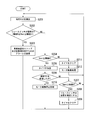
- the determination processing unit 234 of the control device 20 first determines whether or not the relay switch 12 is firmly fixed (step S101).
- the determination processing unit 234 determines whether or not the relay switch 12 is firmly fixed based on, for example, a determination flag of a storage unit (not shown).
- the determination processing unit 234 advances the process to step S102 when the fixing of the relay switch 12 is confirmed (step S101: YES).
- the determination process part 234 advances a process to step S103, when adhering of the relay switch 12 is not fixed (step S101: NO).
- step S102 the determination processing unit 234 transmits an alarm (warning) for stopping (stopping) the vehicle backward movement and prompting for repair. That is, the determination processing unit 234 determines that the relay switch 12 is abnormal (the switch is stuck), stops the motorcycle from moving backward, and transmits a warning that prompts the relay switch 12 to be repaired to the outside of the control device 20. .
- the control device 20 outputs a warning to, for example, a motorcycle user by using a warning lamp and a warning buzzer, for example.
- the determination processing unit 234 returns the process to step S101.
- step S103 the power supply voltage detection unit 231 of the control device 20 detects the battery voltage Vbat. That is, the power supply voltage detection unit 231 acquires the voltage value of the battery voltage Vbat detected by the voltage detection circuit 21 from the voltage detection circuit 21.
- the threshold setting unit 232 of the control device 20 calculates the threshold A and the threshold B from the battery voltage Vbat (step S104). That is, the threshold setting unit 232 Based on the power supply voltage (battery voltage Vbat) detected by the power supply voltage detection unit 231 (voltage detection circuit 21), threshold A and threshold B for determining whether or not the relay switch 12 is abnormal are, for example, As shown in FIG. 2, the threshold A and the threshold B are set.
- the motor voltage detector 233 of the control device 20 detects the voltage Vmot (step S105). That is, the motor voltage detection unit 233 acquires the voltage value of the voltage (voltage Vmot) between the motor 14 and the relay switch 12 detected by the voltage detection circuit 22 from the voltage detection circuit 22.
- the determination processing unit 234 determines that the relay switch 12 is firmly fixed (step S106). That is, for example, the determination processing unit 234 sets the determination flag of the storage unit (not shown) to a state in which the relay switch 12 is not firmly fixed.
- the determination processing unit 234 determines whether or not the voltage Vmot is equal to or higher than the threshold value A (Vmot ⁇ threshold value A) (step S107). That is, the determination processing unit 234 determines whether or not the determination region R1 (less than the threshold value A) illustrated in FIG. If the voltage Vmot is equal to or higher than the threshold A (step S107: YES), the determination processing unit 234 advances the process to step S108. Moreover, the determination process part 234 advances a process to step S114, when the voltage Vmot is less than the threshold value A (step S107: NO).
- step S108 the determination processing unit 234 adds a timer. That is, the determination processing unit 234 adds a timer (not shown) and measures the time.
- the determination processing unit 234 determines whether or not the period TR1 has elapsed (step S109). For example, the determination processing unit 234 determines whether or not the above-described timer value has reached a value corresponding to the period TR1. If it is determined that the period TR1 has elapsed (step S109: YES), the determination processing unit 234 advances the process to step S113. Moreover, the determination process part 234 advances a process to step S110, when it determines with not having passed period TR1 (step S109: NO).
- step S110 the determination processing unit 234 determines whether or not the voltage Vmot is equal to or higher than the threshold value B (Vmot ⁇ threshold value B). For example, the determination processing unit 234 determines whether or not the determination region R2 illustrated in FIG. 2 (threshold A or more and less than threshold B). If the voltage Vmot is equal to or higher than the threshold value B (step S110: YES), the determination processing unit 234 advances the process to step S111. Moreover, the determination process part 234 determines with it being the determination area
- step S111 the determination processing unit 234 determines that the relay switch 12 is fixed. That is, the determination processing unit 234 determines that the detected voltage (voltage Vmot) has reached or exceeded the threshold value B within the predetermined period (period TR1) (in the determination region R3 in FIG. 2), and the relay switch 12 is abnormal ( It is determined that the relay switch 12 is fixed. For example, the determination processing unit 234 sets the determination flag of the storage unit (not shown) to a state in which the relay switch 12 is firmly fixed.
- step S112 the determination processing unit 234 clears the timer (step S112). Note that clearing the timer means, for example, setting an initial value in the timer. After the process of step S112, the determination processing unit 234 returns the process to step S101. In this case, in step S101, the determination processing unit 234 determines that the relay switch 12 is firmly fixed, and in step S102, transmits an alarm (warning) to stop (stop) the vehicle and to prompt repairs. To do.
- step S113 the control unit 23 of the control device 20 executes a motor drive stop process.
- the determination processing unit 234 reaches the predetermined period TR1
- the voltage Vmot is less than the threshold value B (the determination region R2 in FIG. 2), so that the relay switch 12 is normal and the change in the voltage Vmot is changed.
- the control part 23 performs the motor drive stop process which stops the drive of the motor 14.
- the discharge processing unit 235 of the control unit 23 controls the discharge switch 16 to be in an ON state as a motor drive stop process, and causes the discharge switch 16 to discharge the voltage Vmot to the ground (reference potential) through the resistor 15.
- the control unit 23 returns the process to step S101.
- step S114 the determination processing unit 234 clears the timer. That is, the determination processing unit 234 determines that the voltage Vmot is in the determination region R1 shown in FIG. 2, and clears the timer.
- the control part 23 performs a motor drive process (step S115). That is, the control unit 23 executes a motor drive process that controls the drive of the motor 14. After the process of step S115, the control unit 23 returns the process to step S101.
- step S105 corresponds to the motor voltage detection step
- step S106 corresponds to the determination step
- step S103 corresponds to a power supply voltage detection step
- step S104 corresponds to a threshold setting step.
- the control method according to the present embodiment includes the motor 14 driven by the power supplied from the DC power supply 11, and the relay switch 12 (switch element) that controls the supply of power for driving the motor 14. It is the control method which the control apparatus 20 which controls the motor drive system 1 provided with performs.
- the control method according to the present embodiment includes a motor voltage detection step and a determination step.
- the motor voltage detection step the motor voltage detection unit 233 detects the voltage (voltage Vmot) between the motor 14 and the relay switch 12.
- the determination processing unit 234 determines that the detection voltage (voltage Vmot) detected in the motor voltage detection step is within the predetermined period TR1 after the threshold A or higher (first threshold or higher).
- the detected voltage is due to an electromotive force due to an external force applied to the rotating shaft of the motor 14, or due to an abnormality of the relay switch 12 (for example, the switch element is fixed). Can be distinguished. Therefore, in the control method according to the present embodiment, it is possible to reduce erroneous detection that the case where the motor 14 is rotated by an external force is an abnormality of the relay switch 12, and it is possible to accurately determine the abnormality of the relay switch 12.
- the determination processing unit 234 determines that the detection voltage (voltage Vmot) is due to an abnormality in the relay switch 12 when the detection voltage is equal to or higher than the threshold value B within the predetermined period TR1. Judge that there is. In the determination step, the determination processing unit 234 rotates the rotating shaft of the motor 14 by the external force of the detection voltage (voltage Vmot) when the detection voltage (voltage Vmot) does not reach the threshold value B within the predetermined period TR1. It is determined that this is due to the electromotive force.
- the control method according to the present embodiment can accurately determine abnormality of the relay switch 12 (for example, sticking of the switch) by a simple method.
- the detection voltage (voltage Vmot) is immediately set to the threshold value B depending on the state of the relay switch 12 being stuck, for example, in order to determine whether the relay switch 12 is abnormal after waiting for a predetermined period TR1. Even if it does not become the above, abnormality of relay switch 12 (for example, sticking of a switch) can be judged correctly.
- the control method according to the present embodiment includes a power supply voltage detection step and a threshold setting step.
- the power supply voltage detection step the power supply voltage detection unit 231 detects the voltage of the DC power supply 11.
- the threshold setting step the threshold setting unit 232 sets a threshold B for determining whether or not the relay switch 12 is abnormal based on the power supply voltage (battery voltage Vbat) detected in the power supply voltage detection step. .
- the control method according to the present embodiment can appropriately set the threshold B corresponding to the voltage of the DC power supply 11. Therefore, the control method according to the present embodiment can accurately determine abnormality of the relay switch 12 (for example, sticking of the switch) in response to a change in the voltage of the DC power supply 11.
- the predetermined period TR1 is determined based on the electromotive force characteristics of the motor 14 when a maximum external force (for example, an external force due to the maximum inclination of the hill) is applied to the rotation shaft of the motor 14.
- a maximum external force for example, an external force due to the maximum inclination of the hill
- the control method according to the present embodiment can appropriately set the predetermined period TR1 according to the electromotive force characteristics of the motor 14.
- control device 20 includes a motor drive system 1 including a motor 14 driven by electric power supplied from the DC power supply 11 and a relay switch 12 that controls supply of electric power for driving the motor 14. It is a control device to control.
- the control device 20 according to the present embodiment includes a motor voltage detection unit 233 and a determination processing unit 234 (determination unit).
- the motor voltage detector 233 detects a voltage (voltage Vmot) between the motor 14 and the relay switch 12.
- the determination processing unit 234 detects the detection voltage (voltage Vmot) detected by the motor voltage detection unit 233 within a predetermined period TR1 after the detection voltage (voltage Vmot) is equal to or higher than the threshold A (first threshold or higher).
- the control device 20 can reduce erroneous detection of the relay switch 12 being abnormal when the motor 14 is rotated by an external force, as in the control method according to the present embodiment described above. And the abnormality of the relay switch 12 can be accurately determined.
- the present embodiment is a modification of the first embodiment.
- the upper limit value (threshold value C) of the voltage Vmot is set, and the threshold value A and the threshold value B are set for the DC power supply 11. It is different from the first embodiment in that it is fixed regardless of the voltage (battery voltage Vbat).
- the configurations of the motor drive system 1 and the control device 20 according to the present embodiment are basically the same as those of the first embodiment, but the voltage detection circuit 21, the power supply voltage detection unit 231 and the threshold setting unit 232 are included. You do not have to prepare.
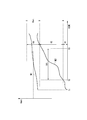
- the graph shown in FIG. 4 is basically the same as the graph shown in FIG. 2 described above, except that a threshold C is set.
- the threshold value C (third threshold value) is set to a voltage that is higher than the threshold value B (second threshold value) and the voltage (battery voltage Vbat) of the DC power supply 11 and that determines that the output of the DC power supply 11 is normal.
- the threshold value C is, for example, a voltage value obtained by adding a predetermined voltage for a margin to the upper limit value of the output voltage of the DC power supply 11 (battery).
- the determination processing unit 234 determines that the relay switch 12 is abnormal when the detection voltage (voltage Vmot) is equal to or higher than the threshold value B and lower than or equal to the threshold value C within the predetermined period TR1. Is determined. Further, when the detection voltage (voltage Vmot) is larger than the threshold C, the determination processing unit 234 may determine that the DC power supply 11 is abnormal, for example.
- the motor voltage detection unit 233 of the control device 20 first detects the voltage Vmot (step S201). That is, the motor voltage detection unit 233 acquires the voltage value of the voltage (voltage Vmot) between the motor 14 and the relay switch 12 detected by the voltage detection circuit 22 from the voltage detection circuit 22.
- the determination processing unit 234 of the control device 20 determines whether or not the relay switch 12 is fixed (step S202). For example, the determination processing unit 234 determines whether or not the detection voltage (voltage Vmot) detected by the motor voltage detection unit 233 is greater than or equal to the threshold value B and less than or equal to the threshold value C (threshold value B ⁇ Vmot ⁇ threshold value C). To do. If the voltage Vmot is greater than or equal to the threshold value B and less than or equal to the threshold value C (step S202: YES), the determination processing unit 234 advances the process to step S203. Moreover, the determination process part 234 advances a process to step S204, when the voltage Vmot is less than the threshold value B or larger than the threshold value C (step S202: NO).
- step S203 the determination processing unit 234 transmits an alarm (warning) for stopping (stopping) the vehicle from moving backward and urging repairs. That is, the determination processing unit 234 determines that the relay switch 12 is abnormal (switch is stuck), and stops the motorcycle from moving backward. Then, the determination processing unit 234 transmits a warning for prompting the relay switch 12 to be repaired to the outside of the control device 20.
- the control device 20 outputs a warning to, for example, a motorcycle user by using a warning lamp and a warning buzzer, for example.
- the determination processing unit 234 returns the process to step S201.
- step S204 to step S212 is the same as the processing from step S107 to step S115 shown in FIG. 3 described above, the description thereof is omitted here.
- step S201 corresponds to the motor voltage detection step
- step S204 corresponds to the determination step.
- the threshold value C (third threshold value) that is higher than the threshold value B (second threshold value) and the voltage (voltage Vbat) of the DC power supply 11 and is determined to be normal. ) Is stipulated. Then, in the determination step, the determination processing unit 234 determines that the relay switch when the detection voltage (voltage Vmot) is equal to or higher than the threshold value B and lower than or equal to the threshold value C (lower than the third threshold value) within the predetermined period TR1. 12 is determined to be abnormal.
- control method and the control device 20 according to the present embodiment can reduce erroneous detection of the relay switch 12 being abnormal when the motor 14 is rotated by an external force, as in the first embodiment. And the abnormality of the relay switch 12 can be accurately determined. Further, the control method and the control device 20 according to the present embodiment can distinguish between the abnormality of the relay switch 12 and the abnormality of the output voltage of the DC power supply 11 by using the threshold value C.
- the motor drive system 1 has been described as an example in which the motor 14 is a DC motor.
- the motor drive system 1a according to the present embodiment is applied to an AC motor.
- the motor drive system 1 a includes a DC power supply 11, a relay switch 12, a resistor 15, a motor 14 a, a discharge switch 16, an inverter unit 17, and a control device 20.
- the motor drive system 1a according to the present embodiment is different from the first embodiment in that an inverter unit 17 is provided instead of the resistor 13 and a motor 14a is provided instead of the motor 14.
- the motor 14 a is, for example, a three-phase AC motor, and is driven by electric power supplied from the DC power supply 11.
- the inverter unit 17 converts the DC power supplied from the DC power supply 11 from the DC power supply 11 via the relay switch 12 into a three-phase AC signal, and supplies it to the motor 14a.
- the motor 14a generates an electromotive force when, for example, the rotating shaft of the motor 14a rotates due to an external force, and a DC voltage is applied to the node N2 via the inverter unit 17. Further, the operation and control method of the control device 20 according to the present embodiment are the same as those in the first embodiment, and thus the description thereof is omitted.
- the motor drive system 1a includes the motor 14a that is a three-phase AC motor.
- the motor 14a is rotated by an external force as in the first embodiment. It is possible to reduce erroneous detection of a case as an abnormality of the relay switch 12.
- the DC power supply 11 is a storage battery such as a battery, and the example has been described.
- the present invention is not limited to this.
- a dynamo that generates DC power by rotation of an engine provided in the vehicle may be used, or another DC power supply unit may be used.
- the motor drive system 1 (1a) has been described by way of an example of a drive system for moving a motorcycle back as a vehicle by the motor 14 (14a).
- the present invention is not limited to this.
- the vehicle is not limited to a motorcycle, and may be another vehicle such as an automobile or an electric cart.
- the motor drive system 1 (1a) is not limited to the backward movement of the vehicle, as long as the electromotive force is generated by rotating the rotating shaft of the motor 14 (14a) by an external force. Good.
- an example of detecting the sticking of the ON state in the relay switch 12 when the motorcycle is stopped on a slope is taken as an example of a drive system for moving the motorcycle backward by the motor 14 (14a).
- the present invention is not limited to the case where the vehicle is stopped on a slope.
- the motorcycle may be stopped on a flat ground and the motorcycle may be backed by human power.
- the motor may be a direct current motor such as the motor 14 or an alternating current motor such as the motor 14a as in the first and second embodiments.
- the relay switch 12 that mechanically switches between the on state and the off state is applied as an example of the switch element has been described.
- a field effect transistor (FET) or the like has been described. It may be a semiconductor switch or another switch element.
- the motor drive system 1 (1a) has been described as including the resistor 15 and the discharge switch 16, but may be configured without the resistor 15 and the discharge switch 16.
- the control device 20 described above has a computer system inside.
- the processing process of the control device 20 described above is stored in a computer-readable recording medium in the form of a program, and the above-described processing is performed by the computer reading and executing this program.
- the computer-readable recording medium means a magnetic disk, a magneto-optical disk, a CD-ROM, a DVD-ROM, a semiconductor memory, or the like.
- the computer program may be distributed to the computer via a communication line, and the computer that has received the distribution may execute the program.
- control device 20 may be realized as an integrated circuit such as an LSI (Large Scale Integration). Each function described above may be individually made into a processor, or a part or all of them may be integrated into a processor. Further, the method of circuit integration is not limited to LSI, and may be realized by a dedicated circuit or a general-purpose processor. In addition, when an integrated circuit technology that replaces LSI appears due to the advancement of semiconductor technology, an integrated circuit based on the technology may be used.
- LSI Large Scale Integration
Landscapes
- Engineering & Computer Science (AREA)
- Power Engineering (AREA)
- Control Of Direct Current Motors (AREA)
- Control Of Electric Motors In General (AREA)
Abstract
制御方法は、直流電源から供給される電力により駆動されるモータと、当該モータを駆動する電力の供給を制御するスイッチ素子とを備えるモータ駆動システムを制御する制御装置が実行する制御方法であって、モータとスイッチ素子との間の電圧を検出するモータ電圧検出ステップと、モータ電圧検出ステップによって検出された検出電圧が、第1閾値以上になってからの所定の期間内に、当該検出電圧が、第1閾値より大きい第2閾値以上になったか否かに基づいて、検出電圧が、スイッチ素子の異常によるものか、外力によりモータの回転軸が回転した起電力によるものかを判定する判定ステップとを含む。
Description
本発明は、制御方法、及び制御装置に関する。
近年、バッテリなどの直流電源から供給される電力により駆動されるモータと、当該モータを駆動する電力の供給を制御するスイッチ素子とを備えるモータ駆動システムが普及している。このようなモータ駆動システムを制御する技術として、スイッチ素子とモータとの間の電圧を検出し、検出した検出電圧に基づいて、スイッチ素子の異常(例えば、短絡故障など)を判定する技術が知られている(例えば、特許文献1を参照)。
しかしながら、例えば、車両を後退させるためのモータ駆動システムのように、モータの回転軸に車輪などが接続され外力が掛かる場合には、坂道などに停車した後に、重力等によって車輪が回転するとモータに起電力が発生する。そのため、上述した従来技術では、この起電力の発生により検出電圧が変化するため、例えば、車両が坂道などに停車した後に、重力等の外力により車輪が回転した場合と、スイッチ素子の異常である場合とを区別することが困難であった。すなわち、上述した従来技術では、検出電圧が、モータの回転軸に加えられた外力による起電力によるものか、スイッチ素子の異常によるものかを区別できずに、スイッチ素子の異常を正確に判定できない場合があった。
本発明は、上記問題を解決すべくなされたもので、その目的は、モータを駆動する電力の供給を制御するスイッチ素子の異常を正確に判定することができる制御方法、及び制御装置を提供することにある。
上記問題を解決するために、本発明の一態様は、直流電源から供給される電力により駆動されるモータと、当該モータを駆動する電力の供給を制御するスイッチ素子とを備えるモータ駆動システムを制御する制御装置が実行する制御方法であって、前記モータと前記スイッチ素子との間の電圧を検出するモータ電圧検出ステップと、前記モータ電圧検出ステップによって検出された検出電圧が、第1閾値以上になってからの所定の期間内に、当該検出電圧が、前記第1閾値より大きい第2閾値以上になったか否かに基づいて、前記検出電圧が、前記スイッチ素子の異常によるものか、外力により前記モータの回転軸が回転した起電力によるものかを判定する判定ステップとを含む制御方法である。
また、本発明の一態様は、上記の制御方法において、前記判定ステップにおいて、前記検出電圧が前記所定の期間内に前記第2閾値以上になった場合に、前記検出電圧が前記スイッチ素子の異常によるものであると判定し、前記検出電圧が前記所定の期間内に前記第2閾値に達していない場合に、前記検出電圧が外力により前記モータの回転軸が回転した起電力によるものであると判定するようにしてもよい。
また、本発明の一態様は、上記の制御方法において、前記直流電源の電圧を検出する電源電圧検出ステップと、前記電源電圧検出ステップによって検出された電源電圧に基づいて、前記スイッチ素子が異常であるか否かを判定するための前記第2閾値を設定する閾値設定ステップとを含むようにしてもよい。
また、本発明の一態様は、上記の制御方法において、前記所定の期間は、前記モータの回転軸に最大外力が掛かった際の前記モータの起電力特性に基づいて定められるようにしてもよい。
また、本発明の一態様は、上記の制御方法において、前記第2閾値及び前記直流電源の電圧より高く、前記直流電源の出力が正常であると判定される第3閾値が定められており、前記判定ステップにおいて、前記所定の期間内に、前記検出電圧が、前記第2閾値以上、且つ、前記第3閾値以下になった場合に、前記スイッチ素子が異常であると判定するようにしてもよい。
また、本発明の一態様は、直流電源から供給される電力により駆動されるモータと、当該モータを駆動する電力の供給を制御するスイッチ素子とを備えるモータ駆動システムを制御する制御装置であって、前記モータと前記スイッチ素子との間の電圧を検出するモータ電圧検出部と、前記モータ電圧検出ステップによって検出された検出電圧が、第1閾値以上になってからの所定の期間内に、当該検出電圧が、前記第1閾値より大きい第2閾値以上になったか否かに基づいて、前記検出電圧が、前記スイッチ素子の異常によるものか、外力により前記モータの回転軸が回転した起電力によるものかを判定する判定部とを備える制御装置である。
本発明によれば、直流電源から供給される電力により駆動されるモータと、当該モータを駆動する電力の供給を制御するスイッチ素子とを備えるモータ駆動システムにおいて、制御装置は、モータとスイッチ素子との間の電圧を検出した検出電圧が、第1閾値以上になってからの所定の期間内に、当該検出電圧が、第1閾値より大きい第2閾値以上になったか否かに基づいて、当該検出電圧が、スイッチ素子の異常によるものか、外力によりモータの回転軸が回転した起電力によるものかを判定する。これにより、検出電圧がモータの回転軸に加えられた外力による起電力によるものか、スイッチ素子の異常によるものかを区別できるため、外力によりモータが回転した場合をスイッチ素子の異常であると誤検出することを防止することができ、スイッチ素子の異常を正確に判定できる。
以下、本発明の一実施形態による制御装置、及び制御方法について、図面を参照して説明する。
[第1の実施形態]
図1に示すように、モータ駆動システム1は、直流電源11と、リレースイッチ12と、抵抗(13、15)と、モータ14と、放電スイッチ16と、制御装置20とを備える。本実施形態において、モータ駆動システム1は、一例として、車両(例えば、オートバイなど)をモータ14により後退させるための駆動システムとして説明する。
図1に示すように、モータ駆動システム1は、直流電源11と、リレースイッチ12と、抵抗(13、15)と、モータ14と、放電スイッチ16と、制御装置20とを備える。本実施形態において、モータ駆動システム1は、一例として、車両(例えば、オートバイなど)をモータ14により後退させるための駆動システムとして説明する。
直流電源11は、例えば、バッテリなどの蓄電池であり、モータ14を駆動するための直流電力を供給する。直流電源11は、電源供給線であるノードN1を介して、リレースイッチ12に接続されている。
リレースイッチ12(スイッチ素子の一例)は、モータ14を駆動する電力の供給を制御するスイッチであり、直流電源11と、抵抗13との間に接続されている。リレースイッチ12は、制御装置20から出力される制御信号により、オン状態(導通状態)と、オフ状態(非導通状態)とが切り替えられる。
抵抗13は、リレースイッチ12とモータ14との間に接続され、リレースイッチ12を介して直流電源11からの直流電力をモータ14に供給する。
モータ14は、例えば、直流モータであり、直流電源11から供給される電力により駆動される。モータ14は、ノードN2を介して抵抗13と接続されている。また、モータ14の回転軸(不図示)には、不図示の車輪(例えば、オートバイの車輪)が接続されている。モータ14は、回転軸を回転させることにより、例えば、オートバイを後退させる。また、モータ14は、例えば、オートバイが坂道に停車した後に、重力等によって車輪が回転すると、当該車輪の回転が回転軸に伝わり、起電力を発生し、ノードN2に電圧が印加される。
抵抗15は、ノードN2と放電スイッチ16との間に接続され、放電スイッチ16がオン状態になった際に、ノードN2から放電される電流を制限する。
放電スイッチ16は、抵抗15の一端と、グランド(基準電位の一例)との間に接続され、抵抗15を介して、ノードN2の電圧をグランドに放電させる。放電スイッチ16は、制御装置20から出力される制御信号により、オン状態と、オフ状態とが切り替えられる。
制御装置20は、モータ駆動システム1を制御する。制御装置20は、例えば、リレースイッチ12と、放電スイッチ16とのそれぞれに、制御信号を出力し、各スイッチのオン状態とオフ状態とを切り替える制御を行う。また、制御装置20は、ノードN1の電圧(Vbat)及びノードN2の電圧(Vmot)を検出し、例えば、直流電源11の異常や、リレースイッチ12の異常などを判定する。
また、制御装置20は、電圧検出回路(21、22)と、制御部23とを備える。
また、制御装置20は、電圧検出回路(21、22)と、制御部23とを備える。
電圧検出回路21は、ノードN1の電圧であるバッテリ電圧Vbat(直流電源11の電圧)を検出する。電圧検出回路21は、バッテリ電圧Vbatを検出し、例えば、バッテリ電圧Vbatの電圧値を制御部23に出力する。
電圧検出回路22は、ノードN2の電圧である電圧Vmot(モータ14とリレースイッチ12との間の電圧)を検出する。電圧検出回路22は、電圧Vmotを検出し、例えば、電圧Vmotの電圧値を制御部23に出力する。
制御部23は、例えば、CPU(Central Processing Unit)などを含むプロセッサであり、制御装置20を統括的に制御する。制御部23は、例えば、電源電圧検出部231と、閾値設定部232と、モータ電圧検出部233と、判定処理部234と、放電処理部235とを備える。
電源電圧検出部231は、直流電源11の電圧を検出する。すなわち、電源電圧検出部231は、電圧検出回路21によって検出されたバッテリ電圧Vbatの電圧値を、電圧検出回路21から取得する。
閾値設定部232は、電源電圧検出部231(電圧検出回路21)によって検出された電源電圧(バッテリ電圧Vbat)に基づいて、リレースイッチ12が異常であるか否かを判定するための閾値A(第1閾値)及び閾値B(第2閾値)を設定する。なお、閾値A及び閾値Bの詳細については、図2を参照して後述する。閾値設定部232は、例えば、バッテリ電圧Vbatの所定の割合(所定の係数を積算すること)により、閾値A及び閾値Bを設定するようにしてもよい。
モータ電圧検出部233は、モータ14とリレースイッチ12との間の電圧(電圧Vmot)を検出する。すなわち、モータ電圧検出部233は、電圧検出回路22によって検出された電圧Vmotの電圧値を、電圧検出回路22から取得する。
判定処理部234(判定部の一例)は、モータ電圧検出部233によって検出された検出電圧(電圧Vmot)と、閾値設定部232によって設定された閾値A及び閾値Bとに基づいて、リレースイッチ12の異常や、モータ14の状態を判定する。判定処理部234は、例えば、外力によりモータ14の回転軸が回転した起電力による電圧Vmotの変化(起電力特性)に基づいて、リレースイッチ12の異常であるか否かを判定する。ここで、リレースイッチ12の異常とは、例えば、リレースイッチ12がオン状態に固定されるスイッチの固着(短絡故障)である。
具体的に、判定処理部234は、検出電圧(電圧Vmot)が、閾値A以上になってからの所定の期間(図2の期間TR1を参照)内に、当該検出電圧が、閾値Aより大きい閾値B以上になったか否かに基づいて、検出電圧(電圧Vmot)が、リレースイッチ12の異常によるものか、外力によりモータ14の回転軸が回転した起電力によるものかを判定する。判定処理部234は、例えば、検出電圧(電圧Vmot)が所定の期間(期間TR1)内に閾値B以上になった場合に、検出電圧(電圧Vmot)がリレースイッチ12の異常によるものであると判定する。また、判定処理部234は、例えば、検出電圧(電圧Vmot)が所定の期間(期間TR1)内に閾値Bに達していない場合に、検出電圧(電圧Vmot)が外力によりモータ14の回転軸が回転した起電力によるものであると判定する。
ここで、外力によりモータ14の回転軸が回転した起電力とは、例えば、オートバイが、前輪を坂道の上に向けて停止した後に、オートバイの自重(重力)により、オートバイが坂道を後退し、モータ14の回転軸が回転して発生した起電力である。なお、判定処理部234による判定処理の詳細については、図2及び図3を参照して後述する。
放電処理部235は、判定処理部234によって、検出電圧(電圧Vmot)が、外力によりモータ14の回転軸が回転した起電力によるものであると判定された場合に、モータ14とリレースイッチ12との間の電圧(電圧Vmot)を、放電スイッチ16によってグランド(基準電位)に放電させる。すなわち、放電処理部235は、例えば、オートバイの自重(重力)により、オートバイが坂道を後退した場合に、放電スイッチ16をオン状態に制御し、抵抗15を介して、電圧Vmot(モータ14の回転軸が回転した起電力)を放電する。
次に、図面を参照して、本実施形態による制御装置20の動作について説明する。
まず、図2を参照して、本実施形態における制御装置20によるリレースイッチ12の異常判定処理の詳細について説明する。
まず、図2を参照して、本実施形態における制御装置20によるリレースイッチ12の異常判定処理の詳細について説明する。
図2に示すグラフは、リレースイッチ12が固着した場合と、外力によりモータ14の回転軸が回転した場合との電圧Vmotの変化を示している。このグラフにおいて、縦軸は、電圧Vmotを示し、横軸は、時間を示している。なお、このグラフにおいて、制御装置20は、リレースイッチ12及び放電スイッチ16をオフ状態に制御しているものとする。
また、図2のグラフにおいて、波形W1は、リレースイッチ12がオン状態に固着した場合の電圧Vmotの変化を示している。また、波形W1は、リレースイッチ12は正常な状態において、外力によりモータ14の回転軸が回転した場合の電圧Vmotの変化を示している。
時刻T1において、例えば、オートバイが坂道で前輪を坂道の上に向けて停車した後に、オートバイのギアがバック(後退)に設定され、制御装置20は、リレースイッチ12及び放電スイッチ16をオフ状態にする。この状態において、リレースイッチ12がオン状態に固着している場合には、波形W1に示すように、リレースイッチ12を介して、直流電源11の電圧がノードN2に供給され、電圧Vmotが、閾値Bより大きくなる。この場合、制御装置20の判定処理部234は、リレースイッチ12が異常である(リレースイッチ12が固着している)と判定する。
また、時刻T1において、リレースイッチ12が固着していない場合には、波形W2に示すように、電圧Vmotは、閾値A未満の電圧である。
また、例えば、オートバイが坂道を自重により後退すると、波形W1又は波形W2に示すように、外力によりモータ14の回転軸が回転した起電力により、電圧Vmotは、徐々に上昇する。
また、例えば、オートバイが坂道を自重により後退すると、波形W1又は波形W2に示すように、外力によりモータ14の回転軸が回転した起電力により、電圧Vmotは、徐々に上昇する。
時刻T2の波形W2において、電圧Vmotが、閾値Aに達すると、判定処理部234は、所定の期間TR1の計時を開始する。所定の期間TR1に達する時刻T3の波形W2において、電圧Vmotは、閾値B未満である。この電圧Vmotの変化特性(起電力特性)を利用して、判定処理部234は、所定の期間TR1に達する時刻T3になるまでに、電圧Vmotが閾値B以上になった場合に、リレースイッチ12が異常である(リレースイッチ12が固着している)と判定する。
また、判定処理部234は、所定の期間TR1に達した時刻T3において、電圧Vmotが閾値B未満である場合に、リレースイッチ12が正常であり、電圧Vmotの変化が、外力によりモータ14の回転軸が回転した起電力によるものであると判定する。
ここで、所定の期間TR1は、電圧Vmotが閾値A以上になってからの期間であり、例えば、モータ14の回転軸に最大外力が掛かった際のモータ14の起電力特性に基づいて定められる。所定の期間TR1は、例えば、坂道の最大傾斜を想定して、電圧Vmotが閾値Aから閾値Bに達するまでの時間(期間)に基づいて設定される。すなわち、所定の期間TR1は、電圧Vmotが閾値Aから閾値Bに達するまでの時間(期間)よりも短く設定される。
また、図2において、判定領域R1は、閾値A未満の領域であり、例えば、モータ14の駆動を停止している領域を示す休止領域である。
また、判定領域R2は、閾値A以上、閾値B未満の領域であり、例えば、外力によりモータ14の回転軸が回転した領域を示す判定領域(坂道後退の判定領域)である。
また、判定領域R3は、閾値B以上の領域であり、リレースイッチ12がオン状態に固着した領域を示す固着領域である。
なお、図2に示すように、閾値A及び閾値Bは、バッテリ電圧Vbatよりも低い電圧である。
また、判定領域R2は、閾値A以上、閾値B未満の領域であり、例えば、外力によりモータ14の回転軸が回転した領域を示す判定領域(坂道後退の判定領域)である。
また、判定領域R3は、閾値B以上の領域であり、リレースイッチ12がオン状態に固着した領域を示す固着領域である。
なお、図2に示すように、閾値A及び閾値Bは、バッテリ電圧Vbatよりも低い電圧である。
次に、図3を参照して、本実施形態における制御装置20によるリレースイッチ12の異常判定処理の動作について説明する。
なお、図3に示す処理において、制御装置20は、初期状態として、リレースイッチ12及び放電スイッチ16をオフ状態に制御しているものとする。また、制御装置20は、初期状態において、リレースイッチ12の固着の判定を未確定にしているものとする。
なお、図3に示す処理において、制御装置20は、初期状態として、リレースイッチ12及び放電スイッチ16をオフ状態に制御しているものとする。また、制御装置20は、初期状態において、リレースイッチ12の固着の判定を未確定にしているものとする。
図3に示すように、制御装置20の判定処理部234は、まず、リレースイッチ12の固着が確定であるか否かを判定する(ステップS101)。判定処理部234は、例えば、記憶部(不図示)の判定フラグなどにより、リレースイッチ12の固着が確定であるか否かを判定する。判定処理部234は、リレースイッチ12の固着が確定である場合(ステップS101:YES)に、処理をステップS102に進める。また、判定処理部234は、リレースイッチ12の固着が確定でない場合(ステップS101:NO)に、処理をステップS103に進める。
ステップS102において、判定処理部234は、車両後退をストップ(停止)及び要修理を促すためのアラーム(警告)を送信する。すなわち、判定処理部234は、リレースイッチ12が異常(スイッチの固着)であると判定し、オートバイの後退を停止させ、リレースイッチ12の要修理を促す警告を、制御装置20の外部に送信する。制御装置20は、例えば、警告ランプ及び警告ブザーなどにより、例えば、オートバイの利用者などに警告を出力する。ステップS102の処理後に、判定処理部234は、処理をステップS101に戻す。
また、ステップS103において、制御装置20の電源電圧検出部231は、バッテリ電圧Vbatを検出する。すなわち、電源電圧検出部231は、電圧検出回路21によって検出されたバッテリ電圧Vbatの電圧値を、電圧検出回路21から取得する。
次に、制御装置20の閾値設定部232は、バッテリ電圧Vbatにより閾値A及び閾値Bを算出する(ステップS104)。すなわち、閾値設定部232は、
電源電圧検出部231(電圧検出回路21)によって検出された電源電圧(バッテリ電圧Vbat)に基づいて、リレースイッチ12が異常であるか否かを判定するための閾値A及び閾値Bを、例えば、図2に示すように算出して、当該閾値A及び閾値Bを設定する。
電源電圧検出部231(電圧検出回路21)によって検出された電源電圧(バッテリ電圧Vbat)に基づいて、リレースイッチ12が異常であるか否かを判定するための閾値A及び閾値Bを、例えば、図2に示すように算出して、当該閾値A及び閾値Bを設定する。
次に、制御装置20のモータ電圧検出部233は、電圧Vmotを検出する(ステップS105)。すなわち、モータ電圧検出部233は、電圧検出回路22によって検出されたモータ14とリレースイッチ12との間の電圧(電圧Vmot)の電圧値を、電圧検出回路22から取得する。
次に、判定処理部234は、リレースイッチ12の固着の判定を未確定にする(ステップS106)。すなわち、判定処理部234は、例えば、記憶部(不図示)の判定フラグを、一旦、リレースイッチ12の固着が確定していない状態に設定する。
次に、判定処理部234は、電圧Vmotが閾値A以上(Vmot≧閾値A)であるか否かを判定する(ステップS107)。すなわち、判定処理部234は、図2に示す判定領域R1(閾値A未満)であるか否かを判定する。判定処理部234は、電圧Vmotが閾値A以上である場合(ステップS107:YES)に、処理をステップS108に進める。また、判定処理部234は、電圧Vmotが閾値A未満である場合(ステップS107:NO)に、処理をステップS114に進める。
ステップS108において、判定処理部234は、タイマを加算する。すなわち、判定処理部234は、不図示のタイマを加算して計時する。
次に、判定処理部234は、期間TR1を経過したか否かを判定する(ステップS109)。判定処理部234は、例えば、上述したタイマの値が、期間TR1に対応する値に達したか否かを判定する。判定処理部234は、期間TR1を経過したと判定した場合(ステップS109:YES)に、処理をステップS113に進める。また、判定処理部234は、期間TR1を経過していないと判定した場合(ステップS109:NO)に、処理をステップS110に進める。
次に、判定処理部234は、期間TR1を経過したか否かを判定する(ステップS109)。判定処理部234は、例えば、上述したタイマの値が、期間TR1に対応する値に達したか否かを判定する。判定処理部234は、期間TR1を経過したと判定した場合(ステップS109:YES)に、処理をステップS113に進める。また、判定処理部234は、期間TR1を経過していないと判定した場合(ステップS109:NO)に、処理をステップS110に進める。
ステップS110において、判定処理部234は、電圧Vmotが閾値B以上(Vmot≧閾値B)であるか否かを判定する。判定処理部234は、例えば、図2に示す判定領域R2(閾値A以上、閾値B未満)であるか否かを判定する。判定処理部234は、電圧Vmotが閾値B以上である場合(ステップS110:YES)に、処理をステップS111に進める。また、判定処理部234は、電圧Vmotが閾値B未満である場合(ステップS110:NO)に、判定領域R2であると判定し、処理をステップS101に戻す。
ステップS111において、判定処理部234は、リレースイッチ12の固着を確定にする。すなわち、判定処理部234は、検出電圧(電圧Vmot)が所定の期間(期間TR1)内に閾値B以上になった(図2の判定領域R3である)と判定し、リレースイッチ12が異常(リレースイッチ12の固着)であると判定する。判定処理部234は、例えば、記憶部(不図示)の判定フラグを、リレースイッチ12の固着が確定している状態に設定する。
次に、判定処理部234は、タイマをクリアする(ステップS112)。なお、タイマをクリアするとは、例えば、タイマに初期値を設定することを意味する。ステップS112の処理後に、判定処理部234は、処理をステップS101に戻す。この場合、ステップS101において、判定処理部234は、リレースイッチ12の固着が確定であると判定し、ステップS102において、車両後退をストップ(停止)及び要修理を促すためのアラーム(警告)を送信する。
また、ステップS113において、制御装置20の制御部23は、モータ駆動停止処理を実行する。この場合、判定処理部234は、所定の期間TR1に達した際に、電圧Vmotが閾値B未満(図2の判定領域R2)であるため、リレースイッチ12が正常であり、電圧Vmotの変化が、外力によりモータ14の回転軸が回転した起電力によるものであると判定する。そして、制御部23は、モータ14の駆動を停止するモータ駆動停止処理を実行する。例えば、制御部23の放電処理部235は、モータ駆動停止処理として、放電スイッチ16をオン状態に制御し、放電スイッチ16によって、抵抗15を介して電圧Vmotをグランド(基準電位)に放電させる。ステップS113の処理後に、制御部23は、処理をステップS101に戻す。
また、ステップS114において、判定処理部234は、タイマをクリアする。すなわち、判定処理部234は、電圧Vmotが図2に示す判定領域R1であると判定し、タイマをクリアする。
次に、制御部23は、モータ駆動処理を実行する(ステップS115)。すなわち、制御部23は、モータ14の駆動を制御するモータ駆動処理を実行する。ステップS115の処理後に、制御部23は、処理をステップS101に戻す。
次に、制御部23は、モータ駆動処理を実行する(ステップS115)。すなわち、制御部23は、モータ14の駆動を制御するモータ駆動処理を実行する。ステップS115の処理後に、制御部23は、処理をステップS101に戻す。
上述した図3に示す処理において、ステップS105の処理がモータ電圧検出ステップに対応し、ステップS106からステップS111までの処理が、判定ステップに対応する。また、ステップS103の処理が、電源電圧検出ステップに対応し、ステップS104の処理が、閾値設定ステップに対応する。
以上説明したように、本実施形態による制御方法は、直流電源11から供給される電力により駆動されるモータ14と、当該モータ14を駆動する電力の供給を制御するリレースイッチ12(スイッチ素子)とを備えるモータ駆動システム1を制御する制御装置20が実行する制御方法である。本実施形態による制御方法は、モータ電圧検出ステップと、判定ステップとを含む。モータ電圧検出ステップにおいて、モータ電圧検出部233が、モータ14とリレースイッチ12との間の電圧(電圧Vmot)を検出する。そして、判定ステップにおいて、判定処理部234は、モータ電圧検出ステップによって検出された検出電圧(電圧Vmot)が、閾値A以上(第1閾値以上)になってからの所定の期間TR1内に、当該検出電圧(電圧Vmot)が、閾値Aより大きい閾値B以上(第2閾値以上)になったか否かに基づいて、検出電圧(電圧Vmot)が、リレースイッチ12の異常によるものか、外力によりモータ14の回転軸が回転した起電力によるものかを判定する。
これにより、本実施形態による制御方法では、検出電圧(電圧Vmot)がモータ14の回転軸に加えられた外力による起電力によるものか、リレースイッチ12の異常(例えば、スイッチ素子の固着)によるものかを区別できる。そのため、本実施形態による制御方法では、外力によりモータ14が回転した場合をリレースイッチ12の異常であると誤検出することを低減させることができ、リレースイッチ12の異常を正確に判定できる。
また、本実施形態では、判定ステップにおいて、判定処理部234は、検出電圧が所定の期間TR1内に閾値B以上になった場合に、検出電圧(電圧Vmot)がリレースイッチ12の異常によるものであると判定する。また、判定ステップにおいて、判定処理部234は、検出電圧(電圧Vmot)が所定の期間TR1内に閾値Bに達していない場合に、検出電圧(電圧Vmot)が外力によりモータ14の回転軸が回転した起電力によるものであると判定する。
これにより、本実施形態による制御方法は、簡易な手法により、リレースイッチ12の異常(例えば、スイッチの固着)を正確に判定できる。なお、本実施形態による制御方法では、所定の期間TR1待ってから、リレースイッチ12の異常を判定するため、例えば、リレースイッチ12の固着の状態により、検出電圧(電圧Vmot)がすぐに閾値B以上にならない場合であっても、リレースイッチ12の異常(例えば、スイッチの固着)を正確に判定することができる。
また、本実施形態による制御方法は、電源電圧検出ステップと、閾値設定ステップとを含む。電源電圧検出ステップにおいて、電源電圧検出部231は、直流電源11の電圧を検出する。閾値設定ステップにおいて、閾値設定部232は、電源電圧検出ステップによって検出された電源電圧(バッテリ電圧Vbat)に基づいて、リレースイッチ12が異常であるか否かを判定するための閾値Bを設定する。
これにより、本実施形態による制御方法は、直流電源11の電圧に対応して、閾値Bを適切に設定することができる。よって、本実施形態による制御方法は、直流電源11の電圧の変化に対応して、リレースイッチ12の異常(例えば、スイッチの固着)を正確に判定することができる。
これにより、本実施形態による制御方法は、直流電源11の電圧に対応して、閾値Bを適切に設定することができる。よって、本実施形態による制御方法は、直流電源11の電圧の変化に対応して、リレースイッチ12の異常(例えば、スイッチの固着)を正確に判定することができる。
また、本実施形態では、所定の期間TR1は、モータ14の回転軸に最大外力(例えば、坂道の最大傾斜による外力)が掛かった際のモータ14の起電力特性に基づいて定められる。
これにより、本実施形態による制御方法は、所定の期間TR1を、モータ14の起電力特性に応じて適切に設定することができる。
これにより、本実施形態による制御方法は、所定の期間TR1を、モータ14の起電力特性に応じて適切に設定することができる。
また、本実施形態による制御装置20は、直流電源11から供給される電力により駆動されるモータ14と、当該モータ14を駆動する電力の供給を制御するリレースイッチ12とを備えるモータ駆動システム1を制御する制御装置である。本実施形態による制御装置20は、モータ電圧検出部233と、判定処理部234(判定部)とを備える。モータ電圧検出部233は、モータ14とリレースイッチ12との間の電圧(電圧Vmot)を検出する。そして、判定処理部234は、モータ電圧検出部233によって検出された検出電圧(電圧Vmot)が、閾値A以上(第1閾値以上)になってからの所定の期間TR1内に、当該検出電圧(電圧Vmot)が、閾値A(第1閾値)より大きい閾値B以上(第2閾値以上)になったか否かに基づいて、検出電圧(電圧Vmot)が、リレースイッチ12の異常によるものか、外力によりモータ14の回転軸が回転した起電力によるものかを判定する。
これにより、本実施形態による制御装置20は、上述した本実施形態による制御方法と同様に、外力によりモータ14が回転した場合をリレースイッチ12の異常であると誤検出することを低減させることができ、リレースイッチ12の異常を正確に判定することができる。
これにより、本実施形態による制御装置20は、上述した本実施形態による制御方法と同様に、外力によりモータ14が回転した場合をリレースイッチ12の異常であると誤検出することを低減させることができ、リレースイッチ12の異常を正確に判定することができる。
[第2の実施形態]
次に、第2の実施形態による制御装置20、及び制御方法について説明する。
次に、第2の実施形態による制御装置20、及び制御方法について説明する。
本実施形態は、第1の実施形態の変形例であり、リレースイッチ12の異常の判定において、電圧Vmotの上限値(閾値C)を設定する点と、閾値A及び閾値Bを直流電源11の電圧(バッテリ電圧Vbat)によらずに、固定にした点が、第1の実施形態と異なる。
なお、本実施形態によるモータ駆動システム1及び制御装置20の構成は、基本的に、第1の実施形態と同様であるが、電圧検出回路21、電源電圧検出部231、及び閾値設定部232を備えなくでもよい。
なお、本実施形態によるモータ駆動システム1及び制御装置20の構成は、基本的に、第1の実施形態と同様であるが、電圧検出回路21、電源電圧検出部231、及び閾値設定部232を備えなくでもよい。
図4に示すグラフは、基本的には、上述した図2に示すグラフと同様であるが、閾値Cが設定されている点が異なる。
閾値C(第3閾値)には、閾値B(第2閾値)及び直流電源11の電圧(バッテリ電圧Vbat)より高く、直流電源11の出力が正常であると判定される電圧が定められている。閾値Cは、例えば、直流電源11(バッテリ)の出力電圧の上限値に、マージン分の所定の電圧を加算した電圧値である。
なお、本実施形態では、判定処理部234は、所定の期間TR1内に、検出電圧(電圧Vmot)が、閾値B以上、且つ、閾値C以下になった場合に、リレースイッチ12が異常であると判定する。また、判定処理部234は、検出電圧(電圧Vmot)が、閾値Cより大きい場合には、例えば、直流電源11が異常であると判定してもよい。
次に、図5を参照して、本実施形態における制御装置20によるリレースイッチ12の異常判定処理の動作について説明する。
なお、図5に示す処理において、制御装置20は、初期状態として、リレースイッチ12及び放電スイッチ16をオフ状態に制御しているものとする。
なお、図5に示す処理において、制御装置20は、初期状態として、リレースイッチ12及び放電スイッチ16をオフ状態に制御しているものとする。
図5に示すように、制御装置20のモータ電圧検出部233は、まず、電圧Vmotを検出する(ステップS201)。すなわち、モータ電圧検出部233は、電圧検出回路22によって検出されたモータ14とリレースイッチ12との間の電圧(電圧Vmot)の電圧値を、電圧検出回路22から取得する。
次に、制御装置20の判定処理部234は、リレースイッチ12の固着であるか否かを判定する(ステップS202)。判定処理部234は、例えば、モータ電圧検出部233によって検出された検出電圧(電圧Vmot)が、閾値B以上、且つ、閾値C以下(閾値B≦Vmot≦閾値C)であるか否かを判定する。判定処理部234は、電圧Vmotが、閾値B以上、且つ、閾値C以下である場合(ステップS202:YES)に、処理をステップS203に進める。また、判定処理部234は、電圧Vmotが、閾値B未満、又は、閾値Cより大きい場合(ステップS202:NO)に、処理をステップS204に進める。
ステップS203において、判定処理部234は、車両後退をストップ(停止)及び要修理を促すためのアラーム(警告)を送信する。すなわち、判定処理部234は、リレースイッチ12が異常(スイッチの固着)であると判定し、オートバイの後退を停止させる。そして、判定処理部234は、リレースイッチ12の要修理を促す警告を、制御装置20の外部に送信する。制御装置20は、例えば、警告ランプ及び警告ブザーなどにより、例えば、オートバイの利用者などに警告を出力する。ステップS203の処理後に、判定処理部234は、処理をステップS201に戻す。
また、ステップS204からステップS212までの処理は、上述した図3に示すステップS107からステップS115までの処理と同様であるため、ここではその説明を省略する。
なお、上述した図5に示す処理において、ステップS201の処理がモータ電圧検出ステップに対応し、ステップS202、ステップS204からステップS208までの処理が、判定ステップに対応する。
以上説明したように、本実施形態において、閾値B(第2閾値)及び直流電源11の電圧(電圧Vbat)より高く、直流電源11の出力が正常であると判定される閾値C(第3閾値)が定められている。そして、判定ステップにおいて、判定処理部234は、所定の期間TR1内に、検出電圧(電圧Vmot)が、閾値B以上、且つ、閾値C以下(第3閾値以下)になった場合に、リレースイッチ12が異常であると判定する。
これにより、本実施形態による制御方法及び制御装置20は、第1の実施形態と同様に、外力によりモータ14が回転した場合をリレースイッチ12の異常であると誤検出することを低減させることができ、リレースイッチ12の異常を正確に判定することができる。また、本実施形態による制御方法及び制御装置20は、閾値Cを用いることにより、リレースイッチ12の異常と、直流電源11の出力電圧の異常とを区別することができる。
[第3の実施形態]
次に、図6を参照して、第3の実施形態によるモータ駆動システム1a、制御装置20、及び制御方法について説明する。
上述した第1及び第2の実施形態において、モータ駆動システム1は、モータ14が直流モータである場合の一例を説明したが、本実施形態によるモータ駆動システム1aは、交流モータに適用した場合の一例について説明する。
図6に示すように、モータ駆動システム1aは、直流電源11と、リレースイッチ12と、抵抗15と、モータ14aと、放電スイッチ16と、インバータ部17と、制御装置20とを備える。
次に、図6を参照して、第3の実施形態によるモータ駆動システム1a、制御装置20、及び制御方法について説明する。
上述した第1及び第2の実施形態において、モータ駆動システム1は、モータ14が直流モータである場合の一例を説明したが、本実施形態によるモータ駆動システム1aは、交流モータに適用した場合の一例について説明する。
図6に示すように、モータ駆動システム1aは、直流電源11と、リレースイッチ12と、抵抗15と、モータ14aと、放電スイッチ16と、インバータ部17と、制御装置20とを備える。
なお、この図において、上述した図1と同一の構成には、同一の符号を付与して、その説明を省略する。
本実施形態によるモータ駆動システム1aは、抵抗13の代わりにインバータ部17を備え、モータ14の代わりにモータ14aを備える点が、第1の実施形態と異なる。
本実施形態によるモータ駆動システム1aは、抵抗13の代わりにインバータ部17を備え、モータ14の代わりにモータ14aを備える点が、第1の実施形態と異なる。
モータ14aは、例えば、3相交流モータであり、直流電源11から供給される電力により駆動される。
インバータ部17は、直流電源11からリレースイッチ12を介して、直流電源11から供給される直流電力を、3相交流信号に変換して、モータ14aに供給する。
インバータ部17は、直流電源11からリレースイッチ12を介して、直流電源11から供給される直流電力を、3相交流信号に変換して、モータ14aに供給する。
なお、モータ14aは、例えば、外力によりモータ14aの回転軸が回転した場合に、起電力を発生し、インバータ部17を介して、直流電圧がノードN2に印加される。
また、本実施形態による制御装置20の動作、及び制御方法は、第1の実施形態と同様であるので、その説明を省略する。
また、本実施形態による制御装置20の動作、及び制御方法は、第1の実施形態と同様であるので、その説明を省略する。
以上説明したように、本実施形態では、モータ駆動システム1aは、3相交流モータであるモータ14aを備えるが、制御装置20は、第1の実施形態と同様に、外力によりモータ14aが回転した場合をリレースイッチ12の異常であると誤検出することを低減させることができる。
なお、本発明は、上記の各実施形態に限定されるものではなく、本発明の趣旨を逸脱しない範囲で変更可能である。
例えば、上記の各実施形態において、直流電源11は、バッテリなどの蓄電池であり例を説明したが、これに限定されるものではない。例えば、車両が備えるエンジンの回転により直流電力を発電するダイナモであってもよいし、他の直流電力を供給する手段であってもよい。
例えば、上記の各実施形態において、直流電源11は、バッテリなどの蓄電池であり例を説明したが、これに限定されるものではない。例えば、車両が備えるエンジンの回転により直流電力を発電するダイナモであってもよいし、他の直流電力を供給する手段であってもよい。
また、上記の各実施形態において、モータ駆動システム1(1a)は、車両としてオートバイをモータ14(14a)により後退させるための駆動システムを一例として説明したが、これに限定されるものではない。例えば、車両は、オートバイに限定されるものではなく、自動車や電動カートなどの他の車両であってもよい。また、モータ駆動システム1(1a)は、外力によりモータ14(14a)の回転軸が回転して起電力が発生する構成であれば、車両の後退に限らず、他の駆動システムであってもよい。
また、上記の各実施形態において、オートバイをモータ14(14a)により後退させるための駆動システムを一例として、オートバイが坂道に停車している場合に、リレースイッチ12におけるオン状態の固着を検出する例を説明したが、坂道に停車している場合に限定されるものではない。例えば、オートバイが平地に停車していて、人力によりオートバイをバックさせるような場合であってもよい。
また、上述したように、モータは、第1、及び第2の実施形態のように、モータ14のような直流モータであってもよいし、モータ14aのような交流モータであってもよい。
また、上記の各実施形態において、スイッチ素子の一例として、機械的にオン状態とオフ状態とを切り替えるリレースイッチ12を適用する例を説明したが、FET(Field effect transistor;電界効果トランジスタ)などの半導体スイッチであってもよく、他のスイッチ素子であってもよい。
また、上記の各実施形態において、実施形態の一部の適用を除外してもよいし、各実施形態の一部を組み合わせて実施してもよい。例えば、上記の第2の実施形態において、閾値C(第3閾値)を適用する例を説明したが、第1の実施形態において、同様に、閾値Cを適用してもよい。また、上記の第2の実施形態において、閾値Cを適用しない形態であってもよい。
また、上記の第1及び第2の実施形態において、リレースイッチ12と、モータ14との間に抵抗13を配置する例を説明したが、これに限定されるものではなく、当該抵抗13を備えない形態であってもよい。
また、上記の各実施形態において、モータ駆動システム1(1a)は、抵抗15及び放電スイッチ16を備える例を説明したが、抵抗15及び放電スイッチ16を備えない形態であってもよい。
また、上記の各実施形態において、モータ駆動システム1(1a)は、抵抗15及び放電スイッチ16を備える例を説明したが、抵抗15及び放電スイッチ16を備えない形態であってもよい。
なお、上述の制御装置20は内部に、コンピュータシステムを有している。そして、上述した制御装置20の処理過程は、プログラムの形式でコンピュータ読み取り可能な記録媒体に記憶されており、このプログラムをコンピュータが読み出して実行することによって、上記処理が行われる。ここでコンピュータ読み取り可能な記録媒体とは、磁気ディスク、光磁気ディスク、CD-ROM、DVD-ROM、半導体メモリ等をいう。また、このコンピュータプログラムを通信回線によってコンピュータに配信し、この配信を受けたコンピュータが当該プログラムを実行するようにしてもよい。
また、上述した制御装置20が備える機能の一部又は全部を、LSI(Large Scale Integration)等の集積回路として実現してもよい。上述した各機能は個別にプロセッサ化してもよいし、一部、又は全部を集積してプロセッサ化してもよい。また、集積回路化の手法はLSIに限らず専用回路、又は汎用プロセッサで実現してもよい。また、半導体技術の進歩によりLSIに代替する集積回路化の技術が出現した場合、当該技術による集積回路を用いてもよい。
1、1a モータ駆動システム
11 直流電源
12 リレースイッチ
13、15 抵抗
14、14a モータ
16 放電スイッチ
17 インバータ部
20 制御装置
21、22 電圧検出回路
23 制御部
231 電源電圧検出部
232 閾値設定部
233 モータ電圧検出部
234 判定処理部
235 放電処理部
11 直流電源
12 リレースイッチ
13、15 抵抗
14、14a モータ
16 放電スイッチ
17 インバータ部
20 制御装置
21、22 電圧検出回路
23 制御部
231 電源電圧検出部
232 閾値設定部
233 モータ電圧検出部
234 判定処理部
235 放電処理部
Claims (6)
- 直流電源から供給される電力により駆動されるモータと、当該モータを駆動する電力の供給を制御するスイッチ素子とを備えるモータ駆動システムを制御する制御装置が実行する制御方法であって、
前記モータと前記スイッチ素子との間の電圧を検出するモータ電圧検出ステップと、
前記モータ電圧検出ステップによって検出された検出電圧が、第1閾値以上になってからの所定の期間内に、当該検出電圧が、前記第1閾値より大きい第2閾値以上になったか否かに基づいて、前記検出電圧が、前記スイッチ素子の異常によるものか、外力により前記モータの回転軸が回転した起電力によるものかを判定する判定ステップと
を含む制御方法。 - 前記判定ステップにおいて、前記検出電圧が前記所定の期間内に前記第2閾値以上になった場合に、前記検出電圧が前記スイッチ素子の異常によるものであると判定し、前記検出電圧が前記所定の期間内に前記第2閾値に達していない場合に、前記検出電圧が外力により前記モータの回転軸が回転した起電力によるものであると判定する
請求項1に記載の制御方法。 - 前記直流電源の電圧を検出する電源電圧検出ステップと、
前記電源電圧検出ステップによって検出された電源電圧に基づいて、前記スイッチ素子が異常であるか否かを判定するための前記第2閾値を設定する閾値設定ステップと
を含む請求項1又は請求項2に記載の制御方法。 - 前記所定の期間は、前記モータの回転軸に最大外力が掛かった際の前記モータの起電力特性に基づいて定められる
請求項1から請求項3のいずれか一項に記載の制御方法。 - 前記第2閾値及び前記直流電源の電圧より高く、前記直流電源の出力が正常であると判定される第3閾値が定められており、
前記判定ステップにおいて、前記所定の期間内に、前記検出電圧が、前記第2閾値以上、且つ、前記第3閾値以下になった場合に、前記スイッチ素子が異常であると判定する
請求項1から請求項4のいずれか一項に記載の制御方法。 - 直流電源から供給される電力により駆動されるモータと、当該モータを駆動する電力の供給を制御するスイッチ素子とを備えるモータ駆動システムを制御する制御装置であって、
前記モータと前記スイッチ素子との間の電圧を検出するモータ電圧検出部と、
前記モータ電圧検出部によって検出された検出電圧が、第1閾値以上になってからの所定の期間内に、当該検出電圧が、前記第1閾値より大きい第2閾値以上になったか否かに基づいて、前記検出電圧が、前記スイッチ素子の異常によるものか、外力により前記モータの回転軸が回転した起電力によるものかを判定する判定部と
を備える制御装置。
Priority Applications (2)
| Application Number | Priority Date | Filing Date | Title |
|---|---|---|---|
| PCT/JP2016/074811 WO2018037528A1 (ja) | 2016-08-25 | 2016-08-25 | 制御方法、及び制御装置 |
| JP2017502738A JP6205521B1 (ja) | 2016-08-25 | 2016-08-25 | 制御方法、及び制御装置 |
Applications Claiming Priority (1)
| Application Number | Priority Date | Filing Date | Title |
|---|---|---|---|
| PCT/JP2016/074811 WO2018037528A1 (ja) | 2016-08-25 | 2016-08-25 | 制御方法、及び制御装置 |
Publications (1)
| Publication Number | Publication Date |
|---|---|
| WO2018037528A1 true WO2018037528A1 (ja) | 2018-03-01 |
Family
ID=59969442
Family Applications (1)
| Application Number | Title | Priority Date | Filing Date |
|---|---|---|---|
| PCT/JP2016/074811 Ceased WO2018037528A1 (ja) | 2016-08-25 | 2016-08-25 | 制御方法、及び制御装置 |
Country Status (2)
| Country | Link |
|---|---|
| JP (1) | JP6205521B1 (ja) |
| WO (1) | WO2018037528A1 (ja) |
Families Citing this family (1)
| Publication number | Priority date | Publication date | Assignee | Title |
|---|---|---|---|---|
| KR20250082034A (ko) * | 2023-11-28 | 2025-06-09 | 삼성전자주식회사 | 진단 동작을 수행하는 웨어러블 장치 및 이의 동작 방법 |
Citations (3)
| Publication number | Priority date | Publication date | Assignee | Title |
|---|---|---|---|---|
| JP2006311633A (ja) * | 2005-04-26 | 2006-11-09 | Nissan Motor Co Ltd | 電動モータの制御装置及びその故障診断方法 |
| JP2011176935A (ja) * | 2010-02-24 | 2011-09-08 | Advics Co Ltd | モータ駆動装置 |
| JP2012222855A (ja) * | 2011-04-04 | 2012-11-12 | Denso Corp | モータ駆動装置 |
-
2016
- 2016-08-25 JP JP2017502738A patent/JP6205521B1/ja active Active
- 2016-08-25 WO PCT/JP2016/074811 patent/WO2018037528A1/ja not_active Ceased
Patent Citations (3)
| Publication number | Priority date | Publication date | Assignee | Title |
|---|---|---|---|---|
| JP2006311633A (ja) * | 2005-04-26 | 2006-11-09 | Nissan Motor Co Ltd | 電動モータの制御装置及びその故障診断方法 |
| JP2011176935A (ja) * | 2010-02-24 | 2011-09-08 | Advics Co Ltd | モータ駆動装置 |
| JP2012222855A (ja) * | 2011-04-04 | 2012-11-12 | Denso Corp | モータ駆動装置 |
Also Published As
| Publication number | Publication date |
|---|---|
| JPWO2018037528A1 (ja) | 2018-08-23 |
| JP6205521B1 (ja) | 2017-09-27 |
Similar Documents
| Publication | Publication Date | Title |
|---|---|---|
| JP5482055B2 (ja) | 電力供給制御装置 | |
| JP5282790B2 (ja) | 電子装置 | |
| JP5505730B2 (ja) | 故障情報伝達装置 | |
| US8044617B2 (en) | Motor control circuit and operation method thereof | |
| US10910979B2 (en) | Motor drive control device and motor drive control method | |
| JP2013229966A (ja) | 通電回路の保護装置 | |
| JP2016086578A (ja) | 放電制御装置、及び、これを備える電力変換装置 | |
| US9537433B2 (en) | Motor drive device | |
| JP5561197B2 (ja) | 電子装置 | |
| CN105450139A (zh) | 电动机驱动装置 | |
| JP6262931B2 (ja) | 通電回路の保護装置 | |
| CN104950238A (zh) | 换流器及其igbt驱动电路的故障检测方法和装置 | |
| JP2010058635A (ja) | バッテリ冷却装置 | |
| JP2009296826A (ja) | リレー制御装置 | |
| JP6205521B1 (ja) | 制御方法、及び制御装置 | |
| JP7013860B2 (ja) | モータ駆動装置 | |
| CN104168679B (zh) | 电磁炉及其放电方法 | |
| TWM664883U (zh) | 馬達驅動器之功率元件保護裝置 | |
| JP2005110429A5 (ja) | ||
| JP6844028B2 (ja) | 電力変換装置 | |
| JP5549255B2 (ja) | エレベータの制御装置 | |
| KR20150088542A (ko) | 인버터 과전류 검출 장치 및 방법 | |
| CN108141146A (zh) | 电力转换器 | |
| JP4148243B2 (ja) | 異常検出回路 | |
| TWI901392B (zh) | 馬達驅動器之負載路阻辨別方法及其功率元件保護裝置 |
Legal Events
| Date | Code | Title | Description |
|---|---|---|---|
| WWE | Wipo information: entry into national phase |
Ref document number: 2017502738 Country of ref document: JP |
|
| 121 | Ep: the epo has been informed by wipo that ep was designated in this application |
Ref document number: 16914202 Country of ref document: EP Kind code of ref document: A1 |
|
| NENP | Non-entry into the national phase |
Ref country code: DE |
|
| 122 | Ep: pct application non-entry in european phase |
Ref document number: 16914202 Country of ref document: EP Kind code of ref document: A1 |