WO2018037508A1 - 走行軌跡推定方法及び走行軌跡推定装置 - Google Patents
走行軌跡推定方法及び走行軌跡推定装置 Download PDFInfo
- Publication number
- WO2018037508A1 WO2018037508A1 PCT/JP2016/074689 JP2016074689W WO2018037508A1 WO 2018037508 A1 WO2018037508 A1 WO 2018037508A1 JP 2016074689 W JP2016074689 W JP 2016074689W WO 2018037508 A1 WO2018037508 A1 WO 2018037508A1
- Authority
- WO
- WIPO (PCT)
- Prior art keywords
- vehicle
- occluded
- host
- reference point
- host vehicle
- Prior art date
- Legal status (The legal status is an assumption and is not a legal conclusion. Google has not performed a legal analysis and makes no representation as to the accuracy of the status listed.)
- Ceased
Links
Images





Classifications
-
- B—PERFORMING OPERATIONS; TRANSPORTING
- B60—VEHICLES IN GENERAL
- B60W—CONJOINT CONTROL OF VEHICLE SUB-UNITS OF DIFFERENT TYPE OR DIFFERENT FUNCTION; CONTROL SYSTEMS SPECIALLY ADAPTED FOR HYBRID VEHICLES; ROAD VEHICLE DRIVE CONTROL SYSTEMS FOR PURPOSES NOT RELATED TO THE CONTROL OF A PARTICULAR SUB-UNIT
- B60W30/00—Purposes of road vehicle drive control systems not related to the control of a particular sub-unit, e.g. of systems using conjoint control of vehicle sub-units
- B60W30/14—Adaptive cruise control
- B60W30/16—Control of distance between vehicles, e.g. keeping a distance to preceding vehicle
- B60W30/165—Automatically following the path of a preceding lead vehicle, e.g. "electronic tow-bar"
-
- B—PERFORMING OPERATIONS; TRANSPORTING
- B60—VEHICLES IN GENERAL
- B60W—CONJOINT CONTROL OF VEHICLE SUB-UNITS OF DIFFERENT TYPE OR DIFFERENT FUNCTION; CONTROL SYSTEMS SPECIALLY ADAPTED FOR HYBRID VEHICLES; ROAD VEHICLE DRIVE CONTROL SYSTEMS FOR PURPOSES NOT RELATED TO THE CONTROL OF A PARTICULAR SUB-UNIT
- B60W40/00—Estimation or calculation of non-directly measurable driving parameters for road vehicle drive control systems not related to the control of a particular sub unit, e.g. by using mathematical models
- B60W40/02—Estimation or calculation of non-directly measurable driving parameters for road vehicle drive control systems not related to the control of a particular sub unit, e.g. by using mathematical models related to ambient conditions
Definitions
- the present invention relates to a traveling locus estimation method and a traveling locus estimation device.
- the present invention provides a traveling locus estimation method capable of accurately estimating the traveling locus of another vehicle even when a part of the other vehicle traveling around the host vehicle is occluded.
- An object is to provide a travel locus estimation device.
- the position of another vehicle traveling around the host vehicle is detected, and the traveling locus of the other vehicle is estimated based on the position of the other vehicle.
- the other vehicle's position is determined based on the end of the left and right sides of the other vehicle in the direction opposite to the direction in which the other vehicle is occluded.
- the gist of the present invention is a travel trajectory estimation method and a travel trajectory estimation device characterized by setting a reference point and estimating a travel trajectory of another vehicle based on a time series of the set reference points.
- the traveling locus estimation method and traveling locus estimation apparatus which can estimate the traveling locus of other vehicles accurately are provided. be able to.
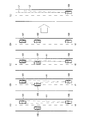
- FIG. 2A to 2D are schematic diagrams illustrating an example of a travel scene according to the embodiment of the present invention in time series
- FIG. 2E is a schematic diagram illustrating an estimation result of a travel locus of another vehicle in front of the host vehicle.
- the travel locus estimation device can be mounted on, for example, a vehicle 100 (hereinafter, a vehicle denoted by reference numeral 100 is referred to as “own vehicle”).
- a travel locus estimation apparatus includes an electronic control unit (ECU) 1, a surrounding vehicle sensor 2, a wheel speed sensor 3, a yaw rate sensor 4, and a driving support system 5.
- ECU electronice control unit
- the surrounding vehicle sensor 2 is mounted on the host vehicle 100.
- the surrounding vehicle sensor 2 detects an object such as another vehicle traveling around the host vehicle 100 and outputs the detection result to the ECU 1.
- a millimeter wave radar, a laser radar, a laser range finder (LRF), a camera, or the like can be used, and the type and number of the surrounding vehicle sensors 2 are not particularly limited.
- the surrounding vehicle sensor 2 only needs to be able to detect an object such as another vehicle at least in the horizontal direction.
- the wheel speed sensor 3 is mounted on the host vehicle 100.
- the wheel speed sensor 3 detects the wheel speed of the host vehicle 100 and outputs the detection result to the ECU 1.
- the yaw rate sensor 4 is mounted on the host vehicle 100.
- the yaw rate sensor 4 detects the change rate (yaw rate) of the yaw angle of the host vehicle 100 and outputs the detection result to the ECU 1.
- the ECU 1 is a controller that estimates a travel locus of another vehicle that travels around the host vehicle 100 based on the detection result of the surrounding vehicle sensor 2.
- the ECU 1 includes a processor 6 and a storage device 7.
- the processor 6 can be composed of, for example, a computer including a central processing unit (CPU), a main storage device, an input / output device, an input / output interface, a data bus, a semiconductor integrated circuit equivalent to the computer, and the like.
- a semiconductor integrated circuit including a programmable logic device (PLD) such as a field programmable gate array (FPGA) may be used.
- PLD programmable logic device
- FPGA field programmable gate array
- a functional logic circuit or a logic block set in a general-purpose semiconductor integrated circuit may be used.
- the storage device 7 can be configured by a semiconductor storage device, a magnetic storage device, an optical storage device, or the like, and may include a register, a cache memory, or the like.
- FIGS. 2A to 2E an example of a traveling scene to which the traveling locus estimation apparatus according to the embodiment of the present invention is applied will be described with reference to time-series displays in FIGS. 2A to 2E.
- the host vehicle 100 is traveling in the right lane of the two lanes on one side, and another vehicle 101 that is a preceding vehicle is traveling in front of the host vehicle 100 in the same lane.
- Another vehicle 102 is traveling in the left lane.
- 2A indicates a range in which the other vehicle 101 can be detected by the surrounding vehicle sensor 2 of the host vehicle 100. There is no other object between the host vehicle 100 and the other vehicle 101 in front of the host vehicle 100, and the other vehicle 101 can be detected by the surrounding vehicle sensor 2 without being occluded.
- the other vehicle 102 traveling in the left lane starts changing the lane to the right lane.
- the other vehicle 102 whose lane has been changed enters between the own vehicle 100 and the other vehicle 101, a part of the other vehicle 101 is occluded by the other vehicle 102, and the surrounding vehicle sensor 2, the range A1 in which the other vehicle 101 can be detected becomes narrower.
- the lane change of the other vehicle 102 is completed, the entire rear portion of the other vehicle 101 is occluded by the other vehicle 102, and the other vehicle 101 cannot be detected by the surrounding vehicle sensor 2.
- the travel locus estimation apparatus can accurately estimate the travel locus of the other vehicle 101 even when a part of the other vehicle 101 is occluded as shown in FIG. 2C. Is.
- the processor 6 includes an occlusion determination circuit 11, a reference point setting circuit 12, a movement amount calculation circuit 15, and a travel locus estimation circuit 16 as logical hardware resources.
- the shielding determination circuit 11, the reference point setting circuit 12, the movement amount calculation circuit 15, and the travel locus estimation circuit 16 are configured by PLD or the like, a configuration in which an actual logic circuit block corresponds may be used.
- the shielding determination circuit 11 determines for each other vehicle whether or not a part of the other vehicle traveling around the host vehicle 100 is occluded based on the detection result of the other vehicle by the surrounding vehicle sensor 2 (in other words, For example, it is determined whether or not there is another vehicle that is occluded around the host vehicle 100). Based on the detection result of the other vehicle by the surrounding vehicle sensor 2, the shielding determination circuit 11 determines whether another vehicle such as an approaching vehicle enters between the host vehicle 100 and another vehicle such as a preceding vehicle. It is determined that a part is occluded. On the other hand, when no other object enters between the host vehicle 100 and the other vehicle, the shielding determination circuit 11 determines that the other vehicle is occluded.
- the shielding determination circuit 11 When determining that a part of the other vehicle is occluded, the shielding determination circuit 11 identifies the direction in which the other vehicle is occluded (the occlusion direction) when viewed from the host vehicle 100. For example, when viewed from the host vehicle 100, it is specified whether another vehicle is occluded from the left side or occluded from the right side.
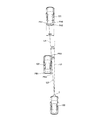
- FIG. 4 is a traveling scene similar to FIG. 2A, in which another vehicle 101 that is a preceding vehicle is traveling in front of the host vehicle 100, and another vehicle 102 is traveling in front of the host vehicle 100. Indicates.
- the shielding determination circuit 11 determines whether or not the other vehicle 101 is occluded from the left side by the other vehicle 102 is illustrated.
- the surrounding vehicle sensor 2 detects the position of the other vehicle 101 including the distance and direction of the other vehicle 101 traveling in front of the host vehicle 100. Information on the position of the other vehicle 101 detected by the surrounding vehicle sensor 2 is output to the ECU 1 and stored in the storage device 7. The surrounding vehicle sensor 2 further detects the position of the other vehicle 102 including the distance, direction, and the like of the other vehicle 102 traveling in the left front of the host vehicle 100. Information on the position of the other vehicle 102 detected by the surrounding vehicle sensor 2 is output to the ECU 1 and stored in the storage device 7.
- the shielding determination circuit 11 extracts the left end PA1 of the position of the other vehicle 101 from the position information of the other vehicle 101 detected by the surrounding vehicle sensor 2, for example, to determine occlusion from the left side.
- the left end PA ⁇ b> 1 is a position that becomes a left boundary of the other vehicle 101 when viewed from the host vehicle 100.
- the left end PA1 is an example of the left rear corner of the other vehicle 101, but depending on the relative position between the host vehicle 100 and the other vehicle 101, the left front corner of the other vehicle 101 may be It may be the left end.
- the shielding determination circuit 11 and the reference line L0 parallel to the front-rear direction of the host vehicle 100 and the position of the host vehicle 100 (for example, the surrounding vehicle sensor 2).
- the horizontal angle ⁇ A formed by the straight line LA connecting the position) and the left end PA1 of the position of the other vehicle 101 is calculated.
- the shielding determination circuit 11 further extracts the right end PB3 of the position of the other vehicle 102 from the position information of the other vehicle 102 detected by the surrounding vehicle sensor 2.
- the right end portion PB3 is a position that becomes the right boundary of the other vehicle 102 when viewed from the host vehicle 100. Note that the right end PB3 is an example of the right front corner of the other vehicle 102, but depending on the relative position between the host vehicle 100 and the other vehicle 102, the right rear corner PB2 of the other vehicle 102 is shown. May be the right end.
- the shielding determination circuit 11 uses the extracted right end portion PB3 of the position of the other vehicle 102 and the reference line L0 parallel to the front-rear direction of the host vehicle 100 and the position of the host vehicle 100 (for example, the surrounding vehicle sensor 2).
- the horizontal angle ⁇ B formed by the straight line LB connecting the position) and the right end PB3 of the position of the other vehicle 102 is calculated.
- the shielding determination circuit 11 determines whether or not the other vehicle 101 is occluded from the left side using the calculated angles ⁇ A and ⁇ B. For example, it is determined whether or not the other vehicle 101 is occluded from the left side by determining whether or not the angles ⁇ A and ⁇ B satisfy the relationship of the expression (1). ⁇ B ⁇ A ⁇ ⁇ + ⁇ (1)
- ⁇ is the horizontal angular resolution of the surrounding vehicle sensor 2
- ⁇ is a safety factor depending on the sensing performance of the surrounding vehicle sensor 2, and may be set to a value close to ⁇ .
- the shielding determination circuit 11 determines that the other vehicle 101 is occluded from the left side when the relationship of Expression (1) is satisfied, and the other vehicle 101 is occluded from the left side when the relationship of Expression (1) is not satisfied. Judge that it is not.
- Expression (1) instead of using Expression (1), instead of using Expression (1), instead of using Expression (1), instead of using Expression (1), for example, by determining whether or not the angle ⁇ B is less than the value obtained by adding ⁇ + ⁇ to the angle ⁇ A, You may determine whether it is occluded.
- the shielding determination circuit 11 may determine that the other vehicle 101 is occluded from the left side.
- the shielding determination circuit 11 may determine that the other vehicle 101 is not occluded from the left side.
- the shielding determination circuit 11 may calculate the distance between the host vehicle 100 and the other vehicles 101 and 102, respectively. The shielding determination circuit 11 determines that the distance between the host vehicle 100 and the other vehicle 101 is greater than the distance between the host vehicle 100 and the other vehicle 102 and the angles ⁇ A and ⁇ B satisfy the relationship of the expression (1). The other vehicle 101 may be determined to be occluded.
- the shielding determination circuit 11 does not perform the occlusion determination on the other vehicle 102. It may be.
- FIG. 5 is a driving scene similar to FIG. 2C, and another vehicle 102 that has traveled in front of the left side of the host vehicle 100 enters between the host vehicle 100 and the other vehicle 101 due to a lane change or the like.
- a part of the other vehicle 101 is occluded from the left side.
- the left end PA1 of the position of the other vehicle 101 is detected by occlusion on a straight line LB connecting the position of the surrounding vehicle sensor 2 and the right end PB3 of the position of the other vehicle 102. .
- An angle ⁇ A formed by a reference line L0 parallel to the front-rear direction of the host vehicle 100 and a straight line LA connecting the position of the surrounding vehicle sensor 2 and the left end PA1 of the position of the other vehicle 101 is the front-rear direction of the host vehicle 100 Is equal to an angle ⁇ B formed by a reference line L0 parallel to the straight line LB connecting the position of the surrounding vehicle sensor 2 and the right end PB3 of the position of the other vehicle 102.
- the shielding determination circuit 11 determines that a part of the other vehicle 101 is occluded by the other vehicle 102 from the left side because the angles ⁇ A and ⁇ B satisfy the relationship of the expression (1).
- the left end PA1 of the position of the other vehicle 101 may be estimated from the right end PA2 of the position of the other vehicle 101 and the vehicle width WA of the other vehicle 101.
- the shielding determination circuit 11 calculates the angles ⁇ A and ⁇ B, and instead of determining occlusion using the equation (1), based on the position information of the other vehicle 101 detected by the surrounding vehicle sensor 2,
- the end PA2 on the right side of the position of the other vehicle 101 can be extracted and the vehicle width WA of the other vehicle 101 is less than a predetermined threshold, it is determined that a part of the other vehicle 101 is occluded from the left side. May be.
- the vehicle width WA of the other vehicle 101 can be estimated by extracting the left end PA1 and the right end PA2 of the position of the other vehicle 101 by the surrounding vehicle sensor 2 before part of the other vehicle 101 is occluded.
- the shielding determination circuit 11 may determine whether or not the other vehicle 102 is occluded, similarly to determining whether or not the other vehicle 101 is occluded. For example, in the traveling scene shown in FIG. 4, since there is no other object such as another vehicle between the host vehicle 100 and the other vehicle 102, the shielding determination circuit 11 determines that the other vehicle 102 is not occluded. To do.
- the reference point setting circuit 12 includes a vehicle width estimation unit 13 and a reference point setting unit 14.
- the vehicle width estimation unit 13 extracts end portions PA1 and PA2 of the position of the other vehicle 101 from the information on the position of the other vehicle 101 detected by the surrounding vehicle sensor 2, and uses the extracted end portions PA1 and PA2.
- the vehicle width WA of the vehicle 101 is estimated. For example, in the traveling scene shown in FIG. 4, when the shielding determination circuit 11 determines that the other vehicle 101 is not occluded, the vehicle width estimation unit 13 determines the distance between the end portions PA1 and PA2 of the position of the other vehicle 101. And the calculated distance is estimated as the vehicle width WA of the other vehicle 101.
- the estimated vehicle width WA is stored in the storage device 7.
- a low-pass filter or the like can be used to estimate the vehicle width WA more accurately and stably. Can do.
- the reference point setting unit 14 includes information on the end portions PA1 and PA2 of the position of the other vehicle 101, a determination result by the shielding determination circuit 11, and information on the vehicle width WA of the other vehicle 101 estimated by the vehicle width estimation unit 13. From this, a reference point for calculating the travel locus of the other vehicle 101 is estimated (set). For example, in the traveling scene shown in FIG. 4, when it is determined by the shielding determination circuit 11 that the other vehicle 101 is not occluded, the center point PA0 of the end portions PA1 and PA2 of the position of the other vehicle 101 is the reference point. Set as.
- the front-rear direction of the host vehicle 100 is the x direction
- the vehicle width direction orthogonal to the front-rear direction of the host vehicle 100 is the y direction
- the position coordinates of the left end PA1 of the position of the other vehicle 101 are (x 1 , y 1 )
- the position coordinates (x 0 , y 0 ) of the center point P0 are calculated by the expression (2), where the position coordinates of the right end PA2 are (x 2 , y 2 ).
- x 0 (x 1 + x 2 ) / 2
- y 0 (y 1 + y 2 ) / 2 (2)
- the shielding determination circuit 11 determines that a part of the other vehicle 101 is occluded from the left side, the left end PA1 of the position of the other vehicle 101 is occluded and the surrounding vehicle Recognition by the sensor 2 becomes impossible.
- the right end PA2 of the position of the other vehicle 101 in the direction opposite to the occlusion direction can be continuously recognized by the surrounding vehicle sensor 2.
- the reference point setting unit 14 estimates the occluded part of the other vehicle 101 based on the right end PA2 opposite to the left side where the part of the other vehicle 101 is occluded. Set the reference point. For example, the reference point setting unit 14 uses the right end PA2 of the position of the other vehicle 101 and the information on the vehicle width WA of the other vehicle 101 read from the storage device 7 to the left end where the other vehicle 101 is occluded.
- the part PA1 is estimated.
- the right direction of the vehicle width direction of the host vehicle 100 is defined as the positive direction of the position coordinates, and the position coordinates (x 2 , y 2 ) of the right end PA2 are leftward (negative direction) by the vehicle width WA.
- the shifted position coordinates (x 2 ⁇ WA, y 2 ) may be estimated as the left end PA1.
- the center point P0 has the right direction in the vehicle width direction of the host vehicle 100 as the positive direction of the position coordinates, and the position coordinates (x 2 , y 2 ) of the right end PA2 are left by half of the vehicle width WA. It can be estimated by shifting in the (negative direction).
- the vehicle width WA of the other vehicle 101 used when the reference point setting unit 14 estimates the occluded portion of the other vehicle 101 is determined by the surrounding vehicle sensor 2 before the other vehicle 101 is partially occluded.
- the position 101 can be detected, and the vehicle width estimation unit 13 can extract and estimate the left end PA1 and the right end PA2 of the position of the other vehicle 101.
- the vehicle width estimation unit 13 may estimate the distance between the left end PA1 and the right end PA2 as the vehicle width WA of the other vehicle 101.
- the estimated vehicle width WA is stored in the storage device 7 in advance.
- the movement amount calculation circuit 15 uses the motion information of the host vehicle 100 such as the wheel speed of the host vehicle 100 detected by the wheel speed sensor 3 and the yaw rate of the host vehicle 100 detected by the yaw rate sensor 4.
- the amount of movement ( ⁇ X, ⁇ Y, ⁇ ) is calculated.
- ⁇ X is a translational movement amount of the host vehicle 100 in the front-rear direction
- ⁇ Y is a translational movement amount of the host vehicle 100 in the vehicle width direction
- ⁇ is a rotation amount.
- the travel locus estimation circuit 16 is based on the reference point PA0 of the other vehicle 101 calculated by the reference point setting circuit 12 and the movement amounts ( ⁇ X, ⁇ Y, ⁇ ) calculated by the movement amount calculation circuit 15. Is calculated (estimated). For example, the time series PA0 (i ) of the reference point PA0 of the other vehicle 101 up to the previous processing cycle (for example, the i-th processing cycle is the i-th processing cycle). -5) , PA0 (i-4) , PA0 (i-3) , PA0 (i-2) , PA0 (i-1) are stored in the storage device 7.
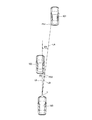
- the travel locus estimation circuit 16 Based on the amount of movement of the host vehicle 100, the travel locus estimation circuit 16 performs time series PA0 (i-5) , PA0 (i-4) , PA0 (i ) of the reference point PA0 of the other vehicle 101 as shown in FIG. -3) , PA0 (i-2) , PA0 (i-1) are updated.
- the reference point PA0 i of the other vehicle 101 calculated by the reference point setting circuit 12 in this processing cycle is used as the time series PA0 (i-5) , PA0 (i-4) ,
- PA0 (i-3) , PA0 (i-2) , PA0 (i-1) , time series PA0 (i-5) , PA0 (i-4) , PA0 (i-4) A travel locus L3 of the other vehicle 101 including PA0 (i-3) , PA0 (i-2) , PA0 (i-1) , and PA0 i is estimated.
- the travel locus L3 may be appropriately corrected by linear approximation, curve approximation, or the like.
- the estimated travel locus L3 of the other vehicle 101 is output to the driving support system 5.
- the driving support system 5 includes a processor and a storage device in the same configuration as the ECU 1.
- the driving support system 5 may be built in the ECU 1.
- the driving assistance system 5 issues a driving assistance control command to the traveling control device of the host vehicle 100 based on the traveling locus L3 of the other vehicle 101 calculated by the traveling locus estimation circuit 16.
- the driving support system 5 performs acceleration / deceleration control, braking control, steering control, or the like of the own vehicle 100 to follow the other vehicle 101 based on the traveling locus L3 of the other vehicle 101 calculated by the traveling locus estimation circuit 16.
- the control command may be issued.
- the driving support system 5 calculates the amount of deviation in the vehicle width direction between the travel locus L3 of the other vehicle 101 and the travel locus of the host vehicle 100 while following the other vehicle 101, and the amount of deviation is predetermined.
- the tracking target may be switched to the other vehicle 102 when the threshold value is reached.
- step S ⁇ b> 1 the surrounding vehicle sensor 2 detects the position of the other vehicle 101 that travels around the host vehicle 100.
- the surrounding vehicle sensor 2 detects the position of the other vehicle 102 that travels around the host vehicle 100.
- step S ⁇ b> 2 the shielding determination circuit 11 determines whether the other vehicle 101 is occluded by the other vehicle 102 from the left side or the right side based on the positions of the other vehicles 101 and 102 detected by the surrounding vehicle sensor 2. .
- the shielding determination circuit 11 determines whether the other vehicle 101 is occluded by the other vehicle 102 from the left based on the left end PA1 of the other vehicle 101 and the right end PB3 of the other vehicle 102. Determine whether or not.
- the process proceeds to step S3.
- step S ⁇ b> 3 the vehicle width estimation unit 13 extracts and extracts the left end PA ⁇ b> 1 and the right end PA ⁇ b> 2 of the position of the other vehicle 101 based on the position of the other vehicle 101 detected by the surrounding vehicle sensor 2.
- the vehicle width WA of the other vehicle 101 is estimated using the ends PA1 and PA2. Information on the estimated vehicle width WA is stored in the storage device 7.
- step S2 when it is determined in step S2 that the other vehicle 101 is occluded by the other vehicle 102 from the left or right side, the process proceeds to step S4.
- step S ⁇ b> 4 the reference point setting unit 14 has an end on the opposite side to the side on which the other vehicle 101 is occluded (the right side here) of the left end PA ⁇ b> 1 and the right end PA ⁇ b> 2 of the position of the other vehicle 101.
- the left side PA1 that is the occluded part of the other vehicle 101 and the left side PA1 from the information of the vehicle width WA read from the storage device 7 And a center point PA0 with the right end A2.
- step S5 when passing through step S3, the reference point setting unit 14 determines the position of the left side of the position of the other vehicle 101 based on the position information of the other vehicle 101 detected by the surrounding vehicle sensor 2 in step S1.
- a center point PA0 between the end PA1 and the right end PA2 is calculated as a reference point.
- the reference point setting unit 14 uses the center point PA0 between the left end PA1 and the right end PA2 of the position of the other vehicle 101 estimated in step S4 as a reference point. calculate.
- step S ⁇ b> 6 the movement amount calculation circuit 15, for example, determines the movement amount (the movement amount (i.e. ⁇ X, ⁇ Y, ⁇ ) is calculated.
- step S7 the travel locus estimation circuit 16 calculates the time series PA0 (i-5) , PA0 (i-4) , PA0 (i-3) of the reference point PA0 of the other vehicle 101 calculated by the reference point setting circuit 12. , PA0 (i-2) , PA0 (i-1) , PA0 i and the travel amount ( ⁇ X, ⁇ Y, ⁇ ) of the host vehicle 100 calculated by the travel amount calculation circuit 15, the travel locus of the other vehicle 101.
- Estimate L3 the time series PA0 (i-5) , PA0 (i-4) , PA0 (i-3) of the reference point PA0 of the other vehicle 101 calculated by the reference point setting circuit 12.
- step S8 the ECU 1 determines whether or not the ignition switch of the host vehicle 100 is off. If it is determined that the ignition switch is off, the process is terminated. On the other hand, if it is determined that the ignition switch is not OFF, the procedure returns to step S1.
- the traveling locus estimation program according to the embodiment of the present invention causes a computer such as the ECU 1 constituting the traveling locus estimation apparatus illustrated in FIG. 1 to execute a series of processes of the traveling locus estimation method illustrated in FIG. Can do.
- the travel locus estimation program according to the embodiment of the present invention can be stored in, for example, the storage device 7 or the like.
- the reference point PA0 of the other vehicle 101 is set based on the information of the end portion in the direction opposite to the direction in which the other vehicle 101 is occluded.
- other vehicles based on the time series PA0 (i-5) , PA0 (i-4) , PA0 (i-3) , PA0 (i-2) , PA0 (i-1) , PA0 i of the reference point PA0
- a traveling locus L3 of 101 is estimated. Thereby, even when a part of the other vehicle 101 is occluded, the traveling locus L3 of the other vehicle 101 can be accurately estimated.
- the occluding determination circuit 11 indicates that a part of the other vehicle 101 is occluded. judge.
- the reference point setting unit 14 detects the left end PA1 and the right side of the position of the other vehicle 101. Since the process of estimating the center point PA0 of the end PA2 is performed, the calculation load can be reduced.
- the shielding determination circuit 11 has an angle ⁇ A formed by a reference line L0 parallel to the front-rear direction of the host vehicle 100 and a straight line LA connecting the left end PA1 of the position of the other vehicle 101 and the position of the host vehicle 100. Based on an angle ⁇ B formed by a reference line L0 parallel to the front-rear direction of the host vehicle 100 and a straight line LB connecting the right end PB3 of the position of the other vehicle 102 and the position of the host vehicle 100, Determine whether some are occluded. Thereby, the timing at which the occlusion of the other vehicle 101 starts and the direction in which the other vehicle 101 is occluded can be accurately identified.
- the reference point setting unit 14 determines that the center point of the left end PA1 and the right end PA2 of the other vehicle 101 position. PA0 is estimated, and the estimated center point PA0 is set as a reference point. Thereby, even when a part of the other vehicle 101 traveling around the host vehicle 100 is occluded, the reference point PA0 of the other vehicle 101 can be continuously estimated with high accuracy.
- the reference point setting unit 14 determines the left end PA1 and the right side of the position of the other vehicle 101.
- One of the end portions PA2 is set as a reference point.
- the reference point setting unit 14 may set the center point PA0 of the left end PA1 and the right end PA2 as a reference point.
- the traveling locus estimation circuit 16 updates the time series of the reference points based on the movement amount of the host vehicle 100 and accumulates it in the storage device 7.
- the travel locus estimation circuit 16 further updates the time series of the left end PA1 and the right end PA2 even when the left end PA1 and the right end PA2 are not set as reference points.
- the data is accumulated in the storage device 7.
- the reference point setting unit 14 is on the left side of the position of the other vehicle 101.
- an end portion opposite to the direction in which the other vehicle 101 is occluded is set as a reference point.
- the travel locus estimation circuit 16 reads the time series of the reference point PA2 from the storage device 7, and as shown in FIG.
- the left end PA1 and the right side of the position of the other vehicle 101 are detected.
- the end PA2 the end opposite to the occlusion direction is set as a reference point
- the time series corresponding to the reference point is read from the storage device 7, and the travel locus L4 of the other vehicle 101 is calculated.
- the travel locus of the other vehicle 101 can be estimated based on the time series of the reference points that can be continuously detected by the surrounding vehicle sensor 2 without estimating the portion where the other vehicle 101 is occluded.
- the shielding determination circuit 11 determines whether or not the other vehicle 101 in front of the host vehicle 100 is occluded from the left side.
- the shielding determination circuit 11 is on the right side of the position of the other vehicle 101. It is only necessary to determine whether or not the other vehicle 101 is in the occlusion state from the right side using the end portion PA2 and the left end portion PB4 of the position of the other vehicle 102.
- the right end PA ⁇ b> 2 of the position of the other vehicle 101 is a position serving as a right boundary of the other vehicle 101 when viewed from the host vehicle 100, and here is a corner of the right rear portion of the other vehicle 101.
- the left end portion PB4 of the position of the other vehicle 102 is a position that becomes the left boundary of the other vehicle 102 when viewed from the host vehicle 100, and here is a corner portion of the left front portion of the other vehicle 102.
- the shielding determination circuit 11 calculates an angle ⁇ A formed by a reference line L0 parallel to the front-rear direction of the host vehicle 100 and a straight line LA connecting the right end PA2 of the position of the other vehicle 101 and the host vehicle 100. .
- the shielding determination circuit 11 further calculates an angle ⁇ B formed by a reference line L0 parallel to the front-rear direction of the host vehicle 100 and a straight line LB connecting the left end portion PB4 of the position of the other vehicle 102 and the host vehicle 100.
- the shielding determination circuit 11 determines that a part of the other vehicle 101 is occluded from the right side by the other vehicle 102.
- the shielding determination circuit 11 determines that a part of the other vehicle 101 is not occluded by the other vehicle 102 from the right side.
- the left end portion PA ⁇ b> 1 of the position of the other vehicle 101 in front of the host vehicle 100 is in the vehicle width direction of the host vehicle 100.
- the case where it is on the left side of the center position in the vehicle width direction is illustrated.
- the left end PA ⁇ b> 1 of the position of the other vehicle 101 in front of the host vehicle 100 is the center position in the vehicle width direction of the host vehicle 100 in the vehicle width direction of the host vehicle 100. It is also possible to be on the right side.
- the shielding determination circuit 11 when determining whether the other vehicle 101 in front of the host vehicle 100 is occluded from the left side, the shielding determination circuit 11 is parallel to the front-rear direction of the host vehicle 100.
- a reference line L0 and a straight line LA connecting the left end (left rear corner of the other vehicle 101) PA1 and the own vehicle 100 when viewed from the own vehicle 100 are formed.
- the angle ⁇ A is calculated.
- the shielding determination circuit 11 further connects the reference line L0 parallel to the front-rear direction of the host vehicle 100 and the right end PB2 positioned on the rightmost side of the other vehicle 102 when viewed from the host vehicle 100 and the host vehicle 100.
- An angle ⁇ B formed by the straight line LB is calculated.
- the shielding determination circuit 11 when the calculated angles ⁇ A and ⁇ B do not satisfy the formula (1), the shielding determination circuit 11 causes the other vehicle 101 to be occluded from the left side by the other vehicle 102. Is determined. On the other hand, when the calculated angles ⁇ A and ⁇ B satisfy Expression (1), the shielding determination circuit 11 determines that the other vehicle 101 is not occluded from the left side by the other vehicle 102.
- the present invention can be used for a traveling locus estimation method and a traveling locus estimation device that can accurately estimate the traveling locus of another vehicle even when a part of the other vehicle traveling around the host vehicle is occluded. .
Landscapes
- Engineering & Computer Science (AREA)
- Automation & Control Theory (AREA)
- Transportation (AREA)
- Mechanical Engineering (AREA)
- Physics & Mathematics (AREA)
- Mathematical Physics (AREA)
- Traffic Control Systems (AREA)
Abstract
自車両の周囲を走行する他車両の一部がオクルージョンされた場合でも、他車両の走行軌跡を精度良く推定することができる走行軌跡推定方法を提供する。自車両の周囲を走行する他車両の位置を検出し(S1)、他車両の位置に基づいて他車両の走行軌跡を推定し(S2~S7)、他車両の一部がオクルージョンされた場合には、他車両の位置の左側及び右側の端部のうちの他車両がオクルージョンされた方向とは逆方向の端部に基づいて、他車両の参照点を設定し(S2,S4,S5)、設定された参照点の時系列に基づいて、他車両の走行軌跡を推定する(S6,S7)。
Description
本発明は、走行軌跡推定方法及び走行軌跡推定装置に関する。
自車両と先行車との間に進入車が割り込むような場合に、進入車の走行軌跡と先行車の走行軌跡とのズレ量が閾値以下となる地点を特定し、特定した地点以降において進入車の走行軌跡に基づいて自車両の目標走行軌跡を設定する技術がある(特許文献1参照)。
しかしながら、特許文献1に記載の技術では、ズレ量の閾値を大きくすると、追従対象の切り替え時のズレ量が大きく、進入車の走行軌跡を自車両が追従しようとすると自車両がふらつく可能性がある。これを回避するため、ズレ量の閾値値を小さくすると、追従対象の切り替え前の先行車と進入車のオーバーラップが大きくなり、自車両から見たときに進入車により先行車の一部が遮蔽(オクルージョン)される。したがって、先行車の認識精度が低下し、先行車の認識結果に応じて推定する先行車の走行軌跡がふらつき、先行車の走行軌跡を精度良く推定できなくなる可能性がある。
上記問題点を鑑み、本発明は、自車両の周囲を走行する他車両の一部が遮蔽(オクルージョン)された場合でも、他車両の走行軌跡を精度良く推定することができる走行軌跡推定方法及び走行軌跡推定装置を提供することを目的とする。
本発明の態様は、自車両の周囲を走行する他車両の位置を検出し、他車両の位置に基づいて他車両の走行軌跡を推定する。このとき、他車両の一部がオクルージョンされた場合には、他車両の位置の左側及び右側の端部のうちの他車両がオクルージョンされた方向とは逆方向の端部に基づいて他車両の参照点を設定し、設定された参照点の時系列に基づいて他車両の走行軌跡を推定することを特徴とする走行軌跡推定方法及び走行軌跡推定装置であることを要旨とする。
本発明によれば、自車両の周囲を走行する他車両の一部がオクルージョンされた場合でも、他車両の走行軌跡を精度良く推定することができる走行軌跡推定方法及び走行軌跡推定装置を提供することができる。
次に、図面を参照して、本発明の実施形態を説明する。以下の図面の記載において、同一又は類似の部分には同一又は類似の符号を貼付している。但し、図面は模式的なものであり、厚みと平面寸法との関係、厚みの比率等は現実のものとは異なることに留意すべきである。また、図面相互間においても互いの寸法の関係や比率が異なる部分が含まれていることは勿論である。また、以下に示す実施形態は、本発明の技術的思想を具体化するための装置や方法を例示するものであって、本発明の技術的思想は、構成部品の材質、形状、構造、配置等を下記のものに特定するものではない。本発明の技術的思想は、特許請求の範囲に記載された請求項が規定する技術的範囲内において、種々の変更を加えることができる。
本発明の実施形態に係る走行軌跡推定装置は、図1に示すように、例えば車両100に搭載可能である(以下、符号100を付した車両を「自車両」という)。本発明の実施形態に係る走行軌跡推定装置は、電子制御ユニット(ECU)1、周囲車両センサ2、車輪速センサ3、ヨーレートセンサ4及び運転支援システム5を備える。
周囲車両センサ2は、自車両100に搭載されている。周囲車両センサ2は、自車両100の周囲を走行する他車両等の物体を検出し、検出結果をECU1に出力する。周囲車両センサ2としては、例えばミリ波レーダやレーザーレーダ、レーザレンジファインダ(LRF)、カメラ等が使用可能であり、周囲車両センサ2の種類や数は特に限定されない。周囲車両センサ2は、少なくとも水平方向において、他車両等の物体を検出可能であればよい。
車輪速センサ3は、自車両100に搭載されている。車輪速センサ3は、自車両100の車輪速を検出し、検出結果をECU1に出力する。ヨーレートセンサ4は、自車両100に搭載されている。ヨーレートセンサ4は、自車両100のヨー角の変化速度(ヨーレート)を検出し、検出結果をECU1に出力する。
ECU1は、周囲車両センサ2の検出結果に基づいて、自車両100の周囲を走行する他車両の走行軌跡を推定するコントローラである。ECU1は、プロセッサ6及び記憶装置7を有する。プロセッサ6は、例えば中央演算処理装置(CPU)、主記憶装置、入出力装置、入出力インターフェイス、データバス等を含むコンピュータやコンピュータに等価な半導体集積回路等で構成することができる。プロセッサ6を半導体集積回路で構成する場合は、フィールド・プログラマブル・ゲート・アレイ(FPGA)等のプログラマブル・ロジック・デバイス(PLD)を含む半導体集積回路を利用してもよい。或いは、汎用の半導体集積回路中に設定される機能的な論理回路や論理ブロック等でも構わない。記憶装置7は、半導体記憶装置、磁気記憶装置又は光学記憶装置等で構成でき、レジスタ、キャッシュメモリ等を含んだ構成でもよい。
次に、図2A~図2Eの時系列表示を参照して、本発明の実施形態に係る走行軌跡推定装置が適用される走行シーンの一例を説明する。図2Aの時刻t0において、片側2車線のうちの右側の車線を自車両100が走行しており、同一車線の自車両100の前方には先行車両である他車両101が走行している。左側の車線には他車両102が走行している。図2Aの破線の領域A1は、自車両100の周囲車両センサ2により他車両101を検出可能な範囲を示す。自車両100と、自車両100の前方の他車両101との間には他の物体が存在せず、他車両101はオクルージョンされずに周囲車両センサ2により検出可能である。
次に、図2Bの時刻t1において、左側の車線を走行していた他車両102が右側の車線に車線変更を開始する。次に、図2Cの時刻t2において、車線変更した他車両102が自車両100と他車両101の間に進入してくると、他車両101の一部が他車両102によりオクルージョンされ、周囲車両センサ2により他車両101を検出可能な範囲A1が狭くなってくる。その後、図2Dの時刻t3において、他車両102の車線変更が完了し、他車両101の後部全部が他車両102によりオクルージョンされ、周囲車両センサ2により他車両101が検出できなくなっている。
図2Cに示すように他車両101の一部がオクルージョンされると、オクルージョンされた他車両101の検出精度が低下する場合がある。この結果、周囲車両センサ2の検出結果に基づいて他車両101の走行軌跡を推定する場合には、図2Eに示すように、他車両101の実際の走行軌跡L1に対して、他車両101の推定される走行軌跡L2が乖離し、他車両101の走行軌跡L2の推定精度が低下する場合がある。これに対して、本発明の実施形態に係る走行軌跡推定装置は、図2Cに示すように他車両101の一部がオクルージョンされる場合でも、他車両101の走行軌跡を精度良く推定可能とするものである。
プロセッサ6は、図3に示すように、遮蔽(オクルージョン)判定回路11、参照点設定回路12、移動量算出回路15及び走行軌跡推定回路16を論理的なハードウェア資源として備える。なお、PLD等で、遮蔽判定回路11、参照点設定回路12、移動量算出回路15及び走行軌跡推定回路16を構成した場合は、実際の論理回路ブロックが対応するような構成でも構わない。
遮蔽判定回路11は、周囲車両センサ2による他車両の検出結果に基づいて、自車両100の周囲を走行する他車両の一部がオクルージョンされているか否かを他車両毎に判定する(換言すれば、自車両100の周囲に、オクルージョンされている他車両が存在するか否かを判定する)。遮蔽判定回路11は、周囲車両センサ2による他車両の検出結果に基づいて、自車両100と先行車両等の他車両との間に、進入車等の他の物体が進入した場合、他車両の一部がオクルージョンされていると判定する。一方、自車両100と他車両との間に他の物体が進入していない場合、遮蔽判定回路11は、他車両がオクルージョンされていると判定する。
遮蔽判定回路11は、他車両の一部がオクルージョンされていると判定する場合には、自車両100から見たときに、他車両がオクルージョンされている方向(オクルージョン方向)を特定する。例えば、自車両100から見たときに、他車両が左側からオクルージョンされているか、或いは右側からオクルージョンされているかを特定する。
次に、図4及び図5を参照して、遮蔽判定回路11による他車両101のオクルージョン状態の判定処理の一例を説明する。図4は、図2Aと同様の走行シーンであり、自車両100の前方に先行車両である他車両101が走行しており、自車両100の左前方には他車両102が走行している様子を示す。ここでは、遮蔽判定回路11が、他車両102により他車両101が左側からオクルージョンされているか否かを判定する場合を例示する。
周囲車両センサ2は、自車両100の前方を走行する他車両101の距離や方位等を含む他車両101の位置を検出する。周囲車両センサ2により検出された他車両101の位置の情報は、ECU1に出力され、記憶装置7に格納される。周囲車両センサ2は更に、自車両100の左前方を走行する他車両102の距離や方位等を含む他車両102の位置を検出する。周囲車両センサ2により検出された他車両102の位置の情報は、ECU1に出力され、記憶装置7に格納される。
遮蔽判定回路11は、例えば左側からのオクルージョンを判定するために、周囲車両センサ2により検出された他車両101の位置の情報から、他車両101の位置の左側の端部PA1を抽出する。左側の端部PA1は、自車両100から見たときに、他車両101の左側の境界となる位置である。なお、左側の端部PA1は、他車両101の左側後部の角部である場合を例示するが、自車両100と他車両101との相対位置によっては他車両101の左側前部の角部が左側の端部となる場合もある。遮蔽判定回路11は、抽出された他車両101の位置の左側の端部PA1に基づいて、自車両100の前後方向に平行な基準線L0と、自車両100の位置(例えば周囲車両センサ2の位置)と他車両101の位置の左側の端部PA1とを結ぶ直線LAとがなす水平方向の角度φAを算出する。
遮蔽判定回路11は更に、周囲車両センサ2により検出された他車両102の位置の情報から、他車両102の位置の右側の端部PB3を抽出する。右側の端部PB3は、自車両100から見たときに、他車両102の右側の境界となる位置である。なお、右側の端部PB3は、他車両102の右側前部の角部である場合を例示するが、自車両100と他車両102との相対位置によっては他車両102の右側後部の角部PB2が右側の端部となる場合もある。遮蔽判定回路11は、抽出された他車両102の位置の右側の端部PB3を用いて、自車両100の前後方向に平行な基準線L0と、自車両100の位置(例えば周囲車両センサ2の位置)と他車両102の位置の右側の端部PB3とを結ぶ直線LBとがなす水平方向の角度φBを算出する。
遮蔽判定回路11は、算出された角度φA,φBを用いて、他車両101が左側からオクルージョンされているか否かを判定する。例えば、角度φA,φBが式(1)の関係を満たすか否かを判定することにより、他車両101が左側からオクルージョンされているか否かを判定する。
φB-φA≦Δθ+α …(1)
φB-φA≦Δθ+α …(1)
ここで、Δθは周囲車両センサ2の水平方向の角度分解能であり、αは周囲車両センサ2のセンシング性能に依存する安全係数で、Δθに近い値に設定するとよい。遮蔽判定回路11は、式(1)の関係を満たす場合に、他車両101が左側からオクルージョンされていると判定し、式(1)の関係を満たさない場合に、他車両101が左側からオクルージョンされていないと判定する。なお、式(1)を用いたオクルージョンの判定方法を例示したが、式(1)を用いる代わりに、例えば、角度φBが角度φAにΔθ+αを加えた値未満か否かを判定することにより、オクルージョンされているか否かを判定してもよい。角度φBが角度φAにΔθ+αを加えた値未満の場合に、遮蔽判定回路11は、他車両101が左側からオクルージョンされていると判定してもよい。一方、角度φBが角度φAにΔθ+αを加えた値以上の場合に他車両101が左側からオクルージョンされていないと判定してもよい。
なお、他車両101が他車両102によりオクルージョンされているときには、自車両100と他車両101との間に他車両102が進入していることを意味するので、自車両100と他車両101との距離が、自車両100と他車両102との距離よりも大きいことが前提となる。このため、遮蔽判定回路11は、自車両100と他車両101,102の距離をそれぞれ算出してもよい。そして、遮蔽判定回路11は、自車両100と他車両101との距離が、自車両100と他車両102との距離よりも大きく、且つ角度φA,φBが式(1)の関係を満たす場合に、他車両101がオクルージョンされていると判定してもよい。一方、遮蔽判定回路11は、自車両100と他車両101との距離が、自車両100と他車両102との距離以下である場合には、他車両102に対してオクルージョンの判定を行わないようにしてもよい。
図5は、図2Cと同様の走行シーンであり、自車両100の左前方を走行していた他車両102が車線変更等により、自車両100と他車両101との間に進入し、自車両100から見たときに、他車両101の一部が左側からオクルージョンされている様子を示す。この場合、他車両101の位置の左側の端部PA1は、オクルージョンによって、周囲車両センサ2の位置と他車両102の位置の右側の端部PB3とを結ぶ直線LB上に検出されることになる。自車両100の前後方向に平行な基準線L0と、周囲車両センサ2の位置と他車両101の位置の左側の端部PA1とを結ぶ直線LAとがなす角度φAが、自車両100の前後方向に平行な基準線L0と、周囲車両センサ2の位置と他車両102の位置の右側の端部PB3とを結ぶ直線LBとがなす角度φBと同じになっている。遮蔽判定回路11は、角度φA,φBが、式(1)の関係を満たすため、他車両101の一部が左側から他車両102によりオクルージョンされていると判定する。なお、他車両101の位置の左側の端部PA1は、他車両101の位置の右側の端部PA2と他車両101の車幅WAから推定して用いてもよい。
また、遮蔽判定回路11は、角度φA,φBを算出して、式(1)を用いてオクルージョンを判定する代わりに、周囲車両センサ2により検出された他車両101の位置の情報に基づいて、他車両101の位置の右側の端部PA2を抽出でき、且つ他車両101の車幅WAが所定の閾値未満となった場合に、他車両101の一部が左側からオクルージョンされていると判定してもよい。他車両101の車幅WAは、他車両101の一部がオクルージョンされる前に周囲車両センサ2により他車両101の位置の左側の端部PA1及び右側の端部PA2を抽出して推定できる。
なお、遮蔽判定回路11は、他車両101がオクルージョンされているか否かを判定するのと同様に、他車両102がオクルージョンされているか否かを判定してもよい。例えば、図4に示す走行シーンでは、自車両100と他車両102との間には他車両等の他の物体が存在しないので、遮蔽判定回路11は、他車両102がオクルージョンされていないと判定する。
参照点設定回路12は、車幅推定部13及び参照点設定部14を有する。車幅推定部13は、周囲車両センサ2により検出された他車両101の位置の情報から、他車両101の位置の端部PA1,PA2を抽出し、抽出した端部PA1,PA2を用いて他車両101の車幅WAを推定する。例えば図4に示した走行シーンにおいて、遮蔽判定回路11により他車両101がオクルージョンされていないと判定された場合、車幅推定部13は、他車両101の位置の端部PA1,PA2間の距離を算出し、算出された距離を他車両101の車幅WAと推定する。推定された車幅WAは、記憶装置7に格納される。なお、他車両101の位置の端部PA1,PA2の検出精度は、周囲車両センサ2の分解能により変動するので、例えばローパスフィルタ等を用いるとより精度良く、安定して車幅WAを推定することができる。
参照点設定部14は、他車両101の位置の端部PA1,PA2の情報と、遮蔽判定回路11による判定結果と、車幅推定部13により推定された他車両101の車幅WAの情報とから、他車両101の走行軌跡を算出するための参照点を推定(設定)する。例えば、図4に示した走行シーンにおいて、遮蔽判定回路11により他車両101がオクルージョンされていないと判定された場合には、他車両101の位置の端部PA1,PA2の中心点PA0を参照点として設定する。この場合、自車両100の前後方向をx方向、自車両100の前後方向に直交する車幅方向をy方向とし、他車両101の位置の左側の端部PA1の位置座標を(x1,y1)、右側の端部PA2の位置座標を(x2,y2)として、中心点P0の位置座標(x0,y0)を式(2)により算出する。
x0=(x1+x2)/2
y0=(y1+y2)/2 …(2)
x0=(x1+x2)/2
y0=(y1+y2)/2 …(2)
図5に示した走行シーンにおいて、遮蔽判定回路11により他車両101の一部が左側からオクルージョンされていると判定された場合、他車両101の位置の左側の端部PA1はオクルージョンされて周囲車両センサ2により認識できなくなる。一方、オクルージョン方向と逆方向の他車両101の位置の右側の端部PA2は、周囲車両センサ2により継続して認識できる。
そこで、参照点設定部14は、他車両101の一部がオクルージョンされた左側と逆側である右側の端部PA2に基づいて、他車両101のオクルージョンされた部分を推定し、他車両101の参照点を設定する。例えば、参照点設定部14は、他車両101の位置の右側の端部PA2と、記憶装置7から読み出した他車両101の車幅WAの情報とから、他車両101のオクルージョンされた左側の端部PA1を推定する。例えば、自車両100の車幅方向の右方向を位置座標の正の方向として、右側の端部PA2の位置座標(x2,y2)を車幅WA分だけ左方向(負の方向)にずらした位置座標(x2-WA,y2)を左側の端部PA1と推定してもよい。参照点設定部14は更に、右側の端部PA2と左側の端部PA1の中心点P0=(x2-WA/2,y2)を推定し、推定された中心点P0を参照点として設定する。例えば、中心点P0は、自車両100の車幅方向の右方向を位置座標の正の方向として、右側の端部PA2の位置座標(x2,y2)を車幅WAの半分だけ左方向(負の方向)にずらすことにより推定できる。
なお、参照点設定部14が他車両101のオクルージョンされた部分を推定する際に用いる他車両101の車幅WAは、他車両101の一部がオクルージョンされる前に周囲車両センサ2により他車両101の位置を検出し、車幅推定部13により他車両101の位置の左側の端部PA1及び右側の端部PA2を抽出して推定できる。例えば、車幅推定部13により左側の端部PA1及び右側の端部PA2間の距離を他車両101の車幅WAと推定してもよい。推定された車幅WAは、記憶装置7に予め格納される。
移動量算出回路15は、例えば車輪速センサ3により検出された自車両100の車輪速と、ヨーレートセンサ4により検出された自車両100のヨーレート等の自車両100の運動情報から、自車両100の移動量(ΔX,ΔY,Δφ)を算出する。ΔXは自車両100の前後方向の並進移動量であり、ΔYは自車両100の車幅方向の並進移動量であり、Δφは回転量である。
走行軌跡推定回路16は、参照点設定回路12により算出された他車両101の参照点PA0と、移動量算出回路15により算出された移動量(ΔX、ΔY、Δφ)に基づいて、他車両101の走行軌跡を算出(推定)する。例えば、前回の処理周期まで(例えば、今回の処理周期をi回目として、(i-5)回目~(i-1)回目の処理周期)の他車両101の参照点PA0の時系列PA0(i-5),PA0(i-4),PA0(i-3),PA0(i-2),PA0(i-1)が記憶装置7に格納されているものとする。
走行軌跡推定回路16は、自車両100の移動量に基づいて、図6に示すように他車両101の参照点PA0の時系列PA0(i-5),PA0(i-4),PA0(i-3),PA0(i-2),PA0(i-1)を更新する。更に、今回の処理周期において参照点設定回路12により算出された他車両101の参照点PA0iを、他車両101の参照点PA0の時系列PA0(i-5),PA0(i-4),PA0(i-3),PA0(i-2),PA0(i-1)に対して新たに追加することにより、参照点PA0の時系列PA0(i-5),PA0(i-4),PA0(i-3),PA0(i-2),PA0(i-1),PA0iからなる他車両101の走行軌跡L3を推定する。走行軌跡L3は、直線近似や曲線近似等により適宜修正してもよい。推定された他車両101の走行軌跡L3は、運転支援システム5に出力される。
運転支援システム5は、ECU1と同様の構成に、プロセッサ及び記憶装置で構成される。運転支援システム5は、ECU1に内蔵されていてもよい。運転支援システム5は、走行軌跡推定回路16により算出された他車両101の走行軌跡L3に基づいて、自車両100の走行制御装置に対して運転支援の制御指令を行う。運転支援システム5は、例えば、走行軌跡推定回路16により算出された他車両101の走行軌跡L3に基づいて、他車両101を追従するように自車両100の加減速制御、制動制御又は操舵制御等の制御指令を行ってもよい。また、運転支援システム5は、他車両101を追従しているときに、他車両101の走行軌跡L3と自車両100の走行軌跡の車幅方向のズレ量を算出して、ズレ量が所定の閾値以下となった場合に、追従対象を他車両102に切り替えてもよい。
<走行軌跡推定方法>
次に、図7のフローチャートを参照しながら、本発明の実施形態に係る走行軌跡推定方法の一例を説明する。ここでは、図4及び図5に示す走行シーンにおいて、自車両100の前方の先行車である他車両101の一部がオクルージョンされているか否かを判定し、他車両101の走行軌跡を推定する場合を例示する。
次に、図7のフローチャートを参照しながら、本発明の実施形態に係る走行軌跡推定方法の一例を説明する。ここでは、図4及び図5に示す走行シーンにおいて、自車両100の前方の先行車である他車両101の一部がオクルージョンされているか否かを判定し、他車両101の走行軌跡を推定する場合を例示する。
ステップS1において、周囲車両センサ2が、自車両100の周囲を走行する他車両101の位置を検出する。周囲車両センサ2が、自車両100の周囲を走行する他車両102の位置を検出する。
ステップS2において、遮蔽判定回路11は、周囲車両センサ2により検出された他車両101,102の位置に基づいて、他車両101が左側又は右側から他車両102によりオクルージョンされているか否かを判定する。例えば、遮蔽判定回路11は、他車両101の位置の左側の端部PA1と、他車両102の位置の右側の端部PB3に基づいて、他車両101が左側から他車両102によりオクルージョンされているか否かを判定する。この結果、他車両101が左側又は右側から他車両102によりオクルージョンされていないと判定された場合、ステップS3に移行する。
ステップS3において、車幅推定部13は、周囲車両センサ2により検出された他車両101の位置に基づいて他車両101の位置の左側の端部PA1及び右側の端部PA2を抽出し、抽出した端部PA1,PA2を用いて他車両101の車幅WAを推定する。推定された車幅WAの情報は、記憶装置7に格納される。
一方、ステップS2において、他車両101が左側又は右側から他車両102によりオクルージョンされていると判定された場合、ステップS4に移行する。ステップS4において、参照点設定部14は、他車両101の位置の左側の端部PA1及び右側の端部PA2のうち、他車両101がオクルージョンされた側とは逆側の端部(ここでは右側の端部PA2とする)の情報と、記憶装置7から読み出した車幅WAの情報とから、他車両101のオクルージョンされた部分である左側の端部PA1を推定するとともに、左側の端部PA1及び右側の端部A2との中心点PA0を推定する。
ステップS5において、ステップS3を経由した場合には、参照点設定部14は、ステップS1において周囲車両センサ2により検出された他車両101の位置の情報に基づいて、他車両101の位置の左側の端部PA1と右側の端部PA2との中心点PA0を参照点として算出する。一方、ステップS4を経由した場合には、参照点設定部14は、ステップS4において推定された他車両101の位置の左側の端部PA1と右側の端部PA2との中心点PA0を参照点として算出する。
ステップS6において、移動量算出回路15は、例えば車輪速センサ3により検出された自車両100の車輪速と、ヨーレートセンサ4により検出された自車両100のヨーレートとから、自車両100の移動量(ΔX,ΔY,Δφ)を算出する。
ステップS7において、走行軌跡推定回路16は、参照点設定回路12により算出された他車両101の参照点PA0の時系列PA0(i-5),PA0(i-4),PA0(i-3),PA0(i-2),PA0(i-1),PA0iと、移動量算出回路15により算出された自車両100の移動量(ΔX,ΔY,Δφ)とから、他車両101の走行軌跡L3を推定する。
ステップS8において、ECU1が、自車両100のイグニションスイッチがオフか否かを判定する。イグニションスイッチがオフと判定された場合には処理を終了する。一方、イグニションスイッチがオフではないと判定された場合には、ステップS1の手順に戻る。
<走行軌跡推定プログラム>
なお、本発明の実施形態に係る走行軌跡推定プログラムは、図7に示した走行軌跡推定方法の一連の処理を、図1に示した走行軌跡推定装置を構成するECU1等のコンピュータに実行させることができる。本発明の実施形態に係る走行軌跡推定プログラムは、例えば記憶装置7等に格納可能である。
なお、本発明の実施形態に係る走行軌跡推定プログラムは、図7に示した走行軌跡推定方法の一連の処理を、図1に示した走行軌跡推定装置を構成するECU1等のコンピュータに実行させることができる。本発明の実施形態に係る走行軌跡推定プログラムは、例えば記憶装置7等に格納可能である。
以上説明したように、本発明の実施形態によれば、自車両100の周囲を走行する他車両101の一部がオクルージョンされた場合には、他車両101の位置の左側及び右側の端部PA1,PA2のうちの他車両101がオクルージョンされた方向とは逆方向の端部の情報に基づいて、他車両101の参照点PA0を設定する。そして、参照点PA0の時系列PA0(i-5),PA0(i-4),PA0(i-3),PA0(i-2),PA0(i-1),PA0iに基づいて他車両101の走行軌跡L3を推定する。これにより、他車両101の一部がオクルージョンされている場合でも、他車両101の走行軌跡L3を精度良く推定することができる。
更に、周囲車両センサ2により他車両101と自車両100の間に他車両102等の他の物体が認識されたときに、蔽判定回路11が、他車両101の一部がオクルージョンされていると判定する。これにより、他車両101と自車両100の間に他車両102等の他の物体が認識されたときにのみ、参照点設定部14が、他車両101の位置の左側の端部PA1及び右側の端部PA2の中心点PA0を推定する処理を行うことになるので、演算の負荷を低減することができる。
更に、遮蔽判定回路11が、自車両100の前後方向に平行な基準線L0と、他車両101の位置の左側の端部PA1と自車両100の位置とを結ぶ直線LAとがなす角度φAと、自車両100の前後方向に平行な基準線L0と、他車両102の位置の右側の端部PB3と自車両100の位置とを結ぶ直線LBとがなす角度φBに基づいて、他車両101の一部がオクルージョンされているか否かを判定する。これにより、他車両101のオクルージョンが開始するタイミング及び他車両101がオクルージョンされる方向を精度良く特定することができる。
更に、自車両100の周囲を走行する他車両101の一部がオクルージョンされた場合でも、参照点設定部14が、他車両101の位置の左側の端部PA1及び右側の端部PA2の中心点PA0を推定し、推定された中心点PA0を参照点として設定する。これにより、自車両100の周囲を走行する他車両101の一部がオクルージョンされた場合でも、他車両101の参照点PA0を継続的に精度良く推定することができる。
(変形例)
本発明の実施形態では、参照点設定部14が、他車両101の位置の左側の端部PA1及び右側の端部PA2の中心点PA0を参照点として設定する場合を例示した。これに対して、本発明の実施形態の変形例では、参照点設定部14が、他車両101がオクルージョンされた方向と逆方向の端部を参照点として設定する場合を例示する。
本発明の実施形態では、参照点設定部14が、他車両101の位置の左側の端部PA1及び右側の端部PA2の中心点PA0を参照点として設定する場合を例示した。これに対して、本発明の実施形態の変形例では、参照点設定部14が、他車両101がオクルージョンされた方向と逆方向の端部を参照点として設定する場合を例示する。
図4に示した走行シーンにおいて、遮蔽判定回路11により、他車両101がオクルージョンされていないと判定された場合は、参照点設定部14は、他車両101の位置の左側の端部PA1及び右側の端部PA2のいずれか一方を参照点として設定する。或いは、参照点設定部14は、左側の端部PA1及び右側の端部PA2の中心点PA0を参照点として設定してもよい。
走行軌跡推定回路16は、自車両100の移動量に基づいて参照点の時系列を更新し、記憶装置7に蓄積していく。走行軌跡推定回路16は更に、左側の端部PA1及び右側の端部PA2が参照点に設定されていない場合であっても、左側の端部PA1及び右側の端部PA2の時系列を更新し、記憶装置7に蓄積していく。
一方、図5に示した走行シーンにおいて、遮蔽判定回路11により、他車両101の一部がオクルージョンされていると判定された場合は、参照点設定部14が、他車両101の位置の左側の端部PA1及び右側の端部PA2のうち、他車両101がオクルージョンされた方向とは逆方向の端部を参照点として設定する。例えば、他車両101が左側からオクルージョンされた場合には、オクルージョンされた方向とは逆側の右側の端部PA2を参照点として設定する。そして、走行軌跡推定回路16が、参照点PA2の時系列を記憶装置7から読み出して、図8に示すように、参照点PA2の時系列PA2(i-5),PA2(i-4),PA2(i-3),PA2(i-2),PA2(i-1),PA2iからなる他車両101の走行軌跡L4を算出する。
以上説明したように、本発明の実施形態の変形例によれば、他車両101の一部がオクルージョンされていると判定された場合は、他車両101の位置の左側の端部PA1及び右側の端部PA2のうち、オクルージョン方向と逆方向の端部を参照点として設定し、参照点に対応する時系列を記憶装置7から読み出して、他車両101の走行軌跡L4を算出する。これにより、他車両101がオクルージョンされた部分を推定することなく、周囲車両センサ2により継続的に検出できている参照点の時系列に基づいて他車両101の走行軌跡を推定することができる。
(その他の実施形態)
上記のように、本発明は実施形態によって記載したが、この開示の一部をなす論述及び図面は本発明を限定するものであると理解すべきではない。この開示から当業者には様々な代替実施の形態、実施例及び運用技術が明らかとなろう。
上記のように、本発明は実施形態によって記載したが、この開示の一部をなす論述及び図面は本発明を限定するものであると理解すべきではない。この開示から当業者には様々な代替実施の形態、実施例及び運用技術が明らかとなろう。
例えば、本発明の実施形態において、図4及び図5に示すように、遮蔽判定回路11が、自車両100の前方の他車両101が左側からオクルージョンされているか否かを判定する場合を例示した。これに対して、図9に示すように、自車両100の前方の他車両101が右側からオクルージョンされているか否かを判定する場合には、遮蔽判定回路11が、他車両101の位置の右側の端部PA2と、他車両102の位置の左側の端部PB4を用いて、他車両101が右側からオクルージョン状態か否かを判定すればよい。他車両101の位置の右側の端部PA2は、自車両100から見たときに他車両101の右側の境界となる位置であり、ここでは他車両101の右側後部の角部である。他車両102の位置の左側の端部PB4は、自車両100から見たときに他車両102の左側の境界となる位置であり、ここでは他車両102の左側前部の角部である。
即ち、遮蔽判定回路11が、自車両100の前後方向に平行な基準線L0と、他車両101の位置の右側の端部PA2と自車両100とを結ぶ直線LAとのなす角度φAを算出する。遮蔽判定回路11が更に、自車両100の前後方向に平行な基準線L0と、他車両102の位置の左側の端部PB4と自車両100とを結ぶ直線LBとのなす角度φBを算出する。そして、算出した角度φA,φBが式(1)の関係を満たすときに、遮蔽判定回路11が、他車両101の一部が他車両102により右側からオクルージョンされていると判定する。一方、算出した角度φA,φBが式(1)の関係を満たさないときに、遮蔽判定回路11が、他車両101の一部が他車両102により右側からオクルージョンされていないと判定する。
また、本発明の実施形態において、図4及び図5に示すように、自車両100の前方の他車両101の位置の左側の端部PA1が、自車両100の車幅方向において、自車両100の車幅方向の中心位置よりも左側である場合を例示した。これに対して、図10に示すように、自車両100の前方の他車両101の位置の左側の端部PA1が、自車両100の車幅方向において、自車両100の車幅方向の中心位置よりも右側である場合も考えられる。
図10に示した走行シーンにおいては、自車両100の前方の他車両101が左側からオクルージョンされているか否かを判定する場合には、遮蔽判定回路11が、自車両100の前後方向に平行な基準線L0と、自車両100から見たときに他車両101の最も左側に位置する左側の端部(他車両101の左側後方の角部)PA1と自車両100とを結ぶ直線LAとがなす角度φAを算出する。遮蔽判定回路11は更に、自車両100の前後方向に平行な基準線L0と、自車両100から見たときに他車両102の最も右側に位置する右側の端部PB2と自車両100とを結ぶ直線LBとがなす角度φBを算出する。
そして、本発明の実施形態とは逆に、算出された角度φA,φBが式(1)を満たさないときに、遮蔽判定回路11は、他車両101が他車両102により左側からオクルージョンされていると判定する。一方、算出された角度φA,φBが式(1)を満たすときに、遮蔽判定回路11は、他車両101が他車両102により左側からオクルージョンされていないと判定する。
本発明はここでは記載していない様々な実施形態等を含むことは勿論である。したがって、本発明の技術的範囲は上記の説明から妥当な特許請求の範囲に係る発明特定事項によってのみ定められるものである。
本発明は、自車両の周囲を走行する他車両の一部がオクルージョンされた場合でも、他車両の走行軌跡を精度良く推定することができる走行軌跡推定方法及び走行軌跡推定装置に利用可能である。
1…電子制御ユニット
2…周囲車両センサ
3…車輪速センサ
4…ヨーレートセンサ
5…運転支援システム
6…プロセッサ
7…記憶装置
11…遮蔽判定回路
12…参照点設定回路
13…車幅推定部
14…参照点設定部
15…移動量算出回路
16…走行軌跡推定回路
100…自車両
101,102…他車両
2…周囲車両センサ
3…車輪速センサ
4…ヨーレートセンサ
5…運転支援システム
6…プロセッサ
7…記憶装置
11…遮蔽判定回路
12…参照点設定回路
13…車幅推定部
14…参照点設定部
15…移動量算出回路
16…走行軌跡推定回路
100…自車両
101,102…他車両
Claims (5)
- 自車両に搭載され、前記自車両の周囲を走行する他車両の位置を検出する周囲車両センサと、前記他車両の位置に基づいて前記他車両の走行軌跡を推定するコントローラとを用いた走行軌跡推定方法であって、
前記他車両の一部がオクルージョンされた場合には、前記他車両の位置の左側及び右側の端部のうちの前記他車両がオクルージョンされた方向とは逆方向の端部に基づいて、前記他車両の参照点を設定し、
前記設定された参照点の時系列に基づいて、前記他車両の走行軌跡を推定することを特徴とする走行軌跡推定方法。 - 前記自車両と前記他車両の間に他の物体が検出されたときに、前記他車両の一部がオクルージョンされたと判定する
ことを特徴とする請求項1に記載の走行軌跡推定方法。 - 前記自車両の前後方向に平行な基準線と、前記他車両の位置の左側及び右側の端部のうちの前記自車両から見たときに前記他の物体側に位置する一方と前記自車両とを結ぶ直線と、がなす第1の角度を算出し、
前記基準線と、前記自車両から見たときに前記他車両側に位置する前記他の物体の端部と前記自車両とを結ぶ直線と、がなす第2の角度を算出し、
前記第1及び第2の角度に基づいて前記他車両の一部がオクルージョンされたか否かを判定する
ことを特徴とする請求項2に記載の走行軌跡推定方法。 - 前記他車両の一部がオクルージョンされる前に前記周囲車両センサにより検出された前記他車両の位置に基づいて前記他車両の車幅を推定し、
前記他車両の一部がオクルージョンされた場合に、前記他車両の位置の左側及び右側の端部のうちの前記他車両がオクルージョンされた方向とは逆方向の端部と、前記推定された車幅に基づいて、前記左側及び右側の端部の中心点を推定し、
前記中心点を前記参照点として設定する
ことを特徴とする請求項1~3のいずれか1項に記載の走行軌跡推定方法。 - 自車両に搭載され、前記自車両の周囲を走行する他車両の位置を検出する周囲車両センサと、
前記他車両の位置に基づいて前記他車両の走行軌跡を推定するコントローラとを備え、
前記コントローラは、前記他車両の一部がオクルージョンされた場合には、前記他車両の位置の左側及び右側の端部のうちの前記他車両がオクルージョンされた方向とは逆方向の端部に基づいて前記他車両の参照点を設定し、前記設定された参照点の時系列に基づいて、前記他車両の走行軌跡を推定することを特徴とする走行軌跡推定装置。
Priority Applications (1)
| Application Number | Priority Date | Filing Date | Title |
|---|---|---|---|
| PCT/JP2016/074689 WO2018037508A1 (ja) | 2016-08-24 | 2016-08-24 | 走行軌跡推定方法及び走行軌跡推定装置 |
Applications Claiming Priority (1)
| Application Number | Priority Date | Filing Date | Title |
|---|---|---|---|
| PCT/JP2016/074689 WO2018037508A1 (ja) | 2016-08-24 | 2016-08-24 | 走行軌跡推定方法及び走行軌跡推定装置 |
Publications (1)
| Publication Number | Publication Date |
|---|---|
| WO2018037508A1 true WO2018037508A1 (ja) | 2018-03-01 |
Family
ID=61245627
Family Applications (1)
| Application Number | Title | Priority Date | Filing Date |
|---|---|---|---|
| PCT/JP2016/074689 Ceased WO2018037508A1 (ja) | 2016-08-24 | 2016-08-24 | 走行軌跡推定方法及び走行軌跡推定装置 |
Country Status (1)
| Country | Link |
|---|---|
| WO (1) | WO2018037508A1 (ja) |
Cited By (4)
| Publication number | Priority date | Publication date | Assignee | Title |
|---|---|---|---|---|
| CN111696339A (zh) * | 2019-03-15 | 2020-09-22 | 上海图森未来人工智能科技有限公司 | 一种自动驾驶车队的跟车控制方法、系统及车辆 |
| JP2020168903A (ja) * | 2019-04-02 | 2020-10-15 | 三菱電機株式会社 | 座標データ補正装置およびこれを用いた移動体追従装置並びに移動体追従方法 |
| CN112435276A (zh) * | 2020-11-13 | 2021-03-02 | 鹏城实验室 | 一种车辆跟踪方法、装置、智能终端及存储介质 |
| US12122389B2 (en) | 2020-11-04 | 2024-10-22 | Honda Motor Co., Ltd. | Surrounding vehicle monitoring device and surrounding vehicle monitoring method |
Citations (6)
| Publication number | Priority date | Publication date | Assignee | Title |
|---|---|---|---|---|
| JPH1145397A (ja) * | 1997-07-25 | 1999-02-16 | Honda Motor Co Ltd | 対照物認識機能付き車両におけるアクチュエータの制御方法 |
| JP2005009881A (ja) * | 2003-06-16 | 2005-01-13 | Nissan Motor Co Ltd | 前方物体位置検出装置 |
| JP2006258545A (ja) * | 2005-03-16 | 2006-09-28 | Honda Motor Co Ltd | 先行車認識装置 |
| JP2014123283A (ja) * | 2012-12-21 | 2014-07-03 | Nippon Soken Inc | 走行経路生成装置 |
| JP2014167702A (ja) * | 2013-02-28 | 2014-09-11 | Denso Corp | 物体認識装置及び物体認識方法 |
| JP2016125999A (ja) * | 2014-12-26 | 2016-07-11 | 株式会社デンソー | ピッチング判定装置 |
-
2016
- 2016-08-24 WO PCT/JP2016/074689 patent/WO2018037508A1/ja not_active Ceased
Patent Citations (6)
| Publication number | Priority date | Publication date | Assignee | Title |
|---|---|---|---|---|
| JPH1145397A (ja) * | 1997-07-25 | 1999-02-16 | Honda Motor Co Ltd | 対照物認識機能付き車両におけるアクチュエータの制御方法 |
| JP2005009881A (ja) * | 2003-06-16 | 2005-01-13 | Nissan Motor Co Ltd | 前方物体位置検出装置 |
| JP2006258545A (ja) * | 2005-03-16 | 2006-09-28 | Honda Motor Co Ltd | 先行車認識装置 |
| JP2014123283A (ja) * | 2012-12-21 | 2014-07-03 | Nippon Soken Inc | 走行経路生成装置 |
| JP2014167702A (ja) * | 2013-02-28 | 2014-09-11 | Denso Corp | 物体認識装置及び物体認識方法 |
| JP2016125999A (ja) * | 2014-12-26 | 2016-07-11 | 株式会社デンソー | ピッチング判定装置 |
Cited By (5)
| Publication number | Priority date | Publication date | Assignee | Title |
|---|---|---|---|---|
| CN111696339A (zh) * | 2019-03-15 | 2020-09-22 | 上海图森未来人工智能科技有限公司 | 一种自动驾驶车队的跟车控制方法、系统及车辆 |
| JP2020168903A (ja) * | 2019-04-02 | 2020-10-15 | 三菱電機株式会社 | 座標データ補正装置およびこれを用いた移動体追従装置並びに移動体追従方法 |
| US12122389B2 (en) | 2020-11-04 | 2024-10-22 | Honda Motor Co., Ltd. | Surrounding vehicle monitoring device and surrounding vehicle monitoring method |
| CN112435276A (zh) * | 2020-11-13 | 2021-03-02 | 鹏城实验室 | 一种车辆跟踪方法、装置、智能终端及存储介质 |
| CN112435276B (zh) * | 2020-11-13 | 2024-08-23 | 鹏城实验室 | 一种车辆跟踪方法、装置、智能终端及存储介质 |
Similar Documents
| Publication | Publication Date | Title |
|---|---|---|
| CN110352450B (zh) | 驾驶辅助方法及驾驶辅助装置 | |
| US11155257B2 (en) | Automatic parking control device | |
| US10759422B2 (en) | Device for controlling vehicle at intersection | |
| US10845813B2 (en) | Route setting method and route setting device | |
| US9481364B2 (en) | Drive assist device | |
| US20200369262A1 (en) | Parking Assistance Method and Parking Control Device | |
| US12036980B2 (en) | Course prediction device, computer readable medium, and course prediction method | |
| CN110709911A (zh) | 行驶辅助装置的行驶辅助方法以及行驶辅助装置 | |
| US20140180569A1 (en) | Driving route generation device | |
| JPWO2018211582A1 (ja) | 走行支援装置の動作予測方法及び動作予測装置 | |
| WO2017014080A1 (ja) | 運転支援システム | |
| WO2017170766A1 (ja) | 走行支援装置 | |
| US20200062248A1 (en) | Collision avoidance assist apparatus | |
| JP6943005B2 (ja) | 車線変更判定方法及び車線変更判定装置 | |
| WO2016052586A1 (ja) | 運転支援装置 | |
| JP2022081350A5 (ja) | ||
| EP3498574B1 (en) | Method and system for guiding an autonomous vehicle in a forward path in real-time | |
| KR20180039900A (ko) | 진행경로 시나리오에 따라 충돌가능성을 판단하고 차량을 제어하는 장치 및 방법 | |
| JP6243319B2 (ja) | 逸脱判定装置 | |
| JP4864450B2 (ja) | 車両の運転支援装置 | |
| US11285946B2 (en) | Moving object detector, vehicle control system, method for detecting moving object, and method for controlling vehicle | |
| JP7650331B2 (ja) | 車両物体検出システム、運転者支援システム、コンピュータ実装方法、コンピュータプログラム、及び非一時的コンピュータ可読媒体 | |
| WO2025134343A1 (ja) | 走行制御方法及び走行制御装置 | |
| JP2023080956A (ja) | 駆動力制御方法及び駆動力制御装置 |
Legal Events
| Date | Code | Title | Description |
|---|---|---|---|
| 121 | Ep: the epo has been informed by wipo that ep was designated in this application |
Ref document number: 16914182 Country of ref document: EP Kind code of ref document: A1 |
|
| NENP | Non-entry into the national phase |
Ref country code: DE |
|
| 122 | Ep: pct application non-entry in european phase |
Ref document number: 16914182 Country of ref document: EP Kind code of ref document: A1 |
|
| NENP | Non-entry into the national phase |
Ref country code: JP |