WO2018034020A1 - 軟x線光源、露光装置および顕微鏡 - Google Patents
軟x線光源、露光装置および顕微鏡 Download PDFInfo
- Publication number
- WO2018034020A1 WO2018034020A1 PCT/JP2017/012554 JP2017012554W WO2018034020A1 WO 2018034020 A1 WO2018034020 A1 WO 2018034020A1 JP 2017012554 W JP2017012554 W JP 2017012554W WO 2018034020 A1 WO2018034020 A1 WO 2018034020A1
- Authority
- WO
- WIPO (PCT)
- Prior art keywords
- gas
- soft
- ray
- light source
- target
- Prior art date
- Legal status (The legal status is an assumption and is not a legal conclusion. Google has not performed a legal analysis and makes no representation as to the accuracy of the status listed.)
- Ceased
Links
Images






Classifications
-
- G—PHYSICS
- G03—PHOTOGRAPHY; CINEMATOGRAPHY; ANALOGOUS TECHNIQUES USING WAVES OTHER THAN OPTICAL WAVES; ELECTROGRAPHY; HOLOGRAPHY
- G03F—PHOTOMECHANICAL PRODUCTION OF TEXTURED OR PATTERNED SURFACES, e.g. FOR PRINTING, FOR PROCESSING OF SEMICONDUCTOR DEVICES; MATERIALS THEREFOR; ORIGINALS THEREFOR; APPARATUS SPECIALLY ADAPTED THEREFOR
- G03F7/00—Photomechanical, e.g. photolithographic, production of textured or patterned surfaces, e.g. printing surfaces; Materials therefor, e.g. comprising photoresists; Apparatus specially adapted therefor
- G03F7/20—Exposure; Apparatus therefor
-
- H—ELECTRICITY
- H01—ELECTRIC ELEMENTS
- H01J—ELECTRIC DISCHARGE TUBES OR DISCHARGE LAMPS
- H01J37/00—Discharge tubes with provision for introducing objects or material to be exposed to the discharge, e.g. for the purpose of examination or processing thereof
- H01J37/32—Gas-filled discharge tubes
-
- G—PHYSICS
- G21—NUCLEAR PHYSICS; NUCLEAR ENGINEERING
- G21K—HANDLING OF PARTICLES OR IONISING RADIATION NOT OTHERWISE PROVIDED FOR; IRRADIATION DEVICES; GAMMA RAY OR X-RAY MICROSCOPES
- G21K5/00—Irradiation devices
- G21K5/02—Irradiation devices having no beam-forming means
-
- G—PHYSICS
- G21—NUCLEAR PHYSICS; NUCLEAR ENGINEERING
- G21K—HANDLING OF PARTICLES OR IONISING RADIATION NOT OTHERWISE PROVIDED FOR; IRRADIATION DEVICES; GAMMA RAY OR X-RAY MICROSCOPES
- G21K7/00—Gamma- or X-ray microscopes
-
- H—ELECTRICITY
- H05—ELECTRIC TECHNIQUES NOT OTHERWISE PROVIDED FOR
- H05G—X-RAY TECHNIQUE
- H05G2/00—Apparatus or processes specially adapted for producing X-rays, not involving X-ray tubes, e.g. involving generation of a plasma
Definitions
- the present invention relates to a soft X-ray light source, an exposure apparatus, and a microscope, for example, a soft X-ray light source that emits soft X-rays by irradiating a target with laser light, an exposure apparatus, and a microscope.
- LPP light sources are known as extreme ultraviolet (EUV) light or soft X-ray light sources (for example, Patent Documents 1 to 4).
- the LPP light source is a light source that utilizes extreme ultraviolet light or soft X-rays emitted from the plasma by irradiating the target material with laser light to form plasma.
- Patent Documents 5 and 6 describe introducing a buffer gas into the chamber in order to suppress contamination and damage to the optical system and the like. However, it does not describe a method for increasing the output of soft X-rays radiated from plasma.
- This invention is made in view of the said subject, and aims at raising the conversion efficiency from a laser beam to a soft X-ray in a soft X-ray light source.
- the present invention generates a plasma containing an element contained in the target by irradiating the target with a laser beam, and emits soft X-rays from the plasma; and the target is housed inside the laser device.
- a soft X-ray light source comprising: a chamber in which a gas pressure of the internal gas is 10 Pa or more and less than an atmospheric pressure when the target is irradiated with the laser beam.
- the gas pressure of the gas around the region irradiated with the laser light in the target is 10 Pa or more and less than atmospheric pressure
- the gas pressure of at least a part of the soft X-ray path in the chamber can be configured to include a gas pressure adjustment unit that lowers the gas pressure below the gas pressure around the region.
- the gas pressure adjusting unit makes the gas flux around the region smaller than the flux in the portion of the soft X-ray path having the largest gas flux in the chamber. It can be configured.
- the gas pressure adjusting unit may include a gas introduction unit that introduces the gas around the region, and a gas exhaust unit that exhausts the gas from the periphery of the region.
- the gas introduction unit introduces the gas around the region through a first cavity formed between a first wall and a second wall surrounding the region
- the gas exhaust unit includes: The gas is exhausted from the periphery of the region through a second cavity formed between a third wall and a fourth wall surrounding the region, and the distance between the first wall and the second wall is the region.
- the distance between the third wall and the fourth wall increases as it approaches the periphery of the region, and the distance between the third wall and the fourth wall decreases.
- another chamber may be provided in which the soft X-ray is introduced from the chamber and an internal gas pressure is lower than the gas pressure of the at least part of the path of the soft X-ray.
- the soft X-ray is introduced into the another chamber between the chamber and the another chamber, and an optical system having a conductance lower than that in an open state can be provided.
- an exhaust port may be provided on the optical system side of the other chamber and on the position side where the soft X-rays emitted from the optical system are focused.
- the gas pressure of the internal gas may be 10 Pa or more and 1000 Pa or less.
- the gas pressure of the gas in the inside may be a gas pressure such that a plasma sphere formed by the plasma is smaller than a plasma sphere in a vacuum.
- the wavelength of the soft X-ray is 13 nm or more and 14 nm or less
- the gas may be at least one of a gas containing silicon, a gas containing molybdenum, a helium gas, and a hydrogen gas.
- the wavelength of the soft X-ray is 6 nm or more and 7 nm or less
- the gas may be at least one of a gas containing carbon, a gas containing boron, a helium gas, and a hydrogen gas.
- the wavelength of the soft X-ray is 4.5 nm or more and 5 nm or less
- the gas is at least one of a gas containing carbon, a gas containing nitrogen, a helium gas, and a hydrogen gas. it can.
- the wavelength of the soft X-ray is 2.3 nm or more and 4.5 nm or less
- the gas is at least one of a gas containing oxygen, a gas containing nitrogen, a helium gas, and a hydrogen gas. be able to.
- the present invention is an exposure apparatus including the soft X-ray light source.
- the present invention is a microscope including the soft X-ray light source.
- the conversion efficiency from laser light to soft X-rays can be increased in a soft X-ray light source.
- FIG. 1A and FIG. 1B are diagrams showing the relative light emission intensity with respect to the wavelength in Experiment 1.
- FIG. FIG. 2 is a diagram showing the relative light emission intensity with respect to the relative pressure in Experiment 1.
- FIG. 3A and FIG. 3B are diagrams showing the light emission intensity with respect to the wavelength in Experiment 2.
- FIG. 4 is a graph showing the light emission intensity with respect to the N 2 gas pressure in Experiment 2.
- FIGS. 5A and 5B are diagrams showing the emission intensity with respect to the wavelength in Experiment 3.
- FIG. FIG. 6 is a graph showing the relative light emission intensity with respect to the wavelength after the absorption correction in Experiment 3.
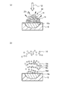
- FIGS. 7A and 7B are average images of plasma spheres in Experiment 4.
- FIGS. 7 (a) and 7 (b) are diagrams showing gray values for the pixels at AB in the images of FIGS. 7 (a) and 7 (b), respectively.
- FIG. 9A is a diagram showing the number of charged particles in the Faraday cup with respect to time in Experiment 5, and FIG. 9B is a diagram in which the time in FIG. 9A is converted into energy.
- FIG. 10A and FIG. 10B are schematic diagrams showing the diffusion process of charged particles from the considered plasma in vacuum.
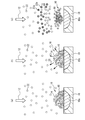
- FIG. 11A to FIG. 11C are schematic diagrams showing the diffusion process of charged particles from the plasma in the gas considered.
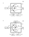
- FIG. 12A and FIG. 12B are block diagrams of the soft X-ray light source according to the first embodiment.
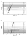
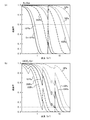
- FIGS. 13B are diagrams (part 1) showing the line intensity of UTA emission with respect to the wavelength of each element.
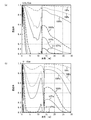
- FIGS. 14A and 14B are diagrams (part 2) showing the line intensity of UTA emission with respect to the wavelength of each element.
- FIG. 15A and FIG. 15B are diagrams (part 1) showing the transmittance of soft X-rays with respect to the wavelength.
- FIG. 16A and FIG. 16B are diagrams (part 2) showing the transmittance of soft X-rays with respect to the wavelength.
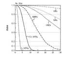
- FIG. 17 is a diagram (part 3) illustrating the transmittance of soft X-rays with respect to wavelength.
- FIG. 18 is a block diagram of an exposure apparatus according to the second embodiment.
- FIG. 19 is a block diagram of the microscope according to the third embodiment.
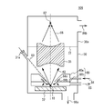
- FIG. 20 is a block diagram of a soft X-ray light source according to the fourth embodiment.
- FIG. 21A is a block diagram of a soft X-ray light source according to the fifth embodiment
- FIG. 21B is a plan view of a gas pressure adjustment unit.
- 22A is a plan view showing another example of the gas pressure adjusting unit and the target in Embodiment 4, and
- FIGS. 22B and 22C are cross-sectional views taken along line AA in FIG. 22A.
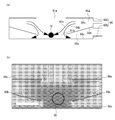
- FIG. FIG. 23A is a cross-sectional view of the simulated gas pressure adjustment unit
- FIG. 23B is a diagram illustrating an example of the simulation result.
- the experimental procedure is as follows. A target is placed in the chamber. A gas is introduced into the chamber. The target is irradiated with laser light. The spectrum of soft X-rays emitted from the target is measured using a spectroscope and a soft X-ray detector.
- Experiment 1 The conditions of Experiment 1 are shown below.
- Laser equipment Geko XII (Osaka University Laser Energy Research Center)
- Laser light wavelength 1053 nm
- Pulse energy 120J
- Pulse width 500 picoseconds
- Target Au (gold) or Al (aluminum)
- Chamber gas N 2 (nitrogen) gas
- Spectrometer Flat-field type grazing incidence spectrometer (grating groove spacing) 2400 / mm)
- Distance from spectrometer to detector 800mm
- the target to the detector is filled with gas at a constant pressure.
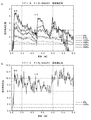
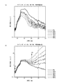
- FIG. 1A and FIG. 1B are diagrams showing the relative light emission intensity with respect to the wavelength in Experiment 1.
- the targets in FIGS. 1A and 1B are Au and Al, respectively.
- the relative light emission intensity is normalized by the light emission intensity at which the gas pressure at which no gas is introduced into the chamber is 0 Pa after correction of soft X-ray absorption by N 2 gas (hereinafter, absorption correction).
- the absorption correction was calculated from the soft X-ray transmittance of N 2 gas when the distance from the target to the detector was 1600 mm.
- the wavelength was calibrated with the K-shell absorption edge NK (approximately 3.0 nm) attributed to N 2 gas and the K-shell absorption edge CK (approximately 4.4 nm) attributed to the spectroscopic carbon.
- the relative emission intensity increases as the pressure of N 2 gas increases at a wavelength of 3 to 6 nm.
- the relative emission intensity is large on the long wavelength side of the NK end and the CK end, and the relative emission intensity is about 5 when the gas pressure is 400 Pa.
- the gas pressure is 267 Pa, and the relative emission intensity on the long wavelength side at the NK end is 12.
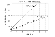
- FIG. 2 is a diagram showing the relative light emission intensity with respect to the relative pressure in Experiment 1.
- the relative emission intensity shown is the emission intensity at a wavelength of 3.2 nm.
- the relative pressure is such that the gas pressure is 67 Pa.
- the relative emission intensity increases linearly with respect to the gas pressure regardless of the type of target.
- Experiment 2 The conditions of Experiment 2 are shown below.
- Laser device Nd: YAG laser
- Laser light wavelength 1064 nm
- Pulse energy less than 1 J
- Pulse width 7 nanoseconds
- Target Au
- Gas in chamber N 2 gas
- Spectroscope Flat-field type oblique incidence spectroscope (diffraction grating groove interval 2400 lines / mm)
- Distance from target to spectrometer and detector 1000mm
- the target to the detector is filled with gas at a constant pressure.
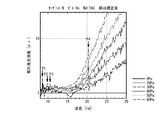
- FIG. 3A and FIG. 3B are diagrams showing the light emission intensity with respect to the wavelength in Experiment 2.
- FIG. FIGS. 3A and 3B show the emission intensities before and after absorption correction, respectively.
- the emission intensity is an arbitrary unit.
- the emission intensity after the absorption correction was calculated from the soft X-ray transmittance of N 2 gas when the distance from the target to the detector was 1000 mm.
- the emission intensity is lower than the gas pressure of 0 Pa when the gas pressure is 50 Pa to 99 Pa at a wavelength of 2 nm to 4.5 nm.
- the emission intensity is higher than that when the gas pressure is 0 Pa.
- the wavelength is 4.5 nm to 7 nm
- the emission intensity at a gas pressure of 0 Pa increases as the wavelength increases.
- the emission pressure becomes greater than 0 Pa when the gas pressure is 99 Pa or more.
- the emission intensity increases.
- the absorption correction is performed, the emission intensity becomes larger than the gas pressure of 0 Pa when the gas pressure is 100 Pa or more at 3 nm to 6 nm.
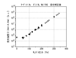
- FIG. 4 is a graph showing the light emission intensity with respect to the N 2 gas pressure in Experiment 2.
- the emission intensity is an integrated value (arbitrary unit) at a wavelength of 2.3 nm to 4.4 nm.
- the same experiment was performed three times, and the results of the three experiments are indicated by white squares, black circles, and white circles, respectively.
- the gas pressure is increased compared to 0 Pa, the emission intensity increases.
- the gas pressure is preferably 100 Pa or more, more preferably 150 Pa or more, and further preferably 200 Pa or more.
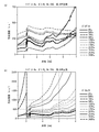
- FIG. 5 (a) and 5 (b) are diagrams showing the emission intensity with respect to the wavelength in Experiment 3.
- FIG. 5A and FIG. 5B show the emission intensities before and after absorption correction, respectively.
- FIG. 6 is a diagram showing the relative light emission intensity with respect to the wavelength after the absorption correction.
- the emission intensity is an integrated value of 100 pulses and is an arbitrary unit.
- the emission intensity after absorption correction was calculated from the soft X-ray transmittance of He gas when the distance from the target to the entrance slit of the spectrometer was 1000 mm.
- the emission intensity decreases. This is because soft X-rays are absorbed by He.
- the absorption correction is performed, the emission intensity increases as the gas pressure increases in the wavelength range of 8 nm to 30 nm. The behavior is different when the wavelength is 17 nm or less and 17 nm or more. A broad emission peak is observed at a wavelength of 8 nm to 17 nm.
- the gas pressure is 30 Pa or more, the emission intensity in this wavelength region increases linearly with an increase in gas pressure.
- the wavelength is from 17 nm to 30 nm, no clear peak structure is observed.
- the emission intensity in this wavelength region increases exponentially with increasing gas pressure.
- the light emission having a wavelength of 12 nm to 17 nm in FIG. 5B is shown in T. Putterich et al., Plasma Phys. Control. Fusion 50 (2008) 085016, from W 24+ to W 27+ when the plasma temperature is 1 keV. It is considered that the light emission.
- peaks P1 to P3 in FIG. 6 are respectively W 20+ , W 19+ , and W 18+ described in CS Harte, et al., J. Phys. B: At. Mol. Opt. It is considered that the light emission.
- the peak P4 is considered to be W 20+ emission described in C. Suzuki, et al., J. Phys. B: At. Mol. Opt. Phys., 44 175004.
- Light emission having a wavelength of 17 nm or more has a different behavior from light emission of 17 nm or less, the light emission mechanism is considered to be different.
- Light emission having a wavelength of 17 nm or more is considered to be, for example, bremsstrahlung of electrons.
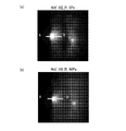
- FIG. 7 (a) and 7 (b) are average images of plasma spheres in Experiment 4.
- FIG. 7A and 7B the left circular white pattern is a plasma sphere.
- the white pattern on the right is a reflection image of the plasma sphere.
- the gas pressure is 0 Pa and 60 Pa, respectively.
- FIG. 7A is compared with FIG. 7B, the plasma sphere appears to be smaller in FIG. 7B.
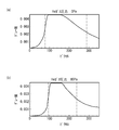
- FIGS. 7 (a) and 7 (b) are diagrams showing gray values for pixels at AB in the images of FIGS. 7 (a) and 7 (b), respectively.
- the pixel position where the gray value is half that of white (0.0045) is indicated by a broken line.
- the interval between the broken lines corresponds to the diameter of the plasma sphere.
- the diameter of the plasma sphere with a gas pressure of 60 Pa is about 80% of the gas pressure of 0 Pa.
- Example 5 Using the experimental apparatus of Experiment 3, the velocity of charged particles flying from the plasma was measured when no gas was introduced into the chamber (gas pressure was 0 Pa). A laser beam is incident along the normal direction of the target, and a Faraday cup is arranged at a position with a distance of 115 mm from the irradiation point on a straight line at an angle ⁇ with respect to the normal extending from the laser irradiation point on the target surface. . The time response immediately after laser beam irradiation of incoming charged particles was measured in synchronization with the laser beam pulse.
- FIG. 9A is a diagram showing the number of charged particles in the Faraday cup with respect to time in Experiment 5.
- FIG. 9A shows the number of charged particles obtained from the measured value of the Faraday cup as an absolute value.
- FIG. 9B is a diagram in which the time in FIG. 9A is converted into energy. The results show that the angle ⁇ is 23.7 °, 43.7 °, 53.7 °, and 76.0 °.
- FIGS. 9A and 9B four peaks Pa, Pb, Pc, and Pd are observed.
- the peak symbols Pb, Pc, and Pd in FIGS. 9A and 9B represent the corresponding peaks, respectively.
- Calculation of the velocity of charged particles from the time of each peak is as follows. Pa: 3.2 ⁇ 10 5 m / sec Pb: 2.5 ⁇ 10 4 m / sec Pc: 8.9 ⁇ 10 3 m / sec Pd: 3.3 ⁇ 10 3 m / sec
- the peaks Pa, Pb, Pc, and Pd are 50000 eV, 620 eV, 70 eV, and 12 eV, respectively.
- the peak Pa energy is about two orders of magnitude higher than the blackbody radiation temperature peak value (180 eV to 600 eV) expected from the input energy, and is too high for the input energy. This signal is not considered.
- the peak Pa when the peak Pa is considered as a signal due to electrons and converted to energy, it becomes 0.3 eV, which is a value that can be taken sufficiently as electrons in plasma. From the above, it is considered that the peak Pa corresponds to electrons, and the peaks Pb, Pc and Pd correspond to W ions having different valences.
- FIG. 10A and FIG. 10B are schematic diagrams showing the diffusion process of charged particles from the considered plasma in vacuum.
- FIG. 10A when the target 10 is irradiated with the laser beam 12, a part 10a of the target 10 is melted.
- a plasma sphere 18 of the material of the target 10 (for example, W) is generated.
- the plasma sphere 18 includes electrons 14 and target material ions 16.
- the soft X-ray 20 is emitted from the plasma sphere 18.
- the charged particles that have obtained energy from the laser beam scatter in the vacuum.
- some of the electrons 14 that have left the constraints of the ions 16 a to 16 d scatter the fastest, and ions 16 a to 16 d having different valences scatter later than the electrons 14.
- the ions 16a to 16d have different valences, and the speed varies depending on the valence.
- the outermost side becomes the electron 14 and the ions 16a to 16d become the inner side.
- FIG. 11A to FIG. 11C are schematic diagrams showing the diffusion process of charged particles from the plasma in the gas considered.
- gas molecules 22 exist in the chamber.
- FIG. 11 (b) soft X-rays 20 are emitted from the plasma sphere 18 after about picoseconds have elapsed from the irradiation of the laser beam 12.
- FIG. 11C when nanoseconds elapse after the soft X-rays 20 are emitted, the gas molecules 22 are irradiated to the soft X-rays 20, and the gas molecules 22 are ionized by the photoelectric effect.
- the ions 22a and electrons 22b are generated by ionization of the gas molecules 22.
- Coulomb interaction works between the ions 22 a and the electrons 22 b and the electrons 14.
- the electrons 14 are cooled, and the scattering speed of the electrons 14 is suppressed.
- scattering of ions 16 in the plasma sphere 18 is also suppressed.
- the plasma sphere 18 contracts in the gas atmosphere.
- the electrons 14 and the ions 16 move so as to satisfy the principle of minimum heat generation.
- the electrons 14 release energy in the form of light or the like to decrease the movement speed and increase the electron density in the plasma sphere 18.
- the ions 16 cannot emit energy in the form of light, a part of the kinetic energy is converted into internal energy and the valence is increased. As a result, the density of the ions 16 increases. In other words, in the compressed plasma sphere 18, it is considered that the electron density and the ion density increase simultaneously.
- Equation 3 the energy of soft X-rays with wavelength ⁇ emitted from the plasma E ( ⁇ ) is expressed by Equation 3.
- Equation 3 h is Planck's constant, and ⁇ is the frequency of soft X-rays.
- the plasma generated by the pulsed laser beam expands and loses energy.
- the radial width L of the plasma emission region is inversely proportional to the plasma absorption coefficient ⁇ .
- the absorption coefficient alpha using proportional coefficient a, degree of ionization Z and electron density n e ⁇ aZn e 2
- the width L of the light emitting region is the reciprocal of the absorption coefficient ⁇ . Therefore, L is expressed by Equation 4.
- Equation 5 the energy E ( ⁇ ) of the soft X-ray becomes Equation 5.
- Ion density N i in Equation 3 and 5 increases the emit an electron density n e, to increase the emission intensity of the soft X-rays, inhibit the expansion of the plasma ion density N i, emit an electron density n It can be seen that e should be increased.
- the size of the plasma sphere 18 contracts when the target 10 is in a gas atmosphere. This increases the ion density and the electron density. Therefore, the ion density N i in Equation 3 and 5, increases the emit an electron density n e, it is considered that the emission intensity of the soft X-rays is increased. According to this consideration, it can be seen that the increase in emission intensity due to gas does not depend on the type of target, the type of gas, and the type of laser light.
- FIG. 12A and FIG. 12B are block diagrams of the soft X-ray light source according to the first embodiment.
- FIG. 12A shows a case where the target is solid
- FIG. 12B shows a case where the target is liquid.
- the soft X-ray light source 100 includes a chamber 30, a target 32, an optical system 34, a laser device 36, a gas supply unit 38, and a vacuum pump 40.
- the chamber 30 is provided with windows 31a and 31b.
- the target 32 is installed in the chamber 30.
- the laser device 36 emits a laser beam 60.
- the laser beam 60 is applied to the target 32 through the window 31a.
- Soft X-rays 62 emitted from the target 32 are collected by the optical system 34.
- the soft X-ray 62 is emitted from the chamber 30 through the window 31b.
- the gas supply unit 38 supplies gas into the chamber 30 and maintains the gas pressure in the chamber 30 constant.
- the vacuum pump 40 exhausts the gas in the chamber 30.
- the target supply unit 42 supplies droplets of the target 32 into the chamber 30.
- the target 32 falls due to gravity.
- the laser beam 60 is applied to the target 32 while the target 32 is falling.
- the target recovery unit 44 recovers the dropped target 32.
- Other configurations are the same as those in FIG. 12 (b).
- the laser device 36 generates plasma including an element included in the target 32 by irradiating the target 32 with the laser light 60, and emits soft X-rays 62 from the plasma.
- the chamber 30 accommodates the target 32 therein, and when the laser device 36 irradiates the target 32 with the laser beam 60, the gas pressure of the internal gas is set to 10 Pa or more and less than atmospheric pressure. That is, the gas supply unit 38 supplies the gas so that the periphery of the target 32 has a gas pressure of 10 Pa or more and less than atmospheric pressure when the target 32 is irradiated with the laser beam 60.
- the soft X-ray light sources 100 and 102 the conversion efficiency from the laser beam 60 to the soft X-ray 62 can be increased.
- the target 32 may be a gas.
- the gas pressure of the gas inside the chamber containing the target gas may be 10 Pa or more and atmospheric pressure or less. It is preferable that the partial pressure of the gas not including the target gas is 10 Pa or more.
- plasma may be generated by irradiating a solid or liquid target with laser light in a pre-pulse, making a part or all of the target into plasma, and further irradiating the plasma target with laser light.
- the wavelength of the laser beam 60 is not particularly limited as long as it generates plasma.
- the wavelength of the laser beam 60 can be, for example, about several hundred nm to several tens of ⁇ m.
- As the laser device 36 a YAG laser device or a CO 2 laser device capable of high output can be used.
- the laser beam 60 is a pulsed laser beam.
- the pulse width is preferably longer than the time for the soft X-rays 20 to reach the gas molecules 22 in FIG. Assuming that the range in which the gas molecules 22 exist is about 30 cm, the pulse width is preferably 1 nanosecond or more, more preferably 2 nanoseconds or more, and further preferably 5 nanoseconds or more.
- the pulse width is preferably 500 nanoseconds or less, and more preferably 100 nanoseconds or less.
- the wavelength of the soft X-ray 62 is generally 0.3 nm to 200 nm. In Experiment 1 to Experiment 3, the wavelength of the soft X-ray is 2 nm to 30 nm. The wavelength range of 2 nm to 30 nm is also called extreme ultraviolet light. The wavelength of the soft X-ray can be arbitrarily set according to the purpose.
- the light emission mechanism from plasma is roughly classified into three.
- the first is blackbody radiation.
- Blackbody radiation does not depend on the target type.
- the emission intensity can be increased by increasing the plasma temperature and / or plasma density.
- the second is light emission by braking radiation.
- Braking radiation is generated when acceleration is applied to charged particles by Coulomb force between charged particles, such as when electrons in plasma pass around ions. Braking radiation does not depend on the type of target.
- the third is light emission by electronic transition.
- Light emission by electronic transition is most easily used because of its high intensity even at short wavelengths. Since the ionization energy differs depending on the atomic number and the valence of ions, a plurality of emission lines can be observed in the soft X-rays emitted from the plasma.
- the energy of the emission line from the K-shell, L-shell and M-shell in monovalent ions from Li (lithium) with atomic number 3 to 94 Am (americium) is, for example, A. Thompson et al., "X-ray Data Booklet ”(Lawrence Berkely National Laboratory, Univ. Of Cal., Berkeley, CA 94720 (2009)) Section 1.2.
- UTA emission is preferably used.
- FIG. 13A to FIG. 14B are diagrams showing the line intensity of UTA emission with respect to the wavelength of each element described in this document.
- FIG. 13A shows In (indium), Sn (tin), Sb (antimony), Te (tellurium), I (iodine), Xe (xenon), Cs (cesium) having atomic numbers of 49 to 59, It is a figure which shows the linear intensity
- 13B shows Nd (neodymium), Pm (promethium), Sm (samarium), Eu (europium), Gd (gadolinium), Tb (terbium), Dy (dysprosium) having atomic numbers of 60 to 70, It is a figure which shows the linear intensity
- FIG. 14A shows Lu (lutetium), Hf (hafnium), Ta (tantalum), W (tungsten), Re (rhenium), Os (osmium), Ir (iridium) having atomic numbers of 71 to 81, It is a figure which shows the linear intensity
- the UTA emission wavelength decreases as the atomic number increases.
- the material of the target 32 can be appropriately selected according to the emission wavelength.
- the target 32 is preferably solid or liquid in the chamber 30. From the viewpoint of the wavelength of UTA emission and the target 32 being solid or liquid, the material of the target 32 is preferably as follows.
- EUVL Extreme Ultraviolet Lithography
- soft X-ray having a wavelength of around 13.5 nm for example, 13 nm to 14 nm is used.
- the wavelength of 13.5 nm is indicated by a solid line
- the wavelengths of 13 nm and 14 nm are indicated by dotted lines.
- As a target material having a wavelength range of 13 nm to 14 nm In, Sn, Sb, Te, I or the like is preferable.
- wavelengths 6 nm and 7 nm are indicated by dotted lines.
- Nd, Sm, Eu, Gd, Tb, Dy, Ho, Er, Tm, Yb or the like is preferable as a target material having a wavelength range of 6 nm to 7 nm.
- the range from 4.5 nm to 5 nm is called a carbon window.
- This range is a range on the long wavelength side of the K-shell absorption edge of carbon. Because of the longer wavelength than the K-shell absorption edges of oxygen, nitrogen and carbon, it is relatively transparent to all biological elements. For this reason, it becomes a soft X-ray suitable for observation of light element compounds such as cells and polymers.
- the wavelength of 4.5 nm and the wavelength of 5.0 nm are shown by a one-dot chain line.
- Lu, Hf, Ta, W, Re, Os, Ir, Pt, Au, Hg, Tl, or the like is preferable.
- the range from 2.3 nm to 4.5 nm is called the water window.
- This range is the range between the K-shell absorption edges of carbon and oxygen. Since it has a shorter wavelength than the K-shell absorption edge of oxygen, it is transparent to water and opaque to carbon. For this reason, it becomes a soft X-ray suitable for observation of cells or the like.
- the wavelengths 2.3 nm and 4.5 nm are shown by dotted lines in FIGS.
- Lu, Hf, Ta, W, Re, Os, Ir, Pt, Au, Hg, Tl, Pb, Bi, or the like is preferable.
- a material preferable as a gas will be considered.
- the increase in emission intensity does not depend on the type of gas.
- a gas that absorbs soft X-rays is not preferable.
- the transmittance increases on the long wavelength side of the absorption edge. For this reason, it is preferable to select the gas so that the absorption edge is on the short wavelength side of the soft X-ray wavelength.
- a gas composed of molecules with poorer spatial symmetry in addition to the absorption edge being on the short wavelength side of the soft X-ray wavelength.
- a polyatomic gas is preferable to a monoatomic gas such as a rare gas.
- a gas containing a plurality of types of elements is preferable to a single element gas such as H 2 gas and N 2 gas.
- the gases shown from the viewpoint of the absorption edge and the viewpoint of spatial symmetry can be used in a mixed manner if they are not reactive with each other. As a result, when a gas that can be expected to have a stronger electron cooling effect cannot be used for safety reasons, it can be used by changing to a safer state by mixing.
- He having no absorption edge or Kr (krypton) having an M-shell absorption edge of about 13.2 nm is preferable.
- a gas containing Si (silicon) having an L shell absorption edge of 12.4 nm is preferable.
- the gas containing Si include SiCl 4 , SiF 4 , SiH 4 , SiH 3 (CH 3 ), SiH 2 (CH 3 ) 2 , SiH (CH 3 ) 3 , Si 2 H 6 , SiHCl 3 , SiH 2 Cl 2.
- a silane-based gas such as Si (OCH 3 ) 4 .
- a gas containing P (phosphorus) having an L-shell absorption edge of about 9.2 nm is preferable.
- the gas containing P is, for example, PF 3 , PF 5 , PCl 3 , PCl 5 , PH 3, or POCl 3 .
- a gas containing Sn (tin) having an N-shell absorption edge of 9.0 nm is preferable.
- the gas containing Sn is, for example, SnH 4 or SnCl 4 .
- a gas containing S (sulfur) having an L-shell absorption edge of about 7.6 nm is preferable.
- the gas containing S is, for example, S 2 H, SF 6 or SO 2 .
- a gas containing B (boron) having a K-shell absorption edge of 6.6 nm is preferable.
- the gas containing B is, for example, BBr 3 , BCl 3 , BF 3 or B 2 H 6 .
- a gas containing Mo (molybdenum) having an N-shell absorption edge of 5.4 nm is preferable.
- the gas containing Mo is, for example, MoF 6 or MoCl 5 .
- a gas containing C (carbon) having a K-shell absorption edge of about 4.4 nm is preferable.
- Gas containing C for example CH 4, C 2 H 2, C 2 H 4, C 2 H 8, C 3 H 6, C 4 H 6, C 4 H 10, C 3 H 8, C 3 H 6, C 6 H 6 , (CH 3 ) 20 , CO 2 or fluorocarbons.
- a gas containing N (nitrogen) having a K-shell absorption edge of about 3.0 nm is preferable.
- the gas containing N is, for example, N 2 , ND 3 , NF 3 , NH 3 , NO, N 2 O, NO 2, or N (CH 3 ) 3 .
- a gas containing O (oxygen) having a K-shell absorption edge of about 2.3 nm is preferable.
- the gas containing O is, for example, CO 2 , NO, N 2 O, NO 2 , SO 2 or fluorocarbons.
- the transmittance is high for many gases.
- an inert gas can be used.
- the inert gas is, for example, He (helium), Ne (neon), argon (Ar), Kr (krypton), Xe (xenon), Rn (radon), N 2 , CO 2 or fluorocarbons.
- a gas containing an element having no clear absorption edge can be used regardless of the wavelength of soft X-rays.
- An element that does not have a clear absorption edge is, for example, He or H (hydrogen).
- the gas is preferably at least one of a gas containing silicon, a gas containing Mo, a helium gas, and a hydrogen gas.
- the gas is preferably at least one of a gas containing carbon, a gas containing boron, helium gas, and hydrogen gas.
- the gas is preferably at least one of carbon-containing gas, helium gas, and hydrogen gas.
- the gas is preferably at least one of a gas containing oxygen, a gas containing nitrogen, a helium gas, and a hydrogen gas.
- the lower limit of the gas pressure is such a gas pressure that the light emission intensity of soft X-rays is higher than in vacuum.
- a gas pressure is realized by setting the gas pressure so that the plasma sphere formed by the plasma is smaller than the plasma sphere in the vacuum, as shown in FIGS. it can.
- the size (diameter) of the plasma sphere in the gas atmosphere is preferably 95% or less, more preferably 90% or less of the plasma sphere in vacuum.
- the gas pressure is preferably 10 Pa or more, more preferably 50 Pa or more, and even more preferably 100 Pa or more.
- the upper limit of the gas pressure is in a range where soft X-ray absorption is small.
- the intensity I ( ⁇ , p) of the soft X-ray after passing through the gas is a function of the wavelength ⁇ of the soft X-ray and the gas pressure p. If the emission intensity I 0 ( ⁇ , 0) in vacuum, the amplification factor ⁇ ( ⁇ , p) of the emission intensity due to the introduction of gas, and the transmittance T ( ⁇ , p) of soft X-rays in the gas, the intensity I ( ⁇ , p) is expressed by the following equation.
- I ( ⁇ , p) I 0 ( ⁇ , 0) ⁇ ⁇ ( ⁇ , p) ⁇ T ( ⁇ , p) From Experiment 1 to Experiment 3, assuming that ⁇ ( ⁇ , p) is about 10, in order to make I ( ⁇ , p) larger than I 0 ( ⁇ , 0), T ( ⁇ , p) is 0.1. The above is preferable. In order to further increase I ( ⁇ , p), it is preferable that T ( ⁇ , p) is 0.6 or more.
- the transmittance T ( ⁇ , p) depends on the distance that the soft X-ray passes through the gas. In order to prevent soft X-rays from being absorbed by gas, it is effective to shorten the distance that soft X-rays pass through the gas. However, considering the optical system and the like, this distance is at least about 10 cm. Therefore, the transmittance when soft X-rays passed through 10 cm of gas was calculated by changing the gas pressure of various gases.
- FIG. 15A to FIG. 17 are diagrams illustrating the soft X-ray transmittance with respect to the wavelength, and are diagrams illustrating the soft X-ray transmittances of N 2 , CHClF 2 , SiH 4 , Kr, and He, respectively.
- N 2 , CHClF 2 , SiH 4 and Kr are examples of gas having an absorption edge
- He is an example having no absorption edge.
- the gas pressure of N 2 gas is about 100 Pa or less and about 30 Pa or less, respectively.
- the wavelength range where the transmittance is 0.1 or more is 1.5 nm or less, or 3 nm to 5 nm.
- the wavelength range where the transmittance is 0.1 or more is 1 nm or less, or 3 nm to 3.6 nm.
- the gas pressure is preferably about 1000 Pa or less and about 700 Pa or less, respectively, in order to set the transmittance to 0.1 or more and 0.6 or more in the vicinity of the water window on the long wavelength side of the N K-shell absorption edge.
- the gas pressure is preferably about 800 Pa or less and about 500 Pa or less, respectively.
- the gas pressure is preferably about 300 Pa or less and about 80 Pa or less, respectively.
- the K-shell absorption edge of F is about 1.8 nm
- the K-shell absorption edge of C is about 4.4 nm
- the L-shell absorption edge of Cl is about 6.2 nm.
- the gas pressure of the CHClF 2 gas is about 50 Pa or less and about 10 Pa or less, respectively.
- the gas pressure is preferably about 200 Pa or less and about 50 Pa or less, respectively, in order to make the transmittance in the vicinity of the water window 0.1 or more and 0.6 or more.
- the gas pressure is preferably about 200 Pa or less and about 100 Pa or less, respectively. In order to set the transmittance to 0.1 or more and 0.6 or more in the wavelength range of 13 nm to 14 nm, the gas pressure is preferably about 100 Pa or less and about 30 Pa or less, respectively.
- the vicinity of 12.4 nm is the L shell absorption edge of Si.
- the gas pressure of SiH 4 is preferably about 2000 Pa or less and about 500 Pa or less, respectively.
- the gas pressure is preferably about 1000 Pa or less and about 400 Pa or less, respectively.
- the gas pressure is 5000 Pa or less and the transmittance is 0.6 or more.
- the transmittance is 0.1 or more at 5000 Pa or less.
- the gas pressure is 500 Pa or less and the transmittance is 0.6 or more.
- the gas pressure in a gas having an absorption edge, when the wavelength of soft X-rays is located on the long wavelength side of the absorption edge, the gas pressure is preferably 1000 Pa or less, more preferably 500 Pa or less. Preferably, 200 Pa or less is more preferable. As shown in FIG. 17, in a gas having no K-shell absorption edge, the gas pressure may be less than atmospheric pressure in the vicinity of the water window. The gas pressure may be 1000 Pa or less even in the wavelength range of 13 nm to 14 nm.
- the gas pressure around the target 32 is 10 Pa or more and less than atmospheric pressure, preferably 10 Pa or more and 1000 Pa or less, more preferably 50 Pa or more and 500 Pa or less.
- the second embodiment is an exposure apparatus using the soft X-ray light source of the first embodiment.
- FIG. 18 is a block diagram of an exposure apparatus according to the second embodiment.
- the exposure apparatus 104 includes a soft X-ray light source 100 or 102, a chamber 50, and optical systems 52 and 54.
- the chamber 50 is maintained in a vacuum having a degree of vacuum that does not absorb soft X-rays.
- the optical system 52 condenses the soft X-rays 62 emitted from the soft X-ray light source 100 or 102 on the mask 56.
- the optical system 54 focuses the soft X-rays reflected by the mask 56 on the wafer 58. As a result, the pattern on the mask 56 is transferred to the wafer 58.
- the output of a soft X-ray light source in EUVL using a wavelength of 13.5 nm is required to be 250 W, for example.
- the conversion efficiency can be increased and the output of the soft X-ray light source can be increased.
- the soft X-ray light source 100 or 102 according to the first embodiment can be used in an exposure apparatus.
- the third embodiment is a microscope using the soft X-ray light source of the first embodiment.
- FIG. 19 is a block diagram of the microscope according to the third embodiment.
- the microscope 105 includes a soft X-ray light source 100 or 102, a chamber 70, optical systems 72 and 74, and a two-dimensional detector 76.
- the inside of the chamber 70 is maintained in a vacuum having a degree of vacuum that does not absorb soft X-rays.
- the optical system 72 condenses the soft X-rays 62 emitted from the soft X-ray light source 100 or 102 onto the sample 78 that is desired to be observed as the soft X-rays 63.
- the soft X-ray 64 transmitted or reflected by the sample 78 is collected by the optical system 74 on the two-dimensional detector 76. Thereby, a transmission image or a reflection image of the sample is enlarged and projected onto the two-dimensional detector 76.
- Microscopes using soft X-rays have a spatial resolution that is more than an order of magnitude higher than conventional visible light microscopes, and the element distribution of substances can be obtained without staining by the inner shell absorption edge. It is requested. However, since a strong soft X-ray light source is required, a method using radiant light as a light source has been mainly used. As in the third embodiment, the soft X-ray light source 100 or 102 according to the first embodiment can be used in a soft X-ray microscope.
- the soft X-ray light source 100 or 102 according to the first embodiment can be used for measuring instruments such as an emission spectroscopic device, an absorption spectrophotometer, a photoelectron spectroscopic device, in addition to the exposure apparatus and the soft X-ray microscope.
- instruments such as an emission spectroscopic device, an absorption spectrophotometer, a photoelectron spectroscopic device, in addition to the exposure apparatus and the soft X-ray microscope.
- biological cells can be observed and analyzed by applying the soft X-ray light source of Embodiment 1 to the wavelength of a water window or a carbon window.
- FIG. 20 is a block diagram of a soft X-ray light source according to the fourth embodiment.
- the soft X-ray light source 106 includes chambers 30 and 30 a, an optical system 35, and a gas pressure adjustment unit 80.
- the chamber 30 contains a solid target 32.
- the gas in the chamber 30 is exhausted 86a by a vacuum pump.
- the laser beam incident through the window 31a is applied to the target 32.
- Soft X-rays 62 are emitted from the plasma sphere 18.
- a blocking wall 37 is provided between the chamber 30 a and the chamber 30.
- the gas in the chamber 30a is exhausted 86b by a vacuum pump.
- An optical system 35 is embedded in the blocking wall 37.
- the soft X-rays 62 emitted from the plasma sphere 18 are converged by the optical system 35 and focused on the focus position 82 in the chamber 30a.
- the optical system 35 an optical system having a conductance lower than that in the open state is used. This increases the gas pressure difference between the chambers 30 and 30a.
- a capillary optical system is used as the optical system 35 having a small conductance.
- a donut-shaped gas pressure adjusting unit 80 (for example, a gas pressure adjuster) is provided around the target 32.
- the upper surface of the gas pressure adjusting unit 80 is inclined so as not to obstruct the laser beam 60 and the soft X-ray 62.
- the gas pressure adjusting unit 80 includes a gas introduction unit 80a (for example, a gas introduction guide) and a gas exhaust unit 80b (for example, a gas exhaust guide).
- the inside of the gas introduction unit 80a is a cavity filled with the gas 84.
- the gas introduction unit 80a introduces a part of the gas 84a of the gas 84 around the region of the target 32 to which the laser beam 60 is irradiated (the region that becomes the plasma sphere 18 thereafter).
- the gas exhaust unit 80b is provided on the target 32 side of the gas introduction unit 80a.
- the gas exhaust unit 80b exhausts 85 part of the gas 84 by using a vacuum pump.
- the gas pressure adjusting unit 80 introduces gas around the target 32 to be irradiated with the laser beam 60 in the chamber 30. Thereby, the gas pressure around the target 32 is maintained higher than the gas pressure of at least a part of the path of the laser beam 60 and the soft X-ray 62.
- the gas pressure adjusting unit 80 sets the gas pressure around the region irradiated with the laser light 60 in the target 32 to the gas pressure shown in the first embodiment (for example, 10 Pa or more and less than atmospheric pressure).
- the gas pressure of at least a part of the path of the soft X-ray 62 in the chamber 30 is set lower than the gas pressure around the region of the target 32 where the laser beam 60 is irradiated.
- the lowest gas pressure in the path of the soft X-ray 62 in the chamber 30 is preferably 1/2 or less of the gas pressure around the plasma sphere 18, more preferably 1/5 or less, and more preferably 1/10 or less.
- the portion lower than the gas pressure around the plasma sphere 18 is preferably 1 ⁇ 2 or more of the entire path, and more preferably 9/10 or more.
- the gas introduction unit 80 a introduces gas around the plasma sphere 18, and the gas exhaust unit 80 b exhausts gas from the periphery of the plasma sphere 18. Thereby, the gas pressure around the plasma sphere 18 can be made higher than the gas pressure in the path of the soft X-ray 62.
- the gas pressure adjusting unit 80 may adjust the gas pressure in the chamber 30 by other methods.
- the soft X-ray 66 is introduced into the other chamber 30 a from the chamber 30, and the gas pressure inside the chamber 30 a is lower than the gas pressure in the path of the soft X-ray 62 in the chamber 30. Thereby, attenuation of the soft X-ray 66 in another chamber 30a can be suppressed.
- the gas pressure inside the chamber 30a is preferably lower than the lowest gas pressure among the paths of the soft X-rays 62, more preferably 1 ⁇ 2 or less of the lowest gas pressure among the paths of the soft X-rays 62, and 1/10 The following is more preferable.
- An optical system 35 for introducing soft X-rays 66 into another chamber 30a is provided between the chambers 30 and 30a.
- the soft X-rays 62 that diverge from the target 32 can be introduced into the chamber 30a as convergent light or parallel light. Since most of the soft X-rays 62 that diverge from the target 32 are converged or collimated, the numerical aperture of the optical system 35 is large.
- the optical system 35 has a conductance lower than that in the open state. Thereby, since the optical system 35 is difficult to pass gas, the gas pressure in the chamber 30 a can be made smaller than that in the chamber 30. Therefore, attenuation of the soft X-ray 66 can be suppressed.
- the conductance lower than the open state means that the conductance is lower than the opening provided in the blocking wall 37 for providing the optical system 35, for example.
- a capillary optical system uses a capillary tube to narrow a path through which soft X-rays pass. For this reason, the conductance of gas also becomes low.
- the optical system 35 may be other than the capillary optical system as long as it is an optical system that reduces gas conductance.
- FIG. 21A is a block diagram of the soft X-ray light source according to the fifth embodiment
- FIG. 21B is a plan view of the gas pressure adjustment unit 80.
- a blocking wall 37a having an opening 33 through which the soft X-ray 66 passes is provided immediately before the focus position 82 in the chamber 30a.
- the chamber 30a is divided into rooms 39a and 39b by the blocking wall 37a.
- the gas in the room 39a on the optical system 35 side of the blocking wall 37a and the gas in the room 39b on the focus position 82 side are exhausted 86c and 86b from the exhaust port by a vacuum pump, respectively.
- the upper surface of the gas pressure adjusting unit 80 is not provided with an inclined surface.
- An opening 81 is provided on the upper surface of the gas pressure adjusting unit 80 so as not to obstruct the laser beam 60 and the soft X-ray 62.
- the gas 84 a is uniformly introduced toward the plasma sphere 18 from 360 ° around the plasma sphere 18. A part of the gas 84, gas 84 c, diffuses into the chamber 30 from the opening 81.
- the lower surface of the gas pressure adjusting unit 80 is provided near the target 32 so as not to entrain gas. Other configurations are the same as those of the fourth embodiment, and the description thereof is omitted.
- FIGS. 22A and 22B are cross-sectional views taken along line AA in FIG. 22A.
- the target is a liquid or a gas
- the target liquid or gas moves from the target supply unit 92a to the target recovery unit 92b as indicated by an arrow 91 (for example, drops). To do).
- the target is irradiated with laser light, and a plasma sphere 18 is generated.
- the bottom 87 of the gas pressure adjusting unit 80 is closed.
- Other configurations are the same as those in FIGS. 21A and 21B, and a description thereof will be omitted.
- FIG. 23A is a cross-sectional view of the simulated gas pressure adjustment unit 80
- FIG. 23B is a diagram illustrating an example of the simulation result.
- the gas pressure adjusting unit 80 has blocking walls 88a to 88c.
- the gas introduction unit 80a has a cavity 85a formed between the blocking walls 88a and 88b.
- the gas introduction unit 80a introduces the gas 84a around the plasma sphere 18 through the cavity 85a.
- the gas exhaust unit 80b has a cavity 85b formed between the blocking walls 88b and 88c.
- the gas exhaust unit 80b exhausts the gas 84b from the periphery of the plasma sphere 18 through the cavity 85b.
- the blocking walls 88a and 88b are provided with openings 81a and 81b.
- the blocking wall 88c corresponds to the upper surface of the target 32 in FIG. 21 (a) and the bottom 87 in FIGS. 22 (b) and 22 (c).
- the blocking wall 88a is substantially parallel to the blocking wall 88c (the upper surface of the target 32).
- the blocking wall 88b is inclined downward on the plasma sphere 18 side. That is, the interval between the blocking walls 88a and 88b is wider on the plasma sphere 18 side.
- the space between the blocking walls 88b and 88c is narrower on the plasma sphere 18 side.
- the gas was nitrogen gas at room temperature.
- the direction of the arrow indicates the gas flow direction, and the length of the arrow indicates the gas flux.
- the shading indicates the gas pressure, and the dark area indicates that the gas pressure is high.
- the gas pressure is high, the strength of the soft X-ray 62 can be increased.
- the gas pressure adjustment unit 80 uses the gas flux around the region where the target 32 is irradiated with the laser light 60 as the gas flux most in the soft X-ray path in the chamber 30. Make it smaller than the flux at the large point. Thereby, the plasma sphere 18 can be shielded stably.
- the gas flux around the region where the target 32 is irradiated with the laser beam 60 is preferably less than or equal to 1 ⁇ 2 of the flux at the highest gas flux in the soft X-ray path in the chamber 30. 1/5 or less is more preferable.
- the gas introduction unit 80a includes a cavity 85a (first cavity) formed between a blocking wall 88a (first wall) and a blocking wall 88b (second wall) surrounding the plasma sphere 18.
- the gas exhaust unit 80b is disposed from the periphery of the plasma sphere 18 via a cavity 85b (second cavity) formed between the shielding wall 88b (third wall) surrounding the plasma sphere 18 and the shielding wall 88c (fourth wall).
- the gas 84b is exhausted.
- the distance between the blocking walls 88a and 88b increases as the distance from the plasma sphere 18 approaches.
- the distance between the blocking walls 88b and 88c becomes narrower as the circumference of the plasma sphere 18 is approached.
- the flux around the plasma sphere 18 can be reduced and the gas pressure can be increased.
- the blocking wall 88b may have a function of the second wall and the third wall. Further, the second wall and the third wall may be different walls.
- exhaust ports are provided on the optical system 35 side and the focus position 82 side of another chamber 30a. Thereby, a gas pressure difference can be provided in the path of the soft X-ray 66 in another chamber 30a. Therefore, attenuation of soft X-rays can be suppressed.
- the target 32 may be solid, liquid, or gas.
- the soft X-ray light source of Embodiments 4 and 5 may be used for the exposure apparatus of Embodiment 2 or the microscope of Embodiment 3.
Landscapes
- Physics & Mathematics (AREA)
- Engineering & Computer Science (AREA)
- Plasma & Fusion (AREA)
- General Engineering & Computer Science (AREA)
- High Energy & Nuclear Physics (AREA)
- Chemical & Material Sciences (AREA)
- Analytical Chemistry (AREA)
- Optics & Photonics (AREA)
- General Physics & Mathematics (AREA)
- Exposure And Positioning Against Photoresist Photosensitive Materials (AREA)
- X-Ray Techniques (AREA)
- Plasma Technology (AREA)
Abstract
ターゲット32にレーザ光60を照射することにより前記ターゲットに含まれる元素を含むプラズマを生成し、前記プラズマから軟X線62を放射させるレーザ装置36と、前記ターゲットを内部に収納し、前記レーザ装置が前記ターゲットに前記レーザ光を照射するときに、前記内部のガスのガス圧力を10Pa以上かつ大気圧未満とするチャンバ30と、を具備する軟X線光源。
Description
本発明は、軟X線光源、露光装置および顕微鏡に関し、例えばレーザ光をターゲットに照射することにより軟X線を放射させる軟X線光源、露光装置および顕微鏡に関する。
極紫外(EUV:Extreme Ultraviolet)光または軟X線の光源として、レーザ生成プラズマ(LPP:Laser Produced Plasma)光源が知られている(例えば特許文献1~4)。LPP光源は、ターゲット材料にレーザ光を照射することでターゲット材料がプラズマ化し、このプラズマから放射される極紫外光または軟X線を利用する光源である。
EUV光源において、チャンバ内に緩衝ガスを導入することによりデブリと呼ばれる飛散粒子が光学系を汚染または損傷することを抑制することが知られている(例えば特許文献5)。緩衝ガスをプラズマ放電中のチャンバ内に導入することで、プラズマにより生成されたイオンを遅くし光学系等への損傷を抑制することが知られている(例えば特許文献6)。
LPP光源では、高出力化が求められている。このため、照射するレーザ光のエネルギーに対し出射される軟X線のエネルギーを示す変換効率を高めることが求められている。特許文献5および6には、光学系等の汚染や損傷を抑制するためにチャンバ内に緩衝ガスを導入することが記載されている。しかし、プラズマから放射される軟X線自体を高出力化する方法については記載されていない。
本発明は、上記課題に鑑みなされたものであり、軟X線光源において、レーザ光から軟X線への変換効率を高めることを目的とする。
本発明は、ターゲットにレーザ光を照射することにより前記ターゲットに含まれる元素を含むプラズマを生成し、前記プラズマから軟X線を放射させるレーザ装置と、前記ターゲットを内部に収納し、前記レーザ装置が前記ターゲットに前記レーザ光を照射するときに、前記内部のガスのガス圧力を10Pa以上かつ大気圧未満とするチャンバと、を具備することを特徴とする軟X線光源である。
上記構成において、前記ターゲットのうち前記レーザ光が照射される領域の周囲の前記ガスのガス圧を10Pa以上かつ大気圧未満とし、前記チャンバ内の前記軟X線の経路の少なくとも一部のガス圧を前記領域の周囲のガス圧より低くするガス圧調整ユニットを具備する構成とすることができる。
上記構成において、前記ガス圧調整ユニットは、前記領域の周囲の前記ガスの流束を、前記チャンバ内の前記軟X線の経路のうち最も前記ガスの流束の大きい箇所の流束より小さくする構成とすることができる。
上記構成において、前記ガス圧調整ユニットは、前記領域の周囲に前記ガスを導入するガス導入ユニットと、前記領域の周囲から前記ガスを排気するガス排気ユニットと、を有する構成とすることができる。
上記構成において、前記ガス導入ユニットは、前記領域を囲む第1壁と第2壁との間に形成される第1空洞を介し前記領域の周囲に前記ガスを導入し、前記ガス排気ユニットは、前記領域を囲む第3壁と第4壁との間に形成される第2空洞を介し前記領域の周囲から前記ガスを排気し、前記第1壁と前記第2壁の間の距離は前記領域の周囲に近づくに従い大きくなり、前記第3壁と前記第4壁との間の距離は前記領域の周囲に近づくに従い小さくなる構成とすることができる。
上記構成において、前記チャンバから前記軟X線が導入され、前記軟X線の経路の前記少なくとも一部のガス圧より内部のガス圧が低い別のチャンバを具備する構成とすることができる。
上記構成において、前記チャンバと前記別のチャンバとの間に前記軟X線を前記別のチャンバに導入し開放状態より低いコンダクタンスを有する光学系を具備する構成とすることができる。
上記構成において、前記別のチャンバの前記光学系側と、前記光学系から出射した軟X線がフォーカスする位置側とに排気口を設ける構成とすることができる。
上記構成において、前記内部の前記ガスのガス圧力は10Pa以上かつ1000Pa以下である構成とすることができる。
上記構成において、前記内部の前記ガスのガス圧力は、前記プラズマにより形成されるプラズマ球が真空中のプラズマ球より小さくなるようなガス圧力である構成とすることができる。
上記構成において、前記軟X線の波長は13nm以上かつ14nm以下であり、前記ガスはシリコンを含むガス、モリブデンを含むガス、ヘリウムガスおよび水素ガスの少なくとも1つである構成とすることができる。
上記構成において、前記軟X線の波長は6nm以上かつ7nm以下であり、前記ガスは炭素を含むガス、ボロンを含むガス、ヘリウムガスおよび水素ガスの少なくとも1つである構成とすることができる。
上記構成において、前記軟X線の波長は4.5nm以上かつ5nm以下であり、前記ガスは炭素を含むガス、窒素を含むガス、ヘリウムガスおよび水素ガスの少なくとも1つである構成とすることができる。
上記構成において、前記軟X線の波長は2.3nm以上かつ4.5nm以下であり、前記ガスは酸素を含むガス、窒素を含むガス、ヘリウムガスおよび水素ガスの少なくとも1つである構成とすることができる。
本発明は、上記軟X線光源を含む露光装置である。
本発明は、上記軟X線光源を含む顕微鏡である。
本発明によれば、軟X線光源において、レーザ光から軟X線への変換効率を高めることができる。
まず、発明者らが行なった実験について説明する。
実験の手順は以下である。
チャンバ内にターゲットを配置する。
チャンバ内にガスを導入する。
ターゲットにレーザ光を照射する。
ターゲットから出射する軟X線のスペクトルを分光器および軟X線検出器を用い測定する。
実験の手順は以下である。
チャンバ内にターゲットを配置する。
チャンバ内にガスを導入する。
ターゲットにレーザ光を照射する。
ターゲットから出射する軟X線のスペクトルを分光器および軟X線検出器を用い測定する。
[実験1]
実験1の条件を以下に示す。
レーザ装置:激光(Gekko)XII(大阪大学 レーザエネルギー学研究センター)
レーザ光波長:1053nm
パルスエネルギー:120J
パルス幅:500ピコ秒
ターゲット:Au(金)、またはAl(アルミニウム) 膜厚が100μmの薄膜
チャンバ内ガス:N2(窒素)ガス
分光器:Flat-field型斜入射分光器(回折格子溝間隔2400本/mm)
ターゲットから分光器の入射窓までの距離:800mm
分光器から検出器までの距離:800mm
ターゲットから検出器までは一定圧力のガスで満たされている。
実験1の条件を以下に示す。
レーザ装置:激光(Gekko)XII(大阪大学 レーザエネルギー学研究センター)
レーザ光波長:1053nm
パルスエネルギー:120J
パルス幅:500ピコ秒
ターゲット:Au(金)、またはAl(アルミニウム) 膜厚が100μmの薄膜
チャンバ内ガス:N2(窒素)ガス
分光器:Flat-field型斜入射分光器(回折格子溝間隔2400本/mm)
ターゲットから分光器の入射窓までの距離:800mm
分光器から検出器までの距離:800mm
ターゲットから検出器までは一定圧力のガスで満たされている。
図1(a)および図1(b)は、実験1における波長に対する相対発光強度を示す図である。図1(a)および図1(b)のターゲットはそれぞれAuおよびAlである。相対発光強度は、N2ガスによる軟X線の吸収を補正(以下吸収補正)した後、ガスをチャンバ内に導入しないガス圧力が0Paの発光強度で規格化している。吸収補正は、ターゲットから検出器までの距離1600mmとしたときのN2ガスの軟X線の透過率より算出した。波長は、N2ガスに起因するK殻吸収端N-K(約3.0nm)および分光器の炭素に起因するK殻吸収端C-K(約4.4nm)で較正した。
図1(a)に示すように、ターゲットがAuのとき、波長が3nmから6nmにおいて、N2ガスの圧力が高くなると相対発光強度が大きくなる。特にN-K端およびC-K端の長波長側で相対発光強度が大きく、ガス圧力が400Paのとき、相対発光強度は約5となる。図1(b)に示すように、ターゲットがAlのとき、ガス圧力が267PaでN-K端の長波長側における相対発光強度は12となる。
図2は、実験1における相対圧力に対する相対発光強度を示す図である。図示した相対発光強度は波長が3.2nmの発光強度である。相対圧力はガス圧力が67Paを1としている。図2に示すように、ターゲットの種類によらずガス圧力に対して相対発光強度は線形に増大する。
[実験2]
実験2の条件を以下に示す。
レーザ装置:Nd:YAGレーザ
レーザ光波長:1064nm
パルスエネルギー:1J未満
パルス幅:7ナノ秒
ターゲット:Au
チャンバ内ガス:N2ガス
分光器:Flat-field型斜入射分光器(回折格子溝間隔2400本/mm)
ターゲットから分光器および検出器までの距離:1000mm
ターゲットから検出器までは一定圧力のガスで満たされている。
実験2の条件を以下に示す。
レーザ装置:Nd:YAGレーザ
レーザ光波長:1064nm
パルスエネルギー:1J未満
パルス幅:7ナノ秒
ターゲット:Au
チャンバ内ガス:N2ガス
分光器:Flat-field型斜入射分光器(回折格子溝間隔2400本/mm)
ターゲットから分光器および検出器までの距離:1000mm
ターゲットから検出器までは一定圧力のガスで満たされている。
図3(a)および図3(b)は、実験2における波長に対する発光強度を示す図である。図3(a)および図3(b)は、それぞれ吸収補正前および吸収補正後の発光強度を示す。発光強度は任意単位(arbitrary unit)である。吸収補正後の発光強度は、ターゲットから検出器までの距離1000mmとしたときのN2ガスの軟X線の透過率より算出した。
図3(a)に示すように、波長が2nmから4.5nmにおいて、ガス圧力が50Paから99Paではガス圧力が0Paに比べ発光強度が小さい。ガス圧力が125Pa以上ではガス圧力が0Paに比べ発光強度が大きくなる。波長が4.5nmから7nmにおいて、ガス圧力が0Paの発光強度は波長が長くなると大きくなる。図3(b)に示すように、吸収補正後では、ガス圧力が99Pa以上で発光強度が0Paより大きくなる。ガス圧力が大きくなると、発光強度は大きくなる。このように、吸収補正すると、3nmから6nmにおいて、ガス圧力が100Pa以上で、ガス圧力が0Paより発光強度が大きくなる。
図4は、実験2におけるN2ガス圧力に対する発光強度を示す図である。発光強度は、波長が2.3nmから4.4nmにおける積算値(任意単位)である。同様の実験を3回行ない、3回の実験結果をそれぞれ白四角、黒丸および白丸で示す。ガス圧力が0Paに比較し、ガス圧力を大きくすると発光強度が大きくなる。特にガス圧力が50Pa以上では、ガス圧力に対して発光強度は線形に増大する。発光強度を大きくするためには、ガス圧力は100Pa以上が好ましく、150Pa以上がより好ましく、200Pa以上がさらに好ましい。
[実験3]
実験3の条件を以下に示す。
レーザ装置:Nd:YAGレーザ
レーザ光波長:1064nm
パルスエネルギー:0.85J未満
パルス幅:8ナノ秒から12ナノ秒
レーザ光径:22μm
レーザ光照射強度:2.0×10¹³±5×10¹¹W/cm2
ターゲット:W(タングステン) 膜厚が0.3mmの薄膜
チャンバ内ガス:He(ヘリウム)ガス
分光器:166°定偏角型分光器(回折格子溝間隔600本/mm)
ターゲットから分光器までの距離:1500mm
ターゲットから分光器の入射スリットまでの距離:1000mm
分光器から出射スリットまでの距離:250mm
出射スリットの下流に波長1nmから30nmに特に感度を持つ検出器(フォトダイオード:IRD社製 EUVUV100)を設ける。
ターゲットから分光器の入射スリットまではほぼ一定圧力のガスで満たされている。
図5(a)および図5(b)は、実験3における波長に対する発光強度を示す図である。図5(a)および図5(b)は、それぞれ吸収補正前および吸収補正後の発光強度を示す。図6は、吸収補正後の波長に対する相対発光強度を示す図である。発光強度は100パルスの積算値であり任意単位である。吸収補正後の発光強度は、ターゲットから分光器の入射スリットまでの距離1000mmとしたときのHeガスの軟X線の透過率より算出した。
図5(a)に示すように、波長が8nmから30nmにおいて、ガス圧力が大きくなると、発光強度は小さくなる。これは、Heにより軟X線が吸収されるためである。図5(b)に示すように、吸収補正すると、波長が8nmから30nmにおいて、ガス圧力が大きくなると、発光強度が大きくなる。波長が17nm以下と17nm以上で振る舞いが異なる。波長が8nmから17nmにおいてブロードな発光ピークが観察される。ガス圧力を30Pa以上とすると、この波長領域の発光強度は、ガス圧力の増加に対して、線形に増加する。波長が17nmから30nmにおいては、明確なピーク構造は観測されない。この波長域での発光強度は、ガス圧力の増加に対して、指数関数的に増大する。
図6に示すように、実験3におけるガス圧力が0Paの発光強度で規格化すると、波長が8.5nm付近、9.5nm付近、10.5nm付近および20nm付近にピークP1からP4が観察される。ガス圧力が大きくなると、ピークP1からP4の強度も大きくなる。
図5(b)の波長が12nmから17nmの発光は、T. Putterich et al., Plasma Phys. Control. Fusion 50 (2008) 085016に示されているプラズマ温度が1keVのときのW24+からW27+の発光と考えられる。一方、図6のピークP1からP3は、C.S. Harte, et al., J. Phys. B: At. Mol. Opt. Phys., 43 205004に記載されているそれぞれW20+、W19+、およびW18+の発光と考えられる。ピークP4は、C. Suzuki, et al., J. Phys. B: At. Mol. Opt. Phys., 44 175004.に記載されているW20+の発光と考えられる。波長が17nm以上の発光は17nm以下の発光とは振る舞いが異なるため、発光機構が異なると考えられる。波長が17nm以上の発光は、例えば電子の制動輻射と考えられる。
実験1から実験3の結果をまとめると、ガス雰囲気中のターゲットにレーザ光を照射すると出射される軟X線の強度が大きくなる。すなわち変換効率が高くなる。ターゲットとしてAu、AlおよびWにおいても同様の現象が生じる。ガスとしてN2およびHeにおいて同様の現象が生じる。また、波長が2nmから30nmの範囲で同様の現象が生じる。
このようなチャンバ内へのガスの導入による発光強度の増大の機構を調べるため以下の実験を行なった。
[実験4]
実験3の実験装置を用い、シャッタを0.1秒開放しプラズマ球を写真撮影した。ガス圧力が0Paと60Paについて、それぞれ85枚の写真を撮影した。PCA(Principal Component Analysis)処理し、それぞれの平均画像を算出した。
実験3の実験装置を用い、シャッタを0.1秒開放しプラズマ球を写真撮影した。ガス圧力が0Paと60Paについて、それぞれ85枚の写真を撮影した。PCA(Principal Component Analysis)処理し、それぞれの平均画像を算出した。
図7(a)および図7(b)は、実験4におけるプラズマ球の平均画像である。図7(a)および図7(b)において、左側の円形状の白パターンがプラズマ球である。右側の白いパターンはプラズマ球の反射画像である。図7(a)および図7(b)はそれぞれガス圧力が0Paおよび60Paである。図7(a)と図7(b)を比較すると、図7(b)ではプラズマ球が小さくなっているようにみえる。
図8(a)および図8(b)は、それぞれ図7(a)および図7(b)の画像内のA-Bにおけるピクセルに対するグレー値を示す図である。図8(a)および図8(b)において、グレー値が白(0.0045)の半分となるピクセル位置を破線で示す。破線の間隔がプラズマ球の直径に対応するとする。ガス圧力が60Paのプラズマ球の直径は、ガス圧力が0Paの約80%となっている。このように、ガスの導入によりプラズマ球は収縮することがわかる。
[実験5]
実験3の実験装置を用い、チャンバ内にガスを導入しない(ガス圧力が0Pa)のときのプラズマから飛来する荷電粒子の速度を測定した。ターゲットの法線方向に沿ってレーザ光を入射し、ターゲット面上のレーザ照射点から伸ばした法線に対して角度θの直線上でかつ照射点から距離が115mmの場所にファラデーカップを配置した。レーザ光のパルスと同期させ、飛来する荷電粒子のレーザ光照射直後からの時間応答を測定した。
実験3の実験装置を用い、チャンバ内にガスを導入しない(ガス圧力が0Pa)のときのプラズマから飛来する荷電粒子の速度を測定した。ターゲットの法線方向に沿ってレーザ光を入射し、ターゲット面上のレーザ照射点から伸ばした法線に対して角度θの直線上でかつ照射点から距離が115mmの場所にファラデーカップを配置した。レーザ光のパルスと同期させ、飛来する荷電粒子のレーザ光照射直後からの時間応答を測定した。
図9(a)は、実験5における時間に対するファラデーカップの荷電粒子数を示す図である。図9(a)は、ファラデーカップの計測値から求めた荷電粒子数を絶対値で示している。図9(b)は、図9(a)の時間をエネルギーに変換した図である。角度θが、23.7°、43.7°、53.7°および76.0°の結果を示している。
図9(a)および図9(b)に示すように、4つのピークPa、Pb、PcおよびPdが観察される。図9(a)および図9(b)のピーク記号Pb、PcおよびPdは、それぞれ対応するピークを表わしている。各ピークの時間から荷電粒子の速度を算出すると以下となる。
Pa:3.2×10⁵m/秒
Pb:2.5×10⁴m/秒
Pc:8.9×10³m/秒
Pd:3.3×10³m/秒
Pa:3.2×10⁵m/秒
Pb:2.5×10⁴m/秒
Pc:8.9×10³m/秒
Pd:3.3×10³m/秒
ピークPa、Pb、PcおよびPdをWイオンによる信号と考えて、エネルギーに換算すると、それぞれ50000eV、620eV、70eVおよび12eVとなる。ピークPaのエネルギーは投入エネルギーから予想される黒体輻射温度ピークの値(180eV~600eV)に対して2桁ほど大きく、投入エネルギーに対して高すぎるエネルギー値であるため、プラズマ中のWイオンからの信号とは考えられない。一方で、ピークPaを電子による信号と考えて、エネルギーに換算すると0.3eVとなり、プラズマ中の電子として十分とりうる値である。以上のことより、ピークPaは電子に相当し、ピークPb、PcおよびPdは価数の異なるWイオンに相当すると考えられる。
[実験の考察]
実験1から実験3において、チャンバ内へのガスの導入により発光強度が増大する機構については明確でないが、実験4および実験5の結果に基づき、例えば以下のように考えられる。
実験1から実験3において、チャンバ内へのガスの導入により発光強度が増大する機構については明確でないが、実験4および実験5の結果に基づき、例えば以下のように考えられる。
実験5の結果より、真空中のプラズマからの荷電粒子の拡散について、以下のように考えられる。図10(a)および図10(b)は、考察した真空中のプラズマからの荷電粒子の拡散過程を示す模式図である。図10(a)に示すように、ターゲット10にレーザ光12を照射すると、ターゲット10の一部10aが溶融する。ターゲット10の材料(例えばW)のプラズマ球18が生成される。プラズマ球18には、電子14およびターゲット材料のイオン16が含まれる。レーザ光12の照射からピコ秒程度経過すると、プラズマ球18から軟X線20が出射される。
図10(b)に示すように、レーザ光12の照射からマイクロ秒程度経過すると、レーザ光からエネルギーを得た荷電粒子は真空中を飛散する。レーザ光のエネルギーは荷電粒子に等分配されると、イオン16aから16dの束縛を離れた一部の電子14は最も速く飛散し、価数の異なるイオン16aから16dは電子14より遅く飛散する。イオン16aから16dは価数が異なっており、価数により速度が異なる。このように、最も外側が電子14となりイオン16aから16dが内側となる。
次に、実験4の結果より、ガス中のプラズマ球18は以下のように収縮すると考えられる。図11(a)から図11(c)は、考察したガス中のプラズマからの荷電粒子の拡散過程を示す模式図である。図11(a)に示すように、チャンバ内にはガス分子22が存在する。ターゲット10にレーザ光12を照射すると、図10(a)と同様にプラズマ球18が生成される。図11(b)に示すように、レーザ光12の照射からピコ秒程度経過すると、プラズマ球18から軟X線20が放射される。図11(c)に示すように、軟X線20が放射されてからナノ秒程度経過すると、ガス分子22が軟X線20に照射され光電効果によってガス分子22が電離する。
ガス分子22の電離によりイオン22aおよび電子22bが生成される。イオン22aおよび電子22bと電子14の間にはクーロン相互作用が働く。これを通じて電子14が冷却され、電子14の飛散速度が抑えられる。同様に、プラズマ球18内のイオン16の飛散も抑制される。これにより、実験4のように、ガス雰囲気ではプラズマ球18が収縮すると考えられる。このとき、電子14およびイオン16は最小発熱の原理を満たすように運動する。これにより、電子14は光などの形でエネルギーを放出し運動速度を低下させプラズマ球18内の電子密度を増加させる。一方、イオン16は光の形でエネルギーを放出することが出来ないので、運動エネルギーの一部を内部エネルギーに変換し、価数を増加させる。その結果、イオン16の密度の増加が起こる。すなわち、圧縮されたプラズマ球18においては、電子密度とイオン密度の増大が同時に起こると考えられる。
膨張するプラズマ球18から放射される軟X線20のエネルギーについて考える。1個のイオンが放射する光子束pradは電子密度neに比例する。比例係数bを用い、光子束pradは数式1で表される。

比例係数bは、イオンの振動子強度fと電子温度Teによって定まる。放射する光のエネルギーをΔEとすると、比例係数bは数式2で表される。

プラズマ中での波長λの軟X線を発生するイオン密度をNi,emit、レーザ光の持続時間(パルス時間)をtlaserとおくと、プラズマから放射される波長λの軟X線のエネルギーE(λ)は数式3となる。hはプランク定数、νは軟X線の振動数である。

パルスレーザ光により生成されたプラズマは膨張してエネルギーを失う。このときプラズマの発光領域の径方向の幅Lはプラズマの吸収係数αに反比例する。吸収係数αを比例係数a、電離度Zおよび電子密度neを用いてα=aZne
2
と表すと、発光領域の幅Lは吸収係数αの逆数となる。よってLは数式4で表される。

と表すと、発光領域の幅Lは吸収係数αの逆数となる。よってLは数式4で表される。
プラズマが速度Vexpで膨張するとき、軟X線の発光領域は、時間texp=L/Vexpで倍の大きさに膨張する。このため、発光領域の膨張に対応する分、発光するイオンはエネルギーを失い、その数が減少する。イオンの数の減少に伴う強度の減少を単純に、tlaser/texpとして、数式2に代入すると、軟X線のエネルギーE(λ)は数式5となる。

数式5の最大値はtlaser=texpのときで、このときは数式3となる。数式3および5におけるイオン密度Ni,emitと電子密度neが増大し、軟X線の発光強度を増大させるためには、プラズマの膨張を抑制し、イオン密度Ni,emitと電子密度neを増大させればよいことがわかる。
図10(a)から図11(c)において説明したように、ターゲット10をガス雰囲気とすることで、プラズマ球18の大きさが収縮する。これによりイオン密度および電子密度が増大する。よって、数式3および5におけるイオン密度Ni,emitと電子密度neが増大し、軟X線の発光強度が増大したものと考えられる。この考察によれば、ガスによる発光強度の増大は、ターゲットの種類、ガスの種類およびレーザ光の種類には依存しないことがわかる。
以上の実験1から実験5およびその考察に基づき、本発明の実施形態について説明する。
[実施形態1]
図12(a)および図12(b)は、実施形態1に係る軟X線光源のブロック図である。図12(a)はターゲットが固体の場合であり、図12(b)はターゲットが液体の場合である。
図12(a)および図12(b)は、実施形態1に係る軟X線光源のブロック図である。図12(a)はターゲットが固体の場合であり、図12(b)はターゲットが液体の場合である。
図12(a)に示すように、軟X線光源100は、チャンバ30、ターゲット32、光学系34、レーザ装置36、ガス供給ユニット38および真空ポンプ40を備えている。チャンバ30には窓31aおよび31bが設けられている。ターゲット32はチャンバ30内に設置される。レーザ装置36はレーザ光60を出射する。レーザ光60は窓31aを介しターゲット32に照射される。ターゲット32から放射された軟X線62は、光学系34により集光される。軟X線62は窓31bを介しチャンバ30から出射される。ガス供給ユニット38はチャンバ30内にガスを供給し、チャンバ30内のガス圧力を一定に維持する。真空ポンプ40はチャンバ30内のガスを排気する。
図12(b)に示すように、軟X線光源102において、ターゲット供給ユニット42は、ターゲット32の液滴をチャンバ30内に供給する。ターゲット32は重力により落下する。レーザ光60はターゲット32が落下する途中にターゲット32に照射される。ターゲット回収ユニット44は落下したターゲット32を回収する。その他の構成は図12(a)と同じであり説明を省略する。
実施形態1によれば、レーザ装置36は、ターゲット32にレーザ光60を照射することによりターゲット32に含まれる元素を含むプラズマを生成し、プラズマから軟X線62を放射させる。チャンバ30は、ターゲット32を内部に収納し、レーザ装置36がターゲット32にレーザ光60を照射するときに、内部のガスのガス圧力を10Pa以上かつ大気圧未満とする。すなわち、ガス供給ユニット38は、ターゲット32にレーザ光60を照射するときにターゲット32周囲が10Pa以上かつ大気圧未満のガス圧となるようにガスを供給する。これにより、軟X線光源100および102において、レーザ光60から軟X線62への変換効率を高めることができる。
ターゲット32として固体または液体の例を説明したが、ターゲット32は、気体でもよい。ターゲット32が気体の場合、ターゲットの気体を含むチャンバ内部のガスのガス圧力が10Pa以上かつ大気圧以下であればよい。ターゲットの気体を含まないガスの分圧が10Pa以上であることが好ましい。また、固体または液体のターゲットにレーザ光をプレパルス照射し、ターゲットの一部または全てをプラズマ化し、プラズマ化したターゲットにさらにレーザ光を照射することで、プラズマを生成してもよい。
レーザ光60の波長は、プラズマを生成するものであれば特に限定されない。レーザ光60の波長は、例えば数100nm程度から数10μmとすることができる。レーザ装置36としては、高出力の可能なYAGレーザ装置またはCO2レーザ装置等を用いることができる。レーザ光60はパルスレーザ光である。パルス幅は、図11(c)において、軟X線20がガス分子22に到達する時間より長いことが好ましい。ガス分子22が存在する範囲を30cm程度と想定すると、パルス幅は1ナノ秒以上が好ましく、2ナノ秒以上がより好ましく、5ナノ秒以上がさらに好ましい。パルス幅は500ナノ秒以下が好ましく、100ナノ秒以下がより好ましい。
軟X線62の波長は、一般的に0.3nmから200nmである。実験1から実験3では、軟X線の波長は2nmから30nmである。2nmから30nmの波長域は極紫外線とも呼ばれる。軟X線の波長は、目的に応じ任意に設定できる。
ターゲット32として好ましい材料を考察する。プラズマからの発光機構は大きく3つに分類される。1つめは黒体輻射である。黒体輻射はターゲットの種類に依存しない。プラズマ温度および/またはプラズマ密度を高くすることにより発光強度を大きくできる。2つめは制動輻射による発光である。制動輻射は、プラズマ中の電子がイオンの周りを通過したときなど荷電粒子間のクーロン力により荷電粒子に加速度が加わったときに発生する。制動輻射はターゲットの種類に依存しない。
3つめは電子遷移による発光である。電子遷移による発光は、短波長においても強度が大きいため、最も用い易い。原子番号とイオンの価数によりイオン化エネルギーが異なるため、プラズマから出射される軟X線には複数の発光線が観察できる。原子番号が3のLi(リチウム)から94のAm(アメリシウム)までの1価のイオンにおけるK殻、L殻およびM殻からの発光線のエネルギーは例えばA. Thompson et al., "X-ray Data Booklet" (Lawrence Berkely National Laboratory, Univ. of Cal., Berkeley, CA 94720 (2009)) Section 1.2.に記載されている。原子番号が大きくなると、多価イオンから多数の遷移が生じ、UTA(Unresolved Transition Array)と呼ばれる幅の広い発光を示す。発光強度を大きくするにはUTA発光を用いることが好ましい。
各元素からのUTA発光についてはT Higashiguchi, et al., J. Physics: Conf. Series 463 (2013) 012024に記載されている。図13(a)から図14(b)は、この文献に記載された各元素の波長に対するUTA発光の線強度を示す図である。図13(a)は、原子番号が49から59であるIn(インジウム)、Sn(スズ)、Sb(アンチモン)、Te(テルル)、I(ヨウ素)、Xe(キセノン)、Cs(セシウム)、Ba(バリウム)、La(ランタン)、Ce(セリウム)およびPr(プラセオジム)における波長が7nmから26nmの範囲の線強度を示す図である。図13(b)は、原子番号が60から70であるNd(ネオジム)、Pm(プロメチウム)、Sm(サマリウム)、Eu(ユウロピウム)、Gd(ガドリニウム)、Tb(テルビウム)、Dy(ジスプロシウム)、Ho(ホルミウム)、Er(エルビウム)、Tm(ツリウム)およびYb(イッテルビウム)における波長が4nmから13nmの範囲の線強度を示す図である。
図14(a)は、原子番号が71から81であるLu(ルテチウム)、Hf(ハフニウム)、Ta(タンタル)、W(タングステン)、Re(レニウム)、Os(オスミウム)、Ir(イリジウム)、Pt(白金)、Au(金)、Hg(水銀)およびTl(タリウム)における波長が3nmから9nmの範囲の線強度を示す図である。図14(b)は、原子番号が82から92であるPb(鉛)、Bi(ビスマス)、Po(ポロニウム)、At(アスタチン)、Rn(ラドン)、Fr(フランシウム)、Ra(ラジウム)、Ac(アクチニウム)、Th(トリウム)、Pa(プロトアクチニウム)およびU(ウラン)における波長が1nmから8nmの範囲の線強度を示す図である。
図13(a)から図14(b)に示すように、原子番号が大きくなるとUTA発光の波長が短くなる。ターゲット32の材料は、発光波長に合わせ適宜選択することができる。ターゲット32はチャンバ30内において、固体または液体であることが好ましい。UTA発光の波長およびターゲット32が固体または液体であるという観点で、ターゲット32の材料は以下であることが好ましい。
軟X線光源を用いる応用としてEUVL(Extreme ultraviolet lithography)がある。EUVLには、波長が13.5nm付近、例えば13nmから14nmの軟X線を用いる。図13(a)に13.5nmの波長を実線で示し、波長13nmおよび14nmを点線で示した。波長が13nmから14nmの波長範囲のターゲット材料としては、In、Sn、Sb、TeまたはI等が好ましい。
さらに、次世代のEUVLとして、波長が6nmから7nmが検討されている。図13(b)に波長6nmおよび7nmを点線で示した。波長が6nmから7nmの波長範囲のターゲット材料としては、Nd、Sm、Eu、Gd、Tb、Dy、Ho、Er、TmまたはYb等が好ましい。
さらに、4.5nmから5nmの範囲は、炭素の窓と呼ばれている。この範囲は、炭素のK殻吸収端の長波長側の範囲である。酸素、窒素および炭素のK殻吸収端より長波長のため、生物構成元素すべてに比較的透明である。このため、細胞やポリマーなどの軽元素化合物などの観察に適した軟X線となる。図14(a)に波長4.5nmおよび波長5.0nmを一点鎖線で示した。この波長範囲のターゲット材料としては、Lu、Hf、Ta、W、Re、Os、Ir、Pt、Au、HgまたはTl等が好ましい。
さらに、2.3nmから4.5nmの範囲は、水の窓と呼ばれている。この範囲は、炭素と酸素のK殻吸収端の間の範囲である。酸素のK殻吸収端より短波長のため、水には透明であり、炭素には不透明となる。このため、細胞等の観察に適した軟X線となる。図14(a)および14(b)に波長2.3nmおよび4.5nmを点線で示した。この波長範囲のターゲット材料としては、Lu、Hf、Ta、W、Re、Os、Ir、Pt、Au、Hg、Tl、PbまたはBi等が好ましい。
次に、ガスとして好ましい材料を考察する。前述の[実験の考察]のように、発光強度の増大はガスの種類に依存しない。しかし、軟X線を吸収するガスは好ましくない。吸収端の長波長側では透過率が高くなる。このため、吸収端が軟X線の波長の短波長側になるようにガスを選択することが好ましい。
また、[実験の考察]に示したようにプラズマから飛散する電子がガスによって冷却されてプラズマ球18の圧縮が起こる結果、発光強度が増大する。このため、より強く電子が冷却される方が、プラズマ球18がより小さく圧縮される。電子の冷却の程度は、ガスの持つ内部エネルギーに比例する。例えば単原子気体であるHeと2原子分子気体であるN2を比較した場合、N2の方が分子の空間対称性が悪く、そのため分子の回転に伴うエネルギーが大きく、その結果として内部エネルギーが大きくなる。したがって仮にHeとN2が同じ透過率を持つ波長では、プラズマから飛散する電子は、N2によってより強く冷却され、結果として発光強度が強くなると考えられる。このため、吸収端が軟X線の波長の短波長側になるようにすることに加えて、より空間対称性の悪い分子からなるガスを選択することが好ましい。空間対称性の観点からは希ガスのような単原子ガスより多原子分子ガスが好ましい。また、H2ガスおよびN2ガスのような単一元素のガスより、複数種類の元素を含むガスが好ましい。
吸収端の観点および空間対称性の観点において示したガスは、互いに反応性でない場合においては、混合して用いることもできる。これにより、より強い電子の冷却効果が期待できるガスが安全上の理由により使用できない場合などにおいて、混合することにより安全性の高い状態に変えて使用することが可能となる。
15nm以上の波長範囲では、吸収端のないHeまたはM殻吸収端が約13.2nmのKr(クリプトン)が好ましい。
12.3nmから15nm程度の波長範囲ではL殻吸収端が12.4nmであるSi(シリコン)を含むガスが好ましい。Siを含むガスは、例えばSiCl4、SiF4、SiH4、SiH3(CH3)、SiH2(CH3)2、SiH(CH3)3、Si2H6、SiHCl3、SiH2Cl2、またはSi(OCH3)4などのシラン系ガスである。
10nmから12.3nmの波長範囲ではL殻吸収端が約9.2nmのP(リン)を含むガスが好ましい。Pを含むガスは、例えばPF3、PF5、PCl3、PCl5、PH3またはPOCl3である。
9nmから12nmの波長範囲では、N殻吸収端が9.0nmであるSn(スズ)を含むガスが好ましい。Snを含むガスは、例えばSnH4またはSnCl4である。
7.6nmから10nmの波長範囲ではL殻吸収端が約7.6nmのS(硫黄)を含むガスが好ましい。Sを含むガスは、例えばS2H、SF6またはSO2である。
6.6nmから7.6nmの波長範囲ではK殻吸収端が6.6nmのB(ボロン)を含むガスが好ましい。Bを含むガスは、例えばBBr3、BCl3、BF3またはB2H6である。
波長5.4nmから20nmまでの波長範囲では、N殻吸収端が5.4nmであるMo(モリブデン)を含むガスが好ましい。Moを含むガスは、例えばMoF6またはMoCl5である。
4.5nmから6.6nmの波長範囲ではK殻吸収端が約4.4nmのC(炭素)を含むガスが好ましい。Cを含むガスは、例えばCH4、C2H2、C2H4、C2H8、C3H6、C4H6、C4H10、C3H8、C3H6、C6H6、(CH3)20、CO2またはフルオロカーボン類である。
3.4nmから4.5nmの波長範囲ではK殻吸収端が約3.0nmのN(窒素)を含むガスが好ましい。Nを含むガスは、例えばN2、ND3、NF3、NH3、NO、N2O、NO2またはN(CH3)3である。
2.3nmから3.4nmの波長範囲ではK殻吸収端が約2.3nmのO(酸素)を含むガスが好ましい。Oを含むガスは、例えばCO2、NO、N2O、NO2、SO2またはフルオロカーボン類である。
2.3nm以下では、多くのガスにおいて透過率が高い。例えば不活性ガスを用いることができる。不活性ガスは、例えば、He(ヘリウム)、Ne(ネオン)、アルゴン(Ar)、Kr(クリプトン)、Xe(キセノン)、Rn(ラドン)、N2、CO2またはフルオロカーボン類である。
明確な吸収端を有さない元素を含むガスは軟X線の波長によらず用いることができる。明確な吸収端を有さない元素は例えばHeまたはH(水素)である。
以上より、軟X線の波長範囲が13nm以上かつ14nm以下では、ガスはシリコンを含むガス、Moを含むガス、ヘリウムガスおよび水素ガスの少なくとも1つであることが好ましい。
また、軟X線の波長範囲が6nm以上かつ7nm以下では、ガスは炭素を含むガス、ボロンを含むガス、ヘリウムガスおよび水素ガスの少なくとも1つであることが好ましい。
また、軟X線の波長範囲が4.5nm以上かつ5nm以下では、ガスは炭素を含むガス、ヘリウムガスおよび水素ガスの少なくとも1つであることが好ましい。
軟X線の波長範囲が2.3nm以上かつ4.5nm以下では、ガスは酸素を含むガス、窒素を含むガス、ヘリウムガスおよび水素ガスの少なくとも1つであることが好ましい。
次に、好ましいガス圧力について考察する。ガス圧力の下限は、真空中より軟X線の発光強度が大きくなるようなガス圧力である。このようなガス圧力は、図7(a)から図8(b)のように、ガス圧力をプラズマにより形成されるプラズマ球が真空中のプラズマ球より小さくなるようなガス圧力とすることにより実現できる。ガス雰囲気中のプラズマ球の大きさ(径)は真空中のプラズマ球の95%以下が好ましく、90%以下がより好ましい。
図1(a)、図4および図6より、ガス圧力は10Pa以上が好ましく、50Pa以上がより好ましく、100Pa以上がさらに好ましい。
ガス圧力の上限は、軟X線の吸収が少ない範囲となる。ガスを通過後の軟X線の強度I(λ,p)は、軟X線の波長λとガス圧力pの関数である。真空中の発光強度I0(λ,0)、ガスを導入したことによる発光強度の増幅率α(λ,p)、ガス中の軟X線の透過率T(λ,p)とすると、強度I(λ,p)は以下の式で表される。
I(λ,p)=I0(λ,0)×α(λ,p)×T(λ,p)
実験1から実験3より、α(λ,p)として10程度とすると、I(λ,p)をI0(λ,0)より大きくするためには、T(λ,p)を0.1以上とすることが好ましい。また、I(λ,p)をより大きくするためには、T(λ,p)を0.6以上とすることが好ましい。
I(λ,p)=I0(λ,0)×α(λ,p)×T(λ,p)
実験1から実験3より、α(λ,p)として10程度とすると、I(λ,p)をI0(λ,0)より大きくするためには、T(λ,p)を0.1以上とすることが好ましい。また、I(λ,p)をより大きくするためには、T(λ,p)を0.6以上とすることが好ましい。
透過率T(λ,p)は軟X線がガスを通過する距離に依存する。軟X線をガスで吸収させないためには、軟X線がガス内を通過する距離を短くすることが有効である。しかし、光学系等を考慮すると、この距離は少なくとも10cm程度となる。そこで、各種ガスのガス圧力を変え軟X線がガスを10cm通過する場合の透過率を算出した。
図15(a)から図17は、波長に対する軟X線の透過率を示す図であり、それぞれN2、CHClF2、SiH4、KrおよびHeの軟X線の透過率を示す図である。N2、CHClF2、SiH4、Krは吸収端を有するガスの例であり、Heは吸収端を有さない例である。
図15(a)に示すように、N2では3.0nm付近がNのK殻吸収端となる。ほぼ全ての波長範囲で透過率を0.1以上および0.6以上とするためには、N2ガスのガス圧力はそれぞれ約100Pa以下および約30Pa以下となる。ガス圧力が1000Paでは、透過率が0.1以上となる波長範囲は1.5nm以下または3nmから5nmである。ガス圧力が5000Paでは、透過率が0.1以上となる波長範囲は1nm以下または3nmから3.6nmである。
NのK殻吸収端の長波長側の水の窓付近で透過率を0.1以上および0.6以上とするためにはガス圧力はそれぞれ約1000Pa以下および約700Pa以下が好ましい。6nm-7nmの波長範囲で透過率を0.1以上および0.6以上とするためには、ガス圧力はそれぞれ約800Pa以下および約500Pa以下であることが好ましい。13nm-14nmの波長範囲で透過率を0.1以上および0.6以上とするためには、ガス圧力はそれぞれ約300Pa以下および約80Pa以下であることが好ましい。
図15(b)に示すように、CHClF2では、約1.8nmにFのK殻吸収端、約4.4nmにCのK殻吸収端および約6.2nmにClのL殻吸収端が存在する。ほぼ全ての波長範囲で透過率を0.1以上および0.6以上とするためには、CHClF2ガスのガス圧力はそれぞれ約50Pa以下および約10Pa以下となる。水の窓付近で透過率を0.1以上および0.6以上とするためにはガス圧力はそれぞれ約200Pa以下および約50Pa以下が好ましい。6nm-7nmの波長範囲で透過率を0.1以上および0.6以上とするためには、ガス圧力はそれぞれ約200Pa以下および約100Pa以下であることが好ましい。13nm-14nmの波長範囲で透過率を0.1以上および0.6以上とするためには、ガス圧力はそれぞれ約100Pa以下および約30Pa以下であることが好ましい。
図16(a)に示すように、SiH4では、12.4nm付近がSiのL殻吸収端となる。13nm-14nmの波長範囲で透過率を0.1以上および0.6以上とするためには、SiH4のガス圧力はそれぞれ約2000Pa以下および約500Pa以下であることが好ましい。
図16(b)に示すように、Krでは、13.2nm付近がM殻吸収端である。波長が14nmから20nmの範囲で透過率を0.1以上および0.6以上とするためには、ガス圧力はそれぞれ約1000Pa以下および約400Pa以下であることが好ましい。
図17に示すように、Heでは明確な吸収端が存在しない。水の窓では、ガス圧力が5000Pa以下で透過率は0.6以上となる。6nmから7nmの波長範囲では、5000Pa以下で透過率は0.1以上である。13nmから14nmの波長範囲ではガス圧力が500Pa以下で透過率が0.6以上である。
図15(a)から図16(b)のように、吸収端を有するガスにおいて吸収端の長波長側に軟X線の波長が位置する場合、ガス圧力は1000Pa以下が好ましく、500Pa以下がより好ましく、200Pa以下がさらに好ましい。図17のように、K殻吸収端を有さないガスでは、水の窓付近では、ガス圧力は大気圧未満であればよい。13nmから14nmの波長範囲でもガス圧力は1000Pa以下であればよい。
以上より、ターゲット32周囲のガス圧力は10Pa以上かつ大気圧未満であり、10Pa以上かつ1000Pa以下が好ましく、50Pa以上かつ500Pa以下がより好ましい。
[実施形態2]
実施形態2は、実施形態1の軟X線光源を用いた露光装置である。図18は、実施形態2の露光装置のブロック図である。図18に示すように、露光装置104は、軟X線光源100または102、チャンバ50、光学系52および54を備えている。チャンバ50内は軟X線が吸収されない程度の真空度を有する真空に維持されている。光学系52は、軟X線光源100または102を出射した軟X線62をマスク56に集光する。光学系54は、マスク56で反射した軟X線をウエハ58に集光する。これにより、マスク56上のパターンがウエハ58に転写される。
実施形態2は、実施形態1の軟X線光源を用いた露光装置である。図18は、実施形態2の露光装置のブロック図である。図18に示すように、露光装置104は、軟X線光源100または102、チャンバ50、光学系52および54を備えている。チャンバ50内は軟X線が吸収されない程度の真空度を有する真空に維持されている。光学系52は、軟X線光源100または102を出射した軟X線62をマスク56に集光する。光学系54は、マスク56で反射した軟X線をウエハ58に集光する。これにより、マスク56上のパターンがウエハ58に転写される。
波長が13.5nmを用いたEUVLにおける軟X線光源の出力は例えば250Wが要求されている。実施形態1に係る軟X線光源を用いることで、変換効率が高まり、軟X線光源の出力を高めることができる。
実施形態2のように、実施形態1に係る軟X線光源100または102を露光装置に用いることができる。
[実施形態3]
実施形態3は、実施形態1の軟X線光源を用いた顕微鏡である。図19は実施形態3の顕微鏡のブロック図である。図19に示すように、顕微鏡105は、軟X線光源100または102、チャンバ70、光学系72、74および2次元検出器76を備えている。チャンバ70内は、軟X線が吸収されない程度の真空度を有する真空に維持されている。光学系72は、軟X線光源100または102を出射した軟X線62を、軟X線63として観察したい試料78に集光する。試料78を透過または反射した軟X線64は、光学系74によって、2次元検出器76に集光される。これにより、試料の透過像または反射像が、2次元検出器76に拡大投影される。
実施形態3は、実施形態1の軟X線光源を用いた顕微鏡である。図19は実施形態3の顕微鏡のブロック図である。図19に示すように、顕微鏡105は、軟X線光源100または102、チャンバ70、光学系72、74および2次元検出器76を備えている。チャンバ70内は、軟X線が吸収されない程度の真空度を有する真空に維持されている。光学系72は、軟X線光源100または102を出射した軟X線62を、軟X線63として観察したい試料78に集光する。試料78を透過または反射した軟X線64は、光学系74によって、2次元検出器76に集光される。これにより、試料の透過像または反射像が、2次元検出器76に拡大投影される。
軟X線を用いた顕微鏡は、これまでの可視光顕微鏡に比べて空間分解能が一桁以上高く、内殻吸収端により非染色で物質の元素分布が得られることから、ナノ領域の分析装置として要望されている。しかし強い軟X線光源が必要とされるため、光源として放射光を用いる方法が主であった。実施形態3のように、実施形態1に係る軟X線光源100または102を軟X線顕微鏡に用いることができる。
実施形態1に係る軟X線光源100または102は、露光装置および軟X線顕微鏡以外にも、発光分光装置、吸収分光装置計または光電子分光装置等の計測機器に用いることもできる。例えば実施形態1の軟X線光源を水の窓または炭素の窓の波長に適用することで、生物細胞の観察および分析を行なうことができる。
[実施形態4]
図20は、実施形態4に係る軟X線光源のブロック図である。図20に示すように、軟X線光源106は、チャンバ30、30a、光学系35およびガス圧調整ユニット80を有している。チャンバ30は固体のターゲット32を収納する。チャンバ30内のガスは真空ポンプにより排気86aされている。窓31aを透過して入射されたレーザ光はターゲット32に照射される。プラズマ球18から軟X線62が放射される。チャンバ30aとチャンバ30との間には遮断壁37が設けられている。チャンバ30a内のガスは真空ポンプにより排気86bされている。遮断壁37には光学系35が埋め込まれている。プラズマ球18から放射された軟X線62は光学系35により収束し、チャンバ30a内のフォーカス位置82にフォーカスされる。光学系35としては、開放状態よりコンダクタンスの低いものを用いる。これにより、チャンバ30と30aとの間のガス圧差が大きくなる。コンダクタンスの小さい光学系35として例えばキャピラリー光学系を用いる。
図20は、実施形態4に係る軟X線光源のブロック図である。図20に示すように、軟X線光源106は、チャンバ30、30a、光学系35およびガス圧調整ユニット80を有している。チャンバ30は固体のターゲット32を収納する。チャンバ30内のガスは真空ポンプにより排気86aされている。窓31aを透過して入射されたレーザ光はターゲット32に照射される。プラズマ球18から軟X線62が放射される。チャンバ30aとチャンバ30との間には遮断壁37が設けられている。チャンバ30a内のガスは真空ポンプにより排気86bされている。遮断壁37には光学系35が埋め込まれている。プラズマ球18から放射された軟X線62は光学系35により収束し、チャンバ30a内のフォーカス位置82にフォーカスされる。光学系35としては、開放状態よりコンダクタンスの低いものを用いる。これにより、チャンバ30と30aとの間のガス圧差が大きくなる。コンダクタンスの小さい光学系35として例えばキャピラリー光学系を用いる。
ターゲット32の周囲にはドーナツ状のガス圧調整ユニット80(例えばガス圧アジャスタ)が設けられている。ガス圧調整ユニット80の上面は、レーザ光60および軟X線62の障害とならないように傾斜している。ガス圧調整ユニット80は、ガス導入ユニット80a(例えばガス導入ガイド)とガス排気ユニット80b(例えばガス排気ガイド)を備えている。ガス導入ユニット80aの内部はガス84が充満する空洞である。ガス導入ユニット80aは、ガス84の一部のガス84aをターゲット32のうちレーザ光60が照射される領域(その後プラズマ球18となる領域)の周囲に導入する。ガス排気ユニット80bは、ガス導入ユニット80aのターゲット32側に設けられている。ガス排気ユニット80bは、ガス84の一部のガス84bを真空ポンプにより排気85する。このように、ガス圧調整ユニット80は、チャンバ30内のうちレーザ光60が照射されるターゲット32の周囲にガスを導入する。これにより、ターゲット32の周囲のガス圧を、レーザ光60および軟X線62の経路の少なくとも一部のガス圧より高く維持する。
実施形態4によれば、ガス圧調整ユニット80は、ターゲット32のうちレーザ光60が照射される領域の周囲のガス圧を実施形態1で示したガス圧(例えば10Pa以上かつ大気圧未満)とし、チャンバ30内の軟X線62の経路の少なくとも一部のガス圧をターゲット32のうちレーザ光60が照射される領域の周囲のガス圧より低くする。プラズマ球18の周囲のガス圧を高くすることで、プラズマ球18から出射される軟X線の強度を大きくできる。軟X線62の経路のガス圧を低くすることで、ガスによる軟X線の吸収を抑制できる。
チャンバ30内の軟X線62の経路における最も低いガス圧は、プラズマ球18の周囲のガス圧の1/2以下上が好ましく、1/5以下がより好ましく、1/10以下がより好ましい。チャンバ30内の軟X線62の経路のうちプラズマ球18の周囲のガス圧より低い部分は経路全体の1/2以上が好ましく、9/10以上がより好ましい。
ガス導入ユニット80aは、プラズマ球18の周囲の周囲にガスを導入し、ガス排気ユニット80bはプラズマ球18の周囲からガスを排気する。これにより、プラズマ球18の周囲のガス圧を軟X線62の経路のガス圧より高くできる。ガス圧調整ユニット80は、他の方法で、チャンバ30内のガス圧を調整してもよい。
別のチャンバ30aには、チャンバ30から軟X線66が導入され、チャンバ30a内部のガス圧はチャンバ30内の軟X線62の経路のガス圧より低い。これにより、別のチャンバ30a内での軟X線66の減衰を抑制できる。チャンバ30a内部のガス圧は、軟X線62の経路のうち最も低いガス圧より低いことが好ましく、軟X線62の経路のうち最も低いガス圧の1/2以下がより好ましく、1/10以下がさらに好ましい。
チャンバ30と30aとの間に軟X線66を別のチャンバ30aに導入する光学系35を設ける。これにより、ターゲット32から発散する軟X線62を収束光または平行光としてチャンバ30aに導入できる。ターゲット32から発散する軟X線62の多くを収束または平行光とするため、光学系35の開口数は大きい。また、光学系35は開放状態より低いコンダクタンスを有する。これにより、光学系35はガスを通過させにくいため、チャンバ30a内のガス圧をチャンバ30より小さくできる。よって、軟X線66の減衰を抑制できる。開放状態より低いコンダクタンスとは、例えば光学系35を設けるために遮断壁37に設けられた開口よりコンダクタンスが低いという意味である。例えば、キャピラリー光学系は、キャピラリーチューブを用い軟X線の通る経路を狭くする。このため、ガスのコンダクタンスも低くなる。例えば図12(a)および図12(b)のような光学系ではコンダスタンスは低くならない。光学系35としてはガスのコンダクタンスが低くなる光学系であれば、キャピラリー光学系以外でもよい。
[実施形態5]
図21(a)は、実施形態5に係る軟X線光源のブロック図、図21(b)は、ガス圧調整ユニット80の平面図である。図21(a)に示すように、チャンバ30a内のフォーカス位置82の直前に軟X線66を通過させる開口33を有する遮断壁37aが設けられている。遮断壁37aによりチャンバ30aは部屋39aと39bとに分割される。遮断壁37aの光学系35側の部屋39aのガスおよびフォーカス位置82側の部屋39bのガスはそれぞれ真空ポンプにより排気口から排気86cおよび86bされている。これにより、光学系35を介しチャンバ30からチャンバ30aに漏れるガスをそれぞれ排気86bおよび排気86cすることができる。よって、フォーカス位置82のガス圧を低くできる。排気86cの排気量は排気86bより大きいことが好ましい。
図21(a)は、実施形態5に係る軟X線光源のブロック図、図21(b)は、ガス圧調整ユニット80の平面図である。図21(a)に示すように、チャンバ30a内のフォーカス位置82の直前に軟X線66を通過させる開口33を有する遮断壁37aが設けられている。遮断壁37aによりチャンバ30aは部屋39aと39bとに分割される。遮断壁37aの光学系35側の部屋39aのガスおよびフォーカス位置82側の部屋39bのガスはそれぞれ真空ポンプにより排気口から排気86cおよび86bされている。これにより、光学系35を介しチャンバ30からチャンバ30aに漏れるガスをそれぞれ排気86bおよび排気86cすることができる。よって、フォーカス位置82のガス圧を低くできる。排気86cの排気量は排気86bより大きいことが好ましい。
図21(a)および図21(b)に示すように、ガス圧調整ユニット80の上面に傾斜面が設けられていない。ガス圧調整ユニット80の上面には、レーザ光60および軟X線62の障害とならないように開口81が設けられている。ガス84aはプラズマ球18の周囲360°から均一にプラズマ球18に向けて導入される。ガス84の一部のガス84cは開口81からチャンバ30内に拡散する。ガス圧調整ユニット80の下面はガスを巻き込まないようにターゲット32近くに設けられている。その他の構成は実施形態4と同じであり説明を省略する。
図22(a)は、実施形態4におけるガス圧調整ユニットおよびターゲットの別の例を示す平面図、図22(b)および図22(c)は、図22(a)のA-A断面図およびB-B断面図である。図22(a)および図22(b)に示すように、ターゲットは液体または気体であり、ターゲット供給ユニット92aからターゲット回収ユニット92bに矢印91のようにターゲットの液体または気体が移動する(例えば落下する)。ターゲットの移動途中にレーザ光がターゲットに照射されプラズマ球18が生成される。ガス圧調整ユニット80の底87は閉じている。その他の構成は図21(a)および図21(b)と同じであり説明を省略する。
ガス圧調整ユニット80内のガスの流れをシミュレーションした。図23(a)は、シミュレーションしたガス圧調整ユニット80の断面図、図23(b)は、シミュレーションの結果の一例を示す図である。図23(a)に示すように、ガス圧調整ユニット80は遮断壁88aから88cを有している。ガス導入ユニット80aは、遮断壁88aと88bとの間に形成される空洞85aを有している。ガス導入ユニット80aは、空洞85aを介しガス84aをプラズマ球18の周囲に導入する。ガス排気ユニット80bは、遮断壁88bと88cとの間に形成される空洞85bを有している。ガス排気ユニット80bは、空洞85bを介しガス84bをプラズマ球18の周囲から排気する。遮断壁88aおよび88bには開口81aおよび81bが設けられている。遮断壁88cは、図21(a)のターゲット32の上面、および図22(b)および図22(c)の底87に対応する。遮断壁88aは遮断壁88c(ターゲット32の上面)に略平行である。遮断壁88bはプラズマ球18側が下方に傾斜している。すなわち、遮断壁88aと88bとの間隔はプラズマ球18側が広くなる。遮断壁88bと88cとの間隔はプラズマ球18側が狭くなる。
図23(b)のシミュレーションではガスを室温の窒素ガスとした。図23(b)において、矢印の方向はガスの流れる方向を、矢印の長さはガスの流束を示している。濃淡はガス圧を示し濃い領域はガス圧が高いことを示している。プラズマ球18が形成される領域90では、ガスの流束がほとんどなくかつガス圧が高い。ガスの流束が小さいことで、プラズマ球18を安定に遮蔽することができる。ガス圧が高いことで、軟X線62の強度を大きくできる。
実施形態5によれば、ガス圧調整ユニット80は、ターゲット32にレーザ光60が照射される領域の周囲のガスの流束を、チャンバ30内の軟X線の経路のうち最もガスの流束の大きい箇所の流束より小さくする。これにより、プラズマ球18を安定に遮蔽できる。
ターゲット32にレーザ光60が照射される領域の周囲のガスの流束は、チャンバ30内の軟X線の経路のうち最もガスの流束の大きい箇所の流束の1/2以下が好ましく、1/5以下がより好ましい。
図23(a)のように、ガス導入ユニット80aは、プラズマ球18を囲む遮断壁88a(第1壁)と遮断壁88b(第2壁)との間に形成される空洞85a(第1空洞)を介しプラズマ球18の周囲にガス84aを導入する。ガス排気ユニット80bは、プラズマ球18を囲む遮断壁88b(第3壁)と遮断壁88c(第4壁)との間に形成される空洞85b(第2空洞)を介しプラズマ球18の周囲からガス84bを排気する。遮断壁88aと88bとの間隔はプラズマ球18の周囲に近づくに従い広くなる。遮断壁88bと88cとの間隔はプラズマ球18の周囲に近づくに従い狭くなる。これにより、図23(b)のように、プラズマ球18の周辺の流束を小さくし、かつガス圧を高くできる。図23(a)のように、遮断壁88bが第2壁と第3壁との機能を有してもよい。また、第2壁と第3壁とは異なる壁でもよい。
図21(a)のように、別のチャンバ30aの光学系35側と、フォーカス位置82側とに排気口を設ける。これにより、別のチャンバ30a内の軟X線66の経路にガス圧差を設けることができる。よって、軟X線の減衰を抑制できる。
実施形態4および5のように、ターゲット32は固体、液体および気体のいずれでもよい。実施形態4および5の軟X線光源を実施形態2の露光装置または実施形態3の顕微鏡に用いてもよい。
以上、発明の好ましい実施形態について詳述したが、本発明は係る特定の実施形態に限定されるものではなく、特許請求の範囲に記載された本発明の要旨の範囲内において、種々の変形・変更が可能である。
10、32 ターゲット
12、60 レーザ光
20、62 軟X線
30、30a チャンバ
34 光学系
35 光学系
36 レーザ装置
38 ガス供給ユニット
40 真空ポンプ
80 ガス圧調整ユニット
80a ガス導入ユニット
80b ガス排気ユニット
85a、85b 空洞
88a-88c 遮断壁
12、60 レーザ光
20、62 軟X線
30、30a チャンバ
34 光学系
35 光学系
36 レーザ装置
38 ガス供給ユニット
40 真空ポンプ
80 ガス圧調整ユニット
80a ガス導入ユニット
80b ガス排気ユニット
85a、85b 空洞
88a-88c 遮断壁
Claims (16)
- ターゲットにレーザ光を照射することにより前記ターゲットに含まれる元素を含むプラズマを生成し、前記プラズマから軟X線を放射させるレーザ装置と、
前記ターゲットを内部に収納し、前記レーザ装置が前記ターゲットに前記レーザ光を照射するときに、前記内部のガスのガス圧力を10Pa以上かつ大気圧未満とするチャンバと、
を具備することを特徴とする軟X線光源。 - 前記ターゲットのうち前記レーザ光が照射される領域の周囲の前記ガスのガス圧を10Pa以上かつ大気圧未満とし、前記チャンバ内の前記軟X線の経路の少なくとも一部のガス圧を前記領域の周囲のガス圧より低くするガス圧調整ユニットを具備することを特徴とする請求項1記載の軟X線光源。
- 前記ガス圧調整ユニットは、前記ターゲットのうち前記レーザ光が照射される領域の周囲の前記ガスの流束を、前記チャンバ内の前記軟X線の経路のうち最も前記ガスの流束の大きい箇所の流束より小さくすることを特徴とする請求項1または2記載の軟X線光源。
- 前記ガス圧調整ユニットは、前記領域の周囲に前記ガスを導入するガス導入ユニットと、前記領域の周囲から前記ガスを排気するガス排気ユニットと、を有することを特徴とする請求項2または3記載の軟X線光源。
- 前記ガス導入ユニットは、前記領域を囲む第1壁と第2壁との間に形成される第1空洞を介し前記領域の周囲に前記ガスを導入し、
前記ガス排気ユニットは、前記領域を囲む第3壁と第4壁との間に形成される第2空洞を介し前記領域の周囲から前記ガスを排気し、
前記第1壁と前記第2壁の間の距離は前記領域の周囲に近づくに従い大きくなり、前記第3壁と前記第4壁との間の距離は前記領域の周囲に近づくに従い小さくなる請求項4記載の軟X線光源。 - 前記チャンバから前記軟X線が導入され、前記軟X線の経路の前記少なくとも一部のガス圧より内部のガス圧が低い別のチャンバを具備する請求項2から5のいずれか一項記載の軟X線光源。
- 前記チャンバと前記別のチャンバとの間に前記軟X線を前記別のチャンバに導入し開放状態より低いコンダクタンスを有する光学系を具備する請求項6記載の軟X線光源。
- 前記別のチャンバの前記光学系側と、前記光学系から出射した軟X線がフォーカスする位置側とに排気口を設けることを特徴とする請求項6または7記載の軟X線光源。
- 前記内部の前記ガスのガス圧力は10Pa以上かつ1000Pa以下であることを特徴とする請求項1から8のいずれか一項記載の軟X線光源。
- 前記内部の前記ガスのガス圧力は、前記プラズマにより形成されるプラズマ球が真空中のプラズマ球より小さくなるようなガス圧力であることを特徴とする請求項1から9のいずれか一項記載の軟X線光源。
- 前記軟X線の波長は13nm以上かつ14nm以下であり、
前記ガスはシリコンを含むガス、モリブデンを含むガス、ヘリウムガスおよび水素ガスの少なくとも1つであることを特徴とする請求項1から10のいずれか一項記載の軟X線光源。 - 前記軟X線の波長は6nm以上かつ7nm以下であり、
前記ガスは炭素を含むガス、ボロンを含むガス、ヘリウムガスおよび水素ガスの少なくとも1つであることを特徴とする請求項1から10のいずれか一項記載の軟X線光源。 - 前記軟X線の波長は4.5nm以上かつ5nm以下であり、
前記ガスは炭素を含むガス、窒素を含むガス、ヘリウムガスおよび水素ガスの少なくとも1つであることを特徴とする請求項1から10のいずれか一項記載の軟X線光源。 - 前記軟X線の波長は2.3nm以上かつ4.5nm以下であり、
前記ガスは酸素を含むガス、窒素を含むガス、ヘリウムガスおよび水素ガスの少なくとも1つであることを特徴とする請求項1から10のいずれか一項記載の軟X線光源。 - 請求項1から14のいずれか一項記載の軟X線光源を含む露光装置。
- 請求項1から14のいずれか一項記載の軟X線光源を含む顕微鏡。
Applications Claiming Priority (2)
| Application Number | Priority Date | Filing Date | Title |
|---|---|---|---|
| JP2016160860A JP2019168477A (ja) | 2016-08-18 | 2016-08-18 | 軟x線光源、露光装置および顕微鏡 |
| JP2016-160860 | 2016-08-18 |
Publications (1)
| Publication Number | Publication Date |
|---|---|
| WO2018034020A1 true WO2018034020A1 (ja) | 2018-02-22 |
Family
ID=61197190
Family Applications (1)
| Application Number | Title | Priority Date | Filing Date |
|---|---|---|---|
| PCT/JP2017/012554 Ceased WO2018034020A1 (ja) | 2016-08-18 | 2017-03-28 | 軟x線光源、露光装置および顕微鏡 |
Country Status (2)
| Country | Link |
|---|---|
| JP (1) | JP2019168477A (ja) |
| WO (1) | WO2018034020A1 (ja) |
Cited By (1)
| Publication number | Priority date | Publication date | Assignee | Title |
|---|---|---|---|---|
| CN116457897A (zh) * | 2020-11-03 | 2023-07-18 | 皇家飞利浦有限公司 | 一种x射线调制器 |
Families Citing this family (1)
| Publication number | Priority date | Publication date | Assignee | Title |
|---|---|---|---|---|
| WO2020089454A1 (en) * | 2018-11-02 | 2020-05-07 | Technische Universiteit Eindhoven | Tunable source of intense, narrowband, fully coherent, soft x-rays |
Citations (4)
| Publication number | Priority date | Publication date | Assignee | Title |
|---|---|---|---|---|
| JP2005317611A (ja) * | 2004-04-27 | 2005-11-10 | Canon Inc | 露光方法及び装置 |
| JP2012199582A (ja) * | 2008-12-18 | 2012-10-18 | Asml Netherlands Bv | 放射源、リソグラフィ装置及びデバイス製造方法 |
| JP2015505418A (ja) * | 2012-01-18 | 2015-02-19 | エーエスエムエル ネザーランズ ビー.ブイ. | ソースコレクタデバイス、リソグラフィ装置、及びデバイス製造方法 |
| WO2015124372A2 (en) * | 2014-02-24 | 2015-08-27 | Asml Netherlands B.V. | Lithographic system |
-
2016
- 2016-08-18 JP JP2016160860A patent/JP2019168477A/ja active Pending
-
2017
- 2017-03-28 WO PCT/JP2017/012554 patent/WO2018034020A1/ja not_active Ceased
Patent Citations (4)
| Publication number | Priority date | Publication date | Assignee | Title |
|---|---|---|---|---|
| JP2005317611A (ja) * | 2004-04-27 | 2005-11-10 | Canon Inc | 露光方法及び装置 |
| JP2012199582A (ja) * | 2008-12-18 | 2012-10-18 | Asml Netherlands Bv | 放射源、リソグラフィ装置及びデバイス製造方法 |
| JP2015505418A (ja) * | 2012-01-18 | 2015-02-19 | エーエスエムエル ネザーランズ ビー.ブイ. | ソースコレクタデバイス、リソグラフィ装置、及びデバイス製造方法 |
| WO2015124372A2 (en) * | 2014-02-24 | 2015-08-27 | Asml Netherlands B.V. | Lithographic system |
Cited By (1)
| Publication number | Priority date | Publication date | Assignee | Title |
|---|---|---|---|---|
| CN116457897A (zh) * | 2020-11-03 | 2023-07-18 | 皇家飞利浦有限公司 | 一种x射线调制器 |
Also Published As
| Publication number | Publication date |
|---|---|
| JP2019168477A (ja) | 2019-10-03 |
Similar Documents
| Publication | Publication Date | Title |
|---|---|---|
| CN113767715B (zh) | 由激光产生的高亮度等离子体光源 | |
| Harilal et al. | Ambient gas effects on the dynamics of laser-produced tin plume expansion | |
| Richardson et al. | High conversion efficiency mass-limited Sn-based laser plasma source for extreme ultraviolet lithography | |
| Barrios et al. | Backlighter development at the National Ignition Facility (NIF): Zinc to zirconium | |
| EP3168856A2 (en) | X-ray sources using linear accumulation | |
| Metzkes et al. | An online, energy-resolving beam profile detector for laser-driven proton beams | |
| Roy et al. | Influence of laser pulse duration on extreme ultraviolet and ion emission features from tin plasmas | |
| Vaughan et al. | High-resolution 22–52 keV backlighter sources and application to X-ray radiography | |
| Fiedorowicz et al. | Laser plasma x-ray source with a gas puff target | |
| Luchkov et al. | Novel optical technologies for emergency preparedness and response: Mapping contaminations with alpha-emitting radionuclides | |
| US4484339A (en) | Providing X-rays | |
| Antonsen et al. | Ion debris characterization from a z-pinch extreme ultraviolet light source | |
| JP2019168477A (ja) | 軟x線光源、露光装置および顕微鏡 | |
| EP0105261B1 (en) | Providing x-rays | |
| US8101930B2 (en) | Method of increasing the operation lifetime of a collector optics arranged in an irradiation device | |
| Parchamy et al. | Ultraviolet out-of-band radiation studies in laser tin plasma sources | |
| Cutroneo et al. | Multi-energy ion implantation from high-intensity laser | |
| JP2011149893A (ja) | 微小部x線計測装置 | |
| Sobierajski et al. | Experimental station to study the interaction of intense femtosecond vacuum ultraviolet pulses with matter at TTF1 free electron laser | |
| Arora et al. | A simple high-resolution on-line x-ray imaging crystal spectrograph for laser–plasma interaction studies | |
| Carrigan Jr et al. | Electron channeling radiation experiments at very high electron bunch charges | |
| Shaw et al. | Bright 5-85 MeV Compton gamma-ray pulses from GeV laser-plasma accelerator and plasma mirror | |
| Shcheglov et al. | Efficient Generation of X-Ray Radiation under Relativistic Laser Pulses Interaction with a Kr Cluster Jet | |
| JPS58225636A (ja) | X線を対象物に照射する装置 | |
| EP0058137A2 (en) | Apparatus for providing X-rays |
Legal Events
| Date | Code | Title | Description |
|---|---|---|---|
| 121 | Ep: the epo has been informed by wipo that ep was designated in this application |
Ref document number: 17841248 Country of ref document: EP Kind code of ref document: A1 |
|
| NENP | Non-entry into the national phase |
Ref country code: DE |
|
| NENP | Non-entry into the national phase |
Ref country code: JP |
|
| 122 | Ep: pct application non-entry in european phase |
Ref document number: 17841248 Country of ref document: EP Kind code of ref document: A1 |