WO2018030489A1 - Liquid crystal aligning agent, liquid crystal alignment film and liquid crystal display element - Google Patents
Liquid crystal aligning agent, liquid crystal alignment film and liquid crystal display element Download PDFInfo
- Publication number
- WO2018030489A1 WO2018030489A1 PCT/JP2017/028998 JP2017028998W WO2018030489A1 WO 2018030489 A1 WO2018030489 A1 WO 2018030489A1 JP 2017028998 W JP2017028998 W JP 2017028998W WO 2018030489 A1 WO2018030489 A1 WO 2018030489A1
- Authority
- WO
- WIPO (PCT)
- Prior art keywords
- liquid crystal
- polymer
- formula
- aligning agent
- crystal aligning
- Prior art date
Links
- 0 C*Cc1c(C)c(C)cc(C(c2cc(C)c(C)cc2)=O)c1 Chemical compound C*Cc1c(C)c(C)cc(C(c2cc(C)c(C)cc2)=O)c1 0.000 description 3
- YXBIAYXZUDJVEB-UHFFFAOYSA-N Cc(c(C)c1)ccc1-c1ccc(C)c(C)c1 Chemical compound Cc(c(C)c1)ccc1-c1ccc(C)c(C)c1 YXBIAYXZUDJVEB-UHFFFAOYSA-N 0.000 description 2
- XDTMQSROBMDMFD-UHFFFAOYSA-N C1CCCCC1 Chemical compound C1CCCCC1 XDTMQSROBMDMFD-UHFFFAOYSA-N 0.000 description 1
- FOSNOMMMKGKRNB-UHFFFAOYSA-N C1CN[IH]CC1 Chemical compound C1CN[IH]CC1 FOSNOMMMKGKRNB-UHFFFAOYSA-N 0.000 description 1
- OUJIVYNBYDFDPG-UHFFFAOYSA-N CC(CC1)CCC1C(CC1)CCC1C(Oc(cc1)ccc1-c1ccc(C)cc1)=O Chemical compound CC(CC1)CCC1C(CC1)CCC1C(Oc(cc1)ccc1-c1ccc(C)cc1)=O OUJIVYNBYDFDPG-UHFFFAOYSA-N 0.000 description 1
- ZFZPJMTZQDCMAI-UHFFFAOYSA-N CC(CC1)CCC1c(cc1)ccc1C(Oc(cc1)ccc1-c1ccc(C)cc1)=O Chemical compound CC(CC1)CCC1c(cc1)ccc1C(Oc(cc1)ccc1-c1ccc(C)cc1)=O ZFZPJMTZQDCMAI-UHFFFAOYSA-N 0.000 description 1
- QNNSOPUJLWWRQI-UHFFFAOYSA-N CC(CC1)CCC1c(cc1)ccc1C(Oc1ccc(C)cc1)=O Chemical compound CC(CC1)CCC1c(cc1)ccc1C(Oc1ccc(C)cc1)=O QNNSOPUJLWWRQI-UHFFFAOYSA-N 0.000 description 1
- DUKQTFZMEZGUJS-UHFFFAOYSA-N CCC(C)NC(CO)C(CC)I Chemical compound CCC(C)NC(CO)C(CC)I DUKQTFZMEZGUJS-UHFFFAOYSA-N 0.000 description 1
- GRXUEVZEXKAJMA-UHFFFAOYSA-N CCC(NC)[IH]C Chemical compound CCC(NC)[IH]C GRXUEVZEXKAJMA-UHFFFAOYSA-N 0.000 description 1
- ZLCSFXXPPANWQY-UHFFFAOYSA-N CCc1cc(C)ccc1 Chemical compound CCc1cc(C)ccc1 ZLCSFXXPPANWQY-UHFFFAOYSA-N 0.000 description 1
- JRLPEMVDPFPYPJ-UHFFFAOYSA-N CCc1ccc(C)cc1 Chemical compound CCc1ccc(C)cc1 JRLPEMVDPFPYPJ-UHFFFAOYSA-N 0.000 description 1
- PZCRCGZQRHMEDY-UHFFFAOYSA-N Cc(cc1)cc(C)c1-c1ccc(C)cc1C Chemical compound Cc(cc1)cc(C)c1-c1ccc(C)cc1C PZCRCGZQRHMEDY-UHFFFAOYSA-N 0.000 description 1
- RZTDESRVPFKCBH-UHFFFAOYSA-N Cc(cc1)ccc1-c1ccc(C)cc1 Chemical compound Cc(cc1)ccc1-c1ccc(C)cc1 RZTDESRVPFKCBH-UHFFFAOYSA-N 0.000 description 1
- VTSLCIUKPFJHGG-UHFFFAOYSA-N Cc(cc1)ccc1C(c1ccc(C)cc1)=[O]C Chemical compound Cc(cc1)ccc1C(c1ccc(C)cc1)=[O]C VTSLCIUKPFJHGG-UHFFFAOYSA-N 0.000 description 1
- YWYHGNUFMPSTTR-UHFFFAOYSA-N Cc(cc1)ccc1Oc1ccc(C)cc1 Chemical compound Cc(cc1)ccc1Oc1ccc(C)cc1 YWYHGNUFMPSTTR-UHFFFAOYSA-N 0.000 description 1
- NRXWFTYEJYEOGW-UHFFFAOYSA-N Cc(cc1)ccc1Sc1ccc(C)cc1 Chemical compound Cc(cc1)ccc1Sc1ccc(C)cc1 NRXWFTYEJYEOGW-UHFFFAOYSA-N 0.000 description 1
- GLFKFHJEFMLTOB-UHFFFAOYSA-N Cc1c(C)cc(C(C(F)(F)F)(C(F)(F)F)c2ccc(C)c(C)c2)cc1 Chemical compound Cc1c(C)cc(C(C(F)(F)F)(C(F)(F)F)c2ccc(C)c(C)c2)cc1 GLFKFHJEFMLTOB-UHFFFAOYSA-N 0.000 description 1
- XAABPYINPXYOLM-UHFFFAOYSA-N Cc1c(c(C)ccc2)c2ccc1 Chemical compound Cc1c(c(C)ccc2)c2ccc1 XAABPYINPXYOLM-UHFFFAOYSA-N 0.000 description 1
- SDDBCEWUYXVGCQ-UHFFFAOYSA-N Cc1c(cccc2C)c2ccc1 Chemical compound Cc1c(cccc2C)c2ccc1 SDDBCEWUYXVGCQ-UHFFFAOYSA-N 0.000 description 1
- IMKZLTUSFVOHAL-UHFFFAOYSA-N Cc1ccc(C(CC2)CCC2C(Oc(cc2)ccc2-c2ccc(C)cc2)=O)cc1 Chemical compound Cc1ccc(C(CC2)CCC2C(Oc(cc2)ccc2-c2ccc(C)cc2)=O)cc1 IMKZLTUSFVOHAL-UHFFFAOYSA-N 0.000 description 1
- ISXQODQJXNMASB-UHFFFAOYSA-N Cc1ccc(C(CC2)CCC2C(Oc2ccc(C)cc2)=O)cc1 Chemical compound Cc1ccc(C(CC2)CCC2C(Oc2ccc(C)cc2)=O)cc1 ISXQODQJXNMASB-UHFFFAOYSA-N 0.000 description 1
- DEGFPRMMRHFIBG-UHFFFAOYSA-N Cc1ccc(Cc2cc(C)ccc2)cc1 Chemical compound Cc1ccc(Cc2cc(C)ccc2)cc1 DEGFPRMMRHFIBG-UHFFFAOYSA-N 0.000 description 1
- HZAWPPRBCALFRN-UHFFFAOYSA-N Cc1ccc(Cc2ccc(C)cc2)cc1 Chemical compound Cc1ccc(Cc2ccc(C)cc2)cc1 HZAWPPRBCALFRN-UHFFFAOYSA-N 0.000 description 1
Classifications
-
- C—CHEMISTRY; METALLURGY
- C08—ORGANIC MACROMOLECULAR COMPOUNDS; THEIR PREPARATION OR CHEMICAL WORKING-UP; COMPOSITIONS BASED THEREON
- C08G—MACROMOLECULAR COMPOUNDS OBTAINED OTHERWISE THAN BY REACTIONS ONLY INVOLVING UNSATURATED CARBON-TO-CARBON BONDS
- C08G73/00—Macromolecular compounds obtained by reactions forming a linkage containing nitrogen with or without oxygen or carbon in the main chain of the macromolecule, not provided for in groups C08G12/00 - C08G71/00
- C08G73/06—Polycondensates having nitrogen-containing heterocyclic rings in the main chain of the macromolecule
- C08G73/10—Polyimides; Polyester-imides; Polyamide-imides; Polyamide acids or similar polyimide precursors
-
- G—PHYSICS
- G02—OPTICS
- G02F—OPTICAL DEVICES OR ARRANGEMENTS FOR THE CONTROL OF LIGHT BY MODIFICATION OF THE OPTICAL PROPERTIES OF THE MEDIA OF THE ELEMENTS INVOLVED THEREIN; NON-LINEAR OPTICS; FREQUENCY-CHANGING OF LIGHT; OPTICAL LOGIC ELEMENTS; OPTICAL ANALOGUE/DIGITAL CONVERTERS
- G02F1/00—Devices or arrangements for the control of the intensity, colour, phase, polarisation or direction of light arriving from an independent light source, e.g. switching, gating or modulating; Non-linear optics
- G02F1/01—Devices or arrangements for the control of the intensity, colour, phase, polarisation or direction of light arriving from an independent light source, e.g. switching, gating or modulating; Non-linear optics for the control of the intensity, phase, polarisation or colour
- G02F1/13—Devices or arrangements for the control of the intensity, colour, phase, polarisation or direction of light arriving from an independent light source, e.g. switching, gating or modulating; Non-linear optics for the control of the intensity, phase, polarisation or colour based on liquid crystals, e.g. single liquid crystal display cells
- G02F1/133—Constructional arrangements; Operation of liquid crystal cells; Circuit arrangements
- G02F1/1333—Constructional arrangements; Manufacturing methods
- G02F1/1337—Surface-induced orientation of the liquid crystal molecules, e.g. by alignment layers
Definitions
- the present invention relates to a novel liquid crystal aligning agent, a liquid crystal aligning film, and a liquid crystal display element using the same.
- Liquid crystal display elements are widely used as display units for personal computers, mobile phones, smartphones, televisions and the like.
- the liquid crystal display element includes, for example, a liquid crystal layer sandwiched between an element substrate and a color filter substrate, a pixel electrode and a common electrode that apply an electric field to the liquid crystal layer, an alignment film that controls the alignment of liquid crystal molecules in the liquid crystal layer, A thin film transistor (TFT) for switching an electric signal supplied to the pixel electrode is provided.
- TFT thin film transistor
- As a driving method of liquid crystal molecules a vertical electric field method such as a TN method and a VA method, and a horizontal electric field method such as an IPS method and an FFS method are known.
- the horizontal electric field method in which an electrode is formed only on one side of the substrate and an electric field is applied in a direction parallel to the substrate is wider than the vertical electric field method in which voltage is applied to the electrodes formed on the upper and lower substrates to drive the liquid crystal. It is known as a liquid crystal display element having viewing angle characteristics and capable of high-quality display.
- the horizontal electric field type liquid crystal cell is excellent in viewing angle characteristics, since there are few electrode portions formed in the substrate, if the voltage holding ratio is low, a sufficient voltage is not applied to the liquid crystal and the display contrast is lowered. Further, if the stability of the liquid crystal alignment is small, the liquid crystal does not return to the initial state when the liquid crystal is driven for a long time, which causes a decrease in contrast and an afterimage. Therefore, the stability of the liquid crystal alignment is important. Furthermore, static electricity is likely to be accumulated in the liquid crystal cell, and charges are accumulated in the liquid crystal cell even when a positive / negative asymmetric voltage generated by driving is applied, and these accumulated charges affect the display as a disorder of liquid crystal alignment or an afterimage. The display quality of the liquid crystal element is significantly reduced. In addition, charges are accumulated by irradiating the liquid crystal cell with backlight light immediately after driving, and afterimages are generated even during short-time driving, and the size of flicker (flicker) changes during driving. It will occur.
- a liquid crystal aligning agent containing a specific diamine and an aliphatic tetracarboxylic acid derivative is used as a liquid crystal aligning agent having excellent voltage holding ratio and reduced charge accumulation when used in such a horizontal electric field type liquid crystal display element. It is disclosed (see Patent Document 1). As a method for shortening the time until the afterimage disappears, a specific liquid crystal alignment film having a low volume resistivity (see Patent Document 2), or an alignment film in which the volume resistivity is hardly changed by the backlight of the liquid crystal display element. There has been proposed a method of using (see Patent Document 3). However, with the improvement in performance of liquid crystal display elements, the characteristics required for the liquid crystal alignment film are becoming stricter, and it is difficult to sufficiently satisfy all the required characteristics with these conventional techniques.
- the present invention provides a liquid crystal aligning agent, a liquid crystal aligning film, and a liquid crystal display element that can obtain a liquid crystal aligning film that has an excellent voltage holding ratio, quickly reduces accumulated charges, and is less likely to flicker during driving. This is the issue.
- the gist of the present invention is as follows. 1.
- the liquid crystal aligning agent characterized by including the polymer (A) which has a structure represented by following formula (1), and the polymer (B) which has a structure of following formula (2).
- R 1 represents hydrogen or an alkyl group having 1 to 3 carbon atoms.
- R 2 represents a single bond or a divalent organic group
- R 3 represents — (CH 2 ) a structure represented by n ⁇ (wherein n is an integer of 2 to 20, and arbitrary —CH 2 — is a bond selected from ether, ester, amide, urea and carbamate under the condition that they are not adjacent to each other)
- the hydrogen atom of the amide and urea may be replaced by a methyl group or a tert-butoxycarbonyl group.
- R 4 is a single bond or a divalent organic group, Any hydrogen atom may be replaced with a monovalent organic group.
- the polymer (A) is a polyimide precursor (A) which is a polycondensate of a diamine having a structure represented by the formula (1) and a tetracarboxylic dianhydride and a polyimide (A) which is an imidized product thereof.
- the liquid crystal aligning agent according to 1 above which is at least one polymer selected from the group consisting of: 3.
- the polymer (B) is a polyimide precursor (B) which is a polycondensate of a diamine having a structure represented by the formula (2) and a tetracarboxylic dianhydride, and a polyimide (B) 2.
- the liquid crystal aligning agent of the present invention By using the liquid crystal aligning agent of the present invention, it is possible to provide a liquid crystal aligning film in which accumulated charge is quickly relaxed and flicker (flickering) hardly occurs during driving, and a liquid crystal display element having excellent display characteristics. Although it is not clear why the above-mentioned characteristics can be obtained by the present invention, it is generally considered as follows.
- the above structure (1) of the polymer contained in the liquid crystal aligning agent of the present invention has a conjugated structure. Thereby, for example, in the liquid crystal alignment film, the movement of charges can be promoted, and the relaxation of accumulated charges can be promoted.
- the liquid crystal aligning agent of this invention contains the specific polymer (A) which has a structure represented by the said Formula (1), and the specific polymer (B) which has a structure of the said Formula (2), It is characterized by the above-mentioned.
- the content of the specific polymer (A) is 10 to 95% by mass of the specific polymer (A) with respect to the total amount of the specific polymer (A) and the specific polymer (B), more preferably 60%. ⁇ 90% by weight.
- the content of the specific polymer (B) is 90 to 5% by mass, more preferably 40 to 10% by mass, based on the total amount of the specific polymer (A) and the specific polymer (B). is there.
- each of the specific polymer (A) and the specific polymer (B) contained in the liquid crystal aligning agent of the present invention may be one type or two or more types.
- the specific polymer (A) is a polymer having a structure represented by the above formula (1).
- R 1 in formula (1) is preferably an alkyl group having 1 to 3 carbon atoms from the viewpoint of the solubility of the resulting polymer, and is preferably a methyl group from the viewpoint of not impairing the liquid crystal orientation.
- one or more arbitrary hydrogen atoms on the benzene ring may be substituted with a monovalent organic group other than the primary amino group.
- the monovalent organic group include an alkyl group having 1 to 20 carbon atoms, an alkenyl group having 2 to 20 carbon atoms, an alkoxy group having 1 to 20 carbon atoms, a fluorine-containing alkyl group having 1 to 20 carbon atoms, and 2 carbon atoms.
- a fluorine-containing alkenyl group having 1 to 20 carbon atoms a fluorine-containing alkoxy group having 1 to 20 carbon atoms, a cyclohexyl group, a phenyl group, a fluorine atom, or a combination thereof.
- an alkyl group having 1 to 4 carbon atoms, an alkenyl group having 2 to 4 carbon atoms, an alkoxy group having 1 to 4 carbon atoms, a fluorine-containing alkyl group having 1 to 4 carbon atoms, 2 carbon atoms A monovalent organic group selected from the group consisting of 1 to 4 fluorine-containing alkenyl groups and 1 to 4 carbon-containing fluorine-containing alkoxy groups is preferred.
- the hydrogen atom on the benzene ring is unsubstituted.
- the specific polymer (A) in the present invention a polymer obtained by using a diamine having a structure represented by the above formula (1) is preferable.
- a polymer obtained by using a diamine having a structure represented by the above formula (1) is preferable.
- Specific examples of such a polymer include polyamic acid, polyamic acid ester, polyimide, polyurea, polyamide and the like.
- the specific polymer (A) is at least one selected from a polyimide precursor having a structural unit represented by the following formula (3) and a polyimide that is an imidized product thereof. Preferably it is a seed.
- X 1 is a tetravalent organic group derived from a tetracarboxylic acid derivative
- Y 1 is a divalent organic group derived from a diamine containing the structure of Formula (1)
- R 1 10 is a hydrogen atom or an alkyl group having 1 to 5 carbon atoms.
- R 10 is preferably a hydrogen atom, a methyl group or an ethyl group from the viewpoint of easy imidization by heating.
- the polyimide precursor (A) is a polymer obtained by a polycondensation reaction between a diamine having a structure represented by the above formula (1) and a tetracarboxylic acid derivative, and X 1 in the formula (3) It is a tetravalent organic group derived from a carboxylic acid derivative.
- This tetracarboxylic acid derivative preferably tetracarboxylic dianhydride, is the solubility of the polymer in the solvent, the coating property of the liquid crystal aligning agent, the orientation of the liquid crystal when it is used as a liquid crystal alignment film, the voltage holding ratio, the accumulated charge.
- one type or two or more types may be mixed in the same polymer.
- X 1 in formula (3) include the structures of formulas (X-1) to (X-46) and the like, which are listed on pages 13 to 14 of International Publication No. 2015/119168. .
- the preferred X 1 structures (A-1) to (A-21) are shown below, but the present invention is not limited thereto.
- (A-1) and (A-2) are particularly preferable from the viewpoint of further improving rubbing resistance, and (A-4) is particularly preferable from the viewpoint of further improving the rate of relaxation of accumulated charges.
- (A-15) to (A-17) are particularly preferred from the viewpoint of further improving the liquid crystal orientation and the rate of relaxation of accumulated charges.
- Y 1 in formula (3) include the structure of formula (1).
- the diamine having the structure of the formula (1) is described in Japanese Unexamined Patent Application Publication No. 2009-75140, and can be produced by the production method described in the publication.
- the specific polymer (A) in the present invention contains at least one structural unit selected from the structural unit represented by the above formula (3) and the structural unit imidized from the structural unit of the specific polymer (A).
- the content is preferably 5 to 100 mol%, more preferably 10 to 100 mol%, and more preferably 20 to 100 mol% from the viewpoint of achieving both liquid crystal orientation and relaxation characteristics of accumulated charge. Is more preferable.
- the specific polymer (A) has a structural unit represented by the following formula (4) and / or a structural unit obtained by imidizing the structural unit in addition to the structural unit represented by the formula (3). May be.
- X 2 is a tetravalent organic group derived from a tetracarboxylic acid derivative
- Y 2 is a divalent organic group derived from a diamine that does not include the structure of Formula (1) in the main chain direction.
- R 11 has the same definition as R 10 in the formula (3)
- R 12 represents a hydrogen atom or an alkyl group having 1 to 4 carbon atoms.
- X 2 include those exemplified for X 1 in formula (3), including preferred examples.
- Y 2 is a divalent organic group derived from a diamine that does not contain the structure of formula (1) in the main chain direction, and the structure is not particularly limited. Y 2 depends on the degree of required properties such as the solubility of the polymer in the solvent, the coating property of the liquid crystal aligning agent, the orientation of the liquid crystal when it is used as the liquid crystal alignment film, the voltage holding ratio, and the accumulated charge. One type or two or more types may be mixed in the same polymer.
- (B-28) and (B-29) are particularly preferable from the viewpoint of further improving rubbing resistance, and (B-1) to (B-3) are liquid crystal alignment properties.
- (B-14) to (B-18) and (B-27) are particularly preferable from the viewpoint of further improving the relaxation rate of accumulated charge, and (B-26) is: This is preferable from the viewpoint of further improving the voltage holding ratio.
- the structural unit represented by Formula (3) is represented by Formula (3).
- the formula (4) are preferably 10 mol% or more, more preferably 20 mol% or more, and particularly preferably 30 mol% or more.
- the molecular weight of the polyimide precursor constituting the specific polymer (A) in the present invention is preferably 2,000 to 500,000, more preferably 5,000 to 300,000, and still more preferably, in terms of weight average molecular weight. 10,000 to 100,000.
- the polyimide constituting the specific polymer (A) is obtained by ring-closing a polyimide precursor having a structural unit represented by the formula (3) and, if necessary, a structural unit represented by the formula (4).
- the ring closure rate (also referred to as imidation rate) of the amic acid group is not necessarily 100%, and can be arbitrarily adjusted according to the use and purpose.
- the method for imidizing the polyimide precursor include thermal imidization in which the polyimide precursor solution is heated as it is, or catalytic imidization in which a catalyst is added to the polyimide precursor solution.
- the specific polymer (B) contained in the liquid crystal aligning agent of this invention is a polymer which has a structure of following formula (2).
- R 2 is a single bond or a divalent organic group, preferably a single bond.
- R 3 is a structure represented by — (CH 2 ) n —. n is an integer of 2 to 10, preferably 3 to 7.
- Arbitrary —CH 2 — may be replaced with an ether, ester, amide, urea, or carbamate bond under conditions that are not adjacent to each other, and the hydrogen atom of the amide and urea is a methyl group or a tert-butoxycarbonyl group. May be replaced.
- R 4 is a single bond or a divalent organic group. Any hydrogen atom on the benzene ring may be replaced with a monovalent organic group, and the substituent is preferably a fluorine atom or a methyl group.
- the polymer obtained using the diamine which has a structure represented by the said Formula (2) is preferable.
- the polymer include polyamic acid, polyamic acid ester, polyimide, polyurea, polyamide and the like.
- the specific polymer (B) is at least one selected from a polyimide precursor containing a structural unit represented by the following formula (5) and a polyimide which is an imidized product thereof. Preferably it is a seed.
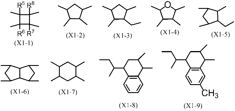
- X 3 is a tetravalent organic group derived from the tetracarboxylic acid derivatives. Specifically, at least one selected from the group consisting of structures represented by the following formulas (X1-1) to (X1-45) is preferable.
- R 5 , R 6 , R 7 and R 8 are each independently a hydrogen atom, a halogen atom, an alkyl group having 1 to 6 carbon atoms, an alkenyl group having 2 to 6 carbon atoms, An alkynyl group or a phenyl group. From the viewpoint of liquid crystal alignment, R 5 , R 6 , R 7 , and R 8 are preferably a hydrogen atom, a halogen atom, a methyl group, or an ethyl group, and more preferably a hydrogen atom or a methyl group.
- X 3 is preferably (X1-10), (X1-11), or (X1-29) from the viewpoint of liquid crystal alignment and reliability, and (X1-10) or (X1-11) ) Is more preferable.
- Y 3 is a divalent organic group derived from a diamine containing the structure of Formula (2).
- R 4 is a single bond or a benzene ring.
- a divalent organic group derived from a certain diamine is preferred.
- R 13 is a hydrogen atom or an alkyl group having 1 to 5 carbon atoms, and a hydrogen atom or a methyl group is particularly preferable from the viewpoint of ease of imidization by heating.
- the specific polymer (B) in the present invention has a ratio of at least one structural unit selected from the structural unit represented by the above formula (5) and the structural unit imidized from the structural unit. It is preferably contained in an amount of 20 to 100 mol%, more preferably 30 to 70 mol%, more preferably 50 to 70 mol%, from the viewpoint of achieving both liquid crystal orientation and reliability. Is more preferable.
- the specific polymer (B) in the present invention is further a structural unit represented by the following formula (6) and / or a structural unit obtained by imidizing it. You may have.
- R ⁇ 14 > is the same as the definition of R ⁇ 13 > of said Formula (5).
- X 4 is a tetravalent organic group derived from a tetracarboxylic acid derivative, and its structure is not particularly limited. Specific examples include the structures of the above formulas (X1-1) to (X-45).
- Y 4 is a divalent organic group derived from diamine, and its structure is not particularly limited. Specific examples of Y 4 include structures of the following formulas (Y-1) to (Y-138).
- the polyamic acid ester which is a polyimide precursor used in the present invention can be synthesized by the method (1), (2) or (3) shown below.
- the polyamic acid ester can be synthesized by esterifying a polyamic acid obtained from tetracarboxylic dianhydride and diamine. Specifically, the polyamic acid and the esterifying agent are reacted in the presence of an organic solvent at ⁇ 20 ° C. to 150 ° C., preferably 0 ° C. to 50 ° C., for 30 minutes to 24 hours, preferably 1 to 4 hours. Can be synthesized.
- the esterifying agent is preferably one that can be easily removed by purification, and N, N-dimethylformamide dimethyl acetal, N, N-dimethylformamide diethyl acetal, N, N-dimethylformamide dipropyl acetal, N, N-dimethylformamide Dineopentyl butyl acetal, N, N-dimethylformamide di-t-butyl acetal, 1-methyl-3-p-tolyltriazene, 1-ethyl-3-p-tolyltriazene, 1-propyl-3-p -Tolyltriazene, 4- (4,6-dimethoxy-1,3,5-triazin-2-yl) -4-methylmorpholinium chloride and the like.
- the addition amount of the esterifying agent is preferably 2 to 6 molar equivalents per 1 mol of the polyamic acid repeating unit.
- the solvent used in the above reaction is preferably N, N-dimethylformamide, N-methyl-2-pyrrolidone, or ⁇ -butyrolactone in view of polymer solubility. These may be used alone or in combination of two or more. Good.
- the concentration at the time of synthesis is preferably 1 to 30% by mass, and more preferably 5 to 20% by mass from the viewpoint that polymer precipitation is unlikely to occur and a high molecular weight product is easily obtained.
- Polyamic acid ester can be synthesized from tetracarboxylic acid diester dichloride and diamine. Specifically, tetracarboxylic acid diester dichloride and diamine in the presence of a base and an organic solvent at ⁇ 20 ° C. to 150 ° C., preferably 0 ° C. to 50 ° C., for 30 minutes to 24 hours, preferably 1 to 4 hours. It can be synthesized by reacting.
- a base pyridine, triethylamine, 4-dimethylaminopyridine and the like can be used, but pyridine is preferable because the reaction proceeds gently.
- the addition amount of the base is preferably 2 to 4 times the molar amount of the tetracarboxylic acid diester dichloride from the viewpoint of easy removal and high molecular weight.
- the solvent used in the above reaction is preferably N-methyl-2-pyrrolidone or ⁇ -butyrolactone in view of the solubility of the monomer and polymer, and these may be used alone or in combination.
- the polymer concentration at the time of synthesis is preferably 1 to 30% by mass, and more preferably 5 to 20% by mass from the viewpoint that polymer precipitation is difficult to occur and a high molecular weight product is easily obtained.
- the solvent used for the synthesis of the polyamic acid ester is preferably dehydrated as much as possible, and it is preferable to prevent mixing of outside air in a nitrogen atmosphere.
- Polyamic acid ester can be synthesized by polycondensation of tetracarboxylic acid diester and diamine. Specifically, tetracarboxylic acid diester and diamine in the presence of a condensing agent, a base, and an organic solvent at 0 ° C. to 150 ° C., preferably 0 ° C. to 100 ° C., for 30 minutes to 24 hours, preferably 3 to 15 It can synthesize
- condensing agent examples include triphenyl phosphite, dicyclohexylcarbodiimide, 1-ethyl-3- (3-dimethylaminopropyl) carbodiimide hydrochloride, N, N′-carbonyldiimidazole, dimethoxy-1,3,5-triazide.
- Nylmethylmorpholinium O- (benzotriazol-1-yl) -N, N, N ′, N′-tetramethyluronium tetrafluoroborate, O- (benzotriazol-1-yl) -N, N , N ′, N′-tetramethyluronium hexafluorophosphate, (2,3-dihydro-2-thioxo-3-benzoxazolyl) phosphonate diphenyl, and the like.
- the addition amount of the condensing agent is preferably 2 to 3 times the molar amount of the tetracarboxylic acid diester.
- tertiary amines such as pyridine and triethylamine can be used.
- the addition amount of the base is preferably 2 to 4 times mol with respect to the diamine component from the viewpoint of easy removal and high molecular weight.
- the reaction proceeds efficiently by adding Lewis acid as an additive.
- Lewis acid lithium halides such as lithium chloride and lithium bromide are preferable.
- the addition amount of the Lewis acid is preferably 0 to 1.0 times mol with respect to the diamine component.
- the synthesis method (1) or (2) is particularly preferable.
- the polyamic acid ester solution obtained as described above can be polymerized by pouring into a poor solvent while stirring well. Precipitation is performed several times, and after washing with a poor solvent, a purified polyamic acid ester powder can be obtained at room temperature or by heating and drying.
- a poor solvent is not specifically limited, Water, methanol, ethanol, hexane, butyl cellosolve, acetone, toluene etc. are mentioned.
- the organic solvent used in the above reaction is not particularly limited as long as the produced polyamic acid can be dissolved, but specific examples thereof include N, N-dimethylformamide, N, N-dimethylacetamide, Examples thereof include N-methyl-2-pyrrolidone, N-methylcaprolactam, dimethyl sulfoxide, tetramethyl urea, pyridine, dimethyl sulfone, hexamethyl sulfoxide, and ⁇ -butyrolactone. These may be used alone or in combination. Furthermore, even if the solvent does not dissolve the polyamic acid, it may be used by mixing with the above solvent as long as the produced polyamic acid does not precipitate. In addition, since water in the organic solvent inhibits the polymerization reaction and further causes hydrolysis of the generated polyamic acid, it is preferable to use a dehydrated and dried organic solvent as much as possible.
- a method of mixing a tetracarboxylic dianhydride component and a diamine component in an organic solvent a solution in which the diamine component is dispersed or dissolved in an organic solvent is stirred, and the tetracarboxylic dianhydride component is left as it is or organically.
- a method of adding by dispersing or dissolving in a solvent a method of adding a diamine component to a solution in which a tetracarboxylic dianhydride component is dispersed or dissolved in an organic solvent, and a tetracarboxylic dianhydride component and a diamine component.
- the method of adding alternately etc. are mentioned, In this invention, any of these methods may be sufficient.
- a tetracarboxylic dianhydride component or a diamine component consists of multiple types of compounds, these multiple types of components may be reacted in advance or may be reacted individually and sequentially.
- the temperature at which the tetracarboxylic dianhydride component and the diamine component are reacted in an organic solvent is usually 0 to 150 ° C., preferably 5 to 100 ° C., more preferably 10 to 80 ° C. When the temperature is higher, the polymerization reaction is completed earlier, but when it is too high, a high molecular weight polymer may not be obtained.
- the reaction can be carried out at any concentration, but if the concentration is too low, it is difficult to obtain a high molecular weight polymer, and if the concentration is too high, the viscosity of the reaction solution becomes too high and uniform stirring is difficult. Therefore, the content is preferably 1 to 50% by mass, more preferably 5 to 30% by mass.
- the initial reaction may be carried out at a high concentration, and then an organic solvent may be added.
- the ratio of the tetracarboxylic dianhydride component and the diamine component used for the polyamic acid polymerization reaction is preferably 1: 0.8 to 1.2 in terms of molar ratio.
- the polyamic acid obtained by using an excess of the diamine component may increase the coloration of the solution, it may be 1: 0.8 to 1 if the coloration of the solution is a concern. Similar to the normal polycondensation reaction, the closer the molar ratio is to 1: 1, the higher the molecular weight of the polyamic acid obtained. If the molecular weight of the polyamic acid is too small, the strength of the coating film obtained therefrom may be insufficient.
- the polyamic acid used in the liquid crystal aligning agent of the present invention has a reduced viscosity (concentration of 0.5 dl / g, 30 ° C. in NMP) of preferably 0.1 to 2.0, more preferably 0.2 to 1.5. .
- the precipitate is collected and purified.
- the polyamic acid solution is preferably added to a stirring poor solvent, and the precipitate is recovered.
- a poor solvent used for precipitation collection recovery of polyamic acid, Methanol, acetone, hexane, butyl cellosolve, heptane, methyl ethyl ketone, methyl isobutyl ketone, ethanol, toluene, benzene etc. can be illustrated.
- the polyamic acid precipitated by introducing it into a poor solvent can be recovered by filtration, washing and drying at room temperature or under reduced pressure at normal temperature or under reduced pressure.
- the polyamic acid can be purified.
- the polyimide in the specific polymer (A) and the specific polymer (B) can be produced by imidizing the polyamic acid ester or polyamic acid which is a polyimide precursor.
- a polyimide is produced from a polyamic acid ester
- chemical imidization in which a basic catalyst is added to a polyamic acid solution obtained by dissolving the polyamic acid ester solution or the polyamic acid ester resin powder in an organic solvent is simple.
- Chemical imidization is preferable because the imidization reaction proceeds at a relatively low temperature and the molecular weight of the polymer does not easily decrease during the imidization process.
- Chemical imidation can be performed by stirring a polymer to be imidized in an organic solvent in the presence of a basic catalyst and an acid anhydride.
- a basic catalyst include pyridine, triethylamine, trimethylamine, tributylamine, trioctylamine and the like. Of these, pyridine is preferable because it has an appropriate basicity for proceeding with the reaction.
- the acid anhydride include acetic anhydride, trimellitic anhydride, pyromellitic anhydride and the like. Among them, use of acetic anhydride is preferable because purification after completion of the reaction is facilitated.
- the temperature for carrying out the imidization reaction is ⁇ 20 ° C. to 140 ° C., preferably 0 ° C. to 100 ° C., and the reaction time can be 1 to 100 hours.
- the amount of the basic catalyst is 0.5 to 30 mol times, preferably 2 to 20 mol times the amic acid group, and the amount of the acid anhydride is 1 to 50 mol times, preferably 3 to 30 mol times the amic acid group. Is double.
- the imidation ratio of the resulting polymer can be controlled by adjusting the amount of catalyst, temperature, and reaction time.
- the liquid crystal aligning agent of the present invention is preferable.
- the polyimide solution obtained as described above can be polymerized by pouring into a poor solvent while stirring well. Precipitation is performed several times, and after washing with a poor solvent, a purified polyamic acid ester powder can be obtained at room temperature or by heating and drying.
- the poor solvent is not particularly limited, and examples thereof include methanol, acetone, hexane, butyl cellosolve, heptane, methyl ethyl ketone, methyl isobutyl ketone, ethanol, toluene, and benzene.
- the liquid crystal aligning agent of this invention contains the said specific polymer (A) and the said specific polymer (B).
- Each of the specific polymer (A) and the specific polymer (B) contained in the liquid crystal aligning agent of the present invention may be one type or two or more types.
- other polymers that is, a divalent group represented by the formula (1) and a divalent group represented by the formula (2) You may contain the polymer which does not have.
- Such other polymers include polyamic acid, polyimide, polyamic acid ester, polyester, polyamide, polyurea, polyorganosiloxane, cellulose derivative, polyacetal, polystyrene or derivatives thereof, poly (styrene-phenylmaleimide) derivative, poly (meth) An acrylate etc. can be mentioned.
- the liquid crystal aligning agent of the present invention contains other polymers, the total content of the specific polymer (A) and the specific polymer (B) in the total polymer components is preferably 5% by mass or more, One example is 5 to 95% by mass.
- the liquid crystal aligning agent preferably takes the form of a coating solution, and is preferably a coating solution containing a polymer component and an organic solvent for dissolving the polymer component.
- content (concentration) of the polymer in a liquid crystal aligning agent can be suitably changed with the setting of the thickness of the coating film to form. 1% by mass or more is preferable from the viewpoint of forming a uniform and defect-free coating film, and 10% by mass or less is preferable from the viewpoint of storage stability of the solution.
- a particularly preferable polymer content is 2 to 8% by mass.
- the organic solvent contained in the liquid crystal aligning agent is not particularly limited as long as the polymer component is uniformly dissolved.
- Specific examples are N, N-dimethylformamide, N, N-dimethylacetamide, N-methyl-2-pyrrolidone, N-ethyl-2-pyrrolidone, dimethyl sulfoxide, ⁇ -butyrolactone, 1,3-dimethyl.
- -2-Imidazolidinone, methyl ethyl ketone, cyclohexanone, cyclopentanone and the like can be mentioned.
- N-methyl-2-pyrrolidone, N-ethyl-2-pyrrolidone, or ⁇ -butyrolactone is preferably used.
- the organic solvent contained in the liquid crystal aligning agent may be a mixed solvent that is used in combination with a solvent that improves the coatability and the surface smoothness of the coating film when applying the liquid crystal aligning agent in addition to the above-mentioned solvent.
- a mixed solvent is preferably used also in the liquid crystal aligning agent of the present invention. Specific examples of the organic solvent to be used in combination are given below, but the organic solvent is not limited to these examples.
- ethanol isopropyl alcohol, 1-butanol, 2-butanol, isobutyl alcohol, tert-butyl alcohol, 1-pentanol, 2-pentanol, 3-pentanol, 2-methyl-1-butanol, isopentyl alcohol, tert-pentyl alcohol, 3-methyl-2-butanol, neopentyl alcohol, 1-hexanol, 2-methyl-1-pentanol, 2-methyl-2-pentanol, 2-ethyl-1-butanol, 1-heptanol 2-heptanol, 3-heptanol, 1-octanol, 2-octanol, 2-ethyl-1-hexanol, cyclohexanol, 1-methylcyclohexanol, 2-methylcyclohexanol, 3-methylcyclohexanol, 2,6- Dimethyl 4-heptanol, 1,2-ethanediol,
- D 1 represents an alkyl group having 1 to 3 carbon atoms
- D 2 represents an alkyl group having 1 to 3 carbon atoms
- D-3 represents an alkyl group having 1 to 4 carbon atoms.
- preferred solvent combinations include N-methyl-2-pyrrolidone, ⁇ -butyrolactone, ethylene glycol monobutyl ether, N-methyl-2-pyrrolidone, ⁇ -butyrolactone, propylene glycol monobutyl ether, N-ethyl-2- Pyrrolidone and propylene glycol monobutyl ether, N-methyl-2-pyrrolidone and ⁇ -butyrolactone, 4-hydroxy-4-methyl-2-pentanone and diethylene glycol diethyl ether, N-methyl-2-pyrrolidone, ⁇ -butyrolactone and propylene glycol mono Butyl ether, 2,6-dimethyl-4-heptanone, N-methyl-2-pyrrolidone, ⁇ -butyrolactone, propylene glycol monobutyl ether, diisopropyl ether, N-methyl-2-pi Examples thereof include loridone, ⁇ -butyrolactone, propylene
- an additive such as a silane coupling agent may be added to the liquid crystal aligning agent of the present invention, and other resin components may be added.
- Examples of the compound that improves the adhesion between the liquid crystal alignment film and the substrate include a functional silane-containing compound and an epoxy group-containing compound, such as 3-aminopropyltrimethoxysilane, 3-aminopropyltriethoxysilane, 3- Glycidoxypropyltriethoxysilane, 3-glycidoxypropyltrimethoxysilane, 3-glycidoxypropylmethyldiethoxysilane, 2-aminopropyltrimethoxysilane, 2-aminopropyltriethoxysilane, N- (2- Aminoethyl) -3-aminopropyltrimethoxysilane, N- (2-aminoethyl) -3-aminopropylmethyldimethoxysilane, 3-ureidopropyltrimethoxysilane, 3-ureidopropyltriethoxysilane, N-ethoxycarbonyl- 3-aminopropyl
- additives may be added to the liquid crystal aligning agent of the present invention in order to increase the mechanical strength of the film.
- additives are preferably 0.1 to 30 parts by mass with respect to 100 parts by mass of the polymer component contained in the liquid crystal aligning agent. If the amount is less than 0.1 parts by mass, the effect cannot be expected. If the amount exceeds 30 parts by mass, the orientation of the liquid crystal is lowered.
- the liquid crystal alignment film of the present invention is obtained from the liquid crystal alignment agent. If an example of the method of obtaining a liquid crystal aligning film from a liquid crystal aligning agent is given, a liquid crystal aligning agent in the form of a coating solution is applied to a substrate, dried and baked on a film obtained by rubbing or photo-aligning. And a method of performing an alignment treatment.
- the substrate on which the liquid crystal aligning agent is applied is not particularly limited as long as it is a highly transparent substrate, and a plastic substrate such as an acrylic substrate or a polycarbonate substrate can be used together with a glass substrate or a silicon nitride substrate. At that time, it is preferable to use a substrate on which an ITO electrode or the like for driving the liquid crystal is used from the viewpoint of simplification of the process. Further, in the reflection type liquid crystal display element, an opaque material such as a silicon wafer can be used as long as only one substrate is used, and a material that reflects light such as aluminum can be used for the electrode in this case.
- the method for applying the liquid crystal aligning agent is not particularly limited, but industrially, screen printing, offset printing, flexographic printing, inkjet method, and the like are common. Other coating methods include a dipping method, a roll coater method, a slit coater method, a spinner method, and a spray method, and these may be used depending on the purpose.
- the solvent is evaporated and baked by a heating means such as a hot plate, a thermal circulation oven, an IR (infrared) oven, or the like.
- a heating means such as a hot plate, a thermal circulation oven, an IR (infrared) oven, or the like.
- Arbitrary temperature and time can be selected for the drying and baking steps after applying the liquid crystal aligning agent.
- the thickness of the liquid crystal alignment film after firing is not particularly limited, but if it is too thin, the reliability of the liquid crystal display element may be lowered, so that it is preferably 5 to 300 nm, more preferably 10 to 200 nm.
- the liquid crystal alignment film of the present invention is suitable as a liquid crystal alignment film of a horizontal electric field type liquid crystal display element such as an IPS mode or an FFS mode, and is particularly useful as a liquid crystal alignment film of an FFS mode liquid crystal display element.
- the liquid crystal display device of the present invention is a device in which a liquid crystal cell is prepared by a known method after obtaining a substrate with a liquid crystal alignment film obtained from the liquid crystal aligning agent, and the liquid crystal cell is used as an element.
- a liquid crystal display element having a passive matrix structure will be described as an example.
- an active matrix liquid crystal display element in which a switching element such as a TFT (Thin Film Transistor) is provided in each pixel portion constituting the image display may be used.
- a transparent glass substrate is prepared, a common electrode is provided on one substrate, and a segment electrode is provided on the other substrate.
- These electrodes can be ITO electrodes, for example, and are patterned so as to display a desired image.
- an insulating film is provided on each substrate so as to cover the common electrode and the segment electrode.
- the insulating film can be, for example, a film made of SiO 2 —TiO 2 formed by a sol-gel method.
- a liquid crystal alignment film is formed on each substrate under the above conditions.
- an ultraviolet curable sealing material is disposed at a predetermined position on one of the two substrates on which the liquid crystal alignment film is formed, and liquid crystals are disposed at predetermined positions on the liquid crystal alignment film surface.
- the other substrate is bonded and pressure-bonded so that the liquid crystal alignment film faces, and the liquid crystal is spread on the front surface of the liquid crystal alignment film, and then the entire surface of the substrate is irradiated with ultraviolet rays to cure the sealing material. Get a cell.
- an opening that can be filled with liquid crystal from the outside is provided when the sealing material is disposed at a predetermined location on one substrate, and the liquid crystal is After the substrates are bonded without being arranged, a liquid crystal material is injected into the liquid crystal cell through an opening provided in the sealing material, and then the opening is sealed with an adhesive to obtain a liquid crystal cell.
- the liquid crystal material may be injected by a vacuum injection method or a method utilizing capillary action in the atmosphere.
- liquid crystal material examples include a nematic liquid crystal and a smectic liquid crystal.
- a nematic liquid crystal is preferable, and either a positive liquid crystal material or a negative liquid crystal material may be used.
- a polarizing plate is installed. Specifically, it is preferable to attach a pair of polarizing plates to the surfaces of the two substrates opposite to the liquid crystal layer.
- the liquid crystal display element of the present invention is not limited to the above description as long as the liquid crystal aligning agent of the present invention is used, and may be produced by other known methods. The process of obtaining a liquid crystal display element is disclosed in, for example, paragraph 0074 on page 17 to paragraph 0081 on page 19 of Japanese Unexamined Patent Publication No. 2015-135393.
- ⁇ Viscosity> The viscosity of the polymer solution was measured using an E-type viscometer TVE-22H (manufactured by Toki Sangyo Co., Ltd.) at a sample amount of 1.1 mL, cone rotor TE-1 (1 ° 34 ′, R24), and a temperature of 25 ° C. .
- the imidation ratio of polyimide was measured as follows. 30 mg of polyimide powder was added to an NMR (nuclear magnetic resonance) sample tube (NMR sampling tube standard, (5) (manufactured by Kusano Kagaku Co., Ltd.)) 05 mass% TMS (tetramethylsilane) mixture) (0.53 ml) was added and completely dissolved by applying ultrasonic waves. This solution was measured for proton NMR at 500 MHz with an NMR measuring instrument (JNW-ECA500) (manufactured by JEOL Datum).
- NMR nuclear magnetic resonance
- the imidation rate is determined based on protons derived from structures that do not change before and after imidation as reference protons, and the peak integrated value of these protons and proton peaks derived from NH groups of amic acid that appear in the vicinity of 9.5 ppm to 10.0 ppm. It calculated
- Imidization rate (%) (1 ⁇ ⁇ x / y) ⁇ 100
- x is the proton peak integrated value derived from the NH group of the amic acid
- y is the peak integrated value of the reference proton
- ⁇ is the N of the amic acid in the case of polyamic acid (imidation rate is 0%). It is the number ratio of the reference proton to one H group proton.
- Example 1 In a 50 mL Erlenmeyer flask containing a stir bar, 2.13 g of the polyimide solution (SPI-1) obtained in Synthesis Example 1 and 8.47 g of the polyamic acid solution (PAA-1) obtained in Synthesis Example 4 were weighed. The mixture was stirred with a magnetic stirrer for 2 hours to obtain a liquid crystal aligning agent (A-1).
- Example 2 In a 50 mL Erlenmeyer flask containing a stir bar, 2.00 g of the polyimide solution (SPI-2) obtained in Synthesis Example 2 and 8.11 g of the polyamic acid solution (PAA-1) obtained in Synthesis Example 4 were weighed. Then, the mixture was stirred with a magnetic stirrer for 2 hours to obtain a liquid crystal aligning agent (A-2).
- Example 3 In a 50 mL Erlenmeyer flask containing a stir bar, 2.03 g of the polyimide solution (SPI-3) obtained in Synthesis Example 3 and 8.04 g of the polyamic acid solution (PAA-1) obtained in Synthesis Example 4 were weighed. Then, the mixture was stirred with a magnetic stirrer for 2 hours to obtain a liquid crystal aligning agent (A-3).
- Example 4 In a 50 mL Erlenmeyer flask containing a stir bar, 5.43 g of the polyimide solution (SPI-1) obtained in Synthesis Example 1 and 5.41 g of the polyamic acid solution (PAA-1) obtained in Synthesis Example 4 were weighed. Then, the mixture was stirred with a magnetic stirrer for 2 hours to obtain a liquid crystal aligning agent (A-4).
- a method for manufacturing a liquid crystal cell for evaluating the stored charge relaxation characteristics, flicker characteristics, and liquid crystal alignment is described below.
- a liquid crystal cell having a configuration of an FFS liquid crystal display element is manufactured.
- a substrate with electrodes was prepared.
- the substrate is a glass substrate having a size of 30 mm ⁇ 35 mm and a thickness of 0.7 mm.
- an IZO electrode constituting the counter electrode as the first layer is formed on the entire surface.
- a SiN (silicon nitride) film formed by the CVD method is formed as the second layer.
- the second layer SiN film has a thickness of 500 nm and functions as an interlayer insulating film.
- a comb-like pixel electrode formed by patterning an IZO film is arranged as a third layer on the second layer SiN film to form two pixels, a first pixel and a second pixel. is doing.
- the size of each pixel is 10 mm long and about 5 mm wide.
- the first-layer counter electrode and the third-layer pixel electrode are electrically insulated by the action of the second-layer SiN film.
- the third-layer pixel electrode has a comb-like shape configured by arranging a plurality of U-shaped electrode elements having a bent central portion.
- the width in the short direction of each electrode element is 3 ⁇ m, and the distance between the electrode elements is 6 ⁇ m. Since the pixel electrode forming each pixel is configured by arranging a plurality of bent-shaped electrode elements having a bent central portion, the shape of each pixel is not a rectangular shape, and the central portion is similar to the electrode element. It has a shape that is bent in the shape of bold, similar to the “Kugi”.
- Each pixel is divided into upper and lower portions with a central bent portion as a boundary, and has a first region on the upper side of the bent portion and a second region on the lower side.
- the formation directions of the electrode elements of the pixel electrodes constituting them are different. That is, when the rubbing direction of the liquid crystal alignment film to be described later is used as a reference, in the first region of the pixel, the electrode element of the pixel electrode is formed to form an angle of + 10 ° (clockwise), and in the second region of the pixel The electrode elements of the pixel electrode are formed at an angle of ⁇ 10 ° (clockwise).
- the direction of the rotation operation (in-plane switching) of the liquid crystal induced by the voltage application between the pixel electrode and the counter electrode in the substrate plane is It is comprised so that it may become a mutually reverse direction.
- liquid crystal aligning agents obtained in Examples and Comparative Examples were filtered through a filter having a pore diameter of 1.0 ⁇ m, and then applied to the prepared substrate with electrodes by spin coating. After drying on an 80 ° C. hot plate for 2 minutes, baking was performed in a hot air circulation oven at 230 ° C. for 20 minutes to obtain a polyimide film having a thickness of 60 nm.
- This polyimide film is rubbed with a rayon cloth (roller diameter: 120 mm, roller rotation speed: 500 rpm, moving speed: 30 mm / sec, indentation length: 0.3 mm, rubbing direction: inclined by 10 ° with respect to the third layer IZO comb-teeth electrode Then, ultrasonic cleaning was performed for 1 minute in pure water for cleaning, and water droplets were removed by air blow. Then, it dried for 15 minutes at 80 degreeC, and obtained the board
- a substrate with a liquid crystal alignment film was obtained.
- One set of these two substrates with a liquid crystal alignment film is printed, and the sealant is printed on the substrate leaving the liquid crystal injection port.
- the other substrate has the liquid crystal alignment film surface facing and the rubbing direction is antiparallel. They were pasted together.
- the sealing agent was cured to produce an empty cell having a cell gap of 4 ⁇ m.
- Liquid crystal MLC-3019 manufactured by Merck & Co., Inc.
- was injected into this empty cell by a reduced pressure injection method was sealed to obtain an FFS liquid crystal cell.
- the obtained liquid crystal cell was heated at 120 ° C. for 1 hour and allowed to stand at 23 ° C. overnight, and then used for evaluation of liquid crystal alignment.
- the liquid crystal cell is placed between two polarizing plates arranged so that their polarization axes are orthogonal to each other, and the pixel electrode and the counter electrode are short-circuited to be at the same potential, and the LED is displayed from under the two polarizing plates.
- the angle of the liquid crystal cell was adjusted so that the brightness of the LED backlight transmitted light measured on the two polarizing plates was minimized by irradiating the backlight.
- the VT characteristics voltage-transmittance characteristics
- an AC voltage with a relative transmittance of 23% is measured. Calculated. Since this AC voltage corresponds to a region where the change in luminance with respect to the voltage is large, it is convenient to evaluate the accumulated charge via the luminance.
- a rectangular wave having a relative transmittance of 23% at a temperature of 23 ° C. and a frequency of 30 Hz was applied for 5 minutes, and then a +1.0 V DC voltage was superimposed and driven for 30 minutes. Thereafter, the DC voltage was turned off, and only a rectangular wave having an AC voltage with a relative transmittance of 23% and a frequency of 30 Hz was applied for 30 minutes.
- the liquid crystal cell is placed between two polarizing plates arranged so that their polarization axes are orthogonal to each other, and the pixel electrode and the counter electrode are short-circuited to be at the same potential, and the LED is displayed from under the two polarizing plates.
- the angle of the liquid crystal cell was adjusted so that the brightness of the LED backlight transmitted light measured on the two polarizing plates was minimized by irradiating the backlight.
- the VT characteristics voltage-transmittance characteristics
- an AC voltage with a relative transmittance of 23% is measured. Calculated. Since this AC voltage corresponds to a region where the change in luminance with respect to the voltage is large, it is convenient for evaluating the flicker characteristics.
- the flicker amplitude is a data acquisition / data logger switch unit 34970A (Agilent Technologies) that connects the transmitted light of the LED backlight that has passed through the two polarizing plates and the liquid crystal cell between them through a photodiode and an IV conversion amplifier. ).
- the flicker level was calculated by the following formula.
- Flicker level (%) ⁇ flicker amplitude / (2 ⁇ z) ⁇ ⁇ 100
- z is a value obtained by reading the luminance when driven by an AC voltage having a frequency of 30 Hz with a relative transmittance of 23% by the data collection / data logger switch unit 34970A.
- the flicker characteristics are evaluated as “good” when the flicker level is kept below 3% by 30 minutes after the start of lighting of the LED backlight and the application of the AC voltage, and the flicker level after 30 minutes. Was defined as “bad” and evaluated.
- the rotation angle when the liquid crystal cell was rotated from the angle at which the second region of the first pixel became darkest to the angle at which the first region became darkest was calculated as an angle ⁇ .
- the second area was compared with the first area, and a similar angle ⁇ was calculated.
- the average value of the angle ⁇ values of the first pixel and the second pixel was calculated as the angle ⁇ of the liquid crystal cell.
- Example 5 The liquid crystal aligning agent (A-1) obtained in Example 1 was filtered through a filter having a pore size of 1.0 ⁇ m, and then a liquid crystal cell was produced as described above.
- the time required for the relative transmittance to drop to 23% was 8 minutes, which was favorable.
- the flicker level was 1%, which was favorable.
- ⁇ was 0.21 ° and good.
- Example 6 Except that the liquid crystal aligning agent (A-2) obtained in Example 2 was used, the relaxation characteristics of the accumulated charges were evaluated in the same manner as in Example 5. As a result, the relative transmittance decreased to 23%. The time required was 4 minutes and was good. Next, as a result of evaluating the flicker characteristics by the same method as in Example 5, the flicker level was 1%, which was favorable. Moreover, as a result of evaluating liquid crystal orientation by the method similar to Example 5, (DELTA) was 0.06 degree and was favorable.
- Example 7 Except that the liquid crystal aligning agent (A-3) obtained in Example 3 was used, as a result of evaluating the relaxation characteristics of accumulated charges by the same method as in Example 5, it was found that the relative transmittance decreased to 23%. The time required was 4 minutes and was good. Next, as a result of evaluating the flicker characteristics by the same method as in Example 5, the flicker level was 1%, which was favorable. Moreover, as a result of evaluating liquid crystal orientation by the method similar to Example 5, (DELTA) was 0.05 degree and was favorable.
- Example 8 Except that the liquid crystal aligning agent (A-4) obtained in Example 4 was used, as a result of evaluating the relaxation characteristics of accumulated charges by the same method as in Example 5, it was found that the relative transmittance decreased to 23%. The time required was good, 26 minutes. Next, as a result of evaluating flicker characteristics by the same method as in Example 5, the flicker level was 0.3%, which was favorable. Moreover, as a result of evaluating liquid crystal orientation by the method similar to Example 5, (DELTA) was 0.22 degree
- Comparative Example 4 Except that the liquid crystal aligning agent (B-1) obtained in Comparative Example 1 was used, the relaxation characteristics of the accumulated charges were evaluated in the same manner as in Example 5. As a result, the relative transmittance decreased to 23%. The time required was good, 26 minutes. Next, as a result of evaluating the flicker characteristics by the same method as in Example 5, the flicker level was 2%, which was favorable. Moreover, as a result of evaluating liquid crystal orientation by the method similar to Example 5, (DELTA) was 0.63 degree
- Comparative Example 5 Except that the liquid crystal aligning agent (B-2) obtained in Comparative Example 2 was used, the relaxation characteristics of the accumulated charges were evaluated in the same manner as in Example 5. As a result, the relative transmittance decreased to 23%. The time required was good, 24 minutes. Next, as a result of evaluating the flicker characteristics by the same method as in Example 5, the flicker level was 6%, which was poor. Moreover, as a result of evaluating liquid crystal orientation by the method similar to Example 5, (DELTA) was 0.16 degree and was favorable.
- Comparative Example 6 Except that the liquid crystal aligning agent (B-3) obtained in Comparative Example 3 was used, the relaxation characteristics of the accumulated charges were evaluated in the same manner as in Example 5. As a result, the relative transmittance was 23 even after 30 minutes. % Did not fall and was bad. Next, as a result of evaluating the flicker characteristics in the same manner as in Example 5, the flicker level was 0.7%, which was favorable. Moreover, as a result of evaluating liquid crystal orientation by the method similar to Example 5, (DELTA) was 0.11 degree and was favorable.
- Table 1 shows the results of evaluation of relaxation characteristics of accumulated charges, flicker characteristics, and liquid crystal orientation when the liquid crystal aligning agents obtained in Examples and Comparative Examples are used.
- the liquid crystal aligning agent of the present invention is widely used for a liquid crystal display element of a vertical electric field method such as a TN method or a VA method, particularly a horizontal electric field method such as an IPS method or an FFS method. It should be noted that the entire contents of the specification, claims, drawings, and abstract of Japanese Patent Application No. 2016-158014 filed on August 10, 2016 are cited herein as disclosure of the specification of the present invention. Incorporate.
Landscapes
- Physics & Mathematics (AREA)
- Chemical & Material Sciences (AREA)
- Nonlinear Science (AREA)
- General Physics & Mathematics (AREA)
- Crystallography & Structural Chemistry (AREA)
- Mathematical Physics (AREA)
- Spectroscopy & Molecular Physics (AREA)
- Optics & Photonics (AREA)
- Health & Medical Sciences (AREA)
- Chemical Kinetics & Catalysis (AREA)
- Medicinal Chemistry (AREA)
- Polymers & Plastics (AREA)
- Organic Chemistry (AREA)
- Liquid Crystal (AREA)
- Macromolecular Compounds Obtained By Forming Nitrogen-Containing Linkages In General (AREA)
Abstract
Description
1.下記式(1)で表される構造を有する重合体(A)と、下記式(2)の構造を有する重合体(B)とを含むことを特徴とする液晶配向剤。


1. The liquid crystal aligning agent characterized by including the polymer (A) which has a structure represented by following formula (1), and the polymer (B) which has a structure of following formula (2).
3.前記重合体(B)が、前記式(2)で表される構造を有するジアミンとテトラカルボン酸二無水物との重縮合物であるポリイミド前駆体(B)及びそのイミド化物であるポリイミド(B)からなる群から選ばれる少なくとも1種の重合体である前記1に記載の液晶配向剤。 2. The polymer (A) is a polyimide precursor (A) which is a polycondensate of a diamine having a structure represented by the formula (1) and a tetracarboxylic dianhydride and a polyimide (A) which is an imidized product thereof. 2. The liquid crystal aligning agent according to 1 above, which is at least one polymer selected from the group consisting of:
3. The polymer (B) is a polyimide precursor (B) which is a polycondensate of a diamine having a structure represented by the formula (2) and a tetracarboxylic dianhydride, and a polyimide (B) 2. The liquid crystal aligning agent according to 1 above, which is at least one polymer selected from the group consisting of:

5.前記式(3)において、Y1が下記のいずれかの式で表される前記4に記載の液晶配向剤。


5). 5. The liquid crystal aligning agent according to 4, wherein Y 1 is represented by any one of the following formulas in the formula (3).

但し、式(5)中、X3はテトラカルボン酸誘導体に由来する4価の有機基であり、Y3は式(2)の構造を含むジアミンに由来する2価の有機基であり、R13は水素原子又は炭素数1~5のアルキル基である。
8.前記重合体(A)と前記重合体(B)の合計量に対して、前記重合体(A)の含有量が、10~95質量%であり、前記重合体(B)の含有量が、5~90質量%である前記1~7のいずれか1項に記載の液晶配向剤。
9.前記重合体(A)及び前記重合体(B)を溶解する有機溶媒を含有する前記1~8のいずれか1項に記載の液晶配向剤。
10.前記1~9のいずれか1項に記載の液晶配向剤から得られる液晶配向膜。
11.前記10に記載の液晶配向膜を具備する液晶表示素子。
12.液晶表示素子が横電界駆動方式である前記11に記載の液晶表示素子。
13.液晶表示素子がFFS方式である前記11又は12に記載の液晶表示素子。 7). 7. The liquid crystal aligning agent according to 1 to 6, wherein the polyimide precursor (B) has a structural unit represented by the following formula (5).
However, in formula (5), X 3 is a tetravalent organic group derived from a tetracarboxylic acid derivative, Y 3 is a divalent organic group derived from a diamine containing the structure of formula (2), and R 3 13 is a hydrogen atom or an alkyl group having 1 to 5 carbon atoms.
8). The content of the polymer (A) is 10 to 95% by mass with respect to the total amount of the polymer (A) and the polymer (B), and the content of the polymer (B) is 8. The liquid crystal aligning agent according to any one of 1 to 7, which is 5 to 90% by mass.
9. 9. The liquid crystal aligning agent according to any one of 1 to 8, comprising an organic solvent that dissolves the polymer (A) and the polymer (B).
10. 10. A liquid crystal alignment film obtained from the liquid crystal aligning agent according to any one of 1 to 9 above.
11. 11. A liquid crystal display device comprising the liquid crystal alignment film as described in 10 above.
12 12. The liquid crystal display element as described in 11 above, wherein the liquid crystal display element is of a horizontal electric field drive system.
13. 13. The liquid crystal display element as described in 11 or 12 above, wherein the liquid crystal display element is an FFS method.
特定重合体(A)の含有量は、特定重合体(A)と特定重合体(B)の合計量に対して、特定重合体(A)が10~95質量%であり、より好ましくは60~90重量%である。また、特定重合体(B)の含有量は、特定重合体(A)と特定重合体(B)の合計量に対して、90~5質量%であり、より好ましくは40~10質量%である。特定重合体(A)が少なすぎると、液晶配向膜の電荷蓄積特性やラビング耐性が悪化し、特定重合体(B)が少なすぎると、液晶の配向性や配向規制力が悪化する。本発明の液晶配向剤に含有される特定重合体(A)と特定重合体(B)は、それぞれ、1種類でも、2種類以上であってもよい。 The liquid crystal aligning agent of this invention contains the specific polymer (A) which has a structure represented by the said Formula (1), and the specific polymer (B) which has a structure of the said Formula (2), It is characterized by the above-mentioned. And
The content of the specific polymer (A) is 10 to 95% by mass of the specific polymer (A) with respect to the total amount of the specific polymer (A) and the specific polymer (B), more preferably 60%. ~ 90% by weight. The content of the specific polymer (B) is 90 to 5% by mass, more preferably 40 to 10% by mass, based on the total amount of the specific polymer (A) and the specific polymer (B). is there. When there are too few specific polymers (A), the charge storage characteristic and rubbing tolerance of a liquid crystal aligning film will deteriorate, and when there are too few specific polymers (B), the orientation and alignment control power of liquid crystals will deteriorate. Each of the specific polymer (A) and the specific polymer (B) contained in the liquid crystal aligning agent of the present invention may be one type or two or more types.
特定重合体(A)は上記式(1)で表される構造を有する重合体である。
式(1)中のR1は、得られる重合体の溶解性の観点から、炭素原子数1~3のアルキル基が好ましく、液晶配向性を損なわない点からメチル基が好ましい。 <Specific polymer (A)>
The specific polymer (A) is a polymer having a structure represented by the above formula (1).
R 1 in formula (1) is preferably an alkyl group having 1 to 3 carbon atoms from the viewpoint of the solubility of the resulting polymer, and is preferably a methyl group from the viewpoint of not impairing the liquid crystal orientation.

以下に、好ましいX1の構造である(A-1)~(A-21)を示すが、本発明はこれらに限定されるものではない。

The preferred X 1 structures (A-1) to (A-21) are shown below, but the present invention is not limited thereto.

特定重合体(A)は、式(3)で表される構造単位に加えて、さらに、下記式(4)で表される構造単位、及び/又はそれをイミド化した構造単位を有していてもよい。 The specific polymer (A) in the present invention contains at least one structural unit selected from the structural unit represented by the above formula (3) and the structural unit imidized from the structural unit of the specific polymer (A). The content is preferably 5 to 100 mol%, more preferably 10 to 100 mol%, and more preferably 20 to 100 mol% from the viewpoint of achieving both liquid crystal orientation and relaxation characteristics of accumulated charge. Is more preferable.
The specific polymer (A) has a structural unit represented by the following formula (4) and / or a structural unit obtained by imidizing the structural unit in addition to the structural unit represented by the formula (3). May be.


本発明における特定重合体(A)を構成するポリイミド前駆体の分子量は、重量平均分子量で2,000~500,000が好ましく、より好ましくは5,000~300,000であり、さらに好ましくは、10,000~100,000である。 When the specific polymer (A) has a structural unit represented by Formula (3) and a structural unit represented by Formula (4), the structural unit represented by Formula (3) is represented by Formula (3). ) And the formula (4) are preferably 10 mol% or more, more preferably 20 mol% or more, and particularly preferably 30 mol% or more.
The molecular weight of the polyimide precursor constituting the specific polymer (A) in the present invention is preferably 2,000 to 500,000, more preferably 5,000 to 300,000, and still more preferably, in terms of weight average molecular weight. 10,000 to 100,000.
ポリイミド前駆体をイミド化させる方法としては、ポリイミド前駆体の溶液をそのまま加熱する熱イミド化、又はポリイミド前駆体の溶液に触媒を添加する触媒イミド化が挙げられる。 The polyimide constituting the specific polymer (A) is obtained by ring-closing a polyimide precursor having a structural unit represented by the formula (3) and, if necessary, a structural unit represented by the formula (4). In this polyimide, the ring closure rate (also referred to as imidation rate) of the amic acid group is not necessarily 100%, and can be arbitrarily adjusted according to the use and purpose.
Examples of the method for imidizing the polyimide precursor include thermal imidization in which the polyimide precursor solution is heated as it is, or catalytic imidization in which a catalyst is added to the polyimide precursor solution.
本発明の液晶配向剤に含有される特定重合体(B)は、下記式(2)の構造を有する重合体である。

The specific polymer (B) contained in the liquid crystal aligning agent of this invention is a polymer which has a structure of following formula (2).


本発明に用いられるポリイミド前駆体であるポリアミック酸エステルは、以下に示す(1)、(2)又は(3)の方法で合成することができる。
(1)ポリアミック酸から合成する場合
ポリアミック酸エステルは、テトラカルボン酸二無水物とジアミンから得られるポリアミック酸をエステル化することによって合成することができる。
具体的には、ポリアミック酸とエステル化剤を有機溶剤の存在下で-20℃~150℃、好ましくは0℃~50℃において、30分~24時間、好ましくは1~4時間反応させることによって合成することができる。
エステル化剤としては、精製によって容易に除去できるものが好ましく、N,N-ジメチルホルムアミドジメチルアセタール、N,N-ジメチルホルムアミドジエチルアセタール、N,N-ジメチルホルムアミドジプロピルアセタール、N,N-ジメチルホルムアミドジネオペンチルブチルアセタール、N,N-ジメチルホルムアミドジ-t-ブチルアセタール、1-メチル-3-p-トリルトリアゼン、1-エチル-3-p-トリルトリアゼン、1-プロピル-3-p-トリルトリアゼン、4-(4,6-ジメトキシ-1,3,5-トリアジンー2-イル)-4-メチルモルホリニウムクロリドなどが挙げられる。エステル化剤の添加量は、ポリアミック酸の繰り返し単位1モルに対して、2~6モル当量が好ましい。
上記の反応に用いる溶媒は、ポリマーの溶解性からN,N-ジメチルホルムアミド、N-メチル-2-ピロリドン、又はγ-ブチロラクトンが好ましく、これらは1種又は2種以上を混合して用いてもよい。合成時の濃度は、ポリマーの析出が起こりにくく、かつ高分子量体が得やすいという観点から、1~30質量%が好ましく、5~20質量%がより好ましい。 <Method for producing polyamic acid ester>
The polyamic acid ester which is a polyimide precursor used in the present invention can be synthesized by the method (1), (2) or (3) shown below.
(1) When synthesizing from polyamic acid The polyamic acid ester can be synthesized by esterifying a polyamic acid obtained from tetracarboxylic dianhydride and diamine.
Specifically, the polyamic acid and the esterifying agent are reacted in the presence of an organic solvent at −20 ° C. to 150 ° C., preferably 0 ° C. to 50 ° C., for 30 minutes to 24 hours, preferably 1 to 4 hours. Can be synthesized.
The esterifying agent is preferably one that can be easily removed by purification, and N, N-dimethylformamide dimethyl acetal, N, N-dimethylformamide diethyl acetal, N, N-dimethylformamide dipropyl acetal, N, N-dimethylformamide Dineopentyl butyl acetal, N, N-dimethylformamide di-t-butyl acetal, 1-methyl-3-p-tolyltriazene, 1-ethyl-3-p-tolyltriazene, 1-propyl-3-p -Tolyltriazene, 4- (4,6-dimethoxy-1,3,5-triazin-2-yl) -4-methylmorpholinium chloride and the like. The addition amount of the esterifying agent is preferably 2 to 6 molar equivalents per 1 mol of the polyamic acid repeating unit.
The solvent used in the above reaction is preferably N, N-dimethylformamide, N-methyl-2-pyrrolidone, or γ-butyrolactone in view of polymer solubility. These may be used alone or in combination of two or more. Good. The concentration at the time of synthesis is preferably 1 to 30% by mass, and more preferably 5 to 20% by mass from the viewpoint that polymer precipitation is unlikely to occur and a high molecular weight product is easily obtained.
ポリアミック酸エステルは、テトラカルボン酸ジエステルジクロリドとジアミンから合成することができる。
具体的には、テトラカルボン酸ジエステルジクロリドとジアミンとを塩基と有機溶剤の存在下で-20℃~150℃、好ましくは0℃~50℃において、30分~24時間、好ましくは1~4時間反応させることによって合成することができる。
前記塩基には、ピリジン、トリエチルアミン、4-ジメチルアミノピリジンなどが使用できるが、反応が穏和に進行するためにピリジンが好ましい。塩基の添加量は、除去が容易な量で、かつ高分子量体が得やすいという観点から、テトラカルボン酸ジエステルジクロリドに対して、2~4倍モルであることが好ましい。
上記の反応に用いる溶媒は、モノマー及びポリマーの溶解性からN-メチル-2-ピロリドン、又はγ-ブチロラクトンが好ましく、これらは1種又は2種以上を混合して用いてもよい。合成時のポリマー濃度は、ポリマーの析出が起こりにくく、かつ高分子量体が得やすいという観点から、1~30質量%が好ましく、5~20質量%がより好ましい。また、テトラカルボン酸ジエステルジクロリドの加水分解を防ぐため、ポリアミック酸エステルの合成に用いる溶媒はできるだけ脱水されていることが好ましく、窒素雰囲気中で、外気の混入を防ぐのが好ましい。 (2) When synthesized by reaction of tetracarboxylic acid diester dichloride and diamine Polyamic acid ester can be synthesized from tetracarboxylic acid diester dichloride and diamine.
Specifically, tetracarboxylic acid diester dichloride and diamine in the presence of a base and an organic solvent at −20 ° C. to 150 ° C., preferably 0 ° C. to 50 ° C., for 30 minutes to 24 hours, preferably 1 to 4 hours. It can be synthesized by reacting.
As the base, pyridine, triethylamine, 4-dimethylaminopyridine and the like can be used, but pyridine is preferable because the reaction proceeds gently. The addition amount of the base is preferably 2 to 4 times the molar amount of the tetracarboxylic acid diester dichloride from the viewpoint of easy removal and high molecular weight.
The solvent used in the above reaction is preferably N-methyl-2-pyrrolidone or γ-butyrolactone in view of the solubility of the monomer and polymer, and these may be used alone or in combination. The polymer concentration at the time of synthesis is preferably 1 to 30% by mass, and more preferably 5 to 20% by mass from the viewpoint that polymer precipitation is difficult to occur and a high molecular weight product is easily obtained. In order to prevent hydrolysis of the tetracarboxylic acid diester dichloride, the solvent used for the synthesis of the polyamic acid ester is preferably dehydrated as much as possible, and it is preferable to prevent mixing of outside air in a nitrogen atmosphere.
ポリアミック酸エステルは、テトラカルボン酸ジエステルとジアミンを重縮合することにより合成することができる。
具体的には、テトラカルボン酸ジエステルとジアミンを縮合剤、塩基、及び有機溶剤の存在下で0℃~150℃、好ましくは0℃~100℃において、30分~24時間、好ましくは3~15時間反応させることによって合成することができる。
前記縮合剤には、トリフェニルホスファイト、ジシクロヘキシルカルボジイミド、1-エチル-3-(3-ジメチルアミノプロピル)カルボジイミド塩酸塩、N,N’-カルボニルジイミダゾール、ジメトキシ-1,3,5-トリアジニルメチルモルホリニウム、O-(ベンゾトリアゾール-1-イル)-N,N,N’,N’-テトラメチルウロニウム テトラフルオロボラート、O-(ベンゾトリアゾール-1-イル)-N,N,N’,N’-テトラメチルウロニウムヘキサフルオロホスファート、(2,3-ジヒドロ-2-チオキソ-3-ベンゾオキサゾリル)ホスホン酸ジフェニルなどが使用できる。縮合剤の添加量は、テトラカルボン酸ジエステルに対して2~3倍モルが好ましい。
前記塩基には、ピリジン、トリエチルアミンなどの3級アミンが使用できる。塩基の添加量は、除去が容易な量で、かつ高分子量体が得やすいという観点から、ジアミン成分に対して2~4倍モルが好ましい。
また、上記反応において、ルイス酸を添加剤として加えることで反応が効率的に進行する。ルイス酸としては、塩化リチウム、臭化リチウムなどのハロゲン化リチウムが好ましい。ルイス酸の添加量はジアミン成分に対して0~1.0倍モルが好ましい。 (3) When synthesizing from tetracarboxylic acid diester and diamine Polyamic acid ester can be synthesized by polycondensation of tetracarboxylic acid diester and diamine.
Specifically, tetracarboxylic acid diester and diamine in the presence of a condensing agent, a base, and an organic solvent at 0 ° C. to 150 ° C., preferably 0 ° C. to 100 ° C., for 30 minutes to 24 hours, preferably 3 to 15 It can synthesize | combine by making it react for time.
Examples of the condensing agent include triphenyl phosphite, dicyclohexylcarbodiimide, 1-ethyl-3- (3-dimethylaminopropyl) carbodiimide hydrochloride, N, N′-carbonyldiimidazole, dimethoxy-1,3,5-triazide. Nylmethylmorpholinium, O- (benzotriazol-1-yl) -N, N, N ′, N′-tetramethyluronium tetrafluoroborate, O- (benzotriazol-1-yl) -N, N , N ′, N′-tetramethyluronium hexafluorophosphate, (2,3-dihydro-2-thioxo-3-benzoxazolyl) phosphonate diphenyl, and the like. The addition amount of the condensing agent is preferably 2 to 3 times the molar amount of the tetracarboxylic acid diester.
As the base, tertiary amines such as pyridine and triethylamine can be used. The addition amount of the base is preferably 2 to 4 times mol with respect to the diamine component from the viewpoint of easy removal and high molecular weight.
In the above reaction, the reaction proceeds efficiently by adding Lewis acid as an additive. As the Lewis acid, lithium halides such as lithium chloride and lithium bromide are preferable. The addition amount of the Lewis acid is preferably 0 to 1.0 times mol with respect to the diamine component.
上記のようにして得られるポリアミック酸エステルの溶液は、よく撹拌させながら貧溶媒に注入することで、ポリマーを析出させることができる。析出を数回行い、貧溶媒で洗浄後、常温あるいは加熱乾燥して精製されたポリアミック酸エステルの粉末を得ることができる。貧溶媒は、特に限定されないが、水、メタノール、エタノール、ヘキサン、ブチルセロソルブ、アセトン、トルエン等が挙げられる。 Among the methods for synthesizing the three polyamic acid esters, since a high molecular weight polyamic acid ester is obtained, the synthesis method (1) or (2) is particularly preferable.
The polyamic acid ester solution obtained as described above can be polymerized by pouring into a poor solvent while stirring well. Precipitation is performed several times, and after washing with a poor solvent, a purified polyamic acid ester powder can be obtained at room temperature or by heating and drying. Although a poor solvent is not specifically limited, Water, methanol, ethanol, hexane, butyl cellosolve, acetone, toluene etc. are mentioned.
上記特定重合体(A)及び特定重合体(B)におけるポリイミド前駆体であるポリアミック酸を、テトラカルボン酸二無水物とジアミンとの反応により得る場合には、有機溶媒中でテトラカルボン酸二無水物とジアミンとを混合して反応させる方法が好ましい。 <Synthesis of polyamic acid>
When the polyamic acid which is a polyimide precursor in the specific polymer (A) and the specific polymer (B) is obtained by reaction of tetracarboxylic dianhydride and diamine, tetracarboxylic dianhydride in an organic solvent. A method in which a product and a diamine are mixed and reacted is preferred.
上記特定重合体(A)及び特定重合体(B)におけるポリイミドは、ポリイミド前駆体である前記ポリアミック酸エステル又はポリアミック酸をイミド化することにより製造することができる。
ポリアミック酸エステルからポリイミドを製造する場合、前記ポリアミック酸エステル溶液、又はポリアミック酸エステル樹脂粉末を有機溶媒に溶解させて得られるポリアミック酸溶液に塩基性触媒を添加する化学的イミド化が簡便である。化学的イミド化は、比較的低温でイミド化反応が進行し、イミド化の課程で重合体の分子量低下が起こりにくいので好ましい。 <Production method of polyimide>
The polyimide in the specific polymer (A) and the specific polymer (B) can be produced by imidizing the polyamic acid ester or polyamic acid which is a polyimide precursor.
When a polyimide is produced from a polyamic acid ester, chemical imidization in which a basic catalyst is added to a polyamic acid solution obtained by dissolving the polyamic acid ester solution or the polyamic acid ester resin powder in an organic solvent is simple. Chemical imidization is preferable because the imidization reaction proceeds at a relatively low temperature and the molecular weight of the polymer does not easily decrease during the imidization process.
ポリアミック酸エステル又はポリアミック酸のイミド化反応後の溶液には、添加した触媒等が残存しているので、以下に述べる手段により、得られたイミド化重合体を回収し、有機溶媒で再溶解して、本発明の液晶配向剤とすることが好ましい。 The temperature for carrying out the imidization reaction is −20 ° C. to 140 ° C., preferably 0 ° C. to 100 ° C., and the reaction time can be 1 to 100 hours. The amount of the basic catalyst is 0.5 to 30 mol times, preferably 2 to 20 mol times the amic acid group, and the amount of the acid anhydride is 1 to 50 mol times, preferably 3 to 30 mol times the amic acid group. Is double. The imidation ratio of the resulting polymer can be controlled by adjusting the amount of catalyst, temperature, and reaction time.
In the solution after the imidation reaction of polyamic acid ester or polyamic acid, the added catalyst and the like remain, so the obtained imidized polymer is recovered by the means described below, and redissolved in an organic solvent. Thus, the liquid crystal aligning agent of the present invention is preferable.
前記貧溶媒は、特に限定されないが、メタノール、アセトン、ヘキサン、ブチルセルソルブ、ヘプタン、メチルエチルケトン、メチルイソブチルケトン、エタノール、トルエン、ベンゼン等が挙げられる。 The polyimide solution obtained as described above can be polymerized by pouring into a poor solvent while stirring well. Precipitation is performed several times, and after washing with a poor solvent, a purified polyamic acid ester powder can be obtained at room temperature or by heating and drying.
The poor solvent is not particularly limited, and examples thereof include methanol, acetone, hexane, butyl cellosolve, heptane, methyl ethyl ketone, methyl isobutyl ketone, ethanol, toluene, and benzene.
本発明の液晶配向剤は、上記特定重合体(A)と、上記特定重合体(B)とを含有するものである。本発明の液晶配向剤に含有される特定重合体(A)と特定重合体(B)は、それぞれ1種類であっても、2種類以上であってもよい。
また、特定重合体(A)、(B)に加えて、その他の重合体、すなわち、式(1)で表される2価の基も、式(2)で表される2価の基も有さない重合体を含有していてもよい。かかるその他の重合体としては、ポリアミック酸、ポリイミド、ポリアミック酸エステル、ポリエステル、ポリアミド、ポリウレア、ポリオルガノシロキサン、セルロース誘導体、ポリアセタール、ポリスチレン又はその誘導体、ポリ(スチレン-フェニルマレイミド)誘導体、ポリ(メタ)アクリレートなどを挙げることができる。
本発明の液晶配向剤がその他の重合体を含有する場合、全重合体成分に占める、特定重合体(A)と特定重合体(B)との合計の含有割合は5質量%以上が好ましく、その一例として5~95質量%が挙げられる。 <Liquid crystal aligning agent>
The liquid crystal aligning agent of this invention contains the said specific polymer (A) and the said specific polymer (B). Each of the specific polymer (A) and the specific polymer (B) contained in the liquid crystal aligning agent of the present invention may be one type or two or more types.
In addition to the specific polymers (A) and (B), other polymers, that is, a divalent group represented by the formula (1) and a divalent group represented by the formula (2) You may contain the polymer which does not have. Such other polymers include polyamic acid, polyimide, polyamic acid ester, polyester, polyamide, polyurea, polyorganosiloxane, cellulose derivative, polyacetal, polystyrene or derivatives thereof, poly (styrene-phenylmaleimide) derivative, poly (meth) An acrylate etc. can be mentioned.
When the liquid crystal aligning agent of the present invention contains other polymers, the total content of the specific polymer (A) and the specific polymer (B) in the total polymer components is preferably 5% by mass or more, One example is 5 to 95% by mass.


本発明の液晶配向膜は、前記液晶配向剤から得られるものである。液晶配向剤から液晶配向膜を得る方法の一例を挙げるなら、塗布液形態の液晶配向剤を基板に塗布し、乾燥し、焼成して得られた膜に対してラビング処理法又は光配向処理法で配向処理を施す方法が挙げられる。 <Liquid crystal alignment film>
The liquid crystal alignment film of the present invention is obtained from the liquid crystal alignment agent. If an example of the method of obtaining a liquid crystal aligning film from a liquid crystal aligning agent is given, a liquid crystal aligning agent in the form of a coating solution is applied to a substrate, dried and baked on a film obtained by rubbing or photo-aligning. And a method of performing an alignment treatment.
液晶配向剤を基板上に塗布した後は、ホットプレート、熱循環型オーブン、IR(赤外線)型オーブンなどの加熱手段により、溶媒を蒸発させ、焼成する。液晶配向剤を塗布した後の乾燥、焼成工程は、任意の温度と時間を選択することができる。通常は、含有される溶媒を十分に除去するために、50~120℃で1~10分焼成し、その後、150~300℃で、5~120分焼成する条件が挙げられる。 The method for applying the liquid crystal aligning agent is not particularly limited, but industrially, screen printing, offset printing, flexographic printing, inkjet method, and the like are common. Other coating methods include a dipping method, a roll coater method, a slit coater method, a spinner method, and a spray method, and these may be used depending on the purpose.
After the liquid crystal aligning agent is applied on the substrate, the solvent is evaporated and baked by a heating means such as a hot plate, a thermal circulation oven, an IR (infrared) oven, or the like. Arbitrary temperature and time can be selected for the drying and baking steps after applying the liquid crystal aligning agent. Usually, in order to sufficiently remove the contained solvent, there is a condition of baking at 50 to 120 ° C. for 1 to 10 minutes and then baking at 150 to 300 ° C. for 5 to 120 minutes.
本発明の液晶配向膜は、IPS方式やFFS方式などの横電界方式の液晶表示素子の液晶配向膜として好適であり、特に、FFS方式の液晶表示素子の液晶配向膜として有用である。 The thickness of the liquid crystal alignment film after firing is not particularly limited, but if it is too thin, the reliability of the liquid crystal display element may be lowered, so that it is preferably 5 to 300 nm, more preferably 10 to 200 nm.
The liquid crystal alignment film of the present invention is suitable as a liquid crystal alignment film of a horizontal electric field type liquid crystal display element such as an IPS mode or an FFS mode, and is particularly useful as a liquid crystal alignment film of an FFS mode liquid crystal display element.
本発明の液晶表示素子は、上記液晶配向剤から得られる液晶配向膜付きの基板を得た後、既知の方法で液晶セルを作製し、該液晶セルを使用して素子としたものである。
液晶セルの作製方法の一例として、パッシブマトリクス構造の液晶表示素子を例にとり説明する。なお、画像表示を構成する各画素部分にTFT(Thin Film Transistor)などのスイッチング素子が設けられたアクティブマトリクス構造の液晶表示素子であってもよい。 <Liquid crystal display element>
The liquid crystal display device of the present invention is a device in which a liquid crystal cell is prepared by a known method after obtaining a substrate with a liquid crystal alignment film obtained from the liquid crystal aligning agent, and the liquid crystal cell is used as an element.
As an example of a method for manufacturing a liquid crystal cell, a liquid crystal display element having a passive matrix structure will be described as an example. Note that an active matrix liquid crystal display element in which a switching element such as a TFT (Thin Film Transistor) is provided in each pixel portion constituting the image display may be used.
又は、基板の上に液晶配向膜を形成した後の工程として、一方の基板上の所定の場所にシール材を配置する際に、外部から液晶を充填可能な開口部を設けておき、液晶を配置しないで基板を貼り合わせた後、シール材に設けた開口部を通じて液晶セル内に液晶材料を注入し、次いで、この開口部を接着剤で封止して液晶セルを得る。液晶材料の注入には、真空注入法でもよいし、大気中で毛細管現象を利用した方法でもよい。 Next, for example, an ultraviolet curable sealing material is disposed at a predetermined position on one of the two substrates on which the liquid crystal alignment film is formed, and liquid crystals are disposed at predetermined positions on the liquid crystal alignment film surface. After that, the other substrate is bonded and pressure-bonded so that the liquid crystal alignment film faces, and the liquid crystal is spread on the front surface of the liquid crystal alignment film, and then the entire surface of the substrate is irradiated with ultraviolet rays to cure the sealing material. Get a cell.
Alternatively, as a step after forming the liquid crystal alignment film on the substrate, an opening that can be filled with liquid crystal from the outside is provided when the sealing material is disposed at a predetermined location on one substrate, and the liquid crystal is After the substrates are bonded without being arranged, a liquid crystal material is injected into the liquid crystal cell through an opening provided in the sealing material, and then the opening is sealed with an adhesive to obtain a liquid crystal cell. The liquid crystal material may be injected by a vacuum injection method or a method utilizing capillary action in the atmosphere.
なお、本発明の液晶表示素子は、本発明の液晶配向剤を用いている限り上記の記載に限定されるものではなく、その他の公知の手法で作製されたものであってもよい。液晶表示素子を得る工程は、例えば、日本特開2015-135393号公報)の17頁の段落0074から19頁の段落0081などに開示されている。 Examples of the liquid crystal material include a nematic liquid crystal and a smectic liquid crystal. Among them, a nematic liquid crystal is preferable, and either a positive liquid crystal material or a negative liquid crystal material may be used. Next, a polarizing plate is installed. Specifically, it is preferable to attach a pair of polarizing plates to the surfaces of the two substrates opposite to the liquid crystal layer.
The liquid crystal display element of the present invention is not limited to the above description as long as the liquid crystal aligning agent of the present invention is used, and may be produced by other known methods. The process of obtaining a liquid crystal display element is disclosed in, for example, paragraph 0074 on page 17 to paragraph 0081 on page 19 of Japanese Unexamined Patent Publication No. 2015-135393.
NMP:N-メチル-2-ピロリドン GBL:γ-ブチロラクトン
BCS:ブチルセロソルブ EXAMPLES Hereinafter, the present invention will be specifically described with reference to examples and the like, but the present invention is not limited to these examples. In addition, the symbol of a compound and a solvent is as follows.
NMP: N-methyl-2-pyrrolidone GBL: γ-butyrolactone
BCS: Butyl cellosolve


重合体溶液の粘度は、E型粘度計TVE-22H(東機産業社製)を用い、サンプル量1.1mL、コーンロータTE-1(1°34’、R24)、温度25℃で測定した。 <Viscosity>
The viscosity of the polymer solution was measured using an E-type viscometer TVE-22H (manufactured by Toki Sangyo Co., Ltd.) at a sample amount of 1.1 mL, cone rotor TE-1 (1 ° 34 ′, R24), and a temperature of 25 ° C. .
ポリイミドのイミド化率は次のようにして測定した。ポリイミド粉末30mgをNMR(核磁気共鳴)サンプル管(NMRサンプリングチューブスタンダード,
φ5(草野科学社製))に入れ、重水素化ジメチルスルホキシド(DMSO-d6,0.
05質量%TMS(テトラメチルシラン)混合品)(0.53ml)を添加し、超音波を
かけて完全に溶解させた。この溶液をNMR測定機(JNW-ECA500)(日本電子
データム社製)にて500MHzのプロトンNMRを測定した。イミド化率は、イミド化
前後で変化しない構造に由来するプロトンを基準プロトンとして決め、このプロトンのピ
ーク積算値と、9.5ppm~10.0ppm付近に現れるアミド酸のNH基に由来するプ
ロトンピーク積算値とを用い以下の式によって求めた。
イミド化率(%)=(1-α・x/y)×100
上記式において、xはアミド酸のNH基由来のプロトンピーク積算値、yは基準プロト
ンのピーク積算値、αはポリアミド酸(イミド化率が0%)の場合におけるアミド酸のN
H基プロトン1個に対する基準プロトンの個数割合である。 <Measurement of imidization ratio>
The imidation ratio of polyimide was measured as follows. 30 mg of polyimide powder was added to an NMR (nuclear magnetic resonance) sample tube (NMR sampling tube standard,
(5) (manufactured by Kusano Kagaku Co., Ltd.))
05 mass% TMS (tetramethylsilane) mixture) (0.53 ml) was added and completely dissolved by applying ultrasonic waves. This solution was measured for proton NMR at 500 MHz with an NMR measuring instrument (JNW-ECA500) (manufactured by JEOL Datum). The imidation rate is determined based on protons derived from structures that do not change before and after imidation as reference protons, and the peak integrated value of these protons and proton peaks derived from NH groups of amic acid that appear in the vicinity of 9.5 ppm to 10.0 ppm. It calculated | required by the following formula | equation using the integrated value.
Imidization rate (%) = (1−α · x / y) × 100
In the above formula, x is the proton peak integrated value derived from the NH group of the amic acid, y is the peak integrated value of the reference proton, and α is the N of the amic acid in the case of polyamic acid (imidation rate is 0%).
It is the number ratio of the reference proton to one H group proton.
撹拌装置及び窒素導入管付きの1Lの四つ口フラスコに、DA-1を54.7g(224mmol)、及びDA-2を53.4g(95.9mmol)量り取り、NMPを613g加え、窒素を送りながら撹拌して溶解させた。このジアミン溶液を水冷下で撹拌しながら、CA-1を89.5g(298mmol)添加し、さらにNMPを175g加え、窒素雰囲気下23℃で12時間撹拌してポリアミック酸(粘度:890mPa・s)の溶液を得た。
撹拌子の入った3L三角フラスコに、このポリアミック酸の溶液を900g分取し、NMPを1350g、無水酢酸を74.3g、ピリジンを34.6g加え、室温で30分間撹拌した後、40℃で2時間反応させた。この反応溶液を8300gのメタノール中に投入し、得られた沈殿物を濾別した。この沈殿物をメタノールで洗浄した後、温度60℃で減圧乾燥し、ポリイミドの粉末(イミド化率:66%)を得た。 (Synthesis Example 1)
In a 1 L four-necked flask equipped with a stirrer and a nitrogen inlet tube, 54.7 g (224 mmol) of DA-1 and 53.4 g (95.9 mmol) of DA-2 were weighed, 613 g of NMP was added, and nitrogen was added. While feeding, the mixture was dissolved by stirring. While stirring this diamine solution under water cooling, 89.5 g (298 mmol) of CA-1 was added, 175 g of NMP was further added, and the mixture was stirred at 23 ° C. for 12 hours in a nitrogen atmosphere to obtain a polyamic acid (viscosity: 890 mPa · s). Solution was obtained.
To a 3 L Erlenmeyer flask containing a stirrer, 900 g of this polyamic acid solution was taken, 1350 g of NMP, 74.3 g of acetic anhydride and 34.6 g of pyridine were added, and the mixture was stirred at room temperature for 30 minutes. The reaction was performed for 2 hours. This reaction solution was put into 8300 g of methanol, and the resulting precipitate was separated by filtration. The precipitate was washed with methanol and then dried under reduced pressure at a temperature of 60 ° C. to obtain a polyimide powder (imidization ratio: 66%).
撹拌装置及び窒素導入管付きの1Lの四つ口フラスコに、DA-1を86.0g(352mmol)、DA-2を53.4g(95.9mmol)、及びDA-3を76.5g(191mmol)量り取り、NMPを1580g加え、窒素を送りながら撹拌して溶解させた。このジアミン溶液を水冷下で撹拌しながら、CA-2を93.2g(416mmol)添加し、さらにNMPを168g加え、窒素雰囲気下40℃で3時間撹拌した。さらに、CA-3を28.2g(143mmol)添加し、さらにNMPを160g加え、窒素雰囲気下23℃で4時間撹拌し、ポリアミック酸の溶液(粘度:200mPa・s)を得た。
撹拌子の入った3L三角フラスコに、このポリアミック酸の溶液を800g分取し、NMPを700g、無水酢酸を69.7g、及びピリジンを18.0g加え、室温で30分間撹拌した後、55℃で3時間反応させた。この反応溶液を5600gのメタノール中に投入し、得られた沈殿物を濾別した。この沈殿物をメタノールで洗浄した後、温度60℃で減圧乾燥し、ポリイミドの粉末(イミド化率:75%)を得た。 (Synthesis Example 2)
In a 1 L four-necked flask equipped with a stirrer and a nitrogen introduction tube, DA-1 (86.0 g, 352 mmol), DA-2 (53.4 g, 95.9 mmol), and DA-3 (76.5 g, 191 mmol) were added. ) Weighed out, added 1580 g of NMP, and stirred to dissolve while feeding nitrogen. While stirring this diamine solution under water cooling, 93.2 g (416 mmol) of CA-2 was added, 168 g of NMP was further added, and the mixture was stirred at 40 ° C. for 3 hours under a nitrogen atmosphere. Further, 28.2 g (143 mmol) of CA-3 was added, 160 g of NMP was further added, and the mixture was stirred at 23 ° C. for 4 hours under a nitrogen atmosphere to obtain a polyamic acid solution (viscosity: 200 mPa · s).
Into a 3 L Erlenmeyer flask containing a stir bar, 800 g of this polyamic acid solution was collected, 700 g of NMP, 69.7 g of acetic anhydride, and 18.0 g of pyridine were added, and the mixture was stirred at room temperature for 30 minutes, and then 55 ° C. For 3 hours. This reaction solution was put into 5600 g of methanol, and the resulting precipitate was separated by filtration. The precipitate was washed with methanol and then dried under reduced pressure at a temperature of 60 ° C. to obtain a polyimide powder (imidization rate: 75%).
撹拌装置及び窒素導入管付きの1Lの四つ口フラスコに、DA-1を93.8g(384mmol)、DA-3を51.0g(128mmol)、及びDA-4を43.7g(128mmol)量り取り、NMPを1380g加え、窒素を送りながら撹拌して溶解させた。このジアミン溶液を水冷下で撹拌しながら、CA-2を93.2g(416mmol)添加し、さらにNMPを214g加え、窒素雰囲気下40℃で3時間撹拌した。さらに、CA-3を32.6g(166mmol)添加し、さらにNMPを185g加え、窒素雰囲気下23℃で4時間撹拌し、ポリアミック酸の溶液(粘度:200mPa・s)を得た。 (Synthesis Example 3)
In a 1 L four-necked flask equipped with a stirrer and a nitrogen introduction tube, weighed 93.8 g (384 mmol) of DA-1, 51.0 g (128 mmol) of DA-3, and 43.7 g (128 mmol) of DA-4. 1380 g of NMP was added and dissolved by stirring while feeding nitrogen. While stirring this diamine solution under water cooling, 93.2 g (416 mmol) of CA-2 was added, and 214 g of NMP was further added, followed by stirring at 40 ° C. for 3 hours under a nitrogen atmosphere. Further, 32.6 g (166 mmol) of CA-3 was added, and 185 g of NMP was further added, followed by stirring at 23 ° C. for 4 hours in a nitrogen atmosphere to obtain a polyamic acid solution (viscosity: 200 mPa · s).
撹拌子の入った200mL三角フラスコに、このポリイミドの粉末を18.1g分取し、NMPを132g加えて、50℃にて20時間攪拌して溶解させた。さらに、この溶液を5.54g分取し、NMPを2.09g、GBLを2.73g、3-グリシドキシプロピルトリエトキシシランを1質量%含むNMP溶液を0.550g、及びBCSを2.73g加え、マグネチックスターラーで2時間撹拌して、ポリイミドの溶液(SPI-3)を得た。 Into a 3 L Erlenmeyer flask containing a stir bar, 700 g of this polyamic acid solution was taken, 612 g of NMP, 60.4 g of acetic anhydride, and 15.6 g of pyridine were added, and the mixture was stirred at room temperature for 30 minutes. For 3 hours. This reaction solution was put into 4900 g of methanol, and the resulting precipitate was separated by filtration. The precipitate was washed with methanol and then dried under reduced pressure at a temperature of 60 ° C. to obtain a polyimide powder (imidization rate: 75%).
In a 200 mL Erlenmeyer flask containing a stir bar, 18.1 g of this polyimide powder was taken, 132 g of NMP was added, and the mixture was dissolved by stirring at 50 ° C. for 20 hours. Further, 5.54 g of this solution was taken, 2.09 g of NMP, 2.73 g of GBL, 0.550 g of NMP solution containing 1% by mass of 3-glycidoxypropyltriethoxysilane, and 2.CS of BCS. 73 g was added and stirred for 2 hours with a magnetic stirrer to obtain a polyimide solution (SPI-3).
撹拌装置及び窒素導入管付きの100mLの四つ口フラスコに、DA-5を6.31g(16.0mmol)量り取り、NMPを47.6g加え、窒素を送りながら撹拌して溶解させた。このジアミン溶液を水冷下で撹拌しながら、CA-3を1.69g(8.61mmol)添加し、さらにNMPを10.2g加え、窒素雰囲気下23℃で3時間撹拌した。さらに、CA-4を1.39g(6.37mmol)添加し、さらにNMPを10.2g加え、窒素雰囲気下50℃で12時間撹拌し、ポリアミック酸の溶液(粘度:250mPa・s)を得た。
撹拌子の入った100mL三角フラスコに、このポリアミック酸の溶液を14.4g分取し、NMPを8.39g、GBLを8.08g、3-グリシドキシプロピルトリエトキシシランを1質量%含むNMP溶液を1.44g、及びBCSを8.08g加え、マグネチックスターラーで2時間撹拌して、ポリアミック酸の溶液(PAA-1)を得た。 (Synthesis Example 4)
In a 100 mL four-necked flask equipped with a stirrer and a nitrogen inlet tube, 6.31 g (16.0 mmol) of DA-5 was weighed, 47.6 g of NMP was added, and the mixture was stirred and dissolved while feeding nitrogen. While stirring this diamine solution under water cooling, 1.69 g (8.61 mmol) of CA-3 was added, and 10.2 g of NMP was further added, followed by stirring at 23 ° C. for 3 hours under a nitrogen atmosphere. Further, 1.39 g (6.37 mmol) of CA-4 was added, and 10.2 g of NMP was further added, followed by stirring at 50 ° C. for 12 hours under a nitrogen atmosphere to obtain a polyamic acid solution (viscosity: 250 mPa · s). .
In a 100 mL Erlenmeyer flask containing a stir bar, 14.4 g of this polyamic acid solution was taken, NMP 8.39 g, GBL 8.08 g, and NMP containing 1% by mass of 3-glycidoxypropyltriethoxysilane. 1.44 g of the solution and 8.08 g of BCS were added and stirred with a magnetic stirrer for 2 hours to obtain a polyamic acid solution (PAA-1).
撹拌装置及び窒素導入管付きの100mLの四つ口フラスコに、DA-6を4.41g(40.7mmol)、DA-7を1.79g(7.20mmol)量り取り、NMPを55.8g加え、窒素を送りながら撹拌して溶解させた。このジアミン溶液を水冷下で撹拌しながら、CA-1を14.0g(46.6mmol)添加し、さらにNMPを23.7g加え、窒素雰囲気下23℃で12時間撹拌してポリアミック酸の溶液(粘度:815mPa・s)を得た。
撹拌子の入った200mL三角フラスコに、このポリアミック酸の溶液を30g分取し、NMPを45g、無水酢酸を3.64g、ピリジンを1.69g加え、室温で30分間撹拌した後、40℃で3時間反応させた。この反応溶液を300gのメタノール中に投入し、得られた沈殿物を濾別した。この沈殿物をメタノールで洗浄した後、温度60℃で減圧乾燥し、ポリイミドの粉末(イミド化率:73%)を得た。 (Synthesis Example 5)
In a 100 mL four-necked flask equipped with a stirrer and a nitrogen inlet tube, 4.41 g (40.7 mmol) of DA-6 and 1.79 g (7.20 mmol) of DA-7 were weighed, and 55.8 g of NMP was added. The solution was stirred and dissolved while feeding nitrogen. While stirring this diamine solution under water cooling, 14.0 g (46.6 mmol) of CA-1 was added, 23.7 g of NMP was further added, and the mixture was stirred at 23 ° C. for 12 hours under a nitrogen atmosphere to obtain a polyamic acid solution ( Viscosity: 815 mPa · s) was obtained.
In a 200 mL Erlenmeyer flask containing a stir bar, 30 g of this polyamic acid solution was collected, 45 g of NMP, 3.64 g of acetic anhydride, and 1.69 g of pyridine were added, and the mixture was stirred at room temperature for 30 minutes, and then at 40 ° C. The reaction was performed for 3 hours. This reaction solution was put into 300 g of methanol, and the resulting precipitate was separated by filtration. The precipitate was washed with methanol and then dried under reduced pressure at a temperature of 60 ° C. to obtain a polyimide powder (imidization ratio: 73%).
撹拌装置及び窒素導入管付きの100mLの四つ口フラスコに、DA-8を7.93g(20.0mmol)量り取り、NMPを87.0g加え、窒素を送りながら撹拌して溶解させた。このジアミン溶液を水冷下で撹拌しながら、CA-3を2.23g(11.4mmol)添加し、さらにNMPを10.0g加え、窒素雰囲気下23℃で3時間撹拌した。さらに、CA-4を1.74g(8.00mmol)添加し、さらにNMPを10.1g加え、窒素雰囲気下50℃で12時間撹拌し、ポリアミック酸の溶液(粘度:140mPa・s)を得た。
撹拌子の入った100mL三角フラスコに、このポリアミック酸の溶液を6.91g分取し、NMPを1.35g、GBLを2.98g、3-グリシドキシプロピルトリエトキシシランを1質量%含むNMP溶液を0.69g、及びBCSを2.98g加え、マグネチックスターラーで2時間撹拌して、ポリアミック酸の溶液(PAA-2)を得た。 (Synthesis Example 6)
In a 100 mL four-necked flask equipped with a stirrer and a nitrogen inlet tube, 7.93 g (20.0 mmol) of DA-8 was weighed, 87.0 g of NMP was added, and the mixture was stirred and dissolved while feeding nitrogen. While stirring this diamine solution under water cooling, 2.23 g (11.4 mmol) of CA-3 was added, 10.0 g of NMP was further added, and the mixture was stirred at 23 ° C. for 3 hours under a nitrogen atmosphere. Further, 1.74 g (8.00 mmol) of CA-4 was added, and 10.1 g of NMP was further added, followed by stirring at 50 ° C. for 12 hours under a nitrogen atmosphere to obtain a polyamic acid solution (viscosity: 140 mPa · s). .
In a 100 mL Erlenmeyer flask containing a stir bar, 6.91 g of this polyamic acid solution was taken, NMP 1.35 g, GBL 2.98 g, and NMP containing 1% by mass of 3-glycidoxypropyltriethoxysilane. 0.69 g of the solution and 2.98 g of BCS were added and stirred with a magnetic stirrer for 2 hours to obtain a polyamic acid solution (PAA-2).
撹拌子を入れた50mL三角フラスコに、合成例1で得られたポリイミドの溶液(SPI-1)2.13g、合成例4で得られたポリアミック酸溶液(PAA-1)を8.47g量り取り、マグネチックスターラーで2時間撹拌して、液晶配向剤(A-1)を得た。 (Example 1)
In a 50 mL Erlenmeyer flask containing a stir bar, 2.13 g of the polyimide solution (SPI-1) obtained in Synthesis Example 1 and 8.47 g of the polyamic acid solution (PAA-1) obtained in Synthesis Example 4 were weighed. The mixture was stirred with a magnetic stirrer for 2 hours to obtain a liquid crystal aligning agent (A-1).
撹拌子を入れた50mL三角フラスコに、合成例2で得られたポリイミドの溶液(SPI-2)2.00g、合成例4で得られたポリアミック酸溶液(PAA-1)を8.11g量り取り、マグネチックスターラーで2時間撹拌して、液晶配向剤(A-2)を得た。 (Example 2)
In a 50 mL Erlenmeyer flask containing a stir bar, 2.00 g of the polyimide solution (SPI-2) obtained in Synthesis Example 2 and 8.11 g of the polyamic acid solution (PAA-1) obtained in Synthesis Example 4 were weighed. Then, the mixture was stirred with a magnetic stirrer for 2 hours to obtain a liquid crystal aligning agent (A-2).
撹拌子を入れた50mL三角フラスコに、合成例3で得られたポリイミドの溶液(SPI-3)2.03g、合成例4で得られたポリアミック酸溶液(PAA-1)を8.04g量り取り、マグネチックスターラーで2時間撹拌して、液晶配向剤(A-3)を得た。 (Example 3)
In a 50 mL Erlenmeyer flask containing a stir bar, 2.03 g of the polyimide solution (SPI-3) obtained in Synthesis Example 3 and 8.04 g of the polyamic acid solution (PAA-1) obtained in Synthesis Example 4 were weighed. Then, the mixture was stirred with a magnetic stirrer for 2 hours to obtain a liquid crystal aligning agent (A-3).
撹拌子を入れた50mL三角フラスコに、合成例1で得られたポリイミドの溶液(SPI-1)5.43g、合成例4で得られたポリアミック酸溶液(PAA-1)を5.41g量り取り、マグネチックスターラーで2時間撹拌して、液晶配向剤(A-4)を得た。 Example 4
In a 50 mL Erlenmeyer flask containing a stir bar, 5.43 g of the polyimide solution (SPI-1) obtained in Synthesis Example 1 and 5.41 g of the polyamic acid solution (PAA-1) obtained in Synthesis Example 4 were weighed. Then, the mixture was stirred with a magnetic stirrer for 2 hours to obtain a liquid crystal aligning agent (A-4).
撹拌子を入れた50mL三角フラスコに、合成例5で得られたポリイミドの溶液(SPI-4)2.19g、合成例4で得られたポリアミック酸溶液(PAA-1)を8.25g量り取り、マグネチックスターラーで2時間撹拌して、液晶配向剤(B-1)を得た。 (Comparative Example 1)
In a 50 mL Erlenmeyer flask containing a stir bar, 2.19 g of the polyimide solution (SPI-4) obtained in Synthesis Example 5 and 8.25 g of the polyamic acid solution (PAA-1) obtained in Synthesis Example 4 were weighed. Then, the mixture was stirred with a magnetic stirrer for 2 hours to obtain a liquid crystal aligning agent (B-1).
撹拌子を入れた50mL三角フラスコに、合成例1で得られたポリイミドの溶液(SPI-1)2.07g、合成例6で得られたポリアミック酸溶液(PAA-2)を9.39g量り取り、マグネチックスターラーで2時間撹拌して、液晶配向剤(B-2)を得た。
(比較例3)
合成例1で得られたポリイミドの溶液(SPI-1)を液晶配向剤(B-3)とした。 (Comparative Example 2)
In a 50 mL Erlenmeyer flask containing a stir bar, weigh out 2.07 g of the polyimide solution (SPI-1) obtained in Synthesis Example 1 and 9.39 g of the polyamic acid solution (PAA-2) obtained in Synthesis Example 6. The mixture was stirred with a magnetic stirrer for 2 hours to obtain a liquid crystal aligning agent (B-2).
(Comparative Example 3)
The polyimide solution (SPI-1) obtained in Synthesis Example 1 was used as the liquid crystal aligning agent (B-3).
FFS方式の液晶表示素子の構成を備えた液晶セルを作製する。始めに、電極付きの基板を準備した。基板は、30mm×35mmの大きさで、厚さが0.7mmのガラス基板である。基板上には第1層目として対向電極を構成する、IZO電極が全面に形成されている。第1層目の対向電極の上には、第2層目として、CVD法により成膜されたSiN(窒化珪素)膜が形成されている。第2層目のSiN膜の膜厚は500nmであり、層間絶縁膜として機能する。第2層目のSiN膜の上には、第3層目として、IZO膜をパターニングして形成された櫛歯状の画素電極が配置され、第1画素及び第2画素の2つの画素を形成している。各画素のサイズは、縦10mm、横約5mmである。このとき、第1層目の対向電極と第3層目の画素電極とは、第2層目のSiN膜の作用により、電気的に絶縁されている。 A method for manufacturing a liquid crystal cell for evaluating the stored charge relaxation characteristics, flicker characteristics, and liquid crystal alignment is described below.
A liquid crystal cell having a configuration of an FFS liquid crystal display element is manufactured. First, a substrate with electrodes was prepared. The substrate is a glass substrate having a size of 30 mm × 35 mm and a thickness of 0.7 mm. On the substrate, an IZO electrode constituting the counter electrode as the first layer is formed on the entire surface. On the counter electrode of the first layer, a SiN (silicon nitride) film formed by the CVD method is formed as the second layer. The second layer SiN film has a thickness of 500 nm and functions as an interlayer insulating film. A comb-like pixel electrode formed by patterning an IZO film is arranged as a third layer on the second layer SiN film to form two pixels, a first pixel and a second pixel. is doing. The size of each pixel is 10 mm long and about 5 mm wide. At this time, the first-layer counter electrode and the third-layer pixel electrode are electrically insulated by the action of the second-layer SiN film.
各画素の第1領域と第2領域とを比較すると、それらを構成する画素電極の電極要素の形成方向が異なるものとなっている。すなわち、後述する液晶配向膜のラビング方向を基準とした場合、画素の第1領域では、画素電極の電極要素が+10°の角度(時計回り)をなすように形成され、画素の第2領域では、画素電極の電極要素が-10°の角度(時計回り)をなすように形成されている。すなわち、各画素の第1領域と第2領域とでは、画素電極と対向電極との間の電圧印加によって誘起される液晶の、基板面内での回転動作(インプレーン・スイッチング)の方向が、互いに逆方向となるように構成されている。 The third-layer pixel electrode has a comb-like shape configured by arranging a plurality of U-shaped electrode elements having a bent central portion. The width in the short direction of each electrode element is 3 μm, and the distance between the electrode elements is 6 μm. Since the pixel electrode forming each pixel is configured by arranging a plurality of bent-shaped electrode elements having a bent central portion, the shape of each pixel is not a rectangular shape, and the central portion is similar to the electrode element. It has a shape that is bent in the shape of bold, similar to the “Kugi”. Each pixel is divided into upper and lower portions with a central bent portion as a boundary, and has a first region on the upper side of the bent portion and a second region on the lower side.
When the first region and the second region of each pixel are compared, the formation directions of the electrode elements of the pixel electrodes constituting them are different. That is, when the rubbing direction of the liquid crystal alignment film to be described later is used as a reference, in the first region of the pixel, the electrode element of the pixel electrode is formed to form an angle of + 10 ° (clockwise), and in the second region of the pixel The electrode elements of the pixel electrode are formed at an angle of −10 ° (clockwise). That is, in the first region and the second region of each pixel, the direction of the rotation operation (in-plane switching) of the liquid crystal induced by the voltage application between the pixel electrode and the counter electrode in the substrate plane is It is comprised so that it may become a mutually reverse direction.
上記液晶セルを、偏光軸が直交するように配置された2枚の偏光板の間に設置し、画素電極と対向電極とを短絡して同電位にした状態で、2枚の偏光板の下からLEDバックライトを照射しておき、2枚の偏光板の上で測定するLEDバックライト透過光の輝度が最小となるように、液晶セルの角度を調節した。
次に、この液晶セルに周波数30Hzの矩形波を印加しながら、23℃の温度下でのV-T特性(電圧-透過率特性)を測定し、相対透過率が23%となる交流電圧を算出した。この交流電圧は電圧に対する輝度の変化が大きい領域に相当するため、蓄積電荷を輝度を介して評価するのに都合がよい。 <Relaxation characteristics of accumulated charge>
The liquid crystal cell is placed between two polarizing plates arranged so that their polarization axes are orthogonal to each other, and the pixel electrode and the counter electrode are short-circuited to be at the same potential, and the LED is displayed from under the two polarizing plates. The angle of the liquid crystal cell was adjusted so that the brightness of the LED backlight transmitted light measured on the two polarizing plates was minimized by irradiating the backlight.
Next, while applying a rectangular wave with a frequency of 30 Hz to this liquid crystal cell, the VT characteristics (voltage-transmittance characteristics) at a temperature of 23 ° C. are measured, and an AC voltage with a relative transmittance of 23% is measured. Calculated. Since this AC voltage corresponds to a region where the change in luminance with respect to the voltage is large, it is convenient to evaluate the accumulated charge via the luminance.
蓄積した電荷の緩和が速いほど、直流電圧を重畳したときの液晶セルへの電荷蓄積も速いことから、蓄積電荷の緩和特性は、直流電圧を重畳した直後の相対透過率が30%以上の状態から23%に低下するまでに要した時間で評価した。すなわち、相対透過率が30分以内に23%に低下した場合に「良好」、30分経過しても相対低下率が23%に低下しない場合に「不良」と定義して評価を行った。 Next, a rectangular wave having a relative transmittance of 23% at a temperature of 23 ° C. and a frequency of 30 Hz was applied for 5 minutes, and then a +1.0 V DC voltage was superimposed and driven for 30 minutes. Thereafter, the DC voltage was turned off, and only a rectangular wave having an AC voltage with a relative transmittance of 23% and a frequency of 30 Hz was applied for 30 minutes.
The faster the accumulated charge is relaxed, the faster the charge accumulation in the liquid crystal cell when the DC voltage is superimposed. Therefore, the accumulated charge relaxation characteristic is a state where the relative transmittance immediately after the DC voltage is superimposed is 30% or more. It was evaluated based on the time required to decrease to 23%. That is, when the relative transmittance was reduced to 23% within 30 minutes, it was defined as “good”, and when the relative transmittance did not decrease to 23% even after 30 minutes, it was defined as “bad”.
上記液晶セルを、偏光軸が直交するように配置された2枚の偏光板の間に設置し、画素電極と対向電極とを短絡して同電位にした状態で、2枚の偏光板の下からLEDバックライトを照射しておき、2枚の偏光板の上で測定するLEDバックライト透過光の輝度が最小となるように、液晶セルの角度を調節した。
次に、この液晶セルに周波数30Hzの矩形波を印加しながら、23℃の温度下でのV-T特性(電圧-透過率特性)を測定し、相対透過率が23%となる交流電圧を算出した。この交流電圧は電圧に対する輝度の変化が大きい領域に相当するため、フリッカー特性を評価するのに都合がよい。 <Flicker characteristics>
The liquid crystal cell is placed between two polarizing plates arranged so that their polarization axes are orthogonal to each other, and the pixel electrode and the counter electrode are short-circuited to be at the same potential, and the LED is displayed from under the two polarizing plates. The angle of the liquid crystal cell was adjusted so that the brightness of the LED backlight transmitted light measured on the two polarizing plates was minimized by irradiating the backlight.
Next, while applying a rectangular wave with a frequency of 30 Hz to this liquid crystal cell, the VT characteristics (voltage-transmittance characteristics) at a temperature of 23 ° C. are measured, and an AC voltage with a relative transmittance of 23% is measured. Calculated. Since this AC voltage corresponds to a region where the change in luminance with respect to the voltage is large, it is convenient for evaluating the flicker characteristics.
フリッカーレベル(%)={フリッカー振幅/(2×z)}×100
上記式において、zは相対透過率が23%となる周波数30Hzの交流電圧で駆動した際の輝度をデータ収集/データロガースイッチユニット34970Aで読み取った値である。
フリッカー特性の評価は、LEDバックライトの点灯及び交流電圧の印加を開始した時点から30分間が経過するまでに、フリッカーレベルが3%未満を維持した場合には「良好」、30分間でフリッカーレベルが3%以上に達した場合に「不良」と定義して評価した。 Next, the LED backlight that had been turned on at a temperature of 23 ° C. was temporarily turned off and left to block light for 72 hours. Then, the LED backlight was turned on again, and the relative transmittance was 23% simultaneously with the start of lighting of the backlight. An alternating voltage with a frequency of 30 Hz was applied and the liquid crystal cell was driven for 30 minutes to track the flicker amplitude. The flicker amplitude is a data acquisition / data logger switch unit 34970A (Agilent Technologies) that connects the transmitted light of the LED backlight that has passed through the two polarizing plates and the liquid crystal cell between them through a photodiode and an IV conversion amplifier. ). The flicker level was calculated by the following formula.
Flicker level (%) = {flicker amplitude / (2 × z)} × 100
In the above formula, z is a value obtained by reading the luminance when driven by an AC voltage having a frequency of 30 Hz with a relative transmittance of 23% by the data collection / data logger switch unit 34970A.
The flicker characteristics are evaluated as “good” when the flicker level is kept below 3% by 30 minutes after the start of lighting of the LED backlight and the application of the AC voltage, and the flicker level after 30 minutes. Was defined as “bad” and evaluated.
この液晶セルを用い、60℃の恒温環境下、周波数30Hzで9VPPの交流電圧を190時間印加した。その後、液晶セルの画素電極と対向電極との間を短絡させた状態にし、そのまま室温に一日放置した。
放置の後、液晶セルを偏光軸が直交するように配置された2枚の偏光板の間に設置し、電圧無印加の状態でバックライトを点灯させておき、透過光の輝度が最も小さくなるように液晶セルの配置角度を調整した。そして、第1画素の第2領域が最も暗くなる角度から第1領域が最も暗くなる角度まで液晶セルを回転させたときの回転角度を角度Δとして算出した。第2画素でも同様に、第2領域と第1領域とを比較し、同様の角度Δを算出した。そして、第1画素と第2画素の角度Δ値の平均値を液晶セルの角度Δとして算出した。この液晶セルの角度Δの値が0.4度未満の場合には「良好」、角度Δの値が0.4度以上の場合には「不良」と定義し評価した。 <Evaluation of liquid crystal alignment>
Using this liquid crystal cell, an alternating voltage of 9 VPP was applied for 190 hours at a frequency of 30 Hz in a constant temperature environment of 60 ° C. Thereafter, the pixel electrode and the counter electrode of the liquid crystal cell were short-circuited and left as it was at room temperature for one day.
After leaving, the liquid crystal cell is placed between two polarizing plates arranged so that the polarization axes are orthogonal, and the backlight is turned on with no voltage applied so that the brightness of the transmitted light is minimized. The arrangement angle of the liquid crystal cell was adjusted. Then, the rotation angle when the liquid crystal cell was rotated from the angle at which the second region of the first pixel became darkest to the angle at which the first region became darkest was calculated as an angle Δ. Similarly, for the second pixel, the second area was compared with the first area, and a similar angle Δ was calculated. Then, the average value of the angle Δ values of the first pixel and the second pixel was calculated as the angle Δ of the liquid crystal cell. When the value of the angle Δ of this liquid crystal cell was less than 0.4 degrees, it was defined as “good”, and when the value of the angle Δ was 0.4 degrees or more, it was defined as “bad”.
実施例1で得られた液晶配向剤(A-1)を孔径が1.0μmのフィルターで濾過した後、上記記載のように液晶セルを作製した。この液晶セルについて、蓄積電荷の緩和特性を評価した結果、相対透過率が23%に低下するまでに要した時間は8分であり良好であった。
次に、この液晶セルについてフリッカー特性を評価した結果、フリッカーレベルは1%であり良好であった。また、この液晶セルについて液晶配向性を評価した結果、Δは0.21度であり良好であった。 (Example 5)
The liquid crystal aligning agent (A-1) obtained in Example 1 was filtered through a filter having a pore size of 1.0 μm, and then a liquid crystal cell was produced as described above. As a result of evaluating the relaxation characteristics of the stored charge for this liquid crystal cell, the time required for the relative transmittance to drop to 23% was 8 minutes, which was favorable.
Next, as a result of evaluating the flicker characteristics of this liquid crystal cell, the flicker level was 1%, which was favorable. Moreover, as a result of evaluating the liquid crystal orientation of this liquid crystal cell, Δ was 0.21 ° and good.
実施例2で得られた液晶配向剤(A-2)を用いた以外は、実施例5と同様の方法で蓄積電荷の緩和特性を評価した結果、相対透過率が23%に低下するまでに要した時間は4分であり良好であった。
次に、実施例5と同様の方法でフリッカー特性を評価した結果、フリッカーレベルは1%であり良好であった。また、実施例5と同様の方法で液晶配向性を評価した結果、Δは0.06度であり良好であった。 (Example 6)
Except that the liquid crystal aligning agent (A-2) obtained in Example 2 was used, the relaxation characteristics of the accumulated charges were evaluated in the same manner as in Example 5. As a result, the relative transmittance decreased to 23%. The time required was 4 minutes and was good.
Next, as a result of evaluating the flicker characteristics by the same method as in Example 5, the flicker level was 1%, which was favorable. Moreover, as a result of evaluating liquid crystal orientation by the method similar to Example 5, (DELTA) was 0.06 degree and was favorable.
実施例3で得られた液晶配向剤(A-3)を用いた以外は、実施例5と同様の方法で蓄積電荷の緩和特性を評価した結果、相対透過率が23%に低下するまでに要した時間は4分であり良好であった。
次に、実施例5と同様の方法でフリッカー特性を評価した結果、フリッカーレベルは1%であり良好であった。また、実施例5と同様の方法で液晶配向性を評価した結果、Δは0.05度であり良好であった。 (Example 7)
Except that the liquid crystal aligning agent (A-3) obtained in Example 3 was used, as a result of evaluating the relaxation characteristics of accumulated charges by the same method as in Example 5, it was found that the relative transmittance decreased to 23%. The time required was 4 minutes and was good.
Next, as a result of evaluating the flicker characteristics by the same method as in Example 5, the flicker level was 1%, which was favorable. Moreover, as a result of evaluating liquid crystal orientation by the method similar to Example 5, (DELTA) was 0.05 degree and was favorable.
実施例4で得られた液晶配向剤(A-4)を用いた以外は、実施例5と同様の方法で蓄積電荷の緩和特性を評価した結果、相対透過率が23%に低下するまでに要した時間は26分であり良好であった。
次に、実施例5と同様の方法でフリッカー特性を評価した結果、フリッカーレベルは0.3%であり良好であった。また、実施例5と同様の方法で液晶配向性を評価した結果、Δは0.22度であり良好であった。 (Example 8)
Except that the liquid crystal aligning agent (A-4) obtained in Example 4 was used, as a result of evaluating the relaxation characteristics of accumulated charges by the same method as in Example 5, it was found that the relative transmittance decreased to 23%. The time required was good, 26 minutes.
Next, as a result of evaluating flicker characteristics by the same method as in Example 5, the flicker level was 0.3%, which was favorable. Moreover, as a result of evaluating liquid crystal orientation by the method similar to Example 5, (DELTA) was 0.22 degree | times and favorable.
比較例1で得られた液晶配向剤(B-1)を用いた以外は、実施例5と同様の方法で蓄積電荷の緩和特性を評価した結果、相対透過率が23%に低下するまでに要した時間は26分であり良好であった。
次に、実施例5と同様の方法でフリッカー特性を評価した結果、フリッカーレベルは2%であり良好であった。また、実施例5と同様の方法で液晶配向性を評価した結果、Δは0.63度であり不良であった。 (Comparative Example 4)
Except that the liquid crystal aligning agent (B-1) obtained in Comparative Example 1 was used, the relaxation characteristics of the accumulated charges were evaluated in the same manner as in Example 5. As a result, the relative transmittance decreased to 23%. The time required was good, 26 minutes.
Next, as a result of evaluating the flicker characteristics by the same method as in Example 5, the flicker level was 2%, which was favorable. Moreover, as a result of evaluating liquid crystal orientation by the method similar to Example 5, (DELTA) was 0.63 degree | times and was unsatisfactory.
比較例2で得られた液晶配向剤(B-2)を用いた以外は、実施例5と同様の方法で蓄積電荷の緩和特性を評価した結果、相対透過率が23%に低下するまでに要した時間は24分であり良好であった。
次に、実施例5と同様の方法でフリッカー特性を評価した結果、フリッカーレベルは6%であり不良であった。また、実施例5と同様の方法で液晶配向性を評価した結果、Δは0.16度であり良好であった。 (Comparative Example 5)
Except that the liquid crystal aligning agent (B-2) obtained in Comparative Example 2 was used, the relaxation characteristics of the accumulated charges were evaluated in the same manner as in Example 5. As a result, the relative transmittance decreased to 23%. The time required was good, 24 minutes.
Next, as a result of evaluating the flicker characteristics by the same method as in Example 5, the flicker level was 6%, which was poor. Moreover, as a result of evaluating liquid crystal orientation by the method similar to Example 5, (DELTA) was 0.16 degree and was favorable.
比較例3で得られた液晶配向剤(B-3)を用いた以外は、実施例5と同様の方法で蓄積電荷の緩和特性を評価した結果、30分経過しても相対透過率は23%に低下せず不良であった。
次に、実施例5と同様の方法でフリッカー特性を評価した結果、フリッカーレベルは0.7%であり良好であった。また、実施例5と同様の方法で液晶配向性を評価した結果、Δは0.11度であり良好であった。 (Comparative Example 6)
Except that the liquid crystal aligning agent (B-3) obtained in Comparative Example 3 was used, the relaxation characteristics of the accumulated charges were evaluated in the same manner as in Example 5. As a result, the relative transmittance was 23 even after 30 minutes. % Did not fall and was bad.
Next, as a result of evaluating the flicker characteristics in the same manner as in Example 5, the flicker level was 0.7%, which was favorable. Moreover, as a result of evaluating liquid crystal orientation by the method similar to Example 5, (DELTA) was 0.11 degree and was favorable.

なお、2016年8月10日に出願された日本特許出願2016-158014号の明細書、特許請求の範囲、図面、及び要約書の全内容をここに引用し、本発明の明細書の開示として、取り入れるものである。 The liquid crystal aligning agent of the present invention is widely used for a liquid crystal display element of a vertical electric field method such as a TN method or a VA method, particularly a horizontal electric field method such as an IPS method or an FFS method.
It should be noted that the entire contents of the specification, claims, drawings, and abstract of Japanese Patent Application No. 2016-158014 filed on August 10, 2016 are cited herein as disclosure of the specification of the present invention. Incorporate.
Claims (13)
- 下記式(1)で表される構造を有する重合体(A)と、下記式(2)の構造を有する重合体(B)とを含むことを特徴とする液晶配向剤。


- 前記重合体(A)が、前記式(1)で表される構造を有するジアミンとテトラカルボン酸二無水物との重縮合物であるポリイミド前駆体(A)及びそのイミド化物であるポリイミド(A)からなる群から選ばれる少なくとも1種の重合体である請求項1に記載の液晶配向剤。 The polymer (A) is a polyimide precursor (A) which is a polycondensate of a diamine having a structure represented by the formula (1) and a tetracarboxylic dianhydride and a polyimide (A) which is an imidized product thereof. The liquid crystal aligning agent according to claim 1, which is at least one polymer selected from the group consisting of:
- 前記重合体(B)が、前記式(2)で表される構造を有するジアミンとテトラカルボン酸二無水物との重縮合物であるポリイミド前駆体(B)及びそのイミド化物であるポリイミド(B)からなる群から選ばれる少なくとも1種の重合体である請求項1に記載の液晶配向剤。 The polymer (B) is a polyimide precursor (B) which is a polycondensate of a diamine having a structure represented by the formula (2) and a tetracarboxylic dianhydride, and a polyimide (B) The liquid crystal aligning agent according to claim 1, which is at least one polymer selected from the group consisting of:
- 前記ポリイミド前駆体(A)が、下記式(3)で表される構造単位を有する請求項1~3のいずれか1項に記載の液晶配向剤。

- 前記式(3)において、Y1が下記のいずれかの式で表される請求項4に記載の液晶配向剤。


- 前記式(3)で表される構造単位を有する重合体が、液晶配向剤に含有される全重合体に対して10モル%以上含有される請求項4又は5に記載の液晶配向剤。 The liquid crystal aligning agent according to claim 4 or 5, wherein the polymer having the structural unit represented by the formula (3) is contained in an amount of 10 mol% or more based on the total polymer contained in the liquid crystal aligning agent.
- 前記ポリイミド前駆体(B)が、下記式(5)で表される構造単位を有する請求項1~6のいずれか1項に記載の液晶配向剤。

- 前記重合体(A)と前記重合体(B)の合計量に対して、前記重合体(A)の含有量が、10~95質量%であり、前記重合体(B)の含有量が、5~90質量%である請求項1~7のいずれか1項に記載の液晶配向剤。 The content of the polymer (A) is 10 to 95% by mass with respect to the total amount of the polymer (A) and the polymer (B), and the content of the polymer (B) is The liquid crystal aligning agent according to any one of claims 1 to 7, which is 5 to 90% by mass.
- 前記重合体(A)及び前記重合体(B)を溶解する有機溶媒を含有する請求項1~8のいずれか1項に記載の液晶配向剤。 The liquid crystal aligning agent according to any one of claims 1 to 8, comprising an organic solvent that dissolves the polymer (A) and the polymer (B).
- 請求項1~9のいずれか1項に記載の液晶配向剤から得られる液晶配向膜。 A liquid crystal alignment film obtained from the liquid crystal aligning agent according to any one of claims 1 to 9.
- 請求項10に記載の液晶配向膜を具備する液晶表示素子。 A liquid crystal display element comprising the liquid crystal alignment film according to claim 10.
- 液晶表示素子が横電界駆動方式である請求項11に記載の液晶表示素子。 The liquid crystal display element according to claim 11, wherein the liquid crystal display element is of a horizontal electric field drive system.
- 液晶表示素子がFFS方式である請求項11又は12に記載の液晶表示素子。 The liquid crystal display element according to claim 11 or 12, wherein the liquid crystal display element is an FFS system.
Priority Applications (3)
| Application Number | Priority Date | Filing Date | Title |
|---|---|---|---|
| CN201780048805.5A CN109564368B (en) | 2016-08-10 | 2017-08-09 | Liquid crystal aligning agent, liquid crystal alignment film, and liquid crystal display element |
| KR1020197006985A KR102408293B1 (en) | 2016-08-10 | 2017-08-09 | Liquid crystal aligning agent, liquid crystal aligning film and liquid crystal display element |
| JP2018533550A JP7107220B2 (en) | 2016-08-10 | 2017-08-09 | Liquid crystal alignment agent, liquid crystal alignment film and liquid crystal display element |
Applications Claiming Priority (2)
| Application Number | Priority Date | Filing Date | Title |
|---|---|---|---|
| JP2016-158014 | 2016-08-10 | ||
| JP2016158014 | 2016-08-10 |
Publications (1)
| Publication Number | Publication Date |
|---|---|
| WO2018030489A1 true WO2018030489A1 (en) | 2018-02-15 |
Family
ID=61162160
Family Applications (1)
| Application Number | Title | Priority Date | Filing Date |
|---|---|---|---|
| PCT/JP2017/028998 WO2018030489A1 (en) | 2016-08-10 | 2017-08-09 | Liquid crystal aligning agent, liquid crystal alignment film and liquid crystal display element |
Country Status (5)
| Country | Link |
|---|---|
| JP (1) | JP7107220B2 (en) |
| KR (1) | KR102408293B1 (en) |
| CN (1) | CN109564368B (en) |
| TW (2) | TW202407083A (en) |
| WO (1) | WO2018030489A1 (en) |
Cited By (6)
| Publication number | Priority date | Publication date | Assignee | Title |
|---|---|---|---|---|
| WO2020162508A1 (en) * | 2019-02-08 | 2020-08-13 | 日産化学株式会社 | Liquid crystal alignment agent, liquid crystal alignment film, and liquid crystal display device using same |
| CN111868619A (en) * | 2018-03-19 | 2020-10-30 | 日产化学株式会社 | Liquid crystal aligning agent, liquid crystal alignment film, and liquid crystal display element |
| CN111971617A (en) * | 2018-04-09 | 2020-11-20 | 日产化学株式会社 | Liquid crystal aligning agent, liquid crystal alignment film, and liquid crystal display element using same |
| WO2021177080A1 (en) * | 2020-03-06 | 2021-09-10 | 日産化学株式会社 | Liquid crystal alignment agent, liquid crystal alignment film, and liquid crystal display element |
| CN114746804A (en) * | 2019-11-26 | 2022-07-12 | 日产化学株式会社 | Liquid crystal aligning agent, liquid crystal alignment film, and liquid crystal display element |
| CN111868619B (en) * | 2018-03-19 | 2024-05-24 | 日产化学株式会社 | Liquid crystal aligning agent, liquid crystal alignment film, and liquid crystal display element |
Families Citing this family (1)
| Publication number | Priority date | Publication date | Assignee | Title |
|---|---|---|---|---|
| TWI767019B (en) * | 2018-06-28 | 2022-06-11 | 奇美實業股份有限公司 | Liquid crystal alignment agent, liquid crystal alignment film and liquid crystal display element |
Citations (2)
| Publication number | Priority date | Publication date | Assignee | Title |
|---|---|---|---|---|
| JP2015092222A (en) * | 2013-10-03 | 2015-05-14 | Jsr株式会社 | Liquid crystal alignment agent |
| JP2017040722A (en) * | 2015-08-18 | 2017-02-23 | Jsr株式会社 | Liquid crystal aligning agent, liquid crystal alignment film, liquid crystal display element, polymer and acid dianhydride |
Family Cites Families (5)
| Publication number | Priority date | Publication date | Assignee | Title |
|---|---|---|---|---|
| WO2004021076A1 (en) | 2002-08-29 | 2004-03-11 | Nissan Chemical Industries, Ltd. | Material for liquid crystal alignment and liquid crystal displays made by using the same |
| KR101067315B1 (en) | 2002-12-11 | 2011-09-23 | 닛산 가가쿠 고교 가부시키 가이샤 | Liquid crystal orientating agent and liquid crystal display element using it |
| CN103797408B (en) | 2011-07-12 | 2019-02-19 | 日产化学工业株式会社 | Aligning agent for liquid crystal, liquid crystal orientation film and liquid crystal display element |
| DE102012205373A1 (en) * | 2012-04-02 | 2013-10-02 | Kyocera Display Europe Gmbh | Method for manufacturing LCD, involves combining inner and rough surface of substrate to achieve perpendicular orientation of liquid crystal with multiple angles |
| JP6582988B2 (en) * | 2013-10-23 | 2019-10-02 | 日産化学株式会社 | Liquid crystal alignment agent, liquid crystal alignment film, and liquid crystal alignment element |
-
2017
- 2017-08-09 JP JP2018533550A patent/JP7107220B2/en active Active
- 2017-08-09 CN CN201780048805.5A patent/CN109564368B/en active Active
- 2017-08-09 KR KR1020197006985A patent/KR102408293B1/en active IP Right Grant
- 2017-08-09 WO PCT/JP2017/028998 patent/WO2018030489A1/en active Application Filing
- 2017-08-10 TW TW112141980A patent/TW202407083A/en unknown
- 2017-08-10 TW TW106127058A patent/TW201821600A/en unknown
Patent Citations (2)
| Publication number | Priority date | Publication date | Assignee | Title |
|---|---|---|---|---|
| JP2015092222A (en) * | 2013-10-03 | 2015-05-14 | Jsr株式会社 | Liquid crystal alignment agent |
| JP2017040722A (en) * | 2015-08-18 | 2017-02-23 | Jsr株式会社 | Liquid crystal aligning agent, liquid crystal alignment film, liquid crystal display element, polymer and acid dianhydride |
Cited By (8)
| Publication number | Priority date | Publication date | Assignee | Title |
|---|---|---|---|---|
| CN111868619A (en) * | 2018-03-19 | 2020-10-30 | 日产化学株式会社 | Liquid crystal aligning agent, liquid crystal alignment film, and liquid crystal display element |
| CN111868619B (en) * | 2018-03-19 | 2024-05-24 | 日产化学株式会社 | Liquid crystal aligning agent, liquid crystal alignment film, and liquid crystal display element |
| CN111971617A (en) * | 2018-04-09 | 2020-11-20 | 日产化学株式会社 | Liquid crystal aligning agent, liquid crystal alignment film, and liquid crystal display element using same |
| CN111971617B (en) * | 2018-04-09 | 2023-06-20 | 日产化学株式会社 | Liquid crystal aligning agent, liquid crystal alignment film, and liquid crystal display element using same |
| WO2020162508A1 (en) * | 2019-02-08 | 2020-08-13 | 日産化学株式会社 | Liquid crystal alignment agent, liquid crystal alignment film, and liquid crystal display device using same |
| JP7472799B2 (en) | 2019-02-08 | 2024-04-23 | 日産化学株式会社 | Liquid crystal alignment agent, liquid crystal alignment film, and liquid crystal display element using the same |
| CN114746804A (en) * | 2019-11-26 | 2022-07-12 | 日产化学株式会社 | Liquid crystal aligning agent, liquid crystal alignment film, and liquid crystal display element |
| WO2021177080A1 (en) * | 2020-03-06 | 2021-09-10 | 日産化学株式会社 | Liquid crystal alignment agent, liquid crystal alignment film, and liquid crystal display element |
Also Published As
| Publication number | Publication date |
|---|---|
| KR102408293B1 (en) | 2022-06-10 |
| CN109564368B (en) | 2021-11-05 |
| CN109564368A (en) | 2019-04-02 |
| KR20190031583A (en) | 2019-03-26 |
| TW201821600A (en) | 2018-06-16 |
| JPWO2018030489A1 (en) | 2019-06-13 |
| JP7107220B2 (en) | 2022-07-27 |
| TW202407083A (en) | 2024-02-16 |
Similar Documents
| Publication | Publication Date | Title |
|---|---|---|
| JP7107220B2 (en) | Liquid crystal alignment agent, liquid crystal alignment film and liquid crystal display element | |
| KR20160077083A (en) | Liquid crystal aligning agent, liquid crystal alignment film and liquid crystal display element | |
| JPWO2020158818A1 (en) | Liquid crystal alignment agent, liquid crystal alignment film and liquid crystal display element using it | |
| JP7099327B2 (en) | Method for manufacturing liquid crystal alignment agent and liquid crystal alignment film | |
| JP7031606B2 (en) | Liquid crystal alignment agent, liquid crystal alignment film and liquid crystal display element using it | |
| JP7131538B2 (en) | Liquid crystal alignment agent, liquid crystal alignment film and liquid crystal display element | |
| WO2017126627A1 (en) | Liquid crystal aligning agent, liquid crystal aligning film and liquid crystal display element using same | |
| WO2021095593A1 (en) | Liquid crystal alignment agent, liquid crystal alignment film and liquid crystal display element using same | |
| WO2018051956A1 (en) | Liquid crystal alignment agent, liquid crystal alignment film, and liquid crystal display element | |
| JP7243628B2 (en) | Liquid crystal alignment agent, liquid crystal alignment film and liquid crystal display element using the same | |
| CN113423763B (en) | Liquid crystal aligning agent, liquid crystal alignment film, and liquid crystal display element using same | |
| JP7351295B2 (en) | Liquid crystal alignment agent, liquid crystal alignment film, and liquid crystal display element using the same | |
| WO2020184373A1 (en) | Coating solution for forming functional polymer film, and functional polymer film | |
| KR102505374B1 (en) | Diamine, polymer, liquid crystal aligning agent, liquid crystal alignment film and liquid crystal display element | |
| JP7089227B2 (en) | Liquid crystal alignment agent, liquid crystal alignment film and liquid crystal display element | |
| WO2021065934A1 (en) | Liquid crystal aligning agent, liquid crystal alignment film and liquid crystal display element using same | |
| WO2022181311A1 (en) | Liquid crystal aligning agent, liquid crystal alignment film and liquid crystal display element | |
| WO2019181878A1 (en) | Liquid crystal aligning agent, liquid crystal alignment film and liquid crystal display element | |
| WO2020218331A1 (en) | Liquid crystal aligning agent, liquid crystal alignment film, and liquid crystal display element using same | |
| WO2022014467A1 (en) | Liquid crystal alignment agent, liquid crystal alignment film, and liquid crystal display element |
Legal Events
| Date | Code | Title | Description |
|---|---|---|---|
| 121 | Ep: the epo has been informed by wipo that ep was designated in this application |
Ref document number: 17839556 Country of ref document: EP Kind code of ref document: A1 |
|
| ENP | Entry into the national phase |
Ref document number: 2018533550 Country of ref document: JP Kind code of ref document: A |
|
| NENP | Non-entry into the national phase |
Ref country code: DE |
|
| ENP | Entry into the national phase |
Ref document number: 20197006985 Country of ref document: KR Kind code of ref document: A |
|
| 122 | Ep: pct application non-entry in european phase |
Ref document number: 17839556 Country of ref document: EP Kind code of ref document: A1 |