WO2018026007A1 - Battery packaging material and battery - Google Patents
Battery packaging material and battery Download PDFInfo
- Publication number
- WO2018026007A1 WO2018026007A1 PCT/JP2017/028446 JP2017028446W WO2018026007A1 WO 2018026007 A1 WO2018026007 A1 WO 2018026007A1 JP 2017028446 W JP2017028446 W JP 2017028446W WO 2018026007 A1 WO2018026007 A1 WO 2018026007A1
- Authority
- WO
- WIPO (PCT)
- Prior art keywords
- packaging material
- battery packaging
- layer
- battery
- aluminum alloy
- Prior art date
Links
Images


Classifications
-
- H—ELECTRICITY
- H01—ELECTRIC ELEMENTS
- H01M—PROCESSES OR MEANS, e.g. BATTERIES, FOR THE DIRECT CONVERSION OF CHEMICAL ENERGY INTO ELECTRICAL ENERGY
- H01M50/00—Constructional details or processes of manufacture of the non-active parts of electrochemical cells other than fuel cells, e.g. hybrid cells
- H01M50/10—Primary casings, jackets or wrappings of a single cell or a single battery
- H01M50/116—Primary casings, jackets or wrappings of a single cell or a single battery characterised by the material
- H01M50/124—Primary casings, jackets or wrappings of a single cell or a single battery characterised by the material having a layered structure
-
- B—PERFORMING OPERATIONS; TRANSPORTING
- B32—LAYERED PRODUCTS
- B32B—LAYERED PRODUCTS, i.e. PRODUCTS BUILT-UP OF STRATA OF FLAT OR NON-FLAT, e.g. CELLULAR OR HONEYCOMB, FORM
- B32B15/00—Layered products comprising a layer of metal
- B32B15/04—Layered products comprising a layer of metal comprising metal as the main or only constituent of a layer, which is next to another layer of the same or of a different material
- B32B15/08—Layered products comprising a layer of metal comprising metal as the main or only constituent of a layer, which is next to another layer of the same or of a different material of synthetic resin
- B32B15/09—Layered products comprising a layer of metal comprising metal as the main or only constituent of a layer, which is next to another layer of the same or of a different material of synthetic resin comprising polyesters
-
- B—PERFORMING OPERATIONS; TRANSPORTING
- B27—WORKING OR PRESERVING WOOD OR SIMILAR MATERIAL; NAILING OR STAPLING MACHINES IN GENERAL
- B27N—MANUFACTURE BY DRY PROCESSES OF ARTICLES, WITH OR WITHOUT ORGANIC BINDING AGENTS, MADE FROM PARTICLES OR FIBRES CONSISTING OF WOOD OR OTHER LIGNOCELLULOSIC OR LIKE ORGANIC MATERIAL
- B27N3/00—Manufacture of substantially flat articles, e.g. boards, from particles or fibres
- B27N3/08—Moulding or pressing
- B27N3/18—Auxiliary operations, e.g. preheating, humidifying, cutting-off
-
- B—PERFORMING OPERATIONS; TRANSPORTING
- B32—LAYERED PRODUCTS
- B32B—LAYERED PRODUCTS, i.e. PRODUCTS BUILT-UP OF STRATA OF FLAT OR NON-FLAT, e.g. CELLULAR OR HONEYCOMB, FORM
- B32B15/00—Layered products comprising a layer of metal
- B32B15/20—Layered products comprising a layer of metal comprising aluminium or copper
-
- B—PERFORMING OPERATIONS; TRANSPORTING
- B32—LAYERED PRODUCTS
- B32B—LAYERED PRODUCTS, i.e. PRODUCTS BUILT-UP OF STRATA OF FLAT OR NON-FLAT, e.g. CELLULAR OR HONEYCOMB, FORM
- B32B27/00—Layered products comprising a layer of synthetic resin
- B32B27/06—Layered products comprising a layer of synthetic resin as the main or only constituent of a layer, which is next to another layer of the same or of a different material
- B32B27/08—Layered products comprising a layer of synthetic resin as the main or only constituent of a layer, which is next to another layer of the same or of a different material of synthetic resin
-
- B—PERFORMING OPERATIONS; TRANSPORTING
- B32—LAYERED PRODUCTS
- B32B—LAYERED PRODUCTS, i.e. PRODUCTS BUILT-UP OF STRATA OF FLAT OR NON-FLAT, e.g. CELLULAR OR HONEYCOMB, FORM
- B32B27/00—Layered products comprising a layer of synthetic resin
- B32B27/36—Layered products comprising a layer of synthetic resin comprising polyesters
-
- B—PERFORMING OPERATIONS; TRANSPORTING
- B32—LAYERED PRODUCTS
- B32B—LAYERED PRODUCTS, i.e. PRODUCTS BUILT-UP OF STRATA OF FLAT OR NON-FLAT, e.g. CELLULAR OR HONEYCOMB, FORM
- B32B38/00—Ancillary operations in connection with laminating processes
- B32B38/0012—Mechanical treatment, e.g. roughening, deforming, stretching
-
- B—PERFORMING OPERATIONS; TRANSPORTING
- B32—LAYERED PRODUCTS
- B32B—LAYERED PRODUCTS, i.e. PRODUCTS BUILT-UP OF STRATA OF FLAT OR NON-FLAT, e.g. CELLULAR OR HONEYCOMB, FORM
- B32B7/00—Layered products characterised by the relation between layers; Layered products characterised by the relative orientation of features between layers, or by the relative values of a measurable parameter between layers, i.e. products comprising layers having different physical, chemical or physicochemical properties; Layered products characterised by the interconnection of layers
- B32B7/04—Interconnection of layers
- B32B7/12—Interconnection of layers using interposed adhesives or interposed materials with bonding properties
-
- B—PERFORMING OPERATIONS; TRANSPORTING
- B65—CONVEYING; PACKING; STORING; HANDLING THIN OR FILAMENTARY MATERIAL
- B65H—HANDLING THIN OR FILAMENTARY MATERIAL, e.g. SHEETS, WEBS, CABLES
- B65H20/00—Advancing webs
- B65H20/02—Advancing webs by friction roller
- B65H20/04—Advancing webs by friction roller to effect step-by-step advancement of web
-
- C—CHEMISTRY; METALLURGY
- C22—METALLURGY; FERROUS OR NON-FERROUS ALLOYS; TREATMENT OF ALLOYS OR NON-FERROUS METALS
- C22C—ALLOYS
- C22C21/00—Alloys based on aluminium
-
- D—TEXTILES; PAPER
- D04—BRAIDING; LACE-MAKING; KNITTING; TRIMMINGS; NON-WOVEN FABRICS
- D04H—MAKING TEXTILE FABRICS, e.g. FROM FIBRES OR FILAMENTARY MATERIAL; FABRICS MADE BY SUCH PROCESSES OR APPARATUS, e.g. FELTS, NON-WOVEN FABRICS; COTTON-WOOL; WADDING ; NON-WOVEN FABRICS FROM STAPLE FIBRES, FILAMENTS OR YARNS, BONDED WITH AT LEAST ONE WEB-LIKE MATERIAL DURING THEIR CONSOLIDATION
- D04H1/00—Non-woven fabrics formed wholly or mainly of staple fibres or like relatively short fibres
- D04H1/40—Non-woven fabrics formed wholly or mainly of staple fibres or like relatively short fibres from fleeces or layers composed of fibres without existing or potential cohesive properties
- D04H1/58—Non-woven fabrics formed wholly or mainly of staple fibres or like relatively short fibres from fleeces or layers composed of fibres without existing or potential cohesive properties by applying, incorporating or activating chemical or thermoplastic bonding agents, e.g. adhesives
- D04H1/60—Non-woven fabrics formed wholly or mainly of staple fibres or like relatively short fibres from fleeces or layers composed of fibres without existing or potential cohesive properties by applying, incorporating or activating chemical or thermoplastic bonding agents, e.g. adhesives the bonding agent being applied in dry state, e.g. thermo-activatable agents in solid or molten state, and heat being applied subsequently
-
- D—TEXTILES; PAPER
- D04—BRAIDING; LACE-MAKING; KNITTING; TRIMMINGS; NON-WOVEN FABRICS
- D04H—MAKING TEXTILE FABRICS, e.g. FROM FIBRES OR FILAMENTARY MATERIAL; FABRICS MADE BY SUCH PROCESSES OR APPARATUS, e.g. FELTS, NON-WOVEN FABRICS; COTTON-WOOL; WADDING ; NON-WOVEN FABRICS FROM STAPLE FIBRES, FILAMENTS OR YARNS, BONDED WITH AT LEAST ONE WEB-LIKE MATERIAL DURING THEIR CONSOLIDATION
- D04H1/00—Non-woven fabrics formed wholly or mainly of staple fibres or like relatively short fibres
- D04H1/70—Non-woven fabrics formed wholly or mainly of staple fibres or like relatively short fibres characterised by the method of forming fleeces or layers, e.g. reorientation of fibres
- D04H1/72—Non-woven fabrics formed wholly or mainly of staple fibres or like relatively short fibres characterised by the method of forming fleeces or layers, e.g. reorientation of fibres the fibres being randomly arranged
- D04H1/732—Non-woven fabrics formed wholly or mainly of staple fibres or like relatively short fibres characterised by the method of forming fleeces or layers, e.g. reorientation of fibres the fibres being randomly arranged by fluid current, e.g. air-lay
-
- D—TEXTILES; PAPER
- D21—PAPER-MAKING; PRODUCTION OF CELLULOSE
- D21B—FIBROUS RAW MATERIALS OR THEIR MECHANICAL TREATMENT
- D21B1/00—Fibrous raw materials or their mechanical treatment
- D21B1/04—Fibrous raw materials or their mechanical treatment by dividing raw materials into small particles, e.g. fibres
- D21B1/06—Fibrous raw materials or their mechanical treatment by dividing raw materials into small particles, e.g. fibres by dry methods
- D21B1/063—Fibrous raw materials or their mechanical treatment by dividing raw materials into small particles, e.g. fibres by dry methods using grinding devices
-
- D—TEXTILES; PAPER
- D21—PAPER-MAKING; PRODUCTION OF CELLULOSE
- D21F—PAPER-MAKING MACHINES; METHODS OF PRODUCING PAPER THEREON
- D21F7/00—Other details of machines for making continuous webs of paper
- D21F7/06—Indicating or regulating the thickness of the layer; Signal devices
-
- D—TEXTILES; PAPER
- D21—PAPER-MAKING; PRODUCTION OF CELLULOSE
- D21F—PAPER-MAKING MACHINES; METHODS OF PRODUCING PAPER THEREON
- D21F9/00—Complete machines for making continuous webs of paper
-
- D—TEXTILES; PAPER
- D21—PAPER-MAKING; PRODUCTION OF CELLULOSE
- D21G—CALENDERS; ACCESSORIES FOR PAPER-MAKING MACHINES
- D21G9/00—Other accessories for paper-making machines
- D21G9/0009—Paper-making control systems
- D21G9/0036—Paper-making control systems controlling the press or drying section
-
- D—TEXTILES; PAPER
- D21—PAPER-MAKING; PRODUCTION OF CELLULOSE
- D21G—CALENDERS; ACCESSORIES FOR PAPER-MAKING MACHINES
- D21G9/00—Other accessories for paper-making machines
- D21G9/0063—Devices for threading a web tail through a paper-making machine
-
- H—ELECTRICITY
- H01—ELECTRIC ELEMENTS
- H01G—CAPACITORS; CAPACITORS, RECTIFIERS, DETECTORS, SWITCHING DEVICES OR LIGHT-SENSITIVE DEVICES, OF THE ELECTROLYTIC TYPE
- H01G11/00—Hybrid capacitors, i.e. capacitors having different positive and negative electrodes; Electric double-layer [EDL] capacitors; Processes for the manufacture thereof or of parts thereof
- H01G11/78—Cases; Housings; Encapsulations; Mountings
-
- H—ELECTRICITY
- H01—ELECTRIC ELEMENTS
- H01G—CAPACITORS; CAPACITORS, RECTIFIERS, DETECTORS, SWITCHING DEVICES OR LIGHT-SENSITIVE DEVICES, OF THE ELECTROLYTIC TYPE
- H01G2/00—Details of capacitors not covered by a single one of groups H01G4/00-H01G11/00
- H01G2/10—Housing; Encapsulation
-
- H—ELECTRICITY
- H01—ELECTRIC ELEMENTS
- H01M—PROCESSES OR MEANS, e.g. BATTERIES, FOR THE DIRECT CONVERSION OF CHEMICAL ENERGY INTO ELECTRICAL ENERGY
- H01M50/00—Constructional details or processes of manufacture of the non-active parts of electrochemical cells other than fuel cells, e.g. hybrid cells
- H01M50/10—Primary casings, jackets or wrappings of a single cell or a single battery
- H01M50/102—Primary casings, jackets or wrappings of a single cell or a single battery characterised by their shape or physical structure
- H01M50/105—Pouches or flexible bags
-
- H—ELECTRICITY
- H01—ELECTRIC ELEMENTS
- H01M—PROCESSES OR MEANS, e.g. BATTERIES, FOR THE DIRECT CONVERSION OF CHEMICAL ENERGY INTO ELECTRICAL ENERGY
- H01M50/00—Constructional details or processes of manufacture of the non-active parts of electrochemical cells other than fuel cells, e.g. hybrid cells
- H01M50/10—Primary casings, jackets or wrappings of a single cell or a single battery
- H01M50/116—Primary casings, jackets or wrappings of a single cell or a single battery characterised by the material
- H01M50/117—Inorganic material
- H01M50/119—Metals
-
- H—ELECTRICITY
- H01—ELECTRIC ELEMENTS
- H01M—PROCESSES OR MEANS, e.g. BATTERIES, FOR THE DIRECT CONVERSION OF CHEMICAL ENERGY INTO ELECTRICAL ENERGY
- H01M50/00—Constructional details or processes of manufacture of the non-active parts of electrochemical cells other than fuel cells, e.g. hybrid cells
- H01M50/10—Primary casings, jackets or wrappings of a single cell or a single battery
- H01M50/116—Primary casings, jackets or wrappings of a single cell or a single battery characterised by the material
- H01M50/121—Organic material
-
- H—ELECTRICITY
- H01—ELECTRIC ELEMENTS
- H01M—PROCESSES OR MEANS, e.g. BATTERIES, FOR THE DIRECT CONVERSION OF CHEMICAL ENERGY INTO ELECTRICAL ENERGY
- H01M50/00—Constructional details or processes of manufacture of the non-active parts of electrochemical cells other than fuel cells, e.g. hybrid cells
- H01M50/10—Primary casings, jackets or wrappings of a single cell or a single battery
- H01M50/116—Primary casings, jackets or wrappings of a single cell or a single battery characterised by the material
- H01M50/124—Primary casings, jackets or wrappings of a single cell or a single battery characterised by the material having a layered structure
- H01M50/126—Primary casings, jackets or wrappings of a single cell or a single battery characterised by the material having a layered structure comprising three or more layers
- H01M50/129—Primary casings, jackets or wrappings of a single cell or a single battery characterised by the material having a layered structure comprising three or more layers with two or more layers of only organic material
-
- H—ELECTRICITY
- H01—ELECTRIC ELEMENTS
- H01M—PROCESSES OR MEANS, e.g. BATTERIES, FOR THE DIRECT CONVERSION OF CHEMICAL ENERGY INTO ELECTRICAL ENERGY
- H01M50/00—Constructional details or processes of manufacture of the non-active parts of electrochemical cells other than fuel cells, e.g. hybrid cells
- H01M50/10—Primary casings, jackets or wrappings of a single cell or a single battery
- H01M50/131—Primary casings, jackets or wrappings of a single cell or a single battery characterised by physical properties, e.g. gas-permeability or size
- H01M50/133—Thickness
-
- B—PERFORMING OPERATIONS; TRANSPORTING
- B29—WORKING OF PLASTICS; WORKING OF SUBSTANCES IN A PLASTIC STATE IN GENERAL
- B29L—INDEXING SCHEME ASSOCIATED WITH SUBCLASS B29C, RELATING TO PARTICULAR ARTICLES
- B29L2007/00—Flat articles, e.g. films or sheets
- B29L2007/008—Wide strips, e.g. films, webs
-
- B—PERFORMING OPERATIONS; TRANSPORTING
- B32—LAYERED PRODUCTS
- B32B—LAYERED PRODUCTS, i.e. PRODUCTS BUILT-UP OF STRATA OF FLAT OR NON-FLAT, e.g. CELLULAR OR HONEYCOMB, FORM
- B32B37/00—Methods or apparatus for laminating, e.g. by curing or by ultrasonic bonding
- B32B37/12—Methods or apparatus for laminating, e.g. by curing or by ultrasonic bonding characterised by using adhesives
- B32B37/1207—Heat-activated adhesive
- B32B2037/1215—Hot-melt adhesive
-
- B—PERFORMING OPERATIONS; TRANSPORTING
- B32—LAYERED PRODUCTS
- B32B—LAYERED PRODUCTS, i.e. PRODUCTS BUILT-UP OF STRATA OF FLAT OR NON-FLAT, e.g. CELLULAR OR HONEYCOMB, FORM
- B32B2307/00—Properties of the layers or laminate
- B32B2307/30—Properties of the layers or laminate having particular thermal properties
- B32B2307/31—Heat sealable
-
- B—PERFORMING OPERATIONS; TRANSPORTING
- B32—LAYERED PRODUCTS
- B32B—LAYERED PRODUCTS, i.e. PRODUCTS BUILT-UP OF STRATA OF FLAT OR NON-FLAT, e.g. CELLULAR OR HONEYCOMB, FORM
- B32B2457/00—Electrical equipment
- B32B2457/10—Batteries
-
- H—ELECTRICITY
- H01—ELECTRIC ELEMENTS
- H01M—PROCESSES OR MEANS, e.g. BATTERIES, FOR THE DIRECT CONVERSION OF CHEMICAL ENERGY INTO ELECTRICAL ENERGY
- H01M2220/00—Batteries for particular applications
- H01M2220/20—Batteries in motive systems, e.g. vehicle, ship, plane
-
- Y—GENERAL TAGGING OF NEW TECHNOLOGICAL DEVELOPMENTS; GENERAL TAGGING OF CROSS-SECTIONAL TECHNOLOGIES SPANNING OVER SEVERAL SECTIONS OF THE IPC; TECHNICAL SUBJECTS COVERED BY FORMER USPC CROSS-REFERENCE ART COLLECTIONS [XRACs] AND DIGESTS
- Y02—TECHNOLOGIES OR APPLICATIONS FOR MITIGATION OR ADAPTATION AGAINST CLIMATE CHANGE
- Y02E—REDUCTION OF GREENHOUSE GAS [GHG] EMISSIONS, RELATED TO ENERGY GENERATION, TRANSMISSION OR DISTRIBUTION
- Y02E60/00—Enabling technologies; Technologies with a potential or indirect contribution to GHG emissions mitigation
- Y02E60/10—Energy storage using batteries
Definitions
- the present invention relates to a battery packaging material and a battery.
- a film-shaped packaging material has a drawback that it is thinner than a metal packaging material and easily causes pinholes and cracks during molding.
- the electrolyte can penetrate into the aluminum alloy foil layer to form metal deposits, which can result in short circuits. It is indispensable to provide the battery packaging material with a characteristic such that pinholes do not easily occur during molding, that is, excellent moldability.
- a polyamide film may be used as a base material.
- battery packaging materials have been used mainly for small electric appliances such as mobile phones, smartphones, notebook computers, tablets, etc., but in recent years, they are also used for electric bicycles, automobiles, power storage devices, etc. Tend to be.
- the use of battery packaging materials has increased in size and capacity, and there is a tendency to use a plurality of batteries as modules (stack a plurality of batteries) (for example, patent documents). 2).
- the insulating property of the polyamide film widely used as the base material layer is low, when the base material layer is formed of the polyamide film, the insulating property of the modularized high capacity battery used in an automobile or the like is lowered. There is a fear. For example, in some of the modularized batteries, when the insulation is lowered and discharge occurs, other adjacent batteries may be destroyed and the battery function may be impaired. In particular, batteries used in automobiles and the like are required to have durability under harsh environments. However, polyamide films have a problem that their insulating properties are more likely to deteriorate under high humidity environments.
- the size of the molded part formed at the time of molding is large and the depth of the molded part is deep. Pinholes and cracks are more likely to occur as the size of the molded part becomes larger and deeper. Therefore, particularly excellent moldability is required for battery packaging materials used in large batteries such as vehicles.
- peripheral edge of the recess formed by the molding of the battery packaging material is curled (curved) by the molding, thereby inhibiting the housing of the battery element and the thermal fusion of the heat-fusible resin layer, and the battery production efficiency. May be reduced.
- battery packaging materials used for large-sized batteries such as batteries for vehicles are large in size, and the area of the peripheral edge of the recesses is also large, so that the effect of curling on battery productivity is very large have.
- the battery for vehicles is usually used as a module in which a plurality of batteries are arranged.
- the battery packaging material used for such a battery is also required to have high surface insulation.
- Lithium ion batteries have been used in mobile devices that require currents of several hundred mA to several A, but for example, in-vehicle batteries require currents of tens to hundreds of A. Become. Moreover, since the vehicle-mounted battery is used with a module in which a plurality of batteries are arranged, high insulation is required so that adjacent batteries are not affected when a problem occurs in the battery.
- the present invention is thin, has excellent moldability, effectively suppresses curling after molding, and can impart sufficient surface insulation to the battery.
- the main purpose is to provide packaging materials.
- the present inventors have intensively studied to solve the above problems.
- the thickness of the polyester film layer is 23 ⁇ m or more and 27 ⁇ m or less
- the thickness of the aluminum alloy foil layer is 33 ⁇ m or more and 37 ⁇ m or less
- the thickness of the heat-fusible resin layer is 55 ⁇ m or more and 65 ⁇ m or less
- the thickness of the laminate is 130 ⁇ m or less
- the dielectric breakdown voltage on the polyester film layer side is 13 kV.
- Item 1 It is composed of a laminate comprising at least a polyester film layer, an aluminum alloy foil layer, and a heat-fusible resin layer in this order,
- the thickness of the polyester film layer is 23 ⁇ m or more and 27 ⁇ m or less
- the aluminum alloy foil layer has a thickness of 33 ⁇ m or more and 37 ⁇ m or less
- the heat-fusible resin layer has a thickness of 55 ⁇ m or more and 65 ⁇ m or less
- the laminate has a thickness of 130 ⁇ m or less
- the battery packaging material whose dielectric breakdown voltage on the surface on the polyester film layer side is 13 kV or more.
- the battery packaging material according to Item 1 wherein the dynamic friction coefficient of the surface on the polyester film layer side measured in accordance with JIS K7125: 1995 is 0.25 or less.
- Item 3. Item 3. The battery packaging material according to Item 1 or 2, wherein a coefficient of dynamic friction of the surface on the side of the heat-fusible resin layer, measured in accordance with JIS K7125: 1995, is 0.25 or less.
- Item 4. Item 4. The battery packaging material according to any one of Items 1 to 3, wherein a limit molding depth when molded under the following conditions is 4.0 mm or more. A rectangular battery packaging material having a length of 150 mm and a width of 100 mm is used as a test sample.
- this sample as a rectangular female mold having a diameter of 55 mm ⁇ 32 mm and a male mold corresponding to this, a molding depth of 0.5 mm from a molding depth of 0.5 mm at a pressing surface pressure of 0.23 MPa. And cold forming is performed on 10 samples each. At this time, the test sample is placed on the female mold and molded so that the heat-fusible resin layer side is positioned on the male mold side. The clearance between the male mold and female mold is 0.5 mm. For samples after cold forming, the deepest forming depth at which no pinholes or cracks occurred in all 10 samples in the aluminum alloy foil layer was A (mm), and the pinholes or cracks occurred most in the aluminum alloy foil layer.
- the number of samples in which pinholes or cracks have occurred at a shallow molding depth is B (pieces), and the value calculated by the following formula is the critical molding depth of the battery packaging material.
- Limit forming depth Amm + (0.5mm / 10) ⁇ (10 ⁇ B) Item 5.
- Item 5. The battery packaging material according to any one of Items 1 to 4, wherein the curl measured under the following conditions is 40 mm or less.
- a rectangular battery packaging material having a length of 150 mm and a width of 100 mm is used as a test sample. This sample is cold-molded using a rectangular female die having a diameter of 55 mm ⁇ 32 mm and a male die corresponding to this with a pressing surface pressure of 0.23 MPa and a molding depth of 6 mm.
- the test sample is placed on the female mold and molded so that the heat-fusible resin layer side is positioned on the male mold side.
- the clearance between the male mold and female mold is 0.5 mm.
- the position of the molding part M is such that the shortest distance d between the rectangular molding part M formed by the mold and the end part P of the battery packaging material is 72 mm in the length direction of the battery packaging material, and In the width direction of the battery packaging material, the shortest distance between the molded part M and both ends of the battery packaging material is 34 mm.
- the battery packaging material after molding is placed on a horizontal plane so that the opening of the concave portion of the molding section faces downward, and the maximum value t in the vertical direction y from the horizontal plane to the end P is curled (mm ).
- Item 6. The battery packaging material according to any one of Items 1 to 5, wherein the polyester film layer is composed of a stretched polyethylene terephthalate film.
- Item 7. The battery packaging material according to any one of Items 1 to 6, wherein the heat-fusible resin layer is composed of a random polypropylene film.
- Item 8. The battery packaging material according to any one of Items 1 to 7, wherein the aluminum alloy foil layer is composed of an aluminum alloy having a composition defined in JIS H4160: 1994 A8021H-O.
- Item 9. Item 9. The battery packaging material according to any one of Items 1 to 8, which is used for a vehicle battery.
- Item 10. A battery in which a battery element including a positive electrode, a negative electrode, and an electrolyte is housed in a package formed of the battery packaging material according to any one of Items 1 to 9.
- the present invention although it is thin, it has excellent moldability, curling after molding is effectively suppressed, and battery surface packaging that can impart sufficient surface insulation to the battery. Material can be provided.
- the battery packaging material of the present invention is composed of a laminate including at least a polyester film layer, an aluminum alloy foil layer, and a heat-fusible resin layer in this order, and the thickness of the polyester film layer is 23 ⁇ m or more and 27 ⁇ m.
- the thickness of the aluminum alloy foil layer is 33 ⁇ m or more and 37 ⁇ m or less
- the thickness of the heat-fusible resin layer is 55 ⁇ m or more and 65 ⁇ m or less
- the thickness of the laminate is 130 ⁇ m or less.
- the surface insulation on the film layer side is 13 kV or more.
- the numerical range indicated by “to” means “above” or “below”.
- the notation of 2 to 15 mm means 2 mm or more and 15 mm or less.
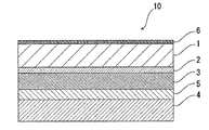
- a battery packaging material 10 of the present invention includes a polyester film layer 1, an aluminum alloy foil layer 3, and a heat-fusible resin layer 4 in this order, for example, as shown in FIG. It is composed of
- the polyester film layer 1 is the outermost layer side
- the heat-fusible resin layer 4 is the innermost layer. That is, when the battery is assembled, the battery element is sealed by heat-sealing the heat-fusible resin layers 4 positioned at the periphery of the battery element to seal the battery element.
- the battery packaging material of the present invention may include an adhesive layer 2 between the polyester film layer 1 and the aluminum alloy foil layer 3 as shown in FIG.
- an adhesive layer 5 may be provided between the aluminum alloy foil layer 3 and the heat-fusible resin layer 4.
- a surface coating layer 6 may be provided outside the polyester film layer 1 (on the side opposite to the heat-fusible resin layer 4) as necessary.
- the thickness of the laminate constituting the battery packaging material of the present invention is not particularly limited as long as it is 130 ⁇ m or less, but exhibits excellent moldability while reducing the thickness of the laminate as much as possible. From the viewpoint of effectively suppressing the curling due to the surface and enhancing the surface insulation, it is preferably about 110 to 130 ⁇ m, more preferably about 114 to 130 ⁇ m.
- the dielectric breakdown voltage of the surface of the battery packaging material of the present invention on the polyester film layer 1 side may be 13 kV or more, Preferably it is 14 kV or more, More preferably, 15 kV or more is mentioned.
- the dielectric breakdown voltage is a value measured in accordance with the provision of C2110-2: 2016, where the length of the test piece is 100 mm and the width is 100 mm. In addition, it measures using the thing whose electrode shape is a diameter 25mm cylinder / diameter 25mm cylinder.
- the breakdown voltage is specifically a value measured by the method described in the examples.
- the limit molding depth when molded under the following conditions is preferably about 4.0 mm or more, more preferably about 4.5 mm or more, and about 5.0 mm. More preferably, it is more preferably about 5.5 mm or more.
- the upper limit of the limit molding depth is usually about 10.0 mm.
- a rectangular battery packaging material having a length of 150 mm and a width of 100 mm is used as a test sample.
- this sample as a rectangular female mold having a diameter of 55 mm ⁇ 32 mm and a male mold corresponding to this, a molding depth of 0.5 mm from a molding depth of 0.5 mm at a pressing surface pressure of 0.23 MPa.
- cold forming is performed on 10 samples each.
- the test sample is placed on the female mold and molded so that the heat-fusible resin layer side is positioned on the male mold side.
- the clearance between the male mold and female mold is 0.5 mm.
- the battery packaging material of the present invention preferably has a curl measured under the following conditions of 40 mm or less.
- a rectangular battery packaging material having a length of 150 mm and a width of 100 mm is used as a test sample.
- This sample is cold-molded using a rectangular female die having a diameter of 55 mm ⁇ 32 mm and a male die corresponding to this with a pressing surface pressure of 0.23 MPa and a molding depth of 6 mm.
- the test sample is placed on the female mold and molded so that the heat-fusible resin layer side is positioned on the male mold side.
- the clearance between the male mold and female mold is 0.5 mm.
- the position of the molding part M is such that the shortest distance d between the rectangular molding part M formed by the mold and the end part P of the battery packaging material is 72 mm in the length direction of the battery packaging material, and In the width direction of the battery packaging material, the shortest distance between the molded part M and both ends of the battery packaging material is 34 mm.
- the battery packaging material after molding is placed on a horizontal plane so that the opening of the concave portion of the molding section faces downward, and the maximum value t in the vertical direction y from the horizontal plane to the end P is curled (mm ).
- a more specific method is as described in the examples.
- the polyester film layer 1 is a layer that is located on the outermost layer side and functions as a base material layer.
- Specific examples of the polyester constituting the polyester film layer 1 include co-polymers mainly composed of polyethylene terephthalate, polybutylene terephthalate, polyethylene naphthalate, polybutylene naphthalate, polyethylene isophthalate, polycarbonate, and ethylene terephthalate. Examples thereof include a polymerized polyester and a copolymerized polyester mainly composed of butylene terephthalate as a repeating unit.
- the copolymer polyester mainly composed of ethylene terephthalate is a copolymer polyester that polymerizes with ethylene isophthalate mainly composed of ethylene terephthalate (hereinafter, polyethylene (terephthalate / isophthalate)). Abbreviated), polyethylene (terephthalate / isophthalate), polyethylene (terephthalate / adipate), polyethylene (terephthalate / sodium sulfoisophthalate), polyethylene (terephthalate / sodium isophthalate), polyethylene (terephthalate / phenyl-dicarboxylate) And polyethylene (terephthalate / decanedicarboxylate).
- polyester mainly composed of butylene terephthalate as a repeating unit
- a copolymer polyester that polymerizes with butylene isophthalate having butylene terephthalate as a repeating unit hereinafter referred to as polybutylene (terephthalate / isophthalate).
- polybutylene (terephthalate / adipate) polybutylene (terephthalate / sebacate), polybutylene (terephthalate / decanedicarboxylate), polybutylene naphthalate and the like.
- These polyesters may be used individually by 1 type, and may be used in combination of 2 or more type. Polyester has an advantage that it has excellent resistance to electrolytic solution and is less likely to cause whitening due to the adhesion of the electrolytic solution, and is suitably used as a material for forming the polyester film layer 1.
- the polyester film layer 1 is preferably composed of a stretched polyester film such as a biaxially stretched polyester film, particularly a stretched polyethylene terephthalate film such as a biaxially stretched polyethylene terephthalate film.
- the thickness of the polyester film layer 1 needs to be 23 to 27 ⁇ m.
- the polyester film layer 1 as the base material layer and setting the thickness to 23 ⁇ m or more, it is possible to obtain a battery packaging material excellent in surface insulation having a dielectric breakdown voltage of 13 kV or more.
- 25 to 27 ⁇ m is preferable from the viewpoint of improving the surface insulation of the battery packaging material, and 23 to 25 ⁇ m is preferable from the viewpoint of suppressing curling due to molding.
- the dynamic friction coefficient of the surface on the polyester film layer 1 side is preferably 0.25 or less, more preferably 0.20 or less, and More preferably, it is from 05 to 0.20.
- the measuring method of a dynamic friction coefficient is a measuring method based on prescription
- a lubricant may be present on the surface of the polyester film layer 1 in order to set the dynamic friction coefficient of the surface of the polyester film layer 1 side to the above value.
- the amount of the lubricant is not particularly limited, but is preferably 3 mg / m 2 or more, more preferably 4 to 15 mg / m at a temperature of 24 ° C. and a relative humidity of 60%. 2 and more preferably 5 to 14 mg / m 2 .
- the polyester film layer 1 may contain a lubricant. Further, the lubricant present on the surface of the polyester film layer 1 may be one obtained by leaching the lubricant contained in the resin constituting the polyester film layer 1 or by applying a lubricant to the surface of the polyester film layer 1. It may be.
- the lubricant is not particularly limited, but preferably an amide lubricant.
- Specific examples of the lubricant include saturated fatty acid amide, unsaturated fatty acid amide, substituted amide, methylol amide, saturated fatty acid bisamide, unsaturated fatty acid bisamide and the like.
- Specific examples of the saturated fatty acid amide include lauric acid amide, palmitic acid amide, stearic acid amide, behenic acid amide, hydroxy stearic acid amide and the like.
- Specific examples of the unsaturated fatty acid amide include oleic acid amide and erucic acid amide.
- substituted amide examples include N-oleyl palmitic acid amide, N-stearyl stearic acid amide, N-stearyl oleic acid amide, N-oleyl stearic acid amide, N-stearyl erucic acid amide and the like.
- methylolamide examples include methylol stearamide.
- saturated fatty acid bisamides include methylene bis stearamide, ethylene biscapric amide, ethylene bis lauric acid amide, ethylene bis stearic acid amide, ethylene bishydroxy stearic acid amide, ethylene bisbehenic acid amide, hexamethylene bis stearic acid amide.
- acid amide hexamethylene bisbehenic acid amide, hexamethylene hydroxystearic acid amide, N, N′-distearyl adipic acid amide, N, N′-distearyl sebacic acid amide, and the like.
- unsaturated fatty acid bisamides include ethylene bisoleic acid amide, ethylene biserucic acid amide, hexamethylene bisoleic acid amide, N, N′-dioleyl adipic acid amide, N, N′-dioleyl sebacic acid amide Etc.
- Specific examples of the fatty acid ester amide include stearoamidoethyl stearate.
- aromatic bisamide examples include m-xylylene bis stearic acid amide, m-xylylene bishydroxy stearic acid amide, N, N′-distearyl isophthalic acid amide and the like.
- One type of lubricant may be used alone, or two or more types may be used in combination.
- the adhesive layer 2 is a layer provided between the polyester film layer 1 and the aluminum alloy foil layer 3 as necessary in order to firmly bond them.
- the adhesive layer 2 is formed of an adhesive capable of bonding the polyester film layer 1 and the aluminum alloy foil layer 3.
- the adhesive may be a two-component curable adhesive or a one-component curable adhesive.
- the bonding mechanism of the adhesive used for forming the adhesive layer 2 is not particularly limited, and may be any of a chemical reaction type, a solvent volatilization type, a heat melting type, a hot pressure type, and the like.
- adhesive components that can be used to form the adhesive layer 2 include polyester resins such as polyethylene terephthalate, polybutylene terephthalate, polyethylene naphthalate, polybutylene naphthalate, polyethylene isophthalate, polycarbonate, and copolyester; Polyether adhesives; Polyurethane adhesives; Epoxy resins; Phenol resins; Polyamide resins such as nylon 6, nylon 66, nylon 12, and copolymerized polyamides; Polyolefins such as polyolefins, carboxylic acid-modified polyolefins, and metal-modified polyolefins Resin, polyvinyl acetate resin; cellulose adhesive; (meth) acrylic resin; polyimide resin; amino resin such as urea resin and melamine resin; chloroprene rubber, nitrile rubber, styrene - rubbers such as butadiene rubber, silicone-based resins. These adhesive components may be used individually by 1 type, and may be used
- the thickness of the adhesive layer 2 is not particularly limited as long as it exhibits a function as an adhesive layer, and it is, for example, about 1 to 10 ⁇ m, preferably about 2 to 5 ⁇ m.
- the aluminum alloy foil layer 3 is a layer that functions as an aluminum alloy foil layer for preventing the entry of water vapor, oxygen, light, etc. into the battery, in addition to improving the strength of the battery packaging material. is there.
- the aluminum alloy foil layer 3 is made of an aluminum alloy.
- the aluminum alloy foil layer 3 is made of, for example, an annealed aluminum alloy (JIS H4160: 1994 A8021H-O, JIS H4160: 1994 A8079H-O, JIS H4000: 2014 A8021P-O, JIS H4000: 2014 A8079P-O) and the like are preferable, and among these, JIS H4160: 1994 A8021H-O It is particularly preferable that it is made of an aluminum alloy having a different composition.
- the thickness of the aluminum alloy foil layer 3 needs to be in the range of 33 to 37 ⁇ m. From the viewpoint of more effectively suppressing curling due to the molding of the battery packaging material, the thickness is preferably 35 to 37 ⁇ m.
- the aluminum alloy foil layer 3 is preferably subjected to chemical conversion treatment on at least one surface, preferably both surfaces, for the purpose of stabilizing adhesion, preventing dissolution and corrosion, and the like.
- the chemical conversion treatment refers to a treatment for forming an acid-resistant film on the surface of the aluminum alloy foil layer.
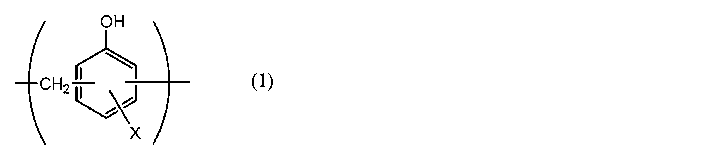
- chromic acid compounds such as chromium nitrate, chromium fluoride, chromium sulfate, chromium acetate, chromium oxalate, chromium biphosphate, chromic acetyl acetate, chromium chloride, potassium sulfate chromium, etc.
- X represents a hydrogen atom, a hydroxyl group, an alkyl group, a hydroxyalkyl group, an allyl group or a benzyl group.
- R 1 and R 2 are the same or different and each represents a hydroxyl group, an alkyl group, or a hydroxyalkyl group.
- examples of the alkyl group represented by X, R 1 and R 2 include a methyl group, an ethyl group, an n-propyl group, an isopropyl group, an n-butyl group, an isobutyl group, Examples thereof include a linear or branched alkyl group having 1 to 4 carbon atoms such as a tert-butyl group.
- Examples of the hydroxyalkyl group represented by X, R 1 and R 2 include a hydroxymethyl group, a 1-hydroxyethyl group, a 2-hydroxyethyl group, a 1-hydroxypropyl group, a 2-hydroxypropyl group, 3- C1-C4 straight or branched chain in which one hydroxy group such as hydroxypropyl group, 1-hydroxybutyl group, 2-hydroxybutyl group, 3-hydroxybutyl group, 4-hydroxybutyl group is substituted
- An alkyl group is mentioned.
- the alkyl group and hydroxyalkyl group represented by X, R 1 and R 2 may be the same or different.
- X is preferably a hydrogen atom, a hydroxyl group or a hydroxyalkyl group.
- the number average molecular weight of the aminated phenol polymer having a repeating unit represented by the general formulas (1) to (4) is, for example, preferably 500 to 1,000,000, and more preferably 1,000 to 20,000. .
- a coating in which fine particles of metal oxide such as aluminum oxide, titanium oxide, cerium oxide, tin oxide, or barium sulfate are dispersed in phosphoric acid is coated.
- the method of forming a corrosion-resistant process layer in the surface of the aluminum alloy foil layer 3 by baking at 150 degreeC or more is mentioned.
- a resin layer obtained by crosslinking a cationic polymer with a crosslinking agent may be further formed on the corrosion-resistant treatment layer.
- examples of the cationic polymer include polyethyleneimine, an ionic polymer complex composed of a polymer having polyethyleneimine and a carboxylic acid, a primary amine graft acrylic resin obtained by graft polymerization of a primary amine on an acrylic main skeleton, and polyallylamine. Or the derivative, aminophenol, etc. are mentioned.
- these cationic polymers only one type may be used, or two or more types may be used in combination.
- examples of the crosslinking agent include a compound having at least one functional group selected from the group consisting of an isocyanate group, a glycidyl group, a carboxyl group, and an oxazoline group, and a silane coupling agent. As these crosslinking agents, only one type may be used, or two or more types may be used in combination.
- chemical conversion treatment only one type of chemical conversion treatment may be performed, or two or more types of chemical conversion processing may be performed in combination. Furthermore, these chemical conversion treatments may be carried out using one kind of compound alone, or may be carried out using a combination of two or more kinds of compounds.
- chemical conversion treatments chromic acid chromate treatment, chromate treatment combining a chromic acid compound, a phosphoric acid compound, and an aminated phenol polymer are preferable.
- the amount of the acid-resistant film formed on the surface of the aluminum alloy foil layer 3 in the chemical conversion treatment is not particularly limited.
- Chromic acid compound in terms of chromium is 0.5 to 50 mg, preferably about 1.0 to 40 mg
- phosphorus compound is in terms of phosphorus, about 0.5 to 50 mg, preferably about 1.0 to 40 mg
- aminated phenol polymer Is preferably contained in a proportion of about 1 to 200 mg, preferably about 5.0 to 150 mg.
- the chemical conversion treatment is performed by applying a solution containing a compound used for forming an acid-resistant film to the surface of the aluminum alloy foil layer by a bar coating method, a roll coating method, a gravure coating method, a dipping method, etc. Is carried out by heating so that the temperature of 70 ° C. to 200 ° C. is reached.
- the aluminum alloy foil layer may be previously subjected to a degreasing treatment by an alkali dipping method, an electrolytic cleaning method, an acid cleaning method, an electrolytic acid cleaning method, or the like. By performing the degreasing treatment in this way, it is possible to more efficiently perform the chemical conversion treatment on the surface of the aluminum alloy foil layer.
- the heat-fusible resin layer 4 corresponds to the innermost layer, and is a layer that heat-fuses the heat-fusible resin layers and seals the battery element when the battery is assembled.
- the resin component used for the heat-fusible resin layer 4 is not particularly limited as long as it can be heat-sealed, and examples thereof include polyolefin, cyclic polyolefin, acid-modified polyolefin, and acid-modified cyclic polyolefin. That is, the heat-fusible resin layer 4 may or may not include a polyolefin skeleton, and preferably includes a polyolefin skeleton.
- the fact that the heat-fusible resin layer 4 contains a polyolefin skeleton can be analyzed by, for example, infrared spectroscopy, gas chromatography mass spectrometry, etc., and the analysis method is not particularly limited.
- a peak derived from maleic acid is detected in the vicinity of the wave number of 1760 cm -1 and near the wave number 1780 cm -1.
- the peak may be small and may not be detected. In that case, it can be analyzed by nuclear magnetic resonance spectroscopy.
- polystyrene resin examples include polyethylene such as low density polyethylene, medium density polyethylene, high density polyethylene, and linear low density polyethylene; homopolypropylene, polypropylene block copolymer (for example, block copolymer of propylene and ethylene), polypropylene And a random copolymer (eg, a random copolymer of propylene and ethylene); an ethylene-butene-propylene terpolymer; and the like.
- polyethylene and polypropylene are preferable, and random polypropylene is more preferable.
- the cyclic polyolefin is a copolymer of an olefin and a cyclic monomer
- examples of the olefin that is a constituent monomer of the cyclic polyolefin include ethylene, propylene, 4-methyl-1-pentene, styrene, butadiene, and isoprene. Is mentioned.
- Examples of the cyclic monomer that is a constituent monomer of the cyclic polyolefin include cyclic alkenes such as norbornene; specifically, cyclic dienes such as cyclopentadiene, dicyclopentadiene, cyclohexadiene, and norbornadiene.
- cyclic alkene is preferable, and norbornene is more preferable.
- the carboxylic acid-modified polyolefin is a polymer modified by block polymerization or graft polymerization of the polyolefin with carboxylic acid.
- Examples of the carboxylic acid used for modification include maleic acid, acrylic acid, itaconic acid, crotonic acid, maleic anhydride, itaconic anhydride and the like.
- the carboxylic acid-modified cyclic polyolefin is obtained by copolymerizing a part of the monomer constituting the cyclic polyolefin in place of the ⁇ , ⁇ -unsaturated carboxylic acid or its anhydride, or by ⁇ , ⁇ with respect to the cyclic polyolefin.
- the cyclic polyolefin to be modified with carboxylic acid is the same as described above.
- the carboxylic acid used for modification is the same as that used for modification of the polyolefin.
- the heat-fusible resin layer 4 is composed of a random polypropylene film.
- the heat-fusible resin layer 4 may be formed of one kind of resin component alone or may be formed of a blend polymer in which two or more kinds of resin components are combined. Furthermore, the heat-fusible resin layer 4 may be formed of only one layer, but may be formed of two or more layers using the same or different resin components.
- the thickness of the heat-fusible resin layer 4 needs to be about 55 to 65 ⁇ m. From the viewpoint of effectively suppressing curling after molding while further improving moldability, 57 About 60 ⁇ m is preferable.
- the dynamic friction coefficient of the surface on the heat-fusible resin layer 4 side is preferably about 0.25 or less, and is preferably about 0.20 or less. More preferably, it is about 0.05 to 0.20.
- the measuring method of a dynamic friction coefficient is a measuring method based on prescription
- a lubricant may be present on the surface of the heat-fusible resin layer 4 in order to set the dynamic friction coefficient of the surface of the heat-fusible resin layer 4 to the above value.
- the amount of the lubricant is not particularly limited, but is preferably about 3 mg / m 2 or more, more preferably 4 at a temperature of 24 ° C. and a relative humidity of 60%.
- About 15 to 15 mg / m 2 more preferably about 5 to 14 mg / m 2 .
- a lubricant may be contained in the heat-fusible resin layer 4. Further, the lubricant present on the surface of the heat-fusible resin layer 4 may be one in which a lubricant contained in the resin constituting the heat-fusible resin layer 4 is exuded, or the heat-fusible resin layer. 4 may be obtained by applying a lubricant to the surface.
- the lubricant is not particularly limited, and a known lubricant can be used, and examples thereof include those exemplified in the above polyester film layer 1.
- One type of lubricant may be used alone, or two or more types may be used in combination.
- the adhesive layer 5 is a layer provided between the aluminum alloy foil layer 3 and the heat-fusible resin layer 4 as necessary in order to firmly bond them.
- the adhesive layer 5 is formed of a resin capable of bonding the aluminum alloy foil layer 3 and the heat-fusible resin layer 4.
- the resin used for forming the adhesive layer 5 the same adhesive mechanism and the same types of adhesive components as those exemplified for the adhesive layer 2 can be used.
- polyolefin resins such as polyolefin, cyclic polyolefin, carboxylic acid-modified polyolefin, carboxylic acid-modified cyclic polyolefin exemplified in the above-mentioned heat-fusible resin layer 4 can also be used. .
- the polyolefin is preferably a carboxylic acid-modified polyolefin, and particularly preferably a carboxylic acid-modified polypropylene. That is, the adhesive layer 5 may or may not include a polyolefin skeleton, and preferably includes a polyolefin skeleton. The fact that the adhesive layer 5 contains a polyolefin skeleton can be analyzed by, for example, infrared spectroscopy, gas chromatography mass spectrometry, etc., and the analysis method is not particularly limited.
- a peak derived from maleic acid is detected in the vicinity of the wave number of 1760 cm -1 and near the wave number 1780 cm -1.
- the peak may be small and may not be detected. In that case, it can be analyzed by nuclear magnetic resonance spectroscopy.
- the adhesive layer 5 is made of an acid-modified polyolefin and cured.
- a cured product of a resin composition containing an agent may be used.
- Preferred examples of the acid-modified polyolefin include the same carboxylic acid-modified polyolefin and carboxylic acid-modified cyclic polyolefin exemplified in the heat-fusible resin layer 4.
- the curing agent is not particularly limited as long as it can cure the acid-modified polyolefin.
- the curing agent include an epoxy curing agent, a polyfunctional isocyanate curing agent, a carbodiimide curing agent, and an oxazoline curing agent.
- the epoxy curing agent is not particularly limited as long as it is a compound having at least one epoxy group.
- examples of the epoxy curing agent include epoxy resins such as bisphenol A diglycidyl ether, modified bisphenol A diglycidyl ether, novolac glycidyl ether, glycerin polyglycidyl ether, and polyglycerin polyglycidyl ether.
- the polyfunctional isocyanate curing agent is not particularly limited as long as it is a compound having two or more isocyanate groups.
- Specific examples of the polyfunctional isocyanate-based curing agent include isophorone diisocyanate (IPDI), hexamethylene diisocyanate (HDI), tolylene diisocyanate (TDI), diphenylmethane diisocyanate (MDI), those obtained by polymerizing or nurating these, Examples thereof include mixtures and copolymers with other polymers.
- the carbodiimide curing agent is not particularly limited as long as it is a compound having at least one carbodiimide group (—N ⁇ C ⁇ N—).
- a polycarbodiimide compound having at least two carbodiimide groups is preferable.
- the oxazoline-based curing agent is not particularly limited as long as it is a compound having an oxazoline skeleton.
- Specific examples of the oxazoline-based curing agent include Epocros series manufactured by Nippon Shokubai Co., Ltd.
- the curing agent may be composed of two or more kinds of compounds.
- the content of the curing agent in the resin composition forming the adhesive layer 5 is preferably in the range of 0.1 to 50% by mass, more preferably in the range of about 0.1 to 30% by mass. More preferably, it is in the range of about 1 to 10% by mass.
- the thickness of the adhesive layer 5 is not particularly limited as long as it functions as an adhesive layer. However, when the adhesive exemplified in the adhesive layer 2 is used, it is preferably about 2 to 10 ⁇ m, more preferably 2 to For example, about 5 ⁇ m. Further, when the resin exemplified in the heat-fusible resin layer 4 is used, it is preferably about 2 to 50 ⁇ m, more preferably about 10 to 40 ⁇ m. In the case of a cured product of an acid-modified polyolefin and a curing agent, it is preferably about 30 ⁇ m or less, more preferably about 0.1 to 20 ⁇ m, and still more preferably about 0.5 to 5 ⁇ m. When the adhesive layer 5 is a cured product of a resin composition containing an acid-modified polyolefin and a curing agent, the adhesive layer 5 can be formed by applying the resin composition and curing it by heating or the like.
- the polyester film layer 1 may be formed on the polyester film layer 1 as necessary (the aluminum alloy of the polyester film layer 1).
- a surface coating layer 6 may be provided on the side opposite to the foil layer 3 as necessary.
- the surface coating layer 6 is a layer located in the outermost layer when the battery is assembled.
- the surface coating layer 6 can be formed of, for example, polyvinylidene chloride, polyester resin, urethane resin, acrylic resin, epoxy resin, or the like. Of these, the surface coating layer 6 is preferably formed of a two-component curable resin. Examples of the two-component curable resin for forming the surface coating layer 6 include a two-component curable urethane resin, a two-component curable polyester resin, and a two-component curable epoxy resin. Moreover, you may mix
- Examples of the additive include fine particles having a particle diameter of 0.5 nm to 5 ⁇ m.
- the material of the additive is not particularly limited, and examples thereof include metals, metal oxides, inorganic substances, and organic substances.
- the shape of the additive is not particularly limited, and examples thereof include a spherical shape, a fibrous shape, a plate shape, an indeterminate shape, and a balloon shape.
- Specific additives include talc, silica, graphite, kaolin, montmorilloid, montmorillonite, synthetic mica, hydrotalcite, silica gel, zeolite, aluminum hydroxide, magnesium hydroxide, zinc oxide, magnesium oxide, aluminum oxide, Neodymium oxide, antimony oxide, titanium oxide, cerium oxide, calcium sulfate, barium sulfate, calcium carbonate, calcium silicate, lithium carbonate, calcium benzoate, calcium oxalate, magnesium stearate, alumina, carbon black, carbon nanotubes, high Melting
- money, aluminum, copper, nickel etc. are mentioned.
- additives may be used individually by 1 type, and may be used in combination of 2 or more type.
- silica, barium sulfate, and titanium oxide are preferably used from the viewpoints of dispersion stability and cost.
- the surface of the additive may be subjected to various surface treatments such as insulation treatment and high dispersibility treatment.
- the method for forming the surface coating layer 6 is not particularly limited, and examples thereof include a method of applying a two-component curable resin for forming the surface coating layer 6 on one surface of the polyester film layer 1.
- the additive may be added to the two-component curable resin, mixed, and then applied.
- the thickness of the surface coating layer 6 is not particularly limited as long as the above function as the surface coating layer 6 is exhibited.
- the thickness is about 0.5 to 10 ⁇ m, preferably about 1 to 5 ⁇ m.
- the production method of the battery packaging material of the present invention is not particularly limited as long as a laminate in which layers of a predetermined composition are laminated is obtained. That is, in the method for producing a battery packaging material of the present invention, at least the polyester film layer, the aluminum alloy foil layer, and the heat-fusible resin layer having the above thickness are laminated in this order. A step of obtaining a body.
- a laminate in which the polyester film layer 1, the adhesive layer 2, and the aluminum alloy foil layer 3 are laminated in order (hereinafter also referred to as “laminate A”) is formed.
- the laminate A is formed by applying an adhesive used for forming the adhesive layer 2 to the polyester film layer 1 or the aluminum alloy foil layer 3 whose surface is subjected to chemical conversion treatment, if necessary.
- a coating method such as a roll coating method
- the aluminum alloy foil layer 3 or the polyester film layer 1 can be laminated and the adhesive layer 2 can be cured by a dry laminating method.
- the adhesive layer 5 and the heat-fusible resin layer 4 are laminated on the aluminum alloy foil layer 3 of the laminate A in this order.
- a method of laminating the adhesive layer 5 and the heat-fusible resin layer 4 on the aluminum alloy foil layer 3 of the laminate A by co-extrusion (co-extrusion laminating method) (2) separate adhesion A method of forming a laminate in which the layer 5 and the heat-fusible resin layer 4 are laminated, and laminating the laminate on the aluminum alloy foil layer 3 of the laminate A by a thermal laminating method; (3) an aluminum alloy foil of the laminate A
- An adhesive for forming the adhesive layer 5 is laminated on the layer 3 by an extrusion method or a solution coating method, and is laminated by a method such as drying and baking at a high temperature.
- the surface coating layer 6 When the surface coating layer 6 is provided, the surface coating layer 6 is laminated on the surface of the polyester film layer 1 opposite to the aluminum alloy foil layer 3.
- the surface coating layer 6 can be formed, for example, by applying the above-described resin for forming the surface coating layer 6 to the surface of the polyester film layer 1.
- the order of the step of laminating the aluminum alloy foil layer 3 on the surface of the polyester film layer 1 and the step of laminating the surface coating layer 6 on the surface of the polyester film layer 1 are not particularly limited.
- the aluminum alloy foil layer 3 may be formed on the surface of the polyester film layer 1 opposite to the surface coating layer 6.
- a laminate comprising the layer 5 / the heat-fusible resin layer 4 is formed.
- a hot roll contact type, a hot air type, a near or You may use for heat processing, such as a far-infrared type. Examples of such heat treatment conditions include a temperature of about 150 to 250 ° C. and a time of about 1 to 5 minutes.
- each layer constituting the laminate improves or stabilizes film forming properties, lamination processing, suitability for final processing (pouching, embossing), etc., as necessary. Therefore, surface activation treatment such as corona treatment, blast treatment, oxidation treatment, ozone treatment may be performed.
- the battery packaging material of the present invention is used in a package for sealing and housing battery elements such as a positive electrode, a negative electrode, and an electrolyte. That is, a battery element including at least a positive electrode, a negative electrode, and an electrolyte can be accommodated in a package formed of the battery packaging material of the present invention to obtain a battery.
- a battery element including at least a positive electrode, a negative electrode, and an electrolyte is formed using the battery packaging material of the present invention, with the metal terminals connected to each of the positive electrode and the negative electrode protruding outward.
- a flange portion region where the heat-fusible resin layers are in contact with each other
- heat-sealing the heat-fusible resin layers of the flange portion to seal the battery
- a battery using the packaging material is provided.
- the battery packaging material of the present invention may be used for either a primary battery or a secondary battery, but is preferably a secondary battery.
- the type of secondary battery to which the battery packaging material of the present invention is applied is not particularly limited.
- a lithium ion battery, a lithium ion polymer battery, a lead storage battery, a nickel-hydrogen storage battery, a nickel-cadmium storage battery, a nickel- Examples include iron storage batteries, nickel / zinc storage batteries, silver oxide / zinc storage batteries, metal-air batteries, multivalent cation batteries, capacitors, capacitors, and the like.
- lithium ion batteries and lithium ion polymer batteries are suitable applications for the battery packaging material of the present invention.
- the battery packaging material of the present invention is excellent in formability while being thin, curling after molding is effectively suppressed, and can further impart sufficient surface insulation to the battery. Therefore, it can be suitably used for a large battery such as a vehicle battery.
- a battery to which the battery packaging material of the present invention can be suitably applied includes a large battery having a battery capacity of 30 Ah or more.
- the battery packaging material of the present invention can be suitably used for a battery used in a module in which a plurality of batteries are arranged.
- Example 1-52 and Comparative Example 1-146 ⁇ Manufacture of battery packaging materials>
- Each of the aluminum alloy foils made of aluminum alloy foil (JIS H4160: 1994 A8021H-O) subjected to chemical conversion treatment on both sides of the base material layer composed of the resin film described in Tables 1 to 4 is dry-laminated. Laminated by the method. Specifically, a two-component urethane adhesive (a polyol compound and an aromatic isocyanate compound) was applied to one surface of the aluminum alloy foil, and an adhesive layer (thickness 3 ⁇ m) was formed on the aluminum alloy foil layer. Next, after laminating the adhesive layer and the base material layer on the aluminum alloy foil, an aging treatment is carried out at 40 ° C.
- the chemical conversion treatment of the aluminum alloy foil is performed by a roll coating method in which a treatment liquid composed of a phenol resin, a chromium fluoride compound, and phosphoric acid is applied by a roll coating method so that a coating amount of chromium is 10 mg / m 2 (dry mass). It was performed by applying and baking on both sides of the foil.
- Test condition boosting method short-time method boosting speed; 0.5 kv / sec Ambient medium; air (23 ° C) Test electrode; 25 mm diameter cylinder / 25 mm diameter cylinder test environment; (23 ⁇ 2) ° C./(50 ⁇ 5)% RH
- the maximum height roughness (nominal value of Rz) specified in Table 2 of the piece is 3.2 ⁇ m) and a corresponding molding die (male mold, surface is attached to JIS B 0659-1: 2002) Document 1 (Reference)
- the maximum height roughness (nominal value of Rz) defined in Table 2 of the comparative surface roughness standard piece is 1.6 ⁇ m), and the pressing surface pressure is 0.23 MPa and the pressure is 0.
- the forming depth was changed in units of 0.5 mm from the forming depth of 5 mm, and cold forming (retraction one-step forming) was performed for each of 10 samples. At this time, the test sample was placed on the female mold and molded so that the heat-fusible resin layer side was positioned on the male mold side.
- Each battery packaging material obtained above was cut to produce a strip of length (z direction) 150 mm ⁇ width (x direction) 100 mm, which was used as a test sample.
- a rectangular female die having a diameter of 55 mm ⁇ 32 mm and a male die corresponding thereto, cold forming (retraction one-step forming) is performed at a pressing surface pressure of 0.23 MPa and a forming depth of 6 mm. It was.
- the test sample was placed on the female mold and molded so that the heat-fusible resin layer side was positioned on the male mold side. The clearance between the male mold and the female mold was 0.5 mm.
- the shortest distance d between the rectangular shaped portion M and the end portion P of the battery packaging material 10 is 72 mm, and in the width direction of the battery packaging material, the molded portion M and the battery packaging material.
- the molding was performed at a position where the shortest distance from both ends of the steel plate was 34 mm.
- the molded battery packaging material 10 is placed on the horizontal plane 20 as shown in FIG. 6, and the maximum curled portion t of the distance y in the vertical direction y from the horizontal plane 20 to the end P is curled.
- the height (molded curl (mm)) was used. The results are shown in Tables 1 to 4.
- PET is a stretched polyethylene terephthalate film
- ONy is a stretched nylon film
- PET / ONy is a laminate of PET and ONy (PET is located on the opposite side of the aluminum alloy foil layer, PET and ONy are bonded by an adhesive (polyester urethane, thickness 3 ⁇ m).
- PET / ONy (thickness 30 ⁇ m) uses PET 12 ⁇ m and ONy 15 ⁇ m.
- the polyester film layer The thickness of the aluminum alloy foil layer is 33 ⁇ m or more and 37 ⁇ m or less, the thickness of the heat-fusible resin layer is 55 ⁇ m or more and 65 ⁇ m or less, and the thickness of the laminate is 130 ⁇ m or less.
- the battery packaging materials of Examples 1 to 52 having specific configurations and thicknesses have high surface insulation properties such as a dielectric breakdown voltage of 13 kV or more on the surface on the polyester film layer side, and are excellent in moldability. It can be seen that curling after molding is also suppressed.
- Comparative Examples 1 to 146 are inferior to Examples 1 to 52 in at least one of the evaluation of surface insulation, moldability, and curl after molding. It turns out that is not demonstrated.
Abstract
Description
項1. 少なくとも、ポリエステルフィルム層、アルミニウム合金箔層、及び熱融着性樹脂層をこの順に備える積層体から構成されており、
前記ポリエステルフィルム層の厚みが、23μm以上、27μm以下であり、
前記アルミニウム合金箔層の厚みが、33μm以上、37μm以下であり、
前記熱融着性樹脂層の厚みが、55μm以上、65μm以下であり、
前記積層体の厚みが、130μm以下であり、
前記ポリエステルフィルム層の側の表面の絶縁破壊電圧が、13kV以上である、電池用包装材料。
項2. JIS K7125:1995の規定に準拠して測定される、前記ポリエステルフィルム層の側の表面の動摩擦係数が、0.25以下である、項1に記載の電池用包装材料。
項3. JIS K7125:1995の規定に準拠して測定される、前記熱融着性樹脂層の側の表面の動摩擦係数が、0.25以下である、項1または2に記載の電池用包装材料。
項4. 下記の条件で成形した際の限界成形深さが、4.0mm以上である、項1~3のいずれかに記載の電池用包装材料。
長さ150mm及び幅100mmの長方形の前記電池用包装材料を試験サンプルとする。このサンプルを55mm×32mmの口径を有する矩形状の雌型と、これに対応した雄型を用いて、押え面圧0.23MPaで0.5mmの成形深さから0.5mm単位で成形深さを変えて、それぞれ10個のサンプルについて冷間成形を行う。このとき、雄型側に熱融着性樹脂層側が位置するよう、雌型上に前記試験サンプルを載置して成形を行う。雄型及び雌型のクリアランスは、0.5mmとする。冷間成形後のサンプルについて、アルミニウム合金箔層にピンホールまたはクラックが10個のサンプル全てにおいて発生しない最も深い成形深さをA(mm)、アルミニウム合金箔層にピンホールまたはクラックが発生した最も浅い成形深さにおいて、ピンホールまたはクラックが発生したサンプルの数をB(個)とし、以下の式により算出される値を電池用包装材料の限界成形深さとする。
限界成形深さ=Amm+(0.5mm/10)×(10-B)
項5. 下記の条件で測定されるカールが、40mm以下である、項1~4のいずれかに記載の電池用包装材料。
長さ150mm及び幅100mmの長方形の前記電池用包装材料を試験サンプルとする。このサンプルを55mm×32mmの口径を有する矩形状の雌型と、これに対応した雄型を用いて、押え面圧0.23MPa、成形深さ6mmで冷間成形を行う。このとき、雄型側に熱融着性樹脂層側が位置するよう、雌型上に前記試験サンプルを載置して成形を行う。雄型及び雌型のクリアランスは、0.5mmとする。成形部Mの位置は、電池用包装材料の長さ方向において、金型によって形成される矩形状の成形部Mと、電池用包装材料の端部Pとの最短距離dが72mmとなり、かつ、電池用包装材料の幅方向において、当該成形部Mと電池用包装材料の両端部との最短距離が34mmとなる位置とする。成形後の電池用包装材料を、成形部の凹部の開口が下向きとなるようにして、水平面におき、当該水平面から、端部Pまでの垂直方向yの距離の最大値tを、カール(mm)とする。
項6. 前記ポリエステルフィルム層が、延伸ポリエチレンテレフタレートフィルムにより構成されている、項1~5のいずれかに記載の電池用包装材料。
項7. 前記熱融着性樹脂層が、ランダムポリプロピレンフィルムにより構成されている、項1~6のいずれかに記載の電池用包装材料。
項8. 前記アルミニウム合金箔層が、JIS H4160:1994 A8021H-Oに規定された組成を有するアルミニウム合金により構成されている、項1~7のいずれかに記載の電池用包装材料。
項9. 車両用電池に用いられる、項1~8のいずれかに記載の電池用包装材料。
項10. 正極、負極、及び電解質を備えた電池素子が、項1~9のいずれかに記載の電池用包装材料により形成された包装体中に収容されている、電池。 That is, this invention provides the invention of the aspect hung up below.
The thickness of the polyester film layer is 23 μm or more and 27 μm or less,
The aluminum alloy foil layer has a thickness of 33 μm or more and 37 μm or less,
The heat-fusible resin layer has a thickness of 55 μm or more and 65 μm or less,
The laminate has a thickness of 130 μm or less,
The battery packaging material whose dielectric breakdown voltage on the surface on the polyester film layer side is 13 kV or more.
A rectangular battery packaging material having a length of 150 mm and a width of 100 mm is used as a test sample. Using this sample as a rectangular female mold having a diameter of 55 mm × 32 mm and a male mold corresponding to this, a molding depth of 0.5 mm from a molding depth of 0.5 mm at a pressing surface pressure of 0.23 MPa. And cold forming is performed on 10 samples each. At this time, the test sample is placed on the female mold and molded so that the heat-fusible resin layer side is positioned on the male mold side. The clearance between the male mold and female mold is 0.5 mm. For samples after cold forming, the deepest forming depth at which no pinholes or cracks occurred in all 10 samples in the aluminum alloy foil layer was A (mm), and the pinholes or cracks occurred most in the aluminum alloy foil layer. The number of samples in which pinholes or cracks have occurred at a shallow molding depth is B (pieces), and the value calculated by the following formula is the critical molding depth of the battery packaging material.
Limit forming depth = Amm + (0.5mm / 10) × (10−B)
A rectangular battery packaging material having a length of 150 mm and a width of 100 mm is used as a test sample. This sample is cold-molded using a rectangular female die having a diameter of 55 mm × 32 mm and a male die corresponding to this with a pressing surface pressure of 0.23 MPa and a molding depth of 6 mm. At this time, the test sample is placed on the female mold and molded so that the heat-fusible resin layer side is positioned on the male mold side. The clearance between the male mold and female mold is 0.5 mm. The position of the molding part M is such that the shortest distance d between the rectangular molding part M formed by the mold and the end part P of the battery packaging material is 72 mm in the length direction of the battery packaging material, and In the width direction of the battery packaging material, the shortest distance between the molded part M and both ends of the battery packaging material is 34 mm. The battery packaging material after molding is placed on a horizontal plane so that the opening of the concave portion of the molding section faces downward, and the maximum value t in the vertical direction y from the horizontal plane to the end P is curled (mm ).
Item 7. Item 7. The battery packaging material according to any one of
Item 8. Item 8. The battery packaging material according to any one of
Item 9. Item 9. The battery packaging material according to any one of
本発明の電池用包装材料10は、例えば図1に示すように、ポリエステルフィルム層1、アルミニウム合金箔層3、及び熱融着性樹脂層4をこの順に備える積層体から構成されている。本発明の電池用包装材料において、ポリエステルフィルム層1が最外層側になり、熱融着性樹脂層4は最内層になる。即ち、電池の組み立て時に、電池素子の周縁に位置する熱融着性樹脂層4同士が熱融着して電池素子を密封することにより、電池素子が封止される。 1. Laminated structure of battery packaging material A
長さ150mm及び幅100mmの長方形の前記電池用包装材料を試験サンプルとする。このサンプルを55mm×32mmの口径を有する矩形状の雌型と、これに対応した雄型を用いて、押え面圧0.23MPaで0.5mmの成形深さから0.5mm単位で成形深さを変えて、それぞれ10個のサンプルについて冷間成形を行う。このとき、雄型側に熱融着性樹脂層側が位置するよう、雌型上に前記試験サンプルを載置して成形を行う。雄型及び雌型のクリアランスは、0.5mmとする。冷間成形後のサンプルについて、アルミニウム合金箔層にピンホールまたはクラックが10個のサンプル全てにおいて発生しない最も深い成形深さをAmm、アルミニウム合金箔層にピンホールまたはクラックが発生した最も浅い成形深さにおいて、ピンホールまたはクラックが発生したサンプルの数をB個とし、以下の式により算出される値を電池用包装材料の限界成形深さとする。より具体的な方法は、実施例に記載の通りである。
限界成形深さ=Amm+(0.5mm/10個)×(10個-B個) <Molding conditions>
A rectangular battery packaging material having a length of 150 mm and a width of 100 mm is used as a test sample. Using this sample as a rectangular female mold having a diameter of 55 mm × 32 mm and a male mold corresponding to this, a molding depth of 0.5 mm from a molding depth of 0.5 mm at a pressing surface pressure of 0.23 MPa. And cold forming is performed on 10 samples each. At this time, the test sample is placed on the female mold and molded so that the heat-fusible resin layer side is positioned on the male mold side. The clearance between the male mold and female mold is 0.5 mm. For samples after cold forming, the deepest forming depth at which no pinholes or cracks occurred in all 10 samples in the aluminum alloy foil layer was Amm, and the shallowest forming depth at which pinholes or cracks occurred in the aluminum alloy foil layer. Here, the number of samples in which pinholes or cracks have occurred is B, and the value calculated by the following equation is the critical molding depth of the battery packaging material. A more specific method is as described in the examples.
Limit forming depth = Amm + (0.5mm / 10) x (10-B)
長さ150mm及び幅100mmの長方形の電池用包装材料を試験サンプルとする。このサンプルを55mm×32mmの口径を有する矩形状の雌型と、これに対応した雄型を用いて、押え面圧0.23MPa、成形深さ6mmで冷間成形を行う。このとき、雄型側に熱融着性樹脂層側が位置するよう、雌型上に前記試験サンプルを載置して成形を行う。雄型及び雌型のクリアランスは、0.5mmとする。成形部Mの位置は、電池用包装材料の長さ方向において、金型によって形成される矩形状の成形部Mと、電池用包装材料の端部Pとの最短距離dが72mmとなり、かつ、電池用包装材料の幅方向において、当該成形部Mと電池用包装材料の両端部との最短距離が34mmとなる位置とする。成形後の電池用包装材料を、成形部の凹部の開口が下向きとなるようにして、水平面におき、当該水平面から、端部Pまでの垂直方向yの距離の最大値tを、カール(mm)とする。より具体的な方法は、実施例に記載の通りである。 <Measurement conditions of curl by molding>
A rectangular battery packaging material having a length of 150 mm and a width of 100 mm is used as a test sample. This sample is cold-molded using a rectangular female die having a diameter of 55 mm × 32 mm and a male die corresponding to this with a pressing surface pressure of 0.23 MPa and a molding depth of 6 mm. At this time, the test sample is placed on the female mold and molded so that the heat-fusible resin layer side is positioned on the male mold side. The clearance between the male mold and female mold is 0.5 mm. The position of the molding part M is such that the shortest distance d between the rectangular molding part M formed by the mold and the end part P of the battery packaging material is 72 mm in the length direction of the battery packaging material, and In the width direction of the battery packaging material, the shortest distance between the molded part M and both ends of the battery packaging material is 34 mm. The battery packaging material after molding is placed on a horizontal plane so that the opening of the concave portion of the molding section faces downward, and the maximum value t in the vertical direction y from the horizontal plane to the end P is curled (mm ). A more specific method is as described in the examples.
[ポリエステルフィルム層1]
本発明の電池用包装材料において、ポリエステルフィルム層1は、最外層側に位置し、基材層として機能する層である。ポリエステルフィルム層1を構成しているポリエステルとしては、具体的には、ポリエチレンテレフタレート、ポリブチレンテレフタレート、ポリエチレンナフタレート、ポリブチレンナフタレート、ポリエチレンイソフタレート、ポリカーボネート、エチレンテレフタレートを繰り返し単位の主体とした共重合ポリエステル、ブチレンテレフタレートを繰り返し単位の主体とした共重合ポリエステル等が挙げられる。また、エチレンテレフタレートを繰り返し単位の主体とした共重合ポリエステルとしては、具体的には、エチレンテレフタレートを繰り返し単位の主体としてエチレンイソフタレートと重合する共重合体ポリエステル(以下、ポリエチレン(テレフタレート/イソフタレート)にならって略す)、ポリエチレン(テレフタレート/イソフタレート)、ポリエチレン(テレフタレート/アジペート)、ポリエチレン(テレフタレート/ナトリウムスルホイソフタレート)、ポリエチレン(テレフタレート/ナトリウムイソフタレート)、ポリエチレン(テレフタレート/フェニル-ジカルボキシレート)、ポリエチレン(テレフタレート/デカンジカルボキシレート)等が挙げられる。また、ブチレンテレフタレートを繰り返し単位の主体とした共重合ポリエステルとしては、具体的には、ブチレンテレフタレートを繰り返し単位の主体としてブチレンイソフタレートと重合する共重合体ポリエステル(以下、ポリブチレン(テレフタレート/イソフタレート)にならって略す)、ポリブチレン(テレフタレート/アジペート)、ポリブチレン(テレフタレート/セバケート)、ポリブチレン(テレフタレート/デカンジカルボキシレート)、ポリブチレンナフタレート等が挙げられる。これらのポリエステルは、1種単独で使用してもよく、また2種以上を組み合わせて使用してもよい。ポリエステルは、耐電解液性に優れ、電解液の付着に対して白化等が発生し難いという利点があり、ポリエステルフィルム層1の形成素材として好適に使用される。 2. Each layer forming the battery packaging material [polyester film layer 1]
In the battery packaging material of the present invention, the
本発明の電池用包装材料において、接着剤層2は、ポリエステルフィルム層1とアルミニウム合金箔層3を強固に接着させるために、必要に応じて、これらの間に設けられる層である。 [Adhesive layer 2]
In the battery packaging material of the present invention, the
電池用包装材料において、アルミニウム合金箔層3は、電池用包装材料の強度向上の他、電池内部に水蒸気、酸素、光などが侵入することを防止するためのアルミニウム合金箔層として機能する層である。アルミニウム合金箔層3は、アルミニウム合金により構成されている。電池用包装材料の成形性をより一層高めつつ、成形によるカールを効果的に抑制する観点から、アルミニウム合金箔層3は、例えば、焼きなまし処理済みのアルミニウム合金(JIS H4160:1994 A8021H-O、JIS H4160:1994 A8079H-O、JIS H4000:2014 A8021P-O、JIS H4000:2014 A8079P-O)など軟質アルミニウム合金により構成されていることが好ましく、これらの中でも、JIS H4160:1994 A8021H-Oに規定された組成を有するアルミニウム合金により構成されていることが特に好ましい。 [Aluminum alloy foil layer 3]
In the battery packaging material, the aluminum


本発明の電池用包装材料において、熱融着性樹脂層4は、最内層に該当し、電池の組み立て時に熱融着性樹脂層同士が熱融着して電池素子を密封する層である。 [Heat-fusion resin layer 4]
In the battery packaging material of the present invention, the heat-
本発明の電池用包装材料において、接着層5は、アルミニウム合金箔層3と熱融着性樹脂層4を強固に接着させるために、必要に応じて、これらの間に設けられる層である。 [Adhesive layer 5]
In the battery packaging material of the present invention, the
本発明の電池用包装材料においては、意匠性、耐電解液性、耐擦過性、成形性の向上などを目的として、必要に応じて、ポリエステルフィルム層1の上(ポリエステルフィルム層1のアルミニウム合金箔層3とは反対側)に、必要に応じて、表面被覆層6を設けてもよい。表面被覆層6は、電池を組み立てた時に、最外層に位置する層である。 [Surface coating layer 6]
In the battery packaging material of the present invention, for the purpose of improving design properties, electrolytic solution resistance, scratch resistance, moldability, and the like, the
本発明の電池用包装材料の製造方法については、所定の組成の各層を積層させた積層体が得られる限り、特に制限されない。すなわち、本発明の電池用包装材料の製造方法においては、少なくとも、上記の厚みを有する、ポリエステルフィルム層、アルミニウム合金箔層、及び熱融着性樹脂層がこの順となるように積層して積層体を得る工程を備えている。 3. Production method of battery packaging material The production method of the battery packaging material of the present invention is not particularly limited as long as a laminate in which layers of a predetermined composition are laminated is obtained. That is, in the method for producing a battery packaging material of the present invention, at least the polyester film layer, the aluminum alloy foil layer, and the heat-fusible resin layer having the above thickness are laminated in this order. A step of obtaining a body.
本発明の電池用包装材料は、正極、負極、電解質等の電池素子を密封して収容するための包装体に使用される。すなわち、本発明の電池用包装材料によって形成された包装体中に、少なくとも正極、負極、及び電解質を備えた電池素子を収容して、電池とすることができる。 4). Application of Battery Packaging Material The battery packaging material of the present invention is used in a package for sealing and housing battery elements such as a positive electrode, a negative electrode, and an electrolyte. That is, a battery element including at least a positive electrode, a negative electrode, and an electrolyte can be accommodated in a package formed of the battery packaging material of the present invention to obtain a battery.
<電池用包装材料の製造>
それぞれ、表1~4に記載の樹脂フィルムにより構成されている基材層の上に、両面に化成処理を施したアルミニウム合金箔(JIS H4160:1994 A8021H-O)からなるアルミニウム合金箔をドライラミネート法により積層させた。具体的には、アルミニウム合金箔の一方面に、2液型ウレタン接着剤(ポリオール化合物と芳香族イソシアネート系化合物)を塗布し、アルミニウム合金箔層上に接着剤層(厚み3μm)を形成した。次いで、アルミニウム合金箔上の接着剤層と基材層を積層した後、40℃で24時間のエージング処理を実施することにより、基材層/接着剤層/アルミニウム合金箔層の積層体を作製した。なお、アルミニウム合金箔の化成処理は、フェノール樹脂、フッ化クロム化合物、及びリン酸からなる処理液をクロムの塗布量が10mg/m2(乾燥質量)となるように、ロールコート法によりアルミニウム合金箔の両面に塗布し、焼付けすることにより行った。 Example 1-52 and Comparative Example 1-146
<Manufacture of battery packaging materials>
Each of the aluminum alloy foils made of aluminum alloy foil (JIS H4160: 1994 A8021H-O) subjected to chemical conversion treatment on both sides of the base material layer composed of the resin film described in Tables 1 to 4 is dry-laminated. Laminated by the method. Specifically, a two-component urethane adhesive (a polyol compound and an aromatic isocyanate compound) was applied to one surface of the aluminum alloy foil, and an adhesive layer (
各電池用包装材料について、ポリエステルフィルム層側の表面及び熱融着性樹脂層側の表面の動摩擦係数を、それぞれ、JIS K7125:1995の規定に準拠して測定した。なお、各電池用包装材料を長さ(z方向)80mm×幅(x方向)200mmの長方形に2枚ずつ裁断して1組のサンプルとした。そして、1組のサンプルのポリエステルフィルム層の表面同士を重ね合わせて、ポリエステルフィルム層側の表面の動摩擦係数を測定した。熱融着性樹脂層側の表面の動摩擦係数についても、同じように、熱融着性樹脂層の表面同士を重ね合わせて測定した。結果を表1~4に示す。 <Measurement of dynamic friction coefficient>
About each battery packaging material, the dynamic friction coefficient of the surface by the side of a polyester film layer and the surface by the side of a heat-fusible resin layer was measured based on the prescription | regulation of JISK7125: 1995, respectively. Each battery packaging material was cut into two rectangles each having a length (z direction) of 80 mm × width (x direction) of 200 mm to form a set of samples. And the surface of the polyester film layer of 1 set of samples was piled up, and the dynamic friction coefficient of the surface by the side of a polyester film layer was measured. Similarly, the dynamic friction coefficient of the surface on the heat-fusible resin layer side was measured by superimposing the surfaces of the heat-fusible resin layer on each other. The results are shown in Tables 1 to 4.
上記で得られた各電池用包装材料の延伸ポリエチレンテレフタレートフィルム側の表面について、JIS C2110-2:2016の規定に準拠して、絶縁破壊電圧(kV)を測定した。試験片の長さを100mm、幅を100mmとした。絶縁破壊試験装置としては、YST-243-100RHO (ヤマヨ試験器社製)を使用した。結果を表1~4に示す。
試験条件
昇圧方式;短時間法
昇圧速度;0.5kv/sec
周囲媒質;大気(23℃)
試験電極;直径25mm円柱/直径25mm円柱
試験環境;(23±2)℃・(50±5)%RH <Measurement of breakdown voltage>
With respect to the surface of each battery packaging material obtained above on the side of the stretched polyethylene terephthalate film, the dielectric breakdown voltage (kV) was measured in accordance with the provisions of JIS C2110-2: 2016. The length of the test piece was 100 mm and the width was 100 mm. As the dielectric breakdown test apparatus, YST-243-100RHO (manufactured by Yamayo Tester) was used. The results are shown in Tables 1 to 4.
Test condition boosting method; short-time method boosting speed; 0.5 kv / sec
Ambient medium; air (23 ° C)
Test electrode; 25 mm diameter cylinder / 25 mm diameter cylinder test environment; (23 ± 2) ° C./(50±5)% RH
上記で得られた各電池用包装材料を長さ(z方向)150mm×幅(x方向)100mmの長方形に裁断して試験サンプルとした。このサンプルを32mm(x方向)×55mm(z方向)の口径を有する矩形状の成形金型(雌型、表面は、JIS B 0659-1:2002附属書1(参考) 比較用表面粗さ標準片の表2に規定される、最大高さ粗さ(Rzの呼び値)が3.2μmである)と、これに対応した成形金型(雄型、表面は、JIS B 0659-1:2002附属書1(参考) 比較用表面粗さ標準片の表2に規定される、最大高さ粗さ(Rzの呼び値)が1.6μmである)を用いて、押え面圧0.23MPaで0.5mmの成形深さから0.5mm単位で成形深さを変えて、それぞれ10個のサンプルについて冷間成形(引き込み1段成形)を行った。このとき、雄型側に熱融着性樹脂層側が位置するよう、雌型上に上記試験サンプルを載置して成形をおこなった。また、雄型及び雌型のクリアランスは、0.5mmとした。冷間成形後のサンプルについて、アルミニウム合金箔にピンホール、クラックが10個のサンプル全てにおいて発生しない最も深い成形深さをA(mm)、アルミニウム合金箔にピンホール等が発生した最も浅い成形深さにおいてピンホール等が発生したサンプルの数をB(個)とし、以下の式により算出される値を電池用包装材料の限界成形深さ(mm)とした。結果を表1~4に示す。
限界成形深さ=Amm+(0.5mm/10個)×(10個-B個) <Evaluation of formability>
Each of the battery packaging materials obtained above was cut into a rectangle of length (z direction) 150 mm × width (x direction) 100 mm to obtain a test sample. This sample was formed into a rectangular molding die having a diameter of 32 mm (x direction) × 55 mm (z direction) (female mold, the surface is JIS B 0659-1: 2002, Annex 1 (reference), surface roughness standard for comparison. The maximum height roughness (nominal value of Rz) specified in Table 2 of the piece is 3.2 μm) and a corresponding molding die (male mold, surface is attached to JIS B 0659-1: 2002) Document 1 (Reference) The maximum height roughness (nominal value of Rz) defined in Table 2 of the comparative surface roughness standard piece is 1.6 μm), and the pressing surface pressure is 0.23 MPa and the pressure is 0. The forming depth was changed in units of 0.5 mm from the forming depth of 5 mm, and cold forming (retraction one-step forming) was performed for each of 10 samples. At this time, the test sample was placed on the female mold and molded so that the heat-fusible resin layer side was positioned on the male mold side. The clearance between the male mold and the female mold was 0.5 mm. For the sample after cold forming, pinholes in the aluminum alloy foil, the deepest forming depth where cracks do not occur in all 10 samples are A (mm), and the shallowest forming depth in which pinholes are generated in the aluminum alloy foil In this case, the number of samples in which pinholes or the like were generated was defined as B (pieces), and the value calculated by the following formula was defined as the limit molding depth (mm) of the battery packaging material. The results are shown in Tables 1 to 4.
Limit forming depth = Amm + (0.5mm / 10) x (10-B)
上記で得られた各電池用包装材料を裁断して、長さ(z方向)150mm×幅(x方向)100mmの短冊片を作製し、これを試験サンプルとした。このサンプルを55mm×32mmの口径を有する矩形状の雌型と、これに対応した雄型を用いて、押え面圧0.23MPa、成形深さ6mmで冷間成形(引き込み1段成形)を行った。このとき、雄型側に熱融着性樹脂層側が位置するよう、雌型上に前記試験サンプルを載置して成形を行った。雄型及び雌型のクリアランスは、0.5mmとした。成形を行った位置の詳細は、図5に示される通りである。図5に示されるように、矩形状の成形部Mと電池用包装材料10の端部Pとの最短距離d=72mmかつ、電池用包装材料の幅方向において、成形部Mと電池用包装材料の両端部との最短距離が34mmとなる位置で成形した。次に、成形後の電池用包装材料10を、図6に示すようにして水平面20におき、水平面20から端部Pまでの垂直方向yの距離の最大値tをカールしている部分の最大高さ(成形カール(mm))とした。結果を表1~4に示す。 <Evaluation of curls after molding>
Each battery packaging material obtained above was cut to produce a strip of length (z direction) 150 mm × width (x direction) 100 mm, which was used as a test sample. Using this sample, a rectangular female die having a diameter of 55 mm × 32 mm and a male die corresponding thereto, cold forming (retraction one-step forming) is performed at a pressing surface pressure of 0.23 MPa and a forming depth of 6 mm. It was. At this time, the test sample was placed on the female mold and molded so that the heat-fusible resin layer side was positioned on the male mold side. The clearance between the male mold and the female mold was 0.5 mm. The details of the position where the molding is performed are as shown in FIG. As shown in FIG. 5, the shortest distance d between the rectangular shaped portion M and the end portion P of the
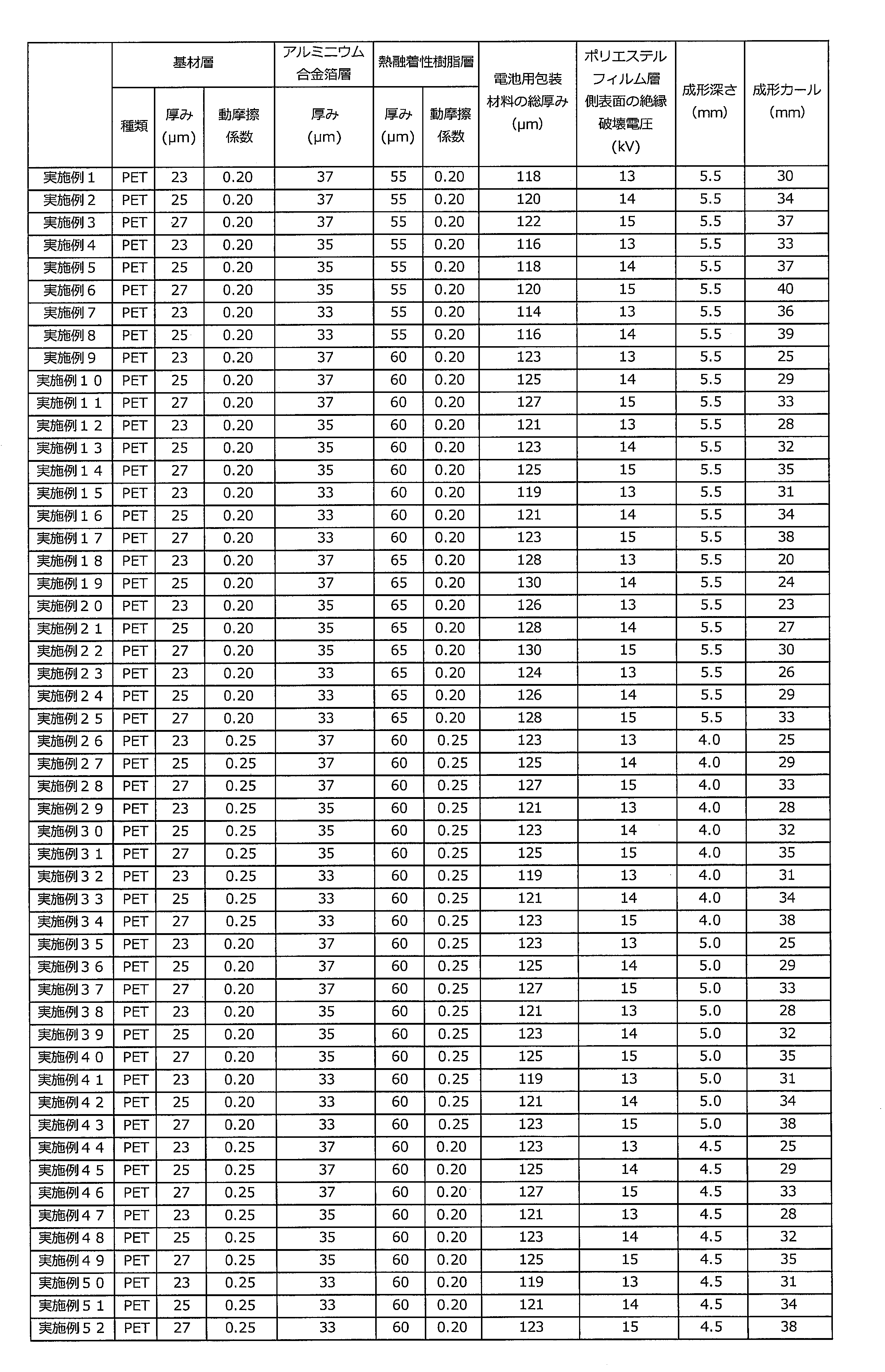
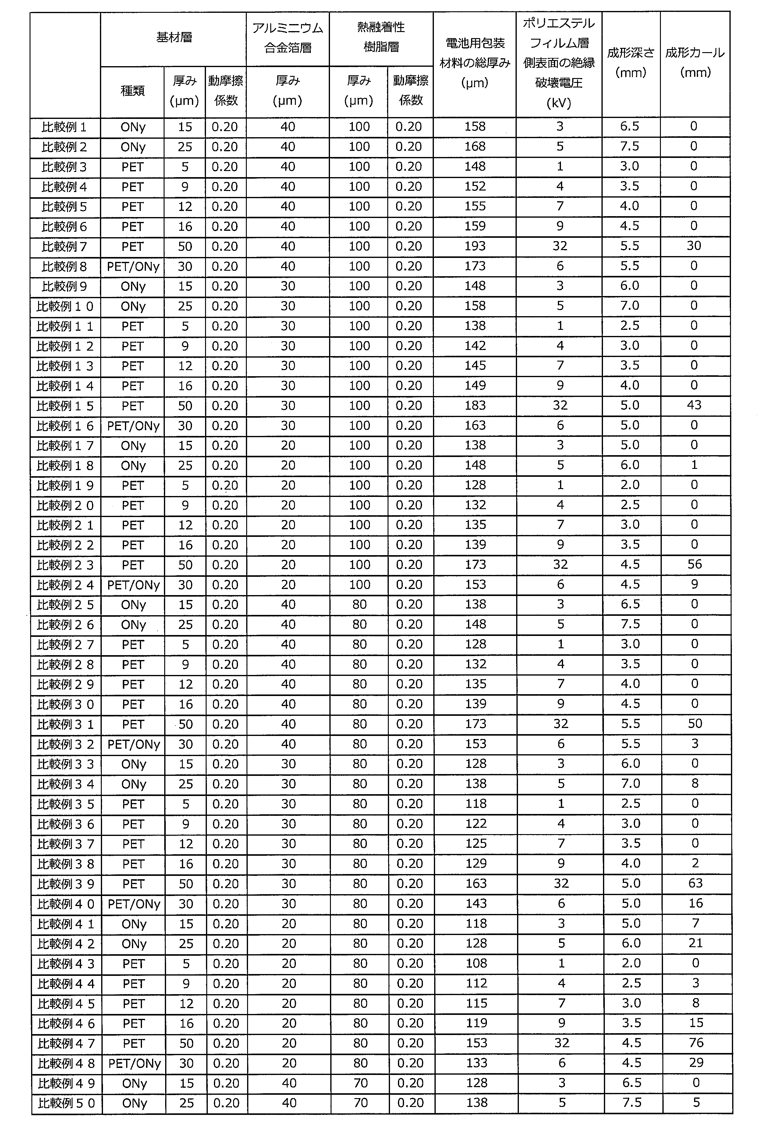


2 接着剤層
3 アルミニウム合金箔層
4 熱融着性樹脂層
5 接着層
6 表面被覆層
10 電池用包装材料
20 水平面
d 成形部と電池用包装材料の端部との最短距離
M 成形部
P 電池用包装材料の端部
t 水平面から端部までの垂直方向の距離の最大値 DESCRIPTION OF
Claims (10)
- 少なくとも、ポリエステルフィルム層、アルミニウム合金箔層、及び熱融着性樹脂層をこの順に備える積層体から構成されており、
前記ポリエステルフィルム層の厚みが、23μm以上、27μm以下であり、
前記アルミニウム合金箔層の厚みが、33μm以上、37μm以下であり、
前記熱融着性樹脂層の厚みが、55μm以上、65μm以下であり、
前記積層体の厚みが、130μm以下であり、
前記ポリエステルフィルム層の側の表面の絶縁破壊電圧が、13kV以上である、電池用包装材料。 It is composed of a laminate comprising at least a polyester film layer, an aluminum alloy foil layer, and a heat-fusible resin layer in this order,
The thickness of the polyester film layer is 23 μm or more and 27 μm or less,
The aluminum alloy foil layer has a thickness of 33 μm or more and 37 μm or less,
The heat-fusible resin layer has a thickness of 55 μm or more and 65 μm or less,
The laminate has a thickness of 130 μm or less,
The battery packaging material whose dielectric breakdown voltage on the surface on the polyester film layer side is 13 kV or more. - JIS K7125:1995の規定に準拠して測定される、前記ポリエステルフィルム層の側の表面の動摩擦係数が、0.25以下である、請求項1に記載の電池用包装材料。 The battery packaging material according to claim 1, wherein a dynamic friction coefficient of the surface on the polyester film layer side measured in accordance with JIS K7125: 1995 is 0.25 or less.
- JIS K7125:1995の規定に準拠して測定される、前記熱融着性樹脂層の側の表面の動摩擦係数が、0.25以下である、請求項1または2に記載の電池用包装材料。 The battery packaging material according to claim 1 or 2, wherein a coefficient of dynamic friction of the surface on the side of the heat-fusible resin layer, measured in accordance with JIS K7125: 1995, is 0.25 or less.
- 下記の条件で成形した際の限界成形深さが、4.0mm以上である、請求項1~3のいずれかに記載の電池用包装材料。
長さ150mm及び幅100mmの長方形の前記電池用包装材料を試験サンプルとする。このサンプルを55mm×32mmの口径を有する矩形状の雌型と、これに対応した雄型を用いて、押え面圧0.23MPaで0.5mmの成形深さから0.5mm単位で成形深さを変えて、それぞれ10個のサンプルについて冷間成形を行う。このとき、雄型側に熱融着性樹脂層側が位置するよう、雌型上に前記試験サンプルを載置して成形を行う。雄型及び雌型のクリアランスは、0.5mmとする。冷間成形後のサンプルについて、アルミニウム合金箔層にピンホールまたはクラックが10個のサンプル全てにおいて発生しない最も深い成形深さをA(mm)、アルミニウム合金箔層にピンホールまたはクラックが発生した最も浅い成形深さにおいて、ピンホールまたはクラックが発生したサンプルの数をB(個)とし、以下の式により算出される値を電池用包装材料の限界成形深さとする。
限界成形深さ=Amm+(0.5mm/10)×(10-B) The battery packaging material according to any one of claims 1 to 3, wherein a limit molding depth when molded under the following conditions is 4.0 mm or more.
A rectangular battery packaging material having a length of 150 mm and a width of 100 mm is used as a test sample. Using this sample as a rectangular female mold having a diameter of 55 mm × 32 mm and a male mold corresponding to this, a molding depth of 0.5 mm from a molding depth of 0.5 mm at a pressing surface pressure of 0.23 MPa. And cold forming is performed on 10 samples each. At this time, the test sample is placed on the female mold and molded so that the heat-fusible resin layer side is positioned on the male mold side. The clearance between the male mold and female mold is 0.5 mm. For samples after cold forming, the deepest forming depth at which no pinholes or cracks occurred in all 10 samples in the aluminum alloy foil layer was A (mm), and the pinholes or cracks occurred most in the aluminum alloy foil layer. The number of samples in which pinholes or cracks have occurred at a shallow molding depth is B (pieces), and the value calculated by the following formula is the critical molding depth of the battery packaging material.
Limit forming depth = Amm + (0.5mm / 10) × (10−B) - 下記の条件で測定されるカールが、40mm以下である、請求項1~4のいずれかに記載の電池用包装材料。
長さ150mm及び幅100mmの長方形の前記電池用包装材料を試験サンプルとする。このサンプルを55mm×32mmの口径を有する矩形状の雌型と、これに対応した雄型を用いて、押え面圧0.23MPa、成形深さ6mmで冷間成形を行う。このとき、雄型側に熱融着性樹脂層側が位置するよう、雌型上に前記試験サンプルを載置して成形を行う。雄型及び雌型のクリアランスは、0.5mmとする。成形部Mの位置は、電池用包装材料の長さ方向において、金型によって形成される矩形状の成形部Mと、電池用包装材料の端部Pとの最短距離dが72mmとなり、かつ、電池用包装材料の幅方向において、当該成形部Mと電池用包装材料の両端部との最短距離が34mmとなる位置とする。成形後の電池用包装材料を、成形部の凹部の開口が下向きとなるようにして、水平面におき、当該水平面から、端部Pまでの垂直方向yの距離の最大値tを、カール(mm)とする。 The battery packaging material according to any one of claims 1 to 4, wherein the curl measured under the following conditions is 40 mm or less.
A rectangular battery packaging material having a length of 150 mm and a width of 100 mm is used as a test sample. This sample is cold-molded using a rectangular female die having a diameter of 55 mm × 32 mm and a male die corresponding to this with a pressing surface pressure of 0.23 MPa and a molding depth of 6 mm. At this time, the test sample is placed on the female mold and molded so that the heat-fusible resin layer side is positioned on the male mold side. The clearance between the male mold and female mold is 0.5 mm. The position of the molding part M is such that the shortest distance d between the rectangular molding part M formed by the mold and the end part P of the battery packaging material is 72 mm in the length direction of the battery packaging material, and In the width direction of the battery packaging material, the shortest distance between the molded part M and both ends of the battery packaging material is 34 mm. The battery packaging material after molding is placed on a horizontal plane so that the opening of the concave portion of the molding section faces downward, and the maximum value t in the vertical direction y from the horizontal plane to the end P is curled (mm ). - 前記ポリエステルフィルム層が、延伸ポリエチレンテレフタレートフィルムにより構成されている、請求項1~5のいずれかに記載の電池用包装材料。 The battery packaging material according to any one of claims 1 to 5, wherein the polyester film layer is composed of a stretched polyethylene terephthalate film.
- 前記熱融着性樹脂層が、ランダムポリプロピレンフィルムにより構成されている、請求項1~6のいずれかに記載の電池用包装材料。 The battery packaging material according to any one of claims 1 to 6, wherein the heat-fusible resin layer is made of a random polypropylene film.
- 前記アルミニウム合金箔層が、JIS H4160:1994 A8021H-Oに規定された組成を有するアルミニウム合金により構成されている、請求項1~7のいずれかに記載の電池用包装材料。 The battery packaging material according to any one of claims 1 to 7, wherein the aluminum alloy foil layer is made of an aluminum alloy having a composition defined in JIS H4160: 1994 A8021H-O.
- 車両用電池に用いられる、請求項1~8のいずれかに記載の電池用包装材料。 The battery packaging material according to any one of claims 1 to 8, which is used for a vehicle battery.
- 正極、負極、及び電解質を備えた電池素子が、請求項1~9のいずれかに記載の電池用包装材料により形成された包装体中に収容されている、電池。 A battery in which a battery element including a positive electrode, a negative electrode, and an electrolyte is accommodated in a package formed of the battery packaging material according to any one of claims 1 to 9.
Priority Applications (6)
| Application Number | Priority Date | Filing Date | Title |
|---|---|---|---|
| JP2018532013A JP6597907B2 (en) | 2016-08-05 | 2017-08-04 | Battery packaging material and battery |
| CN201780047769.0A CN109564993B (en) | 2016-08-05 | 2017-08-04 | Battery packaging material and battery |
| EP17837108.4A EP3496178A4 (en) | 2016-08-05 | 2017-08-04 | Battery packaging material and battery |
| KR1020197035468A KR102318004B1 (en) | 2016-08-05 | 2017-08-04 | Battery packaging material and battery |
| US16/322,257 US10985419B2 (en) | 2016-08-05 | 2017-08-04 | Battery packaging material and battery |
| KR1020197003850A KR20190018741A (en) | 2016-08-05 | 2017-08-04 | Cell packing materials and batteries |
Applications Claiming Priority (2)
| Application Number | Priority Date | Filing Date | Title |
|---|---|---|---|
| JP2016155077 | 2016-08-05 | ||
| JP2016-155077 | 2016-08-05 |
Publications (1)
| Publication Number | Publication Date |
|---|---|
| WO2018026007A1 true WO2018026007A1 (en) | 2018-02-08 |
Family
ID=61073161
Family Applications (1)
| Application Number | Title | Priority Date | Filing Date |
|---|---|---|---|
| PCT/JP2017/028446 WO2018026007A1 (en) | 2016-08-05 | 2017-08-04 | Battery packaging material and battery |
Country Status (6)
| Country | Link |
|---|---|
| US (1) | US10985419B2 (en) |
| EP (1) | EP3496178A4 (en) |
| JP (1) | JP6597907B2 (en) |
| KR (2) | KR102318004B1 (en) |
| CN (1) | CN109564993B (en) |
| WO (1) | WO2018026007A1 (en) |
Families Citing this family (3)
| Publication number | Priority date | Publication date | Assignee | Title |
|---|---|---|---|---|
| CN114902472A (en) * | 2019-12-25 | 2022-08-12 | 大日本印刷株式会社 | Outer packaging material for electricity storage device, method for producing same, and electricity storage device |
| JP7437609B2 (en) * | 2020-04-02 | 2024-02-26 | トヨタ自動車株式会社 | Laminated power storage device and its short circuit inspection method |
| CN113594593B (en) * | 2021-07-12 | 2023-06-20 | 苏州福斯特光伏材料有限公司 | Design method of aluminum plastic film and aluminum plastic film |
Citations (7)
| Publication number | Priority date | Publication date | Assignee | Title |
|---|---|---|---|---|
| JPH08191023A (en) * | 1994-08-26 | 1996-07-23 | Hitachi Ltd | Resin molded coil, manufacturing method thereof and transformer |
| JP2008287971A (en) | 2007-05-16 | 2008-11-27 | Sony Corp | Layered package material, outer package material for battery, and the battery |
| JP2013201027A (en) | 2012-03-26 | 2013-10-03 | Hitachi Ltd | Battery module and battery system using the same |
| JP2013222545A (en) * | 2012-04-13 | 2013-10-28 | Toppan Printing Co Ltd | Outer packaging material for lithium ion battery |
| WO2014069236A1 (en) * | 2012-10-31 | 2014-05-08 | 東レ株式会社 | Polyester film, laminate produced using said film, and structure comprising said laminate and sealant layer |
| JP2015106528A (en) * | 2013-12-02 | 2015-06-08 | 大日本印刷株式会社 | Battery-packaging material |
| JP2016071952A (en) * | 2014-09-26 | 2016-05-09 | 大日本印刷株式会社 | Battery-packaging material |
Family Cites Families (25)
| Publication number | Priority date | Publication date | Assignee | Title |
|---|---|---|---|---|
| EP0975031B2 (en) | 1998-02-05 | 2011-11-02 | Dai Nippon Printing Co., Ltd. | Sheet for cell case and cell device |
| JP4433506B2 (en) * | 1998-11-06 | 2010-03-17 | 株式会社ジーエス・ユアサコーポレーション | battery |
| JP2006066113A (en) | 2004-08-25 | 2006-03-09 | Toppan Printing Co Ltd | Laminating material and outer packaging for battery using laminating material |
| JP4984386B2 (en) | 2004-11-01 | 2012-07-25 | 日産自動車株式会社 | Battery structure |
| JP5211622B2 (en) * | 2007-01-31 | 2013-06-12 | 凸版印刷株式会社 | Lithium battery packaging material and method for producing the same |
| JP5114260B2 (en) * | 2007-03-30 | 2013-01-09 | 大日本印刷株式会社 | Packaging material for flat electrochemical cells |
| CN102157582A (en) * | 2011-01-20 | 2011-08-17 | 山东舜亦新能源有限公司 | Packaging technology in module production process |
| JP6065367B2 (en) * | 2011-06-07 | 2017-01-25 | ソニー株式会社 | Nonaqueous electrolyte battery, battery pack, electronic device, electric vehicle, power storage device, and power system |
| JP5755975B2 (en) * | 2011-09-01 | 2015-07-29 | 昭和電工パッケージング株式会社 | Battery exterior material and lithium secondary battery |
| JP5957913B2 (en) * | 2012-01-31 | 2016-07-27 | 凸版印刷株式会社 | Secondary battery electrode terminals |
| JP6035156B2 (en) * | 2012-03-19 | 2016-11-30 | 昭和電工パッケージング株式会社 | Molding packaging material and molding case |
| JP6005976B2 (en) * | 2012-04-24 | 2016-10-12 | 昭和電工パッケージング株式会社 | Water-based surface treatment agent for lamination, surface treatment method, and surface treatment material |
| CN202996917U (en) * | 2012-11-28 | 2013-06-12 | 东莞市芯能新材料有限公司 | Improved type lithium battery flexible packaging film |
| JP6255258B2 (en) * | 2013-03-05 | 2017-12-27 | 昭和電工パッケージング株式会社 | Molding packaging material and molding case |
| CN105556699B (en) * | 2013-09-20 | 2020-06-09 | 大日本印刷株式会社 | Packaging material for battery |
| CN105794012B (en) * | 2013-12-02 | 2019-06-25 | 大日本印刷株式会社 | Battery use packing material |
| DE102014201157A1 (en) * | 2014-01-23 | 2015-07-23 | Robert Bosch Gmbh | Electrochemical energy storage |
| JP6717190B2 (en) | 2014-04-09 | 2020-07-01 | 凸版印刷株式会社 | Power storage device exterior material, power storage device, and method for manufacturing embossed type exterior material |
| CN106663755B (en) | 2014-08-28 | 2019-09-03 | 大日本印刷株式会社 | Battery use packing material |
| JP6492497B2 (en) * | 2014-09-30 | 2019-04-03 | 大日本印刷株式会社 | Battery packaging materials |
| CN113410552B (en) | 2014-09-30 | 2023-02-21 | 大日本印刷株式会社 | Battery packaging material and battery |
| CN104485430B (en) * | 2014-12-11 | 2016-12-07 | 乐凯胶片股份有限公司 | A kind of lithium battery flexible packaging film |
| US10541390B2 (en) * | 2015-05-18 | 2020-01-21 | Semiconductor Energy Laboratory Co., Ltd. | Power storage unit and electronic device |
| TWI691113B (en) * | 2015-07-01 | 2020-04-11 | 日商昭和電工包裝股份有限公司 | Exterior materials for power storage device and power storage device |
| US11038228B2 (en) * | 2016-07-22 | 2021-06-15 | Envision Aesc Energy Devices Ltd. | Electrochemical device having a thermally fusible resin layer |
-
2017
- 2017-08-04 JP JP2018532013A patent/JP6597907B2/en active Active
- 2017-08-04 US US16/322,257 patent/US10985419B2/en active Active
- 2017-08-04 KR KR1020197035468A patent/KR102318004B1/en active IP Right Grant
- 2017-08-04 EP EP17837108.4A patent/EP3496178A4/en active Pending
- 2017-08-04 WO PCT/JP2017/028446 patent/WO2018026007A1/en unknown
- 2017-08-04 CN CN201780047769.0A patent/CN109564993B/en active Active
- 2017-08-04 KR KR1020197003850A patent/KR20190018741A/en not_active Application Discontinuation
Patent Citations (7)
| Publication number | Priority date | Publication date | Assignee | Title |
|---|---|---|---|---|
| JPH08191023A (en) * | 1994-08-26 | 1996-07-23 | Hitachi Ltd | Resin molded coil, manufacturing method thereof and transformer |
| JP2008287971A (en) | 2007-05-16 | 2008-11-27 | Sony Corp | Layered package material, outer package material for battery, and the battery |
| JP2013201027A (en) | 2012-03-26 | 2013-10-03 | Hitachi Ltd | Battery module and battery system using the same |
| JP2013222545A (en) * | 2012-04-13 | 2013-10-28 | Toppan Printing Co Ltd | Outer packaging material for lithium ion battery |
| WO2014069236A1 (en) * | 2012-10-31 | 2014-05-08 | 東レ株式会社 | Polyester film, laminate produced using said film, and structure comprising said laminate and sealant layer |
| JP2015106528A (en) * | 2013-12-02 | 2015-06-08 | 大日本印刷株式会社 | Battery-packaging material |
| JP2016071952A (en) * | 2014-09-26 | 2016-05-09 | 大日本印刷株式会社 | Battery-packaging material |
Non-Patent Citations (1)
| Title |
|---|
| See also references of EP3496178A4 |
Also Published As
| Publication number | Publication date |
|---|---|
| CN109564993B (en) | 2022-04-29 |
| US10985419B2 (en) | 2021-04-20 |
| EP3496178A4 (en) | 2020-03-25 |
| CN109564993A (en) | 2019-04-02 |
| KR20190018741A (en) | 2019-02-25 |
| JPWO2018026007A1 (en) | 2019-06-06 |
| US20190198826A1 (en) | 2019-06-27 |
| KR102318004B1 (en) | 2021-10-26 |
| KR20190136119A (en) | 2019-12-09 |
| JP6597907B2 (en) | 2019-10-30 |
| EP3496178A1 (en) | 2019-06-12 |
Similar Documents
| Publication | Publication Date | Title |
|---|---|---|
| KR102551200B1 (en) | Battery packaging material, production method therefor, battery, and polyester film | |
| JP6648863B2 (en) | Battery packaging material, method for producing the same, and battery | |
| JP6566133B2 (en) | Battery packaging material, method for producing the same, battery, and polyester film | |
| JP6679918B2 (en) | Battery packaging material | |
| WO2017131155A1 (en) | Packaging material and cell | |
| WO2018174056A1 (en) | Packaging material for batteries, method for producing same, polybutylene terephthalate film for packaging material for batteries, and battery | |
| JP6492497B2 (en) | Battery packaging materials | |
| JP2019029300A (en) | Battery-packaging material, method for manufacturing the same, and battery | |
| JP7314970B2 (en) | BATTERY PACKAGING MATERIAL, MANUFACTURING METHOD THEREOF, AND BATTERY | |
| CN109075270B (en) | Battery packaging material and battery | |
| JP2016171078A (en) | Packaging material for cell | |
| JP6597907B2 (en) | Battery packaging material and battery | |
| WO2017175837A1 (en) | Battery packaging material, method for manufacturing same, and battery | |
| JP6736837B2 (en) | Battery packaging material | |
| WO2019074016A1 (en) | Poly(butylene terephthalate) film, packaging material for batteries, method for producing packaging material for batteries, and battery | |
| JP2019016537A (en) | Packaging material for battery, manufacturing method thereof, and battery | |
| CN115066792A (en) | Outer packaging material for electricity storage device, method for producing same, and electricity storage device | |
| CN115443577A (en) | Outer packaging material for electricity storage device, method for producing same, and electricity storage device |
Legal Events
| Date | Code | Title | Description |
|---|---|---|---|
| 121 | Ep: the epo has been informed by wipo that ep was designated in this application |
Ref document number: 17837108 Country of ref document: EP Kind code of ref document: A1 |
|
| ENP | Entry into the national phase |
Ref document number: 2018532013 Country of ref document: JP Kind code of ref document: A |
|
| NENP | Non-entry into the national phase |
Ref country code: DE |
|
| ENP | Entry into the national phase |
Ref document number: 20197003850 Country of ref document: KR Kind code of ref document: A |
|
| ENP | Entry into the national phase |
Ref document number: 2017837108 Country of ref document: EP Effective date: 20190305 |