WO2018024804A1 - A household appliance having a movable drawer - Google Patents
A household appliance having a movable drawer Download PDFInfo
- Publication number
- WO2018024804A1 WO2018024804A1 PCT/EP2017/069594 EP2017069594W WO2018024804A1 WO 2018024804 A1 WO2018024804 A1 WO 2018024804A1 EP 2017069594 W EP2017069594 W EP 2017069594W WO 2018024804 A1 WO2018024804 A1 WO 2018024804A1
- Authority
- WO
- WIPO (PCT)
- Prior art keywords
- tray
- household appliance
- drawer
- cavity
- male part
- Prior art date
Links
Images


Classifications
-
- A—HUMAN NECESSITIES
- A47—FURNITURE; DOMESTIC ARTICLES OR APPLIANCES; COFFEE MILLS; SPICE MILLS; SUCTION CLEANERS IN GENERAL
- A47J—KITCHEN EQUIPMENT; COFFEE MILLS; SPICE MILLS; APPARATUS FOR MAKING BEVERAGES
- A47J39/00—Heat-insulated warming chambers; Cupboards with heating arrangements for warming kitchen utensils
- A47J39/006—Heat-insulated warming chambers; Cupboards with heating arrangements for warming kitchen utensils for either storing and preparing or for preparing food on serving trays, e.g. heating, thawing, preserving
-
- F—MECHANICAL ENGINEERING; LIGHTING; HEATING; WEAPONS; BLASTING
- F24—HEATING; RANGES; VENTILATING
- F24C—DOMESTIC STOVES OR RANGES ; DETAILS OF DOMESTIC STOVES OR RANGES, OF GENERAL APPLICATION
- F24C15/00—Details
- F24C15/18—Arrangement of compartments additional to cooking compartments, e.g. for warming or for storing utensils or fuel containers; Arrangement of additional heating or cooking apparatus, e.g. grills
Landscapes
- Engineering & Computer Science (AREA)
- Food Science & Technology (AREA)
- Chemical & Material Sciences (AREA)
- Combustion & Propulsion (AREA)
- Mechanical Engineering (AREA)
- General Engineering & Computer Science (AREA)
- Drawers Of Furniture (AREA)
Abstract
The present invention is a household appliance comprising in a cavity (10) of a housing (1) a drawer (3) having a tray (4) whose storage area (2) is accessible in an open position, and a front wall (5) provided on the front portion of the tray (4), aligning with the housing (1) in a closed position.
Description
Technical Field
The present invention relates to warming drawers, in particular electrically heated warming drawers of movable drawer structure detachable by pulling from inside of a heated food cabinet.
Prior Art
Warming drawers are used with the purpose of keeping food warm during a desired period after cooking. A warming drawer enables food to protect their warmth in a cabinet having heat insulation facility during a predetermined period by staying at a preset temperature by means of a thermostat.
Warming drawers are usually mounted extractably in a cavity arranged in the lower portion of a cabinet in which an oven is also mounted. A metal sheet with electric heater connection is provided in a base portion of the warming drawer. A connector is provided in the back portion of a drawer. The connector couples with a corresponding terminal member provided in a back wall of the cabinet when the drawer slid in the advancing direction is fitted to its seat. The drawer is pulled out by means of a handle and loading/unloading is performed. When the drawer is pulled out, the connector member disconnects form the terminal member. In turn, when the drawer is brought to an initial position, the terminal member recouples with the connector enabling again electric transmission connection.
The patent EP1806538 discloses a heat controlled warming drawer mounted in a cabinet in order to keep food at a predetermined temperature for warming and cooking. Accordingly, a control module comprises a power switch and a heat control switch operationally connected to a circuit card. The heat switch is a switch of rotary type and is used to modify heat values.
Brief Description of the Invention
The aim of the present invention is to enable opening of the drawer of the household appliance by pressure in closed position.
In order to achieve the above-mentioned aim, the present invention is a household appliance comprising in a cavity of a housing a movable drawer having a tray whose storage area is accessible in an open position, and a front wall provided on the front portion of the tray, aligning with the housing in a closed position. A preferred embodiment of the invention comprises a damper assembly fixed in the cavity in such a manner that it supports the tray so as to allow advancement to a delimited thrust distance to which the tray enters the cavity when pressure is applied on the front wall and pushes the tray back to closed position when released. By this, the displacement which occurs when the drawer enters the cavity up to thrust distance, is contrasted by the damper member preventing the impact of the drawer from its back wall on the cavity.
In a preferred embodiment of the invention, the damper assembly is fixed on a back wall of the cavity so as to face the tray. By this, the damper assembly rests on the back wall as the drawer enters the cavity, creating a contrasting force to the drawer so as to prevent a sudden impact on the back wall.
In a preferred embodiment of the invention, the damper assembly comprises a male part extending in parallel with the advancement axis of the tray, and a female part through which the male part is extended for at least the thrust distance. The damper assembly formed by intertwining engagement composes a compact structure which easily fits in the cavity and maximizes the space left for the tray. The male part performs a guiding which allows axial advancement by passing through the female part along the thrust distance.
A preferred embodiment of the invention comprises a spring member adjusted to apply pressure to the male part and the female part between them in the direction of the thrust distance. Thus, the spring is compressed by advancement of the male part and the female part towards each other, and forces the damper assembly to take its initial position.
A preferred embodiment of the invention comprises a channel passing through the male part and female part and a connector assembly placed in said channel. The connector assembly helps an electric or data connection to reach the tray by way of cables. The damper member damps the movement of the drawer into the cavity in thrust direction, and also bears the connector assembly and prevents the connector assembly from being subjected to pressure behind the drawer due to movement in thrust direction. In a preferred embodiment, the male part and the female part are co-axial with the channel. By this, the channel extends in direction of movement axis of the male and the female parts.
In a preferred embodiment of the invention the connector assembly comprises a first connector member fixed to the male part so as to face the tray, and a second connector member placed on the tray coupled so as to transmit electricity to the first connector member when the drawer takes a closed position. In this case, electric or data transmission between various functional elements on the movable drawer and the housing becomes possible upon bringing the drawer from an open position to a closed position, since coupling occurs without axial dislocation due to tray advancement damped by the damper member.
In a preferred embodiment of the invention, the tray comprises a rear sheet fixed to its back edge, and bent so as to leave a distance greater than the thrust distance with the back wall of the cavity in closed position. A distance greater than thrust distance is maintained between the rear sheet and the back wall of the cavity when the drawer is brought to a closed position. To this space, for example the damper can be partially or fully placed.
The household appliance realized to achieve the aims of the present invention is illustrated in the accompanying drawings, wherein:
Figure 1 is a side view of the warming drawer which is a representative embodiment of the household appliance of the invention.
Figure 2 is a blown-up view of detail B shown in figure 1.
Figure 3 is a perspective rear view of a representative embodiment of a damper assembly.
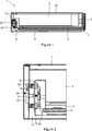
Figure 4 is a frontal view of the damper assembly shown in figure 3.
Figure 5 is a side sectional view of a representative embodiment of the damper assembly.
The elements in the figures are numbered individually and the correspondence of these numbers are given hereinafter.
1 Housing
2 Storage area
3 Drawer
4 Tray
5 Front wall
6 Functional member
8 Bearer plate
9 Rear sheet
10 Cavity
12 Back wall
20 Connector assembly
22 First connector member
24 Second connector member
25 Screw
30 Damper assembly
31 Coupling member
32 Spring member
33 Male part
331 Flange
332 Protrusion
34 Female part
341 Bore
342 Ring
35 Guide bar
36 Channel
37 Stopper cap
m1 Thrust distance
F Thrust direction
Figure 1 shows a side sectional view of a warming drawer (3) placed as built-in in a cabinet (not shown in figure), in a closed position. A housing (1) is mounted in the cabinet of an enclosed box structure. The housing (1) circumferentially delimits a cavity (10). A drawer (3) linearly skidded in the cavity (10) is extractably placed therein. The drawer (3) has a tray (4) forming a storage area (2) on its upper portion, and a front wall (5) covering the cavity (10) by enclosing the opening on the front portion of the tray (4). The front wall (5) is aligned with the housing (1) when the drawer (3) is in a closed position. In this case, the front wall (5) covers the frontal opening of the cavity (10). The front wall (5) can directly be aligned to the mouth portion of the housing (1) as well as being aligned to the outer decorative panel of the cabinet in which it is placed. A resistance which is an electrical functional member (6) is placed on the bottom of the base portion of the tray (4). The functional member (6) enables maintaining the storage area (2) at a predetermined temperature for a desired period when the drawer (3) is in closed position, and keeping the food (not shown) borne on the tray (4) warm until consumption.
On a back edge of the drawer (3), a damper assembly (30) is mounted on a proximate back wall (12) of the cavity (10). The damper assembly (30) bears a connector assembly (20). The connector assembly (20) is configured so as to maintain an electric connection to the functional member (6) when the drawer (3) is in closed position. A bearer plate (8) extending along the width of the back wall (12) of the cavity (10) so as to be spaced with the back edge of the tray (4) bears the damper assembly (30).
Figure 2 shows a blown-up view of the back portion of the housing (1) in which the drawer (3) is placed. The tray (4) has a plate structure of metal material. A rear sheet (9) is formed by bending the back edge of the tray (4). The rear sheet (9) prevents splattering of food products from the storage area (2) to the damper assembly (30) by being positioned vis-a-vis and spaced with the bearer plate (8). The damper assembly (30) is equipped with a spring member (32). The spring member (32) is a helical spring unloaded in closed position extending from the bearer plate (8) on one end to the back wall (12) on the other end. In closed position, the connector assembly (20) is in contact with the tray (4) so as transmit electricity to the functional member (6).
Figure 3 shows a perspective view of the damper assembly (30) at a thrust position, facing the back wall (12) and compressed to a thrust distance (m1), from behind. The thrust position is formed by the backwards movement of drawer (3) being in closed position and being pushed by a user on its front wall (5) into the cavity (10). A male part (33) of hat-like shape whose circumferential edges are extended so as to form a flange (331), in which a central hollow protrusion (332) is formed, engages into a female part (34) through a channel (36) formed in the middle portion of the female part (34). The female part (34) is of plate structure. A short ring (342) extending on the middle portion of the female part (34) defines the channel (36) in its inner portion. Bores (341) are opened around the ring (342) proximate to each corner of the panel. Guide bars (35) extending from corresponding portions on the male part (33) freely pass through the bores (341). Stopper caps (37) of widened end shape are arranged on the ends two mutual guide bars (35). The stopper caps (37) are obtained by mounting a screw (25) on the end of the guide bar (35). Two mutual screws (25) enable fixing a first connector member (22) of the connector assembly (20) to the male part (33) by being mounted on the protrusion (332) from their butt portions. Cables (not shown) being the electricity connection coming from the back wall (12) are connected to an operational end of the first connector member (22) facing outwards through the channel (36). Figure 4 shows a perspective view of the damper assembly (30) from its front face facing the drawer (3), in thrust position. The first connector member (22) is coupled to a corresponding second connector member of a slot structure mounted on the tray (4). The first connector member (22) extends in the center of the channel (36) in parallel with the advancement axis of the drawer (3). In thrust position, the spring members (32) are compressed between the mutual flange (331) portions of the male part (33) and the female part (34). The damper assembly (30) is mounted on the bearer plate (8) by connection members (31) extending on the female part (34).
Figure 5 shows a side view of the damper assembly (30) in closed position. Upon removal of the pressure of the drawer (3) on the bearer plate (8), the spring members (32) apply pressure in a manner separating the male part (33) and the female part (34) from each other. Thus, the male part (33) is axially aligned with the guide bars (35), moves forwards up to thrust distance (m1) and is stopped by engagement of the stopper cap (37) to the bore (341). By this, the drawer (3) can safely advance into the cavity (10) along the thrust distance (m1) without colliding with the connector assembly (20) in the cavity (10). This allows adapting in particular a push-push mechanism (not shown) to the drawer (3). The housing (1) is mounted in a cabinet (5) so as to be aligned with decorative plates. The first connector member (22) and the second connector member (24) are coupled to each other when the drawer (3) is in closed position. The drawer (3) is pushed inwards up to thrust distance (m1) by applying a force on its front wall (5) in thrust direction (F). Meanwhile, upon the male part (33) being pushed by the back edge of the tray (4), the spring member (32) in unloaded state is compressed towards the female part (34). Thus, the spring member (32) generates a contrasting force in thrust direction (F). Thrust position is reached through covering the entire thrust distance (m1) by overcoming the contrasting force. In this case, the connector assembly (20) is protected inside the channel (36) when the male part (33) passes through the female part (34). The push-push mechanism rapidly pushes the drawer (3) outwards upon removal of the force. In this case, the male part (33) gets out of the female part (34) up to thrust distance (m1) by means of the compression force of the spring member (32) and stops by taking its initial position. In turn, the tray (4) takes the open position from which loading can be performed, thanks to the push-push mechanism.
Claims (8)
- A household appliance comprising in a cavity (10) of a housing (1) a movable drawer (3) having a tray (4) whose storage area (2) is accessible in an open position, and a front wall (5) provided on the front portion of the tray (4), aligning with the housing (1) in a closed position, characterized in that, a damper assembly(30) is fixed in the cavity (10) in such a manner that it supports the tray (4) so as to allow advancement to a delimited thrust distance (m1) to which the tray (4) enters the cavity (10) when pressure is applied on the front wall (5) and pushes the tray (4) back to closed position when released.
- The household appliance according to claim 1, wherein the damper assembly (30) is fixed on a back wall (12) of the cavity (10) so as to face the tray (4).
- The household appliance according to any one of the preceding claims, wherein the damper assembly (30) comprises a male part (33) extending in parallel with the advancement axis of the tray (4), and a female part (34) through which the male part (33) is extended for at least the thrust distance (m1).
- The household appliance according to claim 3, wherein it comprises a spring member (32) adjusted to apply pressure to the male part (33) and the female part (34) between them in the direction of the thrust distance (m1).
- The household appliance according to claim 3 or 4, wherein it comprises a channel (36) passing through the male part (33) and female part (34) and a connector assembly (20) placed in said channel (36).
- The household appliance according to claim 5, wherein the male part (33) and the female part (34) are co-axial with the channel (36).
- The household appliance according to claim 5, wherein the connector assembly (20) comprises a first connector member (22) fixed to the male part (33) so as to face the tray (4), and a second connector member (24) placed on the tray (4) coupled so as to transmit electricity to the first connector member (22) when the drawer (3) takes a closed position.
- The household appliance according to any one of the preceding claims, wherein the tray (4) comprises a rear sheet (9) fixed to its back edge, and bent so as to leave a distance greater than the thrust distance (m1) with the back wall (12) of the cavity (10) in closed position.
Applications Claiming Priority (2)
| Application Number | Priority Date | Filing Date | Title |
|---|---|---|---|
| TR201611003 | 2016-08-05 | ||
| TRA2016/11003 | 2016-08-05 |
Publications (1)
| Publication Number | Publication Date |
|---|---|
| WO2018024804A1 true WO2018024804A1 (en) | 2018-02-08 |
Family
ID=59581900
Family Applications (1)
| Application Number | Title | Priority Date | Filing Date |
|---|---|---|---|
| PCT/EP2017/069594 WO2018024804A1 (en) | 2016-08-05 | 2017-08-03 | A household appliance having a movable drawer |
Country Status (1)
| Country | Link |
|---|---|
| WO (1) | WO2018024804A1 (en) |
Citations (3)
| Publication number | Priority date | Publication date | Assignee | Title |
|---|---|---|---|---|
| GB511445A (en) * | 1938-02-17 | 1939-08-18 | Richard Hawke Rogers | Improvements in and connected with electric cooking apparatus |
| EP1806538A2 (en) | 2006-01-08 | 2007-07-11 | Whirlpool Corporation | Warming drawer |
| JP2011089738A (en) * | 2009-10-26 | 2011-05-06 | Panasonic Corp | Heating cooker |
-
2017
- 2017-08-03 WO PCT/EP2017/069594 patent/WO2018024804A1/en active Application Filing
Patent Citations (3)
| Publication number | Priority date | Publication date | Assignee | Title |
|---|---|---|---|---|
| GB511445A (en) * | 1938-02-17 | 1939-08-18 | Richard Hawke Rogers | Improvements in and connected with electric cooking apparatus |
| EP1806538A2 (en) | 2006-01-08 | 2007-07-11 | Whirlpool Corporation | Warming drawer |
| JP2011089738A (en) * | 2009-10-26 | 2011-05-06 | Panasonic Corp | Heating cooker |
Similar Documents
| Publication | Publication Date | Title |
|---|---|---|
| US9677807B2 (en) | Refrigerator | |
| EP2716977B1 (en) | Cooking oven | |
| CN103562478B (en) | The door lock assembly of electric household appliance | |
| US8656828B2 (en) | Electric oven for cooking food | |
| KR100306558B1 (en) | Heating Cooker | |
| US20200088415A1 (en) | Cooking appliance | |
| US11519609B2 (en) | Cooking appliance | |
| US20170058567A1 (en) | Locking device for a door of a domestic appliance | |
| CN107076425A (en) | Operate the home appliances of the method, related food printer and correlation of food printer | |
| US20140231421A1 (en) | Cooker | |
| WO2018024804A1 (en) | A household appliance having a movable drawer | |
| EP3149408B1 (en) | Oven | |
| KR101695410B1 (en) | Cauldron type induction cooker using electromagnetic induction device | |
| JP3854959B2 (en) | Electric oven and microwave oven with heater | |
| US6723962B1 (en) | Double deck toaster oven | |
| US10641500B2 (en) | Shelf supporting apparatus and cooking appliance including a shelf supporting apparatus | |
| KR102030472B1 (en) | Apparatus for fixing electric wires of electric rice cooker | |
| CN220192796U (en) | Wire body mounting structure and kitchen appliance | |
| CN214484230U (en) | Pressure switch and electric pressure cooker | |
| CN211321541U (en) | Microwave heating device with explosion-proof function | |
| CN208822471U (en) | Baking machine | |
| US20190239295A1 (en) | Cooking appliance | |
| CN106504944A (en) | Delayed management current sensitive thermal protector | |
| CN107550240B (en) | Double-layer heat-insulation and heat-preservation furnace core of electric cooker and electric cooker | |
| EP3507550B1 (en) | A cooler comprising a gasket disengagement mechanism |
Legal Events
| Date | Code | Title | Description |
|---|---|---|---|
| 121 | Ep: the epo has been informed by wipo that ep was designated in this application |
Ref document number: 17751345 Country of ref document: EP Kind code of ref document: A1 |
|
| NENP | Non-entry into the national phase |
Ref country code: DE |
|
| 122 | Ep: pct application non-entry in european phase |
Ref document number: 17751345 Country of ref document: EP Kind code of ref document: A1 |