WO2018020841A1 - Voice monitoring system and voice monitoring method - Google Patents
Voice monitoring system and voice monitoring method Download PDFInfo
- Publication number
- WO2018020841A1 WO2018020841A1 PCT/JP2017/020900 JP2017020900W WO2018020841A1 WO 2018020841 A1 WO2018020841 A1 WO 2018020841A1 JP 2017020900 W JP2017020900 W JP 2017020900W WO 2018020841 A1 WO2018020841 A1 WO 2018020841A1
- Authority
- WO
- WIPO (PCT)
- Prior art keywords
- sound
- monitoring system
- unit
- time
- sound parameter
- Prior art date
Links
- 238000012544 monitoring process Methods 0.000 title claims description 136
- 238000000034 method Methods 0.000 title claims description 46
- 238000004364 calculation method Methods 0.000 claims abstract description 86
- 238000003384 imaging method Methods 0.000 claims abstract description 20
- 230000001186 cumulative effect Effects 0.000 claims abstract description 19
- 230000000007 visual effect Effects 0.000 claims description 86
- 238000001514 detection method Methods 0.000 claims description 64
- 238000004458 analytical method Methods 0.000 claims description 46
- 230000007717 exclusion Effects 0.000 claims description 12
- 238000012545 processing Methods 0.000 description 39
- 238000010586 diagram Methods 0.000 description 37
- 238000006243 chemical reaction Methods 0.000 description 22
- 239000002131 composite material Substances 0.000 description 10
- 238000004891 communication Methods 0.000 description 6
- 238000012800 visualization Methods 0.000 description 6
- 101100079986 Caenorhabditis elegans nrfl-1 gene Proteins 0.000 description 5
- 230000006835 compression Effects 0.000 description 5
- 238000007906 compression Methods 0.000 description 5
- 238000012935 Averaging Methods 0.000 description 4
- 238000004040 coloring Methods 0.000 description 4
- 230000005540 biological transmission Effects 0.000 description 3
- 239000000284 extract Substances 0.000 description 3
- 238000009434 installation Methods 0.000 description 3
- 238000010606 normalization Methods 0.000 description 3
- NAWXUBYGYWOOIX-SFHVURJKSA-N (2s)-2-[[4-[2-(2,4-diaminoquinazolin-6-yl)ethyl]benzoyl]amino]-4-methylidenepentanedioic acid Chemical compound C1=CC2=NC(N)=NC(N)=C2C=C1CCC1=CC=C(C(=O)N[C@@H](CC(=C)C(O)=O)C(O)=O)C=C1 NAWXUBYGYWOOIX-SFHVURJKSA-N 0.000 description 2
- 230000000593 degrading effect Effects 0.000 description 2
- 230000005236 sound signal Effects 0.000 description 2
- 238000007794 visualization technique Methods 0.000 description 2
- 206010002953 Aphonia Diseases 0.000 description 1
- 238000009825 accumulation Methods 0.000 description 1
- 230000006399 behavior Effects 0.000 description 1
- 230000000295 complement effect Effects 0.000 description 1
- 238000012790 confirmation Methods 0.000 description 1
- 239000000470 constituent Substances 0.000 description 1
- 230000000694 effects Effects 0.000 description 1
- 238000005516 engineering process Methods 0.000 description 1
- 230000014509 gene expression Effects 0.000 description 1
- 238000010191 image analysis Methods 0.000 description 1
- 230000007774 longterm Effects 0.000 description 1
- 229910044991 metal oxide Inorganic materials 0.000 description 1
- 150000004706 metal oxides Chemical class 0.000 description 1
- 238000012986 modification Methods 0.000 description 1
- 230000004048 modification Effects 0.000 description 1
- 230000004044 response Effects 0.000 description 1
- 239000004065 semiconductor Substances 0.000 description 1
Images


Classifications
-
- H—ELECTRICITY
- H04—ELECTRIC COMMUNICATION TECHNIQUE
- H04N—PICTORIAL COMMUNICATION, e.g. TELEVISION
- H04N7/00—Television systems
- H04N7/18—Closed-circuit television [CCTV] systems, i.e. systems in which the video signal is not broadcast
-
- G—PHYSICS
- G10—MUSICAL INSTRUMENTS; ACOUSTICS
- G10L—SPEECH ANALYSIS TECHNIQUES OR SPEECH SYNTHESIS; SPEECH RECOGNITION; SPEECH OR VOICE PROCESSING TECHNIQUES; SPEECH OR AUDIO CODING OR DECODING
- G10L21/00—Speech or voice signal processing techniques to produce another audible or non-audible signal, e.g. visual or tactile, in order to modify its quality or its intelligibility
-
- G—PHYSICS
- G06—COMPUTING; CALCULATING OR COUNTING
- G06Q—INFORMATION AND COMMUNICATION TECHNOLOGY [ICT] SPECIALLY ADAPTED FOR ADMINISTRATIVE, COMMERCIAL, FINANCIAL, MANAGERIAL OR SUPERVISORY PURPOSES; SYSTEMS OR METHODS SPECIALLY ADAPTED FOR ADMINISTRATIVE, COMMERCIAL, FINANCIAL, MANAGERIAL OR SUPERVISORY PURPOSES, NOT OTHERWISE PROVIDED FOR
- G06Q50/00—Information and communication technology [ICT] specially adapted for implementation of business processes of specific business sectors, e.g. utilities or tourism
- G06Q50/10—Services
-
- G—PHYSICS
- G10—MUSICAL INSTRUMENTS; ACOUSTICS
- G10L—SPEECH ANALYSIS TECHNIQUES OR SPEECH SYNTHESIS; SPEECH RECOGNITION; SPEECH OR VOICE PROCESSING TECHNIQUES; SPEECH OR AUDIO CODING OR DECODING
- G10L17/00—Speaker identification or verification techniques
- G10L17/06—Decision making techniques; Pattern matching strategies
- G10L17/14—Use of phonemic categorisation or speech recognition prior to speaker recognition or verification
-
- G—PHYSICS
- G10—MUSICAL INSTRUMENTS; ACOUSTICS
- G10L—SPEECH ANALYSIS TECHNIQUES OR SPEECH SYNTHESIS; SPEECH RECOGNITION; SPEECH OR VOICE PROCESSING TECHNIQUES; SPEECH OR AUDIO CODING OR DECODING
- G10L25/00—Speech or voice analysis techniques not restricted to a single one of groups G10L15/00 - G10L21/00
- G10L25/48—Speech or voice analysis techniques not restricted to a single one of groups G10L15/00 - G10L21/00 specially adapted for particular use
- G10L25/51—Speech or voice analysis techniques not restricted to a single one of groups G10L15/00 - G10L21/00 specially adapted for particular use for comparison or discrimination
- G10L25/60—Speech or voice analysis techniques not restricted to a single one of groups G10L15/00 - G10L21/00 specially adapted for particular use for comparison or discrimination for measuring the quality of voice signals
-
- G—PHYSICS
- G10—MUSICAL INSTRUMENTS; ACOUSTICS
- G10L—SPEECH ANALYSIS TECHNIQUES OR SPEECH SYNTHESIS; SPEECH RECOGNITION; SPEECH OR VOICE PROCESSING TECHNIQUES; SPEECH OR AUDIO CODING OR DECODING
- G10L25/00—Speech or voice analysis techniques not restricted to a single one of groups G10L15/00 - G10L21/00
- G10L25/78—Detection of presence or absence of voice signals
- G10L25/84—Detection of presence or absence of voice signals for discriminating voice from noise
-
- H—ELECTRICITY
- H04—ELECTRIC COMMUNICATION TECHNIQUE
- H04N—PICTORIAL COMMUNICATION, e.g. TELEVISION
- H04N7/00—Television systems
- H04N7/18—Closed-circuit television [CCTV] systems, i.e. systems in which the video signal is not broadcast
- H04N7/183—Closed-circuit television [CCTV] systems, i.e. systems in which the video signal is not broadcast for receiving images from a single remote source
-
- H—ELECTRICITY
- H04—ELECTRIC COMMUNICATION TECHNIQUE
- H04R—LOUDSPEAKERS, MICROPHONES, GRAMOPHONE PICK-UPS OR LIKE ACOUSTIC ELECTROMECHANICAL TRANSDUCERS; DEAF-AID SETS; PUBLIC ADDRESS SYSTEMS
- H04R1/00—Details of transducers, loudspeakers or microphones
- H04R1/20—Arrangements for obtaining desired frequency or directional characteristics
- H04R1/32—Arrangements for obtaining desired frequency or directional characteristics for obtaining desired directional characteristic only
- H04R1/40—Arrangements for obtaining desired frequency or directional characteristics for obtaining desired directional characteristic only by combining a number of identical transducers
- H04R1/406—Arrangements for obtaining desired frequency or directional characteristics for obtaining desired directional characteristic only by combining a number of identical transducers microphones
-
- H—ELECTRICITY
- H04—ELECTRIC COMMUNICATION TECHNIQUE
- H04R—LOUDSPEAKERS, MICROPHONES, GRAMOPHONE PICK-UPS OR LIKE ACOUSTIC ELECTROMECHANICAL TRANSDUCERS; DEAF-AID SETS; PUBLIC ADDRESS SYSTEMS
- H04R3/00—Circuits for transducers, loudspeakers or microphones
-
- H—ELECTRICITY
- H04—ELECTRIC COMMUNICATION TECHNIQUE
- H04S—STEREOPHONIC SYSTEMS
- H04S7/00—Indicating arrangements; Control arrangements, e.g. balance control
- H04S7/40—Visual indication of stereophonic sound image
-
- G—PHYSICS
- G10—MUSICAL INSTRUMENTS; ACOUSTICS
- G10L—SPEECH ANALYSIS TECHNIQUES OR SPEECH SYNTHESIS; SPEECH RECOGNITION; SPEECH OR VOICE PROCESSING TECHNIQUES; SPEECH OR AUDIO CODING OR DECODING
- G10L21/00—Speech or voice signal processing techniques to produce another audible or non-audible signal, e.g. visual or tactile, in order to modify its quality or its intelligibility
- G10L21/06—Transformation of speech into a non-audible representation, e.g. speech visualisation or speech processing for tactile aids
-
- G—PHYSICS
- G10—MUSICAL INSTRUMENTS; ACOUSTICS
- G10L—SPEECH ANALYSIS TECHNIQUES OR SPEECH SYNTHESIS; SPEECH RECOGNITION; SPEECH OR VOICE PROCESSING TECHNIQUES; SPEECH OR AUDIO CODING OR DECODING
- G10L25/00—Speech or voice analysis techniques not restricted to a single one of groups G10L15/00 - G10L21/00
- G10L25/03—Speech or voice analysis techniques not restricted to a single one of groups G10L15/00 - G10L21/00 characterised by the type of extracted parameters
- G10L25/21—Speech or voice analysis techniques not restricted to a single one of groups G10L15/00 - G10L21/00 characterised by the type of extracted parameters the extracted parameters being power information
-
- G—PHYSICS
- G10—MUSICAL INSTRUMENTS; ACOUSTICS
- G10L—SPEECH ANALYSIS TECHNIQUES OR SPEECH SYNTHESIS; SPEECH RECOGNITION; SPEECH OR VOICE PROCESSING TECHNIQUES; SPEECH OR AUDIO CODING OR DECODING
- G10L25/00—Speech or voice analysis techniques not restricted to a single one of groups G10L15/00 - G10L21/00
- G10L25/48—Speech or voice analysis techniques not restricted to a single one of groups G10L15/00 - G10L21/00 specially adapted for particular use
- G10L25/51—Speech or voice analysis techniques not restricted to a single one of groups G10L15/00 - G10L21/00 specially adapted for particular use for comparison or discrimination
- G10L25/57—Speech or voice analysis techniques not restricted to a single one of groups G10L15/00 - G10L21/00 specially adapted for particular use for comparison or discrimination for processing of video signals
-
- G—PHYSICS
- G10—MUSICAL INSTRUMENTS; ACOUSTICS
- G10L—SPEECH ANALYSIS TECHNIQUES OR SPEECH SYNTHESIS; SPEECH RECOGNITION; SPEECH OR VOICE PROCESSING TECHNIQUES; SPEECH OR AUDIO CODING OR DECODING
- G10L25/00—Speech or voice analysis techniques not restricted to a single one of groups G10L15/00 - G10L21/00
- G10L25/78—Detection of presence or absence of voice signals
-
- H—ELECTRICITY
- H04—ELECTRIC COMMUNICATION TECHNIQUE
- H04R—LOUDSPEAKERS, MICROPHONES, GRAMOPHONE PICK-UPS OR LIKE ACOUSTIC ELECTROMECHANICAL TRANSDUCERS; DEAF-AID SETS; PUBLIC ADDRESS SYSTEMS
- H04R2430/00—Signal processing covered by H04R, not provided for in its groups
- H04R2430/20—Processing of the output signals of the acoustic transducers of an array for obtaining a desired directivity characteristic
-
- H—ELECTRICITY
- H04—ELECTRIC COMMUNICATION TECHNIQUE
- H04R—LOUDSPEAKERS, MICROPHONES, GRAMOPHONE PICK-UPS OR LIKE ACOUSTIC ELECTROMECHANICAL TRANSDUCERS; DEAF-AID SETS; PUBLIC ADDRESS SYSTEMS
- H04R27/00—Public address systems
-
- H—ELECTRICITY
- H04—ELECTRIC COMMUNICATION TECHNIQUE
- H04R—LOUDSPEAKERS, MICROPHONES, GRAMOPHONE PICK-UPS OR LIKE ACOUSTIC ELECTROMECHANICAL TRANSDUCERS; DEAF-AID SETS; PUBLIC ADDRESS SYSTEMS
- H04R3/00—Circuits for transducers, loudspeakers or microphones
- H04R3/005—Circuits for transducers, loudspeakers or microphones for combining the signals of two or more microphones
Definitions
- the present disclosure relates to a voice monitoring system and a voice monitoring method for analyzing a flow line of a person in a monitoring target area.
- a flow line visualization technique using a person detection and person tracking technique by image analysis is known.
- this visualization technology it is possible to analyze the location of a person's movement, but for example, how much time, at what location in a store, such as a restaurant or a convenience store where customer service is frequently performed, the conversation between the store clerk and the store visitor It is not possible to distinguish whether or not a visitor is just taking place.
- Patent Document 1 an image processing apparatus disclosed in Patent Document 1 has been proposed as a prior art related to the flow line visualization technique described above.
- This image processing apparatus processes the image captured by the camera to detect the face of the meeting attendee, detects the arrival direction of the sound by a plurality of microphones, and determines the direction in which the sound is collected based on the deviation time information. Change and calculate the collected sound level. Further, the image processing apparatus displays an image indicating the audio level on the head of the speaker of the conference attendee in the conference room image based on the face detection information, the voice arrival direction information, and the audio level information.
- This disclosure analyzes how long a person has been serving customers at a certain level in the past specified period of time, such as a store, and at what audio level, and the analysis results.
- the purpose is to improve the accuracy of monitoring analysis.
- the voice monitoring system includes a camera that captures an area to be monitored, a microphone array that collects sound of the area, a captured image captured by the camera, a capturing time, and sound that is captured by the microphone array.
- a sound parameter indicating the loudness of the area at the time of image capturing based on the sound collected by the microphone array during image capturing by the camera and a recorder that records sound in association with sound;
- a sound parameter calculation unit that repeatedly calculates for each predetermined unit of the constituent pixels, and a sound parameter that stores the sound parameter calculated by the sound parameter calculation unit in association with position information on the captured image at the imaging time
- a sound source visual image based on the storage unit and the sound parameter is superimposed for each predetermined unit of pixels constituting the captured image.
- a sound parameter display control unit for displaying on a monitor, and the sound parameter display control unit converts the sound parameter stored in the sound parameter storage unit to a cumulative value in the time range according to designation of the time range.
- the sound source visual image based on is superimposed on every predetermined unit of pixels constituting the captured image and displayed on the monitor.
- the imaging system includes the image processing device, the plurality of cameras, and the display input device.
- the audio monitoring method of the present disclosure is an audio monitoring method in an audio monitoring system including a camera, a microphone array, a recorder, and a playback control device, wherein the camera images an area to be monitored,
- the microphone array picks up the sound of the area
- the recorder records the picked-up image and pick-up time picked up by the camera in association with the sound picked up by the microphone array
- the playback control device Is based on the sound picked up by the microphone array during imaging by the camera, and repeats a sound parameter indicating the loudness of the area at the imaging time for each predetermined unit of the pixels constituting the captured image.
- the reproduction control apparatus compares the calculated sound parameter with position information on the captured image at the imaging time.
- the reproduction control device monitors the sound source visual image based on the sound parameter by superimposing it on a predetermined unit basis of pixels constituting the picked-up image, and the reproduction control device The sound source visual image based on the cumulative value in the time range of the sound parameter stored in the recorder is superimposed for each predetermined unit of pixels constituting the captured image in accordance with the specification of the time range. Display on the monitor.
- a monitoring target area such as a store
- an analysis is made of how long a person has been serving a customer at what audio level during a specified past certain period, The analysis result can be shown visually and the monitoring analysis accuracy can be improved.
- FIG. 1 is a diagram illustrating an installation example of a voice monitoring system according to the first embodiment in a store.
- FIG. 2 is a block diagram showing in detail an example of the system configuration of the voice monitoring system according to the first embodiment.
- FIG. 3 is a block diagram showing in detail an example of the internal configuration of the microphone array.
- FIG. 4 is a block diagram showing in detail an example of the internal configuration of the omnidirectional camera.
- FIG. 5 is a diagram illustrating an example of a GUI displayed on the monitor.
- FIG. 6 is a flowchart for explaining in detail an example of each operation procedure of calculation and storage of sound parameters in the recorder of the first embodiment.
- FIG. 7 is a diagram illustrating an example of calculating sound parameters.
- FIG. 1 is a diagram illustrating an installation example of a voice monitoring system according to the first embodiment in a store.
- FIG. 2 is a block diagram showing in detail an example of the system configuration of the voice monitoring system according to the first embodiment.
- FIG. 3 is a
- FIG. 8 is a diagram illustrating an example of the structure of a file in which sound parameters according to the first embodiment are stored.
- FIG. 9 is a flowchart for explaining in detail an example of an operation procedure of sound parameter display according to the first embodiment.
- FIG. 10 is a diagram illustrating an example of the GUI at time t2 displayed on the monitor.
- FIG. 11 is a flowchart illustrating in detail an example of an operation procedure for converting RGB values according to the third embodiment.
- FIG. 12 is a diagram illustrating an example of a GUI displayed on the monitor according to the fifth embodiment.
- FIG. 13 is a diagram illustrating a structure example of a file storing sound parameters in units of 60 seconds according to the sixth embodiment.
- FIG. 14 is a flowchart illustrating in detail an example of an operation procedure for displaying sound parameters according to the eighth embodiment.
- FIG. 15 is a diagram illustrating an example of a GUI displayed on the monitor according to the ninth embodiment.
- FIG. 16 is a diagram illustrating an example of a loud region detected in the monitoring area of the tenth embodiment.
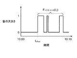
- FIG. 17A is a graph showing the time change (presence / absence of voice) of voice detection in the coordinates (Ux, Uy) of the designated area FR in the designated time range (10:00 to 10:30).
- FIG. 17B is a diagram showing an example of a sound reproduction list in the sound detection period detected in FIG. 17A.
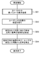
- FIG. 18 is a flowchart illustrating in detail an example of each operation procedure of speech enhancement processing and reproduction according to the tenth embodiment.
- FIG. 19 is a flowchart for explaining in detail an example of each operation procedure of speech enhancement processing and reproduction according to the eleventh embodiment.
- FIG. 20 is a diagram illustrating an example of coordinates (Ux, Uy) of the designated area selected by the user from the monitoring area.
- FIG. 21 is a graph showing an example of the time change of voice detection at the coordinates (Ux, Uy) of the designated area.
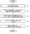
- FIG. 22 is a flowchart for explaining in detail an example of each operation procedure of speech enhancement processing and reproduction according to the twelfth embodiment.
- FIG. 20 is a diagram illustrating an example of coordinates (Ux, Uy) of the designated area selected by the user from the monitoring area.
- FIG. 21 is a graph showing an example of the time change of voice detection at the coordinates (Ux, Uy) of the designated area.
- FIG. 22 is a
- FIG. 23 is a flowchart illustrating in detail an example of an operation procedure for displaying sound parameters according to the thirteenth embodiment.
- FIG. 24 is a block diagram illustrating in detail an example of the system configuration of the voice monitoring system according to the fourteenth embodiment.
- FIG. 25 is a diagram illustrating an example of a part of a GUI displayed on the monitor according to the fourteenth embodiment.
- FIG. 26 is a diagram illustrating a display example in which a sound source visual image (audio heat map MP) is superimposed on a captured image at a display start time in a time range specified by a user operation.
- FIG. 27 is a diagram illustrating a display example in which a sound source visual image (sound heat map MP) and utterance contents of a plurality of people are superimposed on a captured image at a search time designated by a user operation.
- FIG. 28 is a flowchart illustrating in detail an example of an operation procedure for displaying sound parameters according to the fourteenth embodiment.
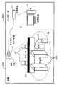
- FIG. 1 is a diagram illustrating an installation example of a voice monitoring system 5 according to the first embodiment in a store.
- the voice monitoring system 5 is installed in a store 200 such as a restaurant or a convenience store, for example, and monitors the customer service status of a target (for example, a store clerk) monitored by a monitor such as a store manager.
- a target for example, a store clerk
- the voice monitoring system 5 is described as being installed in a store.
- the installation destination is not limited to a store, and may be installed in a public facility such as a factory or a library, or in an office.
- a product shelf 201 on which many products are displayed, a counter 202, and the like are installed.
- the counter 202 is used to check out products purchased by customers, and is, for example, a cashier counter.
- the store clerk p1 and the customer p2 usually face each other across the counter 202 and have a conversation.
- the voice monitoring system 5 includes a microphone array camera device 10, a browsing device 30, and a recording device 70.
- the microphone array / camera apparatus 10 is configured by integrally combining a microphone array MA and an omnidirectional camera CA in a coaxial direction, and is fixedly mounted above the counter 202.
- the microphone array camera device 10 is attached to the ceiling of the store 200.
- the omnidirectional camera CA images the monitoring area SA including the counter 202.
- the monitoring area is an area to be monitored by the voice monitoring system 5 for the situation of customer service, etc., and so on.
- the microphone array MA collects sound emitted from the area covering the monitoring area SA.
- the browsing device 30 is arranged in the backyard 200z of the store 200, displays an image (captured image) captured by the omnidirectional camera CA so that it can be browsed, and further, the speaker 50 ( (See FIG. 2).
- the recording device 70 as a recorder is arranged in the backyard 200z of the store 200, as with the browsing device 30, and is picked up by an image (captured image) and imaged time taken by the omnidirectional camera CA, and by the microphone array MA. Sounds and sound collection times are recorded in association with each other. Further, the recording device 70 repeatedly stores sound parameters (see later) calculated at regular intervals.
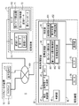
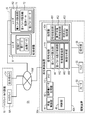
- FIG. 2 is a block diagram showing in detail an example of the system configuration of the voice monitoring system 5 of the first embodiment.
- the microphone array / camera device 10, the browsing device 30, and the recording device 70 are connected to each other via a network NW so that data communication can be performed.
- the network NW may be a wired network (for example, an intranet or the Internet) or a wireless network (for example, a wireless LAN (Local Area Network)).
- the recording device 70 records various data and includes a recorder R1 and a recorder R2.
- the recorder R1 records the sound data and sound collection time collected by the microphone array MA in association with the data and the image capture time of the captured image captured by the omnidirectional camera CA.
- the sound collection time may be a time of time information included in sound data transmitted from the microphone array MA, or may be a time when sound data transmitted from the microphone array MA is received by the recorder R1.
- the imaging time may be the time of time information included in the captured image data transmitted from the omnidirectional camera CA, or when the captured image data transmitted from the omnidirectional camera CA is received by the recorder R1.
- the recorder R2 has a sound parameter calculation unit 71 and a sound parameter storage unit 72.
- the sound parameter calculation unit 71 calculates a sound parameter based on the sound data recorded in the recorder R1 or the sound data collected by the microphone array MA.
- the sound parameter is a parameter indicating the volume of sound collected by the microphone array MA, for example, sound pressure.
- the sound parameter is not limited to sound pressure, but may be a volume level, or simply the presence or absence of sound, or an amount obtained by multiplying sound pressure and sound detection time.
- the details of the sound parameter calculation process of the sound parameter calculation unit 71 are the same as the sound parameter calculation process of the sound parameter calculation unit 441 described later, and thus the description thereof is omitted here.
- the sound parameter storage unit 72 stores the sound parameter calculated by the sound parameter calculation unit 71 in association with the time information at the time of calculation.
- the recorder R1 and the recorder R2 are configured as separate devices in the recording device 70, but may be configured such that the recorder R1 and the recorder R2 are integrated.
- the recorder R2 may further record recording data (that is, image data and imaging time data, sound data and sound collection time data) recorded in the recorder R1. Good.
- the browsing device 30 includes a playback control device 40, a speaker 50, a monitor 55, and an operation unit 58.
- the reproduction control device 40 displays the data of the picked-up image picked up by the omnidirectional camera CA on the monitor 55 and reproduces the sound data picked up by the microphone array MA from the speaker 50.
- the reproduction control device 40 includes a reproduction control unit 41, a directional sound data generation unit 42, a memory 43, a signal processing unit 44, a designation unit 45, and a determination unit 46.
- the reproduction control unit 41 uses the sound data and image data recorded in the recorder R1 to perform the sound within the corresponding time range. Data and image data are acquired, sound data is output as sound through the speaker 50, and the image data is further displayed on the monitor 55.
- the reproduction control unit 41 is designated to the directional sound data generation unit 42 described later when the monitor performs a designation operation for a certain time range and a designation operation for a position on the captured image displayed on the monitor 55.
- the sound data in the specified time range is instructed to be emphasized.
- the reproduction control unit 41 reproduces the emphasized sound data output from the directional sound data generation unit 42 by outputting the sound through the speaker 50.
- the directional sound data generating unit 42 as the directional sound emphasizing unit uses, for example, sound data recorded in the recorder R1 in response to an instruction from the reproduction control unit 41, from the microphone array MA, for example, by a supervisor such as a store manager.
- the sound in the direction toward the sound source position corresponding to the position on the captured image designated by the operation is emphasized as the directivity direction.
- the directional sound data generation unit 42 generates sound data in which sound in the directional direction is emphasized by forming sound directivity with respect to the directional direction.
- the memory 43 is configured by using, for example, a RAM (Random Access Memory) or an HDD (Hard Disk Drive), and various types such as a sound parameter calculated by the sound parameter calculation unit 441 and a time accumulated value F of the sound parameter for a certain period. Information (see later) is stored. Further, the memory 43 stores various information such as a recording date and time, a display time unit, coordinates of a designated area, a reproduction list, and the like displayed on a GUI 100 (see FIG. 5) described later.
- a RAM Random Access Memory
- HDD Hard Disk Drive
- the signal processing unit 44 converts the captured image distributed from the omnidirectional camera CA (that is, the image constituting the current live video) or the captured image recorded on the recorder R1 (that is, the image constituting the past recorded video). A sound source visual image to be superimposed (see later) is generated.
- the signal processing unit 44 includes at least a sound parameter calculation unit 441, a sound parameter display control unit 442, and a color information conversion unit 443.
- the sound parameter calculation unit 441 uses the image data of the captured image captured by the omnidirectional camera CA and the sound data of the sound collected by the microphone array MA for each pixel constituting the image data. Sound parameters (for example, sound pressure) are calculated.
- the sound parameter calculation unit 441 has directivity (in the direction from the microphone array MA toward the position of the monitoring area SA corresponding to the pixel to be calculated).
- the sound pressure is calculated by determining the presence or absence of sound after emphasizing the sound in that direction.
- the sound parameter calculation unit 441 generates a sound pressure map in which a calculated value of sound pressure is assigned to the position of the corresponding pixel for each pixel constituting the image data.
- a sound pressure map may be generated by assigning a value.
- the sound parameter display control unit 442 is a captured image distributed from the omnidirectional camera CA (that is, an image constituting a current live video) or a captured image recorded on the recorder R1 (that is, an image constituting a past recorded video). Display control for superimposing a sound source visual image on the sound source). Details of the operation of the sound parameter display control unit 442 will be described later.
- the color information conversion unit 443 calculates RGB values based on the sound parameters calculated by the sound parameter calculation unit 441, and generates a sound source visual image corresponding to the RGB values.
- the sound source visual image generation process corresponding to the color information (RGB values) by the color information conversion unit 443 will be described later.
- the designation unit 45 includes an area designation unit 451 and a display target date / time designation unit 452.
- the area designating unit 451 designates a designated area FR (see FIG. 5), which is an area where the user wants to hear the voice, by a user operation.
- the display target date / time specifying unit 452 specifies the date / time at which the user wants to listen to the sound by a user operation. The date and time that the user wants to hear is determined by using the recording date and time selection unit 104, the display time unit setting unit 105, and the display target range setting unit 106 on the GUI 100 (see FIG. 5). It is specified by instructing.
- the determination unit 46 determines whether or not the time range specified in the display target range setting unit 106 by the user operation is smaller than the storage interval AA1 as the first interval of the voice parameter already recorded in the recorder R2.
- the determination unit 46 is used in an eighth embodiment to be described later, and details of the operation of the determination unit 46 will be described later.
- the speaker 50 outputs sound data of sound collected in real time by the microphone array MA or sound data recorded in the recorder R1.
- the monitor 55 displays a graphical user interface (GUI) 100 (see FIG. 5). Details of the GUI 100 will be described later.
- GUI graphical user interface
- the operation unit 58 receives an operation instruction from the user with respect to the GUI 100, and may be a touch panel integrated with the monitor 55 in addition to an input device such as a mouse and a keyboard.
- Examples of operation instructions from the user include designation of a video / audio file, designation of a position of a designated area, designation of a time range of sound to be displayed, and instruction to start reproduction.
- FIG. 3 is a block diagram showing an example of the internal configuration of the microphone array MA in detail.
- a plurality of A / D converters A1 to An for converting analog signals output from the digital signals into digital signals, a compression processing unit 25, and a transmission unit 26, respectively.
- the compression processor 25 generates audio data packets based on the digital audio signals output from the A / D converters A1 to An.
- the transmission unit 26 transmits the audio data packet generated by the compression processing unit 25 to the browsing device 30 or the recording device 70 via the network NW.
- the microphone array MA amplifies the output signals of the microphones M1 to Mn with the amplifiers PA1 to PAn, converts them into digital audio signals with the A / D converters A1 to An, and then compresses the audio data with the compression processing unit 25. Generate a packet.
- the microphone array MA transmits the audio data packet to the browsing device 30 or the recording device 70 via the network NW.
- FIG. 4 is a block diagram showing in detail an example of the internal configuration of the omnidirectional camera CA.
- the omnidirectional camera CA includes a CPU 61, a communication unit 62, a power management unit 64, an image sensor 65, a memory 66, and a network connector 67.
- the CPU 61 comprehensively controls each unit of the omnidirectional camera CA.
- the image sensor 65 captures the monitoring area SA and acquires image data, and is constituted by a CMOS (complementary metal oxide semiconductor) sensor.
- CMOS complementary metal oxide semiconductor
- a CCD (charge coupled device) sensor may be used instead of the CMOS sensor.
- the memory 66 includes a ROM 66z that stores operation programs and setting value data, a RAM 66y that stores image data and work data, and a memory card 66x that is detachably connected to the omnidirectional camera CA and stores various data. .
- the communication unit 62 is a network interface (I / F) that controls data communication with the network NW connected via the network connector 67.
- the power management unit 64 supplies DC power to each unit of the omnidirectional camera CA, and supplies DC power to devices connected to the network NW via the network connector 67.
- the network connector 67 is a connector that can transmit communication data such as image data and can supply power via a network cable.
- an omnidirectional camera is used, but instead of an omnidirectional camera, a pan / tilt / zoomable PTZ camera or a fixed point camera with a fixed angle of view may be used.
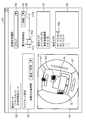
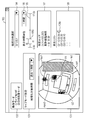
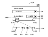
- FIG. 5 is a diagram illustrating an example of the GUI 100 displayed on the monitor 55.
- the GUI 100 is a user interface displayed on the monitor 55. Specifically, the display screen 101, the operation mode setting unit 102, the live mode setting unit 103, the recording date and time selection unit 104, the display time unit setting unit 105, the display target A range setting unit 106, a setting information display unit 107, and a reproduction list 108 are included.
- the GUI 100 is generated by, for example, the sound parameter display control unit 442 and displayed on the monitor 55, and the same applies to the following embodiments.
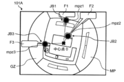
- a captured image GZ that is, a fisheye image
- a sound source visual image (audio heat map MP) superimposed on the captured image
- the sound source visual image is an audio heat map generated by the signal processing unit 44 based on the sound collected by the microphone array MA. That is, the audio heat map is map data that visually indicates in which position the sound source exists in the captured image GZ. Note that the audio heat map may be entire map data that covers the entire area of the captured image GZ, or partial map data that targets only the position where the sound source exists in the captured image GZ. It doesn't matter.
- a designated area FR designated by a user operation is displayed as a place with a large sound parameter (in other words, a place where a sound is generated, that is, a sound source) with a blue rectangular frame.
- areas mpz1 and mpz2 having a sound parameter larger than the sound parameter of the designated area FR are displayed in a substantially circular red shape to indicate different sound source positions.
- the operation mode setting unit 102 has radio buttons that can be selected by the user.
- the operation mode setting unit 102 calculates using, for example, a live mode for displaying a composite image (see above) displayed on the display screen 101 in real time, and past image data and sound data recorded in the recording device 70.
- One of the date and time designation modes for displaying a composite image (see above) corresponding to a past designated date and time can be selected based on the sound parameters that have been set.
- the color of the radio button corresponding to the selected mode changes.
- the date / time designation mode is selected. In the following description, it is assumed that the date / time designation mode is selected.
- the live mode setting unit 103 has a pull-down menu that can be selected by the user, and sets the selected visualization target time.
- the selected visualization target time In FIG. 5, for example, “the past one hour” is set as the visualization target time. This specifies that, for example, sound data and image data from the present to the past one hour before are used to generate the above-described composite image.
- the recording date and time selection unit 104 has a pull-down menu that can be selected by the user, and sets the selected recording date and time.
- a date “2016/5/1” is set as the recording date and time information.
- This pull-down menu includes items that can set the time zone in addition to the date.
- the display time unit setting unit 105 has a pull-down menu that can be selected by the user, and sets the selected display time unit. In FIG. 5, for example, “1 hour” is set.
- the display target range setting unit 106 includes a slide bar for designating a time zone (time range) that is a display target of the above-described composite image, and the user moves the slider 106z on the time axis to display the time zone to be displayed.
- (Time range) is set.
- the slider 106z has a rectangular shape, for example.
- the left side of the rectangle indicating the slider 106z indicates the display start time t0 of the time zone (time range) described above, and the length of the rectangle indicates the display time unit ⁇ (here, 1 hour).
- the right side of the rectangle indicating the slider 106z indicates the display end time (t0 + ⁇ ).
- time range a display target of the above-described composite image
- the display target time zone (that is, the start time and end time of the display time unit ⁇ ) can be changed on the time axis of “9:00 to 17:00”.
- the display of the slide bar of the display target range setting unit 106 in the time zone “9:00 to 17:00” is merely an example, and another example is “0:00 to 23” indicating one day. : 59 ".
- the setting information display unit 107 displays the designated area FR designated by the user operation and the accumulated utterance time of the designated area FR.
- the designated area FR is a rectangular area represented by the center coordinates (X, Y). In FIG. 5, for example, the center coordinates (X, Y) of the designated area FR are (100, 200).
- the total utterance time is, for example, 4 minutes and 20 seconds.
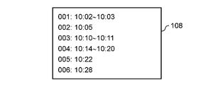
- the reproduction list 108 displays, in chronological order, the start time of the voice detection period in which the voice is detected in the designated area FR within the time range designated by the user operation.
- the browsing device 30 can reproduce the sound from the start time by outputting the sound from the speaker 50.
- voice detection periods having start times of “10:05:05”, “10:05:30”, and “10:06:10” are displayed in the order of labels.
- the mark 108z is indicated by the sound parameter display control unit 442.
- the recording device 70 performs recording operation (that is, recording) of an image taken by the omnidirectional camera CA, recording operation (that is, recording) of the sound collected by the microphone array MA, and calculation and storage of sound parameters. The operation will be described.
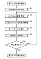
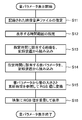
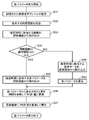
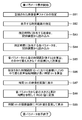
- FIG. 6 is a flowchart for explaining in detail an example of each operation procedure of calculation and storage of sound parameters in the recorder R2 of the first embodiment.
- the operation unit 58 of the browsing device 30 receives a recording operation instruction from the user (S1). When an instruction for a recording operation by the user is accepted, the recorder R1 starts recording image data of an image captured by the omnidirectional camera CA using this instruction as a trigger (S2). In addition, the recorder R1 starts recording the voice data of the voice collected by the microphone array MA (S3).
- the sound parameter calculation unit 71 of the recorder R2 calculates the sound pressure, which is a sound parameter, based on the image data and sound data recorded in the recorder R1 (S4).
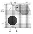
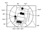
- FIG. 7 is a diagram for explaining an example of calculating sound parameters.
- the sound parameter is calculated for each pixel constituting the captured image GZ of the monitoring area SA shown in FIG.
- the sound parameter for each pixel is superimposed on the captured image GZ.
- the captured image GZ is divided into, for example, squares (that is, pixels) of 0 to Nx and 0 to Ny.
- a sound parameter indicating the loudness of the sound is calculated in units of squares.
- the loudness (sound pressure) of a certain time t at the coordinates (i, j) on the captured image GZ is represented by f (t, i, j).
- the loudness of a certain time t may be an instantaneous value, or may be an average value, a maximum value, or an added value of a certain time width (for example, 1 minute).
- the sound parameter calculation unit 71 of the recorder R2 calculates the sound volume time cumulative value F t0, ⁇ (i, j) from the display start time t0 to the display end time (t0 + ⁇ ) (see FIG. 5) using the formula (1). ).
- the sound parameter calculation unit 441 performs the same processing as the calculation processing described above by the sound parameter calculation unit 71 of the recorder R2.
- the color information conversion unit 443 normalizes the time accumulated value F t0, ⁇ (i, j) of the sound volume at all coordinates (i, j) on the captured image GZ, and performs normalization.
- the values are converted into RGB values constituting the audio heat map MP (see equations (2) to (4)).
- Red value is R t0, ⁇ (i, j )
- the green value is G t0, ⁇ (i, j )
- a blue value i.e., B value B t0, ⁇ (i, j), which are
- Equation (2), Equation (3), and Equation (4) are expressed by Equation (2), Equation (3), and Equation (4), respectively.
- k R , k G , and k B are constants indicating the strengths of the red element, the green element, and the blue element, respectively.
- represents the norm F.
- the color information conversion unit 443 represents the sound source visual image with RGB values. However, for example, the color information conversion unit 443 may represent other color information such as YUV values, or use all three values of RGB values. The sound source visual image may be represented without doing so. Furthermore, the color information conversion unit 443 may represent the sound source visual image as opacity using an alpha value.
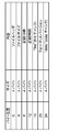
- FIG. 8 is a diagram showing an example of the structure of a file in which the sound parameters of the first embodiment are stored.
- the file in which the sound parameters are stored includes a file header field, a file size field, a recording date / time field, a recording time field, a “fmt” (fmt (format) chunk) field, a format version field, and a “data” field.
- "(Data chunk)” column Each element constituting the sound parameter has a size of 4 bytes.
- the actual data of the sound parameter is stored in the “data” (data chunk) column.
- the sound parameter storage unit 72 uses the sound parameter calculated by the sound parameter calculation unit 71 (for example, f (t, i indicating the volume of sound) as a part of the recorded data in the sound parameter storage unit 72. , J), including the accumulated time value F t0, ⁇ (i, j) of the sound volume (S5). At this time, time information such as recording (recording, recording) date and time is also stored as a part of the recording data.
- the recording device 70 confirms whether or not there is a recording stop request by the user made through the operation unit 58 (S6).
- S6 NO the processing of the recording device 70 returns to step S2, and the same processing is repeated until there is a stop request.
- the recording apparatus 70 ends this operation.
- FIG. 9 is a flowchart illustrating in detail an example of an operation procedure for displaying sound parameters according to the first embodiment.
- the operation unit 58 of the browsing device 30 receives a video / audio file including image data and sound data recorded in the recorder R1 designated by a user operation (S11).
- a video / audio file is designated, information on the recording date and time set by the recording date and time selection unit 104 is used.
- the display target date / time specifying unit 452 receives the time range of the display target specified by the user operation via the operation unit 58 (S12).
- the playback control device 40 reads video corresponding to the designated time range from the recorder R1 (S13).
- the sound parameter calculation unit 441 reads sound parameters corresponding to the time range specified in step S12 from the recorder R2 (S14). Based on the read sound parameter, the color information conversion unit 443 converts the sound volume time cumulative value F into an RGB value according to Equations (2) to (4) (S15). The RGB values are set in 256 levels within the range of 0 to 255. For example, the color information conversion unit 443 calculates the value of blue B according to Equation (5), and calculates the value of red R according to Equation (6).
- the magnitude of the period accumulation value F t0 sound, tau (i, j) when the value obtained by normalizing the (conveniently referred to as "normalized value”) is smaller than "0.2"
- this pixel blue corresponding to the normalized value is colored, and red is not colored. Accordingly, the pixel exhibits a color ranging from transparent to bluish.
- the sound parameter display control unit 442 converts the captured image GZ captured by the omnidirectional camera CA (for example, the captured image GZ at the start time of the time range specified by the user operation; the same applies hereinafter) in step S15.
- the sound source visual image (sound heat map MP) based on the RGB values is superimposed to generate a composite image and display it on the monitor 55 (S16). Thereafter, the sound parameter display control unit 442 ends this operation.
- the sound parameter calculation unit 441 calculates the time accumulated value F of the sound volume is shown, the sound parameter display control unit 442 may perform the calculation.
- the time of the display target range setting unit 106 is set.
- the display time unit ⁇ corresponding to the width (rectangular length) of the slider 106z arranged on the axis changes.
- the center position of the slider 106z is at time t1
- a composite image of the captured image GZ and the audio heat map MP at time t1 (for example, 10:05:05) is displayed on the display screen 101.
- the sound heat map MP two loud areas mpz1 and mpz2 are displayed in a substantially circular shape.
- FIG. 10 is a diagram illustrating an example of the GUI 100 displayed at the time t ⁇ b> 2 displayed on the monitor 55.
- the louder region mpz3 is moving compared to FIG. 5 due to the change of the person speaking in the captured image GZ.
- the omnidirectional camera CA images the monitoring area SA.
- the microphone array MA picks up the sound of the monitoring area SA.
- the recording device 70 records the captured image and imaging time captured by the omnidirectional camera CA in association with the sound collected by the microphone array MA.
- the sound parameter calculation units 71 and 441 generate sound parameters indicating the loudness of the monitoring area SA at the time of imaging based on the sound collected by the microphone array MA during imaging by the omnidirectional camera CA. For every predetermined unit of pixels constituting the captured image.
- the sound parameter storage unit 72 stores the sound parameters calculated by the sound parameter calculation units 71 and 441 in association with position information on the captured image at the imaging time.
- the sound parameter display control unit 442 superimposes the sound source visual image based on the sound parameters for each predetermined unit of the pixels calculated by the sound parameter calculation units 71 and 441 for each predetermined unit of the pixels constituting the captured image of the monitoring area SA. And displayed on the monitor 55. At this time, the sound parameter display control unit 442 monitors the sound source visual image based on the cumulative value F of the sound volume in the time range of the sound parameter stored in the sound parameter storage unit 72 according to the specification of the time range. The image is superimposed and displayed on the monitor 55 for each predetermined unit of the pixels constituting the captured image of the area SA.
- the voice monitoring system 5 can specifically visualize the sound source in the monitoring area SA using the sound parameter indicating the magnitude of the sound collected by the microphone array MA.
- color information for example, RGB values
- luminaration a time period
- in-store audio it is possible to obtain not only the loudness but also the amount of conversation that is the cumulative time of the sound (the duration of the audio). Can be analyzed.
- more detailed analysis is possible by combining with video.
- the browsing device 30 represents, as a sound pressure parameter, the volume of sound at a certain time t in coordinates (i, j) on the captured image as f (t, i, j).
- f (t, i, j) a sound time accumulated value F t0, ⁇ (i, j) was calculated.
- the amount of sound information is binarized (that is, compressed) based on the presence or absence of sound detection, and then the sound time accumulated value F t0, ⁇ (i, j) is calculated. .
- the sound parameter calculation unit 71 detects the loudness f (t, i, j) and the sound at the coordinates (i, j) at a certain time t, as shown in Equation (7).
- the parameter f ′ (t, i, j) indicating the presence or absence of sound is calculated by comparing the threshold value Vdet.
- the threshold value Vdet is not a constant, and may be a value Vdet (t) that varies with time, for example.
- the sound parameter calculation unit 71 calculates the sound volume time cumulative value F t0, ⁇ (i, j) from the display start time t0 to the display end time (t0 + ⁇ ) (see FIG. 5) according to the equation (8). To do.
- the sound parameter calculation unit 441 performs the same processing as the calculation processing described above by the sound parameter calculation unit 71 of the recorder R2.
- the color information conversion unit 443, as in the first embodiment calculates the time accumulated value F t0, ⁇ (i, j) of the sound volume at all the coordinates (i, j) on the captured image GZ. Normalization is performed, and the value after normalization is converted into RGB values constituting the audio heat map MP.
- the sound parameter calculation units 71 and 441 use the binarized information indicating the presence or absence of sound detection for the sound volume and the sound parameters.
- the accumulated time value F of the magnitude is calculated.
- the sound accumulated time value F t0, ⁇ (i, j) is calculated. The load can be considerably reduced.
- the browsing device 30 converts the time accumulated value F t0, ⁇ (i, j) of the sound volume for each predetermined unit of pixels into an RGB value and adds a color to the sound source visual image
- the viewing operation is performed as a user operation.
- voice detection is performed uniformly throughout the monitoring area SA.
- the entire display screen 101 of the captured image GZ is colored.
- the time accumulated value F t0, ⁇ (i, j) of the sound volume that satisfies a predetermined condition is satisfied. Only for the RGB values corresponding to the sound parameters.
- the browsing device 30 uses the information “how much time and voice have been detected” in the time range specified by the user operation, and what percentage or more of the specified time range is the voice Based on the condition that the detection has been performed, the sound source visual image of the corresponding pixel is colored.
- the browsing device 30 displays a sound source visual image displayed around the sound source of the sound for a sound that is less than 3 minutes corresponding to 10% thereof. You may make it not color.
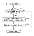
- FIG. 11 is a flowchart illustrating in detail an example of an operation procedure for converting RGB values according to the third embodiment.
- the color information conversion unit 443 determines whether or not the accumulated time value F of the sound volume at the coordinates (i, j) is equal to or greater than the threshold value Vmin (S21).
- the threshold value Vmin is a threshold value for determining whether to color the sound source visual image displayed around the sound source in which the sound is detected.
- the display threshold indicates a relative ratio at which it can be determined that a colored sound source visual image may be displayed around the sound source in which the sound is detected, according to the time range specified by the user operation.
- the color information conversion unit 443 for example, according to Equation (9) and Equation (10), the sound volume time accumulated value F Are converted into RGB values (S22).
- the value of B (blue) is illustrated, and in Formula (10), the value of R (red) is illustrated, and the value of G (green) is, for example, zero.
- the value of G (green) may also be set so as to change according to the magnitude of the accumulated time value F of the loudness as in the formula (9) and the formula (10).
- the threshold value Vmin is set to a value smaller than “0.5”.
- the blue B value represented by B t0, ⁇ (i, j) is “0.
- the value obtained by normalizing the accumulated sound volume time F t0, ⁇ (i, j) is less than 0.5, the red color represented by R t0, ⁇ (i, j) The R value is “0”.
- the blue B value indicates the loudness of the sound.
- the time accumulated value F t0, ⁇ (i, j) changes according to a normalized value, and the red R value is “0”. In this case, the pixels are bluish depending on the volume of the sound.
- the blue B value is a constant value of “51” and red.
- the R value changes in accordance with a value obtained by normalizing the accumulated sound time value F t0, ⁇ (i, j). Therefore, red becomes stronger as the sound becomes louder.
- the browsing device 30 changes the color of the sound source visual image corresponding to the corresponding pixel from colorless to blue to red.
- the sound parameter display control unit 442 generates a composite image by superimposing the sound source visual image (sound heat map MP) based on the RGB values converted in step S22 on the captured image GZ captured by the omnidirectional camera CA. The information is displayed on the monitor 55 (S23). Thereafter, the sound parameter display control unit 442 ends this operation.
- sound source visual image sound heat map MP
- the sound parameter display control unit 442 sets the relative value between the time range specified by the user operation and the accumulated time value of the sound volume in the time range. Based on this, the sound heat map MP (sound source visual image) is displayed with color information. Thereby, the browsing device 30 sets the time range as a display target for a long time when converting the accumulated sound time value F t0, ⁇ (i, j) to an RGB value and coloring the screen. Even so, it can be avoided that the entire screen is colored and difficult to see. Further, the sound parameter display control unit 442 may display the sound heat map MP (sound source visual image) as color information based on the absolute value of the time accumulated value F of the sound volume, and the same effect as described above. Can be obtained.
- the sound heat map MP sound source visual image
- the browsing device 30 converts the accumulated time value F t0, ⁇ (i, j) of the sound volume for each predetermined unit of pixels into an RGB value.
- the RGB value is calculated only for the accumulated time value F t0, ⁇ (i, j) of the sound volume that satisfies a predetermined condition.
- the browsing device 30 uses the information “how long and how much sound is detected” regardless of the time range specified by the user operation, and performs sound detection for a certain time. Color the sound source visual image of the corresponding pixel.
- the RGB conversion operation in the browsing device 30 of the fourth embodiment is the same as that of the third embodiment, the description thereof is omitted.
- the determination of step S21 in FIG. 11 even if the sound volume time accumulated value F is equal to or greater than the threshold value Vmin, “NO” is determined when sound detection is not performed for a certain time as an absolute value. Therefore, the RGB value is not calculated.
- the browsing device 30 can display, for example, only places where utterances have accumulated for 1 minute or more on the screen, and the accumulated time value of sound volume.
- F t0, ⁇ (i, j) into RGB values and coloring the screen, even if the time range is set as a display target with a long time, the entire screen is colored so that it is difficult to see can do.
- the threshold value Vmin is a preset fixed value (for example, a value smaller than “0.5”).
- the user arbitrarily sets the threshold value Vmin. Indicates the case where setting is possible.
- FIG. 12 is a diagram illustrating an example of the GUI 100 displayed on the monitor 55 of the fifth embodiment.
- the same components as those of the GUI 100 of the first embodiment are denoted by the same reference numerals, and the description thereof is omitted.
- the GUI 100 is further provided with a display lower limit setting unit 111.
- the display lower limit setting unit 111 has a pull-down menu 111z, and can arbitrarily set a threshold Vmin condition for determining whether or not to display a sound source visual image based on audio detection on the display screen 101.
- the pull-down menu 111z displays a plurality of items including “display utterances of 5 minutes or more”, “display utterances of 10 minutes or more”, “display utterances of 10% or more”, and “display all”. , Selectable by the user. In FIG. 12, the item “Display utterances of 10 minutes or longer” is selected.
- the display screen 101 is generated by the color information conversion unit 443 based on the sound volume time cumulative value F calculated by the sound parameter calculation unit 441 in accordance with the threshold value Vmin set by the display lower limit setting unit 111.
- An audio heat map MP (that is, a sound source visual image) is displayed superimposed on the captured image GZ.
- the browsing device 30 displays the audio heat map MP with RGB values based on the accumulated sound time F
- the conditions specified by the user operation with respect to the GUI 100 are set. Acceptable. That is, since the user can arbitrarily set a condition based on the threshold value Vmin using the GUI 100, the operability and visibility of the user are improved.
- the browsing device 30 displays the sound source visual image (sound heat map MP) on the monitor 55 based on the sound parameters in the time range specified by the user using the data recorded and recorded in the recording device 70, the time range is displayed.
- the time range is displayed.
- it is long, such as one hour or one day, it may take time to add or average all the sound parameters stored at regular intervals.
- the sound parameter storage is performed in order to shorten the processing time for the calculation of the sound parameter until the sound source visual image (audio heat map MP) is displayed.
- the unit 72 further adds or averages 60 seconds of sound parameters every 60 seconds (60 seconds as one section). Sound parameter) is also calculated and stored.
- the sound parameter display control unit 442 selects a sound parameter to be read in units of 1 second or 60 seconds in accordance with a time range specified by a user operation.
- the sound parameter calculation unit 71 calculates a sound parameter in the selected unit.
- 60 seconds was used as a unit of fixed time, this value is only an example, and arbitrary time, such as longer time, for example, 1 hour, 24 hours, etc. may be used as a unit.
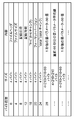
- FIG. 13 is a diagram showing an example of the structure of a file that stores sound parameters in units of 60 seconds according to the sixth embodiment.
- the sound parameters in units of 60 seconds are added to the structure example of the file shown in FIG. 8 in the first embodiment, “sound parameters per second ⁇ 60 pieces”, “sound parameter average value for 60 seconds immediately before”,. Contains the elements.
- the sound parameter storage unit 72 stores sound parameters at a frequency of once per second, and also adds or averages sound parameters for 60 seconds every 60 seconds calculated by the sound parameter calculation unit 71. Save the parameters. Furthermore, the sound parameter storage unit 72 stores a sound parameter calculated by the sound parameter calculation unit 71 by adding or averaging the sound parameters for one hour every hour.
- the sound parameter calculation units 71 and 441 are N (N is an integer equal to or greater than the value 2) of intervals (first intervals) at which the sound parameters are calculated at regular intervals. )
- a sound parameter of a section is calculated by setting an interval (second interval) more than double as one section.
- the sound parameter storage unit 72 stores the sound parameters of the same section.
- the sound parameter calculation unit 441 stores “sound parameters per second ⁇ 60” stored in the sound parameter storage unit 72, or It is obtained by adding or averaging data for one hour using data of “sound parameter average value for the last 60 seconds”. Therefore, the calculation processing is faster than the case where the sound parameters for one hour are multiplied by 3600 sound parameters per second.
- the sound parameters in the designated time range can be calculated relatively easily. Thereby, the calculation time after the user designates the time range can be shortened.
- the sound parameter storage unit 72 does not perform the timing of writing to the recording device 70 at the above-described interval, but temporarily stores it in a memory with a short writing time, and then writes it in a storage medium with a long writing time. Good.
- the sound parameter storage unit 72 when storing the sound parameters at a frequency of once per second, adds the sound parameters for 60 seconds every 60 seconds or averages the sound parameters. saved.
- the sound parameter storage unit 72 stores the sound parameters by adding or averaging the sound parameters for one hour every hour.
- the sound parameter calculation unit 441 reads sound parameters to be read according to a specified time range, for example, in units of 1 second (short period) as the first interval and units in 60 seconds (second period) ( It is calculated in advance in at least three units of a medium period) and an hour unit (long term) which is the third interval.
- the sound parameter storage unit 72 stores the calculated three or more time-unit sound parameters.
- the browsing device 30 is calculated and stored in units of three or more time units according to the time range specified by the user, as in the sixth embodiment.
- a sound parameter storage result that is appropriate (e.g., calculated in the same unit as the time unit of the time range) among the sound parameters being used, the calculation time after the user specifies the time range can be reduced. Can do.
- the sound parameters may be stored every 12 hours and every 24 hours. Furthermore, the sound parameters may be stored together for every hour, 10 minutes, and 1 minute.
- the browsing device 30 displays the sound source visual image (sound heat map MP) on the monitor 55 based on the sound parameters in the time range specified by the user using the data recorded and recorded in the recording device 70, the sound parameters are displayed. If the interval stored in the recorder R2 of the recording device 70 is short, the amount of data to be written per second increases. For this reason, the storage area of the recorder R2 is compressed. On the other hand, depending on the user, when the user wants to see the sound heat map MP in the specified time range after the sound parameter data is recorded in the recorder R2, the user may want to see the sound heat map MP at intervals of 1 second or shorter.
- the sound parameter storage unit 72 stores the sound parameters to be stored at intervals of, for example, 1 second or more (5 seconds or the like).
- the determination unit 46 of the browsing device 30 refers to the sound parameter stored in the sound parameter storage unit 72 according to the time range specified by the user operation or from the sound data recorded in the recorder R1. It is determined whether the sound parameter is calculated.
- FIG. 14 is a flowchart for explaining in detail an example of an operation procedure of sound parameter display according to the eighth embodiment. Since the processing of steps S31 to S33 is the same as the processing of steps S11 to S13 in the first embodiment, the description thereof is omitted.
- the determination unit 46 has a time range in which the sound source visual image (sound heat map MP) is displayed (in other words, a time range specified by a user operation) for storing sound parameters (save interval, for example, 5 seconds) AA1 or more. It is determined whether or not (S34).
- the time range to be displayed is the storage interval AA1 or more (S34, YES)
- the processes of steps S35, S36, and S37 are performed in the same manner as steps S14, S15, and S16 in the first embodiment. That is, the sound parameter calculation unit 441 reads the sound parameter corresponding to the time range specified in step S32 from the recorder R2 (S35). Based on the read sound parameter, the color information conversion unit 443 converts the sound volume time accumulated value F into an RGB value according to Equations (2) to (4) (S36).
- the sound parameter display control unit 442 generates a composite image by superimposing the sound source visual image (sound heat map MP) based on the RGB values converted in step S36 on the captured image GZ captured by the omnidirectional camera CA. The information is displayed on the monitor 55 (S37). Thereafter, the sound parameter display control unit 442 ends this operation.
- sound source visual image sound heat map MP
- step S34 when the time range to be displayed is less than the storage interval AA1 in step S34 (S34, NO), for example, the time range in which the sound source visual image (audio heat map MP) is displayed (in other words, specified by the user operation)
- the (time range) is 1 second
- the sound parameter at intervals of 5 seconds stored in the recorder R2 cannot be used.
- the sound parameter calculation unit 441 reads the original sound data stored in the recorder R1 (S38), and calculates, for example, sound parameters at intervals of 1 second (S39). Thereafter, the processing of the sound parameter calculation unit 441 proceeds to step S36.
- the sound parameter display control unit 442 displays the audio heat map MP (sound source visual image) on the monitor 55 within the time range specified by the user operation. Accordingly, it is selected whether to use the sound parameter stored in the sound parameter storage unit 72 or to calculate and use the sound parameter based on the sound data recorded in the recorder R1.
- the sound parameter storage unit 72 can store the sound parameters stored in the recorder R2 at a storage interval AA1 (for example, 5 seconds or longer) longer than the time range to be displayed. Therefore, a system capable of displaying sound parameters in real time without increasing the amount of calculation during playback is provided, except when recalculating sound parameters using original audio data while suppressing the amount of data stored in the recorder R2. it can.
- the sound parameter calculation unit 441 stores, based on the sound data recorded in the recorder R1, when the user wants to see the sound heat map MP (sound source visual image) in the time range shorter than the storage interval AA1.
- Sound parameters can be calculated and stored at a storage interval (eg, 1 second) shorter than a time range (eg, 3 seconds) shorter than the interval AA1.
- a storage interval eg, 1 second
- a time range eg, 3 seconds
- the browsing device 30 displays a sound source visual image (sound heat map MP) based on sound detection on the captured image GZ based on sound reflected by a wall or an obstacle in the store.
- a sound source visual image sound heat map MP
- the area designating unit 451 serving as an exclusion area setting unit is coordinate information of an area designated by a user operation as a sound collection exclusion area for invalidating sounds collected by the microphone array MA. Set.
- FIG. 15 is a diagram illustrating an example of the GUI 100 displayed on the monitor 55 according to the ninth embodiment.
- a sound collection exclusion area mk1 is displayed on the display screen 101.
- the coordinate information of the sound collection exclusion area mk1 on the captured image GZ may be recorded in association with the data of the captured image GZ of the recorder R1, for example, or may be associated with the data of the captured image GZ in the memory 43 of the browsing device 30. May be stored.
- the sound parameter calculation units 71 and 441 determine whether or not the coordinates indicating the position of the sound source from which the sound is detected are registered as the sound collection exclusion area mk1. Sets the output of the sound parameter to the value 0.
- the browsing device 30 sets the sound collection exclusion area mk1 (exclusion area) for excluding the sound collected by the microphone array MA from the sound collection target.
- the sound parameter calculation units 71 and 441 calculate sound parameters while suppressing sound from the set sound collection exclusion area mk1. As a result, it is possible to prevent the result of voice detection due to speech or the like from being displayed in a place such as a wall or an obstacle where there is clearly no speech. Note that the sound parameter calculation units 71 and 441 may reduce and output the sound from the sound collection exclusion area mk1 as value 0.
- the browsing device 30 uses the captured image GZ designated by a user operation based on information in which a sound source is specifically visualized by a sound source visual image (audio heat map MP).
- the actual sound around the upper sound source can be emphasized and output.
- the directional sound data generation unit 42 emphasizes the sound in the direction from the microphone array MA toward the position of the sound source specified by the user operation with respect to the sound collected by the microphone array MA. Form directivity. This technique is also called a beam former technique.
- the browsing device 30 stores the sound collected by each microphone mounted on the microphone array MA in the recording device 70, and performs signal processing of the sound recorded at the time of reproduction desired by the user, so that the user It is possible to form a directional sound at a location corresponding to the position designated by.
- the number of labels increases and the visibility deteriorates.
- audio for less than a certain time is ignored.
- the voice sections are grouped together. For example, an interval in which the voice detection intervals are longer than N (N is an integer greater than or equal to 2) times is set as one interval. N times is 10 times as an example.
- the sound parameter calculation unit 71 calculates the sound parameter in the section by time averaging or adding the sound parameters in the section gathered together.
- the sound parameter storage unit 72 stores the sound parameters in the calculated section. Thereby, the time required for calculating the sound parameter can be suppressed.
- the voice detection interval is shown to be N times (for example, 10 times) or longer, but may include at least three of a short period, a middle period, and a long period.
- N times for example, 10 times
- data in units of 1 minute, 10 minutes, 1 hour, and 1 day can be stored, and an appropriate section according to the situation such as conversation can be set.
- FIG. 16 is a diagram illustrating an example of loud areas mpz4, mpz5, and mpz6 detected in the monitoring area SA of the tenth embodiment.
- the coordinates (X, Y) designated by the user are expressed as coordinates (Ux, Uy).
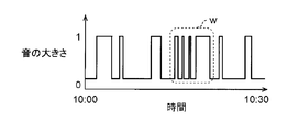
- FIG. 17A and FIG. 17B are diagrams for explaining the state of voice detection in the coordinates (Ux, Uy) of the designated area FR in the designated time range.
- FIG. 17A is a graph showing the presence or absence of sound (change in time of sound detection) in the time range from 10:00 to 10:30.
- FIG. 17B is a diagram showing the reproduction list 108 corresponding to FIG. 17A.
- the label number 001 has a voice detection period of “10:02 to 10:03”. Assume that the sound in this sound detection period is detected, for example, in a loud region mpz6.
- the label number 002 has a voice detection period of “10:05”.
- the sound in this sound detection period is included in the reproduction list 108, but has a sound time of less than 1 second, and is ignored in the present embodiment. Therefore, a sound visual image indicating a loud sound area is not generated.
- the label number 003 has a voice detection period of “10:10 to 10:11”. It is assumed that the sound during this sound detection period is detected, for example, in a loud area mpz4.
- the label number 004 has a voice detection period of “10:14 to 10:20”.
- the sound in this sound detection period is a group of sounds with a short sound detection interval (see reference symbol w in FIG. 17A), and is detected in a loud region mpz5, for example.
- four voice detection periods are combined into one.
- the label number 006 has a voice detection period of “10:28”. Since the voice during this voice detection period is handled in the same manner as the voice detection of the label number 005, the same explanation is omitted.
- FIG. 18 is a flowchart for explaining in detail an example of each operation procedure of speech enhancement processing and reproduction according to the tenth embodiment.
- the reproduction control device 40 performs a sound parameter display process in which the audio heat map MP is superimposed on the captured image GZ (S51). Since the processing in step S51 is the same as the processing in steps S11 to S16 in the first embodiment, the description thereof is omitted. Note that the process of step S51 may be the process shown in the flowchart of FIG. 14 in the eighth embodiment.
- the area designating unit 451 accepts designation of a position where the user wants to reproduce sound in the captured image GZ designated by the user via the operation unit 58 (S52).
- the position to be reproduced is designated by the user moving the designated area FR.
- the directional sound data generation unit 42 emphasizes the sound in the directivity direction toward the position designated by the user operation from the microphone array MA (that is, the directivity of the sound is formed in the directivity direction) (S53).
- the reproduction control unit 41 reproduces the sound in the time range designated by the user from the beginning from the sound in the directivity direction in which directivity is formed (S54). After the audio reproduction, the reproduction control device 40 ends this operation.
- the operation unit 58 receives an operation for designating the position of the audio heat map MP (sound source visual image) displayed on the monitor 55.
- the directional sound data generating unit 42 forms the directivity of the sound collected by the microphone array MA with the position of the designated sound heat map MP as the directional direction, and generates sound data in the directional direction.
- the reproduction control unit 41 reproduces the sound of the sound data in the directional direction and causes the speaker 50 to output the sound.
- the user designates an arbitrary position on the display screen 101 arranged on the GUI 100, for example, a region where the sound is louder than the sound heat map MP displayed within the time range designated by the user operation.
- the reproduction control device 40 may present a plurality of loud areas included in the sound visualization image calculated using the sound parameter information to the user and give the options.
- it is also possible to listen to related sounds such as during conversation without omission by grouping voices with a short voice detection interval.
- the time required for calculating the sound parameter can be reduced.
- the reproduction control unit 41 reproduces the sound from the beginning of the specified time range for a while. During this time, the user sometimes did not hear anything.
- the audiovisual image visualized on the display screen 101 changes with the passage of time due to, for example, movement of a person and the coordinates of a loud area are blurred (displaced). It was sometimes difficult to pinpoint the location of
- the sound parameter display control unit 442 reads sound parameters from the recording device 70, calculates the accumulated time value F of the sound volume in the designated time range, and The time information at which the detection was performed is also stored. At the time of reproduction, the reproduction control unit 41 reproduces the specified time range by adding the time information on which the voice is detected as an offset. As a result, when playback starts, the user can immediately hear the voice.
- the area designation unit 451 uses the coordinates of the loudest voice in the designated area of surrounding Ncm (M pixels), or the voice. Specify the coordinates corrected to the longest detection time. Thus, the user can accurately indicate the position of the sound source (sound direction). Moreover, the browsing apparatus 30 can reproduce
- FIG. 19 is a flowchart for explaining in detail an example of each operation procedure of speech enhancement processing and reproduction according to the eleventh embodiment.
- the same step processes as those shown in the flowchart of FIG. 18 in the tenth embodiment are denoted by the same step numbers, and the description thereof is omitted.
- FIG. 20 is a diagram illustrating an example of the coordinates (Ux, Uy) of the designated area FR selected by the user from the monitoring area SA.
- the designated area FR is selected from the loud areas mpz7, mpz8, and mpz9.
- FIG. 21 is a graph showing an example of a time change of voice detection at the coordinates (Ux, Uy) of the designated area FR.
- the user designates “10:00 to 10:10” as the time range. In this time range, the sound period appears irregularly with respect to the silence period.
- the sound parameter calculation unit 441 calculates the cumulative time value F of the loudness of the sound in the direction in which the directivity is formed in step S61 (directivity direction) using Equation (1). (S62). The sound parameter calculation unit 441 similarly calculates the sound volume time cumulative value F according to the equation (1) for the surrounding coordinates of the coordinates designated by the user (S63).
- the directional sound data generation unit 42 selects the coordinates having the largest sound volume time accumulated value F from the sound volume time accumulated values F calculated in steps S62 and S63.
- the directionality of the sound is formed with the direction from the microphone array MA toward the sound source corresponding to the coordinates as the directivity direction (S64).
- the reproduction control unit 41 estimates an offset time t offset until sound detection is first performed for sound in a directivity direction in which directivity is formed in step S64 (S65).
- the time range is designated as “10:00 to 10:10”.
- the offset time t offset is around “10:04”, and the sound period starts from this timing.
- the reproduction control unit 41 outputs the voice having the directivity formed (emphasized processing) from the time obtained by adding the offset time t offset to the first time in the time range specified by the user, that is, “10: 00 + t offset ”. Playback is performed (S66). Thereafter, the reproduction control device 40 ends this operation. Note that the playback control unit 41 does not play the sound with the directivity formed (emphasized) immediately after the period of “10: 00 + t offset ”, but instead of “10: 00 + t offset ” for a predetermined time ( For example, the sound may be played back several seconds before.
- the reproduction control unit 41 is picked up by the microphone array MA from the audio detection period (sound period) in which the audio is detected in the designated time range. Play the sound.
- the user views the sound visualization image displayed superimposed on the captured image, designates the position and time range to be heard and instructs the start of reproduction, the user hears the sound immediately after the reproduction is started. Will be able to.
- the sound parameter display control unit 442 reads sound parameters from the recording device 70 and performs sound detection when calculating the accumulated time value F of the sound volume in the designated time range. Also keep time information.
- the sound parameter display control unit 442 refers to the sound parameter storage unit 72 and is designated when a plurality of voice detection sections are detected.
- the information item for example, time zone, see FIG. 5
- the sound parameter corresponding to the selected position that is, the coordinates on the captured image GZ
- a list for example, the reproduction list 108
- the position (coordinates) designated by the user may be corrected.
- the time information described in the item is added as an offset to the specified time range and played back. As a result, when playback starts, the user can immediately hear the voice.
- FIG. 22 is a flowchart for explaining in detail an example of each operation procedure of speech enhancement processing and reproduction according to the twelfth embodiment.
- the same step processes as those shown in the flowchart of FIG. 18 in the tenth embodiment are denoted by the same step numbers, and the description thereof is omitted.
- the sound parameter calculation unit 441 performs the processes of steps S51 to S53 of the tenth embodiment (S71), similar to the process of step S61 in the eleventh embodiment.
- the sound parameter calculation unit 441 determines the presence / absence of sound in the above-mentioned directivity direction within the time range specified by the user (S72).
- the sound parameter calculation unit 441 adds the time zone in which it is determined that there is sound as a label of the reproduction list 108 (S73).
- the sound parameter calculation unit 441 stores the time zone in the memory 43 for reproduction.
- the reproduction control unit 41 receives one of the reproduction lists 108 specified by the user via the operation unit 58 (S74).
- the playback control unit 41 plays back the sound from the beginning of one time zone of the specified play list 108 in the time range specified by the user from the sound in which the directivity direction is formed, as in the process of step S54. (S74). After the audio reproduction, the reproduction control device 40 ends this operation.
- the reproduction control unit 41 displays the reproduction list (list of audio detection periods) in the designated time range, and the audio selected from this reproduction list. Play sound during the detection period.
- the sound parameter display control unit 442 performs the time when the sound parameter information item corresponding to the coordinates in the sound parameter is detected.
- the reproduction list 108 is listed according to the information. As described above, the user can listen to a desired voice immediately even when the time range specified by the user is long by selecting an item listed in the reproduction list.
- a moving image in the sound detection period may be displayed instead of the captured image GZ as a background. It is done. In this case, the moving image may be simply reproduced from the beginning of the designated time range, but the relation between the sound source visual image (audio heat map MP) and the moving image becomes difficult to understand.
- the browsing device 30 extracts an image frame of one captured image from a plurality of image frames constituting the moving image instead of the moving image, and uses the sound source visual image (audio heat map MP). ) And the captured image as the background.
- FIG. 23 is a flowchart for explaining in detail an example of an operation procedure of sound parameter display according to the thirteenth embodiment.
- the processing in steps S81 to S84 is the same as the processing in steps S11 to S14 in the first embodiment, and a description thereof will be omitted.
- the sound parameter calculation unit 441 calculates a sound volume time accumulated value F (i, j) at the coordinates (i, j) on the captured image, and the sound volume time accumulated value F having the largest sound volume among them. (I 1 , j 1 ) is calculated (S85). Furthermore, the sound parameter calculation unit 441 uses the time tm having the longest sound detection time in the designated time range (that is, the display start time t0 to the display end time (t0 + ⁇ )) in the coordinates (i 1 , j 1 ). Is calculated (S86).
- the playback control unit 41 extracts an image frame at time tm from an image (moving image) recorded on the recorder R1 in a specified time range (that is, display start time t0 to display end time (t0 + ⁇ )). Is displayed on the screen of the monitor 55 (S87).
- the color information conversion unit 443 converts the sound volume time accumulated value F into RGB values based on the read sound parameters, similarly to step S15 in the first embodiment (S88).
- the sound parameter display control unit 442 superimposes the sound source visual image (sound heat map MP) based on the RGB values converted in step S88 on the image frame at time tm to form a composite image and displays it on the monitor 55 (S89). . Thereafter, the reproduction control device 40 ends this operation.
- the browsing device 30 obtains the time zone having the longest voice detection period in the time range designated by the user operation.
- the reproduction control unit 41 displays a captured image of the monitoring area SA of the scene included in this time zone on which the audio heat map MP is superimposed on the monitor 55.
- the image (captured image) most related to the sound source visual image (audio heat map MP) like a single picture, the relationship between the sound source visual image (audio heat map MP) and the image can be understood. It becomes easy. Therefore, the user can easily grasp the sound source in the video displayed on the monitor 55.
- the browsing device 30 can reproduce the audio part at an early stage even if the sound data in the time range is reproduced. Not limited to this, the user may have to wait until the audio portion is reproduced.
- the browsing device 30 when a time range is designated by a user operation, the browsing device 30 reads and analyzes sound data in the time range from the recorder R1, and the user intuitively and visually determines the voice detection period.
- An analysis result (for example, utterance content, utterance tendency) is displayed on the monitor 55 so as to be discriminated.
- the browsing apparatus 30 displays the utterance content of an analysis result as a speech balloon.
- the user simply designates the sound that he / she wants to play while looking at the monitor 55, and does not wait until the sound part is played back, and the sound is quickly (that is, stress-free). I can hear the part.
- FIG. 24 is a block diagram showing in detail an example of the system configuration of the voice monitoring system 5A of the fourteenth embodiment.
- the same components as those in FIG. 1 are denoted by the same reference numerals, the description thereof is simplified or omitted, and different contents will be described.
- the signal processing unit 44A of the reproduction control device 40A of the browsing device 30A includes an utterance analysis unit 444 in addition to the sound parameter calculation unit 441, the sound parameter display control unit 442, and the color information conversion unit 443.
- the designation unit 45A includes a balloon designation unit 453 in addition to the area designation unit 451 and the display target date / time designation unit 452.
- the utterance analysis unit 444 designates a recording date and time (for example, May 1, 2016), a display time unit (for example, one hour), and a time range RNG (for example, FIG. 25, for example, 10:00 to 11:00) by a user operation. Then, using the sound parameter data recorded in the recorder R2, the utterance tendency and utterance content of the person in the monitoring area SA of the time range RNG are analyzed. The utterance analysis unit 444, for example, determines whether a small number of people (for example, one person) is speaking for a predetermined time or more in the monitoring area SA, or “a large number of persons (for example, two or more persons) is predetermined as the utterance tendency of a person. Analyzing whether you are speaking in less than time.
- the utterance analysis unit 444 has unique threshold values for the number of people and the utterance time, and according to the comparison result with these threshold values, “whether a small number of people (for example, one person) speaks for a predetermined time or more” or “ Analyzes whether a large number of people (for example, two or more people) are speaking in less than a predetermined time.
- the utterance analysis unit 444 displays the analysis result of the utterance tendency of the person on the GUI 100A of the monitor 55 in association with the utterance period of the person (see FIG. 25).
- FIG. 25 is a diagram illustrating an example of a part of the GUI 100A displayed on the monitor 55 of the fourteenth embodiment.
- the recording date selection unit 104, the display time unit setting unit 105, the display target range setting unit 106, and the seek bar 106A are shown in an enlarged manner.
- a seek bar 106A showing details of the time range RNG is displayed so that details of the time range RNG (for example, 10:00 to 11:00) designated by the user operation can be determined. ing.
- This seek bar 106A is generated and displayed by the speech analysis unit 444. However, the display of the seek bar 106A may be performed by the sound parameter display control unit 442.
- the analysis result of the speech analysis unit 444 is shown from the left end of the seek bar 106A (that is, the display start time 10:00) to the right end (that is, the display end time 11:00).
- the utterance period analyzed that “a small number of people are speaking for a predetermined time or longer (that is, for a long time)” is indicated by, for example, red blocks RR1 and RR2, and “the number of adults is less than a predetermined time ( That is, the speech period analyzed as “speaking in a short period of time” is indicated by, for example, blue blocks BB1 and BB2.
- the top time of each block RR1, BB1, BB2, RR2 (that is, the time corresponding to the left end) is referred to as “search time”.
- the search time indicates the start time when the voice at the time of utterance of a small number of people or a large number of people is detected as an analysis result in the utterance analysis unit 444.
- a situation in which a small number of people speak for a predetermined time or longer means that, for example, a speaker (for example, a moderator or an explainer) continues to moderate in a meeting or the agenda.
- a speaker for example, a moderator or an explainer
- the situation where the large number of people speaks in less than a predetermined time may be a situation where, for example, a plurality of persons exchange opinions on the agenda at a meeting or the like.
- the utterance analysis unit 444 may generate summary information of the utterance content corresponding to the corresponding block when the cursor is brought close to each block by a user operation, and may display the summary information in a pop-up manner.
- the summary information here may be, for example, information obtained from voice data such as a uttered person or utterance content, or other data obtained from the outside.
- voice data such as a uttered person or utterance content
- the person who speaks is the position on the captured image when the utterance is detected (the position of the pixel where the sound parameter is calculated) when the information of the person shown in the captured image is stored in an external DB or the like in advance.
- the person information shown in the above-described captured image can be determined by the speech analysis unit 444.
- the speech balloon designation unit 453 as the speech balloon control unit displays the speech content of the person obtained by the analysis of the speech analysis unit 444 as a speech balloon on the monitor 55 in association with the corresponding person in the captured image GZ.
- the balloon designation unit 453 determines the position on the captured image GZ where the sound source visual image based on the sound parameter corresponding to the utterance content of the person is colorless as the display position of the balloon.
- the balloon designation unit 453 determines that the position on the captured image GZ where the sound source visual image based on the sound parameter corresponding to the utterance content of the person is colored (for example, red or blue) is not used as the display position of the balloon. .
- the sound source visual image is colored, a sound source exists around it, and if the sound source visual image is colorless, there is no sound source around the sound source visual image.
- the position on the captured image GZ where the sound source visual image is colorless can be used as an appropriate display position of the balloon without degrading the visibility.
- FIG. 26 is a diagram illustrating a display example in which the sound source visual image (audio heat map MP) is superimposed on the captured image GZ at the display start time of the time range RNG designated by the user operation.
- FIG. 27 is a diagram illustrating a display example in which the sound source visual image (audio heat map MP) and the utterance contents of a plurality of persons are superimposed on the captured image GZ at the search time designated by the user operation.
- the same components as those in FIG. 26 are denoted by the same reference numerals, and the description will be simplified or omitted, and different contents will be described.
- a sound source visual image (for example, red) based on the sound parameter when the person JB1 is uttered is indicated by a region mpz1
- a sound source visual image (for example, based on the sound parameter when the person JB2 is uttered) Red) and a sound source visual image (for example, blue) are indicated by regions mpz2 and mpz4, respectively
- a sound source visual image (for example, blue) based on a sound parameter when the person JB3 speaks is indicated by a region mpz3.
- sound source visual images (for example, blue color) based on other sound sources that are not human speech are indicated by regions mpz5, mpz6, and mpz7, respectively.
- the balloon designating unit 453 utilizes this characteristic, along lines LN1, LN2, and LN3 connecting the center point O of the captured image GZ and the sound source visual image regions mpz1, mpz2, and mpz3, and from the center point O, respectively.
- the display positions of the balloons F1, F2, and F3 are determined at the separated positions, and the balloons F1, F2, and F3 are displayed, respectively.
- the person shown in the captured image GZ has a head outside the center. In other words, it is often located on the side away from the center point O of the captured image, and the foot is often located on the inner side of the center (that is, the side closer to the center point O of the captured image). From this point of view, if the balloons F1, F2, and F3 are displayed at positions away from the center point O, the balloon is displayed at a position close to the head, so that it is more appropriate as a display position of the balloon.
- FIG. 28 is a flowchart illustrating in detail an example of an operation procedure for displaying sound parameters according to the fourteenth embodiment. Since the processes of steps S91, S92, and S93 are the same as the processes of steps S11, S12, S13, and S14 in the first embodiment, description thereof is omitted.
- the sound parameter display control unit 442 performs, in steps S91 to S93, a sound source that has been subjected to color information conversion based on the sound parameters, for example, in the captured image in the time range RNG (see FIG. 25) designated by the user operation.
- a visual image (sound heat map MP) is generated and displayed superimposed on the captured image GZ on the display screen 101 of the monitor 55 (S94).
- the utterance analysis unit 444 uses the sound parameter data read from the recorder R2 in step S93, The utterance tendency and utterance content of the person in the monitoring area SA of the time range RNG are analyzed (S95). Furthermore, the utterance analysis unit 444 calculates, for each utterance content, a search time when the utterance content of each person is uttered based on the analysis result (S95). As described above, the search time indicates the time of the beginning (left end) of each of the blocks RR1, BB1, BB2, and RR2 in FIG. As the search time is calculated, the speech analysis unit 444 updates the display of the seek bar 106A by coloring the blocks RR1, BB1, BB2, and RR2 indicating the speech periods on the seek bar 106A of the GUI 100A (S96).
- any one of the search times (in other words, any one of the blocks RR1, BB1, BB2, RR2) is designated by the user operation (S97).
- the utterance analysis unit 444 reads out the sound data at the designated search time from the recorder R1 (S98), and generates the text data of the utterance content displayed in the balloon using the sound data (S99).
- the speech analysis unit 444 extracts and generates text data of speech content (for example, conversation content) obtained from the sound data by performing speech recognition processing on the read sound data.
- the speech balloon designation unit 453 determines the display position of the speech balloon including the utterance content generated in step S99 based on the sound parameter data at the designated search time (that is, the designated block) (S100).
- the sound parameter display control unit 442 reads a captured image (for example, a captured image captured at the search time) at the specified search time (that is, the specified block) from the recorder R1 (S101).
- the sound parameter display control unit 442 adds a sound source visual image (sound heat map MP) that has been subjected to color information conversion based on sound parameters within the time range of the block including the search time to the captured image at the search time designated by the user operation.
- the generated image is superimposed and displayed on the captured image of the display screen 101 of the monitor 55 (S102).
- the sound parameter display control unit 442 displays a balloon including the text data generated in step S99 at the display position determined in step S100 (see S103, FIG. 27).
- the utterance analysis unit 444 uses the sound parameters stored in the sound parameter storage unit 72 of the recorder R2 according to the time range RNG specified by the user operation. Based on this, the utterance tendency and utterance content of the person in the monitoring area SA of the time range RNG are analyzed.
- the sound parameter display control unit 442 displays the analysis result of the person's speech tendency on the GUI 100A of the monitor 55 in association with the person's speech period (that is, the block of the seek bar 106A in FIG. 25).
- the browsing device 30 displays the analysis result (for example, utterance content, utterance tendency) on the monitor 55 so that the user can intuitively and visually discriminate the voice detection period. it can.
- the browsing apparatus 30 can display the utterance content of an analysis result as a speech balloon.
- the user simply designates the sound that he / she wants to play while looking at the monitor 55, and does not wait until the sound part is played back, and the sound is quickly (that is, stress-free). The part can be heard, and the voice confirmation time can be shortened.
- the utterance analysis unit 444 analyzes whether one person speaks for a predetermined time or more in the monitoring area SA or a plurality of persons speak for less than the predetermined time as the utterance tendency of the person.
- the browsing device 30 can analyze the utterance tendency of the person more specifically and easily in the time range RNG designated by the user operation, and can perform the utterance analysis that is user-friendly and conforms to the user's preference.
- the utterance analysis unit 444 can similarly analyze whether a plurality of people speak for a predetermined time or more, or one person speaks for less than a predetermined time.
- the sound parameter display control unit 442 displays the speech of the person obtained by the analysis by the speech analysis unit 444 as a balloon on the monitor 55 in association with the person in the captured image.
- the browsing apparatus 30 can confirm the utterance content before a user reproduces
- the balloon designation unit 453 determines the position in the captured image where the sound source visual image based on the sound parameter corresponding to the utterance content of the person is colorless as the display position of the balloon. Thereby, if the sound source visual image is colored, a sound source exists around it, and if the sound source visual image is colorless, there is no sound source around the sound source visual image.
- the position on the captured image GZ where the sound source visual image is colorless can be used as an appropriate display position of the balloon without degrading the visibility.
- This disclosure analyzes how long a person has been serving customers at a certain level in the past specified period of time, such as a store, and at what audio level, and the analysis results. Is useful as a voice monitoring system and a voice monitoring method that can improve the accuracy of monitoring analysis.
Landscapes
- Engineering & Computer Science (AREA)
- Signal Processing (AREA)
- Health & Medical Sciences (AREA)
- Physics & Mathematics (AREA)
- Acoustics & Sound (AREA)
- Multimedia (AREA)
- Human Computer Interaction (AREA)
- Audiology, Speech & Language Pathology (AREA)
- Business, Economics & Management (AREA)
- Computational Linguistics (AREA)
- Otolaryngology (AREA)
- Tourism & Hospitality (AREA)
- General Health & Medical Sciences (AREA)
- Quality & Reliability (AREA)
- General Business, Economics & Management (AREA)
- General Physics & Mathematics (AREA)
- Economics (AREA)
- Human Resources & Organizations (AREA)
- Marketing (AREA)
- Primary Health Care (AREA)
- Strategic Management (AREA)
- Theoretical Computer Science (AREA)
- Computer Vision & Pattern Recognition (AREA)
- Game Theory and Decision Science (AREA)
- Closed-Circuit Television Systems (AREA)
- Studio Devices (AREA)
- Circuit For Audible Band Transducer (AREA)
- Obtaining Desirable Characteristics In Audible-Bandwidth Transducers (AREA)
Abstract
In the present invention, a recording device records video images, imaging times, and voices. A sound parameter calculation unit calculates, on the basis of the voices, sound parameters specifying the sound level in a monitored area for each pixel and at fixed intervals during image acquisition. A sound parameter storage unit stores the sound parameters. A sound parameter display control unit displays a voice heat map corresponding to the sound parameter values in a superimposed manner on captured images of the monitored area. At this time, the sound parameter display control unit displays the voice heat map on the basis of cumulative duration values of the sound levels corresponding to a specified time range.
Description
本開示は、モニタリング対象のエリア内の人物の動線を分析するための音声モニタリングシステム及び音声モニタリング方法に関する。
The present disclosure relates to a voice monitoring system and a voice monitoring method for analyzing a flow line of a person in a monitoring target area.
モニタリング対象のエリア(例えば店舗内)の人物(例えば店員、来店客)の動線を分析する技術として、画像解析による人物検知及び人物追跡の技術を用いた動線の可視化技術が知られている。この可視化技術では、人物の移動箇所を分析することは可能であるが、例えば接客が頻繁に行われる飲食店やコンビニエンスストア等の店舗内のどの場所でどの程度の時間、店員及び来店客の会話が行われているか、もしくは来店客が単に立ち止まっているだけであるかを区別することはできない。
As a technique for analyzing a flow line of a person (for example, a store clerk or a customer) in an area to be monitored (for example, in a store), a flow line visualization technique using a person detection and person tracking technique by image analysis is known. . With this visualization technology, it is possible to analyze the location of a person's movement, but for example, how much time, at what location in a store, such as a restaurant or a convenience store where customer service is frequently performed, the conversation between the store clerk and the store visitor It is not possible to distinguish whether or not a visitor is just taking place.
上述した動線の可視化技術に関連する先行技術として、例えば特許文献1に示す画像処理装置が提案されている。この画像処理装置は、カメラにより撮影された画像を処理して会議出席者の顔を検出し、複数のマイクによって音声の到来方向を検出し、ずれ時間情報に基づいて音声を収音する方向を変更し、収音された音声レベルを算出する。また、画像処理装置は、顔検出情報、音声到来方向情報、音声レベル情報を基に、会議室画像の会議出席者の発言者の頭上に、音声レベルを示す画像を表示する。
For example, an image processing apparatus disclosed in Patent Document 1 has been proposed as a prior art related to the flow line visualization technique described above. This image processing apparatus processes the image captured by the camera to detect the face of the meeting attendee, detects the arrival direction of the sound by a plurality of microphones, and determines the direction in which the sound is collected based on the deviation time information. Change and calculate the collected sound level. Further, the image processing apparatus displays an image indicating the audio level on the head of the speaker of the conference attendee in the conference room image based on the face detection information, the voice arrival direction information, and the audio level information.
しかしながら、発言者によって現在発言されている音声の音声レベルの瞬時値が算出され、その算出結果(音声レベルの瞬時値)を示す画像が会議出席者の発言者の頭上に表示されるだけでは、過去に発言された一定期間の音声の音声レベルを算出してその結果を可視化する等の音声分析はできない。従って、例えば店舗内の店員の行動等をモニタリングしている人物(例えば監視者)は、店舗内で店員が過去のある期間に接客していた場合に、どれくらいの時間、どの程度の音声レベルで店員の会話が継続しているのかを視覚的に把握することはできない。
However, if the instantaneous value of the voice level of the voice currently being spoken by the speaker is calculated and an image showing the calculation result (instantaneous value of the voice level) is displayed above the speaker of the conference attendee, Speech analysis such as calculating the speech level of speech for a certain period in the past and visualizing the result is not possible. Therefore, for example, a person who monitors the behavior of a store clerk in a store (for example, a monitor), when the store clerk has been in the store for a certain period of time, at what time and at what audio level It is not possible to visually grasp whether the clerk's conversation continues.
本開示は、店舗等のモニタリング対象のエリアにおいて、指定された過去の一定期間において、人物がどのくらいの時間、どの程度の音声レベルで来店客に対して接客していたか等を分析し、分析結果を視覚的に示し、モニタリング分析精度を向上することを目的とする。
This disclosure analyzes how long a person has been serving customers at a certain level in the past specified period of time, such as a store, and at what audio level, and the analysis results. The purpose is to improve the accuracy of monitoring analysis.
本開示の音声モニタリングシステムは、モニタリング対象のエリアを撮像するカメラと、前記エリアの音を収音するマイクアレイと、前記カメラにより撮像された撮像画像及び撮像時刻と前記マイクアレイにより収音された音とを対応付けて記録するレコーダと、前記カメラの撮像中に前記マイクアレイにより収音された音を基に、撮像時刻における前記エリアの音の大きさを示す音パラメータを、前記撮像画像を構成する画素の所定単位毎に繰り返して算出する音パラメータ算出部と、前記音パラメータ算出部により算出された前記音パラメータを、前記撮像時刻における撮像画像上の位置情報と対応付けて保存する音パラメータ保存部と、前記音パラメータに基づく音源視覚画像を、前記撮像画像を構成する画素の所定単位毎に重畳してモニタに表示する音パラメータ表示制御部と、を備え、前記音パラメータ表示制御部は、時間範囲の指定に応じて、前記音パラメータ保存部に保存された前記音パラメータの前記時間範囲における累計値に基づく前記音源視覚画像を、前記撮像画像を構成する画素の所定単位毎に重畳して前記モニタに表示する。
The voice monitoring system according to the present disclosure includes a camera that captures an area to be monitored, a microphone array that collects sound of the area, a captured image captured by the camera, a capturing time, and sound that is captured by the microphone array. A sound parameter indicating the loudness of the area at the time of image capturing based on the sound collected by the microphone array during image capturing by the camera and a recorder that records sound in association with sound; A sound parameter calculation unit that repeatedly calculates for each predetermined unit of the constituent pixels, and a sound parameter that stores the sound parameter calculated by the sound parameter calculation unit in association with position information on the captured image at the imaging time A sound source visual image based on the storage unit and the sound parameter is superimposed for each predetermined unit of pixels constituting the captured image. A sound parameter display control unit for displaying on a monitor, and the sound parameter display control unit converts the sound parameter stored in the sound parameter storage unit to a cumulative value in the time range according to designation of the time range. The sound source visual image based on is superimposed on every predetermined unit of pixels constituting the captured image and displayed on the monitor.
また、本開示の撮像システムは、前記画像処理装置と、前記複数のカメラと、前記表示入力装置とを備える。
The imaging system according to the present disclosure includes the image processing device, the plurality of cameras, and the display input device.
また、本開示の音声モニタリング方法は、カメラと、マイクアレイと、レコーダと、再生制御装置とを含む音声モニタリングシステムにおける音声モニタリング方法であって、前記カメラは、モニタリング対象のエリアを撮像し、前記マイクアレイは、前記エリアの音を収音し、前記レコーダは、前記カメラにより撮像された撮像画像及び撮像時刻と前記マイクアレイにより収音された音とを対応付けて記録し、前記再生制御装置は、前記カメラの撮像中に前記マイクアレイにより収音された音を基に、撮像時刻における前記エリアの音の大きさを示す音パラメータを、前記撮像画像を構成する画素の所定単位毎に繰り返して算出し、前記再生制御装置は、算出された前記音パラメータを、前記撮像時刻における撮像画像上の位置情報を対応付けて前記レコーダに保存し、前記再生制御装置は、前記音パラメータに基づく音源視覚画像を、前記撮像画像を構成する画素の所定単位毎に重畳してモニタすることを特徴とし、前記再生制御装置は、時間範囲の指定に応じて、前記レコーダに保存された前記音パラメータの前記時間範囲における累計値に基づく前記音源視覚画像を、前記撮像画像を構成する画素の所定単位毎に重畳して前記モニタに表示する。
Further, the audio monitoring method of the present disclosure is an audio monitoring method in an audio monitoring system including a camera, a microphone array, a recorder, and a playback control device, wherein the camera images an area to be monitored, The microphone array picks up the sound of the area, and the recorder records the picked-up image and pick-up time picked up by the camera in association with the sound picked up by the microphone array, and the playback control device Is based on the sound picked up by the microphone array during imaging by the camera, and repeats a sound parameter indicating the loudness of the area at the imaging time for each predetermined unit of the pixels constituting the captured image. The reproduction control apparatus compares the calculated sound parameter with position information on the captured image at the imaging time. The reproduction control device monitors the sound source visual image based on the sound parameter by superimposing it on a predetermined unit basis of pixels constituting the picked-up image, and the reproduction control device The sound source visual image based on the cumulative value in the time range of the sound parameter stored in the recorder is superimposed for each predetermined unit of pixels constituting the captured image in accordance with the specification of the time range. Display on the monitor.
本開示によれば、店舗等のモニタリング対象のエリアにおいて、指定された過去の一定期間において、人物がどのくらいの時間、どの程度の音声レベルで来店客に対して接客していたか等を分析し、分析結果を視覚的に示し、モニタリング分析精度を向上することができる。
According to the present disclosure, in a monitoring target area such as a store, an analysis is made of how long a person has been serving a customer at what audio level during a specified past certain period, The analysis result can be shown visually and the monitoring analysis accuracy can be improved.
以下、適宜図面を参照しながら、本開示に係る音声モニタリングシステム及び音声モニタリング方法を具体的に開示した各実施形態を詳細に説明する。但し、必要以上に詳細な説明は省略する場合がある。例えば既によく知られた事項の詳細説明や実質的に同一の構成に対する重複説明を省略する場合がある。これは、以下の説明が不必要に冗長になるのを避け、当業者の理解を容易にするためである。なお、添付図面及び以下の説明は、当業者が本開示を十分に理解するために提供されるのであって、これらにより請求の範囲に記載の主題を限定することは意図されていない。
Hereinafter, embodiments that specifically disclose the voice monitoring system and the voice monitoring method according to the present disclosure will be described in detail with reference to the drawings as appropriate. However, more detailed description than necessary may be omitted. For example, detailed descriptions of already well-known matters and repeated descriptions for substantially the same configuration may be omitted. This is to avoid the following description from becoming unnecessarily redundant and to facilitate understanding by those skilled in the art. The accompanying drawings and the following description are provided to enable those skilled in the art to fully understand the present disclosure, and are not intended to limit the claimed subject matter.
(第1の実施形態)
図1は、第1の実施形態の音声モニタリングシステム5の店舗への設置例を示す図である。音声モニタリングシステム5は、例えば飲食店やコンビニエンスストア等の店舗200に設置され、店長等の監視者によりモニタリングされる対象(例えば店員)の接客状況をモニタリングする。なお、以下の説明では、音声モニタリングシステム5は、店舗内に設置されるとして説明するが、設置先は店舗に限定されず、例えば工場、図書館等の公共施設、オフィス内に設置されてよい。店舗200には、多くの商品が陳列された商品棚201、カウンタ202等が設置されている。カウンタ202は、接客の一例として、来店客が購入した商品の精算等を行うために使用され、例えばレジカウンターである。商品の清算等を行う際、店員p1と来店客p2は、通常、カウンタ202を挟んで対面し、会話する。 (First embodiment)
FIG. 1 is a diagram illustrating an installation example of avoice monitoring system 5 according to the first embodiment in a store. The voice monitoring system 5 is installed in a store 200 such as a restaurant or a convenience store, for example, and monitors the customer service status of a target (for example, a store clerk) monitored by a monitor such as a store manager. In the following description, the voice monitoring system 5 is described as being installed in a store. However, the installation destination is not limited to a store, and may be installed in a public facility such as a factory or a library, or in an office. In the store 200, a product shelf 201 on which many products are displayed, a counter 202, and the like are installed. As an example of customer service, the counter 202 is used to check out products purchased by customers, and is, for example, a cashier counter. When the product is cleared, the store clerk p1 and the customer p2 usually face each other across the counter 202 and have a conversation.
図1は、第1の実施形態の音声モニタリングシステム5の店舗への設置例を示す図である。音声モニタリングシステム5は、例えば飲食店やコンビニエンスストア等の店舗200に設置され、店長等の監視者によりモニタリングされる対象(例えば店員)の接客状況をモニタリングする。なお、以下の説明では、音声モニタリングシステム5は、店舗内に設置されるとして説明するが、設置先は店舗に限定されず、例えば工場、図書館等の公共施設、オフィス内に設置されてよい。店舗200には、多くの商品が陳列された商品棚201、カウンタ202等が設置されている。カウンタ202は、接客の一例として、来店客が購入した商品の精算等を行うために使用され、例えばレジカウンターである。商品の清算等を行う際、店員p1と来店客p2は、通常、カウンタ202を挟んで対面し、会話する。 (First embodiment)
FIG. 1 is a diagram illustrating an installation example of a
音声モニタリングシステム5は、マイクアレイ・カメラ装置10と、閲覧装置30と、記録装置70とを含む構成である。マイクアレイ・カメラ装置10は、マイクアレイMAと全方位カメラCAとが同軸方向に組み合わされて一体化して構成され、カウンタ202の上方に固定して取り付けられている。例えば、マイクアレイ・カメラ装置10は、店舗200の天井に取り付けられる。全方位カメラCAは、カウンタ202を含むモニタリングエリアSAを撮像する。モニタリングエリアは、音声モニタリングシステム5により店員等の接客状況がモニタリングされる対象のエリアであり、以下同様とする。マイクアレイMAは、モニタリングエリアSAを覆う領域から発せられる音を収音する。
The voice monitoring system 5 includes a microphone array camera device 10, a browsing device 30, and a recording device 70. The microphone array / camera apparatus 10 is configured by integrally combining a microphone array MA and an omnidirectional camera CA in a coaxial direction, and is fixedly mounted above the counter 202. For example, the microphone array camera device 10 is attached to the ceiling of the store 200. The omnidirectional camera CA images the monitoring area SA including the counter 202. The monitoring area is an area to be monitored by the voice monitoring system 5 for the situation of customer service, etc., and so on. The microphone array MA collects sound emitted from the area covering the monitoring area SA.
閲覧装置30は、店舗200のバックヤード200zに配置され、全方位カメラCAにより撮像された画像(撮像画像)を閲覧可能に表示し、更に、マイクアレイMAにより収音された音をスピーカ50(図2参照)から出力する。
The browsing device 30 is arranged in the backyard 200z of the store 200, displays an image (captured image) captured by the omnidirectional camera CA so that it can be browsed, and further, the speaker 50 ( (See FIG. 2).
レコーダとしての記録装置70は、閲覧装置30と同様、店舗200のバックヤード200zに配置され、全方位カメラCAにより撮像された画像(撮像画像)及び撮像時刻と、マイクアレイMAにより収音された音及び収音時刻とを対応付けて記録する。また、記録装置70は、一定間隔毎に算出された音パラメータ(後述参照)を繰り返し保存する。
The recording device 70 as a recorder is arranged in the backyard 200z of the store 200, as with the browsing device 30, and is picked up by an image (captured image) and imaged time taken by the omnidirectional camera CA, and by the microphone array MA. Sounds and sound collection times are recorded in association with each other. Further, the recording device 70 repeatedly stores sound parameters (see later) calculated at regular intervals.
図2は、第1の実施形態の音声モニタリングシステム5のシステム構成の一例を詳細に示すブロック図である。マイクアレイ・カメラ装置10、閲覧装置30、及び記録装置70は、ネットワークNWを介して、相互にデータ通信可能に接続される。ネットワークNWは、有線ネットワーク(例えばイントラネット、インターネット)でもよいし、無線ネットワーク(例えば無線LAN(Local Area Network))でもよい。
FIG. 2 is a block diagram showing in detail an example of the system configuration of the voice monitoring system 5 of the first embodiment. The microphone array / camera device 10, the browsing device 30, and the recording device 70 are connected to each other via a network NW so that data communication can be performed. The network NW may be a wired network (for example, an intranet or the Internet) or a wireless network (for example, a wireless LAN (Local Area Network)).
記録装置70は、各種のデータを記録するものであり、レコーダR1とレコーダR2とを含む。レコーダR1は、マイクアレイMAにより収音された音のデータ及び収音時刻と、全方位カメラCAにより撮像された撮像画像のデータ及び撮像時刻とを対応付けて記録する。収音時刻は、マイクアレイMAから送信された音のデータに含まれる時刻情報の時刻でもよいし、マイクアレイMAから送信された音のデータがレコーダR1により受信された時の時刻でもよい。同様に、撮像時刻は、全方位カメラCAから送信された撮像画像のデータに含まれる時刻情報の時刻でもよいし、全方位カメラCAから送信された撮像画像のデータがレコーダR1により受信された時の時刻でもよい。
The recording device 70 records various data and includes a recorder R1 and a recorder R2. The recorder R1 records the sound data and sound collection time collected by the microphone array MA in association with the data and the image capture time of the captured image captured by the omnidirectional camera CA. The sound collection time may be a time of time information included in sound data transmitted from the microphone array MA, or may be a time when sound data transmitted from the microphone array MA is received by the recorder R1. Similarly, the imaging time may be the time of time information included in the captured image data transmitted from the omnidirectional camera CA, or when the captured image data transmitted from the omnidirectional camera CA is received by the recorder R1. The time of
レコーダR2は、音パラメータ算出部71及び音パラメータ保存部72を有する。
The recorder R2 has a sound parameter calculation unit 71 and a sound parameter storage unit 72.
音パラメータ算出部71は、レコーダR1に記録された音データ、あるいはマイクアレイMAにより収音された音データを基に、音パラメータを算出する。以下の説明において、音パラメータは、マイクアレイMAにより収音された音の大きさを示すパラメータであり、例えば音圧である。なお、音パラメータは、音圧に限らず、音量レベルでもよいし、単に音の有無、あるいは音圧と音声検知時間とをかけた量等であってもよい。音パラメータ算出部71の音パラメータの算出処理の詳細は、後述する音パラメータ算出部441の音パラメータの算出処理と同一であるため、ここでは説明を省略する。
The sound parameter calculation unit 71 calculates a sound parameter based on the sound data recorded in the recorder R1 or the sound data collected by the microphone array MA. In the following description, the sound parameter is a parameter indicating the volume of sound collected by the microphone array MA, for example, sound pressure. Note that the sound parameter is not limited to sound pressure, but may be a volume level, or simply the presence or absence of sound, or an amount obtained by multiplying sound pressure and sound detection time. The details of the sound parameter calculation process of the sound parameter calculation unit 71 are the same as the sound parameter calculation process of the sound parameter calculation unit 441 described later, and thus the description thereof is omitted here.
音パラメータ保存部72は、音パラメータ算出部71により算出された音パラメータを、算出時の時刻情報と対応付けて保存する。なお図2では、記録装置70は、レコーダR1とレコーダR2とが別装置として構成されているが、レコーダR1とレコーダR2とが一体化された構成でもよい。また、図2に示すように、レコーダR2は、レコーダR1に記録されている記録データ(つまり、画像データ及び撮像時刻のデータ、並びに、音データ及び収音時刻のデータ)を更に記録してもよい。
The sound parameter storage unit 72 stores the sound parameter calculated by the sound parameter calculation unit 71 in association with the time information at the time of calculation. In FIG. 2, the recorder R1 and the recorder R2 are configured as separate devices in the recording device 70, but may be configured such that the recorder R1 and the recorder R2 are integrated. In addition, as shown in FIG. 2, the recorder R2 may further record recording data (that is, image data and imaging time data, sound data and sound collection time data) recorded in the recorder R1. Good.
閲覧装置30は、再生制御装置40と、スピーカ50と、モニタ55と、操作部58とを含む構成である。再生制御装置40は、全方位カメラCAにより撮像された撮像画像のデータをモニタ55に表示したり、マイクアレイMAにより収音された音のデータをスピーカ50から再生したりする。再生制御装置40は、再生制御部41、指向音データ生成部42、メモリ43、信号処理部44、指定部45及び判断部46を有する。
The browsing device 30 includes a playback control device 40, a speaker 50, a monitor 55, and an operation unit 58. The reproduction control device 40 displays the data of the picked-up image picked up by the omnidirectional camera CA on the monitor 55 and reproduces the sound data picked up by the microphone array MA from the speaker 50. The reproduction control device 40 includes a reproduction control unit 41, a directional sound data generation unit 42, a memory 43, a signal processing unit 44, a designation unit 45, and a determination unit 46.
再生制御部41は、例えば監視者(以下、「ユーザ」ともいう)により一定の時間範囲の指定操作があった場合に、レコーダR1に記録された音データ及び画像データから該当する時間範囲の音データ及び画像データを取得し、音データをスピーカ50により音声出力させ、更に、画像データをモニタ55に表示させる。
For example, when the monitoring controller (hereinafter also referred to as a “user”) performs an operation for specifying a certain time range, the reproduction control unit 41 uses the sound data and image data recorded in the recorder R1 to perform the sound within the corresponding time range. Data and image data are acquired, sound data is output as sound through the speaker 50, and the image data is further displayed on the monitor 55.
また、再生制御部41は、監視者により一定の時間範囲の指定操作並びにモニタ55に表示された撮像画像上に対する位置の指定操作があると、後述する指向音データ生成部42に対し、指定された時間範囲の音データの強調処理を指示する。再生制御部41は、指向音データ生成部42から出力された強調処理済みの音データをスピーカ50により音声出力させて再生する。
In addition, the reproduction control unit 41 is designated to the directional sound data generation unit 42 described later when the monitor performs a designation operation for a certain time range and a designation operation for a position on the captured image displayed on the monitor 55. The sound data in the specified time range is instructed to be emphasized. The reproduction control unit 41 reproduces the emphasized sound data output from the directional sound data generation unit 42 by outputting the sound through the speaker 50.
指向音強調部としての指向音データ生成部42は、例えば再生制御部41の指示に応じて、レコーダR1に記録されている音データを用いて、マイクアレイMAから、例えば店長等の監視者の操作により指定された撮像画像上の位置に対応する音源位置に向かう方向の音を指向方向として強調処理する。具体的には、指向音データ生成部42は、指向方向に対して、音声の指向性を形成することで、指向方向の音声が強調処理された音のデータを生成する。
The directional sound data generating unit 42 as the directional sound emphasizing unit uses, for example, sound data recorded in the recorder R1 in response to an instruction from the reproduction control unit 41, from the microphone array MA, for example, by a supervisor such as a store manager. The sound in the direction toward the sound source position corresponding to the position on the captured image designated by the operation is emphasized as the directivity direction. Specifically, the directional sound data generation unit 42 generates sound data in which sound in the directional direction is emphasized by forming sound directivity with respect to the directional direction.
メモリ43は、例えばRAM(Random Access Memory)又はHDD(Hard Disk Drive)を用いて構成され、音パラメータ算出部441により算出された音パラメータや一定期間分の音パラメータの時間累計値F等の各種情報(後述参照)を記憶する。また、メモリ43は、後述するGUI100(図5参照)に表示される、録画日時、表示時間単位、指定エリアの座標、再生リスト等の各種情報を記憶する。
The memory 43 is configured by using, for example, a RAM (Random Access Memory) or an HDD (Hard Disk Drive), and various types such as a sound parameter calculated by the sound parameter calculation unit 441 and a time accumulated value F of the sound parameter for a certain period. Information (see later) is stored. Further, the memory 43 stores various information such as a recording date and time, a display time unit, coordinates of a designated area, a reproduction list, and the like displayed on a GUI 100 (see FIG. 5) described later.
信号処理部44は、全方位カメラCAから配信された撮像画像(つまり、現在のライブ映像を構成する画像)又はレコーダR1に記録された撮像画像(つまり、過去の録画映像を構成する画像)に重畳される音源視覚画像(後述参照)を生成する。信号処理部44は、音パラメータ算出部441、音パラメータ表示制御部442、及び色情報変換部443を少なくとも有する。
The signal processing unit 44 converts the captured image distributed from the omnidirectional camera CA (that is, the image constituting the current live video) or the captured image recorded on the recorder R1 (that is, the image constituting the past recorded video). A sound source visual image to be superimposed (see later) is generated. The signal processing unit 44 includes at least a sound parameter calculation unit 441, a sound parameter display control unit 442, and a color information conversion unit 443.
音パラメータ算出部441は、全方位カメラCAにより撮像された撮像画像の画像データとマイクアレイMAにより収音された音の音データとを基に、画像データを構成する一つ一つの画素毎に音パラメータ(例えば音圧)を算出する。本実施形態を含む各実施形態では、音パラメータ算出部441は、例えば音パラメータを算出する際、マイクアレイMAから、算出対象となる画素に対応するモニタリングエリアSAの位置に向かう方向に指向性(後述参照)を形成してその方向の音を強調処理した上で、音の有無を判断して音圧を算出する。また、音パラメータ算出部441は、画像データを構成する一つ一つの画素毎に、該当する画素の位置に音圧の算出値を割り当てた音圧マップを生成する。なお、音パラメータ算出部441は、画素単位で算出した音圧値を該当する画素の位置に割り当てた音圧マップを生成すると説明したが、一つ一つの画素毎に音圧を算出せず、所定数(例えば2×2=4個、3×3=9個)の画素からなる画素ブロック単位で音圧値の平均値を算出し、該当する所定数の画素に対応する音圧値の平均値を割り当てることで、音圧マップを生成してもよい。
The sound parameter calculation unit 441 uses the image data of the captured image captured by the omnidirectional camera CA and the sound data of the sound collected by the microphone array MA for each pixel constituting the image data. Sound parameters (for example, sound pressure) are calculated. In each embodiment including this embodiment, when calculating the sound parameter, for example, the sound parameter calculation unit 441 has directivity (in the direction from the microphone array MA toward the position of the monitoring area SA corresponding to the pixel to be calculated). The sound pressure is calculated by determining the presence or absence of sound after emphasizing the sound in that direction. In addition, the sound parameter calculation unit 441 generates a sound pressure map in which a calculated value of sound pressure is assigned to the position of the corresponding pixel for each pixel constituting the image data. The sound parameter calculation unit 441 has been described as generating a sound pressure map in which the sound pressure value calculated in units of pixels is assigned to the position of the corresponding pixel, but does not calculate the sound pressure for each pixel, An average value of sound pressure values is calculated for each pixel block composed of a predetermined number (for example, 2 × 2 = 4, 3 × 3 = 9) of pixels, and the average of the sound pressure values corresponding to the predetermined number of pixels A sound pressure map may be generated by assigning a value.
音パラメータ表示制御部442は、全方位カメラCAから配信された撮像画像(つまり、現在のライブ映像を構成する画像)又はレコーダR1に記録された撮像画像(つまり、過去の録画映像を構成する画像)に音源視覚画像を重畳するための表示制御を行う。音パラメータ表示制御部442の動作の詳細については後述する。
The sound parameter display control unit 442 is a captured image distributed from the omnidirectional camera CA (that is, an image constituting a current live video) or a captured image recorded on the recorder R1 (that is, an image constituting a past recorded video). Display control for superimposing a sound source visual image on the sound source). Details of the operation of the sound parameter display control unit 442 will be described later.
色情報変換部443は、音パラメータ算出部441により算出された音パラメータを基に、RGB値をそれぞれ計算し、RGB値に対応する音源視覚画像を生成する。色情報変換部443による色情報(RGB値)に対応する音源視覚画像の生成処理については後述する。
The color information conversion unit 443 calculates RGB values based on the sound parameters calculated by the sound parameter calculation unit 441, and generates a sound source visual image corresponding to the RGB values. The sound source visual image generation process corresponding to the color information (RGB values) by the color information conversion unit 443 will be described later.
指定部45は、領域指定部451及び表示対象日時指定部452を有する。領域指定部451は、ユーザ操作により、ユーザが音声を聞きたい領域である指定エリアFR(図5参照)を指定する。表示対象日時指定部452は、ユーザ操作により、ユーザが音声を聞きたい日時を指定する。ユーザが聞きたい日時は、GUI100(図5参照)上の録画日時選択部104、表示時間単位設定部105及び表示対象範囲設定部106を用いて、ユーザが時間軸上の音声区間(時間範囲)を指示することで指定される。
The designation unit 45 includes an area designation unit 451 and a display target date / time designation unit 452. The area designating unit 451 designates a designated area FR (see FIG. 5), which is an area where the user wants to hear the voice, by a user operation. The display target date / time specifying unit 452 specifies the date / time at which the user wants to listen to the sound by a user operation. The date and time that the user wants to hear is determined by using the recording date and time selection unit 104, the display time unit setting unit 105, and the display target range setting unit 106 on the GUI 100 (see FIG. 5). It is specified by instructing.
判断部46は、ユーザ操作により表示対象範囲設定部106に指定された時間範囲が、レコーダR2に既に記録された音声パラメータの第1間隔としての保存間隔AA1より小さいか否かを判断する。なお、判断部46は、後述する第8の実施形態において使用され、判断部46の動作の詳細は後述する。
The determination unit 46 determines whether or not the time range specified in the display target range setting unit 106 by the user operation is smaller than the storage interval AA1 as the first interval of the voice parameter already recorded in the recorder R2. The determination unit 46 is used in an eighth embodiment to be described later, and details of the operation of the determination unit 46 will be described later.
スピーカ50は、マイクアレイMAによりリアルタイムに収音される音の音データ、あるいはレコーダR1に記録された音データを音声出力する。
The speaker 50 outputs sound data of sound collected in real time by the microphone array MA or sound data recorded in the recorder R1.
モニタ55は、グラフィカルユーザインターフェース(GUI)100(図5参照)を表示する。GUI100の詳細については後述する。
The monitor 55 displays a graphical user interface (GUI) 100 (see FIG. 5). Details of the GUI 100 will be described later.
操作部58は、GUI100に対するユーザからの操作指示を受け付けるものであり、マウス、キーボード等の入力デバイスの他、モニタ55と一体化されたタッチパネルであってもよい。ユーザからの操作指示としては、映像音声ファイルの指定、指定エリアの位置の指定、表示する音の時間範囲の指定、再生開始の指示等が挙げられる。
The operation unit 58 receives an operation instruction from the user with respect to the GUI 100, and may be a touch panel integrated with the monitor 55 in addition to an input device such as a mouse and a keyboard. Examples of operation instructions from the user include designation of a video / audio file, designation of a position of a designated area, designation of a time range of sound to be displayed, and instruction to start reproduction.
図3は、マイクアレイMAの内部構成の一例を詳細に示すブロック図である。マイクアレイMAは、複数のマイクロホンM1~Mn(例えばn=8、16又は32)、複数のマイクロホンM1~Mnの出力信号をそれぞれ増幅する複数の増幅器(アンプ)PA1~PAn、各増幅器PA1~PAnから出力されるアナログ信号をそれぞれデジタル信号に変換する複数のA/D変換器A1~An、圧縮処理部25及び送信部26を含む。
FIG. 3 is a block diagram showing an example of the internal configuration of the microphone array MA in detail. The microphone array MA includes a plurality of microphones M1 to Mn (for example, n = 8, 16 or 32), a plurality of amplifiers (amplifiers) PA1 to PAn for amplifying output signals of the plurality of microphones M1 to Mn, and amplifiers PA1 to PAn. A plurality of A / D converters A1 to An for converting analog signals output from the digital signals into digital signals, a compression processing unit 25, and a transmission unit 26, respectively.
圧縮処理部25は、A/D変換器A1~Anから出力されるデジタル音声信号を基に、音声データのパケットを生成する。送信部26は、圧縮処理部25で生成された音声データのパケットを、ネットワークNWを介して閲覧装置30又は記録装置70に送信する。
The compression processor 25 generates audio data packets based on the digital audio signals output from the A / D converters A1 to An. The transmission unit 26 transmits the audio data packet generated by the compression processing unit 25 to the browsing device 30 or the recording device 70 via the network NW.
このように、マイクアレイMAは、マイクロホンM1~Mnの出力信号を増幅器PA1~PAnで増幅し、A/D変換器A1~Anでデジタル音声信号に変換した後、圧縮処理部25で音声データのパケットを生成する。マイクアレイMAは、この音声データのパケットを、ネットワークNWを介して閲覧装置30又は記録装置70に送信する。
As described above, the microphone array MA amplifies the output signals of the microphones M1 to Mn with the amplifiers PA1 to PAn, converts them into digital audio signals with the A / D converters A1 to An, and then compresses the audio data with the compression processing unit 25. Generate a packet. The microphone array MA transmits the audio data packet to the browsing device 30 or the recording device 70 via the network NW.
図4は、全方位カメラCAの内部構成の一例を詳細に示すブロック図である。全方位カメラCAは、CPU61、通信部62、電源管理部64、イメージセンサ65、メモリ66及びネットワークコネクタ67を有する。
FIG. 4 is a block diagram showing in detail an example of the internal configuration of the omnidirectional camera CA. The omnidirectional camera CA includes a CPU 61, a communication unit 62, a power management unit 64, an image sensor 65, a memory 66, and a network connector 67.
CPU61は、全方位カメラCAの各部を統括的に制御する。イメージセンサ65は、モニタリングエリアSAを撮像して画像データを取得するものであり、CMOS(相補性金属酸化膜半導体)センサで構成される。なお、CMOSセンサの代わりに、CCD(電荷結合素子)センサが用いられてもよい。
The CPU 61 comprehensively controls each unit of the omnidirectional camera CA. The image sensor 65 captures the monitoring area SA and acquires image data, and is constituted by a CMOS (complementary metal oxide semiconductor) sensor. A CCD (charge coupled device) sensor may be used instead of the CMOS sensor.
メモリ66は、動作プログラムや設定値のデータが格納されたROM66z、画像データやワークデータを記憶するRAM66y、及び全方位カメラCAに挿抜自在に接続され、各種データが記憶されるメモリカード66xを有する。
The memory 66 includes a ROM 66z that stores operation programs and setting value data, a RAM 66y that stores image data and work data, and a memory card 66x that is detachably connected to the omnidirectional camera CA and stores various data. .
通信部62は、ネットワークコネクタ67を介して接続されるネットワークNWとのデータ通信を制御するネットワークインタフェース(I/F)である。
The communication unit 62 is a network interface (I / F) that controls data communication with the network NW connected via the network connector 67.
電源管理部64は、全方位カメラCAの各部に直流電源を供給し、また、ネットワークコネクタ67を介してネットワークNWに接続される機器に直流電源を供給する。ネットワークコネクタ67は、画像データ等の通信データを伝送し、また、ネットワークケーブルを介して給電可能なコネクタである。
The power management unit 64 supplies DC power to each unit of the omnidirectional camera CA, and supplies DC power to devices connected to the network NW via the network connector 67. The network connector 67 is a connector that can transmit communication data such as image data and can supply power via a network cable.
なお、本実施形態では、全方位カメラが用いられたが、全方位カメラの代わりに、パン・チルト・ズーム可能なPTZカメラや、画角が固定された定点カメラが用いられてもよい。
In this embodiment, an omnidirectional camera is used, but instead of an omnidirectional camera, a pan / tilt / zoomable PTZ camera or a fixed point camera with a fixed angle of view may be used.
図5は、モニタ55に表示されるGUI100の一例を示す図である。GUI100は、モニタ55に表示されるユーザインターフェースであり、具体的には、表示画面101、動作モード設定部102、ライブモード設定部103、録画日時選択部104、表示時間単位設定部105、表示対象範囲設定部106、設定情報表示部107、及び再生リスト108を含む。このGUI100は、例えば音パラメータ表示制御部442により生成されてモニタ55に表示され、以下の各実施形態においても同様である。
FIG. 5 is a diagram illustrating an example of the GUI 100 displayed on the monitor 55. The GUI 100 is a user interface displayed on the monitor 55. Specifically, the display screen 101, the operation mode setting unit 102, the live mode setting unit 103, the recording date and time selection unit 104, the display time unit setting unit 105, the display target A range setting unit 106, a setting information display unit 107, and a reproduction list 108 are included. The GUI 100 is generated by, for example, the sound parameter display control unit 442 and displayed on the monitor 55, and the same applies to the following embodiments.
表示画面101には、全方位カメラCAにより撮像された撮像画像GZ(つまり、魚眼画像)と、この撮像画像上に重畳される音源視覚画像(音声ヒートマップMP)が合成画像として表示される。音源視覚画像(音声ヒートマップMP)は、マイクアレイMAにより収音された音に基づいて信号処理部44により生成された音声ヒートマップである。つまり、音声ヒートマップは、撮像画像GZの中で、どの位置に音源が存在しているかを視覚的に示すマップデータである。なお、音声ヒートマップは、撮像画像GZの全域を対象とする全体的なマップデータでもよいし、撮像画像GZの中で音源が存在している位置のみを対象とする部分的なマップデータのどちらでも構わない。図5に示す表示画面101には、ユーザ操作により指定された指定エリアFRが、音パラメータが大きい場所(言い換えると、音の発生した場所であってつまり音源)として、青色の矩形枠で表示されている。また、指定エリアFRの音パラメータよりも音パラメータの大きい領域mpz1,mpz2は、別の音源位置を示すとして、赤色の略円形で表示されている。
On the display screen 101, a captured image GZ (that is, a fisheye image) captured by the omnidirectional camera CA and a sound source visual image (audio heat map MP) superimposed on the captured image are displayed as a composite image. . The sound source visual image (audio heat map MP) is an audio heat map generated by the signal processing unit 44 based on the sound collected by the microphone array MA. That is, the audio heat map is map data that visually indicates in which position the sound source exists in the captured image GZ. Note that the audio heat map may be entire map data that covers the entire area of the captured image GZ, or partial map data that targets only the position where the sound source exists in the captured image GZ. It doesn't matter. On the display screen 101 shown in FIG. 5, a designated area FR designated by a user operation is displayed as a place with a large sound parameter (in other words, a place where a sound is generated, that is, a sound source) with a blue rectangular frame. ing. In addition, areas mpz1 and mpz2 having a sound parameter larger than the sound parameter of the designated area FR are displayed in a substantially circular red shape to indicate different sound source positions.
動作モード設定部102は、ユーザにより選択可能なラジオボタンを有する。動作モード設定部102は、例えば表示画面101に表示される合成画像(上述参照)をリアルタイムに表示するためのライブモードと、記録装置70に記録された過去の画像データ及び音データを用いて算出された音パラメータに基づいて過去の指定日時に対応する合成画像(上述参照)を表示する日時指定モードとのいずれかを選択可能である。いずれかのモードが選択されると、選択中のモードに対応するラジオボタンの色が変わる。図5では、日時指定モードが選択されている。以下の説明では、日時指定モードが選択されたとして説明する。
The operation mode setting unit 102 has radio buttons that can be selected by the user. The operation mode setting unit 102 calculates using, for example, a live mode for displaying a composite image (see above) displayed on the display screen 101 in real time, and past image data and sound data recorded in the recording device 70. One of the date and time designation modes for displaying a composite image (see above) corresponding to a past designated date and time can be selected based on the sound parameters that have been set. When any mode is selected, the color of the radio button corresponding to the selected mode changes. In FIG. 5, the date / time designation mode is selected. In the following description, it is assumed that the date / time designation mode is selected.
ライブモード設定部103は、ユーザにより選択可能なプルダウンメニューを有し、選択された可視化対象時間を設定する。図5では、可視化対象時間として、例えば「過去1時間」が設定されている。これは、上述した合成画像を生成するために、例えば現在から過去1時間前までの音データ及び画像データを用いることを指定するものである。
The live mode setting unit 103 has a pull-down menu that can be selected by the user, and sets the selected visualization target time. In FIG. 5, for example, “the past one hour” is set as the visualization target time. This specifies that, for example, sound data and image data from the present to the past one hour before are used to generate the above-described composite image.
録画日時選択部104は、ユーザにより選択可能なプルダウンメニューを有し、選択された録画日時を設定する。図5では、録画の日時情報として、例えば「2016/5/1」の日付が設定されている。このプルダウンメニューには、日付の他、時間帯も設定可能な項目として含まれる。
The recording date and time selection unit 104 has a pull-down menu that can be selected by the user, and sets the selected recording date and time. In FIG. 5, for example, a date “2016/5/1” is set as the recording date and time information. This pull-down menu includes items that can set the time zone in addition to the date.
表示時間単位設定部105は、ユーザにより選択可能なプルダウンメニューを有し、選択された表示時間単位を設定する。図5では、例えば「1時間」が設定されている。
The display time unit setting unit 105 has a pull-down menu that can be selected by the user, and sets the selected display time unit. In FIG. 5, for example, “1 hour” is set.
表示対象範囲設定部106は、上述した合成画像の表示対象となる時間帯(時間範囲)を指定するスライドバーを有し、ユーザがスライダ106zを時間軸上に移動させることで表示対象の時間帯(時間範囲)を設定する。スライダ106zは例えば矩形の形状を有する。スライダ106zを示す矩形の左辺は上述した時間帯(時間範囲)の表示開始時刻t0を示し、矩形の長さは表示時間単位τ(ここでは1時間)を示す。スライダ106zを示す矩形の右辺は、表示終了時刻(t0+τ)を示す。図5では、例えば「9:00~17:00」の時間軸上で表示対象の時間帯(つまり、表示時間単位τの開始時刻及び終了時刻)が変更可能である。表示対象範囲設定部106のスライドバーが「9:00~17:00」の時間帯で示されていることは、あくまで一例であって、他の例として一日を示す「0:00~23:59」でもよい。
The display target range setting unit 106 includes a slide bar for designating a time zone (time range) that is a display target of the above-described composite image, and the user moves the slider 106z on the time axis to display the time zone to be displayed. (Time range) is set. The slider 106z has a rectangular shape, for example. The left side of the rectangle indicating the slider 106z indicates the display start time t0 of the time zone (time range) described above, and the length of the rectangle indicates the display time unit τ (here, 1 hour). The right side of the rectangle indicating the slider 106z indicates the display end time (t0 + τ). In FIG. 5, for example, the display target time zone (that is, the start time and end time of the display time unit τ) can be changed on the time axis of “9:00 to 17:00”. The display of the slide bar of the display target range setting unit 106 in the time zone “9:00 to 17:00” is merely an example, and another example is “0:00 to 23” indicating one day. : 59 ".
設定情報表示部107は、ユーザ操作により指定された指定エリアFR、及び指定エリアFRの累計発話時間を表示する。指定エリアFRは、その中心座標(X,Y)で表される、矩形領域である。図5では、例えば指定エリアFRの中心座標(X,Y)は、(100,200)である。また、累計発話時間は、例えば4分20秒である。
The setting information display unit 107 displays the designated area FR designated by the user operation and the accumulated utterance time of the designated area FR. The designated area FR is a rectangular area represented by the center coordinates (X, Y). In FIG. 5, for example, the center coordinates (X, Y) of the designated area FR are (100, 200). The total utterance time is, for example, 4 minutes and 20 seconds.
再生リスト108は、ユーザ操作により指定された時間範囲の中で、指定エリアFRにおいて音声が検知された音声検知期間の開始時刻を時系列に表示する。再生リスト108中のいずれかの音声検知期間の開始時刻を選択すると、閲覧装置30は、その開始時刻からの音声をスピーカ50から音声出力することで再生可能である。図5では、例えば「10:05:05」、「10:05:30」、「10:06:10」を開始時刻とする音声検知期間がラベル順に表示されている。また、現在再生中の「10:05:05」における音声検知期間には、例えば音パラメータ表示制御部442によりマーク108zが示されている。
The reproduction list 108 displays, in chronological order, the start time of the voice detection period in which the voice is detected in the designated area FR within the time range designated by the user operation. When the start time of any sound detection period in the play list 108 is selected, the browsing device 30 can reproduce the sound from the start time by outputting the sound from the speaker 50. In FIG. 5, for example, voice detection periods having start times of “10:05:05”, “10:05:30”, and “10:06:10” are displayed in the order of labels. Further, in the sound detection period at “10:05:05” currently being reproduced, for example, the mark 108z is indicated by the sound parameter display control unit 442.
上述した構成を有する音声モニタリングシステム5の動作を説明する。
The operation of the voice monitoring system 5 having the above-described configuration will be described.
始めに、記録装置70における、全方位カメラCAにより撮像された画像の記録動作(つまり録画)、マイクアレイMAにより収音された音声の記録動作(つまり録音)、及び音パラメータの算出及び保存の動作を説明する。
First, the recording device 70 performs recording operation (that is, recording) of an image taken by the omnidirectional camera CA, recording operation (that is, recording) of the sound collected by the microphone array MA, and calculation and storage of sound parameters. The operation will be described.
図6は、第1の実施形態のレコーダR2における音パラメータの算出、保存の各動作手順の一例を詳細に説明するフローチャートである。閲覧装置30の操作部58は、ユーザによる記録操作の指示を受け付ける(S1)。ユーザによる記録操作の指示が受け付けられると、この指示をトリガとして、レコーダR1は、全方位カメラCAにより撮像された画像の画像データの記録を開始する(S2)。また、レコーダR1は、マイクアレイMAにより収音された音声の音声データの記録を開始する(S3)。
FIG. 6 is a flowchart for explaining in detail an example of each operation procedure of calculation and storage of sound parameters in the recorder R2 of the first embodiment. The operation unit 58 of the browsing device 30 receives a recording operation instruction from the user (S1). When an instruction for a recording operation by the user is accepted, the recorder R1 starts recording image data of an image captured by the omnidirectional camera CA using this instruction as a trigger (S2). In addition, the recorder R1 starts recording the voice data of the voice collected by the microphone array MA (S3).
レコーダR2の音パラメータ算出部71は、レコーダR1に記録された画像データ及び音声データを基に、音パラメータである音圧を算出する(S4)。
The sound parameter calculation unit 71 of the recorder R2 calculates the sound pressure, which is a sound parameter, based on the image data and sound data recorded in the recorder R1 (S4).
図7は、音パラメータの算出例を説明する図である。図6のステップS4では、音パラメータは、図7に示すモニタリングエリアSAの撮像画像GZを構成する画素毎に算出される。図7では、画素毎の音パラメータが撮像画像GZに重畳されている。なお、撮像画像GZは、例えば、0~Nx,0~Nyのマス目(つまり、画素)に区画される。一例として、Nx=210,Ny=210が挙げられる。マス目を単位として、音の大きさを示す音パラメータが算出される。
FIG. 7 is a diagram for explaining an example of calculating sound parameters. In step S4 of FIG. 6, the sound parameter is calculated for each pixel constituting the captured image GZ of the monitoring area SA shown in FIG. In FIG. 7, the sound parameter for each pixel is superimposed on the captured image GZ. Note that the captured image GZ is divided into, for example, squares (that is, pixels) of 0 to Nx and 0 to Ny. An example is Nx = 210, Ny = 210. A sound parameter indicating the loudness of the sound is calculated in units of squares.
ここで、撮像画像GZ上の座標(i,j)における、ある時間tの音の大きさ(音圧)を、f(t,i,j)で表す。なお、ある時間tの音の大きさは、瞬時値でもよいし、ある時間幅(例えば1分)の平均値、最大値、あるいは加算値であってもよい。レコーダR2の音パラメータ算出部71は、表示開始時刻t0から表示終了時刻(t0+τ)(図5参照)における、音の大きさの時間累計値Ft0,τ(i,j)を、数式(1)に従って算出する。
Here, the loudness (sound pressure) of a certain time t at the coordinates (i, j) on the captured image GZ is represented by f (t, i, j). Note that the loudness of a certain time t may be an instantaneous value, or may be an average value, a maximum value, or an added value of a certain time width (for example, 1 minute). The sound parameter calculation unit 71 of the recorder R2 calculates the sound volume time cumulative value F t0, τ (i, j) from the display start time t0 to the display end time (t0 + τ) (see FIG. 5) using the formula (1). ).

ここで、音パラメータ算出部441は、レコーダR2の音パラメータ算出部71による上述算出処理と同様の処理を行う。また、色情報変換部443は、撮像画像GZ上の全ての座標(i,j)における音の大きさの時間累計値Ft0,τ(i,j)の正規化を行い、正規化後の値を音声ヒートマップMPを構成するRGB値に変換する(数式(2)~(4)参照)。赤色の値(つまり、R値)であるRt0,τ(i,j),緑色の値(つまり、G値)であるGt0,τ(i,j),青色の値(つまり、B値)であるBt0,τ(i,j)は、それぞれ数式(2)、数式(3)、数式(4)により示される。
Here, the sound parameter calculation unit 441 performs the same processing as the calculation processing described above by the sound parameter calculation unit 71 of the recorder R2. In addition, the color information conversion unit 443 normalizes the time accumulated value F t0, τ (i, j) of the sound volume at all coordinates (i, j) on the captured image GZ, and performs normalization. The values are converted into RGB values constituting the audio heat map MP (see equations (2) to (4)). Red value (ie, R value) is R t0, τ (i, j ), the green value (i.e., G value) is G t0, τ (i, j ), a blue value (i.e., B value B t0, τ (i, j), which are), are expressed by Equation (2), Equation (3), and Equation (4), respectively.


数式(2)~数式(4)において、kR,kG,kBは、それぞれ赤色要素、緑色要素、青色要素の強さをそれぞれ示す定数である。||F||は、ノルムFを示す。なお、ここでは、色情報変換部443は、音源視覚画像をRGB値で表したが、例えばYUV値等の他の色情報で表現してもよいし、RGB値の3色全ての値を使用せずに音源視覚画像を表してもよい。更には、色情報変換部443は、音源視覚画像を、アルファ値を用いて不透明度で表してもよい。
In Expressions (2) to (4), k R , k G , and k B are constants indicating the strengths of the red element, the green element, and the blue element, respectively. || F || represents the norm F. Here, the color information conversion unit 443 represents the sound source visual image with RGB values. However, for example, the color information conversion unit 443 may represent other color information such as YUV values, or use all three values of RGB values. The sound source visual image may be represented without doing so. Furthermore, the color information conversion unit 443 may represent the sound source visual image as opacity using an alpha value.
図8は、第1の実施形態の音パラメータが格納されるファイルの構造例を示す図である。音パラメータが格納されるファイルは、ファイルヘッダの欄、ファイルサイズの欄、記録日時の欄、記録時間の欄、“fmt”(fmt(フォーマット)チャンク)の欄、フォーマットバージョンの欄、及び“data”(dataチャンク)の欄により構成される。音パラメータを構成する各要素は、それぞれ4バイトのサイズを有する。音パラメータの実データは、“data”(dataチャンク)欄に格納される。
FIG. 8 is a diagram showing an example of the structure of a file in which the sound parameters of the first embodiment are stored. The file in which the sound parameters are stored includes a file header field, a file size field, a recording date / time field, a recording time field, a “fmt” (fmt (format) chunk) field, a format version field, and a “data” field. "(Data chunk)" column. Each element constituting the sound parameter has a size of 4 bytes. The actual data of the sound parameter is stored in the “data” (data chunk) column.
図6に戻り、音パラメータ保存部72は、音パラメータ保存部72における記録データの一部として、音パラメータ算出部71により算出された音パラメータ(例えば、音の大きさを示すf(t,i,j)、音の大きさの時間累計値Ft0,τ(i,j)を含む)を保存する(S5)。このとき、記録(録画、録音)日時等の時刻情報も記録データの一部として保存される。
Returning to FIG. 6, the sound parameter storage unit 72 uses the sound parameter calculated by the sound parameter calculation unit 71 (for example, f (t, i indicating the volume of sound) as a part of the recorded data in the sound parameter storage unit 72. , J), including the accumulated time value F t0, τ (i, j) of the sound volume (S5). At this time, time information such as recording (recording, recording) date and time is also stored as a part of the recording data.
記録装置70は、操作部58を介して行われた、ユーザによる記録の停止要求があるか否かを確認する(S6)。停止要求が無かった場合(S6、NO)、記録装置70の処理はステップS2に戻り、停止要求があるまで同様の処理が繰り返される。一方、停止要求があった場合(S6、YES)、記録装置70は本動作を終了する。
The recording device 70 confirms whether or not there is a recording stop request by the user made through the operation unit 58 (S6). When there is no stop request (S6, NO), the processing of the recording device 70 returns to step S2, and the same processing is repeated until there is a stop request. On the other hand, when there is a stop request (S6, YES), the recording apparatus 70 ends this operation.
図9は、第1の実施形態の音パラメータの表示の動作手順の一例を詳細に説明するフローチャートである。閲覧装置30の操作部58は、ユーザ操作により指定された、レコーダR1に記録された画像データ及び音データを含む映像音ファイルを受け付ける(S11)。映像音ファイルを指定する場合、録画日時選択部104で設定された録画日時の情報が用いられる。
FIG. 9 is a flowchart illustrating in detail an example of an operation procedure for displaying sound parameters according to the first embodiment. The operation unit 58 of the browsing device 30 receives a video / audio file including image data and sound data recorded in the recorder R1 designated by a user operation (S11). When a video / audio file is designated, information on the recording date and time set by the recording date and time selection unit 104 is used.
表示対象日時指定部452は、操作部58を介してユーザ操作により指定された、表示対象の時間範囲を受け付ける(S12)。再生制御装置40は、指定された時間範囲に該当する映像をレコーダR1から読み込む(S13)。
The display target date / time specifying unit 452 receives the time range of the display target specified by the user operation via the operation unit 58 (S12). The playback control device 40 reads video corresponding to the designated time range from the recorder R1 (S13).
音パラメータ算出部441は、ステップS12において指定された時間範囲に該当する音パラメータをレコーダR2から読み込む(S14)。色情報変換部443は、読み込まれた音パラメータを基に、数式(2)~数式(4)に従って、音の大きさの時間累計値FをRGB値に変換する(S15)。RGB値は、0~255の範囲で256段階に設定される。色情報変換部443は、例えば青色Bの値を数式(5)に従って算出し、赤色Rの値を数式(6)に従って算出する。
The sound parameter calculation unit 441 reads sound parameters corresponding to the time range specified in step S12 from the recorder R2 (S14). Based on the read sound parameter, the color information conversion unit 443 converts the sound volume time cumulative value F into an RGB value according to Equations (2) to (4) (S15). The RGB values are set in 256 levels within the range of 0 to 255. For example, the color information conversion unit 443 calculates the value of blue B according to Equation (5), and calculates the value of red R according to Equation (6).


このRGB値の変換では、例えば音の大きさの時間累計値Ft0,τ(i,j)を正規化した値(便宜的に「正規化値」という)が「0.2」より小さい場合、この画素では、正規化値に応じた青が発色し、赤は発色しない。従って、画素は透明から青みがかった範囲の色を呈する。
In the conversion of RGB values, for example, the magnitude of the period accumulation value F t0 sound, tau (i, j) when the value obtained by normalizing the (conveniently referred to as "normalized value") is smaller than "0.2" In this pixel, blue corresponding to the normalized value is colored, and red is not colored. Accordingly, the pixel exhibits a color ranging from transparent to bluish.
また、正規化値が「0.2」以上である場合、この画素では、青が一定のB値(ここでは、「51」)で発色し、赤は正規化値に応じて発色する。これにより、音が大きくなるにつれて、画素は、無色→暗い青→赤へと変化する。
Also, when the normalized value is “0.2” or more, in this pixel, blue is colored with a certain B value (here, “51”), and red is colored according to the normalized value. Thereby, as the sound increases, the pixel changes from colorless to dark blue to red.
音パラメータ表示制御部442は、全方位カメラCAにより撮像された撮像画像GZ(例えば、ユーザ操作により指定された時間範囲の先頭時刻における撮像画像GZ。以下同様とする)に、ステップS15で変換されたRGB値に基づく音源視覚画像(音声ヒートマップMP)を重畳して合成画像を生成してモニタ55に表示する(S16)。この後、音パラメータ表示制御部442は本動作を終了する。なお、ここでは、音パラメータ算出部441が音の大きさの時間累計値Fの算出を行う場合を示したが、音パラメータ表示制御部442が行ってもよい。
The sound parameter display control unit 442 converts the captured image GZ captured by the omnidirectional camera CA (for example, the captured image GZ at the start time of the time range specified by the user operation; the same applies hereinafter) in step S15. The sound source visual image (sound heat map MP) based on the RGB values is superimposed to generate a composite image and display it on the monitor 55 (S16). Thereafter, the sound parameter display control unit 442 ends this operation. Here, although the case where the sound parameter calculation unit 441 calculates the time accumulated value F of the sound volume is shown, the sound parameter display control unit 442 may perform the calculation.
モニタ55に表示されるGUI100では、図5において前述したように、表示時間単位設定部105のプルダウンメニューによって表示時間単位が例えば「1時間」に設定されると、表示対象範囲設定部106の時間軸上に配置されるスライダ106zの幅(矩形の長さ)に相当する表示時間単位τが変化する。図5では、スライダ106zの中心位置が時刻t1にあり、表示画面101には、時刻t1(例えば10:05:05)における、撮像画像GZと音声ヒートマップMPとの合成画像が表示される。音声ヒートマップMPでは、音の大きい2つの領域mpz1,mpz2が略円形に表示される。
In the GUI 100 displayed on the monitor 55, as described above with reference to FIG. 5, when the display time unit is set to “1 hour” by the pull-down menu of the display time unit setting unit 105, the time of the display target range setting unit 106 is set. The display time unit τ corresponding to the width (rectangular length) of the slider 106z arranged on the axis changes. In FIG. 5, the center position of the slider 106z is at time t1, and a composite image of the captured image GZ and the audio heat map MP at time t1 (for example, 10:05:05) is displayed on the display screen 101. In the sound heat map MP, two loud areas mpz1 and mpz2 are displayed in a substantially circular shape.
ユーザがスライダ106zを例えば右方向に動かし、時刻t1から時刻t2に変化させると、撮像画像GZが変化するとともに、音声ヒートマップMPが変化し、時刻t2における、撮像画像GZに重畳された音声ヒートマップMPが表示される。図10は、モニタ55に表示される時刻t2におけるGUI100の一例を示す図である。時刻t2における表示画面101では、撮像画像GZにおいて、発話している人物が変わったことによって、図5と比べ、音の大きい領域mpz3が移動していることが分かる。
For example, when the user moves the slider 106z in the right direction and changes the time from time t1 to time t2, the captured image GZ changes and the audio heat map MP changes, and the audio heat superimposed on the captured image GZ at time t2. The map MP is displayed. FIG. 10 is a diagram illustrating an example of the GUI 100 displayed at the time t <b> 2 displayed on the monitor 55. On the display screen 101 at time t2, it can be seen that the louder region mpz3 is moving compared to FIG. 5 due to the change of the person speaking in the captured image GZ.
このように、第1の実施形態の音声モニタリングシステム5では、全方位カメラCAは、モニタリングエリアSAを撮像する。マイクアレイMAは、モニタリングエリアSAの音を収音する。記録装置70は、全方位カメラCAにより撮像された撮像画像及び撮像時刻とマイクアレイMAにより収音された音とを対応付けて記録する。音パラメータ算出部71,441は、全方位カメラCAの撮像中にマイクアレイMAにより収音された音を基に、撮像時刻におけるモニタリングエリアSAの音の大きさを示す音パラメータを、モニタリングエリアSAの撮像画像を構成する画素の所定単位毎に、一定時間毎に算出する。音パラメータ保存部72は、音パラメータ算出部71,441により算出された音パラメータを、撮像時刻における撮像画像上の位置情報と対応付けて保存する。音パラメータ表示制御部442は、音パラメータ算出部71,441により算出された画素の所定単位毎の音パラメータに基づく音源視覚画像を、モニタリングエリアSAの撮像画像を構成する画素の所定単位毎に重畳してモニタ55に表示する。このとき、音パラメータ表示制御部442は、時間範囲の指定に応じて、音パラメータ保存部72に保存された音パラメータの時間範囲における音の大きさの累計値Fに基づく音源視覚画像を、モニタリングエリアSAの撮像画像を構成する画素の所定単位毎に重畳してモニタ55に表示する。
Thus, in the audio monitoring system 5 of the first embodiment, the omnidirectional camera CA images the monitoring area SA. The microphone array MA picks up the sound of the monitoring area SA. The recording device 70 records the captured image and imaging time captured by the omnidirectional camera CA in association with the sound collected by the microphone array MA. The sound parameter calculation units 71 and 441 generate sound parameters indicating the loudness of the monitoring area SA at the time of imaging based on the sound collected by the microphone array MA during imaging by the omnidirectional camera CA. For every predetermined unit of pixels constituting the captured image. The sound parameter storage unit 72 stores the sound parameters calculated by the sound parameter calculation units 71 and 441 in association with position information on the captured image at the imaging time. The sound parameter display control unit 442 superimposes the sound source visual image based on the sound parameters for each predetermined unit of the pixels calculated by the sound parameter calculation units 71 and 441 for each predetermined unit of the pixels constituting the captured image of the monitoring area SA. And displayed on the monitor 55. At this time, the sound parameter display control unit 442 monitors the sound source visual image based on the cumulative value F of the sound volume in the time range of the sound parameter stored in the sound parameter storage unit 72 according to the specification of the time range. The image is superimposed and displayed on the monitor 55 for each predetermined unit of the pixels constituting the captured image of the area SA.
これにより、音声モニタリングシステム5は、マイクアレイMAにより収音された音の大きさを示す音パラメータを用いて、モニタリングエリアSAにおける音源を具体的に可視化することができる。また、音源を可視化する際、音の大きさと累計時間(継続時間)を基に、色情報(例えば、RGB値)を提示することができる。従って、店舗内で店員と来店客とが会話している音声等を可視化することができ、店員の接客態度や来店客の動向を分析できる。更に、店舗内の音声を分析する場合、単に音の大きさだけでなく、音の累計時間(音声継続時間)である会話量も得られるので、過去に遡って多くの会話量を情報として収集し分析可能である。また、映像と併せることでより詳細な分析も可能となる。また、モニタリングエリアSAで収音された音の大きさの分布をリアルタイムで可視化することも可能である。このように、音声を可視化して分析することができる。従って、モニタリングエリアSAのどの場所で会話が頻繁に行われているか、ユーザに対して視覚的に提示することができ、店舗内で発話している来店客の動向が分かるようになる。
Thereby, the voice monitoring system 5 can specifically visualize the sound source in the monitoring area SA using the sound parameter indicating the magnitude of the sound collected by the microphone array MA. Also, when visualizing a sound source, color information (for example, RGB values) can be presented based on the volume of the sound and the accumulated time (duration). Accordingly, it is possible to visualize the voice and the like that the clerk and the customer are talking in the store, and analyze the customer service attitude and the customer trend. Furthermore, when analyzing in-store audio, it is possible to obtain not only the loudness but also the amount of conversation that is the cumulative time of the sound (the duration of the audio). Can be analyzed. In addition, more detailed analysis is possible by combining with video. It is also possible to visualize the distribution of the volume of sound collected in the monitoring area SA in real time. In this way, speech can be visualized and analyzed. Accordingly, it is possible to visually present to the user which location in the monitoring area SA is frequently used for conversation, so that the trend of the customers who are speaking in the store can be understood.
(第2の実施形態)
第2の実施形態の音声モニタリングシステム5のシステム構成は第1の実施形態の音声モニタリングシステムのシステム構成と同一であるため、重複する説明は簡略化又は省略し、異なる内容について説明する。 (Second Embodiment)
Since the system configuration of thevoice monitoring system 5 according to the second embodiment is the same as the system configuration of the voice monitoring system according to the first embodiment, overlapping description will be simplified or omitted, and different contents will be described.
第2の実施形態の音声モニタリングシステム5のシステム構成は第1の実施形態の音声モニタリングシステムのシステム構成と同一であるため、重複する説明は簡略化又は省略し、異なる内容について説明する。 (Second Embodiment)
Since the system configuration of the
第1の実施形態では、閲覧装置30は、音圧パラメータとして、撮像画像上の座標(i,j)における、ある時間tの音の大きさをf(t,i,j)で表し、このf(t,i,j)を用いて音の大きさの時間累計値Ft0,τ(i,j)を算出した。第2の実施形態では、音の検知の有無によって音の情報量を2値化(つまり、圧縮)してから、音の大きさの時間累計値Ft0,τ(i,j)を算出する。
In the first embodiment, the browsing device 30 represents, as a sound pressure parameter, the volume of sound at a certain time t in coordinates (i, j) on the captured image as f (t, i, j). Using f (t, i, j), a sound time accumulated value F t0, τ (i, j) was calculated. In the second embodiment, the amount of sound information is binarized (that is, compressed) based on the presence or absence of sound detection, and then the sound time accumulated value F t0, τ (i, j) is calculated. .
具体的に、音パラメータ算出部71は、数式(7)に示すように、ある時間tの座標(i,j)における音の大きさf(t,i,j)と、音声を検出するための閾値Vdetとを比較することで、音の有無を示すパラメータf’(t,i,j)を算出する。
Specifically, the sound parameter calculation unit 71 detects the loudness f (t, i, j) and the sound at the coordinates (i, j) at a certain time t, as shown in Equation (7). The parameter f ′ (t, i, j) indicating the presence or absence of sound is calculated by comparing the threshold value Vdet.

なお、閾値Vdetは、定数でなく、例えば時間によって変動する値Vdet(t)であってもよい。音パラメータ算出部71は、表示開始時刻t0から表示終了時刻(t0+τ)(図5参照)における、音の大きさの時間累計値Ft0,τ(i,j)を、数式(8)に従って算出する。
The threshold value Vdet is not a constant, and may be a value Vdet (t) that varies with time, for example. The sound parameter calculation unit 71 calculates the sound volume time cumulative value F t0, τ (i, j) from the display start time t0 to the display end time (t0 + τ) (see FIG. 5) according to the equation (8). To do.

なお、音パラメータ算出部441は、レコーダR2の音パラメータ算出部71による上述算出処理と同様の処理を行う。また、色情報変換部443は、第1の実施形態と同様に、撮像画像GZ上の全ての座標(i,j)における音の大きさの時間累計値Ft0,τ(i,j)の正規化を行い、正規化後の値を音声ヒートマップMPを構成するRGB値に変換する。
Note that the sound parameter calculation unit 441 performs the same processing as the calculation processing described above by the sound parameter calculation unit 71 of the recorder R2. In addition, the color information conversion unit 443, as in the first embodiment, calculates the time accumulated value F t0, τ (i, j) of the sound volume at all the coordinates (i, j) on the captured image GZ. Normalization is performed, and the value after normalization is converted into RGB values constituting the audio heat map MP.
このように、第2の実施形態の音声モニタリングシステム5では、音パラメータ算出部71,441は、音の大きさを音声の検知の有無を示す2値化情報を用いて、音パラメータ並びに音の大きさの時間累計値Fを算出する。このように、音の有無を検出し、音の情報量を圧縮してから、音の時間累計値Ft0,τ(i,j)を算出するので、音パラメータ算出部71,441における処理の負荷を相当に軽減できる。
As described above, in the sound monitoring system 5 of the second embodiment, the sound parameter calculation units 71 and 441 use the binarized information indicating the presence or absence of sound detection for the sound volume and the sound parameters. The accumulated time value F of the magnitude is calculated. Thus, after detecting the presence or absence of sound and compressing the amount of sound information, the sound accumulated time value F t0, τ (i, j) is calculated. The load can be considerably reduced.
(第3の実施形態)
第3の実施形態の音声モニタリングシステム5のシステム構成は第1の実施形態の音声モニタリングシステムのシステム構成と同一であるため、重複する説明は簡略化又は省略し、異なる内容について説明する。 (Third embodiment)
Since the system configuration of thevoice monitoring system 5 according to the third embodiment is the same as the system configuration of the voice monitoring system according to the first embodiment, overlapping description will be simplified or omitted, and different contents will be described.
第3の実施形態の音声モニタリングシステム5のシステム構成は第1の実施形態の音声モニタリングシステムのシステム構成と同一であるため、重複する説明は簡略化又は省略し、異なる内容について説明する。 (Third embodiment)
Since the system configuration of the
閲覧装置30は、画素の所定単位毎の音の大きさの時間累計値Ft0,τ(i,j)をRGB値に変換して音源視覚画像に色を付与する際、表示対象としてユーザ操作により指定された時間範囲が長くなる程、モニタリングエリアSA全体に万遍なく音声検知を行う。このため、撮像画像GZの表示画面101全体に色が付くことになる。このような表示画面101全体に色が付いて見にくくなることを回避するために、第3の実施形態では、所定の条件を満たす音の大きさの時間累計値Ft0,τ(i,j)に対してのみ、音パラメータに対応するRGB値をそれぞれ算出する。
When the browsing device 30 converts the time accumulated value F t0, τ (i, j) of the sound volume for each predetermined unit of pixels into an RGB value and adds a color to the sound source visual image, the viewing operation is performed as a user operation. As the time range specified by is longer, voice detection is performed uniformly throughout the monitoring area SA. For this reason, the entire display screen 101 of the captured image GZ is colored. In order to avoid the color of the entire display screen 101 from becoming difficult to see, in the third embodiment, the time accumulated value F t0, τ (i, j) of the sound volume that satisfies a predetermined condition is satisfied. Only for the RGB values corresponding to the sound parameters.
具体的には、閲覧装置30は、ユーザ操作により指定された時間範囲の中で、「どれだけの時間、音声を検出したか」という情報を用い、指定された時間範囲の何%以上、音声検知が行われたかという条件を基にして、対応する画素の音源視覚画像に色を付ける。
Specifically, the browsing device 30 uses the information “how much time and voice have been detected” in the time range specified by the user operation, and what percentage or more of the specified time range is the voice Based on the condition that the detection has been performed, the sound source visual image of the corresponding pixel is colored.
これにより、撮像画像GZの中でユーザが必要としない余分な音源の周囲に色の付いた音源視覚画像を画面表示することが抑制される。一例として、閲覧装置30は、指定された時間範囲が30分である場合に、その10%に相当する3分に満たない音声に対しては、その音声の音源の周囲に表示する音源視覚画像に色を付けないようにしてもよい。
This suppresses the display of a sound source visual image colored around an extra sound source that is not required by the user in the captured image GZ. As an example, when the designated time range is 30 minutes, the browsing device 30 displays a sound source visual image displayed around the sound source of the sound for a sound that is less than 3 minutes corresponding to 10% thereof. You may make it not color.
図11は、第3の実施形態のRGB値への変換動作手順の一例を詳細に説明するフローチャートである。色情報変換部443は、座標(i,j)における音の大きさの時間累計値Fが閾値Vmin以上であるか否かを判別する(S21)。ここで、閾値Vminは、音声が検知された音源の周囲に表示される音源視覚画像に色を付けるか否かを判断するための閾値である。例えば、ユーザ操作により指定された時間範囲をTselとし、表示閾値p%とした場合、閾値Vminは、Vmin=Tsel×P/100で表される。ここで、表示閾値は、ユーザ操作により指定された時間範囲に応じて、音声が検知された音源の周囲に色の付いた音源視覚画像を表示してよいと判断可能な相対割合を示す。
FIG. 11 is a flowchart illustrating in detail an example of an operation procedure for converting RGB values according to the third embodiment. The color information conversion unit 443 determines whether or not the accumulated time value F of the sound volume at the coordinates (i, j) is equal to or greater than the threshold value Vmin (S21). Here, the threshold value Vmin is a threshold value for determining whether to color the sound source visual image displayed around the sound source in which the sound is detected. For example, when the time range specified by the user operation is Tsel and the display threshold value is p%, the threshold value Vmin is expressed by Vmin = Tsel × P / 100. Here, the display threshold indicates a relative ratio at which it can be determined that a colored sound source visual image may be displayed around the sound source in which the sound is detected, according to the time range specified by the user operation.
音の大きさの時間累計値Fが閾値Vmin以上である場合(S21、YES)、色情報変換部443は、例えば数式(9)及び数式(10)に従って、音の大きさの時間累計値FをRGB値に変換する(S22)。なお、数式(9)ではB(青色)の値を、数式(10)ではR(赤色)の値をそれぞれ例示しており、G(緑色)の値は例えばゼロである。但し、G(緑)の値も、数式(9)や数式(10)のように音の大きさの時間累計値Fの大きさに従って変化するように設定されても構わない。
When the sound volume time accumulated value F is equal to or greater than the threshold value Vmin (S21, YES), the color information conversion unit 443, for example, according to Equation (9) and Equation (10), the sound volume time accumulated value F Are converted into RGB values (S22). In Formula (9), the value of B (blue) is illustrated, and in Formula (10), the value of R (red) is illustrated, and the value of G (green) is, for example, zero. However, the value of G (green) may also be set so as to change according to the magnitude of the accumulated time value F of the loudness as in the formula (9) and the formula (10).


一例として、このRGB値の変換では、閾値Vminは、「0.5」より小さい値に設定される。音の大きさの時間累計値Ft0,τ(i,j)を正規化した値が閾値Vminより小さい場合、Bt0,τ(i,j)で表される青色のB値は、「0」であり、音の大きさの時間累計値Ft0,τ(i,j)を正規化した値が0.5未満である場合、Rt0,τ(i,j)で表される赤色のR値は、「0」である。
As an example, in this RGB value conversion, the threshold value Vmin is set to a value smaller than “0.5”. When the value obtained by normalizing the sound time cumulative value F t0, τ (i, j) is smaller than the threshold value Vmin, the blue B value represented by B t0, τ (i, j) is “0. , And the value obtained by normalizing the accumulated sound volume time F t0, τ (i, j) is less than 0.5, the red color represented by R t0, τ (i, j) The R value is “0”.
また、音の大きさの時間累計値Ft0,τ(i,j)を正規化した値が閾値Vmin以上であり、かつ、「0.5」より小さい場合、青色のB値は音の大きさの時間累計値Ft0,τ(i,j)を正規化した値に応じて変化し、赤色のR値は「0」である。この場合、音の大きさによって画素は青みがかってくる。
Also, if the value obtained by normalizing the accumulated sound time value F t0, τ (i, j) is equal to or greater than the threshold value Vmin and smaller than “0.5”, the blue B value indicates the loudness of the sound. The time accumulated value F t0, τ (i, j) changes according to a normalized value, and the red R value is “0”. In this case, the pixels are bluish depending on the volume of the sound.
更に、音の大きさの時間累計値Ft0,τ(i,j)を正規化した値が「0.5」以上である場合、青色のB値は「51」と一定値であり、赤色のR値は音の大きさの時間累計値Ft0,τ(i,j)を正規化した値に応じて変化する。従って、音が大きくなるにつれて、赤色が強くなってくる。これにより、音源の音が大きくなるにつれて、閲覧装置30は、該当する画素に対応する音源視覚画像を、無色→青→赤へと色を変化させる。
Furthermore, when the value obtained by normalizing the sound volume cumulative value F t0, τ (i, j) is equal to or greater than “0.5”, the blue B value is a constant value of “51” and red. The R value changes in accordance with a value obtained by normalizing the accumulated sound time value F t0, τ (i, j). Therefore, red becomes stronger as the sound becomes louder. Thereby, as the sound of the sound source increases, the browsing device 30 changes the color of the sound source visual image corresponding to the corresponding pixel from colorless to blue to red.
音パラメータ表示制御部442は、全方位カメラCAにより撮像された撮像画像GZに、ステップS22で変換されたRGB値に基づく音源視覚画像(音声ヒートマップMP)を重畳して合成画像を生成してモニタ55に表示する(S23)。この後、音パラメータ表示制御部442は本動作を終了する。
The sound parameter display control unit 442 generates a composite image by superimposing the sound source visual image (sound heat map MP) based on the RGB values converted in step S22 on the captured image GZ captured by the omnidirectional camera CA. The information is displayed on the monitor 55 (S23). Thereafter, the sound parameter display control unit 442 ends this operation.
このように、第3の実施形態の音声モニタリングシステム5では、音パラメータ表示制御部442は、ユーザ操作により指定された時間範囲とその時間範囲における音の大きさの時間累計値との相対値に基づいて、音声ヒートマップMP(音源視覚画像)を色情報で表示する。これにより、閲覧装置30は、音の大きさの時間累計値Ft0,τ(i,j)をRGB値に変換して画面に色を付ける際、時間範囲を長時間とする表示対象に設定しても、画面全体に色が付いて見にくくなることを回避することができる。また、音パラメータ表示制御部442は、音の大きさの時間累計値Fの絶対値に基づいて、音声ヒートマップMP(音源視覚画像)を色情報で表示してもよく、上述と同様の効果を得ることができる。
As described above, in the sound monitoring system 5 of the third embodiment, the sound parameter display control unit 442 sets the relative value between the time range specified by the user operation and the accumulated time value of the sound volume in the time range. Based on this, the sound heat map MP (sound source visual image) is displayed with color information. Thereby, the browsing device 30 sets the time range as a display target for a long time when converting the accumulated sound time value F t0, τ (i, j) to an RGB value and coloring the screen. Even so, it can be avoided that the entire screen is colored and difficult to see. Further, the sound parameter display control unit 442 may display the sound heat map MP (sound source visual image) as color information based on the absolute value of the time accumulated value F of the sound volume, and the same effect as described above. Can be obtained.
(第4の実施形態)
第4の実施形態の音声モニタリングシステム5のシステム構成は第1の実施形態の音声モニタリングシステムのシステム構成と同一であるため、重複する説明は簡略化又は省略し、異なる内容について説明する。 (Fourth embodiment)
Since the system configuration of thevoice monitoring system 5 according to the fourth embodiment is the same as the system configuration of the voice monitoring system according to the first embodiment, overlapping description will be simplified or omitted, and different contents will be described.
第4の実施形態の音声モニタリングシステム5のシステム構成は第1の実施形態の音声モニタリングシステムのシステム構成と同一であるため、重複する説明は簡略化又は省略し、異なる内容について説明する。 (Fourth embodiment)
Since the system configuration of the
第4の実施形態では、第3の実施形態と同様、閲覧装置30は、画素の所定単位毎の音の大きさの時間累計値Ft0,τ(i,j)をRGB値に変換して音源視覚画像に色を付ける際、所定の条件を満たす音の大きさの時間累計値Ft0,τ(i,j)に対してだけ、RGB値を算出する。
In the fourth embodiment, as in the third embodiment, the browsing device 30 converts the accumulated time value F t0, τ (i, j) of the sound volume for each predetermined unit of pixels into an RGB value. When coloring the sound source visual image, the RGB value is calculated only for the accumulated time value F t0, τ (i, j) of the sound volume that satisfies a predetermined condition.
具体的には、閲覧装置30は、ユーザ操作により指定された時間範囲に拘わらず、「どれだけの時間、音声を検出したか」という情報を用い、一定時間の音声検知が行われた場合に対応する画素の音源視覚画像に色を付ける。
Specifically, the browsing device 30 uses the information “how long and how much sound is detected” regardless of the time range specified by the user operation, and performs sound detection for a certain time. Color the sound source visual image of the corresponding pixel.
第4の実施形態の閲覧装置30におけるRGB変換動作は、第3の実施形態と同様であるので、その説明を省略する。例えば、図11のステップS21の判断において、音の大きさの時間累計値Fが閾値Vmin以上であっても、絶対値としての一定時間の音声検知が行われていない場合には、「NO」と判断されてRGB値の算出が行われないようにする。
Since the RGB conversion operation in the browsing device 30 of the fourth embodiment is the same as that of the third embodiment, the description thereof is omitted. For example, in the determination of step S21 in FIG. 11, even if the sound volume time accumulated value F is equal to or greater than the threshold value Vmin, “NO” is determined when sound detection is not performed for a certain time as an absolute value. Therefore, the RGB value is not calculated.
このように、第4の実施形態における音声モニタリングシステム5では、閲覧装置30は、例えば累計1分以上の発話があった場所のみ画面上に表示させることができ、音の大きさの時間累計値Ft0,τ(i,j)をRGB値に変換して画面に色を付ける際、時間範囲を長時間とする表示対象に設定しても、画面全体に色が付いて見にくくなることを回避することができる。
As described above, in the voice monitoring system 5 according to the fourth embodiment, the browsing device 30 can display, for example, only places where utterances have accumulated for 1 minute or more on the screen, and the accumulated time value of sound volume. When converting F t0, τ (i, j) into RGB values and coloring the screen, even if the time range is set as a display target with a long time, the entire screen is colored so that it is difficult to see can do.
(第5の実施形態)
第5の実施形態の音声モニタリングシステム5のシステム構成は第1の実施形態の音声モニタリングシステムのシステム構成と同一であるため、重複する説明は簡略化又は省略し、異なる内容について説明する。 (Fifth embodiment)
Since the system configuration of thevoice monitoring system 5 according to the fifth embodiment is the same as the system configuration of the voice monitoring system according to the first embodiment, overlapping description will be simplified or omitted, and different contents will be described.
第5の実施形態の音声モニタリングシステム5のシステム構成は第1の実施形態の音声モニタリングシステムのシステム構成と同一であるため、重複する説明は簡略化又は省略し、異なる内容について説明する。 (Fifth embodiment)
Since the system configuration of the
第3及び第4の実施形態では、閾値Vminは、予め設定された固定値(例えば「0.5」より小さな値)であったが、第5の実施形態では、ユーザが閾値Vminを任意に設定可能である場合を示す。
In the third and fourth embodiments, the threshold value Vmin is a preset fixed value (for example, a value smaller than “0.5”). However, in the fifth embodiment, the user arbitrarily sets the threshold value Vmin. Indicates the case where setting is possible.
図12は、第5の実施形態のモニタ55に表示されるGUI100の一例を示す図である。第1の実施形態のGUI100と同一の構成要素については同一の符号を付すことで、その説明を省略する。GUI100には、更に、表示下限設定部111が設けられる。表示下限設定部111は、プルダウンメニュー111zを有し、音声検知に基づく音源視覚画像を表示画面101上に表示させるか否かを判断するための閾値Vminの条件を任意に設定可能である。ここでは、プルダウンメニュー111zに、「5分以上の発話を表示」、「10分以上の発話を表示」、「10%以上の発話を表示」、「すべて表示」を含む複数の項目が表示され、ユーザによって選択可能である。図12では、「10分以上の発話を表示」の項目が選択されている。
FIG. 12 is a diagram illustrating an example of the GUI 100 displayed on the monitor 55 of the fifth embodiment. The same components as those of the GUI 100 of the first embodiment are denoted by the same reference numerals, and the description thereof is omitted. The GUI 100 is further provided with a display lower limit setting unit 111. The display lower limit setting unit 111 has a pull-down menu 111z, and can arbitrarily set a threshold Vmin condition for determining whether or not to display a sound source visual image based on audio detection on the display screen 101. Here, the pull-down menu 111z displays a plurality of items including “display utterances of 5 minutes or more”, “display utterances of 10 minutes or more”, “display utterances of 10% or more”, and “display all”. , Selectable by the user. In FIG. 12, the item “Display utterances of 10 minutes or longer” is selected.
表示画面101には、表示下限設定部111で設定された閾値Vminの条件に従って音パラメータ算出部441により算出された音の大きさの時間累計値Fに基づいて色情報変換部443により生成された音声ヒートマップMP(つまり、音源視覚画像)が撮像画像GZに重畳されて表示されている。
The display screen 101 is generated by the color information conversion unit 443 based on the sound volume time cumulative value F calculated by the sound parameter calculation unit 441 in accordance with the threshold value Vmin set by the display lower limit setting unit 111. An audio heat map MP (that is, a sound source visual image) is displayed superimposed on the captured image GZ.
このように、例えば、「5分以上の発話を表示」や「指定時間の10%以上の発話を表示」の項目を設定することで、ユーザは、表示画面101上の色の付き方と発話時間との関連性を直感的に把握することができる。
Thus, for example, by setting items such as “display utterances of 5 minutes or more” or “display utterances of 10% or more of the specified time”, the user can add color and utterance on the display screen 101 Intuitively understand the relationship with time.
第5の実施形態における音声モニタリングシステム5では、閲覧装置30は、音の時間累計値Fに基づいて音声ヒートマップMPをRGB値で表示する際、GUI100に対してユーザ操作により指定された条件を受け付け可能である。つまり、GUI100を用いて、閾値Vminに基づく条件をユーザが任意に設定可能であることから、ユーザの操作性と視認性が向上する。
In the audio monitoring system 5 in the fifth embodiment, when the browsing device 30 displays the audio heat map MP with RGB values based on the accumulated sound time F, the conditions specified by the user operation with respect to the GUI 100 are set. Acceptable. That is, since the user can arbitrarily set a condition based on the threshold value Vmin using the GUI 100, the operability and visibility of the user are improved.
(第6の実施形態)
第6の実施形態の音声モニタリングシステム5のシステム構成は第1の実施形態の音声モニタリングシステムのシステム構成と同一であるため、重複する説明は簡略化又は省略し、異なる内容について説明する。 (Sixth embodiment)
Since the system configuration of thevoice monitoring system 5 according to the sixth embodiment is the same as the system configuration of the voice monitoring system according to the first embodiment, overlapping description will be simplified or omitted, and different contents will be described.
第6の実施形態の音声モニタリングシステム5のシステム構成は第1の実施形態の音声モニタリングシステムのシステム構成と同一であるため、重複する説明は簡略化又は省略し、異なる内容について説明する。 (Sixth embodiment)
Since the system configuration of the
閲覧装置30は、記録装置70に録画録音されたデータを用いて、ユーザが指定した時間範囲における音パラメータに基づいて音源視覚画像(音声ヒートマップMP)をモニタ55に表示する際、時間範囲が1時間や1日等長い場合、一定時間毎に保存された音パラメータを全て足し合わせたり、平均化したりするのに時間がかかることがある。
When the browsing device 30 displays the sound source visual image (sound heat map MP) on the monitor 55 based on the sound parameters in the time range specified by the user using the data recorded and recorded in the recording device 70, the time range is displayed. When it is long, such as one hour or one day, it may take time to add or average all the sound parameters stored at regular intervals.
第6の実施形態では、ユーザ操作により指定された時間範囲が長くても、音源視覚画像(音声ヒートマップMP)の表示までの音パラメータの演算等の処理時間を短縮するために、音パラメータ保存部72は、例えば1秒に1回の間隔で音パラメータを保存する場合に、更に、60秒毎に60秒分の足し合わせ又は平均化した音パラメータ(60秒を1区間とする、区間の音パラメータ)も算出して保存する。また、音パラメータ表示制御部442は、ユーザ操作により指定された時間範囲に応じて、読み込む音パラメータを1秒単位か60秒単位のいずれかを選択する。音パラメータ算出部71は、選択された単位で音パラメータを算出する。なお、一定時間の単位として、60秒が用いられたが、この値は一例に過ぎず、より長い時間、例えば1時間、24時間等の任意の時間が単位として用いられてもよい。
In the sixth embodiment, even if the time range specified by the user operation is long, the sound parameter storage is performed in order to shorten the processing time for the calculation of the sound parameter until the sound source visual image (audio heat map MP) is displayed. For example, when storing sound parameters at an interval of once per second, the unit 72 further adds or averages 60 seconds of sound parameters every 60 seconds (60 seconds as one section). Sound parameter) is also calculated and stored. The sound parameter display control unit 442 selects a sound parameter to be read in units of 1 second or 60 seconds in accordance with a time range specified by a user operation. The sound parameter calculation unit 71 calculates a sound parameter in the selected unit. In addition, although 60 seconds was used as a unit of fixed time, this value is only an example, and arbitrary time, such as longer time, for example, 1 hour, 24 hours, etc. may be used as a unit.
図13は、第6の実施形態の60秒単位の音パラメータが格納されるファイルの構造例を示す図である。60秒単位の音パラメータは、第1の実施形態における図8に示すファイルの構造例に加え、「1秒毎の音パラメータ×60個」、「直前60秒分の音パラメータ平均値」、…の要素を含む。
FIG. 13 is a diagram showing an example of the structure of a file that stores sound parameters in units of 60 seconds according to the sixth embodiment. The sound parameters in units of 60 seconds are added to the structure example of the file shown in FIG. 8 in the first embodiment, “sound parameters per second × 60 pieces”, “sound parameter average value for 60 seconds immediately before”,. Contains the elements.
音パラメータ保存部72は、1秒に1回の頻度で音パラメータを保存する他、音パラメータ算出部71によって算出された、60秒毎に60秒分の音パラメータを足し合わせ又は平均化した音パラメータを保存する。更には、音パラメータ保存部72は、音パラメータ算出部71によって算出された、1時間毎に1時間分の音パラメータを足し合わせ又は平均化した音パラメータを保存する。
The sound parameter storage unit 72 stores sound parameters at a frequency of once per second, and also adds or averages sound parameters for 60 seconds every 60 seconds calculated by the sound parameter calculation unit 71. Save the parameters. Furthermore, the sound parameter storage unit 72 stores a sound parameter calculated by the sound parameter calculation unit 71 by adding or averaging the sound parameters for one hour every hour.
このように、第6の実施形態の音声モニタリングシステム5では、音パラメータ算出部71,441は、音パラメータを一定時間毎に算出する間隔(第1間隔)のN(Nは値2以上の整数)倍以上の間隔(第2間隔)を1つの区間として、区間の音パラメータを算出する。音パラメータ保存部72は、同区間の音パラメータを保存する。
As described above, in the voice monitoring system 5 of the sixth embodiment, the sound parameter calculation units 71 and 441 are N (N is an integer equal to or greater than the value 2) of intervals (first intervals) at which the sound parameters are calculated at regular intervals. ) A sound parameter of a section is calculated by setting an interval (second interval) more than double as one section. The sound parameter storage unit 72 stores the sound parameters of the same section.
例えば、ユーザによって指定された時間範囲が1時間と長い場合であっても、音パラメータ算出部441は、音パラメータ保存部72に保存された、「1秒毎の音パラメータ×60個」、あるいは「直前60秒分の音パラメータ平均値」のデータを用いて、1時間分のデータを加算もしくは平均することで得る。従って、1時間分の音パラメータとして、1秒毎の音パラメータ×3600個を加算する場合と比べ、計算処理が速くなる。また、指定された時間範囲の音パラメータを比較的簡単に計算することができる。これにより、ユーザが時間範囲を指定した後の計算時間を短縮することができる。なお、音パラメータ保存部72は、記録装置70に書き込むタイミングを上述間隔通りに行うことなく、一旦書込時間の短いメモリに蓄えてからまとめて書込時間の長い記憶媒体に書き込むようにしてもよい。
For example, even when the time range specified by the user is as long as 1 hour, the sound parameter calculation unit 441 stores “sound parameters per second × 60” stored in the sound parameter storage unit 72, or It is obtained by adding or averaging data for one hour using data of “sound parameter average value for the last 60 seconds”. Therefore, the calculation processing is faster than the case where the sound parameters for one hour are multiplied by 3600 sound parameters per second. In addition, the sound parameters in the designated time range can be calculated relatively easily. Thereby, the calculation time after the user designates the time range can be shortened. Note that the sound parameter storage unit 72 does not perform the timing of writing to the recording device 70 at the above-described interval, but temporarily stores it in a memory with a short writing time, and then writes it in a storage medium with a long writing time. Good.
(第7の実施形態)
第7の実施形態の音声モニタリングシステム5のシステム構成は第1の実施形態の音声モニタリングシステムのシステム構成と同一であるため、重複する説明は簡略化又は省略し、異なる内容について説明する。 (Seventh embodiment)
Since the system configuration of thevoice monitoring system 5 according to the seventh embodiment is the same as the system configuration of the voice monitoring system according to the first embodiment, overlapping descriptions will be simplified or omitted, and different contents will be described.
第7の実施形態の音声モニタリングシステム5のシステム構成は第1の実施形態の音声モニタリングシステムのシステム構成と同一であるため、重複する説明は簡略化又は省略し、異なる内容について説明する。 (Seventh embodiment)
Since the system configuration of the
第6の実施形態では、音パラメータ保存部72は、1秒に1回の頻度で音パラメータを保存する場合、60秒毎に60秒分の音パラメータを足し合わせて又は平均化して音パラメータを保存した。また、音パラメータ保存部72は、1時間毎に1時間分の音パラメータを足し合わせて又は平均化して音パラメータを保存した。
In the sixth embodiment, when storing the sound parameters at a frequency of once per second, the sound parameter storage unit 72 adds the sound parameters for 60 seconds every 60 seconds or averages the sound parameters. saved. The sound parameter storage unit 72 stores the sound parameters by adding or averaging the sound parameters for one hour every hour.
第7の実施形態では、音パラメータ算出部441は、指定された時間範囲に応じて読み込む音パラメータを、例えば第1間隔である1秒単位(短期間)、第2間隔である60秒単位(中期間)、第3間隔である1時間単位(長期間)の少なくとも3つの単位で予め算出しておく。音パラメータ保存部72は、これら算出された3つ以上の時間単位の音パラメータを保存する。
In the seventh embodiment, the sound parameter calculation unit 441 reads sound parameters to be read according to a specified time range, for example, in units of 1 second (short period) as the first interval and units in 60 seconds (second period) ( It is calculated in advance in at least three units of a medium period) and an hour unit (long term) which is the third interval. The sound parameter storage unit 72 stores the calculated three or more time-unit sound parameters.
このように、第7の実施形態の音声モニタリングシステム5では、閲覧装置30は、第6の実施形態と同様、ユーザが指定した時間範囲に応じて、3つ以上の時間単位で算出されて保存されている音パラメータのうち適切な(例えば時間範囲の時間単位と同一の単位で算出された)音パラメータの保存結果を用いることで、ユーザが時間範囲を指定した後の計算時間を短縮することができる。なお、音パラメータは、12時間毎に、24時間毎に足し合わせて保存されてもよい。更に、音パラメータは、1時間、10分、1分毎に足し合わせて保存されてもよい。
Thus, in the audio monitoring system 5 of the seventh embodiment, the browsing device 30 is calculated and stored in units of three or more time units according to the time range specified by the user, as in the sixth embodiment. By using a sound parameter storage result that is appropriate (e.g., calculated in the same unit as the time unit of the time range) among the sound parameters being used, the calculation time after the user specifies the time range can be reduced. Can do. Note that the sound parameters may be stored every 12 hours and every 24 hours. Furthermore, the sound parameters may be stored together for every hour, 10 minutes, and 1 minute.
(第8の実施形態)
第8の実施形態の音声モニタリングシステム5のシステム構成は第1の実施形態の音声モニタリングシステムのシステム構成と同一であるため、重複する説明は簡略化又は省略し、異なる内容について説明する。 (Eighth embodiment)
Since the system configuration of thevoice monitoring system 5 according to the eighth embodiment is the same as the system configuration of the voice monitoring system according to the first embodiment, overlapping description will be simplified or omitted, and different contents will be described.
第8の実施形態の音声モニタリングシステム5のシステム構成は第1の実施形態の音声モニタリングシステムのシステム構成と同一であるため、重複する説明は簡略化又は省略し、異なる内容について説明する。 (Eighth embodiment)
Since the system configuration of the
閲覧装置30は、記録装置70に録画録音されたデータを用いて、ユーザが指定した時間範囲における音パラメータに基づいて音源視覚画像(音声ヒートマップMP)をモニタ55に表示する際、音パラメータを記録装置70のレコーダR2に保存する間隔が短いと、1秒当たりに書き込むべきデータ量が増える。このため、レコーダR2の記憶領域を圧迫することになる。一方、ユーザによっては、音パラメータのデータがレコーダR2に記録された後から指定した時間範囲における音声ヒートマップMPを見たい場合、1秒単位もしくはそれより短い間隔で見たいことがある。
When the browsing device 30 displays the sound source visual image (sound heat map MP) on the monitor 55 based on the sound parameters in the time range specified by the user using the data recorded and recorded in the recording device 70, the sound parameters are displayed. If the interval stored in the recorder R2 of the recording device 70 is short, the amount of data to be written per second increases. For this reason, the storage area of the recorder R2 is compressed. On the other hand, depending on the user, when the user wants to see the sound heat map MP in the specified time range after the sound parameter data is recorded in the recorder R2, the user may want to see the sound heat map MP at intervals of 1 second or shorter.
第8の実施形態では、音パラメータ保存部72は、保存する音パラメータを例えば1秒以上(5秒等)の間隔で保存する。再生時、閲覧装置30の判断部46は、ユーザ操作により指定された時間範囲に応じて、音パラメータ保存部72に保存された音パラメータを参照するか、それともレコーダR1に記録された音データから音パラメータを算出するかを判断する。
In the eighth embodiment, the sound parameter storage unit 72 stores the sound parameters to be stored at intervals of, for example, 1 second or more (5 seconds or the like). At the time of reproduction, the determination unit 46 of the browsing device 30 refers to the sound parameter stored in the sound parameter storage unit 72 according to the time range specified by the user operation or from the sound data recorded in the recorder R1. It is determined whether the sound parameter is calculated.
図14は、第8の実施形態の音パラメータの表示の動作手順の一例を詳細に説明するフローチャートである。ステップS31~S33の処理は、第1の実施形態におけるステップS11~S13の処理と同じであるので、その説明を省略する。
FIG. 14 is a flowchart for explaining in detail an example of an operation procedure of sound parameter display according to the eighth embodiment. Since the processing of steps S31 to S33 is the same as the processing of steps S11 to S13 in the first embodiment, the description thereof is omitted.
判断部46は、音源視覚画像(音声ヒートマップMP)の表示される時間範囲(言い換えると、ユーザ操作により指定された時間範囲)が音パラメータを保存する間隔(保存間隔、例えば5秒)AA1以上であるか否かを判別する(S34)。表示する時間範囲が保存間隔AA1以上である場合(S34、YES)、第1の実施形態におけるステップS14、S15、S16と同様、ステップS35、S36、S37の処理が行われる。即ち、音パラメータ算出部441は、ステップS32において指定された時間範囲に該当する音パラメータをレコーダR2から読み込む(S35)。色情報変換部443は、読み込まれた音パラメータを基に、数式(2)~数式(4)に従って、音の大きさの時間累計値FをRGB値に変換する(S36)。
The determination unit 46 has a time range in which the sound source visual image (sound heat map MP) is displayed (in other words, a time range specified by a user operation) for storing sound parameters (save interval, for example, 5 seconds) AA1 or more. It is determined whether or not (S34). When the time range to be displayed is the storage interval AA1 or more (S34, YES), the processes of steps S35, S36, and S37 are performed in the same manner as steps S14, S15, and S16 in the first embodiment. That is, the sound parameter calculation unit 441 reads the sound parameter corresponding to the time range specified in step S32 from the recorder R2 (S35). Based on the read sound parameter, the color information conversion unit 443 converts the sound volume time accumulated value F into an RGB value according to Equations (2) to (4) (S36).
音パラメータ表示制御部442は、全方位カメラCAにより撮像された撮像画像GZに、ステップS36で変換されたRGB値に基づく音源視覚画像(音声ヒートマップMP)を重畳して合成画像を生成してモニタ55に表示する(S37)。この後、音パラメータ表示制御部442は本動作を終了する。
The sound parameter display control unit 442 generates a composite image by superimposing the sound source visual image (sound heat map MP) based on the RGB values converted in step S36 on the captured image GZ captured by the omnidirectional camera CA. The information is displayed on the monitor 55 (S37). Thereafter, the sound parameter display control unit 442 ends this operation.
一方、ステップS34で、表示する時間範囲が保存間隔AA1未満である場合(S34、NO)、例えば音源視覚画像(音声ヒートマップMP)の表示される時間範囲(言い換えると、ユーザ操作により指定された時間範囲)が1秒である場合、レコーダR2に保存された5秒間隔の音パラメータを使えない。音パラメータ算出部441は、レコーダR1に保存された元の音声データを読み込み(S38)、例えば1秒間隔の音パラメータを算出する(S39)。この後、音パラメータ算出部441の処理はステップS36に進む。
On the other hand, when the time range to be displayed is less than the storage interval AA1 in step S34 (S34, NO), for example, the time range in which the sound source visual image (audio heat map MP) is displayed (in other words, specified by the user operation) When the (time range) is 1 second, the sound parameter at intervals of 5 seconds stored in the recorder R2 cannot be used. The sound parameter calculation unit 441 reads the original sound data stored in the recorder R1 (S38), and calculates, for example, sound parameters at intervals of 1 second (S39). Thereafter, the processing of the sound parameter calculation unit 441 proceeds to step S36.
このように、第8の実施形態の音声モニタリングシステム5では、音パラメータ表示制御部442は、音声ヒートマップMP(音源視覚画像)をモニタ55に表示する場合、ユーザ操作により指定された時間範囲に応じて、音パラメータ保存部72に保存された音パラメータを用いるか、レコーダR1に記録された音データを基に音パラメータを算出して用いるかを選択する。
Thus, in the audio monitoring system 5 of the eighth embodiment, the sound parameter display control unit 442 displays the audio heat map MP (sound source visual image) on the monitor 55 within the time range specified by the user operation. Accordingly, it is selected whether to use the sound parameter stored in the sound parameter storage unit 72 or to calculate and use the sound parameter based on the sound data recorded in the recorder R1.
これにより、音パラメータ保存部72は、レコーダR2に保存する音パラメータを、表示する時間範囲より長い保存間隔AA1(例えば5秒以上)の間隔で保存することができる。従って、レコーダR2に保存するデータ量を抑えつつ、元の音声データを用いて音パラメータを再計算する場合を除き、再生時に計算量が増大することなくリアルタイムに音パラメータを表示可能なシステムを提供できる。一方で、音パラメータ算出部441は、ユーザが保存間隔AA1より短い間隔の時間範囲の音声ヒートマップMP(音源視覚画像)を見たい場合に、レコーダR1に記録された音データを基に、保存間隔AA1より短い間隔の時間範囲(例えば3秒)より短い保存間隔(例えば1秒)の間隔で音パラメータを算出及び保存ができる。これにより、ユーザは、保存間隔AA1より短い時間範囲を指定した場合でも、撮像画像GZに重畳される音声ヒートマップMP(音源視覚画像)を把握でき、ユーザの使い勝手が向上する。
Thereby, the sound parameter storage unit 72 can store the sound parameters stored in the recorder R2 at a storage interval AA1 (for example, 5 seconds or longer) longer than the time range to be displayed. Therefore, a system capable of displaying sound parameters in real time without increasing the amount of calculation during playback is provided, except when recalculating sound parameters using original audio data while suppressing the amount of data stored in the recorder R2. it can. On the other hand, the sound parameter calculation unit 441 stores, based on the sound data recorded in the recorder R1, when the user wants to see the sound heat map MP (sound source visual image) in the time range shorter than the storage interval AA1. Sound parameters can be calculated and stored at a storage interval (eg, 1 second) shorter than a time range (eg, 3 seconds) shorter than the interval AA1. Thereby, even when the user designates a time range shorter than the storage interval AA1, the user can grasp the audio heat map MP (sound source visual image) superimposed on the captured image GZ, and the user convenience is improved.
(第9の実施形態)
第9の実施形態の音声モニタリングシステム5のシステム構成は第1の実施形態の音声モニタリングシステムのシステム構成と同一であるため、重複する説明は簡略化又は省略し、異なる内容について説明する。 (Ninth embodiment)
Since the system configuration of thevoice monitoring system 5 according to the ninth embodiment is the same as the system configuration of the voice monitoring system according to the first embodiment, overlapping descriptions will be simplified or omitted, and different contents will be described.
第9の実施形態の音声モニタリングシステム5のシステム構成は第1の実施形態の音声モニタリングシステムのシステム構成と同一であるため、重複する説明は簡略化又は省略し、異なる内容について説明する。 (Ninth embodiment)
Since the system configuration of the
例えば店舗内で人物が発話した場合、閲覧装置30は、店舗内の壁や障害物によって反射される音に基づいて、音声検知に基づく音源視覚画像(音声ヒートマップMP)として撮像画像GZ上に重畳して表示する可能性がある。第9の実施形態では、除外エリア設定部としての領域指定部451は、マイクアレイMAにより収音された音を無効化するための収音除外エリアとして、ユーザ操作により指定されたエリアの座標情報を設定する。
For example, when a person speaks in a store, the browsing device 30 displays a sound source visual image (sound heat map MP) based on sound detection on the captured image GZ based on sound reflected by a wall or an obstacle in the store. There is a possibility of being displayed superimposed. In the ninth embodiment, the area designating unit 451 serving as an exclusion area setting unit is coordinate information of an area designated by a user operation as a sound collection exclusion area for invalidating sounds collected by the microphone array MA. Set.
図15は、第9の実施形態のモニタ55に表示されるGUI100の一例を示す図である。GUI100では、表示画面101には、収音除外エリアmk1が表示されている。撮像画像GZ上の収音除外エリアmk1の座標情報は、例えばレコーダR1の撮像画像GZのデータと対応付けて記録されてもよいし、閲覧装置30のメモリ43に撮像画像GZのデータと対応付けて保存されてもよい。音パラメータ算出部71,441は、音パラメータを算出する際、音声が検知された音源の位置を示す座標が収音除外エリアmk1として登録されているか否かを判定し、登録されている場合には、音パラメータの出力を値0とする。
FIG. 15 is a diagram illustrating an example of the GUI 100 displayed on the monitor 55 according to the ninth embodiment. In the GUI 100, a sound collection exclusion area mk1 is displayed on the display screen 101. The coordinate information of the sound collection exclusion area mk1 on the captured image GZ may be recorded in association with the data of the captured image GZ of the recorder R1, for example, or may be associated with the data of the captured image GZ in the memory 43 of the browsing device 30. May be stored. When calculating the sound parameters, the sound parameter calculation units 71 and 441 determine whether or not the coordinates indicating the position of the sound source from which the sound is detected are registered as the sound collection exclusion area mk1. Sets the output of the sound parameter to the value 0.
このように、第9の実施形態の音声モニタリングシステム5では、閲覧装置30は、マイクアレイMAにより収音された音を収音対象から除外する収音除外エリアmk1(除外エリア)を設定する。音パラメータ算出部71,441は、設定された収音除外エリアmk1からの音声を抑えて音パラメータを算出する。これにより、明らかに発話が無いような壁や障害物等の場所において、発話等による音声検知の結果が表示されることを防ぐことができる。なお、音パラメータ算出部71,441は、収音除外エリアmk1からの音声を値0として出力する代わりに、低減させて出力してもよい。
As described above, in the audio monitoring system 5 of the ninth embodiment, the browsing device 30 sets the sound collection exclusion area mk1 (exclusion area) for excluding the sound collected by the microphone array MA from the sound collection target. The sound parameter calculation units 71 and 441 calculate sound parameters while suppressing sound from the set sound collection exclusion area mk1. As a result, it is possible to prevent the result of voice detection due to speech or the like from being displayed in a place such as a wall or an obstacle where there is clearly no speech. Note that the sound parameter calculation units 71 and 441 may reduce and output the sound from the sound collection exclusion area mk1 as value 0.
(第10の実施形態)
第10の実施形態の音声モニタリングシステム5のシステム構成は第1の実施形態の音声モニタリングシステムのシステム構成と同一であるため、重複する説明は簡略化又は省略し、異なる内容について説明する。 (Tenth embodiment)
Since the system configuration of thevoice monitoring system 5 according to the tenth embodiment is the same as the system configuration of the voice monitoring system according to the first embodiment, overlapping descriptions will be simplified or omitted, and different contents will be described.
第10の実施形態の音声モニタリングシステム5のシステム構成は第1の実施形態の音声モニタリングシステムのシステム構成と同一であるため、重複する説明は簡略化又は省略し、異なる内容について説明する。 (Tenth embodiment)
Since the system configuration of the
第10の実施形態における音声モニタリングシステム5では、閲覧装置30は、音源が音源視覚画像(音声ヒートマップMP)により具体的に視覚化された情報を基に、ユーザ操作により指定された撮像画像GZ上の音源周囲の実際の音を強調して出力することができる。前述したように、指向音データ生成部42は、マイクアレイMAにより収音された音に対し、マイクアレイMAから、ユーザ操作により指定された音源の位置に向かう方向の音声を強調し、音声の指向性を形成する。この技術は、ビームフォーマ技術とも称される。従って、閲覧装置30は、マイクアレイMAに搭載された各マイクで収音した音を記録装置70に保存しておき、ユーザが希望する再生時に記録された音の信号処理を行うことで、ユーザが指定した位置に該当する箇所に指向性のある音声を形成することが可能である。
In the audio monitoring system 5 according to the tenth embodiment, the browsing device 30 uses the captured image GZ designated by a user operation based on information in which a sound source is specifically visualized by a sound source visual image (audio heat map MP). The actual sound around the upper sound source can be emphasized and output. As described above, the directional sound data generation unit 42 emphasizes the sound in the direction from the microphone array MA toward the position of the sound source specified by the user operation with respect to the sound collected by the microphone array MA. Form directivity. This technique is also called a beam former technique. Therefore, the browsing device 30 stores the sound collected by each microphone mounted on the microphone array MA in the recording device 70, and performs signal processing of the sound recorded at the time of reproduction desired by the user, so that the user It is possible to form a directional sound at a location corresponding to the position designated by.
また、GUI100の再生リスト108に、短い時間の音声検知期間の項目が数多く載ると、ラベルの数(項目数)が増えて視認性が悪くなる。第10の実施形態では、一定時間未満の音声を無視する。また、音声検知があってから次の音声検知があるまでの時間(音声検知間隔)が短い場合、音声区間をひとくくりにまとめる。例えば、音声検知間隔がN(Nは値2以上の整数)倍以上長い間隔をひとまとめにしてひとつの区間とする。N倍は一例として10倍である。
In addition, when a number of items for a short time voice detection period are included in the reproduction list 108 of the GUI 100, the number of labels (the number of items) increases and the visibility deteriorates. In the tenth embodiment, audio for less than a certain time is ignored. In addition, when the time from voice detection to the next voice detection (voice detection interval) is short, the voice sections are grouped together. For example, an interval in which the voice detection intervals are longer than N (N is an integer greater than or equal to 2) times is set as one interval. N times is 10 times as an example.
また、音パラメータ算出部71(又は音パラメータ算出部441)は、ひとくくりにまとめられた区間内の音声パラメータを時間平均又は加算することで、区間内の音パラメータを算出する。音パラメータ保存部72は、算出した区間内の音パラメータを保存する。これにより、音パラメータの算出にかかる時間を抑えることができる。
Also, the sound parameter calculation unit 71 (or the sound parameter calculation unit 441) calculates the sound parameter in the section by time averaging or adding the sound parameters in the section gathered together. The sound parameter storage unit 72 stores the sound parameters in the calculated section. Thereby, the time required for calculating the sound parameter can be suppressed.
また、音パラメータをひとまとめにして保存する区間として、音声検知間隔がN倍(例えば10倍)以上長い間隔を示したが、短期間、中期間、長期間と少なくとも3つを含むようにしてもよい。例えば、1分、10分、1時間、1日単位のデータを保存することができ、会話等の状況に応じた適切な区間を設定可能である。
In addition, as a section in which sound parameters are collectively stored, the voice detection interval is shown to be N times (for example, 10 times) or longer, but may include at least three of a short period, a middle period, and a long period. For example, data in units of 1 minute, 10 minutes, 1 hour, and 1 day can be stored, and an appropriate section according to the situation such as conversation can be set.
図16は、第10の実施形態のモニタリングエリアSAにおいて検知された音の大きい領域mpz4,mpz5,mpz6の一例を示す図である。ユーザ操作により指定された時間範囲が10:00~10:30であり、指定エリアFRの座標(Ux,Uy)が音の大きい領域mpz4に設定された場合を示す。ここで、ユーザによって指定された座標(X,Y)を座標(Ux,Uy)と表記する。
FIG. 16 is a diagram illustrating an example of loud areas mpz4, mpz5, and mpz6 detected in the monitoring area SA of the tenth embodiment. The case where the time range specified by the user operation is 10:00 to 10:30 and the coordinates (Ux, Uy) of the specified area FR is set in the loud area mpz4 is shown. Here, the coordinates (X, Y) designated by the user are expressed as coordinates (Ux, Uy).
図17A及び図17Bは、指定された時間範囲で指定エリアFRの座標(Ux,Uy)における音声検知の状態を説明する図である。図17Aは、時間範囲10:00~10:30における音声の有無(音声検知の時間変化)を示すグラフである。図17Bは、図17Aに対応する再生リスト108を示す図である。再生リスト108では、ラベル番号001に「10:02~10:03」の音声検知期間がある。この音声検知期間における音声は、例えば音の大きい領域mpz6において検知されたとする。また、ラベル番号002に「10:05」の音声検知期間がある。この音声検知期間における音声は、再生リスト108に載るものの、1秒に満たない音声時間であり、本実施形態では無視されるので、音の大きい領域を示す音声視覚画像は生成されない。
FIG. 17A and FIG. 17B are diagrams for explaining the state of voice detection in the coordinates (Ux, Uy) of the designated area FR in the designated time range. FIG. 17A is a graph showing the presence or absence of sound (change in time of sound detection) in the time range from 10:00 to 10:30. FIG. 17B is a diagram showing the reproduction list 108 corresponding to FIG. 17A. In the reproduction list 108, the label number 001 has a voice detection period of “10:02 to 10:03”. Assume that the sound in this sound detection period is detected, for example, in a loud region mpz6. The label number 002 has a voice detection period of “10:05”. The sound in this sound detection period is included in the reproduction list 108, but has a sound time of less than 1 second, and is ignored in the present embodiment. Therefore, a sound visual image indicating a loud sound area is not generated.
また、ラベル番号003に「10:10~10:11」の音声検知期間がある。この音声検知期間における音声は、例えば音の大きい領域mpz4において検知されたとする。ラベル番号004に「10:14~10:20」の音声検知期間がある。この音声検知期間における音声は、音声検知間隔が短い音声をひとくくりにまとめたもの(図17Aの符号w参照)であり、例えば音の大きい領域mpz5において検知されたとする。ここでは、4つの音声検知期間が1つにまとめられている。
Also, the label number 003 has a voice detection period of “10:10 to 10:11”. It is assumed that the sound during this sound detection period is detected, for example, in a loud area mpz4. The label number 004 has a voice detection period of “10:14 to 10:20”. The sound in this sound detection period is a group of sounds with a short sound detection interval (see reference symbol w in FIG. 17A), and is detected in a loud region mpz5, for example. Here, four voice detection periods are combined into one.
また、ラベル番号005に「10:22」の音声検知期間がある。この音声検知期間における音声は、1秒に満たない音声時間であり、本実施形態では無視されるので、音の大きい領域を示す音声視覚画像は生成されない。最後に、ラベル番号006に「10:28」の音声検知期間がある。この音声検知期間における音声は、ラベル番号005の音声検知と同様の扱いがなされるので、同様な説明は省略する。
Also, there is a voice detection period of “10:22” at label number 005. The audio in this audio detection period is an audio time of less than 1 second, and is ignored in this embodiment, so that no audiovisual image showing a loud area is generated. Finally, the label number 006 has a voice detection period of “10:28”. Since the voice during this voice detection period is handled in the same manner as the voice detection of the label number 005, the same explanation is omitted.
図18は、第10の実施形態の音声の強調処理、再生の各動作手順の一例を詳細に説明するフローチャートである。再生制御装置40は、撮像画像GZに音声ヒートマップMPを重畳した音パラメータの表示処理を行う(S51)。このステップS51の処理は、第1の実施形態のステップS11~S16の処理と同様であるため、説明を省略する。なお、ステップS51の処理は、第8の実施形態における図14に示すフローチャートで示される処理であってもよい。
FIG. 18 is a flowchart for explaining in detail an example of each operation procedure of speech enhancement processing and reproduction according to the tenth embodiment. The reproduction control device 40 performs a sound parameter display process in which the audio heat map MP is superimposed on the captured image GZ (S51). Since the processing in step S51 is the same as the processing in steps S11 to S16 in the first embodiment, the description thereof is omitted. Note that the process of step S51 may be the process shown in the flowchart of FIG. 14 in the eighth embodiment.
領域指定部451は、ユーザが操作部58を介して指定した、撮像画像GZにおいて音声を再生したい位置の指定を受け付ける(S52)。再生したい位置の指定は、ユーザが指定エリアFRを移動させることで行われる。
The area designating unit 451 accepts designation of a position where the user wants to reproduce sound in the captured image GZ designated by the user via the operation unit 58 (S52). The position to be reproduced is designated by the user moving the designated area FR.
指向音データ生成部42は、マイクアレイMAから、ユーザ操作により指定された位置に向かう指向方向の音声を強調処理(つまり、指向方向に音声の指向性を形成)する(S53)。再生制御部41は、指向性が形成された指向方向の音声の中から、ユーザが指定した時間範囲の音声を最初から再生する(S54)。音声再生後、再生制御装置40は本動作を終了する。
The directional sound data generation unit 42 emphasizes the sound in the directivity direction toward the position designated by the user operation from the microphone array MA (that is, the directivity of the sound is formed in the directivity direction) (S53). The reproduction control unit 41 reproduces the sound in the time range designated by the user from the beginning from the sound in the directivity direction in which directivity is formed (S54). After the audio reproduction, the reproduction control device 40 ends this operation.
このように、第10の実施形態の音声モニタリングシステム5では、操作部58は、モニタ55に表示された音声ヒートマップMP(音源視覚画像)の位置を指定する操作を受け付ける。指向音データ生成部42は、指定された音声ヒートマップMPの位置を指向方向として、マイクアレイMAにより収音された音声の指向性を形成し、指向方向の音声データを生成する。再生制御部41は、指向方向の音声データの音声を再生してスピーカ50に出力させる。
Thus, in the audio monitoring system 5 of the tenth embodiment, the operation unit 58 receives an operation for designating the position of the audio heat map MP (sound source visual image) displayed on the monitor 55. The directional sound data generating unit 42 forms the directivity of the sound collected by the microphone array MA with the position of the designated sound heat map MP as the directional direction, and generates sound data in the directional direction. The reproduction control unit 41 reproduces the sound of the sound data in the directional direction and causes the speaker 50 to output the sound.
このように、ユーザは、GUI100に配置された表示画面101上で任意の位置を指定することで、例えばユーザ操作により指定された時間範囲内で表示された音声ヒートマップMPに対し音の大きい領域を指定することで、所望の音声の内容を聞くことができる。なお、再生制御装置40は、音パラメータの情報を用いて算出した、音声可視化画像に含まれる音の大きい領域をユーザに複数提示して、その選択肢を与えるようにしてもよい。また、音声検知間隔が短い音声をひとくくりにすることで、関連性のある、例えば会話中の音声を漏れなく聞けるようにすることもできる。また、音パラメータの算出にかかる時間を抑えることができる。
As described above, the user designates an arbitrary position on the display screen 101 arranged on the GUI 100, for example, a region where the sound is louder than the sound heat map MP displayed within the time range designated by the user operation. By designating, it is possible to listen to the desired audio content. Note that the reproduction control device 40 may present a plurality of loud areas included in the sound visualization image calculated using the sound parameter information to the user and give the options. In addition, it is also possible to listen to related sounds such as during conversation without omission by grouping voices with a short voice detection interval. In addition, the time required for calculating the sound parameter can be reduced.
(第11の実施形態)
第11の実施形態の音声モニタリングシステム5のシステム構成は第1の実施形態の音声モニタリングシステムのシステム構成と同一であるため、重複する説明は簡略化又は省略し、異なる内容について説明する。 (Eleventh embodiment)
Since the system configuration of thevoice monitoring system 5 according to the eleventh embodiment is the same as the system configuration of the voice monitoring system according to the first embodiment, overlapping description will be simplified or omitted, and different contents will be described.
第11の実施形態の音声モニタリングシステム5のシステム構成は第1の実施形態の音声モニタリングシステムのシステム構成と同一であるため、重複する説明は簡略化又は省略し、異なる内容について説明する。 (Eleventh embodiment)
Since the system configuration of the
ユーザ操作により指定された時間範囲の音を再生する場合、その時間範囲のどの時間帯に音声があるのか分からないので、再生制御部41が指定された時間範囲の最初から再生しても暫くの間、ユーザには何も音が聞こえないことがあった。また、表示画面101上に可視化された音声視覚画像は、例えば人物の移動等によって時間の経過とともに変化し、音の大きい領域の座標もぶれる(変位する)ので、ユーザが表示画面を見て音源の位置を正確に指し示すことが難しいこともあった。
When the sound in the time range specified by the user operation is reproduced, it is not known in which time zone of the time range the sound is present, so even if the reproduction control unit 41 reproduces the sound from the beginning of the specified time range for a while. During this time, the user sometimes did not hear anything. In addition, the audiovisual image visualized on the display screen 101 changes with the passage of time due to, for example, movement of a person and the coordinates of a loud area are blurred (displaced). It was sometimes difficult to pinpoint the location of
第11の実施形態の音声モニタリングシステム5では、音パラメータ表示制御部442は、記録装置70から音パラメータを読み込み、指定された時間範囲の音の大きさの時間累計値Fを算出するとともに、音声検知を行った時間情報も併せて保持しておく。再生制御部41は、再生時、指定された時間範囲に対し、音声検知を行った時間情報をオフセットとして加えて再生する。これにより、再生が開始すると、ユーザはすぐに音声を聞くことができる。
In the sound monitoring system 5 according to the eleventh embodiment, the sound parameter display control unit 442 reads sound parameters from the recording device 70, calculates the accumulated time value F of the sound volume in the designated time range, and The time information at which the detection was performed is also stored. At the time of reproduction, the reproduction control unit 41 reproduces the specified time range by adding the time information on which the voice is detected as an offset. As a result, when playback starts, the user can immediately hear the voice.
また、ユーザが表示画面に表示された音の大きい領域の座標を指定する際、領域指定部451は、その座標を周囲Ncm(Mピクセル)の指定エリアの中で最も音声が大きい座標、又は音声検知している時間が最も長い座標に補正して指定する。これにより、ユーザは、音源の位置(音声の指向方向)を正確に指し示すことができる。また、閲覧装置30は、ビームフォーマ技術を適用した後の音声をより明瞭に再生することができる。
When the user designates coordinates of a loud area displayed on the display screen, the area designation unit 451 uses the coordinates of the loudest voice in the designated area of surrounding Ncm (M pixels), or the voice. Specify the coordinates corrected to the longest detection time. Thus, the user can accurately indicate the position of the sound source (sound direction). Moreover, the browsing apparatus 30 can reproduce | regenerate the audio | voice after applying a beam former technique more clearly.
図19は、第11の実施形態の音声の強調処理、再生の各動作手順の一例を詳細に説明するフローチャートである。第10の実施形態における図18のフローチャートに示すステップ処理と同一のステップ処理については同一のステップ番号を付すことで、その説明を省略する。
FIG. 19 is a flowchart for explaining in detail an example of each operation procedure of speech enhancement processing and reproduction according to the eleventh embodiment. The same step processes as those shown in the flowchart of FIG. 18 in the tenth embodiment are denoted by the same step numbers, and the description thereof is omitted.
音パラメータ算出部441は、第10の実施形態のステップS51~S53と同様の処理を行う(S61)。図20は、モニタリングエリアSAの中からユーザによって選択された指定エリアFRの座標(Ux,Uy)の一例を示す図である。指定エリアFRは、音の大きい領域mpz7,mpz8,mpz9の中から選択される。
The sound parameter calculation unit 441 performs the same processing as steps S51 to S53 of the tenth embodiment (S61). FIG. 20 is a diagram illustrating an example of the coordinates (Ux, Uy) of the designated area FR selected by the user from the monitoring area SA. The designated area FR is selected from the loud areas mpz7, mpz8, and mpz9.
図21は、指定エリアFRの座標(Ux,Uy)における音声検知の時間変化例を示すグラフである。図21では、ユーザは、「10:00~10:10」を時間範囲に指定している。この時間範囲において、有音期間が無音期間に対して不定期に現れる。
FIG. 21 is a graph showing an example of a time change of voice detection at the coordinates (Ux, Uy) of the designated area FR. In FIG. 21, the user designates “10:00 to 10:10” as the time range. In this time range, the sound period appears irregularly with respect to the silence period.
音パラメータ算出部441は、ユーザによって指定された時間範囲において、ステップS61で指向性が形成された方向(指向方向)の音声の中で、音の大きさの時間累計値Fを数式(1)に従って算出する(S62)。音パラメータ算出部441は、ユーザによって指定された座標の、周囲の座標に対しても、同様に音の大きさの時間累計値Fを数式(1)に従って算出する(S63)。
In the time range designated by the user, the sound parameter calculation unit 441 calculates the cumulative time value F of the loudness of the sound in the direction in which the directivity is formed in step S61 (directivity direction) using Equation (1). (S62). The sound parameter calculation unit 441 similarly calculates the sound volume time cumulative value F according to the equation (1) for the surrounding coordinates of the coordinates designated by the user (S63).
指向音データ生成部42は、ユーザに視聴させる音声を、ステップS62,S63で算出された音の大きさの時間累計値Fの中から、最も音の大きさの時間累計値Fが大きい座標を算出し、マイクアレイMAからこの座標に対応する音源に向かう方向を指向方向として、音声の指向性を形成する(S64)。再生制御部41は、ステップS64で指向性が形成された、指向方向の音声において、音声検知が最初に行われるまでのオフセット時間toffsetを推定する(S65)。図21では、前述したように、時間範囲は「10:00~10:10」に指定される。また、オフセット時間toffsetは、「10:04」辺りであり、このタイミングから有音期間が始まる。
The directional sound data generation unit 42 selects the coordinates having the largest sound volume time accumulated value F from the sound volume time accumulated values F calculated in steps S62 and S63. The directionality of the sound is formed with the direction from the microphone array MA toward the sound source corresponding to the coordinates as the directivity direction (S64). The reproduction control unit 41 estimates an offset time t offset until sound detection is first performed for sound in a directivity direction in which directivity is formed in step S64 (S65). In FIG. 21, as described above, the time range is designated as “10:00 to 10:10”. The offset time t offset is around “10:04”, and the sound period starts from this timing.
再生制御部41は、ユーザによって指定された時間範囲の最初の時間にオフセット時間toffsetを加えた時間、つまり「10:00+toffset」から、指向性が形成された(強調処理された)音声を再生する(S66)。この後、再生制御装置40は本動作を終了する。なお、再生制御部41は、「10:00+toffset」の期間からすぐに、指向性が形成された(強調処理された)音声を再生するのではなく、「10:00+toffset」より所定時間(例えば数秒)前から音声を再生しても構わない。
The reproduction control unit 41 outputs the voice having the directivity formed (emphasized processing) from the time obtained by adding the offset time t offset to the first time in the time range specified by the user, that is, “10: 00 + t offset ”. Playback is performed (S66). Thereafter, the reproduction control device 40 ends this operation. Note that the playback control unit 41 does not play the sound with the directivity formed (emphasized) immediately after the period of “10: 00 + t offset ”, but instead of “10: 00 + t offset ” for a predetermined time ( For example, the sound may be played back several seconds before.
このように、第11の実施形態の音声モニタリングシステム5では、再生制御部41は、指定された時間範囲において、音声が検知された音声検知期間(有音期間)からマイクアレイMAで収音された音を再生する。これにより、ユーザは、撮像画像に重畳して表示された音声可視化画像を見て、聞きたい位置と時間範囲を指定して再生の開始を指示すると、再生が開始されてすぐに音声を聞くことができるようになる。
Thus, in the audio monitoring system 5 of the eleventh embodiment, the reproduction control unit 41 is picked up by the microphone array MA from the audio detection period (sound period) in which the audio is detected in the designated time range. Play the sound. As a result, when the user views the sound visualization image displayed superimposed on the captured image, designates the position and time range to be heard and instructs the start of reproduction, the user hears the sound immediately after the reproduction is started. Will be able to.
(第12の実施形態)
第12の実施形態の音声モニタリングシステム5のシステム構成は第1の実施形態の音声モニタリングシステムのシステム構成と同一であるため、重複する説明は簡略化又は省略し、異なる内容について説明する。 (Twelfth embodiment)
Since the system configuration of thevoice monitoring system 5 according to the twelfth embodiment is the same as the system configuration of the voice monitoring system according to the first embodiment, overlapping description will be simplified or omitted, and different contents will be described.
第12の実施形態の音声モニタリングシステム5のシステム構成は第1の実施形態の音声モニタリングシステムのシステム構成と同一であるため、重複する説明は簡略化又は省略し、異なる内容について説明する。 (Twelfth embodiment)
Since the system configuration of the
ユーザによって指定された時間範囲が長いと、どの時間帯でどれくらいの音が出ているか、撮像画像に重畳された音声可視化画像(色情報)だけでは、把握が困難な場合がある。第12の実施形態では、音パラメータ表示制御部442は、記録装置70から音パラメータを読み込んで、指定された時間範囲において音の大きさの時間累計値Fを算出する際、音声検知を行った時間情報も併せて保持しておく。
If the time range specified by the user is long, it may be difficult to grasp how much sound is being produced in which time zone only by the voice visualization image (color information) superimposed on the captured image. In the twelfth embodiment, the sound parameter display control unit 442 reads sound parameters from the recording device 70 and performs sound detection when calculating the accumulated time value F of the sound volume in the designated time range. Also keep time information.
また、ユーザが音を再生したい撮像画像GZ上の位置を指定すると、音パラメータ表示制御部442は、音パラメータ保存部72を参照し、音声検知区間が複数検知されている場合に、その指定された位置(つまり、撮像画像GZ上の座標)に対応する音パラメータに関する情報の項目(例えば時間帯、図5参照)を、音声検知した時間情報に従って一覧リスト(例えば再生リスト108)にリストアップする。なお、このとき、第11の実施形態で示したように、ユーザによって指定される位置(座標)を補正するようにしてもよい。
In addition, when the user designates a position on the captured image GZ where the user wants to reproduce the sound, the sound parameter display control unit 442 refers to the sound parameter storage unit 72 and is designated when a plurality of voice detection sections are detected. The information item (for example, time zone, see FIG. 5) regarding the sound parameter corresponding to the selected position (that is, the coordinates on the captured image GZ) is listed in a list (for example, the reproduction list 108) according to the detected time information. . At this time, as shown in the eleventh embodiment, the position (coordinates) designated by the user may be corrected.
また、リストアップされた音パラメータに関する情報の項目をユーザが選択すると、指定された時間範囲に対して項目に記載された時間情報をオフセットとして加えて再生する。これにより、再生が開始すると、ユーザはすぐに音声を聞くことができる。
Also, when the user selects an information item related to the listed sound parameter, the time information described in the item is added as an offset to the specified time range and played back. As a result, when playback starts, the user can immediately hear the voice.
図22は、第12の実施形態の音声の強調処理、再生の各動作手順の一例を詳細に説明するフローチャートである。第10の実施形態における図18のフローチャートに示すステップ処理と同一のステップ処理については同一のステップ番号を付すことで、その説明を省略する。
FIG. 22 is a flowchart for explaining in detail an example of each operation procedure of speech enhancement processing and reproduction according to the twelfth embodiment. The same step processes as those shown in the flowchart of FIG. 18 in the tenth embodiment are denoted by the same step numbers, and the description thereof is omitted.
音パラメータ算出部441は、第11の実施形態におけるステップS61の処理と同様、第10の実施形態のステップS51~S53の処理を行う(S71)。音パラメータ算出部441は、ユーザによって指定された時間範囲における、上述指向方向の中で音声の有無を判定する(S72)。
The sound parameter calculation unit 441 performs the processes of steps S51 to S53 of the tenth embodiment (S71), similar to the process of step S61 in the eleventh embodiment. The sound parameter calculation unit 441 determines the presence / absence of sound in the above-mentioned directivity direction within the time range specified by the user (S72).
音パラメータ算出部441は、音声有りと判定された時間帯を再生リスト108のラベルとして追加する(S73)。また、音パラメータ算出部441は、その時間帯を再生用としてメモリ43に記憶する。再生制御部41は、ユーザが操作部58を介して指定した、再生リスト108の1つを受け付ける(S74)。
The sound parameter calculation unit 441 adds the time zone in which it is determined that there is sound as a label of the reproduction list 108 (S73). The sound parameter calculation unit 441 stores the time zone in the memory 43 for reproduction. The reproduction control unit 41 receives one of the reproduction lists 108 specified by the user via the operation unit 58 (S74).
再生制御部41は、ステップS54の処理と同様、指向方向が形成された音声の中から、ユーザが指定した時間範囲のうち、指定された再生リスト108の1つの時間帯の最初から音声を再生する(S74)。音声再生後、再生制御装置40は本動作を終了する。
The playback control unit 41 plays back the sound from the beginning of one time zone of the specified play list 108 in the time range specified by the user from the sound in which the directivity direction is formed, as in the process of step S54. (S74). After the audio reproduction, the reproduction control device 40 ends this operation.
このように、第12の実施形態の音声モニタリングシステム5では、再生制御部41は、指定された時間範囲における、再生リスト(音声検知期間の一覧)を表示し、この再生リストから選択された音声検知期間の音声を再生する。
Thus, in the audio monitoring system 5 of the twelfth embodiment, the reproduction control unit 41 displays the reproduction list (list of audio detection periods) in the designated time range, and the audio selected from this reproduction list. Play sound during the detection period.
これにより、ユーザが音の情報を取得したい指定エリアFRの位置を指定すると、音パラメータ表示制御部442は、音パラメータの中でその座標に対応する音パラメータに関する情報の項目を、音声検知した時間情報に従って、再生リスト108にリストアップする。このように、ユーザは、再生リストに挙げられた項目を選択することで、ユーザによって指定された時間範囲が長い場合であっても、所望の音声をすぐに聞くことができる。
As a result, when the user designates the position of the designated area FR for which sound information is desired to be obtained, the sound parameter display control unit 442 performs the time when the sound parameter information item corresponding to the coordinates in the sound parameter is detected. The reproduction list 108 is listed according to the information. As described above, the user can listen to a desired voice immediately even when the time range specified by the user is long by selecting an item listed in the reproduction list.
(第13の実施形態)
第13の実施形態の音声モニタリングシステム5のシステム構成は第1の実施形態の音声モニタリングシステムのシステム構成と同一であるため、重複する説明は簡略化又は省略し、異なる内容について説明する。 (13th Embodiment)
Since the system configuration of thevoice monitoring system 5 according to the thirteenth embodiment is the same as the system configuration of the voice monitoring system according to the first embodiment, overlapping description will be simplified or omitted, and different contents will be described.
第13の実施形態の音声モニタリングシステム5のシステム構成は第1の実施形態の音声モニタリングシステムのシステム構成と同一であるため、重複する説明は簡略化又は省略し、異なる内容について説明する。 (13th Embodiment)
Since the system configuration of the
ユーザ操作により指定された時間範囲において音声検知に基づく音源視覚画像(音声ヒートマップMP)が重畳される際、背景となる撮像画像GZの代わりに、音声検知期間における動画が表示されることが考えられる。この場合、指定された時間範囲の最初から単純に動画を再生してもよいが、音源視覚画像(音声ヒートマップMP)と動画との関連が分かりにくくなる。第13の実施形態では、閲覧装置30は、動画ではなく、その動画を構成する複数の画像フレームから1枚の撮像画像の画像フレームを抽出して用いることで、音源視覚画像(音声ヒートマップMP)と背景となる撮像画像との関連を分かり易くする。
When a sound source visual image (sound heat map MP) based on sound detection is superimposed in a time range specified by a user operation, a moving image in the sound detection period may be displayed instead of the captured image GZ as a background. It is done. In this case, the moving image may be simply reproduced from the beginning of the designated time range, but the relation between the sound source visual image (audio heat map MP) and the moving image becomes difficult to understand. In the thirteenth embodiment, the browsing device 30 extracts an image frame of one captured image from a plurality of image frames constituting the moving image instead of the moving image, and uses the sound source visual image (audio heat map MP). ) And the captured image as the background.
図23は、第13の実施形態の音パラメータの表示の動作手順の一例を詳細に説明するフローチャートである。ステップS81~S84の処理は、第1の実施形態におけるステップS11~S14の処理と同じであるので、その説明を省略する。
FIG. 23 is a flowchart for explaining in detail an example of an operation procedure of sound parameter display according to the thirteenth embodiment. The processing in steps S81 to S84 is the same as the processing in steps S11 to S14 in the first embodiment, and a description thereof will be omitted.
音パラメータ算出部441は、撮像画像上の座標(i,j)における音の大きさの時間累計値F(i,j)を算出し、その中で最も大きな音の大きさの時間累計値F(i1,j1)を算出する(S85)。更に、音パラメータ算出部441は、座標(i1,j1)の中で、指定された時間範囲(つまり、表示開始時刻t0~表示終了時刻(t0+τ))における最も音声検知時間が長い時間tmを算出する(S86)。再生制御部41は、指定された時間範囲(つまり、表示開始時刻t0~表示終了時刻(t0+τ))におけるレコーダR1に記録されている画像(動画)の中から、時間tmの画像フレームを抽出してモニタ55の画面に表示する(S87)。
The sound parameter calculation unit 441 calculates a sound volume time accumulated value F (i, j) at the coordinates (i, j) on the captured image, and the sound volume time accumulated value F having the largest sound volume among them. (I 1 , j 1 ) is calculated (S85). Furthermore, the sound parameter calculation unit 441 uses the time tm having the longest sound detection time in the designated time range (that is, the display start time t0 to the display end time (t0 + τ)) in the coordinates (i 1 , j 1 ). Is calculated (S86). The playback control unit 41 extracts an image frame at time tm from an image (moving image) recorded on the recorder R1 in a specified time range (that is, display start time t0 to display end time (t0 + τ)). Is displayed on the screen of the monitor 55 (S87).
色情報変換部443は、第1の実施形態におけるステップS15と同様、読み込まれた音パラメータを基に、音の大きさの時間累計値FをRGB値に変換する(S88)。音パラメータ表示制御部442は、時間tmの画像フレームに、ステップS88で変換されたRGB値に基づく音源視覚画像(音声ヒートマップMP)を重畳して合成画像とし、モニタ55に表示する(S89)。この後、再生制御装置40は本動作を終了する。
The color information conversion unit 443 converts the sound volume time accumulated value F into RGB values based on the read sound parameters, similarly to step S15 in the first embodiment (S88). The sound parameter display control unit 442 superimposes the sound source visual image (sound heat map MP) based on the RGB values converted in step S88 on the image frame at time tm to form a composite image and displays it on the monitor 55 (S89). . Thereafter, the reproduction control device 40 ends this operation.
このように、第13の実施形態における音声モニタリングシステム5では、閲覧装置30は、ユーザ操作により指定された時間範囲において、音声検知期間が最も長い時間帯を求める。再生制御部41は、音声ヒートマップMPが重畳される、この時間帯に含まれるシーンのモニタリングエリアSAの撮像画像をモニタ55に表示する。このように、音源視覚画像(音声ヒートマップMP)と最も関連する映像(撮像画像)を1枚絵のように表示することで、音源視覚画像(音声ヒートマップMP)と映像との関連が分かり易くなる。従って、ユーザは、モニタ55に表示された映像における音源を容易に把握できる。
As described above, in the voice monitoring system 5 in the thirteenth embodiment, the browsing device 30 obtains the time zone having the longest voice detection period in the time range designated by the user operation. The reproduction control unit 41 displays a captured image of the monitoring area SA of the scene included in this time zone on which the audio heat map MP is superimposed on the monitor 55. Thus, by displaying the image (captured image) most related to the sound source visual image (audio heat map MP) like a single picture, the relationship between the sound source visual image (audio heat map MP) and the image can be understood. It becomes easy. Therefore, the user can easily grasp the sound source in the video displayed on the monitor 55.
(第14の実施形態)
ユーザ操作により指定された時間範囲が長時間である場合や実際の音声を再生する場合には、閲覧装置30は、その時間範囲の音データを再生しても早期に音声部分を再生できるとは限らず、音声部分が再生されるまでユーザが待たなくてはならないこともある。 (Fourteenth embodiment)
When the time range specified by the user operation is a long time or when actual audio is reproduced, thebrowsing device 30 can reproduce the audio part at an early stage even if the sound data in the time range is reproduced. Not limited to this, the user may have to wait until the audio portion is reproduced.
ユーザ操作により指定された時間範囲が長時間である場合や実際の音声を再生する場合には、閲覧装置30は、その時間範囲の音データを再生しても早期に音声部分を再生できるとは限らず、音声部分が再生されるまでユーザが待たなくてはならないこともある。 (Fourteenth embodiment)
When the time range specified by the user operation is a long time or when actual audio is reproduced, the
第14の実施形態では、閲覧装置30は、ユーザ操作により時間範囲が指定されると、その時間範囲における音データをレコーダR1から読み出して分析し、ユーザが音声検知期間を直感的かつ視覚的に判別可能に、分析結果(例えば発話内容、発話傾向)をモニタ55に表示する。また、閲覧装置30は、分析結果の発話内容を吹き出しとして表示する。これにより、ユーザは、自身が再生したいと考えている音声をモニタ55を見ながら簡単に指定するだけで、音声部分が再生されるまでじっと待つことなく、早期に(つまり、ストレスフリーに)音声部分を聞くことができる。
In the fourteenth embodiment, when a time range is designated by a user operation, the browsing device 30 reads and analyzes sound data in the time range from the recorder R1, and the user intuitively and visually determines the voice detection period. An analysis result (for example, utterance content, utterance tendency) is displayed on the monitor 55 so as to be discriminated. Moreover, the browsing apparatus 30 displays the utterance content of an analysis result as a speech balloon. As a result, the user simply designates the sound that he / she wants to play while looking at the monitor 55, and does not wait until the sound part is played back, and the sound is quickly (that is, stress-free). I can hear the part.
第14の実施形態の音声モニタリングシステム5Aのシステム構成は、上述した各実施形態の音声モニタリングシステム5と一部異なるので、図24を参照して説明する。図24は、第14の実施形態の音声モニタリングシステム5Aのシステム構成の一例を詳細に示すブロック図である。図24の説明において、図1と同一の構成については同一の符号を付与して説明を簡略化又は省略し、異なる内容について説明する。
The system configuration of the voice monitoring system 5A of the fourteenth embodiment is partially different from the voice monitoring system 5 of each embodiment described above, and will be described with reference to FIG. FIG. 24 is a block diagram showing in detail an example of the system configuration of the voice monitoring system 5A of the fourteenth embodiment. In the description of FIG. 24, the same components as those in FIG. 1 are denoted by the same reference numerals, the description thereof is simplified or omitted, and different contents will be described.
図24において、閲覧装置30Aの再生制御装置40Aの信号処理部44Aは、音パラメータ算出部441、音パラメータ表示制御部442、色情報変換部443に加え、発話分析部444を有する。指定部45Aは、領域指定部451、表示対象日時指定部452に加え、吹き出し指定部453を有する。
24, the signal processing unit 44A of the reproduction control device 40A of the browsing device 30A includes an utterance analysis unit 444 in addition to the sound parameter calculation unit 441, the sound parameter display control unit 442, and the color information conversion unit 443. The designation unit 45A includes a balloon designation unit 453 in addition to the area designation unit 451 and the display target date / time designation unit 452.
発話分析部444は、ユーザ操作により録画日時(例えば2016年5月1日)と表示時間単位(例えば1時間)と時間範囲RNG(図25参照、例えば10:00~11:00)とが指定されると、レコーダR2に記録された音パラメータのデータを用いて、時間範囲RNGのモニタリングエリアSAにおける人物の発話傾向及び発話内容を分析する。発話分析部444は、例えば人物の発話傾向として、モニタリングエリアSAにおいて「少人数(例えば1人)が所定時間以上に発話しているか」、又は「大人数(例えば2人以上の人物)が所定時間未満に発話しているか」を分析する。発話分析部444は、例えば人数と発話時間にそれぞれ固有の閾値を有し、これらの閾値との比較結果に従って、「少人数(例えば1人)が所定時間以上に発話しているか」、又は「大人数(例えば2人以上の人物)が所定時間未満に発話しているか」を分析する。発話分析部444は、人物の発話傾向の分析結果を人物の発話期間と対応付けてモニタ55のGUI100Aに表示する(図25参照)。
The utterance analysis unit 444 designates a recording date and time (for example, May 1, 2016), a display time unit (for example, one hour), and a time range RNG (for example, FIG. 25, for example, 10:00 to 11:00) by a user operation. Then, using the sound parameter data recorded in the recorder R2, the utterance tendency and utterance content of the person in the monitoring area SA of the time range RNG are analyzed. The utterance analysis unit 444, for example, determines whether a small number of people (for example, one person) is speaking for a predetermined time or more in the monitoring area SA, or “a large number of persons (for example, two or more persons) is predetermined as the utterance tendency of a person. Analyzing whether you are speaking in less than time. For example, the utterance analysis unit 444 has unique threshold values for the number of people and the utterance time, and according to the comparison result with these threshold values, “whether a small number of people (for example, one person) speaks for a predetermined time or more” or “ Analyzes whether a large number of people (for example, two or more people) are speaking in less than a predetermined time. The utterance analysis unit 444 displays the analysis result of the utterance tendency of the person on the GUI 100A of the monitor 55 in association with the utterance period of the person (see FIG. 25).
図25は、第14の実施形態のモニタ55に表示されるGUI100Aの一部分の一例を示す図である。図25のGUI100Aでは、録画日時選択部104、表示時間単位設定部105、表示対象範囲設定部106とシークバー106Aとが拡大抽出されて示されている。
FIG. 25 is a diagram illustrating an example of a part of the GUI 100A displayed on the monitor 55 of the fourteenth embodiment. In the GUI 100A of FIG. 25, the recording date selection unit 104, the display time unit setting unit 105, the display target range setting unit 106, and the seek bar 106A are shown in an enlarged manner.
図25に示すGUI100Aでは、ユーザ操作により指定された時間範囲RNG(例えば10:00~11:00)の詳細が判別可能となるように、時間範囲RNGの詳細が示されたシークバー106Aが表示されている。このシークバー106Aは、発話分析部444により生成されて表示されている。但し、シークバー106Aの表示は、音パラメータ表示制御部442により行われても構わない。
In the GUI 100A shown in FIG. 25, a seek bar 106A showing details of the time range RNG is displayed so that details of the time range RNG (for example, 10:00 to 11:00) designated by the user operation can be determined. ing. This seek bar 106A is generated and displayed by the speech analysis unit 444. However, the display of the seek bar 106A may be performed by the sound parameter display control unit 442.
シークバー106Aの左端(つまり、表示開始時刻10:00)から、右端(つまり、表示終了時刻11:00)にかけて、発話分析部444の分析結果が示されている。具体的には、「少人数が所定時間以上(つまり、長時間)に発話している」と分析された発話期間が例えば赤色のブロックRR1,RR2で示され、「大人数が所定時間未満(つまり、短期間)に発話している」と分析された発話期間が例えば青色のブロックBB1,BB2で示される。第14の実施形態では、各ブロックRR1,BB1,BB2,RR2の先頭の時刻(つまり、左端に相当する時刻)を、「検索時刻」という。検索時刻は、発話分析部444における分析結果として、少人数又は大人数の発話時の音声が検知された時の先頭時刻を示す。
The analysis result of the speech analysis unit 444 is shown from the left end of the seek bar 106A (that is, the display start time 10:00) to the right end (that is, the display end time 11:00). Specifically, the utterance period analyzed that “a small number of people are speaking for a predetermined time or longer (that is, for a long time)” is indicated by, for example, red blocks RR1 and RR2, and “the number of adults is less than a predetermined time ( That is, the speech period analyzed as “speaking in a short period of time” is indicated by, for example, blue blocks BB1 and BB2. In the fourteenth embodiment, the top time of each block RR1, BB1, BB2, RR2 (that is, the time corresponding to the left end) is referred to as “search time”. The search time indicates the start time when the voice at the time of utterance of a small number of people or a large number of people is detected as an analysis result in the utterance analysis unit 444.
ここで、少人数が所定時間以上(つまり、長時間)に発話している状況とは、例えば会議等において発言者(例えば、司会進行者又は説明者)がずっと司会進行をしていたり、議題の説明をしたりしている状況が考えられる。また、大人数が所定時間未満(つまり、短時間)に発話している状況とは、例えば会議等において複数の人物が議題について意見交換等している状況が考えられる。
Here, a situation in which a small number of people speak for a predetermined time or longer (that is, for a long time) means that, for example, a speaker (for example, a moderator or an explainer) continues to moderate in a meeting or the agenda. There may be a situation where the explanation is given. Moreover, the situation where the large number of people speaks in less than a predetermined time (that is, for a short time) may be a situation where, for example, a plurality of persons exchange opinions on the agenda at a meeting or the like.
なお、発話分析部444は、各ブロックにユーザ操作によりカーソルが近付けられると、該当するブロックに対応する発話内容の要約情報を生成し、その要約情報をポップアップ表示させてもよい。ここでいう要約情報は、例えば発話人物や発話内容などの音声のデータから得られるものや、その他外部から取得されるデータを表示させても構わない。なお、発話人物は、撮像画像に映っている人物の情報が予め外部DB等に保存されている場合に、発話が検知された時の撮像画像上の位置(音パラメータが算出された画素の位置)と上述した撮像画像に映っている人物の情報との照合により、発話分析部444により判断可能である。
Note that the utterance analysis unit 444 may generate summary information of the utterance content corresponding to the corresponding block when the cursor is brought close to each block by a user operation, and may display the summary information in a pop-up manner. The summary information here may be, for example, information obtained from voice data such as a uttered person or utterance content, or other data obtained from the outside. It should be noted that the person who speaks is the position on the captured image when the utterance is detected (the position of the pixel where the sound parameter is calculated) when the information of the person shown in the captured image is stored in an external DB or the like in advance. ) And the person information shown in the above-described captured image can be determined by the speech analysis unit 444.
吹き出し制御部としての吹き出し指定部453は、発話分析部444の分析により得られた人物の発話内容を吹き出しとして、撮像画像GZ中の該当する人物に対応付けてモニタ55に表示する。吹き出し指定部453は、人物の発話内容に対応する音パラメータに基づく音源視覚画像が無色である撮像画像GZ上の位置を、吹き出しの表示位置として決定する。また、吹き出し指定部453は、人物の発話内容に対応する音パラメータに基づく音源視覚画像が有色(例えば赤色、青色)である撮像画像GZ上の位置を、吹き出しの表示位置として使用しないと決定する。これにより、音源視覚画像が有色であればその周囲に音源が存在し、更に、音源視覚画像が無色であれば、その周囲に音源が存在していないので、閲覧装置30は、音源視覚画像の視認性を劣化させず、音源視覚画像が無色である撮像画像GZ上の位置を、吹き出しの適切な表示位置として使用できる。
The speech balloon designation unit 453 as the speech balloon control unit displays the speech content of the person obtained by the analysis of the speech analysis unit 444 as a speech balloon on the monitor 55 in association with the corresponding person in the captured image GZ. The balloon designation unit 453 determines the position on the captured image GZ where the sound source visual image based on the sound parameter corresponding to the utterance content of the person is colorless as the display position of the balloon. The balloon designation unit 453 determines that the position on the captured image GZ where the sound source visual image based on the sound parameter corresponding to the utterance content of the person is colored (for example, red or blue) is not used as the display position of the balloon. . Thereby, if the sound source visual image is colored, a sound source exists around it, and if the sound source visual image is colorless, there is no sound source around the sound source visual image. The position on the captured image GZ where the sound source visual image is colorless can be used as an appropriate display position of the balloon without degrading the visibility.
また、吹き出し指定部453は、撮像画像GZの中心点Oと撮像画像GZ上の音源の位置とを結ぶ線に沿って、かつ中心点Oから離反する位置を、吹き出しの表示位置として決定してもよい(図27参照)。図26は、ユーザ操作により指定された時間範囲RNGの表示開始時刻における撮像画像GZに、音源視覚画像(音声ヒートマップMP)が重畳された表示例を示す図である。図27は、ユーザ操作により指定された検索時刻における撮像画像GZに、音源視覚画像(音声ヒートマップMP)と複数人の発話内容とが重畳された表示例を示す図である。図27の説明において、図26と同一のものには同一の符号を付して説明を簡略化又は省略し、異なる内容について説明する。
Further, the balloon designation unit 453 determines a position along the line connecting the center point O of the captured image GZ and the position of the sound source on the captured image GZ, and away from the center point O, as the display position of the balloon. It is also possible (see FIG. 27). FIG. 26 is a diagram illustrating a display example in which the sound source visual image (audio heat map MP) is superimposed on the captured image GZ at the display start time of the time range RNG designated by the user operation. FIG. 27 is a diagram illustrating a display example in which the sound source visual image (audio heat map MP) and the utterance contents of a plurality of persons are superimposed on the captured image GZ at the search time designated by the user operation. In the description of FIG. 27, the same components as those in FIG. 26 are denoted by the same reference numerals, and the description will be simplified or omitted, and different contents will be described.
図26では、GUI100Aの表示画面101Aにおいて、人物JB1の発話時の音パラメータに基づく音源視覚画像(例えば赤色)が領域mpz1で示され、人物JB2の発話時の音パラメータに基づく音源視覚画像(例えば赤色),音源視覚画像(例えば青色)が領域mpz2,mpz4でそれぞれ示され、更に、人物JB3の発話時の音パラメータに基づく音源視覚画像(例えば青色)が領域mpz3で示されている。また、人物の発話ではない他の音源に基づく音源視覚画像(例えば青色)が領域mpz5,mpz6,mpz7でそれぞれ示されている。
In FIG. 26, on the display screen 101A of the GUI 100A, a sound source visual image (for example, red) based on the sound parameter when the person JB1 is uttered is indicated by a region mpz1, and a sound source visual image (for example, based on the sound parameter when the person JB2 is uttered) Red) and a sound source visual image (for example, blue) are indicated by regions mpz2 and mpz4, respectively, and a sound source visual image (for example, blue) based on a sound parameter when the person JB3 speaks is indicated by a region mpz3. In addition, sound source visual images (for example, blue color) based on other sound sources that are not human speech are indicated by regions mpz5, mpz6, and mpz7, respectively.
図27では、撮像画像GZの中心点O(つまり、撮像画像GZの画像中心)と音源視覚画像の領域mpz1,mpz2,mpz3とを結ぶ線LN1,LN2,LN3に沿って、かつ中心点Oからそれぞれ離反する位置に、吹き出しF1,F2,F3が表示されている。撮像画像GZは例えば魚眼レンズを用いた全方位カメラCAにより撮像されているので、撮像画像GZの外側は歪みが生じやすく、また壁等の不必要な物が映ることもあるので、一般に画像情報としての視認性は、画像外側の方が画像中心側に比べると良くないという特性がある。吹き出し指定部453は、この特性を利用して、撮像画像GZの中心点Oと音源視覚画像の領域mpz1,mpz2,mpz3とを結ぶ線LN1,LN2,LN3に沿って、かつ中心点Oからそれぞれ離反する位置に、吹き出しF1,F2,F3の表示位置と決定して吹き出しF1,F2,F3をそれぞれ表示する。
In FIG. 27, along the lines LN1, LN2, and LN3 connecting the center point O of the captured image GZ (that is, the image center of the captured image GZ) and the sound source visual image regions mpz1, mpz2, and mpz3, and from the center point O. Balloons F1, F2, and F3 are displayed at positions that are separated from each other. Since the captured image GZ is captured by, for example, an omnidirectional camera CA using a fisheye lens, the outside of the captured image GZ is likely to be distorted, and unnecessary objects such as walls may be reflected. Has a characteristic that the outside of the image is not as good as the image center side. The balloon designating unit 453 utilizes this characteristic, along lines LN1, LN2, and LN3 connecting the center point O of the captured image GZ and the sound source visual image regions mpz1, mpz2, and mpz3, and from the center point O, respectively. The display positions of the balloons F1, F2, and F3 are determined at the separated positions, and the balloons F1, F2, and F3 are displayed, respectively.
また、全方位カメラCAの筐体背面が例えば天井面に当接し、魚眼レンズのレンズ中心が鉛直下方向を向くように取り付けられた場合、撮像画像GZに映った人物は、頭部が中心より外側(つまり、撮像画像の中心点Oから離反する側)に位置し、足部が中心より内側(つまり、撮像画像の中心点Oに近付く側)に位置することが多い。この観点から見ても、吹き出しF1,F2、F3が中心点Oから離反する位置に表示されると、頭部に近い位置で吹き出しが表示されるので、より吹き出しの表示位置として適切となる。
Further, when the rear surface of the omnidirectional camera CA is in contact with, for example, the ceiling surface and the lens center of the fisheye lens is directed vertically downward, the person shown in the captured image GZ has a head outside the center. In other words, it is often located on the side away from the center point O of the captured image, and the foot is often located on the inner side of the center (that is, the side closer to the center point O of the captured image). From this point of view, if the balloons F1, F2, and F3 are displayed at positions away from the center point O, the balloon is displayed at a position close to the head, so that it is more appropriate as a display position of the balloon.
図28は、第14の実施形態の音パラメータの表示の動作手順の一例を詳細に説明するフローチャートである。ステップS91,S92,S93の処理は、第1の実施形態におけるステップS11,S12,S13及びS14の処理とそれぞれ同じであるので、その説明を省略する。
FIG. 28 is a flowchart illustrating in detail an example of an operation procedure for displaying sound parameters according to the fourteenth embodiment. Since the processes of steps S91, S92, and S93 are the same as the processes of steps S11, S12, S13, and S14 in the first embodiment, description thereof is omitted.
音パラメータ表示制御部442は、ステップS91~ステップS93の処理により、ユーザ操作により指定された時間範囲RNG(図25参照)の例えば先頭時刻における撮像画像に、音パラメータに基づく色情報変換済みの音源視覚画像(音声ヒートマップMP)を生成してモニタ55の表示画面101の撮像画像GZ上に重畳して表示する(S94)。
The sound parameter display control unit 442 performs, in steps S91 to S93, a sound source that has been subjected to color information conversion based on the sound parameters, for example, in the captured image in the time range RNG (see FIG. 25) designated by the user operation. A visual image (sound heat map MP) is generated and displayed superimposed on the captured image GZ on the display screen 101 of the monitor 55 (S94).
発話分析部444は、ユーザ操作により録画日時と表示時間単位と時間範囲RNG(図25参照)とが指定されると(S92)、ステップS93においてレコーダR2から読み出した音パラメータのデータを用いて、時間範囲RNGのモニタリングエリアSAにおける人物の発話傾向及び発話内容を分析する(S95)。更に、発話分析部444は、この分析結果を基に、それぞれの人物の発話内容の発話時となる検索時刻を、それぞれの発話内容毎に算出する(S95)。上述したように、検索時刻は、図25の各ブロックRR1,BB1,BB2,RR2の先頭(左端)の時刻を示す。発話分析部444は、検索時刻の算出に伴い、GUI100Aのシークバー106A上に、各発話期間を示す各ブロックRR1,BB1,BB2,RR2を色付け表示してシークバー106Aの表示を更新する(S96)。
When the recording date and time, the display time unit, and the time range RNG (see FIG. 25) are designated by the user operation (S92), the utterance analysis unit 444 uses the sound parameter data read from the recorder R2 in step S93, The utterance tendency and utterance content of the person in the monitoring area SA of the time range RNG are analyzed (S95). Furthermore, the utterance analysis unit 444 calculates, for each utterance content, a search time when the utterance content of each person is uttered based on the analysis result (S95). As described above, the search time indicates the time of the beginning (left end) of each of the blocks RR1, BB1, BB2, and RR2 in FIG. As the search time is calculated, the speech analysis unit 444 updates the display of the seek bar 106A by coloring the blocks RR1, BB1, BB2, and RR2 indicating the speech periods on the seek bar 106A of the GUI 100A (S96).
ここで、ユーザ操作により、いずれか1つの検索時刻(言い換えると、各ブロックRR1,BB1,BB2,RR2のうちいずれかのブロック)が指定されたとする(S97)。発話分析部444は、指定された検索時刻における音データをレコーダR1から読み出し(S98)、その音データを用いて吹き出しに表示される発話内容のテキストデータを生成する(S99)。例えば、発話分析部444は、読み出した音データに対して音声認識処理を施すことで、音データから得られた発話内容(例えば会話内容)のテキストデータを抽出して生成する。
Here, it is assumed that any one of the search times (in other words, any one of the blocks RR1, BB1, BB2, RR2) is designated by the user operation (S97). The utterance analysis unit 444 reads out the sound data at the designated search time from the recorder R1 (S98), and generates the text data of the utterance content displayed in the balloon using the sound data (S99). For example, the speech analysis unit 444 extracts and generates text data of speech content (for example, conversation content) obtained from the sound data by performing speech recognition processing on the read sound data.
吹き出し指定部453は、指定された検索時刻(つまり、指定されたブロック)における音パラメータのデータを基に、ステップS99により生成された発話内容が含まれる吹き出しの表示位置を決定する(S100)。音パラメータ表示制御部442は、指定された検索時刻(つまり、指定されたブロック)における撮像画像(例えば、検索時刻の時に撮像されていた撮像画像)をレコーダR1から読み出す(S101)。
The speech balloon designation unit 453 determines the display position of the speech balloon including the utterance content generated in step S99 based on the sound parameter data at the designated search time (that is, the designated block) (S100). The sound parameter display control unit 442 reads a captured image (for example, a captured image captured at the search time) at the specified search time (that is, the specified block) from the recorder R1 (S101).
音パラメータ表示制御部442は、ユーザ操作により指定された検索時刻における撮像画像に、検索時刻を含むブロックの時間範囲内の音パラメータに基づく色情報変換済みの音源視覚画像(音声ヒートマップMP)を生成してモニタ55の表示画面101の撮像画像上に重畳して表示する(S102)。
The sound parameter display control unit 442 adds a sound source visual image (sound heat map MP) that has been subjected to color information conversion based on sound parameters within the time range of the block including the search time to the captured image at the search time designated by the user operation. The generated image is superimposed and displayed on the captured image of the display screen 101 of the monitor 55 (S102).
更に、音パラメータ表示制御部442は、ステップS100において決定した表示位置に、ステップS99により生成されたテキストデータを含む吹き出しを表示する(S103、図27参照)。
Furthermore, the sound parameter display control unit 442 displays a balloon including the text data generated in step S99 at the display position determined in step S100 (see S103, FIG. 27).
このように、第14の実施形態の音声モニタリングシステム5Aでは、発話分析部444は、ユーザ操作により指定された時間範囲RNGに応じて、レコーダR2の音パラメータ保存部72に保存された音パラメータを基に、時間範囲RNGのモニタリングエリアSAにおける人物の発話傾向及び発話内容を分析する。音パラメータ表示制御部442は、人物の発話傾向の分析結果を人物の発話期間(つまり、図25のシークバー106Aのブロック)と対応付けてモニタ55のGUI100Aに表示する。これにより、閲覧装置30は、ユーザ操作により時間範囲が指定されると、ユーザが音声検知期間を直感的かつ視覚的に判別可能に、分析結果(例えば発話内容、発話傾向)をモニタ55に表示できる。また、閲覧装置30は、分析結果の発話内容を吹き出しとして表示できる。これにより、ユーザは、自身が再生したいと考えている音声をモニタ55を見ながら簡単に指定するだけで、音声部分が再生されるまでじっと待つことなく、早期に(つまり、ストレスフリーに)音声部分を聞くことができ、音声の確認時間を短縮できる。
Thus, in the voice monitoring system 5A of the fourteenth embodiment, the utterance analysis unit 444 uses the sound parameters stored in the sound parameter storage unit 72 of the recorder R2 according to the time range RNG specified by the user operation. Based on this, the utterance tendency and utterance content of the person in the monitoring area SA of the time range RNG are analyzed. The sound parameter display control unit 442 displays the analysis result of the person's speech tendency on the GUI 100A of the monitor 55 in association with the person's speech period (that is, the block of the seek bar 106A in FIG. 25). Thus, when the time range is designated by the user operation, the browsing device 30 displays the analysis result (for example, utterance content, utterance tendency) on the monitor 55 so that the user can intuitively and visually discriminate the voice detection period. it can. Moreover, the browsing apparatus 30 can display the utterance content of an analysis result as a speech balloon. As a result, the user simply designates the sound that he / she wants to play while looking at the monitor 55, and does not wait until the sound part is played back, and the sound is quickly (that is, stress-free). The part can be heard, and the voice confirmation time can be shortened.
また、発話分析部444は、人物の発話傾向として、モニタリングエリアSAにおいて1人が所定時間以上発話しているか、又は複数人が所定時間未満に発話しているかを分析する。これにより、閲覧装置30は、ユーザ操作により指定された時間範囲RNGにおいて、人物の発話傾向をより具体的かつ分かり易く分析でき、ユーザの嗜好にかなう使い勝手の良い発話分析を行うことができる。なお、発話分析部444は、複数人が所定時間以上発話していたり、1人が所定時間未満に発話したりしていることも同様に分析可能である。
Further, the utterance analysis unit 444 analyzes whether one person speaks for a predetermined time or more in the monitoring area SA or a plurality of persons speak for less than the predetermined time as the utterance tendency of the person. Thereby, the browsing device 30 can analyze the utterance tendency of the person more specifically and easily in the time range RNG designated by the user operation, and can perform the utterance analysis that is user-friendly and conforms to the user's preference. Note that the utterance analysis unit 444 can similarly analyze whether a plurality of people speak for a predetermined time or more, or one person speaks for less than a predetermined time.
また、音パラメータ表示制御部442は、発話分析部444による分析により得られた人物の発話を吹き出しとして、撮像画像中の人物に対応付けてモニタ55に表示する。これにより、閲覧装置30は、ユーザが音声を再生する前に発話内容を確認することができ、ユーザが気になる音声の検索時刻(ブロック)の選択に資することができる。
Also, the sound parameter display control unit 442 displays the speech of the person obtained by the analysis by the speech analysis unit 444 as a balloon on the monitor 55 in association with the person in the captured image. Thereby, the browsing apparatus 30 can confirm the utterance content before a user reproduces | regenerates an audio | voice, and can contribute to selection of the search time (block) of the audio | voice which a user cares about.
また、吹き出し指定部453は、人物の発話内容に対応する音パラメータに基づく音源視覚画像が無色である撮像画像中の位置を、吹き出しの表示位置として決定する。これにより、音源視覚画像が有色であればその周囲に音源が存在し、更に、音源視覚画像が無色であれば、その周囲に音源が存在していないので、閲覧装置30は、音源視覚画像の視認性を劣化させず、音源視覚画像が無色である撮像画像GZ上の位置を、吹き出しの適切な表示位置として使用できる。
Also, the balloon designation unit 453 determines the position in the captured image where the sound source visual image based on the sound parameter corresponding to the utterance content of the person is colorless as the display position of the balloon. Thereby, if the sound source visual image is colored, a sound source exists around it, and if the sound source visual image is colorless, there is no sound source around the sound source visual image. The position on the captured image GZ where the sound source visual image is colorless can be used as an appropriate display position of the balloon without degrading the visibility.
以上、図面を参照しながら各種の実施形態について説明したが、本開示はかかる例に限定されないことは言うまでもない。当業者であれば、請求の範囲に記載された範疇内において、各種の変更例又は修正例に想到し得ることは明らかであり、それらについても当然に本開示の技術的範囲に属するものと了解される。また、上述した各実施形態を適宜組み合わせた音声モニタリングシステムの構成としても構わない。
Although various embodiments have been described above with reference to the drawings, it goes without saying that the present disclosure is not limited to such examples. It will be apparent to those skilled in the art that various changes and modifications can be made within the scope of the claims, and these are of course within the technical scope of the present disclosure. Is done. Further, the configuration of a voice monitoring system in which the above-described embodiments are appropriately combined may be used.
本開示は、店舗等のモニタリング対象のエリアにおいて、指定された過去の一定期間において、人物がどのくらいの時間、どの程度の音声レベルで来店客に対して接客していたか等を分析し、分析結果を視覚的に示し、モニタリング分析精度を向上することができる音声モニタリングシステム及び音声モニタリング方法として有用である。
This disclosure analyzes how long a person has been serving customers at a certain level in the past specified period of time, such as a store, and at what audio level, and the analysis results. Is useful as a voice monitoring system and a voice monitoring method that can improve the accuracy of monitoring analysis.
5,5A 音声モニタリングシステム
10 マイクアレイ・カメラ装置
25 圧縮処理部
26 送信部
30,30A 閲覧装置
40,40A 再生制御装置
41 再生制御部
42 指向音データ生成部
43 メモリ
44,44A 信号処理部
45,45A 指定部
46 判断部
50 スピーカ
55 モニタ
58 操作部
61 CPU
62 通信部
64 電源管理部
65 イメージセンサ
66x メモリカード
66y RAM
66z ROM
67 ネットワークコネクタ
70 記録装置
71 音パラメータ算出部
72 音パラメータ保存部
441 音パラメータ算出部
442 音パラメータ表示制御部
443 色情報変換部
444 発話分析部
451 領域指定部
452 表示対象日時指定部
453 吹き出し指定部
CA 全方位カメラ
MA マイクアレイ 5, 5Aaudio monitoring system 10 microphone array / camera device 25 compression processing unit 26 transmission unit 30, 30A browsing device 40, 40A reproduction control device 41 reproduction control unit 42 directional sound data generation unit 43 memory 44, 44A signal processing unit 45, 45A designation unit 46 determination unit 50 speaker 55 monitor 58 operation unit 61 CPU
62Communication Unit 64 Power Supply Management Unit 65 Image Sensor 66x Memory Card 66y RAM
66z ROM
67Network Connector 70 Recording Device 71 Sound Parameter Calculation Unit 72 Sound Parameter Storage Unit 441 Sound Parameter Calculation Unit 442 Sound Parameter Display Control Unit 443 Color Information Conversion Unit 444 Speech Analysis Unit 451 Area Designation Unit 452 Display Target Date / Time Designation Unit 453 Balloon Designation Unit CA Omnidirectional Camera MA Microphone Array
10 マイクアレイ・カメラ装置
25 圧縮処理部
26 送信部
30,30A 閲覧装置
40,40A 再生制御装置
41 再生制御部
42 指向音データ生成部
43 メモリ
44,44A 信号処理部
45,45A 指定部
46 判断部
50 スピーカ
55 モニタ
58 操作部
61 CPU
62 通信部
64 電源管理部
65 イメージセンサ
66x メモリカード
66y RAM
66z ROM
67 ネットワークコネクタ
70 記録装置
71 音パラメータ算出部
72 音パラメータ保存部
441 音パラメータ算出部
442 音パラメータ表示制御部
443 色情報変換部
444 発話分析部
451 領域指定部
452 表示対象日時指定部
453 吹き出し指定部
CA 全方位カメラ
MA マイクアレイ 5, 5A
62
66z ROM
67
Claims (19)
- モニタリング対象のエリアを撮像するカメラと、
前記エリアの音を収音するマイクアレイと、
前記カメラにより撮像された撮像画像及び撮像時刻と前記マイクアレイにより収音された音とを対応付けて記録するレコーダと、
前記カメラの撮像中に前記マイクアレイにより収音された音を基に、撮像時刻における前記エリアの音の大きさを示す音パラメータを、前記撮像画像を構成する画素の所定単位毎に繰り返して算出する音パラメータ算出部と、
前記音パラメータ算出部により算出された前記音パラメータを、前記撮像時刻における撮像画像上の位置情報と対応付けて保存する音パラメータ保存部と、
前記音パラメータに基づく音源視覚画像を、前記撮像画像を構成する画素の所定単位毎に重畳してモニタに表示する音パラメータ表示制御部と、を備え、
前記音パラメータ表示制御部は、時間範囲の指定に応じて、前記音パラメータ保存部に保存された前記音パラメータの前記時間範囲における累計値に基づく前記音源視覚画像を、前記撮像画像を構成する画素の所定単位毎に重畳して前記モニタに表示する、
音声モニタリングシステム。 A camera that captures the area to be monitored;
A microphone array that picks up the sound of the area;
A recorder that records the captured image captured by the camera, the imaging time, and the sound collected by the microphone array in association with each other;
Based on the sound collected by the microphone array during imaging by the camera, a sound parameter indicating the loudness of the area at the imaging time is repeatedly calculated for each predetermined unit of the pixels constituting the captured image. A sound parameter calculation unit for
A sound parameter storage unit that stores the sound parameter calculated by the sound parameter calculation unit in association with position information on the captured image at the imaging time;
A sound parameter display controller that superimposes the sound source visual image based on the sound parameter for each predetermined unit of the pixels constituting the captured image, and displays the sound parameter on the monitor.
The sound parameter display control unit is a pixel constituting the picked-up image, the sound source visual image based on the cumulative value in the time range of the sound parameter stored in the sound parameter storage unit according to the specification of the time range Is displayed on the monitor in a superimposed manner for each predetermined unit of
Voice monitoring system. - 請求項1に記載の音声モニタリングシステムであって、
前記音パラメータ算出部は、前記マイクアレイにより収音された音に含まれる音声区間の有無を示す情報を用いて、前記音パラメータを算出する、
音声モニタリングシステム。 The voice monitoring system according to claim 1,
The sound parameter calculation unit calculates the sound parameter using information indicating the presence or absence of a voice section included in the sound collected by the microphone array.
Voice monitoring system. - 請求項1に記載の音声モニタリングシステムであって、
前記音パラメータ表示制御部は、前記時間範囲と前記時間範囲における前記累計値との相対値に基づいて、前記音源視覚画像に色を付与して表示する、
音声モニタリングシステム。 The voice monitoring system according to claim 1,
The sound parameter display control unit gives a color to the sound source visual image for display based on a relative value between the time range and the cumulative value in the time range.
Voice monitoring system. - 請求項1に記載の音声モニタリングシステムであって、
前記音パラメータ表示制御部は、前記累計値の絶対値に基づいて、前記音源視覚画像に色を付与して表示する、
音声モニタリングシステム。 The voice monitoring system according to claim 1,
The sound parameter display control unit gives a color to the sound source visual image based on the absolute value of the cumulative value, and displays it.
Voice monitoring system. - 請求項3又は4に記載の音声モニタリングシステムであって、
前記音パラメータ表示制御部は、前記音源視覚画像を色表示するための条件設定画面を前記モニタに表示する、
音声モニタリングシステム。 The voice monitoring system according to claim 3 or 4,
The sound parameter display control unit displays a condition setting screen for color-displaying the sound source visual image on the monitor;
Voice monitoring system. - 請求項1に記載の音声モニタリングシステムであって、
前記音パラメータ算出部は、前記音パラメータを第1間隔毎に繰り返し算出するとともに、前記第1間隔のN(Nは2以上の整数)倍以上となる第2間隔毎に、前記音パラメータを繰り返し算出し、前記第1間隔毎の前記音パラメータの算出結果と前記第2間隔毎の前記音パラメータの算出結果とを前記音パラメータ保存部に保存する、
音声モニタリングシステム。 The voice monitoring system according to claim 1,
The sound parameter calculation unit repeatedly calculates the sound parameter every first interval, and repeats the sound parameter every second interval that is N (N is an integer of 2 or more) times the first interval. Calculating and storing the calculation result of the sound parameter for each first interval and the calculation result of the sound parameter for each second interval in the sound parameter storage unit;
Voice monitoring system. - 請求項6に記載の音声モニタリングシステムであって、
前記音パラメータ算出部は、前記第1間隔のP(P>Nの整数)倍以上となる第3間隔毎に、前記音パラメータを繰り返し算出し、前記第1間隔、前記第2間隔、前記第3間隔の少なくとも3個の間隔毎に算出した音パラメータの算出結果を前記音パラメータ保存部に保存する、
音声モニタリングシステム。 The voice monitoring system according to claim 6,
The sound parameter calculation unit repeatedly calculates the sound parameter for each third interval that is P (an integer of P> N) times the first interval, and calculates the first interval, the second interval, and the first interval. Storing the calculation result of the sound parameter calculated at least every three intervals of three intervals in the sound parameter storage unit;
Voice monitoring system. - 請求項1に記載の音声モニタリングシステムであって、
前記音パラメータ表示制御部は、指定された前記時間範囲に応じて、第1間隔毎に前記音パラメータ算出部により算出されて前記音パラメータ保存部に保存された前記音パラメータを用いるか、又は前記レコーダに記録された前記音を基に前記第1間隔より短い間隔毎で前記音パラメータ算出部により音パラメータを算出させて用いるかを選択する、
音声モニタリングシステム。 The voice monitoring system according to claim 1,
The sound parameter display control unit uses the sound parameter calculated by the sound parameter calculation unit and stored in the sound parameter storage unit every first interval according to the designated time range, or Selecting whether to use the sound parameter calculated by the sound parameter calculation unit at intervals shorter than the first interval based on the sound recorded on the recorder;
Voice monitoring system. - 請求項1に記載の音声モニタリングシステムであって、
前記マイクアレイにより収音された音を無効化するための収音除外エリアを設定する除外エリア設定部、を更に備え、
前記音パラメータ算出部は、前記収音除外エリアを音源とする音の音パラメータをゼロとして算出する、
音声モニタリングシステム。 The voice monitoring system according to claim 1,
An exclusion area setting unit for setting a sound collection exclusion area for invalidating the sound collected by the microphone array;
The sound parameter calculation unit calculates a sound parameter of a sound having the sound collection exclusion area as a sound source as zero,
Voice monitoring system. - 請求項1に記載の音声モニタリングシステムであって、
前記モニタに表示された前記音源視覚画像の指定操作に応じて、前記マイクアレイにより収音された音を用いて、前記マイクアレイから、指定された前記音源視覚画像に対応する音源に向かう指向方向の音を強調処理する指向音強調部と、
強調処理された前記指向方向の音を再生してスピーカに出力させる再生制御部と、を更に備える、
音声モニタリングシステム。 The voice monitoring system according to claim 1,
A direction of directing from the microphone array to a sound source corresponding to the designated sound source visual image using sound collected by the microphone array in accordance with a designation operation of the sound source visual image displayed on the monitor A directional sound enhancement unit that emphasizes the sound of
A reproduction control unit that reproduces the emphasized sound in the directional direction and outputs the sound to a speaker;
Voice monitoring system. - 請求項10に記載の音声モニタリングシステムであって、
前記音パラメータ算出部は、指定された前記時間範囲において、指定された前記音源視覚画像を含む周囲で最も前記音パラメータの累計値が大きい位置を算出し、
前記指向音強調部は、前記マイクアレイから、算出された前記累計値が大きい位置に向かう方向を前記指向方向として、前記マイクアレイにより収音された音を強調処理する、
音声モニタリングシステム。 The voice monitoring system according to claim 10,
The sound parameter calculation unit calculates a position where the cumulative value of the sound parameter is the largest in the surrounding including the specified sound source visual image in the specified time range,
The directional sound enhancement unit emphasizes the sound collected by the microphone array, with the direction toward the position where the calculated cumulative value is large from the microphone array as the directional direction.
Voice monitoring system. - 請求項10に記載の音声モニタリングシステムであって、
前記再生制御部は、指定された前記時間範囲の中で、前記マイクアレイにより収音された音から音声が検知された音声検知期間における、前記指向音強調部による強調処理済みの音声を再生する、
音声モニタリングシステム。 The voice monitoring system according to claim 10,
The reproduction control unit reproduces the sound that has been emphasized by the directional sound emphasizing unit in a sound detection period in which sound is detected from sound collected by the microphone array within the designated time range. ,
Voice monitoring system. - 請求項12に記載の音声モニタリングシステムであって、
前記再生制御部は、指定された前記時間範囲の中で前記音声検知期間が複数検知された場合に、前記音声検知期間の一覧リストを前記モニタに表示し、前記一覧リストから選択された音声検知期間における、前記指向音強調部による強調処理済みの音声を再生する、
音声モニタリングシステム。 The voice monitoring system according to claim 12, comprising:
The reproduction control unit displays a list of the voice detection periods on the monitor when a plurality of the voice detection periods are detected within the specified time range, and the voice detection selected from the list is performed. Playing the sound that has been emphasized by the directional sound emphasizing unit during the period,
Voice monitoring system. - 請求項10に記載の音声モニタリングシステムであって、
前記音パラメータ算出部は、指定された前記時間範囲において、前記マイクアレイにより収音された音から音声が検知された音声検知期間が最も長い時間帯を求め、
前記再生制御部は、前記音声検知期間が最も長い時間帯に前記カメラにより撮像された撮像映像に、前記音源視覚画像を重畳して前記モニタに表示する、
音声モニタリングシステム。 The voice monitoring system according to claim 10,
The sound parameter calculation unit obtains a time zone in which the sound detection period in which sound is detected from the sound collected by the microphone array in the designated time range is the longest,
The reproduction control unit superimposes the sound source visual image on the captured image captured by the camera in the time zone with the longest sound detection period, and displays the sound source visual image on the monitor.
Voice monitoring system. - 請求項1に記載の音声モニタリングシステムであって、
前記時間範囲の指定に応じて、前記音パラメータ保存部に保存された前記音パラメータを基に、前記時間範囲の前記エリアにおける人物の発話傾向を分析する発話分析部、を更に備え、
前記音パラメータ表示制御部は、前記人物の発話傾向の分析結果を前記人物の発話期間と対応付けて前記モニタに表示する、
音声モニタリングシステム。 The voice monitoring system according to claim 1,
An utterance analysis unit that analyzes a person's utterance tendency in the area of the time range based on the sound parameter stored in the sound parameter storage unit according to the specification of the time range;
The sound parameter display control unit displays the analysis result of the person's utterance tendency on the monitor in association with the person's utterance period.
Voice monitoring system. - 請求項15に記載の音声モニタリングシステムであって、
前記発話分析部は、前記人物の発話傾向として、前記エリアにおいて1人が所定時間以上に発話しているか、又は複数人が前記所定時間未満に発話しているかを分析する、
音声モニタリングシステム。 The voice monitoring system according to claim 15, comprising:
The utterance analysis unit analyzes, as the utterance tendency of the person, whether one person is speaking for a predetermined time or more in the area or whether a plurality of persons are speaking for less than the predetermined time.
Voice monitoring system. - 請求項15に記載の音声モニタリングシステムであって、
音パラメータ表示制御部は、前記発話分析部により分析された前記人物の発話内容を吹き出しとして、前記撮像画像中の前記人物に対応付けて前記モニタに表示する、
音声モニタリングシステム。 The voice monitoring system according to claim 15, comprising:
The sound parameter display control unit displays the utterance content of the person analyzed by the utterance analysis unit as a balloon on the monitor in association with the person in the captured image.
Voice monitoring system. - 請求項17に記載の音声モニタリングシステムであって、
前記人物の発話内容に対応する音パラメータに基づく前記音源視覚画像が無色である前記撮像画像中の位置を、前記吹き出しの表示位置として決定する吹き出し制御部、を更に備える、
音声モニタリングシステム。 The voice monitoring system according to claim 17,
A speech balloon control unit that determines a position in the captured image where the sound source visual image based on a sound parameter corresponding to the speech content of the person is colorless as a display position of the speech balloon;
Voice monitoring system. - カメラと、マイクアレイと、レコーダと、再生制御装置とを含む音声モニタリングシステムにおける音声モニタリング方法であって、
前記カメラは、モニタリング対象のエリアを撮像し、
前記マイクアレイは、前記エリアの音を収音し、
前記レコーダは、前記カメラにより撮像された撮像画像及び撮像時刻と前記マイクアレイにより収音された音とを対応付けて記録し、
前記再生制御装置は、前記カメラの撮像中に前記マイクアレイにより収音された音を基に、撮像時刻における前記エリアの音の大きさを示す音パラメータを、前記撮像画像を構成する画素の所定単位毎に繰り返して算出し、
前記再生制御装置は、算出された前記音パラメータを、前記撮像時刻における撮像画像上の位置情報を対応付けて前記レコーダに保存し、
前記再生制御装置は、前記音パラメータに基づく音源視覚画像を、前記撮像画像を構成する画素の所定単位毎に重畳してモニタすることを特徴とし、
前記再生制御装置は、時間範囲の指定に応じて、前記レコーダに保存された前記音パラメータの前記時間範囲における累計値に基づく前記音源視覚画像を、前記撮像画像を構成する画素の所定単位毎に重畳して前記モニタに表示する、
音声モニタリング方法。 An audio monitoring method in an audio monitoring system including a camera, a microphone array, a recorder, and a playback control device,
The camera images an area to be monitored,
The microphone array picks up the sound of the area,
The recorder records the captured image captured by the camera and the imaging time in association with the sound collected by the microphone array,
The playback control device uses a sound parameter indicating the volume of sound in the area at the time of imaging based on the sound collected by the microphone array during imaging by the camera as a predetermined pixel of the captured image. Repeat for each unit,
The reproduction control device stores the calculated sound parameter in the recorder in association with position information on the captured image at the imaging time,
The reproduction control device monitors and superimposes a sound source visual image based on the sound parameter for each predetermined unit of pixels constituting the captured image,
The reproduction control device, for each predetermined unit of pixels constituting the captured image, generates the sound source visual image based on the cumulative value in the time range of the sound parameter stored in the recorder in accordance with the specification of the time range. Superimposed and displayed on the monitor,
Voice monitoring method.
Priority Applications (2)
| Application Number | Priority Date | Filing Date | Title |
|---|---|---|---|
| US16/320,338 US10930295B2 (en) | 2016-07-28 | 2017-06-06 | Voice monitoring system and voice monitoring method |
| US17/175,220 US11631419B2 (en) | 2016-07-28 | 2021-02-12 | Voice monitoring system and voice monitoring method |
Applications Claiming Priority (2)
| Application Number | Priority Date | Filing Date | Title |
|---|---|---|---|
| JP2016-148470 | 2016-07-28 | ||
| JP2016148470A JP6739041B2 (en) | 2016-07-28 | 2016-07-28 | Voice monitoring system and voice monitoring method |
Related Child Applications (2)
| Application Number | Title | Priority Date | Filing Date |
|---|---|---|---|
| US16/320,338 A-371-Of-International US10930295B2 (en) | 2016-07-28 | 2017-06-06 | Voice monitoring system and voice monitoring method |
| US17/175,220 Continuation US11631419B2 (en) | 2016-07-28 | 2021-02-12 | Voice monitoring system and voice monitoring method |
Publications (1)
| Publication Number | Publication Date |
|---|---|
| WO2018020841A1 true WO2018020841A1 (en) | 2018-02-01 |
Family
ID=61017359
Family Applications (1)
| Application Number | Title | Priority Date | Filing Date |
|---|---|---|---|
| PCT/JP2017/020900 WO2018020841A1 (en) | 2016-07-28 | 2017-06-06 | Voice monitoring system and voice monitoring method |
Country Status (3)
| Country | Link |
|---|---|
| US (2) | US10930295B2 (en) |
| JP (1) | JP6739041B2 (en) |
| WO (1) | WO2018020841A1 (en) |
Cited By (2)
| Publication number | Priority date | Publication date | Assignee | Title |
|---|---|---|---|---|
| CN113196415A (en) * | 2018-12-21 | 2021-07-30 | 依视路国际公司 | Method and apparatus for predicting the evolution of a visually relevant parameter over time |
| EP3819658A4 (en) * | 2019-08-26 | 2021-11-24 | Lijun Chen | Sound source positioning method using fisheye lens and device thereof |
Families Citing this family (7)
| Publication number | Priority date | Publication date | Assignee | Title |
|---|---|---|---|---|
| JP6569926B2 (en) * | 2016-08-17 | 2019-09-04 | パナソニックIpマネジメント株式会社 | Speech input device, translation device, speech input method, and speech input program |
| CN107566743B (en) * | 2017-10-30 | 2019-10-11 | 珠海市一微半导体有限公司 | The video monitoring method of mobile robot |
| WO2020036377A1 (en) * | 2018-08-16 | 2020-02-20 | 한화테크윈 주식회사 | Monitoring camera system for extracting sound of specific area in visualized object, and operating method therefor |
| US11462235B2 (en) | 2018-08-16 | 2022-10-04 | Hanwha Techwin Co., Ltd. | Surveillance camera system for extracting sound of specific area from visualized object and operating method thereof |
| US20220167083A1 (en) * | 2019-04-19 | 2022-05-26 | Sony Group Corporation | Signal processing apparatus, signal processing method, program, and directivity variable system |
| KR102210041B1 (en) * | 2019-10-01 | 2021-02-01 | (주)에스엠인스트루먼트 | Acoustic Camera Using CCTV |
| CN117099159A (en) * | 2021-03-24 | 2023-11-21 | 索尼集团公司 | Information processing device, information processing method, and program |
Citations (5)
| Publication number | Priority date | Publication date | Assignee | Title |
|---|---|---|---|---|
| JP2002186084A (en) * | 2000-12-14 | 2002-06-28 | Matsushita Electric Ind Co Ltd | Directive sound pickup device, sound source direction estimating device and system |
| JP2010206419A (en) * | 2009-03-02 | 2010-09-16 | Kumagai Gumi Co Ltd | Method and device for estimating sound source |
| JP2010203800A (en) * | 2009-02-27 | 2010-09-16 | Kumagai Gumi Co Ltd | Method and apparatus for estimating sound source |
| US20150006176A1 (en) * | 2013-06-27 | 2015-01-01 | Rawles Llc | Detecting Self-Generated Wake Expressions |
| WO2016098315A1 (en) * | 2014-12-15 | 2016-06-23 | パナソニックIpマネジメント株式会社 | Microphone array, monitoring system, and sound pickup setting method |
Family Cites Families (12)
| Publication number | Priority date | Publication date | Assignee | Title |
|---|---|---|---|---|
| US8089563B2 (en) * | 2005-06-17 | 2012-01-03 | Fuji Xerox Co., Ltd. | Method and system for analyzing fixed-camera video via the selection, visualization, and interaction with storyboard keyframes |
| JP2008262046A (en) * | 2007-04-12 | 2008-10-30 | Hitachi Ltd | Conference visualizing system and method, conference summary processing server |
| CN101820565B (en) * | 2009-02-27 | 2015-01-07 | 本田技研工业株式会社 | Method and apparatus for estimating sound source |
| EP2638694A4 (en) * | 2010-11-12 | 2017-05-03 | Nokia Technologies Oy | An Audio Processing Apparatus |
| JP5857674B2 (en) | 2010-12-22 | 2016-02-10 | 株式会社リコー | Image processing apparatus and image processing system |
| US8972265B1 (en) * | 2012-06-18 | 2015-03-03 | Audible, Inc. | Multiple voices in audio content |
| US9679564B2 (en) * | 2012-12-12 | 2017-06-13 | Nuance Communications, Inc. | Human transcriptionist directed posterior audio source separation |
| US20150348538A1 (en) * | 2013-03-14 | 2015-12-03 | Aliphcom | Speech summary and action item generation |
| US9706168B1 (en) * | 2014-10-13 | 2017-07-11 | Surround.IO | Room conferencing system with heat map annotation of documents |
| US10909384B2 (en) * | 2015-07-14 | 2021-02-02 | Panasonic Intellectual Property Management Co., Ltd. | Monitoring system and monitoring method |
| WO2017163688A1 (en) * | 2016-03-24 | 2017-09-28 | Panasonic Intellectual Property Management Co., Ltd. | Monitoring system and monitoring method |
| US10276143B2 (en) * | 2017-09-20 | 2019-04-30 | Plantronics, Inc. | Predictive soundscape adaptation |
-
2016
- 2016-07-28 JP JP2016148470A patent/JP6739041B2/en active Active
-
2017
- 2017-06-06 US US16/320,338 patent/US10930295B2/en active Active
- 2017-06-06 WO PCT/JP2017/020900 patent/WO2018020841A1/en active Application Filing
-
2021
- 2021-02-12 US US17/175,220 patent/US11631419B2/en active Active
Patent Citations (5)
| Publication number | Priority date | Publication date | Assignee | Title |
|---|---|---|---|---|
| JP2002186084A (en) * | 2000-12-14 | 2002-06-28 | Matsushita Electric Ind Co Ltd | Directive sound pickup device, sound source direction estimating device and system |
| JP2010203800A (en) * | 2009-02-27 | 2010-09-16 | Kumagai Gumi Co Ltd | Method and apparatus for estimating sound source |
| JP2010206419A (en) * | 2009-03-02 | 2010-09-16 | Kumagai Gumi Co Ltd | Method and device for estimating sound source |
| US20150006176A1 (en) * | 2013-06-27 | 2015-01-01 | Rawles Llc | Detecting Self-Generated Wake Expressions |
| WO2016098315A1 (en) * | 2014-12-15 | 2016-06-23 | パナソニックIpマネジメント株式会社 | Microphone array, monitoring system, and sound pickup setting method |
Cited By (2)
| Publication number | Priority date | Publication date | Assignee | Title |
|---|---|---|---|---|
| CN113196415A (en) * | 2018-12-21 | 2021-07-30 | 依视路国际公司 | Method and apparatus for predicting the evolution of a visually relevant parameter over time |
| EP3819658A4 (en) * | 2019-08-26 | 2021-11-24 | Lijun Chen | Sound source positioning method using fisheye lens and device thereof |
Also Published As
| Publication number | Publication date |
|---|---|
| US20210166711A1 (en) | 2021-06-03 |
| JP6739041B2 (en) | 2020-08-12 |
| JP2018019263A (en) | 2018-02-01 |
| US20190272830A1 (en) | 2019-09-05 |
| US10930295B2 (en) | 2021-02-23 |
| US11631419B2 (en) | 2023-04-18 |
Similar Documents
| Publication | Publication Date | Title |
|---|---|---|
| WO2018020841A1 (en) | Voice monitoring system and voice monitoring method | |
| US9973846B2 (en) | Microphone array, monitoring system, and sound pickup setting method | |
| US10613823B2 (en) | System and method for differentially locating and modifying audio sources | |
| US7598975B2 (en) | Automatic face extraction for use in recorded meetings timelines | |
| US8804033B2 (en) | Preservation/degradation of video/audio aspects of a data stream | |
| US9167195B2 (en) | Preservation/degradation of video/audio aspects of a data stream | |
| US9942511B2 (en) | Preservation/degradation of video/audio aspects of a data stream | |
| US20070100860A1 (en) | Preservation and/or degradation of a video/audio data stream | |
| US20070100533A1 (en) | Preservation and/or degradation of a video/audio data stream | |
| GB2342802A (en) | Indexing conference content onto a timeline | |
| JP4859876B2 (en) | Information processing device | |
| US10225650B2 (en) | Directivity control system, directivity control device, abnormal sound detection system provided with either thereof and directivity control method | |
| JP2005094713A (en) | Data display system, data display method, program and recording medium | |
| JP2007149095A (en) | Method and device for detecting variation point of moving image | |
| JP2013183280A (en) | Information processing device, imaging device, and program | |
| WO2021090702A1 (en) | Information processing device, information processing method, and program | |
| JP2007251355A (en) | Relaying apparatus for interactive system, interactive system, and interactive method | |
| JP2016144044A (en) | Information processing unit, information processing method and program | |
| WO2017026387A1 (en) | Video-processing device, video-processing method, and recording medium | |
| US20180330758A1 (en) | Information processing device, shooting apparatus and information processing method | |
| US9093121B2 (en) | Data management of an audio data stream | |
| JP6648776B2 (en) | Operation management device, operation management system, operation management method, program | |
| JP2017017387A (en) | Video processing apparatus and video processing method | |
| JP4805496B2 (en) | Protected person video distribution apparatus, guardian audio file distribution apparatus, guardian image file distribution apparatus, and guardian terminal connection apparatus | |
| JP2005045843A (en) | Changing point detecting method and apparatus for dynamic image |
Legal Events
| Date | Code | Title | Description |
|---|---|---|---|
| 121 | Ep: the epo has been informed by wipo that ep was designated in this application |
Ref document number: 17833851 Country of ref document: EP Kind code of ref document: A1 |
|
| NENP | Non-entry into the national phase |
Ref country code: DE |
|
| 122 | Ep: pct application non-entry in european phase |
Ref document number: 17833851 Country of ref document: EP Kind code of ref document: A1 |