WO2018020744A1 - 移動体操縦システム、操縦シグナル送信システム、移動体操縦方法、プログラム、および記録媒体 - Google Patents
移動体操縦システム、操縦シグナル送信システム、移動体操縦方法、プログラム、および記録媒体 Download PDFInfo
- Publication number
- WO2018020744A1 WO2018020744A1 PCT/JP2017/014085 JP2017014085W WO2018020744A1 WO 2018020744 A1 WO2018020744 A1 WO 2018020744A1 JP 2017014085 W JP2017014085 W JP 2017014085W WO 2018020744 A1 WO2018020744 A1 WO 2018020744A1
- Authority
- WO
- WIPO (PCT)
- Prior art keywords
- information
- movement
- moving body
- auxiliary tool
- steering
- Prior art date
- Legal status (The legal status is an assumption and is not a legal conclusion. Google has not performed a legal analysis and makes no representation as to the accuracy of the status listed.)
- Ceased
Links
Images





Classifications
-
- G—PHYSICS
- G05—CONTROLLING; REGULATING
- G05D—SYSTEMS FOR CONTROLLING OR REGULATING NON-ELECTRIC VARIABLES
- G05D1/00—Control of position, course, altitude or attitude of land, water, air or space vehicles, e.g. using automatic pilots
- G05D1/0011—Control of position, course, altitude or attitude of land, water, air or space vehicles, e.g. using automatic pilots associated with a remote control arrangement
- G05D1/0016—Control of position, course, altitude or attitude of land, water, air or space vehicles, e.g. using automatic pilots associated with a remote control arrangement characterised by the operator's input device
-
- G—PHYSICS
- G05—CONTROLLING; REGULATING
- G05D—SYSTEMS FOR CONTROLLING OR REGULATING NON-ELECTRIC VARIABLES
- G05D1/00—Control of position, course, altitude or attitude of land, water, air or space vehicles, e.g. using automatic pilots
- G05D1/0094—Control of position, course, altitude or attitude of land, water, air or space vehicles, e.g. using automatic pilots involving pointing a payload, e.g. camera, weapon, sensor, towards a fixed or moving target
-
- G—PHYSICS
- G05—CONTROLLING; REGULATING
- G05D—SYSTEMS FOR CONTROLLING OR REGULATING NON-ELECTRIC VARIABLES
- G05D1/00—Control of position, course, altitude or attitude of land, water, air or space vehicles, e.g. using automatic pilots
- G05D1/10—Simultaneous control of position or course in three dimensions
- G05D1/101—Simultaneous control of position or course in three dimensions specially adapted for aircraft
-
- A—HUMAN NECESSITIES
- A63—SPORTS; GAMES; AMUSEMENTS
- A63H—TOYS, e.g. TOPS, DOLLS, HOOPS OR BUILDING BLOCKS
- A63H30/00—Remote-control arrangements specially adapted for toys, e.g. for toy vehicles
- A63H30/02—Electrical arrangements
- A63H30/04—Electrical arrangements using wireless transmission
-
- B—PERFORMING OPERATIONS; TRANSPORTING
- B64—AIRCRAFT; AVIATION; COSMONAUTICS
- B64U—UNMANNED AERIAL VEHICLES [UAV]; EQUIPMENT THEREFOR
- B64U10/00—Type of UAV
- B64U10/10—Rotorcrafts
- B64U10/13—Flying platforms
- B64U10/14—Flying platforms with four distinct rotor axes, e.g. quadcopters
-
- B—PERFORMING OPERATIONS; TRANSPORTING
- B64—AIRCRAFT; AVIATION; COSMONAUTICS
- B64U—UNMANNED AERIAL VEHICLES [UAV]; EQUIPMENT THEREFOR
- B64U2101/00—UAVs specially adapted for particular uses or applications
- B64U2101/30—UAVs specially adapted for particular uses or applications for imaging, photography or videography
-
- B—PERFORMING OPERATIONS; TRANSPORTING
- B64—AIRCRAFT; AVIATION; COSMONAUTICS
- B64U—UNMANNED AERIAL VEHICLES [UAV]; EQUIPMENT THEREFOR
- B64U2201/00—UAVs characterised by their flight controls
- B64U2201/10—UAVs characterised by their flight controls autonomous, i.e. by navigating independently from ground or air stations, e.g. by using inertial navigation systems [INS]
-
- B—PERFORMING OPERATIONS; TRANSPORTING
- B64—AIRCRAFT; AVIATION; COSMONAUTICS
- B64U—UNMANNED AERIAL VEHICLES [UAV]; EQUIPMENT THEREFOR
- B64U2201/00—UAVs characterised by their flight controls
- B64U2201/20—Remote controls
Definitions
- the present invention relates to a mobile control system, a control signal transmission system, a mobile control method, a program, and a recording medium.
- an object of the present invention is to provide a new system for maneuvering a drone that is remotely operated such as a drone more easily.
- the mobile control system of the present invention includes: A mobile and a steering signal transmitter for the mobile,
- the moving body is Signal receiving means for receiving a steering signal from the steering signal transmitter;
- the steering signal transmitter is Aids, Storage means including conversion information;
- An operation information acquisition means for acquiring movement information of the auxiliary tool accompanying the operation of the operator, with the auxiliary tool at a predetermined position as a reference point;
- Conversion means for converting the acquired motion information into a steering signal to the moving body based on the conversion information; and Including signal transmission means for transmitting the steering signal to the mobile body;
- the conversion information is Including the movement information of the auxiliary tool accompanying the movement of the person and the operation signal information for instructing the movement of the moving body to the moving body,
- the movement information of the auxiliary tool accompanying the movement of the person is It is the movement information of the auxiliary tool accompanying the movement of the person who imagined the movement of the moving body with the auxiliary tool at a predetermined position as a reference point.
- the steering signal transmission system of the present invention is a steering signal transmission system for a moving body, Aids, Storage means including conversion information;
- An operation information acquisition means for acquiring movement information of the auxiliary tool accompanying the operation of the operator, with the auxiliary tool at a predetermined position as a reference point;
- Conversion means for converting the acquired motion information into a steering signal to the moving body based on the conversion information; and
- the conversion information is Including the movement information of the auxiliary tool accompanying the movement of the person, the movement information of the moving body, and the steering signal information instructing the movement of the moving body to the moving body, respectively,
- the movement information of the auxiliary tool accompanying the movement of the person is It is the movement information of the auxiliary tool accompanying the movement of the person who imagines the movement of the moving body with the auxiliary tool at a predetermined position as a reference point.
- the mobile object steering method of the present invention is Using the moving body and the control signal transmission system of the present invention, An operation information acquisition step for acquiring movement information of the auxiliary tool accompanying the operation of the operator, using the auxiliary tool at a predetermined position as a reference point by the system, A conversion step of converting the acquired operation information into a steering signal to the moving body based on the conversion information by the system, A signal transmission step of transmitting the steering signal to the mobile body by the system; and A signal receiving step in which the mobile body receives the transmitted steering signal;
- the conversion information is Including the movement information of the auxiliary tool accompanying the movement of the person and the operation signal information for instructing the movement of the moving body to the moving body,
- the movement information of the auxiliary tool accompanying the movement of the person is It is the movement information of the auxiliary tool accompanying the movement of the person who imagined the movement of the moving body with the auxiliary tool at a predetermined position as a reference point.
- the program of the present invention is characterized in that the mobile object steering method of the present invention can be executed on a computer.
- the computer-readable recording medium of the present invention records the program of the present invention.
- FIG. 1 is a block diagram illustrating an example of a mobile control system according to Embodiment 1 of the present invention.
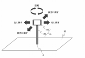
- FIG. 2 is a schematic diagram illustrating an example of movement information of the assisting tool accompanying the movement of the person in Embodiment 1 of the present invention.
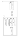
- FIG. 3 is a flowchart showing an example of the mobile object steering method according to the first embodiment of the present invention.
- FIG. 4 is a block diagram illustrating an example of a steering signal transmission system according to Embodiment 1 of the present invention.
- FIG. 5 is a block diagram illustrating an example of a mobile control system according to Embodiment 2 of the present invention.
- FIG. 6 is a block diagram illustrating an example of a steering signal transmission system according to Embodiment 2 of the present invention.
- FIG. 1 is a block diagram illustrating an example of a mobile control system according to Embodiment 1 of the present invention.
- FIG. 2 is a schematic diagram illustrating an example of movement information of the assisting tool accompanying
- FIG. 7 is a flowchart showing an example of a mobile object steering method according to Embodiment 2 of the present invention.
- FIG. 8 is a block diagram illustrating an example of a mobile control system according to Embodiment 3 of the present invention.
- FIG. 9 is a schematic diagram illustrating an example of human motion information according to Embodiment 3 of the present invention.
- FIG. 10 is a flowchart showing an example of a mobile object steering method according to Embodiment 3 of the present invention.
- FIG. 11 is a block diagram illustrating an example of a mobile control system according to Embodiment 4 of the present invention.
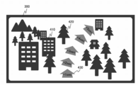
- FIG. 12 is a schematic diagram illustrating an example of a display screen according to the fourth embodiment of the present invention.
- FIG. 13 is a flowchart showing an example of a mobile object steering method according to Embodiment 4 of the present invention.
- the movement information of the auxiliary tool accompanying the movement of the person uses the auxiliary tool at a predetermined position as a reference point, and the person reproduces the movement of the moving body by his / her own body. It is the movement information of the assisting tool accompanying.
- the auxiliary tool is connected to a support body in which at least one point is fixed, and is movable with the fixed point in the support body as a reference point.
- the mobile object is a flying object.
- the flying object is a drone.
- the movement information of the auxiliary tool accompanying the movement of the person includes the type of movement and the degree of movement
- the movement information of the moving body includes the type of movement and the movement.
- the steering signal information includes the type of movement to be instructed and the degree of movement to be instructed.
- control signal transmitter further includes voice information acquisition means for acquiring human voice information, and the conversion means uses the acquired voice information based on the conversion information.
- the conversion information further includes human voice information, and the voice information and the control signal information are associated with each other.
- the mobile body further includes image information acquisition means for acquiring image information, and image information transmission means for transmitting the acquired image information to the steering signal transmitter.
- the steering signal transmitter further includes image information receiving means for receiving image information transmitted from the moving body, and display means for displaying the image information.
- the image information acquisition means of the mobile body is a camera.
- the display means of the control signal transmitter is a wearable display for a person.
- the mobile object steering system includes, for example, a position predicting unit that predicts the position of the mobile object after a predetermined time based on the image information received by the image information receiving unit.
- the display means displays the image information received by the image information receiving means and the predicted position information obtained by the position prediction means.
- the movement information of the auxiliary tool accompanying the movement of the person uses the auxiliary tool at a predetermined position as a reference point, and the person reproduces the movement of the moving body by his / her own body. It is the movement information of the assisting tool accompanying.
- the auxiliary tool is connected to a support body at which at least one point is fixed, and is movable with the fixed point on the support body as a reference point.
- the moving body is a flying body.
- the flying object is a drone.
- the movement information of the auxiliary tool accompanying the movement of the person includes the type of movement and the degree of movement
- the movement information of the moving object includes the type of movement and the movement.
- the steering signal information includes the type of movement to be instructed and the degree of movement to be instructed.
- the control signal transmission system of the present invention further includes, for example, voice information acquisition means for acquiring human voice information, and the conversion means sends the acquired voice information to the mobile body based on the conversion information.
- the conversion information further includes human voice information, and is associated with the voice information and the steering signal information.
- the steering signal transmission system of the present invention further includes, for example, image information receiving means for receiving image information transmitted from the moving body, and display means for displaying the image information.
- the display means is a wearable display for a person.
- the control signal transmission system of the present invention includes, for example, an information acquisition terminal and a server, and the terminal and the server can be connected via a communication network, and the terminal transmits the operation information acquisition means.
- the server includes the storage unit, the conversion unit, and the signal transmission unit.
- the information acquisition terminal further includes the voice information acquisition means.
- the steering signal transmission system of the present invention further includes, for example, a display terminal, and the display terminal includes the image information receiving means and the display means.
- the steering signal transmission system of the present invention further includes, for example, a position prediction unit that predicts a position of the moving body after a predetermined time based on image information received by the image information reception unit, and the display unit includes The image information received by the image information receiving means and the predicted position information obtained by the position predicting means are displayed.
- the movement information of the auxiliary tool accompanying the movement of the person uses the auxiliary tool at a predetermined position as a reference point, and the person reproduces the movement of the moving body by his / her own body. It is the movement information of the assisting tool accompanying.
- the auxiliary tool is connected to a support body in which at least one point is fixed, and is movable with the fixed point in the support body as a reference point.
- the moving body is a flying body.
- the flying object is a drone.
- the movement information of the auxiliary tool accompanying the movement of the person includes the type of movement and the degree of movement
- the movement information of the moving body includes the type of movement and the movement.
- the steering signal information includes the type of movement to be instructed and the degree of movement to be instructed.
- the mobile control method of the present invention further includes, for example, a voice information acquisition step of acquiring human voice information by the system, and in the conversion step, the acquired voice information is based on the conversion information. It converts into the steering signal to a moving body, and the conversion information further includes human voice information, and the voice information and the steering signal information are associated with each other.
- the moving body maneuvering method of the present invention further includes, for example, an image information acquiring step of acquiring image information by the moving body, an image information transmitting step of transmitting the acquired image information to the system by the moving body,
- the system includes an image information receiving process in which the system receives image information transmitted from the mobile body, and a display process in which the system displays the image information.
- image information is acquired by a camera in the image information acquisition step.
- the image information is displayed on a wearable display for a person.
- the mobile object steering method of the present invention further includes, for example, a position prediction step of predicting the position of the mobile object after a predetermined time based on the image information received in the image information reception step by the system.
- a position prediction step of predicting the position of the mobile object after a predetermined time based on the image information received in the image information reception step by the system.
- the display step the image information received in the image information reception step and the predicted position information obtained in the position prediction step are displayed.
- Embodiment 1 relates to a mobile control system, a control signal transmission system, and a mobile control method of the present invention.
- FIG. 1 shows a block diagram of a mobile control system according to this embodiment.
- the mobile control system 1 of this embodiment includes a control signal transmitter 10 and a mobile body 20, and the control signal transmitter 10 and the mobile body 20 are connected via a communication network. Is possible.
- the moving body 20 is, for example, an unmanned aerial vehicle operated by remote control, and includes a flying body.
- the flying object include a rotary wing drone such as a helicopter.
- An example of the helicopter is a multicopter such as a quadricoptoer, and a specific example of the multicopter such as the four-wing type is a so-called drone.
- Other examples of the flying object include a wirelessly operated flying object such as a balloon, an airship, a variable wing (VTOL), a fixed wing, and a plurality of wings (for example, Amazon Air).
- examples of the moving body include a throttle car type remote machine.
- the moving body 20 includes signal receiving means 201.
- the signal receiving unit 201 is, for example, a central processing unit (CPU).
- the steering signal transmitter 10 is the auxiliary tool, and the auxiliary tool (that is, the steering signal transmitter 10) includes the storage unit 101, the operation information acquisition unit 102, the conversion unit 103, and the signal transmission unit 104.
- the steering signal transmitter 10 is, for example, an apparatus (terminal) that integrally includes the auxiliary tool, the storage unit 101, the operation information acquisition unit 102, the conversion unit 103, and the signal transmission unit 104, and the system But you can.
- the steering signal transmitter 10 as the auxiliary tool includes the storage means 101, the operation information acquisition means 102, the conversion means 103, and the signal transmission means 104 as described above.
- the conversion unit 103 and the signal transmission unit 104 may be incorporated in, for example, data processing unit (data processing apparatus) that is hardware, or may be software or hardware in which the software is incorporated.
- the data processing means may include a central processing unit (CPU).
- CPU central processing unit
- the storage unit 101 and the motion information acquisition unit 102 are electrically connected to the conversion unit 103, and the conversion unit 103 is further electrically connected to the signal transmission unit 104. ing.
- any one or more means may be separated.
- the auxiliary tool (that is, the steering signal transmitter 10 in the present embodiment) is, for example, a terminal, and specific examples include a mobile phone, a smartphone, a tablet, and the like.
- Storage means 101 includes conversion information. Examples of the storage means 101 include a random access memory (RAM), a read only memory (ROM), a flash memory, a hard disk (HD), an optical disk, a floppy (registered trademark) disk (FD), and the like.
- the storage unit 101 may be a device built-in type or an external type such as an external storage device.
- the movement information acquisition unit 102 acquires movement information of the auxiliary tool accompanying the driver's movement with the auxiliary tool at a predetermined position as a reference point.
- the motion information acquisition unit 102 is, for example, a sensor that is mounted on the assisting tool itself and detects the movement of the assisting tool. Examples of the sensor include a gyro sensor and an acceleration sensor.
- the type of motion information obtained by the motion information acquisition unit 102 is not particularly limited, and examples thereof include information on movement of the auxiliary tool in two or three dimensions using a predetermined point as a reference point.
- the auxiliary tool is preferably connected to a support, for example.
- at least one point is fixed to the support, for example, on the ground, and the auxiliary tool connected to the support is, for example, a fixed point on the support. It is preferable that it is movable. With such a configuration, it is possible to easily obtain the movement information of the assisting tool accompanying the operation of the operator using the fixed point as a reference point.
- the conversion information includes the movement information of the auxiliary tool accompanying the movement of the person and the steering signal information for instructing the movement of the moving body to the moving body, which are associated with each other.
- the movement information of the auxiliary tool accompanying the movement of the person is the movement information of the auxiliary tool accompanying the movement of the person who imagines the movement of the moving body with the auxiliary tool at the predetermined position as a reference point. It is the movement information of the auxiliary tool accompanying the operation
- the movement information of the auxiliary tool accompanying the movement of the person includes, for example, the type of movement, and the movement information of the moving body includes, for example, the type of movement.
- the conversion information will be described by taking a case where the mobile body is a flying body such as a drone as a specific example.
- the drone controls the motors of the propellers with the two sticks of the pilot.
- the movement of the drone such as forward / backward / left / right progression, turning, and stopping is controlled by the movement of the motor (throttle, pitch, roll, ladder, etc.). That is, the operation of the pilot in the conventional drone maneuvering is the operation of the finger that operates the pilot machine.
- a person cannot fly using that body.
- a person has a common potential image regarding operations (eg, posture, pose, etc.) when flying using the body from movies, picture books, comics, animations, and the like.
- the movement information of the assisting tool accompanying the imaged person's movement is associated with the control signal that instructs the drone to move the corresponding drone.
- the pilot can take a motion that is imaged with an auxiliary tool, and the motion is converted into associated steering signal information. Therefore, the drone can be operated more easily than the operation of the pilot. It becomes possible.
- a conventional pilot for example, it is necessary to memorize subtle movements and combinations of movements of two sticks, which is extremely difficult to operate.
- the operation related to is easy to memorize for the operator, and even when it is necessary to make a quick judgment, the body easily reacts naturally and the operation becomes easier.
- the combination of the movement information of the auxiliary tool accompanying the movement of the person and the movement of the moving body related thereto is not particularly limited, and can be set as appropriate according to the attribute of the operator, for example.
- Examples of the attribute include children, adults, women, men, beginners, and experienced people.
- the conversion information can be obtained, for example, by systematizing the movement of the moving body and the operation image in a state having auxiliary tools common to predetermined attributes.
- auxiliary tools common to predetermined attributes As a specific example, for example, when the attribute is a child, for each movement of the moving object, potential action images in a plurality of children are collected, a common action image is selected, and each movement of the moving object is associated with it.
- the conversion information can be set by organizing the operation image to be performed.
- FIG. 2 illustrates the relationship between the movement information of the auxiliary tool accompanying the movement of the person and the movement of the moving body related thereto.
- the steering signal transmitter 10 includes an auxiliary tool 110 and a support 120
- the auxiliary tool 110 includes a storage unit 101, an operation information acquisition unit 102, a conversion unit 103, and a signal transmission unit 104.
- the auxiliary tool 110 is a smartphone.
- the person who operates the auxiliary tool 2 stands in front of the page and faces the other side of the page.
- the auxiliary tool 110 is rotatably connected to the other end of a rod-like support 120 having one end Q fixed to the ground 30. As shown in FIG.
- auxiliary tool 110 can be tilted or rotated in the front-rear direction and the left-right direction.
- FIG. 2 for example, a state where the operator holding the auxiliary tool 110 tilts the auxiliary tool 110 backward corresponds to the forward movement of the moving body, and the state where the auxiliary tool 110 is tilted forward is shown.
- the state where the auxiliary tool 110 is tilted to the right corresponds to the right turn of the moving body
- the state where the auxiliary tool 110 is tilted to the left corresponds to the left turn of the moving body.
- “rear / front” as the direction in which the assisting tool 10 is tilted refers to the driver side as the front and the side opposite to the driver as the rear, with the assisting tool 110 as a reference.
- the rear of the auxiliary tool 110 may be referred to as the front for the pilot
- the front of the auxiliary tool 10 may be referred to as the rear for the pilot.
- the movement information of the auxiliary tool accompanying the movement of the person includes, for example, the degree of movement in addition to the type of movement
- the movement information of the moving object includes, for example, the movement type in addition to the movement type.
- the control signal information includes the type of movement to be instructed and the degree of movement to be instructed. That is, it is preferable to associate the weight of the movement of the moving body with the weight of the movement of the moving object by weighting the degree of movement of the assisting device accompanying the movement of the person. Thereby, it is possible to control not only the type of movement but also the magnitude and speed of movement, for example.
- the auxiliary tool 110 when the auxiliary tool 110 is tilted backward to advance the moving body, the moving body can be advanced at a faster speed by tilting the auxiliary tool 110 further backward.
- the conversion means 103 converts the acquired operation information into a steering signal for the moving body based on the conversion information.
- An example of the conversion unit 103 is the CPU.
- the signal transmission means 104 transmits the steering signal to the moving body.
- An example of the signal transmission means 104 is the CPU.
- the moving body 20 has a signal receiving unit 201, and the signal receiving unit 201 receives a steering signal from the steering signal transmitter 10.
- An example of the signal receiving means 201 is the CPU.
- the moving body 20 is not particularly limited, and examples thereof include a flying body such as a drone.
- FIG. 3 shows a flowchart of the moving object maneuvering method in the present embodiment.
- the mobile body steering method of this embodiment is implemented as follows, for example using the mobile body steering system of FIG.
- the mobile control method of this embodiment includes an A1 step (acquisition of motion information), an A2 step (signal conversion), an A3 step (signal transmission), and an A4 step (signal reception).
- the conversion information is prepared prior to the A1 step.
- the conversion information for example, the conversion information corresponding to the attributes of the driver can be selected as described above.
- step A1 Acquisition of motion information
- the motion information of the assisting tool accompanying the operation of the pilot is acquired by detecting the motion of the assisting tool accompanying the operation of the pilot.
- A2 step the operation information is converted into a steering signal for the moving body based on the conversion information.
- (A3) Signal Transmission In the A3 step, the converted steering signal is transmitted from the steering signal transmitter 10 to the moving body 20.
- A4 Signal Reception
- the moving body 20 receives the control signal from the control signal transmitter 10. The movement of the moving body 20 is controlled according to the steering signal.
- the movement information of the auxiliary tool accompanying the movement of the person with the image of the movement of the moving body using the auxiliary tool at a predetermined position as a reference point. Since it is converted into a steering signal for the moving body and the moving body is steered, simpler maneuvering is possible. These effects are the same in the embodiments described later.
- the control signal transmitter 10 is not limited to the form of one terminal (auxiliary tool) as described above, and may be, for example, a system. As a specific example, two independent terminals are provided. It may be in a form connectable via a communication line network. In this case, for example, one terminal is the auxiliary device including the operation information acquisition unit 102, and the other terminal includes the storage unit 101, the conversion unit 103, and the signal transmission unit 104. An example of this form is shown in FIG.
- FIG. 4 shows an example in which the control signal transmitter 10 is a control signal transmission system, and shows a block diagram of the system.
- the control signal transmission system 10 includes a main body 11 and a terminal 12, and the main body 11 and the terminal 12 can be connected via a wired or wireless communication line network.
- the main body 11 includes a storage unit 101, a conversion unit 103, and a signal transmission unit 104.
- the storage unit 101 is electrically connected to the conversion unit 103
- the conversion unit 103 is further electrically connected to the signal transmission unit 104.
- the terminal 12 is an information acquisition terminal, that is, the auxiliary tool, and includes operation information acquisition means 102.
- the terminal itself that is an auxiliary tool includes the operation information acquisition unit 102 that detects the movement of the terminal.
- the auxiliary tool and the operation information acquisition unit include It may be a separate terminal.
- the motion information acquisition means includes, for example, a sensor that detects the movement of the terminal (auxiliary tool) 12 from the outside. Examples of the sensor include motion capture such as KINECT (registered trademark) manufactured by Microsoft Corporation and Perception Neuron manufactured by noisytom Corporation.
- the type of motion information obtained by the motion information acquisition unit 102 is not particularly limited. For example, a motion image such as a 2D or 3D image, a 2D or 3D motion acquired by the sensor or the like. Examples include motion analysis data analyzed by sensor data, a motion analysis table, and the like.
- the motion information acquisition means 102 may acquire, for example, information around the assisting tool, that is, for example, the motion information of the driver, in addition to the motion information of the assisting tool accompanying the motion of the driver.
- the movement information of the driver can be added to the movement information of the auxiliary tool accompanying the movement of the person.
- the second embodiment further relates to a form including voice information acquisition means and a voice information acquisition step.
- the description of the first embodiment can be used.
- FIG. 5 shows a block diagram of the mobile control system in the present embodiment.
- the mobile control system 1 of the present embodiment has a configuration in which the control signal transmitter 10 as an auxiliary tool further includes a voice information acquisition unit 105.
- the steering signal transmitter 10 may be a steering signal transmission system as described above.
- FIG. 6 shows a block diagram of the system.
- the steering signal transmission system 10 includes a main body 11 and a terminal 12, and the main body 11 and the terminal 12 can be connected via a wired or wireless communication line network.
- the main body 11 includes a storage unit 101, a conversion unit 103, and a signal transmission unit 104.
- the storage unit 101 is electrically connected to the conversion unit 103
- the conversion unit 103 is further electrically connected to the signal transmission unit 104.
- the terminal 12 is an information acquisition terminal, that is, the auxiliary tool, and includes operation information acquisition means 102 and audio information acquisition means 105.
- the operation information acquisition unit 102 and the voice information acquisition unit 105 may be separate terminals, and may be connectable to the main body 11 via the communication line network.
- the voice information acquisition means 105 acquires the voice information of the pilot.
- the voice information acquisition means is, for example, the terminal 12 as described above, and a specific example is a voice recognition device such as a microphone.
- the type of voice information obtained by the voice information acquisition unit 105 is not particularly limited, and may be voice data, voice analysis data analyzed by a voice analysis table, or the like.
- the conversion information in the storage means 101 further includes human voice information, and is associated with the voice information and the steering signal information.
- the audio information include audio information indicating the type of operation, audio information indicating the degree of operation, and the like.
- Examples of the voice information indicating the type of the former operation include information indicating a stop instruction to the moving body such as “dangerous” and “stop”.
- As the voice information indicating the degree of the latter operation for example, information indicating an indication of the magnitude of movement to the moving body such as “little” or “large”, or moving body such as “fast” or “slow” Information indicating an indication of the speed of movement of the user.
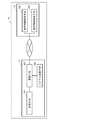
- FIG. 7 shows a flowchart of the mobile object steering method in the present embodiment.
- the mobile body steering method of this embodiment is implemented as follows using the mobile body steering system of FIG. 5, for example.
- the mobile control method of the present embodiment includes an A1 step (motion information acquisition), an A1 ′ step (voice information acquisition), an A2 step (signal conversion), an A3 step (signal transmission), and A4. Includes steps (signal reception).
- the conversion information is prepared prior to the A1 step.
- the conversion information for example, the conversion information corresponding to the attributes of the driver can be selected as described above.
- step A1 Acquisition of motion information
- the motion information of the assisting tool accompanying the operation of the pilot is acquired by detecting the motion of the assisting tool accompanying the operation of the pilot.
- (A3) Signal Transmission In the A3 step, the converted steering signal is transmitted from the steering signal transmitter 10 to the moving body 20.
- A4 Signal Reception
- the moving body 20 receives the control signal from the control signal transmitter 10. The movement of the moving body 20 is controlled according to the steering signal.
- the voice information of the driver is further converted into a steering signal for the mobile body, and the mobile body is steered. It is also possible to give an instruction of a quick movement or an instruction of a quick movement.
- the third embodiment further relates to a form including an image information receiving unit and a display unit, and an image information receiving step and a display step.
- the description of Embodiment 1 and Embodiment 2 can be used.
- FIG. 8 shows a block diagram of the mobile control system in the present embodiment.
- the steering signal transmitter 10 further includes an image information receiving means 106 and a display means 107
- the moving body 20 further includes an image information acquisition means. 202 and image information transmission means 203.
- the image information acquisition unit 202 acquires image information.
- the image information is, for example, a moving image (video).
- the image information acquisition unit 202 is, for example, a camera and is mounted on the main body of the moving body 20.
- An example of the camera is a camera that captures one direction.
- An example of the camera is a camera whose shooting direction is one direction, and the camera may be capable of rotating 360 °.
- the camera is mounted on the moving body 20 in a state of photographing the front direction.
- the camera may be, for example, a 360 ° camera that captures all directions at the same time. In the case of a 360 ° camera, for example, an omnidirectional image can be acquired without rotating the camera.
- the image information transmitting unit 203 transmits the image information acquired by the image information acquiring unit 202 to the steering signal transmitter 10.
- Examples of the image information transmitting unit 203 include a CPU.
- the image information receiving unit 106 receives the image information transmitted from the moving body 20.
- Examples of the image information receiving unit 106 include a CPU.
- Display means 107 displays the received image information.
- the display means 107 includes, for example, a monitor that outputs video, and specific examples include various image display devices such as a liquid crystal display (LCD) and a cathode ray tube (CRT) display.
- the display means may be, for example, display means included in the auxiliary tool.
- examples of the terminal 13 having the display unit 107 include the auxiliary tools such as a smartphone and a tablet as described above.
- the terminal 13 having the display means 107 may be, for example, a human-mountable display or the like, and may be a head-mounted display or the like as a specific example.
- the display means 107 is the wearable display, for example, the display means 107 is a motion information acquisition means (hereinafter referred to as “motion information acquisition means”) that acquires the movement information of the driver, separately from the motion information acquisition means 102 that acquires the movement information of the auxiliary device. , Also referred to as second operation information acquisition means).
- the second motion information acquisition means acquires, for example, the motion of the face of the operator wearing the same as the motion information of the person.
- the display means 107 is the wearable display and the image information acquisition means 202 is a camera that captures one direction, for example, the moving direction of the moving object and the direction of the image displayed on the display means 107 are the same. It is preferable that When the display unit 107 also serves as the second motion information acquisition unit, for example, the movement of the display unit 107 by the operator and the direction of the camera in the moving body 20 can be linked. For this reason, for example, the direction of the operator's face (direction of view) and the direction of the camera can be linked.
- FIG. 9 illustrates the relationship between the motion information of the person and the motion of the camera in the moving body 20 related thereto.
- FIG. 9 is an example, and the present invention is not limited to this. As shown in FIG.
- the storage means may further include human motion information as the conversion information.
- the human motion information is, for example, information on the movement of a person with a predetermined direction as a reference point, and specifically, movement information on the face direction with the face of a person facing the front as a reference point. It is.
- the conversion information is associated with the human movement information (for example, the orientation of the face), for example, with steering signal information for instructing the moving body of the moving body.
- the motion information acquisition means (auxiliary tool) 102 shown in FIG. 2 is combined with the second motion information acquisition means (wearable display) will be described as an example. The operator wears the second motion information acquisition means (wearable display) and performs the steering while holding the auxiliary tool.
- the pilot can move the moving body forward by turning the face forward and tilting the terminal 12 backward, moving by moving the face upward and tilting the terminal 12 backward.
- the body can be raised, and the operator can turn the mobile body to the right by turning the face forward and tilting the terminal 12 to the right, turning the face to the right, and turning the terminal 12 By moving it to the right, the moving body can be moved horizontally to the right.
- FIG. 10 shows a flowchart of the mobile object steering method in the present embodiment.
- the mobile body steering method of this embodiment is implemented as follows, for example using the mobile body steering system of FIG.
- the mobile control method of the present embodiment includes an A1 step (motion information acquisition), an A2 step (signal conversion), an A3 step (signal transmission), an A4 step (signal reception), and a B1 step.
- A1 step motion information acquisition
- A2 step signal conversion
- an A3 step signal transmission
- A4 step signal reception
- B1 step image information acquisition
- B2 step image information transmission
- B3 step image information reception
- B4 step image information display
- the A1 step to the A4 step are the same as those in the above-described embodiment, and the B1 step to the B4 step are performed in parallel with this.
- control signal transmitter 10 receives the image information transmitted from the moving body 20.
- the fourth embodiment further relates to a form in which the future predicted position of the mobile object is displayed on the display means, and specifically relates to a form including a position prediction means and a position prediction step.
- This embodiment is the same as the third embodiment unless otherwise indicated, and the description of the first, second, and third embodiments can be incorporated.
- FIG. 11 shows a block diagram of the mobile control system in the present embodiment.
- the mobile control system 1 according to the present embodiment has a configuration in which the control signal transmitter 10 further includes a position predicting unit 108.
- the steering signal transmitter 10 may be a steering signal transmission system as described above.
- the steering signal transmission system 10 includes a main body 11 and two terminals 12 and 13 as described above.
- the position prediction unit 108 may be further included in the terminal 13 including the image information reception unit 106 and the display unit 107.
- the position predicting means 108 predicts the future position of the moving body 20 based on the image information transmitted from the moving body 20 received by the image information receiving means 106.
- the predicted position information obtained by the prediction may be, for example, position information after a predetermined time or position information with time.
- An example of the position predicting unit 108 is a CPU.
- the display means 107 displays the received image information, and further displays the predicted future position of the mobile object 20 predicted by the position prediction means 108.
- the display means 107 includes, for example, a monitor that outputs video, and specific examples include various image display devices such as a liquid crystal display (LCD) and a cathode ray tube (CRT) display.
- the display means may be, for example, display means included in the auxiliary tool.
- examples of the terminal 13 having the display unit 107 include the auxiliary tools such as a smartphone and a tablet as described above.
- the terminal 13 having the display unit 107 may be, for example, a wearable display for humans, and may be a head mounted display or the like as a specific example. When the display unit 107 is the wearable display, for example, the display unit 107 may also serve as the operation information acquisition unit 102.
- FIG. 12 shows an example of a display screen on the display means 107.
- FIG. 12 is an example, and the present invention is not limited to this.
- the display unit 107 displays a building 410, a tree 420, and the like as the image information received from the moving body 20 on the display screen 300.
- the predicted position information of the moving body 20 predicted by the position prediction means 108 is displayed.
- temporal position information is displayed as the predicted position information.
- the predicted position information can indicate a position up to a predetermined time (for example, after 5 seconds) in a predetermined time unit (for example, every second).
- FIG. 13 shows a flowchart of the mobile object steering method in the present embodiment.
- the mobile body steering method of this embodiment is implemented as follows, for example using the mobile body steering system of FIG.
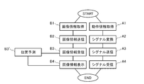
- the mobile control method of the present embodiment includes an A1 step (motion information acquisition), an A2 step (signal conversion), an A3 step (signal transmission), an A4 step (signal reception), and a B1 step.
- A1 step motion information acquisition
- A2 step signal conversion
- an A3 step signal transmission
- A4 step signal reception
- B1 step image information acquisition
- B2 step image information transmission
- B3 step image information reception
- B3 ′ step position prediction
- B4 step image information display
- the A1 step to the A4 step are the same as those in the above-described embodiment, and the B1 step to the B4 step are performed in parallel with this.
- control signal transmitter 10 receives the image information transmitted from the moving body 20.
- (B4) Image information display In the B4 step, the image information received by the control signal transmitter 10 and the predicted position information are displayed.
- the program according to the present embodiment is a program capable of executing the above-described mobile body steering method on a computer.
- the program of this embodiment may be recorded on a computer-readable recording medium, for example.
- the recording medium is not particularly limited, and examples thereof include a random access memory (RAM), a read-only memory (ROM), a hard disk (HD), an optical disk, and a floppy (registered trademark) disk (FD).
Landscapes
- Engineering & Computer Science (AREA)
- Physics & Mathematics (AREA)
- Aviation & Aerospace Engineering (AREA)
- Automation & Control Theory (AREA)
- Radar, Positioning & Navigation (AREA)
- Remote Sensing (AREA)
- General Physics & Mathematics (AREA)
- Theoretical Computer Science (AREA)
- Mathematical Physics (AREA)
- Computing Systems (AREA)
- Control Of Position, Course, Altitude, Or Attitude Of Moving Bodies (AREA)
- Toys (AREA)
- User Interface Of Digital Computer (AREA)
- Selective Calling Equipment (AREA)
Abstract
本発明は、より簡便な移動体の操縦を可能にする新たなシステムを提供する。 本発明の移動体操縦システムは、移動体と移動体に対する操縦シグナル送信機とを含む。前記移動体は、前記操縦シグナル送信機からの操縦シグナルを受信するシグナル受信手段を有する。前記操縦シグナル送信機は、補助具、変換情報を含む記憶手段、所定位置の補助具を基準点とする、操縦者の動作に伴う補助具の動き情報を取得する動作情報取得手段、取得した動作情報を、前記変換情報に基づいて、移動体への操縦シグナルに変換する変換手段、および、前記操縦シグナルを前記移動体に送信するシグナル送信手段を含む。前記変換情報は、人の動作に伴う補助具の動き情報と、前記移動体の動きを前記移動体に指示する操縦シグナル情報とを含み、それぞれが関連付けられており、前記人の動作に伴う補助具の動き情報は、所定位置の補助具を基準点とする、前記移動体の動きをイメージした人の動作に伴う補助具の動き情報であることを特徴とする。
Description
本発明は、移動体操縦システム、操縦シグナル送信システム、移動体操縦方法、プログラム、および記録媒体に関する。
遠隔操作で操縦する無人機の中でも、ドローンは、近年、様々なサービスへの利用が試みられている。また、一般家庭用のおもちゃとしても、入手が容易となってきている。ドローンの操縦は、いわゆるプロポーショナル式の操縦機が使用され、前記操縦機に装着されている2本のスティックを動かすことで、ドローンのモーターを制御し、これによってドローンの動きを制御している(非特許文献1)。しかしながら、ドローンの操縦は、極めて難しく、安全に操縦するには、十分な練習をつまなければならないのが実情である。
"Scalable Autonomy Concept for Reconnaissance UAVs on the Basis of an HTN Agent Architecture", 2016 International Conference on Unmanned Aircraft Systems (ICUAS), June 7-10, 2016.
そこで、本発明は、ドローン等の遠隔操作で操縦する無人機を、より簡便に操縦するための新たなシステムの提供を目的とする。
前記目的を達成するために、本発明の移動体操縦システムは、
移動体と前記移動体に対する操縦シグナル送信機とを含み、
前記移動体は、
前記操縦シグナル送信機からの操縦シグナルを受信するシグナル受信手段を有し、
前記操縦シグナル送信機は、
補助具、
変換情報を含む記憶手段、
所定位置の補助具を基準点とする、操縦者の動作に伴う補助具の動き情報を取得する動作情報取得手段、
取得した動作情報を、前記変換情報に基づいて、前記移動体への操縦シグナルに変換する変換手段、および、
前記操縦シグナルを前記移動体に送信するシグナル送信手段を含み、
前記変換情報は、
人の動作に伴う補助具の動き情報と、前記移動体の動きを前記移動体に指示する操縦シグナル情報とを含み、それぞれが関連付けられており、
前記人の動作に伴う補助具の動き情報は、
所定位置の補助具を基準点とする、前記移動体の動きをイメージした人の動作に伴う補助具の動き情報であることを特徴とする。
移動体と前記移動体に対する操縦シグナル送信機とを含み、
前記移動体は、
前記操縦シグナル送信機からの操縦シグナルを受信するシグナル受信手段を有し、
前記操縦シグナル送信機は、
補助具、
変換情報を含む記憶手段、
所定位置の補助具を基準点とする、操縦者の動作に伴う補助具の動き情報を取得する動作情報取得手段、
取得した動作情報を、前記変換情報に基づいて、前記移動体への操縦シグナルに変換する変換手段、および、
前記操縦シグナルを前記移動体に送信するシグナル送信手段を含み、
前記変換情報は、
人の動作に伴う補助具の動き情報と、前記移動体の動きを前記移動体に指示する操縦シグナル情報とを含み、それぞれが関連付けられており、
前記人の動作に伴う補助具の動き情報は、
所定位置の補助具を基準点とする、前記移動体の動きをイメージした人の動作に伴う補助具の動き情報であることを特徴とする。
本発明の操縦シグナル送信システムは、移動体に対する操縦シグナル送信システムであり、
補助具、
変換情報を含む記憶手段、
所定位置の補助具を基準点とする、操縦者の動作に伴う補助具の動き情報を取得する動作情報取得手段、
取得した動作情報を、変換情報に基づいて、移動体への操縦シグナルに変換する変換手段、および、
前記操縦シグナルを前記移動体に送信するシグナル送信手段を含み、
前記変換情報は、
人の動作に伴う補助具の動き情報と、移動体の動き情報と、前記移動体の動きを前記移動体に指示する操縦シグナル情報とを含み、それぞれが関連付けられており、
前記人の動作に伴う補助具の動き情報は、
所定の位置の補助具を基準点とする、前記移動体の動きをイメージした人の動作に伴う補助具の動き情報であることを特徴とする。
補助具、
変換情報を含む記憶手段、
所定位置の補助具を基準点とする、操縦者の動作に伴う補助具の動き情報を取得する動作情報取得手段、
取得した動作情報を、変換情報に基づいて、移動体への操縦シグナルに変換する変換手段、および、
前記操縦シグナルを前記移動体に送信するシグナル送信手段を含み、
前記変換情報は、
人の動作に伴う補助具の動き情報と、移動体の動き情報と、前記移動体の動きを前記移動体に指示する操縦シグナル情報とを含み、それぞれが関連付けられており、
前記人の動作に伴う補助具の動き情報は、
所定の位置の補助具を基準点とする、前記移動体の動きをイメージした人の動作に伴う補助具の動き情報であることを特徴とする。
本発明の移動体操縦方法は、
移動体と、前記本発明の操縦シグナル送信システムを使用し、
前記システムにより、所定位置の補助具を基準点とする、操縦者の動作に伴う補助具の動き情報を取得する動作情報取得工程、
前記システムにより、取得した動作情報を、変換情報に基づいて、前記移動体への操縦シグナルに変換する変換工程、
前記システムにより、前記操縦シグナルを前記移動体に送信するシグナル送信工程、および、
前記送信された前記操縦シグナルを前記移動体が受信するシグナル受信工程を含み、
前記変換情報は、
人の動作に伴う補助具の動き情報と、前記移動体の動きを前記移動体に指示する操縦シグナル情報とを含み、それぞれが関連付けられており、
前記人の動作に伴う補助具の動き情報は、
所定位置の補助具を基準点とする、前記移動体の動きをイメージした人の動作に伴う補助具の動き情報であることを特徴とする。
移動体と、前記本発明の操縦シグナル送信システムを使用し、
前記システムにより、所定位置の補助具を基準点とする、操縦者の動作に伴う補助具の動き情報を取得する動作情報取得工程、
前記システムにより、取得した動作情報を、変換情報に基づいて、前記移動体への操縦シグナルに変換する変換工程、
前記システムにより、前記操縦シグナルを前記移動体に送信するシグナル送信工程、および、
前記送信された前記操縦シグナルを前記移動体が受信するシグナル受信工程を含み、
前記変換情報は、
人の動作に伴う補助具の動き情報と、前記移動体の動きを前記移動体に指示する操縦シグナル情報とを含み、それぞれが関連付けられており、
前記人の動作に伴う補助具の動き情報は、
所定位置の補助具を基準点とする、前記移動体の動きをイメージした人の動作に伴う補助具の動き情報であることを特徴とする。
本発明のプログラムは、前記本発明の移動体操縦方法をコンピュータ上で実行可能なことを特徴とする。
本発明のコンピュータ読み取り可能な記録媒体は、前記本発明のプログラムを記録していることを特徴とする。
本発明によれば、移動体の簡便な操縦を実現できる。
本発明の移動体操縦システムは、例えば、前記人の動作に伴う補助具の動き情報は、所定位置の補助具を基準点とする、人が自身の身体により前記移動体の動きを再現する動作に伴う補助具の動き情報である。
本発明の移動体操縦システムは、例えば、前記補助具は、少なくとも一点が固定化された支持体と連結され、前記支持体における固定化された一点を基準点として、移動可能である。
本発明の移動体操縦システムは、例えば、前記移動体が、飛行体である。
本発明の移動体操縦システムは、例えば、前記飛行体が、ドローンである。
本発明の移動体操縦システムは、例えば、前記人の動作に伴う補助具の動き情報が、動きの種類と、動きの程度とを含み、前記移動体の動き情報が、動きの種類と、動きの程度とを含み、前記操縦シグナル情報が、指示する動きの種類と、指示する動きの程度とを含む。
本発明の移動体操縦システムは、例えば、前記操縦シグナル送信機は、さらに、人の声情報を取得する音声情報取得手段を含み、前記変換手段は、取得した音声情報を、前記変換情報に基づいて、前記移動体への操縦シグナルに変換し、前記変換情報は、さらに、人の音声情報を含み、前記音声情報と前記操縦シグナル情報とが関連付けられている。
本発明の移動体操縦システムは、例えば、前記移動体は、さらに、画像情報を取得する画像情報取得手段、および、前記取得した画像情報を、前記操縦シグナル送信機に送信する画像情報送信手段を有し、
前記操縦シグナル送信機は、さらに、前記移動体から送信された画像情報を受信する画像情報受信手段、および、前記画像情報を表示する表示手段を有する。
前記操縦シグナル送信機は、さらに、前記移動体から送信された画像情報を受信する画像情報受信手段、および、前記画像情報を表示する表示手段を有する。
本発明の移動体操縦システムは、例えば、前記移動体の画像情報取得手段が、カメラである。
本発明の移動体操縦システムは、例えば、前記操縦シグナル送信機の表示手段が、人への装着型ディスプレイである。
本発明の移動体操縦システムは、例えば、前記操縦シグナル送信機が、さらに、前記画像情報受信手段が受信した画像情報に基づいて、所定時間後の前記移動体の位置を予測する位置予測手段を有し、前記表示手段は、前記画像情報受信手段が受信した画像情報と、前記位置予測手段により得られた予測位置情報とを表示する。
本発明の操縦シグナル送信システムは、例えば、前記人の動作に伴う補助具の動き情報は、所定位置の補助具を基準点とする、人が自身の身体により前記移動体の動きを再現する動作に伴う補助具の動き情報である。
本発明の操縦シグナル送信システムは、例えば、前記補助具は、少なくとも一点が固定化された支持体と連結され、前記支持体における固定化された一点を基準点として、移動可能である。
本発明の操縦シグナル送信システムは、例えば、前記移動体が、飛行体である。
本発明の操縦シグナル送信システムは、例えば、前記飛行体が、ドローンである。
本発明の操縦シグナル送信システムは、例えば、前記人の動作に伴う補助具の動き情報が、動きの種類と、動きの程度とを含み、前記移動体の動き情報が、動きの種類と、動きの程度とを含み、前記操縦シグナル情報が、指示する動きの種類と、指示する動きの程度とを含む。
本発明の操縦シグナル送信システムは、例えば、さらに、人の声情報を取得する音声情報取得手段を含み、前記変換手段は、取得した音声情報を、前記変換情報に基づいて、前記移動体への操縦シグナルに変換し、前記変換情報は、さらに、人の音声情報を含み、前記音声情報と前記操縦シグナル情報と関連付けられている。
本発明の操縦シグナル送信システムは、例えば、さらに、前記移動体から送信される画像情報を受信する画像情報受信手段、および、前記画像情報を表示する表示手段を有する。
本発明の操縦シグナル送信システムは、例えば、前記表示手段が、人への装着型ディスプレイである。
本発明の操縦シグナル送信システムは、例えば、情報取得端末とサーバとを含み、前記端末と前記サーバとは、通信回線網を介して、接続可能であり、前記端末は、前記動作情報取得手段を含み、前記サーバは、前記記憶手段、前記変換手段および前記シグナル送信手段を含む。
本発明の操縦シグナル送信システムは、例えば、前記情報取得端末は、さらに、前記音声情報取得手段を含む。
本発明の操縦シグナル送信システムは、例えば、さらに、表示端末を含み、前記表示端末が、前記画像情報受信手段および前記表示手段を含む。
本発明の操縦シグナル送信システムは、例えば、さらに、前記画像情報受信手段が受信した画像情報に基づいて、所定時間後の前記移動体の位置を予測する位置予測手段を有し、前記表示手段は、前記画像情報受信手段が受信した画像情報と、前記位置予測手段により得られた予測位置情報とを表示する。
本発明の移動体操縦方法は、例えば、前記人の動作に伴う補助具の動き情報は、所定位置の補助具を基準点とする、人が自身の身体により前記移動体の動きを再現する動作に伴う補助具の動き情報である。
本発明の移動体操縦方法は、例えば、前記補助具は、少なくとも一点が固定化された支持体と連結され、前記支持体における固定化された一点を基準点として、移動可能である。
本発明の移動体操縦方法は、例えば、前記移動体が、飛行体である。
本発明の移動体操縦方法は、例えば、前記飛行体が、ドローンである。
本発明の移動体操縦方法は、例えば、前記人の動作に伴う補助具の動き情報が、動きの種類と、動きの程度とを含み、前記移動体の動き情報が、動きの種類と、動きの程度とを含み、前記操縦シグナル情報が、指示する動きの種類と、指示する動きの程度とを含む。
本発明の移動体操縦方法は、例えば、さらに、前記システムにより、人の声情報を取得する音声情報取得工程を含み、前記変換工程において、取得した音声情報を、前記変換情報に基づいて、前記移動体への操縦シグナルに変換し、前記変換情報は、さらに、人の音声情報を含み、前記音声情報と前記操縦シグナル情報とが関連付けられている。
本発明の移動体操縦方法は、例えば、さらに、前記移動体により、画像情報を取得する画像情報取得工程、前記移動体により、前記取得した画像情報を、前記システムに送信する画像情報送信工程、前記移動体から送信された画像情報を、前記システムが受信する画像情報受信工程、および、前記システムが前記画像情報を表示する表示工程を有する。
本発明の移動体操縦方法は、例えば、前記画像情報取得工程において、カメラにより画像情報を取得する。
本発明の移動体操縦方法は、例えば、前記表示工程において、人への装着型ディスプレイに前記画像情報を表示する。
本発明の移動体操縦方法は、例えば、さらに、前記システムにより、前記画像情報受信工程で受信した画像情報に基づいて、所定時間後の前記移動体の位置を予測する位置予測工程を有し、前記表示工程において、前記画像情報受信工程で受信した画像情報と、前記位置予測工程により得られた予測位置情報とを表示する。
つぎに、本発明の実施形態について、図を用いて説明する。本発明は、下記の実施形態によって何ら限定および制限されない。以下の各図において、同一部分には、同一符号を付している。各実施形態の説明は、特に言及がない限り、互いの説明を援用できる。さらに、各実施形態の構成は、特に言及がない限り、組合せ可能である。
[実施形態1]
実施形態1は、本発明の移動体操縦システム、操縦シグナル送信システムおよび移動体操縦方法に関する。
実施形態1は、本発明の移動体操縦システム、操縦シグナル送信システムおよび移動体操縦方法に関する。
図1に、本実施形態における移動体操縦システムのブロック図を示す。図1に示すように、本実施形態の移動体操縦システム1は、操縦シグナル送信機10と移動体20とを含み、操縦シグナル送信機10と移動体20とが、通信回線網を介して接続可能である。
移動体20は、例えば、遠隔操作により操縦される無人機であり、飛行体があげられる。前記飛行体は、例えば、ヘリコプター等の回転翼無人機があげられる。前記ヘリコプターは、例えば、四翼コプター(quadricoptoer)等のマルチコプターがあげられ、具体例として、前記四翼型等のマルチコプターは、例えば、いわゆるドローンがあげられる。前記飛行体としては、この他に、例えば、気球、飛行船、可変翼(VTOL)、固定翼、複数翼(例えば、Amazon Air等)等の無線操作の飛行体があげられる。また、前記移動体としては、例えば、スロットル自動車型の遠隔機等もあげられる。
移動体20は、シグナル受信手段201を含む。シグナル受信手段201は、例えば、中央演算装置(CPU)等である。
本実施形態において、操縦シグナル送信機10は、前記補助具であり、前記補助具(すなわち、操縦シグナル送信機10)が、記憶手段101、動作情報取得手段102、変換手段103およびシグナル送信手段104を有する。つまり、本実施形態において、操縦シグナル送信機10は、例えば、前記補助具、記憶手段101、動作情報取得手段102、変換手段103、シグナル送信手段104を一体として含む装置(端末)であり、システムでもよい。
前記補助具である操縦シグナル送信機10は、前述のように、記憶手段101、動作情報取得手段102、変換手段103、シグナル送信手段104を含む。変換手段103、およびシグナル送信手段104は、例えば、ハードウェアであるデータ処理手段(データ処理装置)に組み込まれてもよく、ソフトウェアまたは前記ソフトウェアが組み込まれたハードウェアでもよい。前記データ処理手段は、中央演算装置(CPU)等を備えてもよい。本実施形態の移動体操縦システム1において、記憶手段101、動作情報取得手段102は、変換手段103に、電気的に接続され、変換手段103は、さらにシグナル送信手段104に、電気的に接続されている。本実施形態の移動体操縦システム1は、例えば、いずれか1つ以上の手段が分離されてもよい。
前記補助具(すなわち、本実施形態における操縦シグナル送信機10)は、例えば、端末であり、具体例として、携帯電話、スマートフォン、タブレット等があげられる。
記憶手段101は、変換情報を含む。記憶手段101は、例えば、ランダムアクセスメモリ(RAM)、読み出し専用メモリ(ROM)、フラッシュメモリー、ハードディスク(HD)、光ディスク、フロッピー(登録商標)ディスク(FD)等があげられる。記憶手段101は、装置内蔵型でもよいし、外部記憶装置のような外付け型でもよい。
動作情報取得手段102は、所定位置の補助具を基準点とする、操縦者の動作に伴う補助具の動き情報を取得する。動作情報取得手段102は、例えば、前記補助具自体に搭載され、前記補助具の動きを検出するセンサである。前記センサとしては、例えば、ジャイロセンサ、加速度センサ等があげられる。
動作情報取得手段102により得られる動き情報の種類は、特に制限されず、例えば、所定の一点を基準点とする、2次元または3次元における前記補助具の移動の情報等があげられる。この場合、前記補助具は、例えば、支持体と連結されていることが好ましい。そして、前記支持体は、例えば、地面等に、少なくとも一点が固定化されており、且つ、前記支持体に連結された前記補助具は、例えば、前記支持体における固定化された一点を基準点として、移動可能であることが好ましい。このような形態であれば、前記固定化された一点を基準点として、操縦者の動作に伴う前記補助具の動き情報を容易に取得できる。
変換情報は、人の動作に伴う補助具の動き情報と、前記移動体の動きを前記移動体に指示する操縦シグナル情報とを含み、それぞれが関連付けられている。前記人の動作に伴う補助具の動き情報は、所定位置の補助具を基準点とする、前記移動体の動きをイメージした人の動作に伴う補助具の動き情報であり、例えば、所定位置の補助具を基準点とする、人が自身の身体により前記移動体の動きを再現する動作に伴う補助具の動き情報である。前記人の動作に伴う補助具の動き情報は、例えば、動きの種類を含み、前記移動体の動き情報は、例えば、動きの種類を含む。
前記変換情報について、具体例として、移動体がドローン等の飛行体である場合を例にあげて説明する。ドローンの操縦は、前述のように、操縦機の2本のスティックにより、各プロペラのモーターを制御している。そして、前記モーターの動き(スロットル、ピッチ、ロール、ラダー等)によって、前後左右への進行、旋回、停止等といったドローンの動きが制御されている。つまり、従来のドローンの操縦における操縦者の動作は、前記操縦機を操作する指の動作である。一方、人は、その身体を使って飛行することはできない。しかしながら、例えば、映画、絵本、コミック、アニメーション等から、身体を使って飛行する場合の動作(例えば、体勢やポーズ等)について、人は共通する潜在的なイメージを有している。このため、例えば、飛行体の操縦に関する様々な動きについて人が潜在的にイメージする各動作と、ドローンの各動きとを、関連付けることができる。そこで、本発明においては、人が補助具を持った状態において、イメージした人の動作に伴う補助具の動き情報と、それに対応するドローンの動きをドローンに指示する操縦シグナルとを関連付け、これを変換情報とする。これによって、操縦者は、補助具を持った状態でイメージする動作を取ることで、その動作が関連付けられた操縦シグナル情報に変換されるため、操縦機の操作よりも、簡便なドローンの操縦が可能となる。特に、従来の操縦機の場合、例えば、2本のスティックの微妙な動きや動きの組合せを記憶しなければならず、操作が極めて困難であるが、人が潜在的にイメージする飛行体の操縦に関する動作は、操縦者にとって記憶することが容易であり、とっさの判断が必要な場合でも、身体が自然と反応し易く、操作がより簡便となる。
前記変換情報において、前記人の動作に伴う補助具の動き情報と、それに関連する移動体の動きとの組合せは、特に制限されず、例えば、操縦者の属性に応じて適宜設定できる。前記属性としては、例えば、子供、大人、女性、男性、初心者、経験者等があげられる。前記変換情報は、例えば、移動体の動きと、所定の属性において共通する補助具を持った状態における動作イメージとを、体系化することにより、得ることができる。具体例として、例えば、属性が子供の場合、移動体の各動きに関して、複数の子供における潜在的な動作イメージを収集し、共通する動作イメージを選択し、前記移動体の各動きと、それに対応する動作イメージとを、体系化することで、前記変換情報を設定できる。
前記人の動作に伴う補助具の動き情報と、それに関連する移動体の動きとの関係を、図2に例示する。図2は、例示であって、これには制限されない。図2の例では、操縦シグナル送信機10は、補助具110および支持体120とから構成され、補助具110は、記憶手段101、動作情報取得手段102、変換手段103およびシグナル送信手段104を有する。補助具110は、スマートフォンである。図2において、補助具2を操作する人は、紙面の手前に立ち、紙面の向こう側を向くことになる。補助具110は、一端Qが地面30に固定化された棒状の支持体120の他端に、回転可能なように連結されており、図2に示すように、固定化された一点Qを基準に、前後方向および左右方向に倒したり、回転させることができる。そして、図2に示すように、例えば、補助具110を持った操縦者が、補助具110を後方に倒した状態は、移動体の前進に対応し、補助具110を前方に倒した状態は、移動体の後退に対応し、補助具110を右側に倒した状態は、移動体の右折に対応し、補助具110を左側に倒した状態は、移動体の左折に対応する。なお、ここで、補助具10を倒す方向としての「後方・前方」は、補助具110を基準として、操縦者側を前方、操縦者とは反対側を後方と呼んでいるが、これには制限されず、操縦者を基準とした場合、補助具110の後方は、操縦者にとっての前方、補助具10の前方は、操縦者にとっての後方ということもでき、読み替え可能である。
また、前記人の動作に伴う補助具の動き情報は、例えば、動きの種類の他に、さらに動きの程度を含み、前記移動体の動き情報は、例えば、動きの種類の他に、さらに動きの程度を含み、前記操縦シグナル情報が、指示する動きの種類と、指示する動きの程度とを含むことが好ましい。すなわち、人の動作に伴う補助具の動きの程度を重みづけすることにより、移動体の動きの程度の重みづけに関連付けることが好ましい。これにより、動きの種類の制御だけでなく、例えば、動きの大きさや速さ等も制御することができる。具体例として、図2において、補助具110を後方に倒して、移動体を前進させる場合、補助具110をより後方に倒すことで、移動体をより早い速度で前進させることができる。
変換手段103は、取得した動作情報を、前記変換情報に基づいて、移動体への操縦シグナルに変換する。変換手段103は、例えば、前記CPU等があげられる。
シグナル送信手段104は、前記操縦シグナルを前記移動体に送信する。シグナル送信手段104は、例えば、前記CPU等があげられる。
移動体20は、シグナル受信手段201を有し、シグナル受信手段201は、操縦シグナル送信機10からの操縦シグナルを受信する。シグナル受信手段201は、例えば、前記CPUがあげられる。
移動体20は、特に制限されないが、例えば、ドローン等の飛行体があげられる。
つぎに、図3に、本実施形態における移動体操縦方法のフローチャートを示す。本実施形態の移動体操縦方法は、例えば、図1の移動体操縦システムを用いて、つぎのように実施する。図3に示すように、本実施形態の移動体操縦方法は、A1ステップ(動作情報取得)、A2ステップ(シグナル変換)、A3ステップ(シグナル送信)、およびA4ステップ(シグナル受信)を含む。
まず、A1ステップに先立ち、前記変換情報を準備する。前記変換情報は、例えば、前述のように操縦者の属性に応じた変換情報を選択できる。
(A1)動作情報取得
A1ステップでは、前記操縦者の動作に伴う補助具の動きを検知することによって、前記操縦者の動作に伴う補助具の動き情報を取得する。
A1ステップでは、前記操縦者の動作に伴う補助具の動きを検知することによって、前記操縦者の動作に伴う補助具の動き情報を取得する。
(A2)シグナル変換
A2ステップでは、前記動作情報を、前記変換情報に基づいて、前記移動体への操縦シグナルに変換する。
A2ステップでは、前記動作情報を、前記変換情報に基づいて、前記移動体への操縦シグナルに変換する。
(A3)シグナル送信
A3ステップでは、操縦シグナル送信機10から移動体20へ、変換した前記操縦シグナルを送信する。
A3ステップでは、操縦シグナル送信機10から移動体20へ、変換した前記操縦シグナルを送信する。
(A4)シグナル受信
A4ステップでは、移動体20が、操縦シグナル送信機10からの前記操縦シグナルを受信する。そして、移動体20は、前記操縦シグナルにしたがって動きが制御される。
A4ステップでは、移動体20が、操縦シグナル送信機10からの前記操縦シグナルを受信する。そして、移動体20は、前記操縦シグナルにしたがって動きが制御される。
本実施形態の移動体操縦システム、操縦シグナル送信システムおよび移動体操縦方法では、所定位置の補助具を基準点とする、前記移動体の動きをイメージした人の動作に伴う補助具の動き情報を、前記移動体に対する操縦シグナルに変換し、移動体を操縦するため、より簡便な操縦が可能である。なお、これらの効果については、後述の実施形態においても同様である。
(変形例1)
本実施形態について、操縦シグナル送信機10の変形例を示す。本発明において、操縦シグナル送信機10は、前述のような、一つの端末(補助具)の形態には制限されず、例えば、システムであってもよく、具体例として、独立した2つの端末が、通信回線網を介して接続可能な形態であってもよい。この場合、例えば、一方の端末が、動作情報取得手段102を有する前記補助具であり、他方の端末が、記憶手段101、変換手段103およびシグナル送信手段104を有する。この形態の例を、図4に示す。
本実施形態について、操縦シグナル送信機10の変形例を示す。本発明において、操縦シグナル送信機10は、前述のような、一つの端末(補助具)の形態には制限されず、例えば、システムであってもよく、具体例として、独立した2つの端末が、通信回線網を介して接続可能な形態であってもよい。この場合、例えば、一方の端末が、動作情報取得手段102を有する前記補助具であり、他方の端末が、記憶手段101、変換手段103およびシグナル送信手段104を有する。この形態の例を、図4に示す。
図4は、操縦シグナル送信機10が操縦シグナル送信システムである例であり、前記システムのブロック図を示す。図4に示すように、操縦シグナル送信システム10は、本体11と端末12とを含み、本体11と端末12とが、有線または無線の通信回線網を介して接続可能である。本体11は、記憶手段101、変換手段103、およびシグナル送信手段104を含む。本体11において、記憶手段101は、変換手段103に電気的に接続され、変換手段103は、さらにシグナル送信手段104に電気的に接続されている。端末12は、情報取得端末、すなわち前記補助具であり、動作情報取得手段102を含む。
(変形例2)
本実施形態について、前記動作情報取得手段による前記補助具の動きの取得に関する変形例を示す。前述のように、図1および図4は、補助具である端末自体が、前記端末の動きを検出する動作情報取得手段102を備えるが、例えば、前記補助具と、前記動作情報取得手段とが、別個の端末であってもよい。この場合、前記動作情報取得手段は、例えば、外部から、端末(補助具)12の動きを検出するセンサがあげられる。前記センサは、例えば、マイクロソフト社製のKINECT(登録商標)、Noitom社製のPerception Neuron等のモーションキャプチャ等があげられる。この形態において、動作情報取得手段102により得られる動き情報の種類は、特に制限されず、例えば、2次元または3次元の映像等の動き映像、前記センサ等により取得した2次元または3次元の動きセンサデータ、動き分析表等により分析された動き分析データ等があげられる。
本実施形態について、前記動作情報取得手段による前記補助具の動きの取得に関する変形例を示す。前述のように、図1および図4は、補助具である端末自体が、前記端末の動きを検出する動作情報取得手段102を備えるが、例えば、前記補助具と、前記動作情報取得手段とが、別個の端末であってもよい。この場合、前記動作情報取得手段は、例えば、外部から、端末(補助具)12の動きを検出するセンサがあげられる。前記センサは、例えば、マイクロソフト社製のKINECT(登録商標)、Noitom社製のPerception Neuron等のモーションキャプチャ等があげられる。この形態において、動作情報取得手段102により得られる動き情報の種類は、特に制限されず、例えば、2次元または3次元の映像等の動き映像、前記センサ等により取得した2次元または3次元の動きセンサデータ、動き分析表等により分析された動き分析データ等があげられる。
動作情報取得手段102は、例えば、操縦者の動作に伴う補助具の動き情報の他に、前記補助具の周囲の情報、すなわち、例えば、操縦者の動作情報を取得してもよい。この操縦者の動作情報は、例えば、人の動作に伴う補助具の動き情報に付加することができる。
[実施形態2]
実施形態2は、さらに、音声情報取得手段および音声情報取得工程を含む形態に関する。本実施形態は、前記実施形態1の説明を援用できる。
実施形態2は、さらに、音声情報取得手段および音声情報取得工程を含む形態に関する。本実施形態は、前記実施形態1の説明を援用できる。
図5に、本実施形態における移動体操縦システムのブロック図を示す。図5に示すように、本実施形態の移動体操縦システム1は、補助具である操縦シグナル送信機10が、さらに、音声情報取得手段105を含む形態である。
操縦シグナル送信機10は、前述のように操縦シグナル送信システムでもよい。図6に、前記システムのブロック図を示す。図6に示すように、操縦シグナル送信システム10は、本体11と端末12とを含み、本体11と端末12とが、有線または無線の通信回線網を介して接続可能である。本体11は、記憶手段101、変換手段103、およびシグナル送信手段104を含む。本体11において、記憶手段101は、変換手段103に電気的に接続され、変換手段103は、さらにシグナル送信手段104に電気的に接続されている。端末12は、情報取得端末、すなわち前記補助具であり、動作情報取得手段102と音声情報取得手段105とを含む。操縦シグナル送信システムは、例えば、動作情報取得手段102と音声情報取得手段105とが、それぞれ別個の端末であり、前記通信回線網を介して、本体11とそれぞれ接続可能であってもよい。
音声情報取得手段105は、操縦者の声情報を取得する。音声情報取得手段は、例えば、前述のような端末12であり、具体例として、マイク等の音声認識のデバイスがあげられる。音声情報取得手段105により得られる音声情報の種類は、特に制限されず、例えば、音声データでもよいし、音声分析表により分析された音声分析データ等があげられる。
記憶手段101の前記変換情報は、さらに、人の音声情報を含み、前記音声情報と前記操縦シグナル情報と関連付けられている。前記音声情報は、例えば、動作の種類を意味する音声情報や、動作の程度を示す音声情報等があげられる。前者の動作の種類を意味する音声情報としては、例えば、「危ない」、「止まれ」等の移動体への停止の指示を意味する情報等があげられる。後者の動作の程度を示す音声情報としては、例えば、「少し」、「大きく」等の移動体への動きの大きさの指示を意味する情報、「速く」、「遅く」等の移動体への動きの速さの指示を意味する情報等があげられる。
つぎに、図7に、本実施形態における移動体操縦方法のフローチャートを示す。本実施形態の移動体操縦方法は、例えば、図5の移動体操縦システムを用いて、つぎのように実施する。図7に示すように、本実施形態の移動体操縦方法は、A1ステップ(動作情報取得)、A1’ステップ(音声情報取得)、A2ステップ(シグナル変換)、A3ステップ(シグナル送信)、およびA4ステップ(シグナル受信)を含む。
まず、A1ステップに先立ち、前記変換情報を準備する。前記変換情報は、例えば、前述のように操縦者の属性に応じた変換情報を選択できる。
(A1)動作情報取得
A1ステップでは、前記操縦者の動作に伴う補助具の動きを検知することによって、前記操縦者の動作に伴う補助具の動き情報を取得する。
A1ステップでは、前記操縦者の動作に伴う補助具の動きを検知することによって、前記操縦者の動作に伴う補助具の動き情報を取得する。
(A1’)音声情報取得
A1’ステップでは、前記A1ステップと並行して、前記操縦者の声を検知することによって、前記操縦者の音声情報を取得する。
A1’ステップでは、前記A1ステップと並行して、前記操縦者の声を検知することによって、前記操縦者の音声情報を取得する。
(A2)シグナル変換
A2ステップでは、前記動作情報および前記音声情報を、前記変換情報に基づいて、前記移動体への操縦シグナルに変換する。
A2ステップでは、前記動作情報および前記音声情報を、前記変換情報に基づいて、前記移動体への操縦シグナルに変換する。
(A3)シグナル送信
A3ステップでは、操縦シグナル送信機10から移動体20へ、変換した前記操縦シグナルを送信する。
A3ステップでは、操縦シグナル送信機10から移動体20へ、変換した前記操縦シグナルを送信する。
(A4)シグナル受信
A4ステップでは、移動体20が、操縦シグナル送信機10からの前記操縦シグナルを受信する。そして、移動体20は、前記操縦シグナルにしたがって動きが制御される。
A4ステップでは、移動体20が、操縦シグナル送信機10からの前記操縦シグナルを受信する。そして、移動体20は、前記操縦シグナルにしたがって動きが制御される。
本実施形態の移動体操縦システム、操縦シグナル送信システムおよび移動体操縦方法では、さらに、操縦者の音声情報を、前記移動体に対する操縦シグナルに変換し、移動体を操縦するため、より細かな動きの指示や、とっさの動きの指示等も可能である。なお、これらの効果については、後述の実施形態においても同様である。
[実施形態3]
実施形態3は、さらに、画像情報受信手段と表示手段、および画像情報受信工程と表示工程を含む形態に関する。本実施形態は、前記実施形態1および前記実施形態2の説明を援用できる。
実施形態3は、さらに、画像情報受信手段と表示手段、および画像情報受信工程と表示工程を含む形態に関する。本実施形態は、前記実施形態1および前記実施形態2の説明を援用できる。
図8に、本実施形態における移動体操縦システムのブロック図を示す。図8に示すように、本実施形態の移動体操縦システム1は、操縦シグナル送信機10が、さらに、画像情報受信手段106および表示手段107を含み、移動体20が、さらに、画像情報取得手段202および画像情報送信手段203を含む形態である。
画像情報取得手段202は、画像情報を取得する。前記画像情報は、例えば、動画(映像)である。画像情報取得手段202は、例えば、カメラがあげられ、移動体20の本体に搭載されている。前記カメラは、例えば、一方向を撮影するカメラがあげられる。前記カメラは、例えば、撮影方向が一方向であるカメラがあげられ、360°回転可能であってもよい。前記カメラは、例えば、移動体20において、正面方向を撮影する状態で搭載される。また、前記カメラは、例えば、同時に全方位を撮影する360°カメラでもよい。360°カメラの場合、例えば、カメラを回転させることなく、全方位の画像を取得することができる。
画像情報送信手段203は、画像情報取得手段202が取得した画像情報を、操縦シグナル送信機10に送信する。前記画像情報送信手段203は、例えば、CPU等があげられる。
画像情報受信手段106は、移動体20から送信された画像情報を受信する。画像情報受信手段106は、例えば、CPU等があげられる。
表示手段107は、受信した前記画像情報を表示する。表示手段107は、例えば、映像により出力するモニターがあげられ、具体例として、例えば、液晶ディスプレイ(LCD)、ブラウン管(CRT)ディスプレイ等の各種画像表示装置等があげられる。前記表示手段は、例えば、前記補助具が備える表示手段でもよい。この場合、表示手段107を有する端末13は、例えば、前述のような、スマートフォン、タブレット等の前記補助具があげられる。
表示手段107を有する端末13は、例えば、人への装着型ディスプレイ等でもよく、具体例として、ヘッドマウントディスプレイ等でもよい。表示手段107が前記装着型ディスプレイの場合、例えば、表示手段107は、前記補助器の動き情報を取得する動作情報取得手段102とは別に、操縦者の動き情報を取得する動作情報取得手段(以下、第2の動作情報取得手段ともいう。)を兼ねてもよい。この場合、第2の動作情報取得手段は、例えば、これを装着した操縦者の顔の動きを、人の動作情報として、取得する。
表示手段107が前記装着型ディスプレイであって、画像情報取得手段202が一方向を撮影するカメラの場合、例えば、移動体の移動方向と、表示手段107に表示される画像の方向とは、同じであることが好ましい。表示手段107が第2の動作情報取得手段を兼ねる場合、例えば、操縦者による表示手段107の動きと、移動体20におけるカメラの向きとを連動させることができる。このため、例えば、操縦者の顔の向き(視界の向き)とカメラの向きとを連動させることができる。図9に、前記人の動作情報と、それに関連する移動体20におけるカメラの動きとの関係を例示する。図9は、例示であって、これには制限されない。図9に示すように、表示手段107を有する端末13を装着した操縦者が前を向いている場合(A)、移動体20のカメラの撮影方向は、前方向であり、操縦者が右を向いている場合(B)、移動体20のカメラの撮影方向は、右方向であり、操縦者が左を向いている場合(C)、移動体20のカメラの撮影方向は、左方向であり、操縦者が下を向いている場合(D)、移動体20のカメラの撮影方向は、下方向である。
本実施形態において、前記記憶手段は、変換情報として、さらに、人の動作情報を含んでもよい。前記人の動作情報は、例えば、所定の方向を基準点とする、人の動きの情報であり、具体的には、正面を向いた人の顔を基準点とする、顔の向きの動き情報である。そして、前記変換情報は、前記人の動き情報(例えば、顔の向き)は、例えば、前記移動体の向きを前記移動体に指示する操縦シグナル情報と、関連付けられていることが好ましい。ここで、図2に示す動作情報取得手段(補助具)102と、前記第2の動作情報取得手段(装着型ディスプレイ)とを組合せた場合を、例にあげて説明する。操縦者は、前記第2の動作情報取得手段(装着型ディスプレイ)を装着し、前記補助具を持った状態で、操縦を行う。この場合、前記操縦者が、顔を前向きにし、且つ、端末12を後方に倒すことで、移動体を前進させることができ、顔を上向きにし、且つ、端末12を後方に倒すことで、移動体を上昇させることができ、前記操縦者が、顔を前向きにし、且つ、端末12を右に倒すことで、移動体を右にカーブさせることができ、顔を右向きにし、且つ、端末12を右に倒すことで、移動体を右に水平移動させることができる。
つぎに、図10に、本実施形態における移動体操縦方法のフローチャートを示す。本実施形態の移動体操縦方法は、例えば、図8の移動体操縦システムを用いて、つぎのように実施する。図10に示すように、本実施形態の移動体操縦方法は、A1ステップ(動作情報取得)、A2ステップ(シグナル変換)、A3ステップ(シグナル送信)、およびA4ステップ(シグナル受信)と、B1ステップ(画像情報取得)、B2ステップ(画像情報送信)、B3ステップ(画像情報受信)、およびB4ステップ(画像情報表示)とを含む。
前記フローチャートにおいて、前記A1ステップ~前記A4ステップは、前述の実施形態と同様であり、これと並行して、前記B1ステップ~前記B4ステップが行われる。
(B1)画像情報取得
B1ステップでは、移動体20により、画像情報を取得する。
B1ステップでは、移動体20により、画像情報を取得する。
(B2)画像情報送信
B2ステップでは、移動体20により取得した画像情報を、操縦シグナル送信機10に送信する。
B2ステップでは、移動体20により取得した画像情報を、操縦シグナル送信機10に送信する。
(B3)画像情報受信
B3ステップでは、移動体20から送信した画像情報を、操縦シグナル送信機10が受信する。
B3ステップでは、移動体20から送信した画像情報を、操縦シグナル送信機10が受信する。
(B4)画像情報表示
B4ステップでは、操縦シグナル送信機10が受信した画像情報を表示する。
B4ステップでは、操縦シグナル送信機10が受信した画像情報を表示する。
[実施形態4]
実施形態4は、さらに、表示手段に、移動体の未来予測位置が表示される形態に関し、具体的には、位置予測手段、および位置予測工程を含む形態に関する。本実施形態は、特に示さない限り、前記実施形態3と同様であり、また、前記実施形態1、2および3の説明を援用できる。
実施形態4は、さらに、表示手段に、移動体の未来予測位置が表示される形態に関し、具体的には、位置予測手段、および位置予測工程を含む形態に関する。本実施形態は、特に示さない限り、前記実施形態3と同様であり、また、前記実施形態1、2および3の説明を援用できる。
図11に、本実施形態における移動体操縦システムのブロック図を示す。図11に示すように、本実施形態の移動体操縦システム1は、操縦シグナル送信機10が、さらに、位置予測手段108を含む形態である。
操縦シグナル送信機10は、前述のように、操縦シグナル送信システムでもよい。操縦シグナル送信システム10は、前述のように、本体11、および2つの端末12、13を含む。位置予測手段108は、例えば、画像情報受信手段106および表示手段107を備える端末13が、さらに有してもよい。
位置予測手段108は、画像情報受信手段106が受信した、移動体20から送信された画像情報に基づいて、移動体20の未来の位置を予測する。予測により得られる予測位置情報は、例えば、所定時間後の位置情報でもよいし、経時的な位置情報でもよい。位置予測手段108は、例えば、CPU等があげられる。
表示手段107は、受信した前記画像情報を表示し、さらに、位置予測手段108により予測された移動体20の未来予測位置を表示する。表示手段107は、例えば、映像により出力するモニターがあげられ、具体例として、例えば、液晶ディスプレイ(LCD)、ブラウン管(CRT)ディスプレイ等の各種画像表示装置等があげられる。前記表示手段は、例えば、前記補助具が備える表示手段でもよい。この場合、表示手段107を有する端末13は、例えば、前述のような、スマートフォン、タブレット等の前記補助具があげられる。また、表示手段107を有する端末13は、例えば、人への装着型ディスプレイ等でもよく、具体例として、ヘッドマウントディスプレイ等でもよい。表示手段107が前記装着型ディスプレイの場合、例えば、表示手段107は、動作情報取得手段102を兼ねてもよい。
図12に、表示手段107における表示画面の一例を示す。図12は、例示であって、これには制限されない。図12に示すように、表示手段107は、その表示画面300において、移動体20から受信した前記画像情報として、建物410や木420等を表示する。そして、さらに、位置予測手段108により予測された移動体20の予測位置情報を表示する。具体的には、図12の矢印430に示すように、前記予測位置情報として、経時的な位置情報が表示される。矢印430によって、例えば、移動体20の所定時間後の位置、進行方向が表示される。前記予測位置情報は、例えば、図12に示すように、所定時間(例えば、5秒後)までの位置を、所定時間単位(例えば、1秒ごと)で示すことができる。
つぎに、図13に、本実施形態における移動体操縦方法のフローチャートを示す。本実施形態の移動体操縦方法は、例えば、図11の移動体操縦システムを用いて、つぎのように実施する。図13に示すように、本実施形態の移動体操縦方法は、A1ステップ(動作情報取得)、A2ステップ(シグナル変換)、A3ステップ(シグナル送信)、およびA4ステップ(シグナル受信)と、B1ステップ(画像情報取得)、B2ステップ(画像情報送信)、B3ステップ(画像情報受信)、B3’ステップ(位置予測)、およびB4ステップ(画像情報表示)とを含む。
前記フローチャートにおいて、前記A1ステップ~前記A4ステップは、前述の実施形態と同様であり、これと並行して、前記B1ステップ~前記B4ステップが行われる。
(B1)画像情報取得
B1ステップでは、移動体20により、画像情報を取得する。
B1ステップでは、移動体20により、画像情報を取得する。
(B2)画像情報送信
B2ステップでは、移動体20により取得した画像情報を、操縦シグナル送信機10に送信する。
B2ステップでは、移動体20により取得した画像情報を、操縦シグナル送信機10に送信する。
(B3)画像情報受信
B3ステップでは、移動体20から送信された画像情報を、操縦シグナル送信機10が受信する。
B3ステップでは、移動体20から送信された画像情報を、操縦シグナル送信機10が受信する。
(B3’)位置予測
B3’ステップでは、操縦シグナル送信機10が受信した画像情報に基づいて、移動体20の未来の位置を予測する。
B3’ステップでは、操縦シグナル送信機10が受信した画像情報に基づいて、移動体20の未来の位置を予測する。
(B4)画像情報表示
B4ステップでは、操縦シグナル送信機10が受信した画像情報と、予測した位置情報とを表示する。
B4ステップでは、操縦シグナル送信機10が受信した画像情報と、予測した位置情報とを表示する。
[実施形態5]
本実施形態のプログラムは、前述の移動体操縦方法を、コンピュータ上で実行可能なプログラムである。本実施形態のプログラムは、例えば、コンピュータ読み取り可能な記録媒体に記録されてもよい。前記記録媒体としては、特に限定されず、例えば、ランダムアクセスメモリ(RAM)、読み出し専用メモリ(ROM)、ハードディスク(HD)、光ディスク、フロッピー(登録商標)ディスク(FD)等があげられる。
本実施形態のプログラムは、前述の移動体操縦方法を、コンピュータ上で実行可能なプログラムである。本実施形態のプログラムは、例えば、コンピュータ読み取り可能な記録媒体に記録されてもよい。前記記録媒体としては、特に限定されず、例えば、ランダムアクセスメモリ(RAM)、読み出し専用メモリ(ROM)、ハードディスク(HD)、光ディスク、フロッピー(登録商標)ディスク(FD)等があげられる。
以上、実施形態を参照して本発明を説明したが、本発明は、上記実施形態に限定されるものではない。本発明の構成や詳細には、本発明のスコープ内で当業者が理解しうる様々な変更をできる。
この出願は、2016年7月29日に出願された日本出願特願2016-150570を基礎とする優先権を主張し、その開示の全てをここに取り込む。
本発明によれば、より簡便に移動体の操縦が可能になる。
1 移動体操縦システム
10 操縦シグナル送信機
20 移動体
30 地面
11 本体
12、13 端末
110 補助具
120 支持体
101 記憶手段
102 動作情報取得手段
103 変換手段
104 シグナル送信手段
105 音声情報取得手段
106 画像情報受信手段
107 表示手段
108 位置予測手段
201 シグナル受信手段
202 画像情報取得手段
203 画像情報送信手段
300 表示画面
410 建物
420 木
Q 支持体120の一端
10 操縦シグナル送信機
20 移動体
30 地面
11 本体
12、13 端末
110 補助具
120 支持体
101 記憶手段
102 動作情報取得手段
103 変換手段
104 シグナル送信手段
105 音声情報取得手段
106 画像情報受信手段
107 表示手段
108 位置予測手段
201 シグナル受信手段
202 画像情報取得手段
203 画像情報送信手段
300 表示画面
410 建物
420 木
Q 支持体120の一端
Claims (37)
- 移動体と前記移動体に対する操縦シグナル送信機とを含み、
前記移動体は、
前記操縦シグナル送信機からの操縦シグナルを受信するシグナル受信手段を有し、
前記操縦シグナル送信機は、
補助具、
変換情報を含む記憶手段、
所定位置の補助具を基準点とする、操縦者の動作に伴う補助具の動き情報を取得する動作情報取得手段、
取得した動作情報を、前記変換情報に基づいて、前記移動体への操縦シグナルに変換する変換手段、および、
前記操縦シグナルを前記移動体に送信するシグナル送信手段を含み、
前記変換情報は、
人の動作に伴う補助具の動き情報と、前記移動体の動きを前記移動体に指示する操縦シグナル情報とを含み、それぞれが関連付けられており、
前記人の動作に伴う補助具の動き情報は、
所定位置の補助具を基準点とする、前記移動体の動きをイメージした人の動作に伴う補助具の動き情報であることを特徴とする、移動体の操縦システム。 - 前記人の動作に伴う補助具の動き情報は、所定位置の補助具を基準点とする、人が自身の身体により前記移動体の動きを再現する動作に伴う補助具の動き情報である、請求項1記載の移動体操縦システム。
- 前記補助具は、
少なくとも一点が固定化された支持体と連結され、
前記支持体における固定化された一点を基準点として、移動可能である、請求項1または2記載の移動体操縦システム。 - 前記移動体が、飛行体である、請求項1から3のいずれか一項に記載の移動体操縦システム。
- 前記飛行体が、ドローンである、請求項4記載の移動体操縦システム。
- 前記人の動作に伴う補助具の動き情報が、動きの種類と、動きの程度とを含み、
前記移動体の動き情報が、動きの種類と、動きの程度とを含み、
前記操縦シグナル情報が、指示する動きの種類と、指示する動きの程度とを含む、請求項1から5のいずれか一項に記載の移動体操縦システム。 - 前記操縦シグナル送信機は、さらに、人の声情報を取得する音声情報取得手段を含み、
前記変換手段は、取得した音声情報を、前記変換情報に基づいて、前記移動体への操縦シグナルに変換し、
前記変換情報は、さらに、人の音声情報を含み、前記音声情報と前記操縦シグナル情報とが関連付けられている、請求項1から6のいずれか一項に記載の移動体操縦システム。 - 前記移動体は、さらに、
画像情報を取得する画像情報取得手段、および、
前記取得した画像情報を、前記操縦シグナル送信機に送信する画像情報送信手段を有し、
前記操縦シグナル送信機は、さらに、
前記移動体から送信された画像情報を受信する画像情報受信手段、および、
前記画像情報を表示する表示手段を有する、請求項1から7のいずれか一項に記載の移動体操縦システム。 - 前記移動体の画像情報取得手段が、カメラである、請求項8記載の移動体操縦システム。
- 前記操縦シグナル送信機の表示手段が、人への装着型ディスプレイである、請求項8または9記載の移動体操縦システム。
- 前記操縦シグナル送信機は、さらに、
前記画像情報受信手段が受信した画像情報に基づいて、所定時間後の前記移動体の位置を予測する位置予測手段を有し、
前記表示手段は、
前記画像情報受信手段が受信した画像情報と、前記位置予測手段により得られた予測位置情報とを表示する、請求項8から10のいずれか一項に記載の移動体操縦システム。 - 補助具、
変換情報を含む記憶手段、
所定位置の補助具を基準点とする、操縦者の動作に伴う補助具の動き情報を取得する動作情報取得手段、
取得した動作情報を、変換情報に基づいて、移動体への操縦シグナルに変換する変換手段、および、
前記操縦シグナルを前記移動体に送信するシグナル送信手段を含み、
前記変換情報は、
人の動作に伴う補助具の動き情報と、移動体の動き情報と、前記移動体の動きを前記移動体に指示する操縦シグナル情報とを含み、それぞれが関連付けられており、
前記人の動作に伴う補助具の動き情報は、
所定の位置の補助具を基準点とする、前記移動体の動きをイメージした人の動作に伴う補助具の動き情報であることを特徴とする、移動体に対する操縦シグナル送信システム。 - 前記人の動作に伴う補助具の動き情報は、所定位置の補助具を基準点とする、人が自身の身体により前記移動体の動きを再現する動作に伴う補助具の動き情報である、請求項12記載の操縦シグナル送信システム。
- 前記補助具は、
少なくとも一点が固定化された支持体と連結され、
前記支持体における固定化された一点を基準点として、移動可能である、請求項12または13記載の操縦シグナル送信システム。 - 前記移動体が、飛行体である、請求項12から14のいずれか一項に記載の操縦シグナル送信システム。
- 前記飛行体が、ドローンである、請求項15記載の操縦シグナル送信システム。
- 前記人の動作に伴う補助具の動き情報が、動きの種類と、動きの程度とを含み、
前記移動体の動き情報が、動きの種類と、動きの程度とを含み、
前記操縦シグナル情報が、指示する動きの種類と、指示する動きの程度とを含む、請求項12から16のいずれか一項に記載の操縦シグナル送信システム。 - さらに、人の声情報を取得する音声情報取得手段を含み、
前記変換手段は、取得した音声情報を、前記変換情報に基づいて、前記移動体への操縦シグナルに変換し、
前記変換情報は、さらに、人の音声情報を含み、前記音声情報と前記操縦シグナル情報とが関連付けられている、請求項12から17のいずれか一項に記載の操縦シグナル送信システム。 - さらに、前記移動体から送信される画像情報を受信する画像情報受信手段、および、
前記画像情報を表示する表示手段を有する、請求項12から18のいずれか一項に記載の操縦シグナル送信システム。 - 前記表示手段が、人への装着型ディスプレイである、請求項19記載の操縦シグナル送信システム。
- 情報取得端末とサーバとを含み、
前記端末と前記サーバとは、通信回線網を介して、接続可能であり、
前記端末は、前記動作情報取得手段を含み、
前記サーバは、前記記憶手段、前記変換手段および前記シグナル送信手段を含む、請求項19または20記載の操縦シグナル送信システム。 - 前記情報取得端末は、さらに、前記音声情報取得手段を含む、請求項21記載の操縦シグナル送信システム。
- さらに、表示端末を含み、
前記表示端末が、前記画像情報受信手段および前記表示手段を含む、請求項21または22記載の操縦シグナル送信システム。 - さらに、前記画像情報受信手段が受信した画像情報に基づいて、所定時間後の前記移動体の位置を予測する位置予測手段を有し、
前記表示手段は、前記画像情報受信手段が受信した画像情報と、前記位置予測手段により得られた予測位置情報とを表示する、請求項19から23のいずれか一項に記載の移動体操縦システム。 - 移動体と、請求項12から24のいずれか一項に記載の操縦シグナル送信システムを使用し、
前記システムにより、所定位置の補助具を基準点とする、操縦者の動作に伴う補助具の動き情報を取得する動作情報取得工程、
前記システムにより、取得した動作情報を、変換情報に基づいて、前記移動体への操縦シグナルに変換する変換工程、
前記システムにより、前記操縦シグナルを前記移動体に送信するシグナル送信工程、および、
前記送信された前記操縦シグナルを前記移動体が受信するシグナル受信工程を含み、
前記変換情報は、
人の動作に伴う補助具の動き情報と、前記移動体の動きを前記移動体に指示する操縦シグナル情報とを含み、それぞれが関連付けられており、
前記人の動作に伴う補助具の動き情報は、
所定の位置の補助具を基準点とする、前記移動体の動きをイメージした人の動作に伴う補助具の動き情報であることを特徴とする、移動体の操縦方法。 - 前記人の動作に伴う補助具の動き情報は、所定位置の補助具を基準点とする、人が自身の身体により前記移動体の動きを再現する動作に伴う補助具の動き情報である、請求項25記載の移動体操縦方法。
- 前記補助具は、
少なくとも一点が固定化された支持体と連結され、
前記支持体における固定化された一点を基準点として、移動可能である、請求項25または26記載の移動体操縦方法。 - 前記移動体が、飛行体である、請求項25から27のいずれか一項に記載の移動体操縦方法。
- 前記飛行体が、ドローンである、請求項28記載の移動体操縦方法。
- 前記人の動作に伴う補助具の動き情報が、動きの種類と、動きの程度とを含み、
前記移動体の動き情報が、動きの種類と、動きの程度とを含み、
前記操縦シグナル情報が、指示する動きの種類と、指示する動きの程度とを含む、請求項25から29のいずれか一項に記載の移動体操縦方法。 - さらに、前記システムにより、人の声情報を取得する音声情報取得工程を含み、
前記変換工程において、取得した音声情報を、前記変換情報に基づいて、前記移動体への操縦シグナルに変換し、
前記変換情報は、さらに、人の音声情報を含み、前記音声情報と前記操縦シグナル情報とが関連付けられている、請求項25から30のいずれか一項に記載の移動体操縦方法。 - さらに、前記移動体により、画像情報を取得する画像情報取得工程、
前記移動体により、前記取得した画像情報を、前記システムに送信する画像情報送信工程、
前記移動体から送信された画像情報を、前記システムが受信する画像情報受信工程、および、
前記システムが前記画像情報を表示する表示工程を有する、請求項25から31のいずれか一項に記載の移動体操縦方法。 - 前記画像情報取得工程において、カメラにより画像情報を取得する、請求項32記載の移動体操縦方法。
- 前記表示工程において、人への装着型ディスプレイに前記画像情報を表示する、請求項32または33記載の移動体操縦方法。
- さらに、前記システムにより、前記画像情報受信工程で受信した画像情報に基づいて、所定時間後の前記移動体の位置を予測する位置予測工程を有し、
前記表示工程において、前記画像情報受信工程で受信した画像情報と、前記位置予測工程により得られた予測位置情報とを表示する、請求32から34のいずれか一項に記載の移動体操縦方法。 - 請求項25から35のいずれか一項に記載の移動体操縦方法をコンピュータ上で実行可能なことを特徴とする、プログラム。
- 請求項36記載のプログラムを記録していることを特徴とする、コンピュータ読み取り可能な記録媒体。
Priority Applications (2)
| Application Number | Priority Date | Filing Date | Title |
|---|---|---|---|
| JP2018529358A JP6744033B2 (ja) | 2016-07-29 | 2017-04-04 | 移動体操縦システム、操縦シグナル送信システム、移動体操縦方法、プログラム、および記録媒体 |
| US16/321,492 US11467572B2 (en) | 2016-07-29 | 2017-04-04 | Moving object operation system, operation signal transmission system, moving object operation method, program, and recording medium |
Applications Claiming Priority (2)
| Application Number | Priority Date | Filing Date | Title |
|---|---|---|---|
| JP2016-150570 | 2016-07-29 | ||
| JP2016150570 | 2016-07-29 |
Publications (1)
| Publication Number | Publication Date |
|---|---|
| WO2018020744A1 true WO2018020744A1 (ja) | 2018-02-01 |
Family
ID=61016575
Family Applications (1)
| Application Number | Title | Priority Date | Filing Date |
|---|---|---|---|
| PCT/JP2017/014085 Ceased WO2018020744A1 (ja) | 2016-07-29 | 2017-04-04 | 移動体操縦システム、操縦シグナル送信システム、移動体操縦方法、プログラム、および記録媒体 |
Country Status (3)
| Country | Link |
|---|---|
| US (1) | US11467572B2 (ja) |
| JP (1) | JP6744033B2 (ja) |
| WO (1) | WO2018020744A1 (ja) |
Cited By (1)
| Publication number | Priority date | Publication date | Assignee | Title |
|---|---|---|---|---|
| JP2019142290A (ja) * | 2018-02-16 | 2019-08-29 | 大豊精機株式会社 | 遠隔操作装置 |
Families Citing this family (3)
| Publication number | Priority date | Publication date | Assignee | Title |
|---|---|---|---|---|
| WO2018020744A1 (ja) | 2016-07-29 | 2018-02-01 | Necソリューションイノベータ株式会社 | 移動体操縦システム、操縦シグナル送信システム、移動体操縦方法、プログラム、および記録媒体 |
| WO2018020853A1 (ja) * | 2016-07-29 | 2018-02-01 | Necソリューションイノベータ株式会社 | 移動体操縦システム、操縦シグナル送信システム、移動体操縦方法、プログラム、および記録媒体 |
| GB2586125B (en) * | 2019-08-01 | 2023-01-25 | Animal Dynamics Ltd | A flight control system |
Citations (8)
| Publication number | Priority date | Publication date | Assignee | Title |
|---|---|---|---|---|
| JPH06152440A (ja) * | 1992-11-13 | 1994-05-31 | Japan Aviation Electron Ind Ltd | 遠隔操縦用送信機 |
| JPH089224A (ja) * | 1994-06-14 | 1996-01-12 | I C Denshi Kogyo Kk | ラジコン機用バーチャル映像システム |
| JP2007188309A (ja) * | 2006-01-13 | 2007-07-26 | Nippon Telegr & Teleph Corp <Ntt> | 移動物体操縦装置および方法 |
| JP2010158350A (ja) * | 2009-01-07 | 2010-07-22 | Sega Toys:Kk | ヘリコプター玩具 |
| JP2012509812A (ja) * | 2008-11-27 | 2012-04-26 | パロット | 無人機を操縦する装置 |
| US20130293362A1 (en) * | 2012-05-03 | 2013-11-07 | The Methodist Hospital Research Institute | Multi-degrees-of-freedom hand controller |
| JP2015006875A (ja) * | 2013-06-24 | 2015-01-15 | ハネウェル・インターナショナル・インコーポレーテッド | Vtol観察ポイントの精密位置決めのためのシステム及び方法 |
| WO2015040893A1 (ja) * | 2013-09-19 | 2015-03-26 | Necソリューションイノベータ株式会社 | 移動状況提示装置及び移動状況提示方法 |
Family Cites Families (37)
| Publication number | Priority date | Publication date | Assignee | Title |
|---|---|---|---|---|
| US5999185A (en) | 1992-03-30 | 1999-12-07 | Kabushiki Kaisha Toshiba | Virtual reality control using image, model and control data to manipulate interactions |
| JP3734045B2 (ja) | 1995-08-10 | 2006-01-11 | 株式会社セガ | 仮想画像生成方法及びその装置 |
| JP3138423B2 (ja) | 1996-02-20 | 2001-02-26 | 株式会社ナムコ | シミュレーション装置 |
| JP3126944B2 (ja) | 1997-10-24 | 2001-01-22 | コナミ株式会社 | ビデオゲームシステムおよびそのゲームを実行するためのプログラムが記録されたコンピュータ読み取り可能な記録媒体 |
| US7071914B1 (en) | 2000-09-01 | 2006-07-04 | Sony Computer Entertainment Inc. | User input device and method for interaction with graphic images |
| US8214098B2 (en) * | 2008-02-28 | 2012-07-03 | The Boeing Company | System and method for controlling swarm of remote unmanned vehicles through human gestures |
| JP5264335B2 (ja) | 2008-07-10 | 2013-08-14 | 株式会社コナミデジタルエンタテインメント | ゲームシステム、ゲーム装置の制御方法、及びプログラム |
| US7983450B2 (en) | 2009-03-16 | 2011-07-19 | The Boeing Company | Method, apparatus and computer program product for recognizing a gesture |
| US9052710B1 (en) | 2009-03-20 | 2015-06-09 | Exelis Inc. | Manipulation control based upon mimic of human gestures |
| US20100277470A1 (en) | 2009-05-01 | 2010-11-04 | Microsoft Corporation | Systems And Methods For Applying Model Tracking To Motion Capture |
| JP5393240B2 (ja) | 2009-05-07 | 2014-01-22 | 株式会社Ihi | 遠隔操縦システム |
| WO2012154938A1 (en) | 2011-05-10 | 2012-11-15 | Kopin Corporation | Headset computer that uses motion and voice commands to control information display and remote devices |
| EP2761362A2 (en) | 2011-09-26 | 2014-08-06 | Microsoft Corporation | Video display modification based on sensor input for a see-through near-to-eye display |
| KR101888491B1 (ko) | 2012-01-11 | 2018-08-16 | 삼성전자주식회사 | 가상 공간 이동 장치 및 방법 |
| US9317899B2 (en) | 2012-01-13 | 2016-04-19 | Sony Corporation | Information processing apparatus and information processing method, and computer program |
| US9442290B2 (en) | 2012-05-10 | 2016-09-13 | Kopin Corporation | Headset computer operation using vehicle sensor feedback for remote control vehicle |
| US9870716B1 (en) | 2013-01-26 | 2018-01-16 | Ip Holdings, Inc. | Smart glasses and smart watches for real time connectivity and health |
| CN103426282A (zh) | 2013-07-31 | 2013-12-04 | 深圳市大疆创新科技有限公司 | 遥控方法及终端 |
| GR20130100619A (el) | 2013-10-25 | 2015-05-18 | Ιωαννης Γεωργιου Μικρος | Μικρη πτηνομορφη πτητικη συσκευη και εφαρμογες |
| US9211644B1 (en) | 2013-10-25 | 2015-12-15 | Vecna Technologies, Inc. | System and method for instructing a device |
| US9581443B2 (en) | 2014-03-17 | 2017-02-28 | Ronald D. Shaw | Surveying system |
| US10768708B1 (en) | 2014-08-21 | 2020-09-08 | Ultrahaptics IP Two Limited | Systems and methods of interacting with a robotic tool using free-form gestures |
| JP6329469B2 (ja) | 2014-09-17 | 2018-05-23 | 株式会社東芝 | 認識装置、認識方法及び認識プログラム |
| US10514687B2 (en) | 2015-01-08 | 2019-12-24 | Rethink Robotics Gmbh | Hybrid training with collaborative and conventional robots |
| CA2882968C (en) | 2015-02-23 | 2023-04-25 | Sulfur Heron Cognitive Systems Inc. | Facilitating generation of autonomous control information |
| EP3283843B1 (en) | 2015-04-01 | 2024-01-10 | Vayavision Sensing Ltd. | Generating 3-dimensional maps of a scene using passive and active measurements |
| CN104748730B (zh) | 2015-04-15 | 2017-06-23 | 中测新图(北京)遥感技术有限责任公司 | 测定无人机中航测相机曝光时刻的装置 |
| US9836117B2 (en) | 2015-05-28 | 2017-12-05 | Microsoft Technology Licensing, Llc | Autonomous drones for tactile feedback in immersive virtual reality |
| KR101645245B1 (ko) | 2015-07-20 | 2016-08-04 | 한국원자력연구원 | 원자력 시설의 해체 작업 시뮬레이션 장치 및 그 방법 |
| US9989965B2 (en) * | 2015-08-20 | 2018-06-05 | Motionloft, Inc. | Object detection and analysis via unmanned aerial vehicle |
| CN105222761A (zh) | 2015-10-29 | 2016-01-06 | 哈尔滨工业大学 | 借助虚拟现实及双目视觉技术实现的第一人称沉浸式无人机驾驶系统及驾驶方法 |
| CN105739525B (zh) | 2016-02-14 | 2019-09-03 | 普宙飞行器科技(深圳)有限公司 | 一种配合体感操作实现虚拟飞行的系统 |
| CN105759833A (zh) | 2016-02-23 | 2016-07-13 | 普宙飞行器科技(深圳)有限公司 | 一种沉浸式无人机驾驶飞行系统 |
| US20180072226A1 (en) | 2016-03-16 | 2018-03-15 | Jesse Clement Bunch | Extended perception system |
| US10745132B1 (en) | 2016-06-28 | 2020-08-18 | Amazon Technologies, Inc. | Tow control handle for unmanned aerial vehicle |
| US11404056B1 (en) * | 2016-06-30 | 2022-08-02 | Snap Inc. | Remoteless control of drone behavior |
| WO2018020744A1 (ja) | 2016-07-29 | 2018-02-01 | Necソリューションイノベータ株式会社 | 移動体操縦システム、操縦シグナル送信システム、移動体操縦方法、プログラム、および記録媒体 |
-
2017
- 2017-04-04 WO PCT/JP2017/014085 patent/WO2018020744A1/ja not_active Ceased
- 2017-04-04 US US16/321,492 patent/US11467572B2/en active Active
- 2017-04-04 JP JP2018529358A patent/JP6744033B2/ja active Active
Patent Citations (8)
| Publication number | Priority date | Publication date | Assignee | Title |
|---|---|---|---|---|
| JPH06152440A (ja) * | 1992-11-13 | 1994-05-31 | Japan Aviation Electron Ind Ltd | 遠隔操縦用送信機 |
| JPH089224A (ja) * | 1994-06-14 | 1996-01-12 | I C Denshi Kogyo Kk | ラジコン機用バーチャル映像システム |
| JP2007188309A (ja) * | 2006-01-13 | 2007-07-26 | Nippon Telegr & Teleph Corp <Ntt> | 移動物体操縦装置および方法 |
| JP2012509812A (ja) * | 2008-11-27 | 2012-04-26 | パロット | 無人機を操縦する装置 |
| JP2010158350A (ja) * | 2009-01-07 | 2010-07-22 | Sega Toys:Kk | ヘリコプター玩具 |
| US20130293362A1 (en) * | 2012-05-03 | 2013-11-07 | The Methodist Hospital Research Institute | Multi-degrees-of-freedom hand controller |
| JP2015006875A (ja) * | 2013-06-24 | 2015-01-15 | ハネウェル・インターナショナル・インコーポレーテッド | Vtol観察ポイントの精密位置決めのためのシステム及び方法 |
| WO2015040893A1 (ja) * | 2013-09-19 | 2015-03-26 | Necソリューションイノベータ株式会社 | 移動状況提示装置及び移動状況提示方法 |
Cited By (1)
| Publication number | Priority date | Publication date | Assignee | Title |
|---|---|---|---|---|
| JP2019142290A (ja) * | 2018-02-16 | 2019-08-29 | 大豊精機株式会社 | 遠隔操作装置 |
Also Published As
| Publication number | Publication date |
|---|---|
| US20210286352A1 (en) | 2021-09-16 |
| JP6744033B2 (ja) | 2020-08-19 |
| JPWO2018020744A1 (ja) | 2019-05-16 |
| US11467572B2 (en) | 2022-10-11 |
Similar Documents
| Publication | Publication Date | Title |
|---|---|---|
| US20220350330A1 (en) | Remote control method and terminal | |
| JP7160371B2 (ja) | 遠隔制御方法および端末 | |
| US9738382B2 (en) | Drone immersion-piloting system | |
| JP2016119655A (ja) | 無人機を没入モードで操縦するためのビデオシステム | |
| JP6734400B2 (ja) | ドローン操縦システム、操縦シグナル送信機セットおよびドローン操縦方法 | |
| CN106664393A (zh) | 信息处理装置、信息处理方法以及图像显示系统 | |
| CN109791405A (zh) | 用于控制由成像装置捕捉的图像的系统和方法 | |
| US20180307225A1 (en) | Method for piloting a rotary wing drone, related computer program, electronic apparatus and drone | |
| JP6744033B2 (ja) | 移動体操縦システム、操縦シグナル送信システム、移動体操縦方法、プログラム、および記録媒体 | |
| WO2017166723A1 (zh) | 无人驾驶飞机系统及其飞行控制方法 | |
| JP6844898B2 (ja) | 移動体操縦システム、操縦シグナル送信システム、移動体操縦方法、プログラム、および記録媒体 | |
| WO2019241970A1 (zh) | 无人机的扬声器控制方法和设备 | |
| CN106909163A (zh) | 沉浸式虚拟现实无人机驾驶系统 |
Legal Events
| Date | Code | Title | Description |
|---|---|---|---|
| 121 | Ep: the epo has been informed by wipo that ep was designated in this application |
Ref document number: 17833755 Country of ref document: EP Kind code of ref document: A1 |
|
| ENP | Entry into the national phase |
Ref document number: 2018529358 Country of ref document: JP Kind code of ref document: A |
|
| NENP | Non-entry into the national phase |
Ref country code: DE |
|
| 122 | Ep: pct application non-entry in european phase |
Ref document number: 17833755 Country of ref document: EP Kind code of ref document: A1 |