WO2018019096A1 - System and method for beamformed broadcast and synchronization signals in massive multiple input multiple output communications systems - Google Patents
System and method for beamformed broadcast and synchronization signals in massive multiple input multiple output communications systems Download PDFInfo
- Publication number
- WO2018019096A1 WO2018019096A1 PCT/CN2017/091695 CN2017091695W WO2018019096A1 WO 2018019096 A1 WO2018019096 A1 WO 2018019096A1 CN 2017091695 W CN2017091695 W CN 2017091695W WO 2018019096 A1 WO2018019096 A1 WO 2018019096A1
- Authority
- WO
- WIPO (PCT)
- Prior art keywords
- beamformed
- synchronization
- trp
- complete
- signals
- Prior art date
Links
Images


Classifications
-
- H—ELECTRICITY
- H04—ELECTRIC COMMUNICATION TECHNIQUE
- H04W—WIRELESS COMMUNICATION NETWORKS
- H04W56/00—Synchronisation arrangements
- H04W56/0005—Synchronisation arrangements synchronizing of arrival of multiple uplinks
-
- H—ELECTRICITY
- H04—ELECTRIC COMMUNICATION TECHNIQUE
- H04B—TRANSMISSION
- H04B7/00—Radio transmission systems, i.e. using radiation field
- H04B7/02—Diversity systems; Multi-antenna system, i.e. transmission or reception using multiple antennas
- H04B7/028—Spatial transmit diversity using a single antenna at the transmitter
-
- H—ELECTRICITY
- H04—ELECTRIC COMMUNICATION TECHNIQUE
- H04B—TRANSMISSION
- H04B7/00—Radio transmission systems, i.e. using radiation field
- H04B7/02—Diversity systems; Multi-antenna system, i.e. transmission or reception using multiple antennas
- H04B7/04—Diversity systems; Multi-antenna system, i.e. transmission or reception using multiple antennas using two or more spaced independent antennas
- H04B7/06—Diversity systems; Multi-antenna system, i.e. transmission or reception using multiple antennas using two or more spaced independent antennas at the transmitting station
- H04B7/0613—Diversity systems; Multi-antenna system, i.e. transmission or reception using multiple antennas using two or more spaced independent antennas at the transmitting station using simultaneous transmission
- H04B7/0615—Diversity systems; Multi-antenna system, i.e. transmission or reception using multiple antennas using two or more spaced independent antennas at the transmitting station using simultaneous transmission of weighted versions of same signal
- H04B7/0617—Diversity systems; Multi-antenna system, i.e. transmission or reception using multiple antennas using two or more spaced independent antennas at the transmitting station using simultaneous transmission of weighted versions of same signal for beam forming
-
- H—ELECTRICITY
- H04—ELECTRIC COMMUNICATION TECHNIQUE
- H04B—TRANSMISSION
- H04B7/00—Radio transmission systems, i.e. using radiation field
- H04B7/02—Diversity systems; Multi-antenna system, i.e. transmission or reception using multiple antennas
- H04B7/04—Diversity systems; Multi-antenna system, i.e. transmission or reception using multiple antennas using two or more spaced independent antennas
- H04B7/06—Diversity systems; Multi-antenna system, i.e. transmission or reception using multiple antennas using two or more spaced independent antennas at the transmitting station
- H04B7/0613—Diversity systems; Multi-antenna system, i.e. transmission or reception using multiple antennas using two or more spaced independent antennas at the transmitting station using simultaneous transmission
- H04B7/068—Diversity systems; Multi-antenna system, i.e. transmission or reception using multiple antennas using two or more spaced independent antennas at the transmitting station using simultaneous transmission using space frequency diversity
-
- H—ELECTRICITY
- H04—ELECTRIC COMMUNICATION TECHNIQUE
- H04B—TRANSMISSION
- H04B7/00—Radio transmission systems, i.e. using radiation field
- H04B7/02—Diversity systems; Multi-antenna system, i.e. transmission or reception using multiple antennas
- H04B7/04—Diversity systems; Multi-antenna system, i.e. transmission or reception using multiple antennas using two or more spaced independent antennas
- H04B7/06—Diversity systems; Multi-antenna system, i.e. transmission or reception using multiple antennas using two or more spaced independent antennas at the transmitting station
- H04B7/0686—Hybrid systems, i.e. switching and simultaneous transmission
- H04B7/0695—Hybrid systems, i.e. switching and simultaneous transmission using beam selection
-
- H—ELECTRICITY
- H04—ELECTRIC COMMUNICATION TECHNIQUE
- H04H—BROADCAST COMMUNICATION
- H04H20/00—Arrangements for broadcast or for distribution combined with broadcast
- H04H20/16—Arrangements for broadcast or for distribution of identical information repeatedly
-
- H—ELECTRICITY
- H04—ELECTRIC COMMUNICATION TECHNIQUE
- H04W—WIRELESS COMMUNICATION NETWORKS
- H04W56/00—Synchronisation arrangements
-
- H—ELECTRICITY
- H04—ELECTRIC COMMUNICATION TECHNIQUE
- H04L—TRANSMISSION OF DIGITAL INFORMATION, e.g. TELEGRAPHIC COMMUNICATION
- H04L5/00—Arrangements affording multiple use of the transmission path
- H04L5/0001—Arrangements for dividing the transmission path
- H04L5/0014—Three-dimensional division
- H04L5/0023—Time-frequency-space
-
- H—ELECTRICITY
- H04—ELECTRIC COMMUNICATION TECHNIQUE
- H04L—TRANSMISSION OF DIGITAL INFORMATION, e.g. TELEGRAPHIC COMMUNICATION
- H04L5/00—Arrangements affording multiple use of the transmission path
- H04L5/003—Arrangements for allocating sub-channels of the transmission path
- H04L5/0048—Allocation of pilot signals, i.e. of signals known to the receiver
- H04L5/005—Allocation of pilot signals, i.e. of signals known to the receiver of common pilots, i.e. pilots destined for multiple users or terminals
-
- H—ELECTRICITY
- H04—ELECTRIC COMMUNICATION TECHNIQUE
- H04L—TRANSMISSION OF DIGITAL INFORMATION, e.g. TELEGRAPHIC COMMUNICATION
- H04L5/00—Arrangements affording multiple use of the transmission path
- H04L5/003—Arrangements for allocating sub-channels of the transmission path
- H04L5/0053—Allocation of signaling, i.e. of overhead other than pilot signals
-
- H—ELECTRICITY
- H04—ELECTRIC COMMUNICATION TECHNIQUE
- H04W—WIRELESS COMMUNICATION NETWORKS
- H04W16/00—Network planning, e.g. coverage or traffic planning tools; Network deployment, e.g. resource partitioning or cells structures
- H04W16/24—Cell structures
- H04W16/28—Cell structures using beam steering
-
- H—ELECTRICITY
- H04—ELECTRIC COMMUNICATION TECHNIQUE
- H04W—WIRELESS COMMUNICATION NETWORKS
- H04W72/00—Local resource management
- H04W72/04—Wireless resource allocation
- H04W72/044—Wireless resource allocation based on the type of the allocated resource
- H04W72/0446—Resources in time domain, e.g. slots or frames
-
- H—ELECTRICITY
- H04—ELECTRIC COMMUNICATION TECHNIQUE
- H04W—WIRELESS COMMUNICATION NETWORKS
- H04W72/00—Local resource management
- H04W72/04—Wireless resource allocation
- H04W72/044—Wireless resource allocation based on the type of the allocated resource
- H04W72/046—Wireless resource allocation based on the type of the allocated resource the resource being in the space domain, e.g. beams
-
- H—ELECTRICITY
- H04—ELECTRIC COMMUNICATION TECHNIQUE
- H04W—WIRELESS COMMUNICATION NETWORKS
- H04W74/00—Wireless channel access, e.g. scheduled or random access
- H04W74/08—Non-scheduled or contention based access, e.g. random access, ALOHA, CSMA [Carrier Sense Multiple Access]
- H04W74/0833—Non-scheduled or contention based access, e.g. random access, ALOHA, CSMA [Carrier Sense Multiple Access] using a random access procedure
-
- H—ELECTRICITY
- H04—ELECTRIC COMMUNICATION TECHNIQUE
- H04W—WIRELESS COMMUNICATION NETWORKS
- H04W88/00—Devices specially adapted for wireless communication networks, e.g. terminals, base stations or access point devices
- H04W88/02—Terminal devices
Definitions
- the present invention relates generally to a system and method for digital communications, and, in particular embodiments, to a system and method for beamformed broadcast and synchronization signals in massive multiple input multiple output (MIMO) communications systems.
- MIMO massive multiple input multiple output
- Beamforming is a technique that makes use of antenna arrays for directional transmission or reception of signals.
- the elements of the antenna array are combined in such a way that signals in certain directions experience constructive interference while those in other directions experience destructive interference. Communications beam result with enhance performance in certain directions.
- beamforming is used to improve the link budget for data communications. Examples of cellular communications systems that benefit from beamforming are the systems that operate at frequencies greater than 6 GHz, such as millimeter wave (mmWave) communications systems, as well as massive MIMO communications systems.
- mmWave millimeter wave
- beamforming is also helpful in improving the link budget for cell specific signals, such as broadcast signals (e.g., physical broadcast signals (PBCH) ) and synchronization signals (e.g., primary synchronization signals (PSS) and secondary synchronization signals (SSS) ) .
- broadcast signals e.g., physical broadcast signals (PBCH)
- PSS primary synchronization signals
- SSS secondary synchronization signals
- Example embodiments provide a system and method for beamformed broadcast and synchronization signals in massive multiple input multiple output (MIMO) communications systems.
- MIMO massive multiple input multiple output
- a method for transmitting beamformed signals includes beamforming, by a transmit-receive point (TRP) , a synchronization signal in accordance with a first set of spatially separated transmission beams, thereby producing first beamformed synchronization signals, transmitting, by the TRP, the first beamformed synchronization signals, determining, by the TRP, if a first synchronization cycle is complete.
- the method includes rotating, by the TRP, the first set of spatially separated transmission beams, and repeating, by the TRP, the beamforming, the transmitting, and the determining until the first synchronization cycle is complete.
- the method further comprising when the first synchronization cycle is complete, beamforming, by the TRP, a broadcast signal in accordance with a set of transmission beams, thereby producing beamformed broadcast signals; and transmitting, by the TRP, the beamformed broadcast signals.
- the method wherein directions of transmission beams in the set of transmission beams encompasses directions of first transmission beams in the first set of spatially separated transmission beams and rotations thereof during the first synchronization cycle.
- the method wherein the beamformed broadcast signals oriented in different directions are transmitted in different subbands.
- the method wherein the beamformed broadcast signals oriented in different directions are transmitted with transmit diversity.
- the method further comprising: beamforming, by the TRP, the synchronization signal in accordance with a second set of spatially separated transmission beams, thereby producing second beamformed synchronization signals; transmitting, by the TRP, the second beamformed synchronization signals; determining, by the TRP, if a second synchronization cycle is complete; and when the second synchronization cycle is not complete, rotating, by the TRP, the second set of spatially separated transmission beams, and repeating, by the TRP, the beamforming the synchronization signal in accordance with the second set of spatially separated transmission beams, the transmitting the second beamformed synchronization signals, and the determining if the second synchronization cycle is complete until the second synchronization cycle is complete.
- the method wherein the transmitting the first beamformed synchronization signals comprises transmitting the first beamformed synchronization signals for one of a symbol time, a time slot duration, or a subframe duration.
- the method wherein the transmitting the first beamformed synchronization signals comprises transmitting the first beamformed synchronization signals using one sequence for all transmission beams in the first set of spatially separated transmission beams.
- the method wherein the transmitting the first beamformed synchronization signals comprises transmitting the first beamformed synchronization signals using a different sequence for each transmission beam in the first set of spatially separated transmission beams.
- the method wherein the first beamformed synchronization signals are transmitted in a first subband, and wherein the method further comprises: beamforming, by the TRP, the synchronization signal in accordance with a second set of spatially separated transmission beams, thereby producing second beamformed synchronization signals; transmitting, by the TRP, the second beamformed synchronization signals in a second subband; determining, by the TRP, if a second synchronization cycle is complete; and when the second synchronization cycle is not complete, rotating, by the TRP, the second set of spatially separated transmission beams, and repeating, by the TRP, the beamforming the synchronization signal in accordance with the second set of spatially separated transmission beams, the transmitting the second beamformed synchronization signals, and the determining if the second synchronization cycle is complete until the second synchronization cycle is complete.
- a method for synchronizing a user equipment includes determining, by the UE, a first beam identifier associated with a transmission beam conveying a first received beamformed synchronization signal, and determining, by the UE, if a first synchronization cycle is complete.
- the method includes repeating, by the UE, the determining the first beam identifier, and the determining if the first synchronization cycle is not complete until the first synchronization cycle is complete.
- the method further comprising: receiving, by the UE, a first broadcast signal.
- the method further comprising participating, by the UE, in a random access procedure with a first transmit-receive point (TRP) .
- TRP transmit-receive point
- the method wherein participating in the random access procedure comprises transmitting, by the UE, a random access signal to the first TRP.
- the method wherein transmitting the random access procedure comprises transmitting a beamformed random access signal.
- the method further comprising determining, by the UE, a second beam identifier associated with a transmission beam conveying a second received beamformed synchronization signal; determining, by the UE, if a second synchronization cycle is complete; when the second synchronization cycle is not complete, repeating, by the UE, the determining the second beam identifier, and the determining if the second synchronization cycle is not complete until the second synchronization cycle is complete; and determining, by the UE, a beam index associated with a transmission beam oriented towards the UE in accordance with at least one of the first beam identifier and the second beam identifier.
- the method further comprising transmitting, by the UE, information about a beam index.
- the method wherein the information about the beam index is transmitted to a second TRP connected to the UE.
- a TRP adapted to transmit beamformed control signals includes a processor, and a computer readable storage medium storing programming for execution by the processor.
- the programming including instructions to configure the TRP to beamform a synchronization signal in accordance with a first set of spatially separated transmission beams, thereby producing first beamformed synchronization signals, transmit the first beamformed synchronization signals, determine if a first synchronization cycle is complete, and when the first synchronization cycle is not complete, rotate the first set of spatially separated transmission beams, and repeat beamforming, transmitting, and determining until the first synchronization cycle is complete.
- the TRP wherein the programming includes instructions to configure the TRP to, when the first synchronization cycle is complete, beamform a broadcast signal in accordance with a set of transmission beams, thereby producing beamformed broadcast signals, and transmit the beamformed broadcast signals.
- the TRP wherein the programming includes instructions to configure the TRP to: beamform the synchronization signal in accordance with a second set of spatially separated transmission beams, thereby producing second beamformed synchronization signals, transmit the second beamformed synchronization signals; determine if a second synchronization cycle is complete; and when the second synchronization cycle is not complete, rotate the second set of spatially separated transmission beams, and repeat beamforming the synchronization signal in accordance with the second set of spatially separated transmission beams, transmitting the second beamformed synchronization signals, and determining if the second synchronization cycle is complete until the second synchronization cycle is complete.
- the TRP wherein the programming includes instructions to configure the TRP to transmit the first beamformed synchronization signals for one of a symbol time, a time slot duration, or a subframe duration.
- the TRP wherein the first beamformed synchronization signals are transmitted in a first subband
- the programming includes instructions to configure the TRP to: beamform the synchronization signal in accordance with a second set of spatially separated transmission beams, thereby producing second beamformed synchronization signals; transmit the second beamformed synchronization signals in a second subband; determine if a second synchronization cycle is complete; and when the second synchronization cycle is not complete, rotate the second set of spatially separated transmission beams, and repeat beamforming the synchronization signal in accordance with the second set of spatially separated transmission beams, transmitting the second beamformed synchronization signals, and determining if the second synchronization cycle is complete until the second synchronization cycle is complete.
- a UE includes a processor, and a computer readable storage medium storing programming for execution by the processor.
- the programming including instructions to configure the UE to determine a first beam identifier associated with a transmission beam conveying a first received beamformed synchronization signal, determine if a first synchronization cycle is complete, and when the first synchronization cycle is not complete, repeat determining the first beam identifier, and determining if the first synchronization cycle is not complete until the first synchronization cycle is complete.
- the EU wherein the programming includes instructions to configure the UE to receive a first broadcast signal.
- the EU wherein the programming includes instructions to configure the UE to: determine a second beam identifier associated with a transmission beam conveying a second received beamformed synchronization signal; determine if a second synchronization cycle is complete; when the second synchronization cycle is not complete, repeat determining the second beam identifier, and determining if the second synchronization cycle is not complete until the second synchronization cycle is complete; and determine a beam index associated with a transmission beam oriented towards the UE in accordance with at least one of the first beam identifier and the second beam identifier.
- the EU wherein the programming includes instructions to configure the UE to transmit information about the beam index.
- TRPs transmit-receive points
- RF radio frequency
- Figure 1 is an example wireless communications system according to example embodiments described herein;
- Figure 2A illustrates a communications system highlighting the transmission of cell specific broadcast signals and synchronization signals using narrow beams according to example embodiments described herein;
- Figure 2B illustrates a communications system highlighting the transmission of cell specific broadcast signals and synchronization signals using an omni directional beam according to example embodiments described herein;
- Figure 3A illustrates a communications system highlighting the simultaneous transmission of beamformed broadcast signals using all available transmission beams according to example embodiments described herein;
- Figure 3B illustrates a communications system highlighting the transmission of beamformed broadcast signals on different frequency subbands according to example embodiments described herein;
- Figure 3C illustrates a communications system highlighting the transmission of beamformed broadcast signals with a combination of TX diversity and subbands according to example embodiments described herein;
- Figure 4 illustrates a communications system highlighting the simultaneous transmission of beamformed synchronization signals in a plurality of transmission beams that are spatially separated according to example embodiments described herein;
- FIGS. 5A -5E illustrate a first example sequence of beamformed signals transmitted by a TRP according to example embodiments described herein;
- FIGS. 6A -6F illustrate a second example sequence of beamformed signals transmitted by a TRP according to example embodiments described herein;
- Figure 7 illustrates an example time-frequency plot highlighting the transmission of beamformed synchronization signals in separate frequency blocks according to example embodiments described herein;
- Figure 8 illustrates an example time-frequency plot highlighting the transmission of beamformed synchronization signals in separate frequency blocks with rotations according to example embodiments described herein;
- Figure 9 illustrates a third example sequence of beamformed transmissions made by a TRP according to example embodiments described herein;
- Figure 10 illustrates a fourth example sequence of beamformed transmissions made by a TRP according to example embodiments described herein;
- Figure 11 illustrates an example sequence of beamformed synchronization signals transmitted by a TRP, where the active beams are spatially separated and have the same beam identity according to example embodiments described herein;
- Figure 12 illustrates angular relationship between TRP and UE according to example embodiments described herein;
- Figure 13 illustrates a fourth example sequence of beamformed transmissions made by a TRP according to example embodiments described herein;
- Figure 14 illustrates a fifth example sequence of beamformed transmissions made by a TRP according to example embodiments described herein;
- Figure 15 illustrates a diagram of messages exchanged and processing performed by devices participating in synchronization according to example embodiments described herein;
- Figure 16 illustrate a diagram of PSS and SSS in current generation 3GPP LTE communications systems according to example embodiments described herein;
- Figure 17 illustrates a first example beamformed synchronization signal payload and frame structure for spatial, frequency and time synchronization according to example embodiments described herein;
- Figure 18 illustrates a second example beamformed synchronization signal payload and frame structure for spatial, frequency and time synchronization according to example embodiments described herein;
- Figure 19A illustrates a first example beamformed synchronization signal format according to example embodiments described herein;
- Figure 19B illustrates a second example beamformed synchronization signal format according to example embodiments described herein;
- Figure 20A illustrates a flow diagram of first example operations occurring in a TRP transmitting beamformed control signals according to example embodiments described herein;
- Figure 20B illustrates a flow diagram of second example operations occurring in a TRP transmitting beamformed control signals according to example embodiments described herein;
- Figure 21 illustrates a flow diagram of example operations occurring in a UE performing synchronization according to example embodiments described herein;
- Figure 22 illustrates a block diagram of an embodiment processing system for performing methods described herein.
- Figure 23 illustrates a block diagram of a transceiver adapted to transmit and receive signaling over a telecommunications network according to example embodiments described herein.
- FIG. 1 illustrates an example wireless communications system 100.
- Communications system 100 includes an access node 105 serving a plurality of user equipments (UEs) , such as UE 110, UE 112, and UE 114.
- UEs user equipments
- UE 110 UE 110
- UE 112 UE 112
- UE 114 UE 114
- UE 114 user equipments
- UE 110 UE 110
- UE 112 user equipments
- UE 114 user equipments
- Access node 105 allocates network resources for the transmissions to or from the UEs.
- Access nodes may also be commonly referred to as evolved NodeBs (eNBs) , base stations, NodeBs, master eNBs (MeNBs) , secondary eNBs (SeNBs) , remote radio heads, access points, and the like, while UEs may also be commonly referred to as mobiles, mobile stations, terminals, subscribers, users, stations, and the like.
- An access node (or an eNB, eNodeB, NodeB, MeNBs, SeNBs, remote radio head, access point, transmission point (TP) , transmission and receive point (TRP) , base station, and so on) that is serving one or more UEs may be referred to as a serving base station (SBS) .
- SBS serving base station
- a TP may be used to refer to any device capable of transmitting. Therefore, transmission points may refer to access nodes, eNBs, base stations, NodeBs, MeNBs, SeNBs, remote radio heads, access points, UEs, mobiles, mobile stations, terminals, subscribers, users, and the like.
- a TRP refers to a transmission point that also is capable of receiving.
- communications systems may employ multiple access nodes capable of communicating with a number of UEs, only one access node, and 5 UEs are illustrated for simplicity.
- a cell is a commonly used term that refers to a coverage area of an access node.
- a cell is served by one or more sectors of a sectorized antenna of the access node.
- the coverage area of the access node includes a cell partitioned into a plurality of sectors.
- the cell of the access node may be divided into three sectors, with each sector being covered by a separate antenna (with an example beam width of 120 degrees) or a separate part of the total antenna system.
- the cell of the access node may be divided into six sectors or three sectors, with each sector being covered by one or two antennas or parts sectors of the antenna system respectively.
- FIG. 2A illustrates a communications system 200 highlighting the transmission of cell specific broadcast signals and synchronization signals using narrow beams.
- Communications system 200 includes a transmission-reception point (TRP) 205.
- TRP 205 is transmitting cell specific broadcast signals and synchronization signals in narrow beam 210.
- TRP 205 transmits the signals using narrow beam 210 for a period of time and changes to a next narrow beam and transmits the signals for another period of time.
- TRP 205 cycles through all of the narrow beams, transmitting the signals in each narrow beam.
- FIG. 2B illustrates a communications system 250 highlighting the transmission of cell specific broadcast signals and synchronization signals using an omni directional beam.
- Communications system includes a TRP 255.
- TRP 255 is transmitting cell specific broadcast signals and synchronization signals in omni directional beam 260.
- Repetition coding (in the time, frequency, or code domain) is used to improve reception performance.
- Figure 2B illustrates the use of an omni directional beam, smaller beams (referred to as semi-omni directional beams) that are wider than narrow beams may be used. If semi-omni directional beams are used, the TRP cycles through a plurality of semi-omni directional beams to provide full coverage.
- omni directional or semi-omni directional beams reduce the number of beams the TRP has to use to transmit the signals.
- the use of narrow beams may yield better performance than omni beams.
- a technique used to transmit beamformed broadcast signals involves the simultaneous transmission of beamformed broadcast signals using all available transmission beams.
- a transmit (TX) diversity technique such as cyclic delay diversity (CDD) , is used for the transmission, so that, the same information transmitted on the different beams do not interfere with each other.
- This technique reduces the overhead (in terms of time, frequency, and code resources) involved in the transmission of the broadcast signals at the TRP, while the UEs inherently reap the benefits of TX diversity.
- Figure 3A illustrates a communications system 300 highlighting the simultaneous transmission of beamformed broadcast signals using all available transmission beams.
- Communications system 300 includes a TRP 305.
- TRP 305 simultaneously transmits beamformed broadcast signals on all available transmission beams, such as transmission beam 310, transmission beam 312, and transmission beam 314. As shown in Figure 3A, TRP 305 has a complement of 16 transmission beams. Different TRPs may have different numbers of transmission beams.
- each transmission beam has to transmit the same data. Therefore, any beam index information usable in subsequent connection processes is lost. However, loss of beam index information is not an issue in broadcast signals.
- the TRP has to be able to beamform (or has a sufficient number of RF chains) and transmit the broadcast signals in all of the transmission beams at the same time. Furthermore, due to practical or regulatory restrictions on the maximum TX power (power spectral density, per antenna port, overall spatial TX power, and so on) it may be necessary to reduce the TX power per transmission beam if all beams are used simultaneously and in the same frequency.
- FIG. 3B illustrates a communications system 330 highlighting the transmission of beamformed broadcast signals on different frequency subbands.
- Communications system 330 includes a TRP 335.
- TRP 335 transmits beamformed broadcast signals on different frequency subbands with different transmission beams on different subbands.
- a first transmission beam 340 is transmitted on subband F1
- a second transmission beam 342 is transmitted on subband F2
- a third transmission beam 344 is transmitted on subband F3, and so on.
- Each transmission beam is used in a different subband.
- the use of different subbands for each transmission beam may alleviate the restriction on maximum TX power (depending on how the maximum power is defined) . However, this technique is supported only when digital or hybrid beamforming is used.
- FIG. 3C illustrates a communications system 350 highlighting the transmission of beamformed broadcast signals with a combination of TX diversity and subbands.
- Communications system 350 includes a TRP 355.
- TRP 355 transmits the beamformed broadcast signals in subsets of available transmission beams with each subset being transmitted in different subbands.
- a first subset of transmission beams 360 (including transmission beams 362 and 364) are used to transmit beamformed broadcast signals in a first subband (subband 1)
- a second subset of transmission beams 366 (including transmission beams 368 and 370) are used to transmit beamformed broadcast signals in a second subband (subband 2) , and so on.
- cell specific beamformed broadcast channels are transmitted with TX diversity on two or more adjacent transmission beams.
- the number of adjacent transmission beams may be any number between 2 and a maximum number of transmission beams that a TRP can simultaneously form and transmit.
- Any form of TX diversity can be used, including CDD.
- An additional technique used to transmit beamformed broadcast signals involves the transmission of a subset of the beamformed broadcast signals after a corresponding set of beamformed synchronization signals are transmitted.
- TX diversity and/or subbands may be used.
- each TRP may not be required to broadcast control channel information. This is because the broadcast control channel information for the respective TRPs and neighbor TRPs may be provided by the legacy cells.
- a high-level procedure where a UE connects with an access node is as follows:
- the UE obtains downlink synchronization with the access node (using synchronization signals, such as PSS and SSS) ;
- the UE demodulates a downlink broadcast channel (e.g., PBCH) transmitted by the access node;
- a downlink broadcast channel e.g., PBCH
- the UE initiates a random access procedure by transmitting a random access channel (RACH) signal (e.g., a RACH preamble) ; If successful, the access node transmits a random access response (RAR) and the access node allocates time and frequency resources to the UE; and
- RACH random access channel
- RAR random access response
- the UE demodulates downlink data using assigned downlink control information (DCI) and reference signals.
- DCI downlink control information
- a high-level procedure where a UE connects with an access node is as follows:
- the UE obtains downlink synchronization with the access node (using beamformed synchronization signals, such as beamformed PSS and SSS) ;
- the UE demodulates a downlink beamformed broadcast channel (e.g., beamformed PBCH) transmitted by the access node;
- a downlink beamformed broadcast channel e.g., beamformed PBCH
- the UE initiates a random access procedure by transmitting a RACH signal, e.g., a RACH preamble, (which is received with beamforming by the access node) ; If successful, the access node transmits a RAR and the access node allocates time and frequency resources to the UE;
- a RACH signal e.g., a RACH preamble
- the access node establishes best beam directions for the UE by using feedback corresponding to beamformed channel state information reference signals (CSI-RS) or from sounding reference signals (SRS) ; and
- CSI-RS beamformed channel state information reference signals
- SRS sounding reference signals
- the UE demodulates beamformed downlink data using associated beamformed control reference signals.
- the UE may also transmit the RACH signal, e.g., a RACH preamble, using beamforming.
- the RACH signal e.g., a RACH preamble
- systems and methods for the transmission and reception of cell specific beamformed broadcast and synchronization signals are provided. These systems and methods incur less overhead than existing techniques; therefore, improved performance is realized.
- beamformed synchronization signals are simultaneously transmitted on a plurality of spatially separated transmission beams.
- the transmission beams transmitted together have unique identifiers.
- the transmission beams are rotated with time, and their identifiers change as the transmission beams are rotated. The rotations occur each symbol time, time slot, or subframe.
- Deployments where interference between transmission beams (or expected reflections from different transmission beams) is low are good candidates for this example embodiment. Examples of such deployments are communications systems operating in the 60 GHz to 90 GHz range. However, this example embodiment may be used with communications systems operating in other frequency ranges and furthermore, for communications systems wherein the active transmission beams (and/or the sequence or code identifying the different beams) have low cross correlation.
- beamformed synchronization signals are simultaneously transmitted by a TRP on a plurality of transmission beams (the active transmission beams) that are spatially separated.
- Each active transmission beam has a different identifier and is rotated in time.
- the spatial separation between the transmission beams is maintained between rotations.
- the plurality of transmission beams is a subset of all transmission beams available at the TRP.
- the transmission beams in the plurality of transmission beams, as well as the spatial separation between the transmission beams, may be dependent upon the capabilities and configuration of the communications system.
- FIG 4 illustrates a communications system 400 highlighting the simultaneous transmission of beamformed synchronization signals in a plurality of transmission beams that are spatially separated.
- Communications system 400 includes a TRP 405.
- TRP 405 For discussion purposes, consider a situation where TRP 405 has a total of 16 transmission beams, each being 20 degrees wide. As shown in Figure 4, TRP 405 transmits beamformed synchronization signals in 4 transmission beams (transmission beams 410 -416) with each transmission beam being spatially separated by 90 degrees. The transmission in the 4 transmission beams occurs for a specified time interval. It is noted that if TRP 405 is capable of beamforming and transmitting more than 4 beams, then the plurality of transmission beams may include more than 4 beams.
- the plurality of transmission beams includes less than 4 beams (e.g., 2 or 3 beams) . Therefore, the discussion of 4 transmission beams should not be construed as being limiting to either the scope or the spirit of the example embodiments.
- Each transmission beam has a unique identifier, e.g., transmission beam 410 has identifier ID 1, transmission beam 412 has identifier ID 5, transmission beam 414 has identifier ID 9, and transmission beam 416 has identifier ID 13.
- the identifier of a transmission beam may be determined by a sequence used in generating the transmission occurring on the transmission beam. After transmitting in the transmission beams 410 -416 for the specified amount of time, TRP 405 stops transmitting in the transmission beams 410 -416 and rotates to a new plurality of beams.
- the new plurality of beams has the same number of beams (e.g., 4 beams) and the same spatial separation. However, the transmission beams in the new plurality of beams have different identifiers.
- Table 1 illustrates example identifiers of transmission beams for the different rotation numbers for a TRP with a total of 16 transmission beams and 4 active transmission beams at any given time.
- the beam identifiers are conveyed via the code or sequence transmitted by each transmission beam.
- the plurality of beams used in transmitting the beamformed synchronization signals may be coordinated with neighboring TRPs.
- Systems and methods for coordinating the plurality of beams used to transmit the beamformed synchronization signals are presented in detailed in co-assigned US Patent Application Serial No. 14/815,571, entitled “System and Method for Beam-Formed Reference /Control Signals, " filed July 31, 2015, which is hereby incorporated herein by reference.
- Table 1 Transmission beam identifiers for different rotations.
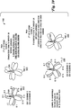
- FIGS 5A -5E illustrate a first example sequence of beamformed signals transmitted by a TRP.
- Figure 5A illustrates a diagram 500 of simultaneously transmitted beamformed synchronization signals made by TRP 505 at a first time interval. As shown in Figure 5A, at the first time interval, TRP 505 simultaneously transmits 4 beamformed synchronization signals on 4 transmission beams that are spatially separated by 90 degrees.
- a first transmission beam 507 transmits a beamformed synchronization signal with identifier ID 1
- a second transmission beam 509 transmits a beamformed synchronization signal with identifier ID 5
- a third transmission beam 511 transmits a beamformed synchronization signal with identifier ID 9
- a fourth transmission beam 513 transmits a beamformed synchronization signal with identifier ID 13.
- the arrangement of transmission beams that are used to simultaneously transmit beamformed synchronization signals is referred to as a set of spatially separated transmission beams.
- Figure 5B illustrates a diagram 520 of simultaneously transmitted beamformed synchronization signals made by TRP 505 at a second time interval.
- TRP 505 simultaneously transmits 4 beamformed synchronization signals on 4 transmission beams that are spatially separated by 90 degrees, however the 4 transmission beams are rotated by one beam width. In addition to the rotation, the identifiers of the beamformed synchronization signals are also changed.
- FIG. 5C illustrates a diagram 530 of simultaneously transmitted beamformed synchronization signals made by TRP 505 at a third time interval.
- TRP 505 simultaneously transmits 4 beamformed synchronization signals on 4 transmission beams that are spatially separated by 90 degrees with the 4 transmission beams being rotated by another beam.
- the identifiers of the beamformed synchronization signals are also changed.
- Figure 5D illustrates a diagram 540 of simultaneously transmitted beamformed synchronization signals made by TRP 505 at a fourth time interval.
- TRP 505 simultaneously transmits 4 beamformed synchronization signals on 4 transmission beams that are spatially separated by 90 degrees with the 4 transmission beams being rotated by yet another beam.
- the identifiers of the beamformed synchronization signals are also changed. It is noted that the same set of spatially separated transmission beams is used in all four time intervals, only differing in identifiers and by rotation.
- the transmission of the beamformed synchronization signals in four rotations as shown in Figures 5A -5D encompasses the full coverage area of TRP 505 and uses all available transmission beams.
- TRP 505 has transmitted beamformed synchronization signals using all available transmission beams. If different numbers of transmission beams are available or if a different configuration of transmission beams are used per rotation, then different number of rotations may be needed to fully encompass the full coverage area of TRP 505. Furthermore, each rotation shown in Figures 5A -5D involves a rotation amount equal to 1 beam width. Other values for rotation amounts are possible, such as 2 beams, 3 beams, and so forth.
- FIG. 5E illustrates a diagram 550 of simultaneously transmitted beamformed broadcast signals made by TRP 505.
- TRP 505 simultaneously transmits beamformed broadcast signals on all available transmission beams with TX diversity to fully encompass the coverage area of TRP 505.
- Any of the previously described techniques for transmitting beamformed broadcast signals such as using different subbands, or a combination of different subbands and TX diversity, etc., may be used.
- the four transmissions shown in Figures 5A -5D make up a synchronization cycle, and the four transmissions shown in Figures 5A -5D with the transmission shown in Figure 5E is referred to as a synchronizing cycle and/or frame structure.
- the beamformed broadcast signals are shown in Figure 5E as being transmitted by TRP 505, in alternative deployments, a different device may be responsible for providing the broadcast information.
- a small cell TRP transmits the beamformed synchronization signals, while a legacy eNB transmits the broadcast signal.
- the number of broadcast signals would generally be fixed by the operator of the communications system or technical standard. Depending upon the detected beam identifier, a UE would know the time offset in order to receive the beamformed broadcast signal from the TRP.
- the configuration shown in Figures 5A -5E may be expressed in simplified notation as
- the TRP may transmit the beamformed broadcast signals on a subset of all transmission beams and rotate the beams in a manner similar to the rotation of the beams discussed in the transmission of the beamformed synchronization signals.
- FIGS 6A -6F illustrate a second example sequence of beamformed signals transmitted by a TRP.
- Figure 6A illustrates a diagram 600 of simultaneously transmitted beamformed synchronization signals made by TRP 605 at a first time interval.
- TRP 605 simultaneously transmits 4 beamformed synchronization signals on a set of spatially separated transmission beams comprising 4 transmission beams that are spatially separated by 90 degrees in a manner similar to what is shown in Figure 5A.
- Figure 6B illustrates a diagram 610 of simultaneously transmitted beamformed synchronization signals made by TRP 605 at a second time.
- TRP 605 simultaneously transmits 4 beamformed synchronization signals on 4 transmission beams that are spatially separated by 90 degrees, however the 4 transmission beams are rotated by one beam width. In addition to the rotation, the identifiers of the beamformed synchronization signals are also changed.
- Figure 6C illustrates a diagram 620 of simultaneously transmitted beamformed broadcast signals made by TRP 605 in a third time interval. Due to limitations of TRP 605, TRP 605 can only simultaneously beamform and transmit beamformed broadcast signals on 8 transmission beams, for example.
- a set of transmission beams includes 4 groups of 2 adjacent transmission beams with a 90 degree spatial separation between each group.
- the set of transmission beams used by TRP 605 to transmit the beamformed broadcast signals include the same transmission beams used by TRP 605 to transmit the beamformed synchronization signals in time intervals 1 ( Figure 6A) and 2 ( Figure 6B) .
- a group of transmission beams comprises transmission beams 625 and 627.
- TRP 605 may use TX diversity and/or different subbands in the transmission of the beamformed broadcast signals.
- the three transmissions shown in Figures 6A -6C make up a first synchronizing cycle or frame structure, while the two transmissions shown in Figures 6A and 6B make up a first synchronization cycle.
- Figure 6D illustrates a diagram 640 of simultaneously transmitted beamformed synchronization signals made by TRP 605 at a fourth time interval.
- TRP 605 simultaneously transmits 4 beamformed synchronization signals on 4 transmission beams that are spatially separated by 90 degrees, however the 4 transmission beams are rotated by an additional beam width.
- the identifiers of the beamformed synchronization signals are also changed.
- Figure 6E illustrates a diagram 650 of simultaneously transmitted beamformed synchronization signals made by TRP 605 at a fifth time interval.
- TRP 605 simultaneously transmits 4 beamformed synchronization signals on 4 transmission beams that are spatially separated by 90 degrees, however the 4 transmission beams are rotated by another beam width. In addition to the rotation, the identifiers of the beamformed synchronization signals are also changed.
- Figure 6F illustrates a diagram 660 of simultaneously transmitted beamformed broadcast signals made by TRP 605 in a sixth time interval.
- the set of transmission beams used to transmit the beamformed broadcast signals as shown in Figure 6F is similar to the set of transmission beams shown in Figure 6C with exception of a rotation being applied to the set of transmission beams.
- the set of transmission beams used by TRP 605 to transmit the beamformed broadcast signals include the same transmission beams used by TRP 605 to transmit the beamformed synchronization signals in time intervals 4 ( Figure 6D) and 5 ( Figure 6E).
- transmission beams 665 and 667 correspond to transmission beams 625 and 627 shown in Figure 6C.
- the rotation is equal to 2 beam widths.
- the amount of rotation differs based on the total number of transmission beams, the number of transmission beams per group, and the number of sets of transmission beams.
- the three transmissions shown in Figures 6D -6F make up a second synchronizing cycle or frame structure, while the two transmissions shown in Figures 6D and 6E make up a second synchronization cycle.
- the six transmissions shown in Figures 6A -6F make up a complete synchronizing cycle or frame structure.
- the beamformed broadcast signals are shown in Figures 6C and 6F as being transmitted by TRP 605, in alternative deployments, a different device may be responsible for providing the broadcast information.
- a small cell TRP transmits the beamformed synchronization signals, while a legacy eNB transmits the broadcast signals.
- the number of beamformed synchronization signals and the number of beamformed synchronization signals to beamformed broadcast signals would generally be fixed by the operator of the communications system or technical standard. Then, depending upon the detected beam identifier, a UE would know the time offset to receive the beamformed broadcast signals.
- the configuration shown in Figures 6A -6F may be expressed in simplified notation as
- the example embodiments presented herein enable a reduction in communications overhead by reducing the number of time intervals the beamformed broadcast signals are transmitted. If the beamformed broadcast signals are transmitted every time after the transmission of the beamformed synchronization signals, the resulting overhead would be greater.
- synchronization signals i.e., PSS and SSS
- RBs resource blocks
- SCs guard subcarriers
- the minimum bandwidth allocation may be different, so the number of subcarriers for the synchronization signals may also change.
- beamformed synchronization signals that are transmitted using wideband RF beamforming are transmitted in separate blocks in the frequency domain.
- the beamformed synchronization signals are transmitted in separate blocks in the frequency domain, even the UEs that only have the minimum bandwidth allocation can acquire the beamformed synchronization signals at the same rate as the UEs that have greater bandwidth allocation.
- the UEs with greater bandwidth allocations still have the advantage of lower signal to noise ratio (SNR) due to frequency diversity arising from their greater bandwidth allocation.
- SNR signal to noise ratio
- Figure 7 illustrates an example time-frequency plot 700 highlighting the transmission of beamformed synchronization signals in separate frequency blocks.
- beamformed synchronization signals are transmitted in separate frequency blocks, such as frequency blocks 705, 707, 709, and 711.
- the same transmission beams may be used to transmit the beamformed synchronization signals in the different frequency blocks at the same time interval.
- the TRP When digital (or hybrid) beamforming is used at a TRP for transmitting beamformed synchronization signals in separate frequency blocks, it may be possible for the TRP to transmit differently rotated beamformed synchronization signals in the frequency domain.
- the number of frequency blocks in the frequency domain used to transmit the beamformed synchronization signals may need to be limited so that even the most basic UE receiver with the lowest allocated bandwidth is able to derive benefits of the beamformed synchronization signals.
- rotations in the time domain and frequency multiplexing are used to reduce synchronization overhead. It is noted that UEs with limited bandwidth allocations can still utilize such a system when the rotations in the frequency domain cover a limited number of subbands.
- the application of rotations in the time domain and frequency multiplexing enables TRPs with neighboring transmission beams with potential cross-interference issues to transmit the beamformed synchronization signals at the same time but in different subbands to avoid interference. Additionally, because the different subbands are orthogonal, the number of orthogonal sequences needed is reduced by a factor of N, where N is the number of subbands.
- Figure 8 illustrates an example time-frequency plot 800 highlighting the transmission of beamformed synchronization signals in separate frequency blocks with rotations.
- frequency blocks such as frequency blocks 805 and 807, occurring at the first time are used to transmit beamformed synchronization signals with different sets of transmission beams.
- set of transmission beams 806 is used in frequency block 805 and set of transmission beams 808 is used in frequency block 807.
- frequency blocks 810 and 812 are used to transmit synchronization signals with sets of transmission beams 811 and 813, respectively. It is noted that the sets of transmission beams may have the same base set of transmission beams, but with different rotations.
- FIG. 9 illustrates a third example sequence of beamformed transmissions 900 made by a TRP 905.
- TRP 905 is transmitting beamformed signals in different frequency blocks with rotations applied at different times.
- time_1 910 TRP 905 transmits beamformed synchronization signals using a total of 8 transmission beams, with a first set of 4 spatially separated transmission beams (unshaded beams) transmitted in a first subband and a second set of 4 spatially separated transmission beams (crosshatched beams) transmitted in a second subband.
- Each transmission beam has a different beam identity.
- TRP 905 transmits beamformed synchronization signals using a total of 8 transmission beams, with a first set of 4 spatially separated transmission beams transmitted in a first subband and a second set of 4 spatially separated transmission beams transmitted in a second subband.
- the sets of 4 spatially separated transmission beams used in second time 915 are rotated versions of the sets of 4 spatially separated transmission beams used in first time 910. Each transmission beam has a different beam identity.
- TRP 905 transmits beamformed broadcast signals using a total of 16 transmission beams, which includes all of the transmission beams used to transmit the beamformed synchronization signals in first time 910 and second time 915. Any of the previously described techniques for transmitting beamformed broadcast signals, such as using TX diversity, different subbands, or a combination of different subbands and TX diversity, etc., may be used.
- FIG 10 illustrates a fourth example sequence of beamformed transmissions made by a TRP 1005.
- TRP 1005 is transmitting beamformed signals in different frequency blocks with rotations.
- TRP 1005 transmits beamformed synchronization signals using a total of 8 transmission beams, with a first set of 4 spatially separated transmission beams (unshaded beams) transmitted in a first subband and a second set of 4 spatially separated transmission beams (crosshatched beams) transmitted in a second subband.
- Each transmission beam has a different beam identity.
- time_2 1015 TRP 1005 transmits beamformed broadcast signals using 8 transmission beams, the same 8 transmission beams used in first time 1010.
- any of the previously described techniques for transmitting beamformed broadcast signals may be used.
- TRP 1005 beamformed synchronization signals using a total of 8 transmission beams with a first set of 4 spatially separated transmission beams transmitted in a first subband and a second set of 4 spatially separated transmission beams transmitted in a second subband.
- the sets of 4 spatially separated transmission beams used in third time 1020 are rotated versions of the sets of 4 spatially separated transmission beams used in first time 1010.
- TRP 1005 transmits beamformed broadcast signals using 8 transmission beams, the same 8 transmission beams used in third time 1020. Any of the previously described techniques for transmitting beamformed broadcast signals, such as using TX diversity, different subbands, or a combination of different subbands and TX diversity, etc., may be used.
- the number of sequences required is reduced from 16 down to 8 in order to ensure that the UE is able to identify the beam identifiers of the transmission beams. Furthermore, the number of time intervals for transmitting the beamformed synchronization signals can be reduced from 4 down to 2.
- beamformed synchronization signals are simultaneously transmitted on a plurality of spatially separated transmission beams, with unique angular spacing between neighboring active transmission beams.
- the transmission beams transmitted together have the same identifier.
- the transmission beams are rotated in time with each rotation having a different identifier.
- the unique angular spacing between active transmission beams eliminates ambiguity. Communications systems that use wider beams and/or communications systems that operate in an environment when there are higher incidents of multiple reflections are good candidates for this example embodiment.
- the beamformed synchronization signals are simultaneously transmitted on a set of spatially separated transmission beams, where all of the transmission beams have the same beam identity.
- the transmission beams in the set of spatially separated transmission beams are referred to as active beams. TX diversity may be used.
- the angular spacing between the active beams is different in the angular coverage area.
- the angular coverage area may be a sector (such as 120 degrees) or 360 degrees.
- the active beams rotate with time, and in each rotation the active beams have a different beam identifier.
- the angular spacings between the active beams are maintained between rotations, and are used to help eliminate ambiguity.
- Figure 11 illustrates an example sequence of beamformed synchronization signals transmitted by a TRP 1105, where the active beams are spatially separated and have the same beam identity. As shown in Figure 11, a total of 9 rotations of the active beams is needed to provide full coverage, compared to 16 rotations if a single transmission beam was rotated.
- TRP 1105 transmits the active beams as configured by first synchronization signals configuration (SCH_1) 1110.
- First synchronization signals configuration 1110 includes 3 transmission beams (labeled beams A, B, and C) .
- the spatial separation between beams A and B is X (e.g., 3 beams)
- the spatial spacing between beams B and C is Y (e.g., 5 beams)
- the spatial separation between beams C and A is Z (e.g., 7 beams) .
- TRP 1105 transmits the active beams as configured by second synchronization signals configuration (SCH_2) 1115.
- Second synchronization signals configuration 1115 is a rotation of first synchronization signals configuration 1110 by an angular amount, e.g., a beam width.
- TRP 1105 transmits the active beams as configured by third synchronization signals configuration (SCH_3) 1120.
- TRP 1105 transmits the active beams as configured by fourth synchronization signals configuration (SCH_4) 1125.
- TRP 1105 transmits the active beams as configured by fifth synchronization signals configuration (SCH_5) 1130.
- TRP 1105 transmits the active beams as configured by sixth synchronization signals configuration (SCH_6) 1135.
- SCH_7 transmits the active beams as configured by seventh synchronization signals configuration (SCH_7) 1140.
- SCH_8 transmits the active beams as configured by eighth synchronization signals configuration (SCH_8) 1145.
- TRP 1105 transmits the active beams as configured by ninth synchronization signals configuration (SCH_9) 1150.
- the active beams, the synchronization signal configurations, and the rotations illustrated in Figure 11 are examples provided for discussion and are not intended to limit the scope or the spirit of the example embodiments. Alternate configurations of active beams, synchronization signal configurations, and rotations are possible as long as the total angular space (360 degrees in this example) is swept and that angular locations that are beamformed at the same time (i.e., transmission beams A, B, and C) have a unique spatial separation and transmit the same beam identifiers (beam identifying sequences, for example) to eliminate ambiguity. Each rotation of the beams in the time sequence transmits a different beam identifiers.
- Table 2 displays a set of beam identifiers that are detectable by UEs that are located in the coverage area of TRP 1105.
- the UE location in degrees is the angle relative to TRP, as shown in Figure 12, which illustrates the relative angle between UE 1205 and TRP 1105. It is noted that at each position in the coverage area of TRP 1105, a UE detects a unique set of beam identities. Therefore, the UE is able to determine an orientation with respect to TRP 1105 and a beam index.
- Table 2 Beam identifiers that are detectable by UEs that are located in the coverage area of a TRP.
- FIG. 13 illustrates a fourth example sequence of beamformed transmissions made by a TRP 1305.
- TRP 1305 is transmitting beamformed signals using a set of spatially separated transmission beams (i.e., active beams) with rotations applied at different time intervals. All active beams have the same beam identity in a single time interval.
- TRP 1305 transmits beamformed synchronization signals using 3 active beams with beam identity 1.
- time_2 transmits beamformed synchronization signals using 3 active beams with beam identity 2.
- time_3 time
- TRP 1305 transmits beamformed synchronization signals using 3 active beams with beam identity 3.
- TRP 1305 transmits beamformed synchronization signals using 3 active beams with beam identity 4.
- TRP 1305 transmits beamformed synchronization signals using 3 active beams with beam identity 5.
- TRP 1305 transmits beamformed synchronization signals using 3 active beams with beam identity 6.
- time_7 transmits beamformed synchronization signals using 3 active beams with beam identity 7.
- time_8 transmits beamformed synchronization signals using 3 active beams with beam identity 8.
- TRP 1305 transmits beamformed synchronization signals using 3 active beams with beam identity 9.
- TRP 1305 transmits beamformed broadcast signals using all available transmission beams. Any of the previously described techniques for transmitting beamformed broadcast signals, such as using TX diversity, different subbands, or a combination of different subbands and TX diversity, etc., may be used. If a TRP is not capable of simultaneously transmitting the beamformed broadcast signals on all transmission beams, the beamformed broadcast signals may be transmitted in different subsets of all transmission beams in different subframes.
- the UE When a UE detects a beamformed synchronization signal (and synchronizes its receiver) , the UE will know the timing offset to receive and demodulate the beamformed broadcast signals because the frame structure is fixed. Due to the nature of this example embodiment, all time instances of the beamformed synchronization signals (e.g., subframes) will be received before the UE can unambiguously determine which beam direction from the TRP is the best direction. Once the UE has detected at least one beam identity with the correct timing, the UE may need to continue detecting to the subsequent sets of beamformed synchronization signals in order to fully establish the correct beam from the TRP.
- the beamformed synchronization signals e.g., subframes
- the beamformed synchronization signals are transmitted in multiple subbands with the same transmission beam directions to support frequency diversity or with different transmission beam directions to reduce overhead in the time dimension.
- different beam identifiers are used.
- FIG 14 illustrates a fifth example sequence of beamformed transmissions made by a TRP 1405.
- TRP 1405 is transmitting beamformed signals using a set of spatially separated transmission beams (i.e., active beams) in different frequency subbands with rotations applied at different times with the number of subbands equal to 3. All active beams within a single frequency subband in a single time have the same beam identity, but the beam identities change in different time intervals, even for the same active beams within the single frequency subband.
- a set of spatially separated transmission beams i.e., active beams
- TRP 1405 transmits beamformed synchronization signals using active beams with beam identifier 1 (shown as white beams in combined first transmissions 1411) , at the same time and in a second subband TRP 1405 transmits beamformed synchronization signals using the active beams using a first rotation with beam identifier 2 (shown as hatched beams in combined first transmissions 1411) , and at a third subband TRP 1405 transmits beamformed synchronization signals using active beams after a second rotation with beam identifier 3 (shown as cross hatched beams in combined first transmissions 1411) .
- TRP 1405 transmits beamformed synchronization signals using active beams with beam identifier 4 (shown as white beams in combined second transmissions 1412) , and at the same time TRP 1405 transmits beamformed synchronization signals using the active beams after the first rotation with beam identifier 5 (shown as hatched beams in combined second transmissions 1412) , and at the same time TRP 1405 transmits beamformed synchronization signals using active beams using a further rotation with beam identifier 6 (shown as cross hatched beams in combined second transmissions 1412) .
- TRP 1405 transmits beamformed synchronization signals using active beams with beam identifier 7 (shown as white beams in combined third transmissions 1415)
- TRP 1405 transmits beamformed synchronization signals using the active beams rotated and with beam identifier 8 (shown as hatched beams in combined third subband transmissions 1415)
- TRP 1405 transmits beamformed synchronization signals using active beams rotated with beam identifier 9 (shown as cross hatched beams in combined third transmissions 1415)
- TRP 1405 transmits beamformed broadcast signals as shown in combined transmissions 1416. Any of the previously described techniques for transmitting beamformed broadcast signals, such as using TX diversity, different subbands, or a combination of different subbands and TX diversity, etc., may be used.
- the UE In order for a UE to demodulate system information from beamformed broadcast signals, the UE needs to be time (on a frame and subframe basis) and frequency synchronized with the TRP. As discussed previously, if the UE is able to determine the TRP beam index, the UE will also know the time offset between the received beamformed synchronization signal and the beamformed broadcast signals. Other benefits may be involved with the obtaining of the TRP beam index, as described below.
- FIG. 15 illustrates a diagram 1500 of messages exchanged and processing performed by devices participating in synchronization.
- Devices participating in synchronization include a TRP 1505, a UE 1510, and a legacy eNB 1515.
- a legacy connection 1520 exists between UE 1510 and legacy eNB 1515.
- TRP 1505 transmits beamformed synchronization signals and beamformed broadcast signals (events 1522 and 1523) , and UE 1510 receives the beamformed synchronization signals (event 1524) and determines time and frequency synchronization, as well as best beam identity (block 1526) .
- UE 1510 provides feedback of the best beam identity, as well as optionally identifier of TRP 1505 to legacy eNB 1515 (event 1528) .
- Legacy eNB 1515 prepares TRP 1505 for beamformed RACH (event 1530) , by providing the information received from UE 1510, for example.
- UE 1510 transmits a beamformed RACH that is already pre-aligned to TRP 1505 (event 1532) .
- identifying and providing feedback about beam identities of neighboring TRPs can also accelerate neighbor cell reporting compared to simply providing feedback about the beam-formed CSI-RS of the neighboring TRPs.
- This acceleration compared to using beam-formed CSI-RS is due to the fact, that beamformed CSI-RS indices of neighboring cells can only be obtained once the CSI-RS configuration of the neighboring TRPs is known by the UE (by demodulating the beamformed broadcast signals or otherwise, for example) before the beamformed CSI-RS can be demodulated.
- different sets of sequences may be used to identify each of the beamformed synchronization signals.
- SC/FDE single carrier modulation with frequency domain equalization
- Golay codes may be chosen, while if the communications system is using orthogonal frequency division multiplexing (OFDM) , Zadoff-Chu (ZC) sequences may be chosen.
- Golay codes and ZC sequences are intended to be examples.
- FIG 16 illustrate a diagram 1600 of PSS and SSS in current generation 3GPP LTE communications systems.
- the same PSS is sent twice in every frame (every 10 slots) and indicates the physical (PHY) layer identity N ID (2) (0, 1, 2) based on the root of the ZC sequence root.
- the SSS sequence is an interleaved combination of two length-31 sequences and is scrambled by a sequence derived from the PSS (the combination changes between slot 0 and slot 10.
- the UE can obtain frame and slot timing, as well as obtain the cell identifier from the synchronization phase.
- the total required overhead is 6 RBs in 4 slots of each frame (each frame has 120 slots) .
- the exact overhead depends upon the system bandwidth use, but may be as high as 3.33 %when the system bandwidth is only 6 RBs.
- Beam identifier spatial synchronization
- frequency and time frame and slot
- Cell identifier Cell identifier
- beam identifier spatial synchronization
- frequency and time frame and slot
- Figure 17 illustrates a first example beamformed synchronization signal payload and frame structure 1700 for spatial, frequency and time synchronization.
- Beamformed synchronization signal frame structure 1700 includes 10 subframes with 2 slots each subframe, including slot 0 1705 of subframe 0 1707 and slot 10 1710 of subframe 5 1712.
- Slot 0 1705, as well as slot 10 1710 comprises a plurality of symbols, some of which are used to convey the beamformed synchronization signals.
- symbol 1715 of slot 0 1705 includes RBs, such as RBs 1720, dedicated for transmitting the beamformed synchronization signals, as well as other RBs, such as RBs 1722 and 1724, which are used by other signals.
- the sequences used in the second half of a frame structure are complementary versions of the sequences used in the first half of frame structure, so the different parts of the frame can be identified and the sub-frame and frame timing can be established.
- each beamformed synchronization signal symbol is transmitted twice in each frame.
- Search complexity may be simplified and frame and slot timing is enabled.
- complementary sequences may include cyclically shifted sequences, conjugated sequences, sequences with different roots, phase shifts and so on.
- Figure 18 illustrates a second example beamformed synchronization signal payload and frame structure 1800 for spatial, frequency and time synchronization.
- Beamformed synchronization signal frame structure 1800 includes 10 subframes with 2 slots in each subframe, including slot 0 1805 of subframe 0 1807 and slot 10 1810 of subframe 5 1812.
- Slot 0 1805, as well as slot 10 1810 comprises a plurality of symbols, some of which are used to convey the beamformed synchronization signals.
- symbol 1815 of slot 0 1805 includes RBs, such as RBs 1820 and 1821, dedicated for transmitting different rotations of the beamformed synchronization signals, as well as other RBs, such as RBs 1822 and 1824, dedicated for other uses.
- RBs 1820 is used to transmit a first rotation of the beamformed synchronization signals
- RBs 1821 is used to transmit a second rotation of the beamformed synchronization signals.
- the sequences used in the second half of a frame structure are complementary versions of the sequences used in the first half of frame structure so the different parts of the frame can be identified and the sub-frame and frame timing can be established.
- the number of beamformed synchronization signal symbols may be reduced by a factor of M/N as shown in Figure 18, where M is the normal number of rotations needed and N is the number of frequency subbands.
- each active beam transmitting a beamformed synchronization signal includes a beam identifier, a SSS, and a PSS.
- Figure 19A illustrates a first example beamformed synchronization signal format 1900.
- Beamformed synchronization signal format 1900 includes a beam identifier field 1905, a SSS field 1910, and a PSS field 1915.
- Beam identifier field 1905 includes a sequence that is related to the beam identifier associated with the active beam.
- SSS field 1910 includes a sequence that is related to the SSS, such as a scrambling code.
- PSS field 1915 includes a sequence that is the same for all active beams from a single TRP.
- the sequence is mapped to PHY layer identity N ID (2) .
- each active beam transmitting a beamformed synchronization signal includes a beam identifier and a SSS combined into one sequence, and a PSS.
- Figure 19B illustrates a second example beamformed synchronization signal format 1950.
- Beamformed synchronization signal format 1950 includes a SSS field 1955 and a PSS field 1960.
- SSS field 1955 includes a sequence to the SSS, such as a scrambling code.
- the sequence is mapped to N ID (1) and the sequence used in slot 0 is different from the sequence used in slot 10.
- the sequence is also mapped to the beam identifier, such as a phase shift, a cyclic shift, a code group mapping, and so on.
- the UE In order for a UE to detect beamformed synchronization signals, the UE will generally listen on all available receiver chains and will have a bank of parallel correlators matched to known sequences. In a situation when the UE uses beamforming, e.g., with 90 degree half power bandwidth (HPBW) beams, the different receiver chains may listen to different beam directions simultaneously. If the UE has 4 receive chains, the UE would be able to listen in all directions (360 degrees) simultaneously. The number of available receiver chains at the UE may be lower if the UE is monitoring neighboring TRPs at the same time as it is receiving from the connected TRP.
- beamforming e.g., with 90 degree half power bandwidth (HPBW) beams
- the different receiver chains may listen to different beam directions simultaneously. If the UE has 4 receive chains, the UE would be able to listen in all directions (360 degrees) simultaneously.
- the number of available receiver chains at the UE may be lower if the UE is monitoring neighboring TRPs at the same time
- the beamformed synchronization signals may be coordinated in time, frequency, and angular space, so that cell edge users only receive one beamformed synchronization signal at a given frequency-time resource.
- Techniques for coordinating devices in the time, frequency, and angular space are discussed in co-assigned patent application entitled “System and Method for beam-formed reference and control signals, " US application number 14/815,571, filed July 31, 2015, which is hereby incorporated herein by reference.
- the TRPs may only be required for the TRPs to be coordinated when the TRPs are part of an ultra-dense network (UDN) or when each user's beam can receive signals from different TRP simultaneously.
- UDN ultra-dense network
- Figure 20A illustrates a flow diagram of first example operations 2000 occurring in a TRP transmitting beamformed control signals.
- Operations 2000 may be indicative of operations occurring in a TRP of a communications system as the TRP transmits beamformed control signals, including synchronization signals and broadcast signals.
- Operations 2000 begin with the TRP determining a set of spatially separated transmission beams (block 2005) .
- the set of spatially separated transmission beams may be specified by a technical standard or an operator of the communications system. In such a situation, the set of spatially separated transmission beams may be stored in memory of the TRP. Alternatively, the TRP may retrieve the set of spatially separated transmission beams from a server (local or remote) or from some other device in the communications system The set of spatially separated transmission beams may be coordinated with sets of spatially separated transmission beams of neighboring TRPs. Alternatively, the TRP may select the set of spatially separated transmission beams.
- the selection of the set of spatially separated transmission beams may be made in accordance with factors such as a number of available transmission beams, a number of available frequency subbands, beamforming capabilities of the TRP, receive capabilities of the UEs, mobility of the UEs, tolerable communications overhead, tolerable synchronization latency, and so on.
- the TRP beamforms a synchronization signal in accordance with the set of spatially separated transmission beams (block 2010) . If multiple subbands are used, the TRP may beamform the synchronization signal in accordance with the set of spatially separated transmission beams for each of the subbands.
- the TRP transmits the beamformed synchronization signals (block 2015) .
- the transmission of the beamformed synchronization signals may occur in a single band or in multiple subbands, depending on the configuration of the communications system.
- the TRP performs a check to determine if a synchronization cycle is complete (block 2020) . As an example, the synchronization cycle is complete if the TRP has transmitted beamformed synchronization signals on all available transmission beams.
- the synchronization cycle may be shorter than what is needed to allow the TRP to transmit beamformed synchronization signals on all available transmission beams.
- An example of such synchronization cycles are shown in Figures 6A -6F, where a full synchronization cycle would comprise 4 rotations of the set of spatially separated transmission beams but the synchronization cycle is partitioned into two separate synchronization cycles of 2 rotations of the set of spatially separated transmission beams each. If the synchronization cycle is not complete, the TRP rotates the set of spatially separated transmission beams (block 2025) .
- the rotation of the set of spatially separated transmission beams is specified during the determining of the set of spatially separated transmission beams and ensures that the TRP transmits the beamformed synchronization signals on all available transmission beams by the time the synchronization cycle (or synchronization cycles in the situation where the synchronization cycle is shorter than what is needed to allow the TRP to transmit beamformed synchronization signals on all available transmission beams) is complete.
- the TRP returns to block 2010 to beamform the synchronization signal in accordance with the rotated set of spatially separated transmission beams.
- the TRP beamforms a broadcast signal (block 2030) and transmits the beamformed broadcast signals (block 2035) . Any of the previously described techniques for transmitting beamformed broadcast signals, such as using TX diversity, different subbands, or a combination of different subbands and TX diversity, etc., may be used. If the synchronization cycle was partitioned into multiple synchronization cycles, the TRP returns to block 2010 to start another synchronization cycle. The TRP performs a check to determine if the synchronizing cycle is complete (block 2040) .
- the TRP changes the set of spatially separated transmission beams (which may be as simple as applying a rotation to the set of spatially separated transmission beams) and returns to block 2010 to continue transmission of beamformed synchronization signals.
- a first synchronization cycle comprises transmissions on 2 rotations of the set of spatially separated transmission beams as shown in Figures 6A and 6B and a second synchronization cycle comprises transmissions on 2 rotations of the set of spatially separated transmission beams as shown in Figures 6D and 6E, while the synchronizing cycle comprises the transmissions as shown in Figures 6A-6F.
- the TRP may prepare for RACH reception from a UE (block 2040) .
- FIG. 20B illustrates a flow diagram of second example operations 2050 occurring in a TRP transmitting beamformed signals.
- Operations 2050 may be indicative of operations occurring in a TRP of a communications system as the TRP transmits beamformed signals, including synchronization signals. It is noted that operations 2050 may be applicable in situations where an entity other than the TRP transmits broadcast signals, such as in a heterogeneous deployment or a dual connectivity deployment, transmits broadcast signals and the TRP transmits beamformed signals (including synchronization signals) .
- Operations 2050 begin with the TRP determining a set of spatially separated transmission beams (block 2055) .
- the set of spatially separated transmission beams may be specified by a technical standard or an operator of the communications system. In such a situation, the set of spatially separated transmission beams may be stored in memory of the TRP. Alternatively, the TRP may retrieve the set of spatially separated transmission beams from a server (local or remote) or from some other device in the communications system The set of spatially separated transmission beams may be coordinated with sets of spatially separated transmission beams of neighboring TRPs. Alternatively, the TRP may select the set of spatially separated transmission beams.
- the selection of the set of spatially separated transmission beams may be made in accordance with factors such as a number of available transmission beams, a number of available frequency subbands, beamforming capabilities of the TRP, receive capabilities of the UEs, mobility of the UEs, tolerable communications overhead, tolerable synchronization latency, and so on.
- the TRP beamforms a synchronization signal in accordance with the set of spatially separated transmission beams (block 2060) . If multiple subbands are used, the TRP may beamform the synchronization signal in accordance with the set of spatially separated transmission beams for each of the subbands.
- the TRP transmits the beamformed synchronization signals (block 2065) .
- the transmission of the beamformed synchronization signals may occur in a single band or in multiple subbands, depending on the configuration of the communications system.
- the TRP performs a check to determine if a synchronization cycle is complete (block 2070) . As an example, the synchronization cycle is complete if the TRP has transmitted beamformed synchronization signals on all available transmission beams.
- the synchronization cycle may be less than what is needed to allow the TRP to transmit beamformed synchronization signals on all available transmission beams.
- An example of such synchronization cycles are shown in Figures 6A -6F, where a full synchronization cycle would comprise 4 rotations of the set of spatially separated transmission beams but the synchronization cycle is partitioned into two separate synchronization cycles of 2 rotations of the set of spatially separated transmission beams each. If the synchronization cycle is not complete, the TRP rotates the set of spatially separated transmission beams (block 2075) .
- the rotation of the set of spatially separated transmission beams is specified during the determining of the set of spatially separated transmission beams and ensures that the TRP transmits the beamformed synchronization signals on all available transmission beams by the time the synchronization cycle is complete.
- the TRP returns to block 2060 to beamform the synchronization signal in accordance with the rotated set of spatially separated transmission beams. If the synchronization cycle is complete, the TRP performs a check to determine if the synchronizing cycle is complete (block 2080) .
- the TRP changes the set of spatially separated transmission beams (which may be as simple as applying a rotation to the set of spatially separated transmission beams) (block 2085) and returns to block 2060 to continue transmission of beamformed synchronization signals.
- the TRP may prepare for RACH reception from a UE (block 2090) .
- Figure 21 illustrates a flow diagram of example operations 2100 occurring in a UE performing synchronization.
- Operations 2100 may be indicative of operations occurring in a UE of a communications system as the UE performs synchronization utilizing beamformed control signals, including synchronization signals and broadcast signals.
- Operations 2100 begins with the UE performing a check to determine if a beamformed synchronization signal has been received (block 2105) . If a beamformed synchronization signal has been received, the UE determines the beam identifier of the received beamformed synchronization signal (block 2110) . The UE performs a check to determine if the synchronization cycle is complete (block 2115) . If the synchronization cycle is not complete, the UE returns to block 2105 to potentially receive additional beamformed synchronization signals. The UE may not receive any other beamformed synchronization signals depending on the location of the UE with respect to the TRP transmitting the beamformed synchronization signals.
- the UE determines a beam index of a transmission beam oriented towards the UE (block 2120) .
- the determination of the beam index is made using the one or more beam identities of the one or more beamformed synchronization signals received by the UE, as determined in block 2110.
- the UE receives a broadcast signal (block 2125) .
- the broadcast signal may be a beamformed broadcast signal from the TRP, such as described in Figure 20A.
- the broadcast signal may be received from a legacy eNB in a dual connectivity deployment.
- the discussion focuses on the broadcast signal being received once the synchronization cycle is complete, the broadcast signal may be received at any time, such as before the synchronization cycle, during the synchronization cycle, or after the synchronization cycle.
- the UE is not ensured of receiving either a beamformed synchronization signal or a beamformed broadcast signal in any given synchronization cycle. However, the UE is ensured of receiving at least one beamformed synchronization signal and one broadcast signal over the entirety of the synchronizing cycle.
- the UE optionally feeds back the beam index (block 2130) .
- the beam index may be fedback to a legacy eNB that is serving the UE.
- the UE performs a RACH procedure with the TRP (block 2135) .
- the TRP can use this beam index information to prepare the TRP to receive on the correct beam for the RACH procedure.
- UE uses the beam index for timing information and to know when to transmit the RACH.
- the UE may beamform the RACH transmission in accordance with the beam index.
- Figure 22 illustrates a block diagram of an embodiment processing system 2200 for performing methods described herein, which may be installed in a host device.
- the processing system 2200 includes a processor 2204, a memory 2206, and interfaces 2210-2214, which may (or may not) be arranged as shown in Figure 22.
- the processor 2204 may be any component or collection of components adapted to perform computations and/or other processing related tasks
- the memory 2206 may be any component or collection of components adapted to store programming and/or instructions for execution by the processor 2204.
- the memory 2206 includes a non-transitory computer readable medium.
- the interfaces 2210, 2212, 2214 may be any component or collection of components that allow the processing system 2200 to communicate with other devices/components and/or a user.
- one or more of the interfaces 2210, 2212, 2214 may be adapted to communicate data, control, or management messages from the processor 2204 to applications installed on the host device and/or a remote device.
- one or more of the interfaces 2210, 2212, 2214 may be adapted to allow a user or user device (e.g., personal computer (PC) , etc. ) to interact/communicate with the processing system 2200.
- the processing system 2200 may include additional components not depicted in Figure 22, such as long term storage (e.g., non-volatile memory, etc. ) .
- the processing system 2200 is included in a network device that is accessing, or part otherwise of, a telecommunications network.
- the processing system 2200 is in a network-side device in a wireless or wireline telecommunications network, such as a base station, a relay station, a scheduler, a controller, a gateway, a router, an applications server, or any other device in the telecommunications network.
- the processing system 2200 is in a user-side device accessing a wireless or wireline telecommunications network, such as a mobile station, a user equipment (UE) , a personal computer (PC) , a tablet, a wearable communications device (e.g., a smartwatch, etc. ) , or any other device adapted to access a telecommunications network.
- one or more of the interfaces 2210, 2212, 2214 connects the processing system 2200 to a transceiver adapted to transmit and receive signaling over the telecommunications network.
- Figure 23 illustrates a block diagram of a transceiver 2300 adapted to transmit and receive signaling over a telecommunications network.
- the transceiver 2300 may be installed in a host device. As shown, the transceiver 2300 comprises a network-side interface 2302, a coupler 2304, a transmitter 2306, a receiver 2308, a signal processor 2310, and a device-side interface 2312. It is noted that coupler 2304 is typically present in a transceiver of a frequency division duplexed (FDD) communications system.
- FDD frequency division duplexed
- the network-side interface 2302 may include any component or collection of components adapted to transmit or receive signaling over a wireless or wireline telecommunications network.
- the coupler 2304 may include any component or collection of components adapted to facilitate bi-directional communication over the network-side interface 2302.
- the transmitter 2306 may include any component or collection of components (e.g., up-converter, power amplifier, etc. ) adapted to convert a baseband signal into a modulated carrier signal suitable for transmission over the network-side interface 2302.
- the receiver 2308 may include any component or collection of components (e.g., down-converter, low noise amplifier, etc.
- the signal processor 2310 may include any component or collection of components adapted to convert a baseband signal into a data signal suitable for communication over the device-side interface (s) 2312, or vice-versa.
- the device-side interface (s) 2312 may include any component or collection of components adapted to communicate data-signals between the signal processor 2310 and components within the host device (e.g., the processing system 2200, local area network (LAN) ports, etc. ) .
- the transceiver 2300 may transmit and receive signaling over any type of communications medium.
- the transceiver 2300 transmits and receives signaling over a wireless medium.
- the transceiver 2300 may be a wireless transceiver adapted to communicate in accordance with a wireless telecommunications protocol, such as a cellular protocol (e.g., long-term evolution (LTE) , etc. ) , a wireless local area network (WLAN) protocol (e.g., Wi-Fi, etc. ) , or any other type of wireless protocol (e.g., Bluetooth, near field communication (NFC) , etc. ) .
- the network-side interface 2302 comprises one or more antenna/radiating elements.
- the network-side interface 2302 may include a single antenna, multiple separate antennas, or a multi-antenna array configured for multi-layer communication, e.g., single input multiple output (SIMO) , multiple input single output (MISO) , multiple input multiple output (MIMO) , etc.
- the transceiver 2300 transmits and receives signaling over a wireline medium, e.g., twisted-pair cable, coaxial cable, optical fiber, etc.
- Specific processing systems and/or transceivers may utilize all of the components shown, or only a subset of the components, and levels of integration may vary from device to device.
- a signal may be transmitted by a transmitting unit or a transmitting module.
- a signal may be received by a receiving unit or a receiving module.
- a signal may be processed by a processing unit or a processing module.
- Other steps may be performed by a beamforming unit/module, a determining unit/module, a rotating unit/module, and/or a repeating unit/module.
- the respective units/modules may be hardware, software, or a combination thereof.
- one or more of the units/modules may be an integrated circuit, such as field programmable gate arrays (FPGAs) or application-specific integrated circuits (ASICs) .
- FPGAs field programmable gate arrays
- ASICs application-specific integrated circuits
Priority Applications (4)
| Application Number | Priority Date | Filing Date | Title |
|---|---|---|---|
| KR1020197005375A KR102147634B1 (ko) | 2016-07-27 | 2017-07-04 | 대규모 다중 입력 다중 출력 통신 시스템에서 빔포밍된 브로드캐스트 및 동기화 신호를 위한 시스템 및 방법 |
| EP17833399.3A EP3485674B1 (en) | 2016-07-27 | 2017-07-04 | System and method for beamformed broadcast and synchronization signals in massive multiple input multiple output communications systems |
| JP2019503913A JP6804628B2 (ja) | 2016-07-27 | 2017-07-04 | 大規模多入力多出力通信システムにおけるビーム形成ブロードキャスト及び同期信号のためのシステム及び方法 |
| CN201780045337.6A CN109526251B (zh) | 2016-07-27 | 2017-07-04 | 波束赋形广播信号以及波束赋形同步信号的系统和方法 |
Applications Claiming Priority (4)
| Application Number | Priority Date | Filing Date | Title |
|---|---|---|---|
| US201662367407P | 2016-07-27 | 2016-07-27 | |
| US62/367,407 | 2016-07-27 | ||
| US15/352,802 | 2016-11-16 | ||
| US15/352,802 US10219231B2 (en) | 2016-07-27 | 2016-11-16 | System and method for beamformed broadcast and synchronization signals in massive multiple input multiple output communications systems |
Publications (1)
| Publication Number | Publication Date |
|---|---|
| WO2018019096A1 true WO2018019096A1 (en) | 2018-02-01 |
Family
ID=61011802
Family Applications (1)
| Application Number | Title | Priority Date | Filing Date |
|---|---|---|---|
| PCT/CN2017/091695 WO2018019096A1 (en) | 2016-07-27 | 2017-07-04 | System and method for beamformed broadcast and synchronization signals in massive multiple input multiple output communications systems |
Country Status (6)
| Country | Link |
|---|---|
| US (2) | US10219231B2 (ko) |
| EP (1) | EP3485674B1 (ko) |
| JP (1) | JP6804628B2 (ko) |
| KR (1) | KR102147634B1 (ko) |
| CN (1) | CN109526251B (ko) |
| WO (1) | WO2018019096A1 (ko) |
Cited By (1)
| Publication number | Priority date | Publication date | Assignee | Title |
|---|---|---|---|---|
| CN110299935A (zh) * | 2018-03-21 | 2019-10-01 | 中兴通讯股份有限公司 | 一种通信方法、基站、终端、存储介质、电子装置 |
Families Citing this family (19)
| Publication number | Priority date | Publication date | Assignee | Title |
|---|---|---|---|---|
| CN111818631B (zh) * | 2016-01-26 | 2021-12-03 | 华为技术有限公司 | 识别同步信息的方法、通信方法和装置、可读存储介质 |
| US10485054B2 (en) * | 2016-05-26 | 2019-11-19 | Futurewei Technologies, Inc. | System and method for managing neighbors in a communications system with beamforming |
| US10172071B2 (en) | 2016-10-21 | 2019-01-01 | Qualcomm Incorporated | Directional synchronization in assisted millimeter wave systems |
| CN110089044B (zh) | 2016-11-02 | 2024-02-23 | 交互数字专利控股公司 | 基于群组的波束管理 |
| US10484983B2 (en) * | 2017-02-06 | 2019-11-19 | Nokia Technologies Oy | Robust control channel transmission scheme |
| US20180227035A1 (en) * | 2017-02-09 | 2018-08-09 | Yu-Hsin Cheng | Method and apparatus for robust beam acquisition |
| US10397927B2 (en) | 2017-02-28 | 2019-08-27 | Avago Technologies International Sales Pte. Limited | Methods and systems for coexistence with licensed entities using power modification |
| US11025293B2 (en) * | 2017-03-06 | 2021-06-01 | Qualcomm Incorporated | Data transmission in synchronization slots |
| US11902924B2 (en) * | 2017-06-02 | 2024-02-13 | Qualcomm Incorporated | Methods and apparatus related to link establishment in a wireless backhaul network |
| US10098085B1 (en) * | 2017-06-05 | 2018-10-09 | Cisco Technology, Inc. | Detecting a location of a wireless device |
| KR102486081B1 (ko) | 2017-07-31 | 2023-01-09 | 한국전자통신연구원 | 통신 시스템에서 동기 신호의 송수신 방법 |
| US10763984B2 (en) * | 2017-08-18 | 2020-09-01 | Qualcomm Incorporated | Frequency division multiplexing synchronization signals (SS) for wideband operation |
| US11496200B2 (en) * | 2020-01-10 | 2022-11-08 | Nec Corporation | Probing and beam scheduling in multi-user scenario |
| CN111401263B (zh) * | 2020-03-19 | 2022-07-08 | 电子科技大学 | 一种融合专家知识的优效组合式调制识别方法 |
| US11743744B2 (en) * | 2020-05-14 | 2023-08-29 | Nec Corporation | Multi-user beam alignment and optimality of class of exhaustive search algorithms in multi-path environment |
| CN115441909B (zh) * | 2021-06-02 | 2023-11-28 | 大唐移动通信设备有限公司 | 一种波束赋形方法及装置 |
| US11943010B2 (en) * | 2021-07-02 | 2024-03-26 | Samsung Electronics Co., Ltd. | Composite beam pairing |
| US20230044082A1 (en) * | 2021-08-05 | 2023-02-09 | Qualcomm Incorporated | Frequency domain beam sweep by assisting nodes |
| CN115278697B (zh) * | 2022-07-28 | 2024-05-07 | 重庆邮电大学 | 一种面向硬件损伤的工业物联网波束优化方法 |
Citations (6)
| Publication number | Priority date | Publication date | Assignee | Title |
|---|---|---|---|---|
| CN103716081A (zh) * | 2013-12-20 | 2014-04-09 | 中兴通讯股份有限公司 | 下行波束确定方法、装置及系统 |
| US20140321375A1 (en) | 2013-04-25 | 2014-10-30 | Samsung Electronics Co., Ltd. | Method and system for acquiring high frequency carrier in a wireless communication network |
| WO2015080649A1 (en) | 2013-11-27 | 2015-06-04 | Telefonaktiebolaget L M Ericsson (Publ) | Sending and detecting synchronization signals and an associated information message |
| EP2988431A1 (en) | 2013-06-28 | 2016-02-24 | Chung-Ang University Industry-Academy Cooperation Foundation | Beam training device and method |
| US20160087705A1 (en) * | 2014-09-24 | 2016-03-24 | Mediatek Inc. | Control Signaling in a Beamforming System |
| CN105493547A (zh) * | 2013-08-20 | 2016-04-13 | 株式会社Ntt都科摩 | 同步信号发送方法以及基站装置 |
Family Cites Families (17)
| Publication number | Priority date | Publication date | Assignee | Title |
|---|---|---|---|---|
| CN101594175B (zh) * | 2008-05-27 | 2012-12-26 | 电信科学技术研究院 | 一种波束赋型传输的方法、系统及装置 |
| WO2010127026A1 (en) * | 2009-04-28 | 2010-11-04 | Futurewei Technologies, Inc. | System and method for coordinating electronic devices in a wireless communications system |
| US8437333B2 (en) * | 2010-07-06 | 2013-05-07 | Stmicroelectronics, Inc. | Contention based period beamforming |
| EP2737639A4 (en) * | 2011-07-28 | 2015-04-08 | Samsung Electronics Co Ltd | APPARATUS AND METHOD FOR FORMING BEAMS IN A WIRELESS COMMUNICATION SYSTEM |
| KR20140056561A (ko) | 2012-10-29 | 2014-05-12 | 한국전자통신연구원 | 다중 빔을 운영하는 이동통신시스템에서 기지국 및 단말의 동작 방법 |
| US20160261325A1 (en) * | 2013-11-04 | 2016-09-08 | Lg Electronics Inc. | Method and apparatus for transmitting signal in wireless communication system |
| US9357558B2 (en) * | 2014-06-27 | 2016-05-31 | Qualcomm Incorporated | Partition scheduling based on beamtracking |
| US9615340B2 (en) * | 2014-07-21 | 2017-04-04 | Qualcomm Incorporated | Monitoring periods for device-to-device synchronization signals |
| US9882620B2 (en) * | 2014-09-24 | 2018-01-30 | Mediatek Inc. | Synchronization in a beamforming system |
| US9867192B2 (en) | 2014-10-24 | 2018-01-09 | Futurewei Technologies, Inc. | System and method for beam selection using multiple frequencies |
| US20160165605A1 (en) * | 2014-12-05 | 2016-06-09 | Intel Corporation | Network assisted mmwave beam synchronization and alignment |
| US20170006593A1 (en) | 2015-07-02 | 2017-01-05 | Futurewei Technologies, Inc. | Beam Detection, Beam Tracking and Random Access in MM-Wave Small Cells in Heterogeneous Network |
| US20170026962A1 (en) | 2015-07-23 | 2017-01-26 | Futurewei Technologies, Inc. | Beam detection and tracking in wireless networks |
| US9749103B2 (en) | 2015-07-31 | 2017-08-29 | Futurewei Technologies, Inc. | System and method for transmitting beamformed reference/control signals |
| WO2017022870A1 (en) * | 2015-08-03 | 2017-02-09 | Samsung Electronics Co., Ltd. | Method and apparatus for initial access in wireless communication system |
| US11382081B2 (en) * | 2015-10-16 | 2022-07-05 | Samsung Electronics Co., Ltd. | Method and apparatus for system information acquisition in wireless communication system |
| US10412767B2 (en) | 2016-04-20 | 2019-09-10 | Futurewei Technologies, Inc. | System and method for initial attachment in a communications system utilizing beam-formed signals |
-
2016
- 2016-11-16 US US15/352,802 patent/US10219231B2/en active Active
-
2017
- 2017-07-04 JP JP2019503913A patent/JP6804628B2/ja active Active
- 2017-07-04 CN CN201780045337.6A patent/CN109526251B/zh active Active
- 2017-07-04 KR KR1020197005375A patent/KR102147634B1/ko active IP Right Grant
- 2017-07-04 WO PCT/CN2017/091695 patent/WO2018019096A1/en unknown
- 2017-07-04 EP EP17833399.3A patent/EP3485674B1/en active Active
-
2018
- 2018-12-18 US US16/224,173 patent/US10568053B2/en active Active
Patent Citations (7)
| Publication number | Priority date | Publication date | Assignee | Title |
|---|---|---|---|---|
| US20140321375A1 (en) | 2013-04-25 | 2014-10-30 | Samsung Electronics Co., Ltd. | Method and system for acquiring high frequency carrier in a wireless communication network |
| EP2988431A1 (en) | 2013-06-28 | 2016-02-24 | Chung-Ang University Industry-Academy Cooperation Foundation | Beam training device and method |
| CN105493547A (zh) * | 2013-08-20 | 2016-04-13 | 株式会社Ntt都科摩 | 同步信号发送方法以及基站装置 |
| US20160212631A1 (en) | 2013-08-20 | 2016-07-21 | Ntt Docomo, Inc. | Synchronization signal transmitting method and base station apparatus |
| WO2015080649A1 (en) | 2013-11-27 | 2015-06-04 | Telefonaktiebolaget L M Ericsson (Publ) | Sending and detecting synchronization signals and an associated information message |
| CN103716081A (zh) * | 2013-12-20 | 2014-04-09 | 中兴通讯股份有限公司 | 下行波束确定方法、装置及系统 |
| US20160087705A1 (en) * | 2014-09-24 | 2016-03-24 | Mediatek Inc. | Control Signaling in a Beamforming System |
Cited By (1)
| Publication number | Priority date | Publication date | Assignee | Title |
|---|---|---|---|---|
| CN110299935A (zh) * | 2018-03-21 | 2019-10-01 | 中兴通讯股份有限公司 | 一种通信方法、基站、终端、存储介质、电子装置 |
Also Published As
| Publication number | Publication date |
|---|---|
| KR102147634B1 (ko) | 2020-10-14 |
| CN109526251B (zh) | 2022-03-04 |
| EP3485674B1 (en) | 2021-11-24 |
| EP3485674A1 (en) | 2019-05-22 |
| US20190124610A1 (en) | 2019-04-25 |
| US10219231B2 (en) | 2019-02-26 |
| JP2019527519A (ja) | 2019-09-26 |
| CN109526251A (zh) | 2019-03-26 |
| US10568053B2 (en) | 2020-02-18 |
| KR20190035777A (ko) | 2019-04-03 |
| EP3485674A4 (en) | 2019-07-17 |
| US20180035396A1 (en) | 2018-02-01 |
| JP6804628B2 (ja) | 2020-12-23 |
Similar Documents
| Publication | Publication Date | Title |
|---|---|---|
| US10568053B2 (en) | System and method for beamformed broadcast and synchronization signals in massive multiple input multiple output communications systems | |
| KR102542055B1 (ko) | 무선 시스템에서의 동기 신호 블록 인덱스 및 타이밍 지시를 위한 방법 및 장치 | |
| EP3308483B1 (en) | Variable synchronization block format | |
| US20220182200A1 (en) | Methods and apparatus for configuring 5g new radio uplink positioning reference signals | |
| KR20190011699A (ko) | Nr 비면허 스펙트럼에 대한 ss 블록 시간 위치들 및 ss 버스트 세트 구성을 위한 장치 및 방법 | |
| US8379542B2 (en) | Method and apparatus for sharing cell-ID between sites and determining cell-ID for site in cooperative communication | |
| US20080273515A1 (en) | Wireless communications in a multi-sector network | |
| CN116158171A (zh) | 用于全双工系统中的接收和发送波束配对的方法和系统 | |
| EP3552457B1 (en) | System and method for fast system acquisition and channel estimation | |
| CN113383500B (zh) | 用于毫米波系统中的协调波束成形的技术 | |
| US20220086839A1 (en) | Full duplex for available resources | |
| US11342965B2 (en) | Transmissions of blocks of data in distributed MIMO systems | |
| KR20190117301A (ko) | 무선통신시스템에서의 동기화 수행 방법 및 장치 | |
| US20220353829A1 (en) | Synchronization signal block periodicity changes | |
| KR102359272B1 (ko) | 무선 통신 시스템에서 초기 액세스를 위한 장치 및 방법 | |
| WO2023164887A1 (en) | Initial access procedure for haps | |
| WO2022237745A1 (en) | Selected beam and transmission beam spatial relationship | |
| WO2023159423A1 (en) | Method, apparatus, and system for multi-static sensing and communication | |
| WO2023070573A1 (en) | Agile beam tracking | |
| WO2023137658A1 (en) | Methods and apparatuses for initial access | |
| WO2023205961A1 (en) | Methods and apparatus for spatial domain multiplexing of sensing signal and communication signal |
Legal Events
| Date | Code | Title | Description |
|---|---|---|---|
| 121 | Ep: the epo has been informed by wipo that ep was designated in this application |
Ref document number: 17833399 Country of ref document: EP Kind code of ref document: A1 |
|
| ENP | Entry into the national phase |
Ref document number: 2019503913 Country of ref document: JP Kind code of ref document: A |
|
| NENP | Non-entry into the national phase |
Ref country code: DE |
|
| ENP | Entry into the national phase |
Ref document number: 2017833399 Country of ref document: EP Effective date: 20190212 Ref document number: 20197005375 Country of ref document: KR Kind code of ref document: A |