WO2018016447A1 - ガス検知システム - Google Patents
ガス検知システム Download PDFInfo
- Publication number
- WO2018016447A1 WO2018016447A1 PCT/JP2017/025795 JP2017025795W WO2018016447A1 WO 2018016447 A1 WO2018016447 A1 WO 2018016447A1 JP 2017025795 W JP2017025795 W JP 2017025795W WO 2018016447 A1 WO2018016447 A1 WO 2018016447A1
- Authority
- WO
- WIPO (PCT)
- Prior art keywords
- measurement
- light
- gas
- movement
- control
- Prior art date
- Legal status (The legal status is an assumption and is not a legal conclusion. Google has not performed a legal analysis and makes no representation as to the accuracy of the status listed.)
- Ceased
Links
Images






Classifications
-
- G—PHYSICS
- G01—MEASURING; TESTING
- G01N—INVESTIGATING OR ANALYSING MATERIALS BY DETERMINING THEIR CHEMICAL OR PHYSICAL PROPERTIES
- G01N21/00—Investigating or analysing materials by the use of optical means, i.e. using sub-millimetre waves, infrared, visible or ultraviolet light
- G01N21/17—Systems in which incident light is modified in accordance with the properties of the material investigated
- G01N21/25—Colour; Spectral properties, i.e. comparison of effect of material on the light at two or more different wavelengths or wavelength bands
- G01N21/27—Colour; Spectral properties, i.e. comparison of effect of material on the light at two or more different wavelengths or wavelength bands using photo-electric detection ; circuits for computing concentration
-
- G—PHYSICS
- G01—MEASURING; TESTING
- G01N—INVESTIGATING OR ANALYSING MATERIALS BY DETERMINING THEIR CHEMICAL OR PHYSICAL PROPERTIES
- G01N21/00—Investigating or analysing materials by the use of optical means, i.e. using sub-millimetre waves, infrared, visible or ultraviolet light
- G01N21/17—Systems in which incident light is modified in accordance with the properties of the material investigated
- G01N21/25—Colour; Spectral properties, i.e. comparison of effect of material on the light at two or more different wavelengths or wavelength bands
- G01N21/31—Investigating relative effect of material at wavelengths characteristic of specific elements or molecules, e.g. atomic absorption spectrometry
Definitions
- the present invention relates to a gas detection system that acquires a two-dimensional gas distribution by scanning a laser beam.
- the present invention has been made in view of the above-described problems in the prior art.
- a gas detection system that acquires a two-dimensional gas distribution by scanning a laser beam, it is possible to measure gas efficiently and with high accuracy. Let it be an issue.
- the invention according to claim 1 for solving the above-described problem is a light projecting unit that emits laser light for detecting surrounding gas as measurement light toward a target area;
- a gas detection system that detects gas based on a light reception signal received by the light receiving unit, and a light receiving unit that receives measurement light that is emitted from the light projecting unit and reflected and returned by a background object in a target area.
- a deflection means for deflecting the measurement direction and moving the measurement point, and a control means The control means alternately provides a period of movement of the measurement point and a period of stop by the deflecting means to execute the movement intermittently, and the measurement light for gas detection during the stop period.
- the detection and the movement are alternately and repeatedly performed to obtain gas two-dimensional distribution information.
- the invention described in claim 2 is a light projecting unit that emits laser light for detecting ambient gas toward a target area as measurement light, A gas detection system that detects a gas based on a light reception signal of light received by the light receiving unit, and a light receiving unit that receives measurement light that is emitted from the light projecting unit and reflected and returned by a background object in a target area , A deflection means for deflecting the measurement direction and moving the measurement point, and a control means, The control means continuously executes the movement of the measurement point by the deflection means, and the detection period of the measurement light for gas detection by the light receiving unit during the movement of the measurement point by the deflection means. Is provided, and the detection is performed in parallel with the movement to obtain gas two-dimensional distribution information.
- the invention according to claim 3 is a light projecting unit that emits laser light for detecting ambient gas toward the target area as measurement light
- a gas detection system that detects gas based on a light reception signal received by the light receiving unit, and a light receiving unit that receives measurement light that is emitted from the light projecting unit and reflected and returned by a background object in a target area.
- a deflection means for deflecting the measurement direction and moving the measurement point, and a control means includes The movement of the measurement point by the deflecting means and the stop period are alternately provided to perform the movement intermittently, and the light receiving unit detects the measurement light for gas detection during the stop period.
- the first measurement control for alternately executing the detection and the movement to obtain two-dimensional gas distribution information
- the movement of the measurement point by the deflection unit is continuously performed, and a period of detection by the light receiving unit of the measurement light for gas detection is provided during the movement of the measurement point by the deflection unit, It is a gas detection system that can be executed by switching between the second measurement control that performs detection in parallel with the movement and obtains two-dimensional gas distribution information.
- the invention according to claim 4 is the gas detection system according to claim 3, wherein the control means switches between the first measurement control and the second measurement control in accordance with a measurement condition.
- the invention according to claim 5 is the gas detection system according to claim 4, wherein the measurement condition includes any one of a distance to the background object, a field angle of a measurement area, and a wind speed.
- the control means measures the predetermined target area by the second measurement control, and the first measurement control is performed on the gas area detected in the predetermined target area as a result of the measurement. It is a gas detection system of Claim 3 which performs the measurement by.
- the invention according to claim 7 is provided with distance measuring means for measuring the distance to the background object, and the control means uses the deflection means during one movement period according to the distance measured by the distance measuring means.
- the invention according to claim 8 is provided with distance measuring means for measuring the distance to the background object, and the control means is an angular velocity for deflecting the measuring direction by the deflecting means in accordance with the distance measured by the distance measuring means. It is a gas detection system of Claim 2 which changes.
- the invention according to claim 9 is provided with distance measuring means for measuring the distance to the background object, and the control means performs one movement according to the distance measured by the distance measuring means in the first measurement control.
- the angle at which the measurement azimuth is deflected by the deflection means is changed during a period, and the angular velocity at which the measurement azimuth is deflected by the deflection means is changed according to the distance measured by the distance measurement means in the second measurement control. It is a gas detection system as described in above.
- the purpose is intermittent movement measurement (first measurement control) and continuous movement measurement (second measurement control).
- the gas can be measured efficiently and with high accuracy by using properly according to conditions or by switching and executing.
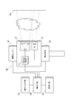
- FIG. 1 is a configuration block diagram of a gas detection system according to an embodiment of the present invention. It is a flowchart which shows the outline
- FIG. 6 shows a two-dimensional distribution of gas obtained by performing intermittent movement measurement (first measurement control) on the measurement object of FIG. 6 shows a two-dimensional distribution of gas obtained by performing continuous movement measurement (second measurement control) on the measurement object of FIG.
- first measurement control shows a two-dimensional distribution of gas obtained by performing intermittent movement measurement (first measurement control) on the measurement object of FIG. 6 shows a two-dimensional distribution of gas obtained by performing continuous movement measurement (second measurement control) on the measurement object of FIG.
- second measurement control shows the outline
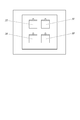
- a measurement unit 10 is installed with a space having a piping facility 100 as shown in FIG. 1A as a target area, and the measurement result includes two-dimensional gas distribution information as shown in FIG. 1B. Is to be output.
- the measurement unit 10 includes a light projecting unit 11, a light receiving unit 12, a light projecting / receiving control unit 13, a deflecting unit 14, and an environment sensor 15.
- the gas detection system includes a measurement unit 10, a control unit 20, a storage unit 21, and an operation input unit 22.
- the light projecting unit 11 emits laser light for detecting the surrounding gas toward the target area as measurement light.
- the light receiving unit 12 receives measurement light that is emitted from the light projecting unit 11 and reflected back by the background object 30 in the target area.
- the light projecting / receiving control unit 13 amplifies and A / D converts the light receiving signal from the light receiving unit 12 and the device element that drives and controls the light emission of the light projecting unit 11 based on the control command from the control unit 20 and inputs the control unit 20 It is described in one block for the sake of brevity.
- laser light having wavelengths of the target gas absorption band and non-absorption band is emitted from the measurement unit 10 (light projecting unit 11), passed through the same space, and reflected by a background object 30 such as a wall.
- control means 20 calculates the concentration-thickness product by taking the intensity ratio of the amount of received light between the absorption band and the non-absorption band based on the light reception signal input from the light projection / reception control unit 13. The method can be applied.
- the deflecting unit 14 deflects the measurement direction and moves the measurement point based on the control of the control unit 20.
- the deflecting unit 14 is an electric pan head that can move in a pan / tilt manner.
- the deflecting unit 14 is a mirror incorporated in a light projecting / receiving optical path in the measurement unit 10 such as a galvano mirror, and changes the reflection direction thereof. You may comprise by the element which the actuator accompanied.
- the environmental sensor 15 is an anemometer, a thermometer, a hygrometer, a barometer or the like, and the measured value is input to the control means 20.
- the control means 20 is configured and functions by executing a program on the CPU of the computer.
- the storage means 21 may be a storage device of the same computer or / and a storage device of another computer (server) that communicates information with the computer.
- the operation input means 22 may be an operation input device of the same computer or / and an operation input device of another computer (management computer) that communicates information with the computer. Examples of the operation input device include a keyboard, a mouse, and a touch panel, but the input method is not limited.
- the installation locations of the control means 20, the storage means 21, and the operation input means 22 are not particularly limited, such as inside or outside the measurement unit 10.
- the intermittent movement measurement (first measurement control) will be described with reference to the flowchart of FIG.
- the control unit 20 first generates a measurement path (S1).
- the measurement path is a rule that defines a path along which the measurement point is moved by the deflecting unit 14 and a stop position.
- the control means 20 calculates and generates a measurement path so that the scanning measurement of one surface of the measurement area is completed efficiently in a short time.
- command may be sufficient.
- the control means 20 executes intermittent movement measurement control (first measurement control) (S2-S5). That is, the control unit 20 controls the deflection unit 14 to move the measurement direction to the first measurement point determined in the measurement path (S2). Note that there is no actual movement if the measurement orientation is directed to the first measurement point. The movement is stopped at the measurement point (S3), and a light reception signal is acquired (S4).
- the control unit 20 associates the coordinates of each measurement point determined in the measurement path with the measurement value (concentration thickness product) at the measurement point to obtain two-dimensional distribution information.
- the generated two-dimensional distribution information is stored in the storage means 21. The above is a case where one two-dimensional scanning measurement is performed on one surface of the measurement area.
- the control unit 20 performs the movement intermittently by alternately providing the measurement point movement period and the stop period by the deflection unit 14. At the same time, by providing a period for detection by the light receiving unit 12 of the measurement light for gas detection during the stop period, the detection and the movement are alternately performed to obtain two-dimensional gas distribution information.
- Detection of measurement light for gas detection by the light receiving unit 12 refers to detection of measurement light corresponding to a received light signal that is input to the control means 20 via the light projection / reception control unit 13 and serves as a basis for measurement value calculation. .
- the continuous movement measurement (second measurement control) will be described with reference to the flowchart of FIG.
- the control unit 20 first generates a measurement path (S11).
- the measurement path is a rule that defines a path for moving the measurement point by the deflecting unit 14.
- the control means 20 calculates and generates a measurement path so that the scanning measurement of one surface of the measurement area is completed efficiently in a short time.
- command may be sufficient.
- the control means 20 executes continuous movement measurement control (second measurement control) (S12-S14). That is, the control unit 20 controls the deflection unit 14 to move the measurement direction to the measurement start point set in the measurement path (S12). It should be noted that there is no actual movement operation if the measurement direction is directed to the measurement start point.
- acquisition of the received light signal is started (S13). The acquisition of the received light signal is performed by dividing it into sampling periods of a certain time, and is executed on the assumption that one measurement value is calculated based on the received light signal in one sampling period. In some cases, an interval period is provided between the sampling period and the next sampling period.
- the control means 20 associates the coordinates of all the measurement points or representative measurement points (for example, the coordinates of the intermediate point) in each sampling period and the measurement value (concentration thickness product) based on the received light signal acquired in that sampling period.
- the generated two-dimensional distribution information is stored in the storage means 21.
- the above is a case where one two-dimensional scanning measurement is performed on one surface of the measurement area. Repeat the above process when measuring multiple times in succession.
- the control unit 20 continuously performs the movement of the measurement point by the deflecting unit 14, and during the movement of the measurement point by the deflecting unit 14, A period for detection by the light receiving unit 12 of the measurement light for detection is provided, and the detection is executed in parallel with the movement to obtain two-dimensional distribution information of the gas.
- Detection of measurement light for gas detection by the light receiving unit 12 refers to detection of measurement light corresponding to a received light signal that is input to the control means 20 via the light projection / reception control unit 13 and serves as a basis for measurement value calculation. .
- the gas detection system having the function of intermittent movement measurement described above, the form of the gas detection apparatus, the gas detection system having the function of continuous movement measurement, the form of the gas detection apparatus, and the function of intermittent movement measurement by the first measurement control
- the embodiment of the gas detection system and the gas detection device that can be executed by switching between the first measurement control and the second measurement control is implemented.
- a gas detection system and a gas detection device are provided that have an intermittent movement measurement function and a continuous movement measurement function, and are capable of performing both measurements simultaneously.
- FIG. 5 and 6A and 6B show experimental examples in which two-dimensional scanning measurement of gas is performed.
- a bag 31 in which the target gas is not sealed and three bags 32, 33, 34 in which the target gas is sealed at different concentrations are fixed to the wall, and the gas detection system of this embodiment is fixed.
- intermittent movement measurement first measurement control
- continuous movement measurement second measurement control
- 6A is a two-dimensional distribution of gas obtained by intermittent movement measurement
- FIG. 6B is a two-dimensional distribution of gas obtained by continuous movement measurement (second measurement control).
- the measured value is the concentration thickness product (ppm-m).
- the system includes a distance measuring unit that measures the distance to the background object 30.
- the distance measuring unit can be configured by measuring based on a time difference from the time when the control unit 20 causes the light projecting unit 11 to emit a predetermined signal to the time when the light receiving unit 12 receives the signal.
- an independent laser distance measuring device may be provided in the measurement unit 10 and the distance measurement value of the laser distance measuring device may be input to the control means 20.
- the control means 20 acquires measurement environment information (S21).
- the measurement environment information is a distance to the background object 30.
- the distance measured by the above distance measuring means may be used, or the distance input from the user when the user is requested to input the same distance.
- the control unit 20 executes the first measurement control (intermittent movement measurement) (S23), and in the other cases, the second measurement control. (Continuous movement measurement) is executed (S24).
- the intermittent movement measurement can be configured with high sensitivity because the received light signal is sampled and accumulated at a fixed point.
- the control means 20 acquires measurement environment information (S31).
- the measurement environment information is the angle of view of the measurement area.
- the control unit 20 executes the first measurement control (intermittent movement measurement) (S33), and in the other cases, the second measurement.
- Control continuous movement measurement
- the angle of view of the measurement area is relatively small, an embodiment in which high-sensitivity intermittent movement measurement is selected, and in the case where it is relatively large, time-priority continuous movement measurement is selected.
- the control means 20 acquires measurement environment information (S41).
- the measurement environment information is the wind speed input from the environment sensor 15.
- the control means 20 executes the first measurement control (intermittent movement measurement) (S43), and in the other cases, the second measurement control. (Continuous movement measurement) is executed (S44).
- the control unit 20 switches between the first measurement control and the second measurement control according to the measurement conditions.
- This measurement condition refers to the conditions of the measurement environment (distance, wind speed, etc.) and the conditions set in the apparatus (view angle, etc.).
- the control means 20 measures a predetermined target area set by the user by time-priority continuous movement measurement by the second measurement control. Then, there is an embodiment in which the sensitivity-priority intermittent movement measurement by the first measurement control is executed for the gas region detected in the predetermined target region according to the result. In this case, the control unit 20 specifies an area where the measurement value is equal to or greater than a predetermined threshold from the two-dimensional gas distribution obtained by the continuous movement measurement as a measurement area for the next intermittent movement measurement.
- the measuring direction is deflected by the deflecting means 14 in one movement period according to the distance measured by the distance measuring means.
- the control for changing the angle to be performed can be effectively performed.
- the control unit 20 performs control to change “the angle at which the measurement direction is deflected by the deflection unit 14 in one movement period” to be smaller as the distance is larger. Thereby, the gap space which is not measured can be suppressed small.
- Control can be implemented effectively.
- the control means 20 performs control (low-speed movement control) to change the angular velocity to be smaller as the distance is larger. Thereby, the remarkable fall of the measurement sensitivity with respect to a long-distance area
- the control means 20 determines the measurement area by calculating based on the measurement environment information instead of the user input.
- the control means 20 acquires the wind speed, the target gas type, and the pressure of the gas pipe in the target area as measurement environment information (S51).
- the wind speed is acquired by the environment sensor 15.
- the gas type and pressure are obtained by input from the user via the operation input means 22, or by collating position information such as GPS of the measurement point with the equipment database.
- the control means 20 estimates the gas diffusion rate based on the measurement environment information (S52).
- the control means 20 estimates the gas diffusion range based on the diffusion rate (S53).
- the control means 20 estimates a measurement area based on the diffusion range (S54).
- intermittent movement measurement can be performed by appropriately using the intermittent movement measurement method and the continuous movement measurement method or by configuring a gas detection device of both types.
- Control and continuous movement measurement (second measurement control) are appropriately switched and executed, whereby the gas can be measured efficiently and accurately.
- a continuous movement measurement type gas detection device is used for a wide area and at the same time a limited area in the wide area (such as a gas region detected by the continuous movement measurement type gas detection device). It is also possible to use an intermittent movement measurement type gas detector.
- the present invention can be used to detect gas.
Landscapes
- Physics & Mathematics (AREA)
- Engineering & Computer Science (AREA)
- Mathematical Physics (AREA)
- Theoretical Computer Science (AREA)
- Spectroscopy & Molecular Physics (AREA)
- Health & Medical Sciences (AREA)
- Life Sciences & Earth Sciences (AREA)
- Chemical & Material Sciences (AREA)
- Analytical Chemistry (AREA)
- Biochemistry (AREA)
- General Health & Medical Sciences (AREA)
- General Physics & Mathematics (AREA)
- Immunology (AREA)
- Pathology (AREA)
- Investigating Or Analysing Materials By Optical Means (AREA)
Abstract
投光部(11)と、受光部(12)と、測定方位を偏向して測定点を移動させる偏向手段(14)と、制御手段(20)とを備える。制御手段は、偏向手段による測定点の移動の期間と停止の期間とを交互に設けて当該移動を間欠的に実行するとともに、当該停止の期間にガス検知のための測定光の受光部による検出の期間を設けることにより、当該検出と当該移動とを交互に繰り返し実行しガスの2次元分布情報を得る(図6A)。制御手段は、偏向手段による測定点の移動を連続的に実行するとともに、偏向手段による測定点の移動中に、ガス検知のための測定光の受光部による検出の期間を設けて、当該検出を当該移動と並行に実行しガスの2次元分布情報を得る(図6B)。
Description
本発明は、レーザー光を走査して2次元的なガス分布を取得するガス検知システムに関する。
近年、ガス設備の老朽化や採掘現場のガスの漏えいが環境問題になっており、ガス漏えいの監視、ガス漏れ事故時のガス検知、ガス濃度分布の把握が求められている。
空間でガスを検出する方法としては、レーザー光による1点測定が知られている。この方法は、目的のガスの吸収帯と非吸収帯の波長のレーザー光を測定器から発して同じ空間に通し、壁などの任意の反射物に反射させて測定器に戻し、受光光量の強度比をみることで、ガス検知を行う。レーザー光の光路上に目的のガスが存在すれば、非吸収帯に対する吸収帯の強度比が低下するからである。
特許文献1-4に記載の発明にあっては、レーザー光による測定点を移動させて測定し、2元的なガス分布を得ようとする。
空間でガスを検出する方法としては、レーザー光による1点測定が知られている。この方法は、目的のガスの吸収帯と非吸収帯の波長のレーザー光を測定器から発して同じ空間に通し、壁などの任意の反射物に反射させて測定器に戻し、受光光量の強度比をみることで、ガス検知を行う。レーザー光の光路上に目的のガスが存在すれば、非吸収帯に対する吸収帯の強度比が低下するからである。
特許文献1-4に記載の発明にあっては、レーザー光による測定点を移動させて測定し、2元的なガス分布を得ようとする。
しかしながら、ガスを検知するためにレーザー光の二次元的な走査を行うと、全領域の計測に長時間を要するという問題がある。
反面、ガス検知のためのレーザー光の投受光期間(サンプリング期間)に投受光方向を偏向すると測定点(測定方位)が変わってしまい、検出感度の低下や、偏向移動速度のバラつきによる計測精度の低下という問題がある。
反面、ガス検知のためのレーザー光の投受光期間(サンプリング期間)に投受光方向を偏向すると測定点(測定方位)が変わってしまい、検出感度の低下や、偏向移動速度のバラつきによる計測精度の低下という問題がある。
本発明は以上の従来技術における問題に鑑みてなされたものであって、レーザー光を走査して2次元的なガス分布を取得するガス検知システムにおいて、効率良く高精度にガスを測定することを課題とする。
以上の課題を解決するための請求項1記載の発明は、周囲のガスを検知するためのレーザー光を測定光として対象域に向けて出射する投光部と、
前記投光部から出射し対象域の背景物体により反射して戻ってくる測定光を受光する受光部と、を備え前記受光部で受光した受光信号に基づきガスを検知するガス検知システムにおいて、
測定方位を偏向して測定点を移動させる偏向手段と、制御手段と、を備え、
前記制御手段は、前記偏向手段による前記測定点の移動の期間と停止の期間とを交互に設けて当該移動を間欠的に実行するとともに、当該停止の期間にガス検知のための前記測定光の前記受光部による検出の期間を設けることにより、当該検出と当該移動とを交互に繰り返し実行しガスの2次元分布情報を得るガス検知システムである。
前記投光部から出射し対象域の背景物体により反射して戻ってくる測定光を受光する受光部と、を備え前記受光部で受光した受光信号に基づきガスを検知するガス検知システムにおいて、
測定方位を偏向して測定点を移動させる偏向手段と、制御手段と、を備え、
前記制御手段は、前記偏向手段による前記測定点の移動の期間と停止の期間とを交互に設けて当該移動を間欠的に実行するとともに、当該停止の期間にガス検知のための前記測定光の前記受光部による検出の期間を設けることにより、当該検出と当該移動とを交互に繰り返し実行しガスの2次元分布情報を得るガス検知システムである。
請求項2記載の発明は、周囲のガスを検知するためのレーザー光を測定光として対象域に向けて出射する投光部と、
前記投光部から出射し対象域の背景物体により反射して戻ってくる測定光を受光する受光部と、を備え前記受光部で受光した光の受光信号に基づきガスを検知するガス検知システムにおいて、
測定方位を偏向して測定点を移動させる偏向手段と、制御手段と、を備え、
前記制御手段は、前記偏向手段による前記測定点の移動を連続的に実行するとともに、前記偏向手段による前記測定点の移動中に、ガス検知のための前記測定光の前記受光部による検出の期間を設けて、当該検出を当該移動と並行に実行しガスの2次元分布情報を得るガス検知システムである。
前記投光部から出射し対象域の背景物体により反射して戻ってくる測定光を受光する受光部と、を備え前記受光部で受光した光の受光信号に基づきガスを検知するガス検知システムにおいて、
測定方位を偏向して測定点を移動させる偏向手段と、制御手段と、を備え、
前記制御手段は、前記偏向手段による前記測定点の移動を連続的に実行するとともに、前記偏向手段による前記測定点の移動中に、ガス検知のための前記測定光の前記受光部による検出の期間を設けて、当該検出を当該移動と並行に実行しガスの2次元分布情報を得るガス検知システムである。
請求項3記載の発明は、周囲のガスを検知するためのレーザー光を測定光として対象域に向けて出射する投光部と、
前記投光部から出射し対象域の背景物体により反射して戻ってくる測定光を受光する受光部と、を備え前記受光部で受光した受光信号に基づきガスを検知するガス検知システムにおいて、
測定方位を偏向して測定点を移動させる偏向手段と、制御手段と、を備え、
前記制御手段は、
前記偏向手段による前記測定点の移動の期間と停止の期間とを交互に設けて当該移動を間欠的に実行するとともに、当該停止の期間にガス検知のための前記測定光の前記受光部による検出の期間を設けることにより、当該検出と当該移動とを交互に繰り返し実行しガスの2次元分布情報を得る第1の測定制御と、
前記偏向手段による前記測定点の移動を連続的に実行するとともに、前記偏向手段による前記測定点の移動中に、ガス検知のための前記測定光の前記受光部による検出の期間を設けて、当該検出を当該移動と並行に実行しガスの2次元分布情報を得る第2の測定制御と、を切り替えて実行可能であるガス検知システムである。
前記投光部から出射し対象域の背景物体により反射して戻ってくる測定光を受光する受光部と、を備え前記受光部で受光した受光信号に基づきガスを検知するガス検知システムにおいて、
測定方位を偏向して測定点を移動させる偏向手段と、制御手段と、を備え、
前記制御手段は、
前記偏向手段による前記測定点の移動の期間と停止の期間とを交互に設けて当該移動を間欠的に実行するとともに、当該停止の期間にガス検知のための前記測定光の前記受光部による検出の期間を設けることにより、当該検出と当該移動とを交互に繰り返し実行しガスの2次元分布情報を得る第1の測定制御と、
前記偏向手段による前記測定点の移動を連続的に実行するとともに、前記偏向手段による前記測定点の移動中に、ガス検知のための前記測定光の前記受光部による検出の期間を設けて、当該検出を当該移動と並行に実行しガスの2次元分布情報を得る第2の測定制御と、を切り替えて実行可能であるガス検知システムである。
請求項4記載の発明は、前記制御手段は、測定条件に応じて、前記第1の測定制御と前記第2の測定制御とを切り替える請求項3に記載のガス検知システムである。
請求項5記載の発明は、前記測定条件は、前記背景物体までの距離、測定エリアの画角、風速のいずれか一つを含む請求項4に記載のガス検知システムである。
請求項6記載の発明は、前記制御手段は、所定の対象域を前記第2の測定制御により測定し、その結果により前記所定の対象域内に検知したガス領域を対象に前記第1の測定制御による測定を実行する請求項3に記載のガス検知システムである。
請求項7記載の発明は、前記背景物体までの距離を測定する距離測定手段を備え、前記制御手段は、前記距離測定手段が測定する距離に応じて、一の移動の期間で前記偏向手段により測定方位を偏向する角度を変更する請求項1に記載のガス検知システムである。
請求項8記載の発明は、前記背景物体までの距離を測定する距離測定手段を備え、前記制御手段は、前記距離測定手段が測定する距離に応じて、前記偏向手段により測定方位を偏向する角速度を変更する請求項2に記載のガス検知システムである。
請求項9記載の発明は、前記背景物体までの距離を測定する距離測定手段を備え、前記制御手段は、第1の測定制御において前記距離測定手段が測定する距離に応じて、一の移動の期間で前記偏向手段により測定方位を偏向する角度を変更し、第2の測定制御において前記距離測定手段が測定する距離に応じて、前記偏向手段により測定方位を偏向する角速度を変更する請求項3に記載のガス検知システムである。
本発明によれば、レーザー光を走査して2次元的なガス分布を取得するガス検知システムにおいて、間欠移動測定(第1の測定制御)と連続移動測定(第2の測定制御)とを目的、条件等に応じて使い分けたり、切り替えて実行したりすることで、効率良く高精度にガスを測定することができる。
以下に本発明の一実施形態につき図面を参照して説明する。以下は本発明の一実施形態であって本発明を限定するものではない。
本実施形態のガス検知システムは、例えば、図1Aに示すような配管設備100のある空間を対象域として測定ユニット10を設置し、図1Bに示すようなガスの2次元分布情報を含む測定結果を出力しようとするものである。
図2に示すように測定ユニット10は、投光部11と、受光部12と、投受光制御部13と、偏向手段14と、環境センサー15とを備える。
本ガス検知システムは、測定ユニット10と、制御手段20と、記憶手段21と、操作入力手段22とを備える。
投光部11は、周囲のガスを検出するためのレーザー光を測定光として対象域に向けて出射する。
受光部12は、投光部11から出射し対象域の背景物体30により反射して戻ってくる測定光を受光する。
投受光制御部13は、制御手段20からの制御指令に基づき投光部11の発光を駆動制御する装置要素と、受光部12による受光信号を増幅、A/D変換して制御手段20に入力する装置要素に相当し、簡潔のため1ブロックで記載したものである。
ガスの測定方式としては、目的のガスの吸収帯と非吸収帯の波長のレーザー光を測定ユニット10(投光部11)から発して同じ空間に通し、壁などの背景物体30に反射させて測定ユニット10(受光部12)に戻し、投受光制御部13から入力される受光信号に基づき制御手段20が、吸収帯と非吸収帯の受光光量の強度比をとって濃度厚み積を算出する方式を適用できる。
本ガス検知システムは、測定ユニット10と、制御手段20と、記憶手段21と、操作入力手段22とを備える。
投光部11は、周囲のガスを検出するためのレーザー光を測定光として対象域に向けて出射する。
受光部12は、投光部11から出射し対象域の背景物体30により反射して戻ってくる測定光を受光する。
投受光制御部13は、制御手段20からの制御指令に基づき投光部11の発光を駆動制御する装置要素と、受光部12による受光信号を増幅、A/D変換して制御手段20に入力する装置要素に相当し、簡潔のため1ブロックで記載したものである。
ガスの測定方式としては、目的のガスの吸収帯と非吸収帯の波長のレーザー光を測定ユニット10(投光部11)から発して同じ空間に通し、壁などの背景物体30に反射させて測定ユニット10(受光部12)に戻し、投受光制御部13から入力される受光信号に基づき制御手段20が、吸収帯と非吸収帯の受光光量の強度比をとって濃度厚み積を算出する方式を適用できる。
偏向手段14は、制御手段20の制御に基づき、測定方位を偏向して測定点を移動させる。偏向手段14は、本実施形態では、パン・チルト移動が可能な電動雲台であるが、ガルバノミラーなど、測定ユニット10内の投受光光路に組み込まれたミラーであってその反射方向を変更するアクチュエーターが付随した要素によって構成してもよい。
環境センサー15は、風速計、温度計、湿度計、気圧計などであって、その計測値は制御手段20に入力される。
環境センサー15は、風速計、温度計、湿度計、気圧計などであって、その計測値は制御手段20に入力される。
制御手段20は、コンピューターのCPUでのプログラムの実行により構成され機能する。
記憶手段21は、同コンピューターの記憶装置か又は/及び同コンピューターと情報通信する他のコンピューター(サーバー)の記憶装置が想定される。
操作入力手段22は、同コンピューターの操作入力装置又は/及び同コンピューターと情報通信する他のコンピューター(管理コンピューター)の操作入力装置が想定される。操作入力装置の例としては、キーボード、マウス、タッチパネルを挙げることができるが、入力方式は問わない。
これらの制御手段20、記憶手段21及び操作入力手段22の設置場所は、測定ユニット10の内部や外部など特に限定されるものではない。
記憶手段21は、同コンピューターの記憶装置か又は/及び同コンピューターと情報通信する他のコンピューター(サーバー)の記憶装置が想定される。
操作入力手段22は、同コンピューターの操作入力装置又は/及び同コンピューターと情報通信する他のコンピューター(管理コンピューター)の操作入力装置が想定される。操作入力装置の例としては、キーボード、マウス、タッチパネルを挙げることができるが、入力方式は問わない。
これらの制御手段20、記憶手段21及び操作入力手段22の設置場所は、測定ユニット10の内部や外部など特に限定されるものではない。
間欠移動測定(第1の測定制御)につき図3のフローチャートを参照して説明する。
操作入力手段22を介したユーザーからの入力により測定エリア、移動ピッチ等の測定条件が設定され測定開始指令が入力されると、まず、制御手段20は測定パスを生成する(S1)。測定パスとは、偏向手段14よって測定点を移動させる経路と停止位置を定めたルールである。制御手段20は効率よく短時間で測定エリアの一面の走査測定が終了するように測定パスを演算し生成する。なお、ユーザーからの測定パス生成指令を受けて制御手段20が測定パスを生成し、その後の測定開始指令の入力により測定動作を開始する手順でもよい。
次に、制御手段20は間欠移動測定の制御(第1の測定制御)を実行する(S2-S5)。
すなわち、制御手段20は偏向手段14を制御して測定方位を、測定パスに定められた初めの測定点まで移動させる(S2)。なお、測定方位が初めの測定点に向いていれば実際の移動動作はない。
測定点で移動を停止し(S3)、受光信号を取得する(S4)。さらに測定パスに定められた次の測定点に移動して停止し受光信号を取得する(S5でNO→S2→S3→S4)。測定パスに定められた測定点が無くなるまで、これを繰り返す。
最後の測定点での受光信号の取得が完了すると(ステップS5でYES)、以上の2次元走査測定の結果、すなわち、ガスの2次元分布情報を生成し出力する(S6)。制御手段20は、測定パスに定められた各測定点の座標と、その測定点での測定値(濃度厚み積)とを結び付けて2次元分布情報とする。生成した2次元分布情報を記憶手段21に保存する。
以上は、測定エリアの一面に対し一回の2次元走査測定をする場合で説明している。続けて複数回測定する場合は、以上の過程を繰り返す。
以上のように、間欠移動測定(第1の測定制御)では、制御手段20は、偏向手段14による測定点の移動の期間と停止の期間とを交互に設けて当該移動を間欠的に実行するとともに、当該停止の期間にガス検知のための測定光の受光部12による検出の期間を設けることにより、当該検出と当該移動とを交互に繰り返し実行しガスの2次元分布情報を得る。「ガス検知のための測定光の受光部12による検出」とは、投受光制御部13を介して制御手段20に入力され測定値演算の基礎となる受光信号の分の測定光の検出を指す。
操作入力手段22を介したユーザーからの入力により測定エリア、移動ピッチ等の測定条件が設定され測定開始指令が入力されると、まず、制御手段20は測定パスを生成する(S1)。測定パスとは、偏向手段14よって測定点を移動させる経路と停止位置を定めたルールである。制御手段20は効率よく短時間で測定エリアの一面の走査測定が終了するように測定パスを演算し生成する。なお、ユーザーからの測定パス生成指令を受けて制御手段20が測定パスを生成し、その後の測定開始指令の入力により測定動作を開始する手順でもよい。
次に、制御手段20は間欠移動測定の制御(第1の測定制御)を実行する(S2-S5)。
すなわち、制御手段20は偏向手段14を制御して測定方位を、測定パスに定められた初めの測定点まで移動させる(S2)。なお、測定方位が初めの測定点に向いていれば実際の移動動作はない。
測定点で移動を停止し(S3)、受光信号を取得する(S4)。さらに測定パスに定められた次の測定点に移動して停止し受光信号を取得する(S5でNO→S2→S3→S4)。測定パスに定められた測定点が無くなるまで、これを繰り返す。
最後の測定点での受光信号の取得が完了すると(ステップS5でYES)、以上の2次元走査測定の結果、すなわち、ガスの2次元分布情報を生成し出力する(S6)。制御手段20は、測定パスに定められた各測定点の座標と、その測定点での測定値(濃度厚み積)とを結び付けて2次元分布情報とする。生成した2次元分布情報を記憶手段21に保存する。
以上は、測定エリアの一面に対し一回の2次元走査測定をする場合で説明している。続けて複数回測定する場合は、以上の過程を繰り返す。
以上のように、間欠移動測定(第1の測定制御)では、制御手段20は、偏向手段14による測定点の移動の期間と停止の期間とを交互に設けて当該移動を間欠的に実行するとともに、当該停止の期間にガス検知のための測定光の受光部12による検出の期間を設けることにより、当該検出と当該移動とを交互に繰り返し実行しガスの2次元分布情報を得る。「ガス検知のための測定光の受光部12による検出」とは、投受光制御部13を介して制御手段20に入力され測定値演算の基礎となる受光信号の分の測定光の検出を指す。
連続移動測定(第2の測定制御)につき図4のフローチャートを参照して説明する。
操作入力手段22を介したユーザーからの入力により測定エリア、移動ピッチ等の測定条件が設定され測定開始指令が入力されると、まず、制御手段20は測定パスを生成する(S11)。測定パスとは、偏向手段14よって測定点を移動させる経路を定めたルールである。制御手段20は効率よく短時間で測定エリアの一面の走査測定が終了するように測定パスを演算し生成する。なお、ユーザーからの測定パス生成指令を受けて制御手段20が測定パスを生成し、その後の測定開始指令の入力により測定動作を開始する手順でもよい。
次に、制御手段20は連続移動測定の制御(第2の測定制御)を実行する(S12-S14)。
すなわち、制御手段20は偏向手段14を制御して測定方位を、測定パスに定められた測定開始点まで移動させる(S12)。なお、測定方位が測定開始点に向いていれば実際の移動動作はない。
測定開始点に移動したら、受光信号の取得を開始する(S13)。受光信号の取得は一定時間のサンプリング期間に区切って行い、一サンプリング期間での受光信号に基づき一測定値を算出するものとして実行する。サンプリング期間と次のサンプリング期間との間にインターバル期間が設けられる場合もある。サンプリング期間中もインターバル期間中も測定点は移動するので、インターバル期間が無いか、全期間に対するサンプリング期間が占める割合が大きくなるように設計することが好ましい。
測定パスに定められた測定終了点に達したら(ステップS14でYES)、受光信号の取得が完了されたので移動を停止する(S15)。なお、測定開始点やその他の待機位置に戻って停止する制御としてもよい。
以上の2次元走査測定の結果、すなわち、ガスの2次元分布情報を生成し出力する(S16)。制御手段20は、各サンプリング期間におけるすべての測定点又は代表の測定点の座標(例えば中間点の座標)と、そのサンプリング期間で取得した受光信号に基づく測定値(濃度厚み積)とを結び付けて2次元分布情報とする。生成した2次元分布情報を記憶手段21に保存する。
以上は、測定エリアの一面に対し一回の2次元走査測定をする場合で説明している。続けて複数回測定する場合は、以上の過程を繰り返す。
以上のように、連続移動測定(第2の測定制御)では、制御手段20は、偏向手段14による測定点の移動を連続的に実行するとともに、偏向手段14による測定点の移動中に、ガス検知のための測定光の受光部12による検出の期間を設けて、当該検出を当該移動と並行に実行しガスの2次元分布情報を得る。「ガス検知のための測定光の受光部12による検出」とは、投受光制御部13を介して制御手段20に入力され測定値演算の基礎となる受光信号の分の測定光の検出を指す。
操作入力手段22を介したユーザーからの入力により測定エリア、移動ピッチ等の測定条件が設定され測定開始指令が入力されると、まず、制御手段20は測定パスを生成する(S11)。測定パスとは、偏向手段14よって測定点を移動させる経路を定めたルールである。制御手段20は効率よく短時間で測定エリアの一面の走査測定が終了するように測定パスを演算し生成する。なお、ユーザーからの測定パス生成指令を受けて制御手段20が測定パスを生成し、その後の測定開始指令の入力により測定動作を開始する手順でもよい。
次に、制御手段20は連続移動測定の制御(第2の測定制御)を実行する(S12-S14)。
すなわち、制御手段20は偏向手段14を制御して測定方位を、測定パスに定められた測定開始点まで移動させる(S12)。なお、測定方位が測定開始点に向いていれば実際の移動動作はない。
測定開始点に移動したら、受光信号の取得を開始する(S13)。受光信号の取得は一定時間のサンプリング期間に区切って行い、一サンプリング期間での受光信号に基づき一測定値を算出するものとして実行する。サンプリング期間と次のサンプリング期間との間にインターバル期間が設けられる場合もある。サンプリング期間中もインターバル期間中も測定点は移動するので、インターバル期間が無いか、全期間に対するサンプリング期間が占める割合が大きくなるように設計することが好ましい。
測定パスに定められた測定終了点に達したら(ステップS14でYES)、受光信号の取得が完了されたので移動を停止する(S15)。なお、測定開始点やその他の待機位置に戻って停止する制御としてもよい。
以上の2次元走査測定の結果、すなわち、ガスの2次元分布情報を生成し出力する(S16)。制御手段20は、各サンプリング期間におけるすべての測定点又は代表の測定点の座標(例えば中間点の座標)と、そのサンプリング期間で取得した受光信号に基づく測定値(濃度厚み積)とを結び付けて2次元分布情報とする。生成した2次元分布情報を記憶手段21に保存する。
以上は、測定エリアの一面に対し一回の2次元走査測定をする場合で説明している。続けて複数回測定する場合は、以上の過程を繰り返す。
以上のように、連続移動測定(第2の測定制御)では、制御手段20は、偏向手段14による測定点の移動を連続的に実行するとともに、偏向手段14による測定点の移動中に、ガス検知のための測定光の受光部12による検出の期間を設けて、当該検出を当該移動と並行に実行しガスの2次元分布情報を得る。「ガス検知のための測定光の受光部12による検出」とは、投受光制御部13を介して制御手段20に入力され測定値演算の基礎となる受光信号の分の測定光の検出を指す。
以上説明した間欠移動測定の機能を備えたガス検知システム、ガス検知装置の形態、連続移動測定の機能を備えたガス検知システム、ガス検知装置の形態、第1の測定制御により間欠移動測定の機能を実現するとともに第2の測定制御による連続移動測定の機能を実現し、第1の測定制御と第2の測定制御とを切り替えて実行可能であるガス検知システム、ガス検知装置の形態を実施する。
また、間欠移動測定の機能及び連続移動測定の機能を備え、両測定を同時に実行可能であるガス検知システム、ガス検知装置の形態を実施する。
また、間欠移動測定の機能及び連続移動測定の機能を備え、両測定を同時に実行可能であるガス検知システム、ガス検知装置の形態を実施する。
図5及び図6A,6Bは、ガスの2次元走査測定を実施した実験例を示す。
図5に示すように壁に、目的のガスを封入していない袋31と、目的のガスを濃度を変えて封入した3つの袋32,33,34を固定し、本実施形態のガス検知システムにより間欠移動測定(第1の測定制御)と連続移動測定(第2の測定制御)とを実施した。図6Aは、間欠移動測定(第1の測定制御)により得られたガスの2次元分布であり、図6Bは、連続移動測定(第2の測定制御)により得られたガスの2次元分布であり、測定値は濃度厚み積(ppm-m)である。
図5に示すように壁に、目的のガスを封入していない袋31と、目的のガスを濃度を変えて封入した3つの袋32,33,34を固定し、本実施形態のガス検知システムにより間欠移動測定(第1の測定制御)と連続移動測定(第2の測定制御)とを実施した。図6Aは、間欠移動測定(第1の測定制御)により得られたガスの2次元分布であり、図6Bは、連続移動測定(第2の測定制御)により得られたガスの2次元分布であり、測定値は濃度厚み積(ppm-m)である。
次に、第1の測定制御と第2の測定制御との切り替え制御と、偏向角、角速度の制御の例について説明する。
本システムは、背景物体30までの距離を測定する距離測定手段を備える。距離測定手段は、制御手段20が、所定の信号を投光部11により発光させた時点から、同信号を受光部12で受信した時点までの時差に基づき測定することで構成できる。又は、独立したレーザー測距装置を測定ユニット10に設けて、そのレーザー測距装置の距離測定値を制御手段20に入力するようにして実施してもよい。
本システムは、背景物体30までの距離を測定する距離測定手段を備える。距離測定手段は、制御手段20が、所定の信号を投光部11により発光させた時点から、同信号を受光部12で受信した時点までの時差に基づき測定することで構成できる。又は、独立したレーザー測距装置を測定ユニット10に設けて、そのレーザー測距装置の距離測定値を制御手段20に入力するようにして実施してもよい。
図7Aに示すように、制御手段20は、測定環境情報を取得する(S21)。ここでは、測定環境情報は背景物体30までの距離である。上記の距離測定手段により測定された距離でもよいし、ユーザーに同距離の入力を要求してユーザーから入力された距離でもよい。
制御手段20は、当該距離が所定の閾値より大きいと判断する場合(ステップS22でYES)、第1の測定制御(間欠移動測定)を実行し(S23)、他の場合は第2の測定制御(連続移動測定)を実行する(S24)。間欠移動測定は、定点で受光信号をサンプリングし蓄積するため、高感度に構成することができる。連続移動測定は一定点に対するサンプリングが希薄になりやすいが測定エリア一面の走査時間を短時間にすることができる。設計にもよるが、間欠移動測定を感度優先な設計、連続移動測定を時間優先の設計にしている場合において、背景物体30までの距離が比較的遠い場合は、高感度な間欠移動測定を選択し、比較的近い場合には時間優先の連続移動測定を選択する実施形態をとることができる。
制御手段20は、当該距離が所定の閾値より大きいと判断する場合(ステップS22でYES)、第1の測定制御(間欠移動測定)を実行し(S23)、他の場合は第2の測定制御(連続移動測定)を実行する(S24)。間欠移動測定は、定点で受光信号をサンプリングし蓄積するため、高感度に構成することができる。連続移動測定は一定点に対するサンプリングが希薄になりやすいが測定エリア一面の走査時間を短時間にすることができる。設計にもよるが、間欠移動測定を感度優先な設計、連続移動測定を時間優先の設計にしている場合において、背景物体30までの距離が比較的遠い場合は、高感度な間欠移動測定を選択し、比較的近い場合には時間優先の連続移動測定を選択する実施形態をとることができる。
図7Bに示すように、制御手段20は、測定環境情報を取得する(S31)。ここでは、測定環境情報は測定エリアの画角である。
制御手段20は、当該画角が所定の閾値より小さいと判断する場合(ステップS32でYES)、第1の測定制御(間欠移動測定)を実行し(S33)、他の場合は第2の測定制御(連続移動測定)を実行する(S34)。測定エリアの画角が比較的小さい場合は、高感度な間欠移動測定を選択し、比較的大きい場合は時間優先の連続移動測定を選択する実施形態をとることができる。
制御手段20は、当該画角が所定の閾値より小さいと判断する場合(ステップS32でYES)、第1の測定制御(間欠移動測定)を実行し(S33)、他の場合は第2の測定制御(連続移動測定)を実行する(S34)。測定エリアの画角が比較的小さい場合は、高感度な間欠移動測定を選択し、比較的大きい場合は時間優先の連続移動測定を選択する実施形態をとることができる。
図7Cに示すように、制御手段20は、測定環境情報を取得する(S41)。ここでは、測定環境情報は環境センサー15から入力された風速である。
制御手段20は、当該風速が所定の閾値より大きいと判断する場合(ステップS42でYES)、第1の測定制御(間欠移動測定)を実行し(S43)、他の場合は第2の測定制御(連続移動測定)を実行する(S44)。風速が比較的大きい場合は、高感度な間欠移動測定を選択し、比較的小さい場合は時間優先の連続移動測定を選択する実施形態をとることができる。
例えば以上のようにして制御手段20は、測定条件に応じて、第1の測定制御と第2の測定制御とを切り替える。この測定条件は、測定環境の条件(距離、風速など)及び装置に設定される条件(画角など)を指す。
制御手段20は、当該風速が所定の閾値より大きいと判断する場合(ステップS42でYES)、第1の測定制御(間欠移動測定)を実行し(S43)、他の場合は第2の測定制御(連続移動測定)を実行する(S44)。風速が比較的大きい場合は、高感度な間欠移動測定を選択し、比較的小さい場合は時間優先の連続移動測定を選択する実施形態をとることができる。
例えば以上のようにして制御手段20は、測定条件に応じて、第1の測定制御と第2の測定制御とを切り替える。この測定条件は、測定環境の条件(距離、風速など)及び装置に設定される条件(画角など)を指す。
また、第1の測定制御と第2の測定制御とを切り替える実施形態としては、制御手段20が、ユーザーにより設定される所定の対象域を第2の測定制御による時間優先の連続移動測定で測定し、その結果により前記所定の対象域内に検知したガス領域を対象に第1の測定制御による感度優先の間欠移動測定を実行する実施形態が挙げられる。この場合、制御手段20は、連続移動測定により取得したガスの2次元分布から測定値が所定の閾値以上であるエリアをガス領域として特定し、これを次の間欠移動測定の測定エリアとする。
図7Aのように距離を取得するとともに第1の測定制御(間欠移動測定)を実行する場合、距離測定手段が測定する距離に応じて、一の移動の期間で偏向手段14により測定方位を偏向する角度を変更する制御を有効に実施することができる。
例えば制御手段20は、当該距離が大きいほど、「一の移動の期間で偏向手段14により測定方位を偏向する角度」を小さく変更する制御を実施する。これにより、測定されない隙間空間を小さく抑えることができる。
また図7Aのように距離を取得するとともに第2の測定制御(連続移動測定)を実行する場合、距離測定手段が測定する距離に応じて、偏向手段14により測定方位を偏向する角速度を変更する制御を有効に実施することができる。
例えば制御手段20は、当該距離が大きいほど、当該角速度を小さく変更する制御(低速移動制御)を実施する。これにより、遠距離領域に対する測定感度の著しい低下を抑えることができる。
例えば制御手段20は、当該距離が大きいほど、「一の移動の期間で偏向手段14により測定方位を偏向する角度」を小さく変更する制御を実施する。これにより、測定されない隙間空間を小さく抑えることができる。
また図7Aのように距離を取得するとともに第2の測定制御(連続移動測定)を実行する場合、距離測定手段が測定する距離に応じて、偏向手段14により測定方位を偏向する角速度を変更する制御を有効に実施することができる。
例えば制御手段20は、当該距離が大きいほど、当該角速度を小さく変更する制御(低速移動制御)を実施する。これにより、遠距離領域に対する測定感度の著しい低下を抑えることができる。
次に測定エリアの決定方法につき図8を参照して説明する。
ユーザー入力ではなく制御手段20が測定環境情報に基づき演算して測定エリアを決定する方法である。
まず制御手段20は、測定環境情報として、風速、目的のガス種、対象域にあるガス配管の圧力を取得する(S51)。風速は環境センサー15により取得する。ガス種や圧力は、操作入力手段22を介したユーザーからの入力によるか、又は測定地点のGPS等による位置情報と設備データベースとを照合して取得する。
次に制御手段20は、上記測定環境情報に基づきガスの拡散速度を推定する(S52)。
次に制御手段20は、上記拡散速度に基づきガスの拡散範囲を推定する(S53)。
次に制御手段20は、上記拡散範囲に基づき測定エリアを推定する(S54)。
ユーザー入力ではなく制御手段20が測定環境情報に基づき演算して測定エリアを決定する方法である。
まず制御手段20は、測定環境情報として、風速、目的のガス種、対象域にあるガス配管の圧力を取得する(S51)。風速は環境センサー15により取得する。ガス種や圧力は、操作入力手段22を介したユーザーからの入力によるか、又は測定地点のGPS等による位置情報と設備データベースとを照合して取得する。
次に制御手段20は、上記測定環境情報に基づきガスの拡散速度を推定する(S52)。
次に制御手段20は、上記拡散速度に基づきガスの拡散範囲を推定する(S53)。
次に制御手段20は、上記拡散範囲に基づき測定エリアを推定する(S54)。
以上のようにして本実施形態によれば、間欠移動測定方式と連続移動測定方式とを適宜使い分けすることにより、又は両方式切替式のガス検知装置を構成して間欠移動測定(第1の測定制御)と連続移動測定(第2の測定制御)とを適宜切り替えて実行することで、効率良く高精度にガスを測定することができる。例えば、連続移動測定方式のガス検知装置を広域エリアを対象に使用すると同時に、その広域エリア中の限定されたエリア(同連続移動測定方式のガス検知装置により検知されたガス領域など)を対象に間欠移動測定方式のガス検知装置を使用することも可能である。
本発明は、ガスを検知することに利用することができる。
10 測定ユニット
11 投光部
12 受光部
13 投受光制御部
14 偏向手段
15 環境センサー
20 制御手段
21 記憶手段
22 操作入力手段
30 背景物体
100 配管設備
11 投光部
12 受光部
13 投受光制御部
14 偏向手段
15 環境センサー
20 制御手段
21 記憶手段
22 操作入力手段
30 背景物体
100 配管設備
Claims (9)
- 周囲のガスを検知するためのレーザー光を測定光として対象域に向けて出射する投光部と、
前記投光部から出射し対象域の背景物体により反射して戻ってくる測定光を受光する受光部と、を備え前記受光部で受光した受光信号に基づきガスを検知するガス検知システムにおいて、
測定方位を偏向して測定点を移動させる偏向手段と、制御手段と、を備え、
前記制御手段は、前記偏向手段による前記測定点の移動の期間と停止の期間とを交互に設けて当該移動を間欠的に実行するとともに、当該停止の期間にガス検知のための前記測定光の前記受光部による検出の期間を設けることにより、当該検出と当該移動とを交互に繰り返し実行しガスの2次元分布情報を得るガス検知システム。 - 周囲のガスを検知するためのレーザー光を測定光として対象域に向けて出射する投光部と、
前記投光部から出射し対象域の背景物体により反射して戻ってくる測定光を受光する受光部と、を備え前記受光部で受光した光の受光信号に基づきガスを検知するガス検知システムにおいて、
測定方位を偏向して測定点を移動させる偏向手段と、制御手段と、を備え、
前記制御手段は、前記偏向手段による前記測定点の移動を連続的に実行するとともに、前記偏向手段による前記測定点の移動中に、ガス検知のための前記測定光の前記受光部による検出の期間を設けて、当該検出を当該移動と並行に実行しガスの2次元分布情報を得るガス検知システム。 - 周囲のガスを検知するためのレーザー光を測定光として対象域に向けて出射する投光部と、
前記投光部から出射し対象域の背景物体により反射して戻ってくる測定光を受光する受光部と、を備え前記受光部で受光した受光信号に基づきガスを検知するガス検知システムにおいて、
測定方位を偏向して測定点を移動させる偏向手段と、制御手段と、を備え、
前記制御手段は、
前記偏向手段による前記測定点の移動の期間と停止の期間とを交互に設けて当該移動を間欠的に実行するとともに、当該停止の期間にガス検知のための前記測定光の前記受光部による検出の期間を設けることにより、当該検出と当該移動とを交互に繰り返し実行しガスの2次元分布情報を得る第1の測定制御と、
前記偏向手段による前記測定点の移動を連続的に実行するとともに、前記偏向手段による前記測定点の移動中に、ガス検知のための前記測定光の前記受光部による検出の期間を設けて、当該検出を当該移動と並行に実行しガスの2次元分布情報を得る第2の測定制御と、を切り替えて実行可能であるガス検知システム。 - 前記制御手段は、測定条件に応じて、前記第1の測定制御と前記第2の測定制御とを切り替える請求項3に記載のガス検知システム。
- 前記測定条件は、前記背景物体までの距離、測定エリアの画角、風速のいずれか一つを含む請求項4に記載のガス検知システム。
- 前記制御手段は、所定の対象域を前記第2の測定制御により測定し、その結果により前記所定の対象域内に検知したガス領域を対象に前記第1の測定制御による測定を実行する請求項3に記載のガス検知システム。
- 前記背景物体までの距離を測定する距離測定手段を備え、前記制御手段は、前記距離測定手段が測定する距離に応じて、一の移動の期間で前記偏向手段により測定方位を偏向する角度を変更する請求項1に記載のガス検知システム。
- 前記背景物体までの距離を測定する距離測定手段を備え、前記制御手段は、前記距離測定手段が測定する距離に応じて、前記偏向手段により測定方位を偏向する角速度を変更する請求項2に記載のガス検知システム。
- 前記背景物体までの距離を測定する距離測定手段を備え、前記制御手段は、第1の測定制御において前記距離測定手段が測定する距離に応じて、一の移動の期間で前記偏向手段により測定方位を偏向する角度を変更し、第2の測定制御において前記距離測定手段が測定する距離に応じて、前記偏向手段により測定方位を偏向する角速度を変更する請求項3に記載のガス検知システム。
Applications Claiming Priority (2)
| Application Number | Priority Date | Filing Date | Title |
|---|---|---|---|
| JP2016-143981 | 2016-07-22 | ||
| JP2016143981A JP2019152435A (ja) | 2016-07-22 | 2016-07-22 | ガス検知システム |
Publications (1)
| Publication Number | Publication Date |
|---|---|
| WO2018016447A1 true WO2018016447A1 (ja) | 2018-01-25 |
Family
ID=60992504
Family Applications (1)
| Application Number | Title | Priority Date | Filing Date |
|---|---|---|---|
| PCT/JP2017/025795 Ceased WO2018016447A1 (ja) | 2016-07-22 | 2017-07-14 | ガス検知システム |
Country Status (2)
| Country | Link |
|---|---|
| JP (1) | JP2019152435A (ja) |
| WO (1) | WO2018016447A1 (ja) |
Cited By (1)
| Publication number | Priority date | Publication date | Assignee | Title |
|---|---|---|---|---|
| JP2020153802A (ja) * | 2019-03-20 | 2020-09-24 | 東京ガスエンジニアリングソリューションズ株式会社 | 漏洩検査システムおよび漏洩検査方法 |
Citations (7)
| Publication number | Priority date | Publication date | Assignee | Title |
|---|---|---|---|---|
| JPH04295738A (ja) * | 1991-03-26 | 1992-10-20 | Osaka Gas Co Ltd | ガス漏れ検出装置 |
| JP2000346796A (ja) * | 1999-06-02 | 2000-12-15 | Nec San-Ei Instruments Ltd | ガス可視化装置及びガス可視化方法 |
| US20080029702A1 (en) * | 2006-07-23 | 2008-02-07 | Wei Xu | Method and apparatus for detecting methane gas in mines |
| JP2008145397A (ja) * | 2006-12-13 | 2008-06-26 | Nippon Signal Co Ltd:The | ガス検出装置 |
| US20130208262A1 (en) * | 2010-10-06 | 2013-08-15 | Tea Sistemi S.P.A. | Method for monitoring fugitive gas emissions from the soil, via vertical concentration measurements |
| JP2014119323A (ja) * | 2012-12-14 | 2014-06-30 | Mitsubishi Heavy Ind Ltd | ガス漏洩検知システム |
| WO2016181854A1 (ja) * | 2015-05-08 | 2016-11-17 | コニカミノルタ株式会社 | ガス濃度測定装置 |
-
2016
- 2016-07-22 JP JP2016143981A patent/JP2019152435A/ja active Pending
-
2017
- 2017-07-14 WO PCT/JP2017/025795 patent/WO2018016447A1/ja not_active Ceased
Patent Citations (7)
| Publication number | Priority date | Publication date | Assignee | Title |
|---|---|---|---|---|
| JPH04295738A (ja) * | 1991-03-26 | 1992-10-20 | Osaka Gas Co Ltd | ガス漏れ検出装置 |
| JP2000346796A (ja) * | 1999-06-02 | 2000-12-15 | Nec San-Ei Instruments Ltd | ガス可視化装置及びガス可視化方法 |
| US20080029702A1 (en) * | 2006-07-23 | 2008-02-07 | Wei Xu | Method and apparatus for detecting methane gas in mines |
| JP2008145397A (ja) * | 2006-12-13 | 2008-06-26 | Nippon Signal Co Ltd:The | ガス検出装置 |
| US20130208262A1 (en) * | 2010-10-06 | 2013-08-15 | Tea Sistemi S.P.A. | Method for monitoring fugitive gas emissions from the soil, via vertical concentration measurements |
| JP2014119323A (ja) * | 2012-12-14 | 2014-06-30 | Mitsubishi Heavy Ind Ltd | ガス漏洩検知システム |
| WO2016181854A1 (ja) * | 2015-05-08 | 2016-11-17 | コニカミノルタ株式会社 | ガス濃度測定装置 |
Cited By (2)
| Publication number | Priority date | Publication date | Assignee | Title |
|---|---|---|---|---|
| JP2020153802A (ja) * | 2019-03-20 | 2020-09-24 | 東京ガスエンジニアリングソリューションズ株式会社 | 漏洩検査システムおよび漏洩検査方法 |
| JP7292073B2 (ja) | 2019-03-20 | 2023-06-16 | 東京ガスエンジニアリングソリューションズ株式会社 | 漏洩検査システムおよび漏洩検査方法 |
Also Published As
| Publication number | Publication date |
|---|---|
| JP2019152435A (ja) | 2019-09-12 |
Similar Documents
| Publication | Publication Date | Title |
|---|---|---|
| EP4479722B1 (en) | Measurement of gas flow rate | |
| US20200033449A1 (en) | Lidar sensor | |
| KR101632227B1 (ko) | 간섭 측정을 이용한 거리 변화 판단 방법 | |
| TWI420081B (zh) | 測距系統及測距方法 | |
| US20180284015A1 (en) | Gas Concentration Measurement Device | |
| US7751033B2 (en) | Method for the measurement of the length of a line and device for carrying out said method | |
| CN108226902B (zh) | 一种面阵激光雷达测量系统 | |
| CN101730849A (zh) | 用于定位的光学传感器 | |
| JP2017003461A (ja) | 距離測定装置 | |
| US20150109615A1 (en) | Light section sensor | |
| JP2025077047A (ja) | Lidarセンシング装置 | |
| JP2019168225A (ja) | ガス検知システム及びガス検知方法 | |
| WO2018016447A1 (ja) | ガス検知システム | |
| JP6482823B2 (ja) | 干渉計、干渉計を用いた分光光度計及び干渉計の制御プログラム | |
| TWI500950B (zh) | 光學式位移感測器 | |
| JP6150014B2 (ja) | ひずみ測定方法、及びひずみ測定システム | |
| KR101604867B1 (ko) | 분광기술을 적용한 검지장치 | |
| US9255788B1 (en) | Measuring method for linear stage | |
| KR101179952B1 (ko) | 비접촉식 3차원 좌표 측정 장치 | |
| US20210048286A1 (en) | Detection device | |
| JP2002122419A (ja) | 平坦度測定装置 | |
| WO2016152789A1 (ja) | ガス位置検出方法、ガス位置検出プログラム、ガス位置検出装置及びガス位置検出システム | |
| KR20200040680A (ko) | 광 간섭 시스템 | |
| KR20070066541A (ko) | 디지털 영상 처리를 통한 구조물의 3 차원 변위 측정 장치및 방법 | |
| Tsai et al. | Implementation and analysis of range-finding based on infrared techniques |
Legal Events
| Date | Code | Title | Description |
|---|---|---|---|
| 121 | Ep: the epo has been informed by wipo that ep was designated in this application |
Ref document number: 17830966 Country of ref document: EP Kind code of ref document: A1 |
|
| NENP | Non-entry into the national phase |
Ref country code: DE |
|
| 122 | Ep: pct application non-entry in european phase |
Ref document number: 17830966 Country of ref document: EP Kind code of ref document: A1 |
|
| NENP | Non-entry into the national phase |
Ref country code: JP |