WO2018016268A1 - Foil bearing - Google Patents
Foil bearing Download PDFInfo
- Publication number
- WO2018016268A1 WO2018016268A1 PCT/JP2017/023304 JP2017023304W WO2018016268A1 WO 2018016268 A1 WO2018016268 A1 WO 2018016268A1 JP 2017023304 W JP2017023304 W JP 2017023304W WO 2018016268 A1 WO2018016268 A1 WO 2018016268A1
- Authority
- WO
- WIPO (PCT)
- Prior art keywords
- foil
- bearing
- base
- back foil
- shaft
- Prior art date
Links
Images


Classifications
-
- F—MECHANICAL ENGINEERING; LIGHTING; HEATING; WEAPONS; BLASTING
- F16—ENGINEERING ELEMENTS AND UNITS; GENERAL MEASURES FOR PRODUCING AND MAINTAINING EFFECTIVE FUNCTIONING OF MACHINES OR INSTALLATIONS; THERMAL INSULATION IN GENERAL
- F16C—SHAFTS; FLEXIBLE SHAFTS; ELEMENTS OR CRANKSHAFT MECHANISMS; ROTARY BODIES OTHER THAN GEARING ELEMENTS; BEARINGS
- F16C27/00—Elastic or yielding bearings or bearing supports, for exclusively rotary movement
- F16C27/02—Sliding-contact bearings
-
- F—MECHANICAL ENGINEERING; LIGHTING; HEATING; WEAPONS; BLASTING
- F16—ENGINEERING ELEMENTS AND UNITS; GENERAL MEASURES FOR PRODUCING AND MAINTAINING EFFECTIVE FUNCTIONING OF MACHINES OR INSTALLATIONS; THERMAL INSULATION IN GENERAL
- F16C—SHAFTS; FLEXIBLE SHAFTS; ELEMENTS OR CRANKSHAFT MECHANISMS; ROTARY BODIES OTHER THAN GEARING ELEMENTS; BEARINGS
- F16C17/00—Sliding-contact bearings for exclusively rotary movement
- F16C17/04—Sliding-contact bearings for exclusively rotary movement for axial load only
- F16C17/042—Sliding-contact bearings for exclusively rotary movement for axial load only with flexible leaves to create hydrodynamic wedge, e.g. axial foil bearings
Definitions
- the present invention relates to a foil bearing.
- a foil bearing is a flexible metal thin plate (foil) that forms a bearing surface.
- the bearing clearance varies depending on operating conditions such as shaft rotation speed, load, and ambient temperature. It has the feature of being automatically adjusted to an appropriate width.
- Patent Document 1 discloses a foil bearing called a bump type as an example of a thrust foil bearing that supports a thrust load.
- the foil bearing is provided with a top foil 114, a corrugated back foil 112 (bump foil) elastically supporting the top foil 114 from the back, a top foil 114 and a back foil 112. And a base plate 110.
- a wedge-shaped bearing gap C is formed between the bearing surface 114a of the top foil 114 and the thrust collar 115, with the gap width decreasing toward the downstream side.
- the fluid in the bearing gap C is pushed into the small gap C2 from the large gap C1 of the bearing gap C, thereby increasing the fluid pressure and supporting the thrust collar 115 in a non-contact manner.
- the above foil bearing is expensive because it is necessary to form a corrugated back foil.
- the height of the back foil 112 gradually increases toward the downstream side in order to form the wedge-shaped bearing gap C, the design of the back foil 112 becomes complicated.
- an object of the present invention is to provide a foil bearing that forms a wedge-shaped bearing gap at a low cost.
- the present invention provides a top foil part having a bearing surface, a first back foil part for supporting the top foil part from the back, and a base for supporting the first back foil part from the back.
- a recess is provided in the base surface, and the first back foil portion And a restricting portion for restricting fitting of the downstream region of the first back foil portion into the recess.
- downstream side refers to the downstream side in the fluid flow direction with respect to the top foil during relative rotation of the shaft, and the opposite side is referred to as the “upstream side”.
- the top foil portion and the first back foil portion are pushed into the base surface side.
- the upstream region of the first back foil portion can be fitted into the recess of the base surface, the upstream region of the top foil portion supported in this region is easily pushed into the base surface side ( That is, the rigidity against the fluid pressure generated in the bearing gap is small).
- the downstream region of the first back foil portion is restricted from being fitted into the concave portion of the base surface by the restricting portion. Therefore, the downstream region of the top foil portion supported in this region is the upstream region.
- a wedge-shaped bearing gap can be formed without providing a corrugated backfoil whose height increases toward the downstream side as shown in Patent Document 1 above. Can do.
- a second back foil portion that functions as the restricting portion can be disposed between the base surface and the downstream region of the first back foil portion.
- the step between the upstream area and the downstream area of the top foil part becomes large, and the wedge-shaped bearing gap Is easily formed.
- the foil bearing preferably includes a foil member integrally including the top foil portion, the first back foil portion, and the second back foil portion.
- a processing man-hour and an assembly man-hour are reduced, and a manufacturing cost can be reduced.
- a non-contact that does not contact the top foil portion in an intermediate portion of the first back foil portion in a direction orthogonal to the relative rotation direction of the shaft (hereinafter referred to as “rotation orthogonal direction”). It is preferable to provide a part.
- the non-contact part of the first back foil part is arranged behind the intermediate part in the rotation orthogonal direction of the top foil part, it is not contact-supported by the first back foil part. Therefore, when the fluid pressure in the bearing gap is increased, a concave portion that is recessed toward the base surface side rather than both sides thereof is formed in the intermediate portion in the rotation orthogonal direction of the top foil portion. As a result, the fluid flowing in the bearing gap is collected in the concave portion in the intermediate portion in the rotation orthogonal direction of the top foil portion, and the fluid pressure in the bearing gap is further increased.
- a pair of side portions that are separated from the first back foil portion in a direction orthogonal to the relative rotation direction of the shaft, and a connecting portion that connects downstream end portions of the pair of side portions, And a hole as the non-contact portion can be formed in a region surrounded by the pair of side portions and the connecting portion.
- a region adjacent to the downstream side of the concave portion of the top foil portion is supported from behind by the connecting portion of the first back foil portion, and therefore, the region closer to the shaft than the concave portion (bearing)
- a weir is provided on the side that narrows the gap. This weir makes it difficult for the fluid collected in the concave portion to escape downstream, so that the pressure in the bearing gap is further increased.
- the base surface can be formed by a foil holder and a base foil attached to the foil holder, and the concave portion of the base surface can be formed by a hole provided in the base foil. .
- a recessed part can be easily formed compared with the case where a recessed part is directly processed into a foil holder, for example.
- a foil bearing that forms a wedge-shaped bearing gap can be obtained at low cost.
- FIG. 12 is a cross-sectional view taken along a line UU in FIG. 11.
- FIG. 12 is a cross-sectional view taken along line VV in FIG. 11.
- It is sectional drawing in the WW line of FIG. It is a top view of the foil member concerning other embodiments. It is a top view of the base foil which concerns on other embodiment.
- FIG. 16 is a cross-sectional view taken along line YY in FIG.
- FIG. 16 is a cross-sectional view taken along the line ZZ in FIG. 15. It is sectional drawing of the foil bearing (radial foil bearing) which concerns on other embodiment. It is sectional drawing of the conventional foil bearing.
- the foil bearing 1 is an air film formed between a disc-shaped thrust collar 3 provided on the shaft 2, and the shaft 2 extends in the thrust direction. It is a thrust foil bearing to support.
- the foil bearing 1 includes a disc-shaped foil holder 10, a plurality of foil members 20, and a base foil 30 disposed between the foil holder 10 and the plurality of foil members 20.
- a plurality of (eight in the illustrated example) foil members 20 are arranged in the rotational direction of the shaft 2 (the circumferential direction of the foil holder 10, see arrow R).
- the plurality of foil members 20 and the base foil 30 are attached to the foil holder 10.
- the foil holder 10 is made of metal or resin.
- the foil holder 10 has a hollow disk shape having an inner hole 10b into which the shaft 2 is inserted (see FIG. 1).
- a base foil 30 and a plurality of foil members 20 are attached to one end face 10 a of the foil holder 10.
- the other end face 10c of the foil holder 10 is fixed to a housing of a facility (for example, a turbo machine such as a gas turbine) in which the foil bearing 1 is incorporated.
- the foil member 20 is formed of a metal having high spring properties and good workability, for example, steel or copper alloy.
- the foil member 20 is formed of a thin metal plate (foil) having a thickness of about 20 ⁇ m to 200 ⁇ m.
- the foil member 20 is preferably formed of stainless steel or bronze.
- the foil member 20 includes a top foil part 21, a first back foil part 22 provided on the downstream side of the top foil part 21, and a second provided on the upstream side of the top foil part 21.
- a back foil portion 23 is integrally provided.
- the foil member 20 is formed into a flat plate shape by subjecting the foil to press working (punching) or electric discharge machining.
- the top foil portion 21 has a substantially fan shape, and has a smooth bearing surface X with no irregularities on the front side (thrust collar 3 side) surface.
- the bearing surface X of the top foil portion 21 of each foil member 20 is continuously provided in the circumferential direction and exposed to the surface facing the thrust collar 3. (See FIG. 2).
- the first back foil portion 22 extends from the downstream end portion of the top foil portion 21 to the downstream side.
- the first back foil portion 22 has a substantially fan-shaped outer shape, and its circumferential dimension and radial dimension are slightly smaller than the top foil part 21.
- the first back foil portion 22 includes a pair of side portions 22a that are spaced apart in the radial direction, a connecting portion 22b that connects downstream end portions of the pair of side portions 22a, and a hole 22c surrounded by these.
- the hole 22c penetrates the first back foil portion 22 in the thickness direction.
- the hole 22c functions as a non-contact portion that does not contact the top foil portion 21 (details will be described later).
- the second back foil part 23 is provided on the upstream side of the top foil part 21.
- the second back foil portion 23 has a substantially sector shape and is connected to the top foil portion 21 via the connection portion 24.
- the 2nd back foil part 23 functions as the control part A which controls the fitting to recessed part B1 of the 1st back foil part 22 of the other foil member 20 (it mentions later for details).
- the radial dimension of the second back foil part 23 is equal to the radial dimension of the top foil part 21.
- the circumferential dimension of the second back foil portion 23 is smaller than the circumferential dimension of the top foil portion 21 and is, for example, 1 ⁇ 2 or less.
- the connecting portion 24 has a smaller radial dimension than the top foil portion 21 and the second back foil portion 23.
- the connecting portion 24 and the connecting portion (boundary) between the top foil portion 21 and the first back foil portion 22 are provided at different radial positions.
- the connecting portion 24 is provided in the radial region of the hole 22 c of the first back foil portion 22, and in particular, provided in the central portion in the radial direction of the second back foil portion 23.
- the shape of the 1st back foil part 22 and the 2nd back foil part 23 is not restricted above.
- the radial dimension of the first back foil portion 22 may be equal to that of the top foil portion 21.
- the radial dimension of the second back foil portion 23 may be smaller than that of the top foil portion 21.
- the foil member 20 has a fixing portion for fixing to the foil holder 10.
- an extending portion 21a extending from the upstream end portion of the top foil portion 21 to the outer diameter side, and an extending portion 23a extending from the downstream end portion of the second back foil portion 23 to the outer diameter side, Functions as a fixed part.
- These extending portions 21 a and 23 a are fixed to the end surface 10 a of the foil holder 10 together with the base foil 30 by appropriate means such as welding.
- connection part 24 which connects the top foil part 21 and the 2nd back foil part 23 among the foil members 20 is the most weak, as mentioned above, it adjoins to the circumferential direction both sides of the connection part 24, and a fixing
- the foil member 20 and the foil holder 10 hardly move relative to each other. There is a possibility that the vibration damping function due to sliding with the holder 10 or the like is not sufficiently exhibited. Therefore, it is preferable to provide the fixing portion only on either the outer diameter side or the inner diameter side of the foil member 20. In particular, in order to avoid interference with the shaft 2, it is preferable to provide a fixing portion only on the outer diameter side of the foil member 20 as in the illustrated example.
- the base foil 30 is formed of an annular flat foil, as shown in FIG.
- a plurality of holes 35 are formed in the base foil 30 at equal intervals in the circumferential direction.
- the base foil 30 includes, for example, a large-diameter annular portion 31, a small-diameter annular portion 32, a plurality of radial portions 33 that connect these in the radial direction, and a circumferential direction extending in the circumferential direction from the radial center of the radial portion 33. It has the part 34 and the hole 35 divided by these.
- each hole 35 has a substantially U-shape that is substantially the same shape as the first back foil portion 22 of the foil member 20.
- the hole 35 includes a pair of circumferential portions 35a that are separated from each other in the radial direction, and a radial portion 35b that connects downstream ends of the pair of circumferential portions 35a.
- the base foil 30 is formed by subjecting a thin metal plate (foil) to press working (punching) or electric discharge machining.
- the small-diameter annular portion 32 is divided into a plurality of portions in the circumferential direction so that the base foil 30 can be easily formed by electric discharge machining.
- the small-diameter annular portion 32 may be continuous over the entire circumference.
- the base foil 30 is formed of a foil having the same thickness and the same material as the foil member 20, for example.
- the thickness and material of the base foil 30 may be different from those of the foil member 20.
- the base foil 30 may be formed of a foil that is thicker than the foil member 20.
- a plurality of foil members 20 are connected. Specifically, the second back foil portion 23 of the foil member 20 adjacent to the downstream side is inserted into the hole 22c of the first back foil portion 22 of each foil member 20 from the front side (bearing surface X side). And as shown in FIG. 7, the upstream end part and downstream end part of the top foil part 21 of the adjacent foil member 20 are distribute
- the first back foil portion 22 of each foil member 20 constituting the temporary assembly M is disposed behind the top foil portion 21 of the foil member 20 adjacent to the downstream side.
- the second back foil portion 23 of each foil member 20 is disposed behind the top foil portion 21 of the foil member 20 adjacent to the upstream side.
- the first back of the foil member 20 adjacent to the upstream side is disposed between the top foil portion 21 of each foil member 20 and the second back foil portion 23 of the foil member 20 adjacent to the downstream side.
- a foil part 22 is arranged.
- the overlapping portion N where the three foils (the top foil portion 21, the first back foil portion 22, and the second back foil portion 23) overlap is disposed at a position closer to the downstream side of the top foil portion 21.
- the central portion in the circumferential direction of the overlapping portion N is disposed on the downstream side of the central portion in the circumferential direction of the top foil portion 21.
- the base foil 30 is disposed on the end face 10a of the foil holder 10 (not shown), and the temporary assemblies M of the plurality of foil members 20 are disposed thereon.
- the base surface that supports the first back foil portion 22 and the second back foil portion 23 of the foil member 20 from the back by the base foil 30 and the end surface 10a of the foil holder 10 exposed from the hole 35 of the base foil 30. B is formed.
- the recess 35 B of the base surface B is formed by the hole 35 provided in the base foil 30.
- the bottom surface of the recess B ⁇ b> 1 is formed by the end surface 10 a of the foil holder 10.
- At least the upstream region S1 (the entire region in the illustrated example) of the first backfoil portion 22 of each foil member 20 is disposed so as to overlap with the hole 35 (recessed portion B1) of the base foil 30 in the axial direction.
- the second back foil portion 23 of each foil member 20 is provided across the large-diameter annular portion 31 and the small-diameter annular portion 32 of the base foil 30 in the radial direction.
- the second back foil portion 23 of each foil member 20 is provided across the radial direction portion 33 and the circumferential direction portion 34 of the base foil 30 in the circumferential direction.
- the 2nd back foil part 23 functions as the control part A which controls the fitting to the recessed part B1 of the downstream area S2 of the 1st back foil part 22, and the downstream area of the 1st back foil part 22 S2 is always arranged above the base surface B.
- the upstream region S1 of the first back foil portion 22 has a recess B1 (base foil). 30 holes 35).
- each foil member 20 and the large diameter annular part 31 of the base foil 30 are fixed to the end surface 10a of the foil holder 10 by appropriate means, such as welding.
- the foil bearing 1 is completed.
- the overlapping region N (VV line, WW line in FIG. 11) that overlaps the downstream region of each top foil part 21, in particular, the first back foil part 22 and the second back foil part 23 in the axial direction.
- the second back foil portion 23 as the restricting portion A is interposed between the first back foil portion 22 and the base foil 30.
- the first back foil portion 22 does not fit into the hole 35 of the base foil 30, and the base surface always remains. It is arranged on the thrust collar 3 side from B (the upper surface of the base foil 30).
- the top foil portion 21 supported by the first back foil portion 22 is curved following the first back foil portion 22, and the bearing surface X approaches the thrust collar 3 as it goes downstream.
- the bearing gap C between the bearing surface X of the top foil portion 21 and the end surface 3a of the thrust collar 3 has a wedge-shaped cross section that becomes narrower toward the downstream side.
- the air flowing through the bearing gap C is pushed into the small gap portion of the wedge-shaped bearing gap C (near the downstream end of each top foil portion 21), thereby increasing the pressure of the air film in the bearing gap C. With this pressure, the shaft 2 and the thrust collar 3 are supported in a non-contact manner in the thrust direction.
- the hole 22c enclosed by a pair of side part 22a and the connection part 22b is formed in the 1st back foil part 22.
- FIG. 12C the hole 22c enclosed by a pair of side part 22a and the connection part 22b is formed in the 1st back foil part 22.
- the region adjacent to the downstream side of the concave portion P in the top foil portion 21 is supported by the connecting portion 22b of the first back foil portion 22.
- a weir Q close to the collar 3 side is provided ⁇ see FIG. 2 and FIG. 12 (C) ⁇ . This weir Q makes it difficult for the air collected in the recess P to escape downstream, so that the pressure in the bearing gap C is further increased.
- each top foil portion 21 and the end surface 3a of the thrust collar 3 slide in contact with each other at the time of low-speed rotation immediately before the shaft 2 is stopped or immediately after the shaft 2 is driven.
- a low friction coating such as a titanium aluminum nitride film, a tungsten disulfide film, or a molybdenum disulfide film may be formed.
- a low friction coating as described above may be formed on one or both of the surfaces that slide with each other.
- the present invention is not limited to the above embodiment.
- description is abbreviate
- the foil member 20 does not have the second back foil part, and is constituted only by the top foil part 21 and the first back foil part 22.
- the 1st back foil part 22 is formed in the substantially sector shape which does not have a hole.
- the base foil 30 of this embodiment has holes 35 surrounded by a large-diameter annular portion 31, a small-diameter annular portion 32, and a radial direction portion 33 at a plurality of locations separated in the radial direction. .
- the first back foil portion 22 of the foil member 20 adjacent to the upstream side is disposed behind the top foil portion 21 of each foil member 20.
- a hole 35 of the base foil 30 is disposed behind the upstream region S1 of the first back foil portion 22 of each foil member 20.
- a radial direction portion 33 of the base foil 30 is disposed behind the downstream region S2 of the first back foil portion 22 of each foil member 20.
- the top foil part 21 and the first back foil part 22 are pushed downward (foil holder 10 side) as shown in FIG.
- the upstream region S1 of the first back foil portion 22 is fitted into the recess B1 of the base surface B (the hole 35 of the base foil 30), and the upstream region of the top foil portion 21 supported in this region is It is pushed into the base surface B side ⁇ see FIG. 16 (A) ⁇ .
- the downstream region S2 of the first back foil portion 22 is supported from behind by the radial portion 33 of the base foil 30 and therefore does not fit into the recess B1 of the base surface B.
- the radial direction portion 33 of the base foil 30 functions as a restricting portion A that restricts the fitting of the downstream region S2 of the first back foil portion 22 into the recess B1.
- the downstream region of the top foil portion 21 supported by the downstream region S2 of the first back foil portion 22 is arranged above the base surface B (the thrust collar 3 side) ⁇ FIG. 16B reference ⁇ .
- the top foil portion 21 is curved, and the bearing surface X becomes closer to the end surface 3a of the thrust collar 3 as it goes downstream, so that a wedge-shaped bearing gap C is formed (see FIG. 15).
- the base surface B is formed by the end surface 10a of the foil holder 10 and the base foil 30, and the recess B1 is formed by the hole 35 of the base foil 30, but it is not limited thereto.
- the base surface B may be formed only by the end surface 10a of the foil holder 10, and the recess B1 may be directly formed on the end surface 10a (not shown).
- top foil part 21, the 1st back foil part 22, and the 2nd back foil part 23 are integrally formed as the foil member 20, you may form these separately. . In this case, you may provide the top foil member which connected and integrated the several top foil part 21.
- a first back foil member in which a plurality of first back foil portions 22 are connected and integrated, or a second back foil member in which a plurality of second back foil portions 23 are connected and integrated may be provided. .
- the present invention may be applied to a radial foil bearing that supports a shaft in a radial direction.
- the radial foil bearing 40 shown in FIG. 17 includes a cylindrical foil holder 41 and a plurality of foil members 42 attached to the inner peripheral surface 41a of the foil holder 41 side by side in the circumferential direction.
- the downstream region functions as the top foil portion 42 a
- the upstream region functions as the first back foil portion 42 b (shown with a dotted pattern).
- the inner peripheral surface 41a of the foil holder 41 functions as a base surface B, and a plurality of recesses B1 are provided on the inner peripheral surface 41a.
- the upstream region of the first back foil portion 42b becomes a foil holder.
- the inner peripheral surface 41a (base surface B) 41 is fitted into the recess B1.
- the downstream region of the first back foil portion 42 b is supported from behind by the inner peripheral surface 41 a of the foil holder 41 and does not fit into the recess B 1 of the foil holder 41.
- a region adjacent to the downstream side of the concave portion B1 functions as a regulating portion A that regulates the fitting of the first back foil portion 42b into the concave portion B1 in the downstream region.
- a step is formed in the first back foil portion 42b, the top foil portion 42a is curved following the first back foil portion 42b, and the bearing surface X becomes closer to the outer peripheral surface of the shaft 2 as it goes downstream.
- a wedge-shaped bearing gap C is formed.
- the present invention is not limited thereto, and the shaft 2 may be fixed and the foil bearing may be rotated. However, if the foil bearing is rotated, the foil may be damaged by centrifugal force. Therefore, it is preferable to fix the foil bearing as in the above embodiment.
- foil bearings described above can be used, for example, as bearings for main shafts of turbo machines such as gas turbines and turbochargers (superchargers), bearings for vehicles such as automobiles, or bearings for industrial equipment. It is.
- foil bearing described above can be used not only as an air dynamic pressure bearing using air as a pressure generating fluid but also as an oil dynamic pressure bearing using lubricating oil as a pressure generating fluid.
Abstract
A foil bearing (1) is provided with: a top foil section (21) having a bearing surface (X); a first back foil section (22) for supporting the top foil section (21) from behind; and a base surface (B) for supporting the first back foil section (22) from behind, and the foil bearing (1) supports without contact a shaft (2) by fluid pressure occurring in the bearing gap (C) between the shaft (2) and the bearing surface (X), which rotate relative to each other. A recess (B1) is provided in the base surface (B). The upstream region (S1) of the first back foil section (22) is capable of fitting in the recess (B1) in the base surface (B). The foil bearing (1) has a restriction section (A)(second back foil section (23)) for restricting the fitting of the downstream region (S2) of the first back foil section (22) into the recess (B1).
Description
本発明は、フォイル軸受に関する。
The present invention relates to a foil bearing.
フォイル軸受は、可撓性を有する金属薄板(フォイル)で軸受面を構成するものであり、フォイルが撓むことにより、軸の回転速度や荷重、周囲温度等の運転条件に応じて軸受隙間が適切な幅に自動調整されるという特徴を有する。
A foil bearing is a flexible metal thin plate (foil) that forms a bearing surface. When the foil bends, the bearing clearance varies depending on operating conditions such as shaft rotation speed, load, and ambient temperature. It has the feature of being automatically adjusted to an appropriate width.
例えば下記の特許文献1には、スラスト荷重を支持するスラストフォイル軸受の一例として、バンプ型と呼ばれるフォイル軸受が開示されている。このフォイル軸受は、図18に示すように、トップフォイル114と、トップフォイル114を背後から弾性的に支持する波形のバックフォイル112(バンプフォイル)と、トップフォイル114およびバックフォイル112が取り付けられたベースプレート110とを有する。軸が回転すると、トップフォイル114の軸受面114aとスラストカラー115との間に、下流側に行くにつれて隙間幅を小さくした楔状の軸受隙間Cが形成される。そして、軸受隙間Cの流体が軸受隙間Cの大隙間部C1から小隙間部C2に押し込まれることにより流体圧力が高められ、スラストカラー115が非接触支持される。
For example, the following Patent Document 1 discloses a foil bearing called a bump type as an example of a thrust foil bearing that supports a thrust load. As shown in FIG. 18, the foil bearing is provided with a top foil 114, a corrugated back foil 112 (bump foil) elastically supporting the top foil 114 from the back, a top foil 114 and a back foil 112. And a base plate 110. When the shaft rotates, a wedge-shaped bearing gap C is formed between the bearing surface 114a of the top foil 114 and the thrust collar 115, with the gap width decreasing toward the downstream side. The fluid in the bearing gap C is pushed into the small gap C2 from the large gap C1 of the bearing gap C, thereby increasing the fluid pressure and supporting the thrust collar 115 in a non-contact manner.
しかし、上記のフォイル軸受では、波形のバックフォイルを形成する必要があるため、コストがかかる。特に、上記のフォイル軸受では、楔状の軸受隙間Cを形成するために、バックフォイル112の高さが下流側に行くにつれて徐々に高くなっているため、バックフォイル112の設計が複雑となる。
However, the above foil bearing is expensive because it is necessary to form a corrugated back foil. In particular, in the above-described foil bearing, since the height of the back foil 112 gradually increases toward the downstream side in order to form the wedge-shaped bearing gap C, the design of the back foil 112 becomes complicated.
そこで、本発明は、楔状の軸受隙間を形成するフォイル軸受を低コストに提供することを目的とする。
Therefore, an object of the present invention is to provide a foil bearing that forms a wedge-shaped bearing gap at a low cost.
上記の課題を解決するために、本発明は、軸受面を有するトップフォイル部と、前記トップフォイル部を背後から支持する第一バックフォイル部と、前記第一バックフォイル部を背後から支持するベース面とを備え、相対回転する軸と前記軸受面との間の軸受隙間に生じる流体圧力で、前記軸を非接触支持するフォイル軸受において、前記ベース面に凹部を設け、前記第一バックフォイル部の上流側領域を前記ベース面の凹部に嵌まり込み可能とし、前記第一バックフォイル部の下流側領域の前記凹部への嵌まり込みを規制する規制部を有する。
In order to solve the above problems, the present invention provides a top foil part having a bearing surface, a first back foil part for supporting the top foil part from the back, and a base for supporting the first back foil part from the back. In the foil bearing for supporting the shaft in a non-contact manner by a fluid pressure generated in a bearing gap between the relatively rotating shaft and the bearing surface, a recess is provided in the base surface, and the first back foil portion And a restricting portion for restricting fitting of the downstream region of the first back foil portion into the recess.
尚、「下流側」とは、軸の相対回転時における、トップフォイル部に対する流体の流れ方向下流側のことを言い、その反対側を「上流側」と言う。
The “downstream side” refers to the downstream side in the fluid flow direction with respect to the top foil during relative rotation of the shaft, and the opposite side is referred to as the “upstream side”.
上記のフォイル軸受では、軸の相対回転に伴って軸受隙間の流体圧力が高まると、トップフォイル部及び第一バックフォイル部がベース面側に押し込まれる。このとき、第一バックフォイル部の上流側領域がベース面の凹部に嵌まり込み可能であることにより、この領域で支持されるトップフォイル部の上流側領域は、ベース面側に押し込まれやすい(すなわち、軸受隙間で生じる流体圧力に対する剛性が小さい)。一方、第一バックフォイル部の下流側領域は、規制部によりベース面の凹部への嵌まり込みが規制されるため、この領域で支持されるトップフォイル部の下流側領域は、上流側領域と比べてベース面側に押し込まれにくい(すなわち、軸受隙間で生じる流体圧力に対する剛性が大きい)。その結果、軸受隙間の流体圧力により、トップフォイル部の上流側領域が下流側領域よりもベース面側に押し込まれて、トップフォイル部が下流側に行くにつれて軸側に湾曲し、トップフォイル部の軸受面と軸との間に楔状の軸受隙間が形成される。以上のように、本発明によれば、上記特許文献1に示されているような、下流側に行くにつれて高さが高くなる波形のバックフォイルを設けることなく、楔状の軸受隙間を形成することができる。
In the above foil bearing, when the fluid pressure in the bearing gap increases with relative rotation of the shaft, the top foil portion and the first back foil portion are pushed into the base surface side. At this time, since the upstream region of the first back foil portion can be fitted into the recess of the base surface, the upstream region of the top foil portion supported in this region is easily pushed into the base surface side ( That is, the rigidity against the fluid pressure generated in the bearing gap is small). On the other hand, the downstream region of the first back foil portion is restricted from being fitted into the concave portion of the base surface by the restricting portion. Therefore, the downstream region of the top foil portion supported in this region is the upstream region. It is harder to be pushed into the base surface than that (that is, the rigidity against the fluid pressure generated in the bearing gap is large). As a result, due to the fluid pressure in the bearing gap, the upstream region of the top foil portion is pushed closer to the base surface side than the downstream region, and the top foil portion curves toward the shaft side as it goes downstream, and the top foil portion A wedge-shaped bearing gap is formed between the bearing surface and the shaft. As described above, according to the present invention, a wedge-shaped bearing gap can be formed without providing a corrugated backfoil whose height increases toward the downstream side as shown in Patent Document 1 above. Can do.
上記のフォイル軸受では、例えば、前記ベース面と前記第一バックフォイル部の下流側領域との間に、前記規制部として機能する第二バックフォイル部を配することができる。この場合、第二バックフォイル部を介在させた分だけ、第一バックフォイル部がベース面から離反するため、トップフォイル部の上流側領域と下流側領域との段差が大きくなり、楔状の軸受隙間が形成されやすくなる。
In the above foil bearing, for example, a second back foil portion that functions as the restricting portion can be disposed between the base surface and the downstream region of the first back foil portion. In this case, since the first back foil part is separated from the base surface by the amount of the intervening second back foil part, the step between the upstream area and the downstream area of the top foil part becomes large, and the wedge-shaped bearing gap Is easily formed.
上記のフォイル軸受は、前記トップフォイル部、前記第一バックフォイル部、及び前記第二バックフォイル部を一体に有するフォイル部材を備えることが好ましい。この場合、各フォイル部を別個に形成する場合と比べ、加工工数及び組立工数が削減され、製造コストを低減できる。
The foil bearing preferably includes a foil member integrally including the top foil portion, the first back foil portion, and the second back foil portion. In this case, compared with the case where each foil part is formed separately, a processing man-hour and an assembly man-hour are reduced, and a manufacturing cost can be reduced.
上記のフォイル軸受では、前記第一バックフォイル部のうち、軸の相対回転方向と直交する方向(以下、「回転直交方向」と言う。)の中間部に、前記トップフォイル部と接触しない非接触部を設けることが好ましい。この場合、トップフォイル部の回転直交方向中間部は、背後に第一バックフォイル部の非接触部が配されるため、第一バックフォイル部で接触支持されない。従って、軸受隙間の流体圧力が高められると、トップフォイル部の回転直交方向中間部には、その両側よりもベース面側に凹んだ凹部が形成される。これにより、軸受隙間を流れる流体がトップフォイル部の回転直交方向中間部の凹部に集められ、軸受隙間の流体圧力がさらに高められる。
In the foil bearing described above, a non-contact that does not contact the top foil portion in an intermediate portion of the first back foil portion in a direction orthogonal to the relative rotation direction of the shaft (hereinafter referred to as “rotation orthogonal direction”). It is preferable to provide a part. In this case, since the non-contact part of the first back foil part is arranged behind the intermediate part in the rotation orthogonal direction of the top foil part, it is not contact-supported by the first back foil part. Therefore, when the fluid pressure in the bearing gap is increased, a concave portion that is recessed toward the base surface side rather than both sides thereof is formed in the intermediate portion in the rotation orthogonal direction of the top foil portion. As a result, the fluid flowing in the bearing gap is collected in the concave portion in the intermediate portion in the rotation orthogonal direction of the top foil portion, and the fluid pressure in the bearing gap is further increased.
具体的には、例えば、前記第一バックフォイル部に、軸の相対回転方向と直交する方向に離隔した一対の側部と、前記一対の側部の下流側端部同士を連結する連結部とを設け、前記一対の側部と前記連結部とで囲まれた領域に、前記非接触部としての穴を形成することができる。この場合、トップフォイル部のうち、前記凹部の下流側に隣接した領域が、第一バックフォイル部の連結部で背後から支持されるため、この領域に、凹部よりも軸に近接する側(軸受隙間を狭める側)に配された堰が設けられる。この堰により、凹部に集められた流体が下流側に抜けにくくなるため、軸受隙間の圧力がさらに高められる。
Specifically, for example, a pair of side portions that are separated from the first back foil portion in a direction orthogonal to the relative rotation direction of the shaft, and a connecting portion that connects downstream end portions of the pair of side portions, And a hole as the non-contact portion can be formed in a region surrounded by the pair of side portions and the connecting portion. In this case, a region adjacent to the downstream side of the concave portion of the top foil portion is supported from behind by the connecting portion of the first back foil portion, and therefore, the region closer to the shaft than the concave portion (bearing) A weir is provided on the side that narrows the gap. This weir makes it difficult for the fluid collected in the concave portion to escape downstream, so that the pressure in the bearing gap is further increased.
上記のフォイル軸受では、例えば、ベース面を、フォイルホルダと、前記フォイルホルダに取り付けられたベースフォイルとで形成し、ベース面の凹部を、前記ベースフォイルに設けられた穴で形成することができる。これにより、例えば、フォイルホルダに直接凹部を加工する場合と比べ、凹部を容易に形成することができる。
In the above foil bearing, for example, the base surface can be formed by a foil holder and a base foil attached to the foil holder, and the concave portion of the base surface can be formed by a hole provided in the base foil. . Thereby, a recessed part can be easily formed compared with the case where a recessed part is directly processed into a foil holder, for example.
以上のように、本発明によれば、楔状の軸受隙間を形成するフォイル軸受を低コストに得ることができる。
As described above, according to the present invention, a foil bearing that forms a wedge-shaped bearing gap can be obtained at low cost.
以下、本発明の実施形態を図面に基づいて説明する。
Hereinafter, embodiments of the present invention will be described with reference to the drawings.
本発明の第一実施形態に係るフォイル軸受1は、図1に示すように、軸2に設けられた円盤状のスラストカラー3との間に形成される空気膜で、軸2をスラスト方向に支持するスラストフォイル軸受である。フォイル軸受1は、円盤状のフォイルホルダ10と、複数のフォイル部材20と、フォイルホルダ10と複数のフォイル部材20との間に配されたベースフォイル30とを有する。図2に示すように、複数(図示例では8枚)のフォイル部材20は、軸2の回転方向(フォイルホルダ10の周方向。矢印R参照。)に並べられる。複数のフォイル部材20及びベースフォイル30は、フォイルホルダ10に取り付けられる。
As shown in FIG. 1, the foil bearing 1 according to the first embodiment of the present invention is an air film formed between a disc-shaped thrust collar 3 provided on the shaft 2, and the shaft 2 extends in the thrust direction. It is a thrust foil bearing to support. The foil bearing 1 includes a disc-shaped foil holder 10, a plurality of foil members 20, and a base foil 30 disposed between the foil holder 10 and the plurality of foil members 20. As shown in FIG. 2, a plurality of (eight in the illustrated example) foil members 20 are arranged in the rotational direction of the shaft 2 (the circumferential direction of the foil holder 10, see arrow R). The plurality of foil members 20 and the base foil 30 are attached to the foil holder 10.
フォイルホルダ10は、金属や樹脂等で形成される。フォイルホルダ10は、軸2が挿入される内孔10bを有する中空円盤状を成している(図1参照)。フォイルホルダ10の一方の端面10aにはベースフォイル30及び複数のフォイル部材20が取り付けられる。フォイルホルダ10の他方の端面10cは、フォイル軸受1が組み込まれる設備(例えばガスタービン等のターボ機械)のハウジングに固定される。
The foil holder 10 is made of metal or resin. The foil holder 10 has a hollow disk shape having an inner hole 10b into which the shaft 2 is inserted (see FIG. 1). A base foil 30 and a plurality of foil members 20 are attached to one end face 10 a of the foil holder 10. The other end face 10c of the foil holder 10 is fixed to a housing of a facility (for example, a turbo machine such as a gas turbine) in which the foil bearing 1 is incorporated.
フォイル部材20は、ばね性に富み、かつ加工性のよい金属で形成され、例えば鋼や銅合金で形成される。フォイル部材20は、厚さ20μm~200μm程度の金属薄板(フォイル)で形成される。本実施形態のように流体膜として空気を用いる空気動圧軸受では、雰囲気に潤滑油が存在しないため、ステンレス鋼もしくは青銅でフォイル部材20を形成するのが好ましい。
The foil member 20 is formed of a metal having high spring properties and good workability, for example, steel or copper alloy. The foil member 20 is formed of a thin metal plate (foil) having a thickness of about 20 μm to 200 μm. In an air dynamic pressure bearing using air as a fluid film as in the present embodiment, since there is no lubricating oil in the atmosphere, the foil member 20 is preferably formed of stainless steel or bronze.
フォイル部材20は、図4に示すように、トップフォイル部21と、トップフォイル部21の下流側に設けられた第一バックフォイル部22と、トップフォイル部21の上流側に設けられた第二バックフォイル部23とを一体に有する。フォイル部材20は、フォイルにプレス加工(打ち抜き加工)や放電加工を施すにより、平板状に形成される。
As shown in FIG. 4, the foil member 20 includes a top foil part 21, a first back foil part 22 provided on the downstream side of the top foil part 21, and a second provided on the upstream side of the top foil part 21. A back foil portion 23 is integrally provided. The foil member 20 is formed into a flat plate shape by subjecting the foil to press working (punching) or electric discharge machining.
トップフォイル部21は、略扇形を成し、表側(スラストカラー3側)の面に、凹凸の無い滑らかな軸受面Xを有する。複数のフォイル部材20をフォイルホルダ10に取り付けた状態では、各フォイル部材20のトップフォイル部21の軸受面Xが、周方向で連続的に設けられ、スラストカラー3と対向する面に露出している(図2参照)。
The top foil portion 21 has a substantially fan shape, and has a smooth bearing surface X with no irregularities on the front side (thrust collar 3 side) surface. In a state where a plurality of foil members 20 are attached to the foil holder 10, the bearing surface X of the top foil portion 21 of each foil member 20 is continuously provided in the circumferential direction and exposed to the surface facing the thrust collar 3. (See FIG. 2).
第一バックフォイル部22は、トップフォイル部21の下流側端部から下流側に延びる。第一バックフォイル部22は、略扇形の外形を有し、その周方向寸法及び半径方向寸法はトップフォイル部21よりも若干小さい。第一バックフォイル部22は、半径方向に離隔した一対の側部22aと、一対の側部22aの下流側端部同士を連結する連結部22bと、これらで囲まれた穴22cとを有する。穴22cは、第一バックフォイル部22を厚さ方向に貫通している。穴22cは、トップフォイル部21と接触しない非接触部として機能する(詳細は後述する)。
The first back foil portion 22 extends from the downstream end portion of the top foil portion 21 to the downstream side. The first back foil portion 22 has a substantially fan-shaped outer shape, and its circumferential dimension and radial dimension are slightly smaller than the top foil part 21. The first back foil portion 22 includes a pair of side portions 22a that are spaced apart in the radial direction, a connecting portion 22b that connects downstream end portions of the pair of side portions 22a, and a hole 22c surrounded by these. The hole 22c penetrates the first back foil portion 22 in the thickness direction. The hole 22c functions as a non-contact portion that does not contact the top foil portion 21 (details will be described later).
第二バックフォイル部23は、トップフォイル部21の上流側に設けられる。図示例では、第二バックフォイル部23が略扇形を成し、接続部24を介してトップフォイル部21と接続される。第二バックフォイル部23は、他のフォイル部材20の第一バックフォイル部22の凹部B1への嵌まり込みを規制する規制部Aとして機能する(詳細は後述する)。第二バックフォイル部23の半径方向寸法は、トップフォイル部21の半径方向寸法と等しい。第二バックフォイル部23の周方向寸法は、トップフォイル部21の周方向寸法よりも小さく、例えば1/2以下とされる。接続部24は、トップフォイル部21及び第二バックフォイル部23よりも半径寸法が小さい。接続部24と、トップフォイル部21と第一バックフォイル部22との接続部(境界)とは、異なる半径方向位置に設けられる。図示例では、接続部24が、第一バックフォイル部22の穴22cの半径方向領域内に設けられ、特に、第二バックフォイル部23の半径方向中央部に設けられる。
The second back foil part 23 is provided on the upstream side of the top foil part 21. In the illustrated example, the second back foil portion 23 has a substantially sector shape and is connected to the top foil portion 21 via the connection portion 24. The 2nd back foil part 23 functions as the control part A which controls the fitting to recessed part B1 of the 1st back foil part 22 of the other foil member 20 (it mentions later for details). The radial dimension of the second back foil part 23 is equal to the radial dimension of the top foil part 21. The circumferential dimension of the second back foil portion 23 is smaller than the circumferential dimension of the top foil portion 21 and is, for example, ½ or less. The connecting portion 24 has a smaller radial dimension than the top foil portion 21 and the second back foil portion 23. The connecting portion 24 and the connecting portion (boundary) between the top foil portion 21 and the first back foil portion 22 are provided at different radial positions. In the illustrated example, the connecting portion 24 is provided in the radial region of the hole 22 c of the first back foil portion 22, and in particular, provided in the central portion in the radial direction of the second back foil portion 23.
尚、第一バックフォイル部22や第二バックフォイル部23の形状は上記に限られない。例えば、第一バックフォイル部22の半径方向寸法をトップフォイル部21と等しくしてもよい。また、第二バックフォイル部23の半径方向寸法をトップフォイル部21よりも小さくしてもよい。
In addition, the shape of the 1st back foil part 22 and the 2nd back foil part 23 is not restricted above. For example, the radial dimension of the first back foil portion 22 may be equal to that of the top foil portion 21. Further, the radial dimension of the second back foil portion 23 may be smaller than that of the top foil portion 21.
フォイル部材20は、フォイルホルダ10に固定するための固定部を有する。本実施形態では、トップフォイル部21の上流側端部から外径側に延びる延在部21aと、第二バックフォイル部23の下流側端部から外径側に延びる延在部23aとが、固定部として機能する。これらの延在部21a、23aが、ベースフォイル30と共に、フォイルホルダ10の端面10aに溶接等の適宜の手段で固定される。フォイル部材20のうち、トップフォイル部21と第二バックフォイル部23とを接続する接続部24は最も脆弱であるため、上記のように、接続部24の周方向両側に近接して固定部(延在部21a、23a)を設けることが好ましい。
The foil member 20 has a fixing portion for fixing to the foil holder 10. In the present embodiment, an extending portion 21a extending from the upstream end portion of the top foil portion 21 to the outer diameter side, and an extending portion 23a extending from the downstream end portion of the second back foil portion 23 to the outer diameter side, Functions as a fixed part. These extending portions 21 a and 23 a are fixed to the end surface 10 a of the foil holder 10 together with the base foil 30 by appropriate means such as welding. Since the connection part 24 which connects the top foil part 21 and the 2nd back foil part 23 among the foil members 20 is the most weak, as mentioned above, it adjoins to the circumferential direction both sides of the connection part 24, and a fixing | fixed part ( It is preferable to provide extending portions 21a, 23a).
尚、フォイル部材20の外径側及び内径側の双方に固定部を設けると、フォイル部材20とフォイルホルダ10とがほとんど相対移動しなくなるため、軸受隙間の自動調整機能や、フォイル部材20とフォイルホルダ10等との摺動による振動減衰機能が十分に発揮されないおそれがある。従って、フォイル部材20の外径側又は内径側の何れかのみに固定部を設けることが好ましい。特に、軸2との干渉を回避するためには、図示例のように、フォイル部材20の外径側のみに固定部を設けることが好ましい。
If fixing portions are provided on both the outer diameter side and the inner diameter side of the foil member 20, the foil member 20 and the foil holder 10 hardly move relative to each other. There is a possibility that the vibration damping function due to sliding with the holder 10 or the like is not sufficiently exhibited. Therefore, it is preferable to provide the fixing portion only on either the outer diameter side or the inner diameter side of the foil member 20. In particular, in order to avoid interference with the shaft 2, it is preferable to provide a fixing portion only on the outer diameter side of the foil member 20 as in the illustrated example.
ベースフォイル30は、図5に示すように、環状を成した平坦なフォイルで形成される。ベースフォイル30には、複数の穴35が周方向等間隔に形成される。ベースフォイル30は、例えば、大径環状部31と、小径環状部32と、これらを半径方向に連結する複数の半径方向部33と、半径方向部33の半径方向中央から周方向に延びる周方向部34と、これらで区画された穴35とを有する。図示例では、各穴35が、フォイル部材20の第一バックフォイル部22と略同形状の略コの字形状を成している。具体的には、穴35が、半径方向に離隔した一対の周方向部35aと、一対の周方向部35aの下流側端部を連結する半径方向部35bとを有する。
The base foil 30 is formed of an annular flat foil, as shown in FIG. A plurality of holes 35 are formed in the base foil 30 at equal intervals in the circumferential direction. The base foil 30 includes, for example, a large-diameter annular portion 31, a small-diameter annular portion 32, a plurality of radial portions 33 that connect these in the radial direction, and a circumferential direction extending in the circumferential direction from the radial center of the radial portion 33. It has the part 34 and the hole 35 divided by these. In the illustrated example, each hole 35 has a substantially U-shape that is substantially the same shape as the first back foil portion 22 of the foil member 20. Specifically, the hole 35 includes a pair of circumferential portions 35a that are separated from each other in the radial direction, and a radial portion 35b that connects downstream ends of the pair of circumferential portions 35a.
ベースフォイル30は、金属薄板(フォイル)にプレス加工(打ち抜き加工)や放電加工を施すにより形成される。尚、図示例では、ベースフォイル30を放電加工で形成しやすくするために、小径環状部32が周方向で複数に分割されているが、小径環状部32を全周で連続させてもよい。
The base foil 30 is formed by subjecting a thin metal plate (foil) to press working (punching) or electric discharge machining. In the illustrated example, the small-diameter annular portion 32 is divided into a plurality of portions in the circumferential direction so that the base foil 30 can be easily formed by electric discharge machining. However, the small-diameter annular portion 32 may be continuous over the entire circumference.
ベースフォイル30は、例えば、フォイル部材20と同じ厚さ及び同じ材質のフォイルで形成される。尚、ベースフォイル30の厚さや材質をフォイル部材20と異ならせてもよい。例えば、ベースフォイル30を、フォイル部材20よりも厚いフォイルで形成してもよい。
The base foil 30 is formed of a foil having the same thickness and the same material as the foil member 20, for example. The thickness and material of the base foil 30 may be different from those of the foil member 20. For example, the base foil 30 may be formed of a foil that is thicker than the foil member 20.
次に、フォイル軸受1の組立方法を説明する。
Next, a method for assembling the foil bearing 1 will be described.
まず、図6に示すように、複数のフォイル部材20を連結する。具体的には、各フォイル部材20の第一バックフォイル部22の穴22cに、下流側に隣接するフォイル部材20の第二バックフォイル部23を表側(軸受面X側)から挿入する。そして、図7に示すように、隣接するフォイル部材20のトップフォイル部21の上流側端部と下流側端部とを略同じ周方向位置に配する。これにより、複数のフォイル部材20が連結された仮組体Mが形成される。尚、図6~9では、理解しやすいように、各フォイル部材20を異なる色(濃さ)で示している。
First, as shown in FIG. 6, a plurality of foil members 20 are connected. Specifically, the second back foil portion 23 of the foil member 20 adjacent to the downstream side is inserted into the hole 22c of the first back foil portion 22 of each foil member 20 from the front side (bearing surface X side). And as shown in FIG. 7, the upstream end part and downstream end part of the top foil part 21 of the adjacent foil member 20 are distribute | arranged to the substantially same circumferential direction position. Thereby, the temporary assembly M by which the some foil member 20 was connected is formed. 6 to 9, the foil members 20 are shown in different colors (darkness) for easy understanding.
図8に示すように、仮組体Mを構成する各フォイル部材20の第一バックフォイル部22は、下流側に隣接するフォイル部材20のトップフォイル部21の背後に配される。各フォイル部材20の第二バックフォイル部23は、上流側に隣接するフォイル部材20のトップフォイル部21の背後に配される。図9に示すように、各フォイル部材20のトップフォイル部21と、下流側に隣接するフォイル部材20の第二バックフォイル部23との間に、上流側に隣接するフォイル部材20の第一バックフォイル部22が配される。三枚のフォイル(トップフォイル部21、第一バックフォイル部22、第二バックフォイル部23)が重なった重合部Nは、トップフォイル部21の下流側寄りの位置に配される。具体的には、重合部Nの周方向中央部が、トップフォイル部21の周方向中央部よりも下流側に配される。
As shown in FIG. 8, the first back foil portion 22 of each foil member 20 constituting the temporary assembly M is disposed behind the top foil portion 21 of the foil member 20 adjacent to the downstream side. The second back foil portion 23 of each foil member 20 is disposed behind the top foil portion 21 of the foil member 20 adjacent to the upstream side. As shown in FIG. 9, the first back of the foil member 20 adjacent to the upstream side is disposed between the top foil portion 21 of each foil member 20 and the second back foil portion 23 of the foil member 20 adjacent to the downstream side. A foil part 22 is arranged. The overlapping portion N where the three foils (the top foil portion 21, the first back foil portion 22, and the second back foil portion 23) overlap is disposed at a position closer to the downstream side of the top foil portion 21. Specifically, the central portion in the circumferential direction of the overlapping portion N is disposed on the downstream side of the central portion in the circumferential direction of the top foil portion 21.
次に、図10に示すように、フォイルホルダ10(図示省略)の端面10a上にベースフォイル30を配置し、その上に、複数のフォイル部材20の仮組体Mを配置する。このとき、ベースフォイル30と、ベースフォイル30の穴35から露出したフォイルホルダ10の端面10aとで、フォイル部材20の第一バックフォイル部22及び第二バックフォイル部23を背後から支持するベース面Bが形成される。また、ベースフォイル30に設けられた穴35により、ベース面Bの凹部B1が形成される。凹部B1の底面は、フォイルホルダ10の端面10aで形成される。
Next, as shown in FIG. 10, the base foil 30 is disposed on the end face 10a of the foil holder 10 (not shown), and the temporary assemblies M of the plurality of foil members 20 are disposed thereon. At this time, the base surface that supports the first back foil portion 22 and the second back foil portion 23 of the foil member 20 from the back by the base foil 30 and the end surface 10a of the foil holder 10 exposed from the hole 35 of the base foil 30. B is formed. In addition, the recess 35 B of the base surface B is formed by the hole 35 provided in the base foil 30. The bottom surface of the recess B <b> 1 is formed by the end surface 10 a of the foil holder 10.
図3に示すように、各フォイル部材20の第一バックフォイル部22の少なくとも上流側領域S1(図示例では全域)は、ベースフォイル30の穴35(凹部B1)と軸方向で重ねて配される。各フォイル部材20の第二バックフォイル部23は、ベースフォイル30の大径環状部31と小径環状部32とに半径方向で跨って設けられる。各フォイル部材20の第二バックフォイル部23は、ベースフォイル30の半径方向部33と周方向部34に周方向で跨って設けられる。すなわち、ベースフォイル30の穴35の下流側端部(半径方向部35b)を含む領域が、第二バックフォイル部23で覆われ、その上側(スラストカラー3側)に第一バックフォイル部22が配される。これにより、第二バックフォイル部23が、第一バックフォイル部22の下流側領域S2の凹部B1への嵌まり込みを規制する規制部Aとして機能し、第一バックフォイル部22の下流側領域S2が常にベース面Bよりも上側に配される。一方、第一バックフォイル部22の上流側領域S1とベース面Bとの間には、他のフォイルは介在していないため、第一バックフォイル部22の上流側領域S1は凹部B1(ベースフォイル30の穴35)に嵌まり込み可能とされる。
As shown in FIG. 3, at least the upstream region S1 (the entire region in the illustrated example) of the first backfoil portion 22 of each foil member 20 is disposed so as to overlap with the hole 35 (recessed portion B1) of the base foil 30 in the axial direction. The The second back foil portion 23 of each foil member 20 is provided across the large-diameter annular portion 31 and the small-diameter annular portion 32 of the base foil 30 in the radial direction. The second back foil portion 23 of each foil member 20 is provided across the radial direction portion 33 and the circumferential direction portion 34 of the base foil 30 in the circumferential direction. That is, a region including the downstream end portion (radial direction portion 35b) of the hole 35 of the base foil 30 is covered with the second back foil portion 23, and the first back foil portion 22 is located on the upper side (thrust collar 3 side). Arranged. Thereby, the 2nd back foil part 23 functions as the control part A which controls the fitting to the recessed part B1 of the downstream area S2 of the 1st back foil part 22, and the downstream area of the 1st back foil part 22 S2 is always arranged above the base surface B. On the other hand, since no other foil is interposed between the upstream region S1 of the first back foil portion 22 and the base surface B, the upstream region S1 of the first back foil portion 22 has a recess B1 (base foil). 30 holes 35).
そして、各フォイル部材20の固定部(延在部21a、23a)と、ベースフォイル30の大径環状部31とを、溶接等の適宜の手段によりフォイルホルダ10の端面10aに固定する。以上により、フォイル軸受1が完成する。
And the fixing | fixed part ( extension part 21a, 23a) of each foil member 20 and the large diameter annular part 31 of the base foil 30 are fixed to the end surface 10a of the foil holder 10 by appropriate means, such as welding. Thus, the foil bearing 1 is completed.
図11に示すように、軸2及びスラストカラー3が周方向一方(矢印R方向)に回転すると、フォイル軸受1の各トップフォイル部21の軸受面Xとスラストカラー3の端面3aとの間の軸受隙間Cの流体圧力が高められ、各フォイル部材20がフォイルホルダ10側(図中下方)に押し付けられる。これにより、各トップフォイル部21の上流側領域(図11のU-U線付近)では、図12(A)に示すように、第一バックフォイル部22の上流側領域S1がベースフォイル30の穴35(凹部B1)に嵌まり込む。これに伴い、第一バックフォイル部22の上流側領域S1で支持されたトップフォイル部21の上流側領域が、ベース面B側に押し込まれる(矢印参照)。
As shown in FIG. 11, when the shaft 2 and the thrust collar 3 rotate in one circumferential direction (in the direction of arrow R), the space between the bearing surface X of each top foil portion 21 of the foil bearing 1 and the end surface 3 a of the thrust collar 3. The fluid pressure in the bearing gap C is increased, and each foil member 20 is pressed against the foil holder 10 side (downward in the figure). As a result, in the upstream region of each top foil portion 21 (near the line U-U in FIG. 11), the upstream region S1 of the first back foil portion 22 becomes the base foil 30 as shown in FIG. It fits into the hole 35 (recess B1). Accordingly, the upstream region of the top foil portion 21 supported by the upstream region S1 of the first back foil portion 22 is pushed into the base surface B side (see arrow).
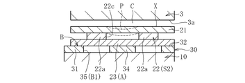
一方、各トップフォイル部21の下流側領域、特に、第一バックフォイル部22及び第二バックフォイル部23と軸方向で重ねられた重合部N(図11のV-V線、W-W線付近)では、図12(B)、(C)に示すように、第一バックフォイル部22とベースフォイル30との間に、規制部Aとしての第二バックフォイル部23が介在している。このため、この領域では、軸2の回転に伴って軸受隙間Cにおける流体圧力が高められた場合でも、第一バックフォイル部22が、ベースフォイル30の穴35に嵌まり込まず、常にベース面B(ベースフォイル30の上面)よりもスラストカラー3側に配される。これにより、第一バックフォイル部22のうち、ベース面Bの凹部B1に嵌まり込んだ上流側領域S1と、ベース面Bよりも上方に配された下流側領域S2との間に、段差が生じる(図11参照)。特に、本実施形態では、第一バックフォイル部22の下流側領域S2とベースフォイル30との間に第二バックフォイル部23が介在しているため、第一バックフォイル部22の上流側領域S1と下流側領域S2との段差が大きくなる。
On the other hand, the overlapping region N (VV line, WW line in FIG. 11) that overlaps the downstream region of each top foil part 21, in particular, the first back foil part 22 and the second back foil part 23 in the axial direction. In the vicinity), as shown in FIGS. 12B and 12C, the second back foil portion 23 as the restricting portion A is interposed between the first back foil portion 22 and the base foil 30. For this reason, in this region, even when the fluid pressure in the bearing gap C is increased as the shaft 2 rotates, the first back foil portion 22 does not fit into the hole 35 of the base foil 30, and the base surface always remains. It is arranged on the thrust collar 3 side from B (the upper surface of the base foil 30). Thereby, a level | step difference exists between the upstream area | region S1 fitted in the recessed part B1 of the base surface B among the 1st back foil parts 22, and the downstream area | region S2 distribute | arranged upwards rather than the base surface B. Occurs (see FIG. 11). In particular, in the present embodiment, since the second back foil portion 23 is interposed between the downstream region S2 of the first back foil portion 22 and the base foil 30, the upstream region S1 of the first back foil portion 22 is present. And the downstream area S2 become larger.
このように、第一バックフォイル部22に段差が形成されることで、この第一バックフォイル部22で支持されるトップフォイル部21が、第一バックフォイル部22に倣って湾曲し、軸受面Xが、下流側に行くにつれてスラストカラー3に接近する。これにより、トップフォイル部21の軸受面Xとスラストカラー3の端面3aとの間の軸受隙間Cが、下流側へ行くにつれて狭くなった断面楔状となる。そして、軸受隙間Cを流れる空気が、楔状の軸受隙間Cの小隙間部(各トップフォイル部21の下流側端部付近)に押し込まれることにより、軸受隙間Cの空気膜の圧力が高められ、この圧力により軸2及びスラストカラー3がスラスト方向に非接触支持される。
Thus, by forming a step in the first back foil portion 22, the top foil portion 21 supported by the first back foil portion 22 is curved following the first back foil portion 22, and the bearing surface X approaches the thrust collar 3 as it goes downstream. As a result, the bearing gap C between the bearing surface X of the top foil portion 21 and the end surface 3a of the thrust collar 3 has a wedge-shaped cross section that becomes narrower toward the downstream side. The air flowing through the bearing gap C is pushed into the small gap portion of the wedge-shaped bearing gap C (near the downstream end of each top foil portion 21), thereby increasing the pressure of the air film in the bearing gap C. With this pressure, the shaft 2 and the thrust collar 3 are supported in a non-contact manner in the thrust direction.
また、本実施形態では、第一バックフォイル部22に、一対の側部22a及び連結部22bで囲まれた穴22cが形成されている。この場合、軸受隙間Cの空気の圧力が高められると、トップフォイル部21の下流側領域のうち、半径方向両端部付近は第一バックフォイル部22の一対の側部22aで支持され{図12(B)参照}、下流側端部付近は第一バックフォイル部22の連結部22bで支持される{図12(C)参照}。一方、トップフォイル部21の下流側領域の半径方向中間部(図示例では、半径方向中央部)は、背後に第一バックフォイル部22の穴22c(非接触部)が配されるため、第一バックフォイル部22で支持されない。従って、トップフォイル部21の下流側領域の半径方向中央部には、その周囲よりも下方(ベース面B側)に凹んだ凹部Pが形成される{図2の網掛領域、及び図12(B)の点線参照}。これにより、軸受隙間Cを流れる空気が、各トップフォイル部21の下流側領域において半径方向中央部の凹部Pに集められるため、軸受隙間Cの圧力がさらに高められる。
Moreover, in this embodiment, the hole 22c enclosed by a pair of side part 22a and the connection part 22b is formed in the 1st back foil part 22. As shown in FIG. In this case, when the air pressure in the bearing gap C is increased, the vicinity of both ends in the radial direction in the downstream region of the top foil portion 21 is supported by the pair of side portions 22a of the first back foil portion 22 {FIG. (See (B)}, the vicinity of the downstream end is supported by the connecting portion 22b of the first back foil portion 22 (see FIG. 12C). On the other hand, since the hole 22c (non-contact part) of the first back foil part 22 is arranged behind the radial direction intermediate part (radial direction center part in the illustrated example) of the downstream region of the top foil part 21, It is not supported by one back foil part 22. Therefore, a concave portion P is formed in the central portion in the radial direction of the downstream region of the top foil portion 21 so as to be recessed below the base (base surface B side) {shaded region in FIG. 2 and FIG. ) See dotted line}. Thereby, since the air flowing through the bearing gap C is collected in the concave portion P in the central portion in the radial direction in the downstream region of each top foil portion 21, the pressure in the bearing gap C is further increased.
特に、図示例では、トップフォイル部21のうち、凹部Pの下流側に隣接した領域が、第一バックフォイル部22の連結部22bで支持されているため、この領域に、凹部Pよりもスラストカラー3側に近接した堰Qが設けられる{図2及び図12(C)参照}。この堰Qにより、凹部Pに集められた空気が下流側に抜けにくくなるため、軸受隙間Cの圧力がさらに高められる。
In particular, in the illustrated example, the region adjacent to the downstream side of the concave portion P in the top foil portion 21 is supported by the connecting portion 22b of the first back foil portion 22. A weir Q close to the collar 3 side is provided {see FIG. 2 and FIG. 12 (C)}. This weir Q makes it difficult for the air collected in the recess P to escape downstream, so that the pressure in the bearing gap C is further increased.
尚、軸2の停止直前や起動直後の低速回転時には、各トップフォイル部21の軸受面Xとスラストカラー3の端面3aとが接触摺動するため、これらの何れか一方または双方に、DLC膜、チタンアルミナイトライド膜、二硫化タングステン膜、あるいは二硫化モリブデン膜等の低摩擦化被膜を形成してもよい。
Note that the bearing surface X of each top foil portion 21 and the end surface 3a of the thrust collar 3 slide in contact with each other at the time of low-speed rotation immediately before the shaft 2 is stopped or immediately after the shaft 2 is driven. Alternatively, a low friction coating such as a titanium aluminum nitride film, a tungsten disulfide film, or a molybdenum disulfide film may be formed.
また、軸2の回転中は、トップフォイル部21、第一バックフォイル部22、第二バックフォイル部23、ベースフォイル30、及びフォイルホルダ10の端面10aの相互間で、微小摺動が生じる。この微小摺動による摩擦エネルギーにより、軸2の振動を減衰させることができる。このような微小摺動による摩擦力を調整するために、互いに摺動する面の何れか一方又は双方に、上記のような低摩擦化被膜を形成してもよい。
Further, during the rotation of the shaft 2, micro sliding occurs between the top foil part 21, the first back foil part 22, the second back foil part 23, the base foil 30, and the end surface 10 a of the foil holder 10. The vibration of the shaft 2 can be attenuated by the frictional energy generated by the minute sliding. In order to adjust the frictional force due to such micro-sliding, a low friction coating as described above may be formed on one or both of the surfaces that slide with each other.
本発明は、上記の実施形態に限られない。以下、本発明の他の実施形態を説明するが、上記の実施形態と重複する点については説明を省略する。
The present invention is not limited to the above embodiment. Hereinafter, although other embodiment of this invention is described, description is abbreviate | omitted about the point which overlaps with said embodiment.
図13に示す実施形態では、フォイル部材20が、第二バックフォイル部を有さず、トップフォイル部21及び第一バックフォイル部22のみで構成される。図示例では、第一バックフォイル部22が、穴を有さない略扇形に形成される。この実施形態のベースフォイル30は、例えば図14に示すように、半径方向に離隔した複数箇所に、大径環状部31、小径環状部32、及び半径方向部33で囲まれた穴35を有する。
In the embodiment shown in FIG. 13, the foil member 20 does not have the second back foil part, and is constituted only by the top foil part 21 and the first back foil part 22. In the example of illustration, the 1st back foil part 22 is formed in the substantially sector shape which does not have a hole. For example, as shown in FIG. 14, the base foil 30 of this embodiment has holes 35 surrounded by a large-diameter annular portion 31, a small-diameter annular portion 32, and a radial direction portion 33 at a plurality of locations separated in the radial direction. .
図14のベースフォイル30をフォイルホルダ10の端面10aに固定し、さらにその上に複数のフォイル部材20を固定する。このとき、各フォイル部材20のトップフォイル部21の背後に、上流側に隣接するフォイル部材20の第一バックフォイル部22が配される。各フォイル部材20の第一バックフォイル部22の上流側領域S1の背後に、ベースフォイル30の穴35が配される。各フォイル部材20の第一バックフォイル部22の下流側領域S2の背後に、ベースフォイル30の半径方向部33が配される。
14 is fixed to the end face 10a of the foil holder 10, and a plurality of foil members 20 are fixed thereon. At this time, the first back foil portion 22 of the foil member 20 adjacent to the upstream side is disposed behind the top foil portion 21 of each foil member 20. A hole 35 of the base foil 30 is disposed behind the upstream region S1 of the first back foil portion 22 of each foil member 20. A radial direction portion 33 of the base foil 30 is disposed behind the downstream region S2 of the first back foil portion 22 of each foil member 20.
軸2が回転して軸受隙間Cの流体圧力が高まると、図15に示すように、トップフォイル部21及び第一バックフォイル部22が下方(フォイルホルダ10側)に押し下げられる。このとき、第一バックフォイル部22の上流側領域S1が、ベース面Bの凹部B1(ベースフォイル30の穴35)に嵌まり込み、この領域で支持されたトップフォイル部21の上流側領域がベース面B側に押し込まれる{図16(A)参照}。一方、第一バックフォイル部22の下流側領域S2は、ベースフォイル30の半径方向部33で背後から支持されるため、ベース面Bの凹部B1に嵌まり込まない。すなわち、ベースフォイル30の半径方向部33が、第一バックフォイル部22の下流側領域S2の凹部B1への嵌まり込みを規制する規制部Aとして機能する。これにより、第一バックフォイル部22の下流側領域S2で支持されたトップフォイル部21の下流側領域は、ベース面Bよりも上方(スラストカラー3側)に配される{図16(B)参照}。以上により、トップフォイル部21が湾曲して、軸受面Xが下流側に行くにつれてスラストカラー3の端面3aに近接し、楔状の軸受隙間Cが形成される(図15参照)。
When the shaft 2 rotates and the fluid pressure in the bearing gap C increases, the top foil part 21 and the first back foil part 22 are pushed downward (foil holder 10 side) as shown in FIG. At this time, the upstream region S1 of the first back foil portion 22 is fitted into the recess B1 of the base surface B (the hole 35 of the base foil 30), and the upstream region of the top foil portion 21 supported in this region is It is pushed into the base surface B side {see FIG. 16 (A)}. On the other hand, the downstream region S2 of the first back foil portion 22 is supported from behind by the radial portion 33 of the base foil 30 and therefore does not fit into the recess B1 of the base surface B. That is, the radial direction portion 33 of the base foil 30 functions as a restricting portion A that restricts the fitting of the downstream region S2 of the first back foil portion 22 into the recess B1. Thereby, the downstream region of the top foil portion 21 supported by the downstream region S2 of the first back foil portion 22 is arranged above the base surface B (the thrust collar 3 side) {FIG. 16B reference}. As described above, the top foil portion 21 is curved, and the bearing surface X becomes closer to the end surface 3a of the thrust collar 3 as it goes downstream, so that a wedge-shaped bearing gap C is formed (see FIG. 15).
以上の実施形態では、フォイルホルダ10の端面10aとベースフォイル30とでベース面Bが形成され、ベースフォイル30の穴35で凹部B1が形成されているが、これに限られない。例えば、ベース面Bをフォイルホルダ10の端面10aのみで形成し、この端面10aに凹部B1を直接形成してもよい(図示省略)。
In the above embodiment, the base surface B is formed by the end surface 10a of the foil holder 10 and the base foil 30, and the recess B1 is formed by the hole 35 of the base foil 30, but it is not limited thereto. For example, the base surface B may be formed only by the end surface 10a of the foil holder 10, and the recess B1 may be directly formed on the end surface 10a (not shown).
また、以上の実施形態では、トップフォイル部21、第一バックフォイル部22、及び第二バックフォイル部23がフォイル部材20として一体に形成されているが、これらを別体に形成してもよい。この場合、複数のトップフォイル部21を連結して一体化したトップフォイル部材を設けてもよい。同様に、複数の第一バックフォイル部22を連結して一体化した第一バックフォイル部材や、複数の第二バックフォイル部23を連結して一体化した第二バックフォイル部材を設けてもよい。
Moreover, in the above embodiment, although the top foil part 21, the 1st back foil part 22, and the 2nd back foil part 23 are integrally formed as the foil member 20, you may form these separately. . In this case, you may provide the top foil member which connected and integrated the several top foil part 21. FIG. Similarly, a first back foil member in which a plurality of first back foil portions 22 are connected and integrated, or a second back foil member in which a plurality of second back foil portions 23 are connected and integrated may be provided. .
また、以上の実施形態では、本発明をスラストフォイル軸受に適用した場合を示したが、本発明を、軸をラジアル方向に支持するラジアルフォイル軸受に適用してもよい。例えば、図17に示すラジアルフォイル軸受40は、円筒状のフォイルホルダ41と、フォイルホルダ41の内周面41aに周方向に並べて取り付けられた複数のフォイル部材42とを有する。各フォイル部材42のうち、下流側の領域がトップフォイル部42aとして機能し、上流側の領域が第一バックフォイル部42b(散点模様で示す)として機能する。フォイルホルダ41の内周面41aはベース面Bとして機能し、この内周面41aに複数の凹部B1が設けられる。
In the above embodiment, the case where the present invention is applied to a thrust foil bearing has been described. However, the present invention may be applied to a radial foil bearing that supports a shaft in a radial direction. For example, the radial foil bearing 40 shown in FIG. 17 includes a cylindrical foil holder 41 and a plurality of foil members 42 attached to the inner peripheral surface 41a of the foil holder 41 side by side in the circumferential direction. Of each foil member 42, the downstream region functions as the top foil portion 42 a, and the upstream region functions as the first back foil portion 42 b (shown with a dotted pattern). The inner peripheral surface 41a of the foil holder 41 functions as a base surface B, and a plurality of recesses B1 are provided on the inner peripheral surface 41a.
軸2の回転に伴って、トップフォイル部42aの軸受面Xと軸2の外周面との間の軸受隙間Cの流体圧力が高められると、第一バックフォイル部42bの上流側領域がフォイルホルダ41の内周面41a(ベース面B)の凹部B1に嵌まり込む。一方、第一バックフォイル部42bの下流側領域は、フォイルホルダ41の内周面41aに背後から支持され、フォイルホルダ41の凹部B1に嵌まり込まない。すなわち、フォイルホルダ41の内周面41aのうち、凹部B1の下流側に隣接する領域が、第一バックフォイル部42bの下流側領域の凹部B1への嵌まり込みを規制する規制部Aとして機能する。これにより、第一バックフォイル部42bに段差が形成され、この第一バックフォイル部42bに倣ってトップフォイル部42aが湾曲し、軸受面Xが下流側に行くにつれて軸2の外周面に近接することで、楔状の軸受隙間Cが形成される。
When the fluid pressure in the bearing gap C between the bearing surface X of the top foil portion 42a and the outer peripheral surface of the shaft 2 is increased as the shaft 2 rotates, the upstream region of the first back foil portion 42b becomes a foil holder. The inner peripheral surface 41a (base surface B) 41 is fitted into the recess B1. On the other hand, the downstream region of the first back foil portion 42 b is supported from behind by the inner peripheral surface 41 a of the foil holder 41 and does not fit into the recess B 1 of the foil holder 41. That is, in the inner peripheral surface 41a of the foil holder 41, a region adjacent to the downstream side of the concave portion B1 functions as a regulating portion A that regulates the fitting of the first back foil portion 42b into the concave portion B1 in the downstream region. To do. Thereby, a step is formed in the first back foil portion 42b, the top foil portion 42a is curved following the first back foil portion 42b, and the bearing surface X becomes closer to the outer peripheral surface of the shaft 2 as it goes downstream. Thus, a wedge-shaped bearing gap C is formed.
以上の実施形態では、フォイル軸受を固定し、軸2を回転させた場合を示したが、これに限らず、軸2を固定し、フォイル軸受を回転させてもよい。ただし、フォイル軸受を回転させると、遠心力でフォイルが破損するおそれがあるため、上記の実施形態のようにフォイル軸受を固定することが好ましい。
In the above embodiment, the case where the foil bearing is fixed and the shaft 2 is rotated is shown. However, the present invention is not limited thereto, and the shaft 2 may be fixed and the foil bearing may be rotated. However, if the foil bearing is rotated, the foil may be damaged by centrifugal force. Therefore, it is preferable to fix the foil bearing as in the above embodiment.
また、以上に示したフォイル軸受は、例えばガスタービンやターボチャージャ(過給機)等のターボ機械の主軸用軸受、自動車等の車両用軸受、あるいは産業機器用の軸受等として使用することが可能である。
In addition, the foil bearings described above can be used, for example, as bearings for main shafts of turbo machines such as gas turbines and turbochargers (superchargers), bearings for vehicles such as automobiles, or bearings for industrial equipment. It is.
また、以上に述べたフォイル軸受は、圧力発生流体として空気を使用した空気動圧軸受のみならず、圧力発生流体として潤滑油を使用した油動圧軸受としても使用することができる。
Further, the foil bearing described above can be used not only as an air dynamic pressure bearing using air as a pressure generating fluid but also as an oil dynamic pressure bearing using lubricating oil as a pressure generating fluid.
1 フォイル軸受
2 軸
3 スラストカラー
10 フォイルホルダ
20 フォイル部材
21 トップフォイル部
22 第一バックフォイル部
22a 側部
22b 連結部
22c 穴(非接触部)
23 第二バックフォイル部
24 接続部
30 ベースフォイル
35 穴
A 規制部
B ベース面
B1 ベース面の凹部
C 軸受隙間
S1 第一バックフォイル部の上流側領域
S2 第一バックフォイル部の下流側領域
X 軸受面
P トップフォイル部の凹部
Q 堰 DESCRIPTION OFSYMBOLS 1 Foil bearing 2 Shaft 3 Thrust collar 10 Foil holder 20 Foil member 21 Top foil part 22 First back foil part 22a Side part 22b Connection part 22c Hole (non-contact part)
23 Secondback foil portion 24 Connection portion 30 Base foil 35 Hole A Restriction portion B Base surface B1 Recess C of the base surface C Bearing gap S1 Upstream region S2 of the first back foil portion Downstream region X of the first back foil portion Surface P Recess Q in top foil part Weir
2 軸
3 スラストカラー
10 フォイルホルダ
20 フォイル部材
21 トップフォイル部
22 第一バックフォイル部
22a 側部
22b 連結部
22c 穴(非接触部)
23 第二バックフォイル部
24 接続部
30 ベースフォイル
35 穴
A 規制部
B ベース面
B1 ベース面の凹部
C 軸受隙間
S1 第一バックフォイル部の上流側領域
S2 第一バックフォイル部の下流側領域
X 軸受面
P トップフォイル部の凹部
Q 堰 DESCRIPTION OF
23 Second
Claims (6)
- 軸受面を有するトップフォイル部と、前記トップフォイル部を背後から支持する第一バックフォイル部と、前記第一バックフォイル部を背後から支持するベース面とを備え、相対回転する軸と前記軸受面との間の軸受隙間に生じる流体圧力で、前記軸を非接触支持するフォイル軸受において、
前記ベース面に凹部を設け、
前記第一バックフォイル部の上流側領域を前記ベース面の凹部に嵌まり込み可能とし、 前記第一バックフォイル部の下流側領域の前記凹部への嵌まり込みを規制する規制部を有するフォイル軸受。 A shaft and a bearing surface having a top foil portion having a bearing surface, a first back foil portion for supporting the top foil portion from the back, and a base surface for supporting the first back foil portion from the back, and the bearing surface In the foil bearing that supports the shaft in a non-contact manner with the fluid pressure generated in the bearing gap between
A recess is provided in the base surface,
A foil bearing having a restricting portion that allows the upstream region of the first back foil portion to be fitted into the concave portion of the base surface and restricts the fitting of the downstream region of the first back foil portion into the concave portion. . - 前記ベース面と前記第一バックフォイル部の下流側領域との間に、前記規制部として機能する第二バックフォイル部を配した請求項1に記載のフォイル軸受。 The foil bearing according to claim 1, wherein a second back foil portion functioning as the restricting portion is disposed between the base surface and a downstream region of the first back foil portion.
- 前記トップフォイル部、前記第一バックフォイル部、及び前記第二バックフォイル部を一体に有するフォイル部材を備えた請求項2に記載のフォイル軸受。 The foil bearing according to claim 2, comprising a foil member integrally including the top foil portion, the first back foil portion, and the second back foil portion.
- 前記第一バックフォイル部のうち、軸の相対回転方向と直交する方向の中間部に、前記トップフォイル部と接触しない非接触部を設けた請求項1~3の何れか1項に記載のフォイル軸受。 The foil according to any one of claims 1 to 3, wherein a non-contact portion that does not contact the top foil portion is provided in an intermediate portion of the first back foil portion in a direction orthogonal to the relative rotation direction of the shaft. bearing.
- 前記第一バックフォイル部が、軸の相対回転方向と直交する方向に離隔した一対の側部と、前記一対の側部の下流側端部同士を連結する連結部とを有し、前記一対の側部と前記連結部とで囲まれた領域に、前記非接触部としての穴が形成された請求項4に記載のフォイル軸受。 The first back foil portion has a pair of side portions separated in a direction orthogonal to the relative rotation direction of the shaft, and a connecting portion that connects downstream end portions of the pair of side portions, The foil bearing according to claim 4, wherein a hole as the non-contact portion is formed in a region surrounded by a side portion and the connecting portion.
- 前記ベース面が、フォイルホルダと、前記フォイルホルダに取り付けられたベースフォイルとで形成され、
前記凹部が、前記ベースフォイルに設けられた穴で形成された請求項1~5の何れか1項に記載のフォイル軸受。 The base surface is formed of a foil holder and a base foil attached to the foil holder;
The foil bearing according to any one of claims 1 to 5, wherein the recess is formed by a hole provided in the base foil.
Applications Claiming Priority (2)
| Application Number | Priority Date | Filing Date | Title |
|---|---|---|---|
| JP2016142345A JP6800637B2 (en) | 2016-07-20 | 2016-07-20 | Foil bearing |
| JP2016-142345 | 2016-07-20 |
Publications (1)
| Publication Number | Publication Date |
|---|---|
| WO2018016268A1 true WO2018016268A1 (en) | 2018-01-25 |
Family
ID=60992127
Family Applications (1)
| Application Number | Title | Priority Date | Filing Date |
|---|---|---|---|
| PCT/JP2017/023304 WO2018016268A1 (en) | 2016-07-20 | 2017-06-23 | Foil bearing |
Country Status (2)
| Country | Link |
|---|---|
| JP (1) | JP6800637B2 (en) |
| WO (1) | WO2018016268A1 (en) |
Cited By (2)
| Publication number | Priority date | Publication date | Assignee | Title |
|---|---|---|---|---|
| WO2020148028A1 (en) * | 2019-01-14 | 2020-07-23 | Robert Bosch Gmbh | Axial foil bearing for fuel cell systems |
| CN112912635A (en) * | 2018-09-04 | 2021-06-04 | 株式会社Ihi | Thrust foil bearing |
Families Citing this family (2)
| Publication number | Priority date | Publication date | Assignee | Title |
|---|---|---|---|---|
| JP7048454B2 (en) * | 2018-08-30 | 2022-04-05 | Ntn株式会社 | Thrust foil bearing |
| CN111623043B (en) * | 2020-06-05 | 2021-12-24 | 重庆江增船舶重工有限公司 | Sliding bearing combined assembly method for exhaust gas turbocharger rotor |
Citations (4)
| Publication number | Priority date | Publication date | Assignee | Title |
|---|---|---|---|---|
| DE3442155A1 (en) * | 1984-11-17 | 1986-05-28 | SKF GmbH, 8720 Schweinfurt | Hydrodynamic foil bearing |
| JP2001519017A (en) * | 1997-04-03 | 2001-10-16 | サムソング・エアロスペース・インダストリーズ・リミテッド | Gas dynamic foil bearing |
| JP2001295836A (en) * | 2000-04-10 | 2001-10-26 | Honda Motor Co Ltd | Foil type fluid bearing |
| JP2015113927A (en) * | 2013-12-12 | 2015-06-22 | Ntn株式会社 | Foil bearing, foil bearing unit having the same, and turbomachine |
-
2016
- 2016-07-20 JP JP2016142345A patent/JP6800637B2/en active Active
-
2017
- 2017-06-23 WO PCT/JP2017/023304 patent/WO2018016268A1/en active Application Filing
Patent Citations (4)
| Publication number | Priority date | Publication date | Assignee | Title |
|---|---|---|---|---|
| DE3442155A1 (en) * | 1984-11-17 | 1986-05-28 | SKF GmbH, 8720 Schweinfurt | Hydrodynamic foil bearing |
| JP2001519017A (en) * | 1997-04-03 | 2001-10-16 | サムソング・エアロスペース・インダストリーズ・リミテッド | Gas dynamic foil bearing |
| JP2001295836A (en) * | 2000-04-10 | 2001-10-26 | Honda Motor Co Ltd | Foil type fluid bearing |
| JP2015113927A (en) * | 2013-12-12 | 2015-06-22 | Ntn株式会社 | Foil bearing, foil bearing unit having the same, and turbomachine |
Cited By (3)
| Publication number | Priority date | Publication date | Assignee | Title |
|---|---|---|---|---|
| CN112912635A (en) * | 2018-09-04 | 2021-06-04 | 株式会社Ihi | Thrust foil bearing |
| US11408466B2 (en) | 2018-09-04 | 2022-08-09 | Ihi Corporation | Thrust foil bearing |
| WO2020148028A1 (en) * | 2019-01-14 | 2020-07-23 | Robert Bosch Gmbh | Axial foil bearing for fuel cell systems |
Also Published As
| Publication number | Publication date |
|---|---|
| JP6800637B2 (en) | 2020-12-16 |
| JP2018013162A (en) | 2018-01-25 |
Similar Documents
| Publication | Publication Date | Title |
|---|---|---|
| JP5060288B2 (en) | Multi-thick film layer bearing cartridge and housing | |
| WO2018016268A1 (en) | Foil bearing | |
| US10012109B2 (en) | Foil bearing, and foil bearing unit and turbo machine each having same | |
| CA2699711C (en) | Hydrodynamic axial bearing | |
| US20160208847A1 (en) | Quad foil journal air bearing | |
| JP6615573B2 (en) | Thrust foil bearing | |
| EP1985873B1 (en) | Hydronomic bearing | |
| JP6979332B2 (en) | Tilting pad bearing | |
| JP2017187166A (en) | Foil bearing | |
| JP6651397B2 (en) | Foil bearing | |
| JP4442461B2 (en) | Liquid lubricated foil type hydrodynamic bearing | |
| JP2015132333A (en) | foil bearing | |
| WO2012057012A1 (en) | Bearing method for rotating shaft and device | |
| JP2017180685A (en) | Foil bearing | |
| JP7114520B2 (en) | Thrust foil bearings, foil bearing units, turbomachinery and foils | |
| JP2019019914A (en) | Foil bearing | |
| WO2017169676A1 (en) | Foil bearing | |
| JP6654081B2 (en) | Foil bearing | |
| JP6541946B2 (en) | Foil bearing and foil provided thereto | |
| JP6440999B2 (en) | Foil bearing and foil provided on the same | |
| JP5968399B2 (en) | Rotating shaft bearing method and apparatus | |
| JP6798810B2 (en) | Foil bearing | |
| WO2016031465A1 (en) | Foil bearing and foil disposed in same | |
| JP2020041589A (en) | Foil bearing |
Legal Events
| Date | Code | Title | Description |
|---|---|---|---|
| 121 | Ep: the epo has been informed by wipo that ep was designated in this application |
Ref document number: 17830788 Country of ref document: EP Kind code of ref document: A1 |
|
| NENP | Non-entry into the national phase |
Ref country code: DE |
|
| 122 | Ep: pct application non-entry in european phase |
Ref document number: 17830788 Country of ref document: EP Kind code of ref document: A1 |