WO2018016211A1 - Dynamic vibration absorber - Google Patents
Dynamic vibration absorber Download PDFInfo
- Publication number
- WO2018016211A1 WO2018016211A1 PCT/JP2017/020874 JP2017020874W WO2018016211A1 WO 2018016211 A1 WO2018016211 A1 WO 2018016211A1 JP 2017020874 W JP2017020874 W JP 2017020874W WO 2018016211 A1 WO2018016211 A1 WO 2018016211A1
- Authority
- WO
- WIPO (PCT)
- Prior art keywords
- base member
- dynamic vibration
- vibration absorber
- torque
- input
- Prior art date
Links
Images


Classifications
-
- F—MECHANICAL ENGINEERING; LIGHTING; HEATING; WEAPONS; BLASTING
- F16—ENGINEERING ELEMENTS AND UNITS; GENERAL MEASURES FOR PRODUCING AND MAINTAINING EFFECTIVE FUNCTIONING OF MACHINES OR INSTALLATIONS; THERMAL INSULATION IN GENERAL
- F16D—COUPLINGS FOR TRANSMITTING ROTATION; CLUTCHES; BRAKES
- F16D3/00—Yielding couplings, i.e. with means permitting movement between the connected parts during the drive
- F16D3/02—Yielding couplings, i.e. with means permitting movement between the connected parts during the drive adapted to specific functions
- F16D3/12—Yielding couplings, i.e. with means permitting movement between the connected parts during the drive adapted to specific functions specially adapted for accumulation of energy to absorb shocks or vibration
-
- F—MECHANICAL ENGINEERING; LIGHTING; HEATING; WEAPONS; BLASTING
- F16—ENGINEERING ELEMENTS AND UNITS; GENERAL MEASURES FOR PRODUCING AND MAINTAINING EFFECTIVE FUNCTIONING OF MACHINES OR INSTALLATIONS; THERMAL INSULATION IN GENERAL
- F16D—COUPLINGS FOR TRANSMITTING ROTATION; CLUTCHES; BRAKES
- F16D43/00—Automatic clutches
- F16D43/02—Automatic clutches actuated entirely mechanically
- F16D43/04—Automatic clutches actuated entirely mechanically controlled by angular speed
- F16D43/14—Automatic clutches actuated entirely mechanically controlled by angular speed with centrifugal masses actuating the clutching members directly in a direction which has at least a radial component; with centrifugal masses themselves being the clutching members
- F16D43/16—Automatic clutches actuated entirely mechanically controlled by angular speed with centrifugal masses actuating the clutching members directly in a direction which has at least a radial component; with centrifugal masses themselves being the clutching members with clutching members having interengaging parts
-
- F—MECHANICAL ENGINEERING; LIGHTING; HEATING; WEAPONS; BLASTING
- F16—ENGINEERING ELEMENTS AND UNITS; GENERAL MEASURES FOR PRODUCING AND MAINTAINING EFFECTIVE FUNCTIONING OF MACHINES OR INSTALLATIONS; THERMAL INSULATION IN GENERAL
- F16D—COUPLINGS FOR TRANSMITTING ROTATION; CLUTCHES; BRAKES
- F16D43/00—Automatic clutches
- F16D43/02—Automatic clutches actuated entirely mechanically
- F16D43/20—Automatic clutches actuated entirely mechanically controlled by torque, e.g. overload-release clutches, slip-clutches with means by which torque varies the clutching pressure
- F16D43/202—Automatic clutches actuated entirely mechanically controlled by torque, e.g. overload-release clutches, slip-clutches with means by which torque varies the clutching pressure of the ratchet type
- F16D43/204—Automatic clutches actuated entirely mechanically controlled by torque, e.g. overload-release clutches, slip-clutches with means by which torque varies the clutching pressure of the ratchet type with intermediate balls or rollers
- F16D43/208—Automatic clutches actuated entirely mechanically controlled by torque, e.g. overload-release clutches, slip-clutches with means by which torque varies the clutching pressure of the ratchet type with intermediate balls or rollers moving radially between engagement and disengagement
-
- F—MECHANICAL ENGINEERING; LIGHTING; HEATING; WEAPONS; BLASTING
- F16—ENGINEERING ELEMENTS AND UNITS; GENERAL MEASURES FOR PRODUCING AND MAINTAINING EFFECTIVE FUNCTIONING OF MACHINES OR INSTALLATIONS; THERMAL INSULATION IN GENERAL
- F16D—COUPLINGS FOR TRANSMITTING ROTATION; CLUTCHES; BRAKES
- F16D7/00—Slip couplings, e.g. slipping on overload, for absorbing shock
- F16D7/04—Slip couplings, e.g. slipping on overload, for absorbing shock of the ratchet type
- F16D7/06—Slip couplings, e.g. slipping on overload, for absorbing shock of the ratchet type with intermediate balls or rollers
-
- F—MECHANICAL ENGINEERING; LIGHTING; HEATING; WEAPONS; BLASTING
- F16—ENGINEERING ELEMENTS AND UNITS; GENERAL MEASURES FOR PRODUCING AND MAINTAINING EFFECTIVE FUNCTIONING OF MACHINES OR INSTALLATIONS; THERMAL INSULATION IN GENERAL
- F16F—SPRINGS; SHOCK-ABSORBERS; MEANS FOR DAMPING VIBRATION
- F16F15/00—Suppression of vibrations in systems; Means or arrangements for avoiding or reducing out-of-balance forces, e.g. due to motion
- F16F15/10—Suppression of vibrations in rotating systems by making use of members moving with the system
- F16F15/12—Suppression of vibrations in rotating systems by making use of members moving with the system using elastic members or friction-damping members, e.g. between a rotating shaft and a gyratory mass mounted thereon
- F16F15/131—Suppression of vibrations in rotating systems by making use of members moving with the system using elastic members or friction-damping members, e.g. between a rotating shaft and a gyratory mass mounted thereon the rotating system comprising two or more gyratory masses
- F16F15/139—Suppression of vibrations in rotating systems by making use of members moving with the system using elastic members or friction-damping members, e.g. between a rotating shaft and a gyratory mass mounted thereon the rotating system comprising two or more gyratory masses characterised by friction-damping means
- F16F15/1397—Overload protection, i.e. means for limiting torque
-
- F—MECHANICAL ENGINEERING; LIGHTING; HEATING; WEAPONS; BLASTING
- F16—ENGINEERING ELEMENTS AND UNITS; GENERAL MEASURES FOR PRODUCING AND MAINTAINING EFFECTIVE FUNCTIONING OF MACHINES OR INSTALLATIONS; THERMAL INSULATION IN GENERAL
- F16F—SPRINGS; SHOCK-ABSORBERS; MEANS FOR DAMPING VIBRATION
- F16F15/00—Suppression of vibrations in systems; Means or arrangements for avoiding or reducing out-of-balance forces, e.g. due to motion
- F16F15/10—Suppression of vibrations in rotating systems by making use of members moving with the system
- F16F15/14—Suppression of vibrations in rotating systems by making use of members moving with the system using masses freely rotating with the system, i.e. uninvolved in transmitting driveline torque, e.g. rotative dynamic dampers
- F16F15/1407—Suppression of vibrations in rotating systems by making use of members moving with the system using masses freely rotating with the system, i.e. uninvolved in transmitting driveline torque, e.g. rotative dynamic dampers the rotation being limited with respect to the driving means
- F16F15/145—Masses mounted with play with respect to driving means thus enabling free movement over a limited range
-
- F—MECHANICAL ENGINEERING; LIGHTING; HEATING; WEAPONS; BLASTING
- F16—ENGINEERING ELEMENTS AND UNITS; GENERAL MEASURES FOR PRODUCING AND MAINTAINING EFFECTIVE FUNCTIONING OF MACHINES OR INSTALLATIONS; THERMAL INSULATION IN GENERAL
- F16F—SPRINGS; SHOCK-ABSORBERS; MEANS FOR DAMPING VIBRATION
- F16F15/00—Suppression of vibrations in systems; Means or arrangements for avoiding or reducing out-of-balance forces, e.g. due to motion
- F16F15/10—Suppression of vibrations in rotating systems by making use of members moving with the system
- F16F15/16—Suppression of vibrations in rotating systems by making use of members moving with the system using a fluid or pasty material
- F16F15/167—Suppression of vibrations in rotating systems by making use of members moving with the system using a fluid or pasty material having an inertia member, e.g. ring
- F16F15/173—Suppression of vibrations in rotating systems by making use of members moving with the system using a fluid or pasty material having an inertia member, e.g. ring provided within a closed housing
Definitions
- the present invention relates to a dynamic vibration absorber.
- a damper device or the like is installed between an automobile engine and a transmission.
- the damper device includes an input member that receives torque from the engine, an output member that outputs torque input to the input member to the transmission, and an elastic member that elastically connects the input member and the output member. I have. By installing this damper device in the torque transmission path between the engine and the transmission, the rotational speed fluctuation from the engine is suppressed.
- a dynamic vibration absorber may be attached to a rotating member such as the above-described damper device in order to more appropriately suppress rotational speed fluctuations.
- the excessive torque may be transmitted to the dynamic vibration absorber, and the rotating member may be damaged by the inertial force of the dynamic vibration absorber. is there.
- An object of the present invention is to provide a dynamic vibration absorber that can prevent damage to a rotating member even when excessive torque is input to the rotating member.
- the dynamic vibration absorber is configured to be attached to a rotating member.
- the dynamic vibration absorber includes a base member, a mass body, and a torque limiting unit.
- the base member is rotatably arranged.
- the mass body is attached so as to be rotatable relative to the base member.
- the torque limiting unit limits transmission of torque input from the rotating member to the base member.
- the torque limiting unit is configured to rotate the base member integrally with the rotating member when the torque input to the base member is less than a threshold value.
- the torque limiting unit is configured to rotate the base unit relative to the rotating member when the torque input to the base member is equal to or greater than a threshold value.
- the torque limiting portion includes a biasing member that biases the base member toward the rotating member.
- the dynamic vibration absorber further includes a housing and a viscous fluid.
- the housing is attached to the base member and accommodates the mass body.
- the viscous fluid is filled in the housing.
- the mass body may swing in the circumferential direction with respect to the base member.
- the oscillation center of the mass body may be arranged at a position different from the rotation center of the base member.
- the dynamic vibration absorber may further include a centrifuge and a cam mechanism.
- the centrifuge is arranged to receive a centrifugal force due to the rotation of the base member.
- the cam mechanism converts a centrifugal force acting on the centrifuge into a circumferential force.
- the dynamic vibration absorber can be prevented from damaging the rotating member.
- the axial direction means a direction in which the rotation axis O of the damper device 100 extends.
- the radial direction means a radial direction of a circle around the rotation axis O.
- the circumferential direction means a circumferential direction of a circle around the rotation axis O.
- the damper device 100 includes a damper device body 2 (an example of a rotating member) and a dynamic vibration absorber 3.
- the damper device 100 is configured to transmit torque from the engine and attenuate rotational speed fluctuations.
- the damper device 100 is disposed so as to be rotatable about the rotation axis O.
- the damper device 100 is a dry type damper device 100. That is, the damper device 100 is disposed in a dry environment that is not filled with a viscous fluid. And the input member 21 and the output member 22 mentioned later rotate in a dry environment.
- the damper device body 2 includes an input member 21 and an output member 22.
- the input member 21 is a flywheel to which torque from an engine is input, for example.
- the input member 21 is fixed to the crankshaft of the engine.
- the input member 21 has a disk shape.
- the input member 21 has an accommodation space 21a.
- the accommodation space 21a extends in the circumferential direction.
- An elastic member 23 to be described later is accommodated in the accommodation space 21a.
- the accommodating space 21a may be filled with a viscous fluid.
- grease may be filled in the accommodation space 21a.
- the input member 21 has an input plate 21b and an accommodation plate 21c.
- An accommodation space 21a is formed by the input plate 21b and the accommodation plate 21c.
- the input member 21 has a ring gear 21d.
- the ring gear 21d is fixed to the input plate 21b.
- the output member 22 outputs the torque input to the input member 21.
- the output member 22 is connected to the input member 21 so as to be relatively rotatable.
- the damper device main body 2 has a plurality of elastic members 23.
- the elastic member 23 is, for example, a coil spring. The elastic member 23 elastically connects the input member 21 and the output member 22.
- the dynamic vibration absorber 3 is attached to the damper device main body 2. Specifically, the dynamic vibration absorber 3 is attached to the input member 21 of the damper device main body 2. The dynamic vibration absorber 3 is arranged side by side with the damper device main body 2 in the axial direction. That is, the dynamic vibration absorber 3 is disposed so as to overlap the damper device main body 2 when viewed in the axial direction.
- the dynamic vibration absorber 3 is configured to attenuate the vibration of the damper device body 2. As shown in FIG. 2, the dynamic vibration absorber 3 includes mass bodies 31 a and 31 b, a housing 32, a viscous fluid 33, a base member 34, and a torque limiting unit 50.
- the dynamic vibration absorber 3 includes a first lid member 35a, a second lid member 35b, and a plurality of coil springs 36.
- the mass body is composed of a first mass body 31a and a second mass body 31b.
- the base member 34 is disposed so as to be rotatable about the rotation axis O.
- the base member 34 is attached to the damper device main body 2 via the torque limiting unit 50.
- the base member 34 is attached to the input member 21 of the damper device main body 2 via the torque limiting unit 50.
- the base member 34 rotates integrally with the damper device main body 2 when the torque input from the damper device main body 2 is less than a predetermined threshold.
- the base member 34 rotates integrally with the input member 21 of the damper device main body 2 when the torque input from the input member 21 of the damper device main body 2 is less than a predetermined threshold.
- the base member 34 is annular. An inner peripheral end portion of the base member 34 is attached to the damper device main body 2 via a torque limiting portion 50.
- the base member 34 has a plurality of accommodating portions 341.
- Each accommodating part 341 is arrange
- Each accommodating portion 341 extends in the circumferential direction.
- a long hole 342 is formed between the adjacent accommodating portions 341. The long hole 342 extends in the circumferential direction and is disposed on the same circumference as the housing portion 341.
- the torque limiting unit 50 limits the transmission of torque input from the input member 21 of the damper device body 2 to the base member 34. Specifically, the torque limiting unit 50 rotates the base member 34 integrally with the input member 21 when the torque input to the base member 34 is less than a predetermined threshold value. That is, the torque limiting unit 50 transmits the torque from the input member 21 to the base member 34. On the other hand, when the torque input to the base member 34 is equal to or greater than a predetermined threshold, the torque limiting unit 50 rotates the base member 34 relative to the input member 21. That is, the torque limiting unit 50 does not transmit the torque from the input member 21 to the base member 34.
- the torque limiter 50 limits the transmission of torque input from the damper device body 2 to the base member 34 by the frictional force.
- the torque limiting unit 50 has a biasing member 51.
- the biasing member 51 biases the base member 34 toward the input member 21 in the axial direction.
- the biasing member 51 is in contact with the inner peripheral end of the base member 34.
- the base member 34 is sandwiched between the input member 21 and the biasing member 51.
- the base member 34 rotates integrally with the input member 21 by a static frictional force with the input member 21.
- a force exceeding the maximum static friction force is applied to the base member 34, and the base member 34 rotates relative to the input member 21.
- a friction material may be interposed between the base member 34 and the input member 21.
- the biasing member 51 is, for example, a disc spring.
- the outer peripheral end of the urging member 51 is in contact with the base member 34. Further, the inner peripheral end of the urging member 51 is in contact with a support plate 52 described later.
- the torque limiting unit 50 further includes a support plate 52.
- the support plate 52 supports the biasing member 51 in the axial direction.
- the support plate 52 is disposed at a distance from the base member 34 in the axial direction.
- the biasing member 51 is disposed between the base member 34 and the support plate 52 in the axial direction.
- the biasing member 51 has one end in contact with the base member 34 and the other end in contact with the support plate 52 in the axial direction.
- the urging member 51 is disposed between the base member 34 and the support plate 52 in a compressed state.
- the torque limiting unit 50 further has a spacer 53.
- the spacer 53 is cylindrical.
- the spacer 53 is disposed between the input member 21 and the support plate 52 in the axial direction.
- the rivet 101 fastens the input member 21, the support plate 52, and the spacer 53.
- the spacer 53 secures a space between the input member 21 and the support plate 52 in the axial direction.
- the base member 34 and the urging member 51 are disposed in the axial space secured by the spacer 53.
- the first and second mass bodies 31 a and 31 b can be rotated relative to the base member 34. Further, the first and second mass bodies 31 a and 31 b can rotate around the rotation axis O.
- the first and second mass bodies 31a and 31b are formed by pressing a sheet metal member.
- the first and second mass bodies 31 a and 31 b are disposed on both sides of the base member 34 in the axial direction. That is, the first mass body 31 a is disposed on the engine side of the base member 34, and the second mass body 31 b is disposed on the transmission side of the base member 34.
- the first and second mass bodies 31 a and 31 b have a plurality of accommodating portions 311.
- Each accommodating part 311 is arrange
- Each accommodating portion 311 is disposed at a position corresponding to each accommodating portion 341 of the base member 34.
- the first and second mass bodies 31 a and 31 b have a through hole 312 at a position corresponding to the center position in the circumferential direction of the long hole 342 of the base member 34.
- the first lid member 35a is annular and is disposed on the engine side of the first mass body 31a. That is, the first mass body 31 a is sandwiched between the first lid member 35 a and the base member 34. As shown in an enlarged view in FIG. 5, a through hole 351 is formed in the first lid member 35a at a position corresponding to the through hole 312 of the first mass body 31a.
- the second lid member 35b is disposed on the transmission side of the second mass body 31b. That is, the second mass body 31b is sandwiched between the second lid member 35b and the base member 34. As shown in an enlarged view in FIG. 5, the second lid member 35b is an annular member. A through hole 351 is formed in the second lid member 35b at a position corresponding to the through hole 312 of the second mass body 31b.
- the plurality of coil springs 36 are housed in the housing portion 341 of the base member 34 and the housing portions 311 of the first and second mass bodies 31a and 31b, respectively. Both end portions of the coil spring 36 are in contact with the circumferential end portions of the base member 34 and the accommodating portions 341 and 311 of the first and second mass bodies 31a and 31b.
- the stop pin 37 has a large-diameter trunk 371 at the center in the axial direction and small-diameter trunks 372 on both sides thereof.
- the large diameter body 371 is larger in diameter than the through holes 312 of the first and second mass bodies 31a and 31b, and smaller in diameter than the diameter (diameter dimension) of the long hole 342 of the base member 34. Further, the thickness of the large-diameter body portion 371 is slightly thicker than the thickness of the base member 34.
- the small diameter body 372 is inserted through the through holes 312 of the first and second mass bodies 31a and 31b and the through holes 351 of the lid members 35a and 35b.
- the first and second mass bodies 31a and 31b and the lid members 35a and 35b are fixed to both sides of the base member 34 in the axial direction by caulking the head of the small diameter body 372.
- the base member 34 has a range in which the stop pin 37 can move in the long hole 342 of the base member 34 with respect to the first and second mass bodies 31a and 31b and the two lid members 35a and 35b. Relative rotation is possible. Then, when the large-diameter body portion 371 of the stop pin 37 abuts against the end portion of the long hole 342, the relative rotation of both is restricted.
- the housing 32 is configured to accommodate the first and second mass bodies 31a and 31b.
- the housing 32 also houses a coil spring 36 and the like.
- the housing 32 is attached to the base member 34 by a fastening member 102 such as a rivet.
- the housing 32 is composed of two annular plates 321. Each annular plate 321 forms an internal space. That is, the annular plates 321 are arranged side by side in the axial direction. Each annular plate 321 swells in a direction away from each other to form an internal space.
- Each annular plate 321 has an outer peripheral flange 322 at the outer peripheral end.
- the annular plates 321 are fixed to each other at the outer peripheral flange 322 by a fastening member 103 such as a rivet. That is, the outer peripheral flanges 322 of the annular plates 321 are in contact with each other.
- the outer peripheral flanges 322 are fixed to each other by the fastening member 103 penetrating the outer peripheral flanges 322.
- the outer peripheral flanges 322 may be fixed to each other by welding or the like.
- Each annular plate 321 has an inner peripheral flange 323 at the inner peripheral end.
- Each inner peripheral flange 323 is in contact with the base member 34. That is, each inner peripheral flange 323 is disposed so as to sandwich the base member 34.
- Each inner peripheral flange 323 is fixed to the base member 34 by a fastening member 102 that passes through each inner peripheral flange 323 and the base member 34.
- Each inner peripheral flange 323 may be fixed to the base member 34 by welding or the like.
- the housing 32 is filled with a viscous fluid 33.
- a viscous fluid 33 for example, lubricating oil or the like can be used.
- the dynamic vibration absorber 3 is attached to the input member 21 of the damper apparatus main body 2, the structure of the damper apparatus 100 is not limited to this.
- the dynamic vibration absorber 3 may be attached to the output member 22 of the damper device main body 2.
- the base member 34 of the dynamic vibration absorber 3 is attached to the output member 22 via the torque limiting unit 50.
- the dynamic vibration absorber 3 can be attached to various places of the damper device main body 2 via the torque limiting portion 50.
- the damper device body 2 includes an input member 21, an output member 22, an elastic member 23, and a clutch portion 24.
- An elastic member 23 is provided between the input member 21 and the output member 22, and the input member 21 and the output member 22 are elastically connected.
- a clutch portion 24 is provided between the input member 21 and the elastic member 23.
- the dynamic vibration absorber 3 is attached to the output member 22.
- a clutch portion 24 is provided between the elastic member 23 and the output member 22.
- the dynamic vibration absorber 3 is attached to the output member 22.
- a clutch portion 24 is provided between the elastic member 23 and the output member 22.
- the dynamic vibration absorber 3 is attached between the elastic member 23 and the clutch portion 24.
- a clutch portion 24 is provided between the elastic member 23 and the output member 22.
- the dynamic vibration absorber 3 is attached to the input member 21.
- a clutch portion 24 is provided between the input member 21 and the elastic member 23.
- the dynamic vibration absorber 3 is attached to the input member 21.
- a clutch portion 24 is provided between the input member 21 and the elastic member 23.
- the dynamic vibration absorber 3 is attached between the clutch portion 24 and the elastic member 23.
- the torque limiting unit 50 restricts the transmission of torque to the base member 34, whereby the damper device main body. 2 damage can be effectively prevented.
- the torque limiting unit 50 restricts the torque from being transmitted to the base member 34, so that the damper device main body 2 Damage can be effectively prevented.
- the damper device body 2 may include an input member 21, an output member 22, first and second elastic members 23 a and 23 b, and an intermediate member 25.
- the dynamic vibration absorber 3 may be attached to the intermediate member 25.
- the first and second elastic members 23 a and 23 b elastically connect the input member 21 and the output member 22.
- the first elastic member 23a is an outer peripheral side torsion spring disposed on the outer peripheral side
- the second elastic member 23b is an inner peripheral side torsion spring disposed on the inner peripheral side.
- the intermediate member 25 connects the first elastic member 23a and the second elastic member 23b.
- the intermediate member 25 connects the first elastic member 23a and the second elastic member 23b in series.
- the dynamic vibration absorber 3 is attached to the intermediate member 25.
- the structure of the dynamic vibration absorber 3 is not limited to the structure of the said embodiment.
- the first and second mass bodies 31 a and 31 b of the dynamic vibration absorber 3 may be attached to the base member 34 so as to be swingable in the circumferential direction. And it can be set as the structure which attenuates a rotation fluctuation
- the swing center S of the first and second mass bodies 31 a and 31 b is disposed at a position different from the rotational axis O of the damper device 100.
- an arc-shaped slit 343 is formed in the base member 34.
- the slit 343 is formed in an arc shape having a radius R ⁇ b> 2 centered on a point S separated from the rotation axis O of the damper device 100 by a predetermined distance R ⁇ b> 1.
- the slit 343 extends in the rotation direction.
- a collar 38 is disposed in the slit 343.
- the collar 38 is cylindrical.
- the diameter of the collar 38 is smaller than the radial width of the slit 343.
- the length of the collar 38 is longer than that of the base member 34.
- the collar 38 is disposed between the first and second mass bodies 31a and 31b in the axial direction.
- the first mass body 31a, the second mass body 31b, and the collar 38 are fixed by the rivet 39.
- the first and second mass bodies 31 a and 31 b swing along the slit 343.
- the housing 32 is not shown for easy illustration.
- the structure of the dynamic vibration absorber 3 is not limited to the structure of the said embodiment.
- the dynamic vibration absorber 3 includes a mass body 31, a centrifuge 40, and a cam mechanism 41.
- the dynamic vibration absorber 3 may have a coil spring 42.
- the mass body 31 is, for example, annular, and is disposed on the outer side in the radial direction of the base member 34. In the radial direction, the mass body 31 and the base member 34 are arranged at an interval. Note that the mass body 31 and the base member 34 are arranged side by side in the radial direction. That is, the mass body 31 and the base member 34 overlap in the radial direction view.
- the mass body 31 and the base member 34 rotate around the rotation axis O.
- the mass body 31 and the base member 34 are relatively rotatable.
- the centrifuge 40 is disposed on the base member 34 and can be moved outward in the radial direction by the centrifugal force generated by the rotation of the base member 34. More specifically, as shown in an enlarged view in FIG. 17, the base member 34 is provided with a recess 344 on the outer peripheral surface.
- the concave portion 344 is formed in a rectangular shape on the outer peripheral surface of the base member 34 so as to be recessed toward the center of rotation on the inner peripheral side.
- the centrifuge 40 is inserted into the recess 344 so as to be movable in the radial direction.
- the centrifuge 40 and the recess 344 are set such that the friction coefficient between the side surface of the centrifuge 40 and the recess 344 is 0.1 or less.
- the centrifuge 40 is a plate having substantially the same thickness as the base member 34, and the outer peripheral surface 401 is formed in an arc shape. Further, a roller accommodating portion 402 that is recessed inward is formed on the outer peripheral surface 401 of the centrifuge 40.
- the cam mechanism 41 includes a roller 411 as a cam follower and a cam 412 formed on the inner peripheral surface of the mass body 31.
- the roller 411 is attached to the roller accommodating portion 402 of the centrifuge 40 and is movable in the radial direction together with the centrifuge 40.
- the roller 411 may be rotatable or fixed in the roller housing portion 402.
- the cam 412 is an arcuate surface with which the roller 411 contacts. When the base member 34 and the mass body 31 are relatively rotated within a predetermined angle range, the roller 411 moves along the cam 412.
- the coil spring 42 is disposed between the bottom surface of the recess 344 and the radially inner side surface of the centrifuge 40, and urges the centrifuge 40 radially outward.
- the centrifuge 40 and the roller 411 are pressed against the cam 412 of the mass body 31 by the urging force of the coil spring 42. Therefore, even when the centrifugal force is not acting on the centrifuge 40 with the base member 34 not rotating, the roller 411 contacts the cam 412.
- the torque transmitted to the damper device main body 2 is transmitted to the base member 34 when the value is less than a predetermined threshold value.
- the base member 34 and the mass body 31 rotate in the state shown in FIG. That is, the roller 411 of the cam mechanism 41 contacts the deepest position (circumferential center position) of the cam 412, and the rotational phase difference between the base member 34 and the mass body 31 is “0”.
- the relative displacement in the rotation direction between the base member 34 and the mass body 31 is referred to as a “rotation phase difference”, which is the centrifuge 40 and the roller 411 in FIGS. 17 and 18.
- the difference between the center position in the circumferential direction and the center position in the circumferential direction of the cam 412 is shown.
- FIG. 18A shows a case where a rotational phase difference + ⁇ is generated on the + R side
- FIG. 18B shows a case where a rotational phase difference ⁇ is generated on the ⁇ R side.
- the first component force P1 is a force that moves the base member 34 to the right in FIG. 18A via the cam mechanism 41. That is, a force in the direction of reducing the rotational phase difference between the base member 34 and the mass body 31 acts on the base member 34. Further, the centrifuge 40 and the roller 411 are moved to the radially inner peripheral side against the urging force of the coil spring 42 by the second component force P2.
- FIG. 18B shows a case where a rotational phase difference ⁇ is generated between the base member 34 and the mass body 31.
- the moving direction of the roller 411 of the cam mechanism 41, the reaction force P 0, and the first component force The operation is the same except that the directions of P1 and the second component force P2 are different from those in FIG.
- the force that suppresses the above torque fluctuation changes depending on the centrifugal force, that is, the rotational speed of the base member 34, and also changes depending on the rotational phase difference and the shape of the cam 412. Therefore, by appropriately setting the shape of the cam 412, the characteristics of the damper device 100 can be optimized according to the engine specifications and the like.
- the shape of the cam 412 can be made such that the first component force P1 changes linearly according to the rotational phase difference in the state where the same centrifugal force is acting.
- the shape of the cam 412 can be a shape in which the first component force P1 changes nonlinearly according to the rotational phase difference.
Abstract
A dynamic vibration absorber (3) is configured so as to be attached to a damper device body. The dynamic vibration absorber (3) is provided with a base member (34), objects of mass (31a, 31b), and a torque limiter (50). The base member (34) is arranged so as to be able to rotate. The objects of mass (31a, 31b) are attached to the base member (34) so as to be able to rotate relative thereto. The torque limiter (50) limits the transmission of torque inputted from the damper device body to the base member (34).
Description
本発明は、動吸振器に関するものである。
The present invention relates to a dynamic vibration absorber.
例えば、自動車のエンジンとトランスミッションとの間にダンパ装置などが設置されている。ダンパ装置は、エンジンからのトルクが入力される入力部材と、入力部材に入力されるトルクをトランスミッションへと出力する出力部材と、入力部材と出力部材とを弾性的に連結する弾性部材と、を備えている。エンジンとトランスミッションとのトルク伝達経路にこのダンパ装置を設置することによって、エンジンからの回転速度変動を抑制している。
For example, a damper device or the like is installed between an automobile engine and a transmission. The damper device includes an input member that receives torque from the engine, an output member that outputs torque input to the input member to the transmission, and an elastic member that elastically connects the input member and the output member. I have. By installing this damper device in the torque transmission path between the engine and the transmission, the rotational speed fluctuation from the engine is suppressed.
上述したダンパ装置のような回転部材に対して、より適切に回転速度変動を抑制するために動吸振器を取り付けることがある。しかし、急発進又は急ブレーキなどによって過大なトルクが回転部材に入力された場合、その過大なトルクが動吸振器に伝達し、動吸振器の慣性力によって回転部材などを損傷させてしまうおそれがある。
A dynamic vibration absorber may be attached to a rotating member such as the above-described damper device in order to more appropriately suppress rotational speed fluctuations. However, if excessive torque is input to the rotating member due to sudden start or braking, the excessive torque may be transmitted to the dynamic vibration absorber, and the rotating member may be damaged by the inertial force of the dynamic vibration absorber. is there.
本発明の課題は、過大なトルクが回転部材に入力された場合であっても、回転部材の損傷を防止できる動吸振器を提供することにある。
An object of the present invention is to provide a dynamic vibration absorber that can prevent damage to a rotating member even when excessive torque is input to the rotating member.
本発明のある側面に係る動吸振器は、回転部材に取り付けられるように構成されている。この動吸振器は、ベース部材と、質量体と、トルク制限部とを備えている。ベース部材は、回転可能に配置されている。質量体は、ベース部材に対して相対回転可能に取り付けられている。トルク制限部は、回転部材からベース部材に入力されるトルクの伝達を制限する。
The dynamic vibration absorber according to an aspect of the present invention is configured to be attached to a rotating member. The dynamic vibration absorber includes a base member, a mass body, and a torque limiting unit. The base member is rotatably arranged. The mass body is attached so as to be rotatable relative to the base member. The torque limiting unit limits transmission of torque input from the rotating member to the base member.
この構成によれば、トルク制限部によって、回転部材からベース部材に入力されるトルクの伝達を制限している。このため、過大なトルクが回転部材に入力された場合、トルク制限部は、そのトルクをベース部材に伝達しない。この結果、動吸振器が回転部材を損傷させることを防止することができる。
According to this configuration, transmission of torque input from the rotating member to the base member is limited by the torque limiting unit. For this reason, when an excessive torque is input to the rotating member, the torque limiting unit does not transmit the torque to the base member. As a result, the dynamic vibration absorber can be prevented from damaging the rotating member.
好ましくは、トルク制限部は、ベース部材に入力されるトルクが閾値未満の場合、ベース部材を回転部材と一体回転させるように構成されている。また、好ましくは、トルク制限部は、ベース部材に入力されるトルクが閾値以上の場合、ベース部を回転部材と相対回転させるように構成されている。
Preferably, the torque limiting unit is configured to rotate the base member integrally with the rotating member when the torque input to the base member is less than a threshold value. Preferably, the torque limiting unit is configured to rotate the base unit relative to the rotating member when the torque input to the base member is equal to or greater than a threshold value.
好ましくは、トルク制限部は、ベース部材を回転部材に向かって付勢する付勢部材を有する。
Preferably, the torque limiting portion includes a biasing member that biases the base member toward the rotating member.
好ましくは、動吸振器は、ハウジングと、粘性流体とをさらに備えている。ハウジングは、ベース部材に取り付けられ、質量体を収容する。粘性流体は、ハウジング内に充填されている。
Preferably, the dynamic vibration absorber further includes a housing and a viscous fluid. The housing is attached to the base member and accommodates the mass body. The viscous fluid is filled in the housing.
質量体は、ベース部材に対して周方向に揺動してもよい。この質量体の揺動中心は、ベース部材の回転中心と異なる位置に配置されてもよい。
The mass body may swing in the circumferential direction with respect to the base member. The oscillation center of the mass body may be arranged at a position different from the rotation center of the base member.
動吸振器は、遠心子と、カム機構とをさらに備えていてもよい。遠心子は、ベース部材の回転による遠心力を受けるように配置されている。カム機構は、遠心子に作用する遠心力を円周方向の力に変換する。
The dynamic vibration absorber may further include a centrifuge and a cam mechanism. The centrifuge is arranged to receive a centrifugal force due to the rotation of the base member. The cam mechanism converts a centrifugal force acting on the centrifuge into a circumferential force.
本発明によれば、過大なトルクが回転部材に入力された場合であっても、動吸振器が回転部材を損傷させることを防止できる。
According to the present invention, even if excessive torque is input to the rotating member, the dynamic vibration absorber can be prevented from damaging the rotating member.
以下、本発明に係る動吸振器を備えるダンパ装置の実施形態について図面を参照しつつ説明する。なお、以下の説明において、軸方向とは、ダンパ装置100の回転軸Oが延びる方向を意味する。また、径方向とは、回転軸Oを中心とした円の径方向を意味する。また、周方向とは、回転軸Oを中心とした円の周方向を意味する。
Hereinafter, embodiments of a damper device including a dynamic vibration absorber according to the present invention will be described with reference to the drawings. In the following description, the axial direction means a direction in which the rotation axis O of the damper device 100 extends. Further, the radial direction means a radial direction of a circle around the rotation axis O. Further, the circumferential direction means a circumferential direction of a circle around the rotation axis O.
[ダンパ装置]
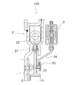
図1に示すように、ダンパ装置100は、ダンパ装置本体2(回転部材の一例)と、動吸振器3と、を有している。ダンパ装置100は、エンジンからのトルクを伝達するとともに、回転速度変動を減衰させるように構成されている。ダンパ装置100は、回転軸Oを中心に回転可能に配置されている。このダンパ装置100は、乾式型のダンパ装置100である。すなわち、ダンパ装置100は、粘性流体で充填されていないドライ環境下に配置されている。そして、後述する入力部材21や出力部材22がドライ環境下で回転する。 [Damper device]
As shown in FIG. 1, thedamper device 100 includes a damper device body 2 (an example of a rotating member) and a dynamic vibration absorber 3. The damper device 100 is configured to transmit torque from the engine and attenuate rotational speed fluctuations. The damper device 100 is disposed so as to be rotatable about the rotation axis O. The damper device 100 is a dry type damper device 100. That is, the damper device 100 is disposed in a dry environment that is not filled with a viscous fluid. And the input member 21 and the output member 22 mentioned later rotate in a dry environment.
図1に示すように、ダンパ装置100は、ダンパ装置本体2(回転部材の一例)と、動吸振器3と、を有している。ダンパ装置100は、エンジンからのトルクを伝達するとともに、回転速度変動を減衰させるように構成されている。ダンパ装置100は、回転軸Oを中心に回転可能に配置されている。このダンパ装置100は、乾式型のダンパ装置100である。すなわち、ダンパ装置100は、粘性流体で充填されていないドライ環境下に配置されている。そして、後述する入力部材21や出力部材22がドライ環境下で回転する。 [Damper device]
As shown in FIG. 1, the
[ダンパ装置本体]
ダンパ装置本体2は、入力部材21、及び出力部材22を有している。入力部材21は、例えばエンジンからのトルクが入力されるフライホイールである。入力部材21は、エンジンのクランクシャフトに固定されている。 [Damper device body]
Thedamper device body 2 includes an input member 21 and an output member 22. The input member 21 is a flywheel to which torque from an engine is input, for example. The input member 21 is fixed to the crankshaft of the engine.
ダンパ装置本体2は、入力部材21、及び出力部材22を有している。入力部材21は、例えばエンジンからのトルクが入力されるフライホイールである。入力部材21は、エンジンのクランクシャフトに固定されている。 [Damper device body]
The
入力部材21は、円板状である。入力部材21は、収容空間21aを有している。収容空間21aは、周方向に延びている。この収容空間21a内に、後述する弾性部材23が収容されている。また、収容空間21a内には、粘性流体が充填されていてもよい。例えば、グリスが収容空間21a内に充填されていてもよい。
The input member 21 has a disk shape. The input member 21 has an accommodation space 21a. The accommodation space 21a extends in the circumferential direction. An elastic member 23 to be described later is accommodated in the accommodation space 21a. In addition, the accommodating space 21a may be filled with a viscous fluid. For example, grease may be filled in the accommodation space 21a.
入力部材21は、入力プレート21bと、収容プレート21cとを有している。この入力プレート21bと収容プレート21cとによって、収容空間21aが形成されている。
また、入力部材21は、リングギア21dを有している。リングギア21dは、入力プレート21bに固定されている。 Theinput member 21 has an input plate 21b and an accommodation plate 21c. An accommodation space 21a is formed by the input plate 21b and the accommodation plate 21c.
Theinput member 21 has a ring gear 21d. The ring gear 21d is fixed to the input plate 21b.
また、入力部材21は、リングギア21dを有している。リングギア21dは、入力プレート21bに固定されている。 The
The
出力部材22は、入力部材21に入力されたトルクを出力する。出力部材22は、入力部材21と相対回転可能に連結されている。詳細には、ダンパ装置本体2は、複数の弾性部材23を有している。弾性部材23は、例えばコイルスプリングである。この弾性部材23は、入力部材21と出力部材22とを弾性的に連結している。
The output member 22 outputs the torque input to the input member 21. The output member 22 is connected to the input member 21 so as to be relatively rotatable. Specifically, the damper device main body 2 has a plurality of elastic members 23. The elastic member 23 is, for example, a coil spring. The elastic member 23 elastically connects the input member 21 and the output member 22.
[動吸振器]
動吸振器3は、ダンパ装置本体2に取り付けられている。詳細には、動吸振器3は、ダンパ装置本体2の入力部材21に取り付けられている。動吸振器3は、ダンパ装置本体2と軸方向において並んで配置されている。すなわち、軸方向視において、動吸振器3は、ダンパ装置本体2と重複するように配置されている。 [Dynamic vibration absorber]
Thedynamic vibration absorber 3 is attached to the damper device main body 2. Specifically, the dynamic vibration absorber 3 is attached to the input member 21 of the damper device main body 2. The dynamic vibration absorber 3 is arranged side by side with the damper device main body 2 in the axial direction. That is, the dynamic vibration absorber 3 is disposed so as to overlap the damper device main body 2 when viewed in the axial direction.
動吸振器3は、ダンパ装置本体2に取り付けられている。詳細には、動吸振器3は、ダンパ装置本体2の入力部材21に取り付けられている。動吸振器3は、ダンパ装置本体2と軸方向において並んで配置されている。すなわち、軸方向視において、動吸振器3は、ダンパ装置本体2と重複するように配置されている。 [Dynamic vibration absorber]
The
動吸振器3は、ダンパ装置本体2の振動を減衰するように構成されている。図2に示すように、動吸振器3は、質量体31a、31b、ハウジング32、粘性流体33、ベース部材34、及びトルク制限部50を有している。また、動吸振器3は、第1蓋部材35a、第2蓋部材35b、及び複数のコイルスプリング36を有している。なお、本実施形態では、質量体は、第1質量体31a及び第2質量体31bから構成されている。
The dynamic vibration absorber 3 is configured to attenuate the vibration of the damper device body 2. As shown in FIG. 2, the dynamic vibration absorber 3 includes mass bodies 31 a and 31 b, a housing 32, a viscous fluid 33, a base member 34, and a torque limiting unit 50. The dynamic vibration absorber 3 includes a first lid member 35a, a second lid member 35b, and a plurality of coil springs 36. In the present embodiment, the mass body is composed of a first mass body 31a and a second mass body 31b.
図1に示すように、ベース部材34は、回転軸Oを中心に回転可能に配置されている。ベース部材34は、トルク制限部50を介して、ダンパ装置本体2に取り付けられている。詳細には、ベース部材34は、トルク制限部50を介して、ダンパ装置本体2の入力部材21に取り付けられている。ベース部材34は、ダンパ装置本体2から入力されるトルクが所定の閾値未満の場合、ダンパ装置本体2と一体的に回転する。詳細には、ベース部材34は、ダンパ装置本体2の入力部材21から入力されるトルクが所定の閾値未満の場合、ダンパ装置本体2の入力部材21と一体的に回転する。
As shown in FIG. 1, the base member 34 is disposed so as to be rotatable about the rotation axis O. The base member 34 is attached to the damper device main body 2 via the torque limiting unit 50. Specifically, the base member 34 is attached to the input member 21 of the damper device main body 2 via the torque limiting unit 50. The base member 34 rotates integrally with the damper device main body 2 when the torque input from the damper device main body 2 is less than a predetermined threshold. Specifically, the base member 34 rotates integrally with the input member 21 of the damper device main body 2 when the torque input from the input member 21 of the damper device main body 2 is less than a predetermined threshold.
ベース部材34は、環状である。ベース部材34の内周端部が、トルク制限部50を介して、ダンパ装置本体2に取り付けられている。
The base member 34 is annular. An inner peripheral end portion of the base member 34 is attached to the damper device main body 2 via a torque limiting portion 50.
図3に示すように、ベース部材34は、複数の収容部341を有している。各収容部341は、円周方向に互いに間隔をあけて配置されている。各収容部341は円周方向に延びている。隣り合う収容部341の間には、長孔342が形成されている。長孔342は、円周方向に延びており、収容部341と同じ円周上に配置されている。
As shown in FIG. 3, the base member 34 has a plurality of accommodating portions 341. Each accommodating part 341 is arrange | positioned at intervals in the circumferential direction. Each accommodating portion 341 extends in the circumferential direction. A long hole 342 is formed between the adjacent accommodating portions 341. The long hole 342 extends in the circumferential direction and is disposed on the same circumference as the housing portion 341.
図2に示すように、トルク制限部50は、ダンパ装置本体2の入力部材21からベース部材34に入力されるトルクの伝達を制限する。詳細には、トルク制限部50は、ベース部材34に入力されるトルクが所定の閾値未満の場合は、ベース部材34を入力部材21と一体的に回転させる。すなわち、トルク制限部50は、入力部材21からのトルクをベース部材34に伝達する。一方、ベース部材34に入力されるトルクが所定の閾値以上の場合、トルク制限部50は、ベース部材34を入力部材21と相対的に回転させる。すなわち、トルク制限部50は、入力部材21からのトルクをベース部材34に伝達しない。
2, the torque limiting unit 50 limits the transmission of torque input from the input member 21 of the damper device body 2 to the base member 34. Specifically, the torque limiting unit 50 rotates the base member 34 integrally with the input member 21 when the torque input to the base member 34 is less than a predetermined threshold value. That is, the torque limiting unit 50 transmits the torque from the input member 21 to the base member 34. On the other hand, when the torque input to the base member 34 is equal to or greater than a predetermined threshold, the torque limiting unit 50 rotates the base member 34 relative to the input member 21. That is, the torque limiting unit 50 does not transmit the torque from the input member 21 to the base member 34.
トルク制限部50は、摩擦力によって、ダンパ装置本体2からベース部材34に入力されるトルクの伝達を制限する。トルク制限部50は、付勢部材51を有している。付勢部材51は、軸方向において、ベース部材34を入力部材21に向かって付勢している。付勢部材51は、ベース部材34の内周端部と当接している。ベース部材34は、入力部材21と付勢部材51とによって挟持されている。
The torque limiter 50 limits the transmission of torque input from the damper device body 2 to the base member 34 by the frictional force. The torque limiting unit 50 has a biasing member 51. The biasing member 51 biases the base member 34 toward the input member 21 in the axial direction. The biasing member 51 is in contact with the inner peripheral end of the base member 34. The base member 34 is sandwiched between the input member 21 and the biasing member 51.
ベース部材34に入力されるトルクが所定の閾値未満の場合、ベース部材34は、入力部材21との静止摩擦力によって、入力部材21と一体的に回転する。一方、ベース部材34に入力されるトルクが所定の閾値以上の場合、ベース部材34に最大静止摩擦力を超える力が掛かり、ベース部材34は入力部材21に対して相対回転する。なお、ベース部材34と入力部材21との間に摩擦材を介在させてもよい。
When the torque input to the base member 34 is less than a predetermined threshold value, the base member 34 rotates integrally with the input member 21 by a static frictional force with the input member 21. On the other hand, when the torque input to the base member 34 is equal to or greater than a predetermined threshold, a force exceeding the maximum static friction force is applied to the base member 34, and the base member 34 rotates relative to the input member 21. A friction material may be interposed between the base member 34 and the input member 21.
付勢部材51は、例えば、皿バネである。付勢部材51の外周端部がベース部材34と当接している。また、付勢部材51の内周端部が、後述する支持プレート52と当接している。
The biasing member 51 is, for example, a disc spring. The outer peripheral end of the urging member 51 is in contact with the base member 34. Further, the inner peripheral end of the urging member 51 is in contact with a support plate 52 described later.
トルク制限部50は、支持プレート52をさらに有している。支持プレート52は、軸方向において、付勢部材51を支持している。支持プレート52は、ベース部材34と軸方向において間隔をあけて配置されている。付勢部材51は、軸方向において、ベース部材34と支持プレート52との間に配置されている。付勢部材51は、軸方向において、一方の端部がベース部材34に当接し、他方の端部が支持プレート52に当接している。付勢部材51は、圧縮された状態で、ベース部材34と支持プレート52との間に配置されている。
The torque limiting unit 50 further includes a support plate 52. The support plate 52 supports the biasing member 51 in the axial direction. The support plate 52 is disposed at a distance from the base member 34 in the axial direction. The biasing member 51 is disposed between the base member 34 and the support plate 52 in the axial direction. The biasing member 51 has one end in contact with the base member 34 and the other end in contact with the support plate 52 in the axial direction. The urging member 51 is disposed between the base member 34 and the support plate 52 in a compressed state.
トルク制限部50はスペーサ53をさらに有している。スペーサ53は円筒状である。スペーサ53は、軸方向において、入力部材21と支持プレート52との間に配置されている。リベット101が、入力部材21、支持プレート52、及びスペーサ53を締結している。スペーサ53は、軸方向において、入力部材21と支持プレート52とのスペースを確保している。このスペーサ53によって確保された軸方向のスペースに、ベース部材34と付勢部材51とが配置されている。
The torque limiting unit 50 further has a spacer 53. The spacer 53 is cylindrical. The spacer 53 is disposed between the input member 21 and the support plate 52 in the axial direction. The rivet 101 fastens the input member 21, the support plate 52, and the spacer 53. The spacer 53 secures a space between the input member 21 and the support plate 52 in the axial direction. The base member 34 and the urging member 51 are disposed in the axial space secured by the spacer 53.
第1及び第2質量体31a、31bは、ベース部材34に対して相対回転可能である。また、第1及び第2質量体31a、31bは、回転軸Oを中心に回転可能である。
The first and second mass bodies 31 a and 31 b can be rotated relative to the base member 34. Further, the first and second mass bodies 31 a and 31 b can rotate around the rotation axis O.
第1及び第2質量体31a、31bは、板金部材をプレス加工して形成されている。第1及び第2質量体31a、31bは、ベース部材34の軸方向両側に配置されている。すなわち、第1質量体31aは、ベース部材34のエンジン側に配置され、第2質量体31bは、ベース部材34のトランスミッション側に配置される。
The first and second mass bodies 31a and 31b are formed by pressing a sheet metal member. The first and second mass bodies 31 a and 31 b are disposed on both sides of the base member 34 in the axial direction. That is, the first mass body 31 a is disposed on the engine side of the base member 34, and the second mass body 31 b is disposed on the transmission side of the base member 34.
図4に示すように、第1及び第2質量体31a、31bは、複数の収容部311を有している。各収容部311は、周方向に互いに間隔をあけて配置されている。各収容部311は、ベース部材34の各収容部341に対応する位置に配置されている。また、第1及び第2質量体31a、31bは、ベース部材34の長孔342の円周方向中央位置に対応する位置に貫通孔312を有している。
As shown in FIG. 4, the first and second mass bodies 31 a and 31 b have a plurality of accommodating portions 311. Each accommodating part 311 is arrange | positioned at intervals in the circumferential direction. Each accommodating portion 311 is disposed at a position corresponding to each accommodating portion 341 of the base member 34. The first and second mass bodies 31 a and 31 b have a through hole 312 at a position corresponding to the center position in the circumferential direction of the long hole 342 of the base member 34.
図2に示すように、第1蓋部材35aは、環状であって、第1質量体31aのエンジン側に配置されている。すなわち、第1蓋部材35aと、ベース部材34とによって、第1質量体31aを挟み込んでいる。図5に拡大して示すように、第1蓋部材35aには、第1質量体31aの貫通孔312に対応する位置に貫通孔351が形成されている。
As shown in FIG. 2, the first lid member 35a is annular and is disposed on the engine side of the first mass body 31a. That is, the first mass body 31 a is sandwiched between the first lid member 35 a and the base member 34. As shown in an enlarged view in FIG. 5, a through hole 351 is formed in the first lid member 35a at a position corresponding to the through hole 312 of the first mass body 31a.
図2に示すように、第2蓋部材35bは、第2質量体31bのトランスミッション側に配置されている。すなわち、第2蓋部材35bとベース部材34とによって、第2質量体31bを挟み込んでいる。図5に拡大して示すように、第2蓋部材35bは、環状の部材である。第2蓋部材35bには、第2質量体31bの貫通孔312に対応する位置に貫通孔351が形成されている。
As shown in FIG. 2, the second lid member 35b is disposed on the transmission side of the second mass body 31b. That is, the second mass body 31b is sandwiched between the second lid member 35b and the base member 34. As shown in an enlarged view in FIG. 5, the second lid member 35b is an annular member. A through hole 351 is formed in the second lid member 35b at a position corresponding to the through hole 312 of the second mass body 31b.
図2~図4に示すように、複数のコイルスプリング36は、それぞれベース部材34の収容部341及び第1及び第2質量体31a、31bの収容部311に収容されている。そして、コイルスプリング36の両端部はベース部材34及び第1及び第2質量体31a、31bの収容部341,311の円周方向端部に当接している。
2 to 4, the plurality of coil springs 36 are housed in the housing portion 341 of the base member 34 and the housing portions 311 of the first and second mass bodies 31a and 31b, respectively. Both end portions of the coil spring 36 are in contact with the circumferential end portions of the base member 34 and the accommodating portions 341 and 311 of the first and second mass bodies 31a and 31b.
図5に示すように、ストップピン37は、軸方向の中央部に大径胴部371を有し、その両側に小径胴部372を有している。
As shown in FIG. 5, the stop pin 37 has a large-diameter trunk 371 at the center in the axial direction and small-diameter trunks 372 on both sides thereof.
大径胴部371は、第1及び第2質量体31a、31bの貫通孔312より大径で、かつベース部材34の長孔342の径(径方向寸法)よりも小径である。また、大径胴部371の厚みは、ベース部材34の厚みより若干厚く形成されている。
The large diameter body 371 is larger in diameter than the through holes 312 of the first and second mass bodies 31a and 31b, and smaller in diameter than the diameter (diameter dimension) of the long hole 342 of the base member 34. Further, the thickness of the large-diameter body portion 371 is slightly thicker than the thickness of the base member 34.
小径胴部372は第1及び第2質量体31a、31bの貫通孔312及び両蓋部材35a,35bの貫通孔351を挿通している。そして、小径胴部372の頭部をかしめることによって、ベース部材34の軸方向両側に第1及び第2質量体31a、31b及び両蓋部材35a,35bが固定されている。
The small diameter body 372 is inserted through the through holes 312 of the first and second mass bodies 31a and 31b and the through holes 351 of the lid members 35a and 35b. The first and second mass bodies 31a and 31b and the lid members 35a and 35b are fixed to both sides of the base member 34 in the axial direction by caulking the head of the small diameter body 372.
以上のような構成により、ベース部材34は、第1及び第2質量体31a、31b及び2つの蓋部材35a,35bに対して、ストップピン37がベース部材34の長孔342で移動し得る範囲で相対回転が可能である。そして、ストップピン37の大径胴部371が長孔342の端部に当接することによって、両者の相対回転が規制される。
With the configuration as described above, the base member 34 has a range in which the stop pin 37 can move in the long hole 342 of the base member 34 with respect to the first and second mass bodies 31a and 31b and the two lid members 35a and 35b. Relative rotation is possible. Then, when the large-diameter body portion 371 of the stop pin 37 abuts against the end portion of the long hole 342, the relative rotation of both is restricted.
図2に示すように、ハウジング32は、第1及び第2質量体31a、31bを収容するように構成されている。また、ハウジング32は、コイルスプリング36なども収容している。ハウジング32は、例えばリベットなどの締結部材102などによって、ベース部材34に取り付けられている。
As shown in FIG. 2, the housing 32 is configured to accommodate the first and second mass bodies 31a and 31b. The housing 32 also houses a coil spring 36 and the like. The housing 32 is attached to the base member 34 by a fastening member 102 such as a rivet.
ハウジング32は、2枚の環状プレート321から構成されている。この各環状プレート321は、内部空間を形成している。すなわち、各環状プレート321は、軸方向において、並んで配置されている。そして、各環状プレート321は、互いから離れる方向に膨らむことによって内部空間が形成されている。
The housing 32 is composed of two annular plates 321. Each annular plate 321 forms an internal space. That is, the annular plates 321 are arranged side by side in the axial direction. Each annular plate 321 swells in a direction away from each other to form an internal space.
各環状プレート321は、外周端部に外周フランジ322を有している。各環状プレート321は、この外周フランジ322において、リベットなどの締結部材103によって、互いに固定されている。すなわち、各環状プレート321の外周フランジ322同士が互いに当接し合っている。そして、各外周フランジ322を貫通する締結部材103によって、各外周フランジ322同士が固定されている。なお、各外周フランジ322同士は、溶接などによって互いに固定されていてもよい。
Each annular plate 321 has an outer peripheral flange 322 at the outer peripheral end. The annular plates 321 are fixed to each other at the outer peripheral flange 322 by a fastening member 103 such as a rivet. That is, the outer peripheral flanges 322 of the annular plates 321 are in contact with each other. The outer peripheral flanges 322 are fixed to each other by the fastening member 103 penetrating the outer peripheral flanges 322. The outer peripheral flanges 322 may be fixed to each other by welding or the like.
また、各環状プレート321は、内周端部に内周フランジ323を有している。この各内周フランジ323は、ベース部材34に当接している。すなわち、各内周フランジ323は、ベース部材34を挟むように配置されている。そして、各内周フランジ323及びベース部材34を貫通する締結部材102によって、各内周フランジ323はベース部材34に固定されている。なお、各内周フランジ323は、溶接などによってベース部材34に固定されていてもよい。
Each annular plate 321 has an inner peripheral flange 323 at the inner peripheral end. Each inner peripheral flange 323 is in contact with the base member 34. That is, each inner peripheral flange 323 is disposed so as to sandwich the base member 34. Each inner peripheral flange 323 is fixed to the base member 34 by a fastening member 102 that passes through each inner peripheral flange 323 and the base member 34. Each inner peripheral flange 323 may be fixed to the base member 34 by welding or the like.
このハウジング32内には、粘性流体33が充填されている。粘性流体33としては、例えば、潤滑油などを用いることができる。
The housing 32 is filled with a viscous fluid 33. As the viscous fluid 33, for example, lubricating oil or the like can be used.
[変形例]
以上、本発明の実施形態について説明したが、本発明はこれらに限定されるものではなく、本発明の趣旨を逸脱しない限りにおいて種々の変更が可能である。 [Modification]
As mentioned above, although embodiment of this invention was described, this invention is not limited to these, A various change is possible unless it deviates from the meaning of this invention.
以上、本発明の実施形態について説明したが、本発明はこれらに限定されるものではなく、本発明の趣旨を逸脱しない限りにおいて種々の変更が可能である。 [Modification]
As mentioned above, although embodiment of this invention was described, this invention is not limited to these, A various change is possible unless it deviates from the meaning of this invention.
変形例1
上記実施形態では、動吸振器3は、ダンパ装置本体2の入力部材21に取り付けられているが、ダンパ装置100の構成はこれに限定されない。例えば、図6に示すように、動吸振器3は、ダンパ装置本体2の出力部材22に取り付けられていてもよい。詳細には、動吸振器3のベース部材34が、トルク制限部50を介して、出力部材22に取り付けられている。 Modification 1
In the said embodiment, although thedynamic vibration absorber 3 is attached to the input member 21 of the damper apparatus main body 2, the structure of the damper apparatus 100 is not limited to this. For example, as shown in FIG. 6, the dynamic vibration absorber 3 may be attached to the output member 22 of the damper device main body 2. Specifically, the base member 34 of the dynamic vibration absorber 3 is attached to the output member 22 via the torque limiting unit 50.
上記実施形態では、動吸振器3は、ダンパ装置本体2の入力部材21に取り付けられているが、ダンパ装置100の構成はこれに限定されない。例えば、図6に示すように、動吸振器3は、ダンパ装置本体2の出力部材22に取り付けられていてもよい。詳細には、動吸振器3のベース部材34が、トルク制限部50を介して、出力部材22に取り付けられている。 Modification 1
In the said embodiment, although the
変形例2
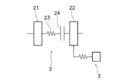
また、図7~図12に示すように、動吸振器3は、トルク制限部50を介して、ダンパ装置本体2の種々の場所に取り付けることができる。なお、図7~図12において、ダンパ装置本体2は、入力部材21、出力部材22、弾性部材23、及びクラッチ部24を有している。入力部材21と出力部材22との間に弾性部材23が設けられており、入力部材21と出力部材22とが弾性的に連結されている。Modification 2
Further, as shown in FIGS. 7 to 12, thedynamic vibration absorber 3 can be attached to various places of the damper device main body 2 via the torque limiting portion 50. 7 to 12, the damper device body 2 includes an input member 21, an output member 22, an elastic member 23, and a clutch portion 24. An elastic member 23 is provided between the input member 21 and the output member 22, and the input member 21 and the output member 22 are elastically connected.
また、図7~図12に示すように、動吸振器3は、トルク制限部50を介して、ダンパ装置本体2の種々の場所に取り付けることができる。なお、図7~図12において、ダンパ装置本体2は、入力部材21、出力部材22、弾性部材23、及びクラッチ部24を有している。入力部材21と出力部材22との間に弾性部材23が設けられており、入力部材21と出力部材22とが弾性的に連結されている。
Further, as shown in FIGS. 7 to 12, the
図7に示すダンパ装置本体2では、入力部材21と弾性部材23との間にクラッチ部24が設けられている。そして、動吸振器3が出力部材22に取り付けられている。
In the damper device body 2 shown in FIG. 7, a clutch portion 24 is provided between the input member 21 and the elastic member 23. The dynamic vibration absorber 3 is attached to the output member 22.
図8に示すダンパ装置本体2では、弾性部材23と出力部材22との間にクラッチ部24が設けられている。そして、動吸振器3が出力部材22に取り付けられている。
In the damper device body 2 shown in FIG. 8, a clutch portion 24 is provided between the elastic member 23 and the output member 22. The dynamic vibration absorber 3 is attached to the output member 22.
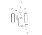
図9に示すダンパ装置本体2では、弾性部材23と出力部材22との間にクラッチ部24が設けられている。そして、動吸振器3が弾性部材23とクラッチ部24との間に取り付けられている。
In the damper device body 2 shown in FIG. 9, a clutch portion 24 is provided between the elastic member 23 and the output member 22. The dynamic vibration absorber 3 is attached between the elastic member 23 and the clutch portion 24.
図10に示すダンパ装置本体2では、弾性部材23と出力部材22との間にクラッチ部24が設けられている。そして、動吸振器3が入力部材21に取り付けられている。
In the damper device body 2 shown in FIG. 10, a clutch portion 24 is provided between the elastic member 23 and the output member 22. The dynamic vibration absorber 3 is attached to the input member 21.
図11に示すダンパ装置本体2では、入力部材21と弾性部材23との間にクラッチ部24が設けられている。そして、動吸振器3が入力部材21に取り付けられている。
In the damper device body 2 shown in FIG. 11, a clutch portion 24 is provided between the input member 21 and the elastic member 23. The dynamic vibration absorber 3 is attached to the input member 21.
図12に示すダンパ装置本体2では、入力部材21と弾性部材23との間にクラッチ部24が設けられている。そして、動吸振器3がクラッチ部24と弾性部材23との間に取り付けられている。
In the damper device body 2 shown in FIG. 12, a clutch portion 24 is provided between the input member 21 and the elastic member 23. The dynamic vibration absorber 3 is attached between the clutch portion 24 and the elastic member 23.
以上の各構成によれば、エンジン始動時において過大なトルクがダンパ装置本体2に入力されたときに、トルク制限部50がベース部材34にトルクが伝達することを制限することで、ダンパ装置本体2の損傷を効果的に防止することができる。また、急ブレーキ時などにおいてトランスミッション側から過大なトルクがダンパ装置本体2に入力されたときに、トルク制限部50がベース部材34にトルクが伝達することを制限することで、ダンパ装置本体2の損傷を効果的に防止することができる。
According to each of the above configurations, when excessive torque is input to the damper device main body 2 at the time of starting the engine, the torque limiting unit 50 restricts the transmission of torque to the base member 34, whereby the damper device main body. 2 damage can be effectively prevented. In addition, when excessive torque is input to the damper device main body 2 from the transmission side, for example, during sudden braking, the torque limiting unit 50 restricts the torque from being transmitted to the base member 34, so that the damper device main body 2 Damage can be effectively prevented.
変形例3
図13に示すように、ダンパ装置本体2は、入力部材21、出力部材22、第1及び第2弾性部材23a、23b、並びに中間部材25と、を有していてもよい。この場合、動吸振器3は、中間部材25に取り付けられていてもよい。第1及び第2弾性部材23a、23bは、入力部材21と出力部材22とを弾性的に連結する。例えば、第1弾性部材23aは、外周側に配置された外周側トーションスプリングであり、第2弾性部材23bは、内周側に配置された内周側トーションスプリングである。中間部材25は、第1弾性部材23aと第2弾性部材23bとを連結している。例えば、中間部材25は、第1弾性部材23aと第2弾性部材23bとを直列に連結している。そして、動吸振器3は、中間部材25に取り付けられる。Modification 3
As shown in FIG. 13, thedamper device body 2 may include an input member 21, an output member 22, first and second elastic members 23 a and 23 b, and an intermediate member 25. In this case, the dynamic vibration absorber 3 may be attached to the intermediate member 25. The first and second elastic members 23 a and 23 b elastically connect the input member 21 and the output member 22. For example, the first elastic member 23a is an outer peripheral side torsion spring disposed on the outer peripheral side, and the second elastic member 23b is an inner peripheral side torsion spring disposed on the inner peripheral side. The intermediate member 25 connects the first elastic member 23a and the second elastic member 23b. For example, the intermediate member 25 connects the first elastic member 23a and the second elastic member 23b in series. The dynamic vibration absorber 3 is attached to the intermediate member 25.
図13に示すように、ダンパ装置本体2は、入力部材21、出力部材22、第1及び第2弾性部材23a、23b、並びに中間部材25と、を有していてもよい。この場合、動吸振器3は、中間部材25に取り付けられていてもよい。第1及び第2弾性部材23a、23bは、入力部材21と出力部材22とを弾性的に連結する。例えば、第1弾性部材23aは、外周側に配置された外周側トーションスプリングであり、第2弾性部材23bは、内周側に配置された内周側トーションスプリングである。中間部材25は、第1弾性部材23aと第2弾性部材23bとを連結している。例えば、中間部材25は、第1弾性部材23aと第2弾性部材23bとを直列に連結している。そして、動吸振器3は、中間部材25に取り付けられる。
As shown in FIG. 13, the
変形例4
動吸振器3の構成は、上記実施形態の構成に限定されない。例えば、図14及び図15に示すように、動吸振器3の第1及び第2質量体31a、31bは、周方向に揺動可能にベース部材34に取り付けられていてもよい。そして、この第1及び第2質量体31a、31bの揺動によって回転変動を減衰するような構成とすることができる。この第1及び第2質量体31a、31bの揺動中心Sは、ダンパ装置100の回転軸Oとは異なる位置に配置される。 Modification 4
The structure of thedynamic vibration absorber 3 is not limited to the structure of the said embodiment. For example, as shown in FIGS. 14 and 15, the first and second mass bodies 31 a and 31 b of the dynamic vibration absorber 3 may be attached to the base member 34 so as to be swingable in the circumferential direction. And it can be set as the structure which attenuates a rotation fluctuation | variation by rocking | fluctuation of this 1st and 2nd mass bodies 31a and 31b. The swing center S of the first and second mass bodies 31 a and 31 b is disposed at a position different from the rotational axis O of the damper device 100.
動吸振器3の構成は、上記実施形態の構成に限定されない。例えば、図14及び図15に示すように、動吸振器3の第1及び第2質量体31a、31bは、周方向に揺動可能にベース部材34に取り付けられていてもよい。そして、この第1及び第2質量体31a、31bの揺動によって回転変動を減衰するような構成とすることができる。この第1及び第2質量体31a、31bの揺動中心Sは、ダンパ装置100の回転軸Oとは異なる位置に配置される。 Modification 4
The structure of the
詳細には、ベース部材34に、円弧状のスリット343が形成されている。スリット343は、ダンパ装置100の回転軸Oから所定距離R1隔てた点Sを中心とした半径R2の円弧状に形成されている。なお、スリット343は、回転方向に延びている。
Specifically, an arc-shaped slit 343 is formed in the base member 34. The slit 343 is formed in an arc shape having a radius R <b> 2 centered on a point S separated from the rotation axis O of the damper device 100 by a predetermined distance R <b> 1. The slit 343 extends in the rotation direction.
このスリット343内に、カラー38が配置されている。カラー38は円筒状である。カラー38の直径は、スリット343の径方向の幅よりも小さい。また、カラー38の長さは、ベース部材34よりも長い。カラー38は、軸方向において、第1及び第2質量体31a、31bの間に配置されている。リベット39によって、第1質量体31a、第2質量体31b、及びカラー38が固定されている。第1及び第2質量体31a、31bは、このスリット343に沿って揺動する。なお、図14及び図15では、図解を容易にするため、ハウジング32の記載を省略している。
A collar 38 is disposed in the slit 343. The collar 38 is cylindrical. The diameter of the collar 38 is smaller than the radial width of the slit 343. The length of the collar 38 is longer than that of the base member 34. The collar 38 is disposed between the first and second mass bodies 31a and 31b in the axial direction. The first mass body 31a, the second mass body 31b, and the collar 38 are fixed by the rivet 39. The first and second mass bodies 31 a and 31 b swing along the slit 343. In FIGS. 14 and 15, the housing 32 is not shown for easy illustration.
変形例5
動吸振器3の構成は、上記実施形態の構成に限定されない。例えば、図16に示すように、動吸振器3は、質量体31と、遠心子40と、カム機構41とを有している。また、動吸振器3は、コイルスプリング42を有していてもよい。 Modification 5
The structure of thedynamic vibration absorber 3 is not limited to the structure of the said embodiment. For example, as shown in FIG. 16, the dynamic vibration absorber 3 includes a mass body 31, a centrifuge 40, and a cam mechanism 41. The dynamic vibration absorber 3 may have a coil spring 42.
動吸振器3の構成は、上記実施形態の構成に限定されない。例えば、図16に示すように、動吸振器3は、質量体31と、遠心子40と、カム機構41とを有している。また、動吸振器3は、コイルスプリング42を有していてもよい。 Modification 5
The structure of the
質量体31は、例えば、環状であって、ベース部材34の径方向外側に配置されている。径方向において、質量体31とベース部材34とは、間隔をあけて配置されている。なお、質量体31とベース部材34とは、径方向において、並ぶように配置されている。すなわち、径方向視において、質量体31とベース部材34とは重複している。
The mass body 31 is, for example, annular, and is disposed on the outer side in the radial direction of the base member 34. In the radial direction, the mass body 31 and the base member 34 are arranged at an interval. Note that the mass body 31 and the base member 34 are arranged side by side in the radial direction. That is, the mass body 31 and the base member 34 overlap in the radial direction view.
質量体31及びベース部材34は、回転軸Oを中心に回転する。質量体31とベース部材34とは、相対回転可能である。
The mass body 31 and the base member 34 rotate around the rotation axis O. The mass body 31 and the base member 34 are relatively rotatable.
遠心子40は、ベース部材34に配置されており、ベース部材34の回転による遠心力によって径方向の外側に移動可能である。より詳細には、図17に拡大して示すように、ベース部材34には、外周面に凹部344が設けられている。凹部344は、ベース部材34の外周面に、内周側の回転中心に向かって窪むように矩形状に形成されている。そして、この凹部344に遠心子40が径方向に移動可能に挿入されている。例えば、遠心子40及び凹部344は、遠心子40の側面と凹部344との間の摩擦係数が0.1以下になるように設定されている。また、遠心子40は、ベース部材34とほぼ同じ厚みを有するプレートで、かつ外周面401が円弧状に形成されている。また、遠心子40の外周面401には、内側に窪むコロ収容部402が形成されている。
The centrifuge 40 is disposed on the base member 34 and can be moved outward in the radial direction by the centrifugal force generated by the rotation of the base member 34. More specifically, as shown in an enlarged view in FIG. 17, the base member 34 is provided with a recess 344 on the outer peripheral surface. The concave portion 344 is formed in a rectangular shape on the outer peripheral surface of the base member 34 so as to be recessed toward the center of rotation on the inner peripheral side. The centrifuge 40 is inserted into the recess 344 so as to be movable in the radial direction. For example, the centrifuge 40 and the recess 344 are set such that the friction coefficient between the side surface of the centrifuge 40 and the recess 344 is 0.1 or less. The centrifuge 40 is a plate having substantially the same thickness as the base member 34, and the outer peripheral surface 401 is formed in an arc shape. Further, a roller accommodating portion 402 that is recessed inward is formed on the outer peripheral surface 401 of the centrifuge 40.
カム機構41は、カムフォロアとしてのコロ411と、質量体31の内周面に形成されたカム412と、から構成されている。コロ411は遠心子40のコロ収容部402に装着されており、遠心子40とともに径方向に移動自在である。なお、コロ411は、コロ収容部402において、回転自在であっても、固定されていてもよい。カム412は、コロ411が当接する円弧状の面である。ベース部材34と質量体31とが所定の角度範囲で相対回転した際には、コロ411はこのカム412に沿って移動する。
The cam mechanism 41 includes a roller 411 as a cam follower and a cam 412 formed on the inner peripheral surface of the mass body 31. The roller 411 is attached to the roller accommodating portion 402 of the centrifuge 40 and is movable in the radial direction together with the centrifuge 40. The roller 411 may be rotatable or fixed in the roller housing portion 402. The cam 412 is an arcuate surface with which the roller 411 contacts. When the base member 34 and the mass body 31 are relatively rotated within a predetermined angle range, the roller 411 moves along the cam 412.
コロ411とカム412との接触によって、ベース部材34と質量体31との間に回転位相差が生じたときに、遠心子40及びコロ411に生じた遠心力は、回転位相差が小さくなるような円周方向の力に変換される。
When a rotational phase difference is generated between the base member 34 and the mass body 31 due to contact between the roller 411 and the cam 412, the centrifugal force generated in the centrifuge 40 and the roller 411 is reduced in rotational phase difference. Is converted into a force in the circumferential direction.
コイルスプリング42は、凹部344の底面と遠心子40の径方向内側面との間に配置され、遠心子40を径方向外側に付勢している。このコイルスプリング42の付勢力によって、遠心子40及びコロ411は質量体31のカム412に押し付けられている。したがって、ベース部材34が回転していない状態で、遠心子40に遠心力が作用していない場合でも、コロ411はカム412に当接する。
The coil spring 42 is disposed between the bottom surface of the recess 344 and the radially inner side surface of the centrifuge 40, and urges the centrifuge 40 radially outward. The centrifuge 40 and the roller 411 are pressed against the cam 412 of the mass body 31 by the urging force of the coil spring 42. Therefore, even when the centrifugal force is not acting on the centrifuge 40 with the base member 34 not rotating, the roller 411 contacts the cam 412.
[カム機構41の作動]
図17及び図18を用いて、カム機構41の作動(トルク変動の抑制)について説明する。 [Operation of cam mechanism 41]
The operation of the cam mechanism 41 (suppression of torque fluctuation) will be described with reference to FIGS. 17 and 18.
図17及び図18を用いて、カム機構41の作動(トルク変動の抑制)について説明する。 [Operation of cam mechanism 41]
The operation of the cam mechanism 41 (suppression of torque fluctuation) will be described with reference to FIGS. 17 and 18.
ダンパ装置本体2に伝達されたトルクは、その値が所定の閾値未満の場合、ベース部材34に伝達される。トルク伝達時にトルク変動がない場合は、図17に示すような状態で、ベース部材34及び質量体31は回転する。すなわち、カム機構41のコロ411はカム412のもっとも深い位置(円周方向の中央位置)に当接し、ベース部材34と質量体31との回転位相差は「0」である。
The torque transmitted to the damper device main body 2 is transmitted to the base member 34 when the value is less than a predetermined threshold value. When there is no torque fluctuation during torque transmission, the base member 34 and the mass body 31 rotate in the state shown in FIG. That is, the roller 411 of the cam mechanism 41 contacts the deepest position (circumferential center position) of the cam 412, and the rotational phase difference between the base member 34 and the mass body 31 is “0”.
前述のように、ベース部材34と質量体31との間の回転方向の相対変位を、「回転位相差」と称しているが、これらは、図17及び図18では、遠心子40及びコロ411の円周方向の中央位置と、カム412の円周方向の中央位置と、のずれを示すものである。
As described above, the relative displacement in the rotation direction between the base member 34 and the mass body 31 is referred to as a “rotation phase difference”, which is the centrifuge 40 and the roller 411 in FIGS. 17 and 18. The difference between the center position in the circumferential direction and the center position in the circumferential direction of the cam 412 is shown.
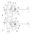
一方、トルクの伝達時にトルク変動が存在すると、図18(a)及び図18(b)に示すように、ベース部材34と質量体31との間には、回転位相差±θが生じる。図18(a)は+R側に回転位相差+θが生じた場合を示し、図18(b)は-R側に回転位相差-θが生じた場合を示している。
On the other hand, if torque fluctuation exists during torque transmission, a rotational phase difference ± θ is generated between the base member 34 and the mass 31 as shown in FIGS. 18 (a) and 18 (b). FIG. 18A shows a case where a rotational phase difference + θ is generated on the + R side, and FIG. 18B shows a case where a rotational phase difference −θ is generated on the −R side.
図18(a)に示すように、ベース部材34と質量体31との間に回転位相差+θが生じた場合は、カム機構41のコロ411は、カム412に沿って相対的に図18の左側に移動する。このとき、遠心子40及びコロ411には遠心力が作用しているので、カム412からコロ411が受ける反力は、図18(a)のP0の方向及び大きさとなる。この反力P0によって、円周方向の第1分力P1と、遠心子40及びコロ411を回転中心に向かって移動させる方向の第2分力P2と、が発生する。
As shown in FIG. 18A, when a rotational phase difference + θ is generated between the base member 34 and the mass body 31, the roller 411 of the cam mechanism 41 is relatively moved along the cam 412 in FIG. Move to the left. At this time, since centrifugal force is acting on the centrifuge 40 and the roller 411, the reaction force received by the roller 411 from the cam 412 is in the direction and magnitude of P0 in FIG. The reaction force P0 generates a first component force P1 in the circumferential direction and a second component force P2 in a direction that moves the centrifuge 40 and the roller 411 toward the center of rotation.
そして、第1分力P1は、カム機構41を介してベース部材34を図18(a)の右方向に移動させる力となる。すなわち、ベース部材34と質量体31との回転位相差を小さくする方向の力が、ベース部材34に作用することになる。また、第2分力P2によって、遠心子40及びコロ411は、コイルスプリング42の付勢力に抗して、径方向内周側に移動させられる。
The first component force P1 is a force that moves the base member 34 to the right in FIG. 18A via the cam mechanism 41. That is, a force in the direction of reducing the rotational phase difference between the base member 34 and the mass body 31 acts on the base member 34. Further, the centrifuge 40 and the roller 411 are moved to the radially inner peripheral side against the urging force of the coil spring 42 by the second component force P2.
図18(b)は、ベース部材34と質量体31との間に回転位相差-θが生じた場合を示しており、カム機構41のコロ411の移動方向、反力P0、第1分力P1、及び第2分力P2の方向が図18(a)と異なるだけで、作動は同様である。
FIG. 18B shows a case where a rotational phase difference −θ is generated between the base member 34 and the mass body 31. The moving direction of the roller 411 of the cam mechanism 41, the reaction force P 0, and the first component force The operation is the same except that the directions of P1 and the second component force P2 are different from those in FIG.
以上のように、トルク変動によってベース部材34と質量体31との間に回転位相差が生じると、遠心子40に作用する遠心力及びカム機構41の作用によって、ベース部材34は、両者の回転位相差を小さくする方向の力(第1分力P1)を受ける。この力によって、トルク変動が抑制される。
As described above, when a rotational phase difference occurs between the base member 34 and the mass body 31 due to torque fluctuation, the base member 34 is rotated by the centrifugal force acting on the centrifuge 40 and the action of the cam mechanism 41. A force in the direction of decreasing the phase difference (first component force P1) is received. This force suppresses torque fluctuations.
以上のトルク変動を抑制する力は、遠心力、すなわちベース部材34の回転数によって変化するし、回転位相差及びカム412の形状によっても変化する。したがって、カム412の形状を適宜設定することによって、ダンパ装置100の特性を、エンジン仕様等に応じた最適な特性にすることができる。
The force that suppresses the above torque fluctuation changes depending on the centrifugal force, that is, the rotational speed of the base member 34, and also changes depending on the rotational phase difference and the shape of the cam 412. Therefore, by appropriately setting the shape of the cam 412, the characteristics of the damper device 100 can be optimized according to the engine specifications and the like.
例えば、カム412の形状は、同じ遠心力が作用している状態で、回転位相差に応じて第1分力P1が線形に変化するような形状にすることができる。また、カム412の形状は、回転位相差に応じて第1分力P1が非線形に変化する形状にすることができる。
For example, the shape of the cam 412 can be made such that the first component force P1 changes linearly according to the rotational phase difference in the state where the same centrifugal force is acting. In addition, the shape of the cam 412 can be a shape in which the first component force P1 changes nonlinearly according to the rotational phase difference.
3 :動吸振器
31a、31b :質量体
32 :ハウジング
33 :粘性流体
34 :ベース部材
40 :遠心子
41 :カム機構 3: Dynamic vibration absorbers 31a, 31b: Mass body 32: Housing 33: Viscous fluid 34: Base member 40: Centrifuge 41: Cam mechanism
31a、31b :質量体
32 :ハウジング
33 :粘性流体
34 :ベース部材
40 :遠心子
41 :カム機構 3:
Claims (6)
- 回転部材に取り付けられる動吸振器であって、
回転可能に配置されたベース部材と、
前記ベース部材に対して相対回転可能に取り付けられる質量体と、
前記回転部材から前記ベース部材に入力されるトルクの伝達を制限するトルク制限部と、
を備える、動吸振器。
A dynamic vibration absorber attached to a rotating member,
A base member rotatably arranged;
A mass body attached so as to be rotatable relative to the base member;
A torque limiting unit that limits transmission of torque input from the rotating member to the base member;
A dynamic vibration absorber.
- 前記トルク制限部は、前記ベース部材に入力されるトルクが閾値未満の場合、前記ベース部材を前記回転部材と一体回転させ、前記ベース部材に入力されるトルクが前記閾値以上の場合、前記ベース部を前記回転部材と相対回転させるよう構成される、
請求項1に記載の動吸振器。
When the torque input to the base member is less than a threshold, the torque limiting unit rotates the base member integrally with the rotating member, and when the torque input to the base member is equal to or greater than the threshold, the base unit Configured to rotate relative to the rotating member,
The dynamic vibration absorber according to claim 1.
- 前記トルク制限部は、前記ベース部材を前記回転部材に向かって付勢する付勢部材を有する、
請求項1に記載の動吸振器。
The torque limiting unit includes a biasing member that biases the base member toward the rotating member.
The dynamic vibration absorber according to claim 1.
- 前記ベース部材に取り付けられ、前記質量体を収容するハウジングと、
前記ハウジング内に充填される粘性流体と、
をさらに備える、請求項1から3のいずれかに記載の動吸振器。
A housing attached to the base member and containing the mass body;
A viscous fluid filled in the housing;
The dynamic vibration absorber according to any one of claims 1 to 3, further comprising:
- 前記質量体は、前記ベース部材に対して周方向に揺動し、前記ベース部材の回転中心と異なる位置に配置された揺動中心を有する、
請求項1から4のいずれかに記載の動吸振器。
The mass body swings in the circumferential direction with respect to the base member, and has a swing center disposed at a position different from the rotation center of the base member.
The dynamic vibration absorber according to any one of claims 1 to 4.
- 前記ベース部材の回転による遠心力を受けるように配置された遠心子と、
前記遠心子に作用する遠心力を円周方向の力に変換するカム機構と、
をさらに備える、請求項1から4のいずれかに記載の動吸振器。 A centrifuge arranged to receive centrifugal force due to rotation of the base member;
A cam mechanism for converting a centrifugal force acting on the centrifuge into a circumferential force;
The dynamic vibration absorber according to any one of claims 1 to 4, further comprising:
Priority Applications (2)
| Application Number | Priority Date | Filing Date | Title |
|---|---|---|---|
| US16/084,950 US10760644B2 (en) | 2016-07-19 | 2017-06-05 | Dynamic vibration absorber |
| CN201780024111.8A CN109073038A (en) | 2016-07-19 | 2017-06-05 | Dynamic shock-absorber |
Applications Claiming Priority (2)
| Application Number | Priority Date | Filing Date | Title |
|---|---|---|---|
| JP2016-141586 | 2016-07-19 | ||
| JP2016141586A JP2018013144A (en) | 2016-07-19 | 2016-07-19 | Dynamic vibration absorber |
Publications (1)
| Publication Number | Publication Date |
|---|---|
| WO2018016211A1 true WO2018016211A1 (en) | 2018-01-25 |
Family
ID=60992016
Family Applications (1)
| Application Number | Title | Priority Date | Filing Date |
|---|---|---|---|
| PCT/JP2017/020874 WO2018016211A1 (en) | 2016-07-19 | 2017-06-05 | Dynamic vibration absorber |
Country Status (4)
| Country | Link |
|---|---|
| US (1) | US10760644B2 (en) |
| JP (1) | JP2018013144A (en) |
| CN (1) | CN109073038A (en) |
| WO (1) | WO2018016211A1 (en) |
Families Citing this family (3)
| Publication number | Priority date | Publication date | Assignee | Title |
|---|---|---|---|---|
| JP6827311B2 (en) * | 2016-12-12 | 2021-02-10 | 株式会社エクセディ | Damper device |
| DE102019207826A1 (en) * | 2019-05-28 | 2020-12-03 | Zf Friedrichshafen Ag | Segmented vibration absorber |
| FR3097926B1 (en) * | 2019-06-27 | 2021-07-23 | Valeo Embrayages | Torque transmission device equipped with a torque limiter |
Citations (7)
| Publication number | Priority date | Publication date | Assignee | Title |
|---|---|---|---|---|
| JP2007182986A (en) * | 2005-12-05 | 2007-07-19 | Mitsubishi Heavy Ind Ltd | Vibration reducing damper |
| WO2012124014A1 (en) * | 2011-03-11 | 2012-09-20 | トヨタ自動車株式会社 | Vibration damping device |
| JP2014145413A (en) * | 2013-01-29 | 2014-08-14 | Toyota Motor Corp | Torsional vibration attenuating device |
| JP2014152834A (en) * | 2013-02-06 | 2014-08-25 | Aisin Seiki Co Ltd | Power transmission |
| JP2014152835A (en) * | 2013-02-06 | 2014-08-25 | Aisin Seiki Co Ltd | Power transmission |
| JP2014206244A (en) * | 2013-04-15 | 2014-10-30 | 株式会社エクセディ | Lock-up device of torque converter |
| JP2017082819A (en) * | 2015-10-23 | 2017-05-18 | 株式会社エクセディ | Torque fluctuation suppression device, torque converter, and power transmission device |
Family Cites Families (13)
| Publication number | Priority date | Publication date | Assignee | Title |
|---|---|---|---|---|
| JP2595618Y2 (en) * | 1993-07-16 | 1999-05-31 | 株式会社エクセディ | Torsional converter damping device for torsional vibration |
| DE19831158A1 (en) * | 1998-07-11 | 2000-01-13 | Freudenberg Carl Fa | Flywheel e.g. for road vehicle, with torsional vibration damper |
| DE19911560A1 (en) * | 1999-03-16 | 2000-09-21 | Mannesmann Sachs Ag | Automotive transmission shaft mass balance vibration dampener |
| DE102004020092A1 (en) | 2004-04-24 | 2005-11-17 | Zf Friedrichshafen Ag | torsional vibration damper |
| JP4755000B2 (en) | 2006-03-14 | 2011-08-24 | 株式会社エクセディ | Damper mechanism |
| WO2009067987A1 (en) * | 2007-11-29 | 2009-06-04 | Luk Lamellen Und Kupplungsbau Beteiligungs Kg | Force transmission device, particularly for power transmission between a drive machine and an output side |
| CN103917801B (en) * | 2011-09-09 | 2015-12-09 | 舍弗勒技术股份两合公司 | Centrifugal pendulum and the clutch disk with this centrifugal pendulum |
| CN104471279B (en) | 2012-08-27 | 2016-11-16 | 宝马股份公司 | centrifugal force pendulum |
| JP5991085B2 (en) * | 2012-08-29 | 2016-09-14 | アイシン精機株式会社 | Torque fluctuation absorber |
| EP2916033A4 (en) * | 2012-11-01 | 2016-07-13 | Toyota Motor Co Ltd | Torsional vibration damping device |
| DE102013224481A1 (en) | 2012-12-20 | 2014-06-26 | Schaeffler Technologies Gmbh & Co. Kg | centrifugal pendulum |
| DE102014220404A1 (en) | 2014-10-08 | 2016-04-14 | Schaeffler Technologies AG & Co. KG | Torque transfer device |
| US10184542B2 (en) | 2015-08-20 | 2019-01-22 | Exedy Corporation | Torque fluctuation inhibiting device, torque converter and power transmission device |
-
2016
- 2016-07-19 JP JP2016141586A patent/JP2018013144A/en active Pending
-
2017
- 2017-06-05 WO PCT/JP2017/020874 patent/WO2018016211A1/en active Application Filing
- 2017-06-05 CN CN201780024111.8A patent/CN109073038A/en active Pending
- 2017-06-05 US US16/084,950 patent/US10760644B2/en active Active
Patent Citations (7)
| Publication number | Priority date | Publication date | Assignee | Title |
|---|---|---|---|---|
| JP2007182986A (en) * | 2005-12-05 | 2007-07-19 | Mitsubishi Heavy Ind Ltd | Vibration reducing damper |
| WO2012124014A1 (en) * | 2011-03-11 | 2012-09-20 | トヨタ自動車株式会社 | Vibration damping device |
| JP2014145413A (en) * | 2013-01-29 | 2014-08-14 | Toyota Motor Corp | Torsional vibration attenuating device |
| JP2014152834A (en) * | 2013-02-06 | 2014-08-25 | Aisin Seiki Co Ltd | Power transmission |
| JP2014152835A (en) * | 2013-02-06 | 2014-08-25 | Aisin Seiki Co Ltd | Power transmission |
| JP2014206244A (en) * | 2013-04-15 | 2014-10-30 | 株式会社エクセディ | Lock-up device of torque converter |
| JP2017082819A (en) * | 2015-10-23 | 2017-05-18 | 株式会社エクセディ | Torque fluctuation suppression device, torque converter, and power transmission device |
Also Published As
| Publication number | Publication date |
|---|---|
| US20190072154A1 (en) | 2019-03-07 |
| CN109073038A (en) | 2018-12-21 |
| US10760644B2 (en) | 2020-09-01 |
| JP2018013144A (en) | 2018-01-25 |
Similar Documents
| Publication | Publication Date | Title |
|---|---|---|
| JP2891706B2 (en) | Shock absorber for absorbing or compensating torsional impacts, especially torque fluctuations in internal combustion engines | |
| WO2017029932A1 (en) | Torque-fluctuation suppression device, torque converter, and power transmission device | |
| JP2014152835A (en) | Power transmission | |
| JP6965566B2 (en) | Torque fluctuation absorber | |
| WO2018016211A1 (en) | Dynamic vibration absorber | |
| JP2019039456A5 (en) | ||
| JP2020133813A (en) | Rotary device | |
| JP2018013153A (en) | Torque fluctuation suppression device, torque converter, and power transmission device | |
| JP6709687B2 (en) | Dynamic vibration absorber | |
| JP2008039113A (en) | Spring seat and spring assembly | |
| JP6515857B2 (en) | Spring holding member of damper device | |
| JP7263066B2 (en) | Torque fluctuation suppressor and torque converter | |
| WO2018012171A1 (en) | Damper device | |
| JP2020169683A (en) | Damper gear with torque limiter | |
| JP6827311B2 (en) | Damper device | |
| JP7218221B2 (en) | Torque fluctuation suppressor and torque converter | |
| JP6709764B2 (en) | Torque fluctuation suppressing device, torque converter, and power transmission device | |
| WO2018037826A1 (en) | Vibration reduction device | |
| JP6708565B2 (en) | Power transmission device | |
| WO2018037821A1 (en) | Vibration reduction device | |
| WO2018037971A1 (en) | Vehicular damper device | |
| CN215861525U (en) | Torque fluctuation suppression device | |
| JP7340403B2 (en) | Torque limiter and power transmission device | |
| JP2018096454A (en) | Vibration reduction device | |
| JP7417397B2 (en) | Torque limiter and power transmission device |
Legal Events
| Date | Code | Title | Description |
|---|---|---|---|
| 121 | Ep: the epo has been informed by wipo that ep was designated in this application |
Ref document number: 17830731 Country of ref document: EP Kind code of ref document: A1 |
|
| NENP | Non-entry into the national phase |
Ref country code: DE |
|
| 122 | Ep: pct application non-entry in european phase |
Ref document number: 17830731 Country of ref document: EP Kind code of ref document: A1 |