WO2018012409A1 - Egr device - Google Patents
Egr device Download PDFInfo
- Publication number
- WO2018012409A1 WO2018012409A1 PCT/JP2017/024867 JP2017024867W WO2018012409A1 WO 2018012409 A1 WO2018012409 A1 WO 2018012409A1 JP 2017024867 W JP2017024867 W JP 2017024867W WO 2018012409 A1 WO2018012409 A1 WO 2018012409A1
- Authority
- WO
- WIPO (PCT)
- Prior art keywords
- egr
- exhaust
- exhaust gas
- passage
- bypass
- Prior art date
Links
Images


Classifications
-
- F—MECHANICAL ENGINEERING; LIGHTING; HEATING; WEAPONS; BLASTING
- F02—COMBUSTION ENGINES; HOT-GAS OR COMBUSTION-PRODUCT ENGINE PLANTS
- F02D—CONTROLLING COMBUSTION ENGINES
- F02D21/00—Controlling engines characterised by their being supplied with non-airborne oxygen or other non-fuel gas
- F02D21/06—Controlling engines characterised by their being supplied with non-airborne oxygen or other non-fuel gas peculiar to engines having other non-fuel gas added to combustion air
- F02D21/08—Controlling engines characterised by their being supplied with non-airborne oxygen or other non-fuel gas peculiar to engines having other non-fuel gas added to combustion air the other gas being the exhaust gas of engine
-
- F—MECHANICAL ENGINEERING; LIGHTING; HEATING; WEAPONS; BLASTING
- F02—COMBUSTION ENGINES; HOT-GAS OR COMBUSTION-PRODUCT ENGINE PLANTS
- F02M—SUPPLYING COMBUSTION ENGINES IN GENERAL WITH COMBUSTIBLE MIXTURES OR CONSTITUENTS THEREOF
- F02M26/00—Engine-pertinent apparatus for adding exhaust gases to combustion-air, main fuel or fuel-air mixture, e.g. by exhaust gas recirculation [EGR] systems
- F02M26/02—EGR systems specially adapted for supercharged engines
- F02M26/04—EGR systems specially adapted for supercharged engines with a single turbocharger
- F02M26/05—High pressure loops, i.e. wherein recirculated exhaust gas is taken out from the exhaust system upstream of the turbine and reintroduced into the intake system downstream of the compressor
-
- F—MECHANICAL ENGINEERING; LIGHTING; HEATING; WEAPONS; BLASTING
- F02—COMBUSTION ENGINES; HOT-GAS OR COMBUSTION-PRODUCT ENGINE PLANTS
- F02M—SUPPLYING COMBUSTION ENGINES IN GENERAL WITH COMBUSTIBLE MIXTURES OR CONSTITUENTS THEREOF
- F02M26/00—Engine-pertinent apparatus for adding exhaust gases to combustion-air, main fuel or fuel-air mixture, e.g. by exhaust gas recirculation [EGR] systems
- F02M26/13—Arrangement or layout of EGR passages, e.g. in relation to specific engine parts or for incorporation of accessories
- F02M26/22—Arrangement or layout of EGR passages, e.g. in relation to specific engine parts or for incorporation of accessories with coolers in the recirculation passage
- F02M26/23—Layout, e.g. schematics
- F02M26/25—Layout, e.g. schematics with coolers having bypasses
-
- F—MECHANICAL ENGINEERING; LIGHTING; HEATING; WEAPONS; BLASTING
- F02—COMBUSTION ENGINES; HOT-GAS OR COMBUSTION-PRODUCT ENGINE PLANTS
- F02M—SUPPLYING COMBUSTION ENGINES IN GENERAL WITH COMBUSTIBLE MIXTURES OR CONSTITUENTS THEREOF
- F02M26/00—Engine-pertinent apparatus for adding exhaust gases to combustion-air, main fuel or fuel-air mixture, e.g. by exhaust gas recirculation [EGR] systems
- F02M26/13—Arrangement or layout of EGR passages, e.g. in relation to specific engine parts or for incorporation of accessories
- F02M26/22—Arrangement or layout of EGR passages, e.g. in relation to specific engine parts or for incorporation of accessories with coolers in the recirculation passage
- F02M26/29—Constructional details of the coolers, e.g. pipes, plates, ribs, insulation or materials
- F02M26/30—Connections of coolers to other devices, e.g. to valves, heaters, compressors or filters; Coolers characterised by their location on the engine
-
- F—MECHANICAL ENGINEERING; LIGHTING; HEATING; WEAPONS; BLASTING
- F02—COMBUSTION ENGINES; HOT-GAS OR COMBUSTION-PRODUCT ENGINE PLANTS
- F02M—SUPPLYING COMBUSTION ENGINES IN GENERAL WITH COMBUSTIBLE MIXTURES OR CONSTITUENTS THEREOF
- F02M26/00—Engine-pertinent apparatus for adding exhaust gases to combustion-air, main fuel or fuel-air mixture, e.g. by exhaust gas recirculation [EGR] systems
- F02M26/13—Arrangement or layout of EGR passages, e.g. in relation to specific engine parts or for incorporation of accessories
- F02M26/22—Arrangement or layout of EGR passages, e.g. in relation to specific engine parts or for incorporation of accessories with coolers in the recirculation passage
- F02M26/29—Constructional details of the coolers, e.g. pipes, plates, ribs, insulation or materials
- F02M26/32—Liquid-cooled heat exchangers
-
- F—MECHANICAL ENGINEERING; LIGHTING; HEATING; WEAPONS; BLASTING
- F02—COMBUSTION ENGINES; HOT-GAS OR COMBUSTION-PRODUCT ENGINE PLANTS
- F02M—SUPPLYING COMBUSTION ENGINES IN GENERAL WITH COMBUSTIBLE MIXTURES OR CONSTITUENTS THEREOF
- F02M26/00—Engine-pertinent apparatus for adding exhaust gases to combustion-air, main fuel or fuel-air mixture, e.g. by exhaust gas recirculation [EGR] systems
- F02M26/50—Arrangements or methods for preventing or reducing deposits, corrosion or wear caused by impurities
Definitions
- the present invention relates to an EGR (Exhaust Gas Recirculation) device.
- JP2010-048113A when high-temperature gas is flowing, water is injected to evaporate at the inlet of the EGR cooler to evaporate it, and the soot adhering to the surface of the tube is washed away with steam to reduce the heat exchange efficiency due to soot accumulation.
- an EGR device for preventing the
- An object of the present invention is to provide an EGR device which can wash out dirt adhering to the surface of a tube and can prevent a decrease in heat exchange efficiency.
- an EGR device for recirculating a part of exhaust gas discharged from an engine from an exhaust flow path to an intake flow path circulates the exhaust gas led from the exhaust flow path inside.
- An EGR cooler that is cooled by a refrigerant, a bypass flow path that guides exhaust gas that has passed through the EGR cooler to the exhaust flow path, and a bypass that is provided in the bypass flow path and switches the flow of exhaust gas that passes through the bypass flow path
- An on-off valve is opened, and the bypass on-off valve is opened when the temperature of the refrigerant flowing through the inside of the EGR cooler is equal to or lower than a first predetermined temperature.
- the bypass on-off valve is opened, whereby the exhaust gas passing through the EGR cooler is conducted to the bypass flow passage. As it cools, it cools to below the dew point temperature in the EGR cooler. Therefore, a water film of condensed water is formed between the surface of the tube of the EGR cooler and the adhered soot, and the tube and the soot are separated by the water film, so the momentum of the exhaust gas flowing in the EGR cooler Allows the sputum separated from the surface of the tube to be washed away as it is.
- FIG. 1 is a configuration diagram of an intake and exhaust system of an engine of a diesel vehicle provided with an EGR device according to a first embodiment of the present invention.
- FIG. 2 is an enlarged view of the vicinity of the EGR cooler of the EGR device.
- FIG. 3 is an internal cross-sectional view of the EGR cooler.
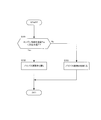
- FIG. 4 is a flowchart showing the flow of the EGR cooler cleaning control.
- FIG. 5A is a schematic view for explaining the state of wrinkles adhering to a tube.
- FIG. 5B is a schematic view illustrating condensed water generated between a tube and a weir.
- FIG. 5C is a schematic view for explaining the state in which the sputum is washed away from the tube.
- FIG. 6 is a flowchart showing a flow of bypass on-off valve on-off control according to the second embodiment of the present invention.
- FIG. 7 is a graph showing the relationship between the engine coolant temperature and the frictional resistance at the time of driving the
- FIG. 1 is a block diagram of an intake / exhaust system of an engine 20 of a diesel vehicle provided with an EGR device 100 according to a first embodiment of the present invention.
- the air supply and exhaust system of the engine 20 includes an intake system 10 connected upstream of the engine 20 and an exhaust system 30 connected downstream.
- An intake system 10 includes an air cleaner 11, a compressor wheel 42 of a turbocharger 40, an intake shutter valve 14, an intercooler 12, and an intake passage connected so that intake air obtained by intake these from the outside can flow And 13.
- the exhaust system 30 includes a turbine wheel 41 of the turbocharger 40, an exhaust purification device 31, and a silencer 32, and an exhaust flow path 33 that connects these so that exhaust gas discharged from the engine 20 can flow. It consists of
- the intake air is supercharged by the compressor wheel 42 of the supercharger 40 after the foreign matter such as dust and dirt is removed by the air cleaner 11 when flowing through the intake flow path 13 and is guided to the intake shutter valve 14. It is eaten.
- the supercharged intake air changes the flow rate according to the opening degree of the intake shutter valve 14, passes through the intake shutter valve 14, is cooled by the intercooler 12, and then passes through the intake manifold (not shown) to the engine 20.
- Led to The intercooler 12 is, for example, water-cooled, and is connected to a sub radiator (not shown) to release the heat taken from the supercharged intake air to the outside.
- the intercooler 12 may be air-cooled.
- the intake air led to the engine 20 is supplied to the combustion chamber 22 through the suction port 21 and is combusted by being compressed together with the fuel injected in the combustion chamber 22.
- the combustion provides the driving force necessary for the diesel vehicle to travel.
- Exhaust gas generated by the combustion is discharged from the exhaust port 23 through an exhaust manifold (not shown) of the exhaust system 30 to the exhaust flow passage 33.
- the exhaust gas passes through the turbine wheel 41 of the turbocharger 40 and is then purified by a diesel oxidation catalyst or a particulate collection filter (not shown) in the exhaust gas purification device 31, and then flows to the silencer 32.
- the exhaust gas that has flowed to the silencer 32 has its pressure and temperature reduced, and its exhaust noise is reduced and discharged to the outside.
- the diesel oxidation catalyst of the exhaust gas purification device 31 is a catalyst that activates and burns the unburned gas in the exhaust gas
- the particulate collection filter is a filter that collects particulates in the exhaust gas. It should be noted that NOx in exhaust gas can be obtained by attaching to the exhaust purification device 31 a NOx reduction catalyst for removing nitrogen oxides and a fuel reforming catalyst that generates a reducing agent used in the NOx reduction catalyst. May be reduced.
- the supercharger 40 for example, a variable displacement turbocharger that controls the flow rate of the exhaust gas or the intake air according to the rotation speed of the engine 20 is used.
- the turbine wheel 41 of the supercharger 40 is rotated by the pressure of the exhaust gas, the rotational force is transmitted to the compressor wheel 42 through the shaft 43 to supercharge the intake air.
- the shaft 43 can introduce a large amount of intake air.
- An EGR device 100 for performing EGR is connected between the exhaust passage 33 and the intake passage 13. By performing EGR by the EGR device 100, it is possible to realize reduction of NOx and improvement of fuel consumption. Further, since the EGR device 100 reduces the exhaust gas upstream of the turbine wheel 41 and the exhaust gas purification device 31, the amount of soot and the like adhering to the turbine wheel 41 and the exhaust gas purification device 31 is reduced to improve the durability. Can.
- the EGR device 100 includes an EGR flow passage 60 and a hot bypass flow passage 70.
- the EGR passage 60 and the hot bypass passage 70 are connected in parallel between the exhaust passage 33 and the intake passage 13, and the exhaust gas recirculated from the exhaust passage 33 circulates inside.
- the EGR flow passage 60 is configured of an EGR inlet side pipe 61 and an EGR outlet side pipe 62.
- An EGR cooler 50 is installed between the EGR inlet side pipe 61 and the EGR outlet side pipe 62.
- the EGR inlet side pipe 61 connects the exhaust flow path 33 and the inlet side connection portion 51 of the EGR cooler 50.
- the EGR outlet side pipe 62 connects the outlet side connecting portion 52 of the EGR cooler 50 and the intake flow path 13.
- the EGR inlet side pipe 61 is formed shorter than the EGR outlet side pipe 62.
- an EGR on-off valve 63 is installed in the EGR outlet-side pipe 62 of the EGR flow passage 60. Therefore, the EGR cooler 50 and the EGR on-off valve 63 are provided in series in the EGR passage 60.
- the hot bypass flow passage 70 is a flow passage for recirculating the exhaust gas of the exhaust flow passage 33 to the intake flow passage 13 without the intervention of the EGR cooler 50 installed in the EGR flow passage 60.
- a hot bypass on-off valve 71 is installed in the hot bypass flow passage 70.
- the hot bypass on-off valve 71 is an on / off valve that switches the flow of exhaust gas passing through the hot bypass passage 70 by being controlled to two positions of full open and full close.
- FIG. 2 is a configuration diagram in which the vicinity of the EGR cooler 50 of the EGR device 100 is enlarged.
- the EGR cooler 50 is a heat exchanger that cools the exhaust gas led from the exhaust flow path 33 by the cooling water flowing inside.
- the EGR on-off valve 63 is a butterfly valve provided on the EGR outlet side pipe 62 and capable of adjusting the flow rate of the exhaust gas recirculated to the intake flow passage 13 according to the opening degree. For example, when the EGR on-off valve 63 is closed, the exhaust gas is not recirculated to the intake passage 13. Thereafter, when the EGR on-off valve 63 is opened, the flow of the exhaust gas is switched, and the exhaust gas is recirculated to the intake flow passage 13 according to the opening degree of the EGR on-off valve 63.
- the EGR inlet side piping 61 of the EGR flow passage 60 is routed in a U-shape from the exhaust flow passage 33 and connected to the EGR cooler 50.
- An exhaust flow path connection portion 61 a is formed in a portion of the EGR inlet side pipe 61 connected to the exhaust flow path 33.
- the exhaust flow passage connecting portion 61a has an introduction port 61b for introducing the exhaust gas of the exhaust flow passage 33 into the EGR inlet side pipe 61, and from the exhaust flow passage 33 from the upstream toward the downstream along the flow direction of the exhaust gas. Branch at a sharp angle ⁇ . Further, the introduction port 61 b is disposed such that a part thereof enters the exhaust flow path 33, and opens toward the flow direction upstream of the exhaust gas of the exhaust flow path 33. Since the ram pressure is generated by forming the exhaust flow path connection portion 61 a in this manner, a part of the exhaust gas flowing through the exhaust flow path 33 can easily flow to the EGR inlet side pipe 61 efficiently. The exhaust gas introduced into the EGR inlet side pipe 61 is guided to the EGR cooler 50.
- the EGR cooler 50 cools the exhaust gas led from the exhaust flow path 33 by the cooling water flowing inside.
- the cooling water is connected so as to be able to cool the engine 20 by a flow path not shown, and releases the heat of the EGR cooler 50 and the engine 20 from the radiator not shown.
- the cooling water can cool not only the engine 20 but also various devices that generate heat of the diesel vehicle.
- a bypass flow passage 64 for leading the exhaust gas having passed through the EGR cooler 50 to the exhaust flow passage 33 is connected to the outlet-side connection portion 52 of the EGR cooler 50.
- the bypass flow passage 64 is a flow passage that guides the exhaust gas that has passed through the EGR cooler 50 to the exhaust flow passage 33.
- a bypass on-off valve 65 is installed in the bypass flow path 64.
- the bypass on-off valve 65 is an on / off valve that switches the flow of exhaust gas passing through the bypass passage 64 by being controlled to two positions of full open and full close.
- FIG. 3 is an internal sectional view of the EGR cooler 50. As shown in FIG.
- the EGR cooler 50 is cooled so as to exchange heat between the EGR gas passage 53 through which the exhaust gas led from the exhaust flow passage 33 flows and the exhaust gas in the EGR gas passage 53. And a plurality of tubes 54 through which the water flows.
- the EGR gas passages 53 are respectively formed between the tubes 54 and the other adjacent tubes 54 by alternately laminating a plurality of tubes 54 at intervals.
- fins (not shown) are disposed in order to enhance the heat exchange efficiency with the exhaust gas.
- the exhaust gas led from the exhaust flow passage 33 flows through the EGR inlet side pipe 61 and the EGR gas passage 53 as shown by an arrow A in FIG.
- bypass on-off valve 65 when the bypass on-off valve 65 is open, the exhaust gas flows to the exhaust flow path 33 through the bypass flow path 64 as shown by arrow C in FIG.
- the bypass passage 64 is connected so as to be directed to the upstream side of the exhaust gas from a part of the wall surface of the outlet side connection portion 52 of the EGR cooler 50 where the throttle is provided. Therefore, the ram pressure acts on the exhaust gas flowing to the bypass passage 64.
- Cooling water flows into the plurality of tubes 54 from the cooling water channel inlet 55 as shown by the arrow D in FIG.
- the cooling water exchanges heat with the exhaust gas passing through the adjacent EGR gas passage 53 through the tube 54 when flowing through the inside of the tube 54, and then the cooling water flow path outlet as shown by an arrow E in FIG. It leaks from 56.
- an EGR cooler outlet water temperature sensor 81 is attached to the cooling water flow path outlet 56.
- the EGR cooler outlet water temperature sensor 81 detects the outlet temperature of the cooling water of the EGR cooler 50 as the engine cooling water temperature Tw.
- an EGR cooler outlet gas temperature sensor 82 that detects the temperature of the exhaust gas that has passed through the EGR cooler 50 may be installed downstream of the EGR gas passage 53 of the EGR cooler 50.
- the controller 80 includes a central processing unit (CPU), a read only memory (ROM), a random access memory (RAM), and the like, and reads the program stored in the ROM by the CPU.
- the engine 20 and the EGR device 100 perform various functions.
- a signal from the EGR cooler outlet water temperature sensor 81 is input to the controller 80 in order to cause the EGR device 100 to exhibit various functions, for example.
- the controller 80 receives signals from the EGR cooler outlet gas temperature sensor 82, an engine rotation sensor (not shown) for detecting the rotational speed of the engine 20, or an accelerator opening detection sensor (not shown) for detecting the accelerator opening. It is also good.
- the controller 80 executes control of the EGR device 100 based on the input signal. That is, the controller 80 controls the opening and closing of the intake shutter valve 14, the EGR on-off valve 63, the hot bypass on-off valve 71, and the bypass on-off valve 65 as shown by the broken line in FIG. Run.
- EGR cooler cleaning control executed by the controller 80 to remove the soot C attached to the EGR cooler 50 will be described with reference to FIGS. 4 to 5C.
- FIG. 4 is a flowchart showing the flow of the EGR cooler cleaning control.
- FIG. 5A is a schematic view illustrating the state of the crucible C attached to the tube 54.
- FIG. 5B is a schematic view illustrating the condensed water W generated between the tube 54 and the weir C.
- FIG. 5C is a schematic view for explaining a state in which the weir C is washed away from the tube 54.
- the controller 80 executes EGR cooler cleaning control together with the EGR control when the engine 20 is cold started.
- the hot bypass on-off valve 71 is opened, the exhaust gas flowing through the exhaust flow passage 33 is not cooled via the hot bypass flow passage 70 by execution of the EGR control. It is refluxed to 13.
- the EGR on-off valve 63 is opened, the exhaust gas is cooled by the EGR cooler 50 when flowing through the EGR gas passage 53 and is recirculated to the intake flow passage 13.
- the cold start is to start the engine 20 when the engine 20 and the like cool to near the outside temperature, for example, a situation where the engine 20 is started after the diesel vehicle is parked overnight is a cold start is assumed. Therefore, the engine coolant temperature Tw is also cooled to about the outside air temperature. As shown in FIG. 5A, soot C deposited by traveling of the diesel vehicle up to the previous time is deposited on the surface of the tube 54 of the EGR cooler 50 at the cold start.
- step S101 the controller 80 determines whether the engine coolant temperature Tw is less than a predetermined temperature T.
- the process of the controller 80 proceeds to step S102, and when the engine cooling water temperature Tw is higher than the predetermined temperature T (first predetermined temperature), the process proceeds to step S103.
- the predetermined temperature T is a lower limit temperature at which the exhaust gas can not be cooled to the dew point temperature Td or less when the exhaust gas is cooled, and is 55 ° C., for example.
- condensed water W is generated between the tube 54 and the crucible C as shown in FIG. 5B.
- the condensed water W is the condensation of water vapor contained in the exhaust gas as the exhaust gas that has entered the interior of the crucible C from the fine gaps on the surface of the crucible C is cooled near the surface of the tube 54. Further, the condensed water W is also generated by cooling the exhaust gas existing in advance in the crucible C deposited near the surface of the tube 54 and condensing water vapor in the exhaust gas.
- the ⁇ C is one obtained by coalescing and solidifying hydrocarbons remaining in the combustion process through various chemical reactions, and has an oily (hydrophobic) property. Therefore, the generated condensed water W forms a water film layer by spreading between the tube 54 and the crucible C without being absorbed by the hydrophobic crucible C. As a result, the weir C is forced to be separated from the surface of the tube 54 by the water film.
- step S102 the controller 80 opens the bypass on-off valve 65.
- Cleaning of the EGR cooler 50 is executed by opening the bypass on-off valve 65, and exhaust gas having passed through the EGR cooler 50 vigorously passes through the bypass flow path 64. Therefore, as shown in FIG. 5C, the soot C separated from the surface of the tube 54 and blown off downstream together with the condensed water W by the exhaust gas flows through the bypass flow path 64 as shown by the arrow C in FIG. It flows to the road 33.
- step S103 the controller 80 closes the bypass on-off valve 65.
- the previous EGR control is restarted. Therefore, when the hot bypass on-off valve 71 is opened before execution of the EGR cooler cleaning control, the hot bypass on-off valve 71 is opened again, and the bypass on-off valve 65 is opened before execution of the EGR cooler cleaning control.
- the bypass on-off valve 65 is reopened. At that time, since the temperature of the exhaust gas when the engine coolant temperature Tw exceeds the predetermined temperature T is usually high temperature of 100 ° C. or higher, the blown-off condensed water W evaporates when blown away. The liquid does not flow to the engine 20 as it is.
- the bypass on-off valve 65 is controlled by giving priority to the EGR on-off valve 63.
- the invention is not limited to this, and the EGR on-off valve 63 may be prioritized.
- the bypass on-off valve 65 may be controlled.
- the priority is given to the EGR on-off valve 63 to reduce NOx (nitrogen oxide) due to exhaust gas and to improve the fuel consumption performance, and further detects the on-off state of the EGR on-off valve 63 to bypass the on-off valve
- NOx nitrogen oxide
- the soot C is forced from the surface of the tube 54 by the water film. Since the soot C can be washed out as it is by the momentum of the exhaust gas, it is possible to prevent the reduction of the heat exchange efficiency.
- the EGR device 100 causes part of the exhaust gas discharged from the engine 20 to recirculate from the exhaust passage 33 to the intake passage 13.
- the EGR device 100 includes an EGR cooler 50 that cools the exhaust gas led from the exhaust flow passage 33 with cooling water as a refrigerant flowing inside, and a bypass that guides the exhaust gas that has passed through the EGR cooler 50 to the exhaust flow passage 33
- a flow path 64 and a bypass on-off valve 65 provided in the bypass flow path 64 to switch the flow of exhaust gas passing through the bypass flow path 64 are provided.
- the bypass on-off valve 65 is opened when the engine coolant temperature Tw, which is the temperature of the refrigerant flowing through the inside of the EGR cooler 50, is equal to or lower than a predetermined temperature T (first predetermined temperature).
- the bypass on-off valve 65 is opened, whereby the exhaust gas passing through the EGR cooler 50 is conducted to the bypass passage 64.
- the EGR cooler 50 it is cooled to below the dew point temperature Td. Therefore, a water film of the condensed water W is formed between the surface of the tube 54 of the EGR cooler 50 and the adhered soot C, and the tube 54 and the soot C are separated by the water film.
- the EGR device 100 is provided in an EGR outlet side pipe 62 connecting the EGR cooler 50 and the intake flow path 13 and an EGR outlet side pipe 62, and switches the flow of the exhaust gas to be recirculated to the intake flow path 13 And further comprising
- the EGR on-off valve 63 is closed when the engine coolant temperature Tw, which is the temperature of the refrigerant flowing through the inside of the EGR cooler 50, is equal to or lower than a predetermined temperature T.
- the temperature of the exhaust gas may not have reached a high temperature of 100 ° C. or higher. Is closed. Therefore, the blown-off condensed water W can be reliably prevented from flowing to the engine 20 as a liquid.
- the EGR device 100 further includes an EGR inlet side pipe 61 connecting the exhaust flow passage 33 and the EGR cooler 50.
- the EGR inlet side pipe 61 has an exhaust flow path connection portion 61 a connected to the exhaust flow path 33.
- the exhaust passage connection portion 61 a branches from the upstream toward the downstream along the flow direction of the exhaust gas of the exhaust passage 33 at an acute angle ⁇ .
- the exhaust gas of the exhaust flow passage 33 receives ram pressure at the exhaust flow passage connecting portion 61a when it flows downstream. Therefore, a part of the exhaust gas of the exhaust flow path 33 can be efficiently flowed into the EGR inlet side pipe 61.
- the exhaust passage connection portion 61a has an introduction port 61b formed in the exhaust passage 33.
- the inlet 61 b opens toward the upstream in the flow direction of the exhaust gas of the exhaust flow passage 33.
- the exhaust passage connection portion 61a may be branched from the exhaust passage 33 at an acute angle ⁇ so that the ram pressure acts, and is disposed so that the entire inlet 61b does not enter the exhaust passage 33. May be As a result, the exhaust gas can be efficiently flowed into the EGR cooler 50 by the ram pressure while suppressing an increase in the pressure loss of the exhaust passage 33.
- the exhaust flow path connection portion 61a is disposed such that a part of the introduction port 61b enters the exhaust flow path 33, but the entire introduction port 61b enters the exhaust flow path 33. It may be arranged to face the upstream of the exhaust flow path 33.
- the bypass flow passage 64 is connected to the downstream side in the flow direction of the exhaust gas of the exhaust flow passage 33 than the exhaust flow passage connecting portion 61a. Therefore, the exhaust gas having passed through the EGR cooler 50 flows through the bypass flow path 64 to the exhaust flow path 33, so the soot C separated from the surface of the tube 54 is also discharged to the exhaust flow path 33 by the flow of the exhaust gas. can do.
- the EGR cooler 50 circulates the exhaust gas led from the exhaust flow path 33 so that heat exchange is performed between the refrigerant flowing inside and the exhaust gas led from the exhaust flow path 33
- the EGR gas passage 53 is provided.
- the bypass flow passage 64 is provided at the outlet side connection portion 52 of the EGR cooler 50 so as to lead the exhaust gas having passed through the EGR gas passage 53 to the exhaust flow passage 33. Therefore, the soot C separated from the surface of the tube 54 can be discharged to the exhaust flow passage 33 by the force of the exhaust gas having passed through the EGR cooler 50 flowing through the bypass flow passage 64 into the exhaust flow passage 33.
- the bypass passage 64 may be provided in the EGR outlet side pipe 62 so as to guide the exhaust gas having passed through the EGR cooler 50 to the exhaust passage 33.
- Such an EGR device 100 includes an EGR outlet-side pipe 62 that connects the EGR cooler 50 and the intake flow path 13.
- the bypass flow passage 64 is provided in the EGR outlet side pipe 62 so as to lead the exhaust gas that has passed through the EGR cooler 50 to the exhaust flow passage 33. Therefore, the soot C separated from the surface of the tube 54 can be discharged to the exhaust flow path 33 as in the EGR cooler 50 of the first embodiment described above.
- FIG. 6 is a flowchart showing a flow of bypass on-off valve on-off control according to the second embodiment.
- the on-off conditions of the bypass on-off valve are different from the EGR cooler cleaning control of the first embodiment.
- the same reference numerals are used for the configurations that perform the same functions as those of the first embodiment, and redundant descriptions will be appropriately omitted.
- the controller 80 executes bypass on-off valve on-off control together with EGR control when the engine 20 is cold-started.
- the hot bypass on-off valve 71 is opened, the exhaust gas flowing through the exhaust flow passage 33 is not cooled via the hot bypass flow passage 70 by execution of the EGR control. To reflux.
- the EGR on-off valve 63 is open, the exhaust gas is cooled by the EGR cooler 50 when flowing through the EGR gas passage 53 and is recirculated to the intake flow passage 13.
- the cold start is to start the engine 20 when the engine 20 and the like cool to near the outside temperature, for example, a situation where the engine 20 is started after the diesel vehicle is parked overnight is a cold start is assumed. Therefore, the engine coolant temperature Tw is also cooled to about the outside air temperature. As shown in FIG. 5A, soot C deposited by traveling of the diesel vehicle up to the previous time is deposited on the surface of the tube 54 of the EGR cooler 50 at the cold start.
- step S201 the controller 80 determines whether the engine coolant temperature Tw is less than the dew point temperature Td.
- the process of the controller 80 proceeds to step S202 when the engine coolant temperature Tw is less than the dew point temperature Td, and proceeds to step S203 when the temperature is equal to or higher than the dew point temperature Td.
- the dew point temperature Td is a temperature at which the water contained in the exhaust gas condenses to generate the condensed water W when the exhaust gas is cooled, and is 60 ° C., for example.
- condensed water W is generated between the tube 54 and the crucible C as shown in FIG. 5B.
- the condensed water W is the condensation of water vapor contained in the exhaust gas as the exhaust gas that has entered the interior of the crucible C from the fine gaps on the surface of the crucible C is cooled near the surface of the tube 54. Further, the condensed water W is also generated by cooling the exhaust gas existing in advance in the crucible C deposited near the surface of the tube 54 and condensing water vapor in the exhaust gas.
- the ⁇ C is one obtained by coalescing and solidifying hydrocarbons remaining in the combustion process through various chemical reactions, and has an oily (hydrophobic) property. Therefore, the generated condensed water W forms a water film layer by spreading between the tube 54 and the crucible C without being absorbed by the hydrophobic crucible C. As a result, the weir C is forced to be separated from the surface of the tube 54 by the water film.
- step S202 the controller 80 opens the bypass on-off valve 65.
- Cleaning of the EGR cooler 50 is executed by opening the bypass on-off valve 65, and exhaust gas having passed through the EGR cooler 50 vigorously passes through the bypass flow path 64. Therefore, as shown in FIG. 5C, the soot C separated from the surface of the tube 54 and blown off downstream together with the condensed water W by the exhaust gas flows through the bypass flow path 64 as shown by the arrow C in FIG. It flows to the road 33.
- step S203 the controller 80 determines whether the engine coolant temperature Tw is less than a predetermined temperature Tw1.
- the process of the controller 80 proceeds to step S204 when the engine coolant temperature Tw is less than the predetermined temperature Tw1, and proceeds to step S206 when the temperature is equal to or higher than the predetermined temperature Tw1 (second predetermined temperature).
- the predetermined temperature Tw1 is a target warm-up temperature of the engine 20.
- the predetermined temperature Tw1 is a temperature at which the frictional resistance Rf at the time of driving the engine 20 is reduced, and is, for example, 80.degree. Therefore, the predetermined temperature Tw1 is higher than the dew point temperature Td and the predetermined temperature T (first predetermined temperature).
- the relationship between the engine coolant temperature Tw and the frictional resistance Rf will be described with reference to FIG.
- FIG. 7 is a graph showing the relationship between the engine coolant temperature Tw and the frictional resistance Rf when the engine 20 is driven.
- the frictional resistance Rf is a resistance generated by friction when a cylinder, a piston or the like in the engine 20 is driven.
- the frictional resistance Rf becomes smaller as shown in FIG. 7 as the engine coolant temperature Tw, which has a correlation with the viscosity of the oil lubricating the inside of the engine 20, becomes higher.
- the frictional resistance Rf is high, the mechanical loss of the engine 20 becomes large, but for example, when the engine coolant temperature Tw becomes higher than the predetermined temperature Tw1, the frictional resistance Rf can be made equal to or lower than the allowable frictional resistance Rf1. The mechanical loss of the engine 20 can be reduced.
- step S204 the controller 80 determines whether the EGR on-off valve 63 is in a closed state. The process of the controller 80 proceeds to step S205 if the EGR on / off valve 63 is in the closed state, and proceeds to step S206 if it is not in the closed state, that is, if it is in the open state.
- step S205 the controller 80 opens the bypass on-off valve 65.
- the bypass on-off valve 65 When the bypass on-off valve 65 is opened, a part of the exhaust gas flowing through the exhaust flow path 33 flows into the EGR cooler 50 and flows through the bypass flow path 64 to the downstream exhaust flow path 33. Therefore, the cooling water in the EGR cooler 50 exchanges heat with the exhaust gas to recover the heat of the exhaust gas.
- step S206 the controller 80 closes the bypass on-off valve 65.
- the bypass on-off valve 71 is closed in the process of S206. Further, even when the EGR on-off valve 63 is in the open state, that is, the EGR is being executed so that the exhaust gas passes through the EGR cooler 50, the bypass on-off valve 71 is closed in the process of step S206. It does not affect EGR.
- the condensed water W since the temperature of the exhaust gas when the engine coolant temperature Tw is equal to or higher than the predetermined temperature Tw1 is high temperature, even if the condensed water W is accumulated in the EGR cooler 50, the condensed water W is blown away When it evaporates. Therefore, the condensed water W does not flow to the engine 20 as a liquid.
- the hot bypass on-off valve 71 may be opened in parallel with the bypass on-off valve on-off control described above. Even in such a mode, part of the exhaust gas flowing to the downstream side of the exhaust flow passage 33 without passing through the hot bypass flow passage 70 can be flowed into the EGR cooler 50 by opening the bypass on-off valve 65 Thus, the heat of the exhaust gas can be recovered by the cooling water in the EGR cooler 50.
- the bypass on-off valve 65 is controlled by giving priority to the EGR on-off valve 63, but the invention is not limited to this.
- the bypass on-off valve 65 may be controlled.
- the priority is given to the EGR on-off valve 63 to reduce NOx (nitrogen oxide) due to exhaust gas and to improve the fuel consumption performance, and further detects the on-off state of the EGR on-off valve 63 to bypass the on-off valve
- NOx nitrogen oxide
- the soot C is forced from the surface of the tube 54 by the water film. Since the soot C can be washed out as it is by the momentum of the exhaust gas, it is possible to prevent the reduction of the heat exchange efficiency.
- the EGR device 100 causes part of the exhaust gas discharged from the engine 20 to recirculate from the exhaust passage 33 to the intake passage 13.
- the EGR device 100 includes an EGR cooler 50 that cools the exhaust gas led from the exhaust flow passage 33 with cooling water as a refrigerant flowing inside, and a bypass that guides the exhaust gas that has passed through the EGR cooler 50 to the exhaust flow passage 33
- a flow path 64 and a bypass on-off valve 65 provided in the bypass flow path 64 to switch the flow of exhaust gas passing through the bypass flow path 64 are provided.
- the bypass on-off valve 65 has a predetermined temperature Tw1 (second predetermined temperature) at which the engine cooling water temperature Tw, which is the temperature of the cooling water flowing through the inside of the EGR cooler 50, is higher than the predetermined temperature T (first predetermined temperature).
- Tw1 second predetermined temperature
- Tw1 first predetermined temperature
- the bypass is made when the engine coolant temperature Tw is lower than the predetermined temperature Tw1 and the exhaust gas having passed through the EGR cooler 50 is not recirculated from the exhaust passage 33 to the intake passage 13
- the on-off valve 65 By opening the on-off valve 65, the exhaust gas that has passed through the EGR cooler 50 is guided to the bypass flow passage 64.
- the exhaust gas led to the bypass flow passage 64 exchanges heat with the cooling water in the EGR cooler 50. Therefore, the cooling water in the EGR cooler 50 can efficiently recover, for example, the heat for warming the engine 20 from the exhaust gas as another device that needs to be warmed up.
- bypass on-off valve 65 is opened when the exhaust gas having passed through the EGR cooler 50 is not recirculated from the exhaust flow path 33 to the intake flow path 13, the exhaust gas flows to the bypass flow path 64 to generate EGR. There is no effect.
- the predetermined temperature Tw1 is a target warm-up temperature of the engine 20.
- the target warm-up temperature of the engine 20 is, for example, a temperature at which the frictional resistance Rf at the time of driving the engine 20 is reduced to the allowable frictional resistance Rf1 or less.
- the predetermined temperature Tw1 is a temperature higher than the dew point temperature Td at which the condensed water W is generated in the EGR cooler 50. Therefore, the engine cooling water temperature Tw is lower than the predetermined temperature Tw1, and when the frictional resistance Rf at the time of driving the engine 20 is large, the engine 20 can be warmed using the heat of the exhaust gas. As a result, the engine 20 can be efficiently warmed, and mechanical loss of the engine 20 can be reduced.
- the bypass on-off valve 65 is closed when the engine coolant temperature Tw, which is the temperature of the coolant flowing through the inside of the EGR cooler 50, is equal to or higher than a predetermined temperature Tw1. Therefore, after the warm-up of the engine 20 is completed, the exhaust gas does not flow in the bypass flow passage 64. Therefore, the EGR can be performed to reduce NOx and improve the fuel consumption.
- the bypass on-off valve 65 is closed when the exhaust gas that has passed through the EGR cooler 50 is recirculated from the exhaust passage 33 to the intake passage 13. Therefore, when the controller 80 is performing EGR so that the exhaust gas passes through the EGR cooler 50, the bypass on-off valve 65 is closed. The influence can be avoided.
- the EGR device 100 is provided in an EGR outlet side pipe 62 connecting the EGR cooler 50 and the intake flow path 13 and an EGR outlet side pipe 62, and switches the flow of the exhaust gas to be recirculated to the intake flow path 13 And further comprising
- the EGR on-off valve 63 is closed when the engine coolant temperature Tw, which is the temperature of the coolant flowing through the inside of the EGR cooler 50, is equal to or lower than a predetermined temperature Tw1.
- the engine coolant temperature Tw when the engine coolant temperature Tw is equal to or lower than the predetermined temperature Tw1, the temperature of the exhaust gas may not be high, so the EGR on-off valve 63 is closed. Therefore, the blown-off condensed water W can be reliably prevented from flowing to the engine 20 as a liquid.
- the EGR device 100 further includes an EGR inlet side pipe 61 connecting the exhaust flow passage 33 and the EGR cooler 50.
- the EGR inlet side pipe 61 has an exhaust flow path connection portion 61 a connected to the exhaust flow path 33.
- the exhaust passage connection portion 61 a branches from the upstream toward the downstream along the flow direction of the exhaust gas of the exhaust passage 33 at an acute angle ⁇ .
- the exhaust gas of the exhaust flow passage 33 receives ram pressure at the exhaust flow passage connecting portion 61a when it flows downstream. Therefore, a part of the exhaust gas of the exhaust flow path 33 can be efficiently flowed into the EGR inlet side pipe 61.
- the exhaust passage connection portion 61a has an introduction port 61b formed in the exhaust passage 33.
- the inlet 61 b opens toward the upstream in the flow direction of the exhaust gas of the exhaust flow passage 33.
- the exhaust passage connection portion 61a may be branched from the exhaust passage 33 at an acute angle ⁇ so that the ram pressure acts, and is disposed so that the entire inlet 61b does not enter the exhaust passage 33. May be As a result, the exhaust gas can be efficiently flowed into the EGR cooler 50 by the ram pressure while suppressing an increase in the pressure loss of the exhaust passage 33.
- the exhaust flow path connection portion 61a is disposed such that a part of the introduction port 61b enters the exhaust flow path 33, but the entire introduction port 61b enters the exhaust flow path 33. It may be arranged to face the upstream of the exhaust flow path 33.
- the bypass flow passage 64 is connected to the downstream side in the flow direction of the exhaust gas of the exhaust flow passage 33 than the exhaust flow passage connecting portion 61a. Therefore, the exhaust gas having passed through the EGR cooler 50 flows through the bypass flow path 64 to the exhaust flow path 33, so the soot C separated from the surface of the tube 54 is also discharged to the exhaust flow path 33 by the flow of the exhaust gas. can do.
- the EGR cooler 50 circulates the exhaust gas led from the exhaust flow path 33 so that heat exchange is performed between the refrigerant flowing inside and the exhaust gas led from the exhaust flow path 33
- the EGR gas passage 53 is provided.
- the bypass flow passage 64 is provided at the outlet side connection portion 52 of the EGR cooler 50 so as to lead the exhaust gas having passed through the EGR gas passage 53 to the exhaust flow passage 33. Therefore, the soot C separated from the surface of the tube 54 can be discharged to the exhaust flow passage 33 by the force of the exhaust gas having passed through the EGR cooler 50 flowing through the bypass flow passage 64 into the exhaust flow passage 33.
- the bypass passage 64 may be provided in the EGR outlet side pipe 62 so as to guide the exhaust gas having passed through the EGR cooler 50 to the exhaust passage 33.
- Such an EGR device 100 includes an EGR outlet-side pipe 62 that connects the EGR cooler 50 and the intake flow path 13.
- the bypass flow passage 64 is provided in the EGR outlet side pipe 62 so as to lead the exhaust gas that has passed through the EGR cooler 50 to the exhaust flow passage 33. Therefore, the soot C separated from the surface of the tube 54 can be discharged to the exhaust flow path 33 as in the EGR cooler 50 of the second embodiment described above.
- the heat recovered from the exhaust gas may be used not only for warming up the engine 20 but also for warming up a transmission (not shown) and heating the vehicle interior.
- the EGR device 100 is installed so as to connect the upstream side of the compressor wheel 42 of the intake flow passage 13 and the downstream side of the exhaust gas purification device 31 of the exhaust flow passage 33 without limiting to the aspect of the above embodiment. It may be By this, the same effect as that of the above embodiment can be obtained.
- the EGR device 100 may be applied not only to diesel vehicles but also to gasoline vehicles.
Abstract
An EGR device (100) that returns a portion of the exhaust gas discharged from an engine (20) from an exhaust flow path (33) to an intake flow path (13). The EGR device (100) is equipped with: an EGR cooler (50) that, by means of cooling water flowing as a coolant through the interior of the EGR cooler, cools the exhaust gas guided from the exhaust flow path (33); a bypass flow path (64) that guides the exhaust gas that has passed through the EGR cooler (50) to the exhaust flow path (33); and a bypass opening/closing valve (65) that is provided in the bypass flow path (64), and switches the flow of the exhaust gas passing through the bypass flow path (64). The bypass opening/closing valve (65) is opened when the engine cooling water temperature Tw, which is the temperature of the coolant flowing through the interior of the EGR cooler (50), is equal to or less than a prescribed temperature T.
Description
本発明は、EGR(Exhaust Gas Recirculation:排気再循環)装置に関する。
The present invention relates to an EGR (Exhaust Gas Recirculation) device.
JP2010-048113Aには、高温のガスが流れているときにEGRクーラの入口に水を噴射して蒸発させ、チューブの表面に付着した煤を水蒸気で洗い流すことによって、煤堆積による熱交換効率の低下を防止するEGR装置が開示されている。
In JP2010-048113A, when high-temperature gas is flowing, water is injected to evaporate at the inlet of the EGR cooler to evaporate it, and the soot adhering to the surface of the tube is washed away with steam to reduce the heat exchange efficiency due to soot accumulation. Discloses an EGR device for preventing the
しかしながら、JP2010-048113AのEGR装置では、水蒸気はガスとともにEGRクーラのチューブ内を流れるので、付着した煤は表面側から洗浄される。そのため、煤表面のごく一部しか洗い流すことができず、チューブに付着した煤の多くがそのまま表面に留まって固着し堆積して熱交換効率が低下するおそれがある。
However, in the EGR device of JP2010-048113A, the water vapor flows in the tube of the EGR cooler together with the gas, so the adhering soot is cleaned from the surface side. Therefore, only a very small part of the surface of the crucible can be washed away, and most of the crucible attached to the tube may remain on the surface as it is and adhere to it, causing the heat exchange efficiency to decrease.
本発明は、チューブの表面に付着した煤を洗い流すことができ、熱交換効率の低下を防止できるEGR装置を提供することを目的とする。
An object of the present invention is to provide an EGR device which can wash out dirt adhering to the surface of a tube and can prevent a decrease in heat exchange efficiency.
本発明のある態様によれば、エンジンから排出された排気ガスの一部を排気流路から吸気流路に還流させるEGR装置は、前記排気流路から導かれた排気ガスを、内部を流通する冷媒によって冷却するEGRクーラと、前記EGRクーラを通過した排気ガスを前記排気流路に導くバイパス流路と、前記バイパス流路に設けられ、前記バイパス流路を通過する排気ガスの流れを切り替えるバイパス開閉弁と、を備え、前記バイパス開閉弁は、前記EGRクーラの内部を流通する冷媒の温度が第1の所定温度以下である場合に開かれる。
According to an aspect of the present invention, an EGR device for recirculating a part of exhaust gas discharged from an engine from an exhaust flow path to an intake flow path circulates the exhaust gas led from the exhaust flow path inside. An EGR cooler that is cooled by a refrigerant, a bypass flow path that guides exhaust gas that has passed through the EGR cooler to the exhaust flow path, and a bypass that is provided in the bypass flow path and switches the flow of exhaust gas that passes through the bypass flow path An on-off valve is opened, and the bypass on-off valve is opened when the temperature of the refrigerant flowing through the inside of the EGR cooler is equal to or lower than a first predetermined temperature.
上記態様によれば、EGRクーラの内部を流通する冷媒の温度が第1の所定温度以下である場合にバイパス開閉弁が開かれることで、EGRクーラを通過した排気ガスがバイパス流路へと導かれる際に、EGRクーラ内で露点温度を下回るまで冷却される。そのため、EGRクーラのチューブの表面と付着した煤との間に凝縮水による水膜が形成され、水膜によってチューブと煤とが分離された状態になるので、EGRクーラ内を流れる排気ガスの勢いによって、チューブの表面から分離された煤をそのまま洗い流すことができる。また、前回走行時に付着した煤をコールドスタート時に毎回洗い流すことができるので、時間経過とともに煤がチューブの表面で固着することも抑制できる。よって、熱交換効率の低下を防止できるEGR装置を提供することができる。
According to the above aspect, when the temperature of the refrigerant flowing through the inside of the EGR cooler is equal to or lower than the first predetermined temperature, the bypass on-off valve is opened, whereby the exhaust gas passing through the EGR cooler is conducted to the bypass flow passage. As it cools, it cools to below the dew point temperature in the EGR cooler. Therefore, a water film of condensed water is formed between the surface of the tube of the EGR cooler and the adhered soot, and the tube and the soot are separated by the water film, so the momentum of the exhaust gas flowing in the EGR cooler Allows the sputum separated from the surface of the tube to be washed away as it is. In addition, since it is possible to wash away soot that has adhered during the previous travel each time cold start, it is also possible to suppress sticking of soot on the surface of the tube with the passage of time. Therefore, it is possible to provide an EGR device capable of preventing a decrease in heat exchange efficiency.
以下、図面を参照して、本発明の実施形態について説明する。
Hereinafter, embodiments of the present invention will be described with reference to the drawings.
(第1実施形態)
図1は本発明の第1実施形態に係るEGR装置100を備えるディーゼル車両のエンジン20の吸排気系の構成図である。 First Embodiment
FIG. 1 is a block diagram of an intake / exhaust system of anengine 20 of a diesel vehicle provided with an EGR device 100 according to a first embodiment of the present invention.
図1は本発明の第1実施形態に係るEGR装置100を備えるディーゼル車両のエンジン20の吸排気系の構成図である。 First Embodiment
FIG. 1 is a block diagram of an intake / exhaust system of an
エンジン20の給排気系は、エンジン20の上流に接続される吸気系10と、下流に接続される排気系30と、を備える。
The air supply and exhaust system of the engine 20 includes an intake system 10 connected upstream of the engine 20 and an exhaust system 30 connected downstream.
吸気系10は、エアクリーナ11と、過給機40のコンプレッサホイール42と、吸気シャッターバルブ14と、インタークーラ12と、これらを外部から吸入した吸入空気が流通可能となるように接続する吸気流路13と、から構成される。
An intake system 10 includes an air cleaner 11, a compressor wheel 42 of a turbocharger 40, an intake shutter valve 14, an intercooler 12, and an intake passage connected so that intake air obtained by intake these from the outside can flow And 13.
排気系30は、過給機40のタービンホイール41と、排気浄化装置31と、サイレンサ32と、これらをエンジン20から排出された排気ガスが流通可能となるように接続する排気流路33と、から構成される。
The exhaust system 30 includes a turbine wheel 41 of the turbocharger 40, an exhaust purification device 31, and a silencer 32, and an exhaust flow path 33 that connects these so that exhaust gas discharged from the engine 20 can flow. It consists of
吸入空気は、吸気流路13を流通する際に、エアクリーナ11によってごみやほこり等の異物が取り除かれた後に、過給機40のコンプレッサホイール42によって過給されて、吸気シャッターバルブ14へと導かれる。過給された吸入空気は、吸気シャッターバルブ14の開度に応じて流量を変化させて吸気シャッターバルブ14を通過して、インタークーラ12で冷却された後に、図示しないインテークマニホールドを通ってエンジン20へ導かれる。インタークーラ12は、例えば水冷式であり、図示しないサブラジエータに接続されて過給された吸入空気から取り込んだ熱を外部に放出する。なお、インタークーラ12には、空冷式を採用してもよい。
The intake air is supercharged by the compressor wheel 42 of the supercharger 40 after the foreign matter such as dust and dirt is removed by the air cleaner 11 when flowing through the intake flow path 13 and is guided to the intake shutter valve 14. It is eaten. The supercharged intake air changes the flow rate according to the opening degree of the intake shutter valve 14, passes through the intake shutter valve 14, is cooled by the intercooler 12, and then passes through the intake manifold (not shown) to the engine 20. Led to The intercooler 12 is, for example, water-cooled, and is connected to a sub radiator (not shown) to release the heat taken from the supercharged intake air to the outside. The intercooler 12 may be air-cooled.
エンジン20に導かれた吸入空気は、吸入ポート21を通って燃焼室22に供給され、燃焼室22内で噴射された燃料とともに圧縮されることで燃焼する。当該燃焼によって、ディーゼル車両が走行するために必要な推進力が得られる。
The intake air led to the engine 20 is supplied to the combustion chamber 22 through the suction port 21 and is combusted by being compressed together with the fuel injected in the combustion chamber 22. The combustion provides the driving force necessary for the diesel vehicle to travel.
燃焼により生成された排気ガスは、排気ポート23から排気系30の図示しないエキゾーストマニホールドを通って排気流路33へと排出される。排気ガスは、過給機40のタービンホイール41を通過してから排気浄化装置31内の図示しないディーゼル酸化触媒や微粒子捕集フィルタによって浄化された後に、サイレンサ32へと流通する。サイレンサ32へ流通した排気ガスは、圧力や温度が低減されるとともに排気騒音が低減されて外部に排出される。排気浄化装置31のディーゼル酸化触媒は、排気ガス中の未燃焼ガスを活性化させ燃焼させる触媒であり、微粒子捕集フィルタは、排気ガス中の微粒子を捕集するフィルタである。なお、排気浄化装置31に、窒素酸化物を除去するためのNOx還元触媒と、NOx還元触媒にて使用される還元剤を生成する燃料改質触媒と、を取り付けることによって、排気ガス中のNOxを還元させてもよい。
Exhaust gas generated by the combustion is discharged from the exhaust port 23 through an exhaust manifold (not shown) of the exhaust system 30 to the exhaust flow passage 33. The exhaust gas passes through the turbine wheel 41 of the turbocharger 40 and is then purified by a diesel oxidation catalyst or a particulate collection filter (not shown) in the exhaust gas purification device 31, and then flows to the silencer 32. The exhaust gas that has flowed to the silencer 32 has its pressure and temperature reduced, and its exhaust noise is reduced and discharged to the outside. The diesel oxidation catalyst of the exhaust gas purification device 31 is a catalyst that activates and burns the unburned gas in the exhaust gas, and the particulate collection filter is a filter that collects particulates in the exhaust gas. It should be noted that NOx in exhaust gas can be obtained by attaching to the exhaust purification device 31 a NOx reduction catalyst for removing nitrogen oxides and a fuel reforming catalyst that generates a reducing agent used in the NOx reduction catalyst. May be reduced.
過給機40には、例えば、エンジン20の回転数に応じて排気ガスや吸入空気の流速を制御する可変容量型のターボチャージャが用いられる。排気ガスの圧力により過給機40のタービンホイール41が回転すると、シャフト43を介してコンプレッサホイール42にその回転力が伝達されて吸入空気を過給するので、自然吸気の場合と比べてエンジン20に大量の吸入空気を導入することができる。
As the supercharger 40, for example, a variable displacement turbocharger that controls the flow rate of the exhaust gas or the intake air according to the rotation speed of the engine 20 is used. When the turbine wheel 41 of the supercharger 40 is rotated by the pressure of the exhaust gas, the rotational force is transmitted to the compressor wheel 42 through the shaft 43 to supercharge the intake air. Can introduce a large amount of intake air.
排気流路33と吸気流路13との間には、EGRを実行するEGR装置100が接続される。EGR装置100がEGRを実行することによって、NOxの低減や燃費向上を実現することができる。また、EGR装置100は、タービンホイール41や排気浄化装置31より上流で排気ガスを還元させるので、タービンホイール41や排気浄化装置31に付着する煤等の量を低減させ、耐久性を向上させることができる。
An EGR device 100 for performing EGR is connected between the exhaust passage 33 and the intake passage 13. By performing EGR by the EGR device 100, it is possible to realize reduction of NOx and improvement of fuel consumption. Further, since the EGR device 100 reduces the exhaust gas upstream of the turbine wheel 41 and the exhaust gas purification device 31, the amount of soot and the like adhering to the turbine wheel 41 and the exhaust gas purification device 31 is reduced to improve the durability. Can.
EGR装置100は、EGR流路60と、ホットバイパス流路70と、を備える。EGR流路60及びホットバイパス流路70は、排気流路33と吸気流路13との間に並列に接続され、排気流路33から還流させた排気ガスが内部を流通する。
The EGR device 100 includes an EGR flow passage 60 and a hot bypass flow passage 70. The EGR passage 60 and the hot bypass passage 70 are connected in parallel between the exhaust passage 33 and the intake passage 13, and the exhaust gas recirculated from the exhaust passage 33 circulates inside.
EGR流路60は、EGR入口側配管61と、EGR出口側配管62と、から構成される。EGR入口側配管61とEGR出口側配管62との間にはEGRクーラ50が設置される。EGR入口側配管61は、排気流路33とEGRクーラ50の入口側接続部51とを接続する。EGR出口側配管62は、EGRクーラ50の出口側接続部52と吸気流路13とを接続する。EGR入口側配管61は、EGR出口側配管62よりも短く形成される。
The EGR flow passage 60 is configured of an EGR inlet side pipe 61 and an EGR outlet side pipe 62. An EGR cooler 50 is installed between the EGR inlet side pipe 61 and the EGR outlet side pipe 62. The EGR inlet side pipe 61 connects the exhaust flow path 33 and the inlet side connection portion 51 of the EGR cooler 50. The EGR outlet side pipe 62 connects the outlet side connecting portion 52 of the EGR cooler 50 and the intake flow path 13. The EGR inlet side pipe 61 is formed shorter than the EGR outlet side pipe 62.
また、EGR流路60のEGR出口側配管62には、EGR開閉弁63が設置される。したがって、EGR流路60には、EGRクーラ50とEGR開閉弁63とが直列に設けられる。
Further, an EGR on-off valve 63 is installed in the EGR outlet-side pipe 62 of the EGR flow passage 60. Therefore, the EGR cooler 50 and the EGR on-off valve 63 are provided in series in the EGR passage 60.
ホットバイパス流路70は、EGR流路60に設置されるEGRクーラ50を介さずに排気流路33の排気ガスを吸気流路13へと還流させる流路である。ホットバイパス流路70には、ホットバイパス開閉弁71が設置される。
The hot bypass flow passage 70 is a flow passage for recirculating the exhaust gas of the exhaust flow passage 33 to the intake flow passage 13 without the intervention of the EGR cooler 50 installed in the EGR flow passage 60. A hot bypass on-off valve 71 is installed in the hot bypass flow passage 70.
ホットバイパス開閉弁71は、全開と全閉との二位置に制御されることによって、ホットバイパス流路70を通過する排気ガスの流れを切り替えるオン・オフバルブである。
The hot bypass on-off valve 71 is an on / off valve that switches the flow of exhaust gas passing through the hot bypass passage 70 by being controlled to two positions of full open and full close.
ここで、図2を参照して、EGR装置100について説明する。図2は、EGR装置100のEGRクーラ50付近を拡大した構成図である。
Here, the EGR device 100 will be described with reference to FIG. FIG. 2 is a configuration diagram in which the vicinity of the EGR cooler 50 of the EGR device 100 is enlarged.
EGRクーラ50は、内部を流通する冷却水によって排気流路33から導かれた排気ガスを冷却する熱交換器である。
The EGR cooler 50 is a heat exchanger that cools the exhaust gas led from the exhaust flow path 33 by the cooling water flowing inside.
EGR開閉弁63は、EGR出口側配管62に設けられ、吸気流路13に還流される排気ガスの流量を開度に応じて調節可能なバタフライバルブである。例えば、EGR開閉弁63が閉じられた場合には、吸気流路13に排気ガスが還流されなくなる。その後、EGR開閉弁63が開かれた場合には、排気ガスの流れが切り換わって、EGR開閉弁63の開度に応じて吸気流路13に排気ガスが還流される。
The EGR on-off valve 63 is a butterfly valve provided on the EGR outlet side pipe 62 and capable of adjusting the flow rate of the exhaust gas recirculated to the intake flow passage 13 according to the opening degree. For example, when the EGR on-off valve 63 is closed, the exhaust gas is not recirculated to the intake passage 13. Thereafter, when the EGR on-off valve 63 is opened, the flow of the exhaust gas is switched, and the exhaust gas is recirculated to the intake flow passage 13 according to the opening degree of the EGR on-off valve 63.
EGR流路60のEGR入口側配管61は、排気流路33からU字状に取り回されてEGRクーラ50へ接続される。EGR入口側配管61の排気流路33に接続される部分には、排気流路接続部61aが形成される。
The EGR inlet side piping 61 of the EGR flow passage 60 is routed in a U-shape from the exhaust flow passage 33 and connected to the EGR cooler 50. An exhaust flow path connection portion 61 a is formed in a portion of the EGR inlet side pipe 61 connected to the exhaust flow path 33.
排気流路接続部61aは、排気流路33の排気ガスをEGR入口側配管61に導入する導入口61bを有し、排気ガスの流れ方向に沿って上流から下流に向けて排気流路33から鋭角な角度θをもって分岐する。また、導入口61bは、一部が排気流路33内に入るように配置され、排気流路33の排気ガスの流れ方向上流に向かって開口する。このように排気流路接続部61aが形成されることによってラム圧が発生するので、排気流路33を流れる排気ガスの一部が効率よくEGR入口側配管61へと流れ易くなる。EGR入口側配管61に導入された排気ガスは、EGRクーラ50に導かれる。
The exhaust flow passage connecting portion 61a has an introduction port 61b for introducing the exhaust gas of the exhaust flow passage 33 into the EGR inlet side pipe 61, and from the exhaust flow passage 33 from the upstream toward the downstream along the flow direction of the exhaust gas. Branch at a sharp angle θ. Further, the introduction port 61 b is disposed such that a part thereof enters the exhaust flow path 33, and opens toward the flow direction upstream of the exhaust gas of the exhaust flow path 33. Since the ram pressure is generated by forming the exhaust flow path connection portion 61 a in this manner, a part of the exhaust gas flowing through the exhaust flow path 33 can easily flow to the EGR inlet side pipe 61 efficiently. The exhaust gas introduced into the EGR inlet side pipe 61 is guided to the EGR cooler 50.
EGRクーラ50は、内部を流通する冷却水によって排気流路33から導かれた排気ガスを冷却する。冷却水は、図示しない流路によってエンジン20を冷却できるように接続されており、EGRクーラ50やエンジン20の熱を図示しないラジエータから放出する。なお、冷却水は、エンジン20に限らず、ディーゼル車両の熱を発生する各種装置を冷却することができる。
The EGR cooler 50 cools the exhaust gas led from the exhaust flow path 33 by the cooling water flowing inside. The cooling water is connected so as to be able to cool the engine 20 by a flow path not shown, and releases the heat of the EGR cooler 50 and the engine 20 from the radiator not shown. The cooling water can cool not only the engine 20 but also various devices that generate heat of the diesel vehicle.
また、EGRクーラ50の出口側接続部52には、EGRクーラ50を通過した排気ガスを排気流路33に導くバイパス流路64が接続される。
Further, a bypass flow passage 64 for leading the exhaust gas having passed through the EGR cooler 50 to the exhaust flow passage 33 is connected to the outlet-side connection portion 52 of the EGR cooler 50.
バイパス流路64は、EGRクーラ50を通過した排気ガスを排気流路33に導く流路である。バイパス流路64には、バイパス開閉弁65が設置される。
The bypass flow passage 64 is a flow passage that guides the exhaust gas that has passed through the EGR cooler 50 to the exhaust flow passage 33. A bypass on-off valve 65 is installed in the bypass flow path 64.
バイパス開閉弁65は、全開と全閉との二位置に制御されることによって、バイパス流路64を通過する排気ガスの流れを切り替えるオン・オフバルブである。
The bypass on-off valve 65 is an on / off valve that switches the flow of exhaust gas passing through the bypass passage 64 by being controlled to two positions of full open and full close.
ここで、図3を参照してEGRクーラ50について説明する。図3は、EGRクーラ50の内部断面図である。
Here, the EGR cooler 50 will be described with reference to FIG. FIG. 3 is an internal sectional view of the EGR cooler 50. As shown in FIG.
EGRクーラ50は、図3に示すように、排気流路33から導かれた排気ガスが流通するEGRガス通路53と、EGRガス通路53内の排気ガスとの間で熱交換を行うように冷却水が内部を流通する複数のチューブ54と、を有する。
As shown in FIG. 3, the EGR cooler 50 is cooled so as to exchange heat between the EGR gas passage 53 through which the exhaust gas led from the exhaust flow passage 33 flows and the exhaust gas in the EGR gas passage 53. And a plurality of tubes 54 through which the water flows.
EGRガス通路53は、複数のチューブ54が間隔を空けて交互に積層されることによって、チューブ54と隣接する他のチューブ54との間にそれぞれ形成される。EGRガス通路53中には、排気ガスとの熱交換効率を高めるために図示しないフィンが配置される。
The EGR gas passages 53 are respectively formed between the tubes 54 and the other adjacent tubes 54 by alternately laminating a plurality of tubes 54 at intervals. In the EGR gas passage 53, fins (not shown) are disposed in order to enhance the heat exchange efficiency with the exhaust gas.
排気流路33から導かれた排気ガスは、図3に矢印Aで示すように、EGR入口側配管61を通ってEGRガス通路53を流通する。
The exhaust gas led from the exhaust flow passage 33 flows through the EGR inlet side pipe 61 and the EGR gas passage 53 as shown by an arrow A in FIG.
EGRガス通路53を流通した排気ガスは、EGR開閉弁63が開いている場合には、図3に矢印Bで示すようにEGR出口側配管62を通って吸気流路13へ還流される。
When the EGR on-off valve 63 is open, the exhaust gas flowing through the EGR gas passage 53 is recirculated to the intake flow passage 13 through the EGR outlet side pipe 62 as shown by arrow B in FIG.
他方で、バイパス開閉弁65が開いている場合には、排気ガスは、図3に矢印Cで示すようにバイパス流路64を通って排気流路33へと流れる。バイパス流路64は、EGRクーラ50の出口側接続部52の絞りのある壁面の一部から排気ガスの上流側に向かうように接続されている。そのため、バイパス流路64へ流れる排気ガスには、ラム圧が作用する。
On the other hand, when the bypass on-off valve 65 is open, the exhaust gas flows to the exhaust flow path 33 through the bypass flow path 64 as shown by arrow C in FIG. The bypass passage 64 is connected so as to be directed to the upstream side of the exhaust gas from a part of the wall surface of the outlet side connection portion 52 of the EGR cooler 50 where the throttle is provided. Therefore, the ram pressure acts on the exhaust gas flowing to the bypass passage 64.
なお、EGR開閉弁63が閉じている場合には、排気ガスは、EGRガス通路53やEGR入口側配管61周囲で自然対流する。
When the EGR on-off valve 63 is closed, the exhaust gas naturally convects around the EGR gas passage 53 and the EGR inlet side pipe 61.
複数のチューブ54には、図3に矢印Dで示すように冷却水流路入口55から冷却水が流入する。冷却水は、チューブ54内を流通する際に、チューブ54を介して隣接するEGRガス通路53を通過する排気ガスと熱交換を行った後、図3に矢印Eで示すように冷却水流路出口56から流出する。
Cooling water flows into the plurality of tubes 54 from the cooling water channel inlet 55 as shown by the arrow D in FIG. The cooling water exchanges heat with the exhaust gas passing through the adjacent EGR gas passage 53 through the tube 54 when flowing through the inside of the tube 54, and then the cooling water flow path outlet as shown by an arrow E in FIG. It leaks from 56.
図3に示すように、冷却水流路出口56には、EGRクーラ出口水温センサ81が取り付けられる。EGRクーラ出口水温センサ81は、EGRクーラ50の冷却水の出口温度をエンジン冷却水温度Twとして検出する。なお、図3に示すように、EGRクーラ50を通過した排気ガスの温度を検出するEGRクーラ出口ガス温度センサ82をEGRクーラ50のEGRガス通路53の下流側に設置してもよい。
As shown in FIG. 3, an EGR cooler outlet water temperature sensor 81 is attached to the cooling water flow path outlet 56. The EGR cooler outlet water temperature sensor 81 detects the outlet temperature of the cooling water of the EGR cooler 50 as the engine cooling water temperature Tw. Note that, as shown in FIG. 3, an EGR cooler outlet gas temperature sensor 82 that detects the temperature of the exhaust gas that has passed through the EGR cooler 50 may be installed downstream of the EGR gas passage 53 of the EGR cooler 50.
コントローラ80(図1及び図2参照)は、CPU(Central Processing Unit)、ROM(Read Only Memory)、RAM(Random Access Memory)等によって構成され、ROMに記憶されたプログラムをCPUによって読み出すことで、エンジン20及びEGR装置100に各種機能を発揮させる。
The controller 80 (see FIG. 1 and FIG. 2) includes a central processing unit (CPU), a read only memory (ROM), a random access memory (RAM), and the like, and reads the program stored in the ROM by the CPU. The engine 20 and the EGR device 100 perform various functions.
コントローラ80には、例えばEGR装置100に各種機能を発揮させるために、EGRクーラ出口水温センサ81からの信号が入力される。なお、コントローラ80には、EGRクーラ出口ガス温度センサ82、エンジン20の回転速度を検出する図示しないエンジン回転センサ、又はアクセル開度を検出する図示しないアクセル開度検出センサ等の信号が入力されてもよい。
A signal from the EGR cooler outlet water temperature sensor 81 is input to the controller 80 in order to cause the EGR device 100 to exhibit various functions, for example. The controller 80 receives signals from the EGR cooler outlet gas temperature sensor 82, an engine rotation sensor (not shown) for detecting the rotational speed of the engine 20, or an accelerator opening detection sensor (not shown) for detecting the accelerator opening. It is also good.
コントローラ80は、入力された信号に基づいて、EGR装置100の制御を実行する。すなわち、コントローラ80は、エンジン20の負荷等に応じて、図1や図2に破線で示すように吸気シャッターバルブ14、EGR開閉弁63、ホットバイパス開閉弁71、及びバイパス開閉弁65の開閉制御を実行する。
The controller 80 executes control of the EGR device 100 based on the input signal. That is, the controller 80 controls the opening and closing of the intake shutter valve 14, the EGR on-off valve 63, the hot bypass on-off valve 71, and the bypass on-off valve 65 as shown by the broken line in FIG. Run.
次に、図4から図5Cを参照して、EGRクーラ50に付着した煤Cを除去するために、コントローラ80が実行するEGRクーラ洗浄制御について説明する。
Next, EGR cooler cleaning control executed by the controller 80 to remove the soot C attached to the EGR cooler 50 will be described with reference to FIGS. 4 to 5C.
図4は、EGRクーラ洗浄制御の流れを示すフローチャートである。図5Aは、チューブ54に付着した煤Cの状態を説明する模式図である。図5Bは、チューブ54と煤Cとの間に生成される凝縮水Wを説明する模式図である。図5Cは、チューブ54から煤Cが洗い流される状態を説明する模式図である。
FIG. 4 is a flowchart showing the flow of the EGR cooler cleaning control. FIG. 5A is a schematic view illustrating the state of the crucible C attached to the tube 54. FIG. FIG. 5B is a schematic view illustrating the condensed water W generated between the tube 54 and the weir C. FIG. 5C is a schematic view for explaining a state in which the weir C is washed away from the tube 54.
コントローラ80は、エンジン20がコールドスタートされた時にEGR制御とともにEGRクーラ洗浄制御を実行する。EGR制御が実行されることによって、排気流路33を流通する排気ガスは、ホットバイパス開閉弁71が開かれている場合には、ホットバイパス流路70を介して冷却されることなく吸気流路13に還流される。また、EGR開閉弁63が開かれている場合には、排気ガスは、EGRガス通路53を通過する際にEGRクーラ50で冷却されて吸気流路13に還流される。
The controller 80 executes EGR cooler cleaning control together with the EGR control when the engine 20 is cold started. When the hot bypass on-off valve 71 is opened, the exhaust gas flowing through the exhaust flow passage 33 is not cooled via the hot bypass flow passage 70 by execution of the EGR control. It is refluxed to 13. Further, when the EGR on-off valve 63 is opened, the exhaust gas is cooled by the EGR cooler 50 when flowing through the EGR gas passage 53 and is recirculated to the intake flow passage 13.
ここで、コールドスタートは、外気温近くまでエンジン20等が冷えているときにエンジン20を始動させることであり、例えば、ディーゼル車両が一晩駐車された後にエンジン20を始動させる状況がコールドスタートとして想定される。したがって、エンジン冷却水温度Twも外気温程度まで冷やされている。コールドスタート時のEGRクーラ50のチューブ54の表面には、前回までのディーゼル車両の走行によって付着した煤Cが図5Aに示すように堆積している。
Here, the cold start is to start the engine 20 when the engine 20 and the like cool to near the outside temperature, for example, a situation where the engine 20 is started after the diesel vehicle is parked overnight is a cold start is assumed. Therefore, the engine coolant temperature Tw is also cooled to about the outside air temperature. As shown in FIG. 5A, soot C deposited by traveling of the diesel vehicle up to the previous time is deposited on the surface of the tube 54 of the EGR cooler 50 at the cold start.
ステップS101では、コントローラ80は、エンジン冷却水温度Twが所定温度T未満であるか否かを判定する。コントローラ80の処理は、エンジン冷却水温度Twが所定温度T未満である場合にはステップS102に進み、所定温度T(第1の所定温度)以上である場合にはステップS103に進む。所定温度Tは、排気ガスを冷却した際に、排気ガスを露点温度Td以下まで冷却できなくなる下限の温度であり、例えば55℃である。
In step S101, the controller 80 determines whether the engine coolant temperature Tw is less than a predetermined temperature T. When the engine coolant temperature Tw is lower than the predetermined temperature T, the process of the controller 80 proceeds to step S102, and when the engine cooling water temperature Tw is higher than the predetermined temperature T (first predetermined temperature), the process proceeds to step S103. The predetermined temperature T is a lower limit temperature at which the exhaust gas can not be cooled to the dew point temperature Td or less when the exhaust gas is cooled, and is 55 ° C., for example.
排気ガスが露点温度Td以下まで冷却されると、図5Bに示すように、チューブ54と煤Cとの間に凝縮水Wが生成される。凝縮水Wは、煤C表面の細かい隙間から煤Cの内部に侵入した排気ガスがチューブ54の表面付近で冷却されることによって、排気ガス中に含まれる水蒸気が結露したものである。また、凝縮水Wは、チューブ54の表面付近に堆積した煤C内に予め存在している排気ガスが冷却され、排気ガス中の水蒸気が結露することによっても生成される。
When the exhaust gas is cooled to the dew point temperature Td or less, condensed water W is generated between the tube 54 and the crucible C as shown in FIG. 5B. The condensed water W is the condensation of water vapor contained in the exhaust gas as the exhaust gas that has entered the interior of the crucible C from the fine gaps on the surface of the crucible C is cooled near the surface of the tube 54. Further, the condensed water W is also generated by cooling the exhaust gas existing in advance in the crucible C deposited near the surface of the tube 54 and condensing water vapor in the exhaust gas.
煤Cは、燃焼過程で燃え残った炭化水素が様々な化学反応を経て凝集し固体化されたものであり、油性(疎水性)の性質となっている。そのため、生成された凝縮水Wは、疎水性の煤Cに吸収されることなくチューブ54と煤Cとの間を広がることによって水膜の層を形成する。その結果、煤Cは、水膜によってチューブ54の表面から強制的に分離された状態となる。
The 煤 C is one obtained by coalescing and solidifying hydrocarbons remaining in the combustion process through various chemical reactions, and has an oily (hydrophobic) property. Therefore, the generated condensed water W forms a water film layer by spreading between the tube 54 and the crucible C without being absorbed by the hydrophobic crucible C. As a result, the weir C is forced to be separated from the surface of the tube 54 by the water film.
他方で、排気ガスが露点温度Td以下まで冷却されない場合には、排気ガス中に含まれる水蒸気は、凝縮することなく気体のままEGRクーラ50のEGRガス通路53内を通過する。
On the other hand, when the exhaust gas is not cooled to the dew point temperature Td or less, the water vapor contained in the exhaust gas passes through the EGR gas passage 53 of the EGR cooler 50 as it is without condensation.
ステップS102では、コントローラ80は、バイパス開閉弁65を開く。バイパス開閉弁65が開かれることによってEGRクーラ50の洗浄が実行され、EGRクーラ50を通過した排気ガスがバイパス流路64内を勢いよく通過する。そのため、図5Cに示すようにチューブ54の表面から分離され、排気ガスによって凝縮水Wとともに下流へ吹き飛ばされた煤Cは、図2で矢印Cに示すようにバイパス流路64を通って排気流路33へと流される。
In step S102, the controller 80 opens the bypass on-off valve 65. Cleaning of the EGR cooler 50 is executed by opening the bypass on-off valve 65, and exhaust gas having passed through the EGR cooler 50 vigorously passes through the bypass flow path 64. Therefore, as shown in FIG. 5C, the soot C separated from the surface of the tube 54 and blown off downstream together with the condensed water W by the exhaust gas flows through the bypass flow path 64 as shown by the arrow C in FIG. It flows to the road 33.
ステップS103では、コントローラ80は、バイパス開閉弁65を閉じる。バイパス開閉弁65が閉じられることによって、それまでのEGR制御が再開される。したがって、EGRクーラ洗浄制御の実行前にホットバイパス開閉弁71を開いていた場合にはホットバイパス開閉弁71が再度開かれ、EGRクーラ洗浄制御の実行前にバイパス開閉弁65を開いていた場合にはバイパス開閉弁65が再度開かれる。その際、エンジン冷却水温度Twが所定温度Tを超えている場合の排気ガスの温度は、100℃以上の高温に通常なっているので、吹き飛ばされた凝縮水Wは吹き飛ばされた際に蒸発して、液体のままエンジン20に流れることがない。
In step S103, the controller 80 closes the bypass on-off valve 65. By closing the bypass on-off valve 65, the previous EGR control is restarted. Therefore, when the hot bypass on-off valve 71 is opened before execution of the EGR cooler cleaning control, the hot bypass on-off valve 71 is opened again, and the bypass on-off valve 65 is opened before execution of the EGR cooler cleaning control. The bypass on-off valve 65 is reopened. At that time, since the temperature of the exhaust gas when the engine coolant temperature Tw exceeds the predetermined temperature T is usually high temperature of 100 ° C. or higher, the blown-off condensed water W evaporates when blown away. The liquid does not flow to the engine 20 as it is.
なお、上記の第1実施形態に係るEGR装置100においては、EGR開閉弁63よりもバイパス開閉弁65を優先させて制御しているが、これに限らず、EGR開閉弁63を優先させるようにバイパス開閉弁65を制御してもよい。
In the EGR device 100 according to the first embodiment, the bypass on-off valve 65 is controlled by giving priority to the EGR on-off valve 63. However, the invention is not limited to this, and the EGR on-off valve 63 may be prioritized. The bypass on-off valve 65 may be controlled.
このような場合においては、EGR開閉弁63を優先させることで排気ガスによるNOx(窒素酸化物)の低減や燃費性能を向上させながら、さらにEGR開閉弁63の開閉状態を検出してバイパス開閉弁65をきめ細かく制御することで、EGRクーラ50のチューブ54の表面と付着した煤Cとの間に凝縮水Wによる水膜が形成され易くなり、煤Cは水膜によってチューブ54の表面から強制的に分離され、排気ガスの勢いによって煤Cをそのまま洗い流すことができるので、熱交換効率の低下を防止できる。
In such a case, the priority is given to the EGR on-off valve 63 to reduce NOx (nitrogen oxide) due to exhaust gas and to improve the fuel consumption performance, and further detects the on-off state of the EGR on-off valve 63 to bypass the on-off valve By finely controlling 65, a water film is easily formed by the condensed water W between the surface of the tube 54 of the EGR cooler 50 and the adhered soot C, and the soot C is forced from the surface of the tube 54 by the water film. Since the soot C can be washed out as it is by the momentum of the exhaust gas, it is possible to prevent the reduction of the heat exchange efficiency.
以上の第1実施形態によれば、以下に示す効果を奏する。
According to the first embodiment described above, the following effects can be obtained.
EGR装置100は、エンジン20から排出された排気ガスの一部を排気流路33から吸気流路13に還流させる。EGR装置100は、排気流路33から導かれた排気ガスを、内部を流通する冷媒としての冷却水によって冷却するEGRクーラ50と、EGRクーラ50を通過した排気ガスを排気流路33に導くバイパス流路64と、バイパス流路64に設けられ、バイパス流路64を通過する排気ガスの流れを切り替えるバイパス開閉弁65と、を備える。バイパス開閉弁65は、EGRクーラ50の内部を流通する冷媒の温度であるエンジン冷却水温度Twが所定温度T(第1の所定温度)以下である場合に開かれる。
The EGR device 100 causes part of the exhaust gas discharged from the engine 20 to recirculate from the exhaust passage 33 to the intake passage 13. The EGR device 100 includes an EGR cooler 50 that cools the exhaust gas led from the exhaust flow passage 33 with cooling water as a refrigerant flowing inside, and a bypass that guides the exhaust gas that has passed through the EGR cooler 50 to the exhaust flow passage 33 A flow path 64 and a bypass on-off valve 65 provided in the bypass flow path 64 to switch the flow of exhaust gas passing through the bypass flow path 64 are provided. The bypass on-off valve 65 is opened when the engine coolant temperature Tw, which is the temperature of the refrigerant flowing through the inside of the EGR cooler 50, is equal to or lower than a predetermined temperature T (first predetermined temperature).
このようなEGR装置100によれば、エンジン冷却水温度Twが所定温度T以下である場合にバイパス開閉弁65が開かれることで、EGRクーラ50を通過した排気ガスがバイパス流路64へと導かれる際に、EGRクーラ50内で露点温度Tdを下回るまで冷却される。そのため、EGRクーラ50のチューブ54の表面と付着した煤Cとの間に凝縮水Wによる水膜が形成され、水膜によってチューブ54と煤Cとが分離された状態になるので、EGRクーラ50内を流れる排気ガスの勢いによって、チューブ54の表面から分離された煤Cをそのまま洗い流すことができる。また、前回走行時に付着した煤Cをコールドスタート時に毎回洗い流すことができるので、時間経過とともに煤Cがチューブ54の表面で固着することも抑制できる。よって、熱交換効率の低下を防止できるEGR装置100を提供することができる。
According to such an EGR device 100, when the engine coolant temperature Tw is equal to or lower than the predetermined temperature T, the bypass on-off valve 65 is opened, whereby the exhaust gas passing through the EGR cooler 50 is conducted to the bypass passage 64. In the EGR cooler 50, it is cooled to below the dew point temperature Td. Therefore, a water film of the condensed water W is formed between the surface of the tube 54 of the EGR cooler 50 and the adhered soot C, and the tube 54 and the soot C are separated by the water film. By the force of the exhaust gas flowing inside, the soot C separated from the surface of the tube 54 can be flushed away as it is. In addition, since the crucible C adhering to the previous travel can be washed out each time during cold start, adhesion of the crucible C on the surface of the tube 54 can be suppressed as time passes. Therefore, it is possible to provide the EGR device 100 capable of preventing the decrease in heat exchange efficiency.
EGR装置100は、EGRクーラ50と吸気流路13とを接続するEGR出口側配管62と、EGR出口側配管62に設けられ、吸気流路13に還流させる排気ガスの流れを切り替えるEGR開閉弁63と、をさらに備える。EGR開閉弁63は、EGRクーラ50の内部を流通する冷媒の温度であるエンジン冷却水温度Twが所定温度T以下である場合に閉じられる。
The EGR device 100 is provided in an EGR outlet side pipe 62 connecting the EGR cooler 50 and the intake flow path 13 and an EGR outlet side pipe 62, and switches the flow of the exhaust gas to be recirculated to the intake flow path 13 And further comprising The EGR on-off valve 63 is closed when the engine coolant temperature Tw, which is the temperature of the refrigerant flowing through the inside of the EGR cooler 50, is equal to or lower than a predetermined temperature T.
このようなEGR装置100によれば、エンジン冷却水温度Twが所定温度T以下である場合には、排気ガスの温度が100℃以上の高温になっていない可能性があるので、EGR開閉弁63が閉じられる。そのため、吹き飛ばされた凝縮水Wが液体のままエンジン20に流れることを確実に防ぐことができる。
According to such an EGR device 100, when the engine coolant temperature Tw is lower than or equal to the predetermined temperature T, the temperature of the exhaust gas may not have reached a high temperature of 100 ° C. or higher. Is closed. Therefore, the blown-off condensed water W can be reliably prevented from flowing to the engine 20 as a liquid.
EGR装置100は、排気流路33とEGRクーラ50とを接続するEGR入口側配管61をさらに備える。EGR入口側配管61は、排気流路33に接続される排気流路接続部61aを有する。排気流路接続部61aは、排気流路33の排気ガスの流れ方向に沿って上流から下流に向けて鋭角な角度θをもって分岐する。これによって、排気流路33の排気ガスは、下流に向けて流れる際に、排気流路接続部61aでラム圧を受けることになる。したがって、EGR入口側配管61内に排気流路33の排気ガスの一部を効率よく流すことができる。
The EGR device 100 further includes an EGR inlet side pipe 61 connecting the exhaust flow passage 33 and the EGR cooler 50. The EGR inlet side pipe 61 has an exhaust flow path connection portion 61 a connected to the exhaust flow path 33. The exhaust passage connection portion 61 a branches from the upstream toward the downstream along the flow direction of the exhaust gas of the exhaust passage 33 at an acute angle θ. As a result, the exhaust gas of the exhaust flow passage 33 receives ram pressure at the exhaust flow passage connecting portion 61a when it flows downstream. Therefore, a part of the exhaust gas of the exhaust flow path 33 can be efficiently flowed into the EGR inlet side pipe 61.
EGR装置100では、排気流路接続部61aは、排気流路33内に形成される導入口61bを有する。導入口61bは、排気流路33の排気ガスの流れ方向上流に向かって開口する。その結果、EGRクーラ50まで、ラム圧の作用を利用して排気ガスを効率よく流すことができる。
In the EGR device 100, the exhaust passage connection portion 61a has an introduction port 61b formed in the exhaust passage 33. The inlet 61 b opens toward the upstream in the flow direction of the exhaust gas of the exhaust flow passage 33. As a result, exhaust gas can be efficiently flowed to the EGR cooler 50 using the action of the ram pressure.
なお、排気流路接続部61aは、ラム圧が作用するように鋭角な角度θをもって排気流路33から分岐すればよく、導入口61bの全部が排気流路33内に入らないように配置されてもよい。これによって、排気流路33の圧損が高くなることを抑制しつつラム圧によってEGRクーラ50内に排気ガスを効率よく流すことができる。
The exhaust passage connection portion 61a may be branched from the exhaust passage 33 at an acute angle θ so that the ram pressure acts, and is disposed so that the entire inlet 61b does not enter the exhaust passage 33. May be As a result, the exhaust gas can be efficiently flowed into the EGR cooler 50 by the ram pressure while suppressing an increase in the pressure loss of the exhaust passage 33.
また、本実施形態では、排気流路接続部61aは、導入口61bの一部が排気流路33内に入るように配置されたが、導入口61bの全体が排気流路33内に入って排気流路33の上流を向くように配置されてもよい。このように排気流路接続部61aが配置されることによって、排気流路33の排気ガスをEGR入口側配管61内に流し易くすることもできる。
Further, in the present embodiment, the exhaust flow path connection portion 61a is disposed such that a part of the introduction port 61b enters the exhaust flow path 33, but the entire introduction port 61b enters the exhaust flow path 33. It may be arranged to face the upstream of the exhaust flow path 33. By disposing the exhaust passage connection portion 61 a as described above, the exhaust gas in the exhaust passage 33 can be easily flowed into the EGR inlet side pipe 61.
EGR装置100では、バイパス流路64は、排気流路接続部61aよりも排気流路33の排気ガスの流れ方向の下流側に接続される。そのため、EGRクーラ50を通過した排気ガスがバイパス流路64を通って排気流路33に流れるので、チューブ54の表面から分離された煤Cも排気ガスの流れる勢いによって排気流路33へと排出することができる。
In the EGR device 100, the bypass flow passage 64 is connected to the downstream side in the flow direction of the exhaust gas of the exhaust flow passage 33 than the exhaust flow passage connecting portion 61a. Therefore, the exhaust gas having passed through the EGR cooler 50 flows through the bypass flow path 64 to the exhaust flow path 33, so the soot C separated from the surface of the tube 54 is also discharged to the exhaust flow path 33 by the flow of the exhaust gas. can do.
EGR装置100では、EGRクーラ50は、内部を流通する冷媒と排気流路33から導かれた排気ガスとの間で熱交換が行われるように、排気流路33から導かれた排気ガスが流通するEGRガス通路53を有する。バイパス流路64は、EGRガス通路53を通過した排気ガスを排気流路33に導くように、EGRクーラ50の出口側接続部52に設けられる。そのため、EGRクーラ50を通過した排気ガスがバイパス流路64を通って排気流路33に流れる勢いによって、チューブ54の表面から分離された煤Cを排気流路33へと排出することができる。
In the EGR device 100, the EGR cooler 50 circulates the exhaust gas led from the exhaust flow path 33 so that heat exchange is performed between the refrigerant flowing inside and the exhaust gas led from the exhaust flow path 33 The EGR gas passage 53 is provided. The bypass flow passage 64 is provided at the outlet side connection portion 52 of the EGR cooler 50 so as to lead the exhaust gas having passed through the EGR gas passage 53 to the exhaust flow passage 33. Therefore, the soot C separated from the surface of the tube 54 can be discharged to the exhaust flow passage 33 by the force of the exhaust gas having passed through the EGR cooler 50 flowing through the bypass flow passage 64 into the exhaust flow passage 33.
なお、バイパス流路64は、EGRクーラ50を通過した排気ガスを排気流路33に導くように、EGR出口側配管62に設けられてもよい。このようなEGR装置100は、EGRクーラ50と吸気流路13とを接続するEGR出口側配管62を備える。バイパス流路64は、EGRクーラ50を通過した排気ガスを排気流路33に導くように、EGR出口側配管62に設けられる。そのため、上記した第1実施形態のEGRクーラ50と同様にチューブ54の表面から分離された煤Cを排気流路33へと排出することができる。
The bypass passage 64 may be provided in the EGR outlet side pipe 62 so as to guide the exhaust gas having passed through the EGR cooler 50 to the exhaust passage 33. Such an EGR device 100 includes an EGR outlet-side pipe 62 that connects the EGR cooler 50 and the intake flow path 13. The bypass flow passage 64 is provided in the EGR outlet side pipe 62 so as to lead the exhaust gas that has passed through the EGR cooler 50 to the exhaust flow passage 33. Therefore, the soot C separated from the surface of the tube 54 can be discharged to the exhaust flow path 33 as in the EGR cooler 50 of the first embodiment described above.
(第2実施形態)
図6及び7を参照して、本発明の第2実施形態に係るEGR装置100を備えるディーゼル車両の車両用空調装置200が実行するバイパス開閉弁開閉制御について説明する。 Second Embodiment
With reference to FIGS. 6 and 7, bypass on-off valve opening / closing control performed by the vehicle air conditioner 200 for a diesel vehicle provided with theEGR device 100 according to the second embodiment of the present invention will be described.
図6及び7を参照して、本発明の第2実施形態に係るEGR装置100を備えるディーゼル車両の車両用空調装置200が実行するバイパス開閉弁開閉制御について説明する。 Second Embodiment
With reference to FIGS. 6 and 7, bypass on-off valve opening / closing control performed by the vehicle air conditioner 200 for a diesel vehicle provided with the
図6は、第2実施形態に係るバイパス開閉弁開閉制御の流れを示すフローチャートである。第2実施形態のバイパス開閉弁開閉制御では、バイパス開閉弁の開閉条件が、第1実施形態のEGRクーラ洗浄制御とは相違する。なお、以下の実施形態では、第1実施形態と同じ機能を果たす構成には同一の符号を用い、重複する記載を適宜省略して説明する。
FIG. 6 is a flowchart showing a flow of bypass on-off valve on-off control according to the second embodiment. In the bypass on-off valve on-off control of the second embodiment, the on-off conditions of the bypass on-off valve are different from the EGR cooler cleaning control of the first embodiment. In the following embodiments, the same reference numerals are used for the configurations that perform the same functions as those of the first embodiment, and redundant descriptions will be appropriately omitted.
コントローラ80は、エンジン20がコールドスタートされた時にEGR制御とともにバイパス開閉弁開閉制御を実行する。EGR制御が実行されることによって、排気流路33を流通する排気ガスは、ホットバイパス開閉弁71を開いている場合には、ホットバイパス流路70を介して冷却されることなく吸気流路13に還流される。また、EGR開閉弁63が開いている場合には、排気ガスは、EGRガス通路53を通過する際にEGRクーラ50で冷却されて吸気流路13に還流される。
The controller 80 executes bypass on-off valve on-off control together with EGR control when the engine 20 is cold-started. When the hot bypass on-off valve 71 is opened, the exhaust gas flowing through the exhaust flow passage 33 is not cooled via the hot bypass flow passage 70 by execution of the EGR control. To reflux. In addition, when the EGR on-off valve 63 is open, the exhaust gas is cooled by the EGR cooler 50 when flowing through the EGR gas passage 53 and is recirculated to the intake flow passage 13.
ここで、コールドスタートは、外気温近くまでエンジン20等が冷えているときにエンジン20を始動させることであり、例えば、ディーゼル車両が一晩駐車された後にエンジン20を始動させる状況がコールドスタートとして想定される。したがって、エンジン冷却水温度Twも外気温程度まで冷やされている。コールドスタート時のEGRクーラ50のチューブ54の表面には、前回までのディーゼル車両の走行によって付着した煤Cが図5Aに示すように堆積している。
Here, the cold start is to start the engine 20 when the engine 20 and the like cool to near the outside temperature, for example, a situation where the engine 20 is started after the diesel vehicle is parked overnight is a cold start is assumed. Therefore, the engine coolant temperature Tw is also cooled to about the outside air temperature. As shown in FIG. 5A, soot C deposited by traveling of the diesel vehicle up to the previous time is deposited on the surface of the tube 54 of the EGR cooler 50 at the cold start.
ステップS201では、コントローラ80は、エンジン冷却水温度Twが露点温度Td未満であるか否かを判定する。コントローラ80の処理は、エンジン冷却水温度Twが露点温度Td未満である場合にはステップS202に進み、露点温度Td以上である場合にはステップS203に進む。露点温度Tdは、排気ガスを冷却した際に、排気ガス中に含まれる水分が結露して凝縮水Wが発生する温度であり、例えば60℃である。
In step S201, the controller 80 determines whether the engine coolant temperature Tw is less than the dew point temperature Td. The process of the controller 80 proceeds to step S202 when the engine coolant temperature Tw is less than the dew point temperature Td, and proceeds to step S203 when the temperature is equal to or higher than the dew point temperature Td. The dew point temperature Td is a temperature at which the water contained in the exhaust gas condenses to generate the condensed water W when the exhaust gas is cooled, and is 60 ° C., for example.
排気ガスが露点温度Td以下まで冷却されると、図5Bに示すように、チューブ54と煤Cとの間に凝縮水Wが生成される。凝縮水Wは、煤C表面の細かい隙間から煤Cの内部に侵入した排気ガスがチューブ54の表面付近で冷却されることによって、排気ガス中に含まれる水蒸気が結露したものである。また、凝縮水Wは、チューブ54の表面付近に堆積した煤C内に予め存在している排気ガスが冷却され、排気ガス中の水蒸気が結露することによっても生成される。
When the exhaust gas is cooled to the dew point temperature Td or less, condensed water W is generated between the tube 54 and the crucible C as shown in FIG. 5B. The condensed water W is the condensation of water vapor contained in the exhaust gas as the exhaust gas that has entered the interior of the crucible C from the fine gaps on the surface of the crucible C is cooled near the surface of the tube 54. Further, the condensed water W is also generated by cooling the exhaust gas existing in advance in the crucible C deposited near the surface of the tube 54 and condensing water vapor in the exhaust gas.
煤Cは、燃焼過程で燃え残った炭化水素が様々な化学反応を経て凝集し固体化されたものであり、油性(疎水性)の性質となっている。そのため、生成された凝縮水Wは、疎水性の煤Cに吸収されることなくチューブ54と煤Cとの間を広がることによって水膜の層を形成する。その結果、煤Cは、水膜によってチューブ54の表面から強制的に分離された状態となる。
The 煤 C is one obtained by coalescing and solidifying hydrocarbons remaining in the combustion process through various chemical reactions, and has an oily (hydrophobic) property. Therefore, the generated condensed water W forms a water film layer by spreading between the tube 54 and the crucible C without being absorbed by the hydrophobic crucible C. As a result, the weir C is forced to be separated from the surface of the tube 54 by the water film.
他方で、排気ガスが露点温度Td以下まで冷却されない場合には、排気ガス中に含まれる水蒸気は、凝縮することなく気体のままEGRクーラ50のEGRガス通路53内を通過する。
On the other hand, when the exhaust gas is not cooled to the dew point temperature Td or less, the water vapor contained in the exhaust gas passes through the EGR gas passage 53 of the EGR cooler 50 as it is without condensation.
ステップS202では、コントローラ80は、バイパス開閉弁65を開く。バイパス開閉弁65が開かれることによってEGRクーラ50の洗浄が実行され、EGRクーラ50を通過した排気ガスがバイパス流路64内を勢いよく通過する。そのため、図5Cに示すようにチューブ54の表面から分離され、排気ガスによって凝縮水Wとともに下流へ吹き飛ばされた煤Cは、図2で矢印Cに示すようにバイパス流路64を通って排気流路33へと流される。
In step S202, the controller 80 opens the bypass on-off valve 65. Cleaning of the EGR cooler 50 is executed by opening the bypass on-off valve 65, and exhaust gas having passed through the EGR cooler 50 vigorously passes through the bypass flow path 64. Therefore, as shown in FIG. 5C, the soot C separated from the surface of the tube 54 and blown off downstream together with the condensed water W by the exhaust gas flows through the bypass flow path 64 as shown by the arrow C in FIG. It flows to the road 33.
ステップS203では、コントローラ80は、エンジン冷却水温度Twが所定温度Tw1未満であるか否かを判定する。コントローラ80の処理は、エンジン冷却水温度Twが所定温度Tw1未満である場合にはステップS204に進み、所定温度Tw1(第2の所定温度)以上である場合にはステップS206に進む。所定温度Tw1は、エンジン20の目標暖機温度である。所定温度Tw1は、エンジン20の駆動時の摩擦抵抗Rfが低減される温度であり、例えば80℃である。したがって、所定温度Tw1は、露点温度Tdや所定温度T(第1の所定温度)よりも高い温度となる。ここで、図7を参照して、エンジン冷却水温度Twと摩擦抵抗Rfとの関係について説明する。
In step S203, the controller 80 determines whether the engine coolant temperature Tw is less than a predetermined temperature Tw1. The process of the controller 80 proceeds to step S204 when the engine coolant temperature Tw is less than the predetermined temperature Tw1, and proceeds to step S206 when the temperature is equal to or higher than the predetermined temperature Tw1 (second predetermined temperature). The predetermined temperature Tw1 is a target warm-up temperature of the engine 20. The predetermined temperature Tw1 is a temperature at which the frictional resistance Rf at the time of driving the engine 20 is reduced, and is, for example, 80.degree. Therefore, the predetermined temperature Tw1 is higher than the dew point temperature Td and the predetermined temperature T (first predetermined temperature). Here, the relationship between the engine coolant temperature Tw and the frictional resistance Rf will be described with reference to FIG.
図7は、エンジン冷却水温度Twとエンジン20の駆動時の摩擦抵抗Rfとの関係を示すグラフである。
FIG. 7 is a graph showing the relationship between the engine coolant temperature Tw and the frictional resistance Rf when the engine 20 is driven.
摩擦抵抗Rfは、エンジン20内のシリンダやピストン等が駆動する際の摩擦によって生じる抵抗である。摩擦抵抗Rfは、エンジン20内を潤滑するオイルの粘度と相関関係のあるエンジン冷却水温度Twが高くなるにしたがって、図7に示すように小さな値となる。摩擦抵抗Rfが高い場合にはエンジン20の機械損失が大きくなるが、例えば、エンジン冷却水温度Twが所定温度Tw1以上に高くなることで摩擦抵抗Rfを許容摩擦抵抗Rf1以下にすることができ、エンジン20の機械損失を少なくすることができる。
The frictional resistance Rf is a resistance generated by friction when a cylinder, a piston or the like in the engine 20 is driven. The frictional resistance Rf becomes smaller as shown in FIG. 7 as the engine coolant temperature Tw, which has a correlation with the viscosity of the oil lubricating the inside of the engine 20, becomes higher. When the frictional resistance Rf is high, the mechanical loss of the engine 20 becomes large, but for example, when the engine coolant temperature Tw becomes higher than the predetermined temperature Tw1, the frictional resistance Rf can be made equal to or lower than the allowable frictional resistance Rf1. The mechanical loss of the engine 20 can be reduced.
ステップS204では、コントローラ80は、EGR開閉弁63が閉状態であるか否かを判定する。コントローラ80の処理は、EGR開閉弁63が閉状態である場合にはステップS205に進み、閉状態でない場合、すなわち開状態である場合にはステップS206に進む。
In step S204, the controller 80 determines whether the EGR on-off valve 63 is in a closed state. The process of the controller 80 proceeds to step S205 if the EGR on / off valve 63 is in the closed state, and proceeds to step S206 if it is not in the closed state, that is, if it is in the open state.
ステップS205では、コントローラ80は、バイパス開閉弁65を開く。バイパス開閉弁65が開かれることによって、排気流路33を流通する排気ガスは、一部がEGRクーラ50へと流れ込みバイパス流路64を通って下流側の排気流路33へと流される。そのため、EGRクーラ50内の冷却水は、排気ガスとの間で熱交換を行い、排気ガスの熱を回収する。
In step S205, the controller 80 opens the bypass on-off valve 65. When the bypass on-off valve 65 is opened, a part of the exhaust gas flowing through the exhaust flow path 33 flows into the EGR cooler 50 and flows through the bypass flow path 64 to the downstream exhaust flow path 33. Therefore, the cooling water in the EGR cooler 50 exchanges heat with the exhaust gas to recover the heat of the exhaust gas.
ステップS206では、コントローラ80は、バイパス開閉弁65を閉じる。このように、エンジン冷却水温度Twが所定温度Tw1以上となっている場合には、排気ガスから熱を回収する必要がなく、EGRクーラ50内に凝縮水Wが発生することもないので、ステップS206の処理でバイパス開閉弁71が閉じられる。また、EGR開閉弁63が開状態となっている場合、すなわちEGRクーラ50を排気ガスが通過するようにEGRが実行されている場合も、ステップS206の処理でバイパス開閉弁71が閉じられるので、EGRに影響を及ぼすことがない。
In step S206, the controller 80 closes the bypass on-off valve 65. As described above, when the engine coolant temperature Tw is equal to or higher than the predetermined temperature Tw1, it is not necessary to recover the heat from the exhaust gas, and the condensed water W is not generated in the EGR cooler 50. The bypass on-off valve 71 is closed in the process of S206. Further, even when the EGR on-off valve 63 is in the open state, that is, the EGR is being executed so that the exhaust gas passes through the EGR cooler 50, the bypass on-off valve 71 is closed in the process of step S206. It does not affect EGR.
その際、エンジン冷却水温度Twが所定温度Tw1以上である場合の排気ガスの温度は、高温であるので、EGRクーラ50内に凝縮水Wが溜まっていたとしても、凝縮水Wは吹き飛ばされた際に蒸発する。そのため、凝縮水Wが液体のままエンジン20に流れることがない。
At that time, since the temperature of the exhaust gas when the engine coolant temperature Tw is equal to or higher than the predetermined temperature Tw1 is high temperature, even if the condensed water W is accumulated in the EGR cooler 50, the condensed water W is blown away When it evaporates. Therefore, the condensed water W does not flow to the engine 20 as a liquid.
なお、それまでのEGR制御において、ホットバイパス開閉弁71が開かれていた場合には、上記したバイパス開閉弁開閉制御と並行してホットバイパス開閉弁71を開状態にしていてもよい。このような態様によっても、ホットバイパス流路70を通過せずに排気流路33を下流側へと流れる排気ガスの一部を、バイパス開閉弁65を開くことでEGRクーラ50内に流すことができ、EGRクーラ50内の冷却水に排気ガスの熱を回収させることができる。
In the EGR control up to that point, when the hot bypass on-off valve 71 is opened, the hot bypass on-off valve 71 may be opened in parallel with the bypass on-off valve on-off control described above. Even in such a mode, part of the exhaust gas flowing to the downstream side of the exhaust flow passage 33 without passing through the hot bypass flow passage 70 can be flowed into the EGR cooler 50 by opening the bypass on-off valve 65 Thus, the heat of the exhaust gas can be recovered by the cooling water in the EGR cooler 50.
また、上記の第2実施形態に係るEGR装置100においては、EGR開閉弁63よりもバイパス開閉弁65を優先させて制御しているが、これに限らず、EGR開閉弁63を優先させるようにバイパス開閉弁65を制御してもよい。
Further, in the EGR device 100 according to the second embodiment described above, the bypass on-off valve 65 is controlled by giving priority to the EGR on-off valve 63, but the invention is not limited to this. The bypass on-off valve 65 may be controlled.
このような場合においては、EGR開閉弁63を優先させることで排気ガスによるNOx(窒素酸化物)の低減や燃費性能を向上させながら、さらにEGR開閉弁63の開閉状態を検出してバイパス開閉弁65をきめ細かく制御することで、EGRクーラ50のチューブ54の表面と付着した煤Cとの間に凝縮水Wによる水膜が形成され易くなり、煤Cは水膜によってチューブ54の表面から強制的に分離され、排気ガスの勢いによって煤Cをそのまま洗い流すことができるので、熱交換効率の低下を防止できる。
In such a case, the priority is given to the EGR on-off valve 63 to reduce NOx (nitrogen oxide) due to exhaust gas and to improve the fuel consumption performance, and further detects the on-off state of the EGR on-off valve 63 to bypass the on-off valve By finely controlling 65, a water film is easily formed by the condensed water W between the surface of the tube 54 of the EGR cooler 50 and the adhered soot C, and the soot C is forced from the surface of the tube 54 by the water film. Since the soot C can be washed out as it is by the momentum of the exhaust gas, it is possible to prevent the reduction of the heat exchange efficiency.
以上の第2実施形態によれば、以下に示す効果を奏する。
According to the above second embodiment, the following effects can be obtained.
EGR装置100は、エンジン20から排出された排気ガスの一部を排気流路33から吸気流路13に還流させる。EGR装置100は、排気流路33から導かれた排気ガスを、内部を流通する冷媒としての冷却水によって冷却するEGRクーラ50と、EGRクーラ50を通過した排気ガスを排気流路33に導くバイパス流路64と、バイパス流路64に設けられ、バイパス流路64を通過する排気ガスの流れを切り替えるバイパス開閉弁65と、を備える。バイパス開閉弁65は、EGRクーラ50の内部を流通する冷却水の温度であるエンジン冷却水温度Twが所定温度T(第1の所定温度)よりも高い温度である所定温度Tw1(第2の所定温度)よりも低く、EGRクーラ50を通過した排気ガスを排気流路33から吸気流路13に還流させていない場合に開かれる。
The EGR device 100 causes part of the exhaust gas discharged from the engine 20 to recirculate from the exhaust passage 33 to the intake passage 13. The EGR device 100 includes an EGR cooler 50 that cools the exhaust gas led from the exhaust flow passage 33 with cooling water as a refrigerant flowing inside, and a bypass that guides the exhaust gas that has passed through the EGR cooler 50 to the exhaust flow passage 33 A flow path 64 and a bypass on-off valve 65 provided in the bypass flow path 64 to switch the flow of exhaust gas passing through the bypass flow path 64 are provided. The bypass on-off valve 65 has a predetermined temperature Tw1 (second predetermined temperature) at which the engine cooling water temperature Tw, which is the temperature of the cooling water flowing through the inside of the EGR cooler 50, is higher than the predetermined temperature T (first predetermined temperature). The exhaust gas which has passed through the EGR cooler 50 and which is lower than the temperature) and is not recirculated from the exhaust flow passage 33 to the intake flow passage 13 is opened.
このようなEGR装置100によれば、エンジン冷却水温度Twが所定温度Tw1よりも低く、EGRクーラ50を通過した排気ガスを排気流路33から吸気流路13に還流させていない場合に、バイパス開閉弁65が開かれることでEGRクーラ50を通過した排気ガスがバイパス流路64へと導かれる。その際、バイパス流路64へと導かれる排気ガスは、EGRクーラ50内で冷却水との間で熱交換を行うことになる。そのため、EGRクーラ50内の冷却水は、暖機が必要な他の装置として例えばエンジン20を暖めるための熱を効率よく排気ガスから回収することができる。また、バイパス流路64へと導かれる排気ガスがEGRクーラ50内で露点温度Tdを下回るまで冷却された場合には、EGRクーラ50のチューブ54の表面と付着した煤Cとの間に凝縮水Wによる水膜が形成され、水膜によってチューブ54と煤Cとが分離された状態になる。そのため、EGRクーラ50内を流れる排気ガスの勢いによって、チューブ54の表面から分離された煤Cをそのまま洗い流すことができる。したがって、前回走行時に付着した煤Cをコールドスタート時に毎回洗い流すことができるので、時間経過とともに煤Cがチューブ54の表面で固着することも抑制できる。よって、チューブ54の表面に付着した煤Cを洗い流すことができるとともに、暖気が必要なエンジン20等を暖めるための熱を排気ガスから効率よく回収できるEGR装置100を提供することができる。
According to such an EGR device 100, the bypass is made when the engine coolant temperature Tw is lower than the predetermined temperature Tw1 and the exhaust gas having passed through the EGR cooler 50 is not recirculated from the exhaust passage 33 to the intake passage 13 By opening the on-off valve 65, the exhaust gas that has passed through the EGR cooler 50 is guided to the bypass flow passage 64. At this time, the exhaust gas led to the bypass flow passage 64 exchanges heat with the cooling water in the EGR cooler 50. Therefore, the cooling water in the EGR cooler 50 can efficiently recover, for example, the heat for warming the engine 20 from the exhaust gas as another device that needs to be warmed up. In addition, when the exhaust gas led to the bypass flow passage 64 is cooled to below the dew point temperature Td in the EGR cooler 50, condensed water between the surface of the tube 54 of the EGR cooler 50 and the adhered soot C A water film is formed by W, and the tube 54 and the crucible C are separated by the water film. Therefore, the soot C separated from the surface of the tube 54 can be washed away by the force of the exhaust gas flowing in the EGR cooler 50 as it is. Therefore, since the crucible C adhering to the previous travel can be washed out each time cold start, it is also possible to suppress sticking of the crucible C on the surface of the tube 54 with the passage of time. Therefore, while being able to wash away soot C adhering to the surface of tube 54, it is possible to provide EGR device 100 capable of efficiently recovering from exhaust gas heat for warming engine 20 or the like which requires warm air.
また、バイパス開閉弁65は、EGRクーラ50を通過した排気ガスを排気流路33から吸気流路13に還流させていない場合に開かれるので、バイパス流路64に排気ガスを流すことによってEGRに影響を与えることがない。
Further, since the bypass on-off valve 65 is opened when the exhaust gas having passed through the EGR cooler 50 is not recirculated from the exhaust flow path 33 to the intake flow path 13, the exhaust gas flows to the bypass flow path 64 to generate EGR. There is no effect.
EGR装置100では、所定温度Tw1は、エンジン20の目標暖機温度である。エンジン20の目標暖機温度は、例えばエンジン20の駆動時の摩擦抵抗Rfが許容摩擦抵抗Rf1以下に低減される温度である。また、所定温度Tw1は、EGRクーラ50内に凝縮水Wが発生する露点温度Tdよりも高い温度である。したがって、エンジン冷却水温度Twが所定温度Tw1よりも低くなることでエンジン20の駆動時の摩擦抵抗Rfが大きくなっている場合に、排気ガスの熱を利用してエンジン20を暖めることができる。その結果、効率よくエンジン20を暖めることができ、エンジン20の機械損失を低減させることができる。
In the EGR device 100, the predetermined temperature Tw1 is a target warm-up temperature of the engine 20. The target warm-up temperature of the engine 20 is, for example, a temperature at which the frictional resistance Rf at the time of driving the engine 20 is reduced to the allowable frictional resistance Rf1 or less. Further, the predetermined temperature Tw1 is a temperature higher than the dew point temperature Td at which the condensed water W is generated in the EGR cooler 50. Therefore, the engine cooling water temperature Tw is lower than the predetermined temperature Tw1, and when the frictional resistance Rf at the time of driving the engine 20 is large, the engine 20 can be warmed using the heat of the exhaust gas. As a result, the engine 20 can be efficiently warmed, and mechanical loss of the engine 20 can be reduced.
バイパス開閉弁65は、EGRクーラ50の内部を流通する冷却水の温度であるエンジン冷却水温度Twが所定温度Tw1以上である場合に閉じられる。そのため、エンジン20の暖機が終了した後は、バイパス流路64に排気ガスが流れることがないので、EGRを実行してNOxの低減や燃費向上を図ることができる。
The bypass on-off valve 65 is closed when the engine coolant temperature Tw, which is the temperature of the coolant flowing through the inside of the EGR cooler 50, is equal to or higher than a predetermined temperature Tw1. Therefore, after the warm-up of the engine 20 is completed, the exhaust gas does not flow in the bypass flow passage 64. Therefore, the EGR can be performed to reduce NOx and improve the fuel consumption.
バイパス開閉弁65は、EGRクーラ50を通過した排気ガスを排気流路33から吸気流路13に還流させている場合に閉じられる。したがって、コントローラ80がEGRクーラ50を排気ガスが通過するようにEGRを実行している際には、バイパス開閉弁65が閉じられているので、バイパス流路64に排気ガスを流すことによってEGRに影響を与えることを回避することができる。
The bypass on-off valve 65 is closed when the exhaust gas that has passed through the EGR cooler 50 is recirculated from the exhaust passage 33 to the intake passage 13. Therefore, when the controller 80 is performing EGR so that the exhaust gas passes through the EGR cooler 50, the bypass on-off valve 65 is closed. The influence can be avoided.
EGR装置100は、EGRクーラ50と吸気流路13とを接続するEGR出口側配管62と、EGR出口側配管62に設けられ、吸気流路13に還流させる排気ガスの流れを切り替えるEGR開閉弁63と、をさらに備える。EGR開閉弁63は、EGRクーラ50の内部を流通する冷却水の温度であるエンジン冷却水温度Twが所定温度Tw1以下である場合に閉じられる。
The EGR device 100 is provided in an EGR outlet side pipe 62 connecting the EGR cooler 50 and the intake flow path 13 and an EGR outlet side pipe 62, and switches the flow of the exhaust gas to be recirculated to the intake flow path 13 And further comprising The EGR on-off valve 63 is closed when the engine coolant temperature Tw, which is the temperature of the coolant flowing through the inside of the EGR cooler 50, is equal to or lower than a predetermined temperature Tw1.
このようなEGR装置100によれば、エンジン冷却水温度Twが所定温度Tw1以下である場合には、排気ガスの温度が高温になっていない可能性があるので、EGR開閉弁63が閉じられる。そのため、吹き飛ばされた凝縮水Wが液体のままエンジン20に流れることを確実に防ぐことができる。
According to such an EGR device 100, when the engine coolant temperature Tw is equal to or lower than the predetermined temperature Tw1, the temperature of the exhaust gas may not be high, so the EGR on-off valve 63 is closed. Therefore, the blown-off condensed water W can be reliably prevented from flowing to the engine 20 as a liquid.
EGR装置100は、排気流路33とEGRクーラ50とを接続するEGR入口側配管61をさらに備える。EGR入口側配管61は、排気流路33に接続される排気流路接続部61aを有する。排気流路接続部61aは、排気流路33の排気ガスの流れ方向に沿って上流から下流に向けて鋭角な角度θをもって分岐する。これによって、排気流路33の排気ガスは、下流に向けて流れる際に、排気流路接続部61aでラム圧を受けることになる。したがって、EGR入口側配管61内に排気流路33の排気ガスの一部を効率よく流すことができる。
The EGR device 100 further includes an EGR inlet side pipe 61 connecting the exhaust flow passage 33 and the EGR cooler 50. The EGR inlet side pipe 61 has an exhaust flow path connection portion 61 a connected to the exhaust flow path 33. The exhaust passage connection portion 61 a branches from the upstream toward the downstream along the flow direction of the exhaust gas of the exhaust passage 33 at an acute angle θ. As a result, the exhaust gas of the exhaust flow passage 33 receives ram pressure at the exhaust flow passage connecting portion 61a when it flows downstream. Therefore, a part of the exhaust gas of the exhaust flow path 33 can be efficiently flowed into the EGR inlet side pipe 61.
EGR装置100では、排気流路接続部61aは、排気流路33内に形成される導入口61bを有する。導入口61bは、排気流路33の排気ガスの流れ方向上流に向かって開口する。その結果、EGRクーラ50まで、ラム圧の作用を利用して排気ガスを効率よく流すことができる。
In the EGR device 100, the exhaust passage connection portion 61a has an introduction port 61b formed in the exhaust passage 33. The inlet 61 b opens toward the upstream in the flow direction of the exhaust gas of the exhaust flow passage 33. As a result, exhaust gas can be efficiently flowed to the EGR cooler 50 using the action of the ram pressure.
なお、排気流路接続部61aは、ラム圧が作用するように鋭角な角度θをもって排気流路33から分岐すればよく、導入口61bの全部が排気流路33内に入らないように配置されてもよい。これによって、排気流路33の圧損が高くなることを抑制しつつラム圧によってEGRクーラ50内に排気ガスを効率よく流すことができる。
The exhaust passage connection portion 61a may be branched from the exhaust passage 33 at an acute angle θ so that the ram pressure acts, and is disposed so that the entire inlet 61b does not enter the exhaust passage 33. May be As a result, the exhaust gas can be efficiently flowed into the EGR cooler 50 by the ram pressure while suppressing an increase in the pressure loss of the exhaust passage 33.
また、本実施形態では、排気流路接続部61aは、導入口61bの一部が排気流路33内に入るように配置されたが、導入口61bの全体が排気流路33内に入って排気流路33の上流を向くように配置されてもよい。このように排気流路接続部61aが配置されることによって、排気流路33の排気ガスをEGR入口側配管61内に流し易くすることもできる。
Further, in the present embodiment, the exhaust flow path connection portion 61a is disposed such that a part of the introduction port 61b enters the exhaust flow path 33, but the entire introduction port 61b enters the exhaust flow path 33. It may be arranged to face the upstream of the exhaust flow path 33. By disposing the exhaust passage connection portion 61 a as described above, the exhaust gas in the exhaust passage 33 can be easily flowed into the EGR inlet side pipe 61.
EGR装置100では、バイパス流路64は、排気流路接続部61aよりも排気流路33の排気ガスの流れ方向の下流側に接続される。そのため、EGRクーラ50を通過した排気ガスがバイパス流路64を通って排気流路33に流れるので、チューブ54の表面から分離された煤Cも排気ガスの流れる勢いによって排気流路33へと排出することができる。
In the EGR device 100, the bypass flow passage 64 is connected to the downstream side in the flow direction of the exhaust gas of the exhaust flow passage 33 than the exhaust flow passage connecting portion 61a. Therefore, the exhaust gas having passed through the EGR cooler 50 flows through the bypass flow path 64 to the exhaust flow path 33, so the soot C separated from the surface of the tube 54 is also discharged to the exhaust flow path 33 by the flow of the exhaust gas. can do.
EGR装置100では、EGRクーラ50は、内部を流通する冷媒と排気流路33から導かれた排気ガスとの間で熱交換が行われるように、排気流路33から導かれた排気ガスが流通するEGRガス通路53を有する。バイパス流路64は、EGRガス通路53を通過した排気ガスを排気流路33に導くように、EGRクーラ50の出口側接続部52に設けられる。そのため、EGRクーラ50を通過した排気ガスがバイパス流路64を通って排気流路33に流れる勢いによって、チューブ54の表面から分離された煤Cを排気流路33へと排出することができる。
In the EGR device 100, the EGR cooler 50 circulates the exhaust gas led from the exhaust flow path 33 so that heat exchange is performed between the refrigerant flowing inside and the exhaust gas led from the exhaust flow path 33 The EGR gas passage 53 is provided. The bypass flow passage 64 is provided at the outlet side connection portion 52 of the EGR cooler 50 so as to lead the exhaust gas having passed through the EGR gas passage 53 to the exhaust flow passage 33. Therefore, the soot C separated from the surface of the tube 54 can be discharged to the exhaust flow passage 33 by the force of the exhaust gas having passed through the EGR cooler 50 flowing through the bypass flow passage 64 into the exhaust flow passage 33.
なお、バイパス流路64は、EGRクーラ50を通過した排気ガスを排気流路33に導くように、EGR出口側配管62に設けられてもよい。このようなEGR装置100は、EGRクーラ50と吸気流路13とを接続するEGR出口側配管62を備える。バイパス流路64は、EGRクーラ50を通過した排気ガスを排気流路33に導くように、EGR出口側配管62に設けられる。そのため、上記した第2実施形態のEGRクーラ50と同様にチューブ54の表面から分離された煤Cを排気流路33へと排出することができる。
The bypass passage 64 may be provided in the EGR outlet side pipe 62 so as to guide the exhaust gas having passed through the EGR cooler 50 to the exhaust passage 33. Such an EGR device 100 includes an EGR outlet-side pipe 62 that connects the EGR cooler 50 and the intake flow path 13. The bypass flow passage 64 is provided in the EGR outlet side pipe 62 so as to lead the exhaust gas that has passed through the EGR cooler 50 to the exhaust flow passage 33. Therefore, the soot C separated from the surface of the tube 54 can be discharged to the exhaust flow path 33 as in the EGR cooler 50 of the second embodiment described above.
また、排気ガスから回収した熱は、エンジン20の暖機だけでなく、図示しない変速機の暖機や車室内の暖房に用いてもよい。
Further, the heat recovered from the exhaust gas may be used not only for warming up the engine 20 but also for warming up a transmission (not shown) and heating the vehicle interior.
以上、本発明の実施形態について説明したが、上記実施形態は本発明の適用例の一部を示したに過ぎず、本発明の技術的範囲を上記実施形態の具体的構成に限定する趣旨ではない。
As mentioned above, although the embodiment of the present invention was described, the above-mentioned embodiment showed only a part of application example of the present invention, and in the meaning of limiting the technical scope of the present invention to the concrete composition of the above-mentioned embodiment. Absent.
例えば、EGR装置100は、上記実施形態の態様に限らず吸気流路13のコンプレッサホイール42の上流側と排気流路33の排気浄化装置31の下流側との間を接続するように設置することとしてもよい。これによって、上記実施形態と同様の効果を得ることができる。
For example, the EGR device 100 is installed so as to connect the upstream side of the compressor wheel 42 of the intake flow passage 13 and the downstream side of the exhaust gas purification device 31 of the exhaust flow passage 33 without limiting to the aspect of the above embodiment. It may be By this, the same effect as that of the above embodiment can be obtained.
また、EGR装置100は、ディーゼル車両に限らず、ガソリン車両に適用してもよい。
The EGR device 100 may be applied not only to diesel vehicles but also to gasoline vehicles.
本願は、2016年7月15日に日本国特許庁に出願された特願2016-140371及び特願2016-140375に基づく優先権を主張し、この出願の全ての内容は参照により本明細書に組み込まれる。
This application claims the priority based on Japanese Patent Application No. 2016-140371 and Japanese Patent Application No. 2016-140375 filed on July 15, 2016 to the Japan Patent Office, and the entire contents of this application are hereby incorporated by reference. Be incorporated.
Claims (12)
- エンジンから排出された排気ガスの一部を排気流路から吸気流路に還流させるEGR装置であって、
前記排気流路から導かれた排気ガスを、内部を流通する冷媒によって冷却するEGRクーラと、
前記EGRクーラを通過した排気ガスを前記排気流路に導くバイパス流路と、
前記バイパス流路に設けられ、前記バイパス流路を通過する排気ガスの流れを切り替えるバイパス開閉弁と、
を備え、
前記バイパス開閉弁は、前記EGRクーラの内部を流通する冷媒の温度が第1の所定温度以下である場合に開かれる、
EGR装置。 An EGR device for recirculating a part of exhaust gas discharged from an engine from an exhaust flow passage to an intake flow passage,
An EGR cooler that cools the exhaust gas led from the exhaust flow path with a refrigerant flowing inside;
A bypass passage that leads the exhaust gas that has passed through the EGR cooler to the exhaust passage;
A bypass on-off valve provided in the bypass flow path for switching the flow of exhaust gas passing through the bypass flow path;
Equipped with
The bypass on-off valve is opened when the temperature of the refrigerant flowing through the inside of the EGR cooler is equal to or lower than a first predetermined temperature.
EGR device. - 請求項1に記載のEGR装置であって、
前記バイパス開閉弁は、前記EGRクーラの内部を流通する冷媒の温度が前記第1の所定温度よりも高い温度である第2の所定温度よりも低く、前記EGRクーラを通過した排気ガスを前記排気流路から前記吸気流路に還流させていない場合に開かれる、
EGR装置。 The EGR device according to claim 1, wherein
The bypass on-off valve exhausts the exhaust gas having passed through the EGR cooler, the temperature of the refrigerant flowing through the inside of the EGR cooler being lower than a second predetermined temperature which is a temperature higher than the first predetermined temperature. Open when not flowing back from the flow path to the intake flow path,
EGR device. - 請求項2に記載のEGR装置であって、
前記第2の所定温度は、前記エンジンの目標暖機温度であり、前記EGRクーラ内に凝縮水が発生する露点温度よりも高い温度である、
EGR装置。 The EGR device according to claim 2, wherein
The second predetermined temperature is a target warm-up temperature of the engine, and is a temperature higher than a dew point temperature at which condensed water is generated in the EGR cooler.
EGR device. - 請求項2又は請求項3に記載のEGR装置であって、
前記バイパス開閉弁は、前記EGRクーラの内部を流通する冷媒の温度が前記第2の所定温度以上である場合に閉じられる、
EGR装置。 The EGR device according to claim 2 or 3, wherein
The bypass on-off valve is closed when the temperature of the refrigerant flowing through the inside of the EGR cooler is equal to or higher than the second predetermined temperature.
EGR device. - 請求項2から請求項4のいずれか一つに記載のEGR装置であって、
前記EGRクーラと前記吸気流路とを接続するEGR出口側配管と、
前記EGR出口側配管に設けられ、前記吸気流路に還流させる排気ガスの流れを切り替えるEGR開閉弁と、をさらに備え、
前記EGR開閉弁は、前記EGRクーラの内部を流通する冷媒の温度が前記第2の所定温度未満である場合に閉じられる、
EGR装置。 An EGR device according to any one of claims 2 to 4, wherein
EGR outlet side piping that connects the EGR cooler and the intake passage;
And an EGR on-off valve provided on the EGR outlet side pipe for switching the flow of exhaust gas to be recirculated to the intake flow path,
The EGR on-off valve is closed when the temperature of the refrigerant flowing through the inside of the EGR cooler is less than the second predetermined temperature.
EGR device. - 請求項1から請求項5のいずれか一つに記載のEGR装置であって、
前記バイパス開閉弁は、前記EGRクーラを通過した排気ガスを前記排気流路から前記吸気流路に還流させている場合に閉じられる、
EGR装置。 The EGR device according to any one of claims 1 to 5, wherein
The bypass on-off valve is closed when the exhaust gas having passed through the EGR cooler is recirculated from the exhaust passage to the intake passage.
EGR device. - 請求項1から請求項6のいずれか一つに記載のEGR装置であって、
前記排気流路と前記EGRクーラとを接続するEGR入口側配管をさらに備え、
前記EGR入口側配管は、前記排気流路に接続される排気流路接続部を有し、
前記排気流路接続部は、前記排気流路の排気ガスの流れ方向に沿って上流から下流に向けて鋭角に分岐する、
EGR装置。 The EGR device according to any one of claims 1 to 6, wherein
The system further comprises an EGR inlet side pipe connecting the exhaust flow path and the EGR cooler,
The EGR inlet side pipe has an exhaust flow path connection portion connected to the exhaust flow path,
The exhaust passage connection portion branches at an acute angle from upstream to downstream along a flow direction of exhaust gas of the exhaust passage.
EGR device. - 請求項7に記載のEGR装置であって、
前記排気流路接続部は、前記排気流路内に形成される導入口を有し、
前記導入口は、前記排気流路の排気ガスの流れ方向上流に向かって開口する、
EGR装置。 The EGR device according to claim 7, wherein
The exhaust passage connection portion has an inlet formed in the exhaust passage,
The inlet is opened upstream in the exhaust gas flow direction of the exhaust flow path,
EGR device. - 請求項7又は請求項8に記載のEGR装置であって、
前記バイパス流路は、前記排気流路接続部よりも前記排気流路の排気ガスの流れ方向の下流側に接続される、
EGR装置。 An EGR device according to claim 7 or 8, wherein
The bypass flow channel is connected to the downstream side of the flow direction of the exhaust gas of the exhaust flow channel from the exhaust flow channel connection portion.
EGR device. - 請求項7から請求項9のいずれか一つに記載のEGR装置であって、
前記EGRクーラと前記吸気流路とを接続するEGR出口側配管を備え、
前記バイパス流路は、前記EGRクーラを通過した排気ガスを前記排気流路に導くように、前記EGR出口側配管に設けられる、
EGR装置。 The EGR device according to any one of claims 7 to 9, wherein
And an EGR outlet-side pipe connecting the EGR cooler and the intake flow path,
The bypass passage is provided in the EGR outlet side pipe so as to lead the exhaust gas having passed through the EGR cooler to the exhaust passage.
EGR device. - 請求項1から請求項10のいずれか一つに記載のEGR装置であって、
前記EGRクーラは、内部を流通する冷媒と前記排気流路から導かれた排気ガスとの間で熱交換が行われるように、前記排気流路から導かれた排気ガスが流通するEGRガス通路を有し、
前記バイパス流路は、前記EGRガス通路を通過した排気ガスを前記排気流路に導くように、前記EGRクーラに設けられる、
EGR装置。 An EGR device according to any one of claims 1 to 10, wherein
The EGR cooler has an EGR gas passage through which the exhaust gas led from the exhaust flow channel circulates so that heat exchange is performed between the refrigerant flowing inside and the exhaust gas led from the exhaust flow channel. Have
The bypass passage is provided in the EGR cooler so as to lead the exhaust gas having passed through the EGR gas passage to the exhaust passage.
EGR device. - 請求項1から請求項11のいずれか一つに記載のEGR装置であって、
前記冷媒は、前記エンジンを冷却する冷却水である、
EGR装置。 The EGR device according to any one of claims 1 to 11, wherein
The refrigerant is cooling water for cooling the engine.
EGR device.
Applications Claiming Priority (4)
| Application Number | Priority Date | Filing Date | Title |
|---|---|---|---|
| JP2016140371A JP2018009546A (en) | 2016-07-15 | 2016-07-15 | EGR device |
| JP2016-140375 | 2016-07-15 | ||
| JP2016-140371 | 2016-07-15 | ||
| JP2016140375A JP2018009547A (en) | 2016-07-15 | 2016-07-15 | EGR device |
Publications (1)
| Publication Number | Publication Date |
|---|---|
| WO2018012409A1 true WO2018012409A1 (en) | 2018-01-18 |
Family
ID=60951751
Family Applications (1)
| Application Number | Title | Priority Date | Filing Date |
|---|---|---|---|
| PCT/JP2017/024867 WO2018012409A1 (en) | 2016-07-15 | 2017-07-06 | Egr device |
Country Status (1)
| Country | Link |
|---|---|
| WO (1) | WO2018012409A1 (en) |
Citations (7)
| Publication number | Priority date | Publication date | Assignee | Title |
|---|---|---|---|---|
| JPH08165925A (en) * | 1994-12-14 | 1996-06-25 | Toyota Motor Corp | Cooling water circulating device for egr cooler of internal combustion engine |
| JPH10196464A (en) * | 1997-01-13 | 1998-07-28 | Isuzu Motors Ltd | Egr device with egr cooler |
| JP2004211649A (en) * | 2003-01-08 | 2004-07-29 | Toyota Motor Corp | Exhaust gas recirculation cooler system |
| JP2008121617A (en) * | 2006-11-15 | 2008-05-29 | Toyota Motor Corp | Exhaust recirculation device for internal combustion engine |
| JP2009180100A (en) * | 2008-01-29 | 2009-08-13 | Mitsubishi Motors Corp | Exhaust gas recirculation system |
| JP2011047305A (en) * | 2009-08-26 | 2011-03-10 | Toyota Motor Corp | Internal combustion engine |
| JP2013185538A (en) * | 2012-03-09 | 2013-09-19 | Nissan Motor Co Ltd | Heat exchanger |
-
2017
- 2017-07-06 WO PCT/JP2017/024867 patent/WO2018012409A1/en active Application Filing
Patent Citations (7)
| Publication number | Priority date | Publication date | Assignee | Title |
|---|---|---|---|---|
| JPH08165925A (en) * | 1994-12-14 | 1996-06-25 | Toyota Motor Corp | Cooling water circulating device for egr cooler of internal combustion engine |
| JPH10196464A (en) * | 1997-01-13 | 1998-07-28 | Isuzu Motors Ltd | Egr device with egr cooler |
| JP2004211649A (en) * | 2003-01-08 | 2004-07-29 | Toyota Motor Corp | Exhaust gas recirculation cooler system |
| JP2008121617A (en) * | 2006-11-15 | 2008-05-29 | Toyota Motor Corp | Exhaust recirculation device for internal combustion engine |
| JP2009180100A (en) * | 2008-01-29 | 2009-08-13 | Mitsubishi Motors Corp | Exhaust gas recirculation system |
| JP2011047305A (en) * | 2009-08-26 | 2011-03-10 | Toyota Motor Corp | Internal combustion engine |
| JP2013185538A (en) * | 2012-03-09 | 2013-09-19 | Nissan Motor Co Ltd | Heat exchanger |
Similar Documents
| Publication | Publication Date | Title |
|---|---|---|
| US9682685B2 (en) | Methods and systems for condensation control | |
| JP5394536B2 (en) | Structure for returning exhaust gas in a combustion engine | |
| US7131263B1 (en) | Exhaust gas recirculation cooler contaminant removal method and system | |
| RU2580996C2 (en) | Combined heat exchanger for cab heater and exhaust gas recycling system | |
| JP5270354B2 (en) | Supply circuit for supplying at least one fluid to a supercharged engine and method for supplying at least one fluid to the engine | |
| US8733329B2 (en) | Motor vehicle having an exhaust gas system | |
| CN101988447B (en) | The controlling method of explosive motor | |
| GB2418012A (en) | Working fluid circuit for a turbocharged engine having exhaust gas recirculation | |
| US20190264625A1 (en) | Method and system for exhaust gas recirculation and heat recovery | |
| CN101413466A (en) | EGR cooling system with multiple EGR coolers | |
| CN104608593A (en) | Exhaust throttling for cabin heating | |
| US7971577B2 (en) | EGR cooler defouling | |
| US11125190B2 (en) | Methods and system for an engine system | |
| JP2010096143A (en) | Device and system for controlling internal combustion engine | |
| JP2009275673A (en) | Egr system and controlling method of egr system | |
| JP2010071186A (en) | Control device for internal combustion engine, and control system for internal combustion engine | |
| US20170198664A1 (en) | Condensate management system for an exhaust gas cooler and heat recovery device | |
| JP2012107599A (en) | Exhaust heat recovery device | |
| JP2018009547A (en) | EGR device | |
| JP6439057B2 (en) | EGR device | |
| WO2018012409A1 (en) | Egr device | |
| JP2010163924A (en) | Control device of internal combustion engine | |
| JP4742970B2 (en) | Exhaust gas recirculation device for internal combustion engine | |
| WO2009048408A1 (en) | Arrangement and method for recirculation of exhaust gases from a combustion engine | |
| JP2018009546A (en) | EGR device |
Legal Events
| Date | Code | Title | Description |
|---|---|---|---|
| 121 | Ep: the epo has been informed by wipo that ep was designated in this application |
Ref document number: 17827537 Country of ref document: EP Kind code of ref document: A1 |
|
| NENP | Non-entry into the national phase |
Ref country code: DE |
|
| 122 | Ep: pct application non-entry in european phase |
Ref document number: 17827537 Country of ref document: EP Kind code of ref document: A1 |