WO2018011879A1 - 無人飛行体、受電コイルユニット、及び充電システム - Google Patents
無人飛行体、受電コイルユニット、及び充電システム Download PDFInfo
- Publication number
- WO2018011879A1 WO2018011879A1 PCT/JP2016/070535 JP2016070535W WO2018011879A1 WO 2018011879 A1 WO2018011879 A1 WO 2018011879A1 JP 2016070535 W JP2016070535 W JP 2016070535W WO 2018011879 A1 WO2018011879 A1 WO 2018011879A1
- Authority
- WO
- WIPO (PCT)
- Prior art keywords
- power
- air vehicle
- unmanned air
- power receiving
- receiving coil
- Prior art date
- Legal status (The legal status is an assumption and is not a legal conclusion. Google has not performed a legal analysis and makes no representation as to the accuracy of the status listed.)
- Ceased
Links
Images





Classifications
-
- B—PERFORMING OPERATIONS; TRANSPORTING
- B64—AIRCRAFT; AVIATION; COSMONAUTICS
- B64U—UNMANNED AERIAL VEHICLES [UAV]; EQUIPMENT THEREFOR
- B64U10/00—Type of UAV
- B64U10/10—Rotorcrafts
- B64U10/13—Flying platforms
-
- B—PERFORMING OPERATIONS; TRANSPORTING
- B64—AIRCRAFT; AVIATION; COSMONAUTICS
- B64U—UNMANNED AERIAL VEHICLES [UAV]; EQUIPMENT THEREFOR
- B64U50/00—Propulsion; Power supply
- B64U50/30—Supply or distribution of electrical power
- B64U50/37—Charging when not in flight
- B64U50/38—Charging when not in flight by wireless transmission
-
- B—PERFORMING OPERATIONS; TRANSPORTING
- B64—AIRCRAFT; AVIATION; COSMONAUTICS
- B64U—UNMANNED AERIAL VEHICLES [UAV]; EQUIPMENT THEREFOR
- B64U2101/00—UAVs specially adapted for particular uses or applications
- B64U2101/20—UAVs specially adapted for particular uses or applications for use as communications relays, e.g. high-altitude platforms
-
- Y—GENERAL TAGGING OF NEW TECHNOLOGICAL DEVELOPMENTS; GENERAL TAGGING OF CROSS-SECTIONAL TECHNOLOGIES SPANNING OVER SEVERAL SECTIONS OF THE IPC; TECHNICAL SUBJECTS COVERED BY FORMER USPC CROSS-REFERENCE ART COLLECTIONS [XRACs] AND DIGESTS
- Y02—TECHNOLOGIES OR APPLICATIONS FOR MITIGATION OR ADAPTATION AGAINST CLIMATE CHANGE
- Y02T—CLIMATE CHANGE MITIGATION TECHNOLOGIES RELATED TO TRANSPORTATION
- Y02T50/00—Aeronautics or air transport
- Y02T50/60—Efficient propulsion technologies, e.g. for aircraft
Definitions
- the present invention relates to an unmanned air vehicle, a power receiving coil unit, and a charging system.
- the power receiving coil is configured to protrude outside the bus only during power transmission, and the power transmission coil and the auxiliary coil are disposed above the bus. Are arranged facing each other in the left-right direction to form a power receiving space.
- Patent Document 2 describes a delivery method using an unmanned air vehicle that reliably delivers a package to a customer.
- the unmanned air vehicle hoveres at the delivery destination, takes a picture of the delivery destination with a camera, and determines whether or not the package delivery is appropriate based on the video.
- Non-Patent Document 1 describes a drone (unmanned airplane) compatible with wireless power feeding for solar panel monitoring and the like. When the drone lands on the charging stand, the built-in battery is charged by wireless power supply. While the battery is charging, the drone LED lights up green.
- Non-Patent Document 2 describes a wireless power supply system for drones and robots. Further, according to the wireless power feeding system, it is described that the trouble of removing the battery from the drone can be omitted, and it is not necessary to expose an unnecessary metal surface, so that it can be charged safely.
- JP 2013-188002 A JP 2016-88675 A “Nikkei Technology online”, [online], October 09, 2015, Otsuka Motoyuki, [Search June 14, 2016], Internet ⁇ URL: http://techon.nikkeibp.co.jp/atcl/ event / 15/091600004/100900058 /? bpnet & rt nocnt> “Business network.jp”, [online], May 20, 2015, business network.jp editorial department, [Search June 14, 2016], Internet ⁇ URL: http://businessnetwork.jp/Detail/ tabid / 65 / artid / 3983 / Default.aspx>
- Non-Patent Documents 1 and 2 it is proposed to charge the battery mounted on the unmanned air vehicle by non-contact power supply for the purpose of eliminating the trouble of battery replacement and improving safety.
- non-contact power supply it is necessary to provide a power receiving coil on the unmanned air vehicle side, but for example, when trying to supply power with short-wave electromagnetic waves by non-contact power supply of magnetic resonance type, It is necessary to install a receiving coil with a large diameter of about several tens of centimeters, aerodynamic characteristics, safety, securing loading space, securing a field of view when mounting photography equipment, ensuring transmission efficiency for contactless power feeding, etc. It is necessary to consider the effects on the performance and functions of unmanned air vehicles.
- the present invention has been made in view of such a background, and is capable of realizing a mechanism for supplying power to an unmanned air vehicle by non-contact power feeding while suppressing an influence on the performance and function of the unmanned air vehicle.
- An object is to provide a flying object, a power receiving coil unit, and a charging system.
- One aspect of the present invention for achieving the above object is an unmanned air vehicle, a pedestal portion provided with a flight control device, and extending from the pedestal portion in a circumferential direction of the pedestal portion with a predetermined length.
- a plurality of arms provided with thrust generating devices, leg portions extending below the pedestal portion while securing a space for loading a load below the pedestal portion, and the pedestal portion
- a power receiving unit that receives power for charging the power storage device that supplies power to the flight control device or the thrust generating device.
- a power receiving unit that receives power supplied to the power storage device can be provided in an unmanned air vehicle while securing a space in which a load is placed below the pedestal unit.
- the power receiving unit is a power receiving coil that receives power for charging the power storage device by non-contact power feeding.
- the unmanned air vehicle with a power receiving coil that receives power for charging the power storage device by non-contact power supply while securing a space in which the load is placed below the pedestal portion.
- the power receiving coil is provided at a position higher than the pedestal, power can be supplied efficiently by bringing the power transmitting coil close to the unmanned air vehicle without being blocked by the metal portion of the airframe.
- the power receiving coil can be provided at a position away from the flight control device, and the influence of electromagnetic noise during power feeding on the flight control device can be suppressed.
- Another aspect of the present invention is the above-described unmanned air vehicle, which has a suspension structure for suspending the unmanned air vehicle in the vicinity of a power transmission coil disposed above the power receiving coil.
- the power receiving coil can be brought close to the power transmission coil in an appropriate state simply by suspending the unmanned air vehicle below the power transmission coil, and non-contact power feeding can be easily performed.
- the positions of the power transmission coil and the power reception coil are determined simply by suspending, it is not necessary to adjust or set the distance between the power transmission coil and the power reception coil, and charging can be started quickly and easily.
- Another aspect of the present invention is the above-described unmanned air vehicle, wherein the rectifier circuit rectifies the power received by the power receiving coil, and the charge control device that charges the power storage device with the power rectified by the rectifier circuit. And comprising.
- the user can charge the power storage device using the power received by the power receiving coil without separately preparing a rectifier circuit and a charge control device when charging the power storage device.
- Another aspect of the present invention is the unmanned aerial vehicle, wherein the power receiving coil is provided at a position higher than the thrust generator.
- the power receiving coil can be provided at a safe position away from the thrust generator.
- Another aspect of the present invention is the above unmanned air vehicle, wherein the non-contact power supply is a magnetic resonance type non-contact power supply.
- Another aspect of the present invention is the above-described unmanned air vehicle, wherein the power receiving coil is a spiral type or a helical type.
- Another aspect of the present invention includes a pedestal portion provided with a flight control device, a plurality of arms extending from the pedestal portion in a circumferential direction of the pedestal portion with a predetermined length and provided with a thrust generator, and the pedestal A leg portion extending below the pedestal portion and a position higher than the pedestal portion while securing a space for loading a load under the portion, and the flight control device or the thrust
- a power receiving coil unit provided in an unmanned air vehicle comprising: a power receiving coil that receives power for charging a power storage device that supplies power to a generator by contactless power feeding; and a case in which the power receiving coil is housed, A support column that supports the case above the pedestal portion at a predetermined height; and a fixing unit that fixes the support column to the pedestal portion.
- Another aspect of the present invention is a power receiving coil unit, a rectifying circuit that rectifies the power received by the power receiving coil, and a charge control device that charges the power storage device with the power rectified by the rectifying circuit.
- the power receiving coil unit of the present invention By using the power receiving coil unit of the present invention, it is possible to easily realize a mechanism in which an unmanned air vehicle receives power by non-contact power feeding and charges the power storage device with the received power.
- the present invention it is possible to realize a mechanism for supplying electric power to the unmanned air vehicle by non-contact power feeding while suppressing the influence on the performance and function of the unmanned air vehicle.
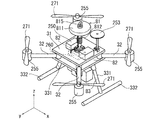
- FIG. 1 is a front view of a charging system 1 that is feeding power to an unmanned air vehicle 3 by non-contact power feeding. It is the perspective view which looked at the unmanned air vehicle 3 of the state which can fly from the front diagonally upward.
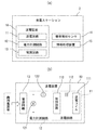
- A is a figure which shows the hardware constitutions of the charging station 2
- (b) is a figure which shows the circuit structure of the power transmission apparatus 10.
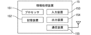
- FIG. It is a figure which shows the hardware constitutions of the information processing apparatus 15 shown to Fig.3 (a).
- 2 is a diagram illustrating a hardware configuration of an unmanned air vehicle 3.
- FIG. It is a figure which shows the function with which the control circuit 251 shown in FIG. 6 is provided.
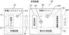
- FIG. 2 is a diagram illustrating a configuration of a power receiving device 20.
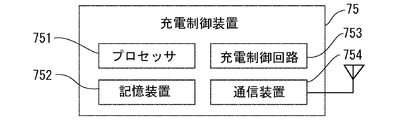
- FIG. It is a figure which shows the hardware constitutions of the charging control apparatus. It is a figure which shows the function (software structure) with which the charge control apparatus 75 is provided.
- 3 is a perspective view of a power receiving coil unit 81.
- FIG. 4 is a schematic diagram for explaining an electrical connection relationship among a power receiving coil unit 81, a control unit 82, a wiring cable 83, and a battery 260.
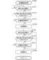
- FIG. It is a flowchart explaining power transmission control processing S1300. It is a flowchart explaining charge control processing S1400.
- FIG. 1 and 2 show a configuration of an unmanned air vehicle charging system (hereinafter referred to as a charging system 1), which is described as one embodiment of the present invention.
- the charging system 1 includes an unmanned air vehicle 3 that receives power supply by contactless power feeding (also referred to as wireless power feeding) and a charging station 2 that supplies power to the unmanned air vehicle 3 by non-contact power feeding.
- FIG. 1 is a front view of a charging system 1 that is feeding power to an unmanned air vehicle 3 by non-contact power feeding
- FIG. 2 is a perspective view of the unmanned air vehicle 3 in a flightable state as viewed from obliquely upward from the front.
- the unmanned air vehicle 3 is used for various purposes such as shooting aerial images and transporting luggage.
- the unmanned aerial vehicle 3 is, for example, a multicopter (such as a bicopter tricopter, a quadcopter, a hexacopter, an octocopter), a helicopter, an airplane, a flying robot, or the like.
- the unmanned aerial vehicle 3 may be of a type that is remotely operated in a wireless manner, or of a type that autonomously flies with an autonomous control mechanism. In the present embodiment, it is assumed that the unmanned air vehicle 3 is a quadcopter of a type that is remotely controlled by a wireless system.
- the unmanned aerial vehicle 3 extends in the horizontal direction at 45 °, 135 °, 225 °, and 315 ° as the basic skeleton (frame) with respect to the pedestal portion 31 and the + y direction, respectively.
- four legs 32 (including a leg column 331 and a horizontal leg 332 described later, which are also referred to as skids) provided so as to extend below the base 31 (in the ⁇ z direction).
- the arm 32 and the leg portion 33 are configured using, for example, a tubular (cylindrical, rectangular, etc.) member or a truss-shaped member. These are made of, for example, resin, metal, or the like.
- the pedestal portion 31 has a structure having a plurality of stages of plate members in the vertical direction (z-axis direction) (in this example, two stages of upper and lower plates).
- the leg part 33 is fixed to the two leg struts 331 extending from the pedestal part 31 in the left-right direction ( ⁇ x axis direction) and extending downward by a predetermined length, and to the lower end of the leg strut 331 (see FIG. and a horizontal leg 332 extending in a predetermined length (for example, a length in the front-rear direction (y-axis direction) of the unmanned air vehicle 3) in the y-axis direction).
- the horizontal leg 332 is connected to the leg column 331 through a T-shaped connecting member or the like in the vicinity of the center in the longitudinal direction (y-axis direction).
- the horizontal leg 332 is not an essential configuration, and for example, the leg portion 33 may be configured by four leg columns 331.
- a flight control device 250 is provided on the upper stage of the pedestal 31.
- a lower part of the pedestal 31 is provided with a part of the power receiving device 20 described later, a battery 260 (power storage device), a control unit 82 described later, and the like. These are fixed to the pedestal 31 using, for example, a double-sided tape or a hook-and-loop fastener.
- a power motor 255 (thrust generator) is provided with the direction of the rotation axis directed in the vertical direction (z-axis direction).
- a propeller 271 (rotary blade) is attached to the rotating shaft of each power motor 255.
- Each power motor 255 is connected to a motor control device 254 described later.
- the load 41 is, for example, a pickup when the unmanned aerial vehicle 3 is used for collection and delivery of luggage, and, for example, when the unmanned aerial vehicle 3 is used for aerial photography purposes, a photographic equipment (camera, video camera, stabilizer) is used. , Gimbals, vibration buffers, etc.).
- the charging station 2 includes a casing 201 having a flat rectangular shape.
- the casing 201 is fixed to the structure 8 existing above.
- the structure 8 may be a movable type (for example, a roof in the room of the equipment carrier of the unmanned air vehicle 3) or a fixed type fixed on the ground or the like.
- the casing 201 is provided with a power transmission device 10 and a body detection sensor 14 that perform power transmission to the unmanned air vehicle 3 by non-contact power feeding.
- the output signal of the airframe detection sensor 14 is used to determine whether or not the unmanned air vehicle 3 is present at a predetermined position.
- a spiral-type power transmission coil 111 which is a component of the power transmission device 10, is provided on the lower surface side of the housing 201.
- the power transmission coil 111 is provided so that the power transmission surface is horizontal (the direction of the winding axis of the power transmission coil 111 is vertical).
- a hook 7 constituting a hanging structure of the unmanned air vehicle 3 is provided on the winding axis of the power transmission coil 111.
- the unmanned air vehicle 3 is provided with a power receiving device 20 that receives power transmitted from the power transmitting device 10 by non-contact power feeding.
- the power receiving device 20 includes a power receiving coil 211 and a rectifying circuit 22 that constitute a power receiving unit that receives power transmitted from the power transmitting coil 111 of the power transmitting device 10.
- the non-contact power supply is a magnetic resonance method (AC resonance method or DC resonance method) as an example, but the non-contact power supply method is not necessarily limited to the same method.
- the charging system 1 can be realized by other contactless power feeding methods such as an “electromagnetic induction method” and a “microwave method”.
- a power receiving coil unit 81 containing the power receiving coil 211 is detachably provided on the upper surface of the base 31 of the unmanned air vehicle 3.
- a control unit 82 on which the rectifier circuit 22 and the like are mounted is provided below the pedestal 31.
- the control unit 82 is further equipped with a charge control device 75 described later.
- the power receiving coil unit 81 and the control unit 82 are electrically connected via a wiring cable 83.
- the power receiving coil unit 81 that further includes the control unit 82 and the charging control device 75 may be collectively referred to as the power receiving coil unit 81.
- the power receiving coil unit 81 includes a case 811 in which the spiral power receiving coil 211 is accommodated, a support column 812 that supports the case 811 at a predetermined height, and a lower end of the support column 812. And a fixing portion 813 for fixing to 31.
- the power receiving coil 211 is provided at a position (+ z side) higher than the upper surface of the pedestal portion 31 by the support pillar 812.
- the pedestal 31 is further provided at a position higher than the power motor 255 and the propeller 271.
- the unmanned air vehicle 3 is in a state where a GPS antenna, which is one of various sensors 253, is erected on the upper surface of the pedestal portion 31.
- the power receiving coil 211 is preferably provided at a position lower than the GPS antenna so as not to affect reception.
- the power receiving coil 211 is provided such that its power receiving surface faces in the horizontal direction (so that the winding axis direction of the power receiving coil 211 faces in the vertical direction).
- a ring body 815 for suspending the unmanned air vehicle 3 on the hook 7 described above is provided on the winding shaft at the upper part of the power receiving coil 211.
- the power receiving surface of the power receiving coil 211 is horizontal (so that the power receiving surface of the power receiving coil 211 and the power transmitting surface of the power transmitting coil 111 are parallel).
- the power receiving coil unit 81 is preferably provided in the unmanned air vehicle 3 so that the winding axis of the power receiving coil 211 passes through the center of gravity of the unmanned air vehicle 3 or the vicinity of the center of gravity.
- the hook 7 is provided on the charging station 2 side.
- a hook is provided on the unmanned air vehicle 3 side, and a locking portion (ring body, etc.) is provided on the charging station 2 side. May be.
- the hanging structure of the unmanned air vehicle 3 is not necessarily limited to that using such a hook and a locking part (ring body or the like).
- the ring body 815 is placed not at the upper part of the power receiving coil 211 but at the center of the power receiving coil 211 so that the power receiving coil 211 is disposed at a position close to the power transmitting coil 111. It may be provided at a position close to (such as being embedded near the center of the power receiving coil 211).
- FIG. 3A shows a hardware configuration (block diagram) of the charging station 2.
- the charging station 2 includes a power transmission device 10, a body detection sensor 14, and an information processing device 15.
- FIG. 3B shows a circuit configuration of the power transmission device 10.
- the power transmission device 10 includes a power transmission circuit 11, a power measurement circuit 12, and a power supply circuit 13.
- the power transmission circuit 11 includes a power transmission coil 111, a capacitive element 112, and a control circuit 113.
- the power measurement circuit 12 includes a voltmeter 121 and an ammeter 122 that measure the power supplied from the power supply circuit 13 to the power transmission circuit 11.
- the measurement value of the power measurement circuit 12 is input to the information processing device 15 or the like.
- the power transmission coil 111 may be capable of adjusting the inductance in order to improve the transmission efficiency of the non-contact power feeding.
- the capacitive element 112 may be capable of adjusting the capacitance so as to improve the transmission efficiency of contactless power feeding.
- the power supply circuit 13 includes, for example, an AC / DC converter and a regulator (switching regulator, linear regulator, etc.), and supplies power supplied from a commercial power supply to the power transmission circuit 11 and the information processing device 15, for example. .
- the control circuit 113 generates a drive current having a predetermined frequency to be supplied to the power transmission circuit 11.
- the control circuit 113 includes, for example, a driver circuit (gate driver, half-bridge driver, etc.), a high frequency amplifier, and a matching circuit (matching circuit).
- the output signal of the airframe detection sensor 14 indicates that the unmanned aerial vehicle 3 is present at a predetermined position (for example, the power receiving coil 211 is present in the vicinity of the power transmitting coil 111 and the power transmitting coil 111 transmits power). For example, whether the area and the power receiving area of the power receiving coil 211 are just facing each other).
- the body detection sensor 14 is configured using, for example, one or more photoelectric sensors disposed at a predetermined position of the charging station 2.
- the body detection sensor 14 is configured using, for example, a pressure sensor, a distance measurement sensor, or the like.
- the airframe detection sensor 14 uses, for example, a sensor (for example, a pressure sensitive sensor, a strain gauge, etc.) for detecting a change in load applied to the hook 7 when the unmanned air vehicle 3 is suspended from the hook 7. Configured.
- FIG. 4 shows a hardware configuration (block diagram) of the information processing apparatus 15 (computer) shown in FIG.
- the information processing apparatus 15 includes a processor 151, a storage device 152, an input device 153, an output device 154, and a communication device 155. These are connected to be communicable via a communication means such as a bus.
- the processor 151 is configured using, for example, a CPU (Central Processing Unit) or an MPU (Micro Processing Unit).
- the storage device 152 is a device that stores programs and data, and is, for example, a ROM (Read Only Memory), a RAM (Random Access Memory), an NVRAM (Non Volatile RAM), or the like.
- the processor 151 and the storage device 152 may be provided as, for example, a microcomputer (microcomputer) in which these are packaged together.
- the input device 153 is an interface that receives input of information and instructions from the user, and is, for example, a keyboard, a mouse, a touch panel, or the like.
- the output device 154 is an interface that provides information to the user, and is, for example, a liquid crystal panel (Liquid Crystal Display), an LED (Light Emitting Diode), a speaker, or the like.
- the communication device 155 performs wireless communication with a communication device 259 on the unmanned air vehicle 3 described later and a communication device 754 of the charging control device 75. This wireless communication is performed using, for example, a 2.4 GHz band radio wave.
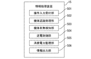
- FIG. 5 shows functions (software configuration) included in the information processing apparatus 15.
- the information processing apparatus 15 includes functions of an operation input receiving unit 501, a machine body recognition processing unit 502, a machine body presence / absence detection unit 503, a power transmission control unit 504, a power consumption monitoring unit 505, and an information output unit 506. Is provided. These functions are realized by, for example, the processor 151 reading and executing a program stored in the storage device 152.
- the operation input receiving unit 501 receives an operation input from the user via the input device 153. For example, the operation input reception unit 501 determines whether or not the user has performed a power transmission start operation (power supply permission operation) or a power transmission stop operation, and notifies the power transmission control unit 504 of the result.
- a power transmission start operation power supply permission operation
- a power transmission stop operation a power transmission stop operation
- the aircraft recognition processing unit 502 performs an authentication process based on authentication information acquired from the unmanned air vehicle 3 (for example, an identification number or a registration number unique to each unmanned air vehicle 3).
- the authentication information is acquired, for example, when the communication device 155 wirelessly communicates with a communication device 754 of the charge control device 75 described later.
- the airframe recognition processing unit 502 authenticates the unmanned air vehicle 3, thereby preventing, for example, theft prevention or malfunction of other company's products.
- the aircraft presence / absence detection unit 503 detects whether or not the unmanned air vehicle 3 is present at a predetermined position based on information input from the aircraft detection sensor 14.
- the power transmission control unit 504 controls the magnitude (output) of power transmitted from the power transmission coil 111 and the presence / absence of power transmission. For example, the power transmission control unit 504 controls the presence / absence of power transmission from the power transmission coil 111 in response to a notification from the operation input receiving unit 501 (for example, a notification that the user has performed a power transmission start operation or a power transmission stop operation). The power transmission control unit 504 controls the presence / absence of power transmission from the power transmission coil 111 based on the determination result of the airframe presence / absence detection unit 503, for example.
- the power transmission control unit 504 controls the duty ratio in the PWM control of the driver circuit of the control circuit 113, the coupling coefficient between the power transmission circuit 11 and the power reception circuit 21, the capacitance of the capacitive element 112, and the power supply circuit 13. This is performed by changing one or more of the power supply amount to the circuit 113 and the power supply amount from the control circuit 113 to the power transmission coil 111.
- the power transmission control unit 504 may have a function of automatically adjusting the inductance of the power transmission coil 111 and the capacitance of the capacitive element 112 so that the transmission efficiency of contactless power feeding is improved.
- the power transmission control unit 504 grasps the transmission efficiency based on, for example, the ratio between the transmitted power from the power transmission circuit 11 and the received power of the power receiving device 20 acquired by wireless communication with the charging control device 75 described later. . Moreover, the power transmission control unit 504 grasps the transmission efficiency based on the measurement value of the power measurement circuit 12, for example.
- the power consumption monitoring unit 505 monitors the power consumption of the power transmission circuit 11 as needed based on information (voltage value, current value) obtained from the power measurement circuit 12.
- the information output unit 506 outputs various information to the output device 154.
- FIG. 6 shows a hardware configuration (block diagram) of the unmanned air vehicle 3.
- the unmanned air vehicle 3 includes a power receiving device 20, a charging control device 75, a battery 260, a flight control device 250, and a thrust generating device 270.
- the flight control device 250 and the thrust generation device 270 are operated by electric power supplied from the battery 260.
- the charging control device 75 operates with electric power supplied from the power receiving device 20.
- the flight control device 250 includes a control circuit 251, a receiver 252, various sensors 253, an output device 258, a communication device 259, and a battery 260.
- the control circuit 251 includes a processor and a storage element and functions as an information processing apparatus.
- the control circuit 251 may be realized, for example, as a microcomputer (microcomputer) in which a processor and a storage element are integrally packaged.
- the various sensors 253 are, for example, a 3-axis gyro sensor (angular velocity sensor), a 3-axis acceleration sensor, an atmospheric pressure sensor, a magnetic sensor, an ultrasonic sensor, a GPS (Global Positioning System) signal receiver, and the like.
- the three-axis gyro sensor detects, for example, the front / rear / left / right inclination and the angular velocity of rotation of the unmanned air vehicle 3.
- the triaxial acceleration sensor detects, for example, the acceleration of the unmanned air vehicle 3 (acceleration in the front / rear / right / left / up / down directions).
- the atmospheric pressure sensor measures the atmospheric pressure for obtaining the altitude and the ascending / descending speed of the unmanned air vehicle 3.
- the magnetic sensor detects, for example, the direction in which the aircraft's axis is currently facing.
- the ultrasonic sensor detects, for example, the distance between the unmanned air vehicle 3 and the ground, wall, obstacle or the like.
- the unmanned aerial vehicle 3 does not necessarily have to include all the sensors exemplified above.
- the receiver 252 receives the radio signal transmitted from the remote control transmitter 6 and inputs the content of the received radio signal to the control circuit 251.
- the output device 258 is an interface that provides information to the user, such as an LED or a speaker.
- the communication device 259 performs wireless communication with the communication device 155 on the charging station 2 side, for example.
- the communication device 259 performs wired communication or wireless communication with a communication device 754 of the charge control device 75 described later.
- the battery 260 is, for example, a lithium polymer secondary battery, an electric double layer capacitor (electric double layer capacitor), a lithium ion secondary battery, or the like.
- the voltage between the terminals of the battery 260 is input to the control circuit 251.
- the control circuit 251 grasps the remaining amount of the battery 260 based on the inter-terminal voltage. For example, the control circuit 251 outputs information indicating the current remaining amount of the battery 260 from the output device 258.
- the control circuit 251, the charging control device 75, and the charging station 2 may communicate with each other and share information held by each of them.
- the thrust generator 270 includes a motor controller 254 and a power motor 255.
- a motor control device 254 also referred to as an ESC (Electronic Speed Controller), an amplifier, or the like) controls the rotation of the power motor 255 by, for example, electrical resistance value control or PWM (Pulse Width Modulation) control.
- the motor control device 254 generates thrust for flight.
- the control circuit 251 controls the operation (posture (pitch, roll, yaw), movement (position (pitch, roll, yaw)) of the unmanned air vehicle 3 by controlling the rotational speed of each of the plurality of power motors 255 based on information input from the various sensors 253. Forward, backward, left and right movement, ascending, descending, etc.).
- the power motor 255 is an electric motor, for example, a brushless motor.
- control circuit 251 includes an attitude control unit 801 and a steering control unit 802. These functions are realized, for example, when the processor of the control circuit 251 reads and executes a program stored in the storage device of the control circuit 251.
- the attitude control unit 801 controls the motor control device 254 (power motor 255) according to signals input from the various sensors 253, and controls the flight attitude of the unmanned air vehicle 3.
- the steering control unit 802 controls the motor control device 254 (power motor 255) according to the signal input from the receiver 252 and controls the operation of the unmanned air vehicle 3.
- FIG. 8 shows the configuration of the power receiving device 20.
- the power receiving device 20 rectifies the power received by the power receiving circuit 21 (including the power receiving coil 211 and the capacitor 212) that performs magnetic resonance type non-contact power feeding, and loads ( The rectifier circuit 22 supplied to the flight control device 250, the battery 260 and the like, and the received power supplied to the load are measured, and the measured value is input to the charge control device 75 (voltmeter 241 and current). Including a total of 242).
- the power receiving coil 211 may be capable of adjusting the inductance.
- the capacitor 212 may be one that can adjust the capacitance.
- the power receiving coil unit 81 is mounted with the power receiving coil 211 and the capacitive element 212 of the power receiving circuit 21.
- the control unit 82 includes the rectifier circuit 22, the power measurement circuit 24, and the charge control device 75.
- the capacitive element 212 may be mounted on the control unit 82, for example.
- FIG. 9 shows a hardware configuration (block diagram) of the charging control device 75.
- the charge control device 75 includes a processor 751, a storage device 752, a charge control circuit 753, and a communication device 754. These are connected to be communicable via a communication means such as a bus.
- the processor 751 is configured using, for example, a CPU or MPU.
- the storage device 752 is a device that stores programs and data, and is, for example, a ROM, a RAM, an NVRAM, or the like.
- the processor 751 and the storage device 752 may be provided as, for example, a microcomputer (microcomputer) in which these are packaged together.
- the charge control circuit 753 includes a charge control circuit that performs control in order to efficiently charge the battery 260, a voltage monitoring circuit between the terminals of the battery 260, various protection circuits, and the like.
- the communication device 754 performs wireless communication with the communication device 155 of the charging station 2.
- the communication device 754 performs wired communication or wireless communication with the communication device 259 of the flight control device 250.
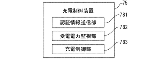
- FIG. 10 shows functions (software configuration) included in the charge control device 75.
- the charging control device 75 includes functions of an authentication information transmitting unit 781, a received power monitoring unit 782, and a charging control unit 783. These functions are realized, for example, when the processor 751 reads and executes a program stored in the storage device 752. Note that the flight control device 250 may realize all or part of the functions of the charge control device 75.
- the authentication information transmission unit 781 stores the authentication information and transmits the authentication information to the charging station 2 via the communication device 754.
- the received power monitoring unit 782 monitors the received power based on the voltage or current measurement value input from the power measurement circuit 24 of the power receiving device 20.
- the received power monitoring unit 782 notifies the charging station 2 of the measured value (received power) at any time by wireless communication via the communication device 754.
- the received power monitoring unit 782 may have a function of automatically adjusting the inductance of the power receiving coil 211 and the capacitance of the capacitive element 212 so that the transmission efficiency of non-contact power feeding is improved.
- the charging control unit 783 charges the battery 260 by efficiently supplying the received power to the battery 260 while monitoring the measured value of the voltage or current input from the power measuring circuit 24 or the voltage between the terminals of the battery 260. For example, the charging control unit 783 charges the battery 260 while performing control of a CVCC (Constant Voltage. Constant Current) method. In addition, the charging control unit 783 notifies the information processing device 15 of the charging station 2 as needed, for example, the voltage between the terminals of the battery 260 and information on the progress of charging. In addition, the charging control unit 783 performs charging control of the battery 260 in accordance with, for example, an instruction sent from the information processing device 15 of the charging station 2.
- CVCC Constant Voltage. Constant Current
- the charging control unit 783 shares information about the battery 260 (maximum charging capacity, appropriate charging voltage, appropriate charging current, etc.) by communication with the charging station 2, and based on these information, the charging control unit 783 or The charging station 2 may be configured to perform charging control of the battery 260, monitoring of a charging state, and the like.
- FIGS. 11A to 11C show the configuration of the power receiving coil unit 81.
- FIG. 11A is a perspective view of the power receiving coil unit 81
- FIG. 11B is a side view of the power receiving coil unit 81
- FIG. 11C is a view of the power receiving coil unit 81 from above. It is a top view.
- the power receiving coil unit 81 has a flat and substantially rectangular parallelepiped appearance.
- the length of the power receiving coil unit 81 in the longitudinal direction is set to, for example, the same length as the length of the horizontal leg 332 in the longitudinal direction.
- the power receiving coil unit 81 includes a case 811 having a substantially cylindrical shape, a power receiving coil 211 housed inside the case 811, and a case 811 extending vertically from the pedestal portion 31 to a predetermined height.
- the support column 812 supported at the vertical position, the ring body 815 provided at the upper end of the support column 812, the adjusting mechanism 8121 for adjusting the length of the support column 812, and the lower end of the support column 812 are fixed to the upper surface of the pedestal 31.
- a fixing portion 813 is provided.
- the total weight of the unmanned flying body 3 is applied to the ring body 815, the support column 812, and the fixing portion 813.
- the support column 812, the fixing portion 813, and the pedestal portion 31 are firmly coupled to each other by screwing, integral molding, or the like.
- the case 811 is configured using an insulating material such as resin.
- the case 811 is fixed on an annular plate 8122 provided at a predetermined height position of the support column 812. From the viewpoint of aerodynamic characteristics, it is preferable that the case 811 has a streamline shape or a shape close to a streamline shape.
- the power receiving coil 211 is a spiral type wound around the support column 812, and is arranged inside the case 811 so that the direction of the winding axis is vertical. Note that a capacitive element 212 of the power receiving circuit 21 is mounted at a predetermined position of the case 811.
- the adjustment mechanism 8121 is a mechanism for adjusting the length of the support column 812.
- the user can freely extend and contract the length of the support column 812 in the longitudinal direction by rotating the adjustment mechanism 8121 around the axis of the support column 812.
- the adjustment mechanism 8121 By operating the adjustment mechanism 8121, the user operates the adjustment mechanism 8121 to transmit power when receiving power from the power transmission coil 111, the relationship with various devices arranged on the pedestal unit 31, the influence of electromagnetic noise generated during power supply by non-contact power supply, and the like.
- the case 811 (the power receiving coil 211) can be set at an appropriate height position.
- a wiring cable 83 connected to two terminals of the power receiving coil 211 inside the case 811 extends from a predetermined portion of the case 811.
- the other end of the wiring cable 83 is connected to a control unit 82 provided at the lower stage of the pedestal 31.
- FIG. 12 is a schematic diagram for explaining an electrical connection relationship between the power receiving coil unit 81, the control unit 82, the wiring cable 83, and the battery 260.
- a wiring cable 83 is connected to the control unit 82 and a charging terminal of a battery 260 is connected via a charging cable 84.
- a pair of connectors 85 a and 85 b are provided in the middle of the charging cable 84.
- the user attaches the power receiving coil unit 81, the control unit 82, and the wiring cable 83 to the existing unmanned aerial vehicle 3, and then connects the connector 85a and the connector 85b, thereby the existing unmanned aerial vehicle 3 is connected.
- the control unit 82 since the control unit 82 has a function of communicating with the charging station 2, the charging station 2 communicates with the control unit 82, monitors the power reception status and transmission efficiency of non-contact power feeding, It is possible to control charging 260, check the progress of charging, and the like. Further, as described above, since the control unit 82 has a function of transmitting authentication information, the charging station 2 can authenticate the unmanned air vehicle 3 based on the authentication information notified from the control unit 82.
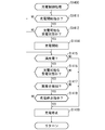
- FIG. 13 is a flowchart illustrating a process performed in charging station 2 (hereinafter referred to as power transmission control process S1300).
- power transmission control process S1300 a process performed in charging station 2
- the power transmission control process S1300 will be described with reference to FIG.
- the aircraft recognition processing unit 502 receives the authentication information from the charging control device 75 mounted on the unmanned air vehicle 3, and performs the above determination by performing authentication based on the received authentication information (S1311: NO).
- the airframe recognition processing unit 502 recognizes the unmanned air vehicle 3 (successful authentication) (S1311: YES)
- the airframe presence / absence detecting unit 503 of the charging station 2 determines whether the unmanned air vehicle 3 exists at a predetermined position. It is determined whether or not (S1312). If the airframe presence / absence detection unit 503 determines that the unmanned air vehicle 3 is present at a predetermined position (S1312: YES), the process proceeds to S1313. When the airframe presence / absence detection unit 503 determines that the unmanned aerial vehicle 3 does not exist at the predetermined position (S1312: NO), the process returns to S1311. In the case of the present embodiment, if the unmanned air vehicle 3 is suspended from the hook 7, the airframe presence / absence detection unit 503 determines that the unmanned air vehicle 3 exists at a predetermined position.
- the operation input reception unit 501 of the charging station 2 determines whether or not the user has performed a power transmission start operation (power supply permission operation) (S1313: NO). If it is determined that the user has performed a power transmission start operation (S1313: YES), this is notified to the power transmission control unit 504, and the power transmission control unit 504 starts power transmission by non-contact power feeding (energizes the power transmission coil 111) (S1314). ).
- a power transmission start operation power supply permission operation
- the airframe presence / absence detection unit 503 automatically determines that the unmanned air vehicle 3 is currently present at the predetermined position (S1312: YES) and automatically transmits power.
- the control unit 504 may start power transmission. Prior to the start of power transmission, the power transmission control unit 504 attempts to communicate with the flight control device 250 in order to prevent the flight control device 250 from malfunctioning due to the influence of noise generated during non-contact power feeding. Power transmission may be started after confirming that the operation has stopped.
- the airframe recognition processing unit 502 monitors in real time whether or not the unmanned air vehicle 3 can be recognized (S1315). When the aircraft recognition processing unit 502 cannot recognize the unmanned air vehicle 3 (S1315: NO), it notifies the power transmission control unit 504 to that effect, and the power transmission control unit 504 stops the power transmission (S1318). Thereafter, the process returns to S1311.
- the aircraft presence / absence detection unit 503 monitors in real time whether or not the unmanned air vehicle 3 is present at a predetermined position (S1316).
- the airframe presence / absence detection unit 503 notifies the power transmission control unit 504 to that effect, and the power transmission control unit 504 stops the power transmission in response to this ( S1318). Thereafter, the process returns to S1311.
- the operation input receiving unit 501 monitors in real time whether or not the user has performed a power transmission stop operation (S1317). When the operation input reception unit 501 determines that the user has performed a power transmission stop operation (S1317: YES), the operation input reception unit 501 notifies the power transmission control unit 504 to that effect, and the power transmission control unit 504 stops the power transmission (S1318). . Thereafter, the process returns to S1311.
- FIG. 14 is a flowchart illustrating a process (hereinafter referred to as a charge control process S1400) performed by the charge control device 75 attached to the unmanned air vehicle 3 when charging the battery 260 with the power received by the non-contact power supply. .
- a charge control process S1400 will be described with reference to FIG.
- the charging control unit 783 of the charging control device 75 determines whether or not a charging start instruction has been received from the charging station 2 (S1411). When it is determined that the charge control device 75 has received a charge start instruction (S1411: YES), the process proceeds to S1412.
- the charging control unit 783 of the charging control device 75 determines whether or not the power receiving state of the power receiving device 20 by the non-contact power feeding is a chargeable state based on the information notified from the received power monitoring unit 782. For example, the charging control unit 783 determines whether the voltage value (or current value) measured by the voltmeter 241 (or ammeter 242) of the power measurement circuit 24 exceeds a preset voltage threshold (or current threshold). (Whether or not the power necessary for the flight can be received) is determined to determine whether or not the power receiving state is a chargeable state. When the charging control unit 783 determines that the power receiving state of the power receiving device 20 is a chargeable state (S1412: YES), the process proceeds to S1414. When the charging control unit 783 determines that the power receiving state of the power receiving device 20 is not a state in which charging is possible (S1412: NO), the process returns to S1411.
- the charging control unit 783 of the charging control device 75 starts charging the battery 260 with the power received by the power receiving device 20.
- the charging control unit 783 monitors whether the battery 260 is fully charged by monitoring the voltage between terminals of the battery 260, the amount of charge (the amount of current flowing into the battery 260), and the like. (S1415). If the charging control unit 783 determines that the battery 260 is fully charged (S1415: YES), the charging control unit 783 stops the current supply to the battery 260 (S1419). Thereafter, the process returns to S1411. If the charging control unit 783 determines that the battery 260 is not fully charged (S1415: NO), the process proceeds to S1416.
- the charging control unit 783 determines whether or not the power receiving state of the power receiving device 20 by non-contact power feeding is a chargeable state in the same manner as in S1412.
- the charging control unit 783 determines that the power receiving state of the power receiving device 20 is a chargeable state (S1416: YES)
- the process proceeds to S1417.
- the charging control unit 783 stops the current supply to the battery 260 (S1419). Thereafter, the process returns to S1411.
- the charging control unit 783 determines whether any abnormality has been detected based on information notified from the charging control device 75 or the like. If no abnormality is detected (S1417: YES), the process proceeds to S1418. When any abnormality is detected (S1417: YES), the charging control unit 783 stops the current supply to the battery 260 (S1419). Thereafter, the process returns to S1411.
- the charging control unit 783 determines whether a charging stop instruction has been received from the charging station 2 (S1418). When it is determined that the charge control device 75 has not received a charge stop instruction (S1418: NO), the process returns to S1415. When it is determined that the charge control device 75 has received the charge stop instruction (S1418: YES), the charge control unit 783 stops the current supply to the battery 260 (S1419). Thereafter, the process returns to S1411.
- the power receiving coil 211 that receives power by non-contact power feeding is provided on the unmanned air vehicle 3 so as to be higher than the pedestal portion 31, a load is placed below the pedestal portion 31.
- the space S to be arranged can be secured.
- the power receiving coil 211 is provided at a position higher than the pedestal 31, power can be supplied efficiently by bringing the power transmitting coil 111 close to the upper part of the unmanned air vehicle 3 without being blocked by a metal part or the like of the airframe.
- the power receiving coil 211 can be provided at a position away from the flight control device 250, and the influence of electromagnetic noise during power feeding on the flight control device 250 can be suppressed.
- the unmanned air vehicle 3 is provided with a suspension structure (hook 7) for suspending in the vicinity of the power transmission coil 111 disposed above the power receiving coil 211, the unmanned air vehicle 3 is suspended (hook 7).
- the power receiving coil 211 can be brought close to the power transmitting coil 111 in an appropriate state simply by suspending the power receiving coil 211, and non-contact power feeding can be easily performed.
- the positional relationship between the power transmission coil 111 and the power reception coil 211 is determined simply by suspending it from the suspension structure (the ring body 815 is positioned at the lowest point (dynamically stable point) of the curved portion of the hook 7).
- Adjustment and setting of the distance between the coil 111 and the power receiving coil 211 are not required, and charging can be started quickly and easily.
- the power transmission coil 111 is provided on the ceiling surface of the vehicle, so that the unmanned flying vehicle 3 can be easily suspended only by suspending it from the suspension structure (hook 7). Contact power feeding can be performed, and the floor space in the vehicle can be used effectively.
- the unmanned air vehicle 3 is provided with the rectifier circuit 22 that rectifies the power received by the power receiving coil 211 and the charge control device 75 that charges the battery 260 with the power rectified by the rectifier circuit 22, the user
- the battery 260 can be charged using the power received by the power receiving coil 211 without separately preparing the rectifier circuit 22 and the charging control device 75 when charging the battery 260.
- the power receiving coil 211 is provided at a position higher than the thrust generator such as the power motor 255 and the propeller 271, the power receiving coil can be provided at a safe position away from the thrust generator.
- the unmanned air vehicle 3 can receive power by non-contact power feeding and can easily charge the battery 260 with the received power. Can be realized.
- the configuration in which electric power is supplied to the unmanned aerial vehicle 3 by non-contact power feeding has been shown.
- the inventive concept of arranging the power receiving unit on the upper part of the unmanned air vehicle 3 is based on the contact power feeding to the unmanned air vehicle 3.
- the present invention can be commonly applied to a configuration for supplying power.
- a power receiving electrical connector or the like constitutes a power receiving unit.
- the power receiving coil 211 provided in the power receiving coil unit 81 has been described as a spiral type, but the mode of the power receiving coil 211 is not necessarily limited.
- a helical coil may be used as the power receiving coil 211.
- the power transmission coil 111 and the power reception coil 211 are arranged so that the winding axis of the helical coil of the power transmission coil 111 and the winding axis of the power reception coil 211 are coaxial. And charge it.
- the unmanned air vehicle 3 autonomously approaches the charging station 2 and hooks 7.
- the ring body 815 may be connected to the hook 7.
- the power transmission surface of the power transmission coil 111 and the power reception surface of the power reception coil 211 may be shifted.
- the power transmission surface of the power transmission coil 111 and the power reception surface of the power reception coil 211 are accurately and reliably Can be face to face.
- the unmanned air vehicle 3 autonomously approaches the charging station 2 and automatically connects. It is good also as a structure connected with the charging station 2 via a mechanism (a mechanical thing, the thing using an electromagnet etc.) (The power transmission area
- each of the above-described configurations, function units, processing units, processing means, and the like may be realized by hardware by designing a part or all of them, for example, with an integrated circuit.
- Each of the above-described configurations, functions, and the like may be realized by software by the processor interpreting and executing a program that realizes each function.
- Information such as programs, tables, and files for realizing each function can be stored in a recording device such as a memory, a hard disk, or an SSD (Solid State Drive), or a recording medium such as an IC card, an SD card, or a DVD.
- control lines and information lines indicate what is considered necessary for explanation, and not all control lines and information lines on the mounting are necessarily shown. For example, it may be considered that almost all configurations are actually connected to each other.
- the arrangement form of various functional units in the charging system 1 described above is merely an example.
- the arrangement form of various functional units can be changed to an optimum arrangement form from the viewpoint of the performance of hardware and software provided in the charging system 1, processing efficiency, communication efficiency, and the like.
Landscapes
- Engineering & Computer Science (AREA)
- Aviation & Aerospace Engineering (AREA)
- Mechanical Engineering (AREA)
- Remote Sensing (AREA)
- Computer Networks & Wireless Communication (AREA)
- Chemical & Material Sciences (AREA)
- Combustion & Propulsion (AREA)
- Charge And Discharge Circuits For Batteries Or The Like (AREA)
Abstract
無人飛行体(3)の性能や機能等に与える影響を抑えつつ無人飛行体3に非接触給電により電力を受電する仕組みを実現する。飛行制御装置(250)が設けられる台座部(31)、台座部(31)から周方向に所定長さで延出し、推力発生装置(255)が設けられる複数のアーム、飛行制御装置(250)又は推力発生装置(255)に電力を供給する蓄電装置(バッテリ(260))、台座部(31)の下方に積載物(41)を搭載するための空間(S)を確保しつつ、台座部(31)の下方に延出して設けられる脚支柱(331)を備える無人飛行体(3)に、台座部(31)よりも高い位置に設けられ、非接触給電により蓄電装置に供給する電力を受電する受電コイル(211)を設ける。
Description
本発明は、無人飛行体、受電コイルユニット、及び充電システムに関する。
特許文献1には、非接触電力伝送における人体への影響を少なくするため、受電コイルを、電力伝送時のみ、バスの外部に突出するように構成し、バスの上方に、送電コイルと補助コイルを左右方向に対向して配置して受電空間を形成することが記載されている。
特許文献2には、顧客に向けて確実に荷物を配送する無人飛行体による配送方法について記載されている。無人飛行体は、配送先においてホバリングし、カメラによって配送先の映像を撮影し、その映像に基づいて荷物引渡の適否を判断する。
非特許文献1には、太陽光パネル監視などに向けた、ワイヤレス給電対応のドローン(無人飛行機)について記載されている。ドローンが充電台に着陸すると、ワイヤレス給電により内蔵バッテリを充電する。バッテリを充電している間はドローンのLEDが緑色に点灯する。
非特許文献2には、ドローンやロボット向けのワイヤレス給電システムについて記載されている。またワイヤレス給電システムによれば、ドローンからバッテリを外す手間を省略でき、不要な金属面を露出する必要がないため安全に充電できると記載されている。
非特許文献1,2に記載されているように、バッテリ交換の手間の解消や安全性の向上等を目的として、無人飛行体に搭載されているバッテリの充電を非接触給電により行うことが提案されている。ここで非接触給電によりバッテリの充電を行うためには、無人飛行体側に受電コイルを設ける必要があるが、例えば、磁界共鳴方式の非接触給電により短波帯の電磁波で給電を行おうとした場合、数十cm程度の大径の受電コイルを設ける必要があり、空力特性、安全性、積載物の搭載スペースの確保、撮影機材搭載時における撮影視野の確保、非接触給電の伝送効率の確保等、無人飛行体の性能や機能等に与える影響を考慮する必要がある。
本発明はこうした背景に鑑みてなされたものであり、無人飛行体の性能や機能に与える影響を抑えつつ、無人飛行体に非接触給電により電力を供給する仕組みを実現することが可能な、無人飛行体、受電コイルユニット、及び充電システムを提供することを目的としている。
上記目的を達成するための本発明のうちの一つは、無人飛行体であって、飛行制御装置が設けられる台座部と、前記台座部から当該台座部の周方向に所定長さで延出し、推力発生装置が設けられる複数のアームと、前記台座部の下方に積載物を搭載するための空間を確保しつつ、前記台座部の下方に延出して設けられる脚部と、前記台座部よりも高い位置に設けられ、前記飛行制御装置又は前記推力発生装置に電力を供給する蓄電装置を充電する電力を受電する受電部と、を備える。
本発明によれば、無人飛行体に、蓄電装置に供給する電力を受電する受電部を、台座部の下方に積載物が配置される空間を確保しつつ設けることができる。
本発明の他の一つは、上記無人飛行体であって、前記受電部は、非接触給電により前記蓄電装置を充電する電力を受電する受電コイルである。
本発明によれば、無人飛行体に、非接触給電により蓄電装置を充電する電力を受電する受電コイルを、台座部の下方に積載物が配置される空間を確保しつつ設けることができる。また受電コイルを台座部よりも高い位置に設けたため、機体の金属部分等によって遮られることなく無人飛行体の上方に送電コイルを近接させて効率よく給電を行うことができる。また飛行制御装置から離れた位置に受電コイルを設けることができ、給電時の電磁ノイズが飛行制御装置に与える影響を抑えることができる。
本発明の他の一つは、上記無人飛行体であって、当該無人飛行体を、前記受電コイルの上方に配置された送電コイルの近傍に吊り下げるための吊り下げ構造を有する。
本発明によれば、無人飛行体を送電コイルの下方に吊り下げるだけで受電コイルを送電コイルに対して適切な状態で近接させることができ、容易に非接触給電を行うことができる。とくに吊り下げるだけで送電コイルと受電コイルの位置が定まるため、送電コイルと受電コイルとの間の距離の調整や設定が不要であり、迅速かつ容易に充電を開始することができる。
本発明の他の一つは、上記無人飛行体であって、前記受電コイルが受電した電力を整流する整流回路と、前記整流回路により整流された電力により前記蓄電装置の充電を行う充電制御装置と、を備える。
本発明によれば、ユーザは、蓄電装置の充電に際して整流回路や充電制御装置を別途準備することなく、受電コイルが受電した電力を利用して蓄電装置を充電することができる。
本発明の他の一つは、上記無人飛行体であって、前記受電コイルは、前記推力発生装置よりも高い位置に設けられる。
本発明によれば、推力発生装置から離れた安全な位置に受電コイルを設けることができる。
本発明の他の一つは、上記無人飛行体であって、前記非接触給電は、磁界共鳴方式の非接触給電である。
本発明の他の一つは、上記無人飛行体であって、前記受電コイルはスパイラル型又はヘリカル型である。
本発明の他の一つは、飛行制御装置が設けられる台座部と、前記台座部から当該台座部の周方向に所定長さで延出し、推力発生装置が設けられる複数のアームと、前記台座部の下方に積載物を搭載するための空間を確保しつつ、前記台座部の下方に延出して設けられる脚部と、前記台座部よりも高い位置に設けられ、前記飛行制御装置又は前記推力発生装置に電力を供給する蓄電装置を充電する電力を非接触給電により受電する受電コイルと、を備える無人飛行体に設けられる受電コイルユニットであって、前記受電コイルが収容されるケースと、前記ケースを前記台座部の上方に所定高さで支持する支持柱と、前記支持柱を前記台座部に固定する固定部と、を備える。
本発明の他の一つは、受電コイルユニットであって、前記受電コイルが受電した電力を整流する整流回路と、前記整流回路により整流された電力により前記蓄電装置の充電を行う充電制御装置と、を更に備える。
本発明の受電コイルユニットを用いることで、無人飛行体に、非接触給電により電力を受電し受電した電力により蓄電装置を充電する仕組みを容易に実現することができる。
その他、本願が開示する課題、及びその解決方法は、発明を実施するための形態の欄、及び図面により明らかにされる。
本発明によれば、無人飛行体の性能や機能に与える影響を抑えつつ、無人飛行体に非接触給電により電力を供給する仕組みを実現することができる。
以下、発明を実施するための形態について説明する。尚、以下の説明において、同一の又は類似する構成について共通の符号を付して説明を省略することがある。
図1及び図2に、本発明の一実施形態として説明する、無人飛行体の充電システム(以下、充電システム1と称する。)の構成を示している。充電システム1は、非接触給電(ワイヤレス給電とも称される。)により電力供給を受ける無人飛行体3と、非接触給電により無人飛行体3に電力を供給する充電ステーション2と、を含む。図1は非接触給電により無人飛行体3に給電中の充電システム1の正面図、図2は飛行可能な状態の無人飛行体3を正面斜め上方から眺めた斜視図である。
無人飛行体3は、例えば、空撮映像の撮影や荷物の運搬等、様々な用途に用いられる。無人飛行体3は、例えば、マルチコプタ(バイコプタ(bicopter)トリコプタ(tricopter)、クアッドコプタ(quadcopter)、ヘキサコプタ(hexacopter)、オクトコプタ(octocopter)等)、ヘリコプタ、飛行機、飛行ロボット等である。無人飛行体3は、無線方式で遠隔操縦されるタイプのものであってもよいし、自律制御機構を備えて自律飛行するタイプのものであってもよい。本実施形態では、無人飛行体3は、無線方式で遠隔操縦されるタイプのクアッドコプタであるものとする。
無人飛行体3は、その基本骨格(フレーム)として、台座部31と、台座部31から+y方向を基準として、夫々、45°、135°、225°、315°の角度で水平方向に延出する4つのアーム32と、台座部31の下方(-z方向)に延出して設けられる脚部33(後述の脚支柱331,水平脚332を含む。スキッドも称される。)とを備える。アーム32や脚部33は、例えば、筒状(円筒状、角筒状等)の部材やトラス状の部材を用いて構成される。これらは例えば、樹脂や金属等を素材として構成されている。
台座部31は、上下方向(z軸方向)に複数段の板材を有する構造(本例では上下2段の板材)になっている。脚部33は、台座部31から夫々左右方向(±x軸方向)に開脚しつつ下方に所定長さで延出する2本の脚支柱331と、脚支柱331の下端に固定され水平(y軸方向)に所定長さ(例えば、無人飛行体3の前後方向(y軸方向)の長さ)で延出する水平脚332とを有する。水平脚332は、その長手方向(y軸方向)中央付近においてT字型の連結部材等を介して脚支柱331に連結されている。尚、水平脚332は、必須の構成ではなく、例えば、4つの脚支柱331によって脚部33が構成されている場合もある。
台座部31の上段には、飛行制御装置250が設けられている。また台座部31の下段には、後述する受電装置20の一部、バッテリ260(蓄電装置)、後述する制御ユニット82等が設けられている。これらは、例えば、両面テープや面ファスナ等を用いて台座部31に固定されている。
4つのアーム32の夫々の端部近傍には、その回転軸の方向を上下方向(z軸方向)に向けて動力モータ255(推力発生装置)が設けられている。各動力モータ255の回転軸にはプロペラ271(回転翼)が取り付けられている。尚、各動力モータ255には、後述するモータ制御装置254が接続されている。
同図に示すように、台座部31の下方には、台座部31の下段と2本の脚支柱331とで囲まれる空間Sが形成されており、この空間Sには、無人飛行体3の積載物41が搭載されている。積載物41は、例えば、無人飛行体3が荷物の集配に用いられる場合は集配物であり、また例えば、無人飛行体3が空撮目的で用いられる場合は撮影機材(カメラ、ビデオカメラ、スタビライザ、ジンバル、振動緩衝体等)である。
充電ステーション2は、扁平矩形状の筐体201を備える。筐体201は、上方に存在する構造物8に固定されている。構造物8は、移動式のもの(例えば、無人飛行体3の機材運搬車の室内の屋根等)であってもよいし、地上等に固定した固定式のものであってもよい。筐体201には、無人飛行体3に非接触給電による送電を行う送電装置10や機体検知センサ14が設けられている。機体検知センサ14の出力信号は、無人飛行体3が所定の位置に存在するか否かの判定に用いられる。
筐体201の下面側には、送電装置10の構成要素であるスパイラル型の送電コイル111が設けられている。送電コイル111は、その送電面が水平になるように(送電コイル111の巻回軸の方向が鉛直になるように)設けられている。同図に示すように、送電コイル111の巻回軸上には無人飛行体3の吊り下げ構造を構成するフック7が設けられている。
無人飛行体3には、送電装置10から非接触給電により送られてくる電力を受電する受電装置20が設けられている。受電装置20は、送電装置10の送電コイル111から送られてくる電力を受電する受電部を構成する受電コイル211や整流回路22等を含む。尚、以下では、一例として非接触給電は磁界共鳴方式(交流共鳴方式又は直流共鳴方式)であるものとするが、非接触給電の方式は必ずしも同方式に限定されない。例えば、充電システム1は「電磁誘導方式」や「マイクロ波方式」等の他の非接触給電の方式により実現することも可能である。
同図に示すように、無人飛行体3の台座部31の上面には、上記の受電コイル211を内蔵する受電コイルユニット81が脱着可能に設けられている。また台座部31の下段には、上記の整流回路22等が実装された制御ユニット82が設けられている。この制御ユニット82には、更に後述する充電制御装置75が実装されている。受電コイルユニット81と制御ユニット82とは、配線ケーブル83を介して電気的に接続されている。尚、以下の説明において、受電コイルユニット81に、更に制御ユニット82及び充電制御装置75を含めたものを受電コイルユニット81と総称することがある。
受電コイルユニット81は、スパイラル型の受電コイル211が収容されるケース811、ケース811を所定の高さ位置に支持する支持柱812、支持柱812の下端に設けられ、受電コイルユニット81を台座部31に固定するための固定部813を有する。受電コイル211は、支持柱812によって、台座部31の上面よりも高い位置(+z側)に設けられている。本実施形態の場合、台座部31は、さらに動力モータ255やプロペラ271よりも高い位置に設けられている。図2に示すように、飛行時において、無人飛行体3は、台座部31の上面に各種センサ253の一つであるGPSアンテナが立設された状態となるが、このGPSアンテナのGPS信号の受信に影響を与えないように、受電コイル211は当該GPSアンテナよりも低い位置に設けることが好ましい。
受電コイル211は、その受電面が水平方向を向くように(受電コイル211の巻回軸の方向が鉛直方向を向くように)設けられる。同図に示すように、受電コイル211の上部の巻回軸上には、無人飛行体3を前述したフック7に吊り下げるためのリング体815が設けられている。尚、無人飛行体3を前述したフック7に吊り下げた際、受電コイル211の受電面が水平になるように(受電コイル211の受電面と送電コイル111の送電面とが平行になるように)、受電コイルユニット81は、その受電コイル211の巻回軸が無人飛行体3の重心又は重心近傍を通るように無人飛行体3に設けることが好ましい。また本実施形態ではフック7を充電ステーション2側に設けているが、これとは逆に無人飛行体3側にフックを設け、充電ステーション2側に係止部(リング体等)を設けるようにしてもよい。また無人飛行体3の吊り下げ構造はこのようなフックと係止部(リング体等)を利用したものに必ずしも限定されない。また無人飛行体3をフック7に吊り下げた際、受電コイル211が送電コイル111の近い位置に配置されるよう、例えば、リング体815を、受電コイル211の上部ではなく、受電コイル211の中心に近い位置に設けてもよい(受電コイル211の中心付近に埋設する等)。
図3(a)に充電ステーション2のハードウェア構成(ブロック図)を示している。同図に示すように、充電ステーション2は、送電装置10、機体検知センサ14、及び情報処理装置15を備える。図3(b)に送電装置10の回路構成を示している。同図に示すように、送電装置10は、送電回路11、電力計測回路12、及び電源回路13を備える。送電回路11は、送電コイル111、容量素子112、及び制御回路113を含む。電力計測回路12は、電源回路13から送電回路11に供給される電力を計測する電圧計121及び電流計122を含む。電力計測回路12の計測値は情報処理装置15等に入力される。尚、送電コイル111は、非接触給電の伝送効率を向上させるべく、インダクタンスの調節が可能なものであってもよい。また容量素子112は、非接触給電の伝送効率を向上させるべく、静電容量の調節が可能なものであってもよい。
電源回路13は、例えば、AC/DCコンバータやレギュレータ(スイッチング方式のレギュレータ、リニア方式のレギュレータ等)を含み、例えば、商用電源等から供給される電力を送電回路11や情報処理装置15に供給する。
制御回路113は、送電回路11に供給する所定周波数の駆動電流を生成する。制御回路113は、例えば、ドライバ回路(ゲートドライバ、ハーフブリッジドライバ等)、高周波増幅器、整合回路(マッチング回路)を含む。
図3(a)に戻り、機体検知センサ14の出力信号は、無人飛行体3が所定の位置に存在するか(例えば、送電コイル111の近傍に受電コイル211が存在し、送電コイル111の送電領域と受電コイル211の受電領域とが丁度対面した状態になっているか否か等)の判定に用いられる。機体検知センサ14は、例えば、充電ステーション2の所定位置に配設された一つ以上の光電式センサを用いて構成される。また機体検知センサ14は、例えば、感圧センサや測距センサ等を用いて構成される。また機体検知センサ14は、例えば、無人飛行体3をフック7に吊り下げた際のフック7に印加される荷重の変化を検知するためのセンサ(例えば、感圧センサ、歪みゲージ等)を用いて構成される。
図4に、図3(a)に示した情報処理装置15(コンピュータ)のハードウェア構成(ブロック図)を示している。同図に示すように、情報処理装置15は、プロセッサ151、記憶装置152、入力装置153、出力装置154、及び通信装置155を備える。これらはバス等の通信手段を介して通信可能に接続されている。
プロセッサ151は、例えば、CPU(Central Processing Unit)やMPU(Micro Processing Unit)を用いて構成されている。記憶装置152は、プログラムやデータを記憶する装置であり、例えば、ROM(Read Only Memory)、RAM(Random Access Memory)、NVRAM(Non Volatile RAM)等である。プロセッサ151及び記憶装置152は、例えば、これらが一体としてパッケージングされたマイクロコンピュータ(マイコン)等として提供されるものであってもよい。
入力装置153は、ユーザから情報や指示の入力を受け付けるインタフェースであり、例えば、キーボード、マウス、タッチパネル等である。出力装置154は、ユーザに情報を提供するインタフェースであり、例えば、液晶パネル(Liquid Crystal Display)、LED(Light Emitting Diode)、スピーカ等である。
通信装置155は、後述する無人飛行体3側の通信装置259や充電制御装置75の通信装置754と無線通信を行う。この無線通信は、例えば、2.4GHz帯の電波等を用いて行われる。
図5に情報処理装置15が備える機能(ソフトウェア構成)を示している。同図に示すように、情報処理装置15は、操作入力受付部501、機体認識処理部502、機体有無検知部503、送電制御部504、消費電力監視部505、及び情報出力部506の各機能を備える。これらの機能は、例えば、プロセッサ151が、記憶装置152に格納されているプログラムを読み出して実行することにより実現される。
操作入力受付部501は、入力装置153を介してユーザから操作入力を受け付ける。操作入力受付部501は、例えば、ユーザが送電開始操作(給電許可操作)又は送電停止操作を行ったか否かを判定し、その結果を送電制御部504に通知する。
機体認識処理部502は、無人飛行体3側から取得した認証情報(例えば、無人飛行体3ごとに固有の識別番号や登録番号等)に基づく認証処理を行う。上記認証情報は、例えば、通信装置155が、後述する充電制御装置75の通信装置754と無線通信することにより取得する。このように、機体認識処理部502が無人飛行体3の認証を行うことで、例えば、盗電防止や他社製品等の誤動作防止等を図ることができる。
機体有無検知部503は、機体検知センサ14から入力される情報に基づき、無人飛行体3が所定の位置に存在するか否かを検知する。
送電制御部504は、送電コイル111から送電する電力の大きさ(出力)や送電有無を制御する。送電制御部504は、例えば、操作入力受付部501からの通知(例えば、ユーザが送電開始操作や送電停止操作を行った旨の通知)に応じて送電コイル111からの送電有無を制御する。また送電制御部504は、例えば、機体有無検知部503の判定結果に基づき、送電コイル111からの送電有無を制御する。これらの制御は、例えば、送電制御部504が、制御回路113のドライバ回路のPWM制御におけるデューティ比、送電回路11と受電回路21の結合係数、容量素子112の静電容量、電源回路13から制御回路113への電力供給量、制御回路113から送電コイル111への電力供給量等の一つ以上を変化させることにより行われる。尚、送電制御部504は、非接触給電の伝送効率が向上するように送電コイル111のインダクタンスや容量素子112の静電容量を自動調節する機能を有していてもよい。送電制御部504は、例えば、送電回路11からの送電電力と、後述する充電制御装置75と無線通信することにより取得される受電装置20の受電電力との比に基づき、上記伝送効率を把握する。また送電制御部504は、例えば、電力計測回路12の計測値に基づき上記の伝送効率を把握する。
消費電力監視部505は、電力計測回路12から得られる情報(電圧値、電流値)に基づき送電回路11の消費電力を随時監視する。情報出力部506は、出力装置154に様々な情報を出力する。
図6に、無人飛行体3のハードウェア構成(ブロック図)を示している。同図に示すように、無人飛行体3は、受電装置20、充電制御装置75、バッテリ260、飛行制御装置250、及び推力発生装置270を備える。飛行制御装置250及び推力発生装置270は、バッテリ260から供給される電力によって動作する。充電制御装置75は、例えば、受電装置20から供給される電力によって動作する。
飛行制御装置250は、制御回路251、受信機252、各種センサ253、出力装置258、通信装置259、及びバッテリ260を備える。
制御回路251は、プロセッサや記憶素子を含み、情報処理装置として機能する。制御回路251は、例えば、プロセッサや記憶素子が一体としてパッケージングされたマイクロコンピュータ(マイコン)として実現されるものであってもよい。
各種センサ253は、例えば、3軸ジャイロセンサ(角速度センサ)、3軸加速度センサ、気圧センサ、磁気センサ、超音波センサ、GPS(Global Positioning System)信号の受信装置等である。3軸ジャイロセンサは、例えば、無人飛行体3の前後左右の傾きや回転の角速度を検出する。3軸加速度センサは、例えば、無人飛行体3の加速度(前後左右上下の各方向の加速度)を検出する。気圧センサは、例えば、無人飛行体3の高度や昇降速度を求めるための気圧を計測する。磁気センサは、例えば、飛行体の機軸が現在向いている方位を検出する。超音波センサは、例えば、無人飛行体3と地面、壁、障害物等との間の距離を検出する。尚、無人飛行体3は、必ずしも以上に例示した総てのセンサを備えていなくてもよい。
受信機252は、遠隔操縦の送信機6から送られてくる無線信号を受信し、受信した無線信号の内容を制御回路251に入力する。
出力装置258は、ユーザに情報を提供するインタフェースであり、例えば、LED、スピーカ等である。
通信装置259は、例えば、充電ステーション2側の通信装置155と無線通信を行う。また通信装置259は、後述する充電制御装置75の通信装置754と有線通信又は無線通信を行う。
バッテリ260は、例えば、リチウムポリマー二次電池、電気二重層キャパシタ(電気二重層コンデンサ)、リチウムイオン二次電池等である。バッテリ260の端子間電圧は制御回路251に入力される。制御回路251は、上記端子間電圧に基づきバッテリ260の残量を把握する。また制御回路251は、例えば、バッテリ260の現在の残量を示す情報を出力装置258から出力する。制御回路251、充電制御装置75、及び充電ステーション2が相互に通信し、これらの間で夫々が保有する情報を共有するようにしてもよい。
推力発生装置270は、モータ制御装置254及び動力モータ255を備える。モータ制御装置254(ESC(Electronic Speed Controller)、アンプ等とも称される。)は、例えば、電気抵抗値の大きさ制御やPWM(Pulse Width Modulation)制御によって動力モータ255の回転を制御する。モータ制御装置254は、飛行のための推力を発生する。制御回路251は、各種センサ253から入力される情報に基づき、複数の動力モータ255の夫々の回転数を制御することにより、無人飛行体3の動作(姿勢(ピッチ、ロール、ヨー)、移動(前進、後退、左右移動、上昇、下降)等)を制御する。動力モータ255は、電動モータであり、例えば、ブラシレスモータである。
図7に、図6に示した制御回路251が備える機能(ソフトウェア構成)を示している。同図に示すように、制御回路251は、姿勢制御部801及び操舵制御部802を備える。これらの機能は、例えば、制御回路251のプロセッサが、制御回路251の記憶装置に格納されているプログラムを読み出して実行することにより実現される。
姿勢制御部801は、各種センサ253から入力される信号に応じて、モータ制御装置254(動力モータ255)を制御し、無人飛行体3の飛行姿勢を制御する。操舵制御部802は、受信機252から入力される信号に応じて、モータ制御装置254(動力モータ255)を制御し、無人飛行体3の動作を制御する。
図8に受電装置20の構成を示している。同図に示すように、受電装置20は、磁界共鳴方式の非接触給電を行う受電回路21(受電コイル211及び容量素子212を含む。)、受電回路21が受電した電力を整流して負荷(飛行制御装置250、バッテリ260等)に供給する整流回路22、及び、負荷に供給される受電電力を計測し、計測した値を充電制御装置75に入力する電力計測回路24(電圧計241及び電流計242を含む。)を備える。受電コイル211は、インダクタンスの調節が可能なものであってもよい。また容量素子212は、静電容量の調節が可能なものであってもよい。
同図に示すように、受電コイルユニット81には、受電回路21の受電コイル211や容量素子212が実装されている。また制御ユニット82には、整流回路22、電力計測回路24、及び充電制御装置75が実装されている。尚、容量素子212については、例えば、制御ユニット82に実装するようにしてもよい。
図9に充電制御装置75のハードウェア構成(ブロック図)を示している。同図に示すように、充電制御装置75は、プロセッサ751、記憶装置752、充電制御回路753、及び通信装置754を備える。これらはバス等の通信手段を介して通信可能に接続されている。
プロセッサ751は、例えば、CPUやMPUを用いて構成されている。記憶装置752は、プログラムやデータを記憶する装置であり、例えば、ROM、RAM、NVRAM等である。プロセッサ751及び記憶装置752は、例えば、これらが一体としてパッケージングされたマイクロコンピュータ(マイコン)等として提供されるものであってもよい。
充電制御回路753は、バッテリ260の充電を効率よく行うため制御を行う充電制御回路、バッテリ260の端子間電圧の監視回路、各種保護回路等を含む。
通信装置754は、充電ステーション2の通信装置155と無線通信を行う。また通信装置754は、飛行制御装置250の通信装置259と有線通信又は無線通信を行う。
図10に充電制御装置75が備える機能(ソフトウェア構成)を示している。同図に示すように、充電制御装置75は、認証情報送信部781、受電電力監視部782、及び充電制御部783の各機能を備える。これらの機能は、例えば、プロセッサ751が、記憶装置752に格納されているプログラムを読み出して実行することにより実現される。尚、充電制御装置75が備える機能の全部又は一部を飛行制御装置250が実現する構成としてもよい。
認証情報送信部781は、認証情報を記憶し、通信装置754を介して認証情報を充電ステーション2に送信する。
受電電力監視部782は、受電装置20の電力計測回路24から入力される電圧又は電流の計測値に基づき受電電力を監視する。受電電力監視部782は、上記計測値(受電電力)を通信装置754を介して無線通信により充電ステーション2に随時通知する。尚、受電電力監視部782は、非接触給電の伝送効率が向上するように受電コイル211のインダクタンスや容量素子212の静電容量を自動調節する機能を有していてもよい。
充電制御部783は、電力計測回路24から入力される電圧又は電流の計測値やバッテリ260の端子間電圧を監視しつつ受電電力をバッテリ260に効率よく供給してバッテリ260の充電を行う。充電制御部783は、例えば、CVCC(Constant Voltage. Constant Current)方式の制御を行いつつバッテリ260を充電する。また充電制御部783は、例えば、バッテリ260の端子間電圧や充電の進捗に関する情報等を充電ステーション2の情報処理装置15に随時通知する。また充電制御部783は、例えば、充電ステーション2の情報処理装置15から送られてくる指示に応じてバッテリ260の充電制御を行う。尚、充電制御部783が、充電ステーション2との間で通信によりバッテリ260に関する情報(充電最大容量、適正充電電圧、適正充電電流等)を共有し、これらの情報に基づき、充電制御部783又は充電ステーション2が、バッテリ260の充電制御や充電状態の監視等を行う構成としてもよい。
<受電コイルユニット>
図11(a)~(c)に受電コイルユニット81の構成を示している。図11(a)は、受電コイルユニット81の斜視図であり、図11(b)は、受電コイルユニット81の側面図であり、図11(c)は、受電コイルユニット81を上方から眺めた平面図である。これらの図に示すように、受電コイルユニット81の外観は扁平略直方体状である。受電コイルユニット81の長手方向の長さは、例えば、水平脚332の長手方向の長さと同じ程度の長さに設定される。
図11(a)~(c)に受電コイルユニット81の構成を示している。図11(a)は、受電コイルユニット81の斜視図であり、図11(b)は、受電コイルユニット81の側面図であり、図11(c)は、受電コイルユニット81を上方から眺めた平面図である。これらの図に示すように、受電コイルユニット81の外観は扁平略直方体状である。受電コイルユニット81の長手方向の長さは、例えば、水平脚332の長手方向の長さと同じ程度の長さに設定される。
同図に示すように、受電コイルユニット81は、扁平略筒状のケース811と、ケース811の内部に収容されている受電コイル211、台座部31から鉛直方向に延出しケース811を所定の高さ位置に支持する支持柱812、支持柱812の上端に設けられたリング体815、支持柱812の長さを調節する調節機構8121、及び支持柱812の下端を台座部31の上面に固定する固定部813を有する。
リング体815を送電ステーション2側のフック7に係止した状態では、リング体815、支持柱812、及び固定部813には、無人飛行体3の総重量が印加されるので、リング体815、支持柱812、固定部813、及び台座部31は、ネジ止めや一体成形等によって互いに強固に結合されている。
ケース811は、樹脂等の絶縁性の素材を用いて構成されている。ケース811は、支持柱812の所定高さ位置に設けられた環状板8122の上に固定されている。空力特性の観点からすれば、ケース811は、流線型もしくは流線型に近い形状とすることが好ましい。
受電コイル211は、支持柱812を中心として巻回されたスパイラル型であり、その巻回軸の方向が鉛直になるようにケース811の内部に配置されている。尚、ケース811の所定位置には受電回路21の容量素子212が実装されている。
調節機構8121は、支持柱812の長さを調節するための機構である。ユーザは、調節機構8121を支持柱812の軸周りに回動させることで支持柱812の長手方向の長さを自在に伸縮させることができる。ユーザは、調節機構8121を操作することで、送電コイル111から電力を受電する際の伝送効率、台座部31に配置される各種装置との関係、非接触給電による給電時に生じる電磁ノイズの影響等を考慮しつつ、ケース811(受電コイル211)を適切な高さ位置に設定することができる。
ケース811の所定箇所からは、ケース811内部の受電コイル211の2つの端子に繋がる配線ケーブル83が延出している。配線ケーブル83の他端は台座部31の下段に設けられている制御ユニット82に接続される。
図12は、受電コイルユニット81、制御ユニット82、配線ケーブル83、及びバッテリ260の電気的な接続関係を説明する模式図である。同図に示すように、制御ユニット82には配線ケーブル83が接続されるとともに、充電ケーブル84を介してバッテリ260の充電端子が接続される。充電ケーブル84の途中には一対のコネクタ85a,85b(例えば、オスメスタイプのコネクタ。)が設けられている。制御ユニット82側の充電ケーブル84の端部に設けられているコネクタ85aとバッテリ260側の充電ケーブル84の端部に設けられているコネクタ85bとを連結することで、制御ユニット82とバッテリ260とを容易に電気的に接続することができる。
ユーザは、例えば、既存の無人飛行体3に、受電コイルユニット81、制御ユニット82、及び配線ケーブル83を取り付け、続いて、コネクタ85aとコネクタ85bとを連結することで、既存の無人飛行体3を充電ステーション2から非接触給電が可能な状態にすることができる。また前述したように、制御ユニット82は、充電ステーション2と通信する機能を備えているので、充電ステーション2は、制御ユニット82と通信しつつ、非接触給電の受電状況や伝送効率の監視、バッテリ260の充電の制御や充電の進捗状況の確認等を行うことができる。また前述したように、制御ユニット82は、認証情報の送信機能を備えているので、充電ステーション2は、制御ユニット82から通知される認証情報に基づき無人飛行体3の認証を行うことができる。
=処理例=
続いて、充電システム1において行われる処理について説明する。
続いて、充電システム1において行われる処理について説明する。
<送電制御処理>
図13は、充電ステーション2において行われる処理(以下、送電制御処理S1300と称する。)を説明するフローチャートである。以下、同図とともに送電制御処理S1300について説明する。
図13は、充電ステーション2において行われる処理(以下、送電制御処理S1300と称する。)を説明するフローチャートである。以下、同図とともに送電制御処理S1300について説明する。
充電ステーション2の電源が投入されると、まず充電ステーション2の機体認識処理部502が無人飛行体3を認識することができるか否かの判定を行う。具体的には、機体認識処理部502は、無人飛行体3に搭載されている充電制御装置75から認証情報を受信し、受信した認証情報に基づく認証を行うことにより上記判定を行う(S1311:NO)。
機体認識処理部502が無人飛行体3を認識(認証に成功)すると(S1311:YES)、続いて、充電ステーション2の機体有無検知部503が、無人飛行体3が所定の位置に存在するか否かを判定する(S1312)。機体有無検知部503が、無人飛行体3が所定の位置に存在すると判定した場合(S1312:YES)、処理はS1313に進む。機体有無検知部503が、無人飛行体3が所定の位置に存在しないと判定した場合(S1312:NO)、処理はS1311に戻る。尚、本実施形態の場合は無人飛行体3がフック7に吊り下げられていれば、機体有無検知部503は無人飛行体3が所定の位置に存在すると判定する。
S1313では、充電ステーション2の操作入力受付部501が、ユーザが送電開始操作(給電許可操作)を行ったか否かを判定する(S1313:NO)。ユーザが送電開始操作を行ったと判定すると(S1313:YES)、その旨が送電制御部504に通知され、送電制御部504は非接触給電による送電を開始する(送電コイル111を通電する)(S1314)。
尚、ユーザの送電開始操作を待たずに、機体有無検知部503が、無人飛行体3が現在、無人飛行体3が所定の位置に存在すると判定したことをもって(S1312:YES)自動的に送電制御部504が送電を開始するようにしてもよい。また非接触給電による給電時に発生するノイズの影響により飛行制御装置250が誤動作するのを防ぐべく、送電開始に先立ち、送電制御部504が、飛行制御装置250との通信を試み、飛行制御装置250が動作を停止していることを確認してから送電を開始するようにしてもよい。
送電を開始した後、機体認識処理部502は、無人飛行体3を認識できているか否かをリアルタイムに監視する(S1315)。機体認識処理部502は、無人飛行体3を認識できなくなると(S1315:NO)、その旨を送電制御部504に通知し、これを受けて送電制御部504は送電を停止する(S1318)。その後、処理はS1311に戻る。
また機体有無検知部503は、無人飛行体3が所定の位置に存在するか否かをリアルタイムに監視する(S1316)。機体有無検知部503は、無人飛行体3が所定の位置に存在しない場合(S1316:NO)、その旨を送電制御部504に通知し、これを受けて送電制御部504は送電を停止する(S1318)。その後、処理はS1311に戻る。
また操作入力受付部501は、ユーザが送電停止操作を行ったか否か(S1317)をリアルタイムに監視する。操作入力受付部501は、ユーザが送電停止操作を行ったと判定すると(S1317:YES)、その旨を送電制御部504に通知し、これを受けて送電制御部504は送電を停止する(S1318)。その後、処理はS1311に戻る。
<充電制御処理>
図14は、非接触給電により受電した電力によるバッテリ260の充電に際して無人飛行体3に取り付けられている充電制御装置75が行う処理(以下、充電制御処理S1400と称する。)を説明するフローチャートである。以下、同図とともに充電制御処理S1400について説明する。
図14は、非接触給電により受電した電力によるバッテリ260の充電に際して無人飛行体3に取り付けられている充電制御装置75が行う処理(以下、充電制御処理S1400と称する。)を説明するフローチャートである。以下、同図とともに充電制御処理S1400について説明する。
まず充電制御装置75の充電制御部783は、充電ステーション2から充電開始指示を受信したか否かを判定する(S1411)。充電制御装置75が充電開始指示を受信したと判定した場合(S1411:YES)、処理はS1412に進む。
S1412では、充電制御装置75の充電制御部783は、受電電力監視部782から通知される情報に基づき、非接触給電による受電装置20の受電状態が充電可能な状態か否かを判定する。例えば、充電制御部783は、電力計測回路24の電圧計241(又は電流計242)により計測される電圧値(又は電流値)が予め設定された電圧閾値(又は電流閾値)を超えているか否か(飛行に必要な電力を受電できているか否か)を判定することにより、受電状態が充電可能な状態か否かを判定する。充電制御部783が、受電装置20の受電状態が充電可能な状態であると判定した場合(S1412:YES)、処理はS1414に進む。充電制御部783が、受電装置20の受電状態が充電可能な状態でないと判定した場合(S1412:NO)、処理はS1411に戻る。
S1414では、充電制御装置75の充電制御部783が、受電装置20が受電した電力によるバッテリ260の充電を開始する。
充電を開始すると、充電制御部783は、バッテリ260の端子間電圧や充電量(バッテリ260に流れ込んだ電流量)等を監視することにより、バッテリ260が満充電になったか否かを監視する。(S1415)。充電制御部783は、バッテリ260が満充電になったと判定すると(S1415:YES)、バッテリ260への電流供給を停止する(S1419)。その後、処理はS1411に戻る。充電制御部783が、バッテリ260が満充電になっていないと判定した場合(S1415:NO)、処理はS1416に進む。
S1416では、充電制御部783は、S1412と同様の方法で非接触給電による受電装置20の受電状態が充電可能な状態か否かを判定する。充電制御部783が、受電装置20の受電状態が充電可能な状態であると判定した場合(S1416:YES)、処理はS1417に進む。受電装置20の受電状態が充電可能な状態でないと判定した場合(S1416:NO)、充電制御部783は、バッテリ260への電流供給を停止する(S1419)。その後、処理はS1411に戻る。
S1417では、充電制御部783は、充電制御装置75から通知される情報等に基づき、何らかの異常を検知したか否かを判定する。異常を検知していない場合(S1417:YES)、処理はS1418に進む。何らかの異常を検知した場合(S1417:YES)、充電制御部783は、バッテリ260への電流供給を停止する(S1419)。その後、処理はS1411に戻る。
S1418では、充電制御部783は、充電ステーション2から充電停止指示を受信したか否かを判定する(S1418)。充電制御装置75が充電停止指示を受信していないと判定した場合(S1418:NO)、処理はS1415に戻る。充電制御装置75が充電停止指示を受信したと判定した場合(S1418:YES)、充電制御部783は、バッテリ260への電流供給を停止する(S1419)。その後、処理はS1411に戻る。
以上に説明したように、無人飛行体3に、非接触給電により電力を受電する受電コイル211を、台座部31よりも高い位置になるように設けたので、台座部31の下方に積載物が配置される空間Sを確保することができる。また受電コイル211を台座部31よりも高い位置に設けたため、機体の金属部分等によって遮られることなく無人飛行体3の上方に送電コイル111を近接させて効率よく給電を行うことができる。また飛行制御装置250から離れた位置に受電コイル211を設けることができ、給電時の電磁ノイズが飛行制御装置250に与える影響を抑えることができる。
また無人飛行体3に、受電コイル211の上方に配置された送電コイル111の近傍に吊り下げるための吊り下げ構造(フック7)を設けたので、無人飛行体3を吊り下げ構造(フック7)に吊り下げるだけで受電コイル211を送電コイル111に対して適切な状態で近接させることができ、容易に非接触給電を行うことができる。とくに吊り下げ構造に吊り下げるだけで送電コイル111と受電コイル211の位置関係が定まる(フック7の湾曲部の最下点(力学的な安定点)にリング体815が位置決めされる)ため、送電コイル111と受電コイル211との間の距離の調整や設定が不要となり、迅速かつ容易に充電を開始することができる。また例えば、車両内等の限られた空間で充電を行う場合、その天井面等に送電コイル111を設けることで、無人飛行体3を吊り下げ構造(フック7)に吊り下げるだけで容易に非接触給電を行うことが可能であり、車内の床スペースを有効に利用することができる。
また無人飛行体3に、受電コイル211が受電した電力を整流する整流回路22と、整流回路22により整流された電力によりバッテリ260の充電を行う充電制御装置75とを設けたので、ユーザは、バッテリ260の充電に際し整流回路22や充電制御装置75を別途準備することなく、受電コイル211が受電した電力を利用してバッテリ260を充電することができる。
また受電コイル211を、動力モータ255やプロペラ271等の推力発生装置よりも高い位置に設けたので、推力発生装置から離れた安全な位置に受電コイルを設けることができる。
また整流回路22、及び充電制御装置75を更に備えた受電コイルユニット81を用いることで、無人飛行体3に、非接触給電により電力を受電し受電した電力によりバッテリ260を充電する仕組みを容易に実現することができる。
ところで、以上の説明は、本発明の理解を容易にするためのものであり、本発明を限定するものではない。本発明はその趣旨を逸脱することなく、変更、改良され得ると共に本発明にはその等価物が含まれることは勿論である。例えば、上記の実施の形態は本発明を分かりやすく説明するために詳細に説明したものであり、必ずしも説明した全ての構成を備えるものに限定されるものではない。また、上記実施形態の構成の一部について、他の構成の追加・削除・置換をすることが可能である。
以上の実施形態では、無人飛行体3に非接触給電により電力を供給する構成を示したが、受電部を無人飛行体3の上部に配置するという発明概念は、無人飛行体3に接触給電により電力を供給する構成にも共通して適用可能である。その場合には受電用の電気コネクタ等が受電部を構成することになる。
また以上の実施形態では、受電コイルユニット81に設ける受電コイル211はスパイラル型であるものとして説明したが、受電コイル211の態様は必ずしも限定されない。例えば、受電コイル211としてヘリカル型のコイルを用いてもよい。尚、ヘリカル型のコイルを用いた場合、例えば、送電コイル111と受電コイル211を、送電コイル111のヘリカル型のコイルの巻回軸と受電コイル211の巻回軸とが同軸になるように配置して充電を行う。
また以上の実施形態では、例えば、ユーザが手動で無人飛行体3のリング体815をフック7に引っ掛けることを想定しているが、無人飛行体3が自律的に充電ステーション2に近づいてフック7に連結(リング体815をフック7に係止)するようにしてもよい。ここで例えば、無人飛行体3を地上に設けられた送電コイル111の上に自律的に着陸させるようにした場合は送電コイル111の送電面と受電コイル211の受電面とがずれてしまう可能性があるが、上記のように無人飛行体3が自律的に充電ステーション2に近づいてフック7に連結するようにした場合は、送電コイル111の送電面と受電コイル211の受電面を精度よく確実に対面させることができる。
また以上の実施形態では、ユーザが手動で無人飛行体3のリング体815をフック7に掛けることを想定しているが、無人飛行体3が自律的に充電ステーション2に近づいて自動的に連結機構(機械的なもの、電磁石を利用したもの等)を介して充電ステーション2と連結(送電コイル111の送電領域と受電コイル211の受電領域とが対面した状態で連結)する構成としてもよい。
また上記の各構成、機能部、処理部、処理手段等は、それらの一部または全部を、例えば、集積回路で設計する等によりハードウェアで実現してもよい。上記の各構成、機能等は、プロセッサがそれぞれの機能を実現するプログラムを解釈し、実行することによりソフトウェアで実現してもよい。各機能を実現するプログラム、テーブル、ファイル等の情報は、メモリやハードディスク、SSD(Solid State Drive)等の記録装置、またはICカード、SDカード、DVD等の記録媒体に置くことができる。
上記の各図において、制御線や情報線は説明上必要と考えられるものを示しており、必ずしも実装上の全ての制御線や情報線を示しているとは限らない。例えば、実際にはほとんど全ての構成が相互に接続されていると考えてもよい。
以上に説明した充電システム1における各種機能部の配置形態は一例に過ぎない。各種機能部の配置形態は、充電システム1が備えるハードウェアやソフトウェアの性能、処理効率、通信効率等の観点から最適な配置形態に変更し得る。
1 充電システム、2 充電ステーション、3 無人飛行体、8 構造物、20 受電装置、211 受電コイル、31 台座部、32 アーム、33 脚部、331 脚支柱、332 水平脚、41 積載物、75 充電制御装置、781 認証情報送信部、782 受電電力監視部、783 充電制御部、81 受電コイルユニット、811 ケース、812 支持柱、8121 調節機構、813 固定部、815 リング体、8122 環状板、82 制御ユニット、83 配線ケーブル、84 充電ケーブル、85a,85b コネクタ、10 送電装置、111 送電コイル、14 機体検知センサ、15 情報処理装置、250 飛行制御装置、260 バッテリ、270 推力発生装置、501 操作入力受付部、502 機体認識処理部、503 機体有無検知部、504 送電制御部、505 消費電力監視部、S1300 送電制御処理、S1400 充電制御処理
Claims (11)
- 飛行制御装置が設けられる台座部と、
前記台座部から当該台座部の周方向に所定長さで延出し、推力発生装置が設けられる複数のアームと、
前記台座部の下方に積載物を搭載するための空間を確保しつつ、前記台座部の下方に延出して設けられる脚部と、
前記台座部よりも高い位置に設けられ、前記飛行制御装置又は前記推力発生装置に電力を供給する蓄電装置を充電する電力を受電する受電部と、
を備える、無人飛行体。 - 請求項1に記載の無人飛行体であって、
前記受電部は、非接触給電により前記蓄電装置を充電する電力を受電する受電コイルである、
無人飛行体。 - 請求項2に記載の無人飛行体であって、
当該無人飛行体を、前記受電コイルの上方に配置された送電コイルの近傍に吊り下げるための吊り下げ構造を有する、
無人飛行体。 - 請求項2に記載の無人飛行体であって、
前記受電コイルが受電した電力を整流する整流回路と、
前記整流回路により整流された電力により前記蓄電装置の充電を行う充電制御装置と、
を更に備える、
無人飛行体。 - 請求項2に記載の無人飛行体であって、
前記受電コイルは、前記推力発生装置よりも高い位置に設けられる、
無人飛行体。 - 請求項2乃至5のいずれか一項に記載の無人飛行体であって、
前記非接触給電は、磁界共鳴方式の非接触給電である、
無人飛行体。 - 請求項2乃至5のいずれか一項に記載の無人飛行体であって、
前記受電コイルはスパイラル型又はヘリカル型である、
無人飛行体。 - 飛行制御装置が設けられる台座部と、
前記台座部から当該台座部の周方向に所定長さで延出し、推力発生装置が設けられる複数のアームと、
前記台座部の下方に積載物を搭載するための空間を確保しつつ、前記台座部の下方に延出して設けられる脚部と、
前記台座部よりも高い位置に設けられ、前記飛行制御装置又は前記推力発生装置に電力を供給する蓄電装置を充電する電力を非接触給電により受電する受電コイルと、
を備える無人飛行体に設けられる受電コイルユニットであって、
前記受電コイルが収容されるケースと、
前記ケースを前記台座部の上方に所定高さで支持する支持柱と、
前記支持柱を前記台座部に固定する固定部と、
を備える、
受電コイルユニット。 - 請求項8に記載の受電コイルユニットであって、
前記受電コイルが受電した電力を整流する整流回路と、
前記整流回路により整流された電力により前記蓄電装置の充電を行う充電制御装置と、
を更に備える、
受電コイルユニット。 - 飛行制御装置が設けられる台座部と、
前記台座部から当該台座部の周方向に所定長さで延出し、推力発生装置が設けられる複数のアームと、
前記台座部の下方に積載物を搭載するための空間を確保しつつ、前記台座部の下方に延出して設けられる脚部と、
前記台座部よりも高い位置に設けられ、前記飛行制御装置又は前記推力発生装置に電力を供給する蓄電装置を充電する電力を非接触給電により受電する受電コイルと、
を備える、無人飛行体と、
その送電面を下方に向けて構造物に設けられた送電コイルを有する非接触給電の送電装置と、
を備えて構成される、
充電システム。 - 請求項10に記載の充電システムであって、
前記無人飛行体を、前記受電コイルの上方に位置する送電コイルの近傍に吊り下げるための吊り下げ構造を有する、
充電システム。
Priority Applications (2)
| Application Number | Priority Date | Filing Date | Title |
|---|---|---|---|
| PCT/JP2016/070535 WO2018011879A1 (ja) | 2016-07-12 | 2016-07-12 | 無人飛行体、受電コイルユニット、及び充電システム |
| JP2017503174A JP6179687B1 (ja) | 2016-07-12 | 2016-07-12 | 無人飛行体、受電コイルユニット、及び充電システム |
Applications Claiming Priority (1)
| Application Number | Priority Date | Filing Date | Title |
|---|---|---|---|
| PCT/JP2016/070535 WO2018011879A1 (ja) | 2016-07-12 | 2016-07-12 | 無人飛行体、受電コイルユニット、及び充電システム |
Publications (1)
| Publication Number | Publication Date |
|---|---|
| WO2018011879A1 true WO2018011879A1 (ja) | 2018-01-18 |
Family
ID=59604967
Family Applications (1)
| Application Number | Title | Priority Date | Filing Date |
|---|---|---|---|
| PCT/JP2016/070535 Ceased WO2018011879A1 (ja) | 2016-07-12 | 2016-07-12 | 無人飛行体、受電コイルユニット、及び充電システム |
Country Status (2)
| Country | Link |
|---|---|
| JP (1) | JP6179687B1 (ja) |
| WO (1) | WO2018011879A1 (ja) |
Cited By (9)
| Publication number | Priority date | Publication date | Assignee | Title |
|---|---|---|---|---|
| CN108945504A (zh) * | 2018-07-06 | 2018-12-07 | 上海歌尔泰克机器人有限公司 | 无人机充电装置、方法及计算机可读存储介质 |
| JP2021062772A (ja) * | 2019-10-15 | 2021-04-22 | 東洋電機製造株式会社 | 給電システム |
| JP2021099540A (ja) * | 2019-12-19 | 2021-07-01 | パナソニックIpマネジメント株式会社 | 点検システム |
| CN113511336A (zh) * | 2021-08-20 | 2021-10-19 | 鲁东大学 | 针对规模化种植农作物的无人机巡查装置 |
| JP2022009822A (ja) * | 2018-05-29 | 2022-01-14 | 京セラ株式会社 | 電子機器、電子機器の制御方法、及び電子機器の制御プログラム |
| JP2022508233A (ja) * | 2018-08-10 | 2022-01-19 | ヘイガン、クリス | ドローン・ドッキング・システム |
| US11535396B2 (en) | 2019-06-28 | 2022-12-27 | Panasonic Intellectual Property Management Co., Ltd. | Flying object control system and flying object control method |
| JP2025060323A (ja) * | 2023-09-30 | 2025-04-10 | 株式会社セネック | 自動運転車両監視システム、自動運転車両監視装置 |
| JP2025060324A (ja) * | 2023-09-30 | 2025-04-10 | 株式会社セネック | 自動運転車両監視システム、自動運転車両監視装置 |
Families Citing this family (6)
| Publication number | Priority date | Publication date | Assignee | Title |
|---|---|---|---|---|
| JP2019085104A (ja) * | 2017-11-06 | 2019-06-06 | 株式会社エアロネクスト | 飛行体及び飛行体の制御方法 |
| CN108275278B (zh) * | 2018-01-17 | 2021-07-27 | 安徽中疆环境科技有限公司 | 一种带充电支座端子的无人机 |
| KR102181081B1 (ko) * | 2018-04-27 | 2020-11-20 | 한국전력공사 | 드론의 전원 공급 장치 및 방법 |
| IL261912B (en) * | 2018-09-20 | 2019-12-31 | Indoor Robotics Ltd | Device and system for docking an aerial vehicle |
| CN111452662A (zh) * | 2020-04-01 | 2020-07-28 | 北京京东乾石科技有限公司 | 无人机的充电装置、无人机和电池充电方法 |
| CN115339643B (zh) * | 2022-09-06 | 2024-03-19 | 广东电网有限责任公司 | 无人机充电平台 |
Citations (7)
| Publication number | Priority date | Publication date | Assignee | Title |
|---|---|---|---|---|
| US7318564B1 (en) * | 2004-10-04 | 2008-01-15 | The United States Of America As Represented By The Secretary Of The Air Force | Power line sentry charging |
| US7714536B1 (en) * | 2007-04-05 | 2010-05-11 | The United States Of America As Represented By The Secretary Of The Navy | Battery charging arrangement for unmanned aerial vehicle utilizing the electromagnetic field associated with utility power lines to generate power to inductively charge energy supplies |
| JP2013021886A (ja) * | 2011-07-14 | 2013-01-31 | Sony Corp | 給電装置、給電システム、車両および電子機器 |
| DE102014005838A1 (de) * | 2014-04-19 | 2015-10-22 | Mbda Deutschland Gmbh | Unbemanntes Kleinfluggerät und Verfahren zum Landen eines Kleinfluggerätes |
| WO2016022646A1 (en) * | 2014-08-05 | 2016-02-11 | Qualcomm Incorporated | Piggybacking unmanned aerial vehicle |
| WO2016019978A1 (en) * | 2014-08-05 | 2016-02-11 | Telecom Italia S.P.A. | Landing platform for an unmanned aerial vehicle |
| JP2016505441A (ja) * | 2012-12-21 | 2016-02-25 | ヨーロピアン アエロノティック ディフェンス アンド スペース カンパニー エズ フランス | 蓄電システムのための空中動力補給装置及びその装置を備える航空機 |
-
2016
- 2016-07-12 WO PCT/JP2016/070535 patent/WO2018011879A1/ja not_active Ceased
- 2016-07-12 JP JP2017503174A patent/JP6179687B1/ja active Active
Patent Citations (7)
| Publication number | Priority date | Publication date | Assignee | Title |
|---|---|---|---|---|
| US7318564B1 (en) * | 2004-10-04 | 2008-01-15 | The United States Of America As Represented By The Secretary Of The Air Force | Power line sentry charging |
| US7714536B1 (en) * | 2007-04-05 | 2010-05-11 | The United States Of America As Represented By The Secretary Of The Navy | Battery charging arrangement for unmanned aerial vehicle utilizing the electromagnetic field associated with utility power lines to generate power to inductively charge energy supplies |
| JP2013021886A (ja) * | 2011-07-14 | 2013-01-31 | Sony Corp | 給電装置、給電システム、車両および電子機器 |
| JP2016505441A (ja) * | 2012-12-21 | 2016-02-25 | ヨーロピアン アエロノティック ディフェンス アンド スペース カンパニー エズ フランス | 蓄電システムのための空中動力補給装置及びその装置を備える航空機 |
| DE102014005838A1 (de) * | 2014-04-19 | 2015-10-22 | Mbda Deutschland Gmbh | Unbemanntes Kleinfluggerät und Verfahren zum Landen eines Kleinfluggerätes |
| WO2016022646A1 (en) * | 2014-08-05 | 2016-02-11 | Qualcomm Incorporated | Piggybacking unmanned aerial vehicle |
| WO2016019978A1 (en) * | 2014-08-05 | 2016-02-11 | Telecom Italia S.P.A. | Landing platform for an unmanned aerial vehicle |
Cited By (13)
| Publication number | Priority date | Publication date | Assignee | Title |
|---|---|---|---|---|
| JP2022009822A (ja) * | 2018-05-29 | 2022-01-14 | 京セラ株式会社 | 電子機器、電子機器の制御方法、及び電子機器の制御プログラム |
| US12054251B2 (en) | 2018-05-29 | 2024-08-06 | Kyocera Corporation | Electronic device, method for controlling electronic device and program for controlling electronic device |
| CN108945504A (zh) * | 2018-07-06 | 2018-12-07 | 上海歌尔泰克机器人有限公司 | 无人机充电装置、方法及计算机可读存储介质 |
| CN108945504B (zh) * | 2018-07-06 | 2021-07-13 | 上海歌尔泰克机器人有限公司 | 无人机充电装置、方法及计算机可读存储介质 |
| JP2022508233A (ja) * | 2018-08-10 | 2022-01-19 | ヘイガン、クリス | ドローン・ドッキング・システム |
| US11535396B2 (en) | 2019-06-28 | 2022-12-27 | Panasonic Intellectual Property Management Co., Ltd. | Flying object control system and flying object control method |
| JP2021062772A (ja) * | 2019-10-15 | 2021-04-22 | 東洋電機製造株式会社 | 給電システム |
| JP2021099540A (ja) * | 2019-12-19 | 2021-07-01 | パナソニックIpマネジメント株式会社 | 点検システム |
| CN113511336A (zh) * | 2021-08-20 | 2021-10-19 | 鲁东大学 | 针对规模化种植农作物的无人机巡查装置 |
| JP2025060323A (ja) * | 2023-09-30 | 2025-04-10 | 株式会社セネック | 自動運転車両監視システム、自動運転車両監視装置 |
| JP2025060324A (ja) * | 2023-09-30 | 2025-04-10 | 株式会社セネック | 自動運転車両監視システム、自動運転車両監視装置 |
| JP7821147B2 (ja) | 2023-09-30 | 2026-02-26 | 株式会社セネック | 自動運転車両監視システム、自動運転車両監視装置 |
| JP7821148B2 (ja) | 2023-09-30 | 2026-02-26 | 株式会社セネック | 自動運転車両監視システム、自動運転車両監視装置 |
Also Published As
| Publication number | Publication date |
|---|---|
| JPWO2018011879A1 (ja) | 2018-07-19 |
| JP6179687B1 (ja) | 2017-08-16 |
Similar Documents
| Publication | Publication Date | Title |
|---|---|---|
| JP6179687B1 (ja) | 無人飛行体、受電コイルユニット、及び充電システム | |
| JP6179689B1 (ja) | 無人飛行体、受電コイルユニット、及び充電システム | |
| JP6292365B1 (ja) | 無人飛行体、及び受電コイルユニット | |
| JP6241579B1 (ja) | 無人飛行体の制御方法、及び無人飛行体 | |
| JP6156605B1 (ja) | 無人飛行体、充電システム、及び充電システムの制御方法 | |
| US12258145B2 (en) | Suspended load stability systems and methods | |
| CN108698685B (zh) | 无人飞行器及其机架、套件、组装方法、以及操作方法 | |
| US11338912B2 (en) | Unmanned aerial vehicle and operations thereof | |
| CN111527028B (zh) | 由uav自动拾取运载物的系统和方法 | |
| JP2020125044A (ja) | 飛行体の着陸ポート、及び飛行体の着陸方法 | |
| US10266266B2 (en) | Payload delivery system with removable spool | |
| US20180237161A1 (en) | Systems and methods for uav docking and recharging | |
| CN112004747B (zh) | 运载物联接装置及收回其的方法 | |
| US20160221683A1 (en) | Hybrid Power Systems for Vehicle with Hybrid Flight Modes | |
| CN115635867A (zh) | 用于对飞行器进行充电的系统、方法以及充电容器 | |
| CN205051397U (zh) | 一种无人机自主充电装置 | |
| JP6179688B1 (ja) | 飛行体の飛行システム、及び飛行体の飛行方法 | |
| JP6693635B1 (ja) | 飛行体の給電装置 | |
| KR20170040961A (ko) | 무인비행체 무선충전 시스템 및 이의 구동 방법 | |
| CN117002764A (zh) | 无人飞行器及其操作方法 | |
| KR20170039356A (ko) | 무인비행체 무선충전 시스템 및 이의 구동 방법 | |
| WO2019073601A1 (ja) | 無人飛行体の制御方法、及び無人飛行体 | |
| CN106672230A (zh) | 涵道式无人机 | |
| US12466557B2 (en) | Payload receiver apparatus with payload platform and tether engager for use with a UAV | |
| US12515797B2 (en) | Payload retrieval apparatus with extending member for use with a uav |
Legal Events
| Date | Code | Title | Description |
|---|---|---|---|
| ENP | Entry into the national phase |
Ref document number: 2017503174 Country of ref document: JP Kind code of ref document: A |
|
| 121 | Ep: the epo has been informed by wipo that ep was designated in this application |
Ref document number: 16908783 Country of ref document: EP Kind code of ref document: A1 |
|
| NENP | Non-entry into the national phase |
Ref country code: DE |
|
| 122 | Ep: pct application non-entry in european phase |
Ref document number: 16908783 Country of ref document: EP Kind code of ref document: A1 |