WO2018010458A1 - 一种基于鼠脑海马空间细胞的机器人导航地图构建方法 - Google Patents
一种基于鼠脑海马空间细胞的机器人导航地图构建方法 Download PDFInfo
- Publication number
- WO2018010458A1 WO2018010458A1 PCT/CN2017/078074 CN2017078074W WO2018010458A1 WO 2018010458 A1 WO2018010458 A1 WO 2018010458A1 CN 2017078074 W CN2017078074 W CN 2017078074W WO 2018010458 A1 WO2018010458 A1 WO 2018010458A1
- Authority
- WO
- WIPO (PCT)
- Prior art keywords
- cells
- cell
- grid
- location
- map
- Prior art date
- Legal status (The legal status is an assumption and is not a legal conclusion. Google has not performed a legal analysis and makes no representation as to the accuracy of the status listed.)
- Ceased
Links
Images



Classifications
-
- G—PHYSICS
- G05—CONTROLLING; REGULATING
- G05D—SYSTEMS FOR CONTROLLING OR REGULATING NON-ELECTRIC VARIABLES
- G05D1/00—Control of position, course, altitude or attitude of land, water, air or space vehicles, e.g. using automatic pilots
- G05D1/02—Control of position or course in two dimensions
- G05D1/021—Control of position or course in two dimensions specially adapted to land vehicles
- G05D1/0212—Control of position or course in two dimensions specially adapted to land vehicles with means for defining a desired trajectory
- G05D1/0221—Control of position or course in two dimensions specially adapted to land vehicles with means for defining a desired trajectory involving a learning process
-
- G—PHYSICS
- G05—CONTROLLING; REGULATING
- G05D—SYSTEMS FOR CONTROLLING OR REGULATING NON-ELECTRIC VARIABLES
- G05D1/00—Control of position, course, altitude or attitude of land, water, air or space vehicles, e.g. using automatic pilots
- G05D1/02—Control of position or course in two dimensions
-
- G—PHYSICS
- G05—CONTROLLING; REGULATING
- G05B—CONTROL OR REGULATING SYSTEMS IN GENERAL; FUNCTIONAL ELEMENTS OF SUCH SYSTEMS; MONITORING OR TESTING ARRANGEMENTS FOR SUCH SYSTEMS OR ELEMENTS
- G05B13/00—Adaptive control systems, i.e. systems automatically adjusting themselves to have a performance which is optimum according to some preassigned criterion
- G05B13/02—Adaptive control systems, i.e. systems automatically adjusting themselves to have a performance which is optimum according to some preassigned criterion electric
- G05B13/04—Adaptive control systems, i.e. systems automatically adjusting themselves to have a performance which is optimum according to some preassigned criterion electric involving the use of models or simulators
-
- B—PERFORMING OPERATIONS; TRANSPORTING
- B25—HAND TOOLS; PORTABLE POWER-DRIVEN TOOLS; MANIPULATORS
- B25J—MANIPULATORS; CHAMBERS PROVIDED WITH MANIPULATION DEVICES
- B25J9/00—Program-controlled manipulators
- B25J9/16—Program controls
- B25J9/1656—Program controls characterised by programming, planning systems for manipulators
- B25J9/1671—Program controls characterised by programming, planning systems for manipulators characterised by simulation, either to verify existing program or to create and verify new program, CAD/CAM oriented, graphic oriented programming systems
-
- G—PHYSICS
- G01—MEASURING; TESTING
- G01C—MEASURING DISTANCES, LEVELS OR BEARINGS; SURVEYING; NAVIGATION; GYROSCOPIC INSTRUMENTS; PHOTOGRAMMETRY OR VIDEOGRAMMETRY
- G01C21/00—Navigation; Navigational instruments not provided for in groups G01C1/00 - G01C19/00
-
- G—PHYSICS
- G05—CONTROLLING; REGULATING
- G05B—CONTROL OR REGULATING SYSTEMS IN GENERAL; FUNCTIONAL ELEMENTS OF SUCH SYSTEMS; MONITORING OR TESTING ARRANGEMENTS FOR SUCH SYSTEMS OR ELEMENTS
- G05B13/00—Adaptive control systems, i.e. systems automatically adjusting themselves to have a performance which is optimum according to some preassigned criterion
- G05B13/02—Adaptive control systems, i.e. systems automatically adjusting themselves to have a performance which is optimum according to some preassigned criterion electric
- G05B13/0265—Adaptive control systems, i.e. systems automatically adjusting themselves to have a performance which is optimum according to some preassigned criterion electric the criterion being a learning criterion
- G05B13/027—Adaptive control systems, i.e. systems automatically adjusting themselves to have a performance which is optimum according to some preassigned criterion electric the criterion being a learning criterion using neural networks only
-
- G—PHYSICS
- G05—CONTROLLING; REGULATING
- G05D—SYSTEMS FOR CONTROLLING OR REGULATING NON-ELECTRIC VARIABLES
- G05D1/00—Control of position, course, altitude or attitude of land, water, air or space vehicles, e.g. using automatic pilots
- G05D1/02—Control of position or course in two dimensions
- G05D1/021—Control of position or course in two dimensions specially adapted to land vehicles
- G05D1/0231—Control of position or course in two dimensions specially adapted to land vehicles using optical position detecting means
-
- G—PHYSICS
- G05—CONTROLLING; REGULATING
- G05D—SYSTEMS FOR CONTROLLING OR REGULATING NON-ELECTRIC VARIABLES
- G05D1/00—Control of position, course, altitude or attitude of land, water, air or space vehicles, e.g. using automatic pilots
- G05D1/02—Control of position or course in two dimensions
- G05D1/021—Control of position or course in two dimensions specially adapted to land vehicles
- G05D1/0231—Control of position or course in two dimensions specially adapted to land vehicles using optical position detecting means
- G05D1/0238—Control of position or course in two dimensions specially adapted to land vehicles using optical position detecting means using obstacle or wall sensors
- G05D1/024—Control of position or course in two dimensions specially adapted to land vehicles using optical position detecting means using obstacle or wall sensors in combination with a laser
-
- G—PHYSICS
- G05—CONTROLLING; REGULATING
- G05D—SYSTEMS FOR CONTROLLING OR REGULATING NON-ELECTRIC VARIABLES
- G05D1/00—Control of position, course, altitude or attitude of land, water, air or space vehicles, e.g. using automatic pilots
- G05D1/02—Control of position or course in two dimensions
- G05D1/021—Control of position or course in two dimensions specially adapted to land vehicles
- G05D1/0231—Control of position or course in two dimensions specially adapted to land vehicles using optical position detecting means
- G05D1/0246—Control of position or course in two dimensions specially adapted to land vehicles using optical position detecting means using a video camera in combination with image processing means
-
- G—PHYSICS
- G05—CONTROLLING; REGULATING
- G05D—SYSTEMS FOR CONTROLLING OR REGULATING NON-ELECTRIC VARIABLES
- G05D1/00—Control of position, course, altitude or attitude of land, water, air or space vehicles, e.g. using automatic pilots
- G05D1/02—Control of position or course in two dimensions
- G05D1/021—Control of position or course in two dimensions specially adapted to land vehicles
- G05D1/0268—Control of position or course in two dimensions specially adapted to land vehicles using internal positioning means
- G05D1/027—Control of position or course in two dimensions specially adapted to land vehicles using internal positioning means comprising intertial navigation means, e.g. azimuth detector
-
- G—PHYSICS
- G05—CONTROLLING; REGULATING
- G05D—SYSTEMS FOR CONTROLLING OR REGULATING NON-ELECTRIC VARIABLES
- G05D1/00—Control of position, course, altitude or attitude of land, water, air or space vehicles, e.g. using automatic pilots
- G05D1/02—Control of position or course in two dimensions
- G05D1/021—Control of position or course in two dimensions specially adapted to land vehicles
- G05D1/0268—Control of position or course in two dimensions specially adapted to land vehicles using internal positioning means
- G05D1/0272—Control of position or course in two dimensions specially adapted to land vehicles using internal positioning means comprising means for registering the travel distance, e.g. revolutions of wheels
-
- G—PHYSICS
- G05—CONTROLLING; REGULATING
- G05D—SYSTEMS FOR CONTROLLING OR REGULATING NON-ELECTRIC VARIABLES
- G05D1/00—Control of position, course, altitude or attitude of land, water, air or space vehicles, e.g. using automatic pilots
- G05D1/02—Control of position or course in two dimensions
- G05D1/021—Control of position or course in two dimensions specially adapted to land vehicles
- G05D1/0268—Control of position or course in two dimensions specially adapted to land vehicles using internal positioning means
- G05D1/0274—Control of position or course in two dimensions specially adapted to land vehicles using internal positioning means using mapping information stored in a memory device
Definitions
- the invention relates to a robot navigation map construction method based on rat brain hippocampal space cells. According to the characteristics of spatial cells with navigation-related characteristics in mammalian hippocampal formation, autonomous navigation map construction method for autonomous mobile robots is developed. Navigation map construction for robots in multi-scale and complex environments.
- the environmental map construction methods are based on the SLAM method to construct maps, such as raster maps and topological maps.
- maps such as raster maps and topological maps.
- the map is constructed, and the processing algorithms and hardware performance of visual signals and images are proposed.
- the multi-navigation strategy can complement the advantages of several navigation methods to achieve better results.
- the commonly used data fusion method is Kalman filter algorithm, however, the application of Kalman filter algorithm needs to accurately construct the motion model and observation model of the system, while the modeling of complex dynamic environment is complicated and limited, which limits the application of Kalman filter.
- the robot can construct the cognitive map of the environment more intelligently, which can overcome many defects of the current environmental map construction method.
- the purposeful movement of mammals (eg, mice, humans, etc.) in a space environment requires the coding of the spatial environment, which requires intrinsic fusion of multiple sensory information to form intrinsic neural expression.
- This intrinsic neural expression is Called a cognitive map.
- the spatial navigation cells that are related to the cognitive map and the hippocampal structure are: head-oriented cells, striped cells, grid cells, border cells, and location cells.
- the hippocampus is the key brain region for animal environmental cognition.
- O'Keefe and Dostrovsky discovered that vertebral neurons in the CA1 and CA3 regions of the hippocampus were only discharged at specific locations in the space. When the animal was in a specific spatial position, the vertebral cells were most frequently discharged when the animals were far away. At this position, the discharge frequency decreases. These neurons are called Place cells, and the range of activity of the animals corresponding to the discharge activity in the environment is called the Place field.
- the selective discharge characteristics of the location cells form a mapping relationship between the brain and the spatial location of the outer space, and the animals are self-localized and empty. An important element of environmental cognition. Specifically, the location cells have the following characteristics:
- the location of the location cells in the wild enters the new environment and is rapidly generated and covers the entire environment as the environment traverses;
- Cells in the same location may be distributed in different environments, with different locations;
- the relative position of the positional cells themselves in the brain is not directly related to the corresponding positional field.
- the actual geographic locations of the cells in the two adjacent locations may not be adjacent.
- Exogenous information such as: visual, olfactory, etc.
- endogenous information such as vestibular information, somatosensory sensation
- exogenous information such as: dark environment
- position cells can also be released and form a stable location.
- a head-dependent neuron in the posterior support When the animal's head is facing a specific direction, the neuron undergoes maximum discharge, which is called head direction cell. ), the head toward the cell is a head-oriented neuron, and the discharge activity is only related to the orientation of the head in the horizontal plane, regardless of the position, posture, and behavior of the animal. Each head has one and only one orientation towards the cell, and in a constant environment, the head maintains long-term stability towards the cells. Can be expressed as a Gaussian model;
- the grid domain can also be stable; the grid formed by each grid cell has four basic characteristics: 1 spacing: the distance between the centers of each discharge field; 2 orientation: The inclination relative to the extrinsic reference coordinates; the x-axis and y-axis displacement of the 3-phase relative to the external reference point; 4 The firing field: the spatial extent in which the grid cells are discharged. These four components constitute the spatial parameters of the grid map.
- stripe cells are considered to be the basic mechanism for completing path integration, and their discharge activity can be characterized by four characteristics: 1 stripe spacing: the distance between the center of the stripe discharge field; 2 stripe field width: discharge The range of the lateral transverse space discharge; the displacement of the stripe phase relative to the external reference point; 4 the preferred direction: the slope inherent to the fringe field relative to the extrinsic reference coordinates.
- the head is oriented toward the front of the cell, the coding head is oriented, the striped cells are projected into the superficial layer of the entorhinal cortex, and the striped cells in the entorhinal cortex are used as input to the grid cells to encode the linear velocity information. It is possible to perform path integration on the input information of the striped cells, and to generate the positional cell position field of the specific position code by feature extraction.
- the location field is the basic element of the cognitive map.
- the hippocampus has been thought to be the structure of cognitive maps that reproduce the spatial environment in the brain.
- the hippocampal cells, the grid cells and border cells of the entorhinal cortex, the head-facing cells that exist in multiple brain regions, and the newly discovered streak cells Together with various sensory systems, they form a space navigation system inside the brain.
- the continuous attractor model is used to simulate the discharge phenomenon of grid cells and the path integral of endogenous information.
- the activity of spatial cells is derived from the collective behavior of attractor neural network activities.
- the final state of network activity is continuous on low-dimensional flow patterns.
- the steady state, these final steady state is the attractor, and the adjustment and update of the attractor position on the flow plane originates from the response to the speed of the mouse.
- the method constructs a robot navigation map based on the color depth map collected by the rat brain hippocampal space cells combined with Kinect, and the spatial cell calculation model adopts an attractor model.
- the invention has low hardware and sensor requirements, good scalability and adaptability, and the data fusion processing method has lower computational cost than the traditional Kalman filtering method. It can efficiently and accurately complete map construction for indoor and outdoor environments.
- the present invention proposes a method for constructing an environmental navigation map based on the mechanism of spatial cell action.
- the robot acquires the current self-motion cue and color depth image information by exploring the environment, and the self-motion cue passes through the spatial cell in the hippocampal structure.
- Path integration and feature extraction progressive formation of the coding of the spatial environment, the location of the location cells in the wild During the exploration process, the whole space environment is formed and the cognitive map is formed.
- Kinect collects the color depth image information of the scene in front of the current position as an absolute reference, and performs closed-loop detection of the path to correct the error of the path integral.
- the system performs a reset of the spatial cell discharge activity and corrects the path integral error.
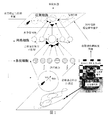
- the nodes on the final navigation map contain location cell group coding information, corresponding visual cues and location topological relationships. The overall schematic is shown in Figure 1.
- the data input portion that implements the method is primarily self-motion cues and visual image information. It is realized by photoelectric encoder, gyroscope and RGB-D sensor.
- the photoelectric encoder collects the speed signal
- the gyroscope collects the angle signal
- the RGB-D sensor collects the color and depth image.
- the central processor is used for the calculation and processing of the cognitive map generation algorithm, and the motor control generates a motor control signal to control the robot motion.
- Step (1) At the initial moment, the robot's head direction is set to zero, and the current instantaneous speed and angle information is obtained by its own photoelectric encoder and gyroscope. At the same time, Kinect performs at a speed of two frames per second. graphic gathering.
- Step (2) Based on the linear velocity integral of the striped cells.
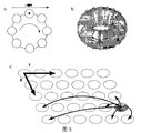
- a schematic diagram of a one-dimensional annular attractor model of striped cells is shown as a in Figure 5.
- the robot obtains the angle information and the line speed information of the motion through its own gyroscope and photoelectric encoder, and the robot moves along the direction at time t.
- the moving speed is ⁇ (t)
- the velocity v ⁇ (t) and the displacement D ⁇ (t) along the direction ⁇ are:
- the directional displacement is converted into the activity of a plurality of striped cells along the preferential direction ⁇ , and the discharge rate x ⁇ of the striped cells represents the phase ⁇ , and the striped cell phase is ⁇ .
- the striped cell has a discharge period of l.
- the striped cell has the maximum discharge rate at the position nl+ ⁇ (n is an integer) in the preferential direction of the periodic direction. Then, the distance of the periodic discharge reset of the striped cell represents ⁇ ⁇ (t) is the space between D ⁇ and ⁇ .
- the phase difference is:
- the discharge rate of striped cells is expressed as:
- ⁇ s is the standard deviation, describing the width of the stripe field along the preferential direction.
- Stripe cells that span multiples of the periodic position will be co-excited, encoding spatially specific displacements, as forward input information for the grid cells, driving the grid cell attractors to move in a plane.
- Step (3) The grid cell attractor model of the two-dimensional continuous space periodically performs position coding.
- the attractor plane is also known as the neural plate.
- the two-dimensional annular attractor model of the grid cells is shown as b in Figure 5.
- the kinetic formula for the discharge rate of grid cells is:
- ⁇ is the time constant of the neuron
- the neuron transfer function f[ ⁇ ] is a simple nonlinear rectification function.
- the discharge rate of the current position neuron i is s i , Is the weight of the connection of neuron j to neuron i in the neural plate, Inhibition recursion is projected onto the input of neuron i, B i from antegrade excitatory input streak cells.
- Each grid cell neuron i has a preferential direction ⁇ i , which is determined by the projection of the striped cells.
- the grid cells receive the forward projection from the striped cells, and the preferential orientation information in the forward projection is used to determine the direction of change of the output weight and determine the speed input information it receives from the robot.
- Step (4) a grid-to-location cell-competitive network generates a spatially specific location code
- the grid cells serve as the source of input information for the location cells, and the discharge activity of the location cells is the output of the path integration system.
- the discharge activity of the location cells is the output of the path integration system.
- a competitive heb learning algorithm is used to find a subset of grid cell family activities, and the location cell family activity is calculated.
- Equation (9) determines the direction of weight change: if the current grid cell activation rate is greater than the incoming average activation rate, synaptic connections are enhanced; otherwise, synaptic connections are inhibited. Setting It is ensured that the weight is not a negative value, and therefore, the weight through the equation (9) is suppressed.
- the spatial selectivity of a location cell to a given location results from the selective binding of grid cell activity with multiple spatial phase and spatial spacing jointly encoded for that location. Therefore, a plurality of spatially spaced and oriented grid cells are required, as well as a plurality of spatially spaced and oriented striped cells.
- Each neural plate represents a grid cell family activity. This method produces a plurality of grid cell families of different scales by uniformly sampling a and ⁇ net . Equation (9) detects grid cell population activity from spatial overlap of multilayer neural plates.
- the family activity of the location cells is derived from the projection information of the grid cells:
- a and C inh are the gain and inhibition constants of the positional cell network, respectively, and M is the number of layers of the grid cell neural plate.
- C inh is used to control the number of cells in the positional cell, as determined by B*max(p i (r)).
- Step (5) Iterative update of path integration of positional cells
- the positional cell attractor model constructs a metric model of the relative position of the actual external environment, the attractor model neural plate being as shown by c in Figure 5.
- the two-dimensional continuous attractor model forms a random activity bump on a neural plate from local excitability, inhibitory connections, and global inhibitory connections. This attractor is driven by the spatial cell pathway integration system.
- Step (5-1) acquires the relative position of the current position point.
- a two-dimensional Gaussian distribution is used to create an excitability weight connection matrix ⁇ m,n for the location cells, where the subscript m,n represents the distance between the horizontal and vertical coordinates of the cell in the coordinate system X and Y.
- the weight distribution can be expressed as:
- k p is the width constant of the position distribution.
- n X and n Y are the size of the two-dimensional matrix of the positional cells in the (X, Y) space, representing the extent to which the attractor model is active on the neural plate. Because of the borderless nature of the cells in the network, as shown in Figure 5c, the cells at the position of the neural plate boundary will have excitatory connections with the cells at the opposite boundary, and the premise of position cell iteration and visual template matching is to find the location cells.
- the relative position of the attractor in the neural plate. This relative position coordinate is represented by the subscript of the weight matrix and is calculated by the following formula:
- n (Yj)(mod n Y ) (13b)
- Each location cell also receives a global suppression signal for the entire network. Unlike the Mexican hat attractor model formed by grid cells, the inhibition signal of the location cells occurs after the local excitatory junction, rather than simultaneously.
- the symmetry of the excitatory and inhibitory connection matrix guarantees proper neural network dynamics, ensuring that the attractors in the space are not unrestricted.
- the amount of activity change in a location cell caused by an inhibitory connection weight is:
- the activation rate of the location cells is compared to zero:
- the activity rate of the location cells is then normalized.
- the positional cell attractor moves from the spatial cell's path integral to the self-moving cues
- the striped cell encodes a displacement in a particular direction
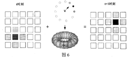
- the mesh attractor pairs a particular direction The two-dimensional space above is encoded so that different grid cell families are activated. A subset of different grid cell family activities determines the movement of the position attractor. A schematic of this process is shown in Figure 6.
- ⁇ X 0 and ⁇ Y 0 are the offsets of the rounding down in the XY coordinate system, and the offset is determined by the velocity and direction information.
- the residual amount is a piecewise function of the residual offset:
- ⁇ mn g ( ⁇ X f, m- ⁇ X 0) g ( ⁇ Y f, n- ⁇ Y 0) (20)
- Step (5-3) view template matching
- the cognitive map generated only by the path integration mechanism has large errors in a large space and cannot form an accurate cognitive map.
- This method uses kinect to collect RGB maps and depth maps in the environment for closed-loop detection.
- the RGB-D image is used as a visual cue to correct the path integral error and reset the navigation cell family activity.
- the illumination changes, the RGB image is affected, while the depth map is not affected by the illumination.
- the comparison of the depth map and the RGB image enables closed-loop detection and recognition of new scenes.
- the view template matching algorithm uses the scan line intensity distribution in the color and depth images (scanline) Intensity profile).
- the scan line intensity distribution is a one-dimensional vector, which is the result of summing the strengths of all the columns of the grayscale image and normalizing them.
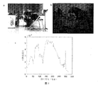
- the scan line intensity distribution map of a pair of images, a and b in FIG. 7 are a color map and a depth map, respectively.
- the scan line intensity distribution of the image acquired by the robot during the exploration process is stored as a partial view template, and the scan line intensity distribution of the current image is compared with the previously stored partial view template. If it can be matched, it is considered that a closed loop is found, if If it cannot be matched, it will be stored as a new view template.
- the current image distribution is compared to the view template by using an average absolute intensity difference function.
- the average absolute intensity difference between the intensity distributions of the two image scan lines is also called the intensity offset, which is represented by g(c):
- I j and I k are the scan line intensity distributions of the compared images
- c is the amount of profile shift
- b is the width of the image.
- the present invention adopts a method in which the two images of the color map and the depth map are simultaneously matched to determine the absolute position, due to the actual space.
- the illumination intensity of the environment is different in different time periods, and the difference between the offsets of the color map and the depth map is given different weights, and the matching degree measure G of the image can be obtained:
- the minimum offset c m of I j and I k pixels in successive images is the minimum of the matching metric G for the two images.
- the offset ⁇ ensures that there is an overlap between the two images.
- Set the comparison threshold of the image to c t .
- the current view is a new view and save it in the visual template set ⁇ V i ⁇ .
- c m ⁇ c t it is considered to be back to a repetition. Scene.
- the cognitive map constructed by the method establishes a topological relationship between the positions of the cell discharge activities, and is composed of empirical points e having a topological relationship, and the topological relationship between the experience points is represented by t ij .
- Each experience point contains the current site location cell discharge activity p i , visual template V i .
- the position of a single experience point is represented by p i .
- a single experience point is defined as:
- the current position can be compared to the position in the existing experience point to get a position metric D:
- the location point of the current experience point exceeds the experience threshold or when a new visual template is found, a new point of experience is created.
- the conversion amount t ij stores the position change amount calculated by the path integral, that is:
- Step (6-2) Experience map update at closed loop
- the robot When the view template detects the actual closed-loop point, the robot returns to the same position, but the new experience of the accumulated amount of position variables at the closed loop does not match this same position, in order to achieve the match between the two. All the experience needs to be updated in the closed loop:
- N f is the number of transitions from experience e i to other experiences
- N t is the number of transitions from other experience to experience e i .
- the robot When the robot detects a closed loop point through view template matching, it resets the discharge rate of the space cell to the previous active state.
- Figure 1 is a schematic diagram of the overall algorithm of the present invention
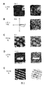
- Fig. 2 is a graph showing the spatial cell discharge rate of the present invention.
- the left graph in A, C, and D is the discharge rate map, and the left graph in B indicates the polar map of the direction cell, in which the cell has the highest discharge rate in the southeast direction;
- the figure is a plot of the trace discharge rate.
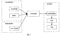
- Figure 3 is a schematic diagram of information transfer and model of spatial cells involved in the present invention
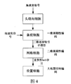
- FIG. 4 is a hardware structure diagram of the present invention
- Figure 5 is a schematic diagram of a spatial cellular attractor model of the present invention, wherein a is a one-dimensional annular attractor model of striped cells, b is a two-dimensional annular attractor model of grid cells, and c is a circular attractor of positional cells.
- a is a one-dimensional annular attractor model of striped cells
- b is a two-dimensional annular attractor model of grid cells
- c is a circular attractor of positional cells.
- Figure 6 is a schematic diagram showing the integration of positional cell pathways of the present invention.
- the black point is the middle position of the position cell attractor. With the movement of the mesh cell attractor, the position cell attractor performs path integration.
- a is a color map acquired by Kinect
- b is a corresponding depth map
- c is a scan line intensity distribution corresponding to the color map.
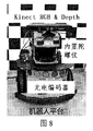
- FIG. 8 illustrates the robot platform used in the present invention
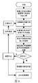
- Figure 9 is an overall algorithm flow chart of the present invention.
- Figure 10 shows a laboratory environment of 2 m * 2 m in Example 1.
- the red line is the real motion track of the robot
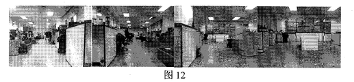
- Figure 12 is a multi-color picture captured in a 3m*10m laboratory environment surrounded by multiple similar color maps in Example 2.
- FIG. 13 is a top view scan view of a 3 m*10 m laboratory environment track of the present invention in Example 2, and the blue track is the actual track of the robot.
- Figure 14 is a map construction process of the present invention in Embodiment 2
- Figure 15 is a closed loop detection and space cell discharge reset process of the present invention in Embodiment 2
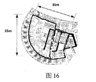
- Figure 16 is a top view scan of a circular building with a radius of 35 m in the embodiment 3, wherein the blue point shows the true trajectory point of the robot
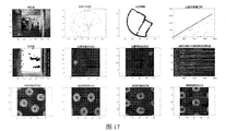
- Figure 17 is a diagram showing the elements of the cognitive map generated by the robot at 1050s in the third embodiment of the present invention.
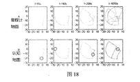
- Figure 18 is a comparison diagram of the path integral map and the cognitive map of the present invention in the third embodiment
- the robot navigation map construction method based on rat brain hippocampus space cell proposed by the invention is to utilize a small number of sensors to obtain a universal and accurate robot navigation map by using a bionic method, and solve the traditional problem.
- the SLAM algorithm has high requirements on sensors and hardware, high computational complexity, limited accuracy, and low adaptability.
- the mobile unit consists of two front wheels and one rear wheel.
- the rear wheel is a small universal wheel that facilitates stable support and disguise of the robot.
- the front wheel is equipped with a photoelectric encoder that captures and records the movement speed of the robot.
- the built-in gyroscope captures the direction of movement of the robot.
- the Kinect is placed above the platform panel and powered by the inverter to capture RGB-D images as the robot moves.
- the Kinect is directly connected to the control PC and takes one RGB and DEPTH image at a rate of two frames per second.
- the entire platform communicates with the robot through the USB port.
- the maximum moving speed of the mobile robot platform is set to 0.5m/s.
- the number of heads facing the cells is set to 360, and ⁇ net is a uniformly distributed sample with an interval of 1 from 12 to 52.
- Set the stripe cell's stripe orientation to ⁇ i [0° 90° 180° 270°].
- the cells at the boundary are connected to cells at opposite boundaries. As shown in Fig. 5b, the neural plate forms a torus, and the hexagonal mesh field is produced by a twisted ring.
- the position of the neuron i is among them,
- the distance between neurons on the neural cells of a grid cell is called the induced metric, expressed as dist(.,.).
- this is the Eulerian paradigm, which is calculated as:
- offset j is the offset amount set to achieve the twisted ring, and its specific value is: ⁇ is the Eulerian paradigm.
- the first step, data collection uses a computer to control the movement of the robot in the environment, collecting speed, direction, and image information at that location.
- the sampling period is 500ms.
- the second step is the path integration of the spatial cells.
- Schematic diagram of three spatial cell attractor models as shown in Figure 5 at time t The moving speed is ⁇ (t), then the velocity v ⁇ (t) and the displacement D ⁇ (t) along the direction ⁇ are:
- the directional displacement is converted into a motion of the fringe cell family along the preferential direction ⁇ , and the discharge rate x ⁇ of the striped cell represents the phase ⁇ , and the streak cell phase is ⁇ .
- the striped cell has a discharge period of l.
- the stripe cells have a maximum discharge rate at the position nl+ ⁇ (n is an integer) at the periodic direction of the preferential direction, and the discharge rate is expressed as:
- the stripe cell discharge rate forward projection drives the grid cell attractor to periodically encode the environment.
- the weighted connections of the grid cells form the attractors of the grid cells:
- the discharge rate of the grid cells is determined by the recursive connection and the forward projection:
- the grid cells generate a code for the specific location of the location cells by the competitive Heb learning network.
- a competitive heb learning is used to determine a subset of grid cell family activities that generate location cell release fields.
- the family activity of the location cells is derived from the projection information of the grid cells:
- a and C inh are the gain and inhibition constants of the positional cell network, respectively, and M is the number of layers of the grid cell neural plate.
- C inh is used to control the number of cells in the positional cell, as determined by B*max(p i (r)).
- Step 5 Determine the discharge rate and discharge position of the positional cells in the attractor plane
- the positional cell attractor model constructs a metric model of the relative position of the actual external environment.
- the two-dimensional continuous attractor model forms a random activity bump on a neural plate from local excitability, inhibitory connections, and global inhibitory connections. This attractor is driven by the spatial cell path integration system, from the current location. The image information is reset.
- the activity package is shown by the gray neurons in Fig. 5c, similar to the annular attractor model of the grid cells, and the cells at the boundary of the network are connected to the cells at the other boundary to form a ring.
- a two-dimensional Gaussian distribution is used to create the excitability weight connection matrix ⁇ m,n of the positional cells, where the subscripts m, n represent the distance between the horizontal and vertical coordinates of the unit in the coordinate system X and Y.
- the weight distribution can be expressed as:
- k p is the width constant of the position distribution.
- n X and n Y are the size of the two-dimensional matrix of the positional cells in the (X, Y) space, representing the extent to which the attractor model is active on the neural plate. Because of the borderless nature of the cells in the network, as shown in Figure 5c, the cells at the position of the neural plate boundary will have excitatory connections with the cells at the opposite boundary, and the premise of position cell iteration and visual template matching is to find the location cells.
- the relative position of the attractor in the neural plate. This relative position coordinate is represented by the subscript of the weight matrix and can be calculated by the following formula:
- n (Yj)(mod n Y )
- Each location cell also receives a global suppression signal for the entire network. Unlike the Mexican hat attractor model formed by grid cells, the inhibition signal of the location cells occurs after the local excitatory junction, rather than simultaneously.
- the symmetry of the excitatory and inhibitory connection matrix guarantees proper neural network dynamics, ensuring that the attractors in the space are not unrestricted.
- the amount of activity change in a location cell caused by an inhibitory connection weight is:
- the activity rate of the location cells is then normalized.
- the positional update of the positional cells is driven by the path integral of the upstream cortical space cells.
- the discharge rate of the path integral attractor at the next moment is determined by the combination of the offset amount and the positional cell attractor discharge rate at the current time. As shown in Figure 6. Then the discharge rate of the cells at the next moment Can be expressed as:
- ⁇ X 0 and ⁇ Y 0 are the offsets of the rounding down in the XY coordinate system, and the offset is determined by the velocity and direction information.
- the residual amount is a piecewise function of the residual offset:
- ⁇ mn g ( ⁇ X f, m- ⁇ X 0) g ( ⁇ Y f, n- ⁇ Y 0)
- the seventh step is the matching and construction of the view template of the current location point.
- the robot acquires the color and depth image through the Kinect at the current site, calculates the scan line intensity distribution of the current site image, first converts the color image into a grayscale image, and then sums the intensity of all the columns of the grayscale image and normalizes it. .
- the scan line intensity distribution map of a pair of images, 7a and b are respectively a color map and a depth map.
- the image scan line intensity distribution acquired by the robot during the entire exploration process is stored as a partial view template, and the scan line intensity distribution of the current image is compared with the previously stored partial view template to determine whether it has returned to a position that has been previously.
- the current image distribution is compared to the view template by using an average absolute intensity difference function.
- the average absolute intensity difference between the intensity distributions of the two image scan lines is also called the intensity offset, which is represented by g(c):
- I j and I k are compared to the scan line intensity distribution of the image
- c is the distribution offset
- b is the width of the image
- the present invention adopts a method in which the two images of the color map and the depth map are simultaneously matched to determine the absolute position, due to the actual space.
- the ambient light intensity varies in different time periods, for color maps and
- the difference between the offsets of the depth maps gives different weights, and the matching measure G of the image can be obtained:
- G ⁇ R
- the minimum offset c m of I j and I k pixels in successive images is the minimum of the matching metric G for the two images.
- the offset ⁇ ensures that there is an overlap between the two images.
- Set the comparison threshold of the image to c t .
- c m ⁇ c t the image does not match.
- the current view is set to a new view and saved in the visual template set ⁇ V i ⁇ .
- c m ⁇ c t Then think back to a repeated scene.
- the eighth step is the construction of cognitive maps.
- the cognitive map constructed by the present invention establishes a topological relationship between positions of cell discharge activities, and is composed of empirical points e having a topological relationship, and the topological relationship between the experience points is represented by t ij .
- Each experience point contains the current site location cell discharge activity p i , visual template V i .
- the position of a single experience point is represented by p i .
- the experience points can be expressed as:
- the current position can be compared to the position in the existing experience point to get a position metric D:
- the location point of the current experience point exceeds the experience threshold or when a new visual template is found, a new point of experience is created.
- the robot explores the environment, it gradually builds up the experience points of the environment.
- the conversion amount t ij stores the position change amount calculated by the path integral, that is:
- t ij forms the connection between previous experience and new experience points.
- the topology connection of the experience points remains unchanged during the generation of the experience points and changes during the closed loop detection.
- Step IX the experience map update at the closed loop
- the robot When the view template detects the actual closed-loop point, the robot returns to the same position, but the new experience of the accumulated amount of position variables at the closed loop does not match this same position, in order to achieve the match between the two. All the experience needs to be updated in the closed loop:
- N f is the number of transitions from experience e i to other experiences
- N t is the number of transitions from other experience to experience e i .
- Embodiment Scenario 1 The robot is allowed to continue to walk 8 words 399s in a 2 m*2 m environment in a laboratory environment.
- the experimental scene is shown in Figure 10.
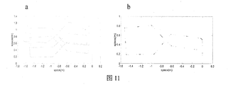
- FIG. 1 A map of the resulting path integral map and position cell discharge rate expression is shown in FIG. It can be seen that the path integral map can not correctly express the environment passed, and the generated position cell discharge rate map can reflect the environment passing through. This illustrates the reliability of the present invention in generating maps in repeated spatial motions.
- Embodiment Scenario 2 The scene is a 3m*10m environment surrounded by multiple similar color maps (as shown in Figure 12), and the robot moves from 16s around the environment to 170s until the end of the exploration process.
- Fig. 13 is a view showing the actual environment of the embodiment 2 as shown in Fig. 13.
- the cognitive map rendering of the final construction of the model is shown in the second row and third column of Figure 14.
- the process of constructing a map is as shown in FIG.
- the first line shows the odometer map collected by the robot
- the second line shows the process of constructing the cognitive map according to the method of the present invention. It can be seen that when no closed loop point is detected, the odometer map and the cognitive map are displayed. There is no difference. The closed-loop point of the environment was detected at 89s, and the cognitive map was adjusted at 89.5s. Over time, the odometer map error became larger and larger, and the cognitive map was closed-loop detected. The more consistent the actual activity track.
- the process of closed-loop detection and spatial cell discharge reset is shown in Figure 15.
- the first behavior is the cognitive map and the positional cell discharge rate at 7.5 s.
- the closed loop point of the environment is detected (shown in the second row).
- the model performs the adjustment of the cognitive map (shown in the third row) and performs the discharge rate reset.
- the position cell family discharge activity and the cognitive map point in Figure 15 (the first column circle in the figure)
- the results shown are not exactly the same, because the positional cell family activity expresses the relative position of the robot in the environment.
- the above experimental results verify the effectiveness of the method of the present invention in an confusing environment.
- Embodiment Scenario 3 In order to verify the reliability of the present invention in generating a precise cognitive map of a large-scale complex environment, a circular office building having a radius of 35 m is explored by the method of the present invention, and the top view of the ring building is as shown in FIG. Shown.
- the robot in Fig. 8 was continuously explored in the ring building using the method of Fig. 9 for 1050 s; the trajectory of its exploration is shown by the blue line in Fig. 16. As shown in FIG. 17, comparing the path integral map with the finally generated cognitive map, the path integral map cannot accurately describe the map of the current environment, and the cognitive map is an accurate description of the environment.
- Figure 18 is a process of evolution of a path integral map and a cognitive map.
- the evolution process of cognitive maps over time, 18A is the original odometer map
- Embodiments 1, 2, and 3 verify that the present invention has good universality and effectiveness, and is capable of generating cognitive maps with different environments.
Landscapes
- Engineering & Computer Science (AREA)
- Physics & Mathematics (AREA)
- Radar, Positioning & Navigation (AREA)
- General Physics & Mathematics (AREA)
- Automation & Control Theory (AREA)
- Remote Sensing (AREA)
- Aviation & Aerospace Engineering (AREA)
- Artificial Intelligence (AREA)
- Evolutionary Computation (AREA)
- Computer Vision & Pattern Recognition (AREA)
- Electromagnetism (AREA)
- Software Systems (AREA)
- Medical Informatics (AREA)
- Health & Medical Sciences (AREA)
- Robotics (AREA)
- Mechanical Engineering (AREA)
- Optics & Photonics (AREA)
- Multimedia (AREA)
- Image Analysis (AREA)
- Manipulator (AREA)
- Feedback Control In General (AREA)
Abstract
一种基于鼠脑海马空间细胞的机器人导航地图构建方法,根据哺乳动物海马结构中的空间导航相关细胞的信息传递回路,机器人通过对环境探索,获取当前的自运动线索和颜色深度图像信息,自运动线索经由海马结构中空间细胞的路径积分和特征提取,渐进的形成对空间环境的编码,位置细胞的位置野在探索过程中逐渐形成,并覆盖整个空间环境,形成认知地图,与此同时,Kinect采集当前位置正前方视图场景的颜色深度图像信息作为绝对参考,进行路径的闭环检测,纠正路径积分的误差。在闭环点处,系统进行空间细胞放电活动的重置,对路径积分误差进行修正。最终的导航地图上的节点包含的是位置细胞群编码信息、对应的视觉线索以及位置拓扑关系。
Description
本发明涉及一种基于鼠脑海马空间细胞的机器人导航地图构建方法。根据哺乳动物海马结构中有着导航相关特性的空间细胞的特点制定自主移动机器人自主导航地图构建方法。用于多尺度和复杂环境下机器人的导航地图构建。
现阶段的环境地图构建方法,大多是依据SLAM方法构建地图,如栅格地图和拓扑地图法,依据广角摄像头提取环境特征点构建地图,对视觉信号和图像的处理算法以及硬件性能均提出了很高要求,而栅格的划分,拓扑点的募集大多数属于人为设定,只能面向于特定的静态环境,可扩展性程度不高。随着当前运动环境的不断复杂,特别在动态的环境中,单一导航方式已不能满足现实需求,多导航策略能够将若干种导航手段优势互补,达到更好的效果,其常用的数据融合方式是卡尔曼滤波算法,但是,应用卡尔曼滤波算法需要精确构建系统的运动模型和观测模型,而对复杂动态环境的建模,计算复杂,限制了卡尔曼滤波器的应用。
依据生物认知环境的机理,使机器人能够更加智能化的构建环境的认知地图,能够克服现阶段环境地图构建方法的诸多缺陷。哺乳动物(如:老鼠、人等)在空间环境中有目的的移动需要对空间环境进行编码,需要对多种传感信息进行内在的融合,形成内在的神经表达,这种内在的神经表达被称为认知地图。对空间环境的进行认知并海马结构中与认知地图构成相关的空间导航细胞主要有:头朝向细胞、条纹细胞、网格细胞、边界细胞和位置细胞。
研究发现,海马体是动物环境认知的关键脑区。1971年,O’Keefe和Dostrovsky发现海马体中的CA1和CA3区的椎体神经元只在空间的特定位置放电,当动物处于一个特定的空间位置时,椎体细胞放电频率最大,当动物远离这一位置时,放电频率下降,这些神经元被称为位置细胞(Place cell),其放电活动对应的动物在环境中的活动范围被称为位置野(Place field)。位置细胞的选择性放电的特性形成了大脑和外界空间位置的映射关系,是动物进行自我定位和空
间环境认知的重要元素。具体而言,位置细胞有如下特性:
位置细胞的位置野在动物进入新的环境中会迅速生成并随着对环境的遍历而覆盖整个环境;
相同的位置细胞可能在不同的环境发放,有着不同的位置野;
与视觉皮层上的神经细胞不同,位置细胞本身在脑中的相对位置与对应的位置野并无直接联系,换言之,两个相邻的位置细胞可能所对应的实际地理的位置野并不相邻;
外源性信息(如:视觉、嗅觉等)和内源性信息(如:前庭信息、躯体感觉)都能使位置细胞发放,并形成稳定的位置野,在没有外源性信息输入情况下(如:黑暗环境)位置细胞也能发放并形成稳定的位置野。
1990年,Taube等人在后下托中发现了一种头方向依赖的神经元,当动物的头部面向特定方向时,这种神经元发生最大放电,被称为头朝向细胞(head direction cell),头朝向细胞是一种头朝向依赖性神经元,放电活动只与头在水平面的朝向有关,与动物的位置、姿势、行为无关。每个头朝向细胞有且只有一个最佳朝向,在一个不变的环境中,头朝向细胞保持长时间的稳定性。可表示成一个高斯模型;
2005年Hafting等人通过变换试验箱的大小和形状,发现了对空间具体位置具有强烈放电的网格细胞(grid cell),当老鼠在二维空间中活动时,网格细胞在特定的位置发生重复性规律放电,这个空间范围称为网格细胞的网格野(grid field),网格细胞多个放电区域相连形成的三角形激活域遍布老鼠经过的整个空间环境。网格节点的间距在39-73厘米之间变化,沿着内嗅皮质的背腹侧轴网格放电野的间距逐渐增大,不同环境中同一个网格细胞的激活域一般不同,当老鼠处于黑暗环境时,网格域也能保持稳定;每个网格细胞形成的网格都具备4个基本特征:①间距(spacing):各放电野中心之间的距离;②定向(orientation):相对于外在参考坐标的倾斜度;③位相(phase)相对于外部参考点的x轴和y轴位移;④放电野大小(firing field):网格细胞发生放电的空间范围。这4个成分构成了网格图的空间参数。
2012年,O’Keefe等人证实在旁下托和内嗅皮层中发现了有空间周期性条纹状的放电野的细胞存在,被称为条纹细胞(stripe cells),其放电野类似于平行的
条纹状覆盖在整个空间环境中。条纹细胞被认为是完成路径积分的基础机制,其放电活动能够由四个特征表征:①条纹间距(stripe spacing):条纹放电野中心之间的距离;②条纹野宽度(stripe field width):放电野的横向空间放电的范围;③条纹相位(stripe phase)相对于外部参考点的位移;④优先方向(preferred direction):条纹野固有的相对于外在参考坐标的倾斜度。
五种空间细胞的激活率图如附图2所示
头朝向细胞位于前下托,编码头朝向信息,投射到内嗅皮层的浅皮层中的条纹细胞,内嗅皮层中的条纹细胞作为网格细胞的输入,对线速度信息进行编码,网格细胞能够对条纹细胞的输入信息进行路径积分,通过特征提取,生成特定位置编码的位置细胞位置野。而位置野是构成认知地图的基本要素。
海马已被认为是脑内再现空间环境的认知地图的结构,海马的位置细胞、内嗅皮层的网格细胞和边界细胞、存在于多个脑区的头朝向细胞,以及新发现的条纹细胞和各种感觉系统,共同组成了大脑内部的空间导航系统。
使用连续的吸引子模型模拟网格细胞的放电现象与内源性信息的路径积分,空间细胞的活动来源于吸引子神经网络活动的集体行为,网络活动的最终状态是在低维流型上连续的稳定状态,这些最终稳定状态就是吸引子,而在流型平面上吸引子位置的调节与更新源于对老鼠运动速度的响应。
本方法依据鼠脑海马结构空间细胞结合Kinect采集的颜色深度图进行机器人导航地图的构建,空间细胞计算模型采用吸引子模型。本发明相比于传统的SLAM导航方法,对硬件和传感器要求低,具有良好的可扩展性和适应性,所采用的数据融合处理方法相对于传统的卡尔曼滤波方法具有较低的计算成本,能够高效而准确的完成对室内外环境的地图构建。
发明内容
本发明根据动物海马解剖学结构和空间导航细胞的神经生理学特性,提出了一种基于空间细胞作用机理的环境导航地图构建方法。根据哺乳动物海马结构中的空间导航相关细胞的信息传递回路,如附图3所示,机器人通过对环境探索,获取当前的自运动线索和颜色深度图像信息,自运动线索经由海马结构中空间细胞的路径积分和特征提取,渐进的形成对空间环境的编码,位置细胞的位置野在
探索过程中逐渐形成,并覆盖整个空间环境,形成认知地图,与此同时,Kinect采集当前位置正前方视图场景的颜色深度图像信息作为绝对参考,进行路径的闭环检测,纠正路径积分的误差。在闭环点处,系统进行空间细胞放电活动的重置,对路径积分误差进行修正。最终的导航地图上的节点包含的是位置细胞群编码信息、对应的视觉线索以及位置拓扑关系,整体的示意图如附图1所示。
为了达到以上目的,本发明采用如下技术方案实现:
一种基于鼠脑海马空间细胞的机器人导航地图构建方法,整体的硬件系统图如附图4所示。实现该方法的数据输入部分主要是自运动线索和视觉图像信息。通过光电编码器、陀螺仪、RGB-D传感器实现。光电编码器采集速度信号,陀螺仪采集角度信号,RGB-D传感器采集颜色和深度图像。中央处理器用于对认知地图生成算法的计算和处理,通过电机驱动产生电机控制信号,控制机器人运动。
基于海马空间细胞的机器人导航地图构建算法,整体算法流程图如附图3所示。
步骤(1):机器人在初始时刻,静止的头方向设置为零,通过其自带的光电编码器、陀螺仪获取当前的瞬时速度和角度信息,与此同时Kinect以每秒两帧的速度进行图像采集。
步骤(2):基于条纹细胞的线速度积分。
条纹细胞的一维环状吸引子模型示意图如附图5中的a所示。机器人通过自带的陀螺仪和光电编码器获取运动的角度信息和线速度信息,在t时刻机器人沿着方向 移动速度是ν(t),那么沿着方向θ的速度vθ(t)和位移Dθ(t)分别为:


方向位移被转换成多个条纹细胞沿着优先方向θ的活动,条纹细胞的放电率xθα代表沿着方向θ,条纹细胞相位为α。条纹细胞放电周期为l。在优先方向周期性的位置nl+α(n为整数)上条纹细胞有着最大放电率,那么,条纹细胞周期性放电重置的距离代表了ωθα(t)为Dθ和α之间的空间相位差为:
ωθα(t)=(dθ(t)-α)mod l (3)
条纹细胞的放电率表示为:

其中,σs是标准差,描述了条纹野沿着优先方向的宽度。
跨越周期性位置的倍数的条纹细胞将会共同激发,编码了空间特定方向的位移,作为网格细胞的前向输入信息,驱动网格细胞吸引子在平面上运动。
步骤(3):二维连续空间的网格细胞吸引子模型周期性的进行位置编码。
网格细胞间存在着递归连接,权值的相互作用形成了网格细胞在空间特定位置的吸引子,吸引子呈六边形分布。与此同时来自于条纹细胞的前向输入驱动网格细胞吸引子在平面上运动,对整个平面进行周期性特征编码。吸引子平面又称为神经板。网格细胞的二维环状吸引子模型如附图5中的b所示。
网格细胞的放电率的动力学公式为:

其中,τ是神经元相应的时间常量,神经元传递函数f[·]是一个简单的非线性整流函数,当x>0时,f(x)=x,当x≤0时,f(x)=0。当前位置神经元i的放电率为si, 是在该神经板中神经元j到神经元i的连接权值,
 是投射到神经元i的抑制性递归输入,Bi是来自于条纹细胞的前向性兴奋性输入。每个网格细胞神经元i都有着一个优先方向θi,这个优先方向信息由条纹细胞的投射确定。
网格细胞接收来自于条纹细胞的前向投射,前向投射中的优先朝向信息,被用于确定输出权值的改变方向,并确定其接收到机器人的速度输入信息。
Bi=ωθα(t) (6)
网格细胞之间存在递归连接,其递归连接权值为:

其中,

权值矩阵形成一个中间高两边低的墨西哥帽形状分布,其中间位置为 在所有的参数设定中,
 其中λnet是神经片上形成网格的周期,由条纹细胞的周期l确定。当a=1时,所有的连接都是抑制性的,局部周围抑制性连接足够产生网格细胞响应。
步骤(4):网格细胞到位置细胞的竞争型网络产生空间特定位置的编码
网格细胞作为位置细胞的输入信息来源,位置细胞的放电活动是路径积分系统的输出。为了产生位置细胞族的单峰型放电野,需要学习网格细胞族到位置细胞突触权值分布,确定在单个位置有着重叠活动包的网格细胞族的激活比例。
采用竞争性heb学习算法寻找网格细胞族活动的子集,计算位置细胞族活动。

其中,k为学习率,pi为位置细胞的放电率,sj为网格细胞的放电率,<·>为网格细胞的平均放电率。式(9)的右边确定权重变化的方向:如果当前网格细胞激活率大于传入的平均激活率,突触连接增强;否则,突触连接发生抑制。设置 确保权值不为负值,因此,通过式(9)的权值被抑制。
位置细胞的对给定位置的空间选择性来源于对该位置联合编码的具有多个空间相位和空间间距的网格细胞活动的选择性结合。因此,需要多个空间间距和朝向的网格细胞,同样需要有多个空间间距和朝向的条纹细胞。每个神经板代表了一个网格细胞族活动,本方法通过对a和λnet进行均匀采样产生多个不同尺度的网格细胞族。式(9)从多层神经板的空间重合检测网格细胞群体活动。
位置细胞的族活动来源于网格细胞的投射信息:

其中,A和Cinh分别为位置细胞网络的增益和抑制常量,M是网格细胞神经板的层数, 是网格细胞族j到位置细胞族i的突触连接权值,r是当前动物的位置。Cinh用来控制位置细胞放电野的个数,由B*max(pi(r))确定。通过上述的竞争性算法,确保了只有少量的网格细胞族的子集被选择形成位置细胞的单一型放点野。
步骤(5):位置细胞的路径积分的迭代更新
位置细胞吸引子模型构建了对于实际外界环境相对位置的度量模型,其吸引子模型神经板如附图5中的c所示。二维连续吸引子模型由局部兴奋性、抑制连接和全局抑制性连接在一个神经板上形成一个随机的活动包(activity bump),这个吸引子由空间细胞路径积分系统驱动。
步骤(5-1)获取当前位置点的相对位置。
一个二维的高斯分布被用于创建位置细胞的兴奋性权值连接矩阵εm,n,其中下标m,n代表在坐标系X和Y中所属单元横纵坐标之间的距离。权值分布可表示为:

其中,kp为位置分布的宽度常量。
由于局部兴奋性连接导致的位置细胞活动的变化量为:

其中,nX、nY是在(X,Y)空间中位置细胞二维矩阵的大小,代表着吸引子模型在神经板上活动的范围。因为网络中位置细胞的无边界性,如图5c所示,处于神经板边界的位置细胞会与相对边界的位置细胞产生兴奋性连接,而进行位置细胞迭代和视觉模板匹配的前提是查找位置细胞吸引子在神经板中的相对位置,这个相对位置坐标由权值矩阵的下标表示,由下式计算得到:
m=(X-i)(mod nX) (13a)
n=(Y-j)(mod nY) (13b)
每个位置细胞同样接收着整个网络的全局性抑制信号。与网格细胞所形成的墨西哥帽吸引子模型不同,位置细胞的抑制信号发生在局部性兴奋连接之后,而不是同时起作用。兴奋性和抑制性连接矩阵的对称性保证了合适的神经网络动力学,确保空间中的吸引子不会无限制的兴奋。位置细胞由抑制性连接权值引起的活动变化量为:

其中,ψm,n是抑制性连接权值, 控制全局性的抑制水平。
为确保t+1时刻的所有位置细胞的活动都是不小于零的,将位置细胞的激活率与0进行比较:

随后将位置细胞的活动率进行归一化。

步骤(5-2)位置细胞的路径积分
在本方法中,位置细胞吸引子的移动来自于空间细胞的对自运动线索的路径积分,条纹细胞编码了特定方向上的位移,驱动网格细胞吸引子的移动,网格吸引子对特定方向上的二维空间进行编码,使得不同的网格细胞族激活。不同的网格细胞族活动的子集确定了位置吸引子的移动。这一过程的示意图如附图6所示。
路径积分后位置细胞的放电率 表示为:
表示为:

其中,δX0、δY0是X-Y坐标系中向下取整的偏置量,这一偏置量由速度和方向信息确定,

其中,[·]表示向下取整,km、kn是路径积分常量, 是指向θi的单位向量,θ为当前头朝向,下一时刻位置细胞的活动率由当前时刻位置细胞的活动率与残差量αmn的乘积,残差量是位置细胞活动包的扩散作用的量化,这个扩散作用可由残差偏置量表示,源于网格细胞的路径积分作用,而网格细胞的路径积分来源于条纹细胞的前向驱动作用。所以残差偏置量为:

残差量是残差偏置量的分段函数:
αmn=g(δXf,m-δX0)g(δYf,n-δY0) (20)

步骤(5-3)视图模板匹配
仅仅通过路径积分机制产生的认知地图,在大范围空间中,误差较大,并不能形成精确的认知地图,本方法利用kinect采集了环境中的RGB图和深度图,进行闭环检测,当检测到闭环时,利用RGB-D图像作为视觉线索去纠正路径积分的错误,并重置导航细胞族活动。当光照变化时,RGB图会受到影响,而深度图则不受光照影响,比较深度图和RGB图能够做到闭环检测和新场景的识别。
视图模板匹配算法采用的是颜色和深度图像中的扫描线强度分布(scanline
intensity profile)。扫描线强度分布是一维向量,它是对灰度图片所有列的强度求和,并归一化的结果。如附图7所示是一副图像的扫描线强度分布图,图7中的a、b分别为颜色图和深度图。机器人在探索过程中获取到的图像的扫描线强度分布被存储为局部视图模板,当前图像的扫描线强度分布与先前存储的局部视图模板相比较,如果能够匹配,则认为寻找到了一个闭环,如果不能匹配则被当作新的视图模板进行存储。
当前图像分布与视图模板的比较通过使用平均绝对强度差函数。两个图像扫描线强度分布间的平均绝对强度差又称为强度偏移量,用g(c)表示:

其中,Ij和Ik被比较图像的扫描线强度分布,c是分布偏移(profile shift)量,b是图像的宽度。
由于图像匹配受到光照影响较大,为了减弱光照条件的影响,提高在不同环境下的图像匹配精度,本发明采用了颜色图和深度图两种图像同时匹配来确定绝对位置的方法,由于实际空间环境在不同时间段光照强度有所不同,对颜色图和深度图的偏移量之差赋予不同的权值,可以得到图像的匹配度度量G:
G=μR|giR(c)-g(c)|+μD|giD(c)-g(c)| (23)
其中,μR和μD分别为颜色图和深度图的权值,且μR+μD=1,
在连续的图像中Ij和Ik像素的最小偏移量cm是对两幅图像的匹配度度量G取最小值。
cm=minc∈[ρ-b,b-ρ](G) (24)
其中,偏置ρ确保了两幅图像有一个重叠量。设定图像的比较阈值为ct,当cm<ct时,当前视图为新的视图,保存到视觉模板集{Vi}中,当cm≥ct时,则认为回到了一个重复的场景。
步骤(6)认知地图的构建与修正
本方法构建的认知地图建立位置细胞放电活动位置之间的拓扑关系,由有着拓扑关系的经验点e组成,经验点之间的拓扑联系由tij表示。每个经验点包含有当前位点位置细胞放电活动pi、视觉模板Vi。单个经验点的位置由pi表示。那么单个经验点定义为:
ei={pi,Vi,di} (25)
步骤(6-1)经验拓扑迭代
设定经验阈值为Sth,当前位置与存在的经验点中的位置比较能够得到一个位置度量D:
D=|pi-p| (26)
当前经验点的位置度量超过经验阈值或者当发现新的视觉模板时,新的经验点被创建。
转换量tij存储由路径积分计算的位置改变量,即:
tij={Δdij} (27)
其中,tij形成了先前经验与新的经验点的连接关系,ej={pj,Vj,di+Δdij}注意到经验点在经验迭代过程中保持不变,只在检测到闭环会发生改变。
步骤(6-2)闭环处的经验地图更新
当视图模板检测到实际的闭环点时,机器人回到了相同的位置,然而位置变量的累加量在闭环处的所形成的新的经验与这个相同位置是不相匹配的,为了达到两者的匹配,需要在闭环处对所有的经验进行更新:

其中, 是一个纠正率常量,Nf是从经验ei到其他经验的转移个数,Nt是从其他经验到经验ei的转移个数。在实际的实验中取
 更大取值将会导致整个地图的不稳定。整个地图的更新过程是连续的,但在闭环处最为明显。
步骤(6-3)空间细胞放电重置
当机器人通过视图模板匹配检测到闭环点时,会将空间细胞的放电率重置到先前的活动状态。
表1本发明的参数设定
图1本发明的算法的整体示意图
图2是本发明涉及到的空间细胞放电率图。其中A、C、D中的左图是放电率图,B中左图表示方向细胞极坐标图,该方向细胞在东南方向放电率最大;右
图是轨迹放电率图。
图3本发明涉及到的空间细胞的信息传递和模型示意图
图4本发明的硬件结构图
图5本发明涉及到的空间细胞吸引子模型示意图,其中a是条纹细胞一维环状吸引子模型,b是网格细胞的二维环状吸引子模型,c是位置细胞的环状吸引子平面示意图
图6本发明位置细胞路径积分示意图。黑色点为位置细胞吸引子的中间位置,随着网格细胞吸引子的移动,位置细胞吸引子进行路径积分
图7本发明涉及到的视图模板以及其扫描线强度分布,a是Kinect采集的颜色图,b是对应的深度图,c是颜色图对应的扫描线强度分布
图8验证本发明所使用的机器人平台
图9本发明整体的算法流程图
图10实施例1中2m*2m的实验室环境。红色线是机器人真实的运动轨迹
图11实施例1路径积分地图和最终的位置细胞表达地图,10b中红色点是位置细胞放电率点
图12实施例2中由多幅相似的彩图包围的3m*10m的实验室环境中采集的多幅彩图
图13实施例2中本发明3m*10m的实验室环境轨迹俯视扫描图,蓝色轨迹为机器人的实际轨迹
图14实施例2中本发明的地图构建过程
图15实施例2中本发明闭环检测与空间细胞放电重置过程
图16实施例3中半径为35m的环形建筑的俯视扫描图,其中蓝色点所示为机器人的真实轨迹点
图17实施例3中本发明在1050s时机器人生成的认知地图的各项元素图
图18实施例3中本发明的路径积分地图与认知地图的对比图
本发明提出的基于鼠脑海马空间细胞的机器人导航地图构建方法是为了利用少量的传感器,利用仿生的方式得到普适的精确的机器人导航地图,解决传统
SLAM算法对传感器和硬件要求高、计算复杂度高、精度有限、适应性不强的问题。下面结合附图和实施例对本发明的具体实施方式做进一步详细地说明。
所有的实施例均采用如附图8所示的机器人进行地图构建。移动装置是由两个前轮和一个后轮,后轮是一个小型的万向轮,方便机器人的稳定支撑和变相。前轮配备有光电编码器,能采集和记录机器人的移动速度。内置的陀螺仪能采集机器人的移动方向。
Kinect置于平台面板上方,使用逆变器供电,在机器人移动的时候,进行RGB-D图像的采集。Kinect直接与控制PC连接,以每秒两帧的速率采RGB、DEPTH图像各一张。整个平台通过USB口与机器人进行通讯。移动机器人平台最大移动速度设定为0.5m/s。
空间细胞网络初始化。头朝向细胞的个数设定为360个,λnet是对从12到52之间间隔为1的均匀分布采样。w0的调节向量a=1.1,学习率k为0.0005,抑制性系数B=0.5。将条纹细胞的条纹朝向设置为θi=[0° 90° 180° 270°],为了获得六边形的网格野的结构形式,需要对网格细胞递归权值连接进行初始化设计,神经板边界的细胞连接的是相反边界的细胞,如图附图5b所示,神经板形成一个圆环面,六边形的网格野由扭曲的圆环产生。根据式
 所示,神经元i所在位置为
 其中,
其中,
 网格细胞神经板上神经元之间的距离被称为诱导度量(the induced metric),用dist(.,.)表示,在二维流型上,这是个欧拉范式,其计算公式为:

其中,offsetj是为了实现扭曲的圆环设置的偏置量,其具体值为:

 ‖·‖是欧拉范式。
对网格细胞到位置细胞权值初始化依赖于网格细胞神经板的个数,在仿真实
验中设置了个数M=80,那么每层的权值均初始化为1/M。
位置细胞以及视觉图像匹配的参数设定如附表1所示。
所有的实施例中,均采用以下实施方式
第一步,数据采集,使用电脑控制机器人在环境中移动,采集速度、方向以及该位置点的图像信息。采样周期是500ms。
第二步,空间细胞的路径积分。三种空间细胞吸引子模型示意图如附图5在t时刻机器人沿着方向 移动速度是ν(t),那么沿着方向θ的速度vθ(t)和位移Dθ(t)分别为:


方向位移被转换成条纹细胞族沿着优先方向θ的活动,条纹细胞的放电率xθα代表沿着方向θ,条纹细胞相位为α。条纹细胞放电周期为l。在优先方向周期性的位置nl+α(n为整数)上条纹细胞有着最大放电率,其放电率表示为:

第三步,条纹细胞放电率前向投射驱动网格细胞吸引子进行环境的周期性编码。
网格细胞的权值连接形成了网格细胞的吸引子:

其中,初始权值设置为:

网格细胞的放电率由递归连接和前向投射共同确定:

第四步,网格细胞通过竞争型Heb学习网络产生到位置细胞对空间特定位置的编码。
使用竞争性的heb学习确定生成位置细胞放点野的网格细胞族活动的子集。

其中,sj为网格细胞的放电率,<·>为网格细胞的平均放电率。上式的右边确定权重变化的方向:如果当前网格细胞激活率大于传入的平均激活率,突触连接增强;否则,突触连接发生抑制。通过这种竞争性学习,超过平均激活率的网格细胞族被确定位置细胞的放点率。
位置细胞的族活动来源于网格细胞的投射信息:

其中,A和Cinh分别为位置细胞网络的增益和抑制常量,M是网格细胞神经板的层数, 是网格细胞族j到位置细胞族i的突触连接权值,r是当前机器人的位置。Cinh用来控制位置细胞放电野的个数,由B*max(pi(r))确定。通过上述的竞争性算法,确保了只有少量的网格细胞族的子集被选择形成位置细胞的单一型放点野。
第五步:确定位置细胞在吸引子平面的放电率和放电位置
位置细胞吸引子模型构建了对于实际外界环境相对位置的度量模型。二维连续吸引子模型由局部兴奋性、抑制连接和全局抑制性连接在一个神经板上形成一个随机的活动包(Activity bump),这个吸引子由空间细胞路径积分系统驱动,由来自于当前位置的图像信息进行重置。活动包如附图5c中灰色神经元所示,类似于网格细胞的环状吸引子模型,网络边界的位置细胞与另一边界的位置细胞相连接,形成环状。
一个二维的高斯分布被用于创建位置细胞的兴奋性权值连接矩阵εm,n,其中下标m、n代表在坐标系X和Y中所属单元横纵坐标之间的距离。权值分布可表示为:

其中,kp为位置分布的宽度常量。
由于局部兴奋性连接导致的位置细胞活动的变化量为:

其中,nX、nY是在(X,Y)空间中位置细胞二维矩阵的大小,代表着吸引子
模型在神经板上活动的范围。因为网络中位置细胞的无边界性,如图5c所示,处于神经板边界的位置细胞会与相对边界的位置细胞产生兴奋性连接,而进行位置细胞迭代和视觉模板匹配的前提是查找位置细胞吸引子在神经板中的相对位置,这个相对位置坐标由权值矩阵的下标表示,可由下式计算得到:
m=(X-i)(mod nX)
n=(Y-j)(mod nY)
每个位置细胞同样接收着整个网络的全局性抑制信号。与网格细胞所形成的墨西哥帽吸引子模型不同,位置细胞的抑制信号发生在局部性兴奋连接之后,而不是同时起作用。兴奋性和抑制性连接矩阵的对称性保证了合适的神经网络动力学,确保空间中的吸引子不会无限制的兴奋。位置细胞由抑制性连接权值引起的活动变化量为:

其中,ψm,n是抑制性连接权值, 控制全局性的抑制水平。
为了确保所有位置细胞的活动都是非零,下一时刻的所有位置细胞的活动加入了限制:

随后将位置细胞的活动率进行归一化。

第六步,位置细胞路径积分
位置细胞的位置更新驱动源于上游皮层空间细胞的路径积分驱动,下一时刻的路径积分吸引子的放电率由偏置量和当前时刻的位置细胞吸引子放电率联合确定,这一过程的示意图如附图6所示。那么下一时刻的位置细胞的放电率 可表示为:
可表示为:

其中,δX0、δY0是X-Y坐标系中向下取整的偏置量,这一偏置量由速度和方向信息确定,

其中, 表示向下取整,km、kn是路径积分常量,
 是指向θi的单位向量,θ为当前头朝向,下一时刻位置细胞的活动率由当前时刻位置细胞的活动率与残差量αmn的乘积,残差量是位置细胞活动包的扩散作用的量化,这个扩散作用可由残差偏置量表示,源于网格细胞的路径积分作用,而网格细胞的路径积分来源于条纹细胞的前向驱动作用。所以残差偏置量为:

残差量是残差偏置量的分段函数:
αmn=g(δXf,m-δX0)g(δYf,n-δY0)

第七步,当前位置点的视图模板的匹配与构建。
机器人在当前位点通过Kinect获取颜色和深度图像,计算当前位点图像的扫描线强度分布,首先将彩色图片转化为灰度图片,然后对灰度图片所有列的强度求和,并归一化。如图7所示是一副图像的扫描线强度分布图,7a、b分别为颜色图和深度图。
机器人在整个探索过程中获取到的图像扫描线强度分布被存储为局部视图模板,当前图像的扫描线强度分布与先前存储的局部视图模板相比较确定是否回到了先前已经到过的位置。
当前图像分布与视图模板的比较通过使用平均绝对强度差函数。两个图像扫描线强度分布间的平均绝对强度差又称为强度偏移量,用g(c)表示:

其中,Ij和Ik被比较图像的扫描线强度分布,c是分布偏移量,b是图像的宽度。
由于图像匹配受到光照影响较大,为了减弱光照条件的影响,提高在不同环境下的图像匹配精度,本发明采用了颜色图和深度图两种图像同时匹配来确定绝对位置的方法,由于实际空间环境在不同时间段光照强度有所不同,对颜色图和
深度图的偏移量之差赋予不同的权值,可以得到图像的匹配度度量G:
G=μR|giR(c)-g(c)|+μD|giD(c)-g(c)|
其中,μR和μD分别为颜色图和深度图的权值,且μR+μD=1,
在连续的图像中Ij和Ik像素的最小偏移量cm是对两幅图像的匹配度度量G取最小值。
cm=minc∈[ρ-b,b-ρ](G)
其中,偏置ρ确保了两幅图像有一个重叠量。设定图像的比较阈值为ct,当cm<ct时,说明图像不匹配,当前视图设置为新的视图,保存到视觉模板集{Vi}中,当cm≥ct时,则认为回到了一个重复的场景。
第八步,认知地图的构建。
本发明构建的认知地图建立位置细胞放电活动位置之间的拓扑关系,由有着拓扑关系的经验点e组成,经验点之间的拓扑联系由tij表示。每个经验点包含有当前位点位置细胞放电活动pi、视觉模板Vi。单个经验点的位置由pi表示。经验点可表示为:
ei={pi,Vi,di}
设定经验阈值为Sth,当前位置与存在的经验点中的位置比较能够得到一个位置度量D:
D=|pi-p|
当前经验点的位置度量超过经验阈值或者当发现新的视觉模板时,新的经验点被创建。机器人在探索环境时,逐步构建环境的经验点。
转换量tij存储由路径积分计算的位置改变量,即:
tij={Δdij}
其中,tij形成了先前经验与新的经验点的连接关系
ej={pj,Vj,di+Δdij}
经验点的拓扑连接在经验点生成的过程中保持不变,在闭环检测时会发生改变。
步骤九,闭环处的经验地图更新
当视图模板检测到实际的闭环点时,机器人回到了相同的位置,然而位置变量的累加量在闭环处的所形成的新的经验与这个相同位置是不相匹配的,为了达到两者的匹配,需要在闭环处对所有的经验进行更新:

其中, 是一个纠正率常量,Nf是从经验ei到其他经验的转移个数,Nt是从其他经验到经验ei的转移个数。在实际的实验中取
 更大取值将会导致整个地图的不稳定。整个地图的更新过程是连续的,但在闭环处最为明显。
实施例场景1:使机器人在实验室环境中在2m*2m的环境中持续的走8字399s。实验场景如附图10所示。
最终生成的路径积分地图和位置细胞放电率表达的地图如附图11所示。可见路径积分地图已经不能正确的表达所经过的环境了,而所生成的位置细胞放电率地图可以很好的反映所经过的环境。这说明了本发明在重复空间运动生成地图的可靠性。
实施例场景2:该场景是由多幅相似的彩图(如附图12所示)包围的3m*10m的环境,机器人从16s绕着环境运动到170s直到探索过程结束。图13所示为实施例2的实际环境图如附图13所示。模型最终构建的认知地图效果图如附图14中第二行第三列所示。
可见在最后时刻,模型生成了对整个环境的准确的认知地图,而原始里程计图则已经出现了较大的偏差。构建地图的过程如附图14所示。第一行显示的是机器人采集的里程计地图,第二行显示的是根据本发明的方法构建认知地图的过程,可以看到,当没有检测到闭环点时,里程计地图和认知地图并无差别,在89s时检测到了环境的闭环点,认知地图在第89.5s进行调整,随着时间的推移,里程计地图误差越来越大,而认知地图因为进行了闭环检测,越来越符合实际的活动轨迹。
闭环检测与空间细胞放电重置的过程如附图15所示,第一行为7.5s时的认知地图和位置细胞放电率,在89s时,检测到环境的闭环点(第二行所示),在
89.5s时模型进行认知地图的调整(第三行所示),并进行放电率重置,值得注意的是附图15的位置细胞族放电活动与认知地图点(图中第一列圆圈所示)并不完全一致,是由于位置细胞族活动表达的是机器人在环境中的相对位置。以上实验结果验证了本发明方法在易混淆环境下的有效性,
实施例场景3:为了验证本发明在生成大规模的复杂环境的精确认知地图的可靠性,通过本发明方法对一个半径为35m的环形办公楼进行了探索,环形大楼的俯视图如附图16所示。
利用附图8中的机器人利用附图9中的方法在环形大楼中持续的探索了1050s;其探索的轨迹如附图16中蓝色线所示。附图17所示,比较路径积分地图和最终生成的认知地图可知,路径积分地图不能准确的描述当前环境的地图,而认知地图是对环境的精确描述。
附图18是路径积分地图和认知地图的演化过程。认知地图随着时间推移的演化过程,其中18A为原始的里程计地图,18B是本文提出的模型生成的认知地图,可以看到在经历第一次闭环之前,认知地图与原始地图是一样的,而在t=280s时,利用原始的里程计进行路径积分产生的原始地图已经产生了位置的歧义性,无法感知当前已回到了闭环点。采用视觉图像进行纠错后,实际的认知地图能够准确的表达当前位点,这说明了利用RGB-D图进行闭环重置的有效性,也可以看到在实际的空间位置中认知地图只有在检测到闭环点时,才会进行对原始地图的纠错和更新。在最后时刻,本文的模型生成了对实际的室内环境(图16所示)的精确的认知地图,这个地图编码了空间位点的度量和拓扑信息。
实施例1、2、3验证了本发明具有良好的普适性和有效性,能够生成不同环境精确的认知地图。
Claims (1)
- 一种基于鼠脑海马空间细胞的机器人导航地图构建方法,其特征在于:实现该方法的数据输入部分主要是自运动线索和视觉图像信息;通过光电编码器、陀螺仪、RGB-D传感器实现;光电编码器采集速度信号,陀螺仪采集角度信号,RGB-D传感器采集颜色和深度图像;中央处理器用于对认知地图生成算法的计算和处理,通过电机驱动产生电机控制信号,控制机器人运动;整体算法流程如下,步骤(1):机器人在初始时刻,静止的头方向设置为零,通过其自带的光电编码器、陀螺仪获取当前的瞬时速度和角度信息,与此同时Kinect以每秒两帧的速度进行图像采集;步骤(2):基于条纹细胞的线速度积分;机器人通过自带的陀螺仪和光电编码器获取运动的角度信息和线速度信息,在t时刻机器人沿着方向移动速度是ν(t),那么沿着方向θ的速度vθ(t)和位移Dθ(t)分别为:


 方向位移被转换成多个条纹细胞沿着优先方向θ的活动,条纹细胞的放电率xθα代表沿着方向θ,条纹细胞相位为α;条纹细胞放电周期为l;在优先方向周期性的位置nl+α(n为整数)上条纹细胞有着最大放电率,那么,条纹细胞周期性放电重置的距离代表了ωθα(t)为Dθ和α之间的空间相位差为:ωθα(t)=(dθ(t)-α)mod l (3)条纹细胞的放电率表示为:
 其中,σS是标准差,描述了条纹野沿着优先方向的宽度;跨越周期性位置的倍数的条纹细胞将会共同激发,编码了空间特定方向的位移,作为网格细胞的前向输入信息,驱动网格细胞吸引子在平面上运动;步骤(3):二维连续空间的网格细胞吸引子模型周期性的进行位置编码;网格细胞间存在着递归连接,权值的相互作用形成了网格细胞在空间特定位置的吸引子,吸引子呈六边形分布;与此同时来自于条纹细胞的前向输入驱动网 格细胞吸引子在平面上运动,对整个平面进行周期性特征编码;吸引子平面又称为神经板;网格细胞的放电率的动力学公式为:
 其中,τ是神经元相应的时间常量,神经元传递函数f[·]是一个简单的非线性整流函数,当x>0时,f(x)=x,当x≤0时,f(x)=0;当前位置神经元i的放电率为si,是在该神经板中神经元j到神经元i的连接权值,
 是投射到神经元i的抑制性递归输入,Bi是来自于条纹细胞的前向性兴奋性输入;每个网格细胞神经元i都有着一个优先方向θi,这个优先方向信息由条纹细胞的投射确定;
 网格细胞接收来自于条纹细胞的前向投射,前向投射中的优先朝向信息,被用于确定输出权值的改变方向,并确定其接收到机器人的速度输入信息;Bi=ωθα(t) (6)网格细胞之间存在递归连接,其递归连接权值为:
 其中,
其中, 权值矩阵形成一个中间高两边低的墨西哥帽形状分布,其中间位置为在所有的参数设定中,γ=1.05×β,
 其中λnet是神经片上形成网格的周期,由条纹细胞的周期l确定;当a=1时,所有的连接都是抑制性的,局部周围抑制性连接足够产生网格细胞响应;
 步骤(4):网格细胞到位置细胞的竞争型网络产生空间特定位置的编码网格细胞作为位置细胞的输入信息来源,位置细胞的放电活动是路径积分系统的输出;为了产生位置细胞族的单峰型放电野,需要学习网格细胞族到位置细胞突触权值分布,确定在单个位置有着重叠活动包的网格细胞族的激活比例;采用竞争性heb学习算法寻找网格细胞族活动的子集,计算位置细胞族活动;
 其中,k为学习率,pi为位置细胞的放电率,sj为网格细胞的放电率,<·>为网格 细胞的平均放电率;式(9)的右边确定权重变化的方向:如果当前网格细胞激活率大于传入的平均激活率,突触连接增强;否则,突触连接发生抑制;设置确保权值不为负值,因此,通过式(9)的权值被抑制;
 位置细胞的对给定位置的空间选择性来源于对该位置联合编码的具有多个空间相位和空间间距的网格细胞活动的选择性结合;因此,需要多个空间间距和朝向的网格细胞,同样需要有多个空间间距和朝向的条纹细胞;每个神经板代表了一个网格细胞族活动,本方法通过对a和λnet进行均匀采样产生多个不同尺度的网格细胞族;式(9)从多层神经板的空间重合检测网格细胞群体活动;位置细胞的族活动来源于网格细胞的投射信息:
 其中,A和Cinh分别为位置细胞网络的增益和抑制常量,M是网格细胞神经板的层数,是网格细胞族j到位置细胞族i的突触连接权值,r是当前动物的位置;Cinh用来控制位置细胞放电野的个数,由B*max(pi(r))确定;通过上述的竞争性算法,确保了只有少量的网格细胞族的子集被选择形成位置细胞的单一型放点野;
 步骤(5):位置细胞的路径积分的迭代更新位置细胞吸引子模型构建了对于实际外界环境相对位置的度量模型;二维连续吸引子模型由局部兴奋性、抑制连接和全局抑制性连接在一个神经板上形成一个随机的活动包,这个吸引子由空间细胞路径积分系统驱动;步骤(5-1)获取当前位置点的相对位置;一个二维的高斯分布被用于创建位置细胞的兴奋性权值连接矩阵εm,n,其中下标m,n代表在坐标系X和Y中所属单元横纵坐标之间的距离;权值分布可表示为:
 其中,kp为位置分布的宽度常量;由于局部兴奋性连接导致的位置细胞活动的变化量为:
 其中,nX、nY是在(X,Y)空间中位置细胞二维矩阵的大小,代表着吸引子模型在神经板上活动的范围;因为网络中位置细胞的无边界性,处于神经板边界的位置细胞会与相对边界的位置细胞产生兴奋性连接,而进行位置细胞迭代和视觉模板匹配的前提是查找位置细胞吸引子在神经板中的相对位置,这个相对位置坐标由权值矩阵的下标表示,由下式计算得到:m=(X-i)(mod nX) (13a)n=(Y-j)(mod nY) (13b)每个位置细胞同样接收着整个网络的全局性抑制信号;与网格细胞所形成的墨西哥帽吸引子模型不同,位置细胞的抑制信号发生在局部性兴奋连接之后,而不是同时起作用;兴奋性和抑制性连接矩阵的对称性保证了合适的神经网络动力学,确保空间中的吸引子不会无限制的兴奋;位置细胞由抑制性连接权值引起的活动变化量为:
 其中,ψm,n是抑制性连接权值,控制全局性的抑制水平;
 为确保t+1时刻的所有位置细胞的活动都是不小于零的,将位置细胞的激活率与0进行比较:
 随后将位置细胞的活动率进行归一化;
 步骤(5-2)位置细胞的路径积分在本方法中,位置细胞吸引子的移动来自于空间细胞的对自运动线索的路径积分,条纹细胞编码了特定方向上的位移,驱动网格细胞吸引子的移动,网格吸引子对特定方向上的二维空间进行编码,使得不同的网格细胞族激活;不同的网格细胞族活动的子集确定了位置吸引子的移动;路径积分后位置细胞的放电率表示为:
 其中,δX0、δY0是X-Y坐标系中向下取整的偏置量,这一偏置量由速度和方向 信息确定,
 其中,[·]表示向下取整,km、kn是路径积分常量,是指向θi的单位向量,θ为当前头朝向,下一时刻位置细胞的活动率由当前时刻位置细胞的活动率与残差量αmn的乘积,残差量是位置细胞活动包的扩散作用的量化,这个扩散作用可由残差偏置量表示,源于网格细胞的路径积分作用,而网格细胞的路径积分来源于条纹细胞的前向驱动作用;所以残差偏置量为:
 残差量是残差偏置量的分段函数:
 步骤(5-3)视图模板匹配仅仅通过路径积分机制产生的认知地图,在大范围空间中,误差较大,并不能形成精确的认知地图,本方法利用kinect采集了环境中的RGB图和深度图,进行闭环检测,当检测到闭环时,利用RGB-D图像作为视觉线索去纠正路径积分的错误,并重置导航细胞族活动;当光照变化时,RGB图会受到影响,而深度图则不受光照影响,比较深度图和RGB图能够做到闭环检测和新场景的识别;视图模板匹配算法采用的是颜色和深度图像中的扫描线强度分布;扫描线强度分布是一维向量,它是对灰度图片所有列的强度求和,并归一化的结果;机器人在探索过程中获取到的图像的扫描线强度分布被存储为局部视图模板,当前图像的扫描线强度分布与先前存储的局部视图模板相比较,如果能够匹配,则认为寻找到了一个闭环,如果不能匹配则被当作新的视图模板进行存储;当前图像分布与视图模板的比较通过使用平均绝对强度差函数;两个图像扫描线强度分布间的平均绝对强度差又称为强度偏移量,用g(c)表示:
 其中,Ij和Ik被比较图像的扫描线强度分布,c是分布偏移(profile shift)量,b 是图像的宽度;由于图像匹配受到光照影响较大,为了减弱光照条件的影响,提高在不同环境下的图像匹配精度,采用了颜色图和深度图两种图像同时匹配来确定绝对位置的方法,由于实际空间环境在不同时间段光照强度有所不同,对颜色图和深度图的偏移量之差赋予不同的权值,可以得到图像的匹配度度量G:G=μR|giR(c)-g(c)|+μD|giD(c)-g(c)| (23)其中,μR和μD分别为颜色图和深度图的权值,且μR+μD=1,在连续的图像中Ij和Ik像素的最小偏移量cm是对两幅图像的匹配度度量G取最小值;cm=minc∈[ρ-b,b-ρ](G) (24)其中,偏置ρ确保了两幅图像有一个重叠量;设定图像的比较阈值为ct,当cm<ct时,当前视图为新的视图,保存到视觉模板集{Vi}中,当cm≥ct时,则认为回到了一个重复的场景;步骤(6)认知地图的构建与修正本方法构建的认知地图建立位置细胞放电活动位置之间的拓扑关系,由有着拓扑关系的经验点e组成,经验点之间的拓扑联系由ti□表示;每个经验点包含有当前位点位置细胞放电活动pi、视觉模板Vi;单个经验点的位置由pi表示;那么单个经验点定义为:ei={pi,Vi,di} (25)步骤(6-1)经验拓扑迭代设定经验阈值为Sth,当前位置与存在的经验点中的位置比较能够得到一个位置度量D:D=|pi-p| (26)当前经验点的位置度量超过经验阈值或者当发现新的视觉模板时,新的经验点被创建;转换量tij存储由路径积分计算的位置改变量,即:tij={Δdij} (27)其中,tij形成了先前经验与新的经验点的连接关系,ej={pj,Vj,di+Δdij},注意到经验点在经验迭代过程中保持不变,只在检测到闭环会发生改变;步骤(6-2)闭环处的经验地图更新当视图模板检测到实际的闭环点时,机器人回到了相同的位置,然而位置变量的累加量在闭环处的所形成的新的经验与这个相同位置是不相匹配的,为了达到两者的匹配,需要在闭环处对所有的经验进行更新:
 其中,是一个纠正率常量,Nf是从经验ei到其他经验的转移个数,Nt是从其他经验到经验ei的转移个数;在实际的实验中取
 更大取值将会导致整个地图的不稳定;整个地图的更新过程是连续的,但在闭环处最为明显;
 步骤(6-3)空间细胞放电重置当机器人通过视图模板匹配检测到闭环点时,会将空间细胞的放电率重置到先前的活动状态。
Priority Applications (1)
| Application Number | Priority Date | Filing Date | Title |
|---|---|---|---|
| US15/783,908 US10175662B2 (en) | 2016-07-10 | 2017-10-13 | Method of constructing navigation map by robot using mouse hippocampal place cell model |
Applications Claiming Priority (2)
| Application Number | Priority Date | Filing Date | Title |
|---|---|---|---|
| CN201610540175.0A CN106125730B (zh) | 2016-07-10 | 2016-07-10 | 一种基于鼠脑海马空间细胞的机器人导航地图构建方法 |
| CN201610540175.0 | 2016-07-10 |
Related Child Applications (1)
| Application Number | Title | Priority Date | Filing Date |
|---|---|---|---|
| US15/783,908 Continuation US10175662B2 (en) | 2016-07-10 | 2017-10-13 | Method of constructing navigation map by robot using mouse hippocampal place cell model |
Publications (1)
| Publication Number | Publication Date |
|---|---|
| WO2018010458A1 true WO2018010458A1 (zh) | 2018-01-18 |
Family
ID=57282740
Family Applications (1)
| Application Number | Title | Priority Date | Filing Date |
|---|---|---|---|
| PCT/CN2017/078074 Ceased WO2018010458A1 (zh) | 2016-07-10 | 2017-03-24 | 一种基于鼠脑海马空间细胞的机器人导航地图构建方法 |
Country Status (3)
| Country | Link |
|---|---|
| US (1) | US10175662B2 (zh) |
| CN (1) | CN106125730B (zh) |
| WO (1) | WO2018010458A1 (zh) |
Cited By (5)
| Publication number | Priority date | Publication date | Assignee | Title |
|---|---|---|---|---|
| CN108972565A (zh) * | 2018-09-27 | 2018-12-11 | 安徽昱康智能科技有限公司 | 机器人指令动作控制方法及其系统 |
| CN111813113A (zh) * | 2020-07-06 | 2020-10-23 | 安徽工程大学 | 仿生视觉自运动感知地图绘制方法、存储介质及设备 |
| CN114237242A (zh) * | 2021-12-14 | 2022-03-25 | 北京云迹科技股份有限公司 | 基于光学编码器对机器人进行控制的方法及装置 |
| CN114894191A (zh) * | 2022-04-14 | 2022-08-12 | 河南大学 | 一种适用于动态复杂环境的无人机导航方法 |
| CN115451960A (zh) * | 2022-07-27 | 2022-12-09 | 中国人民解放军空军工程大学 | 一种适用于噪声条件下大尺度空间的类脑导航方法 |
Families Citing this family (64)
| Publication number | Priority date | Publication date | Assignee | Title |
|---|---|---|---|---|
| CN106125730B (zh) * | 2016-07-10 | 2019-04-30 | 北京工业大学 | 一种基于鼠脑海马空间细胞的机器人导航地图构建方法 |
| CN106814737B (zh) * | 2017-01-20 | 2018-02-06 | 安徽工程大学 | 一种基于啮齿类动物模型和RTAB‑Map闭环检测算法的SLAM方法 |
| CN107063260B (zh) * | 2017-03-24 | 2021-03-30 | 北京工业大学 | 一种基于鼠脑海马结构认知地图的仿生导航方法 |
| CN106871911B (zh) * | 2017-04-28 | 2019-12-10 | 安徽工程大学 | 一种突发障碍物识别的bvgsp-slam复合模型的实现方法 |
| CN107020640A (zh) * | 2017-04-28 | 2017-08-08 | 成都科力夫科技有限公司 | 机器人交互式游戏系统 |
| CN106949896B (zh) * | 2017-05-14 | 2020-05-08 | 北京工业大学 | 一种基于鼠脑海马的情景认知地图构建及导航方法 |
| CN107341442B (zh) * | 2017-05-22 | 2023-06-06 | 腾讯科技(上海)有限公司 | 运动控制方法、装置、计算机设备和服务机器人 |
| CN109240279B (zh) * | 2017-07-10 | 2021-05-11 | 中国科学院沈阳自动化研究所 | 一种基于视觉感知和空间认知神经机制的机器人导航方法 |
| CN107610212B (zh) * | 2017-07-25 | 2020-05-12 | 深圳大学 | 场景重建方法、装置、计算机设备以及计算机存储介质 |
| CN109425340B (zh) * | 2017-08-28 | 2022-03-22 | 中国科学院沈阳自动化研究所 | 基于贝叶斯多模感知融合的类脑机器人导航方法 |
| CN108012326B (zh) * | 2017-12-07 | 2019-06-11 | 珠海市一微半导体有限公司 | 基于栅格地图的机器人监视宠物的方法及芯片 |
| CN108362284A (zh) * | 2018-01-22 | 2018-08-03 | 北京工业大学 | 一种基于仿生海马认知地图的导航方法 |
| US10345822B1 (en) | 2018-01-26 | 2019-07-09 | Ford Global Technologies, Llc | Cognitive mapping for vehicles |
| CN108550318B (zh) * | 2018-03-12 | 2020-09-29 | 浙江大华技术股份有限公司 | 一种构建地图的方法及装置 |
| SG11202009494YA (en) * | 2018-03-28 | 2020-10-29 | Agency Science Tech & Res | Method and system for returning a displaced autonomous mobile robot to its navigational path |
| CN108673534B (zh) * | 2018-04-20 | 2020-11-03 | 江苏大学 | 一种利用人造突触网络系统实现智能分拣的软体机械手 |
| CN108803603B (zh) * | 2018-06-05 | 2021-11-30 | 广州市远能物流自动化设备科技有限公司 | 基于编码图像的agv小车对接定位方法及agv小车 |
| CN109000655B (zh) * | 2018-06-11 | 2021-11-26 | 东北师范大学 | 机器人仿生室内定位导航方法 |
| CN108827309B (zh) * | 2018-06-29 | 2021-08-17 | 炬大科技有限公司 | 一种机器人路径规划方法及具有它的吸尘器 |
| WO2020014832A1 (zh) * | 2018-07-16 | 2020-01-23 | 深圳前海达闼云端智能科技有限公司 | 一种地图加载的方法、装置、电子设备和可读存储介质 |
| CN109086874A (zh) * | 2018-08-07 | 2018-12-25 | 穆天机器人(杭州)有限公司 | 一种基于分形分维结构理论的泛神经网络模型 |
| TWI679511B (zh) * | 2018-08-22 | 2019-12-11 | 和碩聯合科技股份有限公司 | 軌跡規劃方法與系統 |
| CN109358638B (zh) * | 2018-09-10 | 2021-07-27 | 南京航空航天大学 | 基于分布式地图的无人机视觉避障方法 |
| CN109668566B (zh) * | 2018-12-05 | 2022-05-13 | 大连理工大学 | 一种基于鼠脑定位细胞的机器人情景认知地图的构建与导航方法 |
| CN113334384B (zh) * | 2018-12-05 | 2024-03-01 | 北京百度网讯科技有限公司 | 移动机器人控制方法、装置、设备及存储介质 |
| CN109459037A (zh) * | 2018-12-29 | 2019-03-12 | 南京师范大学镇江创新发展研究院 | 一种基于slam智能载体的环境信息采集方法及系统 |
| CN109886384B (zh) * | 2019-02-15 | 2021-01-05 | 北京工业大学 | 一种基于鼠脑海马网格细胞重构的仿生导航方法 |
| CN111650928B (zh) * | 2019-02-18 | 2024-03-05 | 北京奇虎科技有限公司 | 一种扫地机器人自主探索的方法及装置 |
| CN109917791B (zh) * | 2019-03-26 | 2022-12-06 | 深圳市锐曼智能装备有限公司 | 移动装置自动探索构建地图的方法 |
| CN110298440B (zh) * | 2019-04-04 | 2021-07-23 | 北京工业大学 | 基于皮质柱网络波前传播的多尺度面向目标导航方法 |
| CN110068824B (zh) * | 2019-04-17 | 2021-07-23 | 北京地平线机器人技术研发有限公司 | 一种传感器位姿确定方法和装置 |
| CN110210462A (zh) * | 2019-07-02 | 2019-09-06 | 北京工业大学 | 一种基于卷积神经网络的仿生海马认知地图构建方法 |
| CN110288076B (zh) * | 2019-07-09 | 2020-03-27 | 中央民族大学 | 指示信号在不同伴随信号下优先级的细菌细胞计算部件 |
| CN110488835B (zh) * | 2019-08-28 | 2020-12-08 | 北京航空航天大学 | 一种基于双反向传播神经网络的无人系统智能局部路径规划方法 |
| CN110764498B (zh) * | 2019-09-16 | 2022-09-09 | 北京工业大学 | 一种基于鼠脑海马认知机理的智能移动机器人运动状态和位置认知方法 |
| CN111044031B (zh) * | 2019-10-10 | 2023-06-23 | 北京工业大学 | 一种基于鼠脑海马信息传递机制的认知地图构建方法 |
| CN112097769B (zh) * | 2020-08-05 | 2022-06-10 | 北京航空航天大学 | 仿信鸽脑-海马的无人机同时定位与建图导航系统及方法 |
| CN112212867B (zh) * | 2020-10-19 | 2024-05-28 | 中国科学技术大学 | 一种机器人自定位与导航的方法及系统 |
| CN112525194B (zh) * | 2020-10-28 | 2023-11-03 | 北京工业大学 | 一种基于海马-纹状体内源性和外源性信息的认知导航方法 |
| CN112558605B (zh) * | 2020-12-06 | 2022-12-16 | 北京工业大学 | 基于纹状体结构的机器人行为学习系统及其学习方法 |
| CN112509051A (zh) * | 2020-12-21 | 2021-03-16 | 华南理工大学 | 一种基于仿生学的自主移动平台环境感知与建图方法 |
| CN112906884B (zh) * | 2021-02-05 | 2023-04-18 | 鹏城实验室 | 一种基于脉冲连续吸引子网络的类脑预测跟踪方法 |
| CN113009917B (zh) * | 2021-03-08 | 2022-02-15 | 安徽工程大学 | 基于闭环检测校正的移动机器人地图构建方法、存储介质及设备 |
| CN113156942B (zh) * | 2021-03-26 | 2023-07-21 | 北京师范大学 | 一种基于空间记忆神经机制的广域环境编码方法和系统 |
| CN113110492B (zh) * | 2021-05-07 | 2022-06-21 | 苏州大学 | 一种路径规划方法 |
| CN113643748B (zh) * | 2021-07-28 | 2024-03-12 | 哈尔滨工业大学 | 一种网格细胞空间信息解码方法及系统 |
| CN113657574A (zh) * | 2021-07-28 | 2021-11-16 | 哈尔滨工业大学 | 一种仿生空间认知模型的构建方法及系统 |
| CN113643749A (zh) * | 2021-07-28 | 2021-11-12 | 哈尔滨工业大学 | 一种网格细胞的模型构建方法及系统 |
| CN114360652B (zh) * | 2022-01-28 | 2023-04-28 | 深圳太力生物技术有限责任公司 | 细胞株相似性评价方法及相似细胞株培养基配方推荐方法 |
| CN114663506B (zh) * | 2022-03-08 | 2024-09-17 | 安徽信息工程学院 | 一种基于阈值约束的鲁棒闭环检测方法、系统、存储介质及设备 |
| WO2023184223A1 (zh) * | 2022-03-30 | 2023-10-05 | 中国电子科技集团公司信息科学研究院 | 基于脑启发空间编码机制的机器人自主定位方法和装置 |
| CN114689055B (zh) * | 2022-03-30 | 2024-09-24 | 深圳航天龙海特智能装备有限公司 | 一种基于仿生感知融合的暗室slam的构建方法 |
| CN115056226B (zh) * | 2022-06-29 | 2025-04-18 | 南阳理工学院 | 一种机械臂轨迹规划方法、系统、设备及存储介质 |
| CN115617034B (zh) * | 2022-09-01 | 2024-06-14 | 清华大学 | 多智能体的环境探索方法、装置、电子设备及存储介质 |
| CN116295415A (zh) * | 2023-03-02 | 2023-06-23 | 之江实验室 | 一种基于脉冲神经网络强化学习的无地图迷宫导航方法和系统 |
| CN117021071B (zh) * | 2023-07-13 | 2025-10-17 | 浙江大学 | 基于中脑-内侧内嗅皮层环路的大鼠机器人速度与方向控制方法 |
| US12257723B1 (en) | 2023-09-08 | 2025-03-25 | Hunan University | Data-driven bipartite consensus control method for multi-robot collaborative rotation of large workpiece |
| CN116872221B (zh) * | 2023-09-08 | 2023-12-05 | 湖南大学 | 一种多机协同转体大型工件的数据驱动二分一致控制方法 |
| CN117268403B (zh) * | 2023-11-21 | 2024-01-30 | 山东工商学院 | 基于优化部署传感技术的改进式gbnn动态路径规划方法 |
| CN117972371B (zh) * | 2024-01-29 | 2025-08-08 | 浙江界面传动有限公司 | 一种工业机器人运行状态长序列电流信号识别方法 |
| CN118584966A (zh) * | 2024-08-07 | 2024-09-03 | 东北大学 | 一种脑空间认知机理启发的移动机器人仿生导航规划与控制方法 |
| CN118643884B (zh) * | 2024-08-12 | 2024-12-24 | 成都启英泰伦科技有限公司 | 一种基于微调训练的端侧深度神经网络模型压缩方法 |
| CN119826819A (zh) * | 2024-12-19 | 2025-04-15 | 北京工业大学 | 一种基于元学习与海马反向重放工作机制的目标导航方法 |
| CN119832340B (zh) * | 2025-01-22 | 2025-11-07 | 中山大学 | 一种用于机器人导航的机器人视觉方向识别方法及系统 |
Citations (3)
| Publication number | Priority date | Publication date | Assignee | Title |
|---|---|---|---|---|
| CN103699125A (zh) * | 2013-12-09 | 2014-04-02 | 北京工业大学 | 一种基于鼠脑海马导航的机器人仿真导航方法 |
| CN103778332A (zh) * | 2014-01-16 | 2014-05-07 | 北京工业大学 | 一种老鼠海马结构在环境认知过程中作用的分析方法 |
| CN106125730A (zh) * | 2016-07-10 | 2016-11-16 | 北京工业大学 | 一种基于鼠脑海马空间细胞的机器人导航地图构建方法 |
Family Cites Families (4)
| Publication number | Priority date | Publication date | Assignee | Title |
|---|---|---|---|---|
| US7467115B2 (en) * | 2004-07-15 | 2008-12-16 | Neurosciences Research Foundation, Inc. | Mobile brain-based device having a simulated nervous system based on the hippocampus |
| US7533071B2 (en) * | 2005-06-28 | 2009-05-12 | Neurosciences Research Foundation, Inc. | Neural modeling and brain-based devices using special purpose processor |
| US7765029B2 (en) * | 2005-09-13 | 2010-07-27 | Neurosciences Research Foundation, Inc. | Hybrid control device |
| US20080318314A1 (en) * | 2007-06-20 | 2008-12-25 | Valentin Fulga | Production from blood of cells of neural lineage |
-
2016
- 2016-07-10 CN CN201610540175.0A patent/CN106125730B/zh active Active
-
2017
- 2017-03-24 WO PCT/CN2017/078074 patent/WO2018010458A1/zh not_active Ceased
- 2017-10-13 US US15/783,908 patent/US10175662B2/en active Active
Patent Citations (3)
| Publication number | Priority date | Publication date | Assignee | Title |
|---|---|---|---|---|
| CN103699125A (zh) * | 2013-12-09 | 2014-04-02 | 北京工业大学 | 一种基于鼠脑海马导航的机器人仿真导航方法 |
| CN103778332A (zh) * | 2014-01-16 | 2014-05-07 | 北京工业大学 | 一种老鼠海马结构在环境认知过程中作用的分析方法 |
| CN106125730A (zh) * | 2016-07-10 | 2016-11-16 | 北京工业大学 | 一种基于鼠脑海马空间细胞的机器人导航地图构建方法 |
Non-Patent Citations (2)
| Title |
|---|
| MILFORD, M.J. ET AL.: "RatSLAM: A Hippocampal Model for Simultaneous Localization and Mapping", PROCEEDINGS OF THE 2004 IEEE INTERNATIONAL CONFERENCE ON ROBOTICS AND AUTOMATION, vol. 1, 1 May 2004 (2004-05-01), pages 403 - 408, XP010768308 * |
| TAI, NENGJIAN ET AL.: "Method to Realize Path Integration Based on Multi-scale Grid Cells", JOURNAL OF BEIJING UNIVERSITY OF AERONAUTICS AND ASTRONAUTICS, vol. 39, 30 June 2013 (2013-06-30), pages 756 - 760 * |
Cited By (8)
| Publication number | Priority date | Publication date | Assignee | Title |
|---|---|---|---|---|
| CN108972565A (zh) * | 2018-09-27 | 2018-12-11 | 安徽昱康智能科技有限公司 | 机器人指令动作控制方法及其系统 |
| CN111813113A (zh) * | 2020-07-06 | 2020-10-23 | 安徽工程大学 | 仿生视觉自运动感知地图绘制方法、存储介质及设备 |
| CN111813113B (zh) * | 2020-07-06 | 2021-07-02 | 安徽工程大学 | 仿生视觉自运动感知地图绘制方法、存储介质及设备 |
| CN114237242A (zh) * | 2021-12-14 | 2022-03-25 | 北京云迹科技股份有限公司 | 基于光学编码器对机器人进行控制的方法及装置 |
| CN114237242B (zh) * | 2021-12-14 | 2024-02-23 | 北京云迹科技股份有限公司 | 基于光学编码器对机器人进行控制的方法及装置 |
| CN114894191A (zh) * | 2022-04-14 | 2022-08-12 | 河南大学 | 一种适用于动态复杂环境的无人机导航方法 |
| CN114894191B (zh) * | 2022-04-14 | 2024-04-26 | 河南大学 | 一种适用于动态复杂环境的无人机导航方法 |
| CN115451960A (zh) * | 2022-07-27 | 2022-12-09 | 中国人民解放军空军工程大学 | 一种适用于噪声条件下大尺度空间的类脑导航方法 |
Also Published As
| Publication number | Publication date |
|---|---|
| CN106125730B (zh) | 2019-04-30 |
| CN106125730A (zh) | 2016-11-16 |
| US10175662B2 (en) | 2019-01-08 |
| US20180046153A1 (en) | 2018-02-15 |
Similar Documents
| Publication | Publication Date | Title |
|---|---|---|
| WO2018010458A1 (zh) | 一种基于鼠脑海马空间细胞的机器人导航地图构建方法 | |
| Yu et al. | A bionic robot navigation algorithm based on cognitive mechanism of hippocampus | |
| CN106949896B (zh) | 一种基于鼠脑海马的情景认知地图构建及导航方法 | |
| Khan et al. | Real-time recognition of spraying area for UAV sprayers using a deep learning approach | |
| CN109668566B (zh) | 一种基于鼠脑定位细胞的机器人情景认知地图的构建与导航方法 | |
| Liu et al. | Brain-like position measurement method based on improved optical flow algorithm | |
| CN112097769B (zh) | 仿信鸽脑-海马的无人机同时定位与建图导航系统及方法 | |
| CN113703322B (zh) | 仿鼠脑视觉通路和内嗅—海马结构的情景记忆模型构建方法 | |
| CN112529963B (zh) | 一种楼梯检测方法、装置及移动机器人 | |
| CN108362284A (zh) | 一种基于仿生海马认知地图的导航方法 | |
| KR102695522B1 (ko) | 이미지 인식 모델을 트레이닝시키는 장치 및 방법과 이미지 인식 장치 및 방법 | |
| CN114092822B (zh) | 图像处理方法、移动控制方法以及移动控制系统 | |
| CN111044031B (zh) | 一种基于鼠脑海马信息传递机制的认知地图构建方法 | |
| CN110210462A (zh) | 一种基于卷积神经网络的仿生海马认知地图构建方法 | |
| CN109886384A (zh) | 一种基于鼠脑海马网格细胞重构的仿生导航方法 | |
| CN108459599A (zh) | 一种运动路径规划方法及装置 | |
| Zhao et al. | Learning cognitive map representations for navigation by sensory–motor integration | |
| CN117733863A (zh) | 机器人运动控制方法、装置、设备、机器人及存储介质 | |
| CN117830991B (zh) | 一种基于多模融合的四足机器人复杂场景感知方法及系统 | |
| CN115494859B (zh) | 一种基于迁移学习原鸽智能的无人机集群自主避障方法 | |
| Zhang et al. | A vision-only drone formation waypoint navigation method | |
| Lin et al. | Ridge-furrow detection in glycine max farm using deep learning | |
| Shen | Brain-Like Navigation Technology Based on Inertial/Vision System | |
| US20250103051A1 (en) | Method for constructing episodic memory model based on rat brain visual pathway and entorhinal-hippocampal cognitive mechanism | |
| Wei et al. | A brain-inspired scene recognition and visual navigation scheme |
Legal Events
| Date | Code | Title | Description |
|---|---|---|---|
| 121 | Ep: the epo has been informed by wipo that ep was designated in this application |
Ref document number: 17826797 Country of ref document: EP Kind code of ref document: A1 |
|
| NENP | Non-entry into the national phase |
Ref country code: DE |
|
| 32PN | Ep: public notification in the ep bulletin as address of the adressee cannot be established |
Free format text: NOTING OF LOSS OF RIGHTS PURSUANT TO RULE 112(1) EPC (EPO FORM 1205A DATED 12.06.2019) |
|
| 122 | Ep: pct application non-entry in european phase |
Ref document number: 17826797 Country of ref document: EP Kind code of ref document: A1 |