WO2018008535A1 - ガスハイドレート層における水圧破砕方法と水圧破砕システム - Google Patents
ガスハイドレート層における水圧破砕方法と水圧破砕システム Download PDFInfo
- Publication number
- WO2018008535A1 WO2018008535A1 PCT/JP2017/024072 JP2017024072W WO2018008535A1 WO 2018008535 A1 WO2018008535 A1 WO 2018008535A1 JP 2017024072 W JP2017024072 W JP 2017024072W WO 2018008535 A1 WO2018008535 A1 WO 2018008535A1
- Authority
- WO
- WIPO (PCT)
- Prior art keywords
- mpa
- gas hydrate
- hydrate layer
- hydraulic fracturing
- pressure
- Prior art date
- Legal status (The legal status is an assumption and is not a legal conclusion. Google has not performed a legal analysis and makes no representation as to the accuracy of the status listed.)
- Ceased
Links
Images



Classifications
-
- E—FIXED CONSTRUCTIONS
- E21—EARTH OR ROCK DRILLING; MINING
- E21B—EARTH OR ROCK DRILLING; OBTAINING OIL, GAS, WATER, SOLUBLE OR MELTABLE MATERIALS OR A SLURRY OF MINERALS FROM WELLS
- E21B43/00—Methods or apparatus for obtaining oil, gas, water, soluble or meltable materials or a slurry of minerals from wells
- E21B43/25—Methods for stimulating production
- E21B43/26—Methods for stimulating production by forming crevices or fractures
Definitions
- the present invention relates to a hydraulic fracturing method and a hydraulic fracturing system in a gas hydrate layer in which a pressure fluid is supplied to the gas hydrate layer to crush a part of the gas hydrate layer.
- the gas hydrate layer (which is a layer mainly containing methane hydrate in nature but includes a layer containing other natural gas such as butane hydrate) includes gas molecules in a lattice made of water molecules. It is a solid crystal that is stable under low temperature and high pressure conditions. Gas hydrates have been confirmed to exist under permafrost and under the sea that satisfy low temperature and high pressure conditions. Gas hydrates mainly composed of natural gas components such as methane molecules are unconventional energy resources that can replace oil and coal. As a result, research and development are underway.
- a decompression method has been proposed as a method for producing gas as a resource from a formation (gas hydrate layer) in which gas hydrate is embedded.
- a well is excavated to a gas hydrate layer for conduction, and the water flowing into the well is pumped up to depressurize the gas hydrate layer.
- the decompressed gas hydrate is decomposed, and the generated gas and water flow toward the well, so that gas can be produced through the well.
- the gas hydrate layer In order to apply this decompression method, as described in Non-Patent Document 1, the gas hydrate layer must have a permeability that allows gas and water to flow. If the permeability of the gas hydrate layer is low, it is required to use a technique for improving the permeability.
- the permeability is improved by injecting a pressure fluid such as high-pressure water into the shale layer having low permeability to crush the shale layer (hydraulic crushing). This enables the flow of shale gas and shale oil.
- a support material called proppant is injected together with the pressure fluid in order to prevent an artificial crack (fracture) formed in the formation from being blocked.
- proppant a material obtained by processing a raw material such as sand or ceramic into a granule is generally used.
- a fluid whose viscosity has been increased by adding an additive such as a polymer or oil to water is used in order to have an effect of allowing the proppant to sufficiently spread in the crack.
- Patent Document 1 describes a technique of artificially forming a crack by injecting supersaturated hot water of CaCl 2 , CaBr 2 , or a mixture thereof into a gas hydrate layer.
- Patent Document 2 an aqueous solution composed of 10% to 75% alkali metal formate, acetate, or a mixture thereof is injected into the gas hydrate layer to artificially form cracks.
- the technique to make is described.
- Patent Document 3 describes a method in which a liquefied gas is injected to form a crack network in the gas hydrate layer, and then heat is applied to decompose the gas hydrate and recover the gas. .
- Patent Document 4 generates heat for extracting gas from the gas hydrate by forming a horizontal crack in the gas hydrate layer, filling the crack with a conductive proppant and energizing it. The method is described.
- Patent Document 1 In the techniques described in Patent Document 1 and Patent Document 2, an additive is added to the fluid to be injected, and in Patent Document 3, a liquefied gas is used as the fluid to be injected. It contains the above issues.
- Patent Document 4 uses proppant, and includes the above-described problems as in Patent Documents 1 to 3.
- the present invention has been made in view of the problems described above, and forms a crack in the gas hydrate layer using a pressure fluid containing no additive, and allows good penetration of the gas hydrate layer without injecting proppant.
- a hydraulic fracturing method and a hydraulic fracturing system in the gas hydrate layer which can hydraulically crush the gas hydrate layer while avoiding environmental problems and economic problems. It is intended to provide.
- the hydraulic fracturing method in the gas hydrate layer is a method of constructing a pipe in the ground that extends to a predetermined depth where a crack is to be formed in the gas hydrate layer and through which a pressure fluid flows.
- the pressure P (MPa) of the pressure fluid is (2.9 + P0) (MPa) ⁇ P (MPa) ⁇
- the pressure fluid adjusted to the range of P1 (MPa) is injected into the gas hydrate layer at the predetermined depth to form a crack at the predetermined depth.
- the pressure P (MPa) is By injecting the pressure fluid adjusted in the range of (2.9 + P0) (MPa) ⁇ P (MPa) ⁇ P1 (MPa), the proppant for holding the formed crack is also used to spread the proppant. Even when a pressure fluid containing no additive is used, the crack can be sufficiently retained, and the effective permeability in the gas hydrate layer can be remarkably improved.
- the lower limit (2.9 + P0) (MPa) in the pressure range of the above-mentioned pressure fluid is specified by the verification experiment by the present inventors.
- the reason why the crack formed by applying the pressure fluid having the pressure in the above numerical range to the gas hydrate layer can be satisfactorily maintained is related to the ground properties peculiar to the gas hydrate such as methane hydrate. It is sex. Specifically, since a layer is consolidated in a shale oil layer or the like, when a crack is formed in the consolidated layer, it is necessary to provide proppant or the like to prevent the crack from being blocked.
- the methane hydrate layer is made up of unconsolidated sediment particles with a particle size in the range of 100-200 ⁇ m, forming a formation that freezes wet sand. ing.
- the sand that has adhered to each other through the methane hydrates peels off, so the crack surface partially collapses, and further decompression reduces the methane hydrate around the cracks. Decomposes (the frozen part melts), and the crack surface collapses further. This is because the sand generated from the broken part plays a role in place of proppant and holds the formed crack.
- the shale oil layer is consolidated, even if a crack is generated, the layer is displaced and particles are not generated from the crack unlike the methane hydrate layer.
- the optimal pressure fluid pressure range that causes cracks in the gas hydrate layer is in the range of (2.9 + P0) (MPa) ⁇ P (MPa) ⁇ P1 (MPa).
- Sand generated from the crack surface of the gas hydrate layer guarantees the retention of cracks formed in the gas hydrate layer.
- examples of the pressure fluid to be applied include any one of water, seawater, fresh water, and distilled water that does not contain an additive for allowing the proppant to spread in the crack. Further, since such additives are not included, the pressure fluid does not need to include proppant.
- the “additive” means a polymer, oil, or the like.
- the “predetermined depth at which a crack is desired to be formed” means that in a gas hydrate layer having a certain thickness, when the depth is a specific depth, the depth is a predetermined depth, and the predetermined depth is within a certain height range.
- the upper and lower depths are the predetermined depth.
- the location for injecting the pressure fluid may extend to a plurality of locations from the upper limit position to the lower limit position within a certain height range, or the intermediate position within a certain height range may be set as the injection location. .
- the present invention also extends to a hydraulic fracturing system in a gas hydrate layer.
- This hydraulic fracturing system supplies a pressure fluid to the gas hydrate layer to crush a part of the gas hydrate layer.
- a hydraulic fracturing system in the layer comprising: a gas hydrate layer, a pipe extending to a predetermined depth at which a crack is desired to be formed and flowing a pressure fluid; and a supply device for supplying the pressure fluid to the predetermined depth,
- the minimum stress at the predetermined depth is P0 (MPa) and the internal pressure resistance of the pipe is P1 (MPa)
- the pressure P (MPa) of the pressure fluid is (2.9 + P0) (MPa) in the supply device.
- the piping through which the pressure fluid circulates there is a form in which a discharge hole for discharging the pressure fluid is provided on the whole or a part of the piping, and the lower end is closed.
- a pump etc. are mentioned as a supply apparatus.
- the system is applied by adjusting the injection pressure P (MPa) of the pressurized fluid by the supply device to be applied to a range of (2.9 + P0) (MPa) ⁇ P (MPa) ⁇ P1 (MPa).
- a floating drilling rig is anchored on the sea, a well is formed from the bottom of the sea to the gas hydrate layer, and a pipe such as a steel pipe extending from the drilling vessel to the gas hydrate layer is disposed in the formed well.
- a supply device such as a pump is mounted on the drilling ship, and the pressure fluid adjusted to the injection pressure P (MPa) described above can be injected to a predetermined depth at which a crack is to be formed in the gas hydrate layer via a pipe. it can.
- the minimum stress at a predetermined depth at which a crack is desired to be formed in the gas hydrate layer is P0 (MPa)
- P1 MPa
- the internal pressure resistance of the piping is P1 (MPa)
- a pressure fluid containing neither proppant that holds cracks nor additives that distribute the proppant is applied, cracks can be effectively formed in the gas hydrate layer, and the formed cracks can be sufficiently retained.
- FIG. 3 is a flowchart illustrating a hydraulic crushing method subsequent to FIG. 2. It is a time-pressure relationship diagram at the time of the first injection of the pressure fluid among the results of the first laboratory experiment simulating hydraulic fracturing. It is a time-pressure relationship figure at the time of injection
- the excavator is not limited to the illustrated apparatus, and various excavators such as a bottomed rig, a deck lifting rig, and a ship rig can be applied.
- FIG. 1 is a flow diagram illustrating the hydraulic fracturing method of the present invention
- FIG. 2 is a flow diagram illustrating the hydraulic fracturing method subsequent to FIG. 1, showing both the hydraulic fracturing system of the present invention
- FIG. 3 is a flowchart illustrating the hydraulic crushing method subsequent to FIG.
- an upper layer G1, a gas hydrate layer G2, and a lower layer G3 are stratified on the seabed.
- the hydraulic fracturing method of the present invention is applied to a predetermined depth of the gas hydrate layer G2 to form an artificial crack (fracture), and the permeability of the gas hydrate layer G2 is improved to improve the gas generated from the gas hydrate. Promote flow.
- the semi-submersible floating excavator 1 is anchored on the sea, the drill bit 2 is lowered from the floating excavator 1 into the seabed ground, and the drill bit 2 is excavated to a predetermined depth to protect the mine wall.
- the casing K1 is installed, and cement is injected between the casing K1 and the ground on the back thereof to fix the casing K1.
- a casing K2 having a diameter smaller than that of the casing K1 is installed inside the casing K1, and cement is injected between the casing K2 and the ground on the back thereof to fix the casing K2.
- the ground is excavated with the drill bit 2 to a predetermined depth t where it is desired to form an artificial crack by applying the hydraulic fracturing method, and the gas hydrate layer G2 is bare without installing a casing.
- the well R is formed, and the well K including the casings K1 and K2 and the bare well R is constructed.
- FIG. 2 it extends from the floating excavator 1 to the lower end of the well K (bare pit R), and a number of discharge holes are opened at the side of at least the location in the bar pit R.
- a pipe 3 made of a steel pipe is closed, and packers P made of hard rubber balloons are installed at two locations above and below the annulus of the pipe 3 and the bare mine R to fix the pipe 3 inside the bare mine R.
- the space between the upper and lower packers P is isolated by pressure.
- the floating excavator 1 is equipped with an injection pump 4 which is a supply device for supplying a pressure fluid to the gas hydrate layer G2 through a pipe 3, and the hydraulic crushing system 10 is connected to the pipe 3 and the injection pump 4. Is configured.
- the pressure P (MPa) of the injected pressure fluid is Adjust to the range of (2.9 + P0) (MPa) ⁇ P (MPa) ⁇ P1 (MPa) and inject the pressure fluid pressure-adjusted in this range into the gas hydrate layer G2 through the pipe 3 (in the X1 direction) ) A crack C is formed.
- the pressure fluid to be injected is composed of any one of water, seawater, fresh water or distilled water, and does not contain additives or proppants made of polymer or oil.
- the gas hydrate layer G2 such as a methane hydrate layer is formed of unconsolidated sediment particles, and forms a formation like frozen wet sand.
- the crack surface partially collapses and further decompression reduces the methane hydrate around the crack.
- the crack surface is further broken, and sand generated from the broken portion is generated.
- the methane hydrate layer G2 it is considered that the generated sand plays a role in place of the proppant, and the sand that generated the crack C is retained. Therefore, the proppant holding the crack C also goes through this proppant. Additives for spreading are also unnecessary.
- a valve (not shown) connected to the pipe 3 is closed to close the pipe 3, thereby closing the pipe 3 and in the gas hydrate layer G2.
- the pressure behavior is measured by a pressure sensor (not shown), and the measurement result is observed as needed, and the process waits until the crack C is supported by the unconsolidated sediment particles constituting the gas hydrate layer G2.
- the crack C is supported by the unconsolidated sediment particles constituting the gas hydrate layer G2 when the pressure in the gas hydrate layer G2 decreases and converges to a certain value.
- the hydraulic fracturing pipe 3 is removed from the well K, and as shown in FIG. A quality sand protection screen 5 is installed. Further, the drain pipe 6 is installed with its lower end extending to a position below the bare mine R, and the gas pipe 7 is installed with its lower end extending to a position above the bare mine R.
- the groundwater W flows into the well K from the gas hydrate layer G2 via the sand protection screen 5 (X2 direction).
- the broken sand is prevented from entering the bare mine R by the sand protection screen 5.
- the pumping pump (not shown) is built in the drain pipe 6.
- the pump is operated to suck the ground water W in the well K into the drain pipe 6 and pump the ground water W to the sea (direction X3).
- the gas hydrate layer G2 is depressurized by pumping up the groundwater W.
- the gas hydrate layer G2 is depressurized, the gas hydrate is decomposed, and the generated gas and groundwater W flow toward the bare pit R.
- gas production is executed.
- the pipe 3 for injecting the pressure fluid and the drain pipe 6 for pumping up the groundwater are separately formed. However, in the form of injecting the pressure fluid and pumping up the groundwater through the same pipe. There may be.
- the gas hydrate layer is applied even when a pressure fluid that does not include the proppant that holds the crack C and the additive that distributes the proppant is applied.
- the crack C can be effectively formed in G2, and the formed crack C can be sufficiently retained, and good permeability in the gas hydrate layer G2 can be ensured. Therefore, while solving problems such as the burden on the environment that may occur when proppants and additives are used, and economic problems such as an increase in the number of processes for handling additives and proppants, the construction period is prolonged. The gas can be recovered effectively.
- the experimental procedure is as follows. In other words, water-filled Toyoura sand was packed into a rubber sleeve to create a cylindrical core having a diameter of 50 mm and a length of 69.9 mm.
- the axial pressure of the pressure cell was controlled to 2.1 MPa and the peripheral pressure to 1.1 MPa, and methane gas was pressurized to 4.1 MPa while maintaining effective stress.
- methane hydrate was produced
- the pore pressure, the axial pressure, and the circumferential pressure were set to 4.1 MPa, 6.1 MPa, and 5.1 MPa, respectively, and the temperature was controlled to about 276 K.
- distilled water was injected from a 3 mm diameter press-fitting hole at the upper end of the core sample at a rate of 5 mm / min to a total of 10 mm, while the axial pressure and the peripheral pressure were kept constant.
- X-ray CT observation was performed and the effective water permeability was measured.
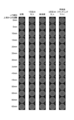
- FIG. 4 and 5 are time-pressure relationship diagrams during the first and second pressurization of pressurized fluid, respectively, and FIG. 6 is an X-ray CT image diagram for each distance from the upper end of the core sample used in the experiment.
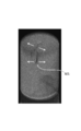
- FIG. 7 is an X-ray CT image showing the fracture mode formed in the core sample.
- the press-fitting pressure rose to the safety upper limit of 9.0 MPa.
- the press-fitting rate once decreased from the initial 5 ⁇ ml / min to nearly 0.5 ⁇ ml / min by the safety control of the apparatus, but gradually turned up and finally recovered to 5 ⁇ ml / min.
- the press-fitting pressure was maintained at 9.0 kg MPa.
- the core was re-restrained by returning the pore pressure to the initial state. In the observation by X-ray CT performed about one day later, the formed crack was closed.
- the second press-fitting was performed about one day after the first press-fitting.
- the pressure suddenly decreased when the press-fitting pressure reached 8.0 kg.
- the injection rate was maintained at 5 ml / min.
- the pressure fluid was adjusted to the range of (2.9 + P0) (MPa) ⁇ P (MPa) ⁇ P1 (MPa) and injected at a predetermined depth of the gas hydrate layer.
- this fracture mode was tensile fracture.
- the excess crushing pressure (difference between crushing pressure and minimum principal stress) in tensile fracture is related to the tensile strength
- the tensile strength of hydrated embryo sand has not been reported so far.
- the tensile strength of methane hydrate alone was determined by experiments (W. Jung, and J. C. Santamarina, Hydrate adhesive and tensile strengths, Geochem. Geophys. Geosyst., 2011, 12, Q08003.) J. Wu, F. Ning, T. T. Trinh, S. Kjelstrup, T. JH Vlugt, J. He, B. H. Skallerud, and Z.
- the tensile strength of hydrate embryo sand depends on crystallinity, crystal grain size, hydrate morphology, hydrate saturation, and effective stress. Conceivable. Theoretically, the overcrushing pressure at the time of tensile failure does not depend on the effective stress, but the results of this experiment fully show that the overcrushing pressure of hydrate embryos may depend on the effective stress. Yes.
- the effective permeability of water before hydraulic crushing was 0.00080 mD (Mildalsea).
- the effective permeability of water after the first hydraulic crushing was 0.014 mD.
- the effective permeability of water after the second hydraulic fracturing was 4.6 mD.
- the second effective water permeability is a value measured after reconstraining the core sample, and the crack was closed at this time. From this, it became clear that even if there was no proppant for retaining cracks, the effective permeability increased by hydraulic fracturing was maintained. In addition, the influence of hydrate fixation and regeneration was not observed on the time axis of this experiment.
- Fig. 8 confirms a decrease in injection pressure in the pressurized fluid at 3.3 MPa or more higher than 5.1 MP, which is the minimum principal stress (circumferential pressure in this experiment), and (2.9 + P0) (MPa) ⁇ P (MPa) A range of pressures is guaranteed in this experiment.
- SYMBOLS 1 Floating type excavator, 2 ... Drill bit, 3 ... Piping, 4 ... Injection pump (supply device), 5 ... Sand protection screen, 6 ... Drain pipe, 7 ... Gas pipe, 10 ... Hydraulic crushing system, G1 ... Upper layer , G2 ... Gas hydrate layer (methane hydrate layer), G3 ... Lower layer, K ... Well, K1, K2 ... Casing, R ... Bare pit, P ... Packer, C ... Crack
Landscapes
- Life Sciences & Earth Sciences (AREA)
- Engineering & Computer Science (AREA)
- Geology (AREA)
- Mining & Mineral Resources (AREA)
- Physics & Mathematics (AREA)
- Environmental & Geological Engineering (AREA)
- Fluid Mechanics (AREA)
- General Life Sciences & Earth Sciences (AREA)
- Geochemistry & Mineralogy (AREA)
- Drilling And Exploitation, And Mining Machines And Methods (AREA)
Abstract
添加物を含まない圧力流体を用いてガスハイドレート層に亀裂を形成するとともに、プロパントを注入することなくガスハイドレート層の良好な浸透性を維持することを可能としたガスハイドレート層における水圧破砕方法と水圧破砕システムを提供すること。ガスハイドレート層G2のうち、亀裂を形成したい所定深度tまで延びて圧力流体の流通する配管3を地盤内に施工し、所定深度における最小応力がP0(MPa)であり、配管3の内部耐圧力がP1(MPa)の場合に、圧力流体の圧力P(MPa)が(2.9+P0)(MPa)≦P(MPa)<P1(MPa)の範囲に調整された該圧力流体をガスハイドレート層G2の所定深度に注入し、該所定深度にて亀裂Cを形成する、ガスハイドレート層における水圧破砕方法である。
Description
本発明は、ガスハイドレート層に圧力流体を供給してガスハイドレート層の一部を破砕するガスハイドレート層における水圧破砕方法と水圧破砕システムに関するものである。
ガスハイドレート層(自然界では主にメタンハイドレートを含む層であるが、ブタンハイドレートなどのその他の天然ガスを含む層を包含する)は、水分子からなる格子内にガス分子が包接された低温高圧条件下で安定な固体結晶である。低温高圧条件を満たす永久凍土下や海底下においてガスハイドレートの存在が確認されており、メタン分子など天然ガス成分を主成分とするガスハイドレートは、石油や石炭に代わる非在来型エネルギー資源として研究・開発が鋭意進められている。
ガスハイドレートを胚胎する地層(ガスハイドレート層)から資源としてガスを生産する手法として、減圧法が提案されている。この減圧法では、坑井をガスハイドレート層まで掘削して導通させ、坑井内に流入した水をポンプでくみ上げることでガスハイドレート層を減圧する。減圧されたガスハイドレートは分解し、発生したガスと水が坑井に向かって流動するため、坑井を通してガスを生産することが可能になる。
この減圧法を適用するには、非特許文献1に記載があるように、ガスと水が流動できるだけの浸透性をガスハイドレート層が有していなくてはならない。仮にガスハイドレート層の浸透性が低い場合は、浸透性を向上させる手法を併用することが求められる。
一方、近年活発化しているシェールガスやシェールオイルの開発では、浸透性の低いシェール層に高圧水等の圧力流体を注入してシェール層を破砕する(水圧破砕)ことにより、浸透性を向上させてシェールガスやシェールオイルの流動を可能にしている。
この水圧破砕では、地層に形成した人工的な亀裂(フラクチャー)が閉塞するのを防止するべく、プロパントとよばれる支持材を圧力流体とともに注入する。このプロパントとしては、砂やセラミックなどの原料が粒状に加工されたものが一般に用いられている。
また、注入する圧力流体には、プロパントを亀裂内に十分に行きわたらせる効果を持たせるため、水にポリマーや油等の添加物を加えることで粘性を上げたものが用いられる。
上記するガスハイドレート層においても、浸透性を向上させる手法としてこの水圧破砕の適用が検討されている。
従来の水圧破砕は、浸透性の低い固結した岩体への適用を想定して開発されたものである。そして、近年は、シルトなどの細粒成分が閉塞してできた坑井周辺の低浸透率部へ流路を作成することを目的に、未固結の堆積層にも適用されるようになってきた。しかし、未固結の堆積層は、従来の水圧破砕が対象としてきた岩体に比べ、一般的に浸透率が大きく、また、粒子間の結合力が弱いという特徴を有している。
ガスハイドレート層は、永久凍土下や海底浅層の未固結堆積層に存在することが知られている。ガスハイドレート層の浸透率や粒子間の結合力は、従来の水圧破砕が対象としてきた岩体とは大きく異なっており、従来の水圧破砕の技術をそのままガスハイドレート層に適用することは困難である。
ここで、特許文献1には、CaCl2、またはCaBr2、またはそれらの混合物の過飽和の温水をガスハイドレート層に注入し、人工的に亀裂を形成させる手法が記載されている。
また、特許文献2には、質量比で10%~75%のアルカリ金属のギ酸塩、または酢酸塩、またはそれらの混合物からなる水溶液を、ガスハイドレート層に注入し、人工的に亀裂を形成させる手法が記載されている。
また、特許文献3には、液化ガスを注入することでガスハイドレート層に亀裂のネットワークを形成させ、その後に熱を与えることでガスハイドレートを分解しガスを回収する手法が記載されている。
また、特許文献4には、ガスハイドレート層に水平方向の亀裂を形成させ、導電性のプロパントを亀裂内に充填して通電することにより、ガスハイドレートからガスを取り出すための熱を生成させる手法が記載されている。
Konno,Y.,Masuda,Y.,Hariguchi,Y.,Kurihara,M.,and Ouchi,H.,Energy Fuels 2010,24,1736-1744
従来の水圧破砕では、ガスハイドレート層内に形成した亀裂を支持(保持)するべく、添加物を加えて粘性調整がおこなわれた圧力流体を用いてプロパントを注入する必要があった。しかしながら、添加物には環境に負荷を与えるものがあること、また、添加物とプロパントを扱うための機器の設置が必要になり、当該機器の設置に手間がかかることや、添加物とプロパントを扱うための工程が増えて工期が長期化する等、従来の水圧破砕には環境面での課題や経済的な課題があった。
上記する各特許文献のうち、特許文献1及び特許文献2に記載の技術では注入する流体に添加物を加えており、また、特許文献3では注入する流体に液化ガスを用いていることから、上記の課題を内包している。
また、特許文献4に記載の技術ではプロパントを用いており、特許文献1~3と同様に上記の課題を内包している。
このように、ガスハイドレート層内に形成した亀裂を支持(保持)するためにはプロパントを用いる必要があると従来は考えられており、プロパントを用いないでガスハイドレート層に形成した亀裂を保持する発想は一切ない。
本発明は上記する問題に鑑みてなされたものであり、添加物を含まない圧力流体を用いてガスハイドレート層に亀裂を形成するとともに、プロパントを注入することなくガスハイドレート層の良好な浸透性を維持することを可能とし、もって、環境面での課題や経済的な課題を回避しながらガスハイドレート層を水圧破砕することのできる、ガスハイドレート層における水圧破砕方法と水圧破砕システムを提供することを目的としている。
前記目的を達成すべく、本発明によるガスハイドレート層における水圧破砕方法は、ガスハイドレート層のうち、亀裂を形成したい所定深度まで延びて圧力流体の流通する配管を地盤内に施工し、前記所定深度における最小応力がP0(MPa)であり、前記配管の内部耐圧力がP1(MPa)の場合に、前記圧力流体の圧力P(MPa)が(2.9+P0)(MPa)≦P(MPa)<P1(MPa)の範囲に調整された該圧力流体を前記ガスハイドレート層の前記所定深度に注入し、該所定深度にて亀裂を形成するものである。
本発明の水圧破砕方法は、ガスハイドレート層のうち、亀裂を形成したい所定深度における最小応力がP0(MPa)、配管の内部耐圧力がP1(MPa)の場合に、圧力P(MPa)が(2.9+P0)(MPa)≦P(MPa)<P1(MPa)の範囲に調整された圧力流体を注入することにより、形成された亀裂を保持するためのプロパントも該プロパントを行きわたらせるための添加物も含まない圧力流体を用いた場合でも、亀裂を十分に保持することができ、ガスハイドレート層内の有効浸透率を格段に向上させることを可能とした方法である。
上記する圧力流体の圧力範囲のうち、下限値の(2.9+P0)(MPa)は本発明者等による検証実験によって特定されたものである。
このように、上記数値範囲の圧力を有する圧力流体をガスハイドレート層に適用することで形成された亀裂を良好に保持できる理由は、メタンハイドレート等のガスハイドレート特有の地盤性状との関連性である。具体的には、シェールオイル層などでは層が固結していることから、この固結した層に亀裂を形成した場合、亀裂が閉塞するのを防止するべくプロパント等の提供が必要となる。一方、メタンハイドレート層は、粒径が100~200μmの範囲のものを中心とした大きさの未固結の堆積物粒子から形成されており、濡れた砂を凍らせたような地層をなしている。メタンハイドレート層に亀裂を入れると、メタンハイドレートを介して互いに固着していた砂がはがれるため、亀裂面が部分的に崩れ、さらに減圧することで、亀裂周辺のメタンハイドレートが優先的に分解(凍っていた部分が融解)し、亀裂面がさらに崩れる。崩れた部分から生じた砂が、プロパントの代わりの役割を果たし、形成された亀裂を保持すると考えられるためである。なお、シェールオイル層は固結しているため、亀裂が入ったとしても層がずれる程度で、メタンハイドレート層のように亀裂から粒子が発生することはない。
このように、ガスハイドレート層に亀裂を生じさせる最適な圧力流体の圧力範囲が(2.9+P0)(MPa)≦P(MPa)<P1(MPa)の範囲であり、この圧力流体の注入にてガスハイドレート層に形成された亀裂の保持をガスハイドレート層の亀裂面から生じた砂が保証するものである。
ここで、適用する圧力流体は、プロパントを亀裂内に行きわたらせるための添加物を含んでいない、水、海水、淡水あるいは蒸留水のいずれか一種を挙げることができる。さらに、このような添加物等を含んでいないことから、圧力流体はプロパントを含む必要もない。この「添加物」とは、既述するように、ポリマーや油等を意味する。
ここで、「亀裂を形成したい所定深度」とは、ある層厚のガスハイドレート層において、特定の深度の場合はその深度が所定深度となり、所定深度が一定の高さ範囲を対象とする場合はその上下限の深度が所定深度となる。後者の場合、圧力流体を注入する箇所は、一定の高さ範囲の上限位置から下限位置まで複数箇所に及ぶ場合もあれば、一定の高さ範囲の中間位置を注入箇所に設定する場合もある。
また、本発明はガスハイドレート層における水圧破砕システムにも及ぶものであり、この水圧破砕システムは、ガスハイドレート層に圧力流体を供給してガスハイドレート層の一部を破砕するガスハイドレート層における水圧破砕システムであって、ガスハイドレート層のうち、亀裂を形成したい所定深度まで延びて圧力流体の流通する配管と、前記圧力流体を前記所定深度に供給する供給装置と、を備え、前記所定深度における最小応力がP0(MPa)であり、前記配管の内部耐圧力がP1(MPa)の場合に、前記供給装置において、前記圧力流体の圧力P(MPa)が(2.9+P0)(MPa)≦P(MPa)<P1(MPa)の範囲に調整されるものである。
ここで、圧力流体の流通する配管としては、その全部もしくは一部の側方に圧力流体が吐出する吐出孔を有しており、下端が閉塞している形態が挙げられる。また、供給装置としてはポンプ等が挙げられる。適用される供給装置による圧力流体の注入圧力P(MPa)が(2.9+P0)(MPa)≦P(MPa)<P1(MPa)の範囲に調整されて本システムが適用される。
たとえば、海上に浮遊式掘削装置を停泊させ、海底面からガスハイドレート層まで坑井を造成し、造成された坑井に掘削船からガスハイドレート層まで延びる鋼管等の配管を配設する。
掘削船にポンプ等の供給装置が搭載されており、上記する注入圧力P(MPa)に調整された圧力流体を、配管を介してガスハイドレート層において亀裂を形成したい所定深度に注入することができる。
本発明の水圧破砕システムを適用することで、添加物を含まない圧力流体を使ってガスハイドレート層に亀裂を形成するとともに、プロパントを注入することなく、ガスハイドレート層の良好な浸透性を維持することが可能になる。
以上の説明から理解できるように、本発明のガスハイドレート層における水圧破砕方法と水圧破砕システムによれば、ガスハイドレート層のうち、亀裂を形成したい所定深度における最小応力がP0(MPa)、配管の内部耐圧力がP1(MPa)の場合に、圧力P(MPa)が(2.9+P0)(MPa)≦P(MPa)<P1(MPa)の範囲に調整された圧力流体を注入することにより、亀裂を保持するプロパントも該プロパントを行きわたらせる添加物も含まない圧力流体を適用した場合でも、ガスハイドレート層に亀裂を効果的に形成できるとともに、形成された亀裂を十分に保持することができ、ガスハイドレート層における良好な浸透性を保証することができる。したがって、プロパントや添加物を用いた場合に生じ得る、環境に負荷を与えるといった課題や、添加物とプロパントを扱うための工程が増えて工期が長期化する等の経済的な課題を解消しながら、ガスを効果的に回収することができる。
以下、図面を参照して本発明のガスハイドレート層における水圧破砕方法と水圧破砕システムの実施の形態を説明する。なお、海底地盤の層構成については図示例以外にも多様に存在し、ガスハイドレート層が傾斜したり湾曲している層形状の場合もあり得る。また、掘削装置は図示例の装置に限定されるものではなく、着底型リグ、甲板昇降型リグ、船型リグなど、多様な掘削装置が適用可能である。
(ガスハイドレート層における水圧破砕方法と水圧破砕システムの実施の形態)
図1は本発明の水圧破砕方法を説明したフロー図であり、図2は図1に続いて水圧破砕方法を説明したフロー図であって、本発明の水圧破砕システムをともに示した図であり、図3は図2に続いて水圧破砕方法を説明したフロー図である。
図1は本発明の水圧破砕方法を説明したフロー図であり、図2は図1に続いて水圧破砕方法を説明したフロー図であって、本発明の水圧破砕システムをともに示した図であり、図3は図2に続いて水圧破砕方法を説明したフロー図である。
図1で示すように、海底には、上層G1,ガスハイドレート層G2,下層G3が成層をなしている。本発明の水圧破砕方法をガスハイドレート層G2の所定深度に適用して人工的な亀裂(フラクチャー)を形成し、ガスハイドレート層G2の浸透性を向上させてガスハイドレートから発生したガスの流動を促進させる。
まず、海上に半潜水型の浮遊式掘削装置1を停泊させ、浮遊式掘削装置1からドリルビット2を海底地盤内に降下させ、ドリルビット2で地盤を所定深度まで掘削した段階で坑壁防護用のケーシングK1を設置し、ケーシングK1とその背面の地盤の間にセメントを注入してケーシングK1の固定を図る。
次に、上層G1のケーシングK1以深においては、ケーシングK1よりも小径のケーシングK2をケーシングK1の内側に設置し、ケーシングK2とその背面の地盤の間にセメントを注入してケーシングK2の固定を図る。
ガスハイドレート層G2において、水圧破砕方法を適用して人工的な亀裂を形成したい所定深度tまでドリルビット2で地盤を掘削し、ガスハイドレート層G2内においてはケーシングを設置することなく、裸坑Rを造成し、ケーシングK1、K2および裸坑Rからなる坑井Kが施工される。
次に、図2で示すように、浮遊式掘削装置1から坑井K(裸坑R)の下端まで延び、少なくとも裸坑R内にある箇所の側方に多数の吐出孔が開設され、下端が閉塞した鋼管からなる配管3を配設し、配管3と裸坑Rのアニュラス部の上下二箇所において硬質ゴム製のバルーンからなるパッカーPを設置して、配管3の裸坑R内固定を図るとともに上下二箇所のパッカーPにてその間の空間を圧力的に隔離する。
浮遊式掘削装置1には配管3を介して圧力流体をガスハイドレート層G2に提供するための供給装置である注入ポンプ4が搭載されており、これら配管3と注入ポンプ4から水圧破砕システム10が構成される。
ここで、ガスハイドレート層G2の所定深度tにおける最小応力がP0(MPa)であり、配管3の内部耐圧力がP1(MPa)の場合に、注入される圧力流体の圧力P(MPa)を(2.9+P0)(MPa)≦P(MPa)<P1(MPa)の範囲に調整し、この範囲に圧力調整された圧力流体を配管3を介してガスハイドレート層G2に注入して(X1方向)亀裂Cを形成する。
注入する圧力流体は、水、海水、淡水あるいは蒸留水のいずれか一種からなり、ポリマーや油等からなる添加物もプロパントも含んでいない。
上記する圧力範囲内の圧力流体をガスハイドレート層G2の所定深度tに注入することにより、亀裂Cを保持するプロパントもこのプロパントを行きわたらせる添加物も含まない圧力流体を適用した場合でも、ガスハイドレート層G2に亀裂Cを効果的に形成できるとともに、形成された亀裂Cを十分に保持することができ、ガスハイドレート層G2における良好な浸透性を保証することができる。
メタンハイドレート層等のガスハイドレート層G2は、未固結の堆積物粒子から層が形成されており、濡れた砂を凍らせたような地層をなしている。メタンハイドレート層G2に亀裂Cを入れると、メタンハイドレートを介して互いに固着していた砂がはがれるため、亀裂面が部分的に崩れ、さらに減圧することで、亀裂周辺のメタンハイドレートが優先的に分解し、亀裂面がさらに崩れ、崩れた部分から生じた砂が発生する。そのため、メタンハイドレート層G2では、この発生した砂がプロパントの代わりの役割を果たし、形成された亀裂Cを発生した砂が保持すると考えられることから、亀裂Cを保持するプロパントもこのプロパントを行きわたらせる添加物も不要となる。
所定量の圧力流体をガスハイドレート層G2に注入した後、配管3に繋がる不図示のバルブを閉制御して配管3を閉塞することにより、配管3の閉塞をおこない、ガスハイドレート層G2内の圧力挙動を不図示の圧力センサにて計測し、計測結果を随時観測しながら、ガスハイドレート層G2を構成する未固結の堆積物粒子によって亀裂Cが支持されるのを待つ。
ガスハイドレート層G2内の圧力が低下して一定値に収斂したことをもって、ガスハイドレート層G2を構成する未固結の堆積物粒子によって亀裂Cが支持されたことと同定できる。
未固結の堆積物粒子によって亀裂Cが支持されたことが確認できたら、水圧破砕用の配管3を坑井Kから撤去し、図3に示すように、裸坑R内に金属製もしくは多孔質性の砂防護スクリーン5を設置する。さらに、排水管6をその下端が裸坑Rの下方位置まで延びた状態で設置するとともに、ガス管7をその下端が裸坑Rの上方位置まで延びた状態で設置する。
排水管6内のバルブを閉じた状態から開放することにより、図3で示すように、砂防護スクリーン5を介して坑井K内にはガスハイドレート層G2内から地下水Wが流入する(X2方向)。この地下水Wの流入において、崩れた砂は砂防護スクリーン5によって裸坑R内に浸入するのが防止される。
排水管6内には不図示の汲み上げポンプが内蔵されており、この汲み上げポンプを作動させて坑井K内の地下水Wを排水管6内に吸い込み、地下水Wを海上に汲み上げる(X3方向)。
地下水Wの汲み上げにより、ガスハイドレート層G2が減圧される。ガスハイドレート層G2が減圧されることでガスハイドレートが分解し、発生したガスと地下水Wが裸坑Rに向かって流動する。砂防護スクリーン5を介して裸坑R内に流入してきたガスをガス管7を介して地上に送ることにより(X4方向)、ガスの生産が実行される。
なお、図示例は、圧力流体を注入する配管3と地下水汲み上げ用の排水管6を別途の配管にておこなう形態であるが、同一の配管にて圧力流体の注入と地下水の汲み上げをおこなう形態であってもよい。
図示するガスハイドレート層G2における水圧破砕方法と水圧破砕システム10によれば、亀裂Cを保持するプロパントもこのプロパントを行きわたらせる添加物も含まない圧力流体を適用した場合でも、ガスハイドレート層G2に亀裂Cを効果的に形成できるとともに、形成された亀裂Cを十分に保持することができ、ガスハイドレート層G2における良好な浸透性を保証することができる。そのため、プロパントや添加物を用いた場合に生じ得る、環境に負荷を与えるといった課題や、添加物とプロパントを扱うための工程が増えて工期が長期化する等の経済的な課題を解消しながら、ガスを効果的に回収することができる。
(水圧破砕を模擬した室内実験その1とその結果)
本発明者等は、水圧破砕を模擬した室内実験その1をおこない、ガスハイドレート層に効果的に亀裂を形成するための圧力流体の最適な圧力範囲を特定することとした。
本発明者等は、水圧破砕を模擬した室内実験その1をおこない、ガスハイドレート層に効果的に亀裂を形成するための圧力流体の最適な圧力範囲を特定することとした。
本実験では、アルミ合金で形成され、軸圧と周圧をそれぞれ独立に制御できる3軸応力付加型の圧力セルを用いて室内実験をおこなった。また、コア試料における亀裂の形成状況はX線CT装置にて撮像し、観察した。
実験手順は以下の通りである。すなわち、含水させた豊浦砂をゴムスリーブ内に詰め、直径50 mm、長さ69.9 mmの円筒状のコアを作成した。圧力セルの軸圧を2.1 MPa、周圧を1.1 MPaに制御し、有効応力を維持しながらメタンガスを4.1 MPaまで加圧した。そして、温度をおよそ276 Kに低下させることでメタンハイドレートを生成した。メタンハイドレート生成後、蒸留水で残留ガスを排除することにより、メタンハイドレート飽和率が72%、水飽和率が28%のメタンハイドレート胚胎砂を作成した。ここで、孔隙圧、軸圧、周圧をそれぞれ、4.1 MPa、6.1 MPa、5.1 MPaに設定し、温度をおよそ276 Kに制御した。水圧破砕のため、コア試料上端の3 mm径の圧入孔から蒸留水を5 ml/分で計10 mlに至るまで圧入し、この間、軸圧・周圧は一定に保持した。水圧破砕の前・後、および再拘束によって亀裂が閉じた後の各ステップでX線CTによる観察をおこなうとともに、水の有効浸透率を計測した。
(実験結果)
本実験では、圧入を2回実施した。図4,5はそれぞれ、1回目と2回目の圧力流体の圧入の際の時間-圧力関係図であり、図6は実験で用いたコア試料の上端からの距離ごとのX線CT画像図であり、図7はコア試料に形成された破壊モードを示したX線CT画像図である。
本実験では、圧入を2回実施した。図4,5はそれぞれ、1回目と2回目の圧力流体の圧入の際の時間-圧力関係図であり、図6は実験で用いたコア試料の上端からの距離ごとのX線CT画像図であり、図7はコア試料に形成された破壊モードを示したX線CT画像図である。
1回目の圧入では、圧入圧が装置の安全上限9.0 MPaまで上昇した。その結果、装置の安全制御によって、圧入レートは初期の5 ml/分から0.5 ml/分近くまで一度低下したが、徐々に上昇に転じ、最終的には5 ml/分に回復した。この間、圧入圧は9.0 MPaに維持された。
X線CTによる観察の結果、コア試料の上端から0~20 mmの範囲に、圧入孔を起点とする小さい亀裂が確認された。
孔隙圧を初期状態に戻すことでコアを再拘束した。およそ1日後に実施したX線CTによる観察では、形成された亀裂は閉じていた。
2回目の圧入は1回目の圧入からおよそ1日後に実施した。2回目の圧入では、圧入圧が8.0 MPaに達したところで急激に低下に転じた。この間、圧入レートは5 ml/分に維持された。
X線CTによる観察の結果、1回目の圧入で形成された亀裂(コア試料の上端から0~20 mm)が再度開いて広がり、コア試料の下端(コア上端から25~60 mm)に向けて拡大したことが明らかになった。
いくつかのつながった亀裂が、最小主応力に直交する方向のコア試料の長手方向に向けて発達した。亀裂はまっすぐでかつ薄層状であり、屈曲が少なく、コア試料の半径方向に形成された。
以上の結果より、メタンハイドレート胚胎砂では、8.0~9.0 MPaで亀裂が形成され、その圧力は最小主応力(この実験では周圧)である5.1 MPより2.9~3.9 MPa高い圧力であることが明らかになった。
本実験結果に基づき、ガスハイドレート層において亀裂を形成したい所定深度における最小応力がP0(MPa)の際に、圧力流体の圧力P(MPa)を(2.9+P0)(MPa)≦P(MPa)の条件となるように圧力制御し、圧力流体の注入を実行することとした。
また、圧力流体の圧力が当該圧力流体が流通する有孔配管の内部耐圧力未満であることも必須であることに鑑み、有孔配管の内部耐圧力がP1(MPa)の場合に、圧力流体の圧力P(MPa)を(2.9+P0)(MPa)≦P(MPa)<P1(MPa)の範囲に調整してガスハイドレート層の所定深度に注入することとした。
また、本実験にて観察されたコア試料に形成された破壊モードを図7に示す。
図7で示すように、本破壊モードは引張り破壊であった。引張り破壊における超過破砕圧(破砕圧と最小主応力の差)は、引張強度に相関があると言われているものの、ハイドレート胚胎砂の引張強度はこれまで報告されていない。一方、メタンハイドレート単体の引張強度は、実験(W. Jung, and J. C. Santamarina, Hydrate adhesive and tensile strengths, Geochem. Geophys. Geosyst., 2011, 12, Q08003.)や分子動力学計算(J. Wu, F. Ning, T. T. Trinh, S. Kjelstrup, T. J.H. Vlugt, J. He, B. H. Skallerud, and Z. Zhang, Mechanical instability of monocrystalline and polycrystalline methane hydrates, Nature Communications, 2015, 6, Article number: 8743.)による研究結果が報告されており、この中で、ハイドレートの引張強度は、その結晶度や結晶粒径に依存することが示唆されており、結晶度や結晶粒径が様々な実験ではサブMPaオーダー、それらが均一な分子動力学計算ではサブGPaオーダーの値が報告されている。砂層中のメタンハイドレートの結晶度や結晶粒径は様々であると考えられることから、本実験で得られた超過破砕圧2.9~3.9 MPaは、既往の実験で報告されているメタンハイドレート単体の引張強度(サブMPaオーダー)と整合するはずだが、実際はそれよりも一桁高い値であった。
既往の実験と本実験の違いは有効応力の有無であることから、ハイドレート胚胎砂の引張強度は、結晶度、結晶粒径、ハイドレートのモホロジー、ハイドレート飽和率、および有効応力に依存すると考えられる。理論的には、引張り破壊が生じた際の超過破砕圧は有効応力に依存しないが、本実験の結果は、ハイドレート胚胎砂の超過破砕圧が有効応力に依存する可能性を十分に示している。
次に、水圧破砕の前後、および再拘束によって亀裂が閉じた後の水の有効浸透率を圧力緩和試験および流動試験を通して計測した。
まず、水圧破砕の前(初期)の水の有効浸透率は、0.00080 mD(ミリダルシー)であった。次に、1回目の水圧破砕後の水の有効浸透率は、0.014 mDであった。次に、2回目の水圧破砕後の水の有効浸透率は、4.6 mDであった。
2回目の水の有効浸透率はコア試料を再拘束した後に計測した値であり、この際に亀裂は閉じていた。このことから、亀裂を保持するためのプロパントがなくても、水圧破砕によって上昇した有効浸透率が維持されることが明らかになった。また、ハイドレートの固着や再生成による影響も本実験の時間軸では認められなかった。
(水圧破砕を模擬した室内実験その2とその結果)
本発明者等は、水圧破砕を模擬した室内実験その2をおこなった。この室内実験の実験方法とその詳細は室内実験その1とほぼ同様である。その結果を図8に示す。
本発明者等は、水圧破砕を模擬した室内実験その2をおこなった。この室内実験の実験方法とその詳細は室内実験その1とほぼ同様である。その結果を図8に示す。
図8より、最小主応力(この実験では周圧)である5.1 MPより3.3 MPa以上高い圧力の圧力流体にて注入圧力の低下が確認され、(2.9+P0)(MPa)≦P(MPa)の範囲の圧力範囲が本実験でも保証されている。
以上、本発明の実施の形態を図面を用いて詳述してきたが、具体的な構成はこの実施形態に限定されるものではなく、本発明の要旨を逸脱しない範囲における設計変更等があっても、それらは本発明に含まれるものである。
1…浮遊式掘削装置、2…ドリルビット、3…配管、4…注入ポンプ(供給装置)、5…砂防護スクリーン、6…排水管、7…ガス管、10…水圧破砕システム、G1…上層、G2…ガスハイドレート層(メタンハイドレート層)、G3…下層、K…坑井、K1,K2…ケーシング、R…裸坑、P…パッカー、C…亀裂
Claims (4)
- ガスハイドレート層のうち、亀裂を形成したい所定深度まで延びて圧力流体の流通する配管を地盤内に施工し、
前記所定深度における最小応力がP0(MPa)であり、前記配管の内部耐圧力がP1(MPa)の場合に、前記圧力流体の圧力P(MPa)が(2.9+P0)(MPa)≦P(MPa)<P1(MPa)の範囲に調整された該圧力流体を前記ガスハイドレート層の前記所定深度に注入し、該所定深度にて亀裂を形成する、ガスハイドレート層における水圧破砕方法。 - 前記圧力流体が、添加物とプロパントを含んでいない、水、海水、淡水あるいは蒸留水のいずれか一種からなる、請求項1に記載のガスハイドレート層における水圧破砕方法。
- ガスハイドレート層に圧力流体を供給してガスハイドレート層の一部を破砕するガスハイドレート層における水圧破砕システムであって、
ガスハイドレート層のうち、亀裂を形成したい所定深度まで延びて圧力流体の流通する配管と、
前記圧力流体を前記所定深度に供給する供給装置と、を備え、
前記所定深度における最小応力がP0(MPa)であり、前記配管の内部耐圧力がP1(MPa)の場合に、前記供給装置において、前記圧力流体の圧力P(MPa)が(2.9+P0)(MPa)≦P(MPa)<P1(MPa)の範囲に調整される、ガスハイドレート層における水圧破砕システム。 - 前記圧力流体が、添加物とプロパントを含んでいない、水、海水、淡水あるいは蒸留水のいずれか一種からなる、請求項3に記載のガスハイドレート層における水圧破砕システム。
Priority Applications (1)
| Application Number | Priority Date | Filing Date | Title |
|---|---|---|---|
| JP2018526333A JP6635528B2 (ja) | 2016-07-04 | 2017-06-30 | ガスハイドレート層における水圧破砕方法と水圧破砕システム |
Applications Claiming Priority (2)
| Application Number | Priority Date | Filing Date | Title |
|---|---|---|---|
| JP2016132815 | 2016-07-04 | ||
| JP2016-132815 | 2016-07-04 |
Publications (1)
| Publication Number | Publication Date |
|---|---|
| WO2018008535A1 true WO2018008535A1 (ja) | 2018-01-11 |
Family
ID=60912167
Family Applications (1)
| Application Number | Title | Priority Date | Filing Date |
|---|---|---|---|
| PCT/JP2017/024072 Ceased WO2018008535A1 (ja) | 2016-07-04 | 2017-06-30 | ガスハイドレート層における水圧破砕方法と水圧破砕システム |
Country Status (2)
| Country | Link |
|---|---|
| JP (1) | JP6635528B2 (ja) |
| WO (1) | WO2018008535A1 (ja) |
Cited By (2)
| Publication number | Priority date | Publication date | Assignee | Title |
|---|---|---|---|---|
| CN113984807A (zh) * | 2021-10-28 | 2022-01-28 | 中国科学院西北生态环境资源研究院 | 基于冻融和压裂作用下岩石裂隙实时扩展的试验方法 |
| US11499407B2 (en) * | 2020-02-28 | 2022-11-15 | Institute Of Geology And Geophysics, Chinese Academy Of Sciences | Exploiting structure for natural gas hydrate reservoir and exploiting method for natural gas hydrate by injecting hydraulic calcium oxide via gas fracturing |
Citations (1)
| Publication number | Priority date | Publication date | Assignee | Title |
|---|---|---|---|---|
| JP2016108867A (ja) * | 2014-12-09 | 2016-06-20 | 三井造船株式会社 | ガスハイドレート回収方法およびその回収システム |
Family Cites Families (2)
| Publication number | Priority date | Publication date | Assignee | Title |
|---|---|---|---|---|
| DE19906147A1 (de) * | 1999-02-13 | 2000-08-17 | Heinz Hoelter | Verfahren zur Gewinnung von gefrorenem Gas auf dem Meeresgrund |
| JP5316878B2 (ja) * | 2009-10-14 | 2013-10-16 | 清水建設株式会社 | メタンハイドレートからのメタンガス生産装置及びこれを用いたメタンハイドレートからのメタンガス生産方法 |
-
2017
- 2017-06-30 WO PCT/JP2017/024072 patent/WO2018008535A1/ja not_active Ceased
- 2017-06-30 JP JP2018526333A patent/JP6635528B2/ja active Active
Patent Citations (1)
| Publication number | Priority date | Publication date | Assignee | Title |
|---|---|---|---|---|
| JP2016108867A (ja) * | 2014-12-09 | 2016-06-20 | 三井造船株式会社 | ガスハイドレート回収方法およびその回収システム |
Cited By (2)
| Publication number | Priority date | Publication date | Assignee | Title |
|---|---|---|---|---|
| US11499407B2 (en) * | 2020-02-28 | 2022-11-15 | Institute Of Geology And Geophysics, Chinese Academy Of Sciences | Exploiting structure for natural gas hydrate reservoir and exploiting method for natural gas hydrate by injecting hydraulic calcium oxide via gas fracturing |
| CN113984807A (zh) * | 2021-10-28 | 2022-01-28 | 中国科学院西北生态环境资源研究院 | 基于冻融和压裂作用下岩石裂隙实时扩展的试验方法 |
Also Published As
| Publication number | Publication date |
|---|---|
| JPWO2018008535A1 (ja) | 2019-04-04 |
| JP6635528B2 (ja) | 2020-01-29 |
Similar Documents
| Publication | Publication Date | Title |
|---|---|---|
| Lu et al. | A new method of drilling long boreholes in low permeability coal by improving its permeability | |
| RU2460876C1 (ru) | Способ осуществления импульсного гидроразрыва карбонатного пласта | |
| US10655443B2 (en) | Pulsed hydraulic fracturing with geopolymer precursor fluids | |
| RU2544343C1 (ru) | Способ гидроразрыва низкопроницаемого пласта с глинистыми прослоями и подошвенной водой | |
| FR3025244A1 (fr) | Operations de formation souterraine utilisant des dispositifs degradables d'isolation des puits de forage. | |
| NO803618L (no) | Fremgangsmaate ved sementering av broennvegger. | |
| JP7299643B2 (ja) | 海域天然ガスハイドレートの筒式採掘装置およびその方法 | |
| US11697760B2 (en) | System and method for utilizing oolitic aragonite as a proppant in hydraulic fracking | |
| US9366125B2 (en) | Carbonate based slurry fracturing using solid acid for unconventional reservoirs | |
| US7909099B2 (en) | Well productivity enhancement methods | |
| US11015417B2 (en) | Using cement slurries in hydrajetting tools | |
| CA2993274A1 (en) | Use of crosslinked polymer system for mitigation of annular pressure buildup | |
| NO346341B1 (no) | Metode for behandling av underjordisk formasjon | |
| JP2023500002A (ja) | 海域天然ガスハイドレートの侵入式採掘装置および採掘方法 | |
| CN104963660A (zh) | 一种液氮冻融裂化煤层增透的煤层气开采方法 | |
| CN107587529B (zh) | 气水压力平衡式地下防渗止水工艺及所用的设备 | |
| JP6635528B2 (ja) | ガスハイドレート層における水圧破砕方法と水圧破砕システム | |
| RU2485306C1 (ru) | Способ гидравлического разрыва пласта в скважине | |
| CN111173480B (zh) | 一种天然气水合物开采方法 | |
| US20240124764A1 (en) | Gas Generating Compositions And Uses | |
| CN106223923A (zh) | 煤层压裂方法 | |
| RU2592582C1 (ru) | Способ гидравлического разрыва пласта | |
| CN110785538A (zh) | 利用含碳浆料的等离子体脉冲水力压裂 | |
| Shilova et al. | Sealing quality increasing of coal seam gas drainage wells by barrier screening method | |
| RU2541693C1 (ru) | Способ гидравлического разрыва пласта в открытом горизонтальном стволе скважины |
Legal Events
| Date | Code | Title | Description |
|---|---|---|---|
| ENP | Entry into the national phase |
Ref document number: 2018526333 Country of ref document: JP Kind code of ref document: A |
|
| 121 | Ep: the epo has been informed by wipo that ep was designated in this application |
Ref document number: 17824140 Country of ref document: EP Kind code of ref document: A1 |
|
| NENP | Non-entry into the national phase |
Ref country code: DE |
|
| 122 | Ep: pct application non-entry in european phase |
Ref document number: 17824140 Country of ref document: EP Kind code of ref document: A1 |