WO2018008218A1 - Information processing device, information processing method, and program - Google Patents
Information processing device, information processing method, and program Download PDFInfo
- Publication number
- WO2018008218A1 WO2018008218A1 PCT/JP2017/014459 JP2017014459W WO2018008218A1 WO 2018008218 A1 WO2018008218 A1 WO 2018008218A1 JP 2017014459 W JP2017014459 W JP 2017014459W WO 2018008218 A1 WO2018008218 A1 WO 2018008218A1
- Authority
- WO
- WIPO (PCT)
- Prior art keywords
- operation object
- user
- information processing
- display
- information
- Prior art date
Links
Images


Classifications
-
- G—PHYSICS
- G06—COMPUTING; CALCULATING OR COUNTING
- G06F—ELECTRIC DIGITAL DATA PROCESSING
- G06F3/00—Input arrangements for transferring data to be processed into a form capable of being handled by the computer; Output arrangements for transferring data from processing unit to output unit, e.g. interface arrangements
- G06F3/01—Input arrangements or combined input and output arrangements for interaction between user and computer
- G06F3/048—Interaction techniques based on graphical user interfaces [GUI]
- G06F3/0484—Interaction techniques based on graphical user interfaces [GUI] for the control of specific functions or operations, e.g. selecting or manipulating an object, an image or a displayed text element, setting a parameter value or selecting a range
-
- G—PHYSICS
- G06—COMPUTING; CALCULATING OR COUNTING
- G06F—ELECTRIC DIGITAL DATA PROCESSING
- G06F3/00—Input arrangements for transferring data to be processed into a form capable of being handled by the computer; Output arrangements for transferring data from processing unit to output unit, e.g. interface arrangements
- G06F3/01—Input arrangements or combined input and output arrangements for interaction between user and computer
- G06F3/017—Gesture based interaction, e.g. based on a set of recognized hand gestures
-
- G—PHYSICS
- G06—COMPUTING; CALCULATING OR COUNTING
- G06F—ELECTRIC DIGITAL DATA PROCESSING
- G06F1/00—Details not covered by groups G06F3/00 - G06F13/00 and G06F21/00
- G06F1/16—Constructional details or arrangements
- G06F1/1613—Constructional details or arrangements for portable computers
- G06F1/163—Wearable computers, e.g. on a belt
-
- G—PHYSICS
- G06—COMPUTING; CALCULATING OR COUNTING
- G06F—ELECTRIC DIGITAL DATA PROCESSING
- G06F3/00—Input arrangements for transferring data to be processed into a form capable of being handled by the computer; Output arrangements for transferring data from processing unit to output unit, e.g. interface arrangements
- G06F3/01—Input arrangements or combined input and output arrangements for interaction between user and computer
- G06F3/011—Arrangements for interaction with the human body, e.g. for user immersion in virtual reality
- G06F3/013—Eye tracking input arrangements
-
- G—PHYSICS
- G06—COMPUTING; CALCULATING OR COUNTING
- G06F—ELECTRIC DIGITAL DATA PROCESSING
- G06F3/00—Input arrangements for transferring data to be processed into a form capable of being handled by the computer; Output arrangements for transferring data from processing unit to output unit, e.g. interface arrangements
- G06F3/01—Input arrangements or combined input and output arrangements for interaction between user and computer
- G06F3/048—Interaction techniques based on graphical user interfaces [GUI]
- G06F3/0481—Interaction techniques based on graphical user interfaces [GUI] based on specific properties of the displayed interaction object or a metaphor-based environment, e.g. interaction with desktop elements like windows or icons, or assisted by a cursor's changing behaviour or appearance
- G06F3/04812—Interaction techniques based on cursor appearance or behaviour, e.g. being affected by the presence of displayed objects
-
- G—PHYSICS
- G06—COMPUTING; CALCULATING OR COUNTING
- G06F—ELECTRIC DIGITAL DATA PROCESSING
- G06F3/00—Input arrangements for transferring data to be processed into a form capable of being handled by the computer; Output arrangements for transferring data from processing unit to output unit, e.g. interface arrangements
- G06F3/01—Input arrangements or combined input and output arrangements for interaction between user and computer
- G06F3/048—Interaction techniques based on graphical user interfaces [GUI]
- G06F3/0481—Interaction techniques based on graphical user interfaces [GUI] based on specific properties of the displayed interaction object or a metaphor-based environment, e.g. interaction with desktop elements like windows or icons, or assisted by a cursor's changing behaviour or appearance
- G06F3/04815—Interaction with a metaphor-based environment or interaction object displayed as three-dimensional, e.g. changing the user viewpoint with respect to the environment or object
-
- G—PHYSICS
- G06—COMPUTING; CALCULATING OR COUNTING
- G06F—ELECTRIC DIGITAL DATA PROCESSING
- G06F3/00—Input arrangements for transferring data to be processed into a form capable of being handled by the computer; Output arrangements for transferring data from processing unit to output unit, e.g. interface arrangements
- G06F3/01—Input arrangements or combined input and output arrangements for interaction between user and computer
- G06F3/048—Interaction techniques based on graphical user interfaces [GUI]
- G06F3/0481—Interaction techniques based on graphical user interfaces [GUI] based on specific properties of the displayed interaction object or a metaphor-based environment, e.g. interaction with desktop elements like windows or icons, or assisted by a cursor's changing behaviour or appearance
- G06F3/0482—Interaction with lists of selectable items, e.g. menus
-
- G—PHYSICS
- G06—COMPUTING; CALCULATING OR COUNTING
- G06F—ELECTRIC DIGITAL DATA PROCESSING
- G06F3/00—Input arrangements for transferring data to be processed into a form capable of being handled by the computer; Output arrangements for transferring data from processing unit to output unit, e.g. interface arrangements
- G06F3/16—Sound input; Sound output
- G06F3/167—Audio in a user interface, e.g. using voice commands for navigating, audio feedback
-
- G—PHYSICS
- G06—COMPUTING; CALCULATING OR COUNTING
- G06V—IMAGE OR VIDEO RECOGNITION OR UNDERSTANDING
- G06V20/00—Scenes; Scene-specific elements
- G06V20/60—Type of objects
- G06V20/64—Three-dimensional objects
-
- G—PHYSICS
- G06—COMPUTING; CALCULATING OR COUNTING
- G06V—IMAGE OR VIDEO RECOGNITION OR UNDERSTANDING
- G06V40/00—Recognition of biometric, human-related or animal-related patterns in image or video data
- G06V40/20—Movements or behaviour, e.g. gesture recognition
-
- G—PHYSICS
- G08—SIGNALLING
- G08C—TRANSMISSION SYSTEMS FOR MEASURED VALUES, CONTROL OR SIMILAR SIGNALS
- G08C17/00—Arrangements for transmitting signals characterised by the use of a wireless electrical link
-
- H—ELECTRICITY
- H04—ELECTRIC COMMUNICATION TECHNIQUE
- H04N—PICTORIAL COMMUNICATION, e.g. TELEVISION
- H04N21/00—Selective content distribution, e.g. interactive television or video on demand [VOD]
- H04N21/40—Client devices specifically adapted for the reception of or interaction with content, e.g. set-top-box [STB]; Operations thereof
- H04N21/41—Structure of client; Structure of client peripherals
- H04N21/4104—Peripherals receiving signals from specially adapted client devices
- H04N21/4131—Peripherals receiving signals from specially adapted client devices home appliance, e.g. lighting, air conditioning system, metering devices
-
- H—ELECTRICITY
- H04—ELECTRIC COMMUNICATION TECHNIQUE
- H04N—PICTORIAL COMMUNICATION, e.g. TELEVISION
- H04N21/00—Selective content distribution, e.g. interactive television or video on demand [VOD]
- H04N21/40—Client devices specifically adapted for the reception of or interaction with content, e.g. set-top-box [STB]; Operations thereof
- H04N21/41—Structure of client; Structure of client peripherals
- H04N21/422—Input-only peripherals, i.e. input devices connected to specially adapted client devices, e.g. global positioning system [GPS]
- H04N21/42204—User interfaces specially adapted for controlling a client device through a remote control device; Remote control devices therefor
-
- H—ELECTRICITY
- H04—ELECTRIC COMMUNICATION TECHNIQUE
- H04N—PICTORIAL COMMUNICATION, e.g. TELEVISION
- H04N21/00—Selective content distribution, e.g. interactive television or video on demand [VOD]
- H04N21/40—Client devices specifically adapted for the reception of or interaction with content, e.g. set-top-box [STB]; Operations thereof
- H04N21/43—Processing of content or additional data, e.g. demultiplexing additional data from a digital video stream; Elementary client operations, e.g. monitoring of home network or synchronising decoder's clock; Client middleware
- H04N21/442—Monitoring of processes or resources, e.g. detecting the failure of a recording device, monitoring the downstream bandwidth, the number of times a movie has been viewed, the storage space available from the internal hard disk
- H04N21/44213—Monitoring of end-user related data
- H04N21/44218—Detecting physical presence or behaviour of the user, e.g. using sensors to detect if the user is leaving the room or changes his face expression during a TV program
-
- G—PHYSICS
- G03—PHOTOGRAPHY; CINEMATOGRAPHY; ANALOGOUS TECHNIQUES USING WAVES OTHER THAN OPTICAL WAVES; ELECTROGRAPHY; HOLOGRAPHY
- G03B—APPARATUS OR ARRANGEMENTS FOR TAKING PHOTOGRAPHS OR FOR PROJECTING OR VIEWING THEM; APPARATUS OR ARRANGEMENTS EMPLOYING ANALOGOUS TECHNIQUES USING WAVES OTHER THAN OPTICAL WAVES; ACCESSORIES THEREFOR
- G03B21/00—Projectors or projection-type viewers; Accessories therefor
-
- G—PHYSICS
- G06—COMPUTING; CALCULATING OR COUNTING
- G06F—ELECTRIC DIGITAL DATA PROCESSING
- G06F1/00—Details not covered by groups G06F3/00 - G06F13/00 and G06F21/00
- G06F1/16—Constructional details or arrangements
- G06F1/1613—Constructional details or arrangements for portable computers
- G06F1/1633—Constructional details or arrangements of portable computers not specific to the type of enclosures covered by groups G06F1/1615 - G06F1/1626
- G06F1/1662—Details related to the integrated keyboard
- G06F1/1673—Arrangements for projecting a virtual keyboard
-
- G—PHYSICS
- G08—SIGNALLING
- G08C—TRANSMISSION SYSTEMS FOR MEASURED VALUES, CONTROL OR SIMILAR SIGNALS
- G08C2201/00—Transmission systems of control signals via wireless link
- G08C2201/30—User interface
-
- G—PHYSICS
- G08—SIGNALLING
- G08C—TRANSMISSION SYSTEMS FOR MEASURED VALUES, CONTROL OR SIMILAR SIGNALS
- G08C2201/00—Transmission systems of control signals via wireless link
- G08C2201/90—Additional features
- G08C2201/91—Remote control based on location and proximity
Definitions
- This disclosure relates to an information processing apparatus, an information processing method, and a program.
- One such interface is an interface using a displayed virtual object.
- Patent Document 1 discloses an invention in which an information processing apparatus executes processing according to a user's movement with respect to a projection image. Further, in Patent Document 1, as one of such interactions between the information processing apparatus and the user, the user follows the projection image while moving the user's hand while the movement of the user grasping the projection image is detected. (For example, FIG. 44).
- the present disclosure proposes a mechanism capable of operating the display location of the operation object with the feeling of moving the real object.
- the display control unit that controls the display of the operation object for the operated device, and the reference of the place where the operation object is displayed so that the operation object is visually recognized is the operation object of the operation subject of the operated device.
- a reference control unit that controls based on a predetermined operation.
- the display of the operation object for the operated device is controlled using the processor, and the reference of the place where the operation object is displayed so as to be visually recognized is determined by the operation of the operated device. And controlling based on a predetermined operation on the operation object of the subject.
- the display control function for controlling the display of the operation object for the operated device, and the reference of the place where the operation object is displayed so as to be visually recognized are set as the operation subject of the operated device.
- a program for causing a computer system to implement a reference control function for controlling based on a predetermined operation on an operation object is provided.
- a mechanism capable of operating the display location of the operation object as if moving the real object is provided.
- the above effects are not necessarily limited, and any of the effects shown in the present specification, or other effects that can be grasped from the present specification, together with or in place of the above effects. May be played.
- FIG. 5 is a flowchart illustrating an outline of processing of an information processing system according to an embodiment of the present disclosure.
- 2 is a block diagram schematically illustrating an example of a functional configuration of an information processing system according to a first embodiment of the present disclosure.
- FIG. It is a figure for demonstrating the example of the 1st apparatus selection from which one to-be-operated apparatus is selected in the information processing system which concerns on the embodiment. It is a figure for demonstrating the example of the 1st apparatus selection from which the several to-be-operated apparatus is selected in the information processing system which concerns on the embodiment.
- FIG 14 is a flowchart conceptually showing an example of a display location reference control process in an information processing system according to a third modification of the embodiment. It is a figure which shows the example in which the change destination of the reference
- FIG. 3 is an explanatory diagram illustrating a hardware configuration of an information processing apparatus according to an embodiment of the present disclosure.
- a plurality of elements having substantially the same function may be distinguished by attaching different numbers after the same reference numerals.
- a plurality of elements having substantially the same function are distinguished as necessary, such as a selection object 31A and a selection object 31B.
- selection objects 31 when there is no need to distinguish between elements having substantially the same function, only the same reference numerals are given.
- selection objects 31 when there is no need to distinguish between the selection object 31A and the selection object 31B, they are simply referred to as selection objects 31.
- the information processing apparatus 100 is given a number corresponding to the embodiment at the end, like the information processing apparatuses 100-1 to 100-3. To distinguish.
- Electronic devices such as household electrical appliances (hereinafter also referred to as operated devices) are generally operated using a remote controller.
- a remote controller is provided for each operated device, and the user operates the operated device using the remote controller for the operated device to be operated.
- the trouble for the user remains. For example, the user must pick up the device in order to operate the operated device.
- the number of GUIs increases as the number of operated devices increases, and GUI selection becomes complicated. In addition, it takes time until the operation becomes possible. Further, when there are a plurality of users, it is necessary to prepare the above-mentioned devices by the number of users.
- the operated device recognizes a so-called NUI (Natural User Interface) such as a user's voice, line of sight, or gesture, and performs an operation desired by the user.
- NUI Natural User Interface
- the line of sight may be recognized not only by the desired device to be operated but also by the surrounding operated devices, which may cause a malfunction. Absent. Moreover, it is a burden for the user to suppress the blurring of the line of sight. Furthermore, even if a desired device to be operated is selected, if the operation of the device to be operated, in particular, a fine operation such as parameter adjustment, is performed, the burden is further increased.
- a projected GUI instead of the above NUI.
- a mechanism capable of reducing the burden on the user related to selection of an operated device that the user desires to operate is proposed.
- a mechanism capable of providing an operation object suitable for the user's situation and a mechanism capable of manipulating the display location of the operation object as if moving the real object are also proposed.
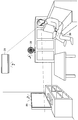
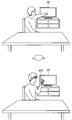
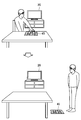
- FIG. 1 is a diagram for describing an overview of an information processing system according to an embodiment of the present disclosure.
- An information processing system includes an information processing apparatus 100 having a user aspect recognition function, a projection control function, a device control function, and a communication function, a projection device, an imaging device, and an operated device.
- the user mode recognition function is a function that recognizes the mode of the user's body.
- the projection control function is a function for controlling the mode of an image to be projected by the projection apparatus, the projection location of the image, and the like.
- the device control function is a function for controlling processing of the operated device.
- the communication function is a function for communicating information with a device or device outside the information processing apparatus 100. Therefore, the information processing apparatus 100 is connected via communication in accordance with an operation using the user's body for an image (hereinafter also referred to as an operation object) for operating the operated device to be projected on the projection apparatus. It is possible to control the operating device.
- the information processing apparatus 100 has an operated device selection function, an operation object mode control function, and an operation object movement function in addition to the above functions.
- the operated device selection function is a function for selecting an operated device to be operated from a plurality of operated devices.
- the operation object display function is a function for controlling the display mode of the displayed operation object.
- the operation object moving function is a function for controlling the movement of the displayed operation object.
- the information processing system 1 includes an information processing device 100, a projection imaging device 10, a display device 20, and an air conditioner 21.
- the information processing apparatus 100 is connected to the projection imaging apparatus 10, the display apparatus 20, and the air conditioner 21 via a network such as the Internet.
- the projection imaging apparatus 10 may be a separate projection apparatus and imaging apparatus.
- the information processing apparatus 100 selects the display device 20 and the air conditioner 21 as operated devices.
- the information processing apparatus 100 causes the projection imaging apparatus 10 to project an operation object for operating the selected display device 20 or air conditioner 21.
- the projection imaging apparatus 10 captures a range that the user enters, and transmits image information related to an image obtained by the imaging to the information processing apparatus 100.
- the information processing apparatus 100 recognizes a user operation from the form of the user's body that is recognized based on the received image information. Then, the information processing apparatus 100 moves the display location of the operation object in accordance with a user operation. Further, the information processing apparatus 100 controls processing of the display device 20 or the air conditioner 21 based on a user operation on the operation object.
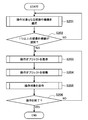
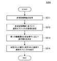
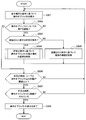
- FIG. 2 is a flowchart illustrating an outline of processing of the information processing system 1 according to an embodiment of the present disclosure.
- the information processing system 1 selects an operated device to be operated (step S201). Specifically, the information processing apparatus 100 selects an operated device to be operated from a plurality of operated device connected via communication.
- the information processing system 1 determines whether one or more operated devices are selected (step S202). Specifically, the information processing apparatus 100 determines whether one or more operated devices are selected as operation targets.
- the information processing system 1 displays an operation object (step S203). Specifically, the information processing apparatus 100 causes the projection imaging apparatus 10 to project an operation object for the operated device selected as the operation target.
- the information processing system 1 moves the operation object (step S204). Specifically, the information processing apparatus 100 moves the projection location of the operation object according to a user operation on the operation object to be projected.
- the information processing system 1 operates the operated device to be operated (step S205). Specifically, the information processing apparatus 100 causes the operated device corresponding to the operation object to execute processing in response to a user operation on the operation object to be projected.
- the information processing system 1 determines whether the operation has been completed (step S206). Specifically, the information processing apparatus 100 determines whether the operation of the operated device using the operation object is finished. If it is determined that the operation has ended, the information processing system 1 ends the display of the operation object.
- FIG. 3 is a block diagram schematically illustrating an example of a functional configuration of the information processing system 1 according to the first embodiment of the present disclosure.
- the information processing system 1 includes an information processing apparatus 100-1, a projection imaging apparatus 10, and a display apparatus 20 and an air conditioner 21 as operated devices.
- an information processing apparatus 100-1 the information processing apparatus 100-1
- a projection imaging apparatus 10 the information processing apparatus 100-1
- a display apparatus 20 and an air conditioner 21 the information processing apparatus 100-1
- functions of the information processing apparatus 100-1 and the projection imaging apparatus 10 will be described in detail.
- the information processing apparatus 100-1 includes a recognition unit 101, a device selection unit 102, a projection control unit 103, a device control unit 104, a communication unit 105, and a storage unit 106.
- the recognition unit 101 recognizes the mode of the user as the operation subject. Specifically, the recognition unit 101 recognizes the user's body mode based on the observation information. More specifically, the observation information is image information related to an image shown by the user, and the recognition unit 101 recognizes the form of the user's body by analyzing the image related to the image information. For example, the recognition unit 101 recognizes the user's face or eyes shown in the image, and recognizes the user's line of sight based on the recognized face or eye arrangement or shape. Note that the observation information may be measurement information related to the movement or position of the user, and the recognition unit 101 may recognize the form of the user's body based on the measurement information. As a form of the body, there is a visual aspect such as a line of sight or a visual field. The measurement information may be acquired from a sensor worn by the user or a sensor installed on an object existing around the user.
- the recognition unit 101 recognizes a user operation based on the recognized user mode. Specifically, the recognizing unit 101 recognizes an operation on the operated device based on the user's mode on the operation object projected by the projection control unit 103. For example, when the operation of touching the operation object is recognized, the recognition unit 101 recognizes that an operation on the operation object has been performed.
- the device selection unit 102 selects an operated device to be operated (hereinafter also referred to as an operation target device) based on the form of the user's body. Specifically, the device selection unit 102 selects an operation target device based on the form of the body toward the operated device of the user as the first device selection. For example, the device selection unit 102 selects an operation target device based on a visual aspect toward the user's operated device. Furthermore, the first device selection will be described in detail with reference to FIG. FIG. 4 is a diagram for describing an example of first device selection in which one operated device is selected in the information processing system 1 according to the present embodiment.
- the device selection unit 102 determines a device selection range based on line-of-sight information related to the user's line of sight recognized by the recognition unit 101. For example, the device selection unit 102 determines a range in real space corresponding to the user's field of view as illustrated in FIG. 4 as the device selection range based on the line-of-sight information provided from the recognition unit 101.
- the device selection range may be narrower than the estimated user field of view.
- the device selection unit 102 selects an operated device that is determined to be in the device selection range in accordance with the determination operation by the user. For example, when the recognition unit 101 recognizes the user's operation for determining the device selection range, the device selection unit 102 determines whether the operated device exists within the determined range. And the apparatus selection part 102 selects the to-be-operated apparatus determined to exist in the determined range, for example, the display apparatus 20 as shown in FIG. 4 as an operation target apparatus. Note that the position information of the operated device in the real space may be provided from the recognition unit 101 or may be provided from an external device.
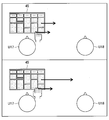
- the device selection unit 102 selects a plurality of operated devices as operation target device candidates (hereinafter also referred to as candidate devices). Furthermore, with reference to FIG. 5, the 1st apparatus selection in case a several to-be-operated apparatus is selected as a candidate apparatus is demonstrated in detail.
- FIG. 5 is a diagram for describing an example of first device selection in which a plurality of operated devices are selected in the information processing system 1 according to the present embodiment. Note that description of processing that is substantially the same as the processing described above is omitted.
- the device selection unit 102 determines a device selection range based on line-of-sight information related to the user's line of sight recognized by the recognition unit 101.
- the device selection unit 102 selects an operated device that is determined to be within the device selection range. For example, the device selection unit 102 determines whether the operated device exists within the determined range. The device selection unit 102 selects, as candidate devices, a plurality of operated devices that are determined to exist within the determined range, for example, the display device 20, the air conditioner 21, and the air blower 22 as illustrated in FIG. .
- the first device selection has been described as an example in which an operated device that actually exists in an area (that is, a device selection range) determined based on the form of the user's body has been described.
- a device to be operated associated with the device may be selected.
- the operated device can be selected even when the operated device is not directly visible.
- a tag associated with the operated device is arranged in the real space, and the device selection unit 102 selects the operated device associated with the tag that falls within the device selection range as a candidate device or an operation target device.
- a specific area in the real space is associated with the operated device, and the device selection unit 102 selects the operated device associated with the specific area that falls within the device selection range as a candidate device or an operation target device.
- the tag When the tag is provided, the user can make a first device selection after clearly recognizing the operated device.
- the tag when the specific area is provided, the tag can be omitted, and it is possible to reduce the effort or cost of advance preparation or linking change.
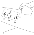
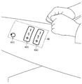
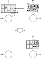
- the device selection unit 102 selects an operation target device from the candidate devices selected by the first device selection. Specifically, the device selection unit 102 selects, among the candidate devices selected by the first device selection, based on the user's selection operation for the selected object projected by the projection imaging apparatus 10 as the second device selection. Select the operation target device from. Furthermore, the second device selection will be described in detail with reference to FIG. FIG. 6 is a diagram for describing an example for describing a second device selection example in which an operation target device is selected based on an operation on a selected object in the information processing system 1 according to the present embodiment.
- selection object 31A, 32A, and 33A corresponding to each of the air blower 22, the display device 20, and the air conditioner 21 shown in FIG. 6 selected in the first device selection are selected by the projection imaging device 10, respectively. It is projected on the display area 30 of the object.
- the device selection unit 102 selects the selected candidate device as an operation target device. For example, when the operation of touching the selection object 32A is recognized by the recognition unit 101, the device selection unit 102 selects the display device 20 corresponding to the selected selection object 32A as the operation target device.
- the projection control unit 103 controls the projection of the projection imaging apparatus 10 as a display control unit. Specifically, the projection control unit 103 controls the projection of the selected object related to the candidate device selected by the first device selection. More specifically, the projection control unit 103 causes the projection imaging apparatus 10 to project a selection object indicating the candidate device selected by the first device selection. Further, the selected object will be described in detail with reference to FIGS. 6 and 7.
- FIG. 7 is a diagram for explaining an example of priority information in the information processing system 1 according to the present embodiment.
- the projection control unit 103 determines the mode of the selected object for the plurality of candidate devices based on the priority information.
- the priority information there is information determined based on the form of the body in the first device selection. More specifically, the projection control unit 103 determines the arrangement of the selected object based on the user's line of sight in the first device selection. For example, the projection control unit 103 determines the mode of the selected object according to the distance in the three-dimensional space from the user's line of sight to the candidate device in the first device selection. Specifically, the projection control unit 103, as shown in FIG.
- the distance d1 from the user's line of sight to the air blower 22, the distance d2 from the user's line of sight to the air conditioner 21, and the user's line of sight to the display device 20 The distance d3 is calculated. Then, the projection control unit 103 determines the arrangement of the selected objects in order from the shortest or longest calculated distance.
- the distance from the line of sight to the candidate device may be a distance in a two-dimensional space.
- the selected object may be arranged at a location closer to the user as the priority is higher, that is, as the calculated distance is shorter.
- the projection control unit 103 determines a location corresponding to the determination operation of the first device selection by the user as the projection location of the selected object. As a place according to the determination operation, there is a body part of the user specified by the determination operation. For example, when the tap operation as the device selection range determination operation in the first device selection is performed on the user's thigh, the projection control unit 103 determines the region 30 on the user's thigh as the projection location of the selected object. . Note that the projection control unit 103 may determine the display location of the selected object in accordance with the selection operation of the display location of the selected object that is different from the determination operation of the first device selection.
- the projection control unit 103 causes the projection imaging apparatus 10 to project the selected object in the determined manner at the determined projection location.
- the projection control unit 103 supplies the selected objects 31A, 32A, and 33A to the projection imaging apparatus 10 in the determined list format in the area 30 in the user's thigh as shown in FIG. Project.
- the selected object may be projected for the operated device related to the candidate device selected by the first device selection.
- the projection control unit 103 grasps an operated device that operates in cooperation with the candidate device, and projects the selected object for the grasped operation device on the projection imaging apparatus 10 together with the selected object for the candidate device.
- a selection object for a recording device, a sound output device, or a lighting device that operates in cooperation with the display device 20 may be projected.
- a selection object for an operated device having a function similar to the function of the candidate device may be projected. In this case, usability can be improved by projecting a selection object for a device that the user may desire to operate.
- the projection control unit 103 may control the notification of the operated device selected by the first device selection when the selected object is projected as the notification control unit. Specifically, the projection control unit 103 controls the projection indicating the association between the operated device selected by the first device selection and the selected object. Furthermore, with reference to FIG. 8, the notification of the operated device selected by the first device selection will be described in detail.
- FIG. 8 is a diagram illustrating an example of notification of the operated device selected by the first device selection in the information processing system 1 according to the present embodiment.
- the projection control unit 103 displays the association between each of the plurality of candidate devices selected by the first device selection and the place where the determination operation is performed. Is projected onto the projection imaging apparatus 10. Specifically, when it is recognized that the determination operation of the first device selection has been performed on the user's thigh, each of the display device 20, the air conditioner 21, and the blower device 22 and the user according to the determination operation An animation of an image (including simple light) with a line connecting the region 30 in the thigh as a trajectory is projected. For example, an animation that the image moves from the candidate device to the region 30 may be projected, and the selected object may be projected when the image reaches the region 30.
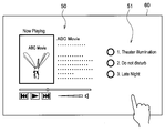
- the projection control unit 103 controls projection of the operation object for the operated device selected by the second device selection. Specifically, when a candidate device selection operation is recognized in the second device selection, the projection control unit 103 causes the projection imaging apparatus 10 to project an operation object for the selected candidate device. For example, when the selection operation on the selected object is recognized, the projection of the selected object is terminated, and the operation object may be projected on the place where the selected object was projected.
- the device control unit 104 controls the operated device. Specifically, the device control unit 104 controls processing of the operated device based on a user operation recognized by the recognition unit 101. For example, the device control unit 104 determines the processing of the display device 20 according to the operation of the operation object on the display device 20, and sends a processing execution request for requesting execution of the determined processing to the communication unit 105 to the display device 20. Send it.
- the communication unit 105 communicates with a device external to the information processing device 100-1. Specifically, the communication unit 105 transmits image information to the projection imaging apparatus 10 and receives image information from the projection imaging apparatus 10. In addition, the communication unit 105 transmits a process execution request to the display device 20 and the air conditioner 21. Note that the communication unit 105 may communicate using either a wired communication method or a wireless communication method.
- the storage unit 106 stores information used in processing of the information processing apparatus. Specifically, the storage unit 106 stores information used for analyzing observation information in the recognition processing by the recognition unit 101. Further, the storage unit 106 stores image information relating to an image to be projected on the projection imaging apparatus 10 by the projection control unit 103. Instead of storing information in the storage unit 106, information stored in an external device may be acquired via communication.
- the projection imaging apparatus 10 projects an image based on an instruction from the information processing apparatus 100-1. Specifically, the projection imaging apparatus 10 projects an image related to the image information provided from the information processing apparatus 100-1 toward a designated place.
- the projection imaging apparatus 10 may be a projector that can rotate the projection direction about two axes.
- the projection imaging device 10 may be a display device included in an omnidirectional projector, a hologram video device, or an object (for example, a table or a sofa) arranged around the user. Further, the projection imaging apparatus 10 may project different images simultaneously on a plurality of locations.
- the projection imaging apparatus 10 images the periphery of itself. Specifically, the projection imaging apparatus 10 images its surroundings at predetermined time intervals or in response to a request from the information processing apparatus 100-1. Then, the projection imaging apparatus 10 transmits image information relating to an image obtained by imaging to the information processing apparatus 100-1.
- the imageable range may be the same as the projectable range or may be wider than the projectable range.
- the imaging range may be made to follow the projection range.
- the imaging range may be plural.
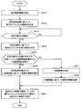
- FIG. 9 is a flowchart conceptually showing an example of the entire processing of the information processing system 1 according to this embodiment.
- the information processing system 1 estimates the form of the user's body (step S301). Specifically, the recognition unit 101 recognizes the form of the user's body using image information or the like.
- the information processing system 1 determines whether the first device selection determination operation has been performed (step S302). Specifically, the recognizing unit 101 determines the device selection range based on the recognized body form of the user. The recognizing unit 101 attempts to recognize the first device selection determination operation based on the recognized user's body aspect. The device selection unit 102 determines whether the recognition unit 101 has recognized the first device selection determination operation.
- the information processing system 1 determines whether the operated device has been selected (step S303). Specifically, when it is determined by the recognition unit 101 that the first device selection determination operation has been recognized, the device selection unit 102 determines whether one or more operated devices exist in the device selection range. .
- the information processing system 1 determines whether there are a plurality of selected operated devices (step S304). Specifically, the device selection unit 102 determines whether there are two or more operated devices in the device selection range.
- the information processing system 1 displays the selected object (step S305). Specifically, when it is determined that there are two or more operated devices, the device selection unit 102 selects the two or more operated devices as candidate devices. Then, the projection control unit 103 causes the communication unit 105 to transmit image information related to the selected object for the candidate device to the projection imaging apparatus 10. Then, the projection imaging apparatus 10 projects the selected object related to the received image information to the designated location. Details will be described later.
- the information processing system 1 determines whether the second device selection determination operation has been performed (step S306). Specifically, the recognizing unit 101 tries to recognize the determination operation of the second device selection. The device selection unit 102 determines whether the recognition unit 101 has recognized the second device selection determination operation.
- the information processing system 1 displays an operation object for the operated device (step S307). Specifically, when the recognition unit 101 determines that the second device selection determination operation has been recognized, the device selection unit 102 causes the communication unit 105 to transmit image information related to the operation object to the projection imaging apparatus 10. . Then, the projection imaging apparatus 10 projects the operation object related to the received image information instead of the selected object.
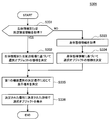
- FIG. 10 is a flowchart conceptually showing an example of the selected object display process of the information processing system 1 according to this embodiment.
- the information processing system 1 acquires the user's body form information (step S311). Specifically, the projection control unit 103 acquires information related to the form of the user's body recognized by the recognition unit 101.
- the information processing system 1 determines the mode of the selected object based on the body mode information (step S312). Specifically, the projection control unit 103 determines priority information based on the acquired body form information. Then, the projection control unit 103 determines the arrangement of the selected objects based on the priority information.
- the information processing system 1 determines the display location according to the determination operation for selecting the first device (step S313). Specifically, the projection control unit 103 determines the location where the first device selection determination operation is performed as the display location of the selected object.
- the information processing system 1 displays the selected object in the determined manner at the determined location (step S314).
- the projection control unit 103 causes the communication unit 105 to transmit the image information related to the selected objects in the determined arrangement to the projection imaging apparatus 10 together with the projection location instruction.
- the projection imaging apparatus 10 projects the selected object related to the received image information onto the designated location.
- the information processing system 1 that is, the information processing apparatus 100-1, is configured to perform the first operation based on information in which the body aspect toward the operation target subject to operation is estimated.
- the display of the selected object related to the operated device selected by the device selection is controlled.
- the information processing apparatus 100-1 controls the operated device selected by the second device selection based on the information related to the selection operation of the operating subject with respect to the selected object.
- the first interface for operating the operated device in the vicinity or the second interface for remotely operating the operated device has been mainly provided.
- the user has to move to the operated device.
- the NUI operation such as the gesture operation in the second interface
- the remote controller operation of the second interface when there are a plurality of operated devices, it takes time to find a remote controller corresponding to the operated device.
- the candidate of the operated device selected by the first device selection based on the form of the user's body is presented to the user, and the user selects the operated device from the candidates. be able to. Therefore, first, the user does not have to move to the operated device. Further, when the user selects an operation target from the presented operated device candidates, erroneous selection of the operated device can be suppressed, and re-selection of the operated device can be prevented. Further, by operating the operated device based on the selection of the selected object, it is possible to operate the operated device without a specific device such as a remote controller, and it is possible to suppress the trouble of searching for the remote controller. . Therefore, it is possible to reduce the burden on the user regarding the selection of the operated device that the user desires to operate.
- the selection object includes an object indicating the operated device selected by the first device selection. For this reason, the candidate apparatus selected by 1st apparatus selection is specified, and the user can select the to-be-operated apparatus which he intends more reliably.
- the selected object is displayed so as to be viewed in a manner based on the priority information.
- the first device selection a plurality of candidate devices are selected, but there is generally only one operated device that the user actually wants to operate. Therefore, the operability of the selected object can be improved by projecting the selected object on the projection imaging apparatus 10 so that a desired operated device can be easily selected.
- the aspect of the selection object controlled based on the priority information includes the arrangement of the selection object. Therefore, the user can intuitively grasp the operated device that the user desires to operate. Therefore, the operability of the selected object can be improved.
- the priority information includes information determined based on information on the body aspect in the first device selection.
- the operated device that the user desires to operate has already been determined for the user at the time of the first device selection. Therefore, the selection object for the desired operated device is determined by determining the mode of the selected object according to the high possibility of being the desired operated device estimated from the body mode in the first device selection. Can be more easily selected, and the operability can be further improved.
- the information processing apparatus 100-1 controls the display of the operation object for the operated device selected by the second device selection. For this reason, a desired operated device can be operated according to the user's intention. Therefore, it is possible to improve the usability in the operation of the selected operated device.
- the selected object is displayed at a location corresponding to the determination operation in response to the determination operation of the first device selection by the operation subject. For this reason, it is possible to easily select a desired device to be operated as a candidate device by performing the first device selection according to the user's intention. Further, the operability of the selected object can be improved by projecting the selected object to a place intended by the user.
- the place corresponding to the determination operation includes the body part of the operation subject specified by the determination operation. For this reason, by projecting the selection object onto the user's body, the selection object can be projected to a place where the user can easily operate even when the projection space of the selection object is not secured around the user. When the projection location is tracked, the selected object moves even if the user moves, so that the projected selected object can be operated continuously.
- the information processing apparatus 100-1 controls notification of the operated device selected by the first device selection when the selected object is displayed. For this reason, the user can confirm the candidate device selected by the first device selection. For example, when the desired operated device is not selected, the user can redo the first device selection. Therefore, erroneous selection of the operation target device can be suppressed, and the selection of the operation target device can be made more efficient.
- the notification includes a display output indicating the association between the selected operated device and the selected object. For this reason, while confirming the selected candidate apparatus, a user can be guide
- the user's line of sight can be guided from the operated device to the selected object. Therefore, the user can be smoothly guided from the first device selection to the second device selection, and the operation target device can be easily selected.
- the body aspect includes a visual aspect of the operation subject, and an operated device that is determined to enter at least a part of the view of the operation subject is selected by the first device selection.
- the operated device can be selected without moving a body part such as a user's hand or foot. Therefore, the user can select and operate an operated device desired to be operated while performing a separate work or the like.
- the user's line of sight generally faces the operated device. Therefore, by performing the first device selection based on the visual aspect, it is possible to increase the possibility that the candidate device is an operated device that is desired to be operated.
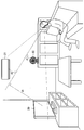
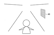
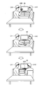
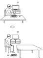
- the information processing system 1 may perform the first device selection based on another body aspect. Specifically, the information processing apparatus 100-1 performs the first device selection based on the user's posture. More specifically, in the first device selection, the device selection unit 102 selects an operated device that is determined to enter an area determined from the user's posture as an operation target device or a candidate device. Furthermore, the process of this modification is demonstrated with reference to FIG. FIG. 11 is a diagram for describing an example of first device selection in the information processing system 1 according to the first modification of the present embodiment.
- the recognition unit 101 recognizes at least a part of the user's body based on image information and the like. For example, the recognition unit 101 recognizes the orientation of the user's face or body shown in the image based on the image information relating to the three-dimensional image received from the projection imaging apparatus 10.
- the device selection unit 102 determines a device selection range based on the user's posture. For example, the device selection unit 102 determines a device selection range as shown in FIG. 11 based on the recognized user's face or body orientation.
- the device selection unit 102 selects an operated device that falls within the determined device selection range as an operation target device or a candidate device. For example, the device selection unit 102 selects the display device 20 that falls within the determined device selection range as shown in FIG. 11 as the operation target device. In addition, when a plurality of operated devices enter the determined device selection range, the plurality of operated devices are selected as candidate devices.
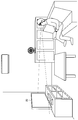
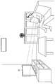
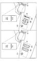
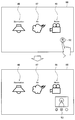
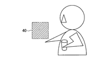
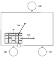
- the information processing apparatus 100-1 may perform the first device selection based on the user's movement. Specifically, the device selection unit 102 selects, as the operation target device or the candidate device, the operated device that is determined to enter the region determined from the user's movement in the first device selection. Furthermore, with reference to FIG. 12, the process of another example of the present modification will be described.
- FIG. 12 is a diagram for explaining another example of the first device selection in the information processing system 1 according to the first modification of the present embodiment.
- the recognition unit 101 recognizes a user's movement based on image information and the like. For example, the recognizing unit 101 recognizes a user's gesture or action reflected in an image based on image information relating to a three-dimensional image received from the projection imaging apparatus 10.
- the gesture includes, for example, a motion of drawing a circle, double tap, flick, applause, or contact with an object.
- the device selection unit 102 determines a device selection range based on the user's movement. For example, when it is recognized that the hand toward the operated device is grasped as shown in FIG. 12, the device selection unit 102 determines the device selection range as shown in FIG. 12 based on the hand. To do.
- the device selection unit 102 selects an operated device that falls within the determined device selection range as an operation target device or a candidate device. Specifically, the device selection unit 102 selects a display device 20 that falls within the determined device selection range as shown in FIG. 12 as an operation target device. In addition, when a plurality of operated devices enter the determined device selection range, the plurality of operated devices are selected as candidate devices.
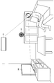
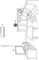
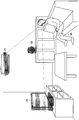
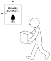
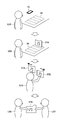
- the information processing apparatus 100-1 may perform the first device selection based on the user's utterance. Specifically, the device selection unit 102 selects, as the operation target device or the candidate device, the operated device that is determined to enter the region determined from the user's utterance in the first device selection. Furthermore, with reference to FIG. 13, the processing of another example of this modification will be described.
- FIG. 13 is a diagram for explaining another example of the first device selection in the information processing system 1 according to the first modification of the present embodiment.
- the recognition unit 101 recognizes the user's utterance based on the voice information. For example, the recognizing unit 101 recognizes the presence / absence of the user's utterance or the content of the utterance based on voice information received from a voice input device provided separately in the information processing system 1.
- the device selection unit 102 determines a device selection range based on the user's utterance. For example, when the user's utterance content “living room” as shown in FIG. 13 is recognized, the device selection unit 102 determines the living room as the device selection range.
- the device selection unit 102 selects an operated device that falls within the determined device selection range as an operation target device or a candidate device. Specifically, the device selection unit 102 selects the determined device selection range, that is, the display device 20, the air conditioner 21, and the air blower 22 that exist in the living room as candidate devices. If there is only one operated device in the determined device selection range, the operated device is selected as the operation target device.
- the body of the operating subject includes the posture of the operating subject and is determined to enter the region determined from the posture of the operating subject.
- the operating device is selected by the first device selection.
- the user When the user operates the operated device, the user generally takes a posture corresponding to the operated device. Therefore, an appropriate candidate device can be selected in the first device selection by selecting a candidate device according to the user's posture.
- the processing load can be reduced as compared with the first device selection based on the visual aspect. Therefore, the responsiveness can be improved.
- the body of the operating subject includes the motion of the operating subject, and the operated device that is determined to enter the region determined from the motion of the operating subject is the first It is selected by selecting one device. Therefore, by selecting a candidate device according to the user's explicit movement with respect to the first device selection, it is possible to realize the first device selection that is more in line with the user's intention. Therefore, the operability in selecting the first device can be further improved.
- the body of the operating subject includes the utterance of the operating subject, and the operated subject is determined to enter the region determined from the utterance of the operating subject.
- a device is selected by a first device selection. For this reason, the user can select the operated device without moving the body. Therefore, the user can select and operate an operated device desired to be operated while performing a separate work or the like without further turning his / her line of sight.
- the first device selection may be performed based on the form of the object operated by the user instead of the user's body.
- the information processing apparatus 100-1 determines the device selection range from the form of the object operated by the user, and operates to enter the device selection range in response to the first device selection determination operation on the object. Select the device.
- the object operated by the user may be a device such as a smartphone, and the recognition unit 101 recognizes the orientation of the smartphone.
- the device selection unit 102 determines a device selection range according to the recognized orientation of the smartphone.
- the recognition unit 101 recognizes an operation on the smartphone, for example, a lower flick operation.
- the device selection unit 102 selects the operated device within the determined device selection range.
- the recognition unit 101 may acquire information on the form of the object from the object or another external device.
- the user's aspect is the aspect for selecting the first device as compared to the user's physical aspect. Therefore, the possibility that the first device selection process malfunctions can be suppressed.
- the information regarding the aspect of the said object is obtained from the said object, the aspect of an object can be recognized more correctly. Therefore, it is possible to improve the accuracy of the first device selection process.
- the selected object may be displayed regardless of the first device selection determination operation.
- the projection control unit 103 determines the body of the operation subject having a displayable area (hereinafter also referred to as a projectable region) so that the selected object is visually recognized by the operation subject or the periphery of the operation subject. Then, the selected object is projected on the projection imaging apparatus 10 at the determined place.
- the projection control unit 103 searches for a projectable area so that the selected object is visually recognized by the user.
- the projectable area may be an area having the largest area in the user's body or the user's periphery. Further, the projectable area may be determined according to the degree of unevenness of the surface, the color of the surface, the texture, or the presence or absence of a pattern.
- the projectable area may be a plane or a surface with unevenness within an allowable range, a surface with color or texture uniformity within an allowable range, or a surface that does not include a pattern.
- a white plane may be preferentially selected as the projectable region.
- FIG. 14 is a flowchart conceptually showing an example of selected object display processing of the information processing system 1 according to the second modification of the present embodiment. Note that description of processing that is substantially the same as the processing described above is omitted.
- the information processing system 1 acquires body form information (step S321), and determines the form of the selected object based on the acquired body form information (step S322).
- the information processing system 1 determines a display location according to the displayable area (step S323). Specifically, the projection control unit 103 searches for a projectable area in the user's body or in the vicinity of the user. When a region satisfying the condition is found, the projection control unit 103 determines the region as a projectable region.
- the information processing system 1 displays the selected object in the determined manner at the determined location (step S324).
- the projection control unit 103 causes the projection imaging apparatus 10 to project the selected object onto a region of the user's body or the user's periphery determined as the projectable region.
- the selected object is the body of the operating subject having a displayable area so that the selected object is visually recognized by the operating subject or the periphery of the operating subject. Is displayed. For this reason, it is possible to project the selected object without the first device selection determination operation by the user. Therefore, it is possible to perform the first device selection even in a situation where the user cannot perform the determination operation, for example, during work.
- the display mode of the selected object may be another mode.
- the display location of the selected object may be another location.
- the selected object may be displayed on the display unit designated by the first device selection determination operation.
- the projection control unit 103 displays the selected object on the display device.
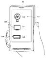
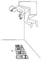
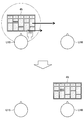
- FIG. 15 is a diagram illustrating a display example of the selected object in the information processing system 1 according to the third modification of the present embodiment.
- the recognition unit 101 recognizes the operation destination of the first device selection determination operation. For example, when the determination operation for the first device selection is recognized, the recognition unit 101 recognizes the operation destination of the determination operation.
- the projection control unit 103 determines whether the display device can be controlled. For example, when the recognized operation destination is the smartphone 70 as illustrated in FIG. 15, the projection control unit 103 determines whether at least the display function of the smartphone 70 can be controlled.
- the projection control unit 103 causes the display device to display the selected object.
- the projection control unit 103 causes the communication unit 105 to transmit image information related to the selected object to the smartphone 70.
- the smartphone 70 displays the selection objects 31A to 33A on the display unit based on the received image information.
- the aspect of the selected object corresponding to the priority information may be another aspect.
- the size of the selected object may be determined according to the priority information.
- the projection control unit 103 determines the size of the selected object based on the body aspect in the first device selection.
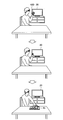
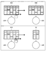
- FIG. 16 is a diagram illustrating another example of the display of the selected object in the information processing system 1 according to the third modification of the present embodiment.
- the projection control unit 103 determines the size of the selected object according to the distance in the three-dimensional space from the user's line of sight to the candidate device in the first device selection. For example, the projection control unit 103 calculates the distances from the user's line of sight to the display device 20, the air conditioner 21, and the blower 22, respectively. Then, the projection control unit 103 determines the size so that the smaller the calculated distance, the larger the size of the selected object. Specifically, as shown in FIG. 16, the projection control unit 103 sets the size of the selected object 32B for the display device 20 having the shortest calculated distance among the candidate devices to the largest size among the candidate devices. To decide. Further, as shown in FIG. 16, the projection control unit 103 determines the size of the selected object 31B for the blower 22 having the longest calculated distance among the candidate devices as the smallest size among the candidate devices. To do.
- the place corresponding to the determination operation for the first device selection includes the display unit specified by the determination operation. For this reason, the visibility of a selection object is securable by displaying a selection object on a display part. In particular, when the selected object is projected, it is difficult to project the selected object when there is an object between the projection location and the projection apparatus, and therefore the configuration of this modification is significant.
- the mode of the selected object controlled based on the priority information includes the size of the selected object. For this reason, it is possible to make it easier to grasp the operated device that the user desires to operate. Therefore, the operability of the selected object can be improved.
- the priority information related to the display mode of the selected object may be other information.
- the priority information may be information determined based on the biological information of the operating subject. More specifically, the biological information includes information related to the user's pulse, body temperature, sweating, brain waves, and the like, and the projection control unit 103 estimates an operated device that the user desires to operate from the biological information. Then, the projection control unit 103 determines an arrangement or size in which the selected objects for the estimated operated device are easily selected. For example, when the user's body temperature is lower than normal heat, that is, when it is estimated that the user feels cold, the selected objects are projected in an arrangement or size in which the selected objects for candidate devices such as air conditioners or heating devices are easily selected. Is done.
- the priority information may be information determined based on information related to the surrounding environment of the operating subject (hereinafter also referred to as surrounding environment information).
- the surrounding environment information includes information related to temperature, humidity, illuminance, noise, and the like, and the projection control unit 103 estimates an operated device that the user desires to operate from the surrounding environment information. For example, when the volume of noise is higher than a threshold value, that is, when it is estimated that the user feels noisy, the selection objects are arranged or sized so that the selection objects for the candidate devices such as the video playback device or the sound output device are easily selected. Projected.
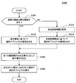
- FIG. 17 is a flowchart conceptually showing an example of selected object display processing of the information processing system 1 according to the fourth modification of the present embodiment. Note that description of processing that is substantially the same as the processing described above is omitted.
- the information processing system 1 determines whether biometric information or surrounding environment information has been acquired (step S331). Specifically, the projection control unit 103 determines whether biological information or surrounding environment information has been acquired.
- the biological information may be acquired via the communication unit 105, and the surrounding environment information may be acquired via the communication unit 105 or may be generated in the recognition process of the recognition unit 101.
- the information processing system 1 determines the mode of the selected object based on the biological information or the surrounding environment information (step S332). Specifically, the projection control unit 103 estimates, from the candidate devices, the operated device that the user desires to operate from the biological information or the surrounding environment information for each candidate device. Then, the projection control unit 103 determines the mode of the selected object for the candidate device estimated to be the operation target device that is desired to be operated as a mode that can be easily selected.
- the information processing system 1 acquires the body mode information (step S333), and the mode of the selected object based on the acquired body mode information. Is determined (step S334).
- the information processing system 1 determines the display location according to the first device selection determination operation (step S335), and displays the selected object in the determined manner at the determined location (step S336).
- the priority information may be information determined based on information related to past operation of the operated device.
- the projection control unit 103 acquires the operation history of the user's past operated device recognized by the recognition unit 101 from the storage unit 106, and selects the operated device that the user desires to operate from the operation history. presume. For example, based on the time zone and place where the operation grasped from the operation history was performed, the operation order of the operated device, the current time zone, the user's location, and the selected candidate device, the user regarding the candidate device May be desired to operate. Then, the higher the possibility of being estimated, the more the selected objects are projected in an arrangement or size in which the selected objects are more easily selected.
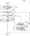
- FIG. 18 is a flowchart conceptually showing another example of the selected object display process of the information processing system 1 according to the fourth modification example of the present embodiment. Note that description of processing that is substantially the same as the processing described above is omitted.
- the information processing system 1 determines whether an operation history of the operated device exists (step S341). Specifically, the projection control unit 103 determines whether the operation history of the operated device exists in the storage unit 106. Note that the presence / absence of the operation history of the candidate device in the operation history of the operated device may be determined.
- the information processing system 1 determines the mode of the selected object based on the operation history (step S342). Specifically, the projection control unit 103 estimates the possibility that the user wishes to operate the device based on the operation history for each candidate device. Then, the projection control unit 103 determines the mode of the selected object for the candidate device such that the more likely the device to be operated is, the more easily the device to be operated is selected.
- the information processing system 1 acquires the body mode information (step S343), and the mode of the selected object based on the acquired body mode information. Is determined (step S344).
- the information processing system 1 determines the display location according to the first device selection determination operation (step S345), and displays the selected object in the determined manner at the determined location (step S346).
- the priority information includes information determined based on the biological information of the operating subject or information related to the surrounding environment of the operating subject. For this reason, the aspect of the selection object according to a user's physical condition or bodily sensation can be determined. Therefore, it becomes easier to select a selected object for a desired operated device, and operability can be further improved.
- the priority information includes information determined based on information related to past operation of the operated device. For this reason, the aspect of the selection object according to the user's operation tendency or habit can be determined. Therefore, it is highly possible that the selected object that is easily displayed and selected is a selected object for a desired operated device, and the operability can be further improved.
- the projection control unit 103 may determine the mode of the selected object using a combination of at least two or more of the user's body mode information, biological information, surrounding environment information, and operation history. Further, the priority information may be converted into a score or the like, and the selected object may be displayed in a manner in which a candidate device with a higher score is more easily selected.
- notification of candidate devices may be realized by other methods. Specifically, when displaying the selected object, the projection control unit 103 causes the projection imaging apparatus 10 to perform a projection in which the operated device selected by the first device selection, that is, the candidate device or the periphery of the candidate device stands out. Furthermore, with reference to FIG. 19, the example of the notification of the candidate apparatus in this modification is demonstrated.
- FIG. 19 is a diagram illustrating an example of notification of the operated device selected by the first device selection in the information processing system 1 according to the fifth modification of the present embodiment.
- the projection control unit 103 emits light from each of the plurality of candidate devices selected by the first device selection or each of the plurality of candidate devices.
- the projection imaging apparatus 10 is caused to perform a projection that is visually recognized. For example, when it is recognized that the determination operation for selecting the first device has been performed, the projection control unit 103 emits light from each of the display device 20, the air conditioner 21, and the blower 22 as shown in FIG. Thus, the visual effect visually recognized by the user is projected on the projection imaging apparatus 10.
- An image indicating a candidate device such as an arrow may be projected instead of light emission.
- the information processing apparatus 100-1 may cause the candidate device to emit light.
- the device control unit 104 causes the communication unit 105 to transmit a light emission request addressed to the candidate device.
- the candidate device that has received the light emission request causes its light emitter to emit light for a predetermined period based on the light emission request. In this case, since the candidate device itself emits light, the load of the projection process can be reduced compared to the case where projection is used.
- the projection control unit 103 may cause the projection imaging apparatus 10 to perform projection indicating the location of the candidate device in the selected object. Specifically, an image indicating the location of the candidate device may be displayed in the display area of the selected object.
- FIG. 20 is a diagram illustrating another example of notification of the operated device selected by the first device selection in the information processing system 1 according to the fifth modification example of the present embodiment.
- the projection control unit 103 causes the projection imaging apparatus 10 to project the selected object having an image indicating the location of the candidate device. For example, when it is recognized that the determination operation of the first device selection has been performed, the projection control unit 103 indicates the location of each of the blower device 22, the display device 20, and the air conditioner 21 as illustrated in FIG. The selected objects 31C, 32C, and 33C having images such as are projected onto the area 30 by the projection imaging apparatus 10.
- the notification of the candidate device may be an audible notification.
- the device control unit 104 may control sound output from a region where the selected operated device enters.
- FIG. 21 is a diagram showing another example of notification of the operated device selected by the first device selection in the information processing system 1 according to the fifth modification of the present embodiment.
- the device control unit 104 causes the communication unit 105 to transmit a sound output request addressed to the candidate device if the candidate device has a sound output function.
- Each of the candidate devices that have received the sound output request outputs a sound as shown in FIG. 21 based on the sound output request.
- the output sound may be simple sound, music or voice. Further, the output sound may be different for each operated device, or may be the same. Further, when the operated device has a function of adding directivity to the sound output, the sound may be output toward the user.
- the candidate device has a sound output function.
- the information processing system 1 uses a phenomenon such as reflection of sound output from a separately provided sound output device, You may make a user perceive as if a candidate apparatus is outputting sound.
- the notification of the candidate device includes a display output in which the candidate device or the periphery of the candidate device stands out. Therefore, the user can grasp at a glance the operated device selected as the candidate device. Therefore, the user can determine at a glance whether the operated device is selected as intended by the user, and it is possible to quickly perform reselection even if an erroneous selection occurs in the first device selection. .
- the notification of the candidate device includes a display output indicating the location of the candidate device in the selected object. Therefore, the user can confirm the operated device selected as the candidate device on the operation object. Therefore, the user can suppress the occurrence of erroneous selection by checking before selecting whether the object is a selected object for a desired operated device. For example, when a plurality of the same type of operated devices are selected as candidate devices, it may be difficult to determine only by the selected object. However, since the location of the candidate device is presented to the user, the user can select a desired operated device even in this case.
- the notification of the candidate device includes sound output from the area where the candidate device enters. For this reason, the user can aurally confirm the operated device selected as the candidate device. Therefore, even when the line of sight cannot be directed to the candidate device or the selected object, the candidate device can be grasped and usability can be improved.
- Second Embodiment of Present Disclosure (Display of Operation Object)>
- the first embodiment of the present disclosure has been described.
- a second embodiment of the present disclosure will be described.
- an embodiment of the operation object aspect control function described above in the information processing system 1 will be mainly described.
- the recognition unit 101 recognizes the body state of the operation subject of the operated device. Specifically, the recognizing unit 101 recognizes the posture of the user as the body aspect, and generates body state information related to the recognized posture of the user. Note that the details are substantially the same as the function of the recognition unit 101 of the first embodiment, and a description thereof will be omitted.
- the recognition unit 101 recognizes a predetermined operation of the operation subject. Specifically, the recognizing unit 101 recognizes an operation object display instruction operation by the user.
- the display instruction operation of the operation object may be a touch operation, a tap operation, a pointing operation, or the like.
- the projection control unit 103 controls display of the operation object for the operated device as a display control unit. Specifically, the projection control unit 103 controls the complexity of the operation object for the operated device that is visually recognized so as to exist in the real space, based on the recognized body aspect of the operation subject. For example, the projection control unit 103 causes the projection imaging apparatus 10 to project an operation object that is visually recognized with complexity according to the posture of the user recognized by the recognition unit 101. Furthermore, the display control of the operation object will be described with reference to FIGS.
- FIG. 22 is a diagram illustrating an example of display control of the operation object in the information processing system 1 according to the present embodiment.
- FIG. 23 is a diagram illustrating another example of display control of the operation object in the information processing system 1 according to the present embodiment.
- the recognition unit 101 recognizes the user's posture. For example, when the display instruction operation of the selected object by the user is recognized, the recognition unit 101 recognizes the user's posture.
- the predetermined operation may be a selection operation for selecting a second device in the first embodiment.
- the projection control unit 103 determines an operation object associated with a predetermined motion target as a display target. Specifically, the projection control unit 103 determines, as a display target, an operation object associated with the operation destination of the recognized selection object display instruction operation. For example, when it is recognized that the tap operation as the display instruction operation for the selected object has been performed on the user's thigh, the projection control unit 103 determines the operation object corresponding to the user's thigh as a display target. .
- the operation object determined as the display target may be an operation object for the operation target device.
- the projection control unit 103 determines the complexity of the operation object according to the recognized user posture.
- the complexity of the operation object includes display complexity or operation complexity. For example, when the upper body of the user sitting as shown in the right diagram of FIG. 22 is tilted backward by a predetermined amount (in a so-called lean-back state), the projection control unit 103 is shown in the right diagram of FIG. As shown, the display amount of the operation object is reduced or the operation object that is easy to operate is selected as compared with the case where the user is sitting with the upper body tilted forward (in a so-called lean forward state). Thereby, the complexity of the operation object can be controlled according to whether the user is in a relaxed state.
- the complexity of the operation object can be controlled in accordance with the degree of concentration of the user on the operation of the operated device. This is because, for example, when the user is in a leanback state, the user is in a relaxed state, and it is considered that a fine operation of the operated device is not desired.
- the projection control unit 103 determines a place corresponding to the user's mode as a display place of the operation object. Specifically, the projection control unit 103 determines a place corresponding to a predetermined action performed by the user as a display place of the operation object. More specifically, the display location of the selected object may be the user's body. For example, when the tap operation on the user's thigh is recognized, the projection control unit 103 determines the area 40 on the user's thigh as shown in the left diagrams of FIGS. 22 and 23 as the display area of the operation object.
- the projection control unit 103 causes the projection imaging apparatus 10 to project the operation object with the complexity determined at the determined location. For example, when the user is in a leanback state, the projection control unit 103 transfers the operation objects 41A, 42A, and 43A as shown in the right diagram of FIG. 22 to the region 40 in the user's thigh to the projection imaging apparatus 10. Project.
- the operation object 41A is an object that provides operations for starting and ending the display device.
- the operation object 42A is an object that provides an operation for changing a channel.
- the operation object 43A is an object that provides an operation for changing the volume.
- the projection control unit 103 projects the operation objects 41B, 42B, and 43B as shown in the right diagram of FIG. 23 onto the region 40 in the user's thigh. 10 is projected.
- the operation objects 41B, 42B, and 43B provide substantially the same operations as the operation objects 41A, 42A, and 43A, respectively.
- the operation object 42B is accompanied by, for example, a thumbnail related to the change destination channel.
- the operation object 43B does not change the volume one step at a time, but can arbitrarily change the volume by moving the slide bar.
- FIG. 24 is a flowchart conceptually showing an example of processing of the information processing system 1 according to this embodiment. Note that description of processes that are substantially the same as the processes in the first embodiment will be omitted.
- the information processing system 1 acquires body form information (step S401), and determines the complexity of the operation object based on the body form information (step S402). Specifically, when the recognition unit 101 recognizes a user's predetermined motion, the projection control unit 103 determines an operation object to be projected from the target of the predetermined motion. Then, the projection control unit 103 determines the complexity of display or operation of the determined operation object based on the form of the body when the predetermined motion is recognized.
- the information processing system 1 determines the display location of the operation object based on the body form information (step S403). Specifically, the projection control unit 103 determines a location corresponding to a predetermined user action recognized by the recognition unit 101 as a display location of the operation object.
- the information processing system 1 displays the operation object having the determined complexity at the determined location (step S404).
- the projection control unit 103 causes the projection imaging apparatus 10 to project the selected object having the determined complexity to the determined location.
- the information processing system 1 that is, the information processing apparatus 100-2 obtains information on the body aspect of the operation subject of the operated device, Based on such information, the complexity of the operation object for the operated device that is visually recognized so as to exist in the real space is controlled.
- the displayed virtual object may be different from the virtual object desired by the user. For example, even if the user desires a detailed operation or a rough operation, if the same virtual object is displayed, the operability may be reduced or the operation burden may be increased.
- the present embodiment it is possible to display an operation object having a complexity corresponding to the user's situation estimated from the user's body aspect. For this reason, it is possible to increase the possibility that operation objects suitable for the operation desired by the user are displayed in each situation of the user. Therefore, it is possible to suppress the variation of the user satisfaction with respect to the operation object according to the user situation.
- the body aspect includes the posture of the operation subject, and the operation object is displayed so as to be visually recognized with complexity according to information relating to the posture of the operation subject.
- the degree of concentration with respect to the user's operation is generally reflected in the posture of the user. Therefore, the operability of the operation object can be improved by controlling the complexity of the operation object according to the degree of concentration with respect to the operation for which the posture of the user is estimated.
- the operation object is displayed so as to be visually recognized by the body of the operation subject. For this reason, by projecting the operation object onto the user's body, the operation object can be projected to a place where the user can easily operate even when the projection space of the operation object is not secured around the user. Further, when the projection location is tracked, the operation object moves even if the user moves, so that the projected operation object can be operated continuously.
- the operation object is displayed at a location corresponding to the body of the operation subject. For this reason, by controlling the display location of the operation object in accordance with the mode of the user, it is possible to improve the operability of the operation object as compared to the case where the operation object is fixedly displayed at a predetermined location. .
- the body aspect of the operation subject includes a predetermined action of the operation subject, and the operation object is displayed at a place corresponding to the predetermined action. For this reason, it is possible to display the operation object at a place according to the user's intention. Therefore, it is possible to improve the usability for displaying the operation object.
- the operation object includes an operation object associated with the target of the predetermined action. For this reason, the user can select the operation object of the operated device desired to be operated by selecting the target of the predetermined operation. Therefore, it is possible to omit the process related to the display of the operation object as compared with the case where the operated device is selected based on a separate operation.
- the information processing system 1 may control the complexity of the operation object based on information related to other body aspects.
- the information processing apparatus 100-2 causes the projection imaging apparatus 10 to project the operation object with complexity according to the biological information of the operation subject.
- biometric information includes information related to the user's pulse, body temperature, sweating, brain waves, and the like.
- FIG. 25 is a diagram illustrating an example of display control of the operation object in the information processing system 1 according to the first modification of the present embodiment.
- the projection control unit 103 acquires biological information when an operation object display instruction operation is performed. For example, when the recognizing unit 101 recognizes an operation object display instruction operation by the user, the projection control unit 103 acquires information on the pulse and body temperature as the biological information of the user.
- the biometric information is acquired by the user as shown in FIG. 25 from the external device 80 that generates biometric information via the communication unit 105. Note that the biological information may be acquired at predetermined time intervals.
- the projection control unit 103 causes the projection imaging apparatus 10 to project the operation object with complexity determined based on the biological information.
- the projection control unit 103 causes the projection imaging apparatus 10 to display the operation object with complexity based on whether the acquired information about the pulse and the body temperature is equal to or greater than the threshold. Specifically, when both the pulse and the body temperature are less than the threshold value, the user is considered to be in a relaxed state, and the operation objects 41A to 43A whose display contents and operation functions are simple as shown in the left diagram of FIG. Is projected.
- the user is considered to be in a tension state, and the operation objects 41B to 43B whose display contents and operation functions are complicated as shown in the right diagram of FIG. Is projected.
- the information processing apparatus 100-2 causes the projection imaging apparatus 10 to project the operation object with complexity according to information related to the action of the operation subject (hereinafter also referred to as action information).
- action information information related to the action of the operation subject
- the user's behavior includes behavior not involving movement such as cooking or reading, and behavior involving movement such as walking, cycling or transportation.
- FIG. 26 is a diagram illustrating another example of the display control of the operation object in the information processing system 1 according to the first modification of the present embodiment.
- the projection control unit 103 acquires action information when an operation object display instruction operation is performed. For example, when the recognizing unit 101 recognizes the display instruction operation of the operation object by the user, the projection control unit 103 acquires the action information related to the transportation of the user as shown in FIG. To do.
- the projection control unit 103 causes the projection imaging apparatus 10 to project the operation object with complexity based on the behavior information. For example, when the behavior information related to transportation is acquired, the projection control unit 103 causes the projection imaging apparatus 10 to project the operation object 44 indicating that the operation unit as illustrated in FIG. In this case, the complexity of the operation is simpler than that of manual input, and the user can operate the operated device even during transportation that is not available.
- the information related to the body of the operation subject includes the biological information of the operation subject, and the operation object corresponds to the biological information of the operation subject. It is displayed so as to be visually recognized with complexity. Therefore, it is possible to determine the complexity of the operation object according to whether the user is in a relaxed state or in a tension state, in other words, according to the degree of concentration on the operation. Therefore, the complexity of the operation object is matched to the user's state, so that it is possible to reduce the user's discomfort or stress on the operation object.
- the body aspect of the operation subject includes the action of the operation subject, and the operation object is displayed so as to be visually recognized with complexity according to information related to the action subject's action. For this reason, the operation object of the complexity suitable for a user's action is displayed, and the user can operate an operation object smoothly, without preventing action.
- the information processing system 1 may control the complexity of the operation object based on information different from the body aspect information.
- the information processing apparatus 100-2 controls the complexity of the operation object based on information for specifying the operation subject.
- the projection control unit 103 controls the complexity of the operation object based on information that identifies the user (hereinafter also referred to as user identification information).
- FIG. 27 is a diagram illustrating an example of display control of the operation object in the information processing system 1 according to the second modification of the present embodiment.
- the projection control unit 103 acquires user specifying information when an operation object display instruction operation is performed. For example, when the recognition unit 101 recognizes an operation object display instruction operation by the user, the projection control unit 103 acquires face recognition information as the user specifying information of the user.
- the face recognition information is obtained by the face recognition process of the recognition unit 101 based on the image information related to the image shown by the user. For example, the users U1 and U2 as shown in FIG. 27 are recognized, and the face recognition information concerning the users U1 and U2 is acquired.
- the user identification information may be information such as an ID (Identifier) or a name instead of the face recognition information.
- the projection control unit 103 causes the projection imaging apparatus 10 to project the operation object with the complexity determined based on the user specifying information.
- the projection control unit 103 causes the projection imaging apparatus 10 to display the operation object with complexity corresponding to the acquired user specifying information.
- the complexity associated with the user whose face matches the face related to the face recognition information of the user U1 for example, simple display contents and operations as shown in the left diagram of FIG. Function operation objects 41A to 43A are projected.
- the complexity associated with the user whose face matches the face related to the face recognition information of the user U2 for example, the complicated display contents and operation functions as shown in the right diagram of FIG.
- the operation objects 41B to 43B are projected.
- the information processing apparatus 100-2 may control the complexity of the operation object based on information specifying the attribute of the operation subject.
- the projection control unit 103 controls the complexity of the operation object based on information (hereinafter, also referred to as user attribute information) that identifies a user attribute.
- user attribute information information that identifies a user attribute.
- the projection control unit 103 acquires user attribute information when an operation object display instruction operation is performed. For example, when the recognition unit 101 recognizes an operation object display instruction operation by the user, the projection control unit 103 acquires user attribute information of the user.
- the user attribute information is obtained by the attribute recognition process of the recognition unit 101 based on the image information related to the image shown by the user.
- User attributes include age, gender, nationality, race or dominant hand.
- the projection control unit 103 causes the projection imaging apparatus 10 to project the operation object with the complexity determined based on the user attribute information.
- the projection control unit 103 causes the projection imaging apparatus 10 to display the operation object with a complexity corresponding to the acquired user attribute information.
- the operation objects 41C to 43A arranged in the left-right direction reversed from the operation objects 41A to 43A as shown in the left figure of FIG. 27 as shown in FIG. 43C is projected.
- display or operation of at least a part of the operation object may be disabled based on the user specifying information or the user attribute information. For example, when the age of the user indicated by the user identification information belongs to a childhood, the projection control unit 103 hides or disables some of the operation functions for adults in the operation object for the display device. It's okay.
- the information processing apparatus 100-2 controls the complexity of the operation object based on the information specifying the operation subject. For this reason, the complexity of the displayed operation object can be made suitable for the individual user. Therefore, the operability or usability of individual users can be further improved.
- the information processing apparatus 100-2 controls the complexity of the operation object based on information specifying the attribute of the operation subject. Therefore, by controlling the complexity of the operation object in accordance with the user characteristics, it is possible to improve operability or usability compared to the case where the complexity is uniformly determined. Further, since the complexity of the operation object is controlled without the information for identifying the individual user, it is possible to suppress the possibility that the safety of the information is lowered.
- the information processing system 1 may control the complexity of the operation object based on information other than information related to the operation subject.
- the information processing apparatus 100-2 controls the complexity of the operation object based on information regarding a place where the operation object is visually recognized.
- the projection control unit 103 controls the complexity of the operation object based on information related to a location where the operation object is displayed (hereinafter also referred to as display location information).
- display location information information related to a location where the operation object is displayed.
- FIG. FIG. 29 is a diagram illustrating an example of display control of the operation object in the information processing system 1 according to the third modification of the present embodiment.
- FIG. 30 is a diagram illustrating another example of the display control of the operation object in the information processing system 1 according to the third modification of the present embodiment.
- the projection control unit 103 acquires display location information when an operation object display instruction operation is performed. For example, when the recognition unit 101 recognizes an operation object display instruction operation by the user, the projection control unit 103 determines a place where the display instruction operation is performed as a display position of the operation object.
- the projection control unit 103 causes the projection imaging apparatus 10 to project the operation object with the complexity determined based on the display location information. Specifically, the projection control unit 103 causes the projection imaging apparatus 10 to project the operation object with the complexity determined from the determined display location of the operation object.
- the display place there are a width, a degree of unevenness, a color, a texture, or presence / absence of the display place. For example, when the display location of the operation object is the palm of the user and the area of the projectable area is less than the threshold, the complexity associated with the area less than the threshold, for example, the channel number as shown in FIG. A simple operation object 42D that is simply input is projected.
- the display location of the operation object is a table and the area of the projectable area is equal to or greater than the threshold
- the complexity associated with the area equal to or greater than the threshold for example, the channel from the program table as shown in FIG.
- a complex operation object 45 that can be selected is projected on the table 60.
- the information processing apparatus 100-2 controls the complexity of the operation object based on the information related to the place where the operation object is visually recognized. For this reason, it is possible to suppress the possibility that the visibility of the operation object is impaired by displaying the operation object with complexity according to the display location of the operation object. Therefore, it is possible to improve operability while maintaining the visibility of the operation object.
- the display location of the operation object may be controlled based on information safety.
- the information processing apparatus 100-2 causes the projection imaging apparatus 10 to project an operation object to a place corresponding to the degree of information safety regarding the operation of the operated device.
- the projection control unit 103 determines a location corresponding to the information security level for the content operated by the operation object as the display location of the operation object.
- FIG. 31 is a diagram illustrating an example of display control of the operation object in the information processing system 1 according to the fourth modification example of the present embodiment.
- the projection control unit 103 acquires information (hereinafter also referred to as security information) that specifies an information security level for the content operated by the operation object when the operation object display instruction operation is performed. For example, when the recognizing unit 101 recognizes an operation object display instruction operation by the user, the projection control unit 103 acquires security information about login information as illustrated in FIG. 31 input by the operation object. .
- security information information that specifies an information security level for the content operated by the operation object when the operation object display instruction operation is performed. For example, when the recognizing unit 101 recognizes an operation object display instruction operation by the user, the projection control unit 103 acquires security information about login information as illustrated in FIG. 31 input by the operation object. .
- the projection control unit 103 determines the display location of the operation object based on the security information, and causes the projection imaging apparatus 10 to project the operation object to the determined display location. For example, when the security level indicated by the acquired security information is equal to or higher than a predetermined level, the projection control unit 103 determines the display location of the operation object in the palm of the user. Then, the projection control unit 103 causes the projection imaging apparatus 10 to project the operation object 42D on the palm of the user as shown in FIG.
- the operation object is displayed so as to be visually recognized at a place corresponding to the degree of information safety regarding the operation of the operated device. For this reason, it is possible to prevent others from knowing the content of the operation using the operation object. Therefore, it is possible to protect the privacy of the user or ensure the safety of information.
- the above-described predetermined operation as the operation object display instruction operation may be another operation.
- the information processing apparatus 100-2 causes the projection imaging apparatus 10 to project an operation object to a place corresponding to the predetermined operation based on a predetermined operation targeting the operated device.
- the recognition unit 101 recognizes the first motion toward the operated device
- the projection control unit 103 determines the operation object for the operated device as a projection target.
- the projection control unit 103 causes the projection imaging apparatus 10 to project the operation object to a place corresponding to the second motion.
- FIG. 32 is a diagram illustrating an example of display control of the operation object in the information processing system 1 according to the fifth modification example of the present embodiment.
- the projection control unit 103 determines an operation object for the operated device specified from the first operation as a projection target. For example, when the recognition unit 101 recognizes the movement of the hand as shown in the upper diagram of FIG. 32, the device selection unit 102 identifies the display device 20 that exists in the direction in which the hand is directed. Then, the projection control unit 103 determines an operation object for the identified display device 20 as a projection target.
- the projection control unit 103 determines a location corresponding to the second motion as a projection location of the operation object, and projects the operation object to the determined projection location. 10 is projected.
- the recognition unit 101 recognizes the movement of opening the gripped hand as shown in the lower diagram of FIG. 32
- the projection control unit 103 determines the palm as the projection location of the operation object.
- the operation object 42D is projected on the palm.
- the operation object associated with the target of the predetermined action related to the display of the operation object as described above is the operated device that is the target of the predetermined action. Contains operation objects for. Therefore, it is possible to select an operated device desired to be operated in the operation object display instruction operation. Accordingly, the user can intuitively select the operated device, and the operability can be improved.
- the operation object displayed in response to the above-described predetermined motion as the operation object display instruction operation is an operated device that exists in the same real space as the target of the predetermined motion May be an operation object.
- the device selection unit 102 selects the operated device that exists in the real space where the object that is the target of the display instruction operation exists.
- the projection control unit 103 determines an operation object as a projection target for the selected operated device. Then, the operation object determined as the projection target is projected to a place corresponding to the projection instruction operation.
- FIGS. 33 to 35 are diagrams illustrating an example of display control of the operation object in the information processing system 1 according to the sixth modification of the present embodiment.
- the recognizing unit 101 recognizes an object that is a target of the display instruction operation. For example, when the tap operation is recognized as the operation instruction display instruction operation, the recognizing unit 101 recognizes the table 60 installed in the living room as illustrated in FIG. 33 where the tap operation is performed as the tap destination. .
- the device selection unit 102 selects the operated device that exists in the same real space as the object. For example, when the recognition unit 101 recognizes the tap operation and the tap destination, the device selection unit 102 specifies the living room where the table 60 recognized as the tap destination exists as the device selection range. And the apparatus selection part 102 selects the illuminating device, air conditioning apparatus, and display apparatus which exist in the said living room.
- the projection control unit 103 determines an operation object for the selected operated device as a projection target, and determines an object that is a display instruction operation target as a projection location of the operation object. Then, the determined operation object is projected to the determined projection location.
- the projection control unit 103 is a table in which the operation objects 46 to 48 for each of the lighting device, the air conditioner, and the display device selected by the device selection unit 102 are tapped. 60 respectively.
- the projection control unit 103 changes the display of the operation object according to the recognized operation.
- the recognition unit 101 recognizes a touch operation on the operation object 48
- the projection control unit 103 changes the projected operation object to the operation object 49 related to the operation object 48 as shown in FIG.
- the operation object 49 may be an operation object for performing a more detailed operation of the operated device with respect to the operation object 48.
- the operation object 49 is a list of reproducible contents.
- the projection control unit 103 changes the display of the operation object according to the recognized operation. For example, when the recognition unit 101 recognizes a touch operation on a part of the operation object 49, the projection control unit 103 displays the operation object 50 related to a part of the operation object 49 as shown in FIG. Change to The operation object 50 may be an operation object for performing a more detailed operation on a part of the operation object 49.
- the operation object 50 is a set of operation objects that can be operated to play, stop, return, forward, and adjust the volume of content. Further, the operation object 50 may include information related to content.
- the projection control unit 103 causes the projection imaging apparatus 10 to project a proposal to the user of the operation of the operated device related to the operation related to the first operation object to be projected as the second operation object.
- the device control unit 104 selects an operated device that is operable in association with the operated device for the first operation object projected by the user's operation. Then, the projection control unit 103 causes the projection imaging apparatus 10 to project a second operation object for proposing the operation of the operated device selected by the device selection unit 102 to the user together with the first operation object.
- the device control unit 104 causes the lighting device and the sound output device that can be interlocked with the display device that displays the video of the selected content. Select.
- the projection control unit 103 generates an operation object 51 that suggests to the user whether or not to operate the selected lighting device and sound output device in conjunction with the display device. Specifically, (1) control the brightness and color of the lighting according to the display, (2) stop the output of sound other than the sound related to the display, and (3) control the sound according to the time zone. (For example, a heavy bass is suppressed at midnight). Then, the projection control unit 103 causes the projection imaging apparatus 10 to project the operation object 51 together with the operation object 50.
- an operation result more than expected can be provided to the user by additionally proposing an operation related to the operation intended by the user. Therefore, usability can be further improved.
- an operation object for the operated device may be displayed that is selected based on information related to the environment in the same real space as the display instruction operation target (hereinafter also referred to as space environment information).
- the environment in the real space includes temperature, humidity, illuminance, odor or noise volume in the real space.
- the device selection unit 102 when the display device, the air conditioner, and the lighting device exist in the same room as the table, the temperature of the room is equal to or higher than the threshold value. In some cases, at least an air conditioner is selected. Then, the projection control unit 103 causes the projection imaging apparatus 10 to project an operation object for the selected air conditioner.
- the selection is made based on information relating to a person's aspect existing in the same real space as the display instruction operation target (hereinafter also referred to as human aspect information).
- An operation object for the operated device may be displayed.
- the human aspect includes a state inside the body such as a pulse or a body temperature, a state outside the body such as a posture or a behavior.
- the recognition unit 101 displays the body temperature information of the other person. get.
- the device selection unit 102 selects at least an air conditioner.
- the projection control unit 103 causes the projection imaging apparatus 10 to project an operation object for the selected air conditioner.
- an operation object for the operated device selected based on the time information related to the time when the display instruction operation is performed is displayed.
- the time information includes time, time zone, date, day of the week or season information or schedule information.
- the recognition unit 101 acquires time information when a display instruction operation of the operation object is performed on the table by the user.
- the device selection unit 102 selects at least a lighting device.
- the projection control unit 103 causes the projection imaging device 10 to project an operation object for the selected lighting device.
- FIG. 36 is a flowchart conceptually showing an example of processing of the information processing system 1 according to the sixth modification of the present embodiment. Note that description of processing that is substantially the same as the processing described above is omitted.
- the information processing system 1 acquires body form information (step S411), and determines the complexity of the operation object based on the acquired body form information (step S412).
- the information processing system 1 determines whether a predetermined operation is recognized (step S413). Specifically, the projection control unit 103 determines whether or not the operation unit display instruction operation has been recognized by the recognition unit 101.
- the information processing system 1 determines the display location of the operation object based on the predetermined motion (step S414). Specifically, when it is determined that the display instruction operation of the operation object has been recognized, the projection control unit 103 determines a location corresponding to the display instruction operation as the projection location of the operation object.
- the information processing system 1 determines whether the spatial environment information or the human aspect information about the space where the target of the predetermined operation exists has been acquired (step S415).
- the device selection unit 102 determines whether information related to an environment in a space where a target of an operation object display instruction operation exists or information related to a person's aspect existing in the space has been acquired.
- the spatial environment information may be acquired from a measuring device such as a sensor provided separately in the information processing system 1, and the human aspect information may be acquired from the recognition unit 101.
- the information processing system 1 selects the operated device based on the spatial environmental information or the human aspect information (Ste S416). Specifically, the device selection unit 102 selects an operated device from among the operated devices that exist in the space where the display instruction operation target exists based on the acquired space environment information or human mode information. .
- the information processing system 1 acquires time information (step S417). Specifically, when it is determined that neither the spatial environment information nor the human mode information is acquired, the device selection unit 102 acquires time information related to the time when the display instruction operation is performed.
- the information processing system 1 selects an operated device based on the time information (step S418). Specifically, the device selection unit 102 selects an operated device from among the operated devices existing in the space where the target of the display instruction operation exists based on the acquired time information.
- the information processing system 1 displays the operation object for the selected operated device in the determined manner at the determined location (step S419).
- the projection control unit 103 causes the projection imaging apparatus 10 to project the operation object for the selected operated device to the projection location determined in the determined manner.
- a set of operated devices may be selected.
- a set of operated devices related to air conditioning for example, a set of an air conditioner and a blower
- a set of operated devices related to video reproduction for example, a set of a display device and a sound output device
- an operation object for a set of operated devices may be displayed. For example, one operation object may be projected for each set of operated devices related to air conditioning or set of operated devices related to video reproduction.
- an operation object for the set of operated devices is operated, at least a part of the operated devices related to the set is controlled according to the operation.
- the operation object associated with the target of the predetermined motion related to the display of the operation object as described above is placed in the same real space as the target of the predetermined motion.
- an operated device that exists in the same real space as the target of the predetermined operation for the displayed operation object is selected based on information related to the environment in the same real space as the target of the predetermined operation. For this reason, when the operated device is selected according to the environment of the space where the user exists, for example, an operation object for the operated device for maintaining or improving the environment of the space can be displayed. Therefore, usability can be improved by displaying an appropriate operation object according to the state of the space.
- the operated device is selected based on information relating to a person's aspect existing in the same real space as the target of the predetermined operation. For this reason, for example, in order to maintain or improve the comfortable feeling of the person existing in the space by selecting the operated device according to the mode of the user or another person existing in the space where the user exists An operation object for the operated device can be displayed. Therefore, usability can be improved by displaying an appropriate operation object according to the state of the person.
- the operated device is selected based on time information.
- the state of the space that people feel comfortable generally varies with time. Therefore, by selecting the operated device related to the operation object based on the time information, it is possible to appropriately display the operation object desired to be operated in a space state that changes according to time. Therefore, usability can be improved by displaying an appropriate operation object according to time.
- the operation object may be automatically displayed.
- the information processing apparatus 100-2 causes the projection imaging apparatus 10 to project an operation object for the notification (hereinafter also referred to as a notification operation object) in response to the arrival of the notification to the operation subject.
- the projection control unit 103 determines the projection location of the notification operation object for the operated device related to the notification. Then, the projection control unit 103 causes the projection imaging apparatus 10 to project the notification operation object to the determined projection location.
- FIG. 37 is a diagram illustrating an example of display control of the notification operation object in the information processing system 1 according to the seventh modification example of the present embodiment.
- the device control unit 104 determines whether a notification is received from the operated device to the user. For example, the device control unit 104 determines whether call information from a call application of an interphone, a telephone, or a smartphone or information such as an email or a message has been acquired via the communication unit 105.
- the projection control unit 103 determines the projection location of the notification operation object based on the location of the notification destination user. For example, when it is determined that the call information has been acquired, the projection control unit 103 projects a notification operation object for the operated device related to the call information (hereinafter, also simply referred to as a notification operation object related to the call information). Is determined based on the location of the user estimated as the destination of the call information.
- the projection control unit 103 causes the projection imaging apparatus 10 to project the notification operation object to the determined projection location. For example, as shown in the upper diagram of FIG. 37, when the operation objects 46 to 48 are projected near the user, the projection control unit 103 sets the notification operation object 52 adjacent to the operation objects 46 to 48. Projection is performed on the projection imaging apparatus 10.
- the projection location of the notification operation object may be determined according to the user or the attribute of the user.
- the notification operation object may be projected on the user's dominant hand side in a range adjacent to the operation object.
- the projection control unit 103 changes the mode of the notification operation object. For example, when the recognition unit 101 recognizes a touch operation on the notification operation object 52, the projection control unit 103 switches the notification operation object 52 to the notification operation object 53.
- the notification operation object 53 after switching may be a notification operation object for operating the operated device related to the notification operation object 52 in detail.
- the notification operation object 53 has three sub-objects and a display screen as shown in the lower diagram of FIG.
- the sub-object may be an operation object for selecting whether to respond to a call from an interphone or a telephone. Further, an image showing the calling person or the like may be displayed on the display screen. Note that the notification operation object 52 before switching may also display an image showing the calling person or the like as shown in the upper diagram of FIG.
- FIG. 38 is a diagram illustrating an example of display control of a notification operation object for a plurality of users in the information processing system 1 according to the seventh modification example of the present embodiment.
- the projection control unit 103 specifies the user to be notified when the notification from the operated device is received to the user. For example, when call information is received from an interphone or the like, the projection control unit 103 identifies the users U3 to U5 as shown in FIG. 38 based on the user recognition result by the recognition unit 101. In addition, if it is a user located in the space (for example, building) of a predetermined range, it will be specified even if it is a user located in any individual space. For example, as shown in FIG. 38, a user U3 located in the same building but located in a space (for example, a room) different from the users U4 and U5 is also specified.
- the projection control unit 103 determines the projection location of the notification operation object based on each of the specified positions of the plurality of users. For example, the projection control unit 103 determines a location adjacent to each of the specified positions of the users U3 to U5 as the projection location of the notification operation object.
- the projection control unit 103 causes the projection imaging apparatus 10 to project the notification operation object to the determined projection location. For example, as shown in FIG. 38, each of the notification operation objects 52A to 52C is projected onto a place adjacent to each of the users U3 to U5.
- the notification operation object is displayed for each of a plurality of users.
- a notification operation object common to a plurality of users may be displayed.
- one notification operation object common to the plurality of users may be displayed.
- one notification operation object may be projected for the users U4 and U5 located in the same space as shown in FIG.
- the notification operation object may be projected to a place that is visually recognized by both the users U4 and U5, that is, a place that is in the field of view of both the users U4 and U5.
- the notification operation object is displayed for a plurality of users.
- the notification operation object is projected so as to be viewed only by some of the plurality of users.
- the notification operation object is displayed at a place that is visible only to a specific operation subject.
- the projection control unit 103 identifies a user who is estimated as the destination of the call information.
- the projection control unit 103 causes the projection imaging apparatus 10 to project the notification operation object related to the call information to a place where only the specified user can visually recognize.
- FIG. 39 is a diagram illustrating an example of display control of a notification operation object that is visible only to a specific user in the information processing system 1 according to the seventh modification example of the present embodiment.
- the projection control unit 103 specifies the user to be notified when the notification from the operated device is received to the user. For example, when call information is received from a call application or the like, the projection control unit 103 acquires destination information (for example, a telephone number) from the call information. Then, the projection control unit 103 identifies a user associated with the acquired telephone number. Specifically, the user U8 as shown in FIG. 39 is specified based on the result of the face recognition process using the face information obtained by the recognition of the recognition unit 101 and the face information specified from the telephone number.
- destination information for example, a telephone number
- the projection control unit 103 has the specific user and the other
- the projection location of the notification operation object is determined based on the position of each person. For example, the projection control unit 103 acquires information regarding the field of view of the specific user U8 obtained by the recognition of the recognition unit 101 and other people U6 and U7 other than the specific user U8. Then, based on the information related to the field of view, the projection control unit 103 indicates the place where the specific user U8 enters the field of view and does not enter the field of view of the other people U6 and U7. Determine as.
- the projection location of the notification operation object may be a body part such as the back of the other person.
- the projection control unit 103 causes the projection imaging apparatus 10 to project the notification operation object to the determined projection location.
- the notification operation object 52 is projected on the blind spot of other people U6 and U7 as shown in FIG. 39 and visible to a specific user U8.
- a specific user is a single user
- the specific user may be a plurality of users whose destination information is specified.
- a notification operation object may be displayed individually for each of a plurality of specific users, or a notification operation object common to a plurality of specific users may be displayed.
- the notification operation object is projected so as to be visually recognized only by some of the plurality of users.
- the notification operation object is displayed only when there is no other person than the specific user.
- the notification operation object is displayed when a person other than the specific operation subject does not exist in the space where the specific operation subject exists.
- the projection control unit 103 identifies a user who is estimated as the destination of the call information.
- the projection control unit 103 projects the display of the notification operation object until the other person moves out of the space. 10 waits.
- FIG. 40 is a diagram illustrating another example of display control of a notification operation object that is visible only to a specific user in the information processing system 1 according to the seventh modification example of the present embodiment.
- the projection control unit 103 specifies the user to be notified when the notification from the operated device is received to the user.
- the user U10 as shown in FIG. 40 is specified based on the result of the face recognition process using the face information obtained by the recognition of the recognition unit 101 and the face information specified from the destination information related to the notification.
- the projection control unit 103 waits until the other person moves out of the space. For example, the projection control unit 103 grasps the presence of another person U9 other than the specific user U10 from the information obtained by the recognition of the recognition unit 101. Then, the projection control unit 103 determines whether another person U9 has moved out of the room where the specific user U10 is located.
- the projection control unit 103 causes the projection imaging apparatus 10 to project the notification operation object to a location adjacent to the specific user. For example, as shown in FIG. 40, when another person U9 moves outside the room where the specific user U10 is located, the projection control unit 103 visually recognizes the notification operation object 52 related to the call information by the specific user U10. Project to the projection imaging device 10.
- the operation object includes a notification operation object for notification to the operation subject, and the notification operation object is displayed in response to an incoming notification. For this reason, the user can be notified of the notification by automatically displaying the operation object for the operated device related to the notification in response to the incoming call. Therefore, it is possible to shorten the time required for confirmation or response of the notification.
- the notification to the operation subject includes notifications to a plurality of operation subjects, and the notification operation object is displayed at a place visually recognized by each of the plurality of operation subjects. Therefore, each of the plurality of users can be made aware of the notification, and each of the plurality of users can operate the operated device in response to the notification. Therefore, even when a user who notices the notification cannot operate the notification operation object, another user can deal with the notification.
- the notification to the operation subject includes a notification to a specific operation subject, and the notification operation object is displayed at a place that is visible only to the specific operation subject. For this reason, when the content of notification has private information of a specific user, it is possible to prevent other people other than the specific user from knowing the private information. Therefore, it becomes possible to achieve both protection of privacy of a specific user and responsiveness to notification.
- the notification operation object is displayed when there is no person other than the specific operation subject in the space where the specific operation subject exists. For this reason, it can prevent more reliably that the private information of a specific user is known to others.
- the operation object may be displayed at a location according to the state of the body of the operation subject instead of a location according to a predetermined motion.
- the recognition unit 101 recognizes the state of the user's body
- the projection control unit 103 determines a projection location according to the state of the user's body from the user's body or the periphery of the user.
- FIG. 41 is a diagram illustrating an example of display control of the operation object in the information processing system 1 according to the eighth modification example of the present embodiment.
- the recognizing unit 101 recognizes the state of the user's body when a predetermined operation, that is, a display instruction operation of the operation object is recognized. For example, when the display instruction operation by the user is recognized, the recognition unit 101 recognizes the state of a body part (hereinafter also referred to as an operation part) used for the user's operation. Examples of the operation part include a finger, a hand, an arm, and a foot.
- the projection control unit 103 determines a location corresponding to the recognized state of the user's body as a projection location. Specifically, the projection control unit 103 determines the projection location of the operation object based on the state of the user's operation part recognized by the recognition unit 101. For example, when the user has an object on the left hand as shown in FIG. 41, the projection control unit 103 determines that the left hand is inoperable and the right hand is in operable state. Then, the projection control unit 103 determines the projection location of the operation object based on the right hand that is in an operable state. In the example of FIG. 41, the range in which the right hand can reach is determined as the projection area 40. Then, the operation object is projected onto the projection area 40.
- the operation object may be displayed at a location according to the posture of the operation subject.
- the projection control unit 103 determines a projection location according to the user's posture from the user's body or the periphery of the user. For example, when the user is lying on the left side of his / her body, a predetermined area on the right side for the user, in other words, the side facing the user's face is determined as the projection location of the operation object.
- the operation object is displayed at a place corresponding to the state of the body of the operation subject. For this reason, an operation object can be displayed in a place where it is easy to operate according to the state of the user's body. Therefore, operability can be improved in more use cases.
- the operation object is displayed at a location according to the posture of the operation subject. For this reason, it is possible to display the operation object at a place where the user can easily see the operation object. Therefore, it is possible to improve the visibility of the operation object, and thus improve the operability.
- the operation object may be displayed at a place corresponding to information for specifying the operation subject. Specifically, when the display instruction operation of the operation object is recognized, the projection control unit 103 determines the display location of the operation object based on the user specifying information. Furthermore, this modification will be described in detail with reference to FIG. FIG. 42 is a diagram illustrating an example of display control of the operation object in the information processing system 1 according to the ninth modification example of the present embodiment. Note that description of processing that is substantially the same as the processing described above is omitted.
- the projection control unit 103 acquires user specifying information when an operation object display instruction operation is recognized.
- the projection control unit 103 causes the projection imaging apparatus 10 to project the operation object to the projection location determined based on the user specifying information. Specifically, the projection control unit 103 acquires the projection location information of the operation object set for the user related to the acquired user identification information, and projects the operation object to the projection location indicated by the acquired projection location information. Projecting on the imaging device 10. For example, when the right side of the user is set as the projection location for the user as shown in FIG. 42, the predetermined area of the right wall of the user is the projection area of the operation object as shown in FIG. 40 is determined. Then, the operation object is projected onto the determined projection area 40.
- the operation object may be displayed at a location corresponding to the information specifying the attribute of the operation subject.
- the projection control unit 103 determines the display location of the operation object based on the user attribute information. More specifically, the projection control unit 103 acquires the dominant hand information of the attributes related to the user attribute information acquired when the display instruction operation of the operation object is recognized, and the dominant hand indicated by the acquired dominant hand information
- the operation object is projected on the projection imaging apparatus 10 to the side. For example, when the user's dominant hand as shown in FIG. 42 is the right hand, a predetermined area of the right wall of the user is determined as the operation object projection area 40 as shown in FIG. Then, the operation object is projected onto the determined projection area 40.
- the operation object is displayed at a location corresponding to the information specifying the operation subject. For this reason, the operation object can be displayed at a place suitable for the individual user. Therefore, the operability or usability of individual users can be further improved.
- the operation object is displayed at a location corresponding to the information specifying the attribute of the operation subject. For this reason, by displaying the operation object in a place corresponding to the user's characteristics, the operability or usability can be improved as compared with the case where the display place is uniformly determined. Further, by controlling the display location of the operation object without information for identifying the individual user, it is possible to suppress the possibility that the safety of the information is lowered.
- the operation object may be operated indirectly. Specifically, the operation object may be operated based on an operation on a part of the user's body. More specifically, the recognition unit 101 recognizes an operation on the body part of the user while the operation object is displayed. Then, the projection control unit 103 grasps the operation of the operation object according to the recognized operation on the body part, and updates the display of the operation object according to the grasped operation. In addition, the device control unit 104 controls the operated device according to the grasped operation. Furthermore, this modification will be described in detail with reference to FIG. FIG. 43 is a diagram illustrating an operation example of the operation object in the information processing system 1 according to the tenth modification example of the present embodiment.
- the recognition unit 101 tries to recognize the operation on the body part of the user while the operation object is displayed. For example, as illustrated in FIG. 43, while the operation object 49 is projected, the recognition unit 101 tries to recognize an operation of the operation object 49 on the body part of the user by the user.
- the operation on the body part includes an operation of touching a finger of one hand with a finger of the other hand.
- the projection control unit 103 controls the display of the operation object in accordance with the recognized operation. For example, when an operation in which the left thumb is touched with the right finger is recognized, the content selected in the operation object 49 is changed.
- the device control unit 104 controls the operated device for the displayed operation object in accordance with the recognized operation. For example, when an operation in which the middle finger of the left hand is touched with the finger of the right hand is recognized, the video of the content selected in the operation object 49 is reproduced by the display device.
- an operation function may be associated with each finger.
- a power operation may be associated with the thumb, a channel up with the index finger, and a channel down with the middle finger.
- the operation object is operated based on an operation on a part of the user's body. For this reason, the user can operate the operation object without touching the operation object. Accordingly, the user can operate the operation object without moving or changing the posture, and usability can be improved. Further, the user can intuitively operate the operation object. In particular, the line of sight is freed when the operation is performed with a somatic sensation without looking at the operation destination. In this case, for example, the user can operate the operation object, in other words, the operated device while continuing to view the video.
- the operation on the displayed operation object is an operation using the body part of the user.
- the operation object is not displayed and the operated device is operated by the operation using the body part of the user. May be directly manipulated.
- the recognition unit 101 recognizes a predetermined operation on an operation object that is an operation subject. Specifically, the recognition unit 101 recognizes an operation of grasping and releasing an operation object. For example, the recognizing unit 101 tries to recognize an operation for holding the operation object displayed on the hand and an operation for continuously opening the held hand.
- the projection control unit 103 controls a reference of a place where the operation object is displayed so as to be visually recognized (hereinafter also referred to as a display place reference) based on a predetermined operation on the operation object. Specifically, there is an object in the real space as a reference for the display location, and the projection control unit 103 recognizes a predetermined operation for the displayed operation object, and determines the object that is the reference for the display location. change. Then, the operation object is displayed based on the changed display location criterion. Thereby, the movement of the operation object is realized. Furthermore, the movement of the operation object will be described in detail with reference to FIG.
- FIG. 44 is a diagram illustrating an example of movement control of the operation object in the information processing system 1 according to the third embodiment of the present disclosure.
- the recognition unit 101 recognizes the first operation.
- the projection control unit 103 causes the projection imaging apparatus 10 to change the mode of the operation object. For example, when the first operation is recognized, the projection control unit 103 causes the projection imaging apparatus 10 to temporarily stop the projection of the operation object 42D. For example, as shown in the middle diagram of FIG. 44, the projection of the operation object 42D is stopped while the hand is held. Instead of stopping the display of the operation object 42D, the display of the operation object 42D may be reduced. In this case, the user can perform the subsequent second operation without losing sight of the operation object 42D.
- the second operation of the predetermined operations for the operation object is recognized.
- the second operation that opens the hand grasped by the user as shown in the lower diagram of FIG. 44 in other words, the second operation that releases the grasped operation object 42D toward the table is performed
- the operation 2 is recognized by the recognition unit 101.
- the projection control unit 103 changes the reference of the display location for the operation object selected by the first operation based on the location corresponding to the second operation. Specifically, the projection control unit 103 changes the reference of the display location for the operation object selected by the first operation to be grasped to the object of the second operation target to be released. For example, when the second operation such as releasing is recognized, the projection control unit 103 sets the reference of the display location for the operation object 42D on which the first operation such as grasping has been performed from the palm of the user to the second. Change to the table that is the target of the operation.
- the projection control unit 103 causes the projection imaging apparatus 10 to project the operation object based on the changed display location reference. Specifically, the projection control unit 103 controls the mode of the operation object when the display location reference is changed. More specifically, the projection control unit 103 determines the mode of the operation object after the change based on information related to the reference of the display location after the change. Information related to the display location reference after the change includes information for specifying the display location reference mode after the change. For example, when the display location reference is changed to a table, the projection control unit 103 determines the mode of the operation object 42D according to the projectable area of the table. Specifically, the projection control unit 103 determines the complexity of the operation object 42D according to the size of the projectable area.
- the projectable area in the table is wider than the projectable area in the palm, which is the reference of the display location before the change, and therefore the operation object 45 whose display contents and operation functions are expanded compared to the operation object 42D. Is projected.
- the information related to the display location standard after the change includes information specifying the attribute of the display location reference after the change.
- the projection control unit 103 determines the mode of the operation object 42D according to the attribute of the table. Specifically, when the type of the table is a dining table, the display contents and operation functions of the operation object 42D are expanded.
- the mode of the operation object after the change may be determined based on the information related to the reference of the display location before the change.
- the projection control unit 103 may cause the operation object to follow the reference of the display location. Specifically, the projection control unit 103 changes the display location of the operation object according to the movement of the reference of the display location.
- FIG. 45 the followability of the operation object with respect to the reference of the display location will be described in detail.
- FIG. 45 is a diagram illustrating an example of the followability of the operation object with respect to the display location reference in the information processing system 1 according to the present embodiment.
- the projection control unit 103 changes the reference of the display location to the object that is the target of the second operation. For example, when it is recognized that the second operation is performed toward the table as shown in the upper diagram of FIG. 45, the projection control unit 103 changes the display location reference to the table. As a result, the operation object 45 is projected on the table.
- the projection control unit 103 changes the display location of the operation object according to the movement of the object serving as the reference of the display location. For example, when the table is moved as shown in the lower diagram of FIG. 45, the projection control unit 103 changes the projection location of the operation object 45 according to the movement of the table. As a result, the operation object 45 can be visually recognized by the user so as to move with the movement of the table as shown in the lower diagram of FIG. 45, that is, to follow the movement of the table.
- the object serving as a reference for the display location may be a person.
- the projection control unit 103 changes the display location of the operation object in accordance with the movement of a person serving as a reference for the display location.
- FIG. 46 the case where the reference of a display place is a person is demonstrated in detail.
- FIG. 46 is a diagram illustrating an example of the followability of the operation object when the display location reference in the information processing system 1 according to the present embodiment is a person.
- the projection control unit 103 causes the projection imaging apparatus 10 to project an operation object to a place according to the attribute or aspect of the person serving as a reference of the display place. For example, when the dominant hand of the person serving as the reference of the display place is the left hand, the operation object 45 is projected to a place that can be easily operated by the dominant hand of the person as shown in the upper diagram of FIG. When the human body serving as a reference for the display location is facing the table, the operation object 45 is projected onto the table estimated to enter the field of view of the person as shown in the upper diagram of FIG.
- the projection control unit 103 changes the display location of the operation object according to the movement of the person who is the reference of the display location. For example, when a person moves as shown in the lower diagram of FIG. 46, the projection control unit 103 changes the projection location of the operation object 45 according to the movement of the person. As a result, the operation object 45 can be visually recognized by the user so as to move with the movement of the person as shown in the lower diagram of FIG. 46, that is, to follow the movement of the person.
- FIG. 47 is a flowchart conceptually showing an example of overall processing of the information processing system 1 according to this embodiment.
- the information processing system 1 displays the operation object based on the display location criterion (step S501). Specifically, when a display instruction operation for the operation object is performed, the projection control unit 103 causes the projection imaging apparatus 10 to project the operation object based on an initial display location reference.
- the information processing system 1 determines whether an operation for the operation object has been recognized (step S502). Specifically, the projection control unit 103 determines whether an operation on the operation object has been recognized by the recognition unit 101.
- the information processing system 1 determines whether the recognized operation is a predetermined operation (step S503). Specifically, the projection control unit 103 determines whether the operation recognized by the recognition unit 101 is a predetermined operation. When the predetermined operation is a set of a plurality of operations (for example, the above-described first operation and the second operation set), the projection control unit 103 determines that the recognized operation is the beginning of the predetermined operation. It is determined whether or not the operation is performed (for example, the first operation).
- the information processing system 1 controls the reference of the display location of the operation object based on the predetermined operation (step S504). Specifically, the projection control unit 103 changes the reference of the display location of the operation object based on the recognized predetermined operation. Details will be described later.
- the information processing system 1 controls the operated device based on the recognized operation (step S505). Specifically, when an operation other than the predetermined operation is recognized, the device control unit 104 controls the operated device for the operation object based on the recognized operation.
- the information processing system 1 determines whether the distance between the user and the operation object is equal to or greater than the threshold value for a predetermined time without recognizing the operation on the operation object in step S502 (step S506). Specifically, the projection control unit 103 determines whether a period in which the distance between the user recognized by the recognition unit 101 and the operation object is equal to or greater than a threshold value continues for a predetermined time or more.
- the information processing system 1 determines whether the line of sight is off the operation object for a predetermined time (step S507). Specifically, when it is determined that the period in which the distance between the user and the operation object is equal to or greater than the threshold continues for a predetermined time or longer, the projection control unit 103 further deviates the user's line of sight from the operation object. It is determined whether the period is equal to or longer than a predetermined time.
- the information processing system 1 ends the display of the operation object (step S508). Specifically, when it is determined that the period during which the user's line of sight has deviated from the operation object is greater than or equal to a predetermined time, the projection control unit 103 causes the projection imaging apparatus 10 to end the projection of the operation object. Note that the user may be notified of a warning or the like before the projection of the operation object. The notification may be an image projection or audio output related to the warning.
- FIG. 48 is a flowchart conceptually showing an example of display location reference control processing in the information processing system 1 according to the present embodiment.
- the information processing system 1 determines the reference of the display location of the operation object based on a predetermined operation (step S511). Specifically, the projection control unit 103 determines a recognized target of a predetermined operation as a display location reference. For example, the target on which the above-described second operation has been performed is determined as the reference for the display location.
- the information processing system 1 determines whether or not the display location reference has been changed (step S512). Specifically, the projection control unit 103 determines whether the display location reference after the determination is different from the display location reference before the determination.
- the information processing system 1 determines whether the attribute information or the mode information of the display location reference change destination has been acquired (step S513). Specifically, the projection control unit 103 determines whether the attribute information or the mode information of the display destination reference change destination is acquired when the reference of the display location is different before and after the determination. It may be determined whether or not these pieces of information can be acquired.
- the information processing system 1 determines whether the attribute information or aspect information of the display location reference change source has been acquired (step S514). Specifically, the projection control unit 103 determines whether the attribute information or aspect information of the display destination reference change source has been acquired. It may be determined whether or not these pieces of information can be acquired.
- the information processing system 1 determines the aspect of the operation object based on the acquired attribute information or aspect information (Ste S515). Specifically, the projection control unit 103 determines the complexity of the operation object based on the acquired attribute information or mode information of the display location reference change destination or change source.
- the mode of the operation object may be determined based on both information on the display location reference change destination and the change source.
- the information processing system 1 controls the display of the operation object for the operated device so that the operation object is visually recognized.
- the reference of the place displayed on the screen is controlled based on a predetermined operation on the operation object of the operation subject of the operated device.
- the projection location itself of the virtual object is moved according to a predetermined movement of the user. Therefore, for example, when the predetermined movement of the user stops, the movement of the virtual object also stops, and the projection location of the virtual object is not affected by the movement of the object existing at the projection location.
- the real object moves with the movement of the object on which the real object is placed.
- the conventional virtual object differs in behavior from the real object, there is a possibility that the user's operation on the virtual object becomes awkward.
- the display location of the operation object by controlling the reference of the display location of the operation object, not only the user's direct operation on the operation object but also the indirect operation or the user's action is irrelevant. It is possible to control the display location of the operation object according to the reference status of the display location. For this reason, the user can arrange and move the operation object as if it handled a real object. Therefore, the display location of the operation object can be operated as if the real object is moved.
- the reference includes an object in real space, and the place where the operation object is displayed is changed according to the movement of the object. For this reason, it is possible to make the user visually recognize that the operation object is moving between objects in the real space. Further, the display location of the operation object follows the movement of the object, thereby determining which object is a reference for the display location of the operation object, in other words, which object is associated with the operation object. Can be intuitively understood. Therefore, the user can easily confirm whether the operation object has moved to the intended object.
- the object includes the operation subject, and the operation object is displayed so as to be visually recognized at a place corresponding to the attribute or aspect of the operation subject. For this reason, the user can handle the operation object like the user's belongings. Therefore, usability can be improved. Furthermore, the operation object can be displayed following a place suitable for the user's operation. Accordingly, it is possible to maintain operability while moving the operation object.
- the information processing apparatus 100-3 controls the mode of the operation object when the reference is controlled.
- the display environment or the display condition of the operation object changes before and after the change of the reference of the display location, that is, the movement of the operation object. Therefore, by controlling the mode of the operation object when the display location reference is controlled, it is possible to display the operation object in a mode suitable for the changed display location reference.
- the mode of the operation object is controlled based on the information related to the reference after the control. For this reason, by changing the mode according to the movement destination of the operation object, it is possible to increase the possibility that the changed mode is suitable for the movement destination.
- the information related to the standard after the control includes information for specifying the attribute or aspect of the standard after the control. For this reason, by displaying the operation object in a mode corresponding to the property of the destination, the possibility that the changed mode is suitable for the destination can be more reliably increased. In addition, by displaying the operation object in a manner corresponding to the situation where the destination can change, it is possible to more reliably increase the possibility that the changed mode is suitable for the destination regardless of the change in the destination situation. Can do.
- the mode of the operation object includes the complexity of the operation object. Therefore, the visibility or operability of the operation object can be maintained or improved by controlling the complexity of display or operation according to the movement of the operation object.
- the predetermined operation includes a set of a first operation and a second operation for the operation object
- the information processing apparatus 100-3 determines a reference for the operation object selected by the first operation. , Based on the location according to the second operation. For this reason, the user can move only the desired operation object by explicitly selecting the operation object to be moved. Therefore, it is not necessary to move the operation object that is not intended by the user, and the operability of the operation operation for moving the operation object can be improved.
- the operation object is moved by a series of operations of the first and second operations, the user can smoothly move the operation object. Therefore, it is possible to suppress the complexity of the operation object moving operation.
- the predetermined operation may be another operation.
- the predetermined operation includes contact between the reference objects of the display location.
- the recognition unit 101 recognizes that the object that is the reference of the display location is in contact with another object
- the projection control unit 103 changes the reference of the display location to the other object.
- FIG. 49 is a diagram illustrating an example of a predetermined operation in the information processing system 1 according to the first modification of the present embodiment.
- the projection control unit 103 causes the projection imaging apparatus 10 to project the operation object onto an object serving as a display location reference.
- the operation object 42D whose display location reference is the user U11 or the hand or palm of the user U11 is projected onto the palm of the user U11 as shown in the upper diagram of FIG.
- the projection control unit 103 when the projection control unit 103 recognizes that the object serving as the reference of the display location has come into contact with another object, the projection control unit 103 changes the reference of the display location to the other object. For example, when it is recognized that the user U11 on which the operation object 42D is projected on the hand as shown in the middle diagram of FIG. 49 shakes hands with the other user U12, the projection control unit 103 The other user U12 or the hand or palm of the other user U12 is changed to the reference of the display location of the operation object 42D.
- the projection control unit 103 causes the projection imaging apparatus 10 to project the operation object based on the changed display location standard.
- the operation object 42D is projected on the palm of the other user U12, which is the reference of the display location after the change.
- the operation object 42D is not projected for the user U11 that is the reference of the display location before the change. Thereby, a user can be made to visually recognize as the operation object moved by a user's handshake.
- the predetermined operation may be another operation.
- the predetermined operation may be an operation for rotating the operation object.
- the recognition unit 101 recognizes an operation for rotating the operation object
- the projection control unit 103 changes the display location reference to the rotation destination object.
- FIG. 50 is a diagram illustrating another example of the predetermined operation in the information processing system 1 according to the first modification of the present embodiment.
- the projection control unit 103 causes the projection imaging apparatus 10 to project the operation object based on the display location standard. For example, the operation object 45 whose display location reference is the user U13 is projected on the table so as to face the user U13 as shown in the upper diagram of FIG.
- the projection control unit 103 changes the reference of the display location to the user existing in the direction related to the rotation. For example, as shown in the upper diagram of FIG. 50, when the user U13 recognizes the operation of rotating the operation object 45 so as to face the user U14, the projection control unit 103 displays the display location of the operation object 45. The reference is changed from user U13 to user U14.
- the projection control unit 103 causes the projection imaging apparatus 10 to project the operation object based on the changed display location standard. For example, as shown in the lower part of FIG. 50, the operation object 45 is rotated so as to face the user U14. Thereby, it can be made to make a user visually recognize that the owner of the operation object was changed by rotation operation of the user.
- the predetermined operation may be another operation.
- the predetermined operation may be an operation of flipping the operation object to the display location reference change destination.
- the recognition unit 101 recognizes an operation of flipping the operation object
- the projection control unit 103 changes the display location reference to an object estimated from the flipping operation.
- FIGS. 51 to 53 are diagrams showing still another example of the predetermined operation in the information processing system 1 according to the first modification of the present embodiment.
- the projection control unit 103 causes the projection imaging apparatus 10 to project the operation object based on the display location standard. For example, the operation object 45 whose display location reference is the user U15 is projected in a range that the user U15 can reach as shown in FIG.
- the projection control unit 103 changes the reference of the display location to an object that exists in the direction of flipping based on the amount of the operation. For example, as shown in FIG. 51, when the operation object 45 is moved by the user U15 beyond a predetermined range with respect to the projection location before the operation, the projection control unit 103 causes the operation object 45 to be flipped. Estimated direction. Then, the projection control unit 103 changes the display location reference to the user U16 existing in the estimated direction. When the operation object 45 is moved within the predetermined range, the display location reference is not changed.
- the projection control unit 103 causes the projection imaging apparatus 10 to project the operation object based on the changed display location standard.
- the operation object 45 is projected so as to move in the direction in which it is played until it reaches a range where the user U16 can reach, which is the reference of the display location after the change.
- the operation object 45 may be projected beside the user U16 after being temporarily erased.
- the projection control unit 103 causes the projection imaging apparatus 10 to project the operation object based on the display location standard. For example, the operation object 45 whose display location reference is the user U17 is projected onto a range that the user U17 can reach as shown in the upper and lower diagrams of FIG.
- the projection control unit 103 changes the reference of the display location to an object that exists in the direction to be played, based on the mode of the operation body that performs the operation. For example, when the user U17 recognizes an operation of flipping the operation object 45 with one finger as shown in the upper diagram of FIG. 52, the projection location of the operation object 45 is moved according to the operation. In this case, the display location standard is not changed. On the other hand, when the user U17 recognizes an operation of flipping the operation object 45 with five fingers as shown in the lower diagram of FIG. 52, the projection control unit 103 indicates the direction in which the operation object 45 is flipped by the operation. presume. Then, the projection control unit 103 changes the reference of the display location to the user U18 existing in the estimated direction.
- the projection control unit 103 causes the projection imaging apparatus 10 to project the operation object based on the changed display location standard.
- the details are substantially the same as the example of FIG.
- the projection control unit 103 causes the projection imaging apparatus 10 to project the operation object based on the display location standard. For example, the operation object 45 whose display location reference is the user U19 is projected onto a range that the user U19 can reach as shown in the upper and lower diagrams of FIG.
- the projection control unit 103 changes the reference of the display location to the object that exists in the direction of flipping based on the portion of the operation object touched during the operation. To do. For example, when the user U19 recognizes an operation to be played while the information display part of the operation object 45 as shown in the upper diagram of FIG. 53 is touched, the projection location of the operation object 45 is moved according to the operation. It is done. In this case, the display location standard is not changed. On the other hand, when the user U19 recognizes that the user U19 flips with the upper end portion of the operation object 45 as shown in the lower diagram of FIG. 53 being touched, the projection control unit 103 causes the operation object 45 to be flipped. Estimated direction. Then, the projection control unit 103 changes the reference of the display location to the user U20 existing in the estimated direction.
- the projection control unit 103 causes the projection imaging apparatus 10 to project the operation object based on the changed display location standard.
- the details are substantially the same as the example of FIG.
- the predetermined operation includes contact between the objects of the reference of the display location. For this reason, a user can be made to visually recognize as the operation object moved between objects. Therefore, the user can intuitively deliver the operation object.
- the predetermined operation includes an operation of rotating the operation object. For this reason, the user can change the operator of the operation object by changing the direction of the operation object. Therefore, the user can easily change the operator of the operation object.
- the predetermined operation includes an operation of flipping the operation object to the display location reference change destination. For this reason, even when the operation object is not moved nearby, the user can change the operator of the operation object to a desired user. Therefore, it is possible to reduce the burden on the user for a predetermined operation.
- the display location reference may be a position in real space.
- the projection control unit 103 causes the projection imaging apparatus 10 to project the operation object based on the position in the real space that is the reference of the display location. Further, the projection control unit 103 may control the reference type of the display location according to the mode of the operation subject when a predetermined operation is performed.
- FIG. 54 is a diagram illustrating a display location reference change example in the information processing system 1 according to the second modification of the present embodiment.
- the recognizing unit 101 recognizes the mode of the operation subject performing the predetermined operation. For example, when the operation of opening the left hand toward the table as shown in the upper diagram of FIG. 54 (the above-described second operation) is recognized, the recognition unit 101 recognizes that the user performing the operation moves the left wrist. Recognize holding with right hand.
- the projection control unit 103 selects the reference type of the display location according to the mode of the operation subject during a predetermined operation. Specifically, the projection control unit 103 selects a display location reference type from among objects, people, positions, and the like in accordance with the mode of the user during a predetermined operation recognized by the recognition unit 101. For example, when the projection control unit 103 recognizes that the user who is performing the predetermined operation is holding the wrist of the hand that is performing the operation with the other hand, the projection control unit 103 may be used as a display location reference target in the real space. Select the position.
- the projection control unit 103 causes the projection imaging apparatus 10 to project the operation object based on the changed display location standard.
- the operation object 45 is projected onto a table arranged at a position that is a reference of the display location after the change. Since the reference of the display location is not the table but the position where the table is arranged, for example, even if the table is moved as shown in the lower diagram of FIG. 54, the display location of the operation object 45 does not move.
- the operation object 45 is projected on the floor.
- the display location reference includes the position in the real space, and the display location of the operation object is displayed based on the position in the real space. For this reason, even if the object is arranged at the place where the operation object is projected, the operation object can be continuously projected to the same position regardless of the movement of the object. Therefore, it is possible to suppress the operation object from moving against the user's intention.
- the information processing apparatus 100-3 controls the type of display location reference according to the mode of the operation subject when a predetermined operation is performed. For this reason, the user can designate the type of change destination of the display location reference, that is, the link destination of the operation object. Therefore, the user can handle the operation object as intended, and usability can be improved.
- the mode of the operation object may be controlled based on information related to the operation object for the operation object when the display location reference is controlled. Specifically, the mode of the operation object may be controlled based on information related to the state of the operation object (hereinafter also referred to as state information). For example, when the display location of the operation object is changed and the display content of the operation object is different from the display content in the initial state, the projection control unit 103 changes the display content of the operation object to the display content in the initial state. Decide to return.
- the mode of the operation object may be controlled based on information related to a target operated via the operation object (hereinafter also referred to as operation target information). For example, when the reference of the display location of the operation object is changed, the projection control unit 103 determines the display content of the operation object according to the type of content to be reproduced by the operated device operated by the operation object.
- FIG. 55 is a flowchart conceptually showing an example of display location reference control processing in the information processing system 1 according to the third modification of the present embodiment. Note that description of processing that is substantially the same as the processing described above is omitted.
- the information processing system 1 determines a reference for the display location of the operation object based on a predetermined operation (step S521), and determines whether the reference for the display location has been changed (step S522).
- the information processing system 1 determines whether the state information of the operation object has been acquired (step S523), and determines the mode of the operation object based on the state information (Ste S524). Specifically, when the information for specifying the complexity of the operation object is acquired, the projection control unit 103 differs from the initial state complexity in the display content of the operation object or the operation function based on the information. Determine whether. If it is determined that the complexity is different from the initial state, the projection control unit 103 determines to return the complexity of the operation object to the complexity of the initial state.
- the information processing system 1 determines whether the operation object information of the operation object has been acquired (step S525), and determines the mode of the operation object based on the operation object information (step S526). Specifically, when information that specifies the operated device operated by the operation object or the content handled by the operated device is acquired, the projection control unit 103 acquires the operated device or content specified from the information. Determine the type. Then, the projection control unit 103 determines the mode of the operation object according to the operated device or the type of content.
- the mode of the operation object is controlled based on the information related to the operation object regarding the operation object. For example, when the change in the display location reference corresponds to the change of the operator, when the operation object is moved to the changed operator as it is, the operation content of the operator before the change is known to the changed operator. May end up. In particular, when adult-oriented content is operated via an operation object, it is not preferable to move the operation object as it is to a child.
- the operation object when the operation object is moved, the operation object can be changed in accordance with the operation object or the content operated by the operation object. As a result, it is possible to prevent the movement destination operator from knowing the operation content.
- the change destination of the display location reference may be clearly indicated to the user.
- the projection control unit 103 controls display of a display object in which a display location reference change destination is specified.
- the projection control unit 103 estimates an object that is a candidate for a change destination of the reference of the display location, and causes the projection imaging apparatus 10 to project a display object in which the estimated object is grasped by the user.
- this modification will be described in detail with reference to FIG.
- FIG. 56 is a diagram illustrating an example in which the reference change destination of the display location of the operation object in the information processing system 1 according to the fourth modification example of the present embodiment is clearly indicated.
- the projection control unit 103 causes the projection imaging apparatus 10 to project the operation object based on the display location standard. For example, the operation object 45 whose display location reference is the user U21 is projected onto a range that the user U21 can reach as shown in FIG.
- the projection control unit 103 estimates an object that is a candidate for the change destination of the display location reference. For example, when an operation of touching the operation object 45 with a finger is recognized, the projection control unit 103 searches for an object that can be a reference of a display location that exists around the operation object. As a result, the users U22 and U23 are found, and the users U22 and U23 are estimated as candidates for the display location reference change destination.
- the projection control unit 103 causes the projection imaging apparatus 10 to project a display object in which the estimated change destination candidate is clearly indicated.
- display objects 54A and 54B such as arrows heading from the operation object 45 to the users U22 and U23 estimated as candidates for the display location reference change target are projected.
- the projection control unit 103 changes the reference of the display location according to the operation of changing the reference of the display location of the operation object. As a result, it is visually recognized by the user as if the operation object has been moved.
- the information processing apparatus 100-3 controls the display of the display object in which the display location reference change destination is specified. For this reason, the user can grasp in advance an object that can move the operation object. Therefore, it is possible to suppress the possibility that the operation object will fail to move to the intended object. In addition, since the display object that guides the operation direction such as an arrow is displayed, the possibility that the user may fail the operation can be reduced.
- a plurality of operation objects may be merged.
- the projection control unit 103 changes the display location reference and the display location reference change destination. Merge with the operation object.
- an operation object whose display location reference is changed hereinafter also referred to as a change-source operation object
- a display location change-destination operation object hereinafter also referred to as a change-destination operation object
- this modification will be described in detail with reference to FIG.
- FIG. 57 is a diagram illustrating an example of merging operation objects in the information processing system 1 according to the fifth modification of the present embodiment.
- the projection control unit 103 causes the projection imaging apparatus 10 to project the operation object based on the display location standard. For example, the operation object 45 whose display location reference is the user U24 is projected onto a range that the user U24 can reach as shown in the upper diagram of FIG. Further, the operation object 49 whose display location is the user U25 is projected onto the range that the user U25 can reach as shown in the upper diagram of FIG.
- the projection control unit 103 changes the reference of the display location to the object to be changed by the change operation. Then, the operation object is projected so as to move to the change target object. For example, when the operation of moving the operation object 45 toward the user U25 by the user U24 as shown in the upper diagram of FIG. 57 is recognized, the projection control unit 103 sets the reference of the display location of the operation object 45 as the user. Change to U25. Then, the operation object 45 is projected so as to move toward the user U25.
- the projection control unit 103 unites the operation objects when the operation object reaches the operation object for the display location reference change destination. Then, an operation object obtained by merging is projected. For example, when the operation object 45 moves to the operation object 49 for the user U25, the projection control unit 103 unites a part of the operation object 45 and a part of the operation object 49. And as shown in the lower figure of FIG. 57, the operation object 55 obtained by uniting is projected about the user U25.
- the merging of operation objects may be a fusion of the change-source operation object and the change-destination operation object.
- an operation object related to a recording reservation for a recording device such as a hard disk recorder may be displayed by fusing an operation object for a display device and an operation object for a clock device.
- one operation object may be divided into a plurality of operation objects. For example, when the user's disassembling operation for the displayed operation object is recognized, the projection control unit 103 determines a plurality of operation objects related to the operation object. A plurality of determined operation objects are displayed instead of the original operation objects.
- the information processing apparatus 100-3 changes the display location reference when another operation object exists for the display location reference change destination.
- the operation object and another operation object to which the display location reference is changed are merged. For this reason, the user can organize operation objects intuitively. Further, by displaying an operation object that can be operated related to the operation object to be merged by merging operation objects, the user can intuitively change the operation object displayed to a desired operation object. Therefore, usability can be improved.
- the information processing apparatus 100-2 may further control the attribute of the operation object based on a predetermined operation. Specifically, when the recognition unit 101 recognizes a predetermined operation, the projection control unit 103 controls the attribute of the operation object on which the predetermined operation is performed according to the target of the predetermined operation. As an attribute of the operation object, for example, there is an operation subject that operates the operation object. Furthermore, this modification will be described in detail with reference to FIG. 49 and FIG. FIG. FIG. 58 is a diagram illustrating an example of display control of the operation object in the information processing system 1 according to the sixth modification example of the present embodiment.
- Projection control unit 103 when a predetermined operation on a person is recognized, changes the reference of the display location and changes the attribute of the operation object. For example, as described with reference to FIG. 49, when the handshake of the user is recognized, the reference of the display location is changed to the user who is the handshake partner. At that time, the owner of the operation object that is one of the attributes of the operation object is also changed to the user who is the handshake partner.
- the projection control unit 103 only changes the reference of the display location. For example, as shown in the upper diagram of FIG. 58, when a predetermined operation directed to the table by the user who is the shaking hand is recognized, the projection control unit 103 changes the reference of the display location to the table. Then, the operation object 45 is projected on the table. In this case, the owner of the operation object is not changed. Note that other attributes of the operation object may be changed.
- the projection control unit 103 controls the mode of the operation object based on the attribute of the operation object. Specifically, the projection control unit 103 moves the operation object based on the display location reference according to the movement of the operation subject who operates the operation object. For example, as shown in the lower diagram of FIG. 58, the operation object 45 projected on the table is projected so as to move on the table in accordance with the movement of the user who is the owner of the operation object 45. In this example, since the display location is based on the table, the operation object 45 is not projected outside the table even if the user leaves the table. If the reference of the display location is the user, the operation object moves out of the table in accordance with the movement of the user.
- the display location of the operation object is controlled based on the attribute of the operation object.
- the complexity of the operation object may be controlled.
- an operation object having a display content or an operation function corresponding to the owner of the operation object may be projected.
- the information processing apparatus 100-3 further controls the attribute of the operation object based on a predetermined operation. For this reason, not only the display location reference but also the attributes of the operation object are controlled based on a predetermined operation, so that the projection of the operation object can be controlled more precisely. Therefore, it is possible to meet various user needs.
- the attribute of the operation object includes an operation subject that operates the operation object. For this reason, finer control can be performed on the projection of the operation object in accordance with the user of the operation object. Therefore, it is possible to project an operation object corresponding to each user.
- the information processing apparatus 100-3 controls the mode of the operation object based on the attribute of the operation object. For this reason, the visibility or operability of the operation object can be optimized by displaying the operation object in a mode corresponding to the attribute of the operation object. In particular, when the attribute of the operation object is a user, an operation object having a mode suitable for each user is projected, so that usability can be further improved.
- the operation object may be duplicated.
- the projection control unit 103 duplicates the operation object based on a predetermined operation. For example, when a predetermined operation is recognized, the projection control unit 103 causes the projection imaging apparatus 10 to project a new operation object obtained by duplicating the operation object related to the predetermined operation.
- FIG. 59 is a diagram illustrating an example of display control of the operation object in the information processing system 1 according to the seventh modification example of the present embodiment.
- the projection control unit 103 causes the projection imaging apparatus 10 to project the operation object for the operated device based on the display location criterion.
- the operation object 56 for the smartphone 70 as shown in the left diagram of FIG. 59 is projected on the table that the user U26 can reach.
- the operation object 56 may be a music file list, for example.
- another operation object 57A is newly projected by the selection operation of the user U26 with respect to the operation object 56 as shown in the middle left diagram of FIG.
- the operation object 57A may be a music file, for example.
- the projection control unit 103 causes the projection imaging apparatus 10 to project a new operation object based on the projected operation object. For example, when the operation that divides the operation object 57A as shown in the middle right diagram of FIG. 59 into two is recognized, the projection control unit 103 selects the operation object 57B that is substantially the same as the operation object 57A. Projecting on the projection imaging apparatus 10.
- the display location reference for a new operation object obtained by duplication may be controlled based on a predetermined operation. For example, as shown in the right diagram of FIG. 59, when the operation in which the user U26 hands over the operation object 57B obtained by duplication to another user U27 is recognized, the projection control unit 103 displays the display location of the operation object 57B. Is changed to the user U27.
- the operation object may be moved via communication.
- the projection control unit 103 projects the information related to the operation object by the projection device of the other building via communication.
- the display location reference change destination may be a virtual object.
- the user U27 as shown in the right diagram of FIG. 59 may exist in a different building from the building where the user U26 exists, and an image corresponding to the user U27 may be projected. Then, when an operation of handing the operation object 57B from the user U26 to the user U27 projected as the video is recognized, the operation object 57B is projected on the user U27 as a real object through communication.
- FIG. 60 is a diagram illustrating an example of display control of the operation object related to replication in the information processing system 1 according to the seventh modification example of the present embodiment.
- the projection control unit 103 causes the projection imaging apparatus 10 to project the operation object based on the display location standard. For example, as shown in the upper and lower diagrams of FIG. 60, the operation object 45A is projected within the reach of the user U28.
- the recognizing unit 101 recognizes the duplication operation for the projected operation object, it recognizes the mode of the duplication operation. For example, as shown in the upper and lower diagrams of FIG. 60, when an operation of the user U28 to play the operation object 45A is recognized, the number of fingers of the user U28 who performs the operation is recognized. In the upper diagram of FIG. 60, one finger is recognized, and in the lower diagram of FIG. 60, two fingers are recognized.
- the projection control unit 103 determines the presence / absence of synchronization between the operation object to be duplicated and the operation object of the duplication source based on the mode of the duplication operation. For example, the projection control unit 103 determines the presence or absence of synchronization according to the number of fingers in the recognized duplication operation. In the case of the upper diagram in FIG. 60 where one finger is recognized, the asynchronous operation object related to replication is determined, and in the lower diagram in FIG. 60 where two fingers are recognized, the operation object related to replication is determined. Synchronization is determined.
- the synchronization content includes the complexity of the operation object, for example, the display content or the synchronization of the operation function.
- the projection control unit 103 projects the duplicated operation object on the projection imaging apparatus 10 and performs control related to the operation object according to the presence or absence of synchronization.
- the operation object 45B substantially the same as the operation object 45A is projected using the user U29 as a reference of the display location. Since the operation objects 45A and 45B are not synchronized, they are operated independently.
- the operation object 58 substantially the same as a part of the operation object 45A is projected with the user U29 as the reference of the display location.
- the copy of the operation object may be a copy of only a part of the copy source operation object.
- the synchronous part of the operation object related to duplication may be controlled. Specifically, it may be controlled whether the operation object is synchronized with the synchronized part, or whether the part is a part or all of the operation object. Further, for example, a time when the synchronization or the asynchronous is valid may be set.
- a management user for the operation object related to replication may be set.
- a display object indicating the management user may be displayed together with the operation object for the management user.
- the operation object is duplicated based on the predetermined operation. For this reason, the same operated device can be controlled by a plurality of persons. Therefore, it is not necessary to move the operation object to the user who desires the operation, and usability can be improved.
- the synchronism between the duplicated operation object and the duplication source operation object is controlled based on the operation subject's aspect in the predetermined operation. Therefore, the user can select the synchronization of the operation object according to the situation. For example, for an operation object such as a television program guide, it is desirable that all users share information such as which program is selected, so it is considered that the operation object can be synchronized. On the other hand, with respect to an operation object such as a video game controller, it is conceivable that different operations are performed by individual users, so that the operation objects cannot be synchronized. Thus, usability can be improved by making synchronism selectable according to the situation.
- FIG. 61 is an explanatory diagram illustrating a hardware configuration of the information processing apparatus 100 according to an embodiment of the present disclosure.
- the information processing apparatus 100 includes a processor 131, a memory 132, a bridge 133, a bus 134, an interface 135, an input device 136, an output device 137, a storage device 138, a drive 139, a connection port 140, and a communication device. 141.
- the processor 131 functions as an arithmetic processing unit, and realizes the functions of the recognition unit 101, the device selection unit 102, the projection control unit 103, and the device control unit 104 in the information processing apparatus 100 in cooperation with various programs.
- the processor 131 operates various logical functions of the information processing apparatus 100 by executing a program stored in the memory 132 or another storage medium using the control circuit.
- the processor 131 may be a CPU (Central Processing Unit), a GPU (Graphics Processing Unit), a DSP (Digital Signal Processor), or a SoC (System-on-a-Chip).
- the memory 132 stores a program used by the processor 131 or an operation parameter.
- the memory 132 includes a RAM (Random Access Memory), and temporarily stores a program used in the execution of the processor 131 or a parameter that changes as appropriate in the execution.
- the memory 132 includes a ROM (Read Only Memory), and the function of the storage unit is realized by the RAM and the ROM. Note that an external storage device may be used as a part of the memory 132 via the connection port 140 or the communication device 141.
- processor 131 and the memory 132 are connected to each other by an internal bus including a CPU bus or the like.
- the bridge 133 connects the buses. Specifically, the bridge 133 connects an internal bus to which the processor 131 and the memory 132 are connected and a bus 134 to be connected to the interface 135.
- the input device 136 is used for a user to operate the information processing apparatus 100 or input information to the information processing apparatus 100.
- the input device 136 includes input means for a user to input information, an input control circuit that generates an input signal based on an input by the user, and outputs the input signal to the processor 131.
- the input means may be a mouse, keyboard, touch panel, switch, lever, microphone, or the like.
- a user of the information processing apparatus 100 can input various data or instruct a processing operation to the information processing apparatus 100 by operating the input device 136.
- the output device 137 is used to notify the user of information, and realizes the function of the input / output unit.
- the output device 137 may be a display device or a sound output device.
- the output device 137 may be a liquid crystal display (LCD) device, an OLED (Organic Light Emitting Diode) device, a device such as a projector, a speaker, or headphones, or a module that performs output to the device.
- LCD liquid crystal display
- OLED Organic Light Emitting Diode
- the input device 136 or the output device 137 may include an input / output device.
- the input / output device may be a touch screen.
- the storage device 138 is a device for storing data.
- the storage device 138 may include a storage medium, a recording device that records data on the storage medium, a reading device that reads data from the storage medium, a deletion device that deletes data recorded on the storage medium, and the like.
- the storage device 138 stores programs executed by the CPU 131 and various data.
- the drive 139 is a storage medium reader / writer, and is built in or externally attached to the information processing apparatus 100.
- the drive 139 reads information stored in a mounted removable storage medium such as a magnetic disk, an optical disk, a magneto-optical disk, or a semiconductor memory, and outputs the information to the memory 132.
- the drive 139 can also write information to a removable storage medium.
- connection port 140 is a port for directly connecting a device to the information processing apparatus 100.
- the connection port 140 may be a USB (Universal Serial Bus) port, an IEEE 1394 port, a SCSI (Small Computer System Interface) port, or the like.
- the connection port 140 may be an RS-232C port, an optical audio terminal, an HDMI (registered trademark) (High-Definition Multimedia Interface) port, or the like.
- the communication device 141 mediates communication between the information processing device 100 and the external device, and realizes the function of the communication unit 105. Specifically, the communication device 141 performs communication according to a wireless communication method or a wired communication method. For example, the communication device 141 performs wireless communication according to a cellular communication method such as WCDMA (registered trademark) (Wideband Code Division Multiple Access), WiMAX (registered trademark), LTE (Long Term Evolution), or LTE-A.
- WCDMA registered trademark
- WiMAX registered trademark
- LTE Long Term Evolution
- LTE-A Long Term Evolution
- the communication device 141 is a short-range wireless communication method such as Bluetooth (registered trademark), NFC (Near Field Communication), wireless USB or TransferJet (registered trademark), or a wireless LAN (Local trademark) such as Wi-Fi (registered trademark).
- Wireless communication may be executed according to an arbitrary wireless communication method such as an area network method.
- the communication device 141 may execute wired communication such as signal line communication or wired LAN communication.
- the information processing apparatus 100 may not have a part of the configuration described with reference to FIG. 61 or may have any additional configuration.
- a one-chip information processing module in which all or part of the configuration described with reference to FIG. 61 is integrated may be provided.
- the candidate of the operated device selected by the first device selection based on the user's body aspect is presented to the user, and the user operates the operated device from the candidates. Can be selected. Therefore, first, the user does not have to move to the operated device. Further, when the user selects an operation target from the presented operated device candidates, erroneous selection of the operated device can be suppressed, and re-selection of the operated device can be prevented. Further, by operating the operated device based on the selection of the selected object, it is possible to operate the operated device without a specific device such as a remote controller, and it is possible to suppress the trouble of searching for the remote controller. . Therefore, it is possible to reduce the burden on the user regarding the selection of the operated device that the user desires to operate.
- the second embodiment of the present disclosure it is possible to display an operation object having a complexity corresponding to the user's situation estimated from the user's body aspect. For this reason, it is possible to increase the possibility that operation objects suitable for the operation desired by the user are displayed in each situation of the user. Therefore, it is possible to suppress the variation of the user satisfaction with respect to the operation object according to the user situation.
- the display location of the operation object by controlling the reference of the display location of the operation object, not only the user's direct operation on the operation object but also the indirect operation or the user's action
- the display location of the operation object can be controlled in accordance with the irrelevant reference status of the display location. For this reason, the user can arrange and move the operation object as if it handled a real object. Therefore, the display location of the operation object can be operated as if the real object is moved.
- the selected object and the operation object are projected, but the present technology is not limited to such an example.
- the selected object and the operation object may be visually recognized by the user by being superimposed on an external image.
- the user wears a display device that transmits light of an external image (for example, HUD (Head Up Display)), and an image related to the selected object is displayed on the display unit of the display device or the user can By projecting the image light related to the image onto the eye, the image related to the selected object is superimposed on the external image.
- the display device may be an HMD (Head Mount Display) on which an external image and an image are displayed. In this case, the user can perceive the selected object without being projected onto the real space.
- HMD Head Mount Display
- the configuration of the information processing system 1 can be simplified, and the cost and labor for introducing the information processing system 1 can be reduced. Moreover, since it is not visually recognized by others who are not wearing the display device described above, it is possible to prevent the field of view of the others from being obstructed. The same applies to the operation object.
- a device such as a display device, an air conditioner, a blower, a recording device, a lighting device, or a sound output device is controlled as an operated device
- other devices may be controlled.
- an electric carpet, a microwave oven, a washing machine, a refrigerator, or a bathroom facility may be used.
- the computer system includes a single computer such as hardware built in the information processing apparatus 100 or a plurality of computers that perform a series of processes.
- An information processing apparatus comprising: (2) The selected object includes an object indicating the operated device selected by the first device selection. The information processing apparatus according to (1). (3) The selected object is displayed so as to be viewed in a manner based on priority information. The information processing apparatus according to (1) or (2). (4) The priority information includes information determined based on information in which the body aspect in the first device selection is estimated.
- the information processing apparatus includes information determined based on biological information of the operating subject or information related to the surrounding environment of the operating subject.
- the priority information includes information determined based on information relating to past operation of the operated device.
- the information processing apparatus according to any one of (3) to (5).
- the display control unit controls display of an operation object for the operated device selected by the second device selection;
- the information processing apparatus according to any one of (1) to (6).
- the selected object is displayed on the body of the operation subject having an area that can be displayed so that the selected object is visually recognized by the operation subject, or around the operation subject.
- the information processing apparatus according to any one of (1) to (7).
- the selected object is displayed at a place corresponding to the determination operation of the first device selection by the operation subject.
- the information processing apparatus according to any one of (1) to (7).
- the place according to the determination operation includes a body part of the operation subject specified in the determination operation or the periphery of the operation subject.
- the place according to the determination operation includes a display unit designated by the determination operation.
- (12) A notification control unit configured to control notification of the operated device selected by the first device selection when the selected object is displayed;
- the notification includes a display output indicating association between the selected operated device and the selected object.
- the notification includes a sound output from an area where the selected operated device enters.
- the aspect of the body includes a visual aspect of the operation subject, The operated device that is determined to enter at least a part of the field of view of the operation subject is selected by the first device selection.
- the aspect of the body includes the posture of the operation subject, The operated device determined to enter an area determined from the posture of the operation subject is selected by the first device selection.
- the aspect of the body includes the movement of the operation subject, The operated device determined to enter an area determined from the movement of the operation subject is selected by the first device selection.
- the information processing apparatus according to any one of (1) to (16).
- the aspect of the body includes utterance of the operation subject, The operated device determined to enter an area determined from the utterance of the operation subject is selected by the first device selection.
- the information processing apparatus according to any one of (1) to (17).
- An information processing method including: (20) A display control function for controlling the display of the selected object related to the operated device selected by the first device selection based on information inferring the body aspect toward the operated device to be operated; A device control function for controlling the operated device selected by the second device selection based on information related to the selection operation of the operation subject with respect to the selected object; A program for realizing a computer system.
- An acquisition unit that obtains information relating to the body aspect of the operation subject;
- a display control unit that controls the complexity of an operation object for an operated device that is visually recognized so as to exist in real space, based on the information relating to the physical aspect;
- An information processing apparatus comprising: (22)
- the aspect of the body includes the posture of the operation subject, The operation object is displayed so as to be visually recognized with complexity according to information related to the posture of the operation subject.
- the information processing apparatus according to (21).
- the information relating to the physical aspect includes biological information of the operation subject,
- the operation object is displayed so as to be visually recognized with complexity according to the biological information of the operation subject.
- the aspect of the body includes the action of the operation subject,
- the operation object is displayed so as to be visually recognized with complexity according to information related to the action of the operation subject.
- the information processing apparatus according to any one of (21) to (23).
- the display control unit further controls the complexity of the operation object based on information regarding a place where the operation object is visually recognized, information specifying the operation subject, or information specifying the attribute of the operation subject.
- the operation object is displayed so as to be visually recognized in the body of the operation subject or in the vicinity of the operation subject.
- the operation object is displayed so as to be visually recognized at a place corresponding to the degree of information safety regarding the operation of the operated device.
- the operation object is displayed at a location corresponding to information for specifying the operation subject or information for specifying an attribute of the operation subject.
- the operation object is displayed at a location corresponding to the body of the operation subject.
- the body of the operation subject includes a predetermined action of the operation subject,
- the operation object is displayed at a location corresponding to the predetermined action.
- the operation object includes the operation object associated with the target of the predetermined action
- the operation object associated with the target of the predetermined operation includes the operation object for the operated device that is the target of the predetermined operation.
- the operation object associated with the target of the predetermined action includes the operation object for the operated device that exists in the same real space as the target of the predetermined action.
- the operated device that exists in the same real space as the target of the predetermined action for the operation object to be displayed is information on the environment in the same real space as the target of the predetermined action, the target of the predetermined action It is selected based on information related to the aspect of a person existing in the same real space, or time information.
- the information processing apparatus according to (33). The operation object includes a notification operation object for notification to the operation subject, The notification operation object is displayed in response to an incoming notification.
- the notification to the operation subject includes a plurality of notifications to the operation subject, The notification operation object is displayed at a place visually recognized by each of the plurality of operation subjects.
- the notification to the operation subject includes a notification to the specific operation subject,
- the notification operation object is displayed in a place that is visible only to the specific operation subject.
- the notification operation object is displayed when there is no person other than the specific operation subject in the space where the specific operation subject exists.
- An information processing method including: (40) An acquisition function for obtaining information relating to the body aspect of the operation subject; A display control function for controlling the complexity of an operation object for an operated device that is visually recognized so as to exist in real space, based on the information relating to the physical aspect; A program for realizing a computer system.
- a display control unit for controlling the display of the operation object for the operated device;
- a reference control unit for controlling a reference of a place where the operation object is displayed so as to be visually recognized based on a predetermined operation on the operation object of the operation subject of the operated device;
- An information processing apparatus comprising: (42)
- the location criteria includes real space objects, The location where the operation object is displayed is changed according to the movement of the object.
- the object includes the operation subject, The operation object is displayed so as to be visually recognized at a place according to the attribute or aspect of the operation subject.
- the location criterion includes a position in real space, The operation object is displayed based on a position in the real space.
- the information processing apparatus according to any one of (41) to (43).
- the display control unit further controls the type of reference of the place according to the mode of the operation subject when the predetermined operation is performed.
- the information processing apparatus according to any one of (41) to (44).
- the display control unit controls an aspect of the operation object when the reference of the place is controlled.
- the mode of the operation object is controlled based on information related to the operation object for the operation object.
- the information processing apparatus according to (46).
- the aspect of the operation object is controlled based on information on the reference of the place before control or the reference of the place after control.
- Information relating to the criteria of the place before the control or the criteria of the place after the control includes information specifying the attribute or aspect of the reference of the place before the control or the criteria of the place after the control,
- the aspect of the operation object includes a tracking ability with respect to a complexity of the operation object or a reference movement of the place.
- the display control unit controls display of a display object in which a change destination of the reference of the place is specified;
- the information processing apparatus according to any one of (41) to (50).
- the display control unit is configured to change the location reference and the other reference operation object with the location reference change destination. And merge, The information processing apparatus according to any one of (41) to (51).
- the reference control unit further controls attributes of the operation object based on the predetermined operation.
- the attribute of the operation object includes the operation subject that operates the operation object.
- the display control unit controls a mode of the operation object based on an attribute of the operation object;
- the operation object is copied based on the predetermined operation.
- the predetermined operation includes a set of a first operation and a second operation for the operation object,
- the reference control unit changes a reference for the operation object selected by the first operation based on a location according to the second operation.
- the information processing apparatus according to any one of (41) to (57).
Abstract
[Problem] To provide a device with which the display site of an operation object can be operated with the sensation of moving an actual object. [Solution] Provided is an information processing device which is provided with: a display control unit for controlling the display of an operation object of a device to be operated; and a reference control unit which, on the basis of a prescribed operation of the operation object of the device to be operated, said prescribed operation being performed by an operating subject, controls a reference for the site where the operation object is visibly displayed. Furthermore, provided is an information processing method which includes: a step in which a processor is used to control the display of the operation object of the device to be operated; and a step in which the reference for the site where the operation object is visibly displayed is controlled on the basis of the prescribed operation of the operation object of the device to be operated, said prescribed operation being performed by the operating subject. Also provided is a program for operating the information processing device.
Description
本開示は、情報処理装置、情報処理方法およびプログラムに関する。
This disclosure relates to an information processing apparatus, an information processing method, and a program.
近年、情報通信技術の発展に伴い、装置を制御するための様々なインタフェースが研究開発されている。そのようなインタフェースのうちの1つとして、表示される仮想オブジェクトを用いたインタフェースがある。
In recent years, with the development of information and communication technology, various interfaces for controlling devices have been researched and developed. One such interface is an interface using a displayed virtual object.
例えば、特許文献1では、投影イメージに対するユーザの動きに応じて情報処理装置が処理を実行する発明が開示されている。さらに、当該特許文献1では、このような情報処理装置とユーザとのインタラクションのうちの1つとして、ユーザが投影イメージをつかむ動作が検出されている間、ユーザの手の動きに投影イメージを追従させることが開示されている(図44など)。
For example, Patent Document 1 discloses an invention in which an information processing apparatus executes processing according to a user's movement with respect to a projection image. Further, in Patent Document 1, as one of such interactions between the information processing apparatus and the user, the user follows the projection image while moving the user's hand while the movement of the user grasping the projection image is detected. (For example, FIG. 44).
しかし、上記の投影イメージのような操作オブジェクトの表示場所を実オブジェクトに対する操作により近い操作で制御することが望まれている。そこで、本開示では、実オブジェクトを移動させる感覚で操作オブジェクトの表示場所を操作することが可能な仕組みを提案する。
However, it is desired to control the display location of the operation object such as the above-mentioned projection image with an operation closer to the operation on the real object. Therefore, the present disclosure proposes a mechanism capable of operating the display location of the operation object with the feeling of moving the real object.
本開示によれば、被操作機器についての操作オブジェクトの表示を制御する表示制御部と、前記操作オブジェクトが視認されるように表示される場所の基準を前記被操作機器の操作主体の前記操作オブジェクトについての所定の操作に基づいて制御する基準制御部と、を備える情報処理装置が提供される。
According to the present disclosure, the display control unit that controls the display of the operation object for the operated device, and the reference of the place where the operation object is displayed so that the operation object is visually recognized is the operation object of the operation subject of the operated device. And a reference control unit that controls based on a predetermined operation.
また、本開示によれば、プロセッサを用いて、被操作機器についての操作オブジェクトの表示を制御することと、前記操作オブジェクトが視認されるように表示される場所の基準を前記被操作機器の操作主体の前記操作オブジェクトについての所定の操作に基づいて制御することと、を含む情報処理方法が提供される。
Further, according to the present disclosure, the display of the operation object for the operated device is controlled using the processor, and the reference of the place where the operation object is displayed so as to be visually recognized is determined by the operation of the operated device. And controlling based on a predetermined operation on the operation object of the subject.
また、本開示によれば、被操作機器についての操作オブジェクトの表示を制御する表示制御機能と、前記操作オブジェクトが視認されるように表示される場所の基準を前記被操作機器の操作主体の前記操作オブジェクトについての所定の操作に基づいて制御する基準制御機能と、をコンピュータシステムに実現させるためのプログラムが提供される。
Further, according to the present disclosure, the display control function for controlling the display of the operation object for the operated device, and the reference of the place where the operation object is displayed so as to be visually recognized are set as the operation subject of the operated device. A program for causing a computer system to implement a reference control function for controlling based on a predetermined operation on an operation object is provided.
以上説明したように本開示によれば、実オブジェクトを移動させる感覚で操作オブジェクトの表示場所を操作することが可能な仕組みが提供される。なお、上記の効果は必ずしも限定的なものではなく、上記の効果とともに、または上記の効果に代えて、本明細書に示されたいずれかの効果、または本明細書から把握され得る他の効果が奏されてもよい。
As described above, according to the present disclosure, a mechanism capable of operating the display location of the operation object as if moving the real object is provided. Note that the above effects are not necessarily limited, and any of the effects shown in the present specification, or other effects that can be grasped from the present specification, together with or in place of the above effects. May be played.
以下に添付図面を参照しながら、本開示の好適な実施の形態について詳細に説明する。なお、本明細書及び図面において、実質的に同一の機能構成を有する構成要素については、同一の符号を付することにより重複説明を省略する。
Hereinafter, preferred embodiments of the present disclosure will be described in detail with reference to the accompanying drawings. In addition, in this specification and drawing, about the component which has the substantially same function structure, duplication description is abbreviate | omitted by attaching | subjecting the same code | symbol.
また、本明細書及び図面において、実質的に同一の機能を有する複数の要素を、同一の符号の後に異なる番号を付して区別する場合もある。例えば、実質的に同一の機能を有する複数の要素を、必要に応じて選択オブジェクト31Aおよび選択オブジェクト31Bなどのように区別する。ただし、実質的に同一の機能を有する要素を区別する必要が無い場合、同一符号のみを付する。例えば、選択オブジェクト31Aおよび選択オブジェクト31Bを特に区別する必要がない場合には、単に選択オブジェクト31と称する。
In the present specification and drawings, a plurality of elements having substantially the same function may be distinguished by attaching different numbers after the same reference numerals. For example, a plurality of elements having substantially the same function are distinguished as necessary, such as a selection object 31A and a selection object 31B. However, when there is no need to distinguish between elements having substantially the same function, only the same reference numerals are given. For example, when there is no need to distinguish between the selection object 31A and the selection object 31B, they are simply referred to as selection objects 31.
また、説明の便宜上、第1~第3の実施形態に係る情報処理装置100を、情報処理装置100-1~情報処理装置100-3のように、末尾に実施形態に対応する番号を付することにより区別する。
For convenience of explanation, the information processing apparatus 100 according to the first to third embodiments is given a number corresponding to the embodiment at the end, like the information processing apparatuses 100-1 to 100-3. To distinguish.
なお、説明は以下の順序で行うものとする。
1.序論
2.本開示の一実施形態に係る情報処理システムの概要
3.本開示の第1の実施形態(被操作機器の選択)
3-1.システムの構成
3-2.システムの処理
3-3.第1の実施形態のまとめ
3-4.変形例
4.本開示の第2の実施形態(操作オブジェクトの表示)
4-1.システムの構成
4-2.システムの処理
4-3.第2の実施形態のまとめ
4-4.変形例
5.本開示の第3の実施形態(操作オブジェクトの移動)
5-1.システムの構成
5-2.システムの処理
5-3.第3の実施形態のまとめ
5-4.変形例
6.本開示の一実施形態に係るハードウェア構成
7.むすび The description will be made in the following order.
1.Introduction 2. 2. Overview of information processing system according to an embodiment of the present disclosure First embodiment of the present disclosure (selection of operated device)
3-1. System configuration 3-2. System processing 3-3. Summary of First Embodiment 3-4. Modified example 4. Second embodiment of the present disclosure (display of operation object)
4-1. System configuration 4-2. System processing 4-3. Summary of Second Embodiment 4-4.Modification 5 Third embodiment of the present disclosure (movement of operation object)
5-1. System configuration 5-2. System processing 5-3. Summary of Third Embodiment 5-4.Modification 6 6. Hardware configuration according to an embodiment of the present disclosure Conclusion
1.序論
2.本開示の一実施形態に係る情報処理システムの概要
3.本開示の第1の実施形態(被操作機器の選択)
3-1.システムの構成
3-2.システムの処理
3-3.第1の実施形態のまとめ
3-4.変形例
4.本開示の第2の実施形態(操作オブジェクトの表示)
4-1.システムの構成
4-2.システムの処理
4-3.第2の実施形態のまとめ
4-4.変形例
5.本開示の第3の実施形態(操作オブジェクトの移動)
5-1.システムの構成
5-2.システムの処理
5-3.第3の実施形態のまとめ
5-4.変形例
6.本開示の一実施形態に係るハードウェア構成
7.むすび The description will be made in the following order.
1.
3-1. System configuration 3-2. System processing 3-3. Summary of First Embodiment 3-4. Modified example 4. Second embodiment of the present disclosure (display of operation object)
4-1. System configuration 4-2. System processing 4-3. Summary of Second Embodiment 4-4.
5-1. System configuration 5-2. System processing 5-3. Summary of Third Embodiment 5-4.
<1.序論>
まず、本開示の各実施形態に係る情報処理システムに関する技術について説明する。 <1. Introduction>
First, a technique related to an information processing system according to each embodiment of the present disclosure will be described.
まず、本開示の各実施形態に係る情報処理システムに関する技術について説明する。 <1. Introduction>
First, a technique related to an information processing system according to each embodiment of the present disclosure will be described.
家庭用電気製品などの電子機器(以下、被操作機器とも称する。)は概して、リモートコントローラを用いて操作される。例えば、リモートコントローラは被操作機器毎に設けられ、ユーザは操作対象の被操作機器についてのリモートコントローラを用いて被操作機器を操作する。
Electronic devices such as household electrical appliances (hereinafter also referred to as operated devices) are generally operated using a remote controller. For example, a remote controller is provided for each operated device, and the user operates the operated device using the remote controller for the operated device to be operated.
しかし、被操作機器が増加するにつれてリモートコントローラも増加するため、ユーザにとって被操作機器の操作が煩雑となるおそれがある。例えば、所望の被操作機器のリモートコントローラをユーザが探す手間が増える。また、リモートコントローラの管理も追加的な負担となる。
However, since the number of remote controllers increases as the number of operated devices increases, there is a possibility that the operation of the operated devices becomes complicated for the user. For example, the user has to search for a remote controller for a desired operated device. In addition, remote controller management is an additional burden.
これに対し、リモートコントローラに相当する1つの装置を用いて複数の被操作機器を操作することが考えられる。例えば、被操作機器を操作するためのGUI(Graphical User Interface)が表示される装置において、当該GUIを被操作機器に応じて切り替えることが挙げられる。
In contrast, it is conceivable to operate a plurality of operated devices using one device corresponding to a remote controller. For example, in a device that displays a GUI (Graphical User Interface) for operating the operated device, the GUI is switched according to the operated device.
しかし、この場合でも、ユーザにとっての煩雑さが残る。例えば、ユーザは、被操作機器を操作するために上記装置を手に取らなければならない。また、複数の被操作機器についてのGUIの中から所望のGUIを選択することになるため、被操作機器が増えるとGUIも増え、GUIの選択が煩雑となる。また、それにより操作できるようになるまでに時間がかかってしまう。さらに、ユーザが複数である場合には、上記装置をユーザの数だけ用意することが要される。
However, even in this case, the trouble for the user remains. For example, the user must pick up the device in order to operate the operated device. In addition, since a desired GUI is selected from GUIs for a plurality of operated devices, the number of GUIs increases as the number of operated devices increases, and GUI selection becomes complicated. In addition, it takes time until the operation becomes possible. Further, when there are a plurality of users, it is necessary to prepare the above-mentioned devices by the number of users.
上記を踏まえると、上記装置が用いられない操作インタフェースを提供することが考えられる。例えば、被操作機器が、ユーザの音声、視線またはジェスチャといったいわゆるNUI(Natural User Interface)を認識し、ユーザが所望する動作を実行することが挙げられる。
Based on the above, it is conceivable to provide an operation interface that does not use the above device. For example, the operated device recognizes a so-called NUI (Natural User Interface) such as a user's voice, line of sight, or gesture, and performs an operation desired by the user.
しかし、被操作機器が複数存在する場合、概して、NUIによって所望の被操作機器を選択することが困難である。例えば、ユーザが視線を用いて所望の被操作機器を選択しようとすると、視線のぶれにより所望の被操作機器のみならず周囲の被操作機器まで視線が認識されてしまい、誤作動が発生しかねない。また、視線のぶれを抑えることはユーザにとって負担となる。さらに、もし仮に所望の被操作機器が選択されたとしても、被操作機器の操作、特にパラメタの調整などの細かな操作が行われる場合には、より負担が増加することになる。
However, when there are a plurality of operated devices, it is generally difficult to select a desired operated device by NUI. For example, when the user tries to select a desired device to be operated using the line of sight, the line of sight may be recognized not only by the desired device to be operated but also by the surrounding operated devices, which may cause a malfunction. Absent. Moreover, it is a burden for the user to suppress the blurring of the line of sight. Furthermore, even if a desired device to be operated is selected, if the operation of the device to be operated, in particular, a fine operation such as parameter adjustment, is performed, the burden is further increased.
他方で、上記NUIの代わりに投影されるGUIを利用することも考えられる。例えば、ユーザの周辺にGUIを投影し、投影されるGUIに対する操作に応じて被操作機器を操作することが挙げられる。
On the other hand, it is also conceivable to use a projected GUI instead of the above NUI. For example, it is possible to project a GUI around the user and operate the operated device in accordance with an operation on the projected GUI.
しかし、この場合であっても、依然として被操作機器の選択が困難であることは解決されていない。
However, even in this case, it has not been solved that it is still difficult to select the operated device.
そこで、本開示の一実施形態では、ユーザが操作を所望する被操作機器の選択にかかるユーザの負担を低減することが可能な仕組みを提案する。また、合わせて、ユーザの状況に適した操作オブジェクトを提供することが可能な仕組み、および実オブジェクトを移動させる感覚で操作オブジェクトの表示場所を操作することが可能な仕組みも提案する。
Therefore, in an embodiment of the present disclosure, a mechanism capable of reducing the burden on the user related to selection of an operated device that the user desires to operate is proposed. In addition, a mechanism capable of providing an operation object suitable for the user's situation and a mechanism capable of manipulating the display location of the operation object as if moving the real object are also proposed.
<2.本開示の一実施形態に係る情報処理システムの概要>
次に、図1を参照して、本開示の一実施形態に係る情報処理システムの概要について説明する。図1は、本開示の一実施形態に係る情報処理システムの概要を説明するための図である。 <2. Overview of Information Processing System According to One Embodiment of Present Disclosure>
Next, an overview of an information processing system according to an embodiment of the present disclosure will be described with reference to FIG. FIG. 1 is a diagram for describing an overview of an information processing system according to an embodiment of the present disclosure.
本開示の一実施形態に係る情報処理システムは、ユーザ態様認識機能、投影制御機能、機器制御機能および通信機能を有する情報処理装置100、投影装置、撮像装置ならびに被操作機器を備える。ユーザ態様認識機能は、ユーザの身体の態様を認識する機能である。投影制御機能は、投影装置に投影させる画像の態様および当該画像の投影場所などを制御する機能である。機器制御機能は、被操作機器の処理を制御する機能である。通信機能は、情報処理装置100の外部の装置または機器と情報を通信する機能である。そのため、情報処理装置100は、投影装置に投影させる被操作機器の操作のための画像(以下、操作オブジェクトとも称する。)に対するユーザの身体を用いた操作に応じて通信を介して接続される被操作機器を制御することが可能である。
An information processing system according to an embodiment of the present disclosure includes an information processing apparatus 100 having a user aspect recognition function, a projection control function, a device control function, and a communication function, a projection device, an imaging device, and an operated device. The user mode recognition function is a function that recognizes the mode of the user's body. The projection control function is a function for controlling the mode of an image to be projected by the projection apparatus, the projection location of the image, and the like. The device control function is a function for controlling processing of the operated device. The communication function is a function for communicating information with a device or device outside the information processing apparatus 100. Therefore, the information processing apparatus 100 is connected via communication in accordance with an operation using the user's body for an image (hereinafter also referred to as an operation object) for operating the operated device to be projected on the projection apparatus. It is possible to control the operating device.
さらに、情報処理装置100は、上記機能に加えて、被操作機器選択機能、操作オブジェクト態様制御機能および操作オブジェクト移動機能を有する。被操作機器選択機能は、複数の被操作機器の中から操作対象となる被操作機器を選択する機能である。操作オブジェクト表示機能は、表示される操作オブジェクトの表示態様を制御する機能である。操作オブジェクト移動機能は、表示される操作オブジェクトの移動を制御する機能である。
Furthermore, the information processing apparatus 100 has an operated device selection function, an operation object mode control function, and an operation object movement function in addition to the above functions. The operated device selection function is a function for selecting an operated device to be operated from a plurality of operated devices. The operation object display function is a function for controlling the display mode of the displayed operation object. The operation object moving function is a function for controlling the movement of the displayed operation object.
例えば、図1に示したように、情報処理システム1は、情報処理装置100、投影撮像装置10、表示装置20および空調装置21を備える。情報処理装置100は、インターネットなどのネットワークを介して投影撮像装置10ならびに表示装置20および空調装置21と接続される。なお、投影撮像装置10は、別個の投影装置および撮像装置であってもよい。
For example, as illustrated in FIG. 1, the information processing system 1 includes an information processing device 100, a projection imaging device 10, a display device 20, and an air conditioner 21. The information processing apparatus 100 is connected to the projection imaging apparatus 10, the display apparatus 20, and the air conditioner 21 via a network such as the Internet. Note that the projection imaging apparatus 10 may be a separate projection apparatus and imaging apparatus.
まず、情報処理装置100は、被操作機器として表示装置20および空調装置21を選択する。次に、情報処理装置100は、選択された表示装置20または空調装置21を操作するための操作オブジェクトを投影撮像装置10に投影させる。また、投影撮像装置10は、ユーザが入る範囲を撮像し、撮像により得られた画像に係る画像情報を情報処理装置100へ送信する。情報処理装置100は、受信された画像情報に基づいて認識されるユーザの身体の態様からユーザの操作を認識する。そして、情報処理装置100は、ユーザの操作に応じて操作オブジェクトの表示場所を移動させる。また、情報処理装置100は、操作オブジェクトへのユーザの操作に基づいて表示装置20または空調装置21の処理を制御する。
First, the information processing apparatus 100 selects the display device 20 and the air conditioner 21 as operated devices. Next, the information processing apparatus 100 causes the projection imaging apparatus 10 to project an operation object for operating the selected display device 20 or air conditioner 21. In addition, the projection imaging apparatus 10 captures a range that the user enters, and transmits image information related to an image obtained by the imaging to the information processing apparatus 100. The information processing apparatus 100 recognizes a user operation from the form of the user's body that is recognized based on the received image information. Then, the information processing apparatus 100 moves the display location of the operation object in accordance with a user operation. Further, the information processing apparatus 100 controls processing of the display device 20 or the air conditioner 21 based on a user operation on the operation object.
さらに、図2を参照して、情報処理システム1の処理の概要を説明する。図2は、本開示の一実施形態に係る情報処理システム1の処理の概要を示すフローチャートである。
Further, the outline of the processing of the information processing system 1 will be described with reference to FIG. FIG. 2 is a flowchart illustrating an outline of processing of the information processing system 1 according to an embodiment of the present disclosure.
情報処理システム1は、操作対象となる被操作機器を選択する(ステップS201)。具体的には、情報処理装置100は、通信を介して接続される複数の被操作器機器の中から操作対象となる被操作機器を選択する。
The information processing system 1 selects an operated device to be operated (step S201). Specifically, the information processing apparatus 100 selects an operated device to be operated from a plurality of operated device connected via communication.
次に、情報処理システム1は、1つ以上の被操作機器が選択されたかを判定する(ステップS202)。具体的には、情報処理装置100は、1つ以上の被操作機器が操作対象として選択されたかを判定する。
Next, the information processing system 1 determines whether one or more operated devices are selected (step S202). Specifically, the information processing apparatus 100 determines whether one or more operated devices are selected as operation targets.
1つ以上の被操作機器が選択されたと判定されると、情報処理システム1は、操作オブジェクトを表示する(ステップS203)。具体的には、情報処理装置100は、操作対象として選択された被操作機器についての操作オブジェクトを投影撮像装置10に投影させる。
If it is determined that one or more operated devices are selected, the information processing system 1 displays an operation object (step S203). Specifically, the information processing apparatus 100 causes the projection imaging apparatus 10 to project an operation object for the operated device selected as the operation target.
次に、情報処理システム1は、操作オブジェクトを移動させる(ステップS204)。具体的には、情報処理装置100は、投影される操作オブジェクトに対するユーザの操作に応じて当該操作オブジェクトの投影場所を移動させる。
Next, the information processing system 1 moves the operation object (step S204). Specifically, the information processing apparatus 100 moves the projection location of the operation object according to a user operation on the operation object to be projected.
また、情報処理システム1は、操作対象となる被操作機器を操作する(ステップS205)。具体的には、情報処理装置100は、投影される操作オブジェクトに対するユーザの操作に応じて、当該操作オブジェクトに対応する被操作機器に処理を実行させる。
Further, the information processing system 1 operates the operated device to be operated (step S205). Specifically, the information processing apparatus 100 causes the operated device corresponding to the operation object to execute processing in response to a user operation on the operation object to be projected.
そして、情報処理システム1は、操作が終了したかを判定する(ステップS206)。具体的には、情報処理装置100は、操作オブジェクトを用いた被操作機器の操作が終了したかを判定する。なお、操作が終了したと判定されると、情報処理システム1は、操作オブジェクトの表示を終了させる。
Then, the information processing system 1 determines whether the operation has been completed (step S206). Specifically, the information processing apparatus 100 determines whether the operation of the operated device using the operation object is finished. If it is determined that the operation has ended, the information processing system 1 ends the display of the operation object.
以上、本開示の一実施形態に係る情報処理システムの概要について説明した。以下では、上述した被操作機器選択機能、操作オブジェクト態様制御機能および操作オブジェクト移動機能について実施形態に分けてそれぞれ詳細に説明する。
Heretofore, an overview of the information processing system according to an embodiment of the present disclosure has been described. Hereinafter, the operated device selection function, the operation object mode control function, and the operation object movement function described above will be described in detail for each embodiment.
<3.本開示の第1の実施形態(被操作機器の選択)>
始めに、本開示の第1の実施形態に係る情報処理システム1について説明する。本開示の第1の実施形態では、情報処理システム1における上述した被操作機器選択機能についての実施形態について主に説明する。 <3. First Embodiment of the Present Disclosure (Selection of Operated Device)>
First, theinformation processing system 1 according to the first embodiment of the present disclosure will be described. In the first embodiment of the present disclosure, an embodiment of the operated device selection function described above in the information processing system 1 will be mainly described.
始めに、本開示の第1の実施形態に係る情報処理システム1について説明する。本開示の第1の実施形態では、情報処理システム1における上述した被操作機器選択機能についての実施形態について主に説明する。 <3. First Embodiment of the Present Disclosure (Selection of Operated Device)>
First, the
<3-1.システムの構成>
図3を参照して、本実施形態に係る情報処理システム1の機能構成について説明する。図3は、本開示の第1の実施形態に係る情報処理システム1の機能構成の例を概略的に示すブロック図である。 <3-1. System configuration>
With reference to FIG. 3, the functional configuration of theinformation processing system 1 according to the present embodiment will be described. FIG. 3 is a block diagram schematically illustrating an example of a functional configuration of the information processing system 1 according to the first embodiment of the present disclosure.
図3を参照して、本実施形態に係る情報処理システム1の機能構成について説明する。図3は、本開示の第1の実施形態に係る情報処理システム1の機能構成の例を概略的に示すブロック図である。 <3-1. System configuration>
With reference to FIG. 3, the functional configuration of the
情報処理システム1は、図3に示したように、情報処理装置100-1、投影撮像装置10、ならびに被操作機器としての表示装置20および空調装置21を備える。以下、情報処理装置100-1および投影撮像装置10の機能について詳細に説明する。
As shown in FIG. 3, the information processing system 1 includes an information processing apparatus 100-1, a projection imaging apparatus 10, and a display apparatus 20 and an air conditioner 21 as operated devices. Hereinafter, functions of the information processing apparatus 100-1 and the projection imaging apparatus 10 will be described in detail.
(情報処理装置)
情報処理装置100-1は、認識部101、機器選択部102、投影制御部103、機器制御部104、通信部105および記憶部106を備える。 (Information processing device)
The information processing apparatus 100-1 includes arecognition unit 101, a device selection unit 102, a projection control unit 103, a device control unit 104, a communication unit 105, and a storage unit 106.
情報処理装置100-1は、認識部101、機器選択部102、投影制御部103、機器制御部104、通信部105および記憶部106を備える。 (Information processing device)
The information processing apparatus 100-1 includes a
(認識部)
認識部101は、操作主体としてのユーザの態様を認識する。具体的には、認識部101は、観察情報に基づいてユーザの身体の態様を認識する。より具体的には、観察情報はユーザの映る画像に係る画像情報であり、認識部101は、当該画像情報に係る画像を解析することにより、ユーザの身体の態様を認識する。例えば、認識部101は、画像に映るユーザの顔または目を認識し、認識された顔または目の配置または形状などに基づいてユーザの視線を認識する。なお、観察情報はユーザの動きまたは位置などに関する測定情報であってもよく、認識部101は、当該測定情報に基づいてユーザの身体の態様を認識してもよい。当該身体の態様としては、視線もしくは視野などの目視の態様がある。また、当該測定情報は、ユーザが装着するセンサまたはユーザの周辺に存在する物体に設置されたセンサなどから取得されてもよい。 (Recognition part)
Therecognition unit 101 recognizes the mode of the user as the operation subject. Specifically, the recognition unit 101 recognizes the user's body mode based on the observation information. More specifically, the observation information is image information related to an image shown by the user, and the recognition unit 101 recognizes the form of the user's body by analyzing the image related to the image information. For example, the recognition unit 101 recognizes the user's face or eyes shown in the image, and recognizes the user's line of sight based on the recognized face or eye arrangement or shape. Note that the observation information may be measurement information related to the movement or position of the user, and the recognition unit 101 may recognize the form of the user's body based on the measurement information. As a form of the body, there is a visual aspect such as a line of sight or a visual field. The measurement information may be acquired from a sensor worn by the user or a sensor installed on an object existing around the user.
認識部101は、操作主体としてのユーザの態様を認識する。具体的には、認識部101は、観察情報に基づいてユーザの身体の態様を認識する。より具体的には、観察情報はユーザの映る画像に係る画像情報であり、認識部101は、当該画像情報に係る画像を解析することにより、ユーザの身体の態様を認識する。例えば、認識部101は、画像に映るユーザの顔または目を認識し、認識された顔または目の配置または形状などに基づいてユーザの視線を認識する。なお、観察情報はユーザの動きまたは位置などに関する測定情報であってもよく、認識部101は、当該測定情報に基づいてユーザの身体の態様を認識してもよい。当該身体の態様としては、視線もしくは視野などの目視の態様がある。また、当該測定情報は、ユーザが装着するセンサまたはユーザの周辺に存在する物体に設置されたセンサなどから取得されてもよい。 (Recognition part)
The
また、認識部101は、認識されるユーザの態様に基づいてユーザの操作を認識する。具体的には、認識部101は、投影制御部103により投影させられる操作オブジェクトに対するユーザの態様に基づいて被操作機器に対する操作を認識する。例えば、認識部101は、操作オブジェクトをタッチする動作が認識されると、操作オブジェクトに対する操作が行われたことを認識する。
Also, the recognition unit 101 recognizes a user operation based on the recognized user mode. Specifically, the recognizing unit 101 recognizes an operation on the operated device based on the user's mode on the operation object projected by the projection control unit 103. For example, when the operation of touching the operation object is recognized, the recognition unit 101 recognizes that an operation on the operation object has been performed.
(機器選択部)
機器選択部102は、ユーザの身体の態様に基づいて操作対象となる被操作機器(以下、操作対象機器とも称する。)を選択する。具体的には、機器選択部102は、第1の機器選択として、ユーザの被操作機器に向けた身体の態様に基づいて操作対象機器を選択する。例えば、機器選択部102は、ユーザの被操作機器に向けた目視の態様に基づいて操作対象機器を選択する。さらに、図4を参照して、第1の機器選択について詳細に説明する。図4は、本実施形態に係る情報処理システム1において1つの被操作機器が選択される第1の機器選択の例を説明するための図である。 (Equipment selection part)
Thedevice selection unit 102 selects an operated device to be operated (hereinafter also referred to as an operation target device) based on the form of the user's body. Specifically, the device selection unit 102 selects an operation target device based on the form of the body toward the operated device of the user as the first device selection. For example, the device selection unit 102 selects an operation target device based on a visual aspect toward the user's operated device. Furthermore, the first device selection will be described in detail with reference to FIG. FIG. 4 is a diagram for describing an example of first device selection in which one operated device is selected in the information processing system 1 according to the present embodiment.
機器選択部102は、ユーザの身体の態様に基づいて操作対象となる被操作機器(以下、操作対象機器とも称する。)を選択する。具体的には、機器選択部102は、第1の機器選択として、ユーザの被操作機器に向けた身体の態様に基づいて操作対象機器を選択する。例えば、機器選択部102は、ユーザの被操作機器に向けた目視の態様に基づいて操作対象機器を選択する。さらに、図4を参照して、第1の機器選択について詳細に説明する。図4は、本実施形態に係る情報処理システム1において1つの被操作機器が選択される第1の機器選択の例を説明するための図である。 (Equipment selection part)
The
機器選択部102は、認識部101により認識されるユーザの視線に係る視線情報に基づいて機器選択範囲を決定する。例えば、機器選択部102は、認識部101から提供される視線情報に基づいて、図4に示したようなユーザの視界に相当する実空間上の範囲を機器選択範囲として決定する。なお、機器選択範囲は、推定されるユーザの視界より狭くてもよい。
The device selection unit 102 determines a device selection range based on line-of-sight information related to the user's line of sight recognized by the recognition unit 101. For example, the device selection unit 102 determines a range in real space corresponding to the user's field of view as illustrated in FIG. 4 as the device selection range based on the line-of-sight information provided from the recognition unit 101. The device selection range may be narrower than the estimated user field of view.
次に、機器選択部102は、ユーザによる決定操作に応じて、機器選択範囲に入ると判定される被操作機器を選択する。例えば、機器選択部102は、認識部101によりユーザの機器選択範囲の決定操作が認識されると、決定された範囲内に被操作機器が存在するかを判定する。そして、機器選択部102は、決定された範囲内に存在すると判定された被操作機器、例えば図4に示したような表示装置20を操作対象機器として選択する。なお、被操作機器の実空間上の位置情報は、認識部101から提供されてもよく、外部の装置から提供されてもよい。
Next, the device selection unit 102 selects an operated device that is determined to be in the device selection range in accordance with the determination operation by the user. For example, when the recognition unit 101 recognizes the user's operation for determining the device selection range, the device selection unit 102 determines whether the operated device exists within the determined range. And the apparatus selection part 102 selects the to-be-operated apparatus determined to exist in the determined range, for example, the display apparatus 20 as shown in FIG. 4 as an operation target apparatus. Note that the position information of the operated device in the real space may be provided from the recognition unit 101 or may be provided from an external device.
また、複数の被操作機器が機器選択範囲に含まれる場合、機器選択部102は、操作対象機器の候補(以下、候補機器とも称する。)として、複数の被操作機器を選択する。さらに、図5を参照して、複数の被操作機器が候補機器として選択される場合の第1の機器選択について詳細に説明する。図5は、本実施形態に係る情報処理システム1において複数の被操作機器が選択される第1の機器選択の例を説明するための図である。なお、上述した処理と実質的に同一の処理については説明を省略する。
Further, when a plurality of operated devices are included in the device selection range, the device selection unit 102 selects a plurality of operated devices as operation target device candidates (hereinafter also referred to as candidate devices). Furthermore, with reference to FIG. 5, the 1st apparatus selection in case a several to-be-operated apparatus is selected as a candidate apparatus is demonstrated in detail. FIG. 5 is a diagram for describing an example of first device selection in which a plurality of operated devices are selected in the information processing system 1 according to the present embodiment. Note that description of processing that is substantially the same as the processing described above is omitted.
機器選択部102は、認識部101により認識されるユーザの視線に係る視線情報に基づいて機器選択範囲を決定する。
The device selection unit 102 determines a device selection range based on line-of-sight information related to the user's line of sight recognized by the recognition unit 101.
次に、機器選択部102は、機器選択範囲に入ると判定される被操作機器を選択する。例えば、機器選択部102は、決定された範囲内に被操作機器が存在するかを判定する。機器選択部102は、決定された範囲内に存在すると判定された複数の被操作機器、例えば図5に示したような表示装置20、空調装置21および送風装置22の全てを候補機器として選択する。
Next, the device selection unit 102 selects an operated device that is determined to be within the device selection range. For example, the device selection unit 102 determines whether the operated device exists within the determined range. The device selection unit 102 selects, as candidate devices, a plurality of operated devices that are determined to exist within the determined range, for example, the display device 20, the air conditioner 21, and the air blower 22 as illustrated in FIG. .
なお、上記では、機器選択範囲に入る全ての被操作機器が候補機器として選択される例を説明したが、機器選択範囲に入る被操作機器の一部が候補機器として選択されてもよい。例えば、機器選択範囲内の被操作機器のうちの視線からの距離が閾値以内である被操作機器のみが候補機器として選択されてよい。
In the above description, an example has been described in which all operated devices that fall within the device selection range are selected as candidate devices. However, some of the operated devices that fall within the device selection range may be selected as candidate devices. For example, only the operated devices whose distance from the line of sight among the operated devices within the device selection range may be selected as candidate devices.
また、上記では、第1の機器選択は、ユーザの身体の態様から決定される領域(すなわち機器選択範囲)に実際に存在する被操作機器が選択される例を説明したが、当該機器選択範囲に紐付く被操作機器が選択されてもよい。この場合、被操作機器が直接的に目視できない場合であっても、被操作機器を選択することができる。例えば、被操作機器に紐付くタグが実空間上に配置され、機器選択部102は、機器選択範囲に入るタグに紐付く被操作機器を候補機器または操作対象機器として選択する。また、例えば、実空間上の特定の領域が被操作機器と紐付けられ、機器選択部102は、機器選択範囲に入る特定の領域に紐付く被操作機器を候補機器または操作対象機器として選択する。上記タグが設けられるときは、ユーザが被操作機器を明確に認識した上で第1の機器選択を行うことができる。また、上記特定の領域が設けられるときは、上記タグを省略することができ、事前準備もしくは紐付け変更の手間またはコストを低減することができる。
In the above description, the first device selection has been described as an example in which an operated device that actually exists in an area (that is, a device selection range) determined based on the form of the user's body has been described. A device to be operated associated with the device may be selected. In this case, the operated device can be selected even when the operated device is not directly visible. For example, a tag associated with the operated device is arranged in the real space, and the device selection unit 102 selects the operated device associated with the tag that falls within the device selection range as a candidate device or an operation target device. Further, for example, a specific area in the real space is associated with the operated device, and the device selection unit 102 selects the operated device associated with the specific area that falls within the device selection range as a candidate device or an operation target device. . When the tag is provided, the user can make a first device selection after clearly recognizing the operated device. In addition, when the specific area is provided, the tag can be omitted, and it is possible to reduce the effort or cost of advance preparation or linking change.
さらに、機器選択部102は、第1の機器選択により選択された候補機器から操作対象機器を選択する。具体的には、機器選択部102は、第2の機器選択として、投影撮像装置10により投影される選択オブジェクトに対するユーザの選択操作に基づいて、第1の機器選択により選択された候補機器の中から操作対象機器を選択する。さらに、図6を参照して、第2の機器選択について詳細に説明する。図6は、本実施形態に係る情報処理システム1において選択オブジェクトへの操作に基づいて操作対象機器が選択される第2の機器選択の例を説明する例を説明するための図である。
Further, the device selection unit 102 selects an operation target device from the candidate devices selected by the first device selection. Specifically, the device selection unit 102 selects, among the candidate devices selected by the first device selection, based on the user's selection operation for the selected object projected by the projection imaging apparatus 10 as the second device selection. Select the operation target device from. Furthermore, the second device selection will be described in detail with reference to FIG. FIG. 6 is a diagram for describing an example for describing a second device selection example in which an operation target device is selected based on an operation on a selected object in the information processing system 1 according to the present embodiment.
まず、第1の機器選択後に、第1の機器選択により選択された複数の候補機器を示す情報が選択オブジェクトによりユーザに提示される。例えば、第1の機器選択において選択された、図6に示したような送風装置22、表示装置20および空調装置21の各々に対応する選択オブジェクト31A、32Aおよび33Aがそれぞれ投影撮像装置10により選択オブジェクトの表示領域30に投影される。
First, after the first device selection, information indicating a plurality of candidate devices selected by the first device selection is presented to the user by the selection object. For example, selection objects 31A, 32A, and 33A corresponding to each of the air blower 22, the display device 20, and the air conditioner 21 shown in FIG. 6 selected in the first device selection are selected by the projection imaging device 10, respectively. It is projected on the display area 30 of the object.
次に、機器選択部102は、当該複数の候補機器の中から1つの候補機器を選択する操作が認識部101により認識されると、選択された候補機器を操作対象機器として選択する。例えば、認識部101により選択オブジェクト32Aをタッチする操作が認識されると、機器選択部102は、選択された選択オブジェクト32Aに対応する表示装置20を操作対象機器として選択する。
Next, when an operation for selecting one candidate device from among the plurality of candidate devices is recognized by the recognition unit 101, the device selection unit 102 selects the selected candidate device as an operation target device. For example, when the operation of touching the selection object 32A is recognized by the recognition unit 101, the device selection unit 102 selects the display device 20 corresponding to the selected selection object 32A as the operation target device.
(投影制御部)
投影制御部103は、表示制御部として、投影撮像装置10の投影を制御する。具体的には、投影制御部103は、第1の機器選択により選択された候補機器に関する選択オブジェクトの投影を制御する。より具体的には、投影制御部103は、第1の機器選択により選択された候補機器を示す選択オブジェクトを投影撮像装置10に投影させる。さらに、図6および図7を参照して、選択オブジェクトについて詳細に説明する。図7は、本実施形態に係る情報処理システム1における優先度情報の例を説明するための図である。 (Projection control unit)
Theprojection control unit 103 controls the projection of the projection imaging apparatus 10 as a display control unit. Specifically, the projection control unit 103 controls the projection of the selected object related to the candidate device selected by the first device selection. More specifically, the projection control unit 103 causes the projection imaging apparatus 10 to project a selection object indicating the candidate device selected by the first device selection. Further, the selected object will be described in detail with reference to FIGS. 6 and 7. FIG. 7 is a diagram for explaining an example of priority information in the information processing system 1 according to the present embodiment.
投影制御部103は、表示制御部として、投影撮像装置10の投影を制御する。具体的には、投影制御部103は、第1の機器選択により選択された候補機器に関する選択オブジェクトの投影を制御する。より具体的には、投影制御部103は、第1の機器選択により選択された候補機器を示す選択オブジェクトを投影撮像装置10に投影させる。さらに、図6および図7を参照して、選択オブジェクトについて詳細に説明する。図7は、本実施形態に係る情報処理システム1における優先度情報の例を説明するための図である。 (Projection control unit)
The
投影制御部103は、第1の機器選択により複数の候補機器が選択されると、優先度情報に基づいて当該複数の候補機器についての選択オブジェクトの態様を決定する。優先度情報としては、第1の機器選択における身体の態様に基づいて決定される情報がある。より具体的には、投影制御部103は、第1の機器選択におけるユーザの視線に基づいて選択オブジェクトの配置を決定する。例えば、投影制御部103は、第1の機器選択におけるユーザの視線から候補機器までの三次元空間上の距離に応じて選択オブジェクトの態様を決定する。詳細には、投影制御部103は、図7に示したような、ユーザの視線から送風装置22までの距離d1、ユーザの視線から空調装置21までの距離d2およびユーザの視線から表示装置20までの距離d3を算出する。そして、投影制御部103は、算出された距離の短い順または長い順に選択オブジェクトの並びを決定する。なお、当然ながら視線から候補機器までの距離は二次元空間上の距離であってもよい。また、選択オブジェクトは、優先度が高いすなわち上記算出距離が短いほど、ユーザに近い場所に配置されてもよい。
When a plurality of candidate devices are selected by the first device selection, the projection control unit 103 determines the mode of the selected object for the plurality of candidate devices based on the priority information. As the priority information, there is information determined based on the form of the body in the first device selection. More specifically, the projection control unit 103 determines the arrangement of the selected object based on the user's line of sight in the first device selection. For example, the projection control unit 103 determines the mode of the selected object according to the distance in the three-dimensional space from the user's line of sight to the candidate device in the first device selection. Specifically, the projection control unit 103, as shown in FIG. 7, the distance d1 from the user's line of sight to the air blower 22, the distance d2 from the user's line of sight to the air conditioner 21, and the user's line of sight to the display device 20 The distance d3 is calculated. Then, the projection control unit 103 determines the arrangement of the selected objects in order from the shortest or longest calculated distance. Of course, the distance from the line of sight to the candidate device may be a distance in a two-dimensional space. Further, the selected object may be arranged at a location closer to the user as the priority is higher, that is, as the calculated distance is shorter.
また、投影制御部103は、ユーザによる第1の機器選択の決定操作に応じた場所を選択オブジェクトの投影場所として決定する。当該決定操作に応じた場所としては、当該決定操作で指定されたユーザの身体の部位がある。例えば、投影制御部103は、第1の機器選択における機器選択範囲の決定操作としてのタップ操作がユーザの太ももへ行われた場合、当該ユーザの太ももにおける領域30を選択オブジェクトの投影場所として決定する。なお、投影制御部103は、上記第の1機器選択の決定操作とは別の選択オブジェクトの表示場所の指定操作に応じて選択オブジェクトの表示場所を決定してもよい。
Also, the projection control unit 103 determines a location corresponding to the determination operation of the first device selection by the user as the projection location of the selected object. As a place according to the determination operation, there is a body part of the user specified by the determination operation. For example, when the tap operation as the device selection range determination operation in the first device selection is performed on the user's thigh, the projection control unit 103 determines the region 30 on the user's thigh as the projection location of the selected object. . Note that the projection control unit 103 may determine the display location of the selected object in accordance with the selection operation of the display location of the selected object that is different from the determination operation of the first device selection.
そして、投影制御部103は、決定された投影場所に決定された態様で選択オブジェクトを投影撮像装置10に投影させる。例えば、投影制御部103は、投影場所として決定された図6に示したようなユーザの太ももにおける領域30に、決定された並びのリスト形式で選択オブジェクト31A、32Aおよび33Aを投影撮像装置10に投影させる。
Then, the projection control unit 103 causes the projection imaging apparatus 10 to project the selected object in the determined manner at the determined projection location. For example, the projection control unit 103 supplies the selected objects 31A, 32A, and 33A to the projection imaging apparatus 10 in the determined list format in the area 30 in the user's thigh as shown in FIG. Project.
なお、第1の機器選択により選択された候補機器に関連する被操作機器について選択オブジェクトが投影されてもよい。具体的には、投影制御部103は、候補機器と連携して作動する被操作機器を把握し、把握される被操作機器についての選択オブジェクトを候補機器についての選択オブジェクトと共に投影撮像装置10に投影させる。例えば、表示装置20と連携して作動する録画装置、音出力装置または照明装置などについての選択オブジェクトが投影されてよい。また、候補機器の機能と類似する機能を有する被操作機器についての選択オブジェクトが投影されてもよい。この場合、ユーザが操作を所望する可能性がある装置についての選択オブジェクトが投影されることにより、ユーザビリティを向上させることができる。
Note that the selected object may be projected for the operated device related to the candidate device selected by the first device selection. Specifically, the projection control unit 103 grasps an operated device that operates in cooperation with the candidate device, and projects the selected object for the grasped operation device on the projection imaging apparatus 10 together with the selected object for the candidate device. Let For example, a selection object for a recording device, a sound output device, or a lighting device that operates in cooperation with the display device 20 may be projected. In addition, a selection object for an operated device having a function similar to the function of the candidate device may be projected. In this case, usability can be improved by projecting a selection object for a device that the user may desire to operate.
さらに、投影制御部103は、通知制御部として、選択オブジェクトの投影に際して、第1の機器選択により選択された被操作機器の通知を制御してもよい。具体的には、投影制御部103は、第1の機器選択により選択された前記被操作機器と前記選択オブジェクトとの紐付けを示す投影を制御する。さらに、図8を参照して、第1の機器選択により選択された被操作機器の通知について詳細に説明する。図8は、本実施形態に係る情報処理システム1における第1の機器選択により選択された被操作機器の通知の例を示す図である。
Furthermore, the projection control unit 103 may control the notification of the operated device selected by the first device selection when the selected object is projected as the notification control unit. Specifically, the projection control unit 103 controls the projection indicating the association between the operated device selected by the first device selection and the selected object. Furthermore, with reference to FIG. 8, the notification of the operated device selected by the first device selection will be described in detail. FIG. 8 is a diagram illustrating an example of notification of the operated device selected by the first device selection in the information processing system 1 according to the present embodiment.
投影制御部103は、第1の機器選択の決定操作が認識されると、第1の機器選択により選択された複数の候補機器の各々と決定操作が行われた場所との紐付けを示す表示を投影撮像装置10に投影させる。具体的には、第1の機器選択の決定操作がユーザの太ももに対して行われたと認識されると、表示装置20、空調装置21および送風装置22の各々と当該決定操作に応じたユーザの太ももにおける領域30とをつなぐ線を軌道とする画像(単なる光を含む。)のアニメーションが投影される。例えば、画像が候補機器から領域30へ移動するようなアニメーションが投影されてよく、当該画像が領域30に到達した際に、選択オブジェクトが投影されてよい。
When the determination operation of the first device selection is recognized, the projection control unit 103 displays the association between each of the plurality of candidate devices selected by the first device selection and the place where the determination operation is performed. Is projected onto the projection imaging apparatus 10. Specifically, when it is recognized that the determination operation of the first device selection has been performed on the user's thigh, each of the display device 20, the air conditioner 21, and the blower device 22 and the user according to the determination operation An animation of an image (including simple light) with a line connecting the region 30 in the thigh as a trajectory is projected. For example, an animation that the image moves from the candidate device to the region 30 may be projected, and the selected object may be projected when the image reaches the region 30.
以上、機器選択における投影制御について説明した。加えて、投影制御部103は、第2の機器選択により選択された被操作機器についての操作オブジェクトの投影を制御する。具体的には、投影制御部103は、第2の機器選択において候補機器の選択操作が認識されると、選択された候補機器についての操作オブジェクトを投影撮像装置10に投影させる。例えば、選択オブジェクトに対する選択操作が認識されると、選択オブジェクトの投影が終了され、選択オブジェクトが投影されていた場所に操作オブジェクトが投影されてよい。
This completes the description of projection control in device selection. In addition, the projection control unit 103 controls projection of the operation object for the operated device selected by the second device selection. Specifically, when a candidate device selection operation is recognized in the second device selection, the projection control unit 103 causes the projection imaging apparatus 10 to project an operation object for the selected candidate device. For example, when the selection operation on the selected object is recognized, the projection of the selected object is terminated, and the operation object may be projected on the place where the selected object was projected.
(機器制御部)
機器制御部104は、被操作機器を制御する。具体的には、機器制御部104は、認識部101により認識されるユーザの操作に基づいて被操作機器の処理を制御する。例えば、機器制御部104は、表示装置20についての操作オブジェクトの操作に応じて表示装置20の処理を決定し、決定される処理の実行を要求する処理実行要求を通信部105に表示装置20へ送信させる。 (Equipment control unit)
Thedevice control unit 104 controls the operated device. Specifically, the device control unit 104 controls processing of the operated device based on a user operation recognized by the recognition unit 101. For example, the device control unit 104 determines the processing of the display device 20 according to the operation of the operation object on the display device 20, and sends a processing execution request for requesting execution of the determined processing to the communication unit 105 to the display device 20. Send it.
機器制御部104は、被操作機器を制御する。具体的には、機器制御部104は、認識部101により認識されるユーザの操作に基づいて被操作機器の処理を制御する。例えば、機器制御部104は、表示装置20についての操作オブジェクトの操作に応じて表示装置20の処理を決定し、決定される処理の実行を要求する処理実行要求を通信部105に表示装置20へ送信させる。 (Equipment control unit)
The
(通信部)
通信部105は、情報処理装置100-1の外部の装置と通信する。具体的には、通信部105は、投影撮像装置10へ画像情報を送信し、投影撮像装置10から画像情報を受信する。また、通信部105は、表示装置20および空調装置21へ処理実行要求を送信する。なお、通信部105は、有線通信方式または無線通信方式のいずれの通信方式で通信してもよい。 (Communication Department)
Thecommunication unit 105 communicates with a device external to the information processing device 100-1. Specifically, the communication unit 105 transmits image information to the projection imaging apparatus 10 and receives image information from the projection imaging apparatus 10. In addition, the communication unit 105 transmits a process execution request to the display device 20 and the air conditioner 21. Note that the communication unit 105 may communicate using either a wired communication method or a wireless communication method.
通信部105は、情報処理装置100-1の外部の装置と通信する。具体的には、通信部105は、投影撮像装置10へ画像情報を送信し、投影撮像装置10から画像情報を受信する。また、通信部105は、表示装置20および空調装置21へ処理実行要求を送信する。なお、通信部105は、有線通信方式または無線通信方式のいずれの通信方式で通信してもよい。 (Communication Department)
The
(記憶部)
記憶部106は、情報処理装置の処理において用いられる情報を記憶する。具体的には、記憶部106は、認識部101による認識処理における観察情報の解析のために用いられる情報を記憶する。また、記憶部106は、投影制御部103により投影撮像装置10に投影させる画像に係る画像情報を記憶する。なお、記憶部106に情報が記憶される代わりに、外部の装置に記憶される情報が通信を介して取得されてもよい。 (Memory part)
Thestorage unit 106 stores information used in processing of the information processing apparatus. Specifically, the storage unit 106 stores information used for analyzing observation information in the recognition processing by the recognition unit 101. Further, the storage unit 106 stores image information relating to an image to be projected on the projection imaging apparatus 10 by the projection control unit 103. Instead of storing information in the storage unit 106, information stored in an external device may be acquired via communication.
記憶部106は、情報処理装置の処理において用いられる情報を記憶する。具体的には、記憶部106は、認識部101による認識処理における観察情報の解析のために用いられる情報を記憶する。また、記憶部106は、投影制御部103により投影撮像装置10に投影させる画像に係る画像情報を記憶する。なお、記憶部106に情報が記憶される代わりに、外部の装置に記憶される情報が通信を介して取得されてもよい。 (Memory part)
The
(投影撮像装置)
投影撮像装置10は、情報処理装置100-1の指示に基づいて画像を投影する。具体的には、投影撮像装置10は、情報処理装置100-1から提供される画像情報に係る画像を指定される場所に向けて投影する。例えば、投影撮像装置10は、2つ軸について投影方向を回転可能なプロジェクタであってよい。なお、投影撮像装置10は、全方向対応プロジェクタ、ホログラム映像装置またはユーザの周辺に配置される物体(例えば、テーブルまたはソファ)が有する表示装置であってもよい。また、投影撮像装置10は、複数の場所へ同時に異なる画像を投影してもよい。 (Projection imaging device)
Theprojection imaging apparatus 10 projects an image based on an instruction from the information processing apparatus 100-1. Specifically, the projection imaging apparatus 10 projects an image related to the image information provided from the information processing apparatus 100-1 toward a designated place. For example, the projection imaging apparatus 10 may be a projector that can rotate the projection direction about two axes. Note that the projection imaging device 10 may be a display device included in an omnidirectional projector, a hologram video device, or an object (for example, a table or a sofa) arranged around the user. Further, the projection imaging apparatus 10 may project different images simultaneously on a plurality of locations.
投影撮像装置10は、情報処理装置100-1の指示に基づいて画像を投影する。具体的には、投影撮像装置10は、情報処理装置100-1から提供される画像情報に係る画像を指定される場所に向けて投影する。例えば、投影撮像装置10は、2つ軸について投影方向を回転可能なプロジェクタであってよい。なお、投影撮像装置10は、全方向対応プロジェクタ、ホログラム映像装置またはユーザの周辺に配置される物体(例えば、テーブルまたはソファ)が有する表示装置であってもよい。また、投影撮像装置10は、複数の場所へ同時に異なる画像を投影してもよい。 (Projection imaging device)
The
また、投影撮像装置10は、自身の周辺を撮像する。具体的には、投影撮像装置10は、所定の時間間隔でまたは情報処理装置100-1の要求に応じて、自身の周辺を撮像する。そして、投影撮像装置10は、撮像により得られる画像に係る画像情報を情報処理装置100-1へ送信する。なお、撮像可能範囲は、投影可能範囲と同じであっても、投影可能範囲よりも広くてもよい。また、撮像範囲は、投影範囲に追従させられてもよい。また、撮像範囲は、複数であってもよい。
Moreover, the projection imaging apparatus 10 images the periphery of itself. Specifically, the projection imaging apparatus 10 images its surroundings at predetermined time intervals or in response to a request from the information processing apparatus 100-1. Then, the projection imaging apparatus 10 transmits image information relating to an image obtained by imaging to the information processing apparatus 100-1. Note that the imageable range may be the same as the projectable range or may be wider than the projectable range. Further, the imaging range may be made to follow the projection range. Moreover, the imaging range may be plural.
<3-2.システムの処理>
次に、本実施形態に係る情報処理システム1の処理について説明する。 <3-2. System processing>
Next, processing of theinformation processing system 1 according to the present embodiment will be described.
次に、本実施形態に係る情報処理システム1の処理について説明する。 <3-2. System processing>
Next, processing of the
(全体処理)
まず、図9を参照して、情報処理システム1の全体処理について説明する。図9は、本実施形態に係る情報処理システム1の全体処理の例を概念的に示すフローチャートである。 (Overall processing)
First, the overall processing of theinformation processing system 1 will be described with reference to FIG. FIG. 9 is a flowchart conceptually showing an example of the entire processing of the information processing system 1 according to this embodiment.
まず、図9を参照して、情報処理システム1の全体処理について説明する。図9は、本実施形態に係る情報処理システム1の全体処理の例を概念的に示すフローチャートである。 (Overall processing)
First, the overall processing of the
情報処理システム1は、ユーザの身体の態様を推定する(ステップS301)。具体的には、認識部101は、画像情報などを用いてユーザの身体の態様を認識する。
The information processing system 1 estimates the form of the user's body (step S301). Specifically, the recognition unit 101 recognizes the form of the user's body using image information or the like.
次に、情報処理システム1は、第1の機器選択の決定操作が行われたかを判定する(ステップS302)。具体的には、認識部101は、認識されたユーザの身体の態様に基づいて機器選択範囲を決定する。また、認識部101は、認識されたユーザの身体の態様に基づいて第1の機器選択の決定操作の認識を試みる。そして、機器選択部102は、認識部101により第1の機器選択の決定操作が認識されたかを判定する。
Next, the information processing system 1 determines whether the first device selection determination operation has been performed (step S302). Specifically, the recognizing unit 101 determines the device selection range based on the recognized body form of the user. The recognizing unit 101 attempts to recognize the first device selection determination operation based on the recognized user's body aspect. The device selection unit 102 determines whether the recognition unit 101 has recognized the first device selection determination operation.
第1の機器選択の決定操作が行われたと判定されると、情報処理システム1は、被操作機器が選択されたかを判定する(ステップS303)。具体的には、機器選択部102は、認識部101により第1の機器選択の決定操作が認識されたと判定されると、機器選択範囲に1つ以上の被操作機器が存在するかを判定する。
If it is determined that the first device selection determination operation has been performed, the information processing system 1 determines whether the operated device has been selected (step S303). Specifically, when it is determined by the recognition unit 101 that the first device selection determination operation has been recognized, the device selection unit 102 determines whether one or more operated devices exist in the device selection range. .
被操作機器が選択されたと判定されると、情報処理システム1は、選択された被操作機器が複数であるかを判定する(ステップS304)。具体的には、機器選択部102は、機器選択範囲に2以上の被操作機器が存在するかを判定する。
If it is determined that the operated device is selected, the information processing system 1 determines whether there are a plurality of selected operated devices (step S304). Specifically, the device selection unit 102 determines whether there are two or more operated devices in the device selection range.
選択された被操作機器が複数であると判定されると、情報処理システム1は、選択オブジェクトを表示する(ステップS305)。具体的には、機器選択部102は、2以上の被操作機器が存在すると判定されると、当該2以上の被操作機器を候補機器として選択する。そして、投影制御部103は、候補機器についての選択オブジェクトに係る画像情報を投影撮像装置10へ通信部105に送信させる。そして、投影撮像装置10は、受信された画像情報に係る選択オブジェクトを指示された場所へ投影する。なお、詳細については後述する。
If it is determined that there are a plurality of selected operated devices, the information processing system 1 displays the selected object (step S305). Specifically, when it is determined that there are two or more operated devices, the device selection unit 102 selects the two or more operated devices as candidate devices. Then, the projection control unit 103 causes the communication unit 105 to transmit image information related to the selected object for the candidate device to the projection imaging apparatus 10. Then, the projection imaging apparatus 10 projects the selected object related to the received image information to the designated location. Details will be described later.
次に、情報処理システム1は、第2の機器選択の決定操作が行われたかを判定する(ステップS306)。具体的には、認識部101は、第2の機器選択の決定操作の認識を試みる。そして、機器選択部102は、認識部101により第2の機器選択の決定操作が認識されたかを判定する。
Next, the information processing system 1 determines whether the second device selection determination operation has been performed (step S306). Specifically, the recognizing unit 101 tries to recognize the determination operation of the second device selection. The device selection unit 102 determines whether the recognition unit 101 has recognized the second device selection determination operation.
第2の機器選択の決定操作が行われたと判定されると、情報処理システム1は、被操作機器についての操作オブジェクトを表示する(ステップS307)。具体的には、機器選択部102は、認識部101により第2の機器選択の決定操作が認識されたと判定されると、操作オブジェクトに係る画像情報を投影撮像装置10へ通信部105に送信させる。そして、投影撮像装置10は、受信された画像情報に係る操作オブジェクトを選択オブジェクトの代わりに投影する。
If it is determined that the second device selection determination operation has been performed, the information processing system 1 displays an operation object for the operated device (step S307). Specifically, when the recognition unit 101 determines that the second device selection determination operation has been recognized, the device selection unit 102 causes the communication unit 105 to transmit image information related to the operation object to the projection imaging apparatus 10. . Then, the projection imaging apparatus 10 projects the operation object related to the received image information instead of the selected object.
(全体処理)
続いて、図10を参照して、情報処理システム1の選択オブジェクト表示処理について説明する。図10は、本実施形態に係る情報処理システム1の選択オブジェクト表示処理の例を概念的に示すフローチャートである。 (Overall processing)
Next, the selected object display process of theinformation processing system 1 will be described with reference to FIG. FIG. 10 is a flowchart conceptually showing an example of the selected object display process of the information processing system 1 according to this embodiment.
続いて、図10を参照して、情報処理システム1の選択オブジェクト表示処理について説明する。図10は、本実施形態に係る情報処理システム1の選択オブジェクト表示処理の例を概念的に示すフローチャートである。 (Overall processing)
Next, the selected object display process of the
情報処理システム1は、ユーザの身体態様情報を取得する(ステップS311)。具体的には、投影制御部103は、認識部101により認識されたユーザの身体の態様に係る情報を取得する。
The information processing system 1 acquires the user's body form information (step S311). Specifically, the projection control unit 103 acquires information related to the form of the user's body recognized by the recognition unit 101.
次に、情報処理システム1は、身体態様情報に基づいて選択オブジェクトの態様を決定する(ステップS312)。具体的には、投影制御部103は、取得された身体態様情報に基づいて優先度情報を決定する。そして、投影制御部103は、優先度情報に基づいて選択オブジェクトの並びを決定する。
Next, the information processing system 1 determines the mode of the selected object based on the body mode information (step S312). Specifically, the projection control unit 103 determines priority information based on the acquired body form information. Then, the projection control unit 103 determines the arrangement of the selected objects based on the priority information.
また、情報処理システム1は、第1の機器選択の決定操作に応じて表示場所を決定する(ステップS313)。具体的には、投影制御部103は、第1の機器選択の決定操作が行われた場所を選択オブジェクトの表示場所として決定する。
Further, the information processing system 1 determines the display location according to the determination operation for selecting the first device (step S313). Specifically, the projection control unit 103 determines the location where the first device selection determination operation is performed as the display location of the selected object.
そして、情報処理システム1は、決定された場所に決定された態様で選択オブジェクトを表示する(ステップS314)。具体的には、投影制御部103は、決定された並びの選択オブジェクトに係る画像情報を投影場所の指示と共に投影撮像装置10へ通信部105に送信させる。そして、投影撮像装置10は、受信された画像情報に係る選択オブジェクトを指示される場所に投影する。
Then, the information processing system 1 displays the selected object in the determined manner at the determined location (step S314). Specifically, the projection control unit 103 causes the communication unit 105 to transmit the image information related to the selected objects in the determined arrangement to the projection imaging apparatus 10 together with the projection location instruction. Then, the projection imaging apparatus 10 projects the selected object related to the received image information onto the designated location.
<3-3.第1の実施形態のまとめ>
このように、本開示の第1の実施形態によれば、情報処理システム1すなわち情報処理装置100-1は、操作主体の被操作機器に向けた身体の態様が推定される情報に基づく第1の機器選択により選択された被操作機器に関する選択オブジェクトの表示を制御する。そして、情報処理装置100-1は、当該選択オブジェクトに対する操作主体の選択操作に係る情報に基づく第2の機器選択により選択された被操作機器を制御する。 <3-3. Summary of First Embodiment>
As described above, according to the first embodiment of the present disclosure, theinformation processing system 1, that is, the information processing apparatus 100-1, is configured to perform the first operation based on information in which the body aspect toward the operation target subject to operation is estimated. The display of the selected object related to the operated device selected by the device selection is controlled. Then, the information processing apparatus 100-1 controls the operated device selected by the second device selection based on the information related to the selection operation of the operating subject with respect to the selected object.
このように、本開示の第1の実施形態によれば、情報処理システム1すなわち情報処理装置100-1は、操作主体の被操作機器に向けた身体の態様が推定される情報に基づく第1の機器選択により選択された被操作機器に関する選択オブジェクトの表示を制御する。そして、情報処理装置100-1は、当該選択オブジェクトに対する操作主体の選択操作に係る情報に基づく第2の機器選択により選択された被操作機器を制御する。 <3-3. Summary of First Embodiment>
As described above, according to the first embodiment of the present disclosure, the
従来では、被操作機器を近接して操作する第1のインタフェースまたは被操作機器を遠隔から操作する第2のインタフェースのいずれかが主に提供されていた。しかし、第1のインタフェースでは、ユーザが被操作機器まで移動しなければならなかった。また、第2のインタフェースのうちのジェスチャ操作などのNUI操作では、被操作機器を正確に選択することが困難であった。また、第2のインタフェースのうちのリモートコントローラ操作では、被操作機器が複数存在する場合には、被操作機器に対応するリモートコントローラを探し出す手間が発生していた。
Conventionally, either the first interface for operating the operated device in the vicinity or the second interface for remotely operating the operated device has been mainly provided. However, in the first interface, the user has to move to the operated device. In addition, in the NUI operation such as the gesture operation in the second interface, it is difficult to accurately select the operated device. Further, in the remote controller operation of the second interface, when there are a plurality of operated devices, it takes time to find a remote controller corresponding to the operated device.
これに対し、本実施形態によれば、ユーザの身体の態様に基づく第1の機器選択により選択された被操作機器の候補がユーザに提示され、ユーザは候補の中から被操作機器を選択することができる。そのため、まずユーザは被操作機器まで移動せずに済む。また、提示される被操作機器の候補からユーザが操作対象を選択することにより、被操作機器の誤選択を抑制でき、被操作機器の選択のやり直しを防止することができる。また、選択オブジェクトの選択に基づいて被操作機器が操作されることにより、リモートコントローラなどの特定のデバイスなしで被操作機器の操作することができ、リモートコントローラを探し出すなどの手間の発生が抑制できる。従って、ユーザが操作を所望する被操作機器の選択にかかるユーザの負担を低減することが可能となる。
On the other hand, according to the present embodiment, the candidate of the operated device selected by the first device selection based on the form of the user's body is presented to the user, and the user selects the operated device from the candidates. be able to. Therefore, first, the user does not have to move to the operated device. Further, when the user selects an operation target from the presented operated device candidates, erroneous selection of the operated device can be suppressed, and re-selection of the operated device can be prevented. Further, by operating the operated device based on the selection of the selected object, it is possible to operate the operated device without a specific device such as a remote controller, and it is possible to suppress the trouble of searching for the remote controller. . Therefore, it is possible to reduce the burden on the user regarding the selection of the operated device that the user desires to operate.
また、上記選択オブジェクトは、上記第1の機器選択により選択された被操作機器を示すオブジェクトを含む。このため、第1の機器選択で選択された候補機器が明示されることにより、ユーザは自身が意図する被操作機器をより確実に選択することができる。
Further, the selection object includes an object indicating the operated device selected by the first device selection. For this reason, the candidate apparatus selected by 1st apparatus selection is specified, and the user can select the to-be-operated apparatus which he intends more reliably.
また、上記選択オブジェクトは、優先度情報に基づく態様で視認されるように表示される。第1の機器選択においては複数の候補機器が選択されるが、実際にユーザが操作を所望する被操作機器は概して1つである。そこで、所望の被操作機器が選択されやすくなるように選択オブジェクトを投影撮像装置10に投影させることにより、選択オブジェクトの操作性を向上させることができる。また、優先度情報に基づいて制御される選択オブジェクトの態様は、選択オブジェクトの配置を含む。このため、ユーザが操作を所望する被操作機器をユーザに直感的に把握させることができる。従って、選択オブジェクトの操作性を向上させることが可能となる。
Also, the selected object is displayed so as to be viewed in a manner based on the priority information. In the first device selection, a plurality of candidate devices are selected, but there is generally only one operated device that the user actually wants to operate. Therefore, the operability of the selected object can be improved by projecting the selected object on the projection imaging apparatus 10 so that a desired operated device can be easily selected. Moreover, the aspect of the selection object controlled based on the priority information includes the arrangement of the selection object. Therefore, the user can intuitively grasp the operated device that the user desires to operate. Therefore, the operability of the selected object can be improved.
また、上記優先度情報は、上記第1の機器選択における上記身体の態様が推定される情報に基づいて決定される情報を含む。ユーザが操作を所望する被操作機器は、第1の機器選択の時点で既にユーザにとっては決定されている。そのため、第1の機器選択における身体の態様から推定される所望の被操作機器である可能性の高さに応じて選択オブジェクトの態様が決定されることにより、所望の被操作機器についての選択オブジェクトがより選択されやすくなり、操作性をさらに向上させることができる。
Moreover, the priority information includes information determined based on information on the body aspect in the first device selection. The operated device that the user desires to operate has already been determined for the user at the time of the first device selection. Therefore, the selection object for the desired operated device is determined by determining the mode of the selected object according to the high possibility of being the desired operated device estimated from the body mode in the first device selection. Can be more easily selected, and the operability can be further improved.
また、情報処理装置100-1は、上記第2の機器選択により選択された被操作機器についての操作オブジェクトの表示を制御する。このため、所望の被操作機器をユーザの意図に応じて操作することができる。従って、選択される被操作機器の操作におけるユーザビリティを向上させることが可能となる。
Further, the information processing apparatus 100-1 controls the display of the operation object for the operated device selected by the second device selection. For this reason, a desired operated device can be operated according to the user's intention. Therefore, it is possible to improve the usability in the operation of the selected operated device.
また、上記選択オブジェクトは、上記操作主体による上記第1の機器選択の決定操作に応じて、当該決定操作に応じた場所に表示される。このため、第1の機器選択がユーザの意図に応じて行われることにより、所望の被操作機器が候補機器として選択されやすくすることができる。また、ユーザの意図する場所に選択オブジェクトが投影されることにより、選択オブジェクトの操作性を向上させることができる。
Further, the selected object is displayed at a location corresponding to the determination operation in response to the determination operation of the first device selection by the operation subject. For this reason, it is possible to easily select a desired device to be operated as a candidate device by performing the first device selection according to the user's intention. Further, the operability of the selected object can be improved by projecting the selected object to a place intended by the user.
また、上記決定操作に応じた場所は、上記決定操作で指定された操作主体の身体の部位を含む。このため、ユーザの身体に選択オブジェクトが投影されることにより、ユーザの周辺に選択オブジェクトの投影スペースが確保されない場合であっても選択オブジェクトをユーザが操作しやすい場所に投影させることができる。また、投影場所がトラッキングされる場合には、ユーザが移動しても選択オブジェクトが移動するため、投影された選択オブジェクトを継続して操作することができる。
Further, the place corresponding to the determination operation includes the body part of the operation subject specified by the determination operation. For this reason, by projecting the selection object onto the user's body, the selection object can be projected to a place where the user can easily operate even when the projection space of the selection object is not secured around the user. When the projection location is tracked, the selected object moves even if the user moves, so that the projected selected object can be operated continuously.
また、情報処理装置100-1は、上記選択オブジェクトの表示に際して、上記第1の機器選択により選択された被操作機器の通知を制御する。このため、ユーザは第1の機器選択により選択された候補機器を確認することができる。例えば、所望する被操作機器が選択されていない場合に、ユーザは第1の機器選択をやり直すことができる。従って、操作対象機器の誤選択を抑制し、操作対象機器の選択を効率化することが可能となる。
Further, the information processing apparatus 100-1 controls notification of the operated device selected by the first device selection when the selected object is displayed. For this reason, the user can confirm the candidate device selected by the first device selection. For example, when the desired operated device is not selected, the user can redo the first device selection. Therefore, erroneous selection of the operation target device can be suppressed, and the selection of the operation target device can be made more efficient.
また、上記通知は、上記選択された被操作機器と上記選択オブジェクトとの紐付けを示す表示出力を含む。このため、選択された候補機器を確認させると共に、選択オブジェクトへユーザを誘導することができる。特に、ユーザの目視の態様に基づいて第1の機器選択が行われる場合には、ユーザの視線を被操作機器から選択オブジェクトへ誘導することができる。従って、第1の機器選択から第2の機器選択へユーザを円滑に誘導することができ、操作対象機器の選択を容易にすることが可能となる。
Further, the notification includes a display output indicating the association between the selected operated device and the selected object. For this reason, while confirming the selected candidate apparatus, a user can be guide | induced to a selection object. In particular, when the first device selection is performed based on the user's visual aspect, the user's line of sight can be guided from the operated device to the selected object. Therefore, the user can be smoothly guided from the first device selection to the second device selection, and the operation target device can be easily selected.
また、上記身体の態様は、上記操作主体の目視の態様を含み、当該操作主体の視界の少なくとも一部に入ると判定される被操作機器が上記第1の機器選択により選択される。このため、ユーザの手または足などの身体の部位を動かすことなく、被操作機器を選択することができる。従って、ユーザは別途に作業などを行いながら、操作を所望する被操作機器を選択し、操作することが可能となる。また、ユーザが被操作機器を操作する場合、概してユーザの視線は被操作機器に向く。そのため、目視の態様に基づいて第1の機器選択が行われることにより、候補機器が操作を所望される被操作機器である可能性を高めることができる。
Further, the body aspect includes a visual aspect of the operation subject, and an operated device that is determined to enter at least a part of the view of the operation subject is selected by the first device selection. For this reason, the operated device can be selected without moving a body part such as a user's hand or foot. Therefore, the user can select and operate an operated device desired to be operated while performing a separate work or the like. When the user operates the operated device, the user's line of sight generally faces the operated device. Therefore, by performing the first device selection based on the visual aspect, it is possible to increase the possibility that the candidate device is an operated device that is desired to be operated.
<3-4.変形例>
以上、本開示の第1の実施形態について説明した。なお、本実施形態は、上述の例に限定されない。以下に、本実施形態の第1~第5の変形例について説明する。 <3-4. Modification>
Heretofore, the first embodiment of the present disclosure has been described. In addition, this embodiment is not limited to the above-mentioned example. Hereinafter, first to fifth modifications of the present embodiment will be described.
(第1の変形例)
本実施形態の第1の変形例として、情報処理システム1は、他の身体の態様に基づいて第1の機器選択を行ってもよい。具体的には、情報処理装置100-1は、ユーザの姿勢に基づいて第1の機器選択を行う。より具体的には、機器選択部102は、第1の機器選択において、ユーザの姿勢から決定される領域に入ると判定される被操作機器を操作対象機器または候補機器として選択する。さらに、図11を参照して、本変形例の処理について説明する。図11は、本実施形態の第1の変形例に係る情報処理システム1における第1の機器選択の例を説明するための図である。 (First modification)
As a first modification of the present embodiment, theinformation processing system 1 may perform the first device selection based on another body aspect. Specifically, the information processing apparatus 100-1 performs the first device selection based on the user's posture. More specifically, in the first device selection, the device selection unit 102 selects an operated device that is determined to enter an area determined from the user's posture as an operation target device or a candidate device. Furthermore, the process of this modification is demonstrated with reference to FIG. FIG. 11 is a diagram for describing an example of first device selection in the information processing system 1 according to the first modification of the present embodiment.
本実施形態の第1の変形例として、情報処理システム1は、他の身体の態様に基づいて第1の機器選択を行ってもよい。具体的には、情報処理装置100-1は、ユーザの姿勢に基づいて第1の機器選択を行う。より具体的には、機器選択部102は、第1の機器選択において、ユーザの姿勢から決定される領域に入ると判定される被操作機器を操作対象機器または候補機器として選択する。さらに、図11を参照して、本変形例の処理について説明する。図11は、本実施形態の第1の変形例に係る情報処理システム1における第1の機器選択の例を説明するための図である。 (First modification)
As a first modification of the present embodiment, the
認識部101は、画像情報などに基づいてユーザの身体の少なくとも一部の姿勢を認識する。例えば、認識部101は、投影撮像装置10から受信される3次元画像に係る画像情報に基づいて画像に映るユーザの顔または体の向きを認識する。
The recognition unit 101 recognizes at least a part of the user's body based on image information and the like. For example, the recognition unit 101 recognizes the orientation of the user's face or body shown in the image based on the image information relating to the three-dimensional image received from the projection imaging apparatus 10.
次に、機器選択部102は、ユーザの姿勢に基づいて機器選択範囲を決定する。例えば、機器選択部102は、認識されたユーザの顔または体の向きを基準として、図11に示したような機器選択範囲を決定する。
Next, the device selection unit 102 determines a device selection range based on the user's posture. For example, the device selection unit 102 determines a device selection range as shown in FIG. 11 based on the recognized user's face or body orientation.
そして、機器選択部102は、決定された機器選択範囲に入る被操作機器を操作対象機器または候補機器として選択する。例えば、機器選択部102は、図11に示したような、決定された機器選択範囲に入る表示装置20を操作対象機器として選択する。なお、決定された機器選択範囲に複数の被操作機器が入る場合、当該複数の被操作機器が候補機器として選択される。
Then, the device selection unit 102 selects an operated device that falls within the determined device selection range as an operation target device or a candidate device. For example, the device selection unit 102 selects the display device 20 that falls within the determined device selection range as shown in FIG. 11 as the operation target device. In addition, when a plurality of operated devices enter the determined device selection range, the plurality of operated devices are selected as candidate devices.
また、別の例として、情報処理装置100-1は、ユーザの動きに基づいて第1の機器選択を行ってもよい。具体的には、機器選択部102は、第1の機器選択において、ユーザの動きから決定される領域に入ると判定される被操作機器を操作対象機器または候補機器として選択する。さらに、図12を参照して、本変形例の別の例の処理について説明する。図12は、本実施形態の第1の変形例に係る情報処理システム1における第1の機器選択の別の例を説明するための図である。
As another example, the information processing apparatus 100-1 may perform the first device selection based on the user's movement. Specifically, the device selection unit 102 selects, as the operation target device or the candidate device, the operated device that is determined to enter the region determined from the user's movement in the first device selection. Furthermore, with reference to FIG. 12, the process of another example of the present modification will be described. FIG. 12 is a diagram for explaining another example of the first device selection in the information processing system 1 according to the first modification of the present embodiment.
認識部101は、画像情報などに基づいてユーザの動きを認識する。例えば、認識部101は、投影撮像装置10から受信される3次元画像に係る画像情報に基づいて画像に映るユーザのジェスチャまたは行動を認識する。ジェスチャとしては、例えば円を描く動作、ダブルタップ、フリック、拍手または物体への接触などがある。
The recognition unit 101 recognizes a user's movement based on image information and the like. For example, the recognizing unit 101 recognizes a user's gesture or action reflected in an image based on image information relating to a three-dimensional image received from the projection imaging apparatus 10. The gesture includes, for example, a motion of drawing a circle, double tap, flick, applause, or contact with an object.
次に、機器選択部102は、ユーザの動きに基づいて機器選択範囲を決定する。例えば、機器選択部102は、図12に示したように被操作機器に向けた手が握られたことが認識されると、当該手を基準として図12に示したような機器選択範囲を決定する。
Next, the device selection unit 102 determines a device selection range based on the user's movement. For example, when it is recognized that the hand toward the operated device is grasped as shown in FIG. 12, the device selection unit 102 determines the device selection range as shown in FIG. 12 based on the hand. To do.
そして、機器選択部102は、決定された機器選択範囲に入る被操作機器を操作対象機器または候補機器として選択する。具体的には、機器選択部102は、図12に示したような、決定された機器選択範囲に入る表示装置20を操作対象機器として選択する。なお、決定された機器選択範囲に複数の被操作機器が入る場合、当該複数の被操作機器が候補機器として選択される。
Then, the device selection unit 102 selects an operated device that falls within the determined device selection range as an operation target device or a candidate device. Specifically, the device selection unit 102 selects a display device 20 that falls within the determined device selection range as shown in FIG. 12 as an operation target device. In addition, when a plurality of operated devices enter the determined device selection range, the plurality of operated devices are selected as candidate devices.
また、もう一つの別の例として、情報処理装置100-1は、ユーザの発声に基づいて第1の機器選択を行ってもよい。具体的には、機器選択部102は、第1の機器選択において、ユーザの発声から決定される領域に入ると判定される被操作機器を操作対象機器または候補機器として選択する。さらに、図13を参照して、本変形例のもう一つの別の例の処理について説明する。図13は、本実施形態の第1の変形例に係る情報処理システム1における第1の機器選択のもう一つの別の例を説明するための図である。
As another example, the information processing apparatus 100-1 may perform the first device selection based on the user's utterance. Specifically, the device selection unit 102 selects, as the operation target device or the candidate device, the operated device that is determined to enter the region determined from the user's utterance in the first device selection. Furthermore, with reference to FIG. 13, the processing of another example of this modification will be described. FIG. 13 is a diagram for explaining another example of the first device selection in the information processing system 1 according to the first modification of the present embodiment.
認識部101は、音声情報に基づいてユーザの発声を認識する。例えば、認識部101は、情報処理システム1が別途に備える音声入力装置から受信される音声情報に基づいてユーザの発声の有無または発声内容を認識する。
The recognition unit 101 recognizes the user's utterance based on the voice information. For example, the recognizing unit 101 recognizes the presence / absence of the user's utterance or the content of the utterance based on voice information received from a voice input device provided separately in the information processing system 1.
次に、機器選択部102は、ユーザの発声に基づいて機器選択範囲を決定する。例えば、機器選択部102は、図13に示したようなユーザの発声内容「リビングルーム」が認識されると、リビングルームを機器選択範囲として決定する。
Next, the device selection unit 102 determines a device selection range based on the user's utterance. For example, when the user's utterance content “living room” as shown in FIG. 13 is recognized, the device selection unit 102 determines the living room as the device selection range.
そして、機器選択部102は、決定された機器選択範囲に入る被操作機器を操作対象機器または候補機器として選択する。具体的には、機器選択部102は、決定された機器選択範囲すなわちリビングルームに存在する表示装置20、空調装置21および送風装置22を候補機器として選択する。なお、決定された機器選択範囲に1つの被操作機器しか存在しない場合、当該被操作機器が操作対象機器として選択される。
Then, the device selection unit 102 selects an operated device that falls within the determined device selection range as an operation target device or a candidate device. Specifically, the device selection unit 102 selects the determined device selection range, that is, the display device 20, the air conditioner 21, and the air blower 22 that exist in the living room as candidate devices. If there is only one operated device in the determined device selection range, the operated device is selected as the operation target device.
このように、本実施形態の第1の変形例によれば、操作主体の身体の態様は、当該操作主体の姿勢を含み、当該操作主体の姿勢から決定される領域に入ると判定される被操作機器が第1の機器選択により選択される。ユーザが被操作機器を操作する場合、概してユーザは被操作機器に応じた姿勢をとる。そのため、ユーザの姿勢に応じて候補機器を選択することにより、第1の機器選択において適切な候補機器を選択することができる。また、視線検出では姿勢検出よりも負荷が高い処理が用いられる場合があるため、目視の態様に基づく第1の機器選択に比べて処理負荷を低減することができる。従って、応答性を向上させることが可能となる。
Thus, according to the first modification of the present embodiment, the body of the operating subject includes the posture of the operating subject and is determined to enter the region determined from the posture of the operating subject. The operating device is selected by the first device selection. When the user operates the operated device, the user generally takes a posture corresponding to the operated device. Therefore, an appropriate candidate device can be selected in the first device selection by selecting a candidate device according to the user's posture. Moreover, since a process with a higher load than the posture detection may be used in the line-of-sight detection, the processing load can be reduced as compared with the first device selection based on the visual aspect. Therefore, the responsiveness can be improved.
また、本変形例の別の例によれば、操作主体の身体の態様は、当該操作主体の動きを含み、当該操作主体の動きから決定される領域に入ると判定される被操作機器が第1の機器選択により選択される。このため、第1の機器選択に対するユーザの明示的な動きに応じて候補機器を選択することにより、ユーザの意図により即した第1の機器選択を実現することができる。従って、第1の機器選択における操作性をより向上させることが可能となる。
Further, according to another example of the present modification, the body of the operating subject includes the motion of the operating subject, and the operated device that is determined to enter the region determined from the motion of the operating subject is the first It is selected by selecting one device. Therefore, by selecting a candidate device according to the user's explicit movement with respect to the first device selection, it is possible to realize the first device selection that is more in line with the user's intention. Therefore, the operability in selecting the first device can be further improved.
また、本変形例のもう一つの別の例によれば、操作主体の身体の態様は、当該操作主体の発声を含み、当該操作主体の発声から決定される領域に入ると判定される被操作機器が第1の機器選択により選択される。このため、ユーザは身体を動かすことなく、被操作機器を選択することができる。従って、ユーザは別途に作業などを行いながら、さらには視線を向けることもなく、操作を所望する被操作機器を選択し、操作することが可能となる。
According to another example of this modification, the body of the operating subject includes the utterance of the operating subject, and the operated subject is determined to enter the region determined from the utterance of the operating subject. A device is selected by a first device selection. For this reason, the user can select the operated device without moving the body. Therefore, the user can select and operate an operated device desired to be operated while performing a separate work or the like without further turning his / her line of sight.
なお、ユーザの身体の代わりにユーザの操作する物体の態様に基づいて第1の機器選択が行われてもよい。具体的には、情報処理装置100-1は、ユーザが操作する物体の態様から機器選択範囲を決定し、当該物体への第1の機器選択の決定操作に応じて機器選択範囲に入る被操作機器を選択する。
Note that the first device selection may be performed based on the form of the object operated by the user instead of the user's body. Specifically, the information processing apparatus 100-1 determines the device selection range from the form of the object operated by the user, and operates to enter the device selection range in response to the first device selection determination operation on the object. Select the device.
例えば、ユーザの操作する物体はスマートフォンのような機器であってよく、認識部101は、当該スマートフォンの向きなどを認識する。機器選択部102は、認識されたスマートフォンの向きなどに応じて機器選択範囲を決定する。次いで、認識部101は、スマートフォンに対する操作、例えば下フリック操作を認識する。機器選択部102は、下フリック操作が認識されると、決定されている機器選択範囲において被操作機器を選択する。なお、認識部101は、画像情報などから上記物体の態様を認識する代わりに、当該物体または他の外部の装置から当該物体の態様に係る情報を取得してもよい。
For example, the object operated by the user may be a device such as a smartphone, and the recognition unit 101 recognizes the orientation of the smartphone. The device selection unit 102 determines a device selection range according to the recognized orientation of the smartphone. Next, the recognition unit 101 recognizes an operation on the smartphone, for example, a lower flick operation. When the lower flick operation is recognized, the device selection unit 102 selects the operated device within the determined device selection range. Note that instead of recognizing the form of the object from image information or the like, the recognition unit 101 may acquire information on the form of the object from the object or another external device.
この場合、ユーザの身体の態様に比べてユーザの態様が第1の機器選択のための態様であるかを判別することが容易となる。従って、第1の機器選択の処理が誤作動するおそれを抑制することができる。また、上記物体から当該物体の態様に係る情報が得られる場合には、より正確に物体の態様を認識することができる。従って、第1の機器選択の処理の正確性を向上させることが可能となる。
In this case, it becomes easier to determine whether the user's aspect is the aspect for selecting the first device as compared to the user's physical aspect. Therefore, the possibility that the first device selection process malfunctions can be suppressed. Moreover, when the information regarding the aspect of the said object is obtained from the said object, the aspect of an object can be recognized more correctly. Therefore, it is possible to improve the accuracy of the first device selection process.
(第2の変形例)
本実施形態の第2の変形例として、選択オブジェクトは、第1の機器選択の決定操作によらず表示されてもよい。具体的には、投影制御部103は、選択オブジェクトが操作主体により視認されるように表示可能な領域(以下、投影可能領域とも称する。)を有する操作主体の身体または操作主体の周辺を決定し、決定される場所に選択オブジェクトを投影撮像装置10に投影させる。 (Second modification)
As a second modification of the present embodiment, the selected object may be displayed regardless of the first device selection determination operation. Specifically, theprojection control unit 103 determines the body of the operation subject having a displayable area (hereinafter also referred to as a projectable region) so that the selected object is visually recognized by the operation subject or the periphery of the operation subject. Then, the selected object is projected on the projection imaging apparatus 10 at the determined place.
本実施形態の第2の変形例として、選択オブジェクトは、第1の機器選択の決定操作によらず表示されてもよい。具体的には、投影制御部103は、選択オブジェクトが操作主体により視認されるように表示可能な領域(以下、投影可能領域とも称する。)を有する操作主体の身体または操作主体の周辺を決定し、決定される場所に選択オブジェクトを投影撮像装置10に投影させる。 (Second modification)
As a second modification of the present embodiment, the selected object may be displayed regardless of the first device selection determination operation. Specifically, the
より具体的には、投影制御部103は、選択オブジェクトがユーザにより視認されるように投影可能領域をサーチする。投影可能領域は、ユーザの身体またはユーザの周辺における広さが最大の領域であってよい。また、投影可能領域は、面の凹凸の程度、面の色、質感または模様の有無などに応じて判定されてもよい。例えば、投影可能領域は、平面または凹凸が許容範囲内の面でも、色もしくは質感の均一性が許容範囲内の面でも、模様が含まれない面でもあってよい。詳細には、白色の平面が優先的に投影可能領域として選択されてよい。
More specifically, the projection control unit 103 searches for a projectable area so that the selected object is visually recognized by the user. The projectable area may be an area having the largest area in the user's body or the user's periphery. Further, the projectable area may be determined according to the degree of unevenness of the surface, the color of the surface, the texture, or the presence or absence of a pattern. For example, the projectable area may be a plane or a surface with unevenness within an allowable range, a surface with color or texture uniformity within an allowable range, or a surface that does not include a pattern. Specifically, a white plane may be preferentially selected as the projectable region.
さらに、図14を参照して、本変形例の処理について説明する。図14は、本実施形態の第2の変形例に係る情報処理システム1の選択オブジェクト表示処理の例を概念的に示すフローチャートである。なお、上述した処理と実質的に同一の処理については説明を省略する。
Furthermore, with reference to FIG. 14, the process of this modification is demonstrated. FIG. 14 is a flowchart conceptually showing an example of selected object display processing of the information processing system 1 according to the second modification of the present embodiment. Note that description of processing that is substantially the same as the processing described above is omitted.
情報処理システム1は、身体態様情報を取得し(ステップS321)、取得された身体態様情報に基づいて選択オブジェクトの態様を決定する(ステップS322)。
The information processing system 1 acquires body form information (step S321), and determines the form of the selected object based on the acquired body form information (step S322).
次に、情報処理システム1は、表示可能領域に応じて表示場所を決定する(ステップS323)。具体的には、投影制御部103は、ユーザの身体またはユーザの周辺において投影可能領域をサーチする。そして、条件を満たす領域が発見されると、投影制御部103は、当該領域を投影可能領域として決定する。
Next, the information processing system 1 determines a display location according to the displayable area (step S323). Specifically, the projection control unit 103 searches for a projectable area in the user's body or in the vicinity of the user. When a region satisfying the condition is found, the projection control unit 103 determines the region as a projectable region.
そして、情報処理システム1は、決定された場所に決定された態様で選択オブジェクトを表示する(ステップS324)。具体的には、投影制御部103は、投影可能領域として決定されたユーザの身体またはユーザの周辺における領域に選択オブジェクトを投影撮像装置10に投影させる。
Then, the information processing system 1 displays the selected object in the determined manner at the determined location (step S324). Specifically, the projection control unit 103 causes the projection imaging apparatus 10 to project the selected object onto a region of the user's body or the user's periphery determined as the projectable region.
このように、本実施形態の第2の変形例によれば、選択オブジェクトは、当該選択オブジェクトが操作主体により視認されるように表示可能な領域を有する当該操作主体の身体または当該操作主体の周辺に表示される。このため、ユーザによる第1の機器選択の決定操作なしで選択オブジェクトを投影することができる。従って、ユーザが当該決定操作を行えない状況、例えば作業中などにおいても第1の機器選択を行うことが可能となる。
As described above, according to the second modification of the present embodiment, the selected object is the body of the operating subject having a displayable area so that the selected object is visually recognized by the operating subject or the periphery of the operating subject. Is displayed. For this reason, it is possible to project the selected object without the first device selection determination operation by the user. Therefore, it is possible to perform the first device selection even in a situation where the user cannot perform the determination operation, for example, during work.
(第3の変形例)
本実施形態の第3の変形例として、選択オブジェクトの表示態様は、他の態様であってもよい。具体的には、選択オブジェクトの表示場所は他の場所であってもよい。例えば、選択オブジェクトは、第1の機器選択の決定操作で指定された表示部に表示されてよい。詳細には、投影制御部103は、第1の機器選択の決定操作の操作先が表示装置である場合、当該表示装置に選択オブジェクトを表示させる。さらに、図15を参照して、本変形例の処理について説明する。図15は、本実施形態の第3の変形例に係る情報処理システム1における選択オブジェクトの表示の例を示す図である。 (Third Modification)
As a third modification of the present embodiment, the display mode of the selected object may be another mode. Specifically, the display location of the selected object may be another location. For example, the selected object may be displayed on the display unit designated by the first device selection determination operation. Specifically, when the operation destination of the first device selection determination operation is a display device, theprojection control unit 103 displays the selected object on the display device. Furthermore, the process of this modification is demonstrated with reference to FIG. FIG. 15 is a diagram illustrating a display example of the selected object in the information processing system 1 according to the third modification of the present embodiment.
本実施形態の第3の変形例として、選択オブジェクトの表示態様は、他の態様であってもよい。具体的には、選択オブジェクトの表示場所は他の場所であってもよい。例えば、選択オブジェクトは、第1の機器選択の決定操作で指定された表示部に表示されてよい。詳細には、投影制御部103は、第1の機器選択の決定操作の操作先が表示装置である場合、当該表示装置に選択オブジェクトを表示させる。さらに、図15を参照して、本変形例の処理について説明する。図15は、本実施形態の第3の変形例に係る情報処理システム1における選択オブジェクトの表示の例を示す図である。 (Third Modification)
As a third modification of the present embodiment, the display mode of the selected object may be another mode. Specifically, the display location of the selected object may be another location. For example, the selected object may be displayed on the display unit designated by the first device selection determination operation. Specifically, when the operation destination of the first device selection determination operation is a display device, the
認識部101は、第1の機器選択の決定操作の操作先を認識する。例えば、認識部101は、第1の機器選択の決定操作が認識されると、当該決定操作の操作先を認識する。
The recognition unit 101 recognizes the operation destination of the first device selection determination operation. For example, when the determination operation for the first device selection is recognized, the recognition unit 101 recognizes the operation destination of the determination operation.
認識された操作先が表示装置である場合、投影制御部103は、当該表示装置を制御可能か判定する。例えば、認識された操作先が図15に示したようなスマートフォン70である場合、投影制御部103は、スマートフォン70の少なくとも表示機能を制御可能であるかを判定する。
When the recognized operation destination is a display device, the projection control unit 103 determines whether the display device can be controlled. For example, when the recognized operation destination is the smartphone 70 as illustrated in FIG. 15, the projection control unit 103 determines whether at least the display function of the smartphone 70 can be controlled.
当該表示装置を制御可能と判定される場合、投影制御部103は、選択オブジェクトを当該表示装置に表示させる。例えば、スマートフォン70の表示機能を制御可能であると判定されると、投影制御部103は、選択オブジェクトに係る画像情報をスマートフォン70へ通信部105に送信させる。スマートフォン70は、受信された画像情報に基づいて、表示部に選択オブジェクト31A~33Aを表示する。
When it is determined that the display device can be controlled, the projection control unit 103 causes the display device to display the selected object. For example, when it is determined that the display function of the smartphone 70 can be controlled, the projection control unit 103 causes the communication unit 105 to transmit image information related to the selected object to the smartphone 70. The smartphone 70 displays the selection objects 31A to 33A on the display unit based on the received image information.
なお、スマートフォン70の表示部に表示される選択オブジェクトに対して選択操作が行われると、選択された選択オブジェクトに対応する被操作機器についての操作オブジェクトがスマートフォン70の表示部に表示される。そして、表示される操作オブジェクトに対する操作に応じて操作対象機器が制御される。
Note that when a selection operation is performed on the selection object displayed on the display unit of the smartphone 70, an operation object for the operated device corresponding to the selected selection object is displayed on the display unit of the smartphone 70. Then, the operation target device is controlled according to the operation on the displayed operation object.
また、優先度情報に応じた選択オブジェクトの態様は、他の態様であってもよい。具体的には、優先度情報に応じて選択オブジェクトのサイズが決定されてよい。例えば、投影制御部103は、第1の機器選択における身体の態様に基づいて選択オブジェクトのサイズを決定する。さらに、図16を参照して、本変形例の他の処理について説明する。図16は、本実施形態の第3の変形例に係る情報処理システム1における選択オブジェクトの表示の他の例を示す図である。
Further, the aspect of the selected object corresponding to the priority information may be another aspect. Specifically, the size of the selected object may be determined according to the priority information. For example, the projection control unit 103 determines the size of the selected object based on the body aspect in the first device selection. Furthermore, with reference to FIG. 16, another process of this modification will be described. FIG. 16 is a diagram illustrating another example of the display of the selected object in the information processing system 1 according to the third modification of the present embodiment.
投影制御部103は、第1の機器選択におけるユーザの視線から候補機器までの三次元空間上の距離に応じて選択オブジェクトのサイズを決定する。例えば、投影制御部103は、ユーザの視線から表示装置20、空調装置21および送風装置22までの距離をそれぞれ算出する。そして、投影制御部103は、算出された距離が短いほど、選択オブジェクトのサイズが大きくなるようにサイズを決定する。詳細には、投影制御部103は、図16に示したように、算出された距離が候補機器の中で最も短い表示装置20についての選択オブジェクト32Bのサイズを当該候補機器の中で最も大きいサイズに決定する。また、投影制御部103は、図16に示したように、算出された距離が候補機器の中で最も長い送風装置22についての選択オブジェクト31Bのサイズを当該候補機器の中で最も小さいサイズに決定する。
The projection control unit 103 determines the size of the selected object according to the distance in the three-dimensional space from the user's line of sight to the candidate device in the first device selection. For example, the projection control unit 103 calculates the distances from the user's line of sight to the display device 20, the air conditioner 21, and the blower 22, respectively. Then, the projection control unit 103 determines the size so that the smaller the calculated distance, the larger the size of the selected object. Specifically, as shown in FIG. 16, the projection control unit 103 sets the size of the selected object 32B for the display device 20 having the shortest calculated distance among the candidate devices to the largest size among the candidate devices. To decide. Further, as shown in FIG. 16, the projection control unit 103 determines the size of the selected object 31B for the blower 22 having the longest calculated distance among the candidate devices as the smallest size among the candidate devices. To do.
このように、本実施形態の第3の変形例によれば、第1の機器選択の決定操作に応じた場所は、当該決定操作で指定された表示部を含む。このため、選択オブジェクトが表示部に表示されることにより、選択オブジェクトの視認性を確保することができる。特に、選択オブジェクトが投影される場合には、投影場所と投影装置との間に物体が存在するときに選択オブジェクトを投影することが困難となるため、本変形例の構成は有意義である。
Thus, according to the third modification of the present embodiment, the place corresponding to the determination operation for the first device selection includes the display unit specified by the determination operation. For this reason, the visibility of a selection object is securable by displaying a selection object on a display part. In particular, when the selected object is projected, it is difficult to project the selected object when there is an object between the projection location and the projection apparatus, and therefore the configuration of this modification is significant.
また、優先度情報に基づいて制御される選択オブジェクトの態様は、選択オブジェクトのサイズを含む。このため、ユーザが操作を所望する被操作機器の把握をより容易にすることができる。従って、選択オブジェクトの操作性を向上させることが可能となる。
Also, the mode of the selected object controlled based on the priority information includes the size of the selected object. For this reason, it is possible to make it easier to grasp the operated device that the user desires to operate. Therefore, the operability of the selected object can be improved.
(第4の変形例)
本実施形態の第4の変形例として、選択オブジェクトの表示態様に係る優先度情報は、他の情報であってもよい。具体的には、優先度情報は、操作主体の生体情報に基づいて決定される情報であってよい。より具体的には、生体情報としては、ユーザの脈拍、体温、発汗または脳波などに係る情報があり、投影制御部103は、当該生体情報からユーザが操作を所望する被操作機器を推定する。そして、投影制御部103は、推定される被操作機器についての選択オブジェクトが選択されやすい並びまたはサイズを決定する。例えば、ユーザの体温が平熱よりも低い場合すなわちユーザが寒いと感じていると推定される場合、空調装置または暖房装置などの候補機器についての選択オブジェクトが選択されやすい並びまたはサイズで選択オブジェクトが投影される。 (Fourth modification)
As a fourth modification of the present embodiment, the priority information related to the display mode of the selected object may be other information. Specifically, the priority information may be information determined based on the biological information of the operating subject. More specifically, the biological information includes information related to the user's pulse, body temperature, sweating, brain waves, and the like, and theprojection control unit 103 estimates an operated device that the user desires to operate from the biological information. Then, the projection control unit 103 determines an arrangement or size in which the selected objects for the estimated operated device are easily selected. For example, when the user's body temperature is lower than normal heat, that is, when it is estimated that the user feels cold, the selected objects are projected in an arrangement or size in which the selected objects for candidate devices such as air conditioners or heating devices are easily selected. Is done.
本実施形態の第4の変形例として、選択オブジェクトの表示態様に係る優先度情報は、他の情報であってもよい。具体的には、優先度情報は、操作主体の生体情報に基づいて決定される情報であってよい。より具体的には、生体情報としては、ユーザの脈拍、体温、発汗または脳波などに係る情報があり、投影制御部103は、当該生体情報からユーザが操作を所望する被操作機器を推定する。そして、投影制御部103は、推定される被操作機器についての選択オブジェクトが選択されやすい並びまたはサイズを決定する。例えば、ユーザの体温が平熱よりも低い場合すなわちユーザが寒いと感じていると推定される場合、空調装置または暖房装置などの候補機器についての選択オブジェクトが選択されやすい並びまたはサイズで選択オブジェクトが投影される。 (Fourth modification)
As a fourth modification of the present embodiment, the priority information related to the display mode of the selected object may be other information. Specifically, the priority information may be information determined based on the biological information of the operating subject. More specifically, the biological information includes information related to the user's pulse, body temperature, sweating, brain waves, and the like, and the
また、優先度情報は、操作主体の周辺環境に係る情報(以下、周辺環境情報とも称する。)に基づいて決定される情報であってもよい。例えば、周辺環境情報としては、温度、湿度、照度または騒音などに係る情報があり、投影制御部103は、当該周辺環境情報からユーザが操作を所望する被操作機器を推定する。例えば、騒音の音量が閾値よりも高い場合すなわちユーザがうるさく感じていると推定される場合、映像再生装置または音出力装置などの候補機器についての選択オブジェクトが選択されやすい並びまたはサイズで選択オブジェクトが投影される。
Further, the priority information may be information determined based on information related to the surrounding environment of the operating subject (hereinafter also referred to as surrounding environment information). For example, the surrounding environment information includes information related to temperature, humidity, illuminance, noise, and the like, and the projection control unit 103 estimates an operated device that the user desires to operate from the surrounding environment information. For example, when the volume of noise is higher than a threshold value, that is, when it is estimated that the user feels noisy, the selection objects are arranged or sized so that the selection objects for the candidate devices such as the video playback device or the sound output device are easily selected. Projected.
さらに、図17を参照して、本変形例の処理について説明する。図17は、本実施形態の第4の変形例に係る情報処理システム1の選択オブジェクト表示処理の例を概念的に示すフローチャートである。なお、上述した処理と実質的に同一の処理については説明を省略する。
Furthermore, with reference to FIG. 17, the process of this modification is demonstrated. FIG. 17 is a flowchart conceptually showing an example of selected object display processing of the information processing system 1 according to the fourth modification of the present embodiment. Note that description of processing that is substantially the same as the processing described above is omitted.
情報処理システム1は、生体情報または周辺環境情報が取得されたかを判定する(ステップS331)。具体的には、投影制御部103は、生体情報または周辺環境情報が取得されたかを判定する。なお、生体情報は通信部105を介して取得されてよく、周辺環境情報は通信部105を介して取得されても、認識部101の認識処理において生成されてもよい。
The information processing system 1 determines whether biometric information or surrounding environment information has been acquired (step S331). Specifically, the projection control unit 103 determines whether biological information or surrounding environment information has been acquired. The biological information may be acquired via the communication unit 105, and the surrounding environment information may be acquired via the communication unit 105 or may be generated in the recognition process of the recognition unit 101.
生体情報または周辺環境情報が取得されたと判定されると、情報処理システム1は、生体情報または周辺環境情報に基づいて選択オブジェクトの態様を決定する(ステップS332)。具体的には、投影制御部103は、候補機器毎に生体情報または周辺環境情報からユーザが操作を所望する被操作機器を候補機器の中から推定する。そして、投影制御部103は、操作が所望される被操作機器と推定される候補機器についての選択オブジェクトの態様を選択されやすい態様に決定する。
If it is determined that the biological information or the surrounding environment information has been acquired, the information processing system 1 determines the mode of the selected object based on the biological information or the surrounding environment information (step S332). Specifically, the projection control unit 103 estimates, from the candidate devices, the operated device that the user desires to operate from the biological information or the surrounding environment information for each candidate device. Then, the projection control unit 103 determines the mode of the selected object for the candidate device estimated to be the operation target device that is desired to be operated as a mode that can be easily selected.
また、生体情報および周辺環境情報のいずれも取得されなかったと判定されると、情報処理システム1は、身体態様情報を取得し(ステップS333)、取得された身体態様情報に基づいて選択オブジェクトの態様を決定する(ステップS334)。
If it is determined that neither the biological information nor the surrounding environment information has been acquired, the information processing system 1 acquires the body mode information (step S333), and the mode of the selected object based on the acquired body mode information. Is determined (step S334).
次に、情報処理システム1は、第1の機器選択の決定操作に応じて表示場所を決定し(ステップS335)、決定された場所に決定された態様で選択オブジェクトを表示する(ステップS336)。
Next, the information processing system 1 determines the display location according to the first device selection determination operation (step S335), and displays the selected object in the determined manner at the determined location (step S336).
また、優先度情報は、過去の被操作機器の操作に係る情報に基づいて決定される情報であってもよい。具体的には、投影制御部103は、認識部101により認識されたユーザの過去の被操作機器の操作履歴を記憶部106から取得し、当該操作履歴からユーザが操作を所望する被操作機器を推定する。例えば、操作履歴から把握される操作が行われた時間帯および場所ならびに被操作機器の操作順と、現時点の時間帯、ユーザの場所および選択されている候補機器とに基づいて、候補機器についてユーザが操作を所望する可能性が推定される。そして、推定される当該可能性が高いほど、選択オブジェクトが選択されやすい並びまたはサイズで選択オブジェクトが投影される。
Further, the priority information may be information determined based on information related to past operation of the operated device. Specifically, the projection control unit 103 acquires the operation history of the user's past operated device recognized by the recognition unit 101 from the storage unit 106, and selects the operated device that the user desires to operate from the operation history. presume. For example, based on the time zone and place where the operation grasped from the operation history was performed, the operation order of the operated device, the current time zone, the user's location, and the selected candidate device, the user regarding the candidate device May be desired to operate. Then, the higher the possibility of being estimated, the more the selected objects are projected in an arrangement or size in which the selected objects are more easily selected.
さらに、図18を参照して、本変形例の処理について説明する。図18は、本実施形態の第4の変形例に係る情報処理システム1の選択オブジェクト表示処理の他の例を概念的に示すフローチャートである。なお、上述した処理と実質的に同一の処理については説明を省略する。
Furthermore, with reference to FIG. 18, the process of this modification is demonstrated. FIG. 18 is a flowchart conceptually showing another example of the selected object display process of the information processing system 1 according to the fourth modification example of the present embodiment. Note that description of processing that is substantially the same as the processing described above is omitted.
情報処理システム1は、被操作機器の操作履歴が存在するかを判定する(ステップS341)。具体的には、投影制御部103は、被操作機器の操作履歴が記憶部106に存在するかを判定する。なお、被操作機器の操作履歴のうちの候補機器の操作履歴の有無が判定されてもよい。
The information processing system 1 determines whether an operation history of the operated device exists (step S341). Specifically, the projection control unit 103 determines whether the operation history of the operated device exists in the storage unit 106. Note that the presence / absence of the operation history of the candidate device in the operation history of the operated device may be determined.
操作履歴が存在すると判定されると、情報処理システム1は、操作履歴に基づいて選択オブジェクトの態様を決定する(ステップS342)。具体的には、投影制御部103は、候補機器毎に操作履歴に基づいてユーザが操作を所望する被操作機器である可能性を推定する。そして、投影制御部103は、候補機器についての選択オブジェクトの態様を、操作が所望される被操作機器である可能性が高いほど、当該被操作機器が選択されやすい態様に決定する。
If it is determined that the operation history exists, the information processing system 1 determines the mode of the selected object based on the operation history (step S342). Specifically, the projection control unit 103 estimates the possibility that the user wishes to operate the device based on the operation history for each candidate device. Then, the projection control unit 103 determines the mode of the selected object for the candidate device such that the more likely the device to be operated is, the more easily the device to be operated is selected.
また、生体情報および周辺環境情報のいずれも取得されなかったと判定されると、情報処理システム1は、身体態様情報を取得し(ステップS343)、取得された身体態様情報に基づいて選択オブジェクトの態様を決定する(ステップS344)。
If it is determined that neither the biological information nor the surrounding environment information has been acquired, the information processing system 1 acquires the body mode information (step S343), and the mode of the selected object based on the acquired body mode information. Is determined (step S344).
次に、情報処理システム1は、第1の機器選択の決定操作に応じて表示場所を決定し(ステップS345)、決定された場所に決定された態様で選択オブジェクトを表示する(ステップS346)。
Next, the information processing system 1 determines the display location according to the first device selection determination operation (step S345), and displays the selected object in the determined manner at the determined location (step S346).
このように、本実施形態の第4の変形例によれば、優先度情報は、操作主体の生体情報または操作主体の周辺環境に係る情報に基づいて決定される情報を含む。このため、ユーザの体調または体感に応じた選択オブジェクトの態様を決定することができる。従って、所望の被操作機器についての選択オブジェクトがより選択されやすくなり、操作性をより向上させることが可能となる。
As described above, according to the fourth modification of the present embodiment, the priority information includes information determined based on the biological information of the operating subject or information related to the surrounding environment of the operating subject. For this reason, the aspect of the selection object according to a user's physical condition or bodily sensation can be determined. Therefore, it becomes easier to select a selected object for a desired operated device, and operability can be further improved.
また、優先度情報は、過去の被操作機器の操作に係る情報に基づいて決定される情報を含む。このため、ユーザの操作の傾向または習慣などに応じた選択オブジェクトの態様を決定することができる。従って、選択されやすく表示される選択オブジェクトが所望の被操作機器についての選択オブジェクトである可能性が高くなり、操作性をより向上させることが可能となる。
Also, the priority information includes information determined based on information related to past operation of the operated device. For this reason, the aspect of the selection object according to the user's operation tendency or habit can be determined. Therefore, it is highly possible that the selected object that is easily displayed and selected is a selected object for a desired operated device, and the operability can be further improved.
なお、優先度情報は、複数組合せられてもよい。例えば、投影制御部103は、ユーザの身体態様情報、生体情報、周辺環境情報および操作履歴のうちの少なくとも2つ以上の組み合わせを用いて選択オブジェクトの態様を決定してよい。また、優先度情報は、スコアなどに変換され、スコアが高い候補機器ほど選択されやすい態様で選択オブジェクトが表示されるとしてもよい。
Note that a plurality of priority information may be combined. For example, the projection control unit 103 may determine the mode of the selected object using a combination of at least two or more of the user's body mode information, biological information, surrounding environment information, and operation history. Further, the priority information may be converted into a score or the like, and the selected object may be displayed in a manner in which a candidate device with a higher score is more easily selected.
(第5の変形例)
本実施形態の第5の変形例として、候補機器の通知は、他の方法で実現されてもよい。具体的には、投影制御部103は、選択オブジェクトの表示に際して、第1の機器選択により選択された被操作機器すなわち候補機器または当該候補機器の周辺が際立つ投影を投影撮像装置10に行わせる。さらに、図19を参照して、本変形例における候補機器の通知の例について説明する。図19は、本実施形態の第5の変形例に係る情報処理システム1における第1の機器選択により選択された被操作機器の通知の例を示す図である。 (Fifth modification)
As a fifth modification of the present embodiment, notification of candidate devices may be realized by other methods. Specifically, when displaying the selected object, theprojection control unit 103 causes the projection imaging apparatus 10 to perform a projection in which the operated device selected by the first device selection, that is, the candidate device or the periphery of the candidate device stands out. Furthermore, with reference to FIG. 19, the example of the notification of the candidate apparatus in this modification is demonstrated. FIG. 19 is a diagram illustrating an example of notification of the operated device selected by the first device selection in the information processing system 1 according to the fifth modification of the present embodiment.
本実施形態の第5の変形例として、候補機器の通知は、他の方法で実現されてもよい。具体的には、投影制御部103は、選択オブジェクトの表示に際して、第1の機器選択により選択された被操作機器すなわち候補機器または当該候補機器の周辺が際立つ投影を投影撮像装置10に行わせる。さらに、図19を参照して、本変形例における候補機器の通知の例について説明する。図19は、本実施形態の第5の変形例に係る情報処理システム1における第1の機器選択により選択された被操作機器の通知の例を示す図である。 (Fifth modification)
As a fifth modification of the present embodiment, notification of candidate devices may be realized by other methods. Specifically, when displaying the selected object, the
投影制御部103は、第1の機器選択の決定操作が認識されると、第1の機器選択により選択された複数の候補機器の各々または当該複数の候補機器の各々の周辺が発光するように視認される投影を投影撮像装置10に行わせる。例えば、第1の機器選択の決定操作が行われたと認識されると、投影制御部103は、図19に示したように表示装置20、空調装置21および送風装置22の各々が発光しているようにユーザに視認される視覚的効果を投影撮像装置10に投影させる。なお、発光の代わりに矢印などの候補機器を指し示す画像などが投影されてもよい。
When the determination operation of the first device selection is recognized, the projection control unit 103 emits light from each of the plurality of candidate devices selected by the first device selection or each of the plurality of candidate devices. The projection imaging apparatus 10 is caused to perform a projection that is visually recognized. For example, when it is recognized that the determination operation for selecting the first device has been performed, the projection control unit 103 emits light from each of the display device 20, the air conditioner 21, and the blower 22 as shown in FIG. Thus, the visual effect visually recognized by the user is projected on the projection imaging apparatus 10. An image indicating a candidate device such as an arrow may be projected instead of light emission.
なお、候補機器が発光機能を有する場合には、情報処理装置100-1は、候補機器を発光させてもよい。例えば、機器制御部104は、第1の機器選択の決定操作が認識されると、候補機器宛ての発光要求を通信部105に送信させる。発光要求を受信した候補機器は、当該発光要求に基づいて所定の期間、自身の有する発光体を発光させる。この場合、候補機器自体が発光することにより、投影が用いられる場合と比べて、投影処理の負荷を低減することができる。
If the candidate device has a light emitting function, the information processing apparatus 100-1 may cause the candidate device to emit light. For example, when the first device selection decision operation is recognized, the device control unit 104 causes the communication unit 105 to transmit a light emission request addressed to the candidate device. The candidate device that has received the light emission request causes its light emitter to emit light for a predetermined period based on the light emission request. In this case, since the candidate device itself emits light, the load of the projection process can be reduced compared to the case where projection is used.
また、投影制御部103は、選択オブジェクトの表示に際して、選択オブジェクトにおける候補機器の場所を示す投影を投影撮像装置10に行わせてもよい。具体的には、選択オブジェクトの表示領域に候補機器の場所を示す画像が表示されてよい。さらに、図20を参照して、本変形例における候補機器の通知の別の例について説明する。図20は、本実施形態の第5の変形例に係る情報処理システム1における第1の機器選択により選択された被操作機器の通知の別の例を示す図である。
In addition, when displaying the selected object, the projection control unit 103 may cause the projection imaging apparatus 10 to perform projection indicating the location of the candidate device in the selected object. Specifically, an image indicating the location of the candidate device may be displayed in the display area of the selected object. Furthermore, with reference to FIG. 20, another example of notification of candidate devices in the present modification will be described. FIG. 20 is a diagram illustrating another example of notification of the operated device selected by the first device selection in the information processing system 1 according to the fifth modification example of the present embodiment.
投影制御部103は、第1の機器選択の決定操作が認識されると、候補機器の場所を示す画像を有する選択オブジェクトを投影撮像装置10に投影させる。例えば、第1の機器選択の決定操作が行われたと認識されると、投影制御部103は、図20に示したように送風装置22、表示装置20および空調装置21の各々の場所を示す矢印のような画像をそれぞれ有する選択オブジェクト31C、32Cおよび33Cを領域30へ投影撮像装置10に投影させる。
When the first device selection determination operation is recognized, the projection control unit 103 causes the projection imaging apparatus 10 to project the selected object having an image indicating the location of the candidate device. For example, when it is recognized that the determination operation of the first device selection has been performed, the projection control unit 103 indicates the location of each of the blower device 22, the display device 20, and the air conditioner 21 as illustrated in FIG. The selected objects 31C, 32C, and 33C having images such as are projected onto the area 30 by the projection imaging apparatus 10.
また、候補機器の通知は、聴覚的な通知であってもよい。具体的には、機器制御部104は、選択された被操作機器が入る領域からの音出力を制御してもよい。さらに、図21を参照して、本変形例における候補機器の通知の別の例について説明する。図21は、本実施形態の第5の変形例に係る情報処理システム1における第1の機器選択により選択された被操作機器の通知のもう一つの別の例を示す図である。
Further, the notification of the candidate device may be an audible notification. Specifically, the device control unit 104 may control sound output from a region where the selected operated device enters. Furthermore, with reference to FIG. 21, another example of notification of candidate devices in the present modification will be described. FIG. 21 is a diagram showing another example of notification of the operated device selected by the first device selection in the information processing system 1 according to the fifth modification of the present embodiment.
機器制御部104は、第1の機器選択の決定操作が認識されると、候補機器が音出力機能を有している場合、当該候補機器宛ての音出力要求を通信部105に送信させる。音出力要求を受信した候補機器の各々は、当該音出力要求に基づいて図21に示したように音を出力する。なお、出力される音は、単純な音、音楽または音声であってよい。また、出力される音は、被操作機器毎に異なってもよく、同一であってもよい。また、被操作機器が音の出力について指向性を付加する機能を有する場合には、ユーザに向けて音が出力されてもよい。
When the first device selection decision operation is recognized, the device control unit 104 causes the communication unit 105 to transmit a sound output request addressed to the candidate device if the candidate device has a sound output function. Each of the candidate devices that have received the sound output request outputs a sound as shown in FIG. 21 based on the sound output request. The output sound may be simple sound, music or voice. Further, the output sound may be different for each operated device, or may be the same. Further, when the operated device has a function of adding directivity to the sound output, the sound may be output toward the user.
なお、上記では、候補機器が音出力機能を有している場合について説明したが、情報処理システム1は、別途に備えられる音出力装置から出力される音の反射などの現象を利用して、候補機器が音を出力しているかのようにユーザに知覚させてもよい。
In the above description, the candidate device has a sound output function. However, the information processing system 1 uses a phenomenon such as reflection of sound output from a separately provided sound output device, You may make a user perceive as if a candidate apparatus is outputting sound.
このように、本実施形態の第5の変形例によれば、候補機器の通知は、候補機器または当該候補機器の周辺が際立つ表示出力を含む。このため、ユーザは候補機器として選択された被操作機器を一目で把握することができる。従って、ユーザの意図通りに被操作機器が選択されているかをユーザは一目で判断することができ、第1の機器選択において誤選択が発生しても再選択を迅速に行うことが可能となる。
Thus, according to the fifth modification of the present embodiment, the notification of the candidate device includes a display output in which the candidate device or the periphery of the candidate device stands out. Therefore, the user can grasp at a glance the operated device selected as the candidate device. Therefore, the user can determine at a glance whether the operated device is selected as intended by the user, and it is possible to quickly perform reselection even if an erroneous selection occurs in the first device selection. .
また、候補機器の通知は、選択オブジェクトにおける候補機器の場所を示す表示出力を含む。このため、ユーザは候補機器として選択された被操作機器を操作オブジェクト上で確認することができる。従って、ユーザは、所望の被操作機器についての選択オブジェクトであるかを選択前に確認することにより、誤選択の発生を抑制することが可能となる。例えば、同種の被操作機器が候補機器として複数選択された場合、選択オブジェクトのみによって判別することが困難となるときがある。しかし、候補機器の場所がユーザに提示されることにより、この場合であってもユーザは所望の被操作機器を選択することができる。
Also, the notification of the candidate device includes a display output indicating the location of the candidate device in the selected object. Therefore, the user can confirm the operated device selected as the candidate device on the operation object. Therefore, the user can suppress the occurrence of erroneous selection by checking before selecting whether the object is a selected object for a desired operated device. For example, when a plurality of the same type of operated devices are selected as candidate devices, it may be difficult to determine only by the selected object. However, since the location of the candidate device is presented to the user, the user can select a desired operated device even in this case.
また、候補機器の通知は、候補機器が入る領域からの音出力を含む。このため、ユーザは候補機器として選択された被操作機器を聴覚的に確認することができる。従って、視線を候補機器または選択オブジェクトに向けられない場合であっても、候補機器を把握することができ、ユーザビリティを向上させることが可能となる。
Also, the notification of the candidate device includes sound output from the area where the candidate device enters. For this reason, the user can aurally confirm the operated device selected as the candidate device. Therefore, even when the line of sight cannot be directed to the candidate device or the selected object, the candidate device can be grasped and usability can be improved.
<4.本開示の第2の実施形態(操作オブジェクトの表示)>
以上、本開示の第1の実施形態について説明した。次に、本開示の第2の実施形態について説明する。本開示の第2の実施形態では、情報処理システム1における上述した操作オブジェクト態様制御機能についての実施形態について主に説明する。 <4. Second Embodiment of Present Disclosure (Display of Operation Object)>
Heretofore, the first embodiment of the present disclosure has been described. Next, a second embodiment of the present disclosure will be described. In the second embodiment of the present disclosure, an embodiment of the operation object aspect control function described above in theinformation processing system 1 will be mainly described.
以上、本開示の第1の実施形態について説明した。次に、本開示の第2の実施形態について説明する。本開示の第2の実施形態では、情報処理システム1における上述した操作オブジェクト態様制御機能についての実施形態について主に説明する。 <4. Second Embodiment of Present Disclosure (Display of Operation Object)>
Heretofore, the first embodiment of the present disclosure has been described. Next, a second embodiment of the present disclosure will be described. In the second embodiment of the present disclosure, an embodiment of the operation object aspect control function described above in the
<4-1.システムの構成>
まず、本実施形態に係る情報処理システム1の機能構成について説明する。なお、投影撮像装置10は、第1の実施形態と実質的に同一であるため、情報処理装置100-2についてのみ説明する。また、情報処理装置100-2の機能のうち第1の実施形態の機能と実質的に同一である機能についても説明を省略する。 <4-1. System configuration>
First, the functional configuration of theinformation processing system 1 according to the present embodiment will be described. Since the projection imaging apparatus 10 is substantially the same as that of the first embodiment, only the information processing apparatus 100-2 will be described. Also, description of functions of the information processing apparatus 100-2 that are substantially the same as the functions of the first embodiment will be omitted.
まず、本実施形態に係る情報処理システム1の機能構成について説明する。なお、投影撮像装置10は、第1の実施形態と実質的に同一であるため、情報処理装置100-2についてのみ説明する。また、情報処理装置100-2の機能のうち第1の実施形態の機能と実質的に同一である機能についても説明を省略する。 <4-1. System configuration>
First, the functional configuration of the
(認識部)
認識部101は、取得部として、被操作機器の操作主体の身体の態様を認識する。具体的には、認識部101は、身体の態様としてユーザの姿勢を認識し、認識されたユーザの姿勢に係る身体態様情報を生成する。なお、詳細については第1の実施形態の認識部101の機能と実質的に同一であるため説明を省略する。 (Recognition part)
As the acquisition unit, therecognition unit 101 recognizes the body state of the operation subject of the operated device. Specifically, the recognizing unit 101 recognizes the posture of the user as the body aspect, and generates body state information related to the recognized posture of the user. Note that the details are substantially the same as the function of the recognition unit 101 of the first embodiment, and a description thereof will be omitted.
認識部101は、取得部として、被操作機器の操作主体の身体の態様を認識する。具体的には、認識部101は、身体の態様としてユーザの姿勢を認識し、認識されたユーザの姿勢に係る身体態様情報を生成する。なお、詳細については第1の実施形態の認識部101の機能と実質的に同一であるため説明を省略する。 (Recognition part)
As the acquisition unit, the
また、認識部101は、操作主体の所定の動作を認識する。具体的には、認識部101は、ユーザによる操作オブジェクトの表示指示操作を認識する。例えば、当該操作オブジェクトの表示指示操作は、タッチ操作、タップ操作、指差し操作などであってよい。
Also, the recognition unit 101 recognizes a predetermined operation of the operation subject. Specifically, the recognizing unit 101 recognizes an operation object display instruction operation by the user. For example, the display instruction operation of the operation object may be a touch operation, a tap operation, a pointing operation, or the like.
(投影制御部)
投影制御部103は、表示制御部として、被操作機器についての操作オブジェクトの表示を制御する。具体的には、投影制御部103は、認識された操作主体の身体の態様に基づいて、実空間上に存在するように視認される被操作機器についての操作オブジェクトの複雑さを制御する。例えば、投影制御部103は、認識部101により認識されたユーザの姿勢に応じた複雑さで視認される操作オブジェクトを投影撮像装置10に投影させる。さらに、図22および図23を参照して、操作オブジェクトの表示制御について説明する。図22は、本実施形態に係る情報処理システム1における操作オブジェクトの表示制御の例を示す図である。図23は、本実施形態に係る情報処理システム1における操作オブジェクトの表示制御の他の例を示す図である。 (Projection control unit)
Theprojection control unit 103 controls display of the operation object for the operated device as a display control unit. Specifically, the projection control unit 103 controls the complexity of the operation object for the operated device that is visually recognized so as to exist in the real space, based on the recognized body aspect of the operation subject. For example, the projection control unit 103 causes the projection imaging apparatus 10 to project an operation object that is visually recognized with complexity according to the posture of the user recognized by the recognition unit 101. Furthermore, the display control of the operation object will be described with reference to FIGS. FIG. 22 is a diagram illustrating an example of display control of the operation object in the information processing system 1 according to the present embodiment. FIG. 23 is a diagram illustrating another example of display control of the operation object in the information processing system 1 according to the present embodiment.
投影制御部103は、表示制御部として、被操作機器についての操作オブジェクトの表示を制御する。具体的には、投影制御部103は、認識された操作主体の身体の態様に基づいて、実空間上に存在するように視認される被操作機器についての操作オブジェクトの複雑さを制御する。例えば、投影制御部103は、認識部101により認識されたユーザの姿勢に応じた複雑さで視認される操作オブジェクトを投影撮像装置10に投影させる。さらに、図22および図23を参照して、操作オブジェクトの表示制御について説明する。図22は、本実施形態に係る情報処理システム1における操作オブジェクトの表示制御の例を示す図である。図23は、本実施形態に係る情報処理システム1における操作オブジェクトの表示制御の他の例を示す図である。 (Projection control unit)
The
まず、ユーザにより所定の動作が行われると、認識部101によりユーザの姿勢が認識される。例えば、認識部101は、ユーザによる選択オブジェクトの表示指示操作が認識されると、当該ユーザの姿勢を認識する。なお、上記所定の動作は、第1の実施形態における第2の機器選択の選択操作であってもよい。
First, when a predetermined operation is performed by the user, the recognition unit 101 recognizes the user's posture. For example, when the display instruction operation of the selected object by the user is recognized, the recognition unit 101 recognizes the user's posture. The predetermined operation may be a selection operation for selecting a second device in the first embodiment.
投影制御部103は、所定の動作の対象に紐付く操作オブジェクトを表示対象として決定する。具体的には、投影制御部103は、認識された選択オブジェクトの表示指示操作の操作先に紐付く操作オブジェクトを表示対象として決定する。例えば、投影制御部103は、選択オブジェクトの表示指示操作としてのタップ操作がユーザの太ももに対して行われたことが認識されると、当該ユーザの太ももに対応する操作オブジェクトを表示対象として決定する。なお、上記所定の動作が第1の実施形態における第2の機器選択の選択操作である場合、表示対象として決定される操作オブジェクトは、操作対象機器についての操作オブジェクトであってよい。
The projection control unit 103 determines an operation object associated with a predetermined motion target as a display target. Specifically, the projection control unit 103 determines, as a display target, an operation object associated with the operation destination of the recognized selection object display instruction operation. For example, when it is recognized that the tap operation as the display instruction operation for the selected object has been performed on the user's thigh, the projection control unit 103 determines the operation object corresponding to the user's thigh as a display target. . When the predetermined operation is the second device selection operation in the first embodiment, the operation object determined as the display target may be an operation object for the operation target device.
また、投影制御部103は、認識されたユーザの姿勢に応じて操作オブジェクトの複雑さを決定する。操作オブジェクトの複雑さとしては、表示の複雑さまたは操作の複雑さがある。例えば、投影制御部103は、図22の右図に示したように座っているユーザの上半身が後方に所定の程度傾いている(いわゆるリーンバックの状態である)場合、図23の右図に示したように上半身を前方に傾けてユーザが座っている(いわゆるリーンフォワードの状態である)場合に比べて、操作オブジェクトの表示量を減らす、または操作が簡易な操作オブジェクトを選択する。これにより、ユーザがリラックス状態にあるかに応じて操作オブジェクトの複雑さを制御することができる。言い換えると、ユーザの被操作機器の操作への集中の程度に応じて操作オブジェクトの複雑さを制御することができる。これは、例えば、ユーザがリーンバックの状態である場合には、ユーザはリラックスしている状態であり、被操作機器の細かな操作を所望しないと考えられるからである。
Also, the projection control unit 103 determines the complexity of the operation object according to the recognized user posture. The complexity of the operation object includes display complexity or operation complexity. For example, when the upper body of the user sitting as shown in the right diagram of FIG. 22 is tilted backward by a predetermined amount (in a so-called lean-back state), the projection control unit 103 is shown in the right diagram of FIG. As shown, the display amount of the operation object is reduced or the operation object that is easy to operate is selected as compared with the case where the user is sitting with the upper body tilted forward (in a so-called lean forward state). Thereby, the complexity of the operation object can be controlled according to whether the user is in a relaxed state. In other words, the complexity of the operation object can be controlled in accordance with the degree of concentration of the user on the operation of the operated device. This is because, for example, when the user is in a leanback state, the user is in a relaxed state, and it is considered that a fine operation of the operated device is not desired.
また、投影制御部103は、ユーザの態様に応じた場所を操作オブジェクトの表示場所に決定する。具体的には、投影制御部103は、ユーザにより行われた所定の動作に応じた場所を操作オブジェクトの表示場所に決定する。より具体的には、選択オブジェクトの表示場所は、ユーザの身体であってよい。例えば、投影制御部103は、ユーザの太ももに対するタップ操作が認識されると、図22および図23の左図に示したような当該ユーザの太ももにおける領域40を操作オブジェクトの表示領域として決定する。
Also, the projection control unit 103 determines a place corresponding to the user's mode as a display place of the operation object. Specifically, the projection control unit 103 determines a place corresponding to a predetermined action performed by the user as a display place of the operation object. More specifically, the display location of the selected object may be the user's body. For example, when the tap operation on the user's thigh is recognized, the projection control unit 103 determines the area 40 on the user's thigh as shown in the left diagrams of FIGS. 22 and 23 as the display area of the operation object.
そして、投影制御部103は、決定された場所に決定された複雑さで操作オブジェクトを投影撮像装置10に投影させる。例えば、投影制御部103は、ユーザがリーンバックの状態である場合には、図22の右図に示したような操作オブジェクト41A、42Aおよび43Aをユーザの太ももにおける領域40へ投影撮像装置10に投影させる。操作オブジェクト41Aは、表示装置の起動および終了の操作を提供するオブジェクトである。操作オブジェクト42Aは、チャネルを変更する操作を提供するオブジェクトである。操作オブジェクト43Aは、音量を変更する操作を提供するオブジェクトである。
Then, the projection control unit 103 causes the projection imaging apparatus 10 to project the operation object with the complexity determined at the determined location. For example, when the user is in a leanback state, the projection control unit 103 transfers the operation objects 41A, 42A, and 43A as shown in the right diagram of FIG. 22 to the region 40 in the user's thigh to the projection imaging apparatus 10. Project. The operation object 41A is an object that provides operations for starting and ending the display device. The operation object 42A is an object that provides an operation for changing a channel. The operation object 43A is an object that provides an operation for changing the volume.
これに対し、ユーザがリーンフォワードの状態である場合には、投影制御部103は、図23の右図に示したような操作オブジェクト41B、42Bおよび43Bをユーザの太ももにおける領域40へ投影撮像装置10に投影させる。操作オブジェクト41B、42Bおよび43Bは、それぞれ提供する操作は操作オブジェクト41A、42Aおよび43Aと実質的に同一である。しかし、操作オブジェクト42Bは、操作オブジェクト42Aと異なり、例えば変更先のチャネルに係るサムネイルを伴う。また、操作オブジェクト43Bは、操作オブジェクト43Aと異なり、1段階ずつ音量を変更するのではなく、スライドバーの移動により任意に音量を変更することができる。
On the other hand, when the user is in a lean forward state, the projection control unit 103 projects the operation objects 41B, 42B, and 43B as shown in the right diagram of FIG. 23 onto the region 40 in the user's thigh. 10 is projected. The operation objects 41B, 42B, and 43B provide substantially the same operations as the operation objects 41A, 42A, and 43A, respectively. However, unlike the operation object 42A, the operation object 42B is accompanied by, for example, a thumbnail related to the change destination channel. Further, unlike the operation object 43A, the operation object 43B does not change the volume one step at a time, but can arbitrarily change the volume by moving the slide bar.
<4-2.システムの処理>
次に、図24を参照して、情報処理システム1の処理について説明する。図24は、本実施形態に係る情報処理システム1の処理の例を概念的に示すフローチャートである。なお、第1の実施形態における処理と実質的に同一の処理については説明を省略する。 <4-2. System processing>
Next, processing of theinformation processing system 1 will be described with reference to FIG. FIG. 24 is a flowchart conceptually showing an example of processing of the information processing system 1 according to this embodiment. Note that description of processes that are substantially the same as the processes in the first embodiment will be omitted.
次に、図24を参照して、情報処理システム1の処理について説明する。図24は、本実施形態に係る情報処理システム1の処理の例を概念的に示すフローチャートである。なお、第1の実施形態における処理と実質的に同一の処理については説明を省略する。 <4-2. System processing>
Next, processing of the
情報処理システム1は、身体態様情報を取得し(ステップS401)、身体態様情報に基づいて操作オブジェクトの複雑さを決定する(ステップS402)。具体的には、投影制御部103は、認識部101によりユーザの所定の動作が認識されると、当該所定の動作の対象から投影される操作オブジェクトを決定する。そして、投影制御部103は、所定の動作が認識された時点の身体の態様に基づいて、決定された操作オブジェクトの表示または操作の複雑さを決定する。
The information processing system 1 acquires body form information (step S401), and determines the complexity of the operation object based on the body form information (step S402). Specifically, when the recognition unit 101 recognizes a user's predetermined motion, the projection control unit 103 determines an operation object to be projected from the target of the predetermined motion. Then, the projection control unit 103 determines the complexity of display or operation of the determined operation object based on the form of the body when the predetermined motion is recognized.
また、情報処理システム1は、身体態様情報に基づいて操作オブジェクトの表示場所を決定する(ステップS403)。具体的には、投影制御部103は、認識部101により認識されたユーザの所定の動作に応じた場所を操作オブジェクトの表示場所として決定する。
In addition, the information processing system 1 determines the display location of the operation object based on the body form information (step S403). Specifically, the projection control unit 103 determines a location corresponding to a predetermined user action recognized by the recognition unit 101 as a display location of the operation object.
次に、情報処理システム1は、決定された複雑さの操作オブジェクトを決定された場所に表示する(ステップS404)。具体的には、投影制御部103は、決定された場所へ決定された複雑さの選択オブジェクトを投影撮像装置10に投影させる。
Next, the information processing system 1 displays the operation object having the determined complexity at the determined location (step S404). Specifically, the projection control unit 103 causes the projection imaging apparatus 10 to project the selected object having the determined complexity to the determined location.
<4-3.第2の実施形態のまとめ>
このように、本開示の第2の実施形態によれば、情報処理システム1すなわち情報処理装置100-2は、被操作機器の操作主体の身体の態様に係る情報を得て、身体の態様に係る情報に基づいて、実空間上に存在するように視認される被操作機器についての操作オブジェクトの複雑さを制御する。 <4-3. Summary of Second Embodiment>
As described above, according to the second embodiment of the present disclosure, theinformation processing system 1, that is, the information processing apparatus 100-2 obtains information on the body aspect of the operation subject of the operated device, Based on such information, the complexity of the operation object for the operated device that is visually recognized so as to exist in the real space is controlled.
このように、本開示の第2の実施形態によれば、情報処理システム1すなわち情報処理装置100-2は、被操作機器の操作主体の身体の態様に係る情報を得て、身体の態様に係る情報に基づいて、実空間上に存在するように視認される被操作機器についての操作オブジェクトの複雑さを制御する。 <4-3. Summary of Second Embodiment>
As described above, according to the second embodiment of the present disclosure, the
従来では、ユーザの状況によらず固定の仮想オブジェクトが表示される。そのため、表示される仮想オブジェクトとユーザの所望する仮想オブジェクトとが相違するおそれがある。例えば、ユーザが詳細な操作を所望する場合においても、大まかな操作を所望する場合においても、同じ仮想オブジェクトが表示されると、操作性の低下または操作負担の増加が生じかねない。
Conventionally, a fixed virtual object is displayed regardless of the user's situation. Therefore, the displayed virtual object may be different from the virtual object desired by the user. For example, even if the user desires a detailed operation or a rough operation, if the same virtual object is displayed, the operability may be reduced or the operation burden may be increased.
これに対し、本実施形態によれば、ユーザの身体の態様から推定されるユーザの状況に応じた複雑さの操作オブジェクトを表示することができる。このため、ユーザの各状況においてユーザの所望する操作に適した操作オブジェクトがそれぞれ表示される可能性を高めることができる。従って、操作オブジェクトに対するユーザの満足度のユーザの状況に応じたばらつきを抑制ことが可能となる。
On the other hand, according to the present embodiment, it is possible to display an operation object having a complexity corresponding to the user's situation estimated from the user's body aspect. For this reason, it is possible to increase the possibility that operation objects suitable for the operation desired by the user are displayed in each situation of the user. Therefore, it is possible to suppress the variation of the user satisfaction with respect to the operation object according to the user situation.
また、上記身体の態様は、上記操作主体の姿勢を含み、上記操作オブジェクトは、当該操作主体の姿勢に係る情報に応じた複雑さで視認されるように表示される。ユーザの操作に対する集中の程度は、概してユーザの姿勢に反映される。そのため、ユーザの姿勢が推定される操作に対する集中の程度に応じて操作オブジェクトの複雑さが制御されることにより、操作オブジェクトの操作性を向上させることができる。
Further, the body aspect includes the posture of the operation subject, and the operation object is displayed so as to be visually recognized with complexity according to information relating to the posture of the operation subject. The degree of concentration with respect to the user's operation is generally reflected in the posture of the user. Therefore, the operability of the operation object can be improved by controlling the complexity of the operation object according to the degree of concentration with respect to the operation for which the posture of the user is estimated.
また、上記操作オブジェクトは、上記操作主体の身体に視認されるように表示される。このため、ユーザの身体に操作オブジェクトが投影されることにより、ユーザの周辺に操作オブジェクトの投影スペースが確保されない場合であっても操作オブジェクトをユーザが操作しやすい場所に投影させることができる。また、投影場所がトラッキングされる場合には、ユーザが移動しても操作オブジェクトが移動するため、投影された操作オブジェクトを継続して操作することができる。
Also, the operation object is displayed so as to be visually recognized by the body of the operation subject. For this reason, by projecting the operation object onto the user's body, the operation object can be projected to a place where the user can easily operate even when the projection space of the operation object is not secured around the user. Further, when the projection location is tracked, the operation object moves even if the user moves, so that the projected operation object can be operated continuously.
また、上記操作オブジェクトは、上記操作主体の身体の態様に応じた場所へ表示される。このため、ユーザの態様に合わせて操作オブジェクトの表示場所が制御されることにより、所定の場所に固定的に操作オブジェクトが表示される場合と比べて、操作オブジェクトの操作性を向上させることができる。
Also, the operation object is displayed at a location corresponding to the body of the operation subject. For this reason, by controlling the display location of the operation object in accordance with the mode of the user, it is possible to improve the operability of the operation object as compared to the case where the operation object is fixedly displayed at a predetermined location. .
また、上記操作主体の身体の態様は、上記操作主体の所定の動作を含み、上記操作オブジェクトは、当該所定の動作に応じた場所へ表示される。このため、ユーザの意図に即した場所へ操作オブジェクトを表示することができる。従って、操作オブジェクトの表示に対するユーザビリティを向上させることが可能となる。
Further, the body aspect of the operation subject includes a predetermined action of the operation subject, and the operation object is displayed at a place corresponding to the predetermined action. For this reason, it is possible to display the operation object at a place according to the user's intention. Therefore, it is possible to improve the usability for displaying the operation object.
また、上記操作オブジェクトは、上記所定の動作の対象に紐づく操作オブジェクトを含む。このため、ユーザは、当該所定の動作の対象を選択することにより操作を所望する被操作機器の操作オブジェクトを選択することができる。従って、被操作機器を別途の操作に基づいて選択する場合と比べて、操作オブジェクトの表示に係るプロセスを省略することが可能となる。
In addition, the operation object includes an operation object associated with the target of the predetermined action. For this reason, the user can select the operation object of the operated device desired to be operated by selecting the target of the predetermined operation. Therefore, it is possible to omit the process related to the display of the operation object as compared with the case where the operated device is selected based on a separate operation.
<4-4.変形例>
以上、本開示の第2の実施形態について説明した。なお、本実施形態は、上述の例に限定されない。以下に、本実施形態の第1~第9の変形例について説明する。 <4-4. Modification>
Heretofore, the second embodiment of the present disclosure has been described. In addition, this embodiment is not limited to the above-mentioned example. Hereinafter, first to ninth modifications of the present embodiment will be described.
(第1の変形例)
本実施形態の第1の変形例として、情報処理システム1は、他の身体の態様に係る情報に基づいて操作オブジェクトの複雑さを制御してもよい。具体的には、情報処理装置100-2は、操作主体の生体情報に応じた複雑さで操作オブジェクトを投影撮像装置10に投影させる。例えば、生体情報としては、ユーザの脈拍、体温、発汗または脳波などに係る情報などがある。さらに、図25を参照して、本変形例について詳細に説明する。図25は、本実施形態の第1の変形例に係る情報処理システム1における操作オブジェクトの表示制御の例を示す図である。 (First modification)
As a first modification of the present embodiment, theinformation processing system 1 may control the complexity of the operation object based on information related to other body aspects. Specifically, the information processing apparatus 100-2 causes the projection imaging apparatus 10 to project the operation object with complexity according to the biological information of the operation subject. For example, biometric information includes information related to the user's pulse, body temperature, sweating, brain waves, and the like. Furthermore, this modification will be described in detail with reference to FIG. FIG. 25 is a diagram illustrating an example of display control of the operation object in the information processing system 1 according to the first modification of the present embodiment.
本実施形態の第1の変形例として、情報処理システム1は、他の身体の態様に係る情報に基づいて操作オブジェクトの複雑さを制御してもよい。具体的には、情報処理装置100-2は、操作主体の生体情報に応じた複雑さで操作オブジェクトを投影撮像装置10に投影させる。例えば、生体情報としては、ユーザの脈拍、体温、発汗または脳波などに係る情報などがある。さらに、図25を参照して、本変形例について詳細に説明する。図25は、本実施形態の第1の変形例に係る情報処理システム1における操作オブジェクトの表示制御の例を示す図である。 (First modification)
As a first modification of the present embodiment, the
投影制御部103は、操作オブジェクトの表示指示操作が行われると、生体情報を取得する。例えば、投影制御部103は、認識部101によりユーザによる操作オブジェクトの表示指示操作が認識されると、当該ユーザの生体情報として脈拍および体温に係る情報を取得する。生体情報は、図25に示したようなユーザに装着され、生体情報を生成する外部の装置80から通信部105を介して取得される。なお、生体情報は、所定の時間間隔で取得されてもよい。
The projection control unit 103 acquires biological information when an operation object display instruction operation is performed. For example, when the recognizing unit 101 recognizes an operation object display instruction operation by the user, the projection control unit 103 acquires information on the pulse and body temperature as the biological information of the user. The biometric information is acquired by the user as shown in FIG. 25 from the external device 80 that generates biometric information via the communication unit 105. Note that the biological information may be acquired at predetermined time intervals.
次に、投影制御部103は、生体情報に基づいて決定される複雑さで操作オブジェクトを投影撮像装置10に投影させる。例えば、投影制御部103は、取得された脈拍および体温に係る情報が閾値以上であるかに基づく複雑さで操作オブジェクトを投影撮像装置10に表示させる。詳細には、脈拍および体温の両方が閾値未満である場合、ユーザはリラックス状態であるとみなして、図25の左図に示したように表示内容および操作機能が簡易である操作オブジェクト41A~43Aが投影される。他方で、脈拍および体温の少なくとも一方が閾値以上である場合、ユーザは緊張状態であるとみなして、図25の右図に示したように表示内容および操作機能が複雑である操作オブジェクト41B~43Bが投影される。
Next, the projection control unit 103 causes the projection imaging apparatus 10 to project the operation object with complexity determined based on the biological information. For example, the projection control unit 103 causes the projection imaging apparatus 10 to display the operation object with complexity based on whether the acquired information about the pulse and the body temperature is equal to or greater than the threshold. Specifically, when both the pulse and the body temperature are less than the threshold value, the user is considered to be in a relaxed state, and the operation objects 41A to 43A whose display contents and operation functions are simple as shown in the left diagram of FIG. Is projected. On the other hand, if at least one of the pulse and the body temperature is equal to or higher than the threshold value, the user is considered to be in a tension state, and the operation objects 41B to 43B whose display contents and operation functions are complicated as shown in the right diagram of FIG. Is projected.
また、情報処理装置100-2は、操作主体の行動に係る情報(以下、行動情報とも称する。)に応じた複雑さで操作オブジェクトを投影撮像装置10に投影させる。例えば、ユーザの行動としては、料理または読書などの移動を伴わない行動、および歩行、サイクリングまたは運搬などの移動を伴う行動がある。さらに、図26を参照して、本変形例の別の例について詳細に説明する。図26は、本実施形態の第1の変形例に係る情報処理システム1における操作オブジェクトの表示制御の別の例を示す図である。
In addition, the information processing apparatus 100-2 causes the projection imaging apparatus 10 to project the operation object with complexity according to information related to the action of the operation subject (hereinafter also referred to as action information). For example, the user's behavior includes behavior not involving movement such as cooking or reading, and behavior involving movement such as walking, cycling or transportation. Furthermore, another example of the present modification will be described in detail with reference to FIG. FIG. 26 is a diagram illustrating another example of the display control of the operation object in the information processing system 1 according to the first modification of the present embodiment.
投影制御部103は、操作オブジェクトの表示指示操作が行われると、行動情報を取得する。例えば、投影制御部103は、認識部101によりユーザによる操作オブジェクトの表示指示操作が認識されると、認識部101により認識された図26に示したような当該ユーザの運搬に係る行動情報を取得する。
The projection control unit 103 acquires action information when an operation object display instruction operation is performed. For example, when the recognizing unit 101 recognizes the display instruction operation of the operation object by the user, the projection control unit 103 acquires the action information related to the transportation of the user as shown in FIG. To do.
次に、投影制御部103は、行動情報に基づく複雑さで操作オブジェクトを投影撮像装置10に投影させる。例えば、投影制御部103は、運搬に係る行動情報が取得されると、図26に示したような操作手段が音声であることを示す操作オブジェクト44を投影撮像装置10に投影させる。この場合、手入力よりも操作の複雑さが簡易になり、ユーザは手が空いていない運搬中であっても被操作機器を操作することができる。
Next, the projection control unit 103 causes the projection imaging apparatus 10 to project the operation object with complexity based on the behavior information. For example, when the behavior information related to transportation is acquired, the projection control unit 103 causes the projection imaging apparatus 10 to project the operation object 44 indicating that the operation unit as illustrated in FIG. In this case, the complexity of the operation is simpler than that of manual input, and the user can operate the operated device even during transportation that is not available.
このように、本実施形態の第1の変形例によれば、操作主体の身体の態様に係る情報は、当該操作主体の生体情報を含み、操作オブジェクトは、当該操作主体の生体情報に応じた複雑さで視認されるように表示される。このため、ユーザがリラックス状態であるかまたは緊張状態であるか、言い換えると操作への集中の程度に応じて操作オブジェクトの複雑さを決定することができる。従って、操作オブジェクトの複雑さがユーザの状態に合わせられることにより、操作オブジェクトに対するユーザの違和感またはストレスなどを低減することが可能となる。
Thus, according to the first modification of the present embodiment, the information related to the body of the operation subject includes the biological information of the operation subject, and the operation object corresponds to the biological information of the operation subject. It is displayed so as to be visually recognized with complexity. Therefore, it is possible to determine the complexity of the operation object according to whether the user is in a relaxed state or in a tension state, in other words, according to the degree of concentration on the operation. Therefore, the complexity of the operation object is matched to the user's state, so that it is possible to reduce the user's discomfort or stress on the operation object.
また、操作主体の身体の態様は、当該操作主体の行動を含み、操作オブジェクトは、当該操作主体の行動に係る情報に応じた複雑さで視認されるように表示される。このため、ユーザの行動に適した複雑さの操作オブジェクトが表示されることにより、ユーザは行動を妨げられることなく円滑に操作オブジェクトを操作することができる。
Further, the body aspect of the operation subject includes the action of the operation subject, and the operation object is displayed so as to be visually recognized with complexity according to information related to the action subject's action. For this reason, the operation object of the complexity suitable for a user's action is displayed, and the user can operate an operation object smoothly, without preventing action.
(第2の変形例)
本実施形態の第2の変形例として、情報処理システム1は、身体態様情報と異なる情報に基づいて操作オブジェクトの複雑さを制御してもよい。具体的には、情報処理装置100-2は、操作主体が特定される情報に基づいて操作オブジェクトの複雑さを制御する。例えば、投影制御部103は、ユーザが特定される情報(以下、ユーザ特定情報とも称する。)に基づいて操作オブジェクトの複雑さを制御する。さらに、図27を参照して、本変形例について詳細に説明する。図27は、本実施形態の第2の変形例に係る情報処理システム1における操作オブジェクトの表示制御の例を示す図である。 (Second modification)
As a second modification of the present embodiment, theinformation processing system 1 may control the complexity of the operation object based on information different from the body aspect information. Specifically, the information processing apparatus 100-2 controls the complexity of the operation object based on information for specifying the operation subject. For example, the projection control unit 103 controls the complexity of the operation object based on information that identifies the user (hereinafter also referred to as user identification information). Furthermore, this modification will be described in detail with reference to FIG. FIG. 27 is a diagram illustrating an example of display control of the operation object in the information processing system 1 according to the second modification of the present embodiment.
本実施形態の第2の変形例として、情報処理システム1は、身体態様情報と異なる情報に基づいて操作オブジェクトの複雑さを制御してもよい。具体的には、情報処理装置100-2は、操作主体が特定される情報に基づいて操作オブジェクトの複雑さを制御する。例えば、投影制御部103は、ユーザが特定される情報(以下、ユーザ特定情報とも称する。)に基づいて操作オブジェクトの複雑さを制御する。さらに、図27を参照して、本変形例について詳細に説明する。図27は、本実施形態の第2の変形例に係る情報処理システム1における操作オブジェクトの表示制御の例を示す図である。 (Second modification)
As a second modification of the present embodiment, the
投影制御部103は、操作オブジェクトの表示指示操作が行われると、ユーザ特定情報を取得する。例えば、投影制御部103は、認識部101によりユーザによる操作オブジェクトの表示指示操作が認識されると、当該ユーザのユーザ特定情報として顔認識情報を取得する。顔認識情報は、ユーザの映る画像に係る画像情報に基づく認識部101の顔認識処理により得られる。例えば、図27に示したようなユーザU1およびU2が認識され、ユーザU1およびU2にかかる顔認識情報が取得される。なお、ユーザ特定情報は、顔認識情報の代わりに、ID(Identifier)または氏名などの情報であってもよい。
The projection control unit 103 acquires user specifying information when an operation object display instruction operation is performed. For example, when the recognition unit 101 recognizes an operation object display instruction operation by the user, the projection control unit 103 acquires face recognition information as the user specifying information of the user. The face recognition information is obtained by the face recognition process of the recognition unit 101 based on the image information related to the image shown by the user. For example, the users U1 and U2 as shown in FIG. 27 are recognized, and the face recognition information concerning the users U1 and U2 is acquired. The user identification information may be information such as an ID (Identifier) or a name instead of the face recognition information.
次に、投影制御部103は、ユーザ特定情報に基づいて決定される複雑さで操作オブジェクトを投影撮像装置10に投影させる。例えば、投影制御部103は、取得されたユーザ特定情報に対応する複雑さで操作オブジェクトを投影撮像装置10に表示させる。詳細には、ユーザU1については、当該ユーザU1の顔認識情報に係る顔と一致する顔のユーザに対応付けられた複雑さ、例えば図27の左図に示したような簡易な表示内容および操作機能の操作オブジェクト41A~43Aが投影される。他方で、ユーザU2については、当該ユーザU2の顔認識情報に係る顔と一致する顔のユーザに対応付けられた複雑さ、例えば図27の右図に示したような複雑な表示内容および操作機能の操作オブジェクト41B~43Bが投影される。
Next, the projection control unit 103 causes the projection imaging apparatus 10 to project the operation object with the complexity determined based on the user specifying information. For example, the projection control unit 103 causes the projection imaging apparatus 10 to display the operation object with complexity corresponding to the acquired user specifying information. Specifically, for the user U1, the complexity associated with the user whose face matches the face related to the face recognition information of the user U1, for example, simple display contents and operations as shown in the left diagram of FIG. Function operation objects 41A to 43A are projected. On the other hand, for the user U2, the complexity associated with the user whose face matches the face related to the face recognition information of the user U2, for example, the complicated display contents and operation functions as shown in the right diagram of FIG. The operation objects 41B to 43B are projected.
また、情報処理装置100-2は、操作主体の属性が特定される情報に基づいて操作オブジェクトの複雑さを制御してもよい。具体的には、投影制御部103は、ユーザの属性が特定される情報(以下、ユーザ属性情報とも称する。)に基づいて操作オブジェクトの複雑さを制御する。さらに、図28を参照して、本変形例について詳細に説明する。図28は、本実施形態の第2の変形例に係る情報処理システム1における操作オブジェクトの表示制御の別の例を示す図である。
Further, the information processing apparatus 100-2 may control the complexity of the operation object based on information specifying the attribute of the operation subject. Specifically, the projection control unit 103 controls the complexity of the operation object based on information (hereinafter, also referred to as user attribute information) that identifies a user attribute. Furthermore, this modification will be described in detail with reference to FIG. FIG. 28 is a diagram illustrating another example of the display control of the operation object in the information processing system 1 according to the second modification of the present embodiment.
投影制御部103は、操作オブジェクトの表示指示操作が行われると、ユーザ属性情報を取得する。例えば、投影制御部103は、認識部101によりユーザによる操作オブジェクトの表示指示操作が認識されると、当該ユーザのユーザ属性情報を取得する。ユーザ属性情報は、ユーザの映る画像に係る画像情報に基づく認識部101の属性認識処理により得られる。ユーザの属性としては、年齢、性別、国籍、人種または利き手などがある。
The projection control unit 103 acquires user attribute information when an operation object display instruction operation is performed. For example, when the recognition unit 101 recognizes an operation object display instruction operation by the user, the projection control unit 103 acquires user attribute information of the user. The user attribute information is obtained by the attribute recognition process of the recognition unit 101 based on the image information related to the image shown by the user. User attributes include age, gender, nationality, race or dominant hand.
次に、投影制御部103は、ユーザ属性情報に基づいて決定される複雑さで操作オブジェクトを投影撮像装置10に投影させる。例えば、投影制御部103は、取得されたユーザ属性情報に対応する複雑さで操作オブジェクトを投影撮像装置10に表示させる。詳細には、ユーザ属性情報の示す利き手が左手である場合、図28に示したような、図27の左図で示したような操作オブジェクト41A~43Aと配置が左右逆転された操作オブジェクト41C~43Cが投影される。
Next, the projection control unit 103 causes the projection imaging apparatus 10 to project the operation object with the complexity determined based on the user attribute information. For example, the projection control unit 103 causes the projection imaging apparatus 10 to display the operation object with a complexity corresponding to the acquired user attribute information. Specifically, when the dominant hand indicated by the user attribute information is the left hand, the operation objects 41C to 43A arranged in the left-right direction reversed from the operation objects 41A to 43A as shown in the left figure of FIG. 27 as shown in FIG. 43C is projected.
なお、ユーザ特定情報またはユーザ属性情報に基づいて操作オブジェクトの少なくとも一部の表示または操作が不能にされてもよい。例えば、投影制御部103は、ユーザ特定情報の示すユーザの年齢が幼年期に属する場合、表示装置についての操作オブジェクトにおける成年者向けの操作機能の一部を非表示にしたり、操作不能にしたりしてよい。
Note that display or operation of at least a part of the operation object may be disabled based on the user specifying information or the user attribute information. For example, when the age of the user indicated by the user identification information belongs to a childhood, the projection control unit 103 hides or disables some of the operation functions for adults in the operation object for the display device. It's okay.
このように、本実施形態の第2の変形例によれば、情報処理装置100-2は、操作主体が特定される情報に基づいて操作オブジェクトの複雑さを制御する。このため、表示される操作オブジェクトの複雑さをユーザ個人に適した複雑さにすることができる。従って、個々のユーザの操作性またはユーザビリティをより向上させることが可能となる。
As described above, according to the second modification of the present embodiment, the information processing apparatus 100-2 controls the complexity of the operation object based on the information specifying the operation subject. For this reason, the complexity of the displayed operation object can be made suitable for the individual user. Therefore, the operability or usability of individual users can be further improved.
また、情報処理装置100-2は、操作主体の属性が特定される情報に基づいて操作オブジェクトの複雑さを制御する。このため、ユーザの特性に応じて操作オブジェクトの複雑さが制御されることにより、一律に複雑さが決定される場合と比べて操作性またはユーザビリティを向上させることができる。また、ユーザ個人が特定される情報なしで操作オブジェクトの複雑さが制御されることにより、情報の安全性が低下するおそれを抑制することができる。
Further, the information processing apparatus 100-2 controls the complexity of the operation object based on information specifying the attribute of the operation subject. Therefore, by controlling the complexity of the operation object in accordance with the user characteristics, it is possible to improve operability or usability compared to the case where the complexity is uniformly determined. Further, since the complexity of the operation object is controlled without the information for identifying the individual user, it is possible to suppress the possibility that the safety of the information is lowered.
(第3の変形例)
本実施形態の第3の変形例として、情報処理システム1は、操作主体に係る情報以外の情報に基づいて操作オブジェクトの複雑さを制御してもよい。具体的には、情報処理装置100-2は、操作オブジェクトが視認される場所に係る情報に基づいて操作オブジェクトの複雑さを制御する。例えば、投影制御部103は、操作オブジェクトが表示される場所に係る情報(以下、表示場所情報とも称する。)に基づいて操作オブジェクトの複雑さを制御する。さらに、図29および図30を参照して、本変形例について詳細に説明する。図29は、本実施形態の第3の変形例に係る情報処理システム1における操作オブジェクトの表示制御の例を示す図である。図30は、本実施形態の第3の変形例に係る情報処理システム1における操作オブジェクトの表示制御の別の例を示す図である。 (Third Modification)
As a third modification of the present embodiment, theinformation processing system 1 may control the complexity of the operation object based on information other than information related to the operation subject. Specifically, the information processing apparatus 100-2 controls the complexity of the operation object based on information regarding a place where the operation object is visually recognized. For example, the projection control unit 103 controls the complexity of the operation object based on information related to a location where the operation object is displayed (hereinafter also referred to as display location information). Furthermore, this modification will be described in detail with reference to FIGS. 29 and 30. FIG. FIG. 29 is a diagram illustrating an example of display control of the operation object in the information processing system 1 according to the third modification of the present embodiment. FIG. 30 is a diagram illustrating another example of the display control of the operation object in the information processing system 1 according to the third modification of the present embodiment.
本実施形態の第3の変形例として、情報処理システム1は、操作主体に係る情報以外の情報に基づいて操作オブジェクトの複雑さを制御してもよい。具体的には、情報処理装置100-2は、操作オブジェクトが視認される場所に係る情報に基づいて操作オブジェクトの複雑さを制御する。例えば、投影制御部103は、操作オブジェクトが表示される場所に係る情報(以下、表示場所情報とも称する。)に基づいて操作オブジェクトの複雑さを制御する。さらに、図29および図30を参照して、本変形例について詳細に説明する。図29は、本実施形態の第3の変形例に係る情報処理システム1における操作オブジェクトの表示制御の例を示す図である。図30は、本実施形態の第3の変形例に係る情報処理システム1における操作オブジェクトの表示制御の別の例を示す図である。 (Third Modification)
As a third modification of the present embodiment, the
投影制御部103は、操作オブジェクトの表示指示操作が行われると、表示場所情報を取得する。例えば、投影制御部103は、認識部101によりユーザによる操作オブジェクトの表示指示操作が認識されると、当該表示指示操作が行われた場所を操作オブジェクトの表示場所として決定する。
The projection control unit 103 acquires display location information when an operation object display instruction operation is performed. For example, when the recognition unit 101 recognizes an operation object display instruction operation by the user, the projection control unit 103 determines a place where the display instruction operation is performed as a display position of the operation object.
次に、投影制御部103は、表示場所情報に基づいて決定される複雑さで操作オブジェクトを投影撮像装置10に投影させる。具体的には、投影制御部103は、決定された操作オブジェクトの表示場所の態様から決定される複雑さで操作オブジェクトを投影撮像装置10に投影させる。当該表示場所の態様としては、当該表示場所についての広さ、凹凸の程度、色、質感または模様の有無などがある。例えば、操作オブジェクトの表示場所がユーザの手の平であり、投影可能領域の面積が閾値未満である場合、当該閾値未満の面積に対応付けられた複雑さ、例えば図29に示したようなチャネル番号を入力するだけの簡易な操作オブジェクト42Dが投影される。他方で、操作オブジェクトの表示場所がテーブルであり、投影可能領域の面積が閾値以上である場合、当該閾値以上の面積に対応付けられた複雑さ、例えば図30に示したような番組表からチャネルが選択可能である複雑な操作オブジェクト45がテーブル60上に投影される。
Next, the projection control unit 103 causes the projection imaging apparatus 10 to project the operation object with the complexity determined based on the display location information. Specifically, the projection control unit 103 causes the projection imaging apparatus 10 to project the operation object with the complexity determined from the determined display location of the operation object. As an aspect of the display place, there are a width, a degree of unevenness, a color, a texture, or presence / absence of the display place. For example, when the display location of the operation object is the palm of the user and the area of the projectable area is less than the threshold, the complexity associated with the area less than the threshold, for example, the channel number as shown in FIG. A simple operation object 42D that is simply input is projected. On the other hand, when the display location of the operation object is a table and the area of the projectable area is equal to or greater than the threshold, the complexity associated with the area equal to or greater than the threshold, for example, the channel from the program table as shown in FIG. A complex operation object 45 that can be selected is projected on the table 60.
このように、本実施形態の第3の変形例によれば、情報処理装置100-2は、操作オブジェクトが視認される場所に係る情報に基づいて操作オブジェクトの複雑さを制御する。このため、操作オブジェクトの表示場所に応じた複雑さで操作オブジェクトが表示されることにより、操作オブジェクトの視認性が損なわれるおそれを抑制することができる。従って、操作オブジェクトについての視認性を維持しながら操作性を向上させることが可能となる。
Thus, according to the third modification of the present embodiment, the information processing apparatus 100-2 controls the complexity of the operation object based on the information related to the place where the operation object is visually recognized. For this reason, it is possible to suppress the possibility that the visibility of the operation object is impaired by displaying the operation object with complexity according to the display location of the operation object. Therefore, it is possible to improve operability while maintaining the visibility of the operation object.
(第4の変形例)
本実施形態の第4の変形例として、操作オブジェクトの表示場所は、情報安全性に基づいて制御されてもよい。具体的には、情報処理装置100-2は、被操作機器の操作に関する情報安全性の程度に応じた場所へ操作オブジェクトを投影撮像装置10に投影させる。例えば、投影制御部103は、操作オブジェクトにより操作される内容についての情報セキュリティレベルに応じた場所を操作オブジェクトの表示場所として決定する。さらに、図31を参照して、本変形例について詳細に説明する。図31は、本実施形態の第4の変形例に係る情報処理システム1における操作オブジェクトの表示制御の例を示す図である。 (Fourth modification)
As a fourth modification of the present embodiment, the display location of the operation object may be controlled based on information safety. Specifically, the information processing apparatus 100-2 causes theprojection imaging apparatus 10 to project an operation object to a place corresponding to the degree of information safety regarding the operation of the operated device. For example, the projection control unit 103 determines a location corresponding to the information security level for the content operated by the operation object as the display location of the operation object. Furthermore, this modification will be described in detail with reference to FIG. FIG. 31 is a diagram illustrating an example of display control of the operation object in the information processing system 1 according to the fourth modification example of the present embodiment.
本実施形態の第4の変形例として、操作オブジェクトの表示場所は、情報安全性に基づいて制御されてもよい。具体的には、情報処理装置100-2は、被操作機器の操作に関する情報安全性の程度に応じた場所へ操作オブジェクトを投影撮像装置10に投影させる。例えば、投影制御部103は、操作オブジェクトにより操作される内容についての情報セキュリティレベルに応じた場所を操作オブジェクトの表示場所として決定する。さらに、図31を参照して、本変形例について詳細に説明する。図31は、本実施形態の第4の変形例に係る情報処理システム1における操作オブジェクトの表示制御の例を示す図である。 (Fourth modification)
As a fourth modification of the present embodiment, the display location of the operation object may be controlled based on information safety. Specifically, the information processing apparatus 100-2 causes the
投影制御部103は、操作オブジェクトの表示指示操作が行われると、操作オブジェクトにより操作される内容についての情報セキュリティレベルが特定される情報(以下、セキュリティ情報とも称する。)を取得する。例えば、投影制御部103は、認識部101によりユーザによる操作オブジェクトの表示指示操作が認識されると、当該操作オブジェクトにより入力される、図31に示したようなログイン情報についてのセキュリティ情報を取得する。
The projection control unit 103 acquires information (hereinafter also referred to as security information) that specifies an information security level for the content operated by the operation object when the operation object display instruction operation is performed. For example, when the recognizing unit 101 recognizes an operation object display instruction operation by the user, the projection control unit 103 acquires security information about login information as illustrated in FIG. 31 input by the operation object. .
次に、投影制御部103は、セキュリティ情報に基づいて操作オブジェクトの表示場所を決定し、決定される表示場所へ操作オブジェクトを投影撮像装置10に投影させる。例えば、投影制御部103は、取得されたセキュリティ情報の示すセキュリティレベルが所定のレベル以上である場合、操作オブジェクトの表示場所をユーザの手の平に決定する。そして、投影制御部103は、投影撮像装置10に図31に示したようにユーザの手の平に操作オブジェクト42Dを投影させる。
Next, the projection control unit 103 determines the display location of the operation object based on the security information, and causes the projection imaging apparatus 10 to project the operation object to the determined display location. For example, when the security level indicated by the acquired security information is equal to or higher than a predetermined level, the projection control unit 103 determines the display location of the operation object in the palm of the user. Then, the projection control unit 103 causes the projection imaging apparatus 10 to project the operation object 42D on the palm of the user as shown in FIG.
このように、本実施形態の第4の変形例によれば、操作オブジェクトは、被操作機器の操作に関する情報安全性の程度に応じた場所に視認されるように表示される。このため、操作オブジェクトを用いた操作の内容を他人に知られることを防止することができる。従って、ユーザのプライバシーの保護または情報の安全性の確保が可能となる。
As described above, according to the fourth modification example of the present embodiment, the operation object is displayed so as to be visually recognized at a place corresponding to the degree of information safety regarding the operation of the operated device. For this reason, it is possible to prevent others from knowing the content of the operation using the operation object. Therefore, it is possible to protect the privacy of the user or ensure the safety of information.
(第5の変形例)
本実施形態の第5の変形例として、操作オブジェクトの表示指示操作としての上述の所定の動作は、他の動作であってもよい。具体的には、情報処理装置100-2は、被操作機器を対象とする所定の動作に基づいて操作オブジェクトを当該所定の動作に応じた場所へ投影撮像装置10に投影させる。例えば、投影制御部103は、被操作機器に向けた第1の動作が認識部101により認識されると、当該被操作機器についての操作オブジェクトを投影対象として決定する。そして、投影制御部103は、第2の動作が認識部101により認識されると、当該第2の動作に応じた場所へ操作オブジェクトを投影撮像装置10に投影させる。さらに、図32を参照して、本変形例について詳細に説明する。図32は、本実施形態の第5の変形例に係る情報処理システム1における操作オブジェクトの表示制御の例を示す図である。 (Fifth modification)
As a fifth modification of the present embodiment, the above-described predetermined operation as the operation object display instruction operation may be another operation. Specifically, the information processing apparatus 100-2 causes theprojection imaging apparatus 10 to project an operation object to a place corresponding to the predetermined operation based on a predetermined operation targeting the operated device. For example, when the recognition unit 101 recognizes the first motion toward the operated device, the projection control unit 103 determines the operation object for the operated device as a projection target. Then, when the recognition unit 101 recognizes the second motion, the projection control unit 103 causes the projection imaging apparatus 10 to project the operation object to a place corresponding to the second motion. Furthermore, this modification will be described in detail with reference to FIG. FIG. 32 is a diagram illustrating an example of display control of the operation object in the information processing system 1 according to the fifth modification example of the present embodiment.
本実施形態の第5の変形例として、操作オブジェクトの表示指示操作としての上述の所定の動作は、他の動作であってもよい。具体的には、情報処理装置100-2は、被操作機器を対象とする所定の動作に基づいて操作オブジェクトを当該所定の動作に応じた場所へ投影撮像装置10に投影させる。例えば、投影制御部103は、被操作機器に向けた第1の動作が認識部101により認識されると、当該被操作機器についての操作オブジェクトを投影対象として決定する。そして、投影制御部103は、第2の動作が認識部101により認識されると、当該第2の動作に応じた場所へ操作オブジェクトを投影撮像装置10に投影させる。さらに、図32を参照して、本変形例について詳細に説明する。図32は、本実施形態の第5の変形例に係る情報処理システム1における操作オブジェクトの表示制御の例を示す図である。 (Fifth modification)
As a fifth modification of the present embodiment, the above-described predetermined operation as the operation object display instruction operation may be another operation. Specifically, the information processing apparatus 100-2 causes the
投影制御部103は、第1の動作が認識されると、当該第1の動作から特定される被操作機器についての操作オブジェクトを投影対象として決定する。例えば、認識部101により図32の上図に示したような手が握られる動作が認識されると、機器選択部102は、当該手が向けられた方向に存在する表示装置20を特定する。そして、投影制御部103は、特定された表示装置20についての操作オブジェクトを投影対象として決定する。
When the first operation is recognized, the projection control unit 103 determines an operation object for the operated device specified from the first operation as a projection target. For example, when the recognition unit 101 recognizes the movement of the hand as shown in the upper diagram of FIG. 32, the device selection unit 102 identifies the display device 20 that exists in the direction in which the hand is directed. Then, the projection control unit 103 determines an operation object for the identified display device 20 as a projection target.
次に、投影制御部103は、第2の動作が認識されると、当該第2の動作に応じた場所を操作オブジェクトの投影場所として決定し、決定された投影場所へ操作オブジェクトを投影撮像装置10に投影させる。例えば、認識部101により図32の下図に示したような握られた手が開かれる動作が認識されると、投影制御部103は、当該手の平を操作オブジェクトの投影場所として決定する。そして、図32に示したように当該手の平に操作オブジェクト42Dが投影される。
Next, when the second motion is recognized, the projection control unit 103 determines a location corresponding to the second motion as a projection location of the operation object, and projects the operation object to the determined projection location. 10 is projected. For example, when the recognition unit 101 recognizes the movement of opening the gripped hand as shown in the lower diagram of FIG. 32, the projection control unit 103 determines the palm as the projection location of the operation object. Then, as shown in FIG. 32, the operation object 42D is projected on the palm.
このように、本実施形態の第5の変形例によれば、上述したような操作オブジェクトの表示に係る所定の動作の対象に紐づく操作オブジェクトは、当該所定の動作の対象である被操作機器についての操作オブジェクトを含む。このため、操作オブジェクトの表示指示操作において操作を所望する被操作機器を選択することができる。従って、ユーザは直感的に被操作機器を選択することができ、操作性を向上させることが可能となる。
Thus, according to the fifth modification example of the present embodiment, the operation object associated with the target of the predetermined action related to the display of the operation object as described above is the operated device that is the target of the predetermined action. Contains operation objects for. Therefore, it is possible to select an operated device desired to be operated in the operation object display instruction operation. Accordingly, the user can intuitively select the operated device, and the operability can be improved.
(第6の変形例)
本実施形態の第6の変形例として、操作オブジェクトの表示指示操作としての上述の所定の動作に応じて表示される操作オブジェクトは、当該所定の動作の対象と同じ実空間に存在する被操作機器についての操作オブジェクトであってもよい。具体的には、機器選択部102は、操作オブジェクトの表示指示操作が認識されると、当該表示指示操作の対象となる物体の存在する実空間に存在する被操作機器を選択する。投影制御部103は、選択された被操作機器について操作オブジェクトを投影対象として決定する。そして、投影対象として決定された操作オブジェクトが当該投影指示操作に応じた場所に投影される。さらに、図33~図35を参照して、本変形例について詳細に説明する。図33~図35は、本実施形態の第6の変形例に係る情報処理システム1における操作オブジェクトの表示制御の例を示す図である。 (Sixth Modification)
As a sixth modification of the present embodiment, the operation object displayed in response to the above-described predetermined motion as the operation object display instruction operation is an operated device that exists in the same real space as the target of the predetermined motion May be an operation object. Specifically, when the display instruction operation of the operation object is recognized, thedevice selection unit 102 selects the operated device that exists in the real space where the object that is the target of the display instruction operation exists. The projection control unit 103 determines an operation object as a projection target for the selected operated device. Then, the operation object determined as the projection target is projected to a place corresponding to the projection instruction operation. Furthermore, this modification will be described in detail with reference to FIGS. 33 to 35 are diagrams illustrating an example of display control of the operation object in the information processing system 1 according to the sixth modification of the present embodiment.
本実施形態の第6の変形例として、操作オブジェクトの表示指示操作としての上述の所定の動作に応じて表示される操作オブジェクトは、当該所定の動作の対象と同じ実空間に存在する被操作機器についての操作オブジェクトであってもよい。具体的には、機器選択部102は、操作オブジェクトの表示指示操作が認識されると、当該表示指示操作の対象となる物体の存在する実空間に存在する被操作機器を選択する。投影制御部103は、選択された被操作機器について操作オブジェクトを投影対象として決定する。そして、投影対象として決定された操作オブジェクトが当該投影指示操作に応じた場所に投影される。さらに、図33~図35を参照して、本変形例について詳細に説明する。図33~図35は、本実施形態の第6の変形例に係る情報処理システム1における操作オブジェクトの表示制御の例を示す図である。 (Sixth Modification)
As a sixth modification of the present embodiment, the operation object displayed in response to the above-described predetermined motion as the operation object display instruction operation is an operated device that exists in the same real space as the target of the predetermined motion May be an operation object. Specifically, when the display instruction operation of the operation object is recognized, the
認識部101は、操作オブジェクトの表示指示操作が認識されると、当該表示指示操作の対象となる物体を認識する。例えば、認識部101は、操作オブジェクトの表示指示操作としてタップ操作が認識されると、当該タップ操作が行われた図33に示したようなリビングルームに設置されるテーブル60をタップ先として認識する。
When the operation object display instruction operation is recognized, the recognizing unit 101 recognizes an object that is a target of the display instruction operation. For example, when the tap operation is recognized as the operation instruction display instruction operation, the recognizing unit 101 recognizes the table 60 installed in the living room as illustrated in FIG. 33 where the tap operation is performed as the tap destination. .
次に、機器選択部102は、表示指示操作の対象となる物体が認識されると、当該物体と同じ実空間に存在する被操作機器を選択する。例えば、機器選択部102は、認識部101によりタップ操作およびタップ先が認識されると、当該タップ先として認識されたテーブル60が存在するリビングルームを機器選択範囲として特定する。そして、機器選択部102は、当該リビングルームに存在する照明装置、空調装置および表示装置を選択する。
Next, when the object that is the target of the display instruction operation is recognized, the device selection unit 102 selects the operated device that exists in the same real space as the object. For example, when the recognition unit 101 recognizes the tap operation and the tap destination, the device selection unit 102 specifies the living room where the table 60 recognized as the tap destination exists as the device selection range. And the apparatus selection part 102 selects the illuminating device, air conditioning apparatus, and display apparatus which exist in the said living room.
次に、投影制御部103は、選択された被操作機器についての操作オブジェクトを投影対象として決定し、表示指示操作の対象となる物体を操作オブジェクトの投影場所として決定する。そして、決定された操作オブジェクトが決定された投影場所へ投影される。例えば、投影制御部103は、図33に示したように、機器選択部102により選択された照明装置、空調装置および表示装置の各々についての操作オブジェクト46~48が、タップ操作が行われたテーブル60へそれぞれ投影される。
Next, the projection control unit 103 determines an operation object for the selected operated device as a projection target, and determines an object that is a display instruction operation target as a projection location of the operation object. Then, the determined operation object is projected to the determined projection location. For example, as shown in FIG. 33, the projection control unit 103 is a table in which the operation objects 46 to 48 for each of the lighting device, the air conditioner, and the display device selected by the device selection unit 102 are tapped. 60 respectively.
次に、投影制御部103は、投影された操作オブジェクトに対する操作が認識されると、認識された当該操作に応じて操作オブジェクトの表示を変更する。例えば、投影制御部103は、認識部101により操作オブジェクト48に対するタッチ操作が認識されると、投影される操作オブジェクトを図34に示したような操作オブジェクト48に関する操作オブジェクト49に変更する。操作オブジェクト49は、操作オブジェクト48についての被操作機器のより詳細な操作を行うための操作オブジェクトであってよい。図34の例では、操作オブジェクト49は、再生可能なコンテンツの一覧である。
Next, when the operation on the projected operation object is recognized, the projection control unit 103 changes the display of the operation object according to the recognized operation. For example, when the recognition unit 101 recognizes a touch operation on the operation object 48, the projection control unit 103 changes the projected operation object to the operation object 49 related to the operation object 48 as shown in FIG. The operation object 49 may be an operation object for performing a more detailed operation of the operated device with respect to the operation object 48. In the example of FIG. 34, the operation object 49 is a list of reproducible contents.
同様に、投影制御部103は、変更後の操作オブジェクトに対する操作が認識されると、認識された当該操作に応じて操作オブジェクトの表示を変更する。例えば、投影制御部103は、認識部101により操作オブジェクト49の一部に対するタッチ操作が認識されると、投影される操作オブジェクトを図35に示したような操作オブジェクト49の一部に関する操作オブジェクト50に変更する。操作オブジェクト50は、操作オブジェクト49の一部についてより詳細な操作を行うための操作オブジェクトであってよい。図35の例では、操作オブジェクト50は、コンテンツの再生、停止、戻し、送りおよび音量の調整を操作可能な操作オブジェクトの集合である。また、操作オブジェクト50は、コンテンツに関する情報を含んでよい。
Similarly, when the operation on the changed operation object is recognized, the projection control unit 103 changes the display of the operation object according to the recognized operation. For example, when the recognition unit 101 recognizes a touch operation on a part of the operation object 49, the projection control unit 103 displays the operation object 50 related to a part of the operation object 49 as shown in FIG. Change to The operation object 50 may be an operation object for performing a more detailed operation on a part of the operation object 49. In the example of FIG. 35, the operation object 50 is a set of operation objects that can be operated to play, stop, return, forward, and adjust the volume of content. Further, the operation object 50 may include information related to content.
さらに、投影制御部103は、投影される第1の操作オブジェクトに係る操作に関連する被操作機器の操作のユーザへの提案を第2の操作オブジェクトとして投影撮像装置10に投影させる。具体的には、機器制御部104は、ユーザの操作により投影される第1の操作オブジェクトについての被操作機器と関連して作動可能な被操作機器を選択する。そして、投影制御部103は、第1の操作オブジェクトと共に、機器選択部102により選択された被操作機器の操作をユーザへ提案する第2の操作オブジェクトを投影撮像装置10に投影させる。
Furthermore, the projection control unit 103 causes the projection imaging apparatus 10 to project a proposal to the user of the operation of the operated device related to the operation related to the first operation object to be projected as the second operation object. Specifically, the device control unit 104 selects an operated device that is operable in association with the operated device for the first operation object projected by the user's operation. Then, the projection control unit 103 causes the projection imaging apparatus 10 to project a second operation object for proposing the operation of the operated device selected by the device selection unit 102 to the user together with the first operation object.
例えば、図34に示したような操作オブジェクト49におけるコンテンツの選択操作が認識されると、機器制御部104は、選択されたコンテンツの映像を表示する表示装置と連動可能な照明装置および音出力装置を選択する。投影制御部103は、選択された照明装置および音出力装置を表示装置と連動して作動させるか、またはどのように作動させるかをユーザへ提案する操作オブジェクト51を生成する。詳細には、(1)照明の明暗および色彩を表示に合わせて制御すること、(2)表示に係る音以外の音の出力を停止すること、(3)時間帯に合わせて音を制御する(例えば、深夜であれば重低音を抑制する)こと、などがある。そして、投影制御部103は、操作オブジェクト50と共に操作オブジェクト51を投影撮像装置10に投影させる。
For example, when a content selection operation on the operation object 49 as shown in FIG. 34 is recognized, the device control unit 104 causes the lighting device and the sound output device that can be interlocked with the display device that displays the video of the selected content. Select. The projection control unit 103 generates an operation object 51 that suggests to the user whether or not to operate the selected lighting device and sound output device in conjunction with the display device. Specifically, (1) control the brightness and color of the lighting according to the display, (2) stop the output of sound other than the sound related to the display, and (3) control the sound according to the time zone. (For example, a heavy bass is suppressed at midnight). Then, the projection control unit 103 causes the projection imaging apparatus 10 to project the operation object 51 together with the operation object 50.
この場合、ユーザが意図する操作に関連する操作が追加的に提案されることにより、期待以上の操作結果をユーザへ提供することができる。従って、ユーザビリティをさらに向上させることが可能となる。
In this case, an operation result more than expected can be provided to the user by additionally proposing an operation related to the operation intended by the user. Therefore, usability can be further improved.
また、当該表示指示操作の対象と同じ実空間における環境に係る情報(以下、空間環境情報とも称する。)に基づいて選択される被操作機器についての操作オブジェクトが表示されてよい。実空間における環境としては、当該実空間における温度、湿度、照度、においまたは騒音の音量などがある。例えば、機器選択部102は、操作オブジェクトの表示指示操作がテーブルに対して行われると、当該テーブルと同じ部屋に表示装置、空調装置および照明装置が存在する場合、当該部屋の温度が閾値以上であるときは、少なくとも空調装置を選択する。そして、投影制御部103は、選択された空調装置についての操作オブジェクトを投影撮像装置10に投影させる。
Also, an operation object for the operated device may be displayed that is selected based on information related to the environment in the same real space as the display instruction operation target (hereinafter also referred to as space environment information). The environment in the real space includes temperature, humidity, illuminance, odor or noise volume in the real space. For example, when the display instruction operation of the operation object is performed on the table, the device selection unit 102, when the display device, the air conditioner, and the lighting device exist in the same room as the table, the temperature of the room is equal to or higher than the threshold value. In some cases, at least an air conditioner is selected. Then, the projection control unit 103 causes the projection imaging apparatus 10 to project an operation object for the selected air conditioner.
また、上記の空間環境情報の代わりにまたはそれに加えて、当該表示指示操作の対象と同じ実空間に存在する人の態様に係る情報(以下、人態様情報とも称する。)に基づいて選択される被操作機器についての操作オブジェクトが表示されてもよい。人の態様としては、脈拍もしくは体温などの身体内部の状態、姿勢などの身体外部の状態または行動などがある。例えば、認識部101は、ユーザにより操作オブジェクトの表示指示操作がテーブルに対して行われると、当該テーブルと同じ部屋に当該ユーザ以外の他の人が存在する場合、当該他の人の体温情報を取得する。次に、機器選択部102は、取得された当該他の人の体温情報の示す体温が閾値未満であるときは、少なくとも空調装置を選択する。そして、投影制御部103は、選択された空調装置についての操作オブジェクトを投影撮像装置10に投影させる。
Further, instead of or in addition to the spatial environment information described above, the selection is made based on information relating to a person's aspect existing in the same real space as the display instruction operation target (hereinafter also referred to as human aspect information). An operation object for the operated device may be displayed. The human aspect includes a state inside the body such as a pulse or a body temperature, a state outside the body such as a posture or a behavior. For example, when the display instruction operation of the operation object is performed on the table by the user, if there is another person other than the user in the same room as the table, the recognition unit 101 displays the body temperature information of the other person. get. Next, when the body temperature indicated by the acquired body temperature information of the other person is lower than the threshold, the device selection unit 102 selects at least an air conditioner. Then, the projection control unit 103 causes the projection imaging apparatus 10 to project an operation object for the selected air conditioner.
また、上記の空間環境情報または人態様情報の代わりにまたはそれに加えて、当該表示指示操作が行われた時間に係る時間情報に基づいて選択される被操作機器についての操作オブジェクトが表示されてもよい。時間情報としては、時刻、時間帯、日付、曜日もしくは季節を示す情報またはスケジュール情報などがある。例えば、認識部101は、ユーザにより操作オブジェクトの表示指示操作がテーブルに対して行われると、時間情報を取得する。次に、機器選択部102は、取得された時間情報の示す時間帯が夕方の時間帯であるときは、少なくとも照明装置を選択する。そして、投影制御部103は、選択された照明装置についての操作オブジェクトを投影撮像装置10に投影させる。
Further, instead of or in addition to the spatial environment information or the person mode information described above, an operation object for the operated device selected based on the time information related to the time when the display instruction operation is performed is displayed. Good. The time information includes time, time zone, date, day of the week or season information or schedule information. For example, the recognition unit 101 acquires time information when a display instruction operation of the operation object is performed on the table by the user. Next, when the time zone indicated by the acquired time information is an evening time zone, the device selection unit 102 selects at least a lighting device. Then, the projection control unit 103 causes the projection imaging device 10 to project an operation object for the selected lighting device.
さらに、図36を参照して、本変形例の処理について説明する。図36は、本実施形態の第6の変形例に係る情報処理システム1の処理の例を概念的に示すフローチャートである。なお、上述した処理と実質的に同一である処理については説明を省略する。
Furthermore, with reference to FIG. 36, the process of this modification is demonstrated. FIG. 36 is a flowchart conceptually showing an example of processing of the information processing system 1 according to the sixth modification of the present embodiment. Note that description of processing that is substantially the same as the processing described above is omitted.
情報処理システム1は、身体態様情報を取得し(ステップS411)、取得された身体態様情報に基づいて操作オブジェクトの複雑さを決定する(ステップS412)。
The information processing system 1 acquires body form information (step S411), and determines the complexity of the operation object based on the acquired body form information (step S412).
次に、情報処理システム1は、所定の動作が認識されたかを判定する(ステップS413)。具体的には、投影制御部103は、認識部101により操作オブジェクトの表示指示操作が認識されたかを判定する。
Next, the information processing system 1 determines whether a predetermined operation is recognized (step S413). Specifically, the projection control unit 103 determines whether or not the operation unit display instruction operation has been recognized by the recognition unit 101.
所定の動作が認識されたと判定されると、情報処理システム1は、当該所定の動作に基づいて操作オブジェクトの表示場所を決定する(ステップS414)。具体的には、投影制御部103は、操作オブジェクトの表示指示操作が認識されたと判定されると、当該表示指示操作に応じた場所を操作オブジェクトの投影場所として決定する。
If it is determined that the predetermined motion is recognized, the information processing system 1 determines the display location of the operation object based on the predetermined motion (step S414). Specifically, when it is determined that the display instruction operation of the operation object has been recognized, the projection control unit 103 determines a location corresponding to the display instruction operation as the projection location of the operation object.
次に、情報処理システム1は、所定の動作の対象が存在する空間についての空間環境情報または人態様情報が取得されたかを判定する(ステップS415)。具体的には、機器選択部102は、操作オブジェクトの表示指示操作の対象が存在する空間における環境に係る情報または当該空間に存在する人の態様に係る情報が取得されたかを判定する。なお、空間環境情報は情報処理システム1が別途に備えるセンサなどの測定装置から取得されてよく、人態様情報は認識部101から取得されてよい。
Next, the information processing system 1 determines whether the spatial environment information or the human aspect information about the space where the target of the predetermined operation exists has been acquired (step S415). Specifically, the device selection unit 102 determines whether information related to an environment in a space where a target of an operation object display instruction operation exists or information related to a person's aspect existing in the space has been acquired. Note that the spatial environment information may be acquired from a measuring device such as a sensor provided separately in the information processing system 1, and the human aspect information may be acquired from the recognition unit 101.
所定の動作の対象が存在する空間についての空間環境情報または人態様情報が取得されたと判定されると、情報処理システム1は、空間環境情報または人態様情報に基づいて被操作機器を選択する(ステップS416)。具体的には、機器選択部102は、取得された空間環境情報または人態様情報に基づいて、上記表示指示操作の対象が存在する空間に存在する被操作機器の中から被操作機器を選択する。
When it is determined that the spatial environment information or the human aspect information about the space where the target of the predetermined action exists is acquired, the information processing system 1 selects the operated device based on the spatial environmental information or the human aspect information ( Step S416). Specifically, the device selection unit 102 selects an operated device from among the operated devices that exist in the space where the display instruction operation target exists based on the acquired space environment information or human mode information. .
また、所定の動作の対象が存在する空間についての空間環境情報および人態様情報のいずれも取得されなかったと判定されると、情報処理システム1は、時間情報を取得する(ステップS417)。具体的には、機器選択部102は、空間環境情報および人態様情報のいずれも取得されなかったと判定されると、上記表示指示操作が行われた時間に係る時間情報を取得する。
Further, when it is determined that neither the spatial environment information nor the human aspect information about the space where the target of the predetermined operation exists is acquired, the information processing system 1 acquires time information (step S417). Specifically, when it is determined that neither the spatial environment information nor the human mode information is acquired, the device selection unit 102 acquires time information related to the time when the display instruction operation is performed.
次に、情報処理システム1は、時間情報に基づいて被操作機器を選択する(ステップS418)。具体的には、機器選択部102は、取得された時間情報に基づいて、上記表示指示操作の対象が存在する空間に存在する被操作機器の中から被操作機器を選択する。
Next, the information processing system 1 selects an operated device based on the time information (step S418). Specifically, the device selection unit 102 selects an operated device from among the operated devices existing in the space where the target of the display instruction operation exists based on the acquired time information.
そして、情報処理システム1は、選択された被操作機器についての操作オブジェクトを決定された場所へ決定された態様で表示する(ステップS419)。具体的には、投影制御部103は、選択された被操作機器についての操作オブジェクトを決定された態様で決定された投影場所へ投影撮像装置10に投影させる。
Then, the information processing system 1 displays the operation object for the selected operated device in the determined manner at the determined location (step S419). Specifically, the projection control unit 103 causes the projection imaging apparatus 10 to project the operation object for the selected operated device to the projection location determined in the determined manner.
なお、上記では、単一の被操作機器が選択される例を説明したが、被操作機器のセットが選択されてもよい。例えば、空調に係る被操作機器のセット(例えば、空調装置および送風装置のセット)、または映像再生に係る被操作機器のセット(例えば、表示装置および音出力装置のセット)などが選択されてよい。
In the above description, an example in which a single operated device is selected has been described. However, a set of operated devices may be selected. For example, a set of operated devices related to air conditioning (for example, a set of an air conditioner and a blower) or a set of operated devices related to video reproduction (for example, a set of a display device and a sound output device) may be selected. .
また、被操作機器のセットについての操作オブジェクトが表示されてもよい。例えば、空調に係る被操作機器のセットまたは映像再生に係る被操作機器のセットについてそれぞれ1つの操作オブジェクトが投影されてよい。なお、当該被操作機器のセットについての操作オブジェクトが操作されると、当該セットに係る被操作機器の少なくとも一部が操作に応じて制御される。
Also, an operation object for a set of operated devices may be displayed. For example, one operation object may be projected for each set of operated devices related to air conditioning or set of operated devices related to video reproduction. When an operation object for the set of operated devices is operated, at least a part of the operated devices related to the set is controlled according to the operation.
このように、本実施形態の第6の変形例によれば、上述したような操作オブジェクトの表示に係る所定の動作の対象に紐づく操作オブジェクトは、当該所定の動作の対象と同じ実空間に存在する被操作機器についての操作オブジェクトを含む。このため、ユーザは被操作機器を個別に選択することなく、操作が所望される被操作機器についての操作オブジェクトを情報処理システム1に表示させることができる。従って、操作手順が削減されることにより、被操作機器の操作までの手間および時間を低減することが可能となる。
As described above, according to the sixth modification example of the present embodiment, the operation object associated with the target of the predetermined motion related to the display of the operation object as described above is placed in the same real space as the target of the predetermined motion. Contains an operation object for an existing device to be operated. Therefore, the user can cause the information processing system 1 to display an operation object for the operated device desired to be operated without individually selecting the operated device. Therefore, it is possible to reduce labor and time until the operation of the operated device by reducing the operation procedure.
また、表示される操作オブジェクトについての上記所定の動作の対象と同じ実空間に存在する被操作機器は、当該所定の動作の対象と同じ実空間における環境に係る情報に基づいて選択される。このため、ユーザが存在する空間の環境に応じて被操作機器が選択されることにより、例えば当該空間の環境を維持しまたは改善するための被操作機器についての操作オブジェクトを表示することができる。従って、空間の状態に応じて適切な操作オブジェクトが表示されることにより、ユーザビリティを向上させることが可能となる。
Further, an operated device that exists in the same real space as the target of the predetermined operation for the displayed operation object is selected based on information related to the environment in the same real space as the target of the predetermined operation. For this reason, when the operated device is selected according to the environment of the space where the user exists, for example, an operation object for the operated device for maintaining or improving the environment of the space can be displayed. Therefore, usability can be improved by displaying an appropriate operation object according to the state of the space.
また、当該被操作機器は、当該所定の動作の対象と同じ実空間に存在する人の態様に係る情報に基づいて選択される。このため、ユーザまたはユーザが存在する空間に存在する他の人の態様に応じて被操作機器が選択されることにより、例えば当該空間に存在する人の感じる心地よさを維持しまたは改善するための被操作機器についての操作オブジェクトを表示することができる。従って、人の状態に応じて適切な操作オブジェクトが表示されることにより、ユーザビリティを向上させることが可能となる。
In addition, the operated device is selected based on information relating to a person's aspect existing in the same real space as the target of the predetermined operation. For this reason, for example, in order to maintain or improve the comfortable feeling of the person existing in the space by selecting the operated device according to the mode of the user or another person existing in the space where the user exists An operation object for the operated device can be displayed. Therefore, usability can be improved by displaying an appropriate operation object according to the state of the person.
また、当該被操作機器は、時間情報に基づいて選択される。人が心地よく感じる空間の状態は、概して時間に応じて異なる。そのため、時間情報に基づいて操作オブジェクトに係る被操作機器が選択されることにより、時間に応じて移り変わる空間の状態において操作が所望される操作オブジェクトを適切に表示することができる。従って、時間に応じて適切な操作オブジェクトが表示されることにより、ユーザビリティを向上させることが可能となる。
Also, the operated device is selected based on time information. The state of the space that people feel comfortable generally varies with time. Therefore, by selecting the operated device related to the operation object based on the time information, it is possible to appropriately display the operation object desired to be operated in a space state that changes according to time. Therefore, usability can be improved by displaying an appropriate operation object according to time.
(第7の変形例)
本実施形態の第7の変形例として、操作オブジェクトは自動的に表示されてもよい。具体的には、情報処理装置100-2は、操作主体への通知の着信に応じて当該通知についての操作オブジェクト(以下、通知操作オブジェクトとも称する。)を投影撮像装置10に投影させる。例えば、投影制御部103は、ユーザへの通知が着信すると、当該通知に係る被操作機器についての通知操作オブジェクトの投影場所を決定する。そして、投影制御部103は、決定された投影場所へ当該通知操作オブジェクトを投影撮像装置10に投影させる。さらに、図37を参照して、本変形例について詳細に説明する。図37は、本実施形態の第7の変形例に係る情報処理システム1における通知操作オブジェクトの表示制御の例を示す図である。 (Seventh Modification)
As a seventh modification of the present embodiment, the operation object may be automatically displayed. Specifically, the information processing apparatus 100-2 causes theprojection imaging apparatus 10 to project an operation object for the notification (hereinafter also referred to as a notification operation object) in response to the arrival of the notification to the operation subject. For example, when a notification to the user is received, the projection control unit 103 determines the projection location of the notification operation object for the operated device related to the notification. Then, the projection control unit 103 causes the projection imaging apparatus 10 to project the notification operation object to the determined projection location. Furthermore, this modification will be described in detail with reference to FIG. FIG. 37 is a diagram illustrating an example of display control of the notification operation object in the information processing system 1 according to the seventh modification example of the present embodiment.
本実施形態の第7の変形例として、操作オブジェクトは自動的に表示されてもよい。具体的には、情報処理装置100-2は、操作主体への通知の着信に応じて当該通知についての操作オブジェクト(以下、通知操作オブジェクトとも称する。)を投影撮像装置10に投影させる。例えば、投影制御部103は、ユーザへの通知が着信すると、当該通知に係る被操作機器についての通知操作オブジェクトの投影場所を決定する。そして、投影制御部103は、決定された投影場所へ当該通知操作オブジェクトを投影撮像装置10に投影させる。さらに、図37を参照して、本変形例について詳細に説明する。図37は、本実施形態の第7の変形例に係る情報処理システム1における通知操作オブジェクトの表示制御の例を示す図である。 (Seventh Modification)
As a seventh modification of the present embodiment, the operation object may be automatically displayed. Specifically, the information processing apparatus 100-2 causes the
機器制御部104は、被操作機器からユーザへの通知の着信有無を判定する。例えば、機器制御部104は、インターホン、電話機またはスマートフォンの通話アプリケーションなどからの呼出し情報またはメールまたはメッセージなどの情報が通信部105を介して取得されたかを判定する。
The device control unit 104 determines whether a notification is received from the operated device to the user. For example, the device control unit 104 determines whether call information from a call application of an interphone, a telephone, or a smartphone or information such as an email or a message has been acquired via the communication unit 105.
被操作機器からユーザへの通知の着信が判定されると、投影制御部103は、通知先のユーザの場所に基づいて通知操作オブジェクトの投影場所を決定する。例えば、投影制御部103は、呼出し情報が取得されたと判定されると、当該呼出し情報に係る被操作機器についての通知操作オブジェクト(以下、単に呼出し情報に係る通知操作オブジェクトとも称する。)の投影場所を、当該呼出し情報の宛先と推定されるユーザの場所に基づいて決定する。
When it is determined that the notification from the operated device to the user is received, the projection control unit 103 determines the projection location of the notification operation object based on the location of the notification destination user. For example, when it is determined that the call information has been acquired, the projection control unit 103 projects a notification operation object for the operated device related to the call information (hereinafter, also simply referred to as a notification operation object related to the call information). Is determined based on the location of the user estimated as the destination of the call information.
次に、投影制御部103は、決定された投影場所へ通知操作オブジェクトを投影撮像装置10に投影させる。例えば、投影制御部103は、図37の上図に示したように、ユーザの近傍に操作オブジェクト46~48が投影されている場合、当該操作オブジェクト46~48に隣接して通知操作オブジェクト52を投影撮像装置10に投影させる。なお、通知操作オブジェクトの投影場所は、ユーザまたはユーザの属性に応じて決定されてもよい。例えば、通知操作オブジェクトは、操作オブジェクトに隣接する範囲のうちのユーザの利き手側に投影されてよい。
Next, the projection control unit 103 causes the projection imaging apparatus 10 to project the notification operation object to the determined projection location. For example, as shown in the upper diagram of FIG. 37, when the operation objects 46 to 48 are projected near the user, the projection control unit 103 sets the notification operation object 52 adjacent to the operation objects 46 to 48. Projection is performed on the projection imaging apparatus 10. Note that the projection location of the notification operation object may be determined according to the user or the attribute of the user. For example, the notification operation object may be projected on the user's dominant hand side in a range adjacent to the operation object.
さらに、投影制御部103は、投影された通知操作オブジェクトに対する操作が認識されると、当該通知操作オブジェクトの態様を変更する。例えば、投影制御部103は、認識部101により通知操作オブジェクト52に対するタッチ操作が認識されると、通知操作オブジェクト52を通知操作オブジェクト53に切り替える。切り替え後の通知操作オブジェクト53は、通知操作オブジェクト52に係る被操作機器を詳細に操作するための通知操作オブジェクトであってよい。詳細には、通知操作オブジェクト53は、図37の下図に示したように3つのサブオブジェクトおよび表示画面を有する。サブオブジェクトは、インターホンまたは電話機からの呼出しに応じるかどうかの選択などを行うための操作オブジェクトであってよい。また、表示画面には、呼出し元の人物などが映る画像が表示されてよい。なお、切り替え前の通知操作オブジェクト52においても、図37の上図に示したように呼出し元の人物などが映る画像が表示されてよい。
Further, when an operation on the projected notification operation object is recognized, the projection control unit 103 changes the mode of the notification operation object. For example, when the recognition unit 101 recognizes a touch operation on the notification operation object 52, the projection control unit 103 switches the notification operation object 52 to the notification operation object 53. The notification operation object 53 after switching may be a notification operation object for operating the operated device related to the notification operation object 52 in detail. Specifically, the notification operation object 53 has three sub-objects and a display screen as shown in the lower diagram of FIG. The sub-object may be an operation object for selecting whether to respond to a call from an interphone or a telephone. Further, an image showing the calling person or the like may be displayed on the display screen. Note that the notification operation object 52 before switching may also display an image showing the calling person or the like as shown in the upper diagram of FIG.
以上、第7の変形例の処理の一例について説明した。続いて、当該呼出し情報の宛先と推定されるユーザが複数である例について説明する。具体的には、通知操作オブジェクトは、複数のユーザの各々に視認される場所に表示される。例えば、投影制御部103は、呼出し情報が着信すると、当該呼出し情報の宛先と推定されるユーザを特定する。特定されるユーザが複数である場合、投影制御部103は、特定された複数のユーザの各々により視認される場所へ当該呼出し情報に係る通知操作オブジェクトを投影撮像装置10に投影させる。さらに、図38を参照して、複数のユーザについての通知操作オブジェクトの表示制御の例について説明する。図38は、本実施形態の第7の変形例に係る情報処理システム1における複数のユーザについての通知操作オブジェクトの表示制御の例を示す図である。
Heretofore, an example of the process of the seventh modification has been described. Next, an example in which a plurality of users are estimated as the destination of the call information will be described. Specifically, the notification operation object is displayed at a place that is visually recognized by each of a plurality of users. For example, when the call information is received, the projection control unit 103 identifies a user who is estimated as the destination of the call information. When there are a plurality of specified users, the projection control unit 103 causes the projection imaging apparatus 10 to project the notification operation object related to the call information to a place visually recognized by each of the specified plurality of users. Furthermore, an example of display control of a notification operation object for a plurality of users will be described with reference to FIG. FIG. 38 is a diagram illustrating an example of display control of a notification operation object for a plurality of users in the information processing system 1 according to the seventh modification example of the present embodiment.
投影制御部103は、被操作機器からユーザへの通知が着信すると、通知先のユーザを特定する。例えば、投影制御部103は、インターホンなどから呼出し情報が着信すると、認識部101によるユーザの認識結果に基づいて、図38に示したようなユーザU3~U5を特定する。なお、所定の範囲の空間(例えば、建物)内に位置するユーザであればいずれの個別の空間に位置するユーザであっても特定される。例えば、図38に示したように、同一の建物内に位置するが、ユーザU4およびU5と異なる空間(例えば、部屋)に位置するユーザU3も特定される。
The projection control unit 103 specifies the user to be notified when the notification from the operated device is received to the user. For example, when call information is received from an interphone or the like, the projection control unit 103 identifies the users U3 to U5 as shown in FIG. 38 based on the user recognition result by the recognition unit 101. In addition, if it is a user located in the space (for example, building) of a predetermined range, it will be specified even if it is a user located in any individual space. For example, as shown in FIG. 38, a user U3 located in the same building but located in a space (for example, a room) different from the users U4 and U5 is also specified.
次に、投影制御部103は、特定されたユーザが複数である場合、特定された複数のユーザの位置の各々に基づいて通知操作オブジェクトの投影場所をそれぞれ決定する。例えば、投影制御部103は、特定されたユーザU3~U5の位置の各々に隣接する場所を通知操作オブジェクトの投影場所としてそれぞれ決定する。
Next, when there are a plurality of specified users, the projection control unit 103 determines the projection location of the notification operation object based on each of the specified positions of the plurality of users. For example, the projection control unit 103 determines a location adjacent to each of the specified positions of the users U3 to U5 as the projection location of the notification operation object.
そして、投影制御部103は、決定された投影場所へ通知操作オブジェクトを投影撮像装置10にそれぞれ投影させる。例えば、図38に示したようにユーザU3~U5の各々に隣接する場所に、通知操作オブジェクト52A~52Cの各々がそれぞれ投影される。
Then, the projection control unit 103 causes the projection imaging apparatus 10 to project the notification operation object to the determined projection location. For example, as shown in FIG. 38, each of the notification operation objects 52A to 52C is projected onto a place adjacent to each of the users U3 to U5.
なお、上記では、複数のユーザの各々についてそれぞれ通知操作オブジェクトが表示される例を説明したが、複数のユーザで共通する通知操作オブジェクトが表示されてもよい。具体的には、同じ空間に複数のユーザが位置する場合、当該複数のユーザで共通する1つの通知操作オブジェクトが表示されてもよい。例えば、図38に示したような同じ空間に位置するユーザU4およびU5について1つの通知操作オブジェクトが投影されてよい。その場合、当該通知操作オブジェクトは、ユーザU4およびU5の両方により視認される場所、すなわちユーザU4およびU5の両方の視界に入る場所へ投影されてもよい。
In the above description, the notification operation object is displayed for each of a plurality of users. However, a notification operation object common to a plurality of users may be displayed. Specifically, when a plurality of users are located in the same space, one notification operation object common to the plurality of users may be displayed. For example, one notification operation object may be projected for the users U4 and U5 located in the same space as shown in FIG. In this case, the notification operation object may be projected to a place that is visually recognized by both the users U4 and U5, that is, a place that is in the field of view of both the users U4 and U5.
以上、複数のユーザについて通知操作オブジェクトが表示される例について説明した。続いて、複数のユーザのうちの一部のユーザによってのみ視認されるように通知操作オブジェクトが投影される例について説明する。具体的には、通知操作オブジェクトは、特定の操作主体にのみ視認される場所に表示される。例えば、投影制御部103は、呼出し情報が着信すると、当該呼出し情報の宛先と推定されるユーザを特定する。特定されるユーザが単独である場合、投影制御部103は、特定されたユーザのみに視認される場所へ当該呼出し情報に係る通知操作オブジェクトを投影撮像装置10に投影させる。さらに、図39を参照して、特定のユーザにのみ視認されるような通知操作オブジェクトの表示制御の例について説明する。図39は、本実施形態の第7の変形例に係る情報処理システム1における特定のユーザにのみ視認されるような通知操作オブジェクトの表示制御の例を示す図である。
As described above, the example in which the notification operation object is displayed for a plurality of users has been described. Next, an example in which the notification operation object is projected so as to be viewed only by some of the plurality of users will be described. Specifically, the notification operation object is displayed at a place that is visible only to a specific operation subject. For example, when the call information is received, the projection control unit 103 identifies a user who is estimated as the destination of the call information. When the specified user is alone, the projection control unit 103 causes the projection imaging apparatus 10 to project the notification operation object related to the call information to a place where only the specified user can visually recognize. Furthermore, with reference to FIG. 39, an example of display control of a notification operation object that is visually recognized only by a specific user will be described. FIG. 39 is a diagram illustrating an example of display control of a notification operation object that is visible only to a specific user in the information processing system 1 according to the seventh modification example of the present embodiment.
投影制御部103は、被操作機器からユーザへの通知が着信すると、通知先のユーザを特定する。例えば、投影制御部103は、通話アプリケーションなどから呼出し情報が着信すると、当該呼出し情報から宛先情報(例えば、電話番号)を取得する。そして、投影制御部103は、取得される電話番号に紐付くユーザを特定する。詳細には、認識部101の認識により得られる顔情報と電話番号から特定された顔情報とを用いた顔認識処理の結果に基づいて図39に示したようなユーザU8が特定される。
The projection control unit 103 specifies the user to be notified when the notification from the operated device is received to the user. For example, when call information is received from a call application or the like, the projection control unit 103 acquires destination information (for example, a telephone number) from the call information. Then, the projection control unit 103 identifies a user associated with the acquired telephone number. Specifically, the user U8 as shown in FIG. 39 is specified based on the result of the face recognition process using the face information obtained by the recognition of the recognition unit 101 and the face information specified from the telephone number.
次に、投影制御部103は、特定されたユーザ(以下、特定のユーザとも称する。)が単独であり、当該特定のユーザが位置する空間に他の人が位置する場合、特定ユーザおよび当該他の人の各々の位置に基づいて通知操作オブジェクトの投影場所を決定する。例えば、投影制御部103は、認識部101の認識により得られる特定のユーザU8および当該特定のユーザU8以外の他の人U6およびU7の視界に係る情報を取得する。そして、投影制御部103は、当該視界に係る情報に基づいて、当該特定のユーザU8の視界に入る場所であって当該他の人U6およびU7の視界に入らない場所を通知操作オブジェクトの投影場所として決定する。なお、当該通知操作オブジェクトの投影場所は、当該他の人の背中などの身体の部位であってもよい。
Next, when the specified user (hereinafter, also referred to as a specific user) is alone and another person is located in the space where the specific user is located, the projection control unit 103 has the specific user and the other The projection location of the notification operation object is determined based on the position of each person. For example, the projection control unit 103 acquires information regarding the field of view of the specific user U8 obtained by the recognition of the recognition unit 101 and other people U6 and U7 other than the specific user U8. Then, based on the information related to the field of view, the projection control unit 103 indicates the place where the specific user U8 enters the field of view and does not enter the field of view of the other people U6 and U7. Determine as. The projection location of the notification operation object may be a body part such as the back of the other person.
そして、投影制御部103は、決定された投影場所へ通知操作オブジェクトを投影撮像装置10に投影させる。例えば、図39に示したような他の人U6およびU7の死角であって、特定のユーザU8に視認される場所へ通知操作オブジェクト52が投影される。
Then, the projection control unit 103 causes the projection imaging apparatus 10 to project the notification operation object to the determined projection location. For example, the notification operation object 52 is projected on the blind spot of other people U6 and U7 as shown in FIG. 39 and visible to a specific user U8.
なお、上記では、特定のユーザが単独のユーザである例を説明したが、特定のユーザは宛先情報が特定される複数のユーザであってもよい。その場合、複数の特定のユーザの各々について個別に通知操作オブジェクトが表示されてもよく、複数の特定のユーザで共通する通知操作オブジェクトが表示されてもよい。
In the above description, an example in which a specific user is a single user has been described. However, the specific user may be a plurality of users whose destination information is specified. In that case, a notification operation object may be displayed individually for each of a plurality of specific users, or a notification operation object common to a plurality of specific users may be displayed.
以上、複数のユーザのうちの一部のユーザによってのみ視認されるように通知操作オブジェクトが投影される場合について説明した。続いて、特定のユーザ以外の他の人が存在しない場合にのみ通知操作オブジェクトが表示される例について説明する。具体的には、通知操作オブジェクトは、特定の操作主体の存在する空間に特定の操作主体以外の人が存在しない場合に表示される。例えば、投影制御部103は、呼出し情報が着信すると、当該呼出し情報の宛先と推定されるユーザを特定する。投影制御部103は、特定のユーザの存在する空間に当該特定のユーザ以外の他の人が存在する場合、当該他の人が当該空間の外へ移動するまで通知操作オブジェクトの表示を投影撮像装置10に待機させる。そして、当該他の人が当該空間の外へ移動すると、投影制御部103は、当該呼出し情報に係る通知操作オブジェクトを当該特定のユーザに隣接する場所へ投影撮像装置10に投影させる。さらに、図40を参照して、特定のユーザにのみ視認されるような通知操作オブジェクトの表示制御の別の例について説明する。図40は、本実施形態の第7の変形例に係る情報処理システム1における特定のユーザにのみ視認されるような通知操作オブジェクトの表示制御の別の例を示す図である。
As described above, the case where the notification operation object is projected so as to be visually recognized only by some of the plurality of users has been described. Next, an example in which the notification operation object is displayed only when there is no other person than the specific user will be described. Specifically, the notification operation object is displayed when a person other than the specific operation subject does not exist in the space where the specific operation subject exists. For example, when the call information is received, the projection control unit 103 identifies a user who is estimated as the destination of the call information. When there is another person other than the specific user in the space where the specific user exists, the projection control unit 103 projects the display of the notification operation object until the other person moves out of the space. 10 waits. Then, when the other person moves out of the space, the projection control unit 103 causes the projection imaging apparatus 10 to project the notification operation object related to the call information to a location adjacent to the specific user. Furthermore, with reference to FIG. 40, another example of display control of a notification operation object that is visible only to a specific user will be described. FIG. 40 is a diagram illustrating another example of display control of a notification operation object that is visible only to a specific user in the information processing system 1 according to the seventh modification example of the present embodiment.
投影制御部103は、被操作機器からユーザへの通知が着信すると、通知先のユーザを特定する。例えば、認識部101の認識により得られる顔情報と通知に係る宛先情報から特定された顔情報とを用いた顔認識処理の結果に基づいて図40に示したようなユーザU10が特定される。
The projection control unit 103 specifies the user to be notified when the notification from the operated device is received to the user. For example, the user U10 as shown in FIG. 40 is specified based on the result of the face recognition process using the face information obtained by the recognition of the recognition unit 101 and the face information specified from the destination information related to the notification.
次に、投影制御部103は、特定のユーザが位置する空間に他の人が位置する場合、当該他の人が当該空間の外へ移動するまで待機する。例えば、投影制御部103は、認識部101の認識により得られる情報から特定のユーザU10以外の他の人U9の存在を把握する。そして、投影制御部103は、他の人U9が特定のユーザU10の位置する部屋の外へ移動したかを判定する。
Next, when another person is located in the space where the specific user is located, the projection control unit 103 waits until the other person moves out of the space. For example, the projection control unit 103 grasps the presence of another person U9 other than the specific user U10 from the information obtained by the recognition of the recognition unit 101. Then, the projection control unit 103 determines whether another person U9 has moved out of the room where the specific user U10 is located.
そして、当該他の人が当該空間の外へ移動すると、投影制御部103は、特定のユーザに隣接する場所へ通知操作オブジェクトを投影撮像装置10に投影させる。例えば、投影制御部103は、図40に示したように特定のユーザU10の位置する部屋の外へ他の人U9が移動すると、呼出し情報に係る通知操作オブジェクト52を特定のユーザU10に視認される場所へ投影撮像装置10に投影させる。
Then, when the other person moves out of the space, the projection control unit 103 causes the projection imaging apparatus 10 to project the notification operation object to a location adjacent to the specific user. For example, as shown in FIG. 40, when another person U9 moves outside the room where the specific user U10 is located, the projection control unit 103 visually recognizes the notification operation object 52 related to the call information by the specific user U10. Project to the projection imaging device 10.
このように、本実施形態の第7の変形例によれば、操作オブジェクトは、操作主体への通知についての通知操作オブジェクトを含み、当該通知操作オブジェクトは、通知の着信に応じて表示される。このため、通知に係る被操作機器についての操作オブジェクトが着信に応じて自動的に表示されることにより、ユーザに通知を知らせることができる。従って、当該通知の確認または応答にかかる時間を短縮することが可能となる。
As described above, according to the seventh modification of the present embodiment, the operation object includes a notification operation object for notification to the operation subject, and the notification operation object is displayed in response to an incoming notification. For this reason, the user can be notified of the notification by automatically displaying the operation object for the operated device related to the notification in response to the incoming call. Therefore, it is possible to shorten the time required for confirmation or response of the notification.
また、上記操作主体への通知は、複数の操作主体への通知を含み、上記通知操作オブジェクトは、当該複数の操作主体の各々に視認される場所に表示される。このため、複数のユーザの各々を通知に気付かせることができ、当該複数のユーザの各々が通知に対する被操作機器の操作をそれぞれ行うことができる。従って、通知に気付いたあるユーザが通知操作オブジェクトを操作できない場合であっても、別のユーザが通知に対処することが可能となる。
Further, the notification to the operation subject includes notifications to a plurality of operation subjects, and the notification operation object is displayed at a place visually recognized by each of the plurality of operation subjects. Therefore, each of the plurality of users can be made aware of the notification, and each of the plurality of users can operate the operated device in response to the notification. Therefore, even when a user who notices the notification cannot operate the notification operation object, another user can deal with the notification.
また、上記操作主体への通知は、特定の操作主体への通知を含み、上記通知操作オブジェクトは、当該特定の操作主体にのみ視認される場所に表示される。このため、通知の内容が特定のユーザのプライベートな情報を有する場合に、当該特定のユーザ以外の他の人に当該プライベートな情報を知られることを防止することができる。従って、特定のユーザのプライバシーの保護と通知に対する応答性とを両立することが可能となる。
Also, the notification to the operation subject includes a notification to a specific operation subject, and the notification operation object is displayed at a place that is visible only to the specific operation subject. For this reason, when the content of notification has private information of a specific user, it is possible to prevent other people other than the specific user from knowing the private information. Therefore, it becomes possible to achieve both protection of privacy of a specific user and responsiveness to notification.
また、上記通知操作オブジェクトは、上記特定の操作主体の存在する空間に当該特定の操作主体以外の人が存在しない場合に表示される。このため、特定のユーザのプライベートな情報が他の人に知られることをより確実に防止することができる。
The notification operation object is displayed when there is no person other than the specific operation subject in the space where the specific operation subject exists. For this reason, it can prevent more reliably that the private information of a specific user is known to others.
(第8の変形例)
本実施形態の第8の変形例として、操作オブジェクトは、所定の動作に応じた場所の代わりに、操作主体の身体の状態に応じた場所へ表示されてもよい。具体的には、投影制御部103は、認識部101によりユーザの身体の状態が認識されると、ユーザの身体またはユーザの周辺から当該ユーザの身体の状態に応じて投影場所を決定する。さらに、図41を参照して、本変形例について詳細に説明する。図41は、本実施形態の第8の変形例に係る情報処理システム1における操作オブジェクトの表示制御の例を示す図である。 (Eighth modification)
As an eighth modified example of the present embodiment, the operation object may be displayed at a location according to the state of the body of the operation subject instead of a location according to a predetermined motion. Specifically, when therecognition unit 101 recognizes the state of the user's body, the projection control unit 103 determines a projection location according to the state of the user's body from the user's body or the periphery of the user. Furthermore, this modification will be described in detail with reference to FIG. FIG. 41 is a diagram illustrating an example of display control of the operation object in the information processing system 1 according to the eighth modification example of the present embodiment.
本実施形態の第8の変形例として、操作オブジェクトは、所定の動作に応じた場所の代わりに、操作主体の身体の状態に応じた場所へ表示されてもよい。具体的には、投影制御部103は、認識部101によりユーザの身体の状態が認識されると、ユーザの身体またはユーザの周辺から当該ユーザの身体の状態に応じて投影場所を決定する。さらに、図41を参照して、本変形例について詳細に説明する。図41は、本実施形態の第8の変形例に係る情報処理システム1における操作オブジェクトの表示制御の例を示す図である。 (Eighth modification)
As an eighth modified example of the present embodiment, the operation object may be displayed at a location according to the state of the body of the operation subject instead of a location according to a predetermined motion. Specifically, when the
認識部101は、所定の動作すなわち操作オブジェクトの表示指示操作が認識されると、ユーザの身体の状態を認識する。例えば、認識部101は、ユーザによる上記表示指示操作が認識されると、当該ユーザの操作に用いられる身体の部位(以下、操作部位とも称する。)の状態を認識する。当該操作部位としては、指、手、腕または足などがある。
The recognizing unit 101 recognizes the state of the user's body when a predetermined operation, that is, a display instruction operation of the operation object is recognized. For example, when the display instruction operation by the user is recognized, the recognition unit 101 recognizes the state of a body part (hereinafter also referred to as an operation part) used for the user's operation. Examples of the operation part include a finger, a hand, an arm, and a foot.
次に、投影制御部103は、認識されたユーザの身体の状態に応じた場所を投影場所として決定する。具体的には、投影制御部103は、認識部101により認識されたユーザの操作部位の状態に基づいて操作オブジェクトの投影場所を決定する。例えば、図41に示したようにユーザが左手に物体を持っている場合、投影制御部103は、左手を操作不能な状態、右手を操作可能な状態として判定する。そして、投影制御部103は、操作可能な状態である右手を基準に操作オブジェクトの投影場所を決定する。図41の例では、右手が届く範囲が投影領域40として決定されている。そして、投影領域40に操作オブジェクトが投影される。
Next, the projection control unit 103 determines a location corresponding to the recognized state of the user's body as a projection location. Specifically, the projection control unit 103 determines the projection location of the operation object based on the state of the user's operation part recognized by the recognition unit 101. For example, when the user has an object on the left hand as shown in FIG. 41, the projection control unit 103 determines that the left hand is inoperable and the right hand is in operable state. Then, the projection control unit 103 determines the projection location of the operation object based on the right hand that is in an operable state. In the example of FIG. 41, the range in which the right hand can reach is determined as the projection area 40. Then, the operation object is projected onto the projection area 40.
また、操作オブジェクトは、操作主体の姿勢に応じた場所へ表示されてもよい。具体的には、投影制御部103は、認識部101によりユーザの姿勢が認識されると、ユーザの身体またはユーザの周辺から当該ユーザの姿勢に応じて投影場所を決定する。例えば、ユーザが自身の体の左側を横にして寝ている場合、当該ユーザにとって右側、言い換えると当該ユーザの顔が向いている側における所定の領域が操作オブジェクトの投影場所として決定される。
Also, the operation object may be displayed at a location according to the posture of the operation subject. Specifically, when the recognition unit 101 recognizes the user's posture, the projection control unit 103 determines a projection location according to the user's posture from the user's body or the periphery of the user. For example, when the user is lying on the left side of his / her body, a predetermined area on the right side for the user, in other words, the side facing the user's face is determined as the projection location of the operation object.
このように、本実施形態の第8の変形例によれば、操作オブジェクトは、操作主体の身体の状態に応じた場所へ表示される。このため、ユーザの身体の状態に応じた操作しやすい場所に操作オブジェクトを表示することができる。従って、より多くのユースケースにおいて操作性を向上させることが可能となる。
As described above, according to the eighth modification of the present embodiment, the operation object is displayed at a place corresponding to the state of the body of the operation subject. For this reason, an operation object can be displayed in a place where it is easy to operate according to the state of the user's body. Therefore, operability can be improved in more use cases.
また、操作オブジェクトは、操作主体の姿勢に応じた場所へ表示される。このため、操作オブジェクトをユーザに視認されやすい場所へ表示することができる。従って、操作オブジェクトの視認性を向上させ、ひいては操作性を向上させることが可能となる。
Also, the operation object is displayed at a location according to the posture of the operation subject. For this reason, it is possible to display the operation object at a place where the user can easily see the operation object. Therefore, it is possible to improve the visibility of the operation object, and thus improve the operability.
(第9の変形例)
本実施形態の第9の変形例として、操作オブジェクトは、操作主体が特定される情報に応じた場所へ表示されてもよい。具体的には、投影制御部103は、操作オブジェクトの表示指示操作が認識されると、ユーザ特定情報に基づいて操作オブジェクトの表示場所を決定する。さらに、図42を参照して、本変形例について詳細に説明する。図42は、本実施形態の第9の変形例に係る情報処理システム1における操作オブジェクトの表示制御の例を示す図である。なお、上述した処理と実質的に同一である処理については説明を省略する。 (Ninth Modification)
As a ninth modification example of the present embodiment, the operation object may be displayed at a place corresponding to information for specifying the operation subject. Specifically, when the display instruction operation of the operation object is recognized, theprojection control unit 103 determines the display location of the operation object based on the user specifying information. Furthermore, this modification will be described in detail with reference to FIG. FIG. 42 is a diagram illustrating an example of display control of the operation object in the information processing system 1 according to the ninth modification example of the present embodiment. Note that description of processing that is substantially the same as the processing described above is omitted.
本実施形態の第9の変形例として、操作オブジェクトは、操作主体が特定される情報に応じた場所へ表示されてもよい。具体的には、投影制御部103は、操作オブジェクトの表示指示操作が認識されると、ユーザ特定情報に基づいて操作オブジェクトの表示場所を決定する。さらに、図42を参照して、本変形例について詳細に説明する。図42は、本実施形態の第9の変形例に係る情報処理システム1における操作オブジェクトの表示制御の例を示す図である。なお、上述した処理と実質的に同一である処理については説明を省略する。 (Ninth Modification)
As a ninth modification example of the present embodiment, the operation object may be displayed at a place corresponding to information for specifying the operation subject. Specifically, when the display instruction operation of the operation object is recognized, the
投影制御部103は、操作オブジェクトの表示指示操作が認識されると、ユーザ特定情報を取得する。
The projection control unit 103 acquires user specifying information when an operation object display instruction operation is recognized.
そして、投影制御部103は、ユーザ特定情報に基づいて決定される投影場所へ操作オブジェクトを投影撮像装置10に投影させる。具体的には、投影制御部103は、取得されたユーザ特定情報に係るユーザについて設定されている操作オブジェクトの投影場所情報を取得し、取得された投影場所情報の示す投影場所へ操作オブジェクトを投影撮像装置10に投影させる。例えば、図42に示したようなユーザについて当該ユーザの右側が投影場所として設定されている場合、図42に示したように当該ユーザの右側の壁のうちの所定の領域が操作オブジェクトの投影領域40として決定される。そして、決定された投影領域40に操作オブジェクトが投影される。
Then, the projection control unit 103 causes the projection imaging apparatus 10 to project the operation object to the projection location determined based on the user specifying information. Specifically, the projection control unit 103 acquires the projection location information of the operation object set for the user related to the acquired user identification information, and projects the operation object to the projection location indicated by the acquired projection location information. Projecting on the imaging device 10. For example, when the right side of the user is set as the projection location for the user as shown in FIG. 42, the predetermined area of the right wall of the user is the projection area of the operation object as shown in FIG. 40 is determined. Then, the operation object is projected onto the determined projection area 40.
また、操作オブジェクトは、操作主体の属性が特定される情報に応じた場所へ表示されてもよい。具体的には、投影制御部103は、操作オブジェクトの表示指示操作が認識されると、ユーザ属性情報に基づいて操作オブジェクトの表示場所を決定する。より具体的には、投影制御部103は、操作オブジェクトの表示指示操作が認識された際に取得されるユーザ属性情報に係る属性のうちの利き手情報を取得し、取得された利き手情報の示す利き手側へ操作オブジェクトを投影撮像装置10に投影させる。例えば、図42に示したようなユーザの利き手が右手である場合、図42に示したように当該ユーザの右側の壁のうちの所定の領域が操作オブジェクトの投影領域40として決定される。そして、決定された投影領域40に操作オブジェクトが投影される。
In addition, the operation object may be displayed at a location corresponding to the information specifying the attribute of the operation subject. Specifically, when the display instruction operation of the operation object is recognized, the projection control unit 103 determines the display location of the operation object based on the user attribute information. More specifically, the projection control unit 103 acquires the dominant hand information of the attributes related to the user attribute information acquired when the display instruction operation of the operation object is recognized, and the dominant hand indicated by the acquired dominant hand information The operation object is projected on the projection imaging apparatus 10 to the side. For example, when the user's dominant hand as shown in FIG. 42 is the right hand, a predetermined area of the right wall of the user is determined as the operation object projection area 40 as shown in FIG. Then, the operation object is projected onto the determined projection area 40.
このように、本実施形態の第9の変形例によれば、操作オブジェクトは、操作主体が特定される情報に応じた場所へ表示される。このため、操作オブジェクトをユーザ個人に適した場所に表示することができる。従って、個々のユーザの操作性またはユーザビリティをより向上させることが可能となる。
Thus, according to the ninth modification of the present embodiment, the operation object is displayed at a location corresponding to the information specifying the operation subject. For this reason, the operation object can be displayed at a place suitable for the individual user. Therefore, the operability or usability of individual users can be further improved.
また、操作オブジェクトは、操作主体の属性が特定される情報に応じた場所へ表示される。このため、ユーザの特性に応じた場所に操作オブジェクトを表示することにより、一律に表示場所が決定される場合と比べて操作性またはユーザビリティを向上させることができる。また、ユーザ個人が特定される情報なしで操作オブジェクトの表示場所が制御されることにより、情報の安全性が低下するおそれを抑制することができる。
In addition, the operation object is displayed at a location corresponding to the information specifying the attribute of the operation subject. For this reason, by displaying the operation object in a place corresponding to the user's characteristics, the operability or usability can be improved as compared with the case where the display place is uniformly determined. Further, by controlling the display location of the operation object without information for identifying the individual user, it is possible to suppress the possibility that the safety of the information is lowered.
(第10の変形例)
本実施形態の第10の変形例として、操作オブジェクトは、間接的に操作されてもよい。具体的には、操作オブジェクトは、ユーザの身体の部位への操作に基づいて操作されてよい。より具体的には、認識部101は、操作オブジェクトが表示されている間、ユーザの身体の部位への操作を認識する。そして、投影制御部103は、認識された身体の部位への操作に応じて操作オブジェクトの操作を把握し、把握される操作に応じて操作オブジェクトの表示を更新する。また、機器制御部104は、当該把握される操作に応じて被操作機器を制御する。さらに、図43を参照して、本変形例について詳細に説明する。図43は、本実施形態の第10の変形例に係る情報処理システム1における操作オブジェクトの操作の例を示す図である。 (10th modification)
As a tenth modification of the present embodiment, the operation object may be operated indirectly. Specifically, the operation object may be operated based on an operation on a part of the user's body. More specifically, therecognition unit 101 recognizes an operation on the body part of the user while the operation object is displayed. Then, the projection control unit 103 grasps the operation of the operation object according to the recognized operation on the body part, and updates the display of the operation object according to the grasped operation. In addition, the device control unit 104 controls the operated device according to the grasped operation. Furthermore, this modification will be described in detail with reference to FIG. FIG. 43 is a diagram illustrating an operation example of the operation object in the information processing system 1 according to the tenth modification example of the present embodiment.
本実施形態の第10の変形例として、操作オブジェクトは、間接的に操作されてもよい。具体的には、操作オブジェクトは、ユーザの身体の部位への操作に基づいて操作されてよい。より具体的には、認識部101は、操作オブジェクトが表示されている間、ユーザの身体の部位への操作を認識する。そして、投影制御部103は、認識された身体の部位への操作に応じて操作オブジェクトの操作を把握し、把握される操作に応じて操作オブジェクトの表示を更新する。また、機器制御部104は、当該把握される操作に応じて被操作機器を制御する。さらに、図43を参照して、本変形例について詳細に説明する。図43は、本実施形態の第10の変形例に係る情報処理システム1における操作オブジェクトの操作の例を示す図である。 (10th modification)
As a tenth modification of the present embodiment, the operation object may be operated indirectly. Specifically, the operation object may be operated based on an operation on a part of the user's body. More specifically, the
認識部101は、操作オブジェクトが表示されている間、ユーザの身体の部位への操作の認識を試みる。例えば、図43に示したように、操作オブジェクト49が投影されている間、認識部101は、当該操作オブジェクト49のユーザによる自身の身体の部位への操作の認識を試みる。当該身体の部位への操作としては、一方の手の指を他方の手の指で触れる操作などがある。
The recognition unit 101 tries to recognize the operation on the body part of the user while the operation object is displayed. For example, as illustrated in FIG. 43, while the operation object 49 is projected, the recognition unit 101 tries to recognize an operation of the operation object 49 on the body part of the user by the user. The operation on the body part includes an operation of touching a finger of one hand with a finger of the other hand.
ユーザの身体の部位への操作が認識されると、投影制御部103は、認識された操作に応じて、操作オブジェクトの表示を制御する。例えば、左手の親指が右手の指でタッチされる操作が認識されると、操作オブジェクト49において選択されるコンテンツが変更される。
When the operation on the body part of the user is recognized, the projection control unit 103 controls the display of the operation object in accordance with the recognized operation. For example, when an operation in which the left thumb is touched with the right finger is recognized, the content selected in the operation object 49 is changed.
また、ユーザの身体の部位への操作が認識されると、機器制御部104は、認識された操作に応じて、表示されている操作オブジェクトについての被操作機器を制御する。例えば、左手の中指が右手の指でタッチされる操作が認識されると、操作オブジェクト49において選択されていたコンテンツの映像が表示装置によって再生される。
Further, when an operation on the body part of the user is recognized, the device control unit 104 controls the operated device for the displayed operation object in accordance with the recognized operation. For example, when an operation in which the middle finger of the left hand is touched with the finger of the right hand is recognized, the video of the content selected in the operation object 49 is reproduced by the display device.
なお、指の各々について操作機能がそれぞれ対応付けられてよい。例えば、親指には電源操作、人差し指にはチャネルアップ、中指にはチャネルダウンが対応付けられてよい。
Note that an operation function may be associated with each finger. For example, a power operation may be associated with the thumb, a channel up with the index finger, and a channel down with the middle finger.
このように、本実施形態の第10の変形例によれば、操作オブジェクトは、ユーザの身体の部位への操作に基づいて操作される。このため、ユーザは操作オブジェクトに触れることなく当該操作オブジェクトを操作することができる。従って、ユーザは移動したり体勢を変えたりすることなく、操作オブジェクトを操作することができ、ユーザビリティを向上させることが可能となる。また、ユーザは直感的に操作オブジェクトを操作することができる。特に、操作先を目視することなく体性感覚で操作が行われる場合、視線が自由になる。この場合、例えばユーザは映像の視聴を継続しながら、操作オブジェクト、言い換えると被操作機器を操作することができる。
Thus, according to the tenth modification of the present embodiment, the operation object is operated based on an operation on a part of the user's body. For this reason, the user can operate the operation object without touching the operation object. Accordingly, the user can operate the operation object without moving or changing the posture, and usability can be improved. Further, the user can intuitively operate the operation object. In particular, the line of sight is freed when the operation is performed with a somatic sensation without looking at the operation destination. In this case, for example, the user can operate the operation object, in other words, the operated device while continuing to view the video.
なお、上記では、表示される操作オブジェクトに対する操作がユーザの身体の部位を用いた操作である例を説明したが、操作オブジェクトが表示されず、ユーザの身体の部位を用いた操作により被操作機器が直接的に操作されてもよい。
In the above, an example in which the operation on the displayed operation object is an operation using the body part of the user has been described. However, the operation object is not displayed and the operated device is operated by the operation using the body part of the user. May be directly manipulated.
<5.本開示の第3の実施形態(操作オブジェクトの移動)>
以上、本開示の第2の実施形態について説明した。次に、本開示の第3の実施形態について説明する。本開示の第3の実施形態では、情報処理システム1における上述した操作オブジェクト移動機能についての実施形態について主に説明する。 <5. Third Embodiment of the Present Disclosure (Movement of Operation Object)>
Heretofore, the second embodiment of the present disclosure has been described. Next, a third embodiment of the present disclosure will be described. In the third embodiment of the present disclosure, an embodiment of the operation object moving function described above in theinformation processing system 1 will be mainly described.
以上、本開示の第2の実施形態について説明した。次に、本開示の第3の実施形態について説明する。本開示の第3の実施形態では、情報処理システム1における上述した操作オブジェクト移動機能についての実施形態について主に説明する。 <5. Third Embodiment of the Present Disclosure (Movement of Operation Object)>
Heretofore, the second embodiment of the present disclosure has been described. Next, a third embodiment of the present disclosure will be described. In the third embodiment of the present disclosure, an embodiment of the operation object moving function described above in the
<5-1.システムの構成>
まず、本実施形態に係る情報処理システム1の機能構成について説明する。なお、第2の実施形態と同様に、情報処理装置100-3についてのみ説明する。また、情報処理装置100-3の機能のうち第1または第2の実施形態の機能と実質的に同一である機能についても説明を省略する。 <5-1. System configuration>
First, the functional configuration of theinformation processing system 1 according to the present embodiment will be described. Note that only the information processing apparatus 100-3 will be described as in the second embodiment. The description of the functions of the information processing apparatus 100-3 that are substantially the same as the functions of the first or second embodiment is also omitted.
まず、本実施形態に係る情報処理システム1の機能構成について説明する。なお、第2の実施形態と同様に、情報処理装置100-3についてのみ説明する。また、情報処理装置100-3の機能のうち第1または第2の実施形態の機能と実質的に同一である機能についても説明を省略する。 <5-1. System configuration>
First, the functional configuration of the
(認識部)
認識部101は、操作主体の操作オブジェクトについての所定の操作を認識する。具体的には、認識部101は、操作オブジェクトについて握る操作および離す操作を認識する。例えば、認識部101は、手に表示された操作オブジェクトを握るような操作および続けて握られた手が開かれる操作の認識を試みる。 (Recognition part)
Therecognition unit 101 recognizes a predetermined operation on an operation object that is an operation subject. Specifically, the recognition unit 101 recognizes an operation of grasping and releasing an operation object. For example, the recognizing unit 101 tries to recognize an operation for holding the operation object displayed on the hand and an operation for continuously opening the held hand.
認識部101は、操作主体の操作オブジェクトについての所定の操作を認識する。具体的には、認識部101は、操作オブジェクトについて握る操作および離す操作を認識する。例えば、認識部101は、手に表示された操作オブジェクトを握るような操作および続けて握られた手が開かれる操作の認識を試みる。 (Recognition part)
The
(投影制御部)
投影制御部103は、基準制御部として、操作オブジェクトが視認されるように表示される場所の基準(以下、表示場所の基準とも称する。)を操作オブジェクトについての所定の操作に基づいて制御する。具体的には、表示場所の基準としては実空間上の物体があり、投影制御部103は、表示されている操作オブジェクトについての所定の操作が認識されると、表示場所の基準となる物体を変更する。そして、変更された表示場所の基準に基づいて操作オブジェクトが表示される。それにより、操作オブジェクトの移動が実現される。さらに、図44を参照して、操作オブジェクトの移動について詳細に説明する。図44は、本開示の第3の実施形態に係る情報処理システム1における操作オブジェクトの移動制御の例を示す図である。 (Projection control unit)
As a reference control unit, theprojection control unit 103 controls a reference of a place where the operation object is displayed so as to be visually recognized (hereinafter also referred to as a display place reference) based on a predetermined operation on the operation object. Specifically, there is an object in the real space as a reference for the display location, and the projection control unit 103 recognizes a predetermined operation for the displayed operation object, and determines the object that is the reference for the display location. change. Then, the operation object is displayed based on the changed display location criterion. Thereby, the movement of the operation object is realized. Furthermore, the movement of the operation object will be described in detail with reference to FIG. FIG. 44 is a diagram illustrating an example of movement control of the operation object in the information processing system 1 according to the third embodiment of the present disclosure.
投影制御部103は、基準制御部として、操作オブジェクトが視認されるように表示される場所の基準(以下、表示場所の基準とも称する。)を操作オブジェクトについての所定の操作に基づいて制御する。具体的には、表示場所の基準としては実空間上の物体があり、投影制御部103は、表示されている操作オブジェクトについての所定の操作が認識されると、表示場所の基準となる物体を変更する。そして、変更された表示場所の基準に基づいて操作オブジェクトが表示される。それにより、操作オブジェクトの移動が実現される。さらに、図44を参照して、操作オブジェクトの移動について詳細に説明する。図44は、本開示の第3の実施形態に係る情報処理システム1における操作オブジェクトの移動制御の例を示す図である。 (Projection control unit)
As a reference control unit, the
まず、操作オブジェクトについての所定の操作のうちの第1の操作が認識される。例えば、図44の上図に示したように操作オブジェクト42Dがユーザの手の平に投影されている場合に、図44の中図に示したようにユーザが操作オブジェクト42Dを握るような第1の操作を行うと、当該第1の操作が認識部101により認識される。
First, the first operation among the predetermined operations for the operation object is recognized. For example, when the operation object 42D is projected on the palm of the user as shown in the upper diagram of FIG. 44, the first operation in which the user holds the operation object 42D as shown in the middle diagram of FIG. When the first operation is performed, the recognition unit 101 recognizes the first operation.
第1の操作が認識されると、投影制御部103は、操作オブジェクトの態様を投影撮像装置10に変更させる。例えば、投影制御部103は、上記第1の操作が認識されると、操作オブジェクト42Dの投影を一時的に投影撮像装置10に停止させる。例えば、図44の中図に示したように、手が握られた状態が継続している間は操作オブジェクト42Dの投影が停止される。なお、操作オブジェクト42Dの表示が停止される代わりに、操作オブジェクト42Dの表示が縮小されてもよい。この場合、ユーザは操作オブジェクト42Dを見失うことなく、後続の第2の操作を行うことができる。
When the first operation is recognized, the projection control unit 103 causes the projection imaging apparatus 10 to change the mode of the operation object. For example, when the first operation is recognized, the projection control unit 103 causes the projection imaging apparatus 10 to temporarily stop the projection of the operation object 42D. For example, as shown in the middle diagram of FIG. 44, the projection of the operation object 42D is stopped while the hand is held. Instead of stopping the display of the operation object 42D, the display of the operation object 42D may be reduced. In this case, the user can perform the subsequent second operation without losing sight of the operation object 42D.
次に、操作オブジェクトについての所定の操作のうちの第2の操作が認識される。例えば、図44の下図に示したようにユーザが握った手を開くような第2の操作、言い換えると握った操作オブジェクト42Dをテーブルに向かって離すような第2の操作を行うと、当該第2の操作が認識部101により認識される。
Next, the second operation of the predetermined operations for the operation object is recognized. For example, when the second operation that opens the hand grasped by the user as shown in the lower diagram of FIG. 44, in other words, the second operation that releases the grasped operation object 42D toward the table is performed, The operation 2 is recognized by the recognition unit 101.
第2の操作が認識されると、投影制御部103は、上記第1の操作により選択された操作オブジェクトについての表示場所の基準を、当該第2の操作に応じた場所に基づいて変更する。具体的には、投影制御部103は、握るような第1の操作により選択された操作オブジェクトについて表示場所の基準を、離すような第2の操作の対象の物体に変更する。例えば、離すような第2の操作が認識されると、投影制御部103は、握るような第1の操作が行われた操作オブジェクト42Dについての表示場所の基準を、ユーザの手の平から第2の操作の対象であるテーブルに変更する。
When the second operation is recognized, the projection control unit 103 changes the reference of the display location for the operation object selected by the first operation based on the location corresponding to the second operation. Specifically, the projection control unit 103 changes the reference of the display location for the operation object selected by the first operation to be grasped to the object of the second operation target to be released. For example, when the second operation such as releasing is recognized, the projection control unit 103 sets the reference of the display location for the operation object 42D on which the first operation such as grasping has been performed from the palm of the user to the second. Change to the table that is the target of the operation.
表示場所の基準が変更されると、投影制御部103は、変更後の表示場所の基準に基づいて操作オブジェクトを投影撮像装置10に投影させる。具体的には、投影制御部103は、表示場所の基準が変更される際に、操作オブジェクトの態様を制御する。より具体的には、投影制御部103は、変更後の表示場所の基準に係る情報に基づいて、変更後の操作オブジェクトの態様を決定する。変更後の表示場所の基準に係る情報としては、当該変更後の表示場所の基準の態様が特定される情報がある。例えば、投影制御部103は、表示場所の基準がテーブルに変更されると、当該テーブルの投影可能領域に応じて操作オブジェクト42Dの態様を決定する。詳細には、投影制御部103は、投影可能領域の広さに応じて操作オブジェクト42Dの複雑さを決定する。図44の下図の例では、テーブルにおける投影可能領域が変更前の表示場所の基準である手の平における投影可能領域よりも広いため、操作オブジェクト42Dよりも表示内容および操作機能が拡充された操作オブジェクト45が投影される。
When the display location reference is changed, the projection control unit 103 causes the projection imaging apparatus 10 to project the operation object based on the changed display location reference. Specifically, the projection control unit 103 controls the mode of the operation object when the display location reference is changed. More specifically, the projection control unit 103 determines the mode of the operation object after the change based on information related to the reference of the display location after the change. Information related to the display location reference after the change includes information for specifying the display location reference mode after the change. For example, when the display location reference is changed to a table, the projection control unit 103 determines the mode of the operation object 42D according to the projectable area of the table. Specifically, the projection control unit 103 determines the complexity of the operation object 42D according to the size of the projectable area. In the example shown in the lower part of FIG. 44, the projectable area in the table is wider than the projectable area in the palm, which is the reference of the display location before the change, and therefore the operation object 45 whose display contents and operation functions are expanded compared to the operation object 42D. Is projected.
また、変更後の表示場所の基準に係る情報としては、当該変更後の表示場所の基準の属性が特定される情報がある。例えば、投影制御部103は、表示場所の基準がテーブルに変更されると、当該テーブルの属性に応じて操作オブジェクト42Dの態様を決定する。詳細には、当該テーブルの種類がダイニングテーブルである場合には、操作オブジェクト42Dの表示内容および操作機能が拡充される。
Also, the information related to the display location standard after the change includes information specifying the attribute of the display location reference after the change. For example, when the reference of the display location is changed to a table, the projection control unit 103 determines the mode of the operation object 42D according to the attribute of the table. Specifically, when the type of the table is a dining table, the display contents and operation functions of the operation object 42D are expanded.
また、同様に、変更前の表示場所の基準に係る情報に基づいて、変更後の操作オブジェクトの態様が決定されてもよい。
Similarly, the mode of the operation object after the change may be determined based on the information related to the reference of the display location before the change.
以上、操作オブジェクトの移動制御について説明した。さらに、投影制御部103は、表示場所の基準に操作オブジェクトを追従させてよい。具体的には、投影制御部103は、表示場所の基準の移動に応じて操作オブジェクトの表示場所を変更する。図45を参照して、表示場所の基準に対する操作オブジェクトの追従性について詳細に説明する。図45は、本実施形態に係る情報処理システム1における表示場所の基準に対する操作オブジェクトの追従性の例を示す図である。
So far, the movement control of the operation object has been described. Further, the projection control unit 103 may cause the operation object to follow the reference of the display location. Specifically, the projection control unit 103 changes the display location of the operation object according to the movement of the reference of the display location. With reference to FIG. 45, the followability of the operation object with respect to the reference of the display location will be described in detail. FIG. 45 is a diagram illustrating an example of the followability of the operation object with respect to the display location reference in the information processing system 1 according to the present embodiment.
投影制御部103は、上述した第2の操作が認識されると、表示場所の基準を当該第2の操作の対象である物体へ変更する。例えば、図45の上図に示したようにテーブルに向かって第2の操作が行われたことが認識されると、投影制御部103は、表示場所の基準をテーブルに変更する。その結果、操作オブジェクト45がテーブルに投影される。
When the second operation described above is recognized, the projection control unit 103 changes the reference of the display location to the object that is the target of the second operation. For example, when it is recognized that the second operation is performed toward the table as shown in the upper diagram of FIG. 45, the projection control unit 103 changes the display location reference to the table. As a result, the operation object 45 is projected on the table.
そして、投影制御部103は、表示場所の基準となる物体の移動に応じて操作オブジェクトの表示場所を変更する。例えば、投影制御部103は、図45の下図に示したようにテーブルが移動させられると、当該テーブルの移動に応じて操作オブジェクト45の投影場所を変更する。その結果、操作オブジェクト45が、図45の下図に示したようにテーブルの移動と共に移動している、すなわちテーブルの移動に追従しているようにユーザに視認させることができる。
Then, the projection control unit 103 changes the display location of the operation object according to the movement of the object serving as the reference of the display location. For example, when the table is moved as shown in the lower diagram of FIG. 45, the projection control unit 103 changes the projection location of the operation object 45 according to the movement of the table. As a result, the operation object 45 can be visually recognized by the user so as to move with the movement of the table as shown in the lower diagram of FIG. 45, that is, to follow the movement of the table.
なお、表示場所の基準となる物体は、人であってもよい。具体的には、投影制御部103は、表示場所の基準となる人の移動に応じて操作オブジェクトの表示場所を変更する。図46を参照して、表示場所の基準が人である場合について詳細に説明する。図46は、本実施形態に係る情報処理システム1における表示場所の基準が人である場合の操作オブジェクトの追従性の例を示す図である。
It should be noted that the object serving as a reference for the display location may be a person. Specifically, the projection control unit 103 changes the display location of the operation object in accordance with the movement of a person serving as a reference for the display location. With reference to FIG. 46, the case where the reference of a display place is a person is demonstrated in detail. FIG. 46 is a diagram illustrating an example of the followability of the operation object when the display location reference in the information processing system 1 according to the present embodiment is a person.
まず、投影制御部103は、表示場所の基準となる人の属性または態様に応じた場所へ操作オブジェクトを投影撮像装置10に投影させる。例えば、表示場所の基準となる人の利き手が左手である場合、図46の上図に示したように、当該人の利き手で操作しやすい場所へ操作オブジェクト45が投影される。また、表示場所の基準となる人の身体がテーブルに向いている場合、図46の上図に示したように、当該人の視界に入ると推定されるテーブルへ操作オブジェクト45が投影される。
First, the projection control unit 103 causes the projection imaging apparatus 10 to project an operation object to a place according to the attribute or aspect of the person serving as a reference of the display place. For example, when the dominant hand of the person serving as the reference of the display place is the left hand, the operation object 45 is projected to a place that can be easily operated by the dominant hand of the person as shown in the upper diagram of FIG. When the human body serving as a reference for the display location is facing the table, the operation object 45 is projected onto the table estimated to enter the field of view of the person as shown in the upper diagram of FIG.
そして、投影制御部103は、表示場所の基準となる人の移動に応じて操作オブジェクトの表示場所を変更する。例えば、投影制御部103は、図46の下図に示したように人が移動すると、当該人の移動に応じて操作オブジェクト45の投影場所を変更する。その結果、操作オブジェクト45が、図46の下図に示したように人の移動と共に移動している、すなわち人の移動に追従しているようにユーザに視認させることができる。
Then, the projection control unit 103 changes the display location of the operation object according to the movement of the person who is the reference of the display location. For example, when a person moves as shown in the lower diagram of FIG. 46, the projection control unit 103 changes the projection location of the operation object 45 according to the movement of the person. As a result, the operation object 45 can be visually recognized by the user so as to move with the movement of the person as shown in the lower diagram of FIG. 46, that is, to follow the movement of the person.
<5-2.システムの処理>
次に、本実施形態に係る情報処理システム1の処理について説明する。 <5-2. System processing>
Next, processing of theinformation processing system 1 according to the present embodiment will be described.
次に、本実施形態に係る情報処理システム1の処理について説明する。 <5-2. System processing>
Next, processing of the
(全体処理)
まず、図47を参照して、本実施形態に係る情報処理システム1の全体処理について説明する。図47は、本実施形態に係る情報処理システム1の全体処理の例を概念的に示すフローチャートである。 (Overall processing)
First, an overall process of theinformation processing system 1 according to the present embodiment will be described with reference to FIG. FIG. 47 is a flowchart conceptually showing an example of overall processing of the information processing system 1 according to this embodiment.
まず、図47を参照して、本実施形態に係る情報処理システム1の全体処理について説明する。図47は、本実施形態に係る情報処理システム1の全体処理の例を概念的に示すフローチャートである。 (Overall processing)
First, an overall process of the
情報処理システム1は、表示場所の基準に基づいて操作オブジェクトを表示する(ステップS501)。具体的には、投影制御部103は、操作オブジェクトの表示指示操作が行われると、初期の表示場所の基準に基づいて操作オブジェクトを投影撮像装置10に投影させる。
The information processing system 1 displays the operation object based on the display location criterion (step S501). Specifically, when a display instruction operation for the operation object is performed, the projection control unit 103 causes the projection imaging apparatus 10 to project the operation object based on an initial display location reference.
次に、情報処理システム1は、操作オブジェクトについての操作が認識されたかを判定する(ステップS502)。具体的には、投影制御部103は、認識部101により操作オブジェクトについての操作が認識されたかを判定する。
Next, the information processing system 1 determines whether an operation for the operation object has been recognized (step S502). Specifically, the projection control unit 103 determines whether an operation on the operation object has been recognized by the recognition unit 101.
操作オブジェクトについての操作が認識されたと判定されると、情報処理システム1は、認識された操作が所定の操作であるかを判定する(ステップS503)。具体的には、投影制御部103は、認識部101により認識された操作が所定の操作であるかを判定する。なお、所定の操作が複数の操作の組(例えば、上述の第1の操作および第2の操作の組)である場合、投影制御部103は、認識された操作が所定の操作のうちの始めに行われる操作(例えば、第1の操作)であるかを判定する。
If it is determined that the operation on the operation object has been recognized, the information processing system 1 determines whether the recognized operation is a predetermined operation (step S503). Specifically, the projection control unit 103 determines whether the operation recognized by the recognition unit 101 is a predetermined operation. When the predetermined operation is a set of a plurality of operations (for example, the above-described first operation and the second operation set), the projection control unit 103 determines that the recognized operation is the beginning of the predetermined operation. It is determined whether or not the operation is performed (for example, the first operation).
認識された操作が所定の操作であると判定されると、情報処理システム1は、所定の操作に基づいて操作オブジェクトの表示場所の基準を制御する(ステップS504)。具体的には、投影制御部103は、認識された所定の操作に基づいて操作オブジェクトの表示場所の基準を変更する。なお、詳細については後述する。
If it is determined that the recognized operation is the predetermined operation, the information processing system 1 controls the reference of the display location of the operation object based on the predetermined operation (step S504). Specifically, the projection control unit 103 changes the reference of the display location of the operation object based on the recognized predetermined operation. Details will be described later.
認識された操作が所定の操作でないと判定されると、情報処理システム1は、認識された操作に基づいて被操作機器を制御する(ステップS505)。具体的には、所定の操作以外の操作が認識されると、機器制御部104は、当該操作オブジェクトについての被操作機器を認識された操作に基づいて制御する。
If it is determined that the recognized operation is not a predetermined operation, the information processing system 1 controls the operated device based on the recognized operation (step S505). Specifically, when an operation other than the predetermined operation is recognized, the device control unit 104 controls the operated device for the operation object based on the recognized operation.
また、情報処理システム1は、ステップS502にて操作オブジェクトについての操作が認識されないまま、所定の時間、ユーザと操作オブジェクトとの距離が閾値以上であるかを判定する(ステップS506)。具体的には、投影制御部103は、認識部101により認識されるユーザと操作オブジェクトとの距離が閾値以上である期間が所定の時間以上継続しているかを判定する。
Further, the information processing system 1 determines whether the distance between the user and the operation object is equal to or greater than the threshold value for a predetermined time without recognizing the operation on the operation object in step S502 (step S506). Specifically, the projection control unit 103 determines whether a period in which the distance between the user recognized by the recognition unit 101 and the operation object is equal to or greater than a threshold value continues for a predetermined time or more.
所定の時間、ユーザと操作オブジェクトとの距離が閾値以上であると判定されると、情報処理システム1は、所定の時間、操作オブジェクトから視線が外れているかを判定する(ステップS507)。具体的には、投影制御部103は、ユーザと操作オブジェクトとの距離が閾値以上である期間が所定の時間以上継続していると判定されると、さらに操作オブジェクトからユーザの視線が外れている期間が所定時間以上であるかを判定する。
If it is determined that the distance between the user and the operation object is greater than or equal to the threshold value for a predetermined time, the information processing system 1 determines whether the line of sight is off the operation object for a predetermined time (step S507). Specifically, when it is determined that the period in which the distance between the user and the operation object is equal to or greater than the threshold continues for a predetermined time or longer, the projection control unit 103 further deviates the user's line of sight from the operation object. It is determined whether the period is equal to or longer than a predetermined time.
所定の時間、操作オブジェクトから視線が外れていると判定されると、情報処理システム1は、操作オブジェクトの表示を終了する(ステップS508)。具体的には、投影制御部103は、操作オブジェクトからユーザの視線が外れている期間が所定時間以上であると判定されると、当該操作オブジェクトの投影を投影撮像装置10に終了させる。なお、操作オブジェクトの投影終了前にユーザに警告などの通知が行われてもよい。通知は、警告に係る画像の投影または音声の出力などであってよい。
If it is determined that the line of sight has deviated from the operation object for a predetermined time, the information processing system 1 ends the display of the operation object (step S508). Specifically, when it is determined that the period during which the user's line of sight has deviated from the operation object is greater than or equal to a predetermined time, the projection control unit 103 causes the projection imaging apparatus 10 to end the projection of the operation object. Note that the user may be notified of a warning or the like before the projection of the operation object. The notification may be an image projection or audio output related to the warning.
(表示場所の基準の制御処理)
続いて、図48を参照して、情報処理システム1における表示場所の基準の制御処理について説明する。図48は、本実施形態に係る情報処理システム1における表示場所の基準の制御処理の例を概念的に示すフローチャートである。 (Control processing based on display location)
Subsequently, a display location reference control process in theinformation processing system 1 will be described with reference to FIG. FIG. 48 is a flowchart conceptually showing an example of display location reference control processing in the information processing system 1 according to the present embodiment.
続いて、図48を参照して、情報処理システム1における表示場所の基準の制御処理について説明する。図48は、本実施形態に係る情報処理システム1における表示場所の基準の制御処理の例を概念的に示すフローチャートである。 (Control processing based on display location)
Subsequently, a display location reference control process in the
情報処理システム1は、所定の操作に基づいて操作オブジェクトの表示場所の基準を決定する(ステップS511)。具体的には、投影制御部103は、認識された所定の操作の対象を表示場所の基準に決定する。例えば、上述の第2の操作が行われた対象が表示場所の基準に決定される。
The information processing system 1 determines the reference of the display location of the operation object based on a predetermined operation (step S511). Specifically, the projection control unit 103 determines a recognized target of a predetermined operation as a display location reference. For example, the target on which the above-described second operation has been performed is determined as the reference for the display location.
次に、情報処理システム1は、表示場所の基準が変更されたかを判定する(ステップS512)。具体的には、投影制御部103は、決定後の表示場所の基準が決定前の表示場所の基準と異なるかを判定する。
Next, the information processing system 1 determines whether or not the display location reference has been changed (step S512). Specifically, the projection control unit 103 determines whether the display location reference after the determination is different from the display location reference before the determination.
表示場所の基準が変更されたと判定されると、情報処理システム1は、表示場所の基準の変更先の属性情報または態様情報が取得されたかを判定する(ステップS513)。具体的には、投影制御部103は、決定の前後で表示場所の基準が異なる場合、表示先の基準の変更先の属性情報または態様情報が取得されたかを判定する。なお、これらの情報が取得可能であるかが判定されてもよい。
If it is determined that the display location reference has been changed, the information processing system 1 determines whether the attribute information or the mode information of the display location reference change destination has been acquired (step S513). Specifically, the projection control unit 103 determines whether the attribute information or the mode information of the display destination reference change destination is acquired when the reference of the display location is different before and after the determination. It may be determined whether or not these pieces of information can be acquired.
また、情報処理システム1は、表示場所の基準の変更元の属性情報または態様情報が取得されたかを判定する(ステップS514)。具体的には、投影制御部103は、表示先の基準の変更元の属性情報または態様情報が取得されたかを判定する。なお、これらの情報が取得可能であるかが判定されてもよい。
In addition, the information processing system 1 determines whether the attribute information or aspect information of the display location reference change source has been acquired (step S514). Specifically, the projection control unit 103 determines whether the attribute information or aspect information of the display destination reference change source has been acquired. It may be determined whether or not these pieces of information can be acquired.
表示場所の基準の変更先または変更元の属性情報または態様情報が取得されたと判定されると、情報処理システム1は、取得された属性情報または態様情報に基づいて操作オブジェクトの態様を決定する(ステップS515)。具体的には、投影制御部103は、取得された表示場所の基準の変更先または変更元の属性情報または態様情報に基づいて操作オブジェクトの複雑さを決定する。
When it is determined that the attribute information or aspect information of the display location reference change destination or the change source is acquired, the information processing system 1 determines the aspect of the operation object based on the acquired attribute information or aspect information ( Step S515). Specifically, the projection control unit 103 determines the complexity of the operation object based on the acquired attribute information or mode information of the display location reference change destination or change source.
なお、表示場所の基準の変更先および変更元の両方の情報に基づいて操作オブジェクトの態様が決定されてもよい。
It should be noted that the mode of the operation object may be determined based on both information on the display location reference change destination and the change source.
<5-3.第3の実施形態のまとめ>
このように、本開示の第3の実施形態によれば、情報処理システム1すなわち情報処理装置100-3は、被操作機器についての操作オブジェクトの表示を制御し、当該操作オブジェクトが視認されるように表示される場所の基準を被操作機器の操作主体の操作オブジェクトについての所定の操作に基づいて制御する。 <5-3. Summary of Third Embodiment>
As described above, according to the third embodiment of the present disclosure, theinformation processing system 1, that is, the information processing apparatus 100-3 controls the display of the operation object for the operated device so that the operation object is visually recognized. The reference of the place displayed on the screen is controlled based on a predetermined operation on the operation object of the operation subject of the operated device.
このように、本開示の第3の実施形態によれば、情報処理システム1すなわち情報処理装置100-3は、被操作機器についての操作オブジェクトの表示を制御し、当該操作オブジェクトが視認されるように表示される場所の基準を被操作機器の操作主体の操作オブジェクトについての所定の操作に基づいて制御する。 <5-3. Summary of Third Embodiment>
As described above, according to the third embodiment of the present disclosure, the
従来では、仮想オブジェクトの投影場所そのものがユーザの所定の動きに応じて移動させられている。そのため、例えば、ユーザの所定の動きが停止すると仮想オブジェクトの移動も停止し、当該仮想オブジェクトの投影場所は当該投影場所に存在する物体の移動などから影響を受けない。しかし、実オブジェクトは、当該実オブジェクトの置かれた物体の移動と共に移動する。このように、従来の仮想オブジェクトは、実オブジェクトと振舞いについて異なるため、仮想オブジェクトに対するユーザの操作がぎこちなくなるおそれがあった。
Conventionally, the projection location itself of the virtual object is moved according to a predetermined movement of the user. Therefore, for example, when the predetermined movement of the user stops, the movement of the virtual object also stops, and the projection location of the virtual object is not affected by the movement of the object existing at the projection location. However, the real object moves with the movement of the object on which the real object is placed. Thus, since the conventional virtual object differs in behavior from the real object, there is a possibility that the user's operation on the virtual object becomes awkward.
これに対し、本実施形態によれば、操作オブジェクトの表示場所の基準が制御されることにより、ユーザの直接的な操作オブジェクトに対する操作だけでなく、間接的な操作またはユーザの行動と無関係な当該表示場所の基準の状況などに応じて操作オブジェクトの表示場所を制御することができる。このため、ユーザは、あたかも実オブジェクトを扱うかのように、操作オブジェクトを配置したり移動させたりすることができる。従って、実オブジェクトを移動させる感覚で操作オブジェクトの表示場所を操作することが可能となる。
On the other hand, according to this embodiment, by controlling the reference of the display location of the operation object, not only the user's direct operation on the operation object but also the indirect operation or the user's action is irrelevant. It is possible to control the display location of the operation object according to the reference status of the display location. For this reason, the user can arrange and move the operation object as if it handled a real object. Therefore, the display location of the operation object can be operated as if the real object is moved.
また、上記基準は、実空間上の物体を含み、上記操作オブジェクトの表示される場所は、当該物体の移動に応じて変更される。このため、実空間上の物体間で操作オブジェクトが移動しているようにユーザに視認させることができる。さらに、操作オブジェクトの表示場所が当該物体の移動に追従することにより、どの物体が操作オブジェクトの表示場所の基準となっているか、言い換えると、どの物体と操作オブジェクトとが対応付けられていかをユーザは直感的に理解することができる。従って、ユーザは、意図する物体へ操作オブジェクトが移動したかを容易に確認することが可能となる。
Also, the reference includes an object in real space, and the place where the operation object is displayed is changed according to the movement of the object. For this reason, it is possible to make the user visually recognize that the operation object is moving between objects in the real space. Further, the display location of the operation object follows the movement of the object, thereby determining which object is a reference for the display location of the operation object, in other words, which object is associated with the operation object. Can be intuitively understood. Therefore, the user can easily confirm whether the operation object has moved to the intended object.
また、上記物体は、上記操作主体を含み、上記操作オブジェクトは、当該操作主体の属性または態様に応じた場所に視認されるように表示される。このため、ユーザは操作オブジェクトをユーザの持ち物のように扱うことができる。従って、ユーザビリティを向上させることが可能となる。さらに、操作オブジェクトをユーザの操作に適した場所に追従して表示することができる。従って、操作オブジェクトを移動させながら、操作性を維持することが可能となる。
Further, the object includes the operation subject, and the operation object is displayed so as to be visually recognized at a place corresponding to the attribute or aspect of the operation subject. For this reason, the user can handle the operation object like the user's belongings. Therefore, usability can be improved. Furthermore, the operation object can be displayed following a place suitable for the user's operation. Accordingly, it is possible to maintain operability while moving the operation object.
また、情報処理装置100-3は、上記基準が制御される際に、上記操作オブジェクトの態様を制御する。表示場所の基準の変更すなわち操作オブジェクトの移動前後で操作オブジェクトの表示環境または表示条件が変化する可能性がある。そこで、表示場所の基準が制御される際に操作オブジェクトの態様を制御することにより、変更後の表示場所の基準に適した態様の操作オブジェクトを表示させることができる。
Also, the information processing apparatus 100-3 controls the mode of the operation object when the reference is controlled. There is a possibility that the display environment or the display condition of the operation object changes before and after the change of the reference of the display location, that is, the movement of the operation object. Therefore, by controlling the mode of the operation object when the display location reference is controlled, it is possible to display the operation object in a mode suitable for the changed display location reference.
また、上記操作オブジェクトの態様は、制御後の上記基準に係る情報に基づいて制御される。このため、操作オブジェクトの移動先に応じて態様が変更されることにより、変更後の態様が移動先に適する可能性を高めることができる。
Also, the mode of the operation object is controlled based on the information related to the reference after the control. For this reason, by changing the mode according to the movement destination of the operation object, it is possible to increase the possibility that the changed mode is suitable for the movement destination.
また、制御後の上記基準に係る情報は、制御後の上記基準の属性または態様が特定される情報を含む。このため、移動先の性質に応じた態様で操作オブジェクトが表示されることにより、変更後の態様が移動先に適する可能性をより確実に高めることができる。また、移動先の変化し得る状況に応じた態様で操作オブジェクトが表示されることにより、移動先の状況の変化によらず、変更後の態様が移動先に適する可能性をより確実に高めることができる。
Further, the information related to the standard after the control includes information for specifying the attribute or aspect of the standard after the control. For this reason, by displaying the operation object in a mode corresponding to the property of the destination, the possibility that the changed mode is suitable for the destination can be more reliably increased. In addition, by displaying the operation object in a manner corresponding to the situation where the destination can change, it is possible to more reliably increase the possibility that the changed mode is suitable for the destination regardless of the change in the destination situation. Can do.
また、上記操作オブジェクトの態様は、当該操作オブジェクトの複雑さを含む。このため、操作オブジェクトの移動に応じて表示または操作の複雑さが制御されることにより、操作オブジェクトの視認性または操作性の維持または向上が可能となる。
Further, the mode of the operation object includes the complexity of the operation object. Therefore, the visibility or operability of the operation object can be maintained or improved by controlling the complexity of display or operation according to the movement of the operation object.
また、上記所定の操作は、上記操作オブジェクトについての第1の操作および第2の操作の組を含み、情報処理装置100-3は、当該第1の操作により選択された操作オブジェクトについての基準を、当該第2の操作に応じた場所に基づいて変更する。このため、移動対象の操作オブジェクトが明示的に選択されることにより、ユーザは所望の操作オブジェクトのみを移動させることができる。従って、ユーザが意図しない操作オブジェクトが移動させられずに済み、操作オブジェクトの移動操作の操作性を向上させることが可能となる。また、第1および第2の操作の一連の操作により操作オブジェクトが移動させられることにより、ユーザは操作オブジェクトの移動操作を円滑に行うことができる。従って、操作オブジェクトの移動操作に対する煩雑さを抑制することが可能となる。
Further, the predetermined operation includes a set of a first operation and a second operation for the operation object, and the information processing apparatus 100-3 determines a reference for the operation object selected by the first operation. , Based on the location according to the second operation. For this reason, the user can move only the desired operation object by explicitly selecting the operation object to be moved. Therefore, it is not necessary to move the operation object that is not intended by the user, and the operability of the operation operation for moving the operation object can be improved. In addition, since the operation object is moved by a series of operations of the first and second operations, the user can smoothly move the operation object. Therefore, it is possible to suppress the complexity of the operation object moving operation.
<5-4.変形例>
以上、本開示の第3の実施形態について説明した。なお、本実施形態は、上述の例に限定されない。以下に、本実施形態の第1~第6の変形例について説明する。 <5-4. Modification>
Heretofore, the third embodiment of the present disclosure has been described. In addition, this embodiment is not limited to the above-mentioned example. Hereinafter, first to sixth modifications of the present embodiment will be described.
(第1の変形例)
本実施形態の第1の変形例として、所定の操作は、他の操作であってもよい。具体的には、所定の操作は、表示場所の基準の対象同士の接触を含む。例えば、投影制御部103は、認識部101により表示場所の基準となっている物体が他の物体と接触したことが認識されると、表示場所の基準を当該他の物体に変更する。さらに、図49を参照して、本変形例について詳細に説明する。図49は、本実施形態の第1の変形例に係る情報処理システム1における所定の操作の例を示す図である。 (First modification)
As a first modification of the present embodiment, the predetermined operation may be another operation. Specifically, the predetermined operation includes contact between the reference objects of the display location. For example, when therecognition unit 101 recognizes that the object that is the reference of the display location is in contact with another object, the projection control unit 103 changes the reference of the display location to the other object. Furthermore, this modification will be described in detail with reference to FIG. FIG. 49 is a diagram illustrating an example of a predetermined operation in the information processing system 1 according to the first modification of the present embodiment.
本実施形態の第1の変形例として、所定の操作は、他の操作であってもよい。具体的には、所定の操作は、表示場所の基準の対象同士の接触を含む。例えば、投影制御部103は、認識部101により表示場所の基準となっている物体が他の物体と接触したことが認識されると、表示場所の基準を当該他の物体に変更する。さらに、図49を参照して、本変形例について詳細に説明する。図49は、本実施形態の第1の変形例に係る情報処理システム1における所定の操作の例を示す図である。 (First modification)
As a first modification of the present embodiment, the predetermined operation may be another operation. Specifically, the predetermined operation includes contact between the reference objects of the display location. For example, when the
投影制御部103は、操作オブジェクトを表示場所の基準となる物体に投影撮像装置10に投影させる。例えば、表示場所の基準がユーザU11または当該ユーザU11の手もしくは手の平である操作オブジェクト42Dが、図49の上図に示したように当該ユーザU11の手の平に投影される。
The projection control unit 103 causes the projection imaging apparatus 10 to project the operation object onto an object serving as a display location reference. For example, the operation object 42D whose display location reference is the user U11 or the hand or palm of the user U11 is projected onto the palm of the user U11 as shown in the upper diagram of FIG.
次に、投影制御部103は、表示場所の基準となる物体が他の物体と接触したことが認識されると、表示場所の基準を当該他の物体へ変更する。例えば、図49の中図に示したように手に操作オブジェクト42Dが投影されているユーザU11が当該手で他のユーザU12と握手をしたことが認識されると、投影制御部103は、当該他のユーザU12または当該他のユーザU12の手もしくは手の平を操作オブジェクト42Dの表示場所の基準に変更する。
Next, when the projection control unit 103 recognizes that the object serving as the reference of the display location has come into contact with another object, the projection control unit 103 changes the reference of the display location to the other object. For example, when it is recognized that the user U11 on which the operation object 42D is projected on the hand as shown in the middle diagram of FIG. 49 shakes hands with the other user U12, the projection control unit 103 The other user U12 or the hand or palm of the other user U12 is changed to the reference of the display location of the operation object 42D.
そして、投影制御部103は、変更後の表示場所の基準に基づいて操作オブジェクトを投影撮像装置10に投影させる。例えば、図49の下図に示したように、変更後の表示場所の基準である上記他のユーザU12の手の平に操作オブジェクト42Dが投影される。なお、変更前の表示場所の基準である上記ユーザU11については操作オブジェクト42Dが投影されなくなる。これにより、ユーザの握手により、操作オブジェクトが移動したようにユーザに視認させることができる。
Then, the projection control unit 103 causes the projection imaging apparatus 10 to project the operation object based on the changed display location standard. For example, as shown in the lower diagram of FIG. 49, the operation object 42D is projected on the palm of the other user U12, which is the reference of the display location after the change. Note that the operation object 42D is not projected for the user U11 that is the reference of the display location before the change. Thereby, a user can be made to visually recognize as the operation object moved by a user's handshake.
以上、表示場所の基準の対象同士の接触により表示場所の基準が変更される例について説明した。しかし、所定の操作は、別の操作であってもよい。具体的には、所定の操作は、操作オブジェクトを回転させる操作であってよい。例えば、投影制御部103は、認識部101により操作オブジェクトを回転させる操作が認識されると、表示場所の基準を回転先の物体に変更する。さらに、図50を参照して、本変形例の別形態について詳細に説明する。図50は、本実施形態の第1の変形例に係る情報処理システム1における所定の操作の別の例を示す図である。
As described above, the example in which the display location standard is changed by the contact between the display location standard targets has been described. However, the predetermined operation may be another operation. Specifically, the predetermined operation may be an operation for rotating the operation object. For example, when the recognition unit 101 recognizes an operation for rotating the operation object, the projection control unit 103 changes the display location reference to the rotation destination object. Further, another embodiment of the present modification will be described in detail with reference to FIG. FIG. 50 is a diagram illustrating another example of the predetermined operation in the information processing system 1 according to the first modification of the present embodiment.
投影制御部103は、操作オブジェクトを表示場所の基準に基づいて投影撮像装置10に投影させる。例えば、表示場所の基準がユーザU13である操作オブジェクト45が、図50の上図に示したようにテーブルにユーザU13と正対するように投影される。
The projection control unit 103 causes the projection imaging apparatus 10 to project the operation object based on the display location standard. For example, the operation object 45 whose display location reference is the user U13 is projected on the table so as to face the user U13 as shown in the upper diagram of FIG.
次に、投影制御部103は、操作オブジェクトを回転させる操作が認識されると、表示場所の基準を回転に係る方向に存在するユーザへ表示場所の基準を変更する。例えば、図50の上図に示したように、ユーザU13により操作オブジェクト45をユーザU14の方向に向くように回転させる操作が認識されると、投影制御部103は、操作オブジェクト45の表示場所の基準をユーザU13からユーザU14へ変更する。
Next, when the operation for rotating the operation object is recognized, the projection control unit 103 changes the reference of the display location to the user existing in the direction related to the rotation. For example, as shown in the upper diagram of FIG. 50, when the user U13 recognizes the operation of rotating the operation object 45 so as to face the user U14, the projection control unit 103 displays the display location of the operation object 45. The reference is changed from user U13 to user U14.
そして、投影制御部103は、変更後の表示場所の基準に基づいて操作オブジェクトを投影撮像装置10に投影させる。例えば、図50の下図に示したように、操作オブジェクト45は、ユーザU14と正対するように回転させられる。これにより、ユーザの回転操作により、操作オブジェクトの所有者が変更されたようにユーザに視認させることができる。
Then, the projection control unit 103 causes the projection imaging apparatus 10 to project the operation object based on the changed display location standard. For example, as shown in the lower part of FIG. 50, the operation object 45 is rotated so as to face the user U14. Thereby, it can be made to make a user visually recognize that the owner of the operation object was changed by rotation operation of the user.
以上、操作オブジェクトの回転操作により表示場所の基準が変更される例について説明した。しかし、所定の操作は、別の操作であってもよい。具体的には、所定の操作は、操作オブジェクトを表示場所の基準の変更先へ弾く操作であってよい。例えば、投影制御部103は、認識部101により操作オブジェクトを弾く操作が認識されると、弾く操作から推定される物体へ表示場所の基準を変更する。さらに、図51~図53を参照して、本変形例の別形態について説明する。図51~図53は、本実施形態の第1の変形例に係る情報処理システム1における所定の操作のまた別の例を示す図である。
In the above, an example in which the display location reference is changed by rotating the operation object has been described. However, the predetermined operation may be another operation. Specifically, the predetermined operation may be an operation of flipping the operation object to the display location reference change destination. For example, when the recognition unit 101 recognizes an operation of flipping the operation object, the projection control unit 103 changes the display location reference to an object estimated from the flipping operation. Further, another embodiment of the present modification will be described with reference to FIGS. 51 to 53 are diagrams showing still another example of the predetermined operation in the information processing system 1 according to the first modification of the present embodiment.
まず、図51を参照して、操作オブジェクトを弾く操作に基づく表示場所の基準の制御のうちの第1の例について説明する。
First, with reference to FIG. 51, a first example of the display location reference control based on the operation of flipping the operation object will be described.
投影制御部103は、操作オブジェクトを表示場所の基準に基づいて投影撮像装置10に投影させる。例えば、表示場所の基準がユーザU15である操作オブジェクト45が、図51に示したようにユーザU15の手が届く範囲に投影される。
The projection control unit 103 causes the projection imaging apparatus 10 to project the operation object based on the display location standard. For example, the operation object 45 whose display location reference is the user U15 is projected in a range that the user U15 can reach as shown in FIG.
次に、投影制御部103は、操作オブジェクトを弾く操作が認識されると、当該操作の量に基づいて、弾かれる方向に存在する物体へ表示場所の基準を変更する。例えば、図51に示したように、ユーザU15により操作オブジェクト45が操作前の投影場所を基準とした所定の範囲を超える程度に移動させられると、投影制御部103は、操作オブジェクト45が弾かれた方向を推定する。そして、投影制御部103は、推定される方向に存在するユーザU16へ表示場所の基準を変更する。なお、上記所定の範囲内で操作オブジェクト45が移動させられる場合には、表示場所の基準は変更されない。
Next, when the operation of flipping the operation object is recognized, the projection control unit 103 changes the reference of the display location to an object that exists in the direction of flipping based on the amount of the operation. For example, as shown in FIG. 51, when the operation object 45 is moved by the user U15 beyond a predetermined range with respect to the projection location before the operation, the projection control unit 103 causes the operation object 45 to be flipped. Estimated direction. Then, the projection control unit 103 changes the display location reference to the user U16 existing in the estimated direction. When the operation object 45 is moved within the predetermined range, the display location reference is not changed.
そして、投影制御部103は、変更後の表示場所の基準に基づいて操作オブジェクトを投影撮像装置10に投影させる。例えば、操作オブジェクト45は、変更後の表示場所の基準であるユーザU16の手の届く範囲に到達するまで、弾かれた方向へ移動するように投影される。なお、操作オブジェクト45が移動するように投影される代わりに、操作オブジェクト45が一時的に消された後ユーザU16のそばに投影されるとしてもよい。
Then, the projection control unit 103 causes the projection imaging apparatus 10 to project the operation object based on the changed display location standard. For example, the operation object 45 is projected so as to move in the direction in which it is played until it reaches a range where the user U16 can reach, which is the reference of the display location after the change. Instead of being projected so that the operation object 45 moves, the operation object 45 may be projected beside the user U16 after being temporarily erased.
続いて、図52を参照して、操作オブジェクトを弾く操作に基づく表示場所の基準の制御のうちの第2の例について説明する。
Subsequently, a second example of the display location reference control based on the operation of flipping the operation object will be described with reference to FIG.
投影制御部103は、操作オブジェクトを表示場所の基準に基づいて投影撮像装置10に投影させる。例えば、表示場所の基準がユーザU17である操作オブジェクト45が、図52の上図および下図に示したようにユーザU17の手が届く範囲に投影される。
The projection control unit 103 causes the projection imaging apparatus 10 to project the operation object based on the display location standard. For example, the operation object 45 whose display location reference is the user U17 is projected onto a range that the user U17 can reach as shown in the upper and lower diagrams of FIG.
次に、投影制御部103は、操作オブジェクトを弾く操作が認識されると、当該操作を行う操作体の態様に基づいて、弾かれる方向に存在する物体へ表示場所の基準を変更する。例えば、ユーザU17により図52の上図に示したような指1本で操作オブジェクト45を弾く操作が認識されると、当該操作に応じて操作オブジェクト45の投影場所が移動させられる。この場合、表示場所の基準は変更されない。これに対し、ユーザU17により図52の下図に示したような指5本で操作オブジェクト45を弾く操作が認識されると、投影制御部103は、当該操作により操作オブジェクト45が弾かれた方向を推定する。そして、投影制御部103は、推定される方向に存在するユーザU18へ表示場所の基準を変更する。
Next, when the operation of flipping the operation object is recognized, the projection control unit 103 changes the reference of the display location to an object that exists in the direction to be played, based on the mode of the operation body that performs the operation. For example, when the user U17 recognizes an operation of flipping the operation object 45 with one finger as shown in the upper diagram of FIG. 52, the projection location of the operation object 45 is moved according to the operation. In this case, the display location standard is not changed. On the other hand, when the user U17 recognizes an operation of flipping the operation object 45 with five fingers as shown in the lower diagram of FIG. 52, the projection control unit 103 indicates the direction in which the operation object 45 is flipped by the operation. presume. Then, the projection control unit 103 changes the reference of the display location to the user U18 existing in the estimated direction.
そして、投影制御部103は、変更後の表示場所の基準に基づいて操作オブジェクトを投影撮像装置10に投影させる。詳細については図51の例と実質的に同一であるため説明を省略する。
Then, the projection control unit 103 causes the projection imaging apparatus 10 to project the operation object based on the changed display location standard. The details are substantially the same as the example of FIG.
続いて、図53を参照して、操作オブジェクトを弾く操作に基づく表示場所の基準の制御のうちの第3の例について説明する。
Subsequently, with reference to FIG. 53, a third example of the display location reference control based on the operation of flipping the operation object will be described.
投影制御部103は、操作オブジェクトを表示場所の基準に基づいて投影撮像装置10に投影させる。例えば、表示場所の基準がユーザU19である操作オブジェクト45が、図53の上図および下図に示したようにユーザU19の手が届く範囲に投影される。
The projection control unit 103 causes the projection imaging apparatus 10 to project the operation object based on the display location standard. For example, the operation object 45 whose display location reference is the user U19 is projected onto a range that the user U19 can reach as shown in the upper and lower diagrams of FIG.
次に、投影制御部103は、操作オブジェクトを弾く操作が認識されると、当該操作の際に触れられた操作オブジェクトの部分に基づいて、弾かれる方向に存在する物体へ表示場所の基準を変更する。例えば、ユーザU19により図53の上図に示したような操作オブジェクト45の情報表示部分が触れられた状態で弾く操作が認識されると、当該操作に応じて操作オブジェクト45の投影場所が移動させられる。この場合、表示場所の基準は変更されない。これに対し、ユーザU19により図53の下図に示したような操作オブジェクト45の上端部分が触れられた状態で弾く操作が認識されると、投影制御部103は、当該操作により操作オブジェクト45が弾かれた方向を推定する。そして、投影制御部103は、推定される方向に存在するユーザU20へ表示場所の基準を変更する。
Next, when the operation of flipping the operation object is recognized, the projection control unit 103 changes the reference of the display location to the object that exists in the direction of flipping based on the portion of the operation object touched during the operation. To do. For example, when the user U19 recognizes an operation to be played while the information display part of the operation object 45 as shown in the upper diagram of FIG. 53 is touched, the projection location of the operation object 45 is moved according to the operation. It is done. In this case, the display location standard is not changed. On the other hand, when the user U19 recognizes that the user U19 flips with the upper end portion of the operation object 45 as shown in the lower diagram of FIG. 53 being touched, the projection control unit 103 causes the operation object 45 to be flipped. Estimated direction. Then, the projection control unit 103 changes the reference of the display location to the user U20 existing in the estimated direction.
そして、投影制御部103は、変更後の表示場所の基準に基づいて操作オブジェクトを投影撮像装置10に投影させる。詳細については図51の例と実質的に同一であるため説明を省略する。
Then, the projection control unit 103 causes the projection imaging apparatus 10 to project the operation object based on the changed display location standard. The details are substantially the same as the example of FIG.
このように、本実施形態の第1の変形例によれば、所定の操作は、表示場所の基準の対象同士の接触を含む。このため、物体間を操作オブジェクトが移動したようにユーザに視認させることができる。従って、ユーザは操作オブジェクトの受け渡しを直感的に行うことが可能となる。
Thus, according to the first modification of the present embodiment, the predetermined operation includes contact between the objects of the reference of the display location. For this reason, a user can be made to visually recognize as the operation object moved between objects. Therefore, the user can intuitively deliver the operation object.
また、所定の操作は、操作オブジェクトを回転させる操作を含む。このため、ユーザは、操作オブジェクトの向きを変えることで操作オブジェクトの操作者を変えることができる。従って、ユーザは手軽に操作オブジェクトの操作者を変更することが可能となる。
Further, the predetermined operation includes an operation of rotating the operation object. For this reason, the user can change the operator of the operation object by changing the direction of the operation object. Therefore, the user can easily change the operator of the operation object.
また、所定の操作は、操作オブジェクトを表示場所の基準の変更先へ弾く操作を含む。このため、操作オブジェクトの移動先が近くにいない場合であっても、ユーザは操作オブジェクトの操作者を所望のユーザへ変更することができる。従って、所定の操作にかかるユーザの負担を軽減することが可能となる。
Also, the predetermined operation includes an operation of flipping the operation object to the display location reference change destination. For this reason, even when the operation object is not moved nearby, the user can change the operator of the operation object to a desired user. Therefore, it is possible to reduce the burden on the user for a predetermined operation.
(第2の変形例)
本実施形態の第2の変形例として、表示場所の基準は、実空間上の位置であってもよい。具体的には、投影制御部103は、表示場所の基準となる実空間上の位置に基づいて操作オブジェクトを投影撮像装置10に投影させる。さらに、投影制御部103は、所定の操作が行われる際の操作主体の態様に応じて表示場所の基準の種類を制御してもよい。図54を参照して、本変形例について詳細に説明する。図54は、本実施形態の第2の変形例に係る情報処理システム1における表示場所の基準の変更例を示す図である。 (Second modification)
As a second modification of the present embodiment, the display location reference may be a position in real space. Specifically, theprojection control unit 103 causes the projection imaging apparatus 10 to project the operation object based on the position in the real space that is the reference of the display location. Further, the projection control unit 103 may control the reference type of the display location according to the mode of the operation subject when a predetermined operation is performed. This modification will be described in detail with reference to FIG. FIG. 54 is a diagram illustrating a display location reference change example in the information processing system 1 according to the second modification of the present embodiment.
本実施形態の第2の変形例として、表示場所の基準は、実空間上の位置であってもよい。具体的には、投影制御部103は、表示場所の基準となる実空間上の位置に基づいて操作オブジェクトを投影撮像装置10に投影させる。さらに、投影制御部103は、所定の操作が行われる際の操作主体の態様に応じて表示場所の基準の種類を制御してもよい。図54を参照して、本変形例について詳細に説明する。図54は、本実施形態の第2の変形例に係る情報処理システム1における表示場所の基準の変更例を示す図である。 (Second modification)
As a second modification of the present embodiment, the display location reference may be a position in real space. Specifically, the
認識部101は、所定の操作が認識されると、当該所定の操作を行っている操作主体の態様を認識する。例えば、認識部101は、図54の上図に示したようなテーブルへ向かって左手を開く操作(上述の第2の操作)が認識されると、当該操作を行っているユーザが左手首を右手で握っていることを認識する。
When the predetermined operation is recognized, the recognizing unit 101 recognizes the mode of the operation subject performing the predetermined operation. For example, when the operation of opening the left hand toward the table as shown in the upper diagram of FIG. 54 (the above-described second operation) is recognized, the recognition unit 101 recognizes that the user performing the operation moves the left wrist. Recognize holding with right hand.
投影制御部103は、所定の操作中の操作主体の態様に応じて、表示場所の基準の種類を選択する。具体的には、投影制御部103は、認識部101により認識された所定の操作中のユーザの態様に応じて、表示場所の基準の種類を物、人および位置などの中から選択する。例えば、投影制御部103は、所定の操作を行っているユーザが操作を行っている手の手首を他方の手で握っていることが認識されると、表示場所の基準の対象として実空間上の位置を選択する。
The projection control unit 103 selects the reference type of the display location according to the mode of the operation subject during a predetermined operation. Specifically, the projection control unit 103 selects a display location reference type from among objects, people, positions, and the like in accordance with the mode of the user during a predetermined operation recognized by the recognition unit 101. For example, when the projection control unit 103 recognizes that the user who is performing the predetermined operation is holding the wrist of the hand that is performing the operation with the other hand, the projection control unit 103 may be used as a display location reference target in the real space. Select the position.
そして、投影制御部103は、変更後の表示場所の基準に基づいて操作オブジェクトを投影撮像装置10に投影させる。例えば、変更後の表示場所の基準である位置に配置されているテーブルに操作オブジェクト45が投影される。なお、表示場所の基準はテーブルではなく当該テーブルが配置されている位置であるため、例えば図54の下図に示したようにテーブルが移動させられても、操作オブジェクト45の表示場所は移動せず、操作オブジェクト45は床に投影される。
Then, the projection control unit 103 causes the projection imaging apparatus 10 to project the operation object based on the changed display location standard. For example, the operation object 45 is projected onto a table arranged at a position that is a reference of the display location after the change. Since the reference of the display location is not the table but the position where the table is arranged, for example, even if the table is moved as shown in the lower diagram of FIG. 54, the display location of the operation object 45 does not move. The operation object 45 is projected on the floor.
このように、本実施形態の第2の変形例によれば、表示場所の基準は、実空間上の位置を含み、操作オブジェクトの表示場所は当該実空間上の位置に基づいて表示される。このため、操作オブジェクトが投影される場所に物体が配置されていたとしても、当該物体の移動に関わらず同じ位置への操作オブジェクトの投影を継続することができる。従って、操作オブジェクトがユーザの意図に反して移動してしまうことを抑制することが可能となる。
Thus, according to the second modification of the present embodiment, the display location reference includes the position in the real space, and the display location of the operation object is displayed based on the position in the real space. For this reason, even if the object is arranged at the place where the operation object is projected, the operation object can be continuously projected to the same position regardless of the movement of the object. Therefore, it is possible to suppress the operation object from moving against the user's intention.
また、情報処理装置100-3は、所定の操作が行われる際の操作主体の態様に応じて表示場所の基準の種類を制御する。このため、ユーザは表示場所の基準の変更先の種類、すなわち操作オブジェクトの紐付け先を指定することができる。従って、ユーザは自身の意図通りに操作オブジェクトを扱うことができ、ユーザビリティを向上させることが可能となる。
Also, the information processing apparatus 100-3 controls the type of display location reference according to the mode of the operation subject when a predetermined operation is performed. For this reason, the user can designate the type of change destination of the display location reference, that is, the link destination of the operation object. Therefore, the user can handle the operation object as intended, and usability can be improved.
(第3の変形例)
本実施形態の第3の変形例として、操作オブジェクトの態様は、表示場所の基準が制御される際に、当該操作オブジェクトについての操作の客体に係る情報に基づいて制御されてもよい。具体的には、操作オブジェクトの態様は、当該操作オブジェクトの状態に係る情報(以下、状態情報とも称する。)に基づいて制御されてよい。例えば、投影制御部103は、操作オブジェクトの表示場所の基準が変更された際に、当該操作オブジェクトの表示内容が初期状態における表示内容と異なる場合、操作オブジェクトの表示内容を初期状態の表示内容に戻す旨を決定する。 (Third Modification)
As a third modification of the present embodiment, the mode of the operation object may be controlled based on information related to the operation object for the operation object when the display location reference is controlled. Specifically, the mode of the operation object may be controlled based on information related to the state of the operation object (hereinafter also referred to as state information). For example, when the display location of the operation object is changed and the display content of the operation object is different from the display content in the initial state, theprojection control unit 103 changes the display content of the operation object to the display content in the initial state. Decide to return.
本実施形態の第3の変形例として、操作オブジェクトの態様は、表示場所の基準が制御される際に、当該操作オブジェクトについての操作の客体に係る情報に基づいて制御されてもよい。具体的には、操作オブジェクトの態様は、当該操作オブジェクトの状態に係る情報(以下、状態情報とも称する。)に基づいて制御されてよい。例えば、投影制御部103は、操作オブジェクトの表示場所の基準が変更された際に、当該操作オブジェクトの表示内容が初期状態における表示内容と異なる場合、操作オブジェクトの表示内容を初期状態の表示内容に戻す旨を決定する。 (Third Modification)
As a third modification of the present embodiment, the mode of the operation object may be controlled based on information related to the operation object for the operation object when the display location reference is controlled. Specifically, the mode of the operation object may be controlled based on information related to the state of the operation object (hereinafter also referred to as state information). For example, when the display location of the operation object is changed and the display content of the operation object is different from the display content in the initial state, the
また、操作オブジェクトの態様は、当該操作オブジェクトを介して操作される対象に係る情報(以下、操作対象情報とも称する。)に基づいて制御されてもよい。例えば、投影制御部103は、操作オブジェクトの表示場所の基準が変更された際に、当該操作オブジェクトにより操作される被操作機器の再生するコンテンツの種類に応じて操作オブジェクトの表示内容を決定する。
Further, the mode of the operation object may be controlled based on information related to a target operated via the operation object (hereinafter also referred to as operation target information). For example, when the reference of the display location of the operation object is changed, the projection control unit 103 determines the display content of the operation object according to the type of content to be reproduced by the operated device operated by the operation object.
さらに、図55を参照して、本変形例の処理について詳細に説明する。図55は、本実施形態の第3の変形例に係る情報処理システム1における表示場所の基準の制御処理の例を概念的に示すフローチャートである。なお、上述した処理と実質的に同一の処理については説明を省略する。
Furthermore, with reference to FIG. 55, the process of this modification is demonstrated in detail. FIG. 55 is a flowchart conceptually showing an example of display location reference control processing in the information processing system 1 according to the third modification of the present embodiment. Note that description of processing that is substantially the same as the processing described above is omitted.
情報処理システム1は、所定の操作に基づいて操作オブジェクトの表示場所の基準を決定し(ステップS521)、表示場所の基準が変更されたかを判定する(ステップS522)。
The information processing system 1 determines a reference for the display location of the operation object based on a predetermined operation (step S521), and determines whether the reference for the display location has been changed (step S522).
表示場所の基準が変更されたと判定されると、情報処理システム1は、操作オブジェクトの状態情報が取得されたかを判定し(ステップS523)、操作オブジェクトの態様を当該状態情報に基づいて決定する(ステップS524)。具体的には、投影制御部103は、操作オブジェクトの複雑さが特定される情報が取得されると、当該情報に基づいて操作オブジェクトの表示内容または操作機能の複雑さが初期状態の複雑さと異なるかを判定する。当該複雑さが初期状態と異なると判定されると、投影制御部103は、操作オブジェクトの複雑さを初期状態の複雑さへ戻す旨を決定する。
If it is determined that the display location reference has been changed, the information processing system 1 determines whether the state information of the operation object has been acquired (step S523), and determines the mode of the operation object based on the state information ( Step S524). Specifically, when the information for specifying the complexity of the operation object is acquired, the projection control unit 103 differs from the initial state complexity in the display content of the operation object or the operation function based on the information. Determine whether. If it is determined that the complexity is different from the initial state, the projection control unit 103 determines to return the complexity of the operation object to the complexity of the initial state.
また、情報処理システム1は、操作オブジェクトの操作対象情報が取得されたかを判定し(ステップS525)、操作オブジェクトの態様を当該操作対象情報に基づいて決定する(ステップS526)。具体的には、投影制御部103は、操作オブジェクトにより操作される被操作機器または被操作機器の扱うコンテンツが特定される情報が取得されると、当該情報から特定された被操作機器またはコンテンツの種類を判定する。そして、投影制御部103は、被操作機器またはコンテンツの種類に応じて操作オブジェクトの態様を決定する。
In addition, the information processing system 1 determines whether the operation object information of the operation object has been acquired (step S525), and determines the mode of the operation object based on the operation object information (step S526). Specifically, when information that specifies the operated device operated by the operation object or the content handled by the operated device is acquired, the projection control unit 103 acquires the operated device or content specified from the information. Determine the type. Then, the projection control unit 103 determines the mode of the operation object according to the operated device or the type of content.
このように、本実施形態の第3の変形例によれば、操作オブジェクトの態様は、当該操作オブジェクトについての操作の客体に係る情報に基づいて制御される。例えば、表示場所の基準の変更が操作者の変更に相当する場合、そのまま操作オブジェクトが変更後の操作者へ移動されると、変更前の操作者の操作内容が変更後の操作者に知られてしまうことがある。特に、大人向けのコンテンツが操作オブジェクトを介して操作されていた場合、当該操作オブジェクトをそのままの態様で子供に移動させることは好ましくない。これに対し、本変形例によれば、操作オブジェクトが移動させられる際に、操作オブジェクトの態様または操作オブジェクトにより操作されていたコンテンツなどに応じて、操作オブジェクトの態様を変更させることができる。これにより、移動先の操作者に操作内容を知られることを抑制することが可能となる。
As described above, according to the third modification of the present embodiment, the mode of the operation object is controlled based on the information related to the operation object regarding the operation object. For example, when the change in the display location reference corresponds to the change of the operator, when the operation object is moved to the changed operator as it is, the operation content of the operator before the change is known to the changed operator. May end up. In particular, when adult-oriented content is operated via an operation object, it is not preferable to move the operation object as it is to a child. On the other hand, according to this modification, when the operation object is moved, the operation object can be changed in accordance with the operation object or the content operated by the operation object. As a result, it is possible to prevent the movement destination operator from knowing the operation content.
(第4の変形例)
本実施形態の第4の変形例として、表示場所の基準の変更先がユーザに明示されてもよい。具体的には、投影制御部103は、表示場所の基準の変更先が特定される表示オブジェクトの表示を制御する。例えば、投影制御部103は、表示場所の基準の変更先の候補となる物体を推定し、推定される物体がユーザに把握される表示オブジェクトを投影撮像装置10に投影させる。さらに、図56を参照して、本変形例について詳細に説明する。図56は、本実施形態の第4の変形例に係る情報処理システム1における操作オブジェクトの表示場所の基準の変更先が明示される例を示す図である。 (Fourth modification)
As a fourth modified example of the present embodiment, the change destination of the display location reference may be clearly indicated to the user. Specifically, theprojection control unit 103 controls display of a display object in which a display location reference change destination is specified. For example, the projection control unit 103 estimates an object that is a candidate for a change destination of the reference of the display location, and causes the projection imaging apparatus 10 to project a display object in which the estimated object is grasped by the user. Furthermore, this modification will be described in detail with reference to FIG. FIG. 56 is a diagram illustrating an example in which the reference change destination of the display location of the operation object in the information processing system 1 according to the fourth modification example of the present embodiment is clearly indicated.
本実施形態の第4の変形例として、表示場所の基準の変更先がユーザに明示されてもよい。具体的には、投影制御部103は、表示場所の基準の変更先が特定される表示オブジェクトの表示を制御する。例えば、投影制御部103は、表示場所の基準の変更先の候補となる物体を推定し、推定される物体がユーザに把握される表示オブジェクトを投影撮像装置10に投影させる。さらに、図56を参照して、本変形例について詳細に説明する。図56は、本実施形態の第4の変形例に係る情報処理システム1における操作オブジェクトの表示場所の基準の変更先が明示される例を示す図である。 (Fourth modification)
As a fourth modified example of the present embodiment, the change destination of the display location reference may be clearly indicated to the user. Specifically, the
投影制御部103は、操作オブジェクトを表示場所の基準に基づいて投影撮像装置10に投影させる。例えば、表示場所の基準がユーザU21である操作オブジェクト45が、図56に示したようにユーザU21の手が届く範囲に投影される。
The projection control unit 103 causes the projection imaging apparatus 10 to project the operation object based on the display location standard. For example, the operation object 45 whose display location reference is the user U21 is projected onto a range that the user U21 can reach as shown in FIG.
次に、投影制御部103は、操作オブジェクトの表示場所の基準の変更操作の開始が認識されると、表示場所の基準の変更先の候補となる物体を推定する。例えば、操作オブジェクト45を指で触れる操作が認識されると、投影制御部103は、当該操作オブジェクトの周辺に存在する表示場所の基準となり得る物体をサーチする。その結果、ユーザU22およびU23が発見され、ユーザU22およびU23が表示場所の基準の変更先の候補として推定される。
Next, when the start of the operation for changing the display location reference of the operation object is recognized, the projection control unit 103 estimates an object that is a candidate for the change destination of the display location reference. For example, when an operation of touching the operation object 45 with a finger is recognized, the projection control unit 103 searches for an object that can be a reference of a display location that exists around the operation object. As a result, the users U22 and U23 are found, and the users U22 and U23 are estimated as candidates for the display location reference change destination.
次に、投影制御部103は、推定される変更先の候補が明示される表示オブジェクトを投影撮像装置10に投影させる。例えば、図56に示したように、操作オブジェクト45から表示場所の基準の変更先の候補として推定されたユーザU22およびU23へ向かう矢印のような表示オブジェクト54Aおよび54Bがそれぞれ投影される。
Next, the projection control unit 103 causes the projection imaging apparatus 10 to project a display object in which the estimated change destination candidate is clearly indicated. For example, as shown in FIG. 56, display objects 54A and 54B such as arrows heading from the operation object 45 to the users U22 and U23 estimated as candidates for the display location reference change target are projected.
そして、投影制御部103は、操作オブジェクトの表示場所の基準の変更操作に応じて、表示場所の基準を変更する。その結果、操作オブジェクトが移動させられたようにユーザに視認される。
Then, the projection control unit 103 changes the reference of the display location according to the operation of changing the reference of the display location of the operation object. As a result, it is visually recognized by the user as if the operation object has been moved.
このように、本実施形態の第4の変形例によれば、情報処理装置100-3は、表示場所の基準の変更先が特定される表示オブジェクトの表示を制御する。このため、ユーザは操作オブジェクトを移動させることができる物体を事前に把握することができる。従って、意図する物体への操作オブジェクトの移動が失敗するおそれを抑制することが可能となる。また、矢印のような操作方向を誘導する表示オブジェクトが表示されることにより、ユーザが操作を失敗するおそれを低下させることができる。
As described above, according to the fourth modification of the present embodiment, the information processing apparatus 100-3 controls the display of the display object in which the display location reference change destination is specified. For this reason, the user can grasp in advance an object that can move the operation object. Therefore, it is possible to suppress the possibility that the operation object will fail to move to the intended object. In addition, since the display object that guides the operation direction such as an arrow is displayed, the possibility that the user may fail the operation can be reduced.
(第5の変形例)
本実施形態の第5の変形例として、複数の操作オブジェクトは、マージされてもよい。具体的には、投影制御部103は、表示場所の基準の変更先について別の操作オブジェクトが存在する場合、表示場所の基準が変更される操作オブジェクトと表示場所の基準の変更先の当該別の操作オブジェクトとをマージさせる。例えば、表示場所の基準が変更される操作オブジェクト(以下、変更元の操作オブジェクトとも称する。)と表示場所の変更先の操作オブジェクト(以下、変更先の操作オブジェクトとも称する。)とが合体されてもよい。さらに、図57を参照して、本変形例について詳細に説明する。図57は、本実施形態の第5の変形例に係る情報処理システム1における操作オブジェクトのマージの例を示す図である。 (Fifth modification)
As a fifth modification of the present embodiment, a plurality of operation objects may be merged. Specifically, when there is another operation object for the display location reference change destination, theprojection control unit 103 changes the display location reference and the display location reference change destination. Merge with the operation object. For example, an operation object whose display location reference is changed (hereinafter also referred to as a change-source operation object) and a display location change-destination operation object (hereinafter also referred to as a change-destination operation object) are combined. Also good. Furthermore, this modification will be described in detail with reference to FIG. FIG. 57 is a diagram illustrating an example of merging operation objects in the information processing system 1 according to the fifth modification of the present embodiment.
本実施形態の第5の変形例として、複数の操作オブジェクトは、マージされてもよい。具体的には、投影制御部103は、表示場所の基準の変更先について別の操作オブジェクトが存在する場合、表示場所の基準が変更される操作オブジェクトと表示場所の基準の変更先の当該別の操作オブジェクトとをマージさせる。例えば、表示場所の基準が変更される操作オブジェクト(以下、変更元の操作オブジェクトとも称する。)と表示場所の変更先の操作オブジェクト(以下、変更先の操作オブジェクトとも称する。)とが合体されてもよい。さらに、図57を参照して、本変形例について詳細に説明する。図57は、本実施形態の第5の変形例に係る情報処理システム1における操作オブジェクトのマージの例を示す図である。 (Fifth modification)
As a fifth modification of the present embodiment, a plurality of operation objects may be merged. Specifically, when there is another operation object for the display location reference change destination, the
投影制御部103は、操作オブジェクトを表示場所の基準に基づいて投影撮像装置10に投影させる。例えば、表示場所の基準がユーザU24である操作オブジェクト45が、図57の上図に示したようにユーザU24の手が届く範囲に投影される。また、表示場所の基準がユーザU25である操作オブジェクト49が、図57の上図に示したようにユーザU25の手が届く範囲に投影される。
The projection control unit 103 causes the projection imaging apparatus 10 to project the operation object based on the display location standard. For example, the operation object 45 whose display location reference is the user U24 is projected onto a range that the user U24 can reach as shown in the upper diagram of FIG. Further, the operation object 49 whose display location is the user U25 is projected onto the range that the user U25 can reach as shown in the upper diagram of FIG.
次に、投影制御部103は、操作オブジェクトの表示場所の基準の変更操作が認識されると、表示場所の基準を当該変更操作の変更先の物体へ変更する。そして、操作オブジェクトが当該変更先の物体へと移動するように投影される。例えば、図57の上図に示したようなユーザU24による操作オブジェクト45をユーザU25に向かって移動させる操作が認識されると、投影制御部103は、当該操作オブジェクト45の表示場所の基準をユーザU25へ変更する。そして、操作オブジェクト45がユーザU25に向かって移動するように投影される。
Next, when the operation for changing the reference of the display location of the operation object is recognized, the projection control unit 103 changes the reference of the display location to the object to be changed by the change operation. Then, the operation object is projected so as to move to the change target object. For example, when the operation of moving the operation object 45 toward the user U25 by the user U24 as shown in the upper diagram of FIG. 57 is recognized, the projection control unit 103 sets the reference of the display location of the operation object 45 as the user. Change to U25. Then, the operation object 45 is projected so as to move toward the user U25.
そして、投影制御部103は、操作オブジェクトが表示場所の基準の変更先についての操作オブジェクトに達すると、操作オブジェクトを合体させる。そして、合体により得られる操作オブジェクトが投影される。例えば、操作オブジェクト45がユーザU25についての操作オブジェクト49まで移動すると、投影制御部103は、操作オブジェクト45の一部と操作オブジェクト49の一部とを合体させる。そして、図57の下図に示したように、合体により得られた操作オブジェクト55がユーザU25について投影される。
Then, the projection control unit 103 unites the operation objects when the operation object reaches the operation object for the display location reference change destination. Then, an operation object obtained by merging is projected. For example, when the operation object 45 moves to the operation object 49 for the user U25, the projection control unit 103 unites a part of the operation object 45 and a part of the operation object 49. And as shown in the lower figure of FIG. 57, the operation object 55 obtained by uniting is projected about the user U25.
なお、操作オブジェクトのマージは、変更元の操作オブジェクトと変更先の操作オブジェクトと融合であってもよい。例えば、表示装置についての操作オブジェクトと時計装置についての操作オブジェクトとの融合により、ハードディスクレコーダなどの録画装置についての録画予約に係る操作オブジェクトが表示されてもよい。
Note that the merging of operation objects may be a fusion of the change-source operation object and the change-destination operation object. For example, an operation object related to a recording reservation for a recording device such as a hard disk recorder may be displayed by fusing an operation object for a display device and an operation object for a clock device.
また、1つの操作オブジェクトが、複数の操作オブジェクトに分けられてもよい。例えば、表示されている操作オブジェクトに対するユーザによる分解操作が認識されると、投影制御部103は、当該操作オブジェクトに関連する複数の操作オブジェクトを決定する。そして、決定される複数の操作オブジェクトが元の操作オブジェクトの代わりに表示される。
Further, one operation object may be divided into a plurality of operation objects. For example, when the user's disassembling operation for the displayed operation object is recognized, the projection control unit 103 determines a plurality of operation objects related to the operation object. A plurality of determined operation objects are displayed instead of the original operation objects.
このように、本実施形態の第5の変形例によれば、情報処理装置100-3は、表示場所の基準の変更先について別の操作オブジェクトが存在する場合、表示場所の基準が変更される操作オブジェクトと表示場所の基準の変更先の当該別の操作オブジェクトとをマージする。このため、ユーザは直感的に操作オブジェクトを整理することができる。また、操作オブジェクトのマージによりマージされる操作オブジェクトに関連する操作が可能な操作オブジェクトが表示されることにより、ユーザは直感的に表示される操作オブジェクトを所望の操作オブジェクトに変更することができる。従って、ユーザビリティの向上が可能となる。
As described above, according to the fifth modification of the present embodiment, the information processing apparatus 100-3 changes the display location reference when another operation object exists for the display location reference change destination. The operation object and another operation object to which the display location reference is changed are merged. For this reason, the user can organize operation objects intuitively. Further, by displaying an operation object that can be operated related to the operation object to be merged by merging operation objects, the user can intuitively change the operation object displayed to a desired operation object. Therefore, usability can be improved.
(第6の変形例)
本実施形態の第6の変形例として、情報処理装置100-2は、さらに所定の操作に基づいて操作オブジェクトの属性を制御してもよい。具体的には、投影制御部103は、認識部101により所定の操作が認識されると、当該所定の操作が行われた操作オブジェクトの属性を所定の操作の対象に応じて制御する。操作オブジェクトの属性としては、例えば操作オブジェクトを操作する操作主体がある。さらに、図49および図58を参照して、本変形例について詳細に説明する。図58は、本実施形態の第6の変形例に係る情報処理システム1における操作オブジェクトの表示制御の例を示す図である。 (Sixth Modification)
As a sixth modification of the present embodiment, the information processing apparatus 100-2 may further control the attribute of the operation object based on a predetermined operation. Specifically, when therecognition unit 101 recognizes a predetermined operation, the projection control unit 103 controls the attribute of the operation object on which the predetermined operation is performed according to the target of the predetermined operation. As an attribute of the operation object, for example, there is an operation subject that operates the operation object. Furthermore, this modification will be described in detail with reference to FIG. 49 and FIG. FIG. 58 is a diagram illustrating an example of display control of the operation object in the information processing system 1 according to the sixth modification example of the present embodiment.
本実施形態の第6の変形例として、情報処理装置100-2は、さらに所定の操作に基づいて操作オブジェクトの属性を制御してもよい。具体的には、投影制御部103は、認識部101により所定の操作が認識されると、当該所定の操作が行われた操作オブジェクトの属性を所定の操作の対象に応じて制御する。操作オブジェクトの属性としては、例えば操作オブジェクトを操作する操作主体がある。さらに、図49および図58を参照して、本変形例について詳細に説明する。図58は、本実施形態の第6の変形例に係る情報処理システム1における操作オブジェクトの表示制御の例を示す図である。 (Sixth Modification)
As a sixth modification of the present embodiment, the information processing apparatus 100-2 may further control the attribute of the operation object based on a predetermined operation. Specifically, when the
投影制御部103は、人に対する所定の操作が認識されると、表示場所の基準を変更すると共に、操作オブジェクトの属性を変更する。例えば、図49を参照して説明したように、ユーザの握手が認識されると、表示場所の基準が握手の相手であるユーザへ変更される。その際、当該操作オブジェクトの属性の1つである操作オブジェクトの所有者も当該握手の相手であるユーザへ変更される。
Projection control unit 103, when a predetermined operation on a person is recognized, changes the reference of the display location and changes the attribute of the operation object. For example, as described with reference to FIG. 49, when the handshake of the user is recognized, the reference of the display location is changed to the user who is the handshake partner. At that time, the owner of the operation object that is one of the attributes of the operation object is also changed to the user who is the handshake partner.
次に、投影制御部103は、人以外の物体に対する所定の操作が認識されると、表示場所の基準の変更のみを行う。例えば、図58の上図に示したように、上記握手の相手であるユーザによるテーブルに向けた所定の操作が認識されると、投影制御部103は、表示場所の基準をテーブルへ変更する。そして、テーブル上に操作オブジェクト45が投影される。この場合、操作オブジェクトの所有者は変更されない。なお、操作オブジェクトの他の属性は変更されてもよい。
Next, when a predetermined operation on an object other than a person is recognized, the projection control unit 103 only changes the reference of the display location. For example, as shown in the upper diagram of FIG. 58, when a predetermined operation directed to the table by the user who is the shaking hand is recognized, the projection control unit 103 changes the reference of the display location to the table. Then, the operation object 45 is projected on the table. In this case, the owner of the operation object is not changed. Note that other attributes of the operation object may be changed.
次に、投影制御部103は、操作オブジェクトの属性に基づいて操作オブジェクトの態様を制御する。具体的には、投影制御部103は、操作オブジェクトを操作する操作主体の移動に応じて、表示場所の基準に基づいて操作オブジェクトを移動させる。例えば、図58の下図に示したように、テーブル上に投影されている操作オブジェクト45は、操作オブジェクト45の所有者であるユーザの移動に応じて、テーブル上を移動するように投影される。この例では、あくまで表示場所の基準はテーブルであるため、仮にユーザがテーブルから離れたとしても、操作オブジェクト45がテーブル外へ投影されることはない。なお、表示場所の基準がユーザである場合には、操作オブジェクトはユーザの移動に応じてテーブル外へ移動する。
Next, the projection control unit 103 controls the mode of the operation object based on the attribute of the operation object. Specifically, the projection control unit 103 moves the operation object based on the display location reference according to the movement of the operation subject who operates the operation object. For example, as shown in the lower diagram of FIG. 58, the operation object 45 projected on the table is projected so as to move on the table in accordance with the movement of the user who is the owner of the operation object 45. In this example, since the display location is based on the table, the operation object 45 is not projected outside the table even if the user leaves the table. If the reference of the display location is the user, the operation object moves out of the table in accordance with the movement of the user.
なお、上記では、操作オブジェクトの属性に基づいて操作オブジェクトの表示場所が制御される例を説明したが、操作オブジェクトの複雑さが制御されてもよい。例えば、操作オブジェクトの所有者に応じた表示内容または操作機能の操作オブジェクトが投影されてよい。
In the above description, the example in which the display location of the operation object is controlled based on the attribute of the operation object has been described. However, the complexity of the operation object may be controlled. For example, an operation object having a display content or an operation function corresponding to the owner of the operation object may be projected.
このように、本実施形態の第6の変形例によれば、情報処理装置100-3は、さらに所定の操作に基づいて操作オブジェクトの属性を制御する。このため、表示場所の基準だけでなく操作オブジェクトの属性も所定の操作に基づいて制御されることにより、操作オブジェクトの投影についてより細かに制御することができる。従って、多様なユーザニーズに対応することが可能となる。
Thus, according to the sixth modification of the present embodiment, the information processing apparatus 100-3 further controls the attribute of the operation object based on a predetermined operation. For this reason, not only the display location reference but also the attributes of the operation object are controlled based on a predetermined operation, so that the projection of the operation object can be controlled more precisely. Therefore, it is possible to meet various user needs.
また、上記操作オブジェクトの属性は、当該操作オブジェクトを操作する操作主体を含む。このため、操作オブジェクトのユーザに応じて操作オブジェクトの投影についてより細かな制御をすることができる。従って、個々のユーザに応じた操作オブジェクトの投影が可能となる。
Further, the attribute of the operation object includes an operation subject that operates the operation object. For this reason, finer control can be performed on the projection of the operation object in accordance with the user of the operation object. Therefore, it is possible to project an operation object corresponding to each user.
また、情報処理装置100-3は、上記操作オブジェクトの属性に基づいて当該操作オブジェクトの態様を制御する。このため、操作オブジェクトの属性に応じた態様で操作オブジェクトが表示されることにより、操作オブジェクトの視認性または操作性を適正化することができる。特に、操作オブジェクトの属性がユーザである場合、個々のユーザに適した態様の操作オブジェクトが投影されるため、ユーザビリティをより高めることが可能となる。
Further, the information processing apparatus 100-3 controls the mode of the operation object based on the attribute of the operation object. For this reason, the visibility or operability of the operation object can be optimized by displaying the operation object in a mode corresponding to the attribute of the operation object. In particular, when the attribute of the operation object is a user, an operation object having a mode suitable for each user is projected, so that usability can be further improved.
(第7の変形例)
本実施形態の第7の変形例として、操作オブジェクトは、複製されてもよい。具体的には、投影制御部103は、所定の操作に基づいて操作オブジェクトを複製する。例えば、投影制御部103は、所定の操作が認識されると、当該所定の操作に係る操作オブジェクトの複製により得られる新たな操作オブジェクトを投影撮像装置10に投影させる。図59を参照して、本変形例について詳細に説明する。図59は、本実施形態の第7の変形例に係る情報処理システム1における操作オブジェクトの表示制御の例を示す図である。 (Seventh Modification)
As a seventh modification of the present embodiment, the operation object may be duplicated. Specifically, theprojection control unit 103 duplicates the operation object based on a predetermined operation. For example, when a predetermined operation is recognized, the projection control unit 103 causes the projection imaging apparatus 10 to project a new operation object obtained by duplicating the operation object related to the predetermined operation. This modification will be described in detail with reference to FIG. FIG. 59 is a diagram illustrating an example of display control of the operation object in the information processing system 1 according to the seventh modification example of the present embodiment.
本実施形態の第7の変形例として、操作オブジェクトは、複製されてもよい。具体的には、投影制御部103は、所定の操作に基づいて操作オブジェクトを複製する。例えば、投影制御部103は、所定の操作が認識されると、当該所定の操作に係る操作オブジェクトの複製により得られる新たな操作オブジェクトを投影撮像装置10に投影させる。図59を参照して、本変形例について詳細に説明する。図59は、本実施形態の第7の変形例に係る情報処理システム1における操作オブジェクトの表示制御の例を示す図である。 (Seventh Modification)
As a seventh modification of the present embodiment, the operation object may be duplicated. Specifically, the
投影制御部103は、被操作機器についての操作オブジェクトを表示場所の基準に基づいて投影撮像装置10に投影させる。例えば、図59の左図に示したようなスマートフォン70についての操作オブジェクト56がユーザU26の手の届くテーブル上に投影される。操作オブジェクト56は、例えば音楽ファイルリストであってよい。さらに、操作オブジェクト56に対するユーザU26の選択操作により、図59の中左図に示したように別の操作オブジェクト57Aが新たに投影される。操作オブジェクト57Aは、例えば音楽ファイルであってよい。
The projection control unit 103 causes the projection imaging apparatus 10 to project the operation object for the operated device based on the display location criterion. For example, the operation object 56 for the smartphone 70 as shown in the left diagram of FIG. 59 is projected on the table that the user U26 can reach. The operation object 56 may be a music file list, for example. Further, another operation object 57A is newly projected by the selection operation of the user U26 with respect to the operation object 56 as shown in the middle left diagram of FIG. The operation object 57A may be a music file, for example.
次に、投影制御部103は、投影されている操作オブジェクトについての複製操作が認識されると、投影されている操作オブジェクトに基づく新たな操作オブジェクトを投影撮像装置10に投影させる。例えば、投影制御部103は、図59の中右図に示したような操作オブジェクト57Aを2つに分割するような操作が認識されると、操作オブジェクト57Aと実質的に同一の操作オブジェクト57Bを投影撮像装置10に投影させる。
Next, when the duplication operation for the projected operation object is recognized, the projection control unit 103 causes the projection imaging apparatus 10 to project a new operation object based on the projected operation object. For example, when the operation that divides the operation object 57A as shown in the middle right diagram of FIG. 59 into two is recognized, the projection control unit 103 selects the operation object 57B that is substantially the same as the operation object 57A. Projecting on the projection imaging apparatus 10.
さらに、複製により得られる新たな操作オブジェクトについての表示場所の基準が所定の操作に基づいて制御されてよい。例えば、図59の右図に示したように、複製により得られた操作オブジェクト57BをユーザU26が他のユーザU27に手渡す操作が認識されると、投影制御部103は、操作オブジェクト57Bの表示場所の基準をユーザU27へ変更する。
Furthermore, the display location reference for a new operation object obtained by duplication may be controlled based on a predetermined operation. For example, as shown in the right diagram of FIG. 59, when the operation in which the user U26 hands over the operation object 57B obtained by duplication to another user U27 is recognized, the projection control unit 103 displays the display location of the operation object 57B. Is changed to the user U27.
なお、操作オブジェクトは、通信を介して移動されてもよい。例えば、投影制御部103は、操作オブジェクトの表示場所の基準が別の建物に存在する物体へ変更された場合、操作オブジェクトに係る情報が通信を介して当該別の建物の投影装置により投影されてよい。さらに、表示場所の基準の変更先が仮想物体であってもよい。例えば、図59の右図に示したようなユーザU27はユーザU26の存在する建物と別の建物に存在し、ユーザU27に相当する映像が投影されてよい。そして、ユーザU26から当該映像として投影されるユーザU27へ操作オブジェクト57Bを手渡す操作が認識されると、通信を介して実物体としてのユーザU27について操作オブジェクト57Bが投影される。
Note that the operation object may be moved via communication. For example, when the reference of the display location of the operation object is changed to an object existing in another building, the projection control unit 103 projects the information related to the operation object by the projection device of the other building via communication. Good. Furthermore, the display location reference change destination may be a virtual object. For example, the user U27 as shown in the right diagram of FIG. 59 may exist in a different building from the building where the user U26 exists, and an image corresponding to the user U27 may be projected. Then, when an operation of handing the operation object 57B from the user U26 to the user U27 projected as the video is recognized, the operation object 57B is projected on the user U27 as a real object through communication.
以上、操作オブジェクトが複製される例について説明した。さらに、複製に係る操作オブジェクトの同期性が制御されてもよい。具体的には、投影制御部103は、所定の操作における操作主体の態様に基づいて、複製された操作オブジェクトと複製元の操作オブジェクトとの同期性を制御する。図60を参照して、複製に係る操作オブジェクトの同期性の制御について詳細に説明する。図60は、本実施形態の第7の変形例に係る情報処理システム1における複製に係る操作オブジェクトの表示制御の例を示す図である。
So far, the example in which the operation object is duplicated has been described. Furthermore, the synchronism of the operation object related to duplication may be controlled. Specifically, the projection control unit 103 controls the synchronism between the duplicated operation object and the duplication source operation object based on the mode of the operation subject in the predetermined operation. With reference to FIG. 60, the control of the synchronization of the operation object related to replication will be described in detail. FIG. 60 is a diagram illustrating an example of display control of the operation object related to replication in the information processing system 1 according to the seventh modification example of the present embodiment.
投影制御部103は、操作オブジェクトを表示場所の基準に基づいて投影撮像装置10に投影させる。例えば、図60の上図および下図に示したように、操作オブジェクト45AがユーザU28の手の届く範囲に投影される。
The projection control unit 103 causes the projection imaging apparatus 10 to project the operation object based on the display location standard. For example, as shown in the upper and lower diagrams of FIG. 60, the operation object 45A is projected within the reach of the user U28.
次に、認識部101は、投影されている操作オブジェクトについての複製操作が認識されると、当該複製操作の態様を認識する。例えば、図60の上図および下図に示したように、ユーザU28による操作オブジェクト45Aを弾く操作が認識されると、当該操作を行うユーザU28の指の数が認識される。図60の上図では1本の指が認識され、図60の下図では2本の指が認識される。
Next, when the recognizing unit 101 recognizes the duplication operation for the projected operation object, it recognizes the mode of the duplication operation. For example, as shown in the upper and lower diagrams of FIG. 60, when an operation of the user U28 to play the operation object 45A is recognized, the number of fingers of the user U28 who performs the operation is recognized. In the upper diagram of FIG. 60, one finger is recognized, and in the lower diagram of FIG. 60, two fingers are recognized.
投影制御部103は、複製操作の態様に基づいて、複製される操作オブジェクトと複製元の操作オブジェクトとの同期有無を決定する。例えば、投影制御部103は、認識された複製操作における指の数に応じて同期有無を決定する。1本の指が認識される図60の上図の場合では、複製に係る操作オブジェクトの非同期が決定され、2本の指が認識される図60の下図の場合では、複製に係る操作オブジェクトの同期が決定される。同期内容としては、操作オブジェクトの複雑さ、例えば表示内容または操作機能の同期がある。
The projection control unit 103 determines the presence / absence of synchronization between the operation object to be duplicated and the operation object of the duplication source based on the mode of the duplication operation. For example, the projection control unit 103 determines the presence or absence of synchronization according to the number of fingers in the recognized duplication operation. In the case of the upper diagram in FIG. 60 where one finger is recognized, the asynchronous operation object related to replication is determined, and in the lower diagram in FIG. 60 where two fingers are recognized, the operation object related to replication is determined. Synchronization is determined. The synchronization content includes the complexity of the operation object, for example, the display content or the synchronization of the operation function.
そして、投影制御部103は、複製された操作オブジェクトを投影撮像装置10に投影させ、同期有無に応じて操作オブジェクトに係る制御が行われる。例えば、図60の上図に示したように、操作オブジェクト45Aと実質的に同一の操作オブジェクト45BがユーザU29を表示場所の基準として投影される。操作オブジェクト45Aおよび45Bは同期していないため、それぞれ独立して操作される。他方で、図60の下図に示したように、操作オブジェクト45Aの一部と実質的に同一の操作オブジェクト58がユーザU29を表示場所の基準として投影される。操作オブジェクト45Aおよび58は同期しているため、例えば操作オブジェクト45Aの表示が変化すると、操作オブジェクト58の表示も変化する。なお、操作オブジェクトの複製は、図60の下図に示したように、複製元の操作オブジェクトの一部のみの複製であってもよい。
Then, the projection control unit 103 projects the duplicated operation object on the projection imaging apparatus 10 and performs control related to the operation object according to the presence or absence of synchronization. For example, as shown in the upper diagram of FIG. 60, the operation object 45B substantially the same as the operation object 45A is projected using the user U29 as a reference of the display location. Since the operation objects 45A and 45B are not synchronized, they are operated independently. On the other hand, as shown in the lower part of FIG. 60, the operation object 58 substantially the same as a part of the operation object 45A is projected with the user U29 as the reference of the display location. Since the operation objects 45A and 58 are synchronized, for example, when the display of the operation object 45A changes, the display of the operation object 58 also changes. Note that, as shown in the lower diagram of FIG. 60, the copy of the operation object may be a copy of only a part of the copy source operation object.
なお、上記では、複製に係る操作オブジェクトの同期有無が制御される例を説明したが、他の形態の同期性が制御されてもよい。例えば、複製に係る操作オブジェクトの同期部分が制御されてもよい。詳細には、操作オブジェクトの同期される部分または当該部分が操作オブジェクトの一部であるか全部かなどが制御されてよい。また、例えば、同期または非同期が有効となる時間が設定されてもよい。
In the above description, the example in which the presence / absence of synchronization of the operation object related to replication is controlled has been described, but other forms of synchronization may be controlled. For example, the synchronous part of the operation object related to duplication may be controlled. Specifically, it may be controlled whether the operation object is synchronized with the synchronized part, or whether the part is a part or all of the operation object. Further, for example, a time when the synchronization or the asynchronous is valid may be set.
また、複製に係る操作オブジェクトの管理ユーザが設定されてもよい。例えば、管理ユーザについての操作オブジェクトに管理ユーザを示す表示オブジェクトが合わせて表示されてよい。
Also, a management user for the operation object related to replication may be set. For example, a display object indicating the management user may be displayed together with the operation object for the management user.
このように、本実施形態の第7の変形例によれば、操作オブジェクトは、上記所定の操作に基づいて複製される。このため、複数人で同一の被操作機器を制御することができる。従って、操作を所望するユーザに操作オブジェクトを移動させずに済み、ユーザビリティの向上が可能となる。
Thus, according to the seventh modification of the present embodiment, the operation object is duplicated based on the predetermined operation. For this reason, the same operated device can be controlled by a plurality of persons. Therefore, it is not necessary to move the operation object to the user who desires the operation, and usability can be improved.
また、上記所定の操作における操作主体の態様に基づいて、複製された操作オブジェクトと複製元の操作オブジェクトとの同期性が制御される。このため、ユーザは状況に応じて操作オブジェクトの同期性を選択することができる。例えば、テレビジョン番組表のような操作オブジェクトについては、どの番組が選択されているかなどの情報がユーザ全員で共有していることが望ましいため、操作オブジェクトが同期させられると考えられる。他方で、ビデオゲームのコントローラのような操作オブジェクトについては、個々のユーザで異なる操作を行うことが考えられるため、操作オブジェクトが同期させられないと考えらえる。このように、状況に応じて同期性が選択可能にされることにより、ユーザビリティを向上させることが可能となる。
Also, the synchronism between the duplicated operation object and the duplication source operation object is controlled based on the operation subject's aspect in the predetermined operation. Therefore, the user can select the synchronization of the operation object according to the situation. For example, for an operation object such as a television program guide, it is desirable that all users share information such as which program is selected, so it is considered that the operation object can be synchronized. On the other hand, with respect to an operation object such as a video game controller, it is conceivable that different operations are performed by individual users, so that the operation objects cannot be synchronized. Thus, usability can be improved by making synchronism selectable according to the situation.
<6.本開示の一実施形態に係るハードウェア構成>
以上、本開示の各実施形態に係る情報処理装置100について説明した。上述した情報処理装置100の処理は、ソフトウェアと、以下に説明する情報処理装置100のハードウェアとの協働により実現される。 <6. Hardware Configuration According to One Embodiment of Present Disclosure>
Theinformation processing apparatus 100 according to each embodiment of the present disclosure has been described above. The processing of the information processing apparatus 100 described above is realized by cooperation of software and hardware of the information processing apparatus 100 described below.
以上、本開示の各実施形態に係る情報処理装置100について説明した。上述した情報処理装置100の処理は、ソフトウェアと、以下に説明する情報処理装置100のハードウェアとの協働により実現される。 <6. Hardware Configuration According to One Embodiment of Present Disclosure>
The
図61は、本開示の一実施形態に係る情報処理装置100のハードウェア構成を示した説明図である。図61に示したように、情報処理装置100は、プロセッサ131、メモリ132、ブリッジ133、バス134、インタフェース135、入力装置136、出力装置137、ストレージ装置138、ドライブ139、接続ポート140および通信装置141を備える。
FIG. 61 is an explanatory diagram illustrating a hardware configuration of the information processing apparatus 100 according to an embodiment of the present disclosure. As shown in FIG. 61, the information processing apparatus 100 includes a processor 131, a memory 132, a bridge 133, a bus 134, an interface 135, an input device 136, an output device 137, a storage device 138, a drive 139, a connection port 140, and a communication device. 141.
(プロセッサ)
プロセッサ131は、演算処理装置として機能し、各種プログラムと協働して情報処理装置100内の認識部101、機器選択部102、投影制御部103および機器制御部104の機能を実現する。プロセッサ131は、制御回路を用いてメモリ132または他の記憶媒体に記憶されるプログラムを実行することにより、情報処理装置100の様々な論理的機能を動作させる。例えば、プロセッサ131は、CPU(Central Processing Unit)、GPU(Graphics Processing Unit)、DSP(Digital Signal Processor)またはSoC(System-on-a-Chip)であり得る。 (Processor)
Theprocessor 131 functions as an arithmetic processing unit, and realizes the functions of the recognition unit 101, the device selection unit 102, the projection control unit 103, and the device control unit 104 in the information processing apparatus 100 in cooperation with various programs. The processor 131 operates various logical functions of the information processing apparatus 100 by executing a program stored in the memory 132 or another storage medium using the control circuit. For example, the processor 131 may be a CPU (Central Processing Unit), a GPU (Graphics Processing Unit), a DSP (Digital Signal Processor), or a SoC (System-on-a-Chip).
プロセッサ131は、演算処理装置として機能し、各種プログラムと協働して情報処理装置100内の認識部101、機器選択部102、投影制御部103および機器制御部104の機能を実現する。プロセッサ131は、制御回路を用いてメモリ132または他の記憶媒体に記憶されるプログラムを実行することにより、情報処理装置100の様々な論理的機能を動作させる。例えば、プロセッサ131は、CPU(Central Processing Unit)、GPU(Graphics Processing Unit)、DSP(Digital Signal Processor)またはSoC(System-on-a-Chip)であり得る。 (Processor)
The
(メモリ)
メモリ132は、プロセッサ131が使用するプログラムまたは演算パラメタなどを記憶する。例えば、メモリ132は、RAM(Random Access Memory)を含み、プロセッサ131の実行において使用するプログラムまたは実行において適宜変化するパラメタなどを一時記憶する。また、メモリ132は、ROM(Read Only Memory)を含み、RAMおよびROMにより記憶部の機能を実現する。なお、接続ポート140または通信装置141などを介して外部のストレージ装置がメモリ132の一部として利用されてもよい。 (memory)
Thememory 132 stores a program used by the processor 131 or an operation parameter. For example, the memory 132 includes a RAM (Random Access Memory), and temporarily stores a program used in the execution of the processor 131 or a parameter that changes as appropriate in the execution. The memory 132 includes a ROM (Read Only Memory), and the function of the storage unit is realized by the RAM and the ROM. Note that an external storage device may be used as a part of the memory 132 via the connection port 140 or the communication device 141.
メモリ132は、プロセッサ131が使用するプログラムまたは演算パラメタなどを記憶する。例えば、メモリ132は、RAM(Random Access Memory)を含み、プロセッサ131の実行において使用するプログラムまたは実行において適宜変化するパラメタなどを一時記憶する。また、メモリ132は、ROM(Read Only Memory)を含み、RAMおよびROMにより記憶部の機能を実現する。なお、接続ポート140または通信装置141などを介して外部のストレージ装置がメモリ132の一部として利用されてもよい。 (memory)
The
なお、プロセッサ131およびメモリ132は、CPUバスなどから構成される内部バスにより相互に接続されている。
Note that the processor 131 and the memory 132 are connected to each other by an internal bus including a CPU bus or the like.
(ブリッジおよびバス)
ブリッジ133は、バス間を接続する。具体的には、ブリッジ133は、プロセッサ131およびメモリ132が接続される内部バスと、インタフェース135と接続するバス134と、を接続する。 (Bridge and bus)
Thebridge 133 connects the buses. Specifically, the bridge 133 connects an internal bus to which the processor 131 and the memory 132 are connected and a bus 134 to be connected to the interface 135.
ブリッジ133は、バス間を接続する。具体的には、ブリッジ133は、プロセッサ131およびメモリ132が接続される内部バスと、インタフェース135と接続するバス134と、を接続する。 (Bridge and bus)
The
(入力装置)
入力装置136は、ユーザが情報処理装置100を操作しまたは情報処理装置100へ情報を入力するために使用される。例えば、入力装置136は、ユーザが情報を入力するための入力手段、およびユーザによる入力に基づいて入力信号を生成し、プロセッサ131に出力する入力制御回路などから構成されている。なお、当該入力手段は、マウス、キーボード、タッチパネル、スイッチ、レバーまたはマイクロフォンなどであってもよい。情報処理装置100のユーザは、入力装置136を操作することにより、情報処理装置100に対して各種のデータを入力したり処理動作を指示したりすることができる。 (Input device)
Theinput device 136 is used for a user to operate the information processing apparatus 100 or input information to the information processing apparatus 100. For example, the input device 136 includes input means for a user to input information, an input control circuit that generates an input signal based on an input by the user, and outputs the input signal to the processor 131. The input means may be a mouse, keyboard, touch panel, switch, lever, microphone, or the like. A user of the information processing apparatus 100 can input various data or instruct a processing operation to the information processing apparatus 100 by operating the input device 136.
入力装置136は、ユーザが情報処理装置100を操作しまたは情報処理装置100へ情報を入力するために使用される。例えば、入力装置136は、ユーザが情報を入力するための入力手段、およびユーザによる入力に基づいて入力信号を生成し、プロセッサ131に出力する入力制御回路などから構成されている。なお、当該入力手段は、マウス、キーボード、タッチパネル、スイッチ、レバーまたはマイクロフォンなどであってもよい。情報処理装置100のユーザは、入力装置136を操作することにより、情報処理装置100に対して各種のデータを入力したり処理動作を指示したりすることができる。 (Input device)
The
(出力装置)
出力装置137は、ユーザに情報を通知するために使用され、入出力部の機能を実現する。出力装置137は、表示装置または音出力装置であってよい。例えば、出力装置137は、液晶ディスプレイ(LCD:Liquid Crystal Display)装置、OLED(Organic Light Emitting Diode)装置、プロジェクタ、スピーカまたはヘッドフォンなどの装置または当該装置への出力を行うモジュールであってよい。 (Output device)
Theoutput device 137 is used to notify the user of information, and realizes the function of the input / output unit. The output device 137 may be a display device or a sound output device. For example, the output device 137 may be a liquid crystal display (LCD) device, an OLED (Organic Light Emitting Diode) device, a device such as a projector, a speaker, or headphones, or a module that performs output to the device.
出力装置137は、ユーザに情報を通知するために使用され、入出力部の機能を実現する。出力装置137は、表示装置または音出力装置であってよい。例えば、出力装置137は、液晶ディスプレイ(LCD:Liquid Crystal Display)装置、OLED(Organic Light Emitting Diode)装置、プロジェクタ、スピーカまたはヘッドフォンなどの装置または当該装置への出力を行うモジュールであってよい。 (Output device)
The
なお、入力装置136または出力装置137は、入出力装置を含んでよい。例えば、入出力装置は、タッチスクリーンであってよい。
Note that the input device 136 or the output device 137 may include an input / output device. For example, the input / output device may be a touch screen.
(ストレージ装置)
ストレージ装置138は、データ格納用の装置である。ストレージ装置138は、記憶媒体、記憶媒体にデータを記録する記録装置、記憶媒体からデータを読み出す読出し装置および記憶媒体に記録されるデータを削除する削除装置等を含んでもよい。ストレージ装置138は、CPU131が実行するプログラムや各種データを格納する。 (Storage device)
Thestorage device 138 is a device for storing data. The storage device 138 may include a storage medium, a recording device that records data on the storage medium, a reading device that reads data from the storage medium, a deletion device that deletes data recorded on the storage medium, and the like. The storage device 138 stores programs executed by the CPU 131 and various data.
ストレージ装置138は、データ格納用の装置である。ストレージ装置138は、記憶媒体、記憶媒体にデータを記録する記録装置、記憶媒体からデータを読み出す読出し装置および記憶媒体に記録されるデータを削除する削除装置等を含んでもよい。ストレージ装置138は、CPU131が実行するプログラムや各種データを格納する。 (Storage device)
The
(ドライブ)
ドライブ139は、記憶媒体用リーダライタであり、情報処理装置100に内蔵、あるいは外付けされる。ドライブ139は、装着されている磁気ディスク、光ディスク、光磁気ディスク、または半導体メモリ等のリムーバブル記憶媒体に記憶されている情報を読み出して、メモリ132に出力する。また、ドライブ139は、リムーバブル記憶媒体に情報を書込むこともできる。 (drive)
Thedrive 139 is a storage medium reader / writer, and is built in or externally attached to the information processing apparatus 100. The drive 139 reads information stored in a mounted removable storage medium such as a magnetic disk, an optical disk, a magneto-optical disk, or a semiconductor memory, and outputs the information to the memory 132. The drive 139 can also write information to a removable storage medium.
ドライブ139は、記憶媒体用リーダライタであり、情報処理装置100に内蔵、あるいは外付けされる。ドライブ139は、装着されている磁気ディスク、光ディスク、光磁気ディスク、または半導体メモリ等のリムーバブル記憶媒体に記憶されている情報を読み出して、メモリ132に出力する。また、ドライブ139は、リムーバブル記憶媒体に情報を書込むこともできる。 (drive)
The
(接続ポート)
接続ポート140は、機器を情報処理装置100に直接接続するためのポートである。例えば、接続ポート140は、USB(Universal Serial Bus)ポート、IEEE1394ポート、SCSI(Small Computer System Interface)ポートなどであり得る。また、接続ポート140は、RS-232Cポート、光オーディオ端子、HDMI(登録商標)(High-Definition Multimedia Interface)ポートなどであってもよい。接続ポート140に外部機器を接続することで、情報処理装置100と当該外部機器との間でデータが交換されてもよい。 (Connection port)
Theconnection port 140 is a port for directly connecting a device to the information processing apparatus 100. For example, the connection port 140 may be a USB (Universal Serial Bus) port, an IEEE 1394 port, a SCSI (Small Computer System Interface) port, or the like. The connection port 140 may be an RS-232C port, an optical audio terminal, an HDMI (registered trademark) (High-Definition Multimedia Interface) port, or the like. By connecting an external device to the connection port 140, data may be exchanged between the information processing apparatus 100 and the external device.
接続ポート140は、機器を情報処理装置100に直接接続するためのポートである。例えば、接続ポート140は、USB(Universal Serial Bus)ポート、IEEE1394ポート、SCSI(Small Computer System Interface)ポートなどであり得る。また、接続ポート140は、RS-232Cポート、光オーディオ端子、HDMI(登録商標)(High-Definition Multimedia Interface)ポートなどであってもよい。接続ポート140に外部機器を接続することで、情報処理装置100と当該外部機器との間でデータが交換されてもよい。 (Connection port)
The
(通信装置)
通信装置141は、情報処理装置100と外部装置との間の通信を仲介し、通信部105の機能を実現する。具体的には、通信装置141は、無線通信方式または有線通信方式に従って通信を実行する。例えば、通信装置141は、WCDMA(登録商標)(Wideband Code Division Multiple Access)、WiMAX(登録商標)、LTE(Long Term Evolution)もしくはLTE-Aなどのセルラ通信方式に従って無線通信を実行する。なお、通信装置141は、Bluetooth(登録商標)、NFC(Near Field Communication)、ワイヤレスUSBもしくはTransferJet(登録商標)などの近距離無線通信方式、またはWi-Fi(登録商標)などの無線LAN(Local Area Network)方式といった、任意の無線通信方式に従って無線通信を実行してもよい。また、通信装置141は、信号線通信または有線LAN通信などの有線通信を実行してよい。 (Communication device)
Thecommunication device 141 mediates communication between the information processing device 100 and the external device, and realizes the function of the communication unit 105. Specifically, the communication device 141 performs communication according to a wireless communication method or a wired communication method. For example, the communication device 141 performs wireless communication according to a cellular communication method such as WCDMA (registered trademark) (Wideband Code Division Multiple Access), WiMAX (registered trademark), LTE (Long Term Evolution), or LTE-A. Note that the communication device 141 is a short-range wireless communication method such as Bluetooth (registered trademark), NFC (Near Field Communication), wireless USB or TransferJet (registered trademark), or a wireless LAN (Local trademark) such as Wi-Fi (registered trademark). Wireless communication may be executed according to an arbitrary wireless communication method such as an area network method. The communication device 141 may execute wired communication such as signal line communication or wired LAN communication.
通信装置141は、情報処理装置100と外部装置との間の通信を仲介し、通信部105の機能を実現する。具体的には、通信装置141は、無線通信方式または有線通信方式に従って通信を実行する。例えば、通信装置141は、WCDMA(登録商標)(Wideband Code Division Multiple Access)、WiMAX(登録商標)、LTE(Long Term Evolution)もしくはLTE-Aなどのセルラ通信方式に従って無線通信を実行する。なお、通信装置141は、Bluetooth(登録商標)、NFC(Near Field Communication)、ワイヤレスUSBもしくはTransferJet(登録商標)などの近距離無線通信方式、またはWi-Fi(登録商標)などの無線LAN(Local Area Network)方式といった、任意の無線通信方式に従って無線通信を実行してもよい。また、通信装置141は、信号線通信または有線LAN通信などの有線通信を実行してよい。 (Communication device)
The
なお、情報処理装置100は、図61を用いて説明した構成の一部を有しなくてもよく、または任意の追加的な構成を有していてもよい。また、図61を用いて説明した構成の全体または一部を集積したワンチップの情報処理モジュールが提供されてもよい。
Note that the information processing apparatus 100 may not have a part of the configuration described with reference to FIG. 61 or may have any additional configuration. In addition, a one-chip information processing module in which all or part of the configuration described with reference to FIG. 61 is integrated may be provided.
<7.むすび>
以上、本開示の第1の実施形態によれば、ユーザの身体の態様に基づく第1の機器選択により選択された被操作機器の候補がユーザに提示され、ユーザは候補の中から被操作機器を選択することができる。そのため、まずユーザは被操作機器まで移動せずに済む。また、提示される被操作機器の候補からユーザが操作対象を選択することにより、被操作機器の誤選択を抑制でき、被操作機器の選択のやり直しを防止することができる。また、選択オブジェクトの選択に基づいて被操作機器が操作されることにより、リモートコントローラなどの特定のデバイスなしで被操作機器の操作することができ、リモートコントローラを探し出すなどの手間の発生が抑制できる。従って、ユーザが操作を所望する被操作機器の選択にかかるユーザの負担を低減することが可能となる。 <7. Conclusion>
As described above, according to the first embodiment of the present disclosure, the candidate of the operated device selected by the first device selection based on the user's body aspect is presented to the user, and the user operates the operated device from the candidates. Can be selected. Therefore, first, the user does not have to move to the operated device. Further, when the user selects an operation target from the presented operated device candidates, erroneous selection of the operated device can be suppressed, and re-selection of the operated device can be prevented. Further, by operating the operated device based on the selection of the selected object, it is possible to operate the operated device without a specific device such as a remote controller, and it is possible to suppress the trouble of searching for the remote controller. . Therefore, it is possible to reduce the burden on the user regarding the selection of the operated device that the user desires to operate.
また、本開示の第2の実施形態によれば、ユーザの身体の態様から推定されるユーザの状況に応じた複雑さの操作オブジェクトを表示することができる。このため、ユーザの各状況においてユーザの所望する操作に適した操作オブジェクトがそれぞれ表示される可能性を高めることができる。従って、操作オブジェクトに対するユーザの満足度のユーザの状況に応じたばらつきを抑制ことが可能となる。
Further, according to the second embodiment of the present disclosure, it is possible to display an operation object having a complexity corresponding to the user's situation estimated from the user's body aspect. For this reason, it is possible to increase the possibility that operation objects suitable for the operation desired by the user are displayed in each situation of the user. Therefore, it is possible to suppress the variation of the user satisfaction with respect to the operation object according to the user situation.
また、本開示の第3の実施形態によれば、操作オブジェクトの表示場所の基準が制御されることにより、ユーザの直接的な操作オブジェクトに対する操作だけでなく、間接的な操作またはユーザの行動と無関係な当該表示場所の基準の状況などに応じて操作オブジェクトの表示場所を制御することができる。このため、ユーザは、あたかも実オブジェクトを扱うかのように、操作オブジェクトを配置したり移動させたりすることができる。従って、実オブジェクトを移動させる感覚で操作オブジェクトの表示場所を操作することが可能となる。
In addition, according to the third embodiment of the present disclosure, by controlling the reference of the display location of the operation object, not only the user's direct operation on the operation object but also the indirect operation or the user's action The display location of the operation object can be controlled in accordance with the irrelevant reference status of the display location. For this reason, the user can arrange and move the operation object as if it handled a real object. Therefore, the display location of the operation object can be operated as if the real object is moved.
以上、添付図面を参照しながら本開示の好適な実施形態について詳細に説明したが、本開示の技術的範囲はかかる例に限定されない。本開示の技術分野における通常の知識を有する者であれば、請求の範囲に記載された技術的思想の範疇内において、各種の変更例または修正例に想到し得ることは明らかであり、これらについても、当然に本開示の技術的範囲に属するものと了解される。
The preferred embodiments of the present disclosure have been described in detail above with reference to the accompanying drawings, but the technical scope of the present disclosure is not limited to such examples. It is obvious that a person having ordinary knowledge in the technical field of the present disclosure can come up with various changes or modifications within the scope of the technical idea described in the claims. Of course, it is understood that it belongs to the technical scope of the present disclosure.
例えば、上記実施形態では、選択オブジェクトおよび操作オブジェクトが投影されるとしたが、本技術はかかる例に限定されない。具体的には、選択オブジェクトおよび操作オブジェクトは、外界像に重畳されることによりユーザに視認されてもよい。例えば、ユーザは、外界像の光を透過する表示装置(例えば、HUD(Head Up Display))を装着し、当該表示装置の表示部に選択オブジェクトに係る画像が表示されまたは当該表示装置からユーザの眼に当該画像に係る画像光が投射されることにより、外界像に選択オブジェクトに係る画像が重畳される。なお、上記表示装置は、外界像と画像とが表示されるHMD(Head Mount Display)であってもよい。この場合、実空間上に選択オブジェクトが投影されることなく、ユーザは選択オブジェクトを知覚することができる。従って、情報処理システム1の構成を簡素化することができ、情報処理システム1の導入にかかるコストおよび手間を低減することが可能となる。また、上述した表示装置を装着していない他人には視認されないため、当該他人の視界が妨げられることを防止することができる。また、操作オブジェクトについても同様である。
For example, in the above embodiment, the selected object and the operation object are projected, but the present technology is not limited to such an example. Specifically, the selected object and the operation object may be visually recognized by the user by being superimposed on an external image. For example, the user wears a display device that transmits light of an external image (for example, HUD (Head Up Display)), and an image related to the selected object is displayed on the display unit of the display device or the user can By projecting the image light related to the image onto the eye, the image related to the selected object is superimposed on the external image. The display device may be an HMD (Head Mount Display) on which an external image and an image are displayed. In this case, the user can perceive the selected object without being projected onto the real space. Therefore, the configuration of the information processing system 1 can be simplified, and the cost and labor for introducing the information processing system 1 can be reduced. Moreover, since it is not visually recognized by others who are not wearing the display device described above, it is possible to prevent the field of view of the others from being obstructed. The same applies to the operation object.
上記実施形態では、表示装置、空調装置、送風装置、録画装置、照明装置または音出力装置などの装置が被操作機器として制御される例を説明したが、他の装置が制御されてもよい。例えば、電気カーペット、電子レンジ、洗濯機、冷蔵庫または浴室設備であってもよい。
In the above embodiment, an example in which a device such as a display device, an air conditioner, a blower, a recording device, a lighting device, or a sound output device is controlled as an operated device has been described, but other devices may be controlled. For example, an electric carpet, a microwave oven, a washing machine, a refrigerator, or a bathroom facility may be used.
また、本明細書に記載された効果は、あくまで説明的または例示的なものであって限定的ではない。つまり、本開示に係る技術は、上記の効果とともに、または上記の効果に代えて、本明細書の記載から当業者には明らかな他の効果を奏しうる。
In addition, the effects described in this specification are merely illustrative or illustrative, and are not limited. That is, the technology according to the present disclosure can exhibit other effects that are apparent to those skilled in the art from the description of the present specification in addition to or instead of the above effects.
また、上記の実施形態のフローチャートに示されたステップは、記載された順序に沿って時系列的に行われる処理はもちろん、必ずしも時系列的に処理されなくとも、並列的にまたは個別的に実行される処理をも含む。また時系列的に処理されるステップでも、場合によっては適宜順序を変更することが可能であることは言うまでもない。
In addition, the steps shown in the flowcharts of the above-described embodiments are executed in parallel or individually even if they are not necessarily processed in time series, as well as processes performed in time series in the order described. Including processing to be performed. Further, it goes without saying that the order can be appropriately changed even in the steps processed in time series.
また、コンピュータシステムに上述した情報処理装置100の各機能構成と同等の機能を発揮させるためのコンピュータプログラムも作成可能である。また、当該コンピュータプログラムが記憶された記憶媒体も提供される。ここで、上記コンピュータシステムは、情報処理装置100に内蔵されるハードウェアのような単体のコンピュータまたは一連の処理を行う複数のコンピュータを含む。
Also, it is possible to create a computer program for causing a computer system to exhibit functions equivalent to the functional configurations of the information processing apparatus 100 described above. A storage medium storing the computer program is also provided. Here, the computer system includes a single computer such as hardware built in the information processing apparatus 100 or a plurality of computers that perform a series of processes.
なお、以下のような構成も本開示の技術的範囲に属する。
(1)
操作主体の被操作機器に向けた身体の態様が推定される情報に基づく第1の機器選択により選択された前記被操作機器に関する選択オブジェクトの表示を制御する表示制御部と、
前記選択オブジェクトに対する前記操作主体の選択操作に係る情報に基づく第2の機器選択により選択された前記被操作機器を制御する機器制御部と、
を備える情報処理装置。
(2)
前記選択オブジェクトは、前記第1の機器選択により選択された前記被操作機器を示すオブジェクトを含む、
前記(1)に記載の情報処理装置。
(3)
前記選択オブジェクトは、優先度情報に基づく態様で視認されるように表示される、
前記(1)または(2)に記載の情報処理装置。
(4)
前記優先度情報は、前記第1の機器選択における前記身体の態様が推定される情報に基づいて決定される情報を含む、
前記(3)に記載の情報処理装置。
(5)
前記優先度情報は、前記操作主体の生体情報または前記操作主体の周辺環境に係る情報に基づいて決定される情報を含む、
前記(3)または(4)に記載の情報処理装置。
(6)
前記優先度情報は、過去の前記被操作機器の操作に係る情報に基づいて決定される情報を含む、
前記(3)~(5)のいずれか1項に記載の情報処理装置。
(7)
前記表示制御部は、前記第2の機器選択により選択された前記被操作機器についての操作オブジェクトの表示を制御する、
前記(1)~(6)のいずれか1項に記載の情報処理装置。
(8)
前記選択オブジェクトは、前記選択オブジェクトが前記操作主体により視認されるように表示可能な領域を有する前記操作主体の身体または前記操作主体の周辺に表示される、
前記(1)~(7)のいずれか1項に記載の情報処理装置。
(9)
前記選択オブジェクトは、前記操作主体による前記第1の機器選択の決定操作に応じた場所に表示される、
前記(1)~(7)のいずれか1項に記載の情報処理装置。
(10)
前記決定操作に応じた場所は、前記決定操作で指定された前記操作主体の身体の部位または前記操作主体の周辺を含む、
前記(9)に記載の情報処理装置。
(11)
前記決定操作に応じた場所は、前記決定操作で指定された表示部を含む、
前記(9)または(10)に記載の情報処理装置。
(12)
前記選択オブジェクトの表示に際して、前記第1の機器選択により選択された前記被操作機器の通知を制御する通知制御部をさらに備える、
前記(1)~(11)のいずれか1項に記載の情報処理装置。
(13)
前記通知は、前記選択された前記被操作機器と前記選択オブジェクトとの紐付けを示す表示出力を含む、
前記(12)に記載の情報処理装置。
(14)
前記通知は、前記選択された前記被操作機器が入る領域からの音出力を含む、
前記(12)または(13)に記載の情報処理装置。
(15)
前記身体の態様は、前記操作主体の目視の態様を含み、
前記操作主体の視界の少なくとも一部に入ると判定される前記被操作機器が前記第1の機器選択により選択される、
前記(1)~(14)のいずれか1項に記載の情報処理装置。
(16)
前記身体の態様は、前記操作主体の姿勢を含み、
前記操作主体の姿勢から決定される領域に入ると判定される前記被操作機器が前記第1の機器選択により選択される、
前記(1)~(15)のいずれか1項に記載の情報処理装置。
(17)
前記身体の態様は、前記操作主体の動きを含み、
前記操作主体の動きから決定される領域に入ると判定される前記被操作機器が前記第1の機器選択により選択される、
前記(1)~(16)のいずれか1項に記載の情報処理装置。
(18)
前記身体の態様は、前記操作主体の発声を含み、
前記操作主体の発声から決定される領域に入ると判定される前記被操作機器が前記第1の機器選択により選択される、
前記(1)~(17)のいずれか1項に記載の情報処理装置。
(19)
プロセッサを用いて、
操作主体の被操作機器に向けた身体の態様が推定される情報に基づく第1の機器選択により選択された前記被操作機器に関する選択オブジェクトの表示を制御することと、
前記選択オブジェクトに対する前記操作主体の選択操作に係る情報に基づく第2の機器選択により選択された前記被操作機器を制御することと、
を含む情報処理方法。
(20)
操作主体の被操作機器に向けた身体の態様が推定される情報に基づく第1の機器選択により選択された前記被操作機器に関する選択オブジェクトの表示を制御する表示制御機能と、
前記選択オブジェクトに対する前記操作主体の選択操作に係る情報に基づく第2の機器選択により選択された前記被操作機器を制御する機器制御機能と、
をコンピュータシステムに実現させるためのプログラム。 The following configurations also belong to the technical scope of the present disclosure.
(1)
A display control unit for controlling the display of the selected object related to the operated device selected by the first device selection based on information in which the body aspect toward the operated device of the operation subject is estimated;
A device control unit that controls the operated device selected by the second device selection based on information related to the selection operation of the operation subject with respect to the selected object;
An information processing apparatus comprising:
(2)
The selected object includes an object indicating the operated device selected by the first device selection.
The information processing apparatus according to (1).
(3)
The selected object is displayed so as to be viewed in a manner based on priority information.
The information processing apparatus according to (1) or (2).
(4)
The priority information includes information determined based on information in which the body aspect in the first device selection is estimated.
The information processing apparatus according to (3).
(5)
The priority information includes information determined based on biological information of the operating subject or information related to the surrounding environment of the operating subject.
The information processing apparatus according to (3) or (4).
(6)
The priority information includes information determined based on information relating to past operation of the operated device.
The information processing apparatus according to any one of (3) to (5).
(7)
The display control unit controls display of an operation object for the operated device selected by the second device selection;
The information processing apparatus according to any one of (1) to (6).
(8)
The selected object is displayed on the body of the operation subject having an area that can be displayed so that the selected object is visually recognized by the operation subject, or around the operation subject.
The information processing apparatus according to any one of (1) to (7).
(9)
The selected object is displayed at a place corresponding to the determination operation of the first device selection by the operation subject.
The information processing apparatus according to any one of (1) to (7).
(10)
The place according to the determination operation includes a body part of the operation subject specified in the determination operation or the periphery of the operation subject.
The information processing apparatus according to (9).
(11)
The place according to the determination operation includes a display unit designated by the determination operation.
The information processing apparatus according to (9) or (10).
(12)
A notification control unit configured to control notification of the operated device selected by the first device selection when the selected object is displayed;
The information processing apparatus according to any one of (1) to (11).
(13)
The notification includes a display output indicating association between the selected operated device and the selected object.
The information processing apparatus according to (12).
(14)
The notification includes a sound output from an area where the selected operated device enters.
The information processing apparatus according to (12) or (13).
(15)
The aspect of the body includes a visual aspect of the operation subject,
The operated device that is determined to enter at least a part of the field of view of the operation subject is selected by the first device selection.
The information processing apparatus according to any one of (1) to (14).
(16)
The aspect of the body includes the posture of the operation subject,
The operated device determined to enter an area determined from the posture of the operation subject is selected by the first device selection.
The information processing apparatus according to any one of (1) to (15).
(17)
The aspect of the body includes the movement of the operation subject,
The operated device determined to enter an area determined from the movement of the operation subject is selected by the first device selection.
The information processing apparatus according to any one of (1) to (16).
(18)
The aspect of the body includes utterance of the operation subject,
The operated device determined to enter an area determined from the utterance of the operation subject is selected by the first device selection.
The information processing apparatus according to any one of (1) to (17).
(19)
Using a processor
Controlling the display of the selected object related to the operated device selected by the first device selection based on information in which the body aspect toward the operated device being operated is estimated;
Controlling the operated device selected by the second device selection based on information related to the selection operation of the operation subject with respect to the selected object;
An information processing method including:
(20)
A display control function for controlling the display of the selected object related to the operated device selected by the first device selection based on information inferring the body aspect toward the operated device to be operated;
A device control function for controlling the operated device selected by the second device selection based on information related to the selection operation of the operation subject with respect to the selected object;
A program for realizing a computer system.
(1)
操作主体の被操作機器に向けた身体の態様が推定される情報に基づく第1の機器選択により選択された前記被操作機器に関する選択オブジェクトの表示を制御する表示制御部と、
前記選択オブジェクトに対する前記操作主体の選択操作に係る情報に基づく第2の機器選択により選択された前記被操作機器を制御する機器制御部と、
を備える情報処理装置。
(2)
前記選択オブジェクトは、前記第1の機器選択により選択された前記被操作機器を示すオブジェクトを含む、
前記(1)に記載の情報処理装置。
(3)
前記選択オブジェクトは、優先度情報に基づく態様で視認されるように表示される、
前記(1)または(2)に記載の情報処理装置。
(4)
前記優先度情報は、前記第1の機器選択における前記身体の態様が推定される情報に基づいて決定される情報を含む、
前記(3)に記載の情報処理装置。
(5)
前記優先度情報は、前記操作主体の生体情報または前記操作主体の周辺環境に係る情報に基づいて決定される情報を含む、
前記(3)または(4)に記載の情報処理装置。
(6)
前記優先度情報は、過去の前記被操作機器の操作に係る情報に基づいて決定される情報を含む、
前記(3)~(5)のいずれか1項に記載の情報処理装置。
(7)
前記表示制御部は、前記第2の機器選択により選択された前記被操作機器についての操作オブジェクトの表示を制御する、
前記(1)~(6)のいずれか1項に記載の情報処理装置。
(8)
前記選択オブジェクトは、前記選択オブジェクトが前記操作主体により視認されるように表示可能な領域を有する前記操作主体の身体または前記操作主体の周辺に表示される、
前記(1)~(7)のいずれか1項に記載の情報処理装置。
(9)
前記選択オブジェクトは、前記操作主体による前記第1の機器選択の決定操作に応じた場所に表示される、
前記(1)~(7)のいずれか1項に記載の情報処理装置。
(10)
前記決定操作に応じた場所は、前記決定操作で指定された前記操作主体の身体の部位または前記操作主体の周辺を含む、
前記(9)に記載の情報処理装置。
(11)
前記決定操作に応じた場所は、前記決定操作で指定された表示部を含む、
前記(9)または(10)に記載の情報処理装置。
(12)
前記選択オブジェクトの表示に際して、前記第1の機器選択により選択された前記被操作機器の通知を制御する通知制御部をさらに備える、
前記(1)~(11)のいずれか1項に記載の情報処理装置。
(13)
前記通知は、前記選択された前記被操作機器と前記選択オブジェクトとの紐付けを示す表示出力を含む、
前記(12)に記載の情報処理装置。
(14)
前記通知は、前記選択された前記被操作機器が入る領域からの音出力を含む、
前記(12)または(13)に記載の情報処理装置。
(15)
前記身体の態様は、前記操作主体の目視の態様を含み、
前記操作主体の視界の少なくとも一部に入ると判定される前記被操作機器が前記第1の機器選択により選択される、
前記(1)~(14)のいずれか1項に記載の情報処理装置。
(16)
前記身体の態様は、前記操作主体の姿勢を含み、
前記操作主体の姿勢から決定される領域に入ると判定される前記被操作機器が前記第1の機器選択により選択される、
前記(1)~(15)のいずれか1項に記載の情報処理装置。
(17)
前記身体の態様は、前記操作主体の動きを含み、
前記操作主体の動きから決定される領域に入ると判定される前記被操作機器が前記第1の機器選択により選択される、
前記(1)~(16)のいずれか1項に記載の情報処理装置。
(18)
前記身体の態様は、前記操作主体の発声を含み、
前記操作主体の発声から決定される領域に入ると判定される前記被操作機器が前記第1の機器選択により選択される、
前記(1)~(17)のいずれか1項に記載の情報処理装置。
(19)
プロセッサを用いて、
操作主体の被操作機器に向けた身体の態様が推定される情報に基づく第1の機器選択により選択された前記被操作機器に関する選択オブジェクトの表示を制御することと、
前記選択オブジェクトに対する前記操作主体の選択操作に係る情報に基づく第2の機器選択により選択された前記被操作機器を制御することと、
を含む情報処理方法。
(20)
操作主体の被操作機器に向けた身体の態様が推定される情報に基づく第1の機器選択により選択された前記被操作機器に関する選択オブジェクトの表示を制御する表示制御機能と、
前記選択オブジェクトに対する前記操作主体の選択操作に係る情報に基づく第2の機器選択により選択された前記被操作機器を制御する機器制御機能と、
をコンピュータシステムに実現させるためのプログラム。 The following configurations also belong to the technical scope of the present disclosure.
(1)
A display control unit for controlling the display of the selected object related to the operated device selected by the first device selection based on information in which the body aspect toward the operated device of the operation subject is estimated;
A device control unit that controls the operated device selected by the second device selection based on information related to the selection operation of the operation subject with respect to the selected object;
An information processing apparatus comprising:
(2)
The selected object includes an object indicating the operated device selected by the first device selection.
The information processing apparatus according to (1).
(3)
The selected object is displayed so as to be viewed in a manner based on priority information.
The information processing apparatus according to (1) or (2).
(4)
The priority information includes information determined based on information in which the body aspect in the first device selection is estimated.
The information processing apparatus according to (3).
(5)
The priority information includes information determined based on biological information of the operating subject or information related to the surrounding environment of the operating subject.
The information processing apparatus according to (3) or (4).
(6)
The priority information includes information determined based on information relating to past operation of the operated device.
The information processing apparatus according to any one of (3) to (5).
(7)
The display control unit controls display of an operation object for the operated device selected by the second device selection;
The information processing apparatus according to any one of (1) to (6).
(8)
The selected object is displayed on the body of the operation subject having an area that can be displayed so that the selected object is visually recognized by the operation subject, or around the operation subject.
The information processing apparatus according to any one of (1) to (7).
(9)
The selected object is displayed at a place corresponding to the determination operation of the first device selection by the operation subject.
The information processing apparatus according to any one of (1) to (7).
(10)
The place according to the determination operation includes a body part of the operation subject specified in the determination operation or the periphery of the operation subject.
The information processing apparatus according to (9).
(11)
The place according to the determination operation includes a display unit designated by the determination operation.
The information processing apparatus according to (9) or (10).
(12)
A notification control unit configured to control notification of the operated device selected by the first device selection when the selected object is displayed;
The information processing apparatus according to any one of (1) to (11).
(13)
The notification includes a display output indicating association between the selected operated device and the selected object.
The information processing apparatus according to (12).
(14)
The notification includes a sound output from an area where the selected operated device enters.
The information processing apparatus according to (12) or (13).
(15)
The aspect of the body includes a visual aspect of the operation subject,
The operated device that is determined to enter at least a part of the field of view of the operation subject is selected by the first device selection.
The information processing apparatus according to any one of (1) to (14).
(16)
The aspect of the body includes the posture of the operation subject,
The operated device determined to enter an area determined from the posture of the operation subject is selected by the first device selection.
The information processing apparatus according to any one of (1) to (15).
(17)
The aspect of the body includes the movement of the operation subject,
The operated device determined to enter an area determined from the movement of the operation subject is selected by the first device selection.
The information processing apparatus according to any one of (1) to (16).
(18)
The aspect of the body includes utterance of the operation subject,
The operated device determined to enter an area determined from the utterance of the operation subject is selected by the first device selection.
The information processing apparatus according to any one of (1) to (17).
(19)
Using a processor
Controlling the display of the selected object related to the operated device selected by the first device selection based on information in which the body aspect toward the operated device being operated is estimated;
Controlling the operated device selected by the second device selection based on information related to the selection operation of the operation subject with respect to the selected object;
An information processing method including:
(20)
A display control function for controlling the display of the selected object related to the operated device selected by the first device selection based on information inferring the body aspect toward the operated device to be operated;
A device control function for controlling the operated device selected by the second device selection based on information related to the selection operation of the operation subject with respect to the selected object;
A program for realizing a computer system.
また、以下のような構成も本開示の技術的範囲に属する。
(21)
操作主体の身体の態様に係る情報を得る取得部と、
前記身体の態様に係る情報に基づいて、実空間上に存在するように視認される被操作機器についての操作オブジェクトの複雑さを制御する表示制御部と、
を備える情報処理装置。
(22)
前記身体の態様は、前記操作主体の姿勢を含み、
前記操作オブジェクトは、前記操作主体の姿勢に係る情報に応じた複雑さで視認されるように表示される、
前記(21)に記載の情報処理装置。
(23)
前記身体の態様に係る情報は、前記操作主体の生体情報を含み、
前記操作オブジェクトは、前記操作主体の生体情報に応じた複雑さで視認されるように表示される、
前記(21)または(22)に記載の情報処理装置。
(24)
前記身体の態様は、前記操作主体の行動を含み、
前記操作オブジェクトは、前記操作主体の行動に係る情報に応じた複雑さで視認されるように表示される、
前記(21)~(23)のいずれか1項に記載の情報処理装置。
(25)
前記表示制御部は、さらに前記操作オブジェクトが視認される場所に係る情報、または前記操作主体が特定される情報もしくは前記操作主体の属性が特定される情報に基づいて前記操作オブジェクトの複雑さを制御する、
前記(21)~(24)のいずれか1項に記載の情報処理装置。
(26)
前記操作オブジェクトは、前記操作主体の身体または前記操作主体の周辺に視認されるように表示される、
前記(21)~(25)のいずれか1項に記載の情報処理装置。
(27)
前記操作オブジェクトは、前記被操作機器の操作に関する情報安全性の程度に応じた場所に視認されるように表示される、
前記(21)~(26)のいずれか1項に記載の情報処理装置。
(28)
前記操作オブジェクトは、前記操作主体が特定される情報または前記操作主体の属性が特定される情報に応じた場所へ表示される、
前記(21)~(27)のいずれか1項に記載の情報処理装置。
(29)
前記操作オブジェクトは、前記操作主体の身体の態様に応じた場所へ表示される、
前記(21)~(28)のいずれか1項に記載の情報処理装置。
(30)
前記操作主体の身体の態様は、前記操作主体の所定の動作を含み、
前記操作オブジェクトは、前記所定の動作に応じた場所へ表示される、
前記(29)に記載の情報処理装置。
(31)
前記操作オブジェクトは、前記所定の動作の対象に紐づく前記操作オブジェクトを含む、
前記(30)に記載の情報処理装置。
(32)
前記所定の動作の対象に紐づく前記操作オブジェクトは、前記所定の動作の対象である前記被操作機器についての前記操作オブジェクトを含む、
前記(31)に記載の情報処理装置。
(33)
前記所定の動作の対象に紐づく前記操作オブジェクトは、前記所定の動作の対象と同じ実空間に存在する前記被操作機器についての前記操作オブジェクトを含む、
前記(31)または(32)に記載の情報処理装置。
(34)
表示される前記操作オブジェクトについての前記所定の動作の対象と同じ実空間に存在する前記被操作機器は、前記所定の動作の対象と同じ実空間における環境に係る情報、前記所定の動作の対象と同じ実空間に存在する人の態様に係る情報、または時間情報に基づいて選択される、
前記(33)に記載の情報処理装置。
(35)
前記操作オブジェクトは、前記操作主体への通知についての通知操作オブジェクトを含み、
前記通知操作オブジェクトは、通知の着信に応じて表示される、
前記(21)~(34)のいずれか1項に記載の情報処理装置。
(36)
前記操作主体への通知は、複数の前記操作主体への通知を含み、
前記通知操作オブジェクトは、前記複数の前記操作主体の各々に視認される場所に表示される、
前記(35)に記載の情報処理装置。
(37)
前記操作主体への通知は、特定の前記操作主体への通知を含み、
前記通知操作オブジェクトは、前記特定の前記操作主体にのみ視認される場所に表示される、
前記(35)または(36)に記載の情報処理装置。
(38)
前記通知操作オブジェクトは、前記特定の前記操作主体の存在する空間に前記特定の前記操作主体以外の人が存在しない場合に表示される、
前記(37)に記載の情報処理装置。
(39)
プロセッサを用いて、
操作主体の身体の態様に係る情報を得ることと、
前記身体の態様に係る情報に基づいて、実空間上に存在するように視認される被操作機器についての操作オブジェクトの複雑さを制御することと、
を含む情報処理方法。
(40)
操作主体の身体の態様に係る情報を得る取得機能と、
前記身体の態様に係る情報に基づいて、実空間上に存在するように視認される被操作機器についての操作オブジェクトの複雑さを制御する表示制御機能と、
をコンピュータシステムに実現させるためのプログラム。 The following configurations also belong to the technical scope of the present disclosure.
(21)
An acquisition unit that obtains information relating to the body aspect of the operation subject;
A display control unit that controls the complexity of an operation object for an operated device that is visually recognized so as to exist in real space, based on the information relating to the physical aspect;
An information processing apparatus comprising:
(22)
The aspect of the body includes the posture of the operation subject,
The operation object is displayed so as to be visually recognized with complexity according to information related to the posture of the operation subject.
The information processing apparatus according to (21).
(23)
The information relating to the physical aspect includes biological information of the operation subject,
The operation object is displayed so as to be visually recognized with complexity according to the biological information of the operation subject.
The information processing apparatus according to (21) or (22).
(24)
The aspect of the body includes the action of the operation subject,
The operation object is displayed so as to be visually recognized with complexity according to information related to the action of the operation subject.
The information processing apparatus according to any one of (21) to (23).
(25)
The display control unit further controls the complexity of the operation object based on information regarding a place where the operation object is visually recognized, information specifying the operation subject, or information specifying the attribute of the operation subject. To
The information processing apparatus according to any one of (21) to (24).
(26)
The operation object is displayed so as to be visually recognized in the body of the operation subject or in the vicinity of the operation subject.
The information processing apparatus according to any one of (21) to (25).
(27)
The operation object is displayed so as to be visually recognized at a place corresponding to the degree of information safety regarding the operation of the operated device.
The information processing apparatus according to any one of (21) to (26).
(28)
The operation object is displayed at a location corresponding to information for specifying the operation subject or information for specifying an attribute of the operation subject.
The information processing apparatus according to any one of (21) to (27).
(29)
The operation object is displayed at a location corresponding to the body of the operation subject.
The information processing apparatus according to any one of (21) to (28).
(30)
The body of the operation subject includes a predetermined action of the operation subject,
The operation object is displayed at a location corresponding to the predetermined action.
The information processing apparatus according to (29).
(31)
The operation object includes the operation object associated with the target of the predetermined action,
The information processing apparatus according to (30).
(32)
The operation object associated with the target of the predetermined operation includes the operation object for the operated device that is the target of the predetermined operation.
The information processing apparatus according to (31).
(33)
The operation object associated with the target of the predetermined action includes the operation object for the operated device that exists in the same real space as the target of the predetermined action.
The information processing apparatus according to (31) or (32).
(34)
The operated device that exists in the same real space as the target of the predetermined action for the operation object to be displayed is information on the environment in the same real space as the target of the predetermined action, the target of the predetermined action It is selected based on information related to the aspect of a person existing in the same real space, or time information.
The information processing apparatus according to (33).
(35)
The operation object includes a notification operation object for notification to the operation subject,
The notification operation object is displayed in response to an incoming notification.
The information processing apparatus according to any one of (21) to (34).
(36)
The notification to the operation subject includes a plurality of notifications to the operation subject,
The notification operation object is displayed at a place visually recognized by each of the plurality of operation subjects.
The information processing apparatus according to (35).
(37)
The notification to the operation subject includes a notification to the specific operation subject,
The notification operation object is displayed in a place that is visible only to the specific operation subject.
The information processing apparatus according to (35) or (36).
(38)
The notification operation object is displayed when there is no person other than the specific operation subject in the space where the specific operation subject exists.
The information processing apparatus according to (37).
(39)
Using a processor
Obtaining information about the body aspect of the operating subject;
Controlling the complexity of the operation object for the operated device that is visually recognized so as to exist in real space, based on the information relating to the physical aspect;
An information processing method including:
(40)
An acquisition function for obtaining information relating to the body aspect of the operation subject;
A display control function for controlling the complexity of an operation object for an operated device that is visually recognized so as to exist in real space, based on the information relating to the physical aspect;
A program for realizing a computer system.
(21)
操作主体の身体の態様に係る情報を得る取得部と、
前記身体の態様に係る情報に基づいて、実空間上に存在するように視認される被操作機器についての操作オブジェクトの複雑さを制御する表示制御部と、
を備える情報処理装置。
(22)
前記身体の態様は、前記操作主体の姿勢を含み、
前記操作オブジェクトは、前記操作主体の姿勢に係る情報に応じた複雑さで視認されるように表示される、
前記(21)に記載の情報処理装置。
(23)
前記身体の態様に係る情報は、前記操作主体の生体情報を含み、
前記操作オブジェクトは、前記操作主体の生体情報に応じた複雑さで視認されるように表示される、
前記(21)または(22)に記載の情報処理装置。
(24)
前記身体の態様は、前記操作主体の行動を含み、
前記操作オブジェクトは、前記操作主体の行動に係る情報に応じた複雑さで視認されるように表示される、
前記(21)~(23)のいずれか1項に記載の情報処理装置。
(25)
前記表示制御部は、さらに前記操作オブジェクトが視認される場所に係る情報、または前記操作主体が特定される情報もしくは前記操作主体の属性が特定される情報に基づいて前記操作オブジェクトの複雑さを制御する、
前記(21)~(24)のいずれか1項に記載の情報処理装置。
(26)
前記操作オブジェクトは、前記操作主体の身体または前記操作主体の周辺に視認されるように表示される、
前記(21)~(25)のいずれか1項に記載の情報処理装置。
(27)
前記操作オブジェクトは、前記被操作機器の操作に関する情報安全性の程度に応じた場所に視認されるように表示される、
前記(21)~(26)のいずれか1項に記載の情報処理装置。
(28)
前記操作オブジェクトは、前記操作主体が特定される情報または前記操作主体の属性が特定される情報に応じた場所へ表示される、
前記(21)~(27)のいずれか1項に記載の情報処理装置。
(29)
前記操作オブジェクトは、前記操作主体の身体の態様に応じた場所へ表示される、
前記(21)~(28)のいずれか1項に記載の情報処理装置。
(30)
前記操作主体の身体の態様は、前記操作主体の所定の動作を含み、
前記操作オブジェクトは、前記所定の動作に応じた場所へ表示される、
前記(29)に記載の情報処理装置。
(31)
前記操作オブジェクトは、前記所定の動作の対象に紐づく前記操作オブジェクトを含む、
前記(30)に記載の情報処理装置。
(32)
前記所定の動作の対象に紐づく前記操作オブジェクトは、前記所定の動作の対象である前記被操作機器についての前記操作オブジェクトを含む、
前記(31)に記載の情報処理装置。
(33)
前記所定の動作の対象に紐づく前記操作オブジェクトは、前記所定の動作の対象と同じ実空間に存在する前記被操作機器についての前記操作オブジェクトを含む、
前記(31)または(32)に記載の情報処理装置。
(34)
表示される前記操作オブジェクトについての前記所定の動作の対象と同じ実空間に存在する前記被操作機器は、前記所定の動作の対象と同じ実空間における環境に係る情報、前記所定の動作の対象と同じ実空間に存在する人の態様に係る情報、または時間情報に基づいて選択される、
前記(33)に記載の情報処理装置。
(35)
前記操作オブジェクトは、前記操作主体への通知についての通知操作オブジェクトを含み、
前記通知操作オブジェクトは、通知の着信に応じて表示される、
前記(21)~(34)のいずれか1項に記載の情報処理装置。
(36)
前記操作主体への通知は、複数の前記操作主体への通知を含み、
前記通知操作オブジェクトは、前記複数の前記操作主体の各々に視認される場所に表示される、
前記(35)に記載の情報処理装置。
(37)
前記操作主体への通知は、特定の前記操作主体への通知を含み、
前記通知操作オブジェクトは、前記特定の前記操作主体にのみ視認される場所に表示される、
前記(35)または(36)に記載の情報処理装置。
(38)
前記通知操作オブジェクトは、前記特定の前記操作主体の存在する空間に前記特定の前記操作主体以外の人が存在しない場合に表示される、
前記(37)に記載の情報処理装置。
(39)
プロセッサを用いて、
操作主体の身体の態様に係る情報を得ることと、
前記身体の態様に係る情報に基づいて、実空間上に存在するように視認される被操作機器についての操作オブジェクトの複雑さを制御することと、
を含む情報処理方法。
(40)
操作主体の身体の態様に係る情報を得る取得機能と、
前記身体の態様に係る情報に基づいて、実空間上に存在するように視認される被操作機器についての操作オブジェクトの複雑さを制御する表示制御機能と、
をコンピュータシステムに実現させるためのプログラム。 The following configurations also belong to the technical scope of the present disclosure.
(21)
An acquisition unit that obtains information relating to the body aspect of the operation subject;
A display control unit that controls the complexity of an operation object for an operated device that is visually recognized so as to exist in real space, based on the information relating to the physical aspect;
An information processing apparatus comprising:
(22)
The aspect of the body includes the posture of the operation subject,
The operation object is displayed so as to be visually recognized with complexity according to information related to the posture of the operation subject.
The information processing apparatus according to (21).
(23)
The information relating to the physical aspect includes biological information of the operation subject,
The operation object is displayed so as to be visually recognized with complexity according to the biological information of the operation subject.
The information processing apparatus according to (21) or (22).
(24)
The aspect of the body includes the action of the operation subject,
The operation object is displayed so as to be visually recognized with complexity according to information related to the action of the operation subject.
The information processing apparatus according to any one of (21) to (23).
(25)
The display control unit further controls the complexity of the operation object based on information regarding a place where the operation object is visually recognized, information specifying the operation subject, or information specifying the attribute of the operation subject. To
The information processing apparatus according to any one of (21) to (24).
(26)
The operation object is displayed so as to be visually recognized in the body of the operation subject or in the vicinity of the operation subject.
The information processing apparatus according to any one of (21) to (25).
(27)
The operation object is displayed so as to be visually recognized at a place corresponding to the degree of information safety regarding the operation of the operated device.
The information processing apparatus according to any one of (21) to (26).
(28)
The operation object is displayed at a location corresponding to information for specifying the operation subject or information for specifying an attribute of the operation subject.
The information processing apparatus according to any one of (21) to (27).
(29)
The operation object is displayed at a location corresponding to the body of the operation subject.
The information processing apparatus according to any one of (21) to (28).
(30)
The body of the operation subject includes a predetermined action of the operation subject,
The operation object is displayed at a location corresponding to the predetermined action.
The information processing apparatus according to (29).
(31)
The operation object includes the operation object associated with the target of the predetermined action,
The information processing apparatus according to (30).
(32)
The operation object associated with the target of the predetermined operation includes the operation object for the operated device that is the target of the predetermined operation.
The information processing apparatus according to (31).
(33)
The operation object associated with the target of the predetermined action includes the operation object for the operated device that exists in the same real space as the target of the predetermined action.
The information processing apparatus according to (31) or (32).
(34)
The operated device that exists in the same real space as the target of the predetermined action for the operation object to be displayed is information on the environment in the same real space as the target of the predetermined action, the target of the predetermined action It is selected based on information related to the aspect of a person existing in the same real space, or time information.
The information processing apparatus according to (33).
(35)
The operation object includes a notification operation object for notification to the operation subject,
The notification operation object is displayed in response to an incoming notification.
The information processing apparatus according to any one of (21) to (34).
(36)
The notification to the operation subject includes a plurality of notifications to the operation subject,
The notification operation object is displayed at a place visually recognized by each of the plurality of operation subjects.
The information processing apparatus according to (35).
(37)
The notification to the operation subject includes a notification to the specific operation subject,
The notification operation object is displayed in a place that is visible only to the specific operation subject.
The information processing apparatus according to (35) or (36).
(38)
The notification operation object is displayed when there is no person other than the specific operation subject in the space where the specific operation subject exists.
The information processing apparatus according to (37).
(39)
Using a processor
Obtaining information about the body aspect of the operating subject;
Controlling the complexity of the operation object for the operated device that is visually recognized so as to exist in real space, based on the information relating to the physical aspect;
An information processing method including:
(40)
An acquisition function for obtaining information relating to the body aspect of the operation subject;
A display control function for controlling the complexity of an operation object for an operated device that is visually recognized so as to exist in real space, based on the information relating to the physical aspect;
A program for realizing a computer system.
また、以下のような構成も本開示の技術的範囲に属する。
(41)
被操作機器についての操作オブジェクトの表示を制御する表示制御部と、
前記操作オブジェクトが視認されるように表示される場所の基準を前記被操作機器の操作主体の前記操作オブジェクトについての所定の操作に基づいて制御する基準制御部と、
を備える情報処理装置。
(42)
前記場所の基準は、実空間上の物体を含み、
前記操作オブジェクトの表示される場所は、前記物体の移動に応じて変更される、
前記(41)に記載の情報処理装置。
(43)
前記物体は、前記操作主体を含み、
前記操作オブジェクトは、前記操作主体の属性または態様に応じた場所に視認されるように表示される、
前記(42)に記載の情報処理装置。
(44)
前記場所の基準は、実空間上の位置を含み、
前記操作オブジェクトは、前記実空間上の位置に基づいて表示される、
前記(41)~(43)のいずれか1項に記載の情報処理装置。
(45)
表示制御部は、さらに前記所定の操作が行われる際の前記操作主体の態様に応じて前記場所の基準の種類を制御する、
前記(41)~(44)のいずれか1項に記載の情報処理装置。
(46)
前記表示制御部は、前記場所の基準が制御される際に、前記操作オブジェクトの態様を制御する、
前記(41)~(45)のいずれか1項に記載の情報処理装置。
(47)
前記操作オブジェクトの態様は、前記操作オブジェクトについての操作の客体に係る情報に基づいて制御される、
前記(46)に記載の情報処理装置。
(48)
前記操作オブジェクトの態様は、制御前の前記場所の基準または制御後の前記場所の基準に係る情報に基づいて制御される、
前記(46)または(47)に記載の情報処理装置。
(49)
制御前の前記場所の基準または制御後の前記場所の基準に係る情報は、制御前の前記場所の基準または制御後の前記場所の基準の属性または態様が特定される情報を含む、
前記(48)に記載の情報処理装置。
(50)
前記操作オブジェクトの態様は、前記操作オブジェクトの複雑さまたは前記場所の基準の移動に対する追従性を含む、
前記(46)~(49)のいずれか1項に記載の情報処理装置。
(51)
前記表示制御部は、前記場所の基準の変更先が特定される表示オブジェクトの表示を制御する、
前記(41)~(50)のいずれか1項に記載の情報処理装置。
(52)
前記表示制御部は、前記場所の基準の変更先について別の前記操作オブジェクトが存在する場合、前記場所の基準が変更される前記操作オブジェクトと前記場所の基準の変更先の前記別の前記操作オブジェクトとをマージする、
前記(41)~(51)のいずれか1項に記載の情報処理装置。
(53)
前記基準制御部は、さらに前記所定の操作に基づいて前記操作オブジェクトの属性を制御する、
前記(41)~(52)のいずれか1項に記載の情報処理装置。
(54)
前記操作オブジェクトの属性は、前記操作オブジェクトを操作する前記操作主体を含む、
前記(53)に記載の情報処理装置。
(55)
前記表示制御部は、前記操作オブジェクトの属性に基づいて前記操作オブジェクトの態様を制御する、
前記(53)または(54)に記載の情報処理装置。
(56)
前記操作オブジェクトは、前記所定の操作に基づいて複製される、
前記(41)~(55)のいずれか1項に記載の情報処理装置。
(57)
前記所定の操作における前記操作主体の態様に基づいて、複製された前記操作オブジェクトと複製元の前記操作オブジェクトとの同期性が制御される、
前記(56)に記載の情報処理装置。
(58)
前記所定の操作は、前記操作オブジェクトについての第1の操作および第2の操作の組を含み、
前記基準制御部は、前記第1の操作により選択された前記操作オブジェクトについての基準を、前記第2の操作に応じた場所に基づいて変更する、
前記(41)~(57)のいずれか1項に記載の情報処理装置。
(59)
プロセッサを用いて、
被操作機器についての操作オブジェクトの表示を制御することと、
前記操作オブジェクトが視認されるように表示される場所の基準を前記被操作機器の操作主体の前記操作オブジェクトについての所定の操作に基づいて制御することと、
を含む情報処理方法。
(60)
被操作機器についての操作オブジェクトの表示を制御する表示制御機能と、
前記操作オブジェクトが視認されるように表示される場所の基準を前記被操作機器の操作主体の前記操作オブジェクトについての所定の操作に基づいて制御する基準制御機能と、
をコンピュータシステムに実現させるためのプログラム。 The following configurations also belong to the technical scope of the present disclosure.
(41)
A display control unit for controlling the display of the operation object for the operated device;
A reference control unit for controlling a reference of a place where the operation object is displayed so as to be visually recognized based on a predetermined operation on the operation object of the operation subject of the operated device;
An information processing apparatus comprising:
(42)
The location criteria includes real space objects,
The location where the operation object is displayed is changed according to the movement of the object.
The information processing apparatus according to (41).
(43)
The object includes the operation subject,
The operation object is displayed so as to be visually recognized at a place according to the attribute or aspect of the operation subject.
The information processing apparatus according to (42).
(44)
The location criterion includes a position in real space,
The operation object is displayed based on a position in the real space.
The information processing apparatus according to any one of (41) to (43).
(45)
The display control unit further controls the type of reference of the place according to the mode of the operation subject when the predetermined operation is performed.
The information processing apparatus according to any one of (41) to (44).
(46)
The display control unit controls an aspect of the operation object when the reference of the place is controlled.
The information processing apparatus according to any one of (41) to (45).
(47)
The mode of the operation object is controlled based on information related to the operation object for the operation object.
The information processing apparatus according to (46).
(48)
The aspect of the operation object is controlled based on information on the reference of the place before control or the reference of the place after control.
The information processing apparatus according to (46) or (47).
(49)
Information relating to the criteria of the place before the control or the criteria of the place after the control includes information specifying the attribute or aspect of the reference of the place before the control or the criteria of the place after the control,
The information processing apparatus according to (48).
(50)
The aspect of the operation object includes a tracking ability with respect to a complexity of the operation object or a reference movement of the place.
The information processing apparatus according to any one of (46) to (49).
(51)
The display control unit controls display of a display object in which a change destination of the reference of the place is specified;
The information processing apparatus according to any one of (41) to (50).
(52)
When there is another operation object with respect to the location reference change destination, the display control unit is configured to change the location reference and the other reference operation object with the location reference change destination. And merge,
The information processing apparatus according to any one of (41) to (51).
(53)
The reference control unit further controls attributes of the operation object based on the predetermined operation.
The information processing apparatus according to any one of (41) to (52).
(54)
The attribute of the operation object includes the operation subject that operates the operation object.
The information processing apparatus according to (53).
(55)
The display control unit controls a mode of the operation object based on an attribute of the operation object;
The information processing apparatus according to (53) or (54).
(56)
The operation object is copied based on the predetermined operation.
The information processing apparatus according to any one of (41) to (55).
(57)
Based on the aspect of the operation subject in the predetermined operation, the synchronization between the duplicated operation object and the original operation object is controlled.
The information processing apparatus according to (56).
(58)
The predetermined operation includes a set of a first operation and a second operation for the operation object,
The reference control unit changes a reference for the operation object selected by the first operation based on a location according to the second operation.
The information processing apparatus according to any one of (41) to (57).
(59)
Using a processor
Controlling the display of operation objects for the operated device;
Controlling a reference of a place where the operation object is displayed so as to be visually recognized based on a predetermined operation on the operation object of the operation subject of the operated device;
An information processing method including:
(60)
A display control function for controlling the display of the operation object for the operated device;
A reference control function for controlling a reference of a place where the operation object is displayed so as to be visually recognized based on a predetermined operation on the operation object of the operation subject of the operated device;
A program for realizing a computer system.
(41)
被操作機器についての操作オブジェクトの表示を制御する表示制御部と、
前記操作オブジェクトが視認されるように表示される場所の基準を前記被操作機器の操作主体の前記操作オブジェクトについての所定の操作に基づいて制御する基準制御部と、
を備える情報処理装置。
(42)
前記場所の基準は、実空間上の物体を含み、
前記操作オブジェクトの表示される場所は、前記物体の移動に応じて変更される、
前記(41)に記載の情報処理装置。
(43)
前記物体は、前記操作主体を含み、
前記操作オブジェクトは、前記操作主体の属性または態様に応じた場所に視認されるように表示される、
前記(42)に記載の情報処理装置。
(44)
前記場所の基準は、実空間上の位置を含み、
前記操作オブジェクトは、前記実空間上の位置に基づいて表示される、
前記(41)~(43)のいずれか1項に記載の情報処理装置。
(45)
表示制御部は、さらに前記所定の操作が行われる際の前記操作主体の態様に応じて前記場所の基準の種類を制御する、
前記(41)~(44)のいずれか1項に記載の情報処理装置。
(46)
前記表示制御部は、前記場所の基準が制御される際に、前記操作オブジェクトの態様を制御する、
前記(41)~(45)のいずれか1項に記載の情報処理装置。
(47)
前記操作オブジェクトの態様は、前記操作オブジェクトについての操作の客体に係る情報に基づいて制御される、
前記(46)に記載の情報処理装置。
(48)
前記操作オブジェクトの態様は、制御前の前記場所の基準または制御後の前記場所の基準に係る情報に基づいて制御される、
前記(46)または(47)に記載の情報処理装置。
(49)
制御前の前記場所の基準または制御後の前記場所の基準に係る情報は、制御前の前記場所の基準または制御後の前記場所の基準の属性または態様が特定される情報を含む、
前記(48)に記載の情報処理装置。
(50)
前記操作オブジェクトの態様は、前記操作オブジェクトの複雑さまたは前記場所の基準の移動に対する追従性を含む、
前記(46)~(49)のいずれか1項に記載の情報処理装置。
(51)
前記表示制御部は、前記場所の基準の変更先が特定される表示オブジェクトの表示を制御する、
前記(41)~(50)のいずれか1項に記載の情報処理装置。
(52)
前記表示制御部は、前記場所の基準の変更先について別の前記操作オブジェクトが存在する場合、前記場所の基準が変更される前記操作オブジェクトと前記場所の基準の変更先の前記別の前記操作オブジェクトとをマージする、
前記(41)~(51)のいずれか1項に記載の情報処理装置。
(53)
前記基準制御部は、さらに前記所定の操作に基づいて前記操作オブジェクトの属性を制御する、
前記(41)~(52)のいずれか1項に記載の情報処理装置。
(54)
前記操作オブジェクトの属性は、前記操作オブジェクトを操作する前記操作主体を含む、
前記(53)に記載の情報処理装置。
(55)
前記表示制御部は、前記操作オブジェクトの属性に基づいて前記操作オブジェクトの態様を制御する、
前記(53)または(54)に記載の情報処理装置。
(56)
前記操作オブジェクトは、前記所定の操作に基づいて複製される、
前記(41)~(55)のいずれか1項に記載の情報処理装置。
(57)
前記所定の操作における前記操作主体の態様に基づいて、複製された前記操作オブジェクトと複製元の前記操作オブジェクトとの同期性が制御される、
前記(56)に記載の情報処理装置。
(58)
前記所定の操作は、前記操作オブジェクトについての第1の操作および第2の操作の組を含み、
前記基準制御部は、前記第1の操作により選択された前記操作オブジェクトについての基準を、前記第2の操作に応じた場所に基づいて変更する、
前記(41)~(57)のいずれか1項に記載の情報処理装置。
(59)
プロセッサを用いて、
被操作機器についての操作オブジェクトの表示を制御することと、
前記操作オブジェクトが視認されるように表示される場所の基準を前記被操作機器の操作主体の前記操作オブジェクトについての所定の操作に基づいて制御することと、
を含む情報処理方法。
(60)
被操作機器についての操作オブジェクトの表示を制御する表示制御機能と、
前記操作オブジェクトが視認されるように表示される場所の基準を前記被操作機器の操作主体の前記操作オブジェクトについての所定の操作に基づいて制御する基準制御機能と、
をコンピュータシステムに実現させるためのプログラム。 The following configurations also belong to the technical scope of the present disclosure.
(41)
A display control unit for controlling the display of the operation object for the operated device;
A reference control unit for controlling a reference of a place where the operation object is displayed so as to be visually recognized based on a predetermined operation on the operation object of the operation subject of the operated device;
An information processing apparatus comprising:
(42)
The location criteria includes real space objects,
The location where the operation object is displayed is changed according to the movement of the object.
The information processing apparatus according to (41).
(43)
The object includes the operation subject,
The operation object is displayed so as to be visually recognized at a place according to the attribute or aspect of the operation subject.
The information processing apparatus according to (42).
(44)
The location criterion includes a position in real space,
The operation object is displayed based on a position in the real space.
The information processing apparatus according to any one of (41) to (43).
(45)
The display control unit further controls the type of reference of the place according to the mode of the operation subject when the predetermined operation is performed.
The information processing apparatus according to any one of (41) to (44).
(46)
The display control unit controls an aspect of the operation object when the reference of the place is controlled.
The information processing apparatus according to any one of (41) to (45).
(47)
The mode of the operation object is controlled based on information related to the operation object for the operation object.
The information processing apparatus according to (46).
(48)
The aspect of the operation object is controlled based on information on the reference of the place before control or the reference of the place after control.
The information processing apparatus according to (46) or (47).
(49)
Information relating to the criteria of the place before the control or the criteria of the place after the control includes information specifying the attribute or aspect of the reference of the place before the control or the criteria of the place after the control,
The information processing apparatus according to (48).
(50)
The aspect of the operation object includes a tracking ability with respect to a complexity of the operation object or a reference movement of the place.
The information processing apparatus according to any one of (46) to (49).
(51)
The display control unit controls display of a display object in which a change destination of the reference of the place is specified;
The information processing apparatus according to any one of (41) to (50).
(52)
When there is another operation object with respect to the location reference change destination, the display control unit is configured to change the location reference and the other reference operation object with the location reference change destination. And merge,
The information processing apparatus according to any one of (41) to (51).
(53)
The reference control unit further controls attributes of the operation object based on the predetermined operation.
The information processing apparatus according to any one of (41) to (52).
(54)
The attribute of the operation object includes the operation subject that operates the operation object.
The information processing apparatus according to (53).
(55)
The display control unit controls a mode of the operation object based on an attribute of the operation object;
The information processing apparatus according to (53) or (54).
(56)
The operation object is copied based on the predetermined operation.
The information processing apparatus according to any one of (41) to (55).
(57)
Based on the aspect of the operation subject in the predetermined operation, the synchronization between the duplicated operation object and the original operation object is controlled.
The information processing apparatus according to (56).
(58)
The predetermined operation includes a set of a first operation and a second operation for the operation object,
The reference control unit changes a reference for the operation object selected by the first operation based on a location according to the second operation.
The information processing apparatus according to any one of (41) to (57).
(59)
Using a processor
Controlling the display of operation objects for the operated device;
Controlling a reference of a place where the operation object is displayed so as to be visually recognized based on a predetermined operation on the operation object of the operation subject of the operated device;
An information processing method including:
(60)
A display control function for controlling the display of the operation object for the operated device;
A reference control function for controlling a reference of a place where the operation object is displayed so as to be visually recognized based on a predetermined operation on the operation object of the operation subject of the operated device;
A program for realizing a computer system.
10 投影撮像装置
20 表示装置
21 空調装置
22 送風装置
100 情報処理装置
101 認識部
102 機器選択部
103 投影制御部
104 機器制御部
105 通信部
106 記憶部 DESCRIPTION OFSYMBOLS 10 Projection imaging device 20 Display apparatus 21 Air conditioning apparatus 22 Air blower 100 Information processing apparatus 101 Recognition part 102 Equipment selection part 103 Projection control part 104 Equipment control part 105 Communication part 106 Storage part
20 表示装置
21 空調装置
22 送風装置
100 情報処理装置
101 認識部
102 機器選択部
103 投影制御部
104 機器制御部
105 通信部
106 記憶部 DESCRIPTION OF
Claims (20)
- 被操作機器についての操作オブジェクトの表示を制御する表示制御部と、
前記操作オブジェクトが視認されるように表示される場所の基準を前記被操作機器の操作主体の前記操作オブジェクトについての所定の操作に基づいて制御する基準制御部と、
を備える情報処理装置。 A display control unit for controlling the display of the operation object for the operated device;
A reference control unit for controlling a reference of a place where the operation object is displayed so as to be visually recognized based on a predetermined operation on the operation object of the operation subject of the operated device;
An information processing apparatus comprising: - 前記場所の基準は、実空間上の物体を含み、
前記操作オブジェクトの表示される場所は、前記物体の移動に応じて変更される、
請求項1に記載の情報処理装置。 The location criteria includes real space objects,
The location where the operation object is displayed is changed according to the movement of the object.
The information processing apparatus according to claim 1. - 前記物体は、前記操作主体を含み、
前記操作オブジェクトは、前記操作主体の属性または態様に応じた場所に視認されるように表示される、
請求項2に記載の情報処理装置。 The object includes the operation subject,
The operation object is displayed so as to be visually recognized at a place according to the attribute or aspect of the operation subject.
The information processing apparatus according to claim 2. - 前記場所の基準は、実空間上の位置を含み、
前記操作オブジェクトは、前記実空間上の位置に基づいて表示される、
請求項1に記載の情報処理装置。 The location criterion includes a position in real space,
The operation object is displayed based on a position in the real space.
The information processing apparatus according to claim 1. - 表示制御部は、さらに前記所定の操作が行われる際の前記操作主体の態様に応じて前記場所の基準の種類を制御する、
請求項1に記載の情報処理装置。 The display control unit further controls the type of reference of the place according to the mode of the operation subject when the predetermined operation is performed.
The information processing apparatus according to claim 1. - 前記表示制御部は、前記場所の基準が制御される際に、前記操作オブジェクトの態様を制御する、
請求項1に記載の情報処理装置。 The display control unit controls an aspect of the operation object when the reference of the place is controlled.
The information processing apparatus according to claim 1. - 前記操作オブジェクトの態様は、前記操作オブジェクトについての操作の客体に係る情報に基づいて制御される、
請求項6に記載の情報処理装置。 The mode of the operation object is controlled based on information related to the operation object for the operation object.
The information processing apparatus according to claim 6. - 前記操作オブジェクトの態様は、制御前の前記場所の基準または制御後の前記場所の基準に係る情報に基づいて制御される、
請求項6に記載の情報処理装置。 The aspect of the operation object is controlled based on information on the reference of the place before control or the reference of the place after control.
The information processing apparatus according to claim 6. - 制御前の前記場所の基準または制御後の前記場所の基準に係る情報は、制御前の前記場所の基準または制御後の前記場所の基準の属性または態様が特定される情報を含む、
請求項8に記載の情報処理装置。 Information relating to the criteria of the place before the control or the criteria of the place after the control includes information specifying the attribute or aspect of the reference of the place before the control or the criteria of the place after the control,
The information processing apparatus according to claim 8. - 前記操作オブジェクトの態様は、前記操作オブジェクトの複雑さまたは前記場所の基準の移動に対する追従性を含む、
請求項6に記載の情報処理装置。 The aspect of the operation object includes a tracking ability with respect to a complexity of the operation object or a reference movement of the place.
The information processing apparatus according to claim 6. - 前記表示制御部は、前記場所の基準の変更先が特定される表示オブジェクトの表示を制御する、
請求項1に記載の情報処理装置。 The display control unit controls display of a display object in which a change destination of the reference of the place is specified;
The information processing apparatus according to claim 1. - 前記表示制御部は、前記場所の基準の変更先について別の前記操作オブジェクトが存在する場合、前記場所の基準が変更される前記操作オブジェクトと前記場所の基準の変更先の前記別の前記操作オブジェクトとをマージする、
請求項1に記載の情報処理装置。 When there is another operation object with respect to the location reference change destination, the display control unit is configured to change the location reference and the other reference operation object with the location reference change destination. And merge,
The information processing apparatus according to claim 1. - 前記基準制御部は、さらに前記所定の操作に基づいて前記操作オブジェクトの属性を制御する、
請求項1に記載の情報処理装置。 The reference control unit further controls attributes of the operation object based on the predetermined operation.
The information processing apparatus according to claim 1. - 前記操作オブジェクトの属性は、前記操作オブジェクトを操作する前記操作主体を含む、
請求項13に記載の情報処理装置。 The attribute of the operation object includes the operation subject that operates the operation object.
The information processing apparatus according to claim 13. - 前記表示制御部は、前記操作オブジェクトの属性に基づいて前記操作オブジェクトの態様を制御する、
請求項13に記載の情報処理装置。 The display control unit controls a mode of the operation object based on an attribute of the operation object;
The information processing apparatus according to claim 13. - 前記操作オブジェクトは、前記所定の操作に基づいて複製される、
請求項1に記載の情報処理装置。 The operation object is copied based on the predetermined operation.
The information processing apparatus according to claim 1. - 前記所定の操作における前記操作主体の態様に基づいて、複製された前記操作オブジェクトと複製元の前記操作オブジェクトとの同期性が制御される、
請求項16に記載の情報処理装置。 Based on the aspect of the operation subject in the predetermined operation, the synchronization between the duplicated operation object and the original operation object is controlled.
The information processing apparatus according to claim 16. - 前記所定の操作は、前記操作オブジェクトについての第1の操作および第2の操作の組を含み、
前記基準制御部は、前記第1の操作により選択された前記操作オブジェクトについての基準を、前記第2の操作に応じた場所に基づいて変更する、
請求項1に記載の情報処理装置。 The predetermined operation includes a set of a first operation and a second operation for the operation object,
The reference control unit changes a reference for the operation object selected by the first operation based on a location according to the second operation.
The information processing apparatus according to claim 1. - プロセッサを用いて、
被操作機器についての操作オブジェクトの表示を制御することと、
前記操作オブジェクトが視認されるように表示される場所の基準を前記被操作機器の操作主体の前記操作オブジェクトについての所定の操作に基づいて制御することと、
を含む情報処理方法。 Using a processor
Controlling the display of operation objects for the operated device;
Controlling a reference of a place where the operation object is displayed so as to be visually recognized based on a predetermined operation on the operation object of the operation subject of the operated device;
An information processing method including: - 被操作機器についての操作オブジェクトの表示を制御する表示制御機能と、
前記操作オブジェクトが視認されるように表示される場所の基準を前記被操作機器の操作主体の前記操作オブジェクトについての所定の操作に基づいて制御する基準制御機能と、
をコンピュータシステムに実現させるためのプログラム。 A display control function for controlling the display of the operation object for the operated device;
A reference control function for controlling a reference of a place where the operation object is displayed so as to be visually recognized based on a predetermined operation on the operation object of the operation subject of the operated device;
A program for realizing a computer system.
Priority Applications (4)
| Application Number | Priority Date | Filing Date | Title |
|---|---|---|---|
| EP17823826.7A EP3483702A4 (en) | 2016-07-05 | 2017-04-07 | Information processing device, information processing method, and program |
| JP2018525940A JP6947177B2 (en) | 2016-07-05 | 2017-04-07 | Information processing equipment, information processing methods and programs |
| CN201780040868.6A CN109416583B (en) | 2016-07-05 | 2017-04-07 | Information processing apparatus, information processing method, and program |
| US16/308,643 US10921963B2 (en) | 2016-07-05 | 2017-04-07 | Information processing apparatus, information processing method, and program for controlling a location at which an operation object for a device to be operated is displayed |
Applications Claiming Priority (2)
| Application Number | Priority Date | Filing Date | Title |
|---|---|---|---|
| JP2016-133480 | 2016-07-05 | ||
| JP2016133480 | 2016-07-05 |
Publications (1)
| Publication Number | Publication Date |
|---|---|
| WO2018008218A1 true WO2018008218A1 (en) | 2018-01-11 |
Family
ID=60912491
Family Applications (1)
| Application Number | Title | Priority Date | Filing Date |
|---|---|---|---|
| PCT/JP2017/014459 WO2018008218A1 (en) | 2016-07-05 | 2017-04-07 | Information processing device, information processing method, and program |
Country Status (5)
| Country | Link |
|---|---|
| US (1) | US10921963B2 (en) |
| EP (1) | EP3483702A4 (en) |
| JP (1) | JP6947177B2 (en) |
| CN (1) | CN109416583B (en) |
| WO (1) | WO2018008218A1 (en) |
Cited By (5)
| Publication number | Priority date | Publication date | Assignee | Title |
|---|---|---|---|---|
| CN109445568A (en) * | 2018-08-30 | 2019-03-08 | 丝路视觉科技股份有限公司 | Projection objects control method, device and host |
| WO2019235262A1 (en) * | 2018-06-06 | 2019-12-12 | ソニー株式会社 | Information processing device, information processing method, and program |
| JP2020055383A (en) * | 2018-09-28 | 2020-04-09 | パナソニックIpマネジメント株式会社 | Device control system, mobile body, device control method and program |
| JP2021517314A (en) * | 2018-04-13 | 2021-07-15 | 北京京東尚科信息技術有限公司Beijing Jingdong Shangke Information Technology Co., Ltd. | Electronic device determination method, system, computer system and readable storage medium |
| US11570017B2 (en) | 2018-06-06 | 2023-01-31 | Sony Corporation | Batch information processing apparatus, batch information processing method, and program |
Families Citing this family (3)
| Publication number | Priority date | Publication date | Assignee | Title |
|---|---|---|---|---|
| US11145299B2 (en) * | 2018-04-19 | 2021-10-12 | X Development Llc | Managing voice interface devices |
| CN112987580B (en) * | 2019-12-12 | 2022-10-11 | 华为技术有限公司 | Equipment control method and device, server and storage medium |
| WO2021131862A1 (en) * | 2019-12-27 | 2021-07-01 | ソニーグループ株式会社 | Information processing device, method, and program |
Citations (4)
| Publication number | Priority date | Publication date | Assignee | Title |
|---|---|---|---|---|
| JPH0549074A (en) * | 1991-08-09 | 1993-02-26 | Fujitsu Ltd | Remote controller |
| JP2011009066A (en) * | 2009-06-25 | 2011-01-13 | Panasonic Electric Works Co Ltd | Lighting system |
| WO2012173001A1 (en) * | 2011-06-13 | 2012-12-20 | シチズンホールディングス株式会社 | Information input device |
| JP2016095647A (en) * | 2014-11-13 | 2016-05-26 | セイコーエプソン株式会社 | Projector and control method of projector |
Family Cites Families (17)
| Publication number | Priority date | Publication date | Assignee | Title |
|---|---|---|---|---|
| US9241143B2 (en) * | 2008-01-29 | 2016-01-19 | At&T Intellectual Property I, L.P. | Output correction for visual projection devices |
| US8947349B1 (en) * | 2010-03-02 | 2015-02-03 | Rawles Llc | Projecting content onto a display medium |
| JP2011188023A (en) | 2010-03-04 | 2011-09-22 | Sony Corp | Information processing unit, method of processing information, and program |
| CN101980143B (en) * | 2010-10-26 | 2012-02-01 | 南开大学 | Method for simultaneously displaying multiple computer desktops on single physical projector |
| KR101423536B1 (en) * | 2011-06-14 | 2014-08-01 | 한국전자통신연구원 | System for constructiing mixed reality using print medium and method therefor |
| US9117274B2 (en) * | 2011-08-01 | 2015-08-25 | Fuji Xerox Co., Ltd. | System and method for interactive markerless paper documents in 3D space with mobile cameras and projectors |
| JP5957892B2 (en) * | 2012-01-13 | 2016-07-27 | ソニー株式会社 | Information processing apparatus, information processing method, and computer program |
| JP6044079B2 (en) * | 2012-02-06 | 2016-12-14 | ソニー株式会社 | Information processing apparatus, information processing method, and program |
| KR101334585B1 (en) * | 2012-05-29 | 2013-12-05 | 주식회사 브이터치 | Remote control apparatus and method for virtual touch using displaying information of projector |
| KR101960305B1 (en) * | 2012-07-04 | 2019-03-20 | 엘지전자 주식회사 | Display device including a touch screen and method for controlling the same |
| EP2899618B1 (en) * | 2012-09-21 | 2019-05-15 | Sony Corporation | Control device and computer-readable storage medium |
| WO2014155885A1 (en) * | 2013-03-27 | 2014-10-02 | シャープ株式会社 | Input device |
| WO2014162762A1 (en) * | 2013-04-02 | 2014-10-09 | ソニー株式会社 | Information processing apparatus, information processing method, and program |
| KR102130798B1 (en) * | 2014-01-13 | 2020-07-03 | 엘지전자 주식회사 | Mobile terminal and method for controlling the same |
| US10782657B2 (en) * | 2014-05-27 | 2020-09-22 | Ultrahaptics IP Two Limited | Systems and methods of gestural interaction in a pervasive computing environment |
| US10484827B2 (en) * | 2015-01-30 | 2019-11-19 | Lutron Technology Company Llc | Gesture-based load control via wearable devices |
| WO2016189390A2 (en) * | 2015-05-28 | 2016-12-01 | Eyesight Mobile Technologies Ltd. | Gesture control system and method for smart home |
-
2017
- 2017-04-07 EP EP17823826.7A patent/EP3483702A4/en not_active Withdrawn
- 2017-04-07 JP JP2018525940A patent/JP6947177B2/en active Active
- 2017-04-07 US US16/308,643 patent/US10921963B2/en active Active
- 2017-04-07 WO PCT/JP2017/014459 patent/WO2018008218A1/en unknown
- 2017-04-07 CN CN201780040868.6A patent/CN109416583B/en active Active
Patent Citations (4)
| Publication number | Priority date | Publication date | Assignee | Title |
|---|---|---|---|---|
| JPH0549074A (en) * | 1991-08-09 | 1993-02-26 | Fujitsu Ltd | Remote controller |
| JP2011009066A (en) * | 2009-06-25 | 2011-01-13 | Panasonic Electric Works Co Ltd | Lighting system |
| WO2012173001A1 (en) * | 2011-06-13 | 2012-12-20 | シチズンホールディングス株式会社 | Information input device |
| JP2016095647A (en) * | 2014-11-13 | 2016-05-26 | セイコーエプソン株式会社 | Projector and control method of projector |
Non-Patent Citations (1)
| Title |
|---|
| See also references of EP3483702A4 * |
Cited By (8)
| Publication number | Priority date | Publication date | Assignee | Title |
|---|---|---|---|---|
| JP2021517314A (en) * | 2018-04-13 | 2021-07-15 | 北京京東尚科信息技術有限公司Beijing Jingdong Shangke Information Technology Co., Ltd. | Electronic device determination method, system, computer system and readable storage medium |
| US11481036B2 (en) | 2018-04-13 | 2022-10-25 | Beijing Jingdong Shangke Information Technology Co., Ltd. | Method, system for determining electronic device, computer system and readable storage medium |
| JP7280888B2 (en) | 2018-04-13 | 2023-05-24 | 北京京東尚科信息技術有限公司 | Electronic device determination method, system, computer system and readable storage medium |
| WO2019235262A1 (en) * | 2018-06-06 | 2019-12-12 | ソニー株式会社 | Information processing device, information processing method, and program |
| US11570017B2 (en) | 2018-06-06 | 2023-01-31 | Sony Corporation | Batch information processing apparatus, batch information processing method, and program |
| CN109445568A (en) * | 2018-08-30 | 2019-03-08 | 丝路视觉科技股份有限公司 | Projection objects control method, device and host |
| JP2020055383A (en) * | 2018-09-28 | 2020-04-09 | パナソニックIpマネジメント株式会社 | Device control system, mobile body, device control method and program |
| JP7165864B2 (en) | 2018-09-28 | 2022-11-07 | パナソニックIpマネジメント株式会社 | Device control system, moving body, device control method and program |
Also Published As
| Publication number | Publication date |
|---|---|
| JP6947177B2 (en) | 2021-10-13 |
| JPWO2018008218A1 (en) | 2019-04-18 |
| EP3483702A4 (en) | 2019-07-24 |
| EP3483702A1 (en) | 2019-05-15 |
| CN109416583B (en) | 2022-06-03 |
| US20190258369A1 (en) | 2019-08-22 |
| US10921963B2 (en) | 2021-02-16 |
| CN109416583A (en) | 2019-03-01 |
Similar Documents
| Publication | Publication Date | Title |
|---|---|---|
| JP6947177B2 (en) | Information processing equipment, information processing methods and programs | |
| WO2018008226A1 (en) | Information processing device, information processing method, and program | |
| US11786319B2 (en) | Multi-panel graphical user interface for a robotic surgical system | |
| KR102508924B1 (en) | Selection of an object in an augmented or virtual reality environment | |
| Carmigniani et al. | Augmented reality: an overview | |
| Carmigniani et al. | Augmented reality technologies, systems and applications | |
| JP6601402B2 (en) | Control device, control method and program | |
| JP2018180840A (en) | Head-mount display control device, operation method and operation program thereof, and image display system | |
| CN113678206B (en) | Rehabilitation training system for advanced brain dysfunction and image processing device | |
| WO2016208261A1 (en) | Information processing device, information processing method, and program | |
| WO2018100874A1 (en) | Display control device, display control method, and program | |
| WO2018154933A1 (en) | Information processing device, information processing method and program | |
| WO2018008225A1 (en) | Information processing device, information processing method, and program | |
| WO2020116233A1 (en) | Information processing device, information processing method, and program | |
| JP2019160033A (en) | Display controller and program | |
| CN109551489B (en) | Control method and device for human body auxiliary robot | |
| JP7270196B2 (en) | Rehabilitation system and image processing device for higher brain dysfunction | |
| WO2016151958A1 (en) | Information processing device, information processing system, information processing method, and program | |
| US20230245410A1 (en) | Systems and methods of guided instructions or support using a virtual object | |
| JP7029717B1 (en) | Rehabilitation system and image processing equipment for higher brain dysfunction | |
| EP4345838A1 (en) | Visualizing an indication of a location in a medical facility | |
| WO2020255723A1 (en) | Information processing device, information processing method, and information processing program | |
| Ruegger | Touchless interaction with 3D images in the operating room |
Legal Events
| Date | Code | Title | Description |
|---|---|---|---|
| 121 | Ep: the epo has been informed by wipo that ep was designated in this application |
Ref document number: 17823826 Country of ref document: EP Kind code of ref document: A1 |
|
| ENP | Entry into the national phase |
Ref document number: 2018525940 Country of ref document: JP Kind code of ref document: A |
|
| NENP | Non-entry into the national phase |
Ref country code: DE |
|
| ENP | Entry into the national phase |
Ref document number: 2017823826 Country of ref document: EP Effective date: 20190205 |