WO2018003249A1 - 可変容量型圧縮機用制御弁 - Google Patents
可変容量型圧縮機用制御弁 Download PDFInfo
- Publication number
- WO2018003249A1 WO2018003249A1 PCT/JP2017/015835 JP2017015835W WO2018003249A1 WO 2018003249 A1 WO2018003249 A1 WO 2018003249A1 JP 2017015835 W JP2017015835 W JP 2017015835W WO 2018003249 A1 WO2018003249 A1 WO 2018003249A1
- Authority
- WO
- WIPO (PCT)
- Prior art keywords
- valve
- plunger
- valve body
- sub
- compressor
- Prior art date
- Legal status (The legal status is an assumption and is not a legal conclusion. Google has not performed a legal analysis and makes no representation as to the accuracy of the status listed.)
- Ceased
Links
Images


Classifications
-
- F—MECHANICAL ENGINEERING; LIGHTING; HEATING; WEAPONS; BLASTING
- F16—ENGINEERING ELEMENTS AND UNITS; GENERAL MEASURES FOR PRODUCING AND MAINTAINING EFFECTIVE FUNCTIONING OF MACHINES OR INSTALLATIONS; THERMAL INSULATION IN GENERAL
- F16K—VALVES; TAPS; COCKS; ACTUATING-FLOATS; DEVICES FOR VENTING OR AERATING
- F16K11/00—Multiple-way valves, e.g. mixing valves; Pipe fittings incorporating such valves
- F16K11/02—Multiple-way valves, e.g. mixing valves; Pipe fittings incorporating such valves with all movable sealing faces moving as one unit
- F16K11/04—Multiple-way valves, e.g. mixing valves; Pipe fittings incorporating such valves with all movable sealing faces moving as one unit comprising only lift valves
- F16K11/044—Multiple-way valves, e.g. mixing valves; Pipe fittings incorporating such valves with all movable sealing faces moving as one unit comprising only lift valves with movable valve members positioned between valve seats
-
- F—MECHANICAL ENGINEERING; LIGHTING; HEATING; WEAPONS; BLASTING
- F04—POSITIVE - DISPLACEMENT MACHINES FOR LIQUIDS; PUMPS FOR LIQUIDS OR ELASTIC FLUIDS
- F04B—POSITIVE-DISPLACEMENT MACHINES FOR LIQUIDS; PUMPS
- F04B27/00—Multi-cylinder pumps specially adapted for elastic fluids and characterised by number or arrangement of cylinders
- F04B27/08—Multi-cylinder pumps specially adapted for elastic fluids and characterised by number or arrangement of cylinders having cylinders coaxial with, or parallel or inclined to, main shaft axis
- F04B27/14—Control
- F04B27/16—Control of pumps with stationary cylinders
- F04B27/18—Control of pumps with stationary cylinders by varying the relative positions of a swash plate and a cylinder block
- F04B27/1804—Controlled by crankcase pressure
-
- F—MECHANICAL ENGINEERING; LIGHTING; HEATING; WEAPONS; BLASTING
- F04—POSITIVE - DISPLACEMENT MACHINES FOR LIQUIDS; PUMPS FOR LIQUIDS OR ELASTIC FLUIDS
- F04B—POSITIVE-DISPLACEMENT MACHINES FOR LIQUIDS; PUMPS
- F04B27/00—Multi-cylinder pumps specially adapted for elastic fluids and characterised by number or arrangement of cylinders
- F04B27/08—Multi-cylinder pumps specially adapted for elastic fluids and characterised by number or arrangement of cylinders having cylinders coaxial with, or parallel or inclined to, main shaft axis
- F04B27/14—Control
- F04B27/16—Control of pumps with stationary cylinders
- F04B27/18—Control of pumps with stationary cylinders by varying the relative positions of a swash plate and a cylinder block
-
- F—MECHANICAL ENGINEERING; LIGHTING; HEATING; WEAPONS; BLASTING
- F16—ENGINEERING ELEMENTS AND UNITS; GENERAL MEASURES FOR PRODUCING AND MAINTAINING EFFECTIVE FUNCTIONING OF MACHINES OR INSTALLATIONS; THERMAL INSULATION IN GENERAL
- F16K—VALVES; TAPS; COCKS; ACTUATING-FLOATS; DEVICES FOR VENTING OR AERATING
- F16K11/00—Multiple-way valves, e.g. mixing valves; Pipe fittings incorporating such valves
- F16K11/02—Multiple-way valves, e.g. mixing valves; Pipe fittings incorporating such valves with all movable sealing faces moving as one unit
- F16K11/04—Multiple-way valves, e.g. mixing valves; Pipe fittings incorporating such valves with all movable sealing faces moving as one unit comprising only lift valves
- F16K11/048—Multiple-way valves, e.g. mixing valves; Pipe fittings incorporating such valves with all movable sealing faces moving as one unit comprising only lift valves with valve seats positioned between movable valve members
-
- F—MECHANICAL ENGINEERING; LIGHTING; HEATING; WEAPONS; BLASTING
- F16—ENGINEERING ELEMENTS AND UNITS; GENERAL MEASURES FOR PRODUCING AND MAINTAINING EFFECTIVE FUNCTIONING OF MACHINES OR INSTALLATIONS; THERMAL INSULATION IN GENERAL
- F16K—VALVES; TAPS; COCKS; ACTUATING-FLOATS; DEVICES FOR VENTING OR AERATING
- F16K31/00—Actuating devices; Operating means; Releasing devices
- F16K31/02—Actuating devices; Operating means; Releasing devices electric; magnetic
- F16K31/06—Actuating devices; Operating means; Releasing devices electric; magnetic using a magnet, e.g. diaphragm valves, cutting off by means of a liquid
- F16K31/0644—One-way valve
-
- F—MECHANICAL ENGINEERING; LIGHTING; HEATING; WEAPONS; BLASTING
- F04—POSITIVE - DISPLACEMENT MACHINES FOR LIQUIDS; PUMPS FOR LIQUIDS OR ELASTIC FLUIDS
- F04B—POSITIVE-DISPLACEMENT MACHINES FOR LIQUIDS; PUMPS
- F04B27/00—Multi-cylinder pumps specially adapted for elastic fluids and characterised by number or arrangement of cylinders
- F04B27/08—Multi-cylinder pumps specially adapted for elastic fluids and characterised by number or arrangement of cylinders having cylinders coaxial with, or parallel or inclined to, main shaft axis
- F04B27/14—Control
- F04B27/16—Control of pumps with stationary cylinders
- F04B27/18—Control of pumps with stationary cylinders by varying the relative positions of a swash plate and a cylinder block
- F04B27/1804—Controlled by crankcase pressure
- F04B2027/1822—Valve-controlled fluid connection
- F04B2027/1827—Valve-controlled fluid connection between crankcase and discharge chamber
-
- F—MECHANICAL ENGINEERING; LIGHTING; HEATING; WEAPONS; BLASTING
- F04—POSITIVE - DISPLACEMENT MACHINES FOR LIQUIDS; PUMPS FOR LIQUIDS OR ELASTIC FLUIDS
- F04B—POSITIVE-DISPLACEMENT MACHINES FOR LIQUIDS; PUMPS
- F04B27/00—Multi-cylinder pumps specially adapted for elastic fluids and characterised by number or arrangement of cylinders
- F04B27/08—Multi-cylinder pumps specially adapted for elastic fluids and characterised by number or arrangement of cylinders having cylinders coaxial with, or parallel or inclined to, main shaft axis
- F04B27/14—Control
- F04B27/16—Control of pumps with stationary cylinders
- F04B27/18—Control of pumps with stationary cylinders by varying the relative positions of a swash plate and a cylinder block
- F04B27/1804—Controlled by crankcase pressure
- F04B2027/1822—Valve-controlled fluid connection
- F04B2027/1831—Valve-controlled fluid connection between crankcase and suction chamber
-
- F—MECHANICAL ENGINEERING; LIGHTING; HEATING; WEAPONS; BLASTING
- F04—POSITIVE - DISPLACEMENT MACHINES FOR LIQUIDS; PUMPS FOR LIQUIDS OR ELASTIC FLUIDS
- F04B—POSITIVE-DISPLACEMENT MACHINES FOR LIQUIDS; PUMPS
- F04B27/00—Multi-cylinder pumps specially adapted for elastic fluids and characterised by number or arrangement of cylinders
- F04B27/08—Multi-cylinder pumps specially adapted for elastic fluids and characterised by number or arrangement of cylinders having cylinders coaxial with, or parallel or inclined to, main shaft axis
- F04B27/14—Control
- F04B27/16—Control of pumps with stationary cylinders
- F04B27/18—Control of pumps with stationary cylinders by varying the relative positions of a swash plate and a cylinder block
- F04B27/1804—Controlled by crankcase pressure
- F04B2027/184—Valve controlling parameter
- F04B2027/1854—External parameters
-
- F—MECHANICAL ENGINEERING; LIGHTING; HEATING; WEAPONS; BLASTING
- F04—POSITIVE - DISPLACEMENT MACHINES FOR LIQUIDS; PUMPS FOR LIQUIDS OR ELASTIC FLUIDS
- F04B—POSITIVE-DISPLACEMENT MACHINES FOR LIQUIDS; PUMPS
- F04B27/00—Multi-cylinder pumps specially adapted for elastic fluids and characterised by number or arrangement of cylinders
- F04B27/08—Multi-cylinder pumps specially adapted for elastic fluids and characterised by number or arrangement of cylinders having cylinders coaxial with, or parallel or inclined to, main shaft axis
- F04B27/14—Control
- F04B27/16—Control of pumps with stationary cylinders
- F04B27/18—Control of pumps with stationary cylinders by varying the relative positions of a swash plate and a cylinder block
- F04B27/1804—Controlled by crankcase pressure
- F04B2027/184—Valve controlling parameter
- F04B2027/1859—Suction pressure
-
- F—MECHANICAL ENGINEERING; LIGHTING; HEATING; WEAPONS; BLASTING
- F04—POSITIVE - DISPLACEMENT MACHINES FOR LIQUIDS; PUMPS FOR LIQUIDS OR ELASTIC FLUIDS
- F04B—POSITIVE-DISPLACEMENT MACHINES FOR LIQUIDS; PUMPS
- F04B27/00—Multi-cylinder pumps specially adapted for elastic fluids and characterised by number or arrangement of cylinders
- F04B27/08—Multi-cylinder pumps specially adapted for elastic fluids and characterised by number or arrangement of cylinders having cylinders coaxial with, or parallel or inclined to, main shaft axis
- F04B27/14—Control
- F04B27/16—Control of pumps with stationary cylinders
- F04B27/18—Control of pumps with stationary cylinders by varying the relative positions of a swash plate and a cylinder block
- F04B27/1804—Controlled by crankcase pressure
- F04B2027/1863—Controlled by crankcase pressure with an auxiliary valve, controlled by
- F04B2027/1877—External parameters
-
- F—MECHANICAL ENGINEERING; LIGHTING; HEATING; WEAPONS; BLASTING
- F04—POSITIVE - DISPLACEMENT MACHINES FOR LIQUIDS; PUMPS FOR LIQUIDS OR ELASTIC FLUIDS
- F04B—POSITIVE-DISPLACEMENT MACHINES FOR LIQUIDS; PUMPS
- F04B27/00—Multi-cylinder pumps specially adapted for elastic fluids and characterised by number or arrangement of cylinders
- F04B27/08—Multi-cylinder pumps specially adapted for elastic fluids and characterised by number or arrangement of cylinders having cylinders coaxial with, or parallel or inclined to, main shaft axis
- F04B27/14—Control
- F04B27/16—Control of pumps with stationary cylinders
- F04B27/18—Control of pumps with stationary cylinders by varying the relative positions of a swash plate and a cylinder block
- F04B27/1804—Controlled by crankcase pressure
- F04B2027/1863—Controlled by crankcase pressure with an auxiliary valve, controlled by
- F04B2027/1881—Suction pressure
-
- F—MECHANICAL ENGINEERING; LIGHTING; HEATING; WEAPONS; BLASTING
- F04—POSITIVE - DISPLACEMENT MACHINES FOR LIQUIDS; PUMPS FOR LIQUIDS OR ELASTIC FLUIDS
- F04B—POSITIVE-DISPLACEMENT MACHINES FOR LIQUIDS; PUMPS
- F04B39/00—Component parts, details, or accessories, of pumps or pumping systems specially adapted for elastic fluids, not otherwise provided for in, or of interest apart from, groups F04B25/00 - F04B37/00
- F04B39/14—Provisions for readily assembling or disassembling
Definitions
- the present invention relates to a control valve for a variable displacement compressor used in a car air conditioner or the like.
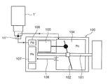
- the swash plate type variable displacement compressor 100 includes a rotary shaft 101 that is driven to rotate by an in-vehicle engine, a swash plate 102 attached to the rotary shaft 101, a crank chamber 104 in which the swash plate 102 is disposed, and the swash plate.
- the piston 105 reciprocated by the piston 102, the discharge chamber 106 for discharging the refrigerant compressed by the piston 105, the suction chamber 107 for sucking the refrigerant, and the pressure Pc of the crank chamber 104 for releasing the pressure Pc to the suction chamber 107
- An in-flight escape passage (fixed orifice) 108 and the like are provided.
- the control valve 1 ′ used in the variable displacement compressor is supplied with the discharge pressure Pd from the discharge chamber 106 of the compressor 100 and adjusts the discharge pressure Pd according to the suction pressure Ps of the compressor 100.
- the pressure Pc of the crank chamber 104 is controlled.
- the valve chamber has a valve chamber provided with a valve port and a Ps introduction port communicating with the suction chamber 107 of the compressor 100.
- a valve main body provided with a Pd introduction port communicating with the discharge chamber 106 of the compressor 100 upstream from the port and with a Pc outlet opening communicating with the crank chamber 104 of the compressor 100 downstream of the valve port.
- An electromagnetic actuator having a valve body (valve rod) for opening and closing the valve opening, a plunger for moving the valve body in the valve opening / closing direction (vertical direction), and the compressor 10
- a pressure sensing chamber into which the suction pressure Ps is introduced through the Ps introduction port, and a pressure sensitive responsive member that urges the valve body in the valve opening / closing direction in accordance with the pressure in the pressure sensing chamber.
- the valve body and the valve port constitute a valve portion denoted by reference numeral 11 'in FIG. 10 (see, for example, Patent Document 1 below).
- the solenoid portion including the coil, the stator, and the attractor of the electromagnetic actuator when the solenoid portion including the coil, the stator, and the attractor of the electromagnetic actuator is energized, the plunger is attracted to the attractor, and the valve body is closed accordingly. The urging force of the spring is moved in the valve closing direction so as to follow the plunger.
- the suction pressure Ps introduced from the compressor 100 through the Ps introduction port enters the pressure sensitive chamber through a gap formed between the plunger and the guide pipe disposed on the outer periphery thereof.
- the pressure-responsive member for example, a bellows device
- suction pressure Ps contraction pressure
- the displacement biasing force
- the valve body portion of the valve body moves up and down with respect to the valve port
- the valve opening degree of the valve portion 11 ′ is adjusted. That is, the valve opening degree is determined by the attraction force of the plunger by the solenoid part, the urging force (extension / contraction force) due to the expansion / contraction displacement of the pressure-sensitive response member, and the urging force by the plunger spring (valve opening spring) and the valve closing spring.
- the pressure Pc in the crank chamber 104 (hereinafter sometimes referred to as the crank chamber pressure Pc or simply the pressure Pc) is controlled in accordance with the valve opening.
- variable capacity compressor for example, the time required for the discharge capacity to be increased at the time of starting the compressor is shortened, and the reduction in the operation efficiency of the compressor at the time of normal control is suppressed or reduced.
- an improved swash plate type variable displacement compressor as shown in FIGS. 11A and 11B has been proposed.
- a valve body (valve rod) in a control valve used therefor is composed of a main valve body and a sub-valve body, and an in-valve escape passage 16 'is formed in the main valve body.
- the control valve 2 ′ basically has a valve chamber provided with a valve port and a Ps inlet / outlet communicating with the suction chamber 107 of the compressor 200, upstream of the valve port.
- a valve main body provided with a Pd introduction port communicating with the discharge chamber 106 of the compressor 200 and provided with a Pc inlet / outlet communicating with the crank chamber 104 of the compressor 200 on the downstream side of the valve port;
- a suction valve Ps is introduced from the compressor 200 through the Ps inlet / outlet.
- the main valve body for opening and closing the valve the electromagnetic actuator having a plunger for moving the main valve body in the valve opening / closing direction, and the compressor 200
- the pressure sensitive chamber and the pressure in the pressure sensitive chamber A pressure-sensitive response member that urges the main valve body in the valve opening / closing direction, and for releasing the pressure Pc of the crank chamber 104 to the suction chamber 107 of the compressor 200 via the Ps inlet / outlet.
- An in-valve relief passage 16 ' is provided in the main valve body, and a sub-valve body for opening and closing the in-valve escape passage 16' is provided, and the plunger is moved upward from the lowest position by the suction force of the electromagnetic actuator.
- the sub-valve element moves together with the plunger while moving the valve relief passage 16 'upward, and the main valve body follows the sub-valve body.
- the valve port is closed by the main valve body after being moved upward, when the plunger is further moved upward, the sub-valve body opens the in-valve escape passage 16 '.
- the main valve body and the valve port constitute a main valve portion indicated by reference numeral 11 ', and the auxiliary valve body and the valve relief passage are indicated by reference numeral 12'.
- control valve 2 ′ having such a configuration, during normal control (Pd ⁇ Pc control), when a solenoid portion including a coil, a stator, and an attractor of an electromagnetic actuator is energized, the plunger is attracted to the attractor. Accordingly, the sub-valve element moves upward in unison with the plunger, and the main valve element is moved in the valve-closing direction by the urging force of the valve-closing spring following this movement.
- the suction pressure Ps introduced from the compressor 200 through the Ps inlet / outlet is introduced from the inlet / outlet chamber into the pressure sensitive chamber through the side hole of the plunger, and the pressure sensitive reaction member (for example, the bellows device) is pressure sensitive.
- Expansion and contraction displacement (contraction when suction pressure Ps is high and expansion when suction pressure Ps is low) according to the pressure in the chamber (suction pressure Ps), and the displacement (biasing force) is transmitted to the main valve body.
- the main valve body portion of the main valve body is raised and lowered to adjust the valve opening degree of the main valve portion 11 ′.
- the valve opening includes the plunger suction force by the solenoid part, the biasing force (extension force) due to the expansion / contraction displacement of the pressure sensitive member, the biasing force due to the plunger spring (valve opening spring) and the valve closing spring, and the main valve It is determined by the force in the valve opening direction and the force in the valve closing direction acting on the body, and the pressure Pc in the crank chamber 104 is controlled according to the valve opening degree.
- the main valve body is always urged upward by the urging force of the valve closing spring, and the sub valve body is always urged downward by the urging force of the valve opening spring. Is closed, the in-valve escape passage 16 ′ is blocked in the main valve body, and the crank chamber pressure Pc is not released to the suction chamber 107 through the in-valve escape passage 16 ′.
- the passage diameter (hole diameter) of the escape passage in the valve is increased to secure the flow rate.
- the outer diameter of the subvalve element that opens and closes the escape passage in the valve increases, the inner diameter of the cylindrical plunger extrapolated to the subvalve element increases, and the upper end (surface) of the plunger that faces the suction element.
- the area (magnetic path area) of the electromagnetic actuator is inevitably reduced, and the attractive force of the electromagnetic actuator is reduced. Therefore, there is a problem that it is difficult to reduce the size (particularly, the coil portion of the electromagnetic actuator).
- the present invention has been made in view of the above circumstances, and the object of the present invention is to ensure the size of the sub-valve body portion of the sub-valve body that opens and closes the escape passage in the valve with a simple configuration, and starts up.
- An object of the present invention is to provide a variable displacement compressor control valve that can improve performance and reduce size.
- a control valve for a variable displacement compressor basically has a valve chamber provided with a valve port and a Ps inlet / outlet communicating with a suction chamber of the compressor, A valve body provided with a Pd introduction port communicating with the discharge chamber of the compressor upstream from the valve port, and provided with a Pc inlet / outlet communicating with the crank chamber of the compressor downstream from the valve port; A main valve body for opening and closing the valve port, an electromagnetic actuator having a plunger and an attractor for moving the main valve body in the valve port opening and closing direction, and a suction pressure Ps from the compressor is the Ps inlet / outlet port A pressure sensing chamber introduced through the pressure sensing chamber, and a pressure sensing responsive member that urges the main valve body in the valve opening / closing direction according to the pressure in the pressure sensing chamber, and the pressure Pc of the crank chamber is In-valve escape to escape to the compressor suction chamber via the Ps inlet / outlet A passage is provided in the main valve chamber
- the plunger has a cylindrical shape, and the auxiliary valve body is inserted and fixed to the plunger.
- auxiliary valve body is press-fitted into the plunger and fixed.
- sub-valve element and the plunger are configured and fixed as separate members.
- auxiliary valve body and the plunger are integrally formed.
- the sub-valve element is made of a magnetic material that is the same or different from the plunger, or is made of a non-magnetic material.
- the projected area of the lower surface of the suction element with respect to the horizontal plane is the same as the projected area of the auxiliary valve body and / or the upper surface of the plunger with respect to the horizontal plane.
- the plunger is fixed to the plunger so that the auxiliary valve body always moves together, so that a locking mechanism between the plunger and the auxiliary valve body is unnecessary. Therefore, the outer diameter of the sub-valve part of the sub-valve element that opens and closes the valve relief passage can be increased, and the size can be reduced while improving the startability.
- the projected area (area corresponding to the magnetic path area) of the lower surface of the attractor (opposing surface on the plunger side) with respect to the horizontal plane and the horizontal surface of the upper surface (opposing surface on the attractor side) of the subvalve element and / or the plunger Since the projected area (area corresponding to the magnetic path area) is the same, it is possible to secure the attractive force of the electromagnetic actuator without increasing the physique. It is possible to reduce the size of the coil portion.
- FIG. 4B is a top view of FIG. 4B.
- FIG. 4B is a bottom view of FIG. 4B.
- FIG. 4B is a cross-sectional view taken along the line U-U in FIG. 4B.
- 4D is a cross-sectional view showing a modified example of the plunger and the auxiliary valve body shown in FIGS. 4A to 4E, and is a view similar to FIG. 4E.
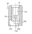
- the longitudinal cross-sectional view which shows the main valve of the 2nd Embodiment of the control valve for variable displacement type compressors which concerns on this invention Closed and a subvalve: An open state (at the time of compressor starting).
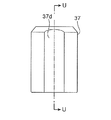
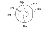
- the front view which shows the plunger with a subvalve body used for 2nd Embodiment of the control valve for variable displacement compressors which concerns on this invention.
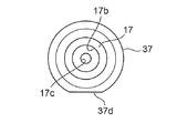
- the top view which shows the plunger with a subvalve body used for 2nd Embodiment of the control valve for variable displacement type compressors which concerns on this invention.
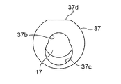
- the bottom view which shows the plunger with a subvalve body used for 2nd Embodiment of the control valve for variable displacement compressors which concerns on this invention.
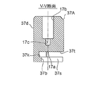
- FIG. 9D is a cross-sectional view taken along the line VV in FIG. 9D.
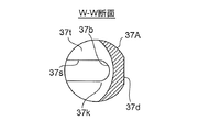
- FIG. 9B is a cross-sectional view taken along the line WW in FIG. 9A.
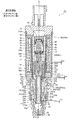
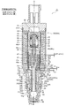
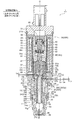
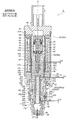
- FIG. 1 is a state in which a main valve is open and a sub valve is closed (normal control). 2), FIG. 2 shows the main valve: closed, sub valve: closed (when the compressor starts up), and FIG. 3 shows the main valve: closed, sub valve: open (when the compressor is started).
- the gap formed between the members, the separation distance between the members, etc. are larger than the dimensions of each constituent member for easy understanding of the invention and for convenience of drawing. Or it may be drawn small.
- the control valve 1 of the illustrated embodiment includes a valve body 20 provided with a valve port 22, a valve body 10 having a main valve body 15 for opening and closing the valve port 22, and the valve body 10 (main valve body 15). Is provided with an electromagnetic actuator 30 for moving the valve opening / closing direction (vertical direction) and a bellows device 40 as a pressure-sensitive response member.
- the electromagnetic actuator 30 includes a bobbin 38, a coil 32 for energizing energization provided on the bobbin 38, a stator 33 and an attractor 34 disposed on the inner peripheral side of the coil 32, and lower ends of the stator 33 and the attractor 34.
- a guide pipe 35 whose upper end is joined to the outer periphery (step part) by welding, and a bottomed cylindrical plunger disposed below the suction element 34 and slidably in the vertical direction on the inner peripheral side of the guide pipe 35 37, a cylindrical housing 60 extrapolated to the coil 32, a connector head 31 attached to the upper side of the housing 60 via an attachment plate 39, and a lower end portion of the housing 60 and a lower end portion of the guide pipe 35 And a holder 29 for fixing them to the upper part of the valve body 20.
- a cylindrical suction element 34 in which an insertion hole 34a having a diameter smaller than the inner diameter of the stator 33 is formed in the center (along the axis O) is formed integrally with the lower inner periphery of the cylindrical stator 33.
- an O-ring 31 ⁇ / b> A as a sealing material is mounted on the outer periphery of the connector head 31 (annular mounting groove formed therein).
- solenoid part 30A the part which consists of the coil 32, the stator 33, the attractor 34, etc. except the plunger 37 among the electromagnetic actuators 30 is called solenoid part 30A.
- a short cylindrical stator 65 is fixed to the upper portion of the stator 33 by press fitting or the like, and between the stator 65 and the suction element 34 on the inner peripheral side of the stator 33, the compressor 100.
- a pressure-sensitive chamber 45 into which the suction pressure Ps is introduced is formed.
- a bellows device 40 including a compression coil spring 44 is disposed.
- a stepped rod-like push rod 46 as a thrust transmission member is disposed along the axis O below the bellows device 40.
- the push rod 46 has an upper small-diameter portion 46d, an intermediate body portion (sliding portion) 46c, and a lower small-diameter portion 46b from the upper side, and an upper small-diameter portion (secondary portion) of the push rod 46 in the recess of the lower stopper 43. 46d is inserted and supported, and an intermediate body portion 46c of the push rod 46 is slidably inserted in the insertion hole 34a of the suction element 34.
- the lower small diameter portion 46b of the push rod 46 is inserted into a concave hole 17b of the sub-valve body 17 having a concave cross section which will be described later, and a lower end portion 46a thereof is an insertion hole formed at the center of the bottom portion of the concave hole 17b. 17c.
- a sub-valve element 17 having a concave cross section having a vertically long concave hole 17b having substantially the same diameter as the insertion hole 34a of the suction element 34 is fixed by insertion or the like.
- the upper end of the sub-valve body 17 is aligned with the upper end of the plunger 37 (in other words, the upper end is positioned on the inner periphery of the upper end of the plunger 37), and the lower end of the sub-valve body 17 is spaced from the bottom of the plunger 37.
- the hook-like locking portion 15k of the main valve body 15 is fitted in the plunger 37 in a state where there is a gap in which the main valve body 15 can be moved up and down slightly).
- a concave insertion hole 17c into which the lower end portion 46a of the push rod 46 (the lower small diameter portion 46b) is inserted is formed in the center of the bottom portion of the concave hole 17b of the sub valve body 17.
- a stepped portion (downward annular terrace surface) formed between the upper small-diameter portion 46d of the push rod 46 and the intermediate body portion 46c and the bottom of the concave hole 17b of the subvalve body 17 (around the fitting insertion hole 17c)
- the auxiliary valve body 17 and the plunger 37 are urged downward (in the valve opening direction) so as to be externally inserted into the lower small diameter portion 46b of the push rod 46.
- a plunger spring (valve opening spring) 47 formed of a cylindrical compression coil spring is retracted, and the sub-valve body 17 and the plunger 37 are in a state where the sub-valve body 17 is biased downward by the plunger spring 47. Move up and down together.
- a center hole 37b having a smaller diameter than the inner diameter of the plunger 37 is formed at the center (on the axis O) at the bottom of the plunger 37, and slightly from the center.
- An insertion hole 37c having substantially the same diameter as the inner diameter of the plunger 37 (in other words, larger in diameter than the central hole 37b) is formed at an eccentric position so as to partially overlap the central hole 37b.
- the insertion hole 37 c is drilled to a depth (depth in the vertical direction) communicating with the internal space of the plunger 37.
- the hole diameter of the insertion hole 37c (the inner diameter of the plunger 37, the outer diameter of the sub-valve element 17) is slightly larger than the flange-shaped locking portion 15k of the main valve element 15 described later, and the center hole 37b
- the hole diameter is slightly larger than the upper small diameter portion 15 f of the main valve body 15 and slightly smaller than the hook-shaped locking portion 15 k, and the outer peripheral portion of the central hole 37 b on the bottom upper surface of the plunger 37 is An inner hook-shaped hooking portion 37k for hooking the hook-shaped locking portion 15k is used.
- the distance (in the vertical direction) between the bottom portion (upper surface) of the plunger 37 and the lower end portion (flat surface) of the sub-valve body 17 is slightly larger than the height of the hook-shaped locking portion 15k of the main valve body 15.
- the thickness (vertical height) of the bottom portion of the plunger 37 is slightly larger than the height of the upper small diameter portion 15 f of the main valve body 15, and the main valve body 15 can move up and down with respect to the plunger 37. (Details will be described later).
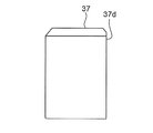
- a D-cut surface 37 d is formed at a predetermined position on the outer periphery of the plunger 37, and a gap 36 is formed between the outer periphery of the plunger 37 (the D-cut surface 37 d) and the guide pipe 35.
- the D-cut surface 37d one or a plurality of vertical grooves may be formed, and the gap 36 may be formed between the outer periphery of the plunger 37 and the guide pipe 35.
- the valve body 10 is composed of a stepped shaft-shaped main valve body 15 arranged in the vertical direction (along the axis O direction) and the sub-valve body 17 described above.
- the main valve body 15 disposed on the lower side is made of a non-magnetic material, and in order from the bottom, the main valve body portion 15a, the intermediate small diameter portion 15d, the relatively long fitting insertion portion 15e, the upper small diameter portion 15f, and the bowl shape
- the locking portion 15k is formed, and a through relief hole 16A constituting a part of the in-valve escape passage 16 is provided in the center of the inside so as to penetrate in the vertical direction.
- the upper end portion (inverted truncated cone surface portion) of the through escape hole 16A serves as a sub-valve seat portion 23 to which the lower end portion (sub-valve body portion) 17a of the sub-valve body 17 contacts and separates.
- the upper small-diameter portion 15f of the main valve body 15 is loosely fitted in the central hole 37b, and the hook-shaped locking portion 15k of the main valve body 15 has a larger diameter than the central hole 37b (and a smaller diameter than the inner diameter of the plunger 37).
- the hook-like locking part 15 k is hooked by the inner hook-like hooking part 37 k formed by the outer peripheral part of the central hole 37 b and comes off. It is designed to be locked and locked.
- the outer diameter of the hook-shaped locking portion 15k is made larger, and the lower end portion (flat surface) thereof is brought into contact with and separated from the auxiliary valve seat portion 23 which is the upper end edge portion of the through escape hole 16A to open and close the in-valve escape passage 16 It is set as the subvalve body part 17a to do.
- the auxiliary valve seat part 23 is comprised by the auxiliary valve seat part 23 and the auxiliary valve body part 17a.
- the sub-valve element 17 may be made of the same magnetic material as that of the plunger 37 made of a magnetic material, or may be made of a magnetic material made of a different material from the plunger 37. In other words, if it is made of a magnetic material having a different magnetic force, the characteristics of the attractive force of the electromagnetic actuator 30 can be appropriately adjusted. Moreover, you may comprise this subvalve body 17 with a nonmagnetic material.
- the sub-valve element 17 is constituted by one member (one part), but may be constituted by assembling a plurality of members.
- the sub-valve body 17 is fixed to the plunger 37 (a predetermined position inside the plunger 37) by press-fitting or the like, 20 is inserted into the insertion hole 37c of the plunger 37 from below, and the main valve body 15 is inserted into the plunger 37.
- the upper small-diameter portion 15f of the main valve body 15 is inserted into a central hole 37b provided in the center of the bottom portion of the plunger 37, and the main valve body 15 (the hook-shaped locking portion thereof) is placed below the sub-valve body 17. 15k) may be arranged.
- valve main body 20 has a two-part configuration of a main body member 20A provided with a concave hole 20C for fitting in the upper center and a support member 20B that is inserted and fixed into the concave hole 20C by press fitting or the like. Yes.
- the support member 20B is made of a relatively hard material such as stainless steel (SUS), for example, and is a convex for defining the lowest position of the plunger 37 on the upper side of the insertion portion 24 to be inserted into the concave hole 20C.
- 24A-shaped stopper part 24A is protrudingly provided.
- the fitting insertion portion 24 is formed with a step, and a lower small diameter portion 24b whose vertical length is longer than the upper large diameter portion 24a is provided below the upper large diameter portion 24a.
- a flange-shaped contact portion 24c that is brought into contact with a step portion (step surface) between the recessed hole 20C of the main body member 20A and the accommodation hole 18 and projects outward. It has been.
- a guide hole 19 into which the insertion portion 15e of the main valve body 15 is slidably inserted so as to penetrate in the vertical direction is formed in the center portion of the support member 20B.
- the valve port 22 (valve seat portion) is opened and closed by the main valve body portion 15a of the main valve body 15.
- the main valve part 11 is comprised by the main valve body part 15a and the valve port 22.
- FIG. As described above, since the support member 20B is made of a high-hardness material such as stainless steel, its specific gravity is also high.
- the main body member 20A is made of a material having a relatively low specific gravity (ie, a material having a relatively low hardness) compared to, for example, aluminum, brass, or stainless steel such as resin, and the support member 20B is inserted into the recessed hole 20C of the main body member 20A.
- an inlet / outlet chamber 28 for the suction pressure Ps of the compressor 100 is formed on the outer periphery of the stopper portion 24A, and a plurality of inlet / outlet chambers 28 are provided on the outer peripheral side of the inlet / outlet chamber 28. Ps inlet / outlet 27 is formed.
- the suction pressure Ps introduced into the inlet / outlet chamber 28 from the Ps inlet / outlet 27 is a gap 36 formed between the outer periphery of the plunger 37 and the guide pipe 35 (in this example, a gap formed by the D-cut surface 37d). Etc., and is introduced into the pressure sensitive chamber 45.
- the concave hole 20C in the main body member 20A is also formed with a step, and the upper large-diameter hole 20Ca into which the upper large-diameter portion 24a of the support member 20B is inserted and the lower small-diameter hole into which the lower small-diameter portion 24b is inserted.
- 20Cb, and the outer periphery of the upper large-diameter portion 24a and the inner periphery of the upper large-diameter hole 20Ca abut (in other words, the upper large-diameter portion 24a is fitted (inscribed) into the upper large-diameter hole 20Ca.
- the support member 20B is inserted and fixed in the recessed hole 20C of the main body member 20A in a posture having a slight gap between the outer periphery of the lower small diameter portion 24b and the inner periphery of the lower small diameter hole 20Cb.
- a stepped accommodation hole 18 for accommodating the main valve body portion 15a of the main valve body 15 is continuously provided at the bottom center of the lower small diameter hole 20Cb.
- a conical compression coil spring is used between the stepped portion provided in the inner periphery of the receiving hole 18 and the stepped portion (step surface) 15g provided in the lower outer periphery of the main valve body portion 15a of the main valve body 15.
- the valve closing spring 50 is contracted, and the urging force of the valve closing spring 50 presses the main valve body 15 (the stepped portion between the fitting insertion portion 15e and the upper small diameter portion 15f) against the plunger 37 (the bottom thereof).
- the inside of the accommodation hole 18 (the lower part from the valve port 22 of the support member 20B) serves as a valve chamber 21, and communicates with the lower small-diameter hole 20Cb of the concave hole 20C to the discharge chamber 106 of the compressor 100.
- a plurality of Pd introduction ports 25 are opened, and a ring-shaped filter member 25A is externally provided on the outer periphery of the Pd introduction port 25.
- the lower small diameter portion 24b of the fitting insertion portion 24 communicates with the Pd introduction port 25.
- a plurality of lateral holes 25s are provided.
- a lid-like member 48 functioning as a filter is fixed to the lower end portion of the main body member 20A by engagement, press-fitting or the like, and the upper side of the lid-like member 48 and the lower side of the housing hole 18 is the compressor 100.
- a Pc entrance / exit chamber (entrance / exit) 26 communicates with the crank chamber 104.
- This Pc entrance / exit chamber (entrance / exit) 26 is composed of a clearance between the valve chamber 21 ⁇ the valve port 22 and the main valve body 15a ⁇ a clearance between the lower portion of the guide hole 19 and the intermediate small diameter portion 15d ⁇ a lower small diameter portion.
- the horizontal hole 25s of 24b is communicated with the Pd inlet 25 through a gap between the lower small diameter portion 24b and the lower small diameter hole 20Cb.
- the pressure Pc of the crank chamber 104 is input to Ps through the through relief hole 16A formed in the main valve body 15, the central hole 37b and the insertion hole 37c provided in the plunger 37, the inlet / outlet chamber 28, and the like.
- An in-valve escape passage 16 is formed to escape to the suction chamber 107 of the compressor 100 via the outlet 27, and the sub-valve body 17 is connected to the sub-valve seat portion 23 which is the upper edge of the through-hole 16 A of the main valve body 15. When the sub-valve body portion 17a contacts and separates, the in-valve escape passage 16 is opened and closed.
- the plunger 37, the main valve body 15, and the sub-valve body 17 are in the lowest lowered position (the lowermost end surface of the plunger 37 is the stopper portion. 24A, the main valve part 11 is fully open, and the sub-valve part 12 is fully closed).
- the second lift amount Lp (the lift amount from the lowest position of the plunger 37 to the highest position) is the first lift amount Lv + the predetermined amount La.
- the lift amount of the plunger 37 (and the subvalve body 17) is set to be a little greater than the first lift amount Lv at the maximum, and when the compressor is started (Pc ⁇ Ps control) In this case, the lift amount of the plunger 37 (and the auxiliary valve body 17) is set to the second lift amount Lp.
- the device 40 (inside the vacuum pressure) expands and contracts (contracts when the suction pressure Ps is high and expands when the suction pressure Ps is low) according to the pressure of the pressure sensing chamber 45 (suction pressure Ps). 17 is transmitted to the main valve body 15, thereby adjusting the valve opening (separation distance between the valve port 22 and the main valve body 15 a), and according to the valve opening, The pressure Pc is adjusted. Accordingly, the inclination angle of the swash plate 102 of the compressor 100 and the stroke of the piston 105 are adjusted, and the discharge capacity is increased or decreased.
- the main valve body 15 is always urged upward by the urging force of the valve closing spring 50, and the sub valve body 17 is always urged downward by the urging force of the valve opening spring 47.
- the valve body portion 17 a is pressed against the sub valve seat portion 23 (the sub valve portion 12 is closed), and the valve relief passage 16 is blocked in the main valve body 15. Therefore, the crank chamber pressure Pc is not released to the suction chamber 107 through the in-valve escape passage 16.
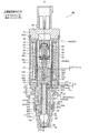
- the solenoid portion 30A is energized and energized, and the plunger 37 and the sub-valve body 17 are drawn together (upward) to the attractor 34, and the main valve body 15 follows this upward movement. Is moved upward and the valve port 22 is closed by the main valve body portion 15a of the main valve body 15, and then the plunger 37 and the sub-valve body 17 are further moved upward, whereby the sub-valve body 17 Is opened in the valve relief passage 16, and the pressure Pc in the crank chamber 104 is released to the suction chamber 107 through the two passages of the in-machine escape passage 108 and the valve relief passage 16.
- the main valve body 15 is moved by the biasing force of the valve-closing spring 50.
- the valve port 22 is closed by the main valve body portion 15a of the main valve body 15 (see FIG. 2), the plunger 37 and the sub-valve element 17 are further moved upward by the predetermined amount La from the closed state of the main valve portion 11 (the state shown in FIG. 3).
- the inner hook-shaped hooking portion 37k of the plunger 37 becomes the hook-shaped locking portion 15k of the main valve body 15.
- the sub-valve body portion 17a of the sub-valve body 17 is lifted by a predetermined amount La from the sub-valve seat portion 23, and thereby the in-valve escape passage. 16 is opened.
- the auxiliary valve body 17 is inserted and fixed to the plunger 37 with the upper end portion of the auxiliary valve body 17 aligned with the upper end portion of the plunger 37.
- the attractive force characteristics of the electromagnetic actuator 30 can be adjusted.
- the plunger 37 and the sub-valve body 17 are fixed to the plunger 37 so that the sub-valve element 17 always moves together. Since the outer diameter of the sub-valve part 17a of the sub-valve element 17 that opens and closes the in-valve escape passage 16 can be increased, it is possible to reduce the size while improving the startability. Become.
- the surface obtained by combining the upper surface of the sub-valve body 17 and the upper surface of the plunger 37) (projecting surface on the side of the attractor 34) with respect to the horizontal plane (area corresponding to the magnetic path area) is substantially the same. Therefore, since the attractive force of the electromagnetic actuator 30 can be ensured without increasing the physique, it is possible to further reduce the size (particularly, the coil 32 portion of the electromagnetic actuator 30). Become.
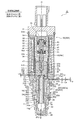
- Second Embodiment 6 to 8 are longitudinal sectional views showing a second embodiment of the control valve for a variable displacement compressor according to the present invention.
- FIG. 6 shows a state where the main valve is open and the subvalve is closed (normal control). 7)
- FIG. 7 shows the main valve: closed, the subvalve: closed (when the compressor starts up)
- FIG. 8 shows the main valve: closed, the subvalve: open (when the compressor is started).
- the control valve 2 of the second embodiment is basically different from the control valve 1 of the first embodiment only in the configuration of the plunger 37 and the auxiliary valve body 17. Therefore, components having the same functions as those in the first embodiment are denoted by the same reference numerals and detailed description thereof is omitted, and only the differences described above will be described in detail below.
- the plunger 37 and the sub-valve element 17 are constituted by separate members (separate parts) and fixed, but in the control valve 2 of the present embodiment, the plunger 37 and the sub-valve element are fixed. 17 is integrally formed (hereinafter, collectively referred to as a plunger 37A with a secondary valve body). That is, here, the auxiliary valve body 17 is made of the same magnetic material as that of the plunger 37.
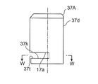
- a central hole 37b similar to that of the first embodiment is formed in the lower part of the plunger 37A with a sub-valve element, and the central hole 37b
- a slit 37s having a width substantially the same as the hole diameter of the central hole 37b is formed extending linearly from the outer periphery to the outer periphery, and overlaps the central hole 37b and the slit 37s above the central hole 37b and the slit 37s.
- a substantially semicircular cut 37t is formed (toward the lateral direction) in plan view.
- the height (in the vertical direction) of the cut 37t is slightly larger than the height of the hook-shaped locking portion 15k of the main valve body 15, and the height (in the vertical direction) of the slit 37s and the center hole 37b is as follows.
- the main valve body 15 is slightly smaller than the height of the upper small-diameter portion 15 f of the main valve body 15, and the main valve body 15 can move up and down with respect to the plunger 37.
- the width (in the lateral direction) of the slit 37s is slightly larger than the outer diameter of the upper small diameter portion 15f of the main valve body 15 in consideration of assemblability and the like, and the hook-like engagement of the main valve body 15 is performed. It is made smaller than the outer diameter of the part 15k.
- valve body 10 main valve body 15
- sub-valve-equipped plunger 37A When the valve body 10 (main valve body 15) and the sub-valve-equipped plunger 37A are assembled, for example, the hook-shaped locking portion 15k and the upper portion of the main valve body 15 previously assembled to the valve body 20 (the guide hole 19 thereof).
- the main valve body 15 is laterally moved with respect to the plunger 37A with a sub-valve so that the small diameter portion 15f is inserted into the notch 37t and the slit 37s of the plunger 37A with the sub-valve, respectively. What is necessary is just to insert the upper small diameter part 15f in the center hole 37b provided in the lower center.
- control valve 2 of the second embodiment configured as described above, the same operational effects as those of the control valve 1 of the first embodiment can be obtained, and the plunger 37 and the sub-valve body 17 are formed as one component (integral molding). Product), the number of parts and product cost can be further reduced.
- Control valve for variable displacement compressor (first embodiment) 2 Control valve for variable displacement compressor (second embodiment) DESCRIPTION OF SYMBOLS 10 Valve body 11 Main valve part 12 Sub valve part 15 Main valve body 15a Main valve body part 15k Saddle-shaped latching
Landscapes
- Engineering & Computer Science (AREA)
- General Engineering & Computer Science (AREA)
- Mechanical Engineering (AREA)
- Magnetically Actuated Valves (AREA)
- Compressors, Vaccum Pumps And Other Relevant Systems (AREA)
- Multiple-Way Valves (AREA)
- Physics & Mathematics (AREA)
- Thermal Sciences (AREA)
Priority Applications (5)
| Application Number | Priority Date | Filing Date | Title |
|---|---|---|---|
| US16/309,036 US20190316697A1 (en) | 2016-06-28 | 2017-04-20 | Variable-capacity compressor control valve [as amended] |
| MX2018014960A MX2018014960A (es) | 2016-06-28 | 2017-04-20 | Valvula de control para compresor de capacidad variable. |
| EP17819616.8A EP3477106A4 (en) | 2016-06-28 | 2017-04-20 | CONTROL VALVE FOR A VARIABLE CAPACITY COMPRESSOR |
| KR1020187035766A KR20190003769A (ko) | 2016-06-28 | 2017-04-20 | 가변용량형 압축기용 제어 밸브 |
| CN201780040274.5A CN109416035B (zh) | 2016-06-28 | 2017-04-20 | 可变容量型压缩机用控制阀 |
Applications Claiming Priority (2)
| Application Number | Priority Date | Filing Date | Title |
|---|---|---|---|
| JP2016127920A JP6600604B2 (ja) | 2016-06-28 | 2016-06-28 | 可変容量型圧縮機用制御弁 |
| JP2016-127920 | 2016-06-28 |
Publications (1)
| Publication Number | Publication Date |
|---|---|
| WO2018003249A1 true WO2018003249A1 (ja) | 2018-01-04 |
Family
ID=60787134
Family Applications (1)
| Application Number | Title | Priority Date | Filing Date |
|---|---|---|---|
| PCT/JP2017/015835 Ceased WO2018003249A1 (ja) | 2016-06-28 | 2017-04-20 | 可変容量型圧縮機用制御弁 |
Country Status (7)
| Country | Link |
|---|---|
| US (1) | US20190316697A1 (enExample) |
| EP (1) | EP3477106A4 (enExample) |
| JP (1) | JP6600604B2 (enExample) |
| KR (1) | KR20190003769A (enExample) |
| CN (1) | CN109416035B (enExample) |
| MX (1) | MX2018014960A (enExample) |
| WO (1) | WO2018003249A1 (enExample) |
Families Citing this family (3)
| Publication number | Priority date | Publication date | Assignee | Title |
|---|---|---|---|---|
| JP6757074B2 (ja) * | 2018-02-08 | 2020-09-16 | 株式会社不二工機 | 可変容量型圧縮機用制御弁 |
| JP2020067002A (ja) * | 2018-10-22 | 2020-04-30 | 株式会社不二工機 | 可変容量型圧縮機用制御弁 |
| USD913337S1 (en) * | 2019-01-14 | 2021-03-16 | Henry C. Chu | Compressor internal control valve |
Citations (1)
| Publication number | Priority date | Publication date | Assignee | Title |
|---|---|---|---|---|
| JP2013130126A (ja) * | 2011-12-21 | 2013-07-04 | Fuji Koki Corp | 可変容量型圧縮機用制御弁 |
Family Cites Families (6)
| Publication number | Priority date | Publication date | Assignee | Title |
|---|---|---|---|---|
| JP4333042B2 (ja) * | 2001-02-20 | 2009-09-16 | 株式会社豊田自動織機 | 容量可変型圧縮機の制御弁 |
| KR100858604B1 (ko) * | 2001-11-30 | 2008-09-17 | 가부시기가이샤 후지고오키 | 가변용량형 압축기용 제어밸브 |
| JP4331667B2 (ja) * | 2004-10-22 | 2009-09-16 | 株式会社テージーケー | 可変容量圧縮機用制御弁 |
| JP4504243B2 (ja) * | 2005-04-12 | 2010-07-14 | 株式会社不二工機 | 可変容量型圧縮機用制御弁 |
| JP5878703B2 (ja) * | 2010-09-06 | 2016-03-08 | 株式会社不二工機 | 可変容量型圧縮機用制御弁 |
| JP6340661B2 (ja) * | 2014-02-27 | 2018-06-13 | 株式会社テージーケー | 可変容量圧縮機用制御弁 |
-
2016
- 2016-06-28 JP JP2016127920A patent/JP6600604B2/ja not_active Expired - Fee Related
-
2017
- 2017-04-20 US US16/309,036 patent/US20190316697A1/en not_active Abandoned
- 2017-04-20 EP EP17819616.8A patent/EP3477106A4/en not_active Withdrawn
- 2017-04-20 CN CN201780040274.5A patent/CN109416035B/zh not_active Expired - Fee Related
- 2017-04-20 WO PCT/JP2017/015835 patent/WO2018003249A1/ja not_active Ceased
- 2017-04-20 KR KR1020187035766A patent/KR20190003769A/ko not_active Ceased
- 2017-04-20 MX MX2018014960A patent/MX2018014960A/es unknown
Patent Citations (1)
| Publication number | Priority date | Publication date | Assignee | Title |
|---|---|---|---|---|
| JP2013130126A (ja) * | 2011-12-21 | 2013-07-04 | Fuji Koki Corp | 可変容量型圧縮機用制御弁 |
Non-Patent Citations (1)
| Title |
|---|
| See also references of EP3477106A4 * |
Also Published As
| Publication number | Publication date |
|---|---|
| JP2018003882A (ja) | 2018-01-11 |
| JP6600604B2 (ja) | 2019-10-30 |
| EP3477106A1 (en) | 2019-05-01 |
| MX2018014960A (es) | 2019-04-25 |
| EP3477106A4 (en) | 2020-02-26 |
| CN109416035A (zh) | 2019-03-01 |
| US20190316697A1 (en) | 2019-10-17 |
| KR20190003769A (ko) | 2019-01-09 |
| CN109416035B (zh) | 2020-03-13 |
Similar Documents
| Publication | Publication Date | Title |
|---|---|---|
| JP6383720B2 (ja) | 可変容量型圧縮機用制御弁 | |
| JP6626789B2 (ja) | 可変容量型圧縮機用制御弁 | |
| JP7658832B2 (ja) | 可変容量型圧縮機用制御弁 | |
| JP6395696B2 (ja) | 可変容量型圧縮機用制御弁 | |
| CN109715943B (zh) | 可变容量型压缩机用控制阀 | |
| WO2018003253A1 (ja) | 可変容量型圧縮機用制御弁 | |
| JP2017110544A (ja) | 可変容量型圧縮機用制御弁 | |
| JP6355617B2 (ja) | 可変容量型圧縮機用制御弁 | |
| WO2018003252A1 (ja) | 可変容量型圧縮機用制御弁 | |
| JP6600604B2 (ja) | 可変容量型圧縮機用制御弁 | |
| JP6600603B2 (ja) | 可変容量型圧縮機用制御弁及びその組立方法 | |
| JP5269391B2 (ja) | 可変容量型圧縮機用制御弁 | |
| WO2018003251A1 (ja) | 可変容量型圧縮機用制御弁 |
Legal Events
| Date | Code | Title | Description |
|---|---|---|---|
| 121 | Ep: the epo has been informed by wipo that ep was designated in this application |
Ref document number: 17819616 Country of ref document: EP Kind code of ref document: A1 |
|
| ENP | Entry into the national phase |
Ref document number: 20187035766 Country of ref document: KR Kind code of ref document: A |
|
| NENP | Non-entry into the national phase |
Ref country code: DE |
|
| ENP | Entry into the national phase |
Ref document number: 2017819616 Country of ref document: EP Effective date: 20190128 |