WO2017221990A1 - Functional layer including layered double hydroxide, and composite material - Google Patents
Functional layer including layered double hydroxide, and composite material Download PDFInfo
- Publication number
- WO2017221990A1 WO2017221990A1 PCT/JP2017/022907 JP2017022907W WO2017221990A1 WO 2017221990 A1 WO2017221990 A1 WO 2017221990A1 JP 2017022907 W JP2017022907 W JP 2017022907W WO 2017221990 A1 WO2017221990 A1 WO 2017221990A1
- Authority
- WO
- WIPO (PCT)
- Prior art keywords
- functional layer
- ldh
- porous substrate
- composite material
- hydroxide
- Prior art date
Links
Images


Classifications
-
- B—PERFORMING OPERATIONS; TRANSPORTING
- B32—LAYERED PRODUCTS
- B32B—LAYERED PRODUCTS, i.e. PRODUCTS BUILT-UP OF STRATA OF FLAT OR NON-FLAT, e.g. CELLULAR OR HONEYCOMB, FORM
- B32B5/00—Layered products characterised by the non- homogeneity or physical structure, i.e. comprising a fibrous, filamentary, particulate or foam layer; Layered products characterised by having a layer differing constitutionally or physically in different parts
- B32B5/18—Layered products characterised by the non- homogeneity or physical structure, i.e. comprising a fibrous, filamentary, particulate or foam layer; Layered products characterised by having a layer differing constitutionally or physically in different parts characterised by features of a layer of foamed material
-
- H—ELECTRICITY
- H01—ELECTRIC ELEMENTS
- H01M—PROCESSES OR MEANS, e.g. BATTERIES, FOR THE DIRECT CONVERSION OF CHEMICAL ENERGY INTO ELECTRICAL ENERGY
- H01M50/00—Constructional details or processes of manufacture of the non-active parts of electrochemical cells other than fuel cells, e.g. hybrid cells
- H01M50/40—Separators; Membranes; Diaphragms; Spacing elements inside cells
- H01M50/409—Separators, membranes or diaphragms characterised by the material
- H01M50/449—Separators, membranes or diaphragms characterised by the material having a layered structure
-
- B—PERFORMING OPERATIONS; TRANSPORTING
- B32—LAYERED PRODUCTS
- B32B—LAYERED PRODUCTS, i.e. PRODUCTS BUILT-UP OF STRATA OF FLAT OR NON-FLAT, e.g. CELLULAR OR HONEYCOMB, FORM
- B32B9/00—Layered products comprising a layer of a particular substance not covered by groups B32B11/00 - B32B29/00
-
- B—PERFORMING OPERATIONS; TRANSPORTING
- B32—LAYERED PRODUCTS
- B32B—LAYERED PRODUCTS, i.e. PRODUCTS BUILT-UP OF STRATA OF FLAT OR NON-FLAT, e.g. CELLULAR OR HONEYCOMB, FORM
- B32B9/00—Layered products comprising a layer of a particular substance not covered by groups B32B11/00 - B32B29/00
- B32B9/005—Layered products comprising a layer of a particular substance not covered by groups B32B11/00 - B32B29/00 comprising one layer of ceramic material, e.g. porcelain, ceramic tile
-
- C—CHEMISTRY; METALLURGY
- C01—INORGANIC CHEMISTRY
- C01F—COMPOUNDS OF THE METALS BERYLLIUM, MAGNESIUM, ALUMINIUM, CALCIUM, STRONTIUM, BARIUM, RADIUM, THORIUM, OR OF THE RARE-EARTH METALS
- C01F7/00—Compounds of aluminium
-
- C—CHEMISTRY; METALLURGY
- C01—INORGANIC CHEMISTRY
- C01F—COMPOUNDS OF THE METALS BERYLLIUM, MAGNESIUM, ALUMINIUM, CALCIUM, STRONTIUM, BARIUM, RADIUM, THORIUM, OR OF THE RARE-EARTH METALS
- C01F7/00—Compounds of aluminium
- C01F7/02—Aluminium oxide; Aluminium hydroxide; Aluminates
-
- C—CHEMISTRY; METALLURGY
- C01—INORGANIC CHEMISTRY
- C01G—COMPOUNDS CONTAINING METALS NOT COVERED BY SUBCLASSES C01D OR C01F
- C01G23/00—Compounds of titanium
-
- C—CHEMISTRY; METALLURGY
- C01—INORGANIC CHEMISTRY
- C01G—COMPOUNDS CONTAINING METALS NOT COVERED BY SUBCLASSES C01D OR C01F
- C01G23/00—Compounds of titanium
- C01G23/04—Oxides; Hydroxides
-
- C—CHEMISTRY; METALLURGY
- C01—INORGANIC CHEMISTRY
- C01G—COMPOUNDS CONTAINING METALS NOT COVERED BY SUBCLASSES C01D OR C01F
- C01G23/00—Compounds of titanium
- C01G23/04—Oxides; Hydroxides
- C01G23/047—Titanium dioxide
-
- C—CHEMISTRY; METALLURGY
- C01—INORGANIC CHEMISTRY
- C01G—COMPOUNDS CONTAINING METALS NOT COVERED BY SUBCLASSES C01D OR C01F
- C01G53/00—Compounds of nickel
-
- C—CHEMISTRY; METALLURGY
- C01—INORGANIC CHEMISTRY
- C01G—COMPOUNDS CONTAINING METALS NOT COVERED BY SUBCLASSES C01D OR C01F
- C01G53/00—Compounds of nickel
- C01G53/006—Compounds containing, besides nickel, two or more other elements, with the exception of oxygen or hydrogen
-
- C—CHEMISTRY; METALLURGY
- C01—INORGANIC CHEMISTRY
- C01G—COMPOUNDS CONTAINING METALS NOT COVERED BY SUBCLASSES C01D OR C01F
- C01G53/00—Compounds of nickel
- C01G53/04—Oxides; Hydroxides
-
- C—CHEMISTRY; METALLURGY
- C04—CEMENTS; CONCRETE; ARTIFICIAL STONE; CERAMICS; REFRACTORIES
- C04B—LIME, MAGNESIA; SLAG; CEMENTS; COMPOSITIONS THEREOF, e.g. MORTARS, CONCRETE OR LIKE BUILDING MATERIALS; ARTIFICIAL STONE; CERAMICS; REFRACTORIES; TREATMENT OF NATURAL STONE
- C04B35/00—Shaped ceramic products characterised by their composition; Ceramics compositions; Processing powders of inorganic compounds preparatory to the manufacturing of ceramic products
- C04B35/01—Shaped ceramic products characterised by their composition; Ceramics compositions; Processing powders of inorganic compounds preparatory to the manufacturing of ceramic products based on oxide ceramics
- C04B35/10—Shaped ceramic products characterised by their composition; Ceramics compositions; Processing powders of inorganic compounds preparatory to the manufacturing of ceramic products based on oxide ceramics based on aluminium oxide
- C04B35/111—Fine ceramics
-
- C—CHEMISTRY; METALLURGY
- C04—CEMENTS; CONCRETE; ARTIFICIAL STONE; CERAMICS; REFRACTORIES
- C04B—LIME, MAGNESIA; SLAG; CEMENTS; COMPOSITIONS THEREOF, e.g. MORTARS, CONCRETE OR LIKE BUILDING MATERIALS; ARTIFICIAL STONE; CERAMICS; REFRACTORIES; TREATMENT OF NATURAL STONE
- C04B35/00—Shaped ceramic products characterised by their composition; Ceramics compositions; Processing powders of inorganic compounds preparatory to the manufacturing of ceramic products
- C04B35/01—Shaped ceramic products characterised by their composition; Ceramics compositions; Processing powders of inorganic compounds preparatory to the manufacturing of ceramic products based on oxide ceramics
- C04B35/48—Shaped ceramic products characterised by their composition; Ceramics compositions; Processing powders of inorganic compounds preparatory to the manufacturing of ceramic products based on oxide ceramics based on zirconium or hafnium oxides, zirconates, zircon or hafnates
- C04B35/486—Fine ceramics
-
- C—CHEMISTRY; METALLURGY
- C04—CEMENTS; CONCRETE; ARTIFICIAL STONE; CERAMICS; REFRACTORIES
- C04B—LIME, MAGNESIA; SLAG; CEMENTS; COMPOSITIONS THEREOF, e.g. MORTARS, CONCRETE OR LIKE BUILDING MATERIALS; ARTIFICIAL STONE; CERAMICS; REFRACTORIES; TREATMENT OF NATURAL STONE
- C04B35/00—Shaped ceramic products characterised by their composition; Ceramics compositions; Processing powders of inorganic compounds preparatory to the manufacturing of ceramic products
- C04B35/622—Forming processes; Processing powders of inorganic compounds preparatory to the manufacturing of ceramic products
- C04B35/626—Preparing or treating the powders individually or as batches ; preparing or treating macroscopic reinforcing agents for ceramic products, e.g. fibres; mechanical aspects section B
- C04B35/63—Preparing or treating the powders individually or as batches ; preparing or treating macroscopic reinforcing agents for ceramic products, e.g. fibres; mechanical aspects section B using additives specially adapted for forming the products, e.g.. binder binders
- C04B35/632—Organic additives
- C04B35/634—Polymers
- C04B35/63404—Polymers obtained by reactions only involving carbon-to-carbon unsaturated bonds
- C04B35/6342—Polyvinylacetals, e.g. polyvinylbutyral [PVB]
-
- C—CHEMISTRY; METALLURGY
- C04—CEMENTS; CONCRETE; ARTIFICIAL STONE; CERAMICS; REFRACTORIES
- C04B—LIME, MAGNESIA; SLAG; CEMENTS; COMPOSITIONS THEREOF, e.g. MORTARS, CONCRETE OR LIKE BUILDING MATERIALS; ARTIFICIAL STONE; CERAMICS; REFRACTORIES; TREATMENT OF NATURAL STONE
- C04B35/00—Shaped ceramic products characterised by their composition; Ceramics compositions; Processing powders of inorganic compounds preparatory to the manufacturing of ceramic products
- C04B35/622—Forming processes; Processing powders of inorganic compounds preparatory to the manufacturing of ceramic products
- C04B35/64—Burning or sintering processes
-
- C—CHEMISTRY; METALLURGY
- C04—CEMENTS; CONCRETE; ARTIFICIAL STONE; CERAMICS; REFRACTORIES
- C04B—LIME, MAGNESIA; SLAG; CEMENTS; COMPOSITIONS THEREOF, e.g. MORTARS, CONCRETE OR LIKE BUILDING MATERIALS; ARTIFICIAL STONE; CERAMICS; REFRACTORIES; TREATMENT OF NATURAL STONE
- C04B41/00—After-treatment of mortars, concrete, artificial stone or ceramics; Treatment of natural stone
- C04B41/009—After-treatment of mortars, concrete, artificial stone or ceramics; Treatment of natural stone characterised by the material treated
-
- C—CHEMISTRY; METALLURGY
- C04—CEMENTS; CONCRETE; ARTIFICIAL STONE; CERAMICS; REFRACTORIES
- C04B—LIME, MAGNESIA; SLAG; CEMENTS; COMPOSITIONS THEREOF, e.g. MORTARS, CONCRETE OR LIKE BUILDING MATERIALS; ARTIFICIAL STONE; CERAMICS; REFRACTORIES; TREATMENT OF NATURAL STONE
- C04B41/00—After-treatment of mortars, concrete, artificial stone or ceramics; Treatment of natural stone
- C04B41/45—Coating or impregnating, e.g. injection in masonry, partial coating of green or fired ceramics, organic coating compositions for adhering together two concrete elements
- C04B41/52—Multiple coating or impregnating multiple coating or impregnating with the same composition or with compositions only differing in the concentration of the constituents, is classified as single coating or impregnation
-
- C—CHEMISTRY; METALLURGY
- C04—CEMENTS; CONCRETE; ARTIFICIAL STONE; CERAMICS; REFRACTORIES
- C04B—LIME, MAGNESIA; SLAG; CEMENTS; COMPOSITIONS THEREOF, e.g. MORTARS, CONCRETE OR LIKE BUILDING MATERIALS; ARTIFICIAL STONE; CERAMICS; REFRACTORIES; TREATMENT OF NATURAL STONE
- C04B41/00—After-treatment of mortars, concrete, artificial stone or ceramics; Treatment of natural stone
- C04B41/80—After-treatment of mortars, concrete, artificial stone or ceramics; Treatment of natural stone of only ceramics
- C04B41/81—Coating or impregnation
- C04B41/89—Coating or impregnation for obtaining at least two superposed coatings having different compositions
-
- H—ELECTRICITY
- H01—ELECTRIC ELEMENTS
- H01M—PROCESSES OR MEANS, e.g. BATTERIES, FOR THE DIRECT CONVERSION OF CHEMICAL ENERGY INTO ELECTRICAL ENERGY
- H01M10/00—Secondary cells; Manufacture thereof
- H01M10/24—Alkaline accumulators
- H01M10/26—Selection of materials as electrolytes
-
- H—ELECTRICITY
- H01—ELECTRIC ELEMENTS
- H01M—PROCESSES OR MEANS, e.g. BATTERIES, FOR THE DIRECT CONVERSION OF CHEMICAL ENERGY INTO ELECTRICAL ENERGY
- H01M4/00—Electrodes
- H01M4/02—Electrodes composed of, or comprising, active material
- H01M4/24—Electrodes for alkaline accumulators
- H01M4/244—Zinc electrodes
-
- H—ELECTRICITY
- H01—ELECTRIC ELEMENTS
- H01M—PROCESSES OR MEANS, e.g. BATTERIES, FOR THE DIRECT CONVERSION OF CHEMICAL ENERGY INTO ELECTRICAL ENERGY
- H01M4/00—Electrodes
- H01M4/02—Electrodes composed of, or comprising, active material
- H01M4/24—Electrodes for alkaline accumulators
- H01M4/32—Nickel oxide or hydroxide electrodes
-
- H—ELECTRICITY
- H01—ELECTRIC ELEMENTS
- H01M—PROCESSES OR MEANS, e.g. BATTERIES, FOR THE DIRECT CONVERSION OF CHEMICAL ENERGY INTO ELECTRICAL ENERGY
- H01M50/00—Constructional details or processes of manufacture of the non-active parts of electrochemical cells other than fuel cells, e.g. hybrid cells
- H01M50/40—Separators; Membranes; Diaphragms; Spacing elements inside cells
- H01M50/409—Separators, membranes or diaphragms characterised by the material
- H01M50/431—Inorganic material
-
- H—ELECTRICITY
- H01—ELECTRIC ELEMENTS
- H01M—PROCESSES OR MEANS, e.g. BATTERIES, FOR THE DIRECT CONVERSION OF CHEMICAL ENERGY INTO ELECTRICAL ENERGY
- H01M50/00—Constructional details or processes of manufacture of the non-active parts of electrochemical cells other than fuel cells, e.g. hybrid cells
- H01M50/40—Separators; Membranes; Diaphragms; Spacing elements inside cells
- H01M50/489—Separators, membranes, diaphragms or spacing elements inside the cells, characterised by their physical properties, e.g. swelling degree, hydrophilicity or shut down properties
- H01M50/497—Ionic conductivity
-
- B—PERFORMING OPERATIONS; TRANSPORTING
- B32—LAYERED PRODUCTS
- B32B—LAYERED PRODUCTS, i.e. PRODUCTS BUILT-UP OF STRATA OF FLAT OR NON-FLAT, e.g. CELLULAR OR HONEYCOMB, FORM
- B32B2305/00—Condition, form or state of the layers or laminate
- B32B2305/02—Cellular or porous
- B32B2305/026—Porous
-
- B—PERFORMING OPERATIONS; TRANSPORTING
- B32—LAYERED PRODUCTS
- B32B—LAYERED PRODUCTS, i.e. PRODUCTS BUILT-UP OF STRATA OF FLAT OR NON-FLAT, e.g. CELLULAR OR HONEYCOMB, FORM
- B32B2457/00—Electrical equipment
- B32B2457/10—Batteries
-
- C—CHEMISTRY; METALLURGY
- C01—INORGANIC CHEMISTRY
- C01P—INDEXING SCHEME RELATING TO STRUCTURAL AND PHYSICAL ASPECTS OF SOLID INORGANIC COMPOUNDS
- C01P2002/00—Crystal-structural characteristics
- C01P2002/20—Two-dimensional structures
- C01P2002/22—Two-dimensional structures layered hydroxide-type, e.g. of the hydrotalcite-type
-
- C—CHEMISTRY; METALLURGY
- C01—INORGANIC CHEMISTRY
- C01P—INDEXING SCHEME RELATING TO STRUCTURAL AND PHYSICAL ASPECTS OF SOLID INORGANIC COMPOUNDS
- C01P2002/00—Crystal-structural characteristics
- C01P2002/70—Crystal-structural characteristics defined by measured X-ray, neutron or electron diffraction data
- C01P2002/74—Crystal-structural characteristics defined by measured X-ray, neutron or electron diffraction data by peak-intensities or a ratio thereof only
-
- C—CHEMISTRY; METALLURGY
- C01—INORGANIC CHEMISTRY
- C01P—INDEXING SCHEME RELATING TO STRUCTURAL AND PHYSICAL ASPECTS OF SOLID INORGANIC COMPOUNDS
- C01P2004/00—Particle morphology
- C01P2004/01—Particle morphology depicted by an image
- C01P2004/03—Particle morphology depicted by an image obtained by SEM
-
- C—CHEMISTRY; METALLURGY
- C01—INORGANIC CHEMISTRY
- C01P—INDEXING SCHEME RELATING TO STRUCTURAL AND PHYSICAL ASPECTS OF SOLID INORGANIC COMPOUNDS
- C01P2006/00—Physical properties of inorganic compounds
- C01P2006/16—Pore diameter
-
- C—CHEMISTRY; METALLURGY
- C01—INORGANIC CHEMISTRY
- C01P—INDEXING SCHEME RELATING TO STRUCTURAL AND PHYSICAL ASPECTS OF SOLID INORGANIC COMPOUNDS
- C01P2006/00—Physical properties of inorganic compounds
- C01P2006/40—Electric properties
-
- C—CHEMISTRY; METALLURGY
- C04—CEMENTS; CONCRETE; ARTIFICIAL STONE; CERAMICS; REFRACTORIES
- C04B—LIME, MAGNESIA; SLAG; CEMENTS; COMPOSITIONS THEREOF, e.g. MORTARS, CONCRETE OR LIKE BUILDING MATERIALS; ARTIFICIAL STONE; CERAMICS; REFRACTORIES; TREATMENT OF NATURAL STONE
- C04B2111/00—Mortars, concrete or artificial stone or mixtures to prepare them, characterised by specific function, property or use
- C04B2111/00474—Uses not provided for elsewhere in C04B2111/00
- C04B2111/00853—Uses not provided for elsewhere in C04B2111/00 in electrochemical cells or batteries, e.g. fuel cells
-
- C—CHEMISTRY; METALLURGY
- C04—CEMENTS; CONCRETE; ARTIFICIAL STONE; CERAMICS; REFRACTORIES
- C04B—LIME, MAGNESIA; SLAG; CEMENTS; COMPOSITIONS THEREOF, e.g. MORTARS, CONCRETE OR LIKE BUILDING MATERIALS; ARTIFICIAL STONE; CERAMICS; REFRACTORIES; TREATMENT OF NATURAL STONE
- C04B2235/00—Aspects relating to ceramic starting mixtures or sintered ceramic products
- C04B2235/02—Composition of constituents of the starting material or of secondary phases of the final product
- C04B2235/30—Constituents and secondary phases not being of a fibrous nature
- C04B2235/32—Metal oxides, mixed metal oxides, or oxide-forming salts thereof, e.g. carbonates, nitrates, (oxy)hydroxides, chlorides
- C04B2235/3224—Rare earth oxide or oxide forming salts thereof, e.g. scandium oxide
- C04B2235/3225—Yttrium oxide or oxide-forming salts thereof
-
- C—CHEMISTRY; METALLURGY
- C04—CEMENTS; CONCRETE; ARTIFICIAL STONE; CERAMICS; REFRACTORIES
- C04B—LIME, MAGNESIA; SLAG; CEMENTS; COMPOSITIONS THEREOF, e.g. MORTARS, CONCRETE OR LIKE BUILDING MATERIALS; ARTIFICIAL STONE; CERAMICS; REFRACTORIES; TREATMENT OF NATURAL STONE
- C04B2235/00—Aspects relating to ceramic starting mixtures or sintered ceramic products
- C04B2235/02—Composition of constituents of the starting material or of secondary phases of the final product
- C04B2235/30—Constituents and secondary phases not being of a fibrous nature
- C04B2235/32—Metal oxides, mixed metal oxides, or oxide-forming salts thereof, e.g. carbonates, nitrates, (oxy)hydroxides, chlorides
- C04B2235/3231—Refractory metal oxides, their mixed metal oxides, or oxide-forming salts thereof
- C04B2235/3244—Zirconium oxides, zirconates, hafnium oxides, hafnates, or oxide-forming salts thereof
- C04B2235/3246—Stabilised zirconias, e.g. YSZ or cerium stabilised zirconia
-
- C—CHEMISTRY; METALLURGY
- C04—CEMENTS; CONCRETE; ARTIFICIAL STONE; CERAMICS; REFRACTORIES
- C04B—LIME, MAGNESIA; SLAG; CEMENTS; COMPOSITIONS THEREOF, e.g. MORTARS, CONCRETE OR LIKE BUILDING MATERIALS; ARTIFICIAL STONE; CERAMICS; REFRACTORIES; TREATMENT OF NATURAL STONE
- C04B2235/00—Aspects relating to ceramic starting mixtures or sintered ceramic products
- C04B2235/60—Aspects relating to the preparation, properties or mechanical treatment of green bodies or pre-forms
- C04B2235/602—Making the green bodies or pre-forms by moulding
- C04B2235/6025—Tape casting, e.g. with a doctor blade
-
- C—CHEMISTRY; METALLURGY
- C04—CEMENTS; CONCRETE; ARTIFICIAL STONE; CERAMICS; REFRACTORIES
- C04B—LIME, MAGNESIA; SLAG; CEMENTS; COMPOSITIONS THEREOF, e.g. MORTARS, CONCRETE OR LIKE BUILDING MATERIALS; ARTIFICIAL STONE; CERAMICS; REFRACTORIES; TREATMENT OF NATURAL STONE
- C04B2235/00—Aspects relating to ceramic starting mixtures or sintered ceramic products
- C04B2235/65—Aspects relating to heat treatments of ceramic bodies such as green ceramics or pre-sintered ceramics, e.g. burning, sintering or melting processes
- C04B2235/656—Aspects relating to heat treatments of ceramic bodies such as green ceramics or pre-sintered ceramics, e.g. burning, sintering or melting processes characterised by specific heating conditions during heat treatment
- C04B2235/6567—Treatment time
-
- C—CHEMISTRY; METALLURGY
- C04—CEMENTS; CONCRETE; ARTIFICIAL STONE; CERAMICS; REFRACTORIES
- C04B—LIME, MAGNESIA; SLAG; CEMENTS; COMPOSITIONS THEREOF, e.g. MORTARS, CONCRETE OR LIKE BUILDING MATERIALS; ARTIFICIAL STONE; CERAMICS; REFRACTORIES; TREATMENT OF NATURAL STONE
- C04B2237/00—Aspects relating to ceramic laminates or to joining of ceramic articles with other articles by heating
- C04B2237/30—Composition of layers of ceramic laminates or of ceramic or metallic articles to be joined by heating, e.g. Si substrates
- C04B2237/32—Ceramic
- C04B2237/34—Oxidic
- C04B2237/343—Alumina or aluminates
-
- C—CHEMISTRY; METALLURGY
- C04—CEMENTS; CONCRETE; ARTIFICIAL STONE; CERAMICS; REFRACTORIES
- C04B—LIME, MAGNESIA; SLAG; CEMENTS; COMPOSITIONS THEREOF, e.g. MORTARS, CONCRETE OR LIKE BUILDING MATERIALS; ARTIFICIAL STONE; CERAMICS; REFRACTORIES; TREATMENT OF NATURAL STONE
- C04B2237/00—Aspects relating to ceramic laminates or to joining of ceramic articles with other articles by heating
- C04B2237/30—Composition of layers of ceramic laminates or of ceramic or metallic articles to be joined by heating, e.g. Si substrates
- C04B2237/32—Ceramic
- C04B2237/34—Oxidic
- C04B2237/345—Refractory metal oxides
- C04B2237/348—Zirconia, hafnia, zirconates or hafnates
-
- H—ELECTRICITY
- H01—ELECTRIC ELEMENTS
- H01M—PROCESSES OR MEANS, e.g. BATTERIES, FOR THE DIRECT CONVERSION OF CHEMICAL ENERGY INTO ELECTRICAL ENERGY
- H01M10/00—Secondary cells; Manufacture thereof
- H01M10/05—Accumulators with non-aqueous electrolyte
- H01M10/056—Accumulators with non-aqueous electrolyte characterised by the materials used as electrolytes, e.g. mixed inorganic/organic electrolytes
- H01M10/0561—Accumulators with non-aqueous electrolyte characterised by the materials used as electrolytes, e.g. mixed inorganic/organic electrolytes the electrolyte being constituted of inorganic materials only
- H01M10/0562—Solid materials
-
- H—ELECTRICITY
- H01—ELECTRIC ELEMENTS
- H01M—PROCESSES OR MEANS, e.g. BATTERIES, FOR THE DIRECT CONVERSION OF CHEMICAL ENERGY INTO ELECTRICAL ENERGY
- H01M10/00—Secondary cells; Manufacture thereof
- H01M10/36—Accumulators not provided for in groups H01M10/05-H01M10/34
-
- H—ELECTRICITY
- H01—ELECTRIC ELEMENTS
- H01M—PROCESSES OR MEANS, e.g. BATTERIES, FOR THE DIRECT CONVERSION OF CHEMICAL ENERGY INTO ELECTRICAL ENERGY
- H01M2300/00—Electrolytes
- H01M2300/0017—Non-aqueous electrolytes
- H01M2300/0065—Solid electrolytes
- H01M2300/0068—Solid electrolytes inorganic
- H01M2300/0071—Oxides
-
- H—ELECTRICITY
- H01—ELECTRIC ELEMENTS
- H01M—PROCESSES OR MEANS, e.g. BATTERIES, FOR THE DIRECT CONVERSION OF CHEMICAL ENERGY INTO ELECTRICAL ENERGY
- H01M50/00—Constructional details or processes of manufacture of the non-active parts of electrochemical cells other than fuel cells, e.g. hybrid cells
- H01M50/40—Separators; Membranes; Diaphragms; Spacing elements inside cells
- H01M50/403—Manufacturing processes of separators, membranes or diaphragms
-
- H—ELECTRICITY
- H01—ELECTRIC ELEMENTS
- H01M—PROCESSES OR MEANS, e.g. BATTERIES, FOR THE DIRECT CONVERSION OF CHEMICAL ENERGY INTO ELECTRICAL ENERGY
- H01M50/00—Constructional details or processes of manufacture of the non-active parts of electrochemical cells other than fuel cells, e.g. hybrid cells
- H01M50/40—Separators; Membranes; Diaphragms; Spacing elements inside cells
- H01M50/489—Separators, membranes, diaphragms or spacing elements inside the cells, characterised by their physical properties, e.g. swelling degree, hydrophilicity or shut down properties
- H01M50/491—Porosity
-
- Y—GENERAL TAGGING OF NEW TECHNOLOGICAL DEVELOPMENTS; GENERAL TAGGING OF CROSS-SECTIONAL TECHNOLOGIES SPANNING OVER SEVERAL SECTIONS OF THE IPC; TECHNICAL SUBJECTS COVERED BY FORMER USPC CROSS-REFERENCE ART COLLECTIONS [XRACs] AND DIGESTS
- Y02—TECHNOLOGIES OR APPLICATIONS FOR MITIGATION OR ADAPTATION AGAINST CLIMATE CHANGE
- Y02E—REDUCTION OF GREENHOUSE GAS [GHG] EMISSIONS, RELATED TO ENERGY GENERATION, TRANSMISSION OR DISTRIBUTION
- Y02E60/00—Enabling technologies; Technologies with a potential or indirect contribution to GHG emissions mitigation
- Y02E60/10—Energy storage using batteries
Definitions
- the present invention relates to a functional layer and a composite material containing a layered double hydroxide.
- LDH Layered double hydroxide
- LDH is also attracting attention as a material that conducts hydroxide ions, and its addition to the electrolyte of alkaline fuel cells and the catalyst layer of zinc-air cells is also being studied.
- LDH as a solid electrolyte separator for alkaline secondary batteries such as nickel-zinc secondary batteries and zinc-air secondary batteries
- an LDH-containing functional layer suitable for such separator applications is provided.
- Composite materials are known.
- Patent Document 1 International Publication No. 2015/098610 discloses a composite including a porous substrate and an LDH-containing functional layer that does not have water permeability and is formed on and / or in the porous substrate.
- the LDH-containing functional layer has a general formula: M 2+ 1-x M 3+ x (OH) 2 A n ⁇ x / n ⁇ mH 2 O (where M 2+ is 2 such as Mg 2+) A valent cation, M 3+ is a trivalent cation such as Al 3+ , A n ⁇ is an n-valent anion such as OH ⁇ , CO 3 2 ⁇ , n is an integer of 1 or more, and x is 0. 1 to 0.4, and m is 0 or more).
- an alkaline secondary battery for example, a metal-air battery or a nickel-zinc battery
- LDH low-density diode
- Patent Document 2 International Publication No. 2016/51934
- a metal compound containing a metal element for example, Al
- M 2+ and / or M 3+ is dissolved in an electrolytic solution.
- an LDH-containing battery that is configured so that erosion of the LDH by the electrolyte is suppressed.
- the inventors of the present invention have recently found that it is possible to provide an LDH-containing functional layer that is excellent not only in ion conductivity but also in alkali resistance.
- an object of the present invention is to provide an LDH-containing functional layer that is excellent not only in ion conductivity but also in alkali resistance, and a composite material including the same.
- a functional layer comprising a layered double hydroxide
- the layered double hydroxide is immersed in a 5 mol / L potassium hydroxide aqueous solution containing zinc oxide at a concentration of 0.4 mol / L at 70 ° C. for 3 weeks, the surface microstructure and crystal structure change. A functional layer that does not occur is provided.
- a porous substrate comprising:
- a battery including the functional layer or the composite material as a separator is provided.
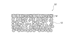
- FIG. 1 It is a schematic cross section which shows one aspect
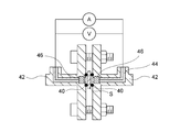
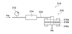
- 2 is a schematic cross-sectional view showing an electrochemical measurement system used in Examples 1 and 2.
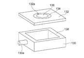
- FIG. It is a disassembled perspective view of the airtight container for measurement used in the denseness determination test of Examples 1 and 2.
- FIG. 6B is a schematic cross-sectional view of a sample holder used in the measurement system shown in FIG. 6A and its peripheral configuration.
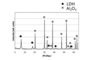
- 2 is an X-ray diffraction result of a functional layer manufactured in Example 1.
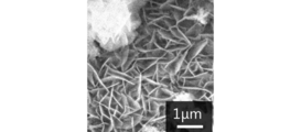
- FIG. 2 is an SEM image showing a surface microstructure of a functional layer produced in Example 1.
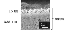
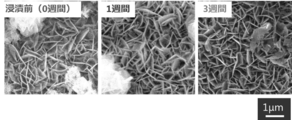
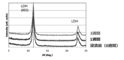
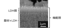
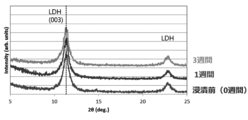
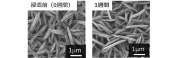
- 3 is a SEM image showing a cross-sectional microstructure of a functional layer manufactured in Example 1. It is a SEM image which shows the surface microstructure of the functional layer produced in Example 1 before immersion in KOH aqueous solution, after 1 week immersion, and after 3 weeks immersion. It is the X-ray-diffraction result of the functional layer produced in Example 1 before immersion in KOH aqueous solution, after 1 week immersion, and after 3 week immersion.
- FIG. 6 is a SEM image showing a surface microstructure of a functional layer produced in Example 2.
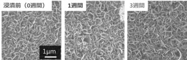
- 6 is a SEM image showing a cross-sectional microstructure of a functional layer fabricated in Example 2. It is a SEM image which shows the surface microstructure of the functional layer produced in Example 2 before immersion in KOH aqueous solution, after 1 week immersion, and after 3 weeks immersion. It is the X-ray-diffraction result of the functional layer produced in Example 2 before immersion in KOH aqueous solution, after 1 week immersion, and after 3 weeks immersion. It is a SEM image which shows the surface microstructure of the functional layer produced in Example 3 (comparison).
- Example 3 It is a SEM image which shows the cross-sectional microstructure of the functional layer produced in Example 3 (comparison). It is a SEM image which shows the surface microstructure of the functional layer of the functional layer produced in Example 3 (comparative) before immersion in KOH aqueous solution and after 1 week immersion. It is the X-ray-diffraction result of the functional layer produced in Example 3 (comparison) before immersion in KOH aqueous solution and after 1 week immersion. 6 is a SEM image showing a cross-sectional microstructure of a functional layer and a composite material produced in Example 4.
- the functional layer of the present invention is a layer containing layered double hydroxide (LDH), and this LDH has a concentration of 0.4 mol / L and 5 mol / L of hydroxide containing zinc oxide.
- LDH layered double hydroxide
- the surface microstructure and crystal structure do not change.
- the presence or absence of changes in the surface microstructure depends on the surface microstructure using an SEM (scanning electron microscope), and the presence or absence of changes in the crystal structure depends on crystal structure analysis using XRD (X-ray diffraction) (for example, (003) derived from LDH) This can be preferably performed depending on whether or not there is a peak shift.
- Potassium hydroxide is a typical strong alkaline substance, and the composition of the potassium hydroxide aqueous solution corresponds to a typical strong alkaline electrolyte of an alkaline secondary battery. Therefore, it can be said that the above evaluation method of immersing in such a strong alkaline electrolyte at a high temperature of 70 ° C. for a long period of 3 weeks is a severe alkali resistance test.
- the alkali secondary battery LDH is desired to have a high alkali resistance that hardly deteriorates even in a strong alkaline electrolyte.
- the functional layer of the present invention has excellent alkali resistance that the surface microstructure and crystal structure are not changed even by such severe alkali resistance tests.
- the functional layer of the present invention can also exhibit high ionic conductivity suitable for use as a separator for an alkaline secondary battery due to the inherent properties of LDH. That is, according to the present invention, it is possible to provide an LDH-containing functional layer that is excellent not only in ion conductivity but also in alkali resistance.
- LDH is composed of a plurality of hydroxide base layers and an intermediate layer interposed between the plurality of hydroxide base layers.
- the hydroxide base layer is mainly composed of metal elements (typically metal ions) and OH groups.
- the intermediate layer of LDH included in the functional layer is composed of an anion and H 2 O.
- the anion is a monovalent or higher anion, preferably a monovalent or divalent ion.
- the anion in LDH comprises OH - and / or CO 3 2- .
- the composition of LDH in the present invention is not particularly limited as long as the surface microstructure and the crystal structure are not changed by the alkali resistance evaluation described above. Further, as described above, LDH has excellent ionic conductivity due to its inherent properties.
- the hydroxide base layer of LDH is composed of Ni, Ti, OH groups and possibly inevitable impurities.
- the intermediate layer of LDH is composed of an anion and H 2 O.
- the alternate layered structure of the hydroxide basic layer and the intermediate layer itself is basically the same as the generally known alternate layered structure of LDH, but the functional layer of this embodiment is mainly composed of the hydroxide basic layer of LDH as Ni.
- an element for example, Al
- Ni in LDH can take the form of nickel ions.
- the nickel ions in LDH are typically considered to be Ni 2+ , but are not particularly limited because other valences such as Ni 3+ may also exist.
- Ti in LDH can take the form of titanium ions.
- the titanium ion in LDH is typically considered to be Ti 4+ , but is not particularly limited because other valences such as Ti 3+ may also exist.
- Inevitable impurities are optional elements that can be inevitably mixed in the manufacturing process, and can be mixed in LDH, for example, derived from raw materials and base materials.
- the hydroxide base layer is mainly composed of Ni 2+ , Ti 4+ and OH groups
- the corresponding LDH has the general formula: Ni 2+ 1-x Ti 4+ x (OH) 2 An - 2x / n ⁇ mH 2 O (wherein, a n-n-valent anion, n is an integer of 1 or more, preferably 1 or 2, 0 ⁇ x ⁇ 1, preferably 0.01 ⁇ x ⁇ 0.5, m is 0 or more, typically greater than 0 or 1 or more real number).
- the hydroxide base layer of LDH comprises Ni, Al, Ti and OH groups.
- the intermediate layer is composed of an anion and H 2 O.
- the alternating layered structure of the hydroxide basic layer and the intermediate layer itself is basically the same as the generally known layered structure of LDH, but the functional layer of this embodiment is configured such that the hydroxide basic layer of LDH is Ni, By comprising a predetermined element or ion containing Al, Ti and OH groups, excellent alkali resistance can be exhibited.
- Ni in LDH can take the form of nickel ions.
- the nickel ions in LDH are typically considered to be Ni 2+ , but are not particularly limited because other valences such as Ni 3+ may also exist.
- Al in LDH can take the form of aluminum ions.
- Aluminum ions in LDH are typically considered to be Al 3+ , but are not particularly limited because other valences are possible.
- Ti in LDH can take the form of titanium ions.
- the titanium ion in LDH is typically considered to be Ti 4+ , but is not particularly limited because other valences such as Ti 3+ may also exist.
- the hydroxide base layer may contain other elements or ions as long as it contains Ni, Al, Ti and OH groups. However, it is preferable that the hydroxide base layer contains Ni, Al, Ti, and OH groups as main components. That is, the hydroxide base layer is preferably mainly composed of Ni, Al, Ti and OH groups. Therefore, the hydroxide base layer is typically composed of Ni, Al, Ti, OH groups and possibly inevitable impurities.
- Inevitable impurities are optional elements that can be inevitably mixed in the manufacturing process, and can be mixed in LDH, for example, derived from raw materials and base materials.
- LDH for example, derived from raw materials and base materials.
- the hydroxide base layer is mainly composed of Ni 2+ , Al 3+ , Ti 4+ and OH groups
- the corresponding LDH has the general formula: Ni 2+ 1-xy Al 3+ x Ti 4+ y (OH) 2 A n ⁇ (x + 2y) / n ⁇ mH 2 O
- a n ⁇ is an n-valent anion
- n is an integer of 1 or more, preferably 1 or 2, and 0 ⁇ x ⁇ 1, preferably 0.01 ⁇ x ⁇ 0.5, 0 ⁇ y ⁇ 1, preferably 0.01 ⁇ y ⁇ 0.5, 0 ⁇ x + y ⁇ 1, m is 0 or more, typically 0.
- the functional layer (particularly LDH contained in the functional layer) preferably has hydroxide ion conductivity.
- the functional layer preferably has an ionic conductivity of 0.1 mS / cm or more, more preferably 0.5 mS / cm or more, and more preferably 1.0 mS / cm or more.
- the upper limit is not particularly limited, but is, for example, 10 mS / cm.
- Such high ionic conductivity is particularly suitable for battery applications.
- an LDH-containing functional layer having a low resistance can be provided. It is particularly advantageous in the application of LDH as a solid electrolyte separator for secondary batteries.
- the functional layer is provided on the porous substrate and / or is incorporated into the porous substrate. That is, according to a preferred aspect of the present invention, there is provided a composite material comprising a porous substrate and a functional layer provided on the porous substrate and / or incorporated into the porous substrate.
- a part of the functional layer 14 may be incorporated in the porous substrate 12 and the remaining part may be provided on the porous substrate 12.
- the portion of the functional layer 14 on the porous substrate 12 is a film-shaped portion made of an LDH film, and the portion of the functional layer 14 that is incorporated into the porous substrate 12 is composed of the porous substrate and LDH.
- the composite part typically has a form in which the pores of the porous substrate 12 are filled with LDH.
- the functional layer 14 ′ is mainly composed of the porous substrate 12 and LDH. It can be said that.
- the composite material 10 ′ and the functional layer 14 ′ shown in FIG. 2 are obtained by removing the film-like portion (LDH film) in the functional layer 14 from the composite material 10 shown in FIG. 1 by a known method such as polishing or cutting. Obtainable. 1 and 2, the functional layers 14 and 14 ′ are incorporated only in a part near the surface of the porous base material 12 and 12 ′. However, the functional layer is incorporated in any part of the porous base material. In addition, the functional layer may be incorporated over the whole or the entire thickness of the porous substrate.
- the porous base material in the composite material of the present invention is preferably capable of forming an LDH-containing functional layer on and / or in it, and the material and the porous structure are not particularly limited.
- the LDH-containing functional layer is formed on and / or in the porous substrate, but the LDH-containing functional layer is formed on the nonporous substrate, and then nonporous by various known methods.
- the porous substrate may be made porous.
- the porous base material has a porous structure having water permeability in that the electrolyte solution can reach the functional layer when incorporated in the battery as a battery separator.
- the porous substrate is preferably composed of at least one selected from the group consisting of ceramic materials, metal materials, and polymer materials, and more preferably selected from the group consisting of ceramic materials and polymer materials. It is composed of at least one kind. More preferably, the porous substrate is made of a ceramic material.
- the ceramic material include alumina, zirconia, titania, magnesia, spinel, calcia, cordierite, zeolite, mullite, ferrite, zinc oxide, silicon carbide, and any combination thereof, and more preferable.
- alumina e.g, yttria stabilized zirconia (YSZ)
- YSZ yttria stabilized zirconia
- Preferred examples of the metal material include aluminum, zinc, and nickel.
- Preferred examples of the polymer material include polystyrene, polyethersulfone, polypropylene, epoxy resin, polyphenylene sulfide, hydrophilic fluororesin (tetrafluorinated resin: PTFE, etc.), cellulose, nylon, polyethylene, and any combination thereof. Is mentioned. Any of the various preferred materials described above has alkali resistance as resistance to the electrolyte of the battery.
- the porous substrate is composed of a polymer material.
- the polymer porous substrate is 1) flexible (and therefore difficult to crack even if it is thin), 2) easy to increase porosity, 3) easy to increase conductivity (thickness while increasing porosity) 4) There is an advantage that it is easy to manufacture and handle.
- Particularly preferred polymer materials are polyolefins such as polypropylene and polyethylene, and polypropylene is most preferred from the viewpoints of excellent hot water resistance, acid resistance and alkali resistance and low cost.
- the functional layer is incorporated throughout the entire thickness direction of the porous substrate (for example, most or almost all the pores inside the porous substrate are filled with LDH). Are particularly preferred.
- the preferred thickness of the polymeric porous substrate is 5 to 200 ⁇ m, more preferably 5 to 100 ⁇ m, and still more preferably 5 to 30 ⁇ m.
- a microporous membrane commercially available as a lithium battery separator can be preferably used.
- the porous substrate preferably has an average pore size of at most 100 ⁇ m or less, more preferably at most 50 ⁇ m, for example, typically 0.001 to 1.5 ⁇ m, more typically 0.001. 1.25 ⁇ m, more typically 0.001 to 1.0 ⁇ m, particularly typically 0.001 to 0.75 ⁇ m, and most typically 0.001 to 0.5 ⁇ m.
- the average pore diameter can be measured by measuring the longest distance of the pores based on the electron microscope image of the surface of the porous substrate.
- the magnification of the electron microscope image used for this measurement is 20000 times or more. All the obtained pore diameters are arranged in order of size, and the top 15 points and the bottom 15 points are arranged in order from the average value, and 30 points per visual field are combined.
- the average pore diameter can be obtained by calculating an average value for two visual fields.
- a length measurement function of SEM software, image analysis software (for example, Photoshop, manufactured by Adobe) or the like can be used for the length measurement.
- the porous substrate preferably has a porosity of 10 to 60%, more preferably 15 to 55%, still more preferably 20 to 50%. By being within these ranges, it is possible to form an LDH-containing functional layer that is so dense that it does not have water permeability, while ensuring the desired water permeability and strength as a support for the porous substrate.
- the porosity of the porous substrate can be preferably measured by the Archimedes method. However, when the porous substrate is composed of a polymer material and the functional layer is incorporated over the entire area in the thickness direction of the porous substrate, the porosity of the porous substrate is preferably 30 to 60%, more Preferably it is 40 to 60%.
- the functional layer does not have air permeability. That is, the functional layer is preferably densified with LDH to such an extent that it does not have air permeability.
- non-breathable refers to an object to be measured in water when the breathability is evaluated by a “denseness determination test” employed in the examples described later or a method or configuration equivalent thereto. This means that even if helium gas is brought into contact with one surface side (that is, the functional layer and / or the porous substrate) with a differential pressure of 0.5 atm, generation of bubbles due to helium gas is not observed from the other surface side. .
- the functional layer or the composite material as a whole can selectively pass only hydroxide ions due to its hydroxide ion conductivity, and can exhibit a function as a battery separator.
- LDH solid electrolyte separator
- strength can be imparted by a porous substrate. Therefore, the LDH-containing functional layer can be thinned to reduce the resistance.
- the porous substrate can have water permeability and air permeability, the electrolyte can reach the LDH-containing functional layer when used as a battery solid electrolyte separator.
- the LDH-containing functional layer and composite material of the present invention are used as solid electrolyte separators applicable to various battery applications such as metal-air batteries (for example, zinc-air batteries) and other various zinc secondary batteries (for example, nickel-zinc batteries). It can be a very useful material.
- the functional layer or the composite material including the functional layer preferably has a He permeability per unit area of 10 cm / min ⁇ atm or less, more preferably 5.0 cm / min ⁇ atm or less, and even more preferably 1.0 cm / min. It is below min ⁇ atm. It can be said that the functional layer having the He transmittance within such a range has extremely high density. Therefore, the functional layer having a He permeability of 10 cm / min ⁇ atm or less can prevent a high level of passage of substances other than hydroxide ions when applied as a separator in an alkaline secondary battery. For example, in the case of a zinc secondary battery, permeation of zinc ions or zincate ions in the electrolytic solution can be extremely effectively suppressed.
- the He permeability is measured through a process of supplying He gas to one surface of the functional layer and allowing the He gas to pass through the functional layer, and a process of calculating the He permeability and evaluating the density of the functional layer.
- the He permeability is expressed by the following formula: F / (P ⁇ S), using the He gas permeation amount F per unit time, the differential pressure P applied to the functional layer when He gas permeates, and the membrane area S through which He gas permeates.
- H 2 gas is dangerous because it is a combustible gas.
- He gas permeability index defined by the above-described formula
- objective evaluation regarding the denseness can be easily performed regardless of differences in various sample sizes and measurement conditions. In this way, it is possible to simply, safely and effectively evaluate whether or not the functional layer has a sufficiently high density suitable for a zinc secondary battery separator.
- the measurement of the He permeability can be preferably performed according to the procedure shown in Evaluation 5 of Examples described later.
- LDH includes an aggregate of a plurality of plate-like particles (that is, LDH plate-like particles), and the plurality of plate-like particles are macroscopically such that the plate surface is a layer surface of the functional layer (the fine irregularities of the functional layer can be ignored). It is preferably oriented in a direction perpendicular to or obliquely intersecting the layer surface when observed.
- a functional layer when a functional layer is provided on a porous base material, a functional layer has a film-like part provided on a porous base material.
- the LDH constituting the film-like portion includes an aggregate of a plurality of plate-like particles (that is, LDH plate-like particles), and the plate-like particles have a plate surface whose surface is porous (porous). It is preferably oriented in a direction that intersects perpendicularly or obliquely with the surface of the porous base material when the microscopic unevenness due to the structure is macroscopically observed to a negligible extent.
- grains can exist also in the hole of a porous base material.
- the film-like part may further contain ceramic particles such as alumina particles as a filler, whereby the adhesion strength between the LDH of the film-like part and the substrate can be increased.
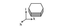
- the LDH crystal is known to have the form of a plate-like particle having a layered structure as shown in FIG. 3, but the above vertical or oblique orientation is extremely important for an LDH-containing functional layer (for example, an LDH dense film).
- an LDH-containing functional layer for example, an LDH dense film
- an oriented LDH-containing functional layer eg, an oriented LDH dense film
- the conductivity (S / cm) in the orientation direction is one digit higher than the conductivity (S / cm) in the direction perpendicular to the orientation direction. That is, the vertical or oblique orientation in the LDH-containing functional layer of the present invention indicates the conductivity anisotropy that the LDH oriented body can have in the layer thickness direction (that is, the direction perpendicular to the surface of the functional layer or porous substrate). As a result, the conductivity in the layer thickness direction can be maximized or significantly increased.
- the LDH-containing functional layer has a layer form, lower resistance than that of the bulk form LDH can be realized.
- the LDH-containing functional layer having such an orientation is easy to conduct hydroxide ions in the layer thickness direction.
- it is extremely suitable for use in functional membranes such as battery separators (eg, hydroxide ion conductive separators for zinc-air batteries) where high conductivity in the layer thickness direction and denseness are desired. Suitable.
- the functional layer preferably has a thickness of 100 ⁇ m or less, more preferably 75 ⁇ m or less, still more preferably 50 ⁇ m or less, particularly preferably 25 ⁇ m or less, and most preferably 5 ⁇ m or less. Such thinness can reduce the resistance of the functional layer.
- the thickness of the functional layer corresponds to the thickness of the film-like portion made of the LDH film.
- the thickness of the functional layer corresponds to the thickness of the composite portion composed of the porous substrate and LDH.
- a functional layer when a functional layer is formed over and in a porous base material, it corresponds to the total thickness of a film-like part (LDH film) and a composite part (porous base material and LDH).
- LDH film film-like part
- composite part porous base material and LDH
- the lower limit of the thickness of the LDH film is not particularly limited because it varies depending on the application, but in order to ensure a certain degree of rigidity desired as a functional film such as a separator, the thickness is preferably 1 ⁇ m or more, more preferably Is 2 ⁇ m or more.
- the manufacturing method of the LDH-containing functional layer and the composite material is not particularly limited, and the LDH-containing functional layer and the composite material are manufactured by appropriately changing various conditions of the known LDH-containing functional layer and composite material manufacturing method (see, for example, Patent Documents 1 and 2). be able to.
- a porous substrate is prepared, (2) a titanium oxide sol or a mixed sol of alumina and titania is applied to the porous substrate and heat-treated to form a titanium oxide layer or an alumina / titania layer, (3) The porous base material is immersed in a raw material aqueous solution containing nickel ions (Ni 2+ ) and urea, and (4) the porous base material is hydrothermally treated in the raw material aqueous solution to form the LDH-containing functional layer as the porous base material.
- the LDH-containing functional layer and the composite material can be produced.
- the raw material of LDH can be provided, but it can also function as a starting point for LDH crystal growth.
- the LDH-containing functional layer highly densified on the surface can be uniformly formed without unevenness.
- the presence of urea in the above step (3) raises the pH value due to the generation of ammonia in the solution utilizing the hydrolysis of urea, and the coexisting metal ions form hydroxides. LDH can be obtained. Further, since carbon dioxide is generated in the hydrolysis, LDH in which the anion is carbonate ion type can be obtained.
- the mixed sol of alumina and titania in (2) above it is preferable to perform the application to the base material in such a manner that the mixed sol permeates all or most of the inside of the base material. By doing so, it is possible to finally fill most or almost all the pores inside the porous substrate with LDH.
- preferred coating techniques include dip coating and filtration coating, with dip coating being particularly preferred.
- the adhesion amount of the mixed sol can be adjusted by adjusting the number of times of application such as dip coating. After the base material on which the mixed sol is applied by dip coating or the like is dried, the steps (3) and (4) may be performed.
- Evaluation 1 Identification of functional layer
- the crystal phase of the functional layer was measured with an X-ray diffractometer (RINT TTR III manufactured by Rigaku Corporation) under the measurement conditions of voltage: 50 kV, current value: 300 mA, measurement range: 10 to 70 °.
- an XRD profile was obtained.
- JCPDS card NO. Identification was performed using a diffraction peak of LDH (hydrotalcite compound) described in 35-0964.
- Evaluation 2 Observation of microstructure
- the surface microstructure of the functional layer was observed with a scanning electron microscope (SEM, JSM-6610LV, manufactured by JEOL) at an acceleration voltage of 10 to 20 kV. Further, after obtaining a cross-sectional polished surface of a functional layer (a film-shaped portion made of an LDH film and a composite portion made of LDH and a base material) with an ion milling device (manufactured by Hitachi High-Technologies Corporation, IM4000) The structure was observed by SEM under the same conditions as the observation of the surface microstructure.
- Evaluation 3 Elemental analysis evaluation (EDS) Polishing was performed with a cross section polisher (CP) so that the cross-section polished surface of the functional layer (a film-like portion made of an LDH film and a composite portion made of LDH and a base material) could be observed.
- FE-SEM ULTRA55, manufactured by Carl Zeiss
- a cross-sectional image of the functional layer was obtained in one field of view at a magnification of 10,000 times.
- Evaluation 4 Evaluation of alkali resistance Zinc oxide was dissolved in a 6 mol / L potassium hydroxide aqueous solution to obtain a 5 mol / L potassium hydroxide aqueous solution containing zinc oxide at a concentration of 0.4 mol / L. 15 ml of the aqueous potassium hydroxide solution thus obtained was placed in a Teflon (registered trademark) sealed container. A composite material having a size of 1 cm ⁇ 0.6 cm was placed on the bottom of the sealed container so that the functional layer faced upward, and the lid was closed. The composite material was then removed from the sealed container after holding at 70 ° C. (Examples 1 and 2) or 30 ° C. (Example 3) for 1 week (ie, 168 hours) or 3 weeks (ie, 504 hours). The removed composite material was dried overnight at room temperature. The obtained sample was observed for microstructure by SEM and crystal structure by XRD.
- Evaluation 5 Measurement of ion conductivity
- the conductivity of the functional layer in the electrolytic solution was measured as follows using an electrochemical measurement system shown in FIG.
- the composite material sample S porous substrate with LDH film
- the composite material sample S was sandwiched from both sides by a 1 mm thick silicone packing 40 and incorporated into a PTFE flange type cell 42 having an inner diameter of 6 mm.
- As the electrode 46 a # 100 mesh nickel wire mesh was incorporated into the cell 42 in a cylindrical shape having a diameter of 6 mm so that the distance between the electrodes was 2.2 mm.
- As the electrolytic solution 44 a 6 M KOH aqueous solution was filled in the cell 42.
- the frequency range is 1MHz to 0.1Hz
- the applied voltage is 10mV
- the real axis intercept was defined as the resistance of the composite material sample S (porous substrate with LDH film).
- the same measurement as described above was performed only on the porous substrate without the LDH film, and the resistance of only the porous substrate was also obtained.
- the difference between the resistance of the composite material sample S (porous substrate with LDH film) and the resistance of only the substrate was defined as the resistance of the LDH film.
- the conductivity was determined using the resistance of the LDH film and the film thickness and area of the LDH.
- Evaluation 6 Denseness determination test A denseness determination test was performed as follows in order to confirm that the functional layer does not have air permeability. First, as shown in FIGS. 5A and 5B, an acrylic container 130 without a lid and an alumina jig 132 having a shape and size that can function as a lid for the acrylic container 130 were prepared.
- the acrylic container 130 is formed with a gas supply port 130a for supplying gas therein.
- the alumina jig 132 is formed with an opening 132a having a diameter of 5 mm, and a sample placement recess 132b is formed along the outer periphery of the opening 132a.
- An epoxy adhesive 134 was applied to the depression 132b of the alumina jig 132, and the functional layer 136b side of the composite material sample 136 was placed on the depression 132b to adhere to the alumina jig 132 in an airtight and liquid-tight manner. Then, the alumina jig 132 to which the composite material sample 136 is bonded is adhered to the upper end of the acrylic container 130 in a gas-tight and liquid-tight manner using a silicone adhesive 138 so as to completely close the open portion of the acrylic container 130. A measurement sealed container 140 was obtained.
- the measurement sealed container 140 was placed in a water tank 142, and the gas supply port 130 a of the acrylic container 130 was connected to a pressure gauge 144 and a flow meter 146 so that helium gas could be supplied into the acrylic container 130.
- Water 143 was put into the water tank 142 and the measurement sealed container 140 was completely submerged.
- the inside of the measurement sealed container 140 is sufficiently airtight and liquid tight, and the functional layer 136b side of the composite material sample 136 is exposed to the internal space of the measurement sealed container 140, while the composite material sample
- the porous substrate 136 a side of 136 is in contact with the water in the water tank 142.
- helium gas was introduced into the measurement sealed container 140 into the acrylic container 130 via the gas supply port 130a.
- the pressure gauge 144 and the flow meter 146 are controlled so that the differential pressure inside and outside the functional layer 136a becomes 0.5 atm (that is, the pressure applied to the side in contact with the helium gas is 0.5 atm higher than the water pressure applied to the opposite side). Whether or not helium gas bubbles were generated in the water from the composite material sample 136 was observed. As a result, when generation
- He permeation measurement A He permeation test was performed as follows to evaluate the denseness of the functional layer from the viewpoint of He permeation.
- the He permeability measurement system 310 is a function in which He gas from a gas cylinder filled with He gas is supplied to the sample holder 316 via the pressure gauge 312 and the flow meter 314 (digital flow meter), and is held in the sample holder 316.
- the layer 318 was configured to be transmitted from one surface to the other surface and discharged.
- the sample holder 316 has a structure including a gas supply port 316a, a sealed space 316b, and a gas discharge port 316c, and was assembled as follows. First, an adhesive 322 was applied along the outer periphery of the functional layer 318 and attached to a jig 324 (made of ABS resin) having an opening at the center. Support members 328a and 328b (made of PTFE) provided with gaskets made of butyl rubber as sealing members 326a and 326b at the upper and lower ends of the jig 324 and further provided with openings formed from flanges from the outside of the sealing members 326a and 326b. ).
- the sealed space 316b was partitioned by the functional layer 318, the jig 324, the sealing member 326a, and the support member 328a.
- the functional layer 318 is in the form of a composite material formed on the porous substrate 320, but the functional layer 318 is disposed so that the functional layer 318 side faces the gas supply port 316a.
- the support members 328a and 328b were firmly fastened to each other by fastening means 330 using screws so that He gas leakage did not occur from a portion other than the gas discharge port 316c.
- the gas supply pipe 34 was connected to the gas supply port 316a of the sample holder 316 assembled in this way via a joint 332.
- He gas was supplied to the He permeability measurement system 310 via the gas supply pipe 334 and permeated through the functional layer 318 held in the sample holder 316.
- the gas supply pressure and the flow rate were monitored by the pressure gauge 312 and the flow meter 314.
- the He permeability was calculated. Calculation of He permeability, permeation amount F (cm 3 / min) of He gas per unit time, the differential pressure P (atm) applied to the functional layer when the He gas permeation, and the membrane area S (cm which He gas passes 2 ) and calculated by the formula of F / (P ⁇ S).
- the permeation amount F (cm 3 / min) of He gas was directly read from the flow meter 314. Further, as the differential pressure P, the gauge pressure read from the pressure gauge 312 was used. The He gas was supplied so that the differential pressure P was in the range of 0.05 to 0.90 atm.
- Example 1 A functional layer and a composite material containing Ni and Ti-containing LDH were prepared and evaluated by the following procedure.
- porous substrate 70 parts by weight of a dispersion medium (xylene: butanol 1: 1) and binder (polyvinyl butyral: Sekisui Chemical) with respect to 100 parts by weight of alumina powder (AES-12, manufactured by Sumitomo Chemical Co., Ltd.) BM-2 manufactured by Kogyo Co., Ltd. 11.1 parts by weight, 5.5 parts by weight of a plasticizer (DOP: manufactured by Kurokin Kasei Co., Ltd.), and 2.9 parts by weight of a dispersant (Rheodor SP-O30 manufactured by Kao Corporation)
- a dispersant Rosodor SP-O30 manufactured by Kao Corporation
- the slurry was molded into a sheet shape on a PET film using a tape molding machine so that the film thickness after drying was 220 ⁇ m to obtain a sheet molded body.
- the obtained molded body was cut out to have a size of 2.0 cm ⁇ 2.0 cm ⁇ thickness 0.022 cm and fired at 1300 ° C. for 2 hours to obtain an alumina porous substrate.
- the porosity of the porous substrate was measured by the Archimedes method by a technique using image processing, and it was 40%.
- the average pore diameter of the porous substrate was measured, it was 0.3 ⁇ m.
- the average pore diameter was measured by measuring the longest distance of the pores based on an electron microscope (SEM) image of the surface of the porous substrate. The magnification of the electron microscope (SEM) image used for this measurement is 20000 times. All obtained pore diameters are arranged in order of size, and the top 15 points and the bottom 15 points are arranged in order from the average value. An average value for two visual fields was calculated at 30 points to obtain an average pore diameter. For length measurement, the length measurement function of SEM software was used.
- Titanium oxide sol coat on porous substrate 0.2 ml of titanium oxide sol (M-6, manufactured by Taki Chemical Co., Ltd.) was applied onto the alumina porous substrate obtained in (1) above by spin coating. did.
- the titanium oxide sol was dropped onto the substrate rotated at 8000 rpm, and after 5 seconds, the rotation was stopped. The substrate was allowed to stand on a hot plate heated to 100 ° C. and dried for 1 minute. Thereafter, heat treatment was performed at 200 ° C. in an electric furnace.
- the titanium oxide layer thus formed had a thickness of about 100 nm.
- Nickel nitrate hexahydrate Ni (NO 3 ) 2 ⁇ 6H 2 O, manufactured by Kanto Chemical Co., Inc.
- urea ((NH 2 ) 2 CO, manufactured by Sigma-Aldrich)
- Nickel nitrate hexahydrate was weighed so as to be 0.015 mol / L, put into a beaker, and ion-exchanged water was added thereto to make a total volume of 75 ml.
- Urea weighed in a ratio of urea / NO 3 ⁇ (molar ratio) 16 was added thereto, and further stirred to obtain a raw material aqueous solution.
- the substrate was taken out from the sealed container, washed with ion-exchanged water, dried at 70 ° C. for 10 hours, and a part of the functional layer containing LDH was incorporated into the porous substrate. Got in shape.
- the thickness of the obtained functional layer was about 5 ⁇ m (including the thickness of the portion incorporated in the porous substrate).
- Evaluation results Evaluations 1 to 7 were performed on the obtained functional layers or composite materials. The results were as follows.
- -Evaluation 1 The XRD profile shown in FIG. 7 was obtained. From this XRD profile, it was identified that the functional layer was LDH (hydrotalcite compound). FIG. 7 also shows a peak derived from alumina constituting the porous substrate.
- -Evaluation 2 The SEM images of the surface microstructure and the cross-sectional microstructure of the functional layer were as shown in FIGS. 8A and 8B, respectively. As shown in FIG. 8B, it was found that the functional layer was composed of a film-shaped portion made of an LDH film and a composite portion made of LDH and a porous substrate located under the film-shaped portion.
- the LDH constituting the film-like portion is composed of an aggregate of a plurality of plate-like particles, and the plurality of plate-like particles have their plate surfaces on the surface of the porous substrate (fine irregularities due to the porous structure). It was oriented in a direction perpendicular to or obliquely intersecting the surface of the porous substrate when observed macroscopically to a negligible extent.
- the composite part constituted a dense layer by filling the pores of the porous substrate with LDH.
- -Evaluation 3 As a result of EDS elemental analysis, LDH constituent elements C, Ti, and Ni were detected in both LDH contained in the functional layer, that is, the LDH film on the substrate surface and the LDH portion in the substrate. .
- Example 2 A functional layer and a composite material containing Ni, Al, and Ti-containing LDH were prepared and evaluated by the following procedure.
- porous substrate 70 parts by weight of a dispersion medium (xylene: butanol 1: 1) and binder (polyvinyl butyral: Sekisui Chemical Co., Ltd.) with respect to 100 parts by weight of zirconia powder (manufactured by Tosoh Corporation, TZ-8YS) BM-2) manufactured by Co., Ltd. 11.1 parts by weight, 5.5 parts by weight of plasticizer (DOP: manufactured by Kurokin Kasei Co., Ltd.)
- DOP manufactured by Kurokin Kasei Co., Ltd.
- the slurry was molded into a sheet shape on a PET film using a tape molding machine so that the film thickness after drying was 220 ⁇ m to obtain a sheet molded body.
- the obtained molded body was cut out to have a size of 2.0 cm ⁇ 2.0 cm ⁇ thickness 0.022 cm and baked at 1100 ° C. for 2 hours to obtain a zirconia porous substrate.
- the porosity of the porous substrate was measured by the Archimedes method and found to be 40%.
- the average pore diameter of the porous substrate was measured, it was 0.2 ⁇ m.
- the average pore diameter was measured by measuring the longest distance of the pores based on an electron microscope (SEM) image of the surface of the porous substrate. The magnification of the electron microscope (SEM) image used for this measurement is 20000 times. All obtained pore diameters are arranged in order of size, and the top 15 points and the bottom 15 points are arranged in order from the average value. An average value for two visual fields was calculated at 30 points to obtain an average pore diameter. For length measurement, the length measurement function of SEM software was used.
- Alumina / titania sol coating on porous substrate Amorphous alumina solution (Al-ML15, manufactured by Taki Chemical Co., Ltd.) and titanium oxide sol solution (M-6, manufactured by Taki Chemical Co., Ltd.) was mixed to make a mixed sol.
- 0.2 ml of the mixed sol was applied onto the zirconia porous substrate obtained in (1) above by spin coating. In spin coating, the mixed sol was dropped onto the substrate rotated at 8000 rpm, and the rotation was stopped 5 seconds later. The substrate was allowed to stand on a hot plate heated to 100 ° C. and dried for 1 minute. Thereafter, heat treatment was performed at 300 ° C. in an electric furnace. The thickness of the layer thus formed was about 1 ⁇ m.
- Nickel nitrate hexahydrate Ni (NO 3 ) 2 ⁇ 6H 2 O, manufactured by Kanto Chemical Co., Inc.
- urea ((NH 2 ) 2 CO, manufactured by Sigma-Aldrich)
- Nickel nitrate hexahydrate was weighed so as to be 0.015 mol / L, put into a beaker, and ion-exchanged water was added thereto to make a total volume of 75 ml.
- Urea weighed in a ratio of urea / NO 3 ⁇ (molar ratio) 16 was added thereto, and further stirred to obtain a raw material aqueous solution.
- the substrate was taken out from the sealed container, washed with ion-exchanged water, dried at 70 ° C. for 10 hours, and a part of the functional layer containing LDH was incorporated into the porous substrate. Got in shape.
- the thickness of the obtained functional layer was about 5 ⁇ m (including the thickness of the portion incorporated in the porous substrate).
- Evaluation results Evaluations 1 to 7 were performed on the obtained functional layers or composite materials. The results were as follows.
- -Evaluation 1 The XRD profile shown in FIG. 11 was obtained. From this XRD profile, it was identified that the functional layer was LDH (hydrotalcite compound). FIG. 11 also shows zirconia-derived peaks constituting the porous substrate.
- -Evaluation 2 The SEM images of the surface microstructure and the cross-sectional microstructure of the functional layer were as shown in FIGS. 12A and 12B, respectively. As shown in FIG. 12B, it was found that the functional layer was composed of a film-shaped portion made of an LDH film and a composite portion made of LDH and a porous substrate located under the film-shaped portion.
- the LDH constituting the film-like portion is composed of an aggregate of a plurality of plate-like particles, and the plurality of plate-like particles have their plate surfaces on the surface of the porous substrate (fine irregularities due to the porous structure). It was oriented in a direction perpendicular to or obliquely intersecting the surface of the porous substrate when observed macroscopically to a negligible extent.
- the composite part constituted a dense layer by filling the pores of the porous substrate with LDH.
- -Evaluation 3 As a result of EDS elemental analysis, LDH constituent elements C, Al, Ti, and Ni are detected in the LDH contained in the functional layer, that is, the LDH film on the substrate surface and the LDH portion in the substrate.
- Example 3 (Comparison) A functional layer and a composite material containing Mg and Al-containing LDH were prepared and evaluated by the following procedure.
- porous substrate made of alumina was produced in the same manner as in step (1) in Example 1.
- magnesium nitrate hexahydrate (Mg (NO 3) 2 ⁇ 6H 2 O, manufactured by Kanto Chemical Co., Inc.), aluminum nitrate nonahydrate (Al (NO 3) 3 ⁇ 9H 2 O, manufactured by Kanto Chemical Co., Ltd.) and urea ((NH 2 ) 2 CO, manufactured by Sigma-Aldrich) were prepared.
- Mg (NO 3) 2 ⁇ 6H 2 O manufactured by Kanto Chemical Co., Inc.
- Al (NO 3) 3 ⁇ 9H 2 O manufactured by Kanto Chemical Co., Ltd.
- urea ((NH 2 ) 2 CO, manufactured by Sigma-Aldrich)
- ion exchange water was added to make a total volume of 70 ml.
- the substrate was taken out from the sealed container, washed with ion-exchanged water, dried at 70 ° C. for 10 hours, and a part of the functional layer containing LDH was incorporated into the porous substrate. Got in shape.
- the thickness of the functional layer obtained was about 3 ⁇ m (including the thickness of the portion incorporated in the porous substrate).
- Evaluation results Evaluations 1 to 7 were performed on the obtained functional layers or composite materials. The results were as follows. -Evaluation 1: From the obtained XRD profile, it was identified that the functional layer was LDH (hydrotalcite compound). -Evaluation 2: The SEM images of the surface microstructure and the cross-sectional microstructure of the functional layer were as shown in FIGS. 15A and 15B, respectively. In almost the same manner as the functional layers obtained in Examples 1 and 2, a functional layer composed of a film-shaped portion made of an LDH film and a composite portion made of LDH and a porous substrate located under the film-shaped portion is provided. Observed.
- -Evaluation 3 As a result of EDS elemental analysis, LDH constituent elements C, Mg, and Al were detected in both the LDH contained in the functional layer, that is, the LDH film on the substrate surface and the LDH portion in the substrate. . That is, Mg and Al are constituent elements of the hydroxide basic layer, while C corresponds to CO 3 2 ⁇ which is an anion constituting the intermediate layer of LDH.
- -Evaluation 4 The SEM image which image
- the functional layer of Example 3 is inferior in alkali resistance to the functional layers of Examples 1 and 2, that is, the functional layers of Examples 1 and 2 which are examples of the present invention are more than the functional layer of Example 3 which is a comparative example. It was found to be excellent in alkali resistance.
- -Evaluation 5 The conductivity of the functional layer was 2.0 mS / cm.
- -Evaluation 6 It was confirmed that the functional layer and the composite material have high denseness that does not have air permeability.
- -Evaluation 7 He permeability of the functional layer and the composite material was 0.0 cm / min ⁇ atm.
- Example 4 Using the polymer porous substrate, a functional layer and a composite material containing Ni, Al, and Ti-containing LDH were produced and evaluated by the following procedures.
- a commercially available polypropylene porous substrate having a porosity of 50%, an average pore diameter of 0.1 ⁇ m and a thickness of 20 ⁇ m is set to a size of 2.0 cm ⁇ 2.0 cm. Cut out.
- the mixed sol was applied to the substrate prepared in (1) above by dip coating. The dip coating was performed by immersing the substrate in 100 ml of the mixed sol and then pulling it up vertically and drying it in a dryer at 90 ° C. for 5 minutes.
- Evaluation results Evaluations 1 to 7 were performed on the obtained functional layers or composite materials. The results were as follows. -Evaluation 1: From the obtained XRD profile, it was identified that the functional layer was LDH (hydrotalcite compound). -Evaluation 2: The SEM image of the cross-sectional microstructure of the functional layer or composite material was as shown in FIG. As can be seen from FIG. 18, it was observed that the functional layer was incorporated over the entire region in the thickness direction of the porous substrate, that is, the pores of the porous substrate were uniformly filled with LDH.
- -Evaluation 3 As a result of EDS elemental analysis, LDH constituent elements C, Al, Ti, and Ni are detected in the LDH contained in the functional layer, that is, the LDH film on the substrate surface and the LDH portion in the substrate. It was done. That is, Al, Ti and Ni are constituent elements of the hydroxide basic layer, while C corresponds to CO 3 2 ⁇ which is an anion constituting the intermediate layer of LDH.
- -Evaluation 4 Even after being immersed in an aqueous solution of potassium hydroxide at 70 ° C for 3 to 7 weeks, the microstructure of the functional layers of Examples 1 to 5 did not change.
- -Evaluation 5 The conductivity of the functional layer was 2.0 mS / cm, which was the same as in Examples 1 to 3 described above.
- -Evaluation 6 It was confirmed that the functional layer and the composite material have high denseness that does not have air permeability.
- -Evaluation 7 He permeability of the functional layer and the composite material was 0.0 cm / min ⁇ atm.
Abstract
Provided are: a functional layer including a layered double hydroxide (LDH), said functional layer exhibiting not only excellent ion conductivity, but also excellent alkali resistance; and a composite material provided with said functional layer. The functional layer includes a LDH, and has hydroxide ion conductivity. When the LDH is immersed in a 5 mol/L aqueous potassium hydroxide solution including zinc oxide at a concentration of 0.4 mol/L, for three weeks at 70˚C, no changes occur in the surface microstructure and the crystal structure.
Description
本発明は、層状複水酸化物を含む機能層及び複合材料に関する。
The present invention relates to a functional layer and a composite material containing a layered double hydroxide.
層状複水酸化物(以下、LDHともいう)は、積み重なった水酸化物基本層の間に、中間層として交換可能な陰イオン及びH2Oを有する物質であり、その特徴を活かして触媒や吸着剤、耐熱性向上のための高分子中の分散剤等として利用されている。
Layered double hydroxide (hereinafter also referred to as LDH) is a substance having exchangeable anions and H 2 O as an intermediate layer between stacked hydroxide basic layers. It is used as an adsorbent, a dispersant in a polymer for improving heat resistance, and the like.
また、LDHは水酸化物イオンを伝導する材料としても注目され、アルカリ形燃料電池の電解質や亜鉛空気電池の触媒層への添加についても検討されている。特に、近年、ニッケル亜鉛二次電池、亜鉛空気二次電池等のアルカリ二次電池用の固体電解質セパレータとしてのLDHの利用も提案されており、かかるセパレータ用途に適したLDH含有機能層を備えた複合材料が知られている。例えば、特許文献1(国際公開第2015/098610号)には、多孔質基材と、多孔質基材上及び/又は中に形成される透水性を有しないLDH含有機能層とを備えた複合材料が開示されており、LDH含有機能層が、一般式:M2+
1-xM3+
x(OH)2An-
x/n・mH2O(式中、M2+はMg2+等の2価の陽イオン、M3+はAl3+等の3価の陽イオンであり、An-はOH-、CO3
2-等のn価の陰イオン、nは1以上の整数、xは0.1~0.4であり、mは0以上である)で表されるLDHを含むことが記載されている。特許文献1に開示されるLDH含有機能層は、透水性を有しない程に緻密化されているため、セパレータとして用いた場合に、アルカリ亜鉛二次電池の実用化の障壁となっている亜鉛デンドライト進展や、亜鉛空気電池における空気極からの二酸化炭素の侵入を阻止することができる。
LDH is also attracting attention as a material that conducts hydroxide ions, and its addition to the electrolyte of alkaline fuel cells and the catalyst layer of zinc-air cells is also being studied. In particular, in recent years, the use of LDH as a solid electrolyte separator for alkaline secondary batteries such as nickel-zinc secondary batteries and zinc-air secondary batteries has been proposed, and an LDH-containing functional layer suitable for such separator applications is provided. Composite materials are known. For example, Patent Document 1 (International Publication No. 2015/098610) discloses a composite including a porous substrate and an LDH-containing functional layer that does not have water permeability and is formed on and / or in the porous substrate. The material is disclosed, and the LDH-containing functional layer has a general formula: M 2+ 1-x M 3+ x (OH) 2 A n− x / n · mH 2 O (where M 2+ is 2 such as Mg 2+) A valent cation, M 3+ is a trivalent cation such as Al 3+ , A n− is an n-valent anion such as OH − , CO 3 2− , n is an integer of 1 or more, and x is 0. 1 to 0.4, and m is 0 or more). Since the LDH-containing functional layer disclosed in Patent Document 1 is so dense that it does not have water permeability, when used as a separator, a zinc dendrite that has become a barrier to practical use of alkaline zinc secondary batteries Progress and carbon dioxide intrusion from the air electrode in the zinc-air battery can be prevented.
しかしながら、LDHが適用されるアルカリ二次電池(例えば金属空気電池やニッケル亜鉛電池)の電解液には、高い水酸化物イオン伝導度が要求され、それ故、pHが14程度で強アルカリ性のKOH水溶液が用いられることが望まれる。このため、LDHにはこのような強アルカリ性電解液中においても殆ど劣化しないといった高度な耐アルカリ性が望まれる。この点、特許文献2(国際公開第2016/51934号)には、上述した一般式のM2+及び/又はM3+に対応する金属元素(例えばAl)を含む金属化合物を電解液に溶解させておくことでLDHの電解液による浸食が抑制されるように構成された、LDH含有電池が提案されている。
However, an alkaline secondary battery (for example, a metal-air battery or a nickel-zinc battery) to which LDH is applied requires a high hydroxide ion conductivity, and therefore has a pH of about 14 and a strong alkaline KOH. It is desirable to use an aqueous solution. For this reason, LDH is desired to have a high alkali resistance that hardly deteriorates even in such a strong alkaline electrolyte. In this regard, in Patent Document 2 (International Publication No. 2016/51934), a metal compound containing a metal element (for example, Al) corresponding to the above-described general formula M 2+ and / or M 3+ is dissolved in an electrolytic solution. There has been proposed an LDH-containing battery that is configured so that erosion of the LDH by the electrolyte is suppressed.
本発明者らは、今般、イオン伝導性のみならず耐アルカリ性にも優れたLDH含有機能層を提供できるとの知見を得た。
The inventors of the present invention have recently found that it is possible to provide an LDH-containing functional layer that is excellent not only in ion conductivity but also in alkali resistance.
したがって、本発明の目的は、イオン伝導性のみならず耐アルカリ性にも優れたLDH含有機能層及びそれを備えた複合材料を提供することにある。
Therefore, an object of the present invention is to provide an LDH-containing functional layer that is excellent not only in ion conductivity but also in alkali resistance, and a composite material including the same.
本発明の一態様によれば、層状複水酸化物を含む機能層であって、
前記層状複水酸化物は、0.4mol/Lの濃度で酸化亜鉛を含む5mol/Lの水酸化カリウム水溶液中に70℃で3週間浸漬させた場合に、表面微構造及び結晶構造の変化が生じない、機能層が提供される。 According to one aspect of the present invention, a functional layer comprising a layered double hydroxide,
When the layered double hydroxide is immersed in a 5 mol / L potassium hydroxide aqueous solution containing zinc oxide at a concentration of 0.4 mol / L at 70 ° C. for 3 weeks, the surface microstructure and crystal structure change. A functional layer that does not occur is provided.
本発明の他の一態様によれば、多孔質基材と、
前記多孔質基材上に設けられ、且つ/又は前記多孔質基材中に組み込まれる、前記機能層と、
を含む、複合材料が提供される。 According to another aspect of the invention, a porous substrate;
The functional layer provided on the porous substrate and / or incorporated into the porous substrate;
A composite material is provided comprising:
前記多孔質基材上に設けられ、且つ/又は前記多孔質基材中に組み込まれる、前記機能層と、
を含む、複合材料が提供される。 According to another aspect of the invention, a porous substrate;
The functional layer provided on the porous substrate and / or incorporated into the porous substrate;
A composite material is provided comprising:
本発明の他の一態様によれば、前記機能層又は前記複合材料をセパレータとして備えた電池が提供される。
According to another aspect of the present invention, a battery including the functional layer or the composite material as a separator is provided.
LDH含有機能層及び複合材料
本発明の機能層は、層状複水酸化物(LDH)を含む層であり、このLDHは、0.4mol/Lの濃度で酸化亜鉛を含む5mol/Lの水酸化カリウム水溶液中に70℃で3週間(すなわち504時間)浸漬させた場合に、表面微構造及び結晶構造の変化が生じないものである。表面微構造の変化の有無はSEM(走査型電子顕微鏡)を用いた表面微構造により、結晶構造の変化の有無はXRD(X線回折)を用いた結晶構造解析(例えばLDH由来の(003)ピークのシフトの有無)により、好ましく行うことができる。水酸化カリウムは代表的な強アルカリ物質であり、上記水酸化カリウム水溶液の組成はアルカリ二次電池の代表的な強アルカリ電解液に相当するものである。したがって、かかる強アルカリ電解液に70℃もの高温で3週間もの長期間浸漬させるという上記評価手法は、過酷な耐アルカリ性試験であるといえる。前述のとおり、アルカリ二次電池用LDHには強アルカリ性電解液中においても殆ど劣化しないといった高度な耐アルカリ性が望まれる。この点、本発明の機能層は、かかる過酷な耐アルカリ性試験によっても表面微構造及び結晶構造の変化が生じないという、優れた耐アルカリ性を有するものである。そうでありながらも、本発明の機能層は、LDH固有の性質に起因して、アルカリ二次電池用セパレータとしての使用に適した高いイオン伝導性も呈することができる。すなわち、本発明によれば、イオン伝導性のみならず耐アルカリ性にも優れたLDH含有機能層を提供することができる。 LDH-containing functional layer and composite material The functional layer of the present invention is a layer containing layered double hydroxide (LDH), and this LDH has a concentration of 0.4 mol / L and 5 mol / L of hydroxide containing zinc oxide. When immersed in an aqueous potassium solution at 70 ° C. for 3 weeks (ie, 504 hours), the surface microstructure and crystal structure do not change. The presence or absence of changes in the surface microstructure depends on the surface microstructure using an SEM (scanning electron microscope), and the presence or absence of changes in the crystal structure depends on crystal structure analysis using XRD (X-ray diffraction) (for example, (003) derived from LDH) This can be preferably performed depending on whether or not there is a peak shift. Potassium hydroxide is a typical strong alkaline substance, and the composition of the potassium hydroxide aqueous solution corresponds to a typical strong alkaline electrolyte of an alkaline secondary battery. Therefore, it can be said that the above evaluation method of immersing in such a strong alkaline electrolyte at a high temperature of 70 ° C. for a long period of 3 weeks is a severe alkali resistance test. As described above, the alkali secondary battery LDH is desired to have a high alkali resistance that hardly deteriorates even in a strong alkaline electrolyte. In this respect, the functional layer of the present invention has excellent alkali resistance that the surface microstructure and crystal structure are not changed even by such severe alkali resistance tests. Nevertheless, the functional layer of the present invention can also exhibit high ionic conductivity suitable for use as a separator for an alkaline secondary battery due to the inherent properties of LDH. That is, according to the present invention, it is possible to provide an LDH-containing functional layer that is excellent not only in ion conductivity but also in alkali resistance.
本発明の機能層は、層状複水酸化物(LDH)を含む層であり、このLDHは、0.4mol/Lの濃度で酸化亜鉛を含む5mol/Lの水酸化カリウム水溶液中に70℃で3週間(すなわち504時間)浸漬させた場合に、表面微構造及び結晶構造の変化が生じないものである。表面微構造の変化の有無はSEM(走査型電子顕微鏡)を用いた表面微構造により、結晶構造の変化の有無はXRD(X線回折)を用いた結晶構造解析(例えばLDH由来の(003)ピークのシフトの有無)により、好ましく行うことができる。水酸化カリウムは代表的な強アルカリ物質であり、上記水酸化カリウム水溶液の組成はアルカリ二次電池の代表的な強アルカリ電解液に相当するものである。したがって、かかる強アルカリ電解液に70℃もの高温で3週間もの長期間浸漬させるという上記評価手法は、過酷な耐アルカリ性試験であるといえる。前述のとおり、アルカリ二次電池用LDHには強アルカリ性電解液中においても殆ど劣化しないといった高度な耐アルカリ性が望まれる。この点、本発明の機能層は、かかる過酷な耐アルカリ性試験によっても表面微構造及び結晶構造の変化が生じないという、優れた耐アルカリ性を有するものである。そうでありながらも、本発明の機能層は、LDH固有の性質に起因して、アルカリ二次電池用セパレータとしての使用に適した高いイオン伝導性も呈することができる。すなわち、本発明によれば、イオン伝導性のみならず耐アルカリ性にも優れたLDH含有機能層を提供することができる。 LDH-containing functional layer and composite material The functional layer of the present invention is a layer containing layered double hydroxide (LDH), and this LDH has a concentration of 0.4 mol / L and 5 mol / L of hydroxide containing zinc oxide. When immersed in an aqueous potassium solution at 70 ° C. for 3 weeks (ie, 504 hours), the surface microstructure and crystal structure do not change. The presence or absence of changes in the surface microstructure depends on the surface microstructure using an SEM (scanning electron microscope), and the presence or absence of changes in the crystal structure depends on crystal structure analysis using XRD (X-ray diffraction) (for example, (003) derived from LDH) This can be preferably performed depending on whether or not there is a peak shift. Potassium hydroxide is a typical strong alkaline substance, and the composition of the potassium hydroxide aqueous solution corresponds to a typical strong alkaline electrolyte of an alkaline secondary battery. Therefore, it can be said that the above evaluation method of immersing in such a strong alkaline electrolyte at a high temperature of 70 ° C. for a long period of 3 weeks is a severe alkali resistance test. As described above, the alkali secondary battery LDH is desired to have a high alkali resistance that hardly deteriorates even in a strong alkaline electrolyte. In this respect, the functional layer of the present invention has excellent alkali resistance that the surface microstructure and crystal structure are not changed even by such severe alkali resistance tests. Nevertheless, the functional layer of the present invention can also exhibit high ionic conductivity suitable for use as a separator for an alkaline secondary battery due to the inherent properties of LDH. That is, according to the present invention, it is possible to provide an LDH-containing functional layer that is excellent not only in ion conductivity but also in alkali resistance.
一般的に知られているように、LDHは、複数の水酸化物基本層と、これら複数の水酸化物基本層間に介在する中間層とから構成される。水酸化物基本層は主として金属元素(典型的には金属イオン)とOH基で構成される。機能層に含まれるLDHの中間層は、陰イオン及びH2Oで構成される。陰イオンは1価以上の陰イオン、好ましくは1価又は2価のイオンである。好ましくは、LDH中の陰イオンはOH-及び/又はCO3
2-を含む。本発明におけるLDHは上述した耐アルカリ性評価により表面微構造及び結晶構造の変化が生じないものであれば、その組成は特に限定されない。また、上述したとおり、LDHはその固有の性質に起因して優れたイオン伝導性を有する。
As is generally known, LDH is composed of a plurality of hydroxide base layers and an intermediate layer interposed between the plurality of hydroxide base layers. The hydroxide base layer is mainly composed of metal elements (typically metal ions) and OH groups. The intermediate layer of LDH included in the functional layer is composed of an anion and H 2 O. The anion is a monovalent or higher anion, preferably a monovalent or divalent ion. Preferably, the anion in LDH comprises OH - and / or CO 3 2- . The composition of LDH in the present invention is not particularly limited as long as the surface microstructure and the crystal structure are not changed by the alkali resistance evaluation described above. Further, as described above, LDH has excellent ionic conductivity due to its inherent properties.
本発明の好ましい態様によれば、LDHの水酸化物基本層は、Ni、Ti、OH基、及び場合により不可避不純物で構成される。LDHの中間層は、上述のとおり、陰イオン及びH2Oで構成される。水酸化物基本層と中間層の交互積層構造自体は一般的に知られるLDHの交互積層構造と基本的に同じであるが、本態様の機能層は、LDHの水酸化物基本層を主としてNi、Ti及びOH基で構成することで、優れた耐アルカリ性を呈することができる。その理由は必ずしも定かではないが、本態様のLDHにはアルカリ溶液に溶出しやすいと考えられる元素(例えばAl)が意図的又は積極的に添加されていないためと考えられる。そうでありながらも、本態様の機能層は、アルカリ二次電池用セパレータとしての使用に適した高いイオン伝導性も呈することができる。LDH中のNiはニッケルイオンの形態を採りうる。LDH中のニッケルイオンは典型的にはNi2+であると考えられるが、Ni3+等の他の価数もありうるため、特に限定されない。LDH中のTiはチタンイオンの形態を採りうる。LDH中のチタンイオンは典型的にはTi4+であると考えられるが、Ti3+等の他の価数もありうるため、特に限定されない。不可避不純物は製法上不可避的に混入されうる任意元素であり、例えば原料や基材に由来してLDH中に混入しうる。上記のとおり、Ni及びTiの価数は必ずしも定かではないため、LDHを一般式で厳密に特定することは非実際的又は不可能である。仮に水酸化物基本層が主としてNi2+、Ti4+及びOH基で構成されるものと想定した場合には、対応するLDHは、一般式:Ni2+
1-xTi4+
x(OH)2An-
2x/n・mH2O(式中、An-はn価の陰イオン、nは1以上の整数、好ましくは1又は2であり、0<x<1、好ましくは0.01≦x≦0.5、mは0以上、典型的には0を超える又は1以上の実数である)なる基本組成で表すことができる。もっとも、上記一般式はあくまで「基本組成」と解されるべきであり、Ni2+やTi4+等の元素がLDHの基本的特性を損なわない程度に他の元素又はイオン(同じ元素の他の価数の元素又はイオンや製法上不可避的に混入されうる元素又はイオンを含む)で置き換え可能なものとして解されるべきである。
According to a preferred embodiment of the present invention, the hydroxide base layer of LDH is composed of Ni, Ti, OH groups and possibly inevitable impurities. As described above, the intermediate layer of LDH is composed of an anion and H 2 O. The alternate layered structure of the hydroxide basic layer and the intermediate layer itself is basically the same as the generally known alternate layered structure of LDH, but the functional layer of this embodiment is mainly composed of the hydroxide basic layer of LDH as Ni. By comprising Ti and OH groups, excellent alkali resistance can be exhibited. Although the reason is not necessarily clear, it is considered that an element (for example, Al) that is considered to be easily eluted in an alkaline solution is not intentionally or actively added to the LDH of this embodiment. Even so, the functional layer of this embodiment can also exhibit high ionic conductivity suitable for use as a separator for an alkaline secondary battery. Ni in LDH can take the form of nickel ions. The nickel ions in LDH are typically considered to be Ni 2+ , but are not particularly limited because other valences such as Ni 3+ may also exist. Ti in LDH can take the form of titanium ions. The titanium ion in LDH is typically considered to be Ti 4+ , but is not particularly limited because other valences such as Ti 3+ may also exist. Inevitable impurities are optional elements that can be inevitably mixed in the manufacturing process, and can be mixed in LDH, for example, derived from raw materials and base materials. As described above, since the valences of Ni and Ti are not necessarily certain, it is impractical or impossible to specify LDH strictly by a general formula. If it is assumed that the hydroxide base layer is mainly composed of Ni 2+ , Ti 4+ and OH groups, the corresponding LDH has the general formula: Ni 2+ 1-x Ti 4+ x (OH) 2 An - 2x / n · mH 2 O ( wherein, a n-n-valent anion, n is an integer of 1 or more, preferably 1 or 2, 0 <x <1, preferably 0.01 ≦ x ≦ 0.5, m is 0 or more, typically greater than 0 or 1 or more real number). However, the above general formula should be construed as “basic composition” only, and other elements or ions (other valences of the same element) to the extent that elements such as Ni 2+ and Ti 4+ do not impair the basic characteristics of LDH. It should be understood that it can be replaced by a number of elements or ions, or elements or ions that may be inevitably mixed in the manufacturing process.
本発明の別の好ましい態様によれば、LDHの水酸化物基本層は、Ni、Al、Ti及びOH基を含む。中間層は、上述のとおり、陰イオン及びH2Oで構成される。水酸化物基本層と中間層の交互積層構造自体は一般的に知られるLDHの交互積層構造と基本的に同じであるが、本態様の機能層は、LDHの水酸化物基本層をNi、Al、Ti及びOH基を含む所定の元素ないしイオンで構成することで、優れた耐アルカリ性を呈することができる。その理由は必ずしも定かではないが、本態様のLDHは、従来はアルカリ溶液に溶出しやすいと考えられていたAlが、Ni及びTiとの何らかの相互作用によりアルカリ溶液に溶出しにくくなるためと考えられる。そうでありながらも、本態様の機能層は、アルカリ二次電池用セパレータとしての使用に適した高いイオン伝導性も呈することができる。LDH中のNiはニッケルイオンの形態を採りうる。LDH中のニッケルイオンは典型的にはNi2+であると考えられるが、Ni3+等の他の価数もありうるため、特に限定されない。LDH中のAlはアルミニウムイオンの形態を採りうる。LDH中のアルミニウムイオンは典型的にはAl3+であると考えられるが、他の価数もありうるため、特に限定されない。LDH中のTiはチタンイオンの形態を採りうる。LDH中のチタンイオンは典型的にはTi4+であると考えられるが、Ti3+等の他の価数もありうるため、特に限定されない。水酸化物基本層は、Ni、Al、Ti及びOH基を含んでいさえすれば、他の元素ないしイオンを含んでいてもよい。もっとも、水酸化物基本層は、Ni、Al、Ti及びOH基を主要構成要素として含むのが好ましい。すなわち、水酸化物基本層は、主としてNi、Al、Ti及びOH基からなるのが好ましい。したがって、水酸化物基本層は、Ni、Al、Ti、OH基及び場合により不可避不純物で構成されるのが典型的である。不可避不純物は製法上不可避的に混入されうる任意元素であり、例えば原料や基材に由来してLDH中に混入しうる。上記のとおり、Ni、Al及びTiの価数は必ずしも定かではないため、LDHを一般式で厳密に特定することは非実際的又は不可能である。仮に水酸化物基本層が主としてNi2+、Al3+、Ti4+及びOH基で構成されるものと想定した場合には、対応するLDHは、一般式:Ni2+
1-x-yAl3+
xTi4+
y(OH)2An-
(x+2y)/n・mH2O(式中、An-はn価の陰イオン、nは1以上の整数、好ましくは1又は2であり、0<x<1、好ましくは0.01≦x≦0.5、0<y<1、好ましくは0.01≦y≦0.5、0<x+y<1、mは0以上、典型的には0を超える又は1以上の実数である)なる基本組成で表すことができる。もっとも、上記一般式はあくまで「基本組成」と解されるべきであり、Ni2+、Al3+、Ti4+等の元素がLDHの基本的特性を損なわない程度に他の元素又はイオン(同じ元素の他の価数の元素又はイオンや製法上不可避的に混入されうる元素又はイオンを含む)で置き換え可能なものとして解されるべきである。
According to another preferred embodiment of the present invention, the hydroxide base layer of LDH comprises Ni, Al, Ti and OH groups. As described above, the intermediate layer is composed of an anion and H 2 O. The alternating layered structure of the hydroxide basic layer and the intermediate layer itself is basically the same as the generally known layered structure of LDH, but the functional layer of this embodiment is configured such that the hydroxide basic layer of LDH is Ni, By comprising a predetermined element or ion containing Al, Ti and OH groups, excellent alkali resistance can be exhibited. The reason for this is not necessarily clear, but the LDH of this embodiment is thought to be because Al, which was previously thought to be easily eluted in an alkaline solution, is less likely to be eluted in an alkaline solution due to some interaction with Ni and Ti. It is done. Even so, the functional layer of this embodiment can also exhibit high ionic conductivity suitable for use as a separator for an alkaline secondary battery. Ni in LDH can take the form of nickel ions. The nickel ions in LDH are typically considered to be Ni 2+ , but are not particularly limited because other valences such as Ni 3+ may also exist. Al in LDH can take the form of aluminum ions. Aluminum ions in LDH are typically considered to be Al 3+ , but are not particularly limited because other valences are possible. Ti in LDH can take the form of titanium ions. The titanium ion in LDH is typically considered to be Ti 4+ , but is not particularly limited because other valences such as Ti 3+ may also exist. The hydroxide base layer may contain other elements or ions as long as it contains Ni, Al, Ti and OH groups. However, it is preferable that the hydroxide base layer contains Ni, Al, Ti, and OH groups as main components. That is, the hydroxide base layer is preferably mainly composed of Ni, Al, Ti and OH groups. Therefore, the hydroxide base layer is typically composed of Ni, Al, Ti, OH groups and possibly inevitable impurities. Inevitable impurities are optional elements that can be inevitably mixed in the manufacturing process, and can be mixed in LDH, for example, derived from raw materials and base materials. As described above, since the valences of Ni, Al, and Ti are not necessarily certain, it is impractical or impossible to specify LDH strictly by a general formula. If it is assumed that the hydroxide base layer is mainly composed of Ni 2+ , Al 3+ , Ti 4+ and OH groups, the corresponding LDH has the general formula: Ni 2+ 1-xy Al 3+ x Ti 4+ y (OH) 2 A n− (x + 2y) / n · mH 2 O (where A n− is an n-valent anion, n is an integer of 1 or more, preferably 1 or 2, and 0 <x <1, preferably 0.01 ≦ x ≦ 0.5, 0 <y <1, preferably 0.01 ≦ y ≦ 0.5, 0 <x + y <1, m is 0 or more, typically 0. It can be represented by a basic composition that exceeds or is one or more real numbers. However, the above general formula should be construed as “basic composition” only, and other elements or ions (of the same element) such that Ni 2+ , Al 3+ , Ti 4+ and the like do not impair the basic characteristics of LDH. It should be understood that it can be replaced by other valence elements or ions or elements or ions that may be inevitably mixed in the manufacturing process.
機能層(特に機能層に含まれるLDH)は水酸化物イオン伝導性を有するのが好ましい。特に、機能層は0.1mS/cm以上のイオン伝導率を有するのが好ましく、より好ましくは0.5mS/cm以上、より好ましくは1.0mS/cm以上である。イオン伝導率が高ければ高い方が良く、その上限値は特に限定されないが、例えば10mS/cmである。このように高いイオン伝導率であると電池用途に特に適する。例えば、LDHの実用化のためには薄膜化による低抵抗化が望まれるが、本態様によれば望ましく低抵抗なLDH含有機能層を提供できるので、亜鉛空気電池やニッケル亜鉛電池等のアルカリ二次電池へ固体電解質セパレータとしてLDHの適用においてとりわけ有利となる。
The functional layer (particularly LDH contained in the functional layer) preferably has hydroxide ion conductivity. In particular, the functional layer preferably has an ionic conductivity of 0.1 mS / cm or more, more preferably 0.5 mS / cm or more, and more preferably 1.0 mS / cm or more. The higher the ionic conductivity, the better. The upper limit is not particularly limited, but is, for example, 10 mS / cm. Such high ionic conductivity is particularly suitable for battery applications. For example, for the practical application of LDH, it is desired to reduce the resistance by thinning the film. However, according to this embodiment, an LDH-containing functional layer having a low resistance can be provided. It is particularly advantageous in the application of LDH as a solid electrolyte separator for secondary batteries.
好ましくは、機能層は、多孔質基材上に設けられ、且つ/又は多孔質基材中に組み込まれる。すなわち、本発明の好ましい態様によれば、多孔質基材と、多孔質基材上に設けられ且つ/又は多孔質基材中に組み込まれる機能層とを含む、複合材料が提供される。例えば、図1に示される複合材料10のように、機能層14は、その一部が多孔質基材12中に組み込まれ、残りの部分が多孔質基材12上に設けられてもよい。このとき、機能層14のうち多孔質基材12上の部分がLDH膜からなる膜状部であり、機能層14のうち多孔質基材12に組み込まれる部分が多孔質基材とLDHで構成される複合部であるといえる。複合部は、典型的には、多孔質基材12の孔内がLDHで充填された形態となる。また、図2に示される複合材料10’のように、機能層14’の全体が多孔質基材12中に組み込まれる場合には、機能層14’は主として多孔質基材12及びLDHで構成されるといえる。図2に示される複合材料10’及び機能層14’は、図1に示される複合材料10から機能層14における膜状部(LDH膜)を研磨、切削等の公知の手法により除去することにより得ることができる。図1及び2では多孔質基材12,12’の表面近傍の一部にのみ機能層14,14’が組み込まれているが、多孔質基材のいかなる箇所に機能層が組み込まれていてもよく、多孔質基材の全体又は全厚にわたって機能層が組み込まれていてもよい。
Preferably, the functional layer is provided on the porous substrate and / or is incorporated into the porous substrate. That is, according to a preferred aspect of the present invention, there is provided a composite material comprising a porous substrate and a functional layer provided on the porous substrate and / or incorporated into the porous substrate. For example, like the composite material 10 shown in FIG. 1, a part of the functional layer 14 may be incorporated in the porous substrate 12 and the remaining part may be provided on the porous substrate 12. At this time, the portion of the functional layer 14 on the porous substrate 12 is a film-shaped portion made of an LDH film, and the portion of the functional layer 14 that is incorporated into the porous substrate 12 is composed of the porous substrate and LDH. It can be said that it is a composite part. The composite part typically has a form in which the pores of the porous substrate 12 are filled with LDH. When the entire functional layer 14 ′ is incorporated in the porous substrate 12 as in the composite material 10 ′ shown in FIG. 2, the functional layer 14 ′ is mainly composed of the porous substrate 12 and LDH. It can be said that. The composite material 10 ′ and the functional layer 14 ′ shown in FIG. 2 are obtained by removing the film-like portion (LDH film) in the functional layer 14 from the composite material 10 shown in FIG. 1 by a known method such as polishing or cutting. Obtainable. 1 and 2, the functional layers 14 and 14 ′ are incorporated only in a part near the surface of the porous base material 12 and 12 ′. However, the functional layer is incorporated in any part of the porous base material. In addition, the functional layer may be incorporated over the whole or the entire thickness of the porous substrate.
本発明の複合材料における多孔質基材は、その上及び/又は中にLDH含有機能層を形成できるものが好ましく、その材質や多孔構造は特に限定されない。多孔質基材上及び/又は中にLDH含有機能層を形成するのが典型的ではあるが、無孔質基材上にLDH含有機能層を成膜し、その後公知の種々の手法により無孔質基材を多孔化してもよい。いずれにしても、多孔質基材は透水性を有する多孔構造を有するのが、電池用セパレータとして電池に組み込まれた場合に電解液を機能層に到達可能に構成できる点で好ましい。
The porous base material in the composite material of the present invention is preferably capable of forming an LDH-containing functional layer on and / or in it, and the material and the porous structure are not particularly limited. Typically, the LDH-containing functional layer is formed on and / or in the porous substrate, but the LDH-containing functional layer is formed on the nonporous substrate, and then nonporous by various known methods. The porous substrate may be made porous. In any case, it is preferable that the porous base material has a porous structure having water permeability in that the electrolyte solution can reach the functional layer when incorporated in the battery as a battery separator.
多孔質基材は、セラミックス材料、金属材料、及び高分子材料からなる群から選択される少なくとも1種で構成されるのが好ましく、より好ましくはセラミックス材料及び高分子材料からなる群から選択される少なくとも1種で構成される。多孔質基材は、セラミックス材料で構成されるのがより好ましい。この場合、セラミックス材料の好ましい例としては、アルミナ、ジルコニア、チタニア、マグネシア、スピネル、カルシア、コージライト、ゼオライト、ムライト、フェライト、酸化亜鉛、炭化ケイ素、及びそれらの任意の組合せが挙げられ、より好ましくは、アルミナ、ジルコニア、チタニア、及びそれらの任意の組合せであり、特に好ましくはアルミナ、ジルコニア(例えばイットリア安定化ジルコニア(YSZ))、及びその組合せである。これらの多孔質セラミックスを用いると緻密性に優れたLDH含有機能層を形成しやすい。金属材料の好ましい例としては、アルミニウム、亜鉛、及びニッケルが挙げられる。高分子材料の好ましい例としては、ポリスチレン、ポリエーテルサルフォン、ポリプロピレン、エポキシ樹脂、ポリフェニレンサルファイド、親水化したフッ素樹脂(四フッ素化樹脂:PTFE等)、セルロース、ナイロン、ポリエチレン及びそれらの任意の組合せが挙げられる。上述した各種の好ましい材料はいずれも電池の電解液に対する耐性として耐アルカリ性を有するものである。
The porous substrate is preferably composed of at least one selected from the group consisting of ceramic materials, metal materials, and polymer materials, and more preferably selected from the group consisting of ceramic materials and polymer materials. It is composed of at least one kind. More preferably, the porous substrate is made of a ceramic material. In this case, preferable examples of the ceramic material include alumina, zirconia, titania, magnesia, spinel, calcia, cordierite, zeolite, mullite, ferrite, zinc oxide, silicon carbide, and any combination thereof, and more preferable. Is alumina, zirconia, titania, and any combination thereof, particularly preferably alumina, zirconia (eg, yttria stabilized zirconia (YSZ)), and combinations thereof. When these porous ceramics are used, it is easy to form an LDH-containing functional layer having excellent denseness. Preferred examples of the metal material include aluminum, zinc, and nickel. Preferred examples of the polymer material include polystyrene, polyethersulfone, polypropylene, epoxy resin, polyphenylene sulfide, hydrophilic fluororesin (tetrafluorinated resin: PTFE, etc.), cellulose, nylon, polyethylene, and any combination thereof. Is mentioned. Any of the various preferred materials described above has alkali resistance as resistance to the electrolyte of the battery.
多孔質基材は高分子材料で構成されるのが特に好ましい。高分子多孔質基材には、1)フレキシブル性を有する(それ故薄くしても割れにくい)、2)気孔率を高くしやすい、3)伝導率を高くしやすい(気孔率を高めながら厚さを薄くできるため)、4)製造及びハンドリングしやすいといった利点がある。特に好ましい高分子材料は、耐熱水性、耐酸性及び耐アルカリ性に優れ、しかも低コストである点から、ポリプロピレン、ポリエチレン等のポリオレフィンであり、最も好ましくはポリプロピレンである。多孔質基材が高分子材料で構成される場合、機能層が多孔質基材の厚さ方向の全域にわたって組み込まれている(例えば多孔質基材内部の大半又はほぼ全部の孔がLDHで埋まっている)のが特に好ましい。この場合における高分子多孔質基材の好ましい厚さは、5~200μmであり、より好ましくは5~100μm、さらに好ましくは5~30μmである。このような高分子多孔質基材として、リチウム電池用セパレータとして市販されているような微多孔膜を好ましく用いることができる。
It is particularly preferable that the porous substrate is composed of a polymer material. The polymer porous substrate is 1) flexible (and therefore difficult to crack even if it is thin), 2) easy to increase porosity, 3) easy to increase conductivity (thickness while increasing porosity) 4) There is an advantage that it is easy to manufacture and handle. Particularly preferred polymer materials are polyolefins such as polypropylene and polyethylene, and polypropylene is most preferred from the viewpoints of excellent hot water resistance, acid resistance and alkali resistance and low cost. When the porous substrate is made of a polymer material, the functional layer is incorporated throughout the entire thickness direction of the porous substrate (for example, most or almost all the pores inside the porous substrate are filled with LDH). Are particularly preferred. In this case, the preferred thickness of the polymeric porous substrate is 5 to 200 μm, more preferably 5 to 100 μm, and still more preferably 5 to 30 μm. As such a polymer porous substrate, a microporous membrane commercially available as a lithium battery separator can be preferably used.
多孔質基材は、最大100μm以下の平均気孔径を有するのが好ましく、より好ましくは最大50μm以下であり、例えば、典型的には0.001~1.5μm、より典型的には0.001~1.25μm、さらに典型的には0.001~1.0μm、特に典型的には0.001~0.75μm、最も典型的には0.001~0.5μmである。これらの範囲内とすることで多孔質基材に所望の透水性、及び支持体としての強度を確保しながら、透水性を有しない程に緻密なLDH含有機能層を形成することができる。本発明において、平均気孔径の測定は多孔質基材の表面の電子顕微鏡画像をもとに気孔の最長距離を測長することにより行うことができる。この測定に用いる電子顕微鏡画像の倍率は20000倍以上であり、得られた全ての気孔径をサイズ順に並べて、その平均値から近い順に上位15点及び下位15点、合わせて1視野あたり30点で2視野分の平均値を算出して、平均気孔径を得ることができる。測長には、SEMのソフトウェアの測長機能や画像解析ソフト(例えば、Photoshop、Adobe社製)等を用いることができる。
The porous substrate preferably has an average pore size of at most 100 μm or less, more preferably at most 50 μm, for example, typically 0.001 to 1.5 μm, more typically 0.001. 1.25 μm, more typically 0.001 to 1.0 μm, particularly typically 0.001 to 0.75 μm, and most typically 0.001 to 0.5 μm. By being within these ranges, it is possible to form an LDH-containing functional layer that is so dense that it does not have water permeability, while ensuring the desired water permeability and strength as a support for the porous substrate. In the present invention, the average pore diameter can be measured by measuring the longest distance of the pores based on the electron microscope image of the surface of the porous substrate. The magnification of the electron microscope image used for this measurement is 20000 times or more. All the obtained pore diameters are arranged in order of size, and the top 15 points and the bottom 15 points are arranged in order from the average value, and 30 points per visual field are combined. The average pore diameter can be obtained by calculating an average value for two visual fields. For the length measurement, a length measurement function of SEM software, image analysis software (for example, Photoshop, manufactured by Adobe) or the like can be used.
多孔質基材は、10~60%の気孔率を有するのが好ましく、より好ましくは15~55%、さらに好ましくは20~50%である。これらの範囲内とすることで多孔質基材に所望の透水性、及び支持体としての強度を確保しながら、透水性を有しない程に緻密なLDH含有機能層を形成することができる。多孔質基材の気孔率はアルキメデス法により好ましく測定することができる。もっとも、多孔質基材が高分子材料で構成され、機能層が多孔質基材の厚さ方向の全域にわたって組み込まれている場合、多孔質基材の気孔率は30~60%が好ましく、より好ましくは40~60%である。
The porous substrate preferably has a porosity of 10 to 60%, more preferably 15 to 55%, still more preferably 20 to 50%. By being within these ranges, it is possible to form an LDH-containing functional layer that is so dense that it does not have water permeability, while ensuring the desired water permeability and strength as a support for the porous substrate. The porosity of the porous substrate can be preferably measured by the Archimedes method. However, when the porous substrate is composed of a polymer material and the functional layer is incorporated over the entire area in the thickness direction of the porous substrate, the porosity of the porous substrate is preferably 30 to 60%, more Preferably it is 40 to 60%.
機能層は通気性を有しないのが好ましい。すなわち、機能層は通気性を有しない程にまでLDHで緻密化されているのが好ましい。なお、本明細書において「通気性を有しない」とは、後述する実施例で採用される「緻密性判定試験」又はそれに準ずる手法ないし構成で通気性を評価した場合に、水中で測定対象物(すなわち機能層及び/又は多孔質基材)の一面側にヘリウムガスを0.5atmの差圧で接触させても他面側からヘリウムガスに起因する泡の発生がみられないことを意味する。こうすることで、機能層又は複合材料は、全体として、その水酸化物イオン伝導性に起因して水酸化物イオンのみを選択的に通すものとなり、電池用セパレータとしての機能を呈することができる。電池用固体電解質セパレータとしてLDHの適用を考えた場合、バルク形態のLDH緻密体では高抵抗であるとの問題があったが、本発明の好ましい態様においては、多孔質基材により強度を付与できるため、LDH含有機能層を薄くして低抵抗化を図ることができる。その上、多孔質基材は透水性及び通気性を有しうるため、電池用固体電解質セパレータとして使用された際に電解液がLDH含有機能層に到達可能な構成となりうる。すなわち、本発明のLDH含有機能層及び複合材料は、金属空気電池(例えば亜鉛空気電池)及びその他各種亜鉛二次電池(例えばニッケル亜鉛電池)等の各種電池用途に適用可能な固体電解質セパレータとして、極めて有用な材料となりうる。
It is preferable that the functional layer does not have air permeability. That is, the functional layer is preferably densified with LDH to such an extent that it does not have air permeability. In the present specification, “non-breathable” refers to an object to be measured in water when the breathability is evaluated by a “denseness determination test” employed in the examples described later or a method or configuration equivalent thereto. This means that even if helium gas is brought into contact with one surface side (that is, the functional layer and / or the porous substrate) with a differential pressure of 0.5 atm, generation of bubbles due to helium gas is not observed from the other surface side. . By doing so, the functional layer or the composite material as a whole can selectively pass only hydroxide ions due to its hydroxide ion conductivity, and can exhibit a function as a battery separator. . When considering application of LDH as a solid electrolyte separator for a battery, there was a problem that a bulk LDH dense body had high resistance, but in a preferred embodiment of the present invention, strength can be imparted by a porous substrate. Therefore, the LDH-containing functional layer can be thinned to reduce the resistance. Moreover, since the porous substrate can have water permeability and air permeability, the electrolyte can reach the LDH-containing functional layer when used as a battery solid electrolyte separator. That is, the LDH-containing functional layer and composite material of the present invention are used as solid electrolyte separators applicable to various battery applications such as metal-air batteries (for example, zinc-air batteries) and other various zinc secondary batteries (for example, nickel-zinc batteries). It can be a very useful material.
機能層又はそれを備えた複合材料は、単位面積あたりのHe透過度が10cm/min・atm以下であるのが好ましく、より好ましくは5.0cm/min・atm以下、さらに好ましくは1.0cm/min・atm以下である。このような範囲内のHe透過度を有する機能層は緻密性が極めて高いといえる。したがって、He透過度が10cm/min・atm以下である機能層は、アルカリ二次電池においてセパレータとして適用した場合に、水酸化物イオン以外の物質の通過を高いレベルを阻止することができる。例えば、亜鉛二次電池の場合、電解液中において亜鉛イオン又は亜鉛酸イオンの透過を極めて効果的に抑制することができる。こうしてZn透過が顕著に抑制されることで、亜鉛二次電池に用いた場合に亜鉛デンドライトの成長を効果的に抑制できるものと原理的に考えられる。He透過度は、機能層の一方の面にHeガスを供給して機能層にHeガスを透過させる工程と、He透過度を算出して機能層の緻密性を評価する工程とを経て測定される。He透過度は、単位時間あたりのHeガスの透過量F、Heガス透過時に機能層に加わる差圧P、及びHeガスが透過する膜面積Sを用いて、F/(P×S)の式により算出する。このようにHeガスを用いてガス透過性の評価を行うことにより、極めて高いレベルでの緻密性の有無を評価することができ、その結果、水酸化物イオン以外の物質(特に亜鉛デンドライト成長を引き起こすZn)を極力透過させない(極微量しか透過させない)といった高度な緻密性を効果的に評価することができる。これは、Heガスが、ガスを構成しうる多種多様な原子ないし分子の中でも最も小さい構成単位を有しており、しかも反応性が極めて低いためである。すなわち、Heは、分子を形成することなく、He原子単体でHeガスを構成する。この点、水素ガスはH2分子により構成されるため、ガス構成単位としてはHe原子単体の方がより小さい。そもそもH2ガスは可燃性ガスのため危険である。そして、上述した式により定義されるHeガス透過度という指標を採用することで、様々な試料サイズや測定条件の相違を問わず、緻密性に関する客観的な評価を簡便に行うことができる。こうして、機能層が亜鉛二次電池用セパレータに適した十分に高い緻密性を有するのか否かを簡便、安全かつ効果的に評価することができる。He透過度の測定は、後述する実施例の評価5に示される手順に従って好ましく行うことができる。
The functional layer or the composite material including the functional layer preferably has a He permeability per unit area of 10 cm / min · atm or less, more preferably 5.0 cm / min · atm or less, and even more preferably 1.0 cm / min. It is below min · atm. It can be said that the functional layer having the He transmittance within such a range has extremely high density. Therefore, the functional layer having a He permeability of 10 cm / min · atm or less can prevent a high level of passage of substances other than hydroxide ions when applied as a separator in an alkaline secondary battery. For example, in the case of a zinc secondary battery, permeation of zinc ions or zincate ions in the electrolytic solution can be extremely effectively suppressed. In this way, it is considered in principle that Zn permeation is remarkably suppressed, so that growth of zinc dendrites can be effectively suppressed when used in a zinc secondary battery. The He permeability is measured through a process of supplying He gas to one surface of the functional layer and allowing the He gas to pass through the functional layer, and a process of calculating the He permeability and evaluating the density of the functional layer. The The He permeability is expressed by the following formula: F / (P × S), using the He gas permeation amount F per unit time, the differential pressure P applied to the functional layer when He gas permeates, and the membrane area S through which He gas permeates. Calculated by Thus, by evaluating the gas permeability using He gas, it is possible to evaluate the presence or absence of denseness at a very high level, and as a result, substances other than hydroxide ions (especially zinc dendrite growth can be performed). It is possible to effectively evaluate a high degree of compactness such that Zn that is caused is not transmitted as much as possible (only a very small amount is transmitted). This is because the He gas has the smallest structural unit among a wide variety of atoms or molecules that can constitute the gas, and the reactivity is extremely low. That is, He forms He gas by a single He atom without forming a molecule. In this respect, since hydrogen gas is composed of H 2 molecules, a single He atom is smaller as a gas constituent unit. In the first place, H 2 gas is dangerous because it is a combustible gas. Then, by adopting the He gas permeability index defined by the above-described formula, objective evaluation regarding the denseness can be easily performed regardless of differences in various sample sizes and measurement conditions. In this way, it is possible to simply, safely and effectively evaluate whether or not the functional layer has a sufficiently high density suitable for a zinc secondary battery separator. The measurement of the He permeability can be preferably performed according to the procedure shown in Evaluation 5 of Examples described later.
LDHは複数の板状粒子(すなわちLDH板状粒子)の集合体を含み、当該複数の板状粒子がそれらの板面が機能層の層面(機能層の微細凹凸を無視できる程度に巨視的に観察した場合の層面)と垂直に又は斜めに交差するような向きに配向しているのが好ましい。なお、機能層が多孔質基材上に設けられる場合、機能層は多孔質基材上に設けられる膜状部を有することになる。この場合は、膜状部を構成するLDHが複数の板状粒子(すなわちLDH板状粒子)の集合体を含み、当該複数の板状粒子がそれらの板面が多孔質基材の表面(多孔構造に起因する微細凹凸を無視できる程度に巨視的に観察した場合における多孔質基材の面)と垂直に又は斜めに交差するような向きに配向しているのが好ましい。なお、機能層が多孔質基材に組み込まれる複合部を有する場合、多孔質基材の孔内にもLDH板状粒子は存在しうる。また、膜状部はフィラーとしてアルミナ粒子等のセラミックス粒子をさらに含んでいてもよく、それにより膜状部のLDHと基材との密着強度を高めることができる。
LDH includes an aggregate of a plurality of plate-like particles (that is, LDH plate-like particles), and the plurality of plate-like particles are macroscopically such that the plate surface is a layer surface of the functional layer (the fine irregularities of the functional layer can be ignored). It is preferably oriented in a direction perpendicular to or obliquely intersecting the layer surface when observed. In addition, when a functional layer is provided on a porous base material, a functional layer has a film-like part provided on a porous base material. In this case, the LDH constituting the film-like portion includes an aggregate of a plurality of plate-like particles (that is, LDH plate-like particles), and the plate-like particles have a plate surface whose surface is porous (porous). It is preferably oriented in a direction that intersects perpendicularly or obliquely with the surface of the porous base material when the microscopic unevenness due to the structure is macroscopically observed to a negligible extent. In addition, when a functional layer has the composite part integrated in a porous base material, LDH plate-like particle | grains can exist also in the hole of a porous base material. Moreover, the film-like part may further contain ceramic particles such as alumina particles as a filler, whereby the adhesion strength between the LDH of the film-like part and the substrate can be increased.
LDH結晶は図3に示されるような層状構造を持った板状粒子の形態を有することが知られているが、上記垂直又は斜めの配向は、LDH含有機能層(例えばLDH緻密膜)にとって極めて有利な特性である。というのも、配向されたLDH含有機能層(例えば配向LDH緻密膜)には、LDH板状粒子が配向する方向(即ちLDHの層と平行方向)の水酸化物イオン伝導度が、これと垂直方向の伝導度よりも格段に高いという伝導度異方性があるためである。実際、LDHの配向バルク体において、配向方向における伝導度(S/cm)が配向方向と垂直な方向の伝導度(S/cm)と比べて1桁高いことが既に知られている。すなわち、本発明のLDH含有機能層における上記垂直又は斜めの配向は、LDH配向体が持ちうる伝導度異方性を層厚方向(すなわち機能層又は多孔質基材の表面に対して垂直方向)に最大限または有意に引き出すものであり、その結果、層厚方向への伝導度を最大限又は有意に高めることができる。その上、LDH含有機能層は層形態を有するため、バルク形態のLDHよりも低抵抗を実現することができる。このような配向性を備えたLDH含有機能層は、層厚方向に水酸化物イオンを伝導させやすくなる。その上、緻密化されているため、層厚方向への高い伝導度及び緻密性が望まれる電池用セパレータ等の機能膜の用途(例えば亜鉛空気電池用の水酸化物イオン伝導性セパレータ)に極めて適する。
The LDH crystal is known to have the form of a plate-like particle having a layered structure as shown in FIG. 3, but the above vertical or oblique orientation is extremely important for an LDH-containing functional layer (for example, an LDH dense film). This is an advantageous property. This is because an oriented LDH-containing functional layer (eg, an oriented LDH dense film) has a hydroxide ion conductivity perpendicular to this in the direction in which the LDH plate-like particles are oriented (ie, in a direction parallel to the LDH layer). This is because there is a conductivity anisotropy that is much higher than the conductivity in the direction. In fact, it is already known that in an oriented bulk body of LDH, the conductivity (S / cm) in the orientation direction is one digit higher than the conductivity (S / cm) in the direction perpendicular to the orientation direction. That is, the vertical or oblique orientation in the LDH-containing functional layer of the present invention indicates the conductivity anisotropy that the LDH oriented body can have in the layer thickness direction (that is, the direction perpendicular to the surface of the functional layer or porous substrate). As a result, the conductivity in the layer thickness direction can be maximized or significantly increased. In addition, since the LDH-containing functional layer has a layer form, lower resistance than that of the bulk form LDH can be realized. The LDH-containing functional layer having such an orientation is easy to conduct hydroxide ions in the layer thickness direction. In addition, since it is densified, it is extremely suitable for use in functional membranes such as battery separators (eg, hydroxide ion conductive separators for zinc-air batteries) where high conductivity in the layer thickness direction and denseness are desired. Suitable.
機能層は100μm以下の厚さを有するのが好ましく、より好ましくは75μm以下、さらに好ましくは50μm以下、特に好ましくは25μm以下、最も好ましくは5μm以下である。このように薄いことで機能層の低抵抗化を実現できる。機能層が多孔質基材上にLDH膜として形成される場合、機能層の厚さはLDH膜からなる膜状部の厚さに相当する。また、機能層が多孔質基材中に組み込まれて形成される場合には、機能層の厚さは多孔質基材及びLDHからなる複合部の厚さに相当する。なお、機能層が多孔質基材上及び中にまたがって形成される場合には膜状部(LDH膜)と複合部(多孔質基材及びLDH)の合計厚さに相当する。いずれにしても、上記のような厚さであると、電池用途等への実用化に適した所望の低抵抗を実現することができる。LDH膜の厚さの下限値は用途に応じて異なるため特に限定されないが、セパレータ等の機能膜として望まれるある程度の堅さを確保するためには厚さ1μm以上であるのが好ましく、より好ましくは2μm以上である。
The functional layer preferably has a thickness of 100 μm or less, more preferably 75 μm or less, still more preferably 50 μm or less, particularly preferably 25 μm or less, and most preferably 5 μm or less. Such thinness can reduce the resistance of the functional layer. When the functional layer is formed as an LDH film on the porous substrate, the thickness of the functional layer corresponds to the thickness of the film-like portion made of the LDH film. Further, when the functional layer is formed by being incorporated in the porous substrate, the thickness of the functional layer corresponds to the thickness of the composite portion composed of the porous substrate and LDH. In addition, when a functional layer is formed over and in a porous base material, it corresponds to the total thickness of a film-like part (LDH film) and a composite part (porous base material and LDH). In any case, when the thickness is as described above, a desired low resistance suitable for practical use in battery applications and the like can be realized. The lower limit of the thickness of the LDH film is not particularly limited because it varies depending on the application, but in order to ensure a certain degree of rigidity desired as a functional film such as a separator, the thickness is preferably 1 μm or more, more preferably Is 2 μm or more.
LDH含有機能層及び複合材料の製造方法は特に限定されず、既に知られるLDH含有機能層及び複合材料の製造方法(例えば特許文献1及び2を参照)の諸条件を適宜変更することにより作製することができる。例えば、(1)多孔質基材を用意し、(2)多孔質基材に酸化チタンゾル或いはアルミナ及びチタニアの混合ゾルを塗布して熱処理することで酸化チタン層或いはアルミナ・チタニア層を形成させ、(3)ニッケルイオン(Ni2+)及び尿素を含む原料水溶液に多孔質基材を浸漬させ、(4)原料水溶液中で多孔質基材を水熱処理して、LDH含有機能層を多孔質基材上及び/又は多孔質基材中に形成させることにより、LDH含有機能層及び複合材料を製造することができる。特に、上記工程(2)において酸化チタン層或いはアルミナ・チタニア層を多孔質基材に形成することで、LDHの原料を与えるのみならず、LDH結晶成長の起点として機能させて多孔質基材の表面に高度に緻密化されたLDH含有機能層をムラなく均一に形成することができる。また、上記工程(3)において尿素が存在することで、尿素の加水分解を利用してアンモニアが溶液中に発生することによりpH値が上昇し、共存する金属イオンが水酸化物を形成することによりLDHを得ることができる。また、加水分解に二酸化炭素の発生を伴うため、陰イオンが炭酸イオン型のLDHを得ることができる。
The manufacturing method of the LDH-containing functional layer and the composite material is not particularly limited, and the LDH-containing functional layer and the composite material are manufactured by appropriately changing various conditions of the known LDH-containing functional layer and composite material manufacturing method (see, for example, Patent Documents 1 and 2). be able to. For example, (1) a porous substrate is prepared, (2) a titanium oxide sol or a mixed sol of alumina and titania is applied to the porous substrate and heat-treated to form a titanium oxide layer or an alumina / titania layer, (3) The porous base material is immersed in a raw material aqueous solution containing nickel ions (Ni 2+ ) and urea, and (4) the porous base material is hydrothermally treated in the raw material aqueous solution to form the LDH-containing functional layer as the porous base material. By forming the upper layer and / or in the porous substrate, the LDH-containing functional layer and the composite material can be produced. In particular, by forming a titanium oxide layer or an alumina / titania layer on the porous substrate in the above step (2), not only can the raw material of LDH be provided, but it can also function as a starting point for LDH crystal growth. The LDH-containing functional layer highly densified on the surface can be uniformly formed without unevenness. In addition, the presence of urea in the above step (3) raises the pH value due to the generation of ammonia in the solution utilizing the hydrolysis of urea, and the coexisting metal ions form hydroxides. LDH can be obtained. Further, since carbon dioxide is generated in the hydrolysis, LDH in which the anion is carbonate ion type can be obtained.
特に、多孔質基材が高分子材料で構成され、機能層が多孔質基材の厚さ方向の全域にわたって組み込まれている複合材料を作製する場合、上記(2)におけるアルミナ及びチタニアの混合ゾルの基材への塗布を、混合ゾルが基材内部の全体又は大部分に浸透させるような手法で行うのが好ましい。こうすることで最終的に多孔質基材内部の大半又はほぼ全部の孔をLDHで埋めることができる。好ましい塗布手法の例としては、ディップコート、ろ過コート等が挙げられ、特に好ましくはディップコートである。ディップコート等の塗布回数を調整することで、混合ゾルの付着量を調整することができる。ディップコート等により混合ゾルが塗布された基材は、乾燥させた後、上記(3)及び(4)の工程を実施すればよい。
In particular, when preparing a composite material in which the porous substrate is composed of a polymer material and the functional layer is incorporated over the entire thickness direction of the porous substrate, the mixed sol of alumina and titania in (2) above It is preferable to perform the application to the base material in such a manner that the mixed sol permeates all or most of the inside of the base material. By doing so, it is possible to finally fill most or almost all the pores inside the porous substrate with LDH. Examples of preferred coating techniques include dip coating and filtration coating, with dip coating being particularly preferred. The adhesion amount of the mixed sol can be adjusted by adjusting the number of times of application such as dip coating. After the base material on which the mixed sol is applied by dip coating or the like is dried, the steps (3) and (4) may be performed.
本発明を以下の例によってさらに具体的に説明する。なお、以下の例で作製される機能層及び複合材料の評価方法は以下のとおりとした。
The present invention will be described more specifically with reference to the following examples. In addition, the evaluation method of the functional layer and composite material produced in the following examples was as follows.
評価1:機能層の同定
X線回折装置(リガク社製 RINT TTR III)にて、電圧:50kV、電流値:300mA、測定範囲:10~70°の測定条件で、機能層の結晶相を測定してXRDプロファイルを得た。得られたXRDプロファイルについて、JCPDSカードNO.35-0964に記載されるLDH(ハイドロタルサイト類化合物)の回折ピークを用いて同定を行った。 Evaluation 1 : Identification of functional layer The crystal phase of the functional layer was measured with an X-ray diffractometer (RINT TTR III manufactured by Rigaku Corporation) under the measurement conditions of voltage: 50 kV, current value: 300 mA, measurement range: 10 to 70 °. As a result, an XRD profile was obtained. About the obtained XRD profile, JCPDS card NO. Identification was performed using a diffraction peak of LDH (hydrotalcite compound) described in 35-0964.
X線回折装置(リガク社製 RINT TTR III)にて、電圧:50kV、電流値:300mA、測定範囲:10~70°の測定条件で、機能層の結晶相を測定してXRDプロファイルを得た。得られたXRDプロファイルについて、JCPDSカードNO.35-0964に記載されるLDH(ハイドロタルサイト類化合物)の回折ピークを用いて同定を行った。 Evaluation 1 : Identification of functional layer The crystal phase of the functional layer was measured with an X-ray diffractometer (RINT TTR III manufactured by Rigaku Corporation) under the measurement conditions of voltage: 50 kV, current value: 300 mA, measurement range: 10 to 70 °. As a result, an XRD profile was obtained. About the obtained XRD profile, JCPDS card NO. Identification was performed using a diffraction peak of LDH (hydrotalcite compound) described in 35-0964.
評価2:微構造の観察
機能層の表面微構造を走査型電子顕微鏡(SEM、JSM-6610LV、JEOL社製)を用いて10~20kVの加速電圧で観察した。また、イオンミリング装置(日立ハイテクノロジーズ社製、IM4000によって、機能層(LDH膜からなる膜状部とLDH及び基材からなる複合部)の断面研磨面を得た後に、この断面研磨面の微構造を表面微構造の観察と同様の条件でSEMにより観察した。 Evaluation 2 : Observation of microstructure The surface microstructure of the functional layer was observed with a scanning electron microscope (SEM, JSM-6610LV, manufactured by JEOL) at an acceleration voltage of 10 to 20 kV. Further, after obtaining a cross-sectional polished surface of a functional layer (a film-shaped portion made of an LDH film and a composite portion made of LDH and a base material) with an ion milling device (manufactured by Hitachi High-Technologies Corporation, IM4000) The structure was observed by SEM under the same conditions as the observation of the surface microstructure.
機能層の表面微構造を走査型電子顕微鏡(SEM、JSM-6610LV、JEOL社製)を用いて10~20kVの加速電圧で観察した。また、イオンミリング装置(日立ハイテクノロジーズ社製、IM4000によって、機能層(LDH膜からなる膜状部とLDH及び基材からなる複合部)の断面研磨面を得た後に、この断面研磨面の微構造を表面微構造の観察と同様の条件でSEMにより観察した。 Evaluation 2 : Observation of microstructure The surface microstructure of the functional layer was observed with a scanning electron microscope (SEM, JSM-6610LV, manufactured by JEOL) at an acceleration voltage of 10 to 20 kV. Further, after obtaining a cross-sectional polished surface of a functional layer (a film-shaped portion made of an LDH film and a composite portion made of LDH and a base material) with an ion milling device (manufactured by Hitachi High-Technologies Corporation, IM4000) The structure was observed by SEM under the same conditions as the observation of the surface microstructure.
評価3:元素分析評価(EDS)
クロスセクションポリッシャ(CP)により、機能層(LDH膜からなる膜状部とLDH及び基材からなる複合部)の断面研磨面が観察できるように研磨した。FE-SEM(ULTRA55、カールツァイス製)により、機能層(LDH膜からなる膜状部とLDH及び基材からなる複合部)の断面イメージを10000倍の倍率で1視野取得した。この断面イメージの基材表面のLDH膜と基材内部のLDH部分(点分析)についてEDS分析装置(NORAN System SIX、サーモフィッシャーサイエンティフィック製)により、加速電圧15kVの条件にて、元素分析を行った。 Evaluation 3 : Elemental analysis evaluation (EDS)
Polishing was performed with a cross section polisher (CP) so that the cross-section polished surface of the functional layer (a film-like portion made of an LDH film and a composite portion made of LDH and a base material) could be observed. With FE-SEM (ULTRA55, manufactured by Carl Zeiss), a cross-sectional image of the functional layer (a film-like portion made of an LDH film and a composite portion made of LDH and a base material) was obtained in one field of view at a magnification of 10,000 times. The elemental analysis of the LDH film on the substrate surface of this cross-sectional image and the LDH portion (point analysis) inside the substrate was performed with an EDS analyzer (NORAN System SIX, manufactured by Thermo Fisher Scientific) under the condition of an acceleration voltage of 15 kV. went.
評価4:耐アルカリ性評価
6mol/Lの水酸化カリウム水溶液に酸化亜鉛を溶解させて、0.4mol/Lの濃度で酸化亜鉛を含む5mol/Lの水酸化カリウム水溶液を得た。こうして得られた水酸化カリウム水溶液15mlをテフロン(登録商標)製密閉容器に入れた。1cm×0.6cmのサイズの複合材料を機能層が上を向くように密閉容器の底に設置し、蓋を閉めた。その後、70℃(例1及び2)又は30℃(例3)で1週間(すなわち168時間)又は3週間(すなわち504時間)保持した後、複合材料を密閉容器から取り出した。取り出した複合材料に対して、室温で1晩乾燥させた。得られた試料をSEMによる微構造観察およびXRDによる結晶構造観察を行った。 Evaluation 4 : Evaluation of alkali resistance Zinc oxide was dissolved in a 6 mol / L potassium hydroxide aqueous solution to obtain a 5 mol / L potassium hydroxide aqueous solution containing zinc oxide at a concentration of 0.4 mol / L. 15 ml of the aqueous potassium hydroxide solution thus obtained was placed in a Teflon (registered trademark) sealed container. A composite material having a size of 1 cm × 0.6 cm was placed on the bottom of the sealed container so that the functional layer faced upward, and the lid was closed. The composite material was then removed from the sealed container after holding at 70 ° C. (Examples 1 and 2) or 30 ° C. (Example 3) for 1 week (ie, 168 hours) or 3 weeks (ie, 504 hours). The removed composite material was dried overnight at room temperature. The obtained sample was observed for microstructure by SEM and crystal structure by XRD.
6mol/Lの水酸化カリウム水溶液に酸化亜鉛を溶解させて、0.4mol/Lの濃度で酸化亜鉛を含む5mol/Lの水酸化カリウム水溶液を得た。こうして得られた水酸化カリウム水溶液15mlをテフロン(登録商標)製密閉容器に入れた。1cm×0.6cmのサイズの複合材料を機能層が上を向くように密閉容器の底に設置し、蓋を閉めた。その後、70℃(例1及び2)又は30℃(例3)で1週間(すなわち168時間)又は3週間(すなわち504時間)保持した後、複合材料を密閉容器から取り出した。取り出した複合材料に対して、室温で1晩乾燥させた。得られた試料をSEMによる微構造観察およびXRDによる結晶構造観察を行った。 Evaluation 4 : Evaluation of alkali resistance Zinc oxide was dissolved in a 6 mol / L potassium hydroxide aqueous solution to obtain a 5 mol / L potassium hydroxide aqueous solution containing zinc oxide at a concentration of 0.4 mol / L. 15 ml of the aqueous potassium hydroxide solution thus obtained was placed in a Teflon (registered trademark) sealed container. A composite material having a size of 1 cm × 0.6 cm was placed on the bottom of the sealed container so that the functional layer faced upward, and the lid was closed. The composite material was then removed from the sealed container after holding at 70 ° C. (Examples 1 and 2) or 30 ° C. (Example 3) for 1 week (ie, 168 hours) or 3 weeks (ie, 504 hours). The removed composite material was dried overnight at room temperature. The obtained sample was observed for microstructure by SEM and crystal structure by XRD.
評価5:イオン伝導率の測定
電解液中での機能層の伝導率を図4に示される電気化学測定系を用いて以下のようにして測定した。複合材料試料S(LDH膜付き多孔質基材)を両側から厚み1mmシリコーンパッキン40で挟み、内径6mmのPTFE製フランジ型セル42に組み込んだ。電極46として、#100メッシュのニッケル金網をセル42内に直径6mmの円筒状にして組み込み、電極間距離が2.2mmになるようにした。電解液44として、6MのKOH水溶液をセル42内に充填した。電気化学測定システム(ポテンショ/ガルバノスタッド-周波数応答アナライザ、ソーラトロン社製1287A型及び1255B型)を用い、周波数範囲は1MHz~0.1Hz、印加電圧は10mVの条件で測定を行い、実数軸の切片を複合材料試料S(LDH膜付き多孔質基材)の抵抗とした。上記同様の測定をLDH膜の付いていない多孔質基材のみに対しても行い、多孔質基材のみの抵抗も求めた。複合材料試料S(LDH膜付き多孔質基材)の抵抗と基材のみの抵抗の差をLDH膜の抵抗とした。LDH膜の抵抗と、LDHの膜厚及び面積を用いて伝導率を求めた。 Evaluation 5 : Measurement of ion conductivity The conductivity of the functional layer in the electrolytic solution was measured as follows using an electrochemical measurement system shown in FIG. The composite material sample S (porous substrate with LDH film) was sandwiched from both sides by a 1 mm thick silicone packing 40 and incorporated into a PTFEflange type cell 42 having an inner diameter of 6 mm. As the electrode 46, a # 100 mesh nickel wire mesh was incorporated into the cell 42 in a cylindrical shape having a diameter of 6 mm so that the distance between the electrodes was 2.2 mm. As the electrolytic solution 44, a 6 M KOH aqueous solution was filled in the cell 42. Using an electrochemical measurement system (potentiometer / galvano stud-frequency response analyzer, Solartron 1287A type and 1255B type), the frequency range is 1MHz to 0.1Hz, the applied voltage is 10mV, and the real axis intercept Was defined as the resistance of the composite material sample S (porous substrate with LDH film). The same measurement as described above was performed only on the porous substrate without the LDH film, and the resistance of only the porous substrate was also obtained. The difference between the resistance of the composite material sample S (porous substrate with LDH film) and the resistance of only the substrate was defined as the resistance of the LDH film. The conductivity was determined using the resistance of the LDH film and the film thickness and area of the LDH.
電解液中での機能層の伝導率を図4に示される電気化学測定系を用いて以下のようにして測定した。複合材料試料S(LDH膜付き多孔質基材)を両側から厚み1mmシリコーンパッキン40で挟み、内径6mmのPTFE製フランジ型セル42に組み込んだ。電極46として、#100メッシュのニッケル金網をセル42内に直径6mmの円筒状にして組み込み、電極間距離が2.2mmになるようにした。電解液44として、6MのKOH水溶液をセル42内に充填した。電気化学測定システム(ポテンショ/ガルバノスタッド-周波数応答アナライザ、ソーラトロン社製1287A型及び1255B型)を用い、周波数範囲は1MHz~0.1Hz、印加電圧は10mVの条件で測定を行い、実数軸の切片を複合材料試料S(LDH膜付き多孔質基材)の抵抗とした。上記同様の測定をLDH膜の付いていない多孔質基材のみに対しても行い、多孔質基材のみの抵抗も求めた。複合材料試料S(LDH膜付き多孔質基材)の抵抗と基材のみの抵抗の差をLDH膜の抵抗とした。LDH膜の抵抗と、LDHの膜厚及び面積を用いて伝導率を求めた。 Evaluation 5 : Measurement of ion conductivity The conductivity of the functional layer in the electrolytic solution was measured as follows using an electrochemical measurement system shown in FIG. The composite material sample S (porous substrate with LDH film) was sandwiched from both sides by a 1 mm thick silicone packing 40 and incorporated into a PTFE
評価6:緻密性判定試験
機能層が通気性を有しない程の緻密性を有することを確認すべく、緻密性判定試験を以下のとおり行った。まず、図5A及び5Bに示されるように、蓋の無いアクリル容器130と、このアクリル容器130の蓋として機能しうる形状及びサイズのアルミナ治具132とを用意した。アクリル容器130にはその中にガスを供給するためのガス供給口130aが形成されている。また、アルミナ治具132には直径5mmの開口部132aが形成されており、この開口部132aの外周に沿って試料載置用の窪み132bが形成されてなる。アルミナ治具132の窪み132bにエポキシ接着剤134を塗布し、この窪み132bに複合材料試料136の機能層136b側を載置してアルミナ治具132に気密かつ液密に接着させた。そして、複合材料試料136が接合されたアルミナ治具132を、アクリル容器130の開放部を完全に塞ぐようにシリコーン接着剤138を用いて気密かつ液密にアクリル容器130の上端に接着させて、測定用密閉容器140を得た。この測定用密閉容器140を水槽142に入れ、アクリル容器130のガス供給口130aを圧力計144及び流量計146に接続して、ヘリウムガスをアクリル容器130内に供給可能に構成した。水槽142に水143を入れて測定用密閉容器140を完全に水没させた。このとき、測定用密閉容器140の内部は気密性及び液密性が十分に確保されており、複合材料試料136の機能層136b側が測定用密閉容器140の内部空間に露出する一方、複合材料試料136の多孔質基材136a側が水槽142内の水に接触している。この状態で、アクリル容器130内にガス供給口130aを介してヘリウムガスを測定用密閉容器140内に導入した。圧力計144及び流量計146を制御して機能層136a内外の差圧が0.5atmとなる(すなわちヘリウムガスに接する側に加わる圧力が反対側に加わる水圧よりも0.5atm高くなる)ようにして、複合材料試料136から水中にヘリウムガスの泡が発生するか否かを観察した。その結果、ヘリウムガスに起因する泡の発生は観察されなかった場合に、機能層136bは通気性を有しない程に高い緻密性を有するものと判定した。 Evaluation 6 : Denseness determination test A denseness determination test was performed as follows in order to confirm that the functional layer does not have air permeability. First, as shown in FIGS. 5A and 5B, anacrylic container 130 without a lid and an alumina jig 132 having a shape and size that can function as a lid for the acrylic container 130 were prepared. The acrylic container 130 is formed with a gas supply port 130a for supplying gas therein. The alumina jig 132 is formed with an opening 132a having a diameter of 5 mm, and a sample placement recess 132b is formed along the outer periphery of the opening 132a. An epoxy adhesive 134 was applied to the depression 132b of the alumina jig 132, and the functional layer 136b side of the composite material sample 136 was placed on the depression 132b to adhere to the alumina jig 132 in an airtight and liquid-tight manner. Then, the alumina jig 132 to which the composite material sample 136 is bonded is adhered to the upper end of the acrylic container 130 in a gas-tight and liquid-tight manner using a silicone adhesive 138 so as to completely close the open portion of the acrylic container 130. A measurement sealed container 140 was obtained. The measurement sealed container 140 was placed in a water tank 142, and the gas supply port 130 a of the acrylic container 130 was connected to a pressure gauge 144 and a flow meter 146 so that helium gas could be supplied into the acrylic container 130. Water 143 was put into the water tank 142 and the measurement sealed container 140 was completely submerged. At this time, the inside of the measurement sealed container 140 is sufficiently airtight and liquid tight, and the functional layer 136b side of the composite material sample 136 is exposed to the internal space of the measurement sealed container 140, while the composite material sample The porous substrate 136 a side of 136 is in contact with the water in the water tank 142. In this state, helium gas was introduced into the measurement sealed container 140 into the acrylic container 130 via the gas supply port 130a. The pressure gauge 144 and the flow meter 146 are controlled so that the differential pressure inside and outside the functional layer 136a becomes 0.5 atm (that is, the pressure applied to the side in contact with the helium gas is 0.5 atm higher than the water pressure applied to the opposite side). Whether or not helium gas bubbles were generated in the water from the composite material sample 136 was observed. As a result, when generation | occurrence | production of the bubble resulting from helium gas was not observed, it determined with the functional layer 136b having a high density so as not to have air permeability.
機能層が通気性を有しない程の緻密性を有することを確認すべく、緻密性判定試験を以下のとおり行った。まず、図5A及び5Bに示されるように、蓋の無いアクリル容器130と、このアクリル容器130の蓋として機能しうる形状及びサイズのアルミナ治具132とを用意した。アクリル容器130にはその中にガスを供給するためのガス供給口130aが形成されている。また、アルミナ治具132には直径5mmの開口部132aが形成されており、この開口部132aの外周に沿って試料載置用の窪み132bが形成されてなる。アルミナ治具132の窪み132bにエポキシ接着剤134を塗布し、この窪み132bに複合材料試料136の機能層136b側を載置してアルミナ治具132に気密かつ液密に接着させた。そして、複合材料試料136が接合されたアルミナ治具132を、アクリル容器130の開放部を完全に塞ぐようにシリコーン接着剤138を用いて気密かつ液密にアクリル容器130の上端に接着させて、測定用密閉容器140を得た。この測定用密閉容器140を水槽142に入れ、アクリル容器130のガス供給口130aを圧力計144及び流量計146に接続して、ヘリウムガスをアクリル容器130内に供給可能に構成した。水槽142に水143を入れて測定用密閉容器140を完全に水没させた。このとき、測定用密閉容器140の内部は気密性及び液密性が十分に確保されており、複合材料試料136の機能層136b側が測定用密閉容器140の内部空間に露出する一方、複合材料試料136の多孔質基材136a側が水槽142内の水に接触している。この状態で、アクリル容器130内にガス供給口130aを介してヘリウムガスを測定用密閉容器140内に導入した。圧力計144及び流量計146を制御して機能層136a内外の差圧が0.5atmとなる(すなわちヘリウムガスに接する側に加わる圧力が反対側に加わる水圧よりも0.5atm高くなる)ようにして、複合材料試料136から水中にヘリウムガスの泡が発生するか否かを観察した。その結果、ヘリウムガスに起因する泡の発生は観察されなかった場合に、機能層136bは通気性を有しない程に高い緻密性を有するものと判定した。 Evaluation 6 : Denseness determination test A denseness determination test was performed as follows in order to confirm that the functional layer does not have air permeability. First, as shown in FIGS. 5A and 5B, an
評価7:He透過測定
He透過性の観点から機能層の緻密性を評価すべくHe透過試験を以下のとおり行った。まず、図6A及び図6Bに示されるHe透過度測定系310を構築した。He透過度測定系310は、Heガスを充填したガスボンベからのHeガスが圧力計312及び流量計314(デジタルフローメーター)を介して試料ホルダ316に供給され、この試料ホルダ316に保持された機能層318の一方の面から他方の面に透過させて排出させるように構成した。 Evaluation 7 : He permeation measurement A He permeation test was performed as follows to evaluate the denseness of the functional layer from the viewpoint of He permeation. First, the Hetransmittance measurement system 310 shown in FIGS. 6A and 6B was constructed. The He permeability measurement system 310 is a function in which He gas from a gas cylinder filled with He gas is supplied to the sample holder 316 via the pressure gauge 312 and the flow meter 314 (digital flow meter), and is held in the sample holder 316. The layer 318 was configured to be transmitted from one surface to the other surface and discharged.
He透過性の観点から機能層の緻密性を評価すべくHe透過試験を以下のとおり行った。まず、図6A及び図6Bに示されるHe透過度測定系310を構築した。He透過度測定系310は、Heガスを充填したガスボンベからのHeガスが圧力計312及び流量計314(デジタルフローメーター)を介して試料ホルダ316に供給され、この試料ホルダ316に保持された機能層318の一方の面から他方の面に透過させて排出させるように構成した。 Evaluation 7 : He permeation measurement A He permeation test was performed as follows to evaluate the denseness of the functional layer from the viewpoint of He permeation. First, the He
試料ホルダ316は、ガス供給口316a、密閉空間316b及びガス排出口316cを備えた構造を有するものであり、次のようにして組み立てた。まず、機能層318の外周に沿って接着剤322を塗布して、中央に開口部を有する治具324(ABS樹脂製)に取り付けた。この治具324の上端及び下端に密封部材326a,326bとしてブチルゴム製のパッキンを配設し、さらに密封部材326a,326bの外側から、フランジからなる開口部を備えた支持部材328a,328b(PTFE製)で挟持した。こうして、機能層318、治具324、密封部材326a及び支持部材328aにより密閉空間316bを区画した。なお、機能層318は多孔質基材320上に形成された複合材料の形態であるが、機能層318側がガス供給口316aに向くように配置した。支持部材328a,328bを、ガス排出口316c以外の部分からHeガスの漏れが生じないように、ネジを用いた締結手段330で互いに堅く締め付けた。こうして組み立てられた試料ホルダ316のガス供給口316aに、継手332を介してガス供給管34を接続した。
The sample holder 316 has a structure including a gas supply port 316a, a sealed space 316b, and a gas discharge port 316c, and was assembled as follows. First, an adhesive 322 was applied along the outer periphery of the functional layer 318 and attached to a jig 324 (made of ABS resin) having an opening at the center. Support members 328a and 328b (made of PTFE) provided with gaskets made of butyl rubber as sealing members 326a and 326b at the upper and lower ends of the jig 324 and further provided with openings formed from flanges from the outside of the sealing members 326a and 326b. ). Thus, the sealed space 316b was partitioned by the functional layer 318, the jig 324, the sealing member 326a, and the support member 328a. The functional layer 318 is in the form of a composite material formed on the porous substrate 320, but the functional layer 318 is disposed so that the functional layer 318 side faces the gas supply port 316a. The support members 328a and 328b were firmly fastened to each other by fastening means 330 using screws so that He gas leakage did not occur from a portion other than the gas discharge port 316c. The gas supply pipe 34 was connected to the gas supply port 316a of the sample holder 316 assembled in this way via a joint 332.
次いで、He透過度測定系310にガス供給管334を経てHeガスを供給し、試料ホルダ316内に保持された機能層318に透過させた。このとき、圧力計312及び流量計314によりガス供給圧と流量をモニタリングした。Heガスの透過を1~30分間行った後、He透過度を算出した。He透過度の算出は、単位時間あたりのHeガスの透過量F(cm3/min)、Heガス透過時に機能層に加わる差圧P(atm)、及びHeガスが透過する膜面積S(cm2)を用いて、F/(P×S)の式により算出した。Heガスの透過量F(cm3/min)は流量計314から直接読み取った。また、差圧Pは圧力計312から読み取ったゲージ圧を用いた。なお、Heガスは差圧Pが0.05~0.90atmの範囲内となるように供給された。
Next, He gas was supplied to the He permeability measurement system 310 via the gas supply pipe 334 and permeated through the functional layer 318 held in the sample holder 316. At this time, the gas supply pressure and the flow rate were monitored by the pressure gauge 312 and the flow meter 314. After permeation of He gas for 1 to 30 minutes, the He permeability was calculated. Calculation of He permeability, permeation amount F (cm 3 / min) of He gas per unit time, the differential pressure P (atm) applied to the functional layer when the He gas permeation, and the membrane area S (cm which He gas passes 2 ) and calculated by the formula of F / (P × S). The permeation amount F (cm 3 / min) of He gas was directly read from the flow meter 314. Further, as the differential pressure P, the gauge pressure read from the pressure gauge 312 was used. The He gas was supplied so that the differential pressure P was in the range of 0.05 to 0.90 atm.
例1
Ni及びTi含有LDHを含む機能層及び複合材料を以下の手順により作製し、評価した。 Example 1
A functional layer and a composite material containing Ni and Ti-containing LDH were prepared and evaluated by the following procedure.
Ni及びTi含有LDHを含む機能層及び複合材料を以下の手順により作製し、評価した。 Example 1
A functional layer and a composite material containing Ni and Ti-containing LDH were prepared and evaluated by the following procedure.
(1)多孔質基材の作製
アルミナ粉末(住友化学社製、AES-12)100重量部に対して、分散媒(キシレン:ブタノール=1:1)70重量部、バインダー(ポリビニルブチラール:積水化学工業株式会社製BM-2)11.1重量部、可塑剤(DOP:黒金化成株式会社製)5.5重量部、及び分散剤(花王株式会社製レオドールSP-O30)2.9重量部を混合し、この混合物を減圧下で攪拌して脱泡することにより、スラリーを得た。このスラリーを、テープ成型機を用いてPETフィルム上に、乾燥後膜厚が220μmとなるようにシート状に成型してシート成形体を得た。得られた成形体を2.0cm×2.0cm×厚さ0.022cmの大きさになるよう切り出し、1300℃で2時間焼成して、アルミナ製多孔質基材を得た。 (1) Preparation of porous substrate 70 parts by weight of a dispersion medium (xylene: butanol = 1: 1) and binder (polyvinyl butyral: Sekisui Chemical) with respect to 100 parts by weight of alumina powder (AES-12, manufactured by Sumitomo Chemical Co., Ltd.) BM-2 manufactured by Kogyo Co., Ltd. 11.1 parts by weight, 5.5 parts by weight of a plasticizer (DOP: manufactured by Kurokin Kasei Co., Ltd.), and 2.9 parts by weight of a dispersant (Rheodor SP-O30 manufactured by Kao Corporation) The mixture was stirred and degassed by stirring under reduced pressure to obtain a slurry. The slurry was molded into a sheet shape on a PET film using a tape molding machine so that the film thickness after drying was 220 μm to obtain a sheet molded body. The obtained molded body was cut out to have a size of 2.0 cm × 2.0 cm × thickness 0.022 cm and fired at 1300 ° C. for 2 hours to obtain an alumina porous substrate.
アルミナ粉末(住友化学社製、AES-12)100重量部に対して、分散媒(キシレン:ブタノール=1:1)70重量部、バインダー(ポリビニルブチラール:積水化学工業株式会社製BM-2)11.1重量部、可塑剤(DOP:黒金化成株式会社製)5.5重量部、及び分散剤(花王株式会社製レオドールSP-O30)2.9重量部を混合し、この混合物を減圧下で攪拌して脱泡することにより、スラリーを得た。このスラリーを、テープ成型機を用いてPETフィルム上に、乾燥後膜厚が220μmとなるようにシート状に成型してシート成形体を得た。得られた成形体を2.0cm×2.0cm×厚さ0.022cmの大きさになるよう切り出し、1300℃で2時間焼成して、アルミナ製多孔質基材を得た。 (1) Preparation of porous substrate 70 parts by weight of a dispersion medium (xylene: butanol = 1: 1) and binder (polyvinyl butyral: Sekisui Chemical) with respect to 100 parts by weight of alumina powder (AES-12, manufactured by Sumitomo Chemical Co., Ltd.) BM-2 manufactured by Kogyo Co., Ltd. 11.1 parts by weight, 5.5 parts by weight of a plasticizer (DOP: manufactured by Kurokin Kasei Co., Ltd.), and 2.9 parts by weight of a dispersant (Rheodor SP-O30 manufactured by Kao Corporation) The mixture was stirred and degassed by stirring under reduced pressure to obtain a slurry. The slurry was molded into a sheet shape on a PET film using a tape molding machine so that the film thickness after drying was 220 μm to obtain a sheet molded body. The obtained molded body was cut out to have a size of 2.0 cm × 2.0 cm × thickness 0.022 cm and fired at 1300 ° C. for 2 hours to obtain an alumina porous substrate.
得られた多孔質基材について、画像処理を用いた手法により、多孔質基材の気孔率をアルキメデス法により測定したところ、40%であった。
For the obtained porous substrate, the porosity of the porous substrate was measured by the Archimedes method by a technique using image processing, and it was 40%.
また、多孔質基材の平均気孔径を測定したところ0.3μmであった。本発明において、平均気孔径の測定は多孔質基材の表面の電子顕微鏡(SEM)画像をもとに気孔の最長距離を測長することにより行った。この測定に用いた電子顕微鏡(SEM)画像の倍率は20000倍であり、得られた全ての気孔径をサイズ順に並べて、その平均値から近い順に上位15点及び下位15点、合わせて1視野あたり30点で2視野分の平均値を算出して、平均気孔径を得た。測長には、SEMのソフトウェアの測長機能を用いた。
Further, when the average pore diameter of the porous substrate was measured, it was 0.3 μm. In the present invention, the average pore diameter was measured by measuring the longest distance of the pores based on an electron microscope (SEM) image of the surface of the porous substrate. The magnification of the electron microscope (SEM) image used for this measurement is 20000 times. All obtained pore diameters are arranged in order of size, and the top 15 points and the bottom 15 points are arranged in order from the average value. An average value for two visual fields was calculated at 30 points to obtain an average pore diameter. For length measurement, the length measurement function of SEM software was used.
(2)多孔質基材への酸化チタンゾルコート
酸化チタンゾル(M-6、多木化学株式会社製)0.2mlを上記(1)で得られたアルミナ製多孔質基材上へスピンコートにより塗布した。スピンコートは、回転数8000rpmで回転した基材へ酸化チタンゾルを滴下してから5秒後に回転を止め、100℃に加熱したホットプレートへ基材を静置し、1分間乾燥させた。その後、電気炉にて200℃で熱処理を行った。こうして形成された酸化チタン層の厚さは100nm程度であった。 (2) Titanium oxide sol coat on porous substrate 0.2 ml of titanium oxide sol (M-6, manufactured by Taki Chemical Co., Ltd.) was applied onto the alumina porous substrate obtained in (1) above by spin coating. did. In spin coating, the titanium oxide sol was dropped onto the substrate rotated at 8000 rpm, and after 5 seconds, the rotation was stopped. The substrate was allowed to stand on a hot plate heated to 100 ° C. and dried for 1 minute. Thereafter, heat treatment was performed at 200 ° C. in an electric furnace. The titanium oxide layer thus formed had a thickness of about 100 nm.
酸化チタンゾル(M-6、多木化学株式会社製)0.2mlを上記(1)で得られたアルミナ製多孔質基材上へスピンコートにより塗布した。スピンコートは、回転数8000rpmで回転した基材へ酸化チタンゾルを滴下してから5秒後に回転を止め、100℃に加熱したホットプレートへ基材を静置し、1分間乾燥させた。その後、電気炉にて200℃で熱処理を行った。こうして形成された酸化チタン層の厚さは100nm程度であった。 (2) Titanium oxide sol coat on porous substrate 0.2 ml of titanium oxide sol (M-6, manufactured by Taki Chemical Co., Ltd.) was applied onto the alumina porous substrate obtained in (1) above by spin coating. did. In spin coating, the titanium oxide sol was dropped onto the substrate rotated at 8000 rpm, and after 5 seconds, the rotation was stopped. The substrate was allowed to stand on a hot plate heated to 100 ° C. and dried for 1 minute. Thereafter, heat treatment was performed at 200 ° C. in an electric furnace. The titanium oxide layer thus formed had a thickness of about 100 nm.
(3)原料水溶液の作製
原料として、硝酸ニッケル六水和物(Ni(NO3)2・6H2O、関東化学株式会社製、及び尿素((NH2)2CO、シグマアルドリッチ製)を用意した。0.015mol/Lとなるように、硝酸ニッケル六水和物を秤量してビーカーに入れ、そこにイオン交換水を加えて全量を75mlとした。得られた溶液を攪拌した後、溶液中に尿素/NO3 -(モル比)=16の割合で秤量した尿素を加え、更に攪拌して原料水溶液を得た。 (3) Preparation of raw material aqueous solution As raw materials, nickel nitrate hexahydrate (Ni (NO 3 ) 2 · 6H 2 O, manufactured by Kanto Chemical Co., Inc., and urea ((NH 2 ) 2 CO, manufactured by Sigma-Aldrich) are prepared. Nickel nitrate hexahydrate was weighed so as to be 0.015 mol / L, put into a beaker, and ion-exchanged water was added thereto to make a total volume of 75 ml. Urea weighed in a ratio of urea / NO 3 − (molar ratio) = 16 was added thereto, and further stirred to obtain a raw material aqueous solution.
原料として、硝酸ニッケル六水和物(Ni(NO3)2・6H2O、関東化学株式会社製、及び尿素((NH2)2CO、シグマアルドリッチ製)を用意した。0.015mol/Lとなるように、硝酸ニッケル六水和物を秤量してビーカーに入れ、そこにイオン交換水を加えて全量を75mlとした。得られた溶液を攪拌した後、溶液中に尿素/NO3 -(モル比)=16の割合で秤量した尿素を加え、更に攪拌して原料水溶液を得た。 (3) Preparation of raw material aqueous solution As raw materials, nickel nitrate hexahydrate (Ni (NO 3 ) 2 · 6H 2 O, manufactured by Kanto Chemical Co., Inc., and urea ((NH 2 ) 2 CO, manufactured by Sigma-Aldrich) are prepared. Nickel nitrate hexahydrate was weighed so as to be 0.015 mol / L, put into a beaker, and ion-exchanged water was added thereto to make a total volume of 75 ml. Urea weighed in a ratio of urea / NO 3 − (molar ratio) = 16 was added thereto, and further stirred to obtain a raw material aqueous solution.
(4)水熱処理による成膜
テフロン(登録商標)製密閉容器(オートクレーブ容器、内容量100ml、外側がステンレス製ジャケット)に上記(3)で作製した原料水溶液と上記(2)で作製した基材を共に封入した。このとき、基材はテフロン(登録商標)製密閉容器の底から浮かせて固定し、基材両面に溶液が接するように水平に設置した。その後、水熱温度150℃で72時間(3日間)水熱処理を施すことにより基材表面と内部にLDHの形成を行った。所定時間の経過後、基材を密閉容器から取り出し、イオン交換水で洗浄し、70℃で10時間乾燥させて、LDHを含む機能層を、その一部が多孔質基材中に組み込まれた形で得た。得られた機能層の厚さは(多孔質基材に組み込まれた部分の厚さを含めて)約5μmであった。 (4) Film formation by hydrothermal treatment A Teflon (registered trademark) sealed container (autoclave container, content of 100 ml, outer side is a stainless steel jacket) and the raw material aqueous solution prepared in (3) above and the substrate prepared in (2) above Was enclosed together. At this time, the base material was fixed by being floated from the bottom of a Teflon (registered trademark) sealed container, and placed horizontally so that the solution was in contact with both surfaces of the base material. Thereafter, hydrothermal treatment was performed at a hydrothermal temperature of 150 ° C. for 72 hours (3 days) to form LDH on the substrate surface and inside. After a lapse of a predetermined time, the substrate was taken out from the sealed container, washed with ion-exchanged water, dried at 70 ° C. for 10 hours, and a part of the functional layer containing LDH was incorporated into the porous substrate. Got in shape. The thickness of the obtained functional layer was about 5 μm (including the thickness of the portion incorporated in the porous substrate).
テフロン(登録商標)製密閉容器(オートクレーブ容器、内容量100ml、外側がステンレス製ジャケット)に上記(3)で作製した原料水溶液と上記(2)で作製した基材を共に封入した。このとき、基材はテフロン(登録商標)製密閉容器の底から浮かせて固定し、基材両面に溶液が接するように水平に設置した。その後、水熱温度150℃で72時間(3日間)水熱処理を施すことにより基材表面と内部にLDHの形成を行った。所定時間の経過後、基材を密閉容器から取り出し、イオン交換水で洗浄し、70℃で10時間乾燥させて、LDHを含む機能層を、その一部が多孔質基材中に組み込まれた形で得た。得られた機能層の厚さは(多孔質基材に組み込まれた部分の厚さを含めて)約5μmであった。 (4) Film formation by hydrothermal treatment A Teflon (registered trademark) sealed container (autoclave container, content of 100 ml, outer side is a stainless steel jacket) and the raw material aqueous solution prepared in (3) above and the substrate prepared in (2) above Was enclosed together. At this time, the base material was fixed by being floated from the bottom of a Teflon (registered trademark) sealed container, and placed horizontally so that the solution was in contact with both surfaces of the base material. Thereafter, hydrothermal treatment was performed at a hydrothermal temperature of 150 ° C. for 72 hours (3 days) to form LDH on the substrate surface and inside. After a lapse of a predetermined time, the substrate was taken out from the sealed container, washed with ion-exchanged water, dried at 70 ° C. for 10 hours, and a part of the functional layer containing LDH was incorporated into the porous substrate. Got in shape. The thickness of the obtained functional layer was about 5 μm (including the thickness of the portion incorporated in the porous substrate).
(5)評価結果
得られた機能層ないし複合材料に対して評価1~7を行った。結果は以下のとおりであった。
‐評価1:図7に示されるXRDプロファイルが得られた。このXRDプロファイルから、機能層はLDH(ハイドロタルサイト類化合物)であることが同定された。なお、図7には多孔質基材を構成するアルミナ由来のピークも併せて示されている。
‐評価2:機能層の表面微構造及び断面微構造のSEM画像はそれぞれ図8A及び8Bに示されるとおりであった。図8Bに示されるとおり、機能層は、LDH膜からなる膜状部と、膜状部の下に位置するLDH及び多孔質基材からなる複合部とから構成されていることが分かった。また、膜状部を構成するLDHは、複数の板状粒子の集合体で構成され、これら複数の板状粒子がそれらの板面が多孔質基材の表面(多孔構造に起因する微細凹凸を無視できる程度に巨視的に観察した場合における多孔質基材の面)と垂直に又は斜めに交差するような向きに配向していた。一方、複合部は、多孔質基材の孔内にLDHが充填されて緻密な層を構成していた。
‐評価3:EDS元素分析の結果、機能層に含まれるLDH、すなわち基材表面のLDH膜と基材内のLDH部分のいずれにおいても、LDH構成元素であるC、Ti及びNiが検出された。すなわち、Ti及びNiは水酸化物基本層の構成元素である一方、CはLDHの中間層を構成する陰イオンであるCO3 2-に対応する。
‐評価4:KOH水溶液への浸漬前、1週間浸漬後及び3週間浸漬後における機能層の表面微構造を撮影したSEM画像は図9に示されるとおりであった。図9から分かるように、70℃の水酸化カリウム水溶液に3週間浸漬させた後においても、機能層の微構造に変化はみられなかった。また、KOH水溶液への浸漬前、1週間浸漬後及び3週間浸漬後における機能層のX線回折結果は図10に示されるとおりであった。図10から分かるように、70℃の水酸化カリウム水溶液に3週間浸漬させた後においても結晶構造に変化はみられなかった。特に、機能層に含まれるLDHの(003)ピークの位置は、KOH水溶液への浸漬前、1週間浸漬後及び3週間浸漬後のいずれの機能層においても、2θ=11.34であった。
‐評価5:機能層のイオン伝導率は2.2mS/cmであり、後述する比較例である例3と同等レベルであった。
‐評価6:機能層及び複合材料は通気性を有しない程に高い緻密性を有することが確認された。
‐評価7:機能層及び複合材料のHe透過度は0.0cm/min・atmであった。 (5) Evaluation results Evaluations 1 to 7 were performed on the obtained functional layers or composite materials. The results were as follows.
-Evaluation 1: The XRD profile shown in FIG. 7 was obtained. From this XRD profile, it was identified that the functional layer was LDH (hydrotalcite compound). FIG. 7 also shows a peak derived from alumina constituting the porous substrate.
-Evaluation 2: The SEM images of the surface microstructure and the cross-sectional microstructure of the functional layer were as shown in FIGS. 8A and 8B, respectively. As shown in FIG. 8B, it was found that the functional layer was composed of a film-shaped portion made of an LDH film and a composite portion made of LDH and a porous substrate located under the film-shaped portion. The LDH constituting the film-like portion is composed of an aggregate of a plurality of plate-like particles, and the plurality of plate-like particles have their plate surfaces on the surface of the porous substrate (fine irregularities due to the porous structure). It was oriented in a direction perpendicular to or obliquely intersecting the surface of the porous substrate when observed macroscopically to a negligible extent. On the other hand, the composite part constituted a dense layer by filling the pores of the porous substrate with LDH.
-Evaluation 3: As a result of EDS elemental analysis, LDH constituent elements C, Ti, and Ni were detected in both LDH contained in the functional layer, that is, the LDH film on the substrate surface and the LDH portion in the substrate. . That is, Ti and Ni are constituent elements of the hydroxide basic layer, while C corresponds to CO 3 2− which is an anion constituting the intermediate layer of LDH.
-Evaluation 4: The SEM image which image | photographed the surface microstructure of the functional layer before being immersed in KOH aqueous solution, after being immersed for 1 week, and after being immersed for 3 weeks was as shown in FIG. As can be seen from FIG. 9, the microstructure of the functional layer was not changed even after being immersed in an aqueous potassium hydroxide solution at 70 ° C. for 3 weeks. Further, the results of X-ray diffraction of the functional layer before immersion in an aqueous KOH solution, after immersion for 1 week, and after immersion for 3 weeks were as shown in FIG. As can be seen from FIG. 10, no change was observed in the crystal structure even after immersion in an aqueous potassium hydroxide solution at 70 ° C. for 3 weeks. In particular, the position of the (003) peak of LDH contained in the functional layer was 2θ = 11.34 in any functional layer before immersion in the KOH aqueous solution, after immersion for 1 week, and after immersion for 3 weeks.
-Evaluation 5: The ionic conductivity of the functional layer was 2.2 mS / cm, which was the same level as Example 3 which is a comparative example described later.
-Evaluation 6: It was confirmed that the functional layer and the composite material have high denseness that does not have air permeability.
-Evaluation 7: He permeability of the functional layer and the composite material was 0.0 cm / min · atm.
例2
Ni、Al及びTi含有LDHを含む機能層及び複合材料を以下の手順により作製し、評価した。 Example 2
A functional layer and a composite material containing Ni, Al, and Ti-containing LDH were prepared and evaluated by the following procedure.
Ni、Al及びTi含有LDHを含む機能層及び複合材料を以下の手順により作製し、評価した。 Example 2
A functional layer and a composite material containing Ni, Al, and Ti-containing LDH were prepared and evaluated by the following procedure.
(1)多孔質基材の作製
ジルコニア粉末(東ソー社製、TZ-8YS)100重量部に対して、分散媒(キシレン:ブタノール=1:1)70重量部、バインダー(ポリビニルブチラール:積水化学工業株式会社製BM-2)11.1重量部、可塑剤(DOP:黒金化成株式会社製)5.5重量部、及び分散剤(花王株式会社製レオドールSP-O30)2.9重量部を混合し、この混合物を減圧下で攪拌して脱泡することにより、スラリーを得た。このスラリーを、テープ成型機を用いてPETフィルム上に、乾燥後膜厚が220μmとなるようにシート状に成型してシート成形体を得た。得られた成形体を2.0cm×2.0cm×厚さ0.022cmの大きさになるよう切り出し、1100℃で2時間焼成して、ジルコニア製多孔質基材を得た。 (1) Preparation of porous substrate 70 parts by weight of a dispersion medium (xylene: butanol = 1: 1) and binder (polyvinyl butyral: Sekisui Chemical Co., Ltd.) with respect to 100 parts by weight of zirconia powder (manufactured by Tosoh Corporation, TZ-8YS) BM-2) manufactured by Co., Ltd. 11.1 parts by weight, 5.5 parts by weight of plasticizer (DOP: manufactured by Kurokin Kasei Co., Ltd.) The slurry was obtained by mixing and defoaming the mixture by stirring under reduced pressure. The slurry was molded into a sheet shape on a PET film using a tape molding machine so that the film thickness after drying was 220 μm to obtain a sheet molded body. The obtained molded body was cut out to have a size of 2.0 cm × 2.0 cm × thickness 0.022 cm and baked at 1100 ° C. for 2 hours to obtain a zirconia porous substrate.
ジルコニア粉末(東ソー社製、TZ-8YS)100重量部に対して、分散媒(キシレン:ブタノール=1:1)70重量部、バインダー(ポリビニルブチラール:積水化学工業株式会社製BM-2)11.1重量部、可塑剤(DOP:黒金化成株式会社製)5.5重量部、及び分散剤(花王株式会社製レオドールSP-O30)2.9重量部を混合し、この混合物を減圧下で攪拌して脱泡することにより、スラリーを得た。このスラリーを、テープ成型機を用いてPETフィルム上に、乾燥後膜厚が220μmとなるようにシート状に成型してシート成形体を得た。得られた成形体を2.0cm×2.0cm×厚さ0.022cmの大きさになるよう切り出し、1100℃で2時間焼成して、ジルコニア製多孔質基材を得た。 (1) Preparation of porous substrate 70 parts by weight of a dispersion medium (xylene: butanol = 1: 1) and binder (polyvinyl butyral: Sekisui Chemical Co., Ltd.) with respect to 100 parts by weight of zirconia powder (manufactured by Tosoh Corporation, TZ-8YS) BM-2) manufactured by Co., Ltd. 11.1 parts by weight, 5.5 parts by weight of plasticizer (DOP: manufactured by Kurokin Kasei Co., Ltd.) The slurry was obtained by mixing and defoaming the mixture by stirring under reduced pressure. The slurry was molded into a sheet shape on a PET film using a tape molding machine so that the film thickness after drying was 220 μm to obtain a sheet molded body. The obtained molded body was cut out to have a size of 2.0 cm × 2.0 cm × thickness 0.022 cm and baked at 1100 ° C. for 2 hours to obtain a zirconia porous substrate.
得られた多孔質基材について、多孔質基材の気孔率をアルキメデス法により測定したところ、40%であった。
For the obtained porous substrate, the porosity of the porous substrate was measured by the Archimedes method and found to be 40%.
また、多孔質基材の平均気孔径を測定したところ0.2μmであった。本発明において、平均気孔径の測定は多孔質基材の表面の電子顕微鏡(SEM)画像をもとに気孔の最長距離を測長することにより行った。この測定に用いた電子顕微鏡(SEM)画像の倍率は20000倍であり、得られた全ての気孔径をサイズ順に並べて、その平均値から近い順に上位15点及び下位15点、合わせて1視野あたり30点で2視野分の平均値を算出して、平均気孔径を得た。測長には、SEMのソフトウェアの測長機能を用いた。
Further, when the average pore diameter of the porous substrate was measured, it was 0.2 μm. In the present invention, the average pore diameter was measured by measuring the longest distance of the pores based on an electron microscope (SEM) image of the surface of the porous substrate. The magnification of the electron microscope (SEM) image used for this measurement is 20000 times. All obtained pore diameters are arranged in order of size, and the top 15 points and the bottom 15 points are arranged in order from the average value. An average value for two visual fields was calculated at 30 points to obtain an average pore diameter. For length measurement, the length measurement function of SEM software was used.
(2)多孔質基材へのアルミナ・チタニアゾルコート
無定形アルミナ溶液(Al-ML15、多木化学株式会社製)と酸化チタンゾル溶液(M-6、多木化学株式会社製)を溶液の重量比が1:1となるように混合して混合ゾルを作製した。混合ゾル0.2mlを上記(1)で得られたジルコニア製多孔質基材上へスピンコートにより塗布した。スピンコートは、回転数8000rpmで回転した基材へ混合ゾルを滴下してから5秒後に回転を止め、100℃に加熱したホットプレートへ基材を静置し、1分間乾燥させた。その後、電気炉にて300℃で熱処理を行った。こうして形成された層の厚さは1μm程度であった。 (2) Alumina / titania sol coating on porous substrate Amorphous alumina solution (Al-ML15, manufactured by Taki Chemical Co., Ltd.) and titanium oxide sol solution (M-6, manufactured by Taki Chemical Co., Ltd.) Was mixed to make a mixed sol. 0.2 ml of the mixed sol was applied onto the zirconia porous substrate obtained in (1) above by spin coating. In spin coating, the mixed sol was dropped onto the substrate rotated at 8000 rpm, and the rotation was stopped 5 seconds later. The substrate was allowed to stand on a hot plate heated to 100 ° C. and dried for 1 minute. Thereafter, heat treatment was performed at 300 ° C. in an electric furnace. The thickness of the layer thus formed was about 1 μm.
無定形アルミナ溶液(Al-ML15、多木化学株式会社製)と酸化チタンゾル溶液(M-6、多木化学株式会社製)を溶液の重量比が1:1となるように混合して混合ゾルを作製した。混合ゾル0.2mlを上記(1)で得られたジルコニア製多孔質基材上へスピンコートにより塗布した。スピンコートは、回転数8000rpmで回転した基材へ混合ゾルを滴下してから5秒後に回転を止め、100℃に加熱したホットプレートへ基材を静置し、1分間乾燥させた。その後、電気炉にて300℃で熱処理を行った。こうして形成された層の厚さは1μm程度であった。 (2) Alumina / titania sol coating on porous substrate Amorphous alumina solution (Al-ML15, manufactured by Taki Chemical Co., Ltd.) and titanium oxide sol solution (M-6, manufactured by Taki Chemical Co., Ltd.) Was mixed to make a mixed sol. 0.2 ml of the mixed sol was applied onto the zirconia porous substrate obtained in (1) above by spin coating. In spin coating, the mixed sol was dropped onto the substrate rotated at 8000 rpm, and the rotation was stopped 5 seconds later. The substrate was allowed to stand on a hot plate heated to 100 ° C. and dried for 1 minute. Thereafter, heat treatment was performed at 300 ° C. in an electric furnace. The thickness of the layer thus formed was about 1 μm.
(3)原料水溶液の作製
原料として、硝酸ニッケル六水和物(Ni(NO3)2・6H2O、関東化学株式会社製、及び尿素((NH2)2CO、シグマアルドリッチ製)を用意した。0.015mol/Lとなるように、硝酸ニッケル六水和物を秤量してビーカーに入れ、そこにイオン交換水を加えて全量を75mlとした。得られた溶液を攪拌した後、溶液中に尿素/NO3 -(モル比)=16の割合で秤量した尿素を加え、更に攪拌して原料水溶液を得た。 (3) Preparation of raw material aqueous solution As raw materials, nickel nitrate hexahydrate (Ni (NO 3 ) 2 · 6H 2 O, manufactured by Kanto Chemical Co., Inc., and urea ((NH 2 ) 2 CO, manufactured by Sigma-Aldrich) are prepared. Nickel nitrate hexahydrate was weighed so as to be 0.015 mol / L, put into a beaker, and ion-exchanged water was added thereto to make a total volume of 75 ml. Urea weighed in a ratio of urea / NO 3 − (molar ratio) = 16 was added thereto, and further stirred to obtain a raw material aqueous solution.
原料として、硝酸ニッケル六水和物(Ni(NO3)2・6H2O、関東化学株式会社製、及び尿素((NH2)2CO、シグマアルドリッチ製)を用意した。0.015mol/Lとなるように、硝酸ニッケル六水和物を秤量してビーカーに入れ、そこにイオン交換水を加えて全量を75mlとした。得られた溶液を攪拌した後、溶液中に尿素/NO3 -(モル比)=16の割合で秤量した尿素を加え、更に攪拌して原料水溶液を得た。 (3) Preparation of raw material aqueous solution As raw materials, nickel nitrate hexahydrate (Ni (NO 3 ) 2 · 6H 2 O, manufactured by Kanto Chemical Co., Inc., and urea ((NH 2 ) 2 CO, manufactured by Sigma-Aldrich) are prepared. Nickel nitrate hexahydrate was weighed so as to be 0.015 mol / L, put into a beaker, and ion-exchanged water was added thereto to make a total volume of 75 ml. Urea weighed in a ratio of urea / NO 3 − (molar ratio) = 16 was added thereto, and further stirred to obtain a raw material aqueous solution.
(4)水熱処理による成膜
テフロン(登録商標)製密閉容器(オートクレーブ容器、内容量100ml、外側がステンレス製ジャケット)に上記(3)で作製した原料水溶液と上記(2)で作製した基材を共に封入した。このとき、基材はテフロン(登録商標)製密閉容器の底から浮かせて固定し、基材両面に溶液が接するように水平に設置した。その後、水熱温度150℃で72時間(3日間)水熱処理を施すことにより基材表面と内部にLDHの形成を行った。所定時間の経過後、基材を密閉容器から取り出し、イオン交換水で洗浄し、70℃で10時間乾燥させて、LDHを含む機能層を、その一部が多孔質基材中に組み込まれた形で得た。得られた機能層の厚さは(多孔質基材に組み込まれた部分の厚さを含めて)約5μmであった。 (4) Film formation by hydrothermal treatment A Teflon (registered trademark) sealed container (autoclave container, content of 100 ml, outer side is a stainless steel jacket) and the raw material aqueous solution prepared in (3) above and the substrate prepared in (2) above Was enclosed together. At this time, the base material was fixed by being floated from the bottom of a Teflon (registered trademark) sealed container, and placed horizontally so that the solution was in contact with both surfaces of the base material. Thereafter, hydrothermal treatment was performed at a hydrothermal temperature of 150 ° C. for 72 hours (3 days) to form LDH on the substrate surface and inside. After a lapse of a predetermined time, the substrate was taken out from the sealed container, washed with ion-exchanged water, dried at 70 ° C. for 10 hours, and a part of the functional layer containing LDH was incorporated into the porous substrate. Got in shape. The thickness of the obtained functional layer was about 5 μm (including the thickness of the portion incorporated in the porous substrate).
テフロン(登録商標)製密閉容器(オートクレーブ容器、内容量100ml、外側がステンレス製ジャケット)に上記(3)で作製した原料水溶液と上記(2)で作製した基材を共に封入した。このとき、基材はテフロン(登録商標)製密閉容器の底から浮かせて固定し、基材両面に溶液が接するように水平に設置した。その後、水熱温度150℃で72時間(3日間)水熱処理を施すことにより基材表面と内部にLDHの形成を行った。所定時間の経過後、基材を密閉容器から取り出し、イオン交換水で洗浄し、70℃で10時間乾燥させて、LDHを含む機能層を、その一部が多孔質基材中に組み込まれた形で得た。得られた機能層の厚さは(多孔質基材に組み込まれた部分の厚さを含めて)約5μmであった。 (4) Film formation by hydrothermal treatment A Teflon (registered trademark) sealed container (autoclave container, content of 100 ml, outer side is a stainless steel jacket) and the raw material aqueous solution prepared in (3) above and the substrate prepared in (2) above Was enclosed together. At this time, the base material was fixed by being floated from the bottom of a Teflon (registered trademark) sealed container, and placed horizontally so that the solution was in contact with both surfaces of the base material. Thereafter, hydrothermal treatment was performed at a hydrothermal temperature of 150 ° C. for 72 hours (3 days) to form LDH on the substrate surface and inside. After a lapse of a predetermined time, the substrate was taken out from the sealed container, washed with ion-exchanged water, dried at 70 ° C. for 10 hours, and a part of the functional layer containing LDH was incorporated into the porous substrate. Got in shape. The thickness of the obtained functional layer was about 5 μm (including the thickness of the portion incorporated in the porous substrate).
(5)評価結果
得られた機能層ないし複合材料に対して評価1~7を行った。結果は以下のとおりであった。
‐評価1:図11に示されるXRDプロファイルが得られた。このXRDプロファイルから、機能層はLDH(ハイドロタルサイト類化合物)であることが同定された。なお、図11には多孔質基材を構成するジルコニア由来のピークも併せて示されている。
‐評価2:機能層の表面微構造及び断面微構造のSEM画像はそれぞれ図12A及び12Bに示されるとおりであった。図12Bに示されるとおり、機能層は、LDH膜からなる膜状部と、膜状部の下に位置するLDH及び多孔質基材からなる複合部とから構成されていることが分かった。また、膜状部を構成するLDHは、複数の板状粒子の集合体で構成され、これら複数の板状粒子がそれらの板面が多孔質基材の表面(多孔構造に起因する微細凹凸を無視できる程度に巨視的に観察した場合における多孔質基材の面)と垂直に又は斜めに交差するような向きに配向していた。一方、複合部は、多孔質基材の孔内にLDHが充填されて緻密な層を構成していた。
‐評価3:EDS元素分析の結果、機能層に含まれるLDH、すなわち基材表面のLDH膜と基材内のLDH部分のいずれにおいても、LDH構成元素であるC、Al、Ti及びNiが検出された。すなわち、Al、Ti及びNiは水酸化物基本層の構成元素である一方、CはLDHの中間層を構成する陰イオンであるCO3 2-に対応する。
‐評価4:KOH水溶液への浸漬前、1週間浸漬後及び3週間浸漬後における機能層の表面微構造を撮影したSEM画像は図13に示されるとおりであった。図13から分かるように、70℃の水酸化カリウム水溶液に3週間浸漬させた後においても、機能層の微構造に変化はみられなかった。また、KOH水溶液への浸漬前、1週間浸漬後及び3週間浸漬後における機能層のX線回折結果は図14に示されるとおりであった。図14から分かるように、70℃の水酸化カリウム水溶液に3週間浸漬させた後においても結晶構造に変化はみられなかった。特に、機能層に含まれるLDHの(003)ピークの位置は、KOH水溶液への浸漬前、1週間浸漬後及び3週間浸漬後のいずれの機能層においても、2θ=11.36であった。
‐評価5:機能層のイオン伝導率は2.3mS/cmであり、後述する比較例である例3と同等レベルであった。
‐評価6:機能層及び複合材料は通気性を有しない程に高い緻密性を有することが確認された。
‐評価7:機能層及び複合材料のHe透過度は0.0cm/min・atmであった。 (5) Evaluation results Evaluations 1 to 7 were performed on the obtained functional layers or composite materials. The results were as follows.
-Evaluation 1: The XRD profile shown in FIG. 11 was obtained. From this XRD profile, it was identified that the functional layer was LDH (hydrotalcite compound). FIG. 11 also shows zirconia-derived peaks constituting the porous substrate.
-Evaluation 2: The SEM images of the surface microstructure and the cross-sectional microstructure of the functional layer were as shown in FIGS. 12A and 12B, respectively. As shown in FIG. 12B, it was found that the functional layer was composed of a film-shaped portion made of an LDH film and a composite portion made of LDH and a porous substrate located under the film-shaped portion. The LDH constituting the film-like portion is composed of an aggregate of a plurality of plate-like particles, and the plurality of plate-like particles have their plate surfaces on the surface of the porous substrate (fine irregularities due to the porous structure). It was oriented in a direction perpendicular to or obliquely intersecting the surface of the porous substrate when observed macroscopically to a negligible extent. On the other hand, the composite part constituted a dense layer by filling the pores of the porous substrate with LDH.
-Evaluation 3: As a result of EDS elemental analysis, LDH constituent elements C, Al, Ti, and Ni are detected in the LDH contained in the functional layer, that is, the LDH film on the substrate surface and the LDH portion in the substrate. It was done. That is, Al, Ti and Ni are constituent elements of the hydroxide basic layer, while C corresponds to CO 3 2− which is an anion constituting the intermediate layer of LDH.
-Evaluation 4: The SEM image which image | photographed the surface microstructure of the functional layer before being immersed in KOH aqueous solution, after being immersed for 1 week, and after being immersed for 3 weeks was as shown in FIG. As can be seen from FIG. 13, the microstructure of the functional layer was not changed even after being immersed in an aqueous potassium hydroxide solution at 70 ° C. for 3 weeks. Moreover, the X-ray-diffraction result of the functional layer before immersion in KOH aqueous solution, after 1 week immersion, and after 3 week immersion was as FIG. 14 shows. As can be seen from FIG. 14, no change was observed in the crystal structure even after immersion in a 70 ° C. aqueous potassium hydroxide solution for 3 weeks. In particular, the position of the (003) peak of LDH contained in the functional layer was 2θ = 11.36 in any functional layer before immersion in KOH aqueous solution, after immersion for 1 week, and after immersion for 3 weeks.
-Evaluation 5: The ionic conductivity of the functional layer was 2.3 mS / cm, which was the same level as Example 3 which is a comparative example described later.
-Evaluation 6: It was confirmed that the functional layer and the composite material have high denseness that does not have air permeability.
-Evaluation 7: He permeability of the functional layer and the composite material was 0.0 cm / min · atm.
例3(比較)
Mg及びAl含有LDHを含む機能層及び複合材料を以下の手順により作製し、評価した。 Example 3 (Comparison)
A functional layer and a composite material containing Mg and Al-containing LDH were prepared and evaluated by the following procedure.
Mg及びAl含有LDHを含む機能層及び複合材料を以下の手順により作製し、評価した。 Example 3 (Comparison)
A functional layer and a composite material containing Mg and Al-containing LDH were prepared and evaluated by the following procedure.
(1)多孔質基材の作製
例1における工程(1)と同様にしてアルミナ製多孔質基材を作製した。 (1) Production of porous substrate A porous substrate made of alumina was produced in the same manner as in step (1) in Example 1.
例1における工程(1)と同様にしてアルミナ製多孔質基材を作製した。 (1) Production of porous substrate A porous substrate made of alumina was produced in the same manner as in step (1) in Example 1.
(2)ポリスチレンスピンコート及びスルホン化
ポリスチレン基板0.6gをキシレン溶液10mlに溶かして、ポリスチレン濃度0.06g/mlのスピンコート液を作製した。得られたスピンコート液0.1mlを多孔質基材上に滴下し、回転数8000rpmでスピンコートにより塗布した。このスピンコートは、滴下と乾燥を含めて200秒間行った。スピンコート液を塗布した多孔質基材を95%硫酸に25℃で4日間浸漬してスルホン化した。 (2) Polystyrene spin coating and sulfonation 0.6 g of a polystyrene substrate was dissolved in 10 ml of a xylene solution to prepare a spin coating solution having a polystyrene concentration of 0.06 g / ml. 0.1 ml of the obtained spin coating solution was dropped onto the porous substrate and applied by spin coating at a rotation speed of 8000 rpm. This spin coating was performed for 200 seconds including dripping and drying. The porous substrate coated with the spin coating solution was immersed in 95% sulfuric acid at 25 ° C. for 4 days for sulfonation.
ポリスチレン基板0.6gをキシレン溶液10mlに溶かして、ポリスチレン濃度0.06g/mlのスピンコート液を作製した。得られたスピンコート液0.1mlを多孔質基材上に滴下し、回転数8000rpmでスピンコートにより塗布した。このスピンコートは、滴下と乾燥を含めて200秒間行った。スピンコート液を塗布した多孔質基材を95%硫酸に25℃で4日間浸漬してスルホン化した。 (2) Polystyrene spin coating and sulfonation 0.6 g of a polystyrene substrate was dissolved in 10 ml of a xylene solution to prepare a spin coating solution having a polystyrene concentration of 0.06 g / ml. 0.1 ml of the obtained spin coating solution was dropped onto the porous substrate and applied by spin coating at a rotation speed of 8000 rpm. This spin coating was performed for 200 seconds including dripping and drying. The porous substrate coated with the spin coating solution was immersed in 95% sulfuric acid at 25 ° C. for 4 days for sulfonation.
(3)原料水溶液の作製
原料として、硝酸マグネシウム六水和物(Mg(NO3)2・6H2O、関東化学株式会社製)、硝酸アルミニウム九水和物(Al(NO3)3・9H2O、関東化学株式会社製)、及び尿素((NH2)2CO、シグマアルドリッチ製)を用意した。カチオン比(Mg2+/Al3+)が2となり且つ全金属イオンモル濃度(Mg2++Al3+)が0.320mol/Lとなるように、硝酸マグネシウム六水和物と硝酸アルミニウム九水和物を秤量してビーカーに入れ、そこにイオン交換水を加えて全量を70mlとした。得られた溶液を攪拌した後、溶液中に尿素/NO3 -(モル比)=4の割合で秤量した尿素を加え、更に攪拌して原料水溶液を得た。 (3) As the manufacturing raw material of the raw aqueous solution, magnesium nitrate hexahydrate (Mg (NO 3) 2 · 6H 2 O, manufactured by Kanto Chemical Co., Inc.), aluminum nitrate nonahydrate (Al (NO 3) 3 · 9H 2 O, manufactured by Kanto Chemical Co., Ltd.) and urea ((NH 2 ) 2 CO, manufactured by Sigma-Aldrich) were prepared. Weigh magnesium nitrate hexahydrate and aluminum nitrate nonahydrate so that the cation ratio (Mg 2+ / Al 3+ ) is 2 and the total metal ion molar concentration (Mg 2+ + Al 3+ ) is 0.320 mol / L. In a beaker, ion exchange water was added to make a total volume of 70 ml. After stirring the obtained solution, urea weighed at a ratio of urea / NO 3 − (molar ratio) = 4 was added to the solution, and further stirred to obtain a raw material aqueous solution.
原料として、硝酸マグネシウム六水和物(Mg(NO3)2・6H2O、関東化学株式会社製)、硝酸アルミニウム九水和物(Al(NO3)3・9H2O、関東化学株式会社製)、及び尿素((NH2)2CO、シグマアルドリッチ製)を用意した。カチオン比(Mg2+/Al3+)が2となり且つ全金属イオンモル濃度(Mg2++Al3+)が0.320mol/Lとなるように、硝酸マグネシウム六水和物と硝酸アルミニウム九水和物を秤量してビーカーに入れ、そこにイオン交換水を加えて全量を70mlとした。得られた溶液を攪拌した後、溶液中に尿素/NO3 -(モル比)=4の割合で秤量した尿素を加え、更に攪拌して原料水溶液を得た。 (3) As the manufacturing raw material of the raw aqueous solution, magnesium nitrate hexahydrate (Mg (NO 3) 2 · 6H 2 O, manufactured by Kanto Chemical Co., Inc.), aluminum nitrate nonahydrate (Al (NO 3) 3 · 9H 2 O, manufactured by Kanto Chemical Co., Ltd.) and urea ((NH 2 ) 2 CO, manufactured by Sigma-Aldrich) were prepared. Weigh magnesium nitrate hexahydrate and aluminum nitrate nonahydrate so that the cation ratio (Mg 2+ / Al 3+ ) is 2 and the total metal ion molar concentration (Mg 2+ + Al 3+ ) is 0.320 mol / L. In a beaker, ion exchange water was added to make a total volume of 70 ml. After stirring the obtained solution, urea weighed at a ratio of urea / NO 3 − (molar ratio) = 4 was added to the solution, and further stirred to obtain a raw material aqueous solution.
(4)水熱処理による成膜
テフロン(登録商標)製密閉容器(内容量100ml、外側がステンレス製ジャケット)に上記(3)で作製した原料水溶液と上記(2)でスルホン化した多孔質基材を共に封入した。このとき、基材はテフロン(登録商標)製密閉容器の底から浮かせて固定し、基材両面に溶液が接するように水平に設置した。その後、水熱温度70℃で168時間(7日間)水熱処理を施すことにより基材表面にLDH配向膜の形成を行った。所定時間の経過後、基材を密閉容器から取り出し、イオン交換水で洗浄し、70℃で10時間乾燥させて、LDHを含む機能層を、その一部が多孔質基材中に組み込まれた形で得た。得られた機能層の厚さは(多孔質基材に組み込まれた部分の厚さを含めて)約3μmであった。 (4) Film formation by hydrothermal treatment A Teflon (registered trademark) sealed container (with an internal volume of 100 ml, the outside is a stainless steel jacket) and the raw material aqueous solution prepared in (3) above and the porous substrate sulfonated in (2) above Was enclosed together. At this time, the base material was fixed by being floated from the bottom of a Teflon (registered trademark) sealed container, and placed horizontally so that the solution was in contact with both surfaces of the base material. Thereafter, a hydrothermal treatment was performed at a hydrothermal temperature of 70 ° C. for 168 hours (7 days) to form an LDH alignment film on the substrate surface. After a lapse of a predetermined time, the substrate was taken out from the sealed container, washed with ion-exchanged water, dried at 70 ° C. for 10 hours, and a part of the functional layer containing LDH was incorporated into the porous substrate. Got in shape. The thickness of the functional layer obtained was about 3 μm (including the thickness of the portion incorporated in the porous substrate).
テフロン(登録商標)製密閉容器(内容量100ml、外側がステンレス製ジャケット)に上記(3)で作製した原料水溶液と上記(2)でスルホン化した多孔質基材を共に封入した。このとき、基材はテフロン(登録商標)製密閉容器の底から浮かせて固定し、基材両面に溶液が接するように水平に設置した。その後、水熱温度70℃で168時間(7日間)水熱処理を施すことにより基材表面にLDH配向膜の形成を行った。所定時間の経過後、基材を密閉容器から取り出し、イオン交換水で洗浄し、70℃で10時間乾燥させて、LDHを含む機能層を、その一部が多孔質基材中に組み込まれた形で得た。得られた機能層の厚さは(多孔質基材に組み込まれた部分の厚さを含めて)約3μmであった。 (4) Film formation by hydrothermal treatment A Teflon (registered trademark) sealed container (with an internal volume of 100 ml, the outside is a stainless steel jacket) and the raw material aqueous solution prepared in (3) above and the porous substrate sulfonated in (2) above Was enclosed together. At this time, the base material was fixed by being floated from the bottom of a Teflon (registered trademark) sealed container, and placed horizontally so that the solution was in contact with both surfaces of the base material. Thereafter, a hydrothermal treatment was performed at a hydrothermal temperature of 70 ° C. for 168 hours (7 days) to form an LDH alignment film on the substrate surface. After a lapse of a predetermined time, the substrate was taken out from the sealed container, washed with ion-exchanged water, dried at 70 ° C. for 10 hours, and a part of the functional layer containing LDH was incorporated into the porous substrate. Got in shape. The thickness of the functional layer obtained was about 3 μm (including the thickness of the portion incorporated in the porous substrate).
(5)評価結果
得られた機能層ないし複合材料に対して評価1~7を行った。結果は以下のとおりであった。
‐評価1:得られたXRDプロファイルから、機能層はLDH(ハイドロタルサイト類化合物)であることが同定された。
‐評価2:機能層の表面微構造及び断面微構造のSEM画像はそれぞれ図15A及び15Bに示されるとおりであった。例1及び2で得られた機能層と概ね同様に、LDH膜からなる膜状部と、膜状部の下に位置するLDH及び多孔質基材からなる複合部とから構成される機能層が観察された。
‐評価3:EDS元素分析の結果、機能層に含まれるLDH、すなわち基材表面のLDH膜と基材内のLDH部分のいずれにおいても、LDH構成元素であるC、Mg及びAlが検出された。すなわち、Mg及びAlは水酸化物基本層の構成元素である一方、CはLDHの中間層を構成する陰イオンであるCO3 2-に対応する。
‐評価4:KOH水溶液への浸漬前及び1週間浸漬後における機能層の表面微構造を撮影したSEM画像は図16に示されるとおりであった。図16から分かるように、例1及び2の70℃よりも低い30℃の水酸化カリウム水溶液に1週間浸漬させた後ですら(すなわち例1よりも穏やかなアルカリ条件ですら)、機能層の微構造に変化がみられた。また、KOH水溶液への浸漬前及び1週間浸漬後における機能層のX線回折結果は図17に示されるとおりであった。図17から分かるように、例1及び2の70℃よりも低い30℃の水酸化カリウム水溶液に1週間浸漬させた後ですら(すなわち例1及び2よりも穏やかなアルカリ条件ですら)、結晶構造に変化がみられた。特に、機能層に含まれるLDHの(003)ピークの位置は、KOH水溶液への浸漬前が2θ=11.70であったのに対し、1週間浸漬後には2θ=11.44にシフトしていた。この(003)ピークのシフトは、LDHに含まれるAlがKOH水溶液に溶出してLDHを劣化させたことを示唆しうるものである。これらの結果より、例3の機能層は例1及び2の機能層よりも耐アルカリ性に劣る、すなわち本発明例である例1及び2の機能層は比較例である例3の機能層よりも耐アルカリ性に優れることが分かった。
‐評価5:機能層の伝導率は2.0mS/cmであった。
‐評価6:機能層及び複合材料は通気性を有しない程に高い緻密性を有することが確認された。
‐評価7:機能層及び複合材料のHe透過度は0.0cm/min・atmであった。 (5) Evaluation results Evaluations 1 to 7 were performed on the obtained functional layers or composite materials. The results were as follows.
-Evaluation 1: From the obtained XRD profile, it was identified that the functional layer was LDH (hydrotalcite compound).
-Evaluation 2: The SEM images of the surface microstructure and the cross-sectional microstructure of the functional layer were as shown in FIGS. 15A and 15B, respectively. In almost the same manner as the functional layers obtained in Examples 1 and 2, a functional layer composed of a film-shaped portion made of an LDH film and a composite portion made of LDH and a porous substrate located under the film-shaped portion is provided. Observed.
-Evaluation 3: As a result of EDS elemental analysis, LDH constituent elements C, Mg, and Al were detected in both the LDH contained in the functional layer, that is, the LDH film on the substrate surface and the LDH portion in the substrate. . That is, Mg and Al are constituent elements of the hydroxide basic layer, while C corresponds to CO 3 2− which is an anion constituting the intermediate layer of LDH.
-Evaluation 4: The SEM image which image | photographed the surface microstructure of the functional layer before the immersion in KOH aqueous solution and after 1 week immersion was as FIG. 16 showed. As can be seen from FIG. 16, even after soaking for 1 week in a 30 ° C. aqueous potassium hydroxide solution lower than 70 ° C. in Examples 1 and 2 (ie, even under milder alkaline conditions than in Example 1), There was a change in the microstructure. Moreover, the X-ray-diffraction result of the functional layer before immersion in the KOH aqueous solution and after 1 week immersion was as shown in FIG. As can be seen from FIG. 17, even after soaking for 1 week in a 30 ° C. aqueous potassium hydroxide solution lower than 70 ° C. in Examples 1 and 2 (ie even under milder alkaline conditions than in Examples 1 and 2), the crystals There was a change in structure. In particular, the position of the (003) peak of LDH contained in the functional layer was 2θ = 11.70 before immersion in the KOH aqueous solution, but shifted to 2θ = 11.44 after immersion for 1 week. It was. This shift of the (003) peak can suggest that Al contained in LDH is eluted into the KOH aqueous solution and deteriorates LDH. From these results, the functional layer of Example 3 is inferior in alkali resistance to the functional layers of Examples 1 and 2, that is, the functional layers of Examples 1 and 2 which are examples of the present invention are more than the functional layer of Example 3 which is a comparative example. It was found to be excellent in alkali resistance.
-Evaluation 5: The conductivity of the functional layer was 2.0 mS / cm.
-Evaluation 6: It was confirmed that the functional layer and the composite material have high denseness that does not have air permeability.
-Evaluation 7: He permeability of the functional layer and the composite material was 0.0 cm / min · atm.
例4
高分子多孔質基材を用いて、Ni、Al及びTi含有LDHを含む機能層及び複合材料を以下の手順により作製し、評価した。 Example 4
Using the polymer porous substrate, a functional layer and a composite material containing Ni, Al, and Ti-containing LDH were produced and evaluated by the following procedures.
高分子多孔質基材を用いて、Ni、Al及びTi含有LDHを含む機能層及び複合材料を以下の手順により作製し、評価した。 Example 4
Using the polymer porous substrate, a functional layer and a composite material containing Ni, Al, and Ti-containing LDH were produced and evaluated by the following procedures.
(1)高分子多孔質基材の準備
気孔率50%、平均気孔径0.1μm及び厚さ20μmの市販のポリプロピレン製多孔質基材を、2.0cm×2.0cmの大きさになるように切り出した。 (1) Preparation of polymeric porous substrate A commercially available polypropylene porous substrate having a porosity of 50%, an average pore diameter of 0.1 μm and a thickness of 20 μm is set to a size of 2.0 cm × 2.0 cm. Cut out.
気孔率50%、平均気孔径0.1μm及び厚さ20μmの市販のポリプロピレン製多孔質基材を、2.0cm×2.0cmの大きさになるように切り出した。 (1) Preparation of polymeric porous substrate A commercially available polypropylene porous substrate having a porosity of 50%, an average pore diameter of 0.1 μm and a thickness of 20 μm is set to a size of 2.0 cm × 2.0 cm. Cut out.
(2)高分子多孔質基材へのアルミナ・チタニアゾルコート
無定形アルミナ溶液(Al-ML15、多木化学株式会社製)と酸化チタンゾル溶液(M6、多木化学株式会社製)をTi/Al(モル比)=2となるように混合して混合ゾルを作製した。混合ゾルを、上記(1)で用意された基材へディップコートにより塗布した。ディップコートは、混合ゾル100mlに基材を浸漬させてから垂直に引き上げ、90℃の乾燥機中で5分間乾燥させることにより行った。 (2) Alumina / titania sol coating on porous polymer substrate Amorphous alumina solution (Al-ML15, manufactured by Taki Chemical Co., Ltd.) and titanium oxide sol solution (M6, manufactured by Taki Chemical Co., Ltd.) are mixed with Ti / Al ( The mixed sol was prepared by mixing so that the molar ratio) = 2. The mixed sol was applied to the substrate prepared in (1) above by dip coating. The dip coating was performed by immersing the substrate in 100 ml of the mixed sol and then pulling it up vertically and drying it in a dryer at 90 ° C. for 5 minutes.
無定形アルミナ溶液(Al-ML15、多木化学株式会社製)と酸化チタンゾル溶液(M6、多木化学株式会社製)をTi/Al(モル比)=2となるように混合して混合ゾルを作製した。混合ゾルを、上記(1)で用意された基材へディップコートにより塗布した。ディップコートは、混合ゾル100mlに基材を浸漬させてから垂直に引き上げ、90℃の乾燥機中で5分間乾燥させることにより行った。 (2) Alumina / titania sol coating on porous polymer substrate Amorphous alumina solution (Al-ML15, manufactured by Taki Chemical Co., Ltd.) and titanium oxide sol solution (M6, manufactured by Taki Chemical Co., Ltd.) are mixed with Ti / Al ( The mixed sol was prepared by mixing so that the molar ratio) = 2. The mixed sol was applied to the substrate prepared in (1) above by dip coating. The dip coating was performed by immersing the substrate in 100 ml of the mixed sol and then pulling it up vertically and drying it in a dryer at 90 ° C. for 5 minutes.
(3)原料水溶液の作製
例1(3)と同様にして、原料水溶液を作製した。 (3) Preparation of raw material aqueous solution A raw material aqueous solution was prepared in the same manner as in Example 1 (3).
例1(3)と同様にして、原料水溶液を作製した。 (3) Preparation of raw material aqueous solution A raw material aqueous solution was prepared in the same manner as in Example 1 (3).
(4)水熱処理による成膜
テフロン(登録商標)製密閉容器(オートクレーブ容器、内容量100ml、外側がステンレス製ジャケット)に原料水溶液とディップコートされた基材を共に封入した。このとき、基材はテフロン(登録商標)製密閉容器の底から浮かせて固定し、基材両面に溶液が接するように水平に設置した。その後、水熱温度120℃で24時間水熱処理を施すことにより基材表面と内部にLDHの形成を行った。所定時間の経過後、基材を密閉容器から取り出し、イオン交換水で洗浄し、70℃で10時間乾燥させて、LDHを含む機能層を、多孔質基材中に組み込まれた形で得た。 (4) Film formation by hydrothermal treatment A Teflon (registered trademark) sealed container (autoclave container, content of 100 ml, outer jacket made of stainless steel) was sealed together with the raw material aqueous solution and the dip-coated substrate. At this time, the base material was fixed by being floated from the bottom of a Teflon (registered trademark) sealed container, and placed horizontally so that the solution was in contact with both surfaces of the base material. Thereafter, hydrothermal treatment was performed at a hydrothermal temperature of 120 ° C. for 24 hours to form LDH on the substrate surface and inside. After a predetermined time, the substrate was taken out from the sealed container, washed with ion-exchanged water, and dried at 70 ° C. for 10 hours to obtain a functional layer containing LDH in a form incorporated in the porous substrate. .
テフロン(登録商標)製密閉容器(オートクレーブ容器、内容量100ml、外側がステンレス製ジャケット)に原料水溶液とディップコートされた基材を共に封入した。このとき、基材はテフロン(登録商標)製密閉容器の底から浮かせて固定し、基材両面に溶液が接するように水平に設置した。その後、水熱温度120℃で24時間水熱処理を施すことにより基材表面と内部にLDHの形成を行った。所定時間の経過後、基材を密閉容器から取り出し、イオン交換水で洗浄し、70℃で10時間乾燥させて、LDHを含む機能層を、多孔質基材中に組み込まれた形で得た。 (4) Film formation by hydrothermal treatment A Teflon (registered trademark) sealed container (autoclave container, content of 100 ml, outer jacket made of stainless steel) was sealed together with the raw material aqueous solution and the dip-coated substrate. At this time, the base material was fixed by being floated from the bottom of a Teflon (registered trademark) sealed container, and placed horizontally so that the solution was in contact with both surfaces of the base material. Thereafter, hydrothermal treatment was performed at a hydrothermal temperature of 120 ° C. for 24 hours to form LDH on the substrate surface and inside. After a predetermined time, the substrate was taken out from the sealed container, washed with ion-exchanged water, and dried at 70 ° C. for 10 hours to obtain a functional layer containing LDH in a form incorporated in the porous substrate. .
(5)評価結果
得られた機能層ないし複合材料に対して評価1~7を行った。結果は以下のとおりであった。
‐評価1:得られたXRDプロファイルから、機能層はLDH(ハイドロタルサイト類化合物)であることが同定された。
‐評価2:機能層ないし複合材料の断面微構造のSEM画像は図18に示されるとおりであった。図18から分かるように、機能層が多孔質基材の厚さ方向の全域にわたって組み込まれていること、すなわち多孔質基材の孔が万遍なくLDHで埋まっていることが観察された。
‐評価3:EDS元素分析の結果、機能層に含まれるLDH、すなわち基材表面のLDH膜と基材内のLDH部分のいずれにおいても、LDH構成元素であるC、Al、Ti及びNiが検出された。すなわち、Al、Ti及びNiは水酸化物基本層の構成元素である一方、CはLDHの中間層を構成する陰イオンであるCO3 2-に対応する。
‐評価4:70℃の水酸化カリウム水溶液に3週間ないし7週間浸漬させた後においても、例1~5の機能層の微構造に変化はみられなかった。
‐評価5:機能層の伝導率は2.0mS/cmであり、前述の例1~3と同等であった。
‐評価6:機能層及び複合材料は通気性を有しない程に高い緻密性を有することが確認された。
‐評価7:機能層及び複合材料のHe透過度は0.0cm/min・atmであった。
(5) Evaluation results Evaluations 1 to 7 were performed on the obtained functional layers or composite materials. The results were as follows.
-Evaluation 1: From the obtained XRD profile, it was identified that the functional layer was LDH (hydrotalcite compound).
-Evaluation 2: The SEM image of the cross-sectional microstructure of the functional layer or composite material was as shown in FIG. As can be seen from FIG. 18, it was observed that the functional layer was incorporated over the entire region in the thickness direction of the porous substrate, that is, the pores of the porous substrate were uniformly filled with LDH.
-Evaluation 3: As a result of EDS elemental analysis, LDH constituent elements C, Al, Ti, and Ni are detected in the LDH contained in the functional layer, that is, the LDH film on the substrate surface and the LDH portion in the substrate. It was done. That is, Al, Ti and Ni are constituent elements of the hydroxide basic layer, while C corresponds to CO 3 2− which is an anion constituting the intermediate layer of LDH.
-Evaluation 4: Even after being immersed in an aqueous solution of potassium hydroxide at 70 ° C for 3 to 7 weeks, the microstructure of the functional layers of Examples 1 to 5 did not change.
-Evaluation 5: The conductivity of the functional layer was 2.0 mS / cm, which was the same as in Examples 1 to 3 described above.
-Evaluation 6: It was confirmed that the functional layer and the composite material have high denseness that does not have air permeability.
-Evaluation 7: He permeability of the functional layer and the composite material was 0.0 cm / min · atm.
Claims (16)
- 層状複水酸化物を含む機能層であって、
前記層状複水酸化物は、0.4mol/Lの濃度で酸化亜鉛を含む5mol/Lの水酸化カリウム水溶液中に70℃で3週間浸漬させた場合に、表面微構造及び結晶構造の変化が生じない、機能層。 A functional layer comprising a layered double hydroxide,
When the layered double hydroxide is immersed in a 5 mol / L potassium hydroxide aqueous solution containing zinc oxide at a concentration of 0.4 mol / L at 70 ° C. for 3 weeks, the surface microstructure and crystal structure change. Functional layer that does not occur. - 前記機能層が水酸化物イオン伝導性を有する、請求項1に記載の機能層。 The functional layer according to claim 1, wherein the functional layer has hydroxide ion conductivity.
- 前記機能層が0.1mS/cm以上のイオン伝導率を有する、請求項1又は2に記載の機能層。 The functional layer according to claim 1 or 2, wherein the functional layer has an ionic conductivity of 0.1 mS / cm or more.
- 前記層状複水酸化物が、Ni、Ti及びOH基で構成される、又はNi、Ti、OH基及び不可避不純物で構成される複数の水酸化物基本層と、前記複数の水酸化物基本層間に介在する、陰イオン及びH2Oで構成される中間層とから構成される、請求項1~3のいずれか一項に記載の機能層。 The layered double hydroxide is composed of Ni, Ti and OH groups, or a plurality of hydroxide basic layers composed of Ni, Ti, OH groups and inevitable impurities, and the plurality of hydroxide basic layers The functional layer according to any one of claims 1 to 3, comprising an intermediate layer composed of an anion and H 2 O interposed between the functional layer and the intermediate layer.
- 前記層状複水酸化物が、Ni、Al、Ti及びOH基を含む複数の水酸化物基本層と、前記複数の水酸化物基本層間に介在する、陰イオン及びH2Oで構成される中間層とから構成される、請求項1~3のいずれか一項に記載の機能層。 The layered double hydroxide is composed of a plurality of hydroxide basic layers containing Ni, Al, Ti and OH groups, and an intermediate composed of anions and H 2 O interposed between the plurality of hydroxide basic layers. The functional layer according to any one of claims 1 to 3, comprising a layer.
- 前記層状複水酸化物が複数の板状粒子の集合体を含み、該複数の板状粒子がそれらの板面が前記機能層の層面と垂直に又は斜めに交差するような向きに配向している、請求項1~5のいずれか一項に記載の機能層。 The layered double hydroxide includes an aggregate of a plurality of plate-like particles, and the plurality of plate-like particles are oriented in a direction such that their plate surfaces perpendicularly or obliquely intersect the layer surface of the functional layer. The functional layer according to any one of claims 1 to 5, wherein:
- 前記機能層は、単位面積あたりのHe透過度が10cm/min・atm以下である、請求項1~6のいずれか一項に記載の機能層。 The functional layer according to any one of claims 1 to 6, wherein the functional layer has a He permeability per unit area of 10 cm / min · atm or less.
- 前記機能層が100μm以下の厚さを有する、請求項1~7のいずれか一項に記載の機能層。 The functional layer according to any one of claims 1 to 7, wherein the functional layer has a thickness of 100 μm or less.
- 前記機能層が50μm以下の厚さを有する、請求項1~7のいずれか一項に記載の複合材料。 The composite material according to any one of claims 1 to 7, wherein the functional layer has a thickness of 50 µm or less.
- 前記機能層が5μm以下の厚さを有する、請求項1~7のいずれか一項に記載の複合材料。 The composite material according to any one of claims 1 to 7, wherein the functional layer has a thickness of 5 µm or less.
- 多孔質基材と、
前記多孔質基材上に設けられ、且つ/又は前記多孔質基材中に組み込まれる、請求項1~10のいずれか一項に記載の機能層と、
を含む、複合材料。 A porous substrate;
The functional layer according to any one of claims 1 to 10, provided on the porous substrate and / or incorporated into the porous substrate;
Including composite materials. - 前記多孔質基材が、セラミックス材料、金属材料、及び高分子材料からなる群から選択される少なくとも1種で構成される、請求項11に記載の複合材料。 The composite material according to claim 11, wherein the porous base material is composed of at least one selected from the group consisting of a ceramic material, a metal material, and a polymer material.
- 前記多孔質基材が高分子材料で構成され、前記機能層が前記多孔質基材の厚さ方向の全域にわたって組み込まれている、請求項11又は12に記載の複合材料。 The composite material according to claim 11 or 12, wherein the porous substrate is composed of a polymer material, and the functional layer is incorporated over the entire region in the thickness direction of the porous substrate.
- 前記機能層が前記多孔質基材上に設けられる膜状部を有し、該膜状部を構成する前記層状複水酸化物が複数の板状粒子の集合体を含み、該複数の板状粒子がそれらの板面が前記多孔質基材の表面と垂直に又は斜めに交差するような向きに配向している、請求項11~13のいずれか一項に記載の複合材料。 The functional layer has a film-like part provided on the porous substrate, and the layered double hydroxide constituting the film-like part includes an aggregate of a plurality of plate-like particles, and the plurality of plate-like parts The composite material according to any one of claims 11 to 13, wherein the particles are oriented so that their plate surfaces intersect perpendicularly or obliquely with the surface of the porous substrate.
- 前記複合材料は、単位面積あたりのHe透過度が10cm/min・atm以下である、請求項11~14のいずれか一項に記載の複合材料。 The composite material according to any one of claims 11 to 14, wherein the composite material has a He permeability per unit area of 10 cm / min · atm or less.
- 請求項1~10のいずれか一項に記載の機能層又は請求項11~15のいずれか一項に記載の複合材料をセパレータとして備えた電池。
A battery comprising as a separator the functional layer according to any one of claims 1 to 10 or the composite material according to any one of claims 11 to 15.
Priority Applications (4)
| Application Number | Priority Date | Filing Date | Title |
|---|---|---|---|
| JP2018524148A JP6617200B2 (en) | 2016-06-24 | 2017-06-21 | Functional layer and composite material containing layered double hydroxide |
| EP17815458.9A EP3477741A4 (en) | 2016-06-24 | 2017-06-21 | Functional layer including layered double hydroxide, and composite material |
| CN201780037775.8A CN109314210A (en) | 2016-06-24 | 2017-06-21 | Functional layer and composite material comprising layered double-hydroxide |
| US16/227,702 US20190126590A1 (en) | 2016-06-24 | 2018-12-20 | Functional layer including layered double hydroxide, and composite material |
Applications Claiming Priority (8)
| Application Number | Priority Date | Filing Date | Title |
|---|---|---|---|
| JP2016-125562 | 2016-06-24 | ||
| JP2016125531 | 2016-06-24 | ||
| JP2016125562 | 2016-06-24 | ||
| JP2016-125531 | 2016-06-24 | ||
| JP2016-125554 | 2016-06-24 | ||
| JP2016125554 | 2016-06-24 | ||
| JPPCT/JP2017/015033 | 2017-04-12 | ||
| PCT/JP2017/015033 WO2017221526A1 (en) | 2016-06-24 | 2017-04-12 | Functional layer including layered double hydroxide, and composite material |
Related Child Applications (1)
| Application Number | Title | Priority Date | Filing Date |
|---|---|---|---|
| US16/227,702 Continuation US20190126590A1 (en) | 2016-06-24 | 2018-12-20 | Functional layer including layered double hydroxide, and composite material |
Publications (1)
| Publication Number | Publication Date |
|---|---|
| WO2017221990A1 true WO2017221990A1 (en) | 2017-12-28 |
Family
ID=60784615
Family Applications (2)
| Application Number | Title | Priority Date | Filing Date |
|---|---|---|---|
| PCT/JP2017/003333 WO2017221451A1 (en) | 2016-06-24 | 2017-01-31 | Functional layer including layered double hydroxide, and composite material |
| PCT/JP2017/022907 WO2017221990A1 (en) | 2016-06-24 | 2017-06-21 | Functional layer including layered double hydroxide, and composite material |
Family Applications Before (1)
| Application Number | Title | Priority Date | Filing Date |
|---|---|---|---|
| PCT/JP2017/003333 WO2017221451A1 (en) | 2016-06-24 | 2017-01-31 | Functional layer including layered double hydroxide, and composite material |
Country Status (5)
| Country | Link |
|---|---|
| US (6) | US20190126590A1 (en) |
| EP (6) | EP3477738B1 (en) |
| JP (10) | JP6262921B1 (en) |
| CN (5) | CN109314215B (en) |
| WO (2) | WO2017221451A1 (en) |
Families Citing this family (12)
| Publication number | Priority date | Publication date | Assignee | Title |
|---|---|---|---|---|
| KR20210089709A (en) * | 2018-11-05 | 2021-07-16 | 뉴사우스 이노베이션스 피티와이 리미티드 | Tri-metal layered double hydroxide composition |
| CN113169419B (en) | 2018-12-13 | 2022-11-04 | 日本碍子株式会社 | LDH separator and zinc secondary battery |
| DE112020000085T5 (en) * | 2019-06-19 | 2021-05-20 | Ngk Insulators, Ltd. | FOR HYDROXIDIONS CONDUCTIVE SEPARATOR AND ZINC SECONDARY BATTERY |
| JP7289134B2 (en) | 2019-07-08 | 2023-06-09 | 国立研究開発法人物質・材料研究機構 | COMPOSITE, COMPOSITE MANUFACTURING METHOD, AND SEPARATION DEVICE |
| WO2021176869A1 (en) | 2020-03-02 | 2021-09-10 | 日本碍子株式会社 | Layered double hydroxide and method for production thereof, and air electrode and metal-air secondary battery that use said layered double hydroxide |
| JP6916334B1 (en) * | 2020-03-17 | 2021-08-11 | 日本碍子株式会社 | Electrochemical cell |
| JP6916332B1 (en) * | 2020-03-17 | 2021-08-11 | 日本碍子株式会社 | Electrochemical cell |
| JP6916333B1 (en) * | 2020-03-17 | 2021-08-11 | 日本碍子株式会社 | Electrolyte material and electrochemical cell |
| JP7441308B2 (en) * | 2020-05-11 | 2024-02-29 | 日本碍子株式会社 | LDH separator and zinc secondary battery |
| JP2023009501A (en) * | 2021-07-07 | 2023-01-20 | 日本バイリーン株式会社 | Alkaline battery separator |
| US20230092781A1 (en) * | 2021-09-20 | 2023-03-23 | Apple Inc. | Porous oxide for improved titanium-polymer bonding |
| CN115109238B (en) * | 2022-03-23 | 2023-08-18 | 中化学科学技术研究有限公司 | Titanium-based nano-sheet, catalyst comprising titanium-based nano-sheet, and preparation method and application thereof |
Citations (6)
| Publication number | Priority date | Publication date | Assignee | Title |
|---|---|---|---|---|
| JP2005089277A (en) * | 2003-09-19 | 2005-04-07 | Toda Kogyo Corp | Hydrotalcite compound particle powder and aqueous dispersion containing it |
| JP2013201056A (en) * | 2012-03-26 | 2013-10-03 | Osaka Prefecture Univ | Air electrode catalyst layer for metal-air secondary battery |
| JP2015520018A (en) * | 2012-04-17 | 2015-07-16 | ヒェメタル ゲゼルシャフト ミット ベシュレンクテル ハフツングChemetall GmbH | Method of coating a metal surface with a coating composition containing layered double hydroxide particles |
| WO2016088673A1 (en) * | 2014-12-02 | 2016-06-09 | 日本碍子株式会社 | Zinc-air secondary battery |
| JP2016115540A (en) * | 2014-12-15 | 2016-06-23 | 日本碍子株式会社 | Secondary battery with hydroxide ion conductive ceramic separator |
| WO2016098513A1 (en) * | 2014-12-17 | 2016-06-23 | 日本碍子株式会社 | Layered double hydroxide film and composite material containing layered double hydroxide |
Family Cites Families (53)
| Publication number | Priority date | Publication date | Assignee | Title |
|---|---|---|---|---|
| DE69503561T2 (en) * | 1994-04-15 | 1998-12-17 | Toshiba Kawasaki Kk | Hydrogen nickel secondary battery |
| JP3060009B2 (en) * | 1997-11-12 | 2000-07-04 | 東京工業大学長 | Method for producing composite oxide film, metal composite, composite oxide film, and functional conductive material |
| JP2000113904A (en) * | 1998-10-07 | 2000-04-21 | Matsushita Electric Ind Co Ltd | Alkaline storage battery |
| JP2001302944A (en) * | 2000-04-25 | 2001-10-31 | Nts:Kk | Coating-film-forming composition, its production method, and coating film |
| JP2003277646A (en) * | 2002-01-17 | 2003-10-02 | Yasushi Kubo | Colored flake pigment having elution resistance |
| US7645543B2 (en) * | 2002-10-15 | 2010-01-12 | Polyplus Battery Company | Active metal/aqueous electrochemical cells and systems |
| US7166362B2 (en) * | 2003-03-25 | 2007-01-23 | Fuji Photo Film Co., Ltd. | Film-forming composition, production process therefor, and porous insulating film |
| CN1318455C (en) * | 2003-06-05 | 2007-05-30 | 中国科学技术大学 | Polymer/laminated dihydroxide inserting layered nano composite material and its preparation |
| AR045347A1 (en) * | 2003-08-08 | 2005-10-26 | Rovcal Inc | HIGH CAPACITY ALKAL CELL |
| US8541129B1 (en) * | 2004-01-07 | 2013-09-24 | U.S. Department Of Energy | Active membrane having uniform physico-chemically functionalized ion channels |
| TWI251366B (en) * | 2004-01-19 | 2006-03-11 | High Tech Battery Inc | Alkaline polyvinyl alcohol doped polyepichlorohydrin polymer electrolyte thin film and its application |
| US8703330B2 (en) * | 2005-04-26 | 2014-04-22 | Powergenix Systems, Inc. | Nickel zinc battery design |
| US7896949B2 (en) * | 2005-09-28 | 2011-03-01 | General Electric Company | Membranes for separation of carbon dioxide |
| US20100129720A1 (en) * | 2006-10-30 | 2010-05-27 | Kentaro Sako | Polyolefin microporous membrane |
| PL1967195T3 (en) | 2006-12-20 | 2012-03-30 | Kyowa Chem Ind Co Ltd | Antacid |
| TWI379860B (en) * | 2008-06-24 | 2012-12-21 | Univ Chung Yuan Christian | Modified clay and clay-polymer composite |
| JP2010059005A (en) * | 2008-09-02 | 2010-03-18 | Kanazawa Inst Of Technology | Composite body and method for producing the same |
| TWI401325B (en) * | 2008-10-21 | 2013-07-11 | Ulvac Inc | Mask and method for forming film using the same |
| JP5568726B2 (en) * | 2009-03-09 | 2014-08-13 | 名古屋市 | Titanium oxide / layered double hydroxide composite and method for producing the same |
| JP5213186B2 (en) * | 2009-09-15 | 2013-06-19 | 国立大学法人信州大学 | Laminated body and method for producing the same |
| CN102035044B (en) * | 2009-09-25 | 2013-04-10 | 比亚迪股份有限公司 | Gel polymer electrolyte and preparation method thereof and polymer battery |
| KR101260741B1 (en) * | 2011-04-20 | 2013-05-06 | 한국과학기술원 | Titanium-embedded layered double hydroxides as highly photocatalysts for water oxidation under visible light |
| DE102011106036A1 (en) * | 2011-06-30 | 2013-01-03 | Dechema Gesellschaft Für Chemische Technik Und Biotechnologie E.V. | Process for the preparation of alkaline polymer electrolyte membranes for galvanic elements |
| EP2750225A4 (en) * | 2011-08-23 | 2015-07-29 | Nippon Catalytic Chem Ind | Negative electrode mixture or gel electrolyte, and battery using said negative electrode mixture or said gel electrolyte |
| JP6190101B2 (en) * | 2011-08-23 | 2017-08-30 | 株式会社日本触媒 | Gel electrolyte or negative electrode mixture, and battery using the gel electrolyte or negative electrode mixture |
| CN102489323B (en) * | 2011-11-23 | 2013-04-10 | 北京化工大学 | Hydrotalcite photocatalysts for preparing hydrogen through decomposing water based on photocatalysis and preparation method thereof |
| JP5600815B2 (en) * | 2012-02-06 | 2014-10-01 | 日本碍子株式会社 | Zinc secondary battery |
| GB201217348D0 (en) * | 2012-09-28 | 2012-11-14 | Scg Chemicals Co Ltd | Modification of layered double hydroxides |
| JP6167428B2 (en) * | 2012-12-20 | 2017-07-26 | 国立大学法人信州大学 | Crystal film forming body and method for producing the same |
| CN103964391B (en) * | 2013-01-28 | 2015-10-14 | 北京化工大学 | A kind of sheet structure layered double hydroxide and preparation method thereof |
| KR20150113089A (en) * | 2013-02-01 | 2015-10-07 | 가부시키가이샤 닛폰 쇼쿠바이 | Anion conducting material and battery |
| WO2014156578A1 (en) * | 2013-03-25 | 2014-10-02 | 日本碍子株式会社 | Dense layered double hydroxide, and method for producing same |
| CN104425788B (en) * | 2013-08-28 | 2017-05-03 | 比亚迪股份有限公司 | Lithium-ion battery diaphragm, preparation method of lithium-ion battery diaphragm, as well as lithium-ion battery comprising diaphragm |
| WO2015034080A1 (en) * | 2013-09-09 | 2015-03-12 | 宇部興産株式会社 | Separator, and electrical storage device using same |
| JP6244174B2 (en) * | 2013-11-08 | 2017-12-06 | 株式会社日本触媒 | Anion conducting membrane and battery |
| CN104903240B (en) * | 2013-12-27 | 2016-12-07 | 日本碍子株式会社 | Layered double-hydroxide alignment films and manufacture method thereof |
| KR101626268B1 (en) * | 2013-12-27 | 2016-05-31 | 엔지케이 인슐레이터 엘티디 | Layered-double-hydroxide-containing composite material and method for producing same |
| GB201405543D0 (en) * | 2014-03-27 | 2014-05-14 | Isis Innovation | High surface area layered double hydroxides |
| JP6284818B2 (en) * | 2014-04-24 | 2018-02-28 | 株式会社ダイセル | Porous membrane laminate having micropores and handling strength and method for producing the same |
| US10680224B2 (en) * | 2014-06-20 | 2020-06-09 | Toray Industries, Inc. | Polyolefin multilayer microporous film, method for producing same, and cell separator |
| JP5838371B1 (en) * | 2014-06-30 | 2016-01-06 | パナソニックIpマネジメント株式会社 | Flow line analysis system, camera device, and flow line analysis method |
| JP5936787B1 (en) * | 2014-07-09 | 2016-06-22 | 日本碍子株式会社 | Nickel zinc battery |
| JP2016033897A (en) * | 2014-07-31 | 2016-03-10 | 日本碍子株式会社 | Separator for lithium air battery and lithium air battery |
| WO2016051934A1 (en) * | 2014-10-01 | 2016-04-07 | 日本碍子株式会社 | Battery using layered double hydroxide |
| JP6408878B2 (en) * | 2014-10-01 | 2018-10-17 | 日本碍子株式会社 | Secondary battery using hydroxide ion conductive ceramic separator |
| JP6043442B2 (en) * | 2014-10-28 | 2016-12-14 | 日本碍子株式会社 | Layered double hydroxide-containing composite material |
| JP2016084264A (en) * | 2014-10-28 | 2016-05-19 | 日本碍子株式会社 | Method for forming layered double hydroxide dense film |
| JP2016084263A (en) * | 2014-10-28 | 2016-05-19 | 日本碍子株式会社 | Method for forming layered double hydroxide dense film |
| CN108352580A (en) | 2014-11-13 | 2018-07-31 | 日本碍子株式会社 | Diaphragm structure body for MH secondary battery |
| WO2016096990A1 (en) * | 2014-12-19 | 2016-06-23 | Basf Se | Process for the preparation of oxide materials, layered double hydroxide materials, hydroxide materials and carbonate-based materials |
| JP2016194990A (en) * | 2015-03-31 | 2016-11-17 | 日本碍子株式会社 | Separator for zinc secondary battery and zinc secondary battery |
| CN104874427B (en) * | 2015-04-03 | 2018-04-03 | 南京理工大学 | A kind of fuel cell alkaline negative ion exchange composite film and preparation method thereof |
| JP6765855B2 (en) | 2015-10-29 | 2020-10-07 | 株式会社日本触媒 | Anionic conductive membrane |
-
2017
- 2017-01-31 WO PCT/JP2017/003333 patent/WO2017221451A1/en active Application Filing
- 2017-03-27 EP EP17814971.2A patent/EP3477738B1/en active Active
- 2017-03-27 EP EP17814969.6A patent/EP3477736B1/en active Active
- 2017-03-27 CN CN201780038283.0A patent/CN109314215B/en active Active
- 2017-03-27 JP JP2017535930A patent/JP6262921B1/en active Active
- 2017-03-27 JP JP2017535932A patent/JP6259548B1/en active Active
- 2017-03-27 CN CN201780037958.XA patent/CN109314213B/en active Active
- 2017-03-27 JP JP2017535931A patent/JP6282787B1/en active Active
- 2017-03-27 EP EP17814970.4A patent/EP3477737B1/en active Active
- 2017-06-21 JP JP2018524146A patent/JP6448861B2/en active Active
- 2017-06-21 EP EP17815456.3A patent/EP3477739A4/en active Pending
- 2017-06-21 JP JP2018524148A patent/JP6617200B2/en active Active
- 2017-06-21 EP EP17815457.1A patent/EP3477740A4/en not_active Withdrawn
- 2017-06-21 JP JP2018524147A patent/JP6448862B2/en active Active
- 2017-06-21 CN CN201780037785.1A patent/CN109314211A/en active Pending
- 2017-06-21 CN CN201780037775.8A patent/CN109314210A/en active Pending
- 2017-06-21 CN CN201780038255.9A patent/CN109314214B/en active Active
- 2017-06-21 EP EP17815458.9A patent/EP3477741A4/en not_active Withdrawn
- 2017-06-21 WO PCT/JP2017/022907 patent/WO2017221990A1/en active Application Filing
- 2017-12-01 JP JP2017232140A patent/JP6933569B2/en active Active
- 2017-12-14 JP JP2017239899A patent/JP2018058766A/en active Pending
-
2018
- 2018-12-03 JP JP2018226808A patent/JP6557771B2/en active Active
- 2018-12-03 JP JP2018226806A patent/JP2019075379A/en active Pending
- 2018-12-20 US US16/227,702 patent/US20190126590A1/en not_active Abandoned
- 2018-12-20 US US16/227,397 patent/US11850837B2/en active Active
- 2018-12-20 US US16/227,469 patent/US10994511B2/en active Active
- 2018-12-20 US US16/227,331 patent/US10773486B2/en active Active
- 2018-12-20 US US16/227,545 patent/US10940668B2/en active Active
- 2018-12-20 US US16/227,612 patent/US20190126589A1/en not_active Abandoned
Patent Citations (6)
| Publication number | Priority date | Publication date | Assignee | Title |
|---|---|---|---|---|
| JP2005089277A (en) * | 2003-09-19 | 2005-04-07 | Toda Kogyo Corp | Hydrotalcite compound particle powder and aqueous dispersion containing it |
| JP2013201056A (en) * | 2012-03-26 | 2013-10-03 | Osaka Prefecture Univ | Air electrode catalyst layer for metal-air secondary battery |
| JP2015520018A (en) * | 2012-04-17 | 2015-07-16 | ヒェメタル ゲゼルシャフト ミット ベシュレンクテル ハフツングChemetall GmbH | Method of coating a metal surface with a coating composition containing layered double hydroxide particles |
| WO2016088673A1 (en) * | 2014-12-02 | 2016-06-09 | 日本碍子株式会社 | Zinc-air secondary battery |
| JP2016115540A (en) * | 2014-12-15 | 2016-06-23 | 日本碍子株式会社 | Secondary battery with hydroxide ion conductive ceramic separator |
| WO2016098513A1 (en) * | 2014-12-17 | 2016-06-23 | 日本碍子株式会社 | Layered double hydroxide film and composite material containing layered double hydroxide |
Also Published As
Similar Documents
| Publication | Publication Date | Title |
|---|---|---|
| JP6617200B2 (en) | Functional layer and composite material containing layered double hydroxide | |
| WO2017221989A1 (en) | Functional layer including layered double hydroxide, and composite material | |
| JP6864758B2 (en) | Functional layers and composite materials containing layered double hydroxides | |
| WO2017221988A1 (en) | Functional layer including layered double hydroxide, and composite material | |
| JP2018026205A (en) | Negative electrode structure and zinc secondary battery including the same | |
| JP6243583B1 (en) | Functional layer and composite material containing layered double hydroxide | |
| WO2018135117A1 (en) | Separator structure, nickel-zinc secondary battery, and zinc-air secondary battery | |
| WO2017221531A1 (en) | Functional layer including layered double hydroxide, and composite material | |
| JP6038410B1 (en) | Hydroxide ion conductive dense membrane and composite material | |
| JP6454555B2 (en) | Evaluation method of hydroxide ion conductive dense membrane | |
| WO2017221526A1 (en) | Functional layer including layered double hydroxide, and composite material | |
| JP2017024949A (en) | Layered double hydroxide-containing composite material | |
| JP6614728B2 (en) | Layered double hydroxide-containing composite material and battery |
Legal Events
| Date | Code | Title | Description |
|---|---|---|---|
| WWE | Wipo information: entry into national phase |
Ref document number: 2018524148 Country of ref document: JP |
|
| 121 | Ep: the epo has been informed by wipo that ep was designated in this application |
Ref document number: 17815458 Country of ref document: EP Kind code of ref document: A1 |
|
| NENP | Non-entry into the national phase |
Ref country code: DE |
|
| ENP | Entry into the national phase |
Ref document number: 2017815458 Country of ref document: EP Effective date: 20190124 |