WO2017221672A1 - 燃料噴射装置 - Google Patents
燃料噴射装置 Download PDFInfo
- Publication number
- WO2017221672A1 WO2017221672A1 PCT/JP2017/020600 JP2017020600W WO2017221672A1 WO 2017221672 A1 WO2017221672 A1 WO 2017221672A1 JP 2017020600 W JP2017020600 W JP 2017020600W WO 2017221672 A1 WO2017221672 A1 WO 2017221672A1
- Authority
- WO
- WIPO (PCT)
- Prior art keywords
- nozzle
- fuel injection
- sensor
- injection device
- diameter portion
- Prior art date
- Legal status (The legal status is an assumption and is not a legal conclusion. Google has not performed a legal analysis and makes no representation as to the accuracy of the status listed.)
- Ceased
Links
Images

Classifications
-
- F—MECHANICAL ENGINEERING; LIGHTING; HEATING; WEAPONS; BLASTING
- F02—COMBUSTION ENGINES; HOT-GAS OR COMBUSTION-PRODUCT ENGINE PLANTS
- F02M—SUPPLYING COMBUSTION ENGINES IN GENERAL WITH COMBUSTIBLE MIXTURES OR CONSTITUENTS THEREOF
- F02M51/00—Fuel-injection apparatus characterised by being operated electrically
- F02M51/06—Injectors peculiar thereto with means directly operating the valve needle
-
- F—MECHANICAL ENGINEERING; LIGHTING; HEATING; WEAPONS; BLASTING
- F02—COMBUSTION ENGINES; HOT-GAS OR COMBUSTION-PRODUCT ENGINE PLANTS
- F02M—SUPPLYING COMBUSTION ENGINES IN GENERAL WITH COMBUSTIBLE MIXTURES OR CONSTITUENTS THEREOF
- F02M61/00—Fuel-injectors not provided for in groups F02M39/00 - F02M57/00 or F02M67/00
- F02M61/16—Details not provided for in, or of interest apart from, the apparatus of groups F02M61/02 - F02M61/14
- F02M61/18—Injection nozzles, e.g. having valve seats; Details of valve member seated ends, not otherwise provided for
Definitions
- the present invention relates to a fuel injection device suitable for use in an internal combustion engine.
- the fuel injection device In a direct-injection internal combustion engine that directly injects fuel into a combustion chamber, the fuel injection device is disposed on the cylinder head so that the tip portion faces the combustion chamber.
- a fuel injection device In order to detect the state in the combustion chamber in response to the recent tightening of fuel economy and exhaust regulations, a fuel injection device is known in which a sensor is attached to the tip of the fuel injection device and the sensor is integrated.
- a sensor is attached to the tip of the fuel injection device and the sensor is integrated.
- Patent Document 1 there is an in-cylinder pressure detection device for a direct fuel injection internal combustion engine described in International Publication No. WO2012 / 115036
- This in-cylinder pressure detecting device is provided with a ring-shaped pressure detecting element (in-cylinder pressure sensor) surrounding the periphery of the fuel injection hole in the vicinity of the tip of the injector that injects fuel into the combustion chamber.
- a ring-shaped pressure detecting element in-cylinder pressure sensor
- the pressure detecting element is provided integrally with the injector, it is not necessary to change the shape and structure of the cylinder head and the combustion chamber.
- the pressure detection element can be cooled with the fuel passing through the injector to enhance the pressure detection accuracy and durability.
- the ring-shaped pressure detection element surrounds the fuel injection hole, the size of the pressure detection element is maximized while avoiding the pressure detection element from interfering with the fuel injected from the fuel injection hole. Pressure accuracy can be ensured (see summary).
- a valve seat member having a fuel injection hole is welded to the inner periphery of the tip end portion of the valve housing.
- a ring-shaped pressure detection element made of a piezoelectric element is fixed to the outer periphery of the distal end portion of the valve housing by welding.
- the end of the pressure detection element on the tip end side (combustion chamber side) is welded to the tip end portion of the valve housing (first welding portion).
- the end of the pressure detection element on the base end side (delivery pipe side) is the outer periphery of the valve housing, and is the front end of the collar structure provided on the base end side (delivery pipe side) of the pressure detection element. (Second welded portion).
- the collar structure has its proximal end welded to the outer periphery of the valve housing (see third weld, paragraphs 0042-0048 and FIG. 3).
- the 1st welding part, the 2nd welding part, and the 3rd welding part which were mentioned above are the names defined in this specification, in order to make explanation easy to understand.
- the pressure detecting element is welded and fixed to the valve housing by the first welded portion, and is welded and fixed to the valve housing by the third welded portion via the second welded portion and the collar structure. Has been.
- Patent Literature 1 when a pressure detection element (hereinafter referred to as a sensor) is integrated with an injector (hereinafter referred to as a fuel injection device), the sensor and the fuel injection device are joined by welding. .
- a pressure detection element hereinafter referred to as a sensor
- an injector hereinafter referred to as a fuel injection device
- Patent Document 1 there is a possibility that a valve housing (hereinafter referred to as a nozzle) of the fuel injection device is deformed by heat input caused by welding of a third weld portion provided on the base end side of the sensor.
- the deformation of the nozzle adversely affects the performance (flow rate performance, oil tightness performance, etc.) of the fuel injection device.
- An object of the present invention is to provide a fuel injection device having a sensor mounting structure that can suppress deformation of a nozzle and suppress a decrease in performance (flow rate performance, oil tightness performance, etc.) of the fuel injection device. .
- the fuel injection device of the present invention provides: A fuel supply port provided at the base end, A fuel injection hole provided at a distal end which is an end opposite to the base end; A hollow cylindrical body extending in the direction of the central axis connecting the base end and the tip, and a nozzle having a valve seat and the fuel injection hole at the end on the tip side; A valve body provided inside the nozzle so as to be able to contact and separate from the valve seat; A sensor provided on the outer periphery of the end of the nozzle on the tip side; A holding member which is provided on the outer peripheral side of the nozzle on the base end side with respect to the sensor, and the sensor is fixed to an end portion on the tip end side; The holding member has a plastic deformation portion that is locked to an outer periphery of the nozzle at an end portion on the base end portion side.
- heat input to the nozzle of the fuel injection device can be suppressed, and deformation of the nozzle can be suppressed and the sensor can be attached to the fuel injection device. For this reason, the adverse effect on the performance of the fuel injection device can be suppressed, and the sensor and the fuel injection device can be integrated.
- FIG. 1 is a cross-sectional view showing an overall configuration according to an embodiment of a fuel injection device in which the present invention is implemented.
- all the drawings are exaggerated for the purpose of explanation, and are different from actual dimensions.
- the fuel injection device 100 has a fixed core 107 in which a through hole 112 penetrating in the direction of the central axis 100 a is formed, and a spring 110 ⁇ / b> A and a regulator 111 are disposed in the through hole 112 of the fixed core 107.
- a fuel supply port 112a is provided at the upper end of the fixed core 107, and a fuel pipe (delivery pipe) (not shown) is connected to the fuel supply port 112a.
- a high pressure pump (not shown) for supplying fuel under pressure is connected to the fuel pipe, and fuel pressurized by the high pressure pump is supplied to the fuel injection device 100 through the fuel supply port 112a.
- a through hole 112 whose one end constitutes a fuel supply port 112 a constitutes a fuel passage in the center of the fixed core 107, and pressurized fuel passes through the through hole 112 and a fuel injection hole 102 a provided at the tip of the fuel injection device 100. To be supplied.
- the end on the fuel supply port 112a side to which the fuel pipe is connected is the base end (base end), and the end opposite to the base end, that is, the side where the fuel injection hole 102a is provided.
- the end of is the tip (tip).
- the “base end” and “tip” of the fuel injection device 100 are used to indicate the base end side of the fuel injection device 100.
- proximal end portions and the end portions on the distal end side of the fuel injection device 100 are designated as “distal end portions”.
- a nozzle (valve body) 104 having a hollow portion 104a formed in the direction of the central axis 100a is connected to an end portion (end portion on the tip end side) opposite to the fuel supply port 112a side of the fixed core 107. Yes. That is, the nozzle 104 is configured by a hollow cylindrical body extending in the direction of the central axis 100a, and has a valve seat 102b (see FIG. 2) and a fuel injection hole 102a at the end on the tip end side.
- the nozzle 104 corresponds to the valve housing disclosed in Patent Document 1.
- the nozzle 104 is provided with an enlarged diameter portion 104A on the end side on the proximal end side, and a reduced diameter portion 104B that is reduced in diameter from the enlarged diameter portion (large diameter portion) 104A toward the distal end side. .
- a cylindrical portion 104C having a constant diameter is provided from the end of the reduced diameter portion 104B toward the tip where the fixed valve 102 is provided.
- the diameter of the cylindrical portion 104C is smaller than the diameter of the enlarged diameter portion 104A, and constitutes the smaller diameter portion 104C with respect to the enlarged diameter portion (large diameter portion) 104A.
- the fixed valve 102 is fixed to an end portion (end portion on the tip end side) opposite to the fuel supply port 112a side of the nozzle 104.
- the fixed valve 102 is fixed to the inner periphery of the end portion on the tip end side of the nozzle 104 by welding.
- a valve seat 102b is formed in the fixed valve 102, and a fuel injection hole 102a is formed on the downstream side of the valve seat 102b in the fuel flow direction.
- the fixed valve 102 may be called a valve seat member.
- a valve body 101 and a movable core 106 are formed in a space (hollow portion 104a) between the end surface on the distal end side of the fixed core 107 and the end surface on the proximal end side of the fixed valve 102 inside the nozzle 104.
- the movers 101 and 106 are accommodated.
- the valve body 101 is provided inside the nozzle 104 so as to be able to contact and separate from the valve seat 102b.
- a seating surface of a spring (first spring) 110 ⁇ / b> A is provided on the diameter-enlarged portion 101 a provided at the end of the valve body 101 on the base end side.
- the end of the spring 110A opposite to the valve body 101 is in contact with the adjuster 111.
- the adjuster 111 is fixed to the fixed core 107.
- the adjuster 111 adjusts the urging force of the valve body 101 by adjusting the position of the adjuster 111 in the direction along the central axis 100 a in the through hole 112.
- the valve body 101 is held by a guide member 103 and a mover guide 105 so as to reciprocate in the vertical direction. That is, the valve body 101 is guided by the two guide members 103 and 105 in the direction of the on-off valve direction.
- a movable core 106 is provided in the hollow portion 104 a of the nozzle 104.
- a through hole 106a that penetrates in the direction along the central axis 100a is formed at the center of the movable core 106, the valve body 101 is inserted through the through hole 106a, and the valve body 101 and the movable core 106 are connected to the central axis 100a.
- the end surface on the proximal end side of the movable core 106 faces the fixed core 107, and the end surface on the proximal end portion side of the second spring 110B is in contact with the end surface on the distal end portion side of the movable core 106.
- the end of the second spring 110 ⁇ / b> B on the distal end side is in contact with the end surface on the proximal end side of the guide member 103.
- the second spring 110B biases the movable core 106 toward the base end side (the valve opening direction).
- the movable core 106 urged in the valve opening direction by the second spring 110B is engaged with the enlarged diameter portion 101a of the valve body 101, and relative movement with respect to the valve body 101 is restricted.
- the urging force in the valve closing direction by the first spring 110A is larger than the urging force in the valve opening direction by the second spring 110B.
- the valve body 101 is urged in the valve closing direction by the urging force that is the difference between the urging force of the first spring 110A and the urging force of the second spring 110B. Yes.
- the valve body 101 is in contact with the valve seat 102b of the fixed valve 102 provided at the tip of the nozzle 104, thereby blocking the flow of fuel supplied from the high pressure pump.
- valve body 101 and the movable core 106 are configured to be capable of relative movement in the direction along the central axis 100a, but the valve body 101 and the movable core 106 may be fixed.
- the second spring 110B is not necessary.
- a coil 108 is wound around the outer periphery of the end portion on the proximal end side of the nozzle 104.
- the outer periphery of the coil 108 is covered with a resin housing 109.
- the coil 108 is disposed on the outer periphery of the fixed core 107, and a toroidal magnetic path indicated by an arrow ⁇ is formed in the housing 109, the nozzle 104, and the movable core 106.
- the resin forming the housing 109 covering the outer periphery of the coil 108 forms the connector 114 integrally with the housing 109.
- a tip end portion of a terminal (wiring member) 113a electrically connected to the coil 108 is exposed inside the connector 114 (plug insertion portion).
- a plug (not shown) to which wiring from a controller (not shown) is connected is connected to the tip of the terminal 113a.
- the on-off valve operation of the valve body 101 will be described.
- the coil 108 When the coil 108 is energized, a magnetic attractive force is generated between the movable core 106 and the fixed core 107 by the magnetic flux passing through the magnetic path ⁇ .
- the movable core 106 moves toward the base end (in the valve opening direction) by being sucked by the fixed core 107, and moves until it collides with the end face on the distal end side of the fixed core 107.
- valve body 101 is separated from the valve seat 102b of the fixed valve 102 and the fuel passage between the valve body 101 and the valve seat 102b is opened (valve open state), and from the through hole 112 of the fixed core 107.
- the supplied fuel is injected from the fuel injection hole 102a into the combustion chamber.
- An annular sensor 120 having a sensor element is disposed at the outer peripheral tip of the nozzle 104, and a sensor signal line 121 from the sensor 120 is disposed along the nozzle 104 and the housing 109.
- the sensor element of the sensor 120 detects a physical quantity related to the state of the combustion chamber.
- the sensor signal line 121 is arranged on the outer peripheral side of the nozzle 104 and is arranged inside the resin 115.
- the sensor signal line 121 is embedded in the resin 115 and the end thereof is connected to a terminal (wiring member) 113b exposed to the inside (plug insertion portion) of the connector 114.
- the sensor output of the sensor 120 is taken out to the outside (for example, a controller) through the sensor signal line 121 and the terminal 113b.
- the resin 115 covers a part of the arrangement range of the sensor signal line 121 from the end of the nozzle 104 toward the end toward the end of the tip.
- the sensor signal line 121 is not covered with the resin 115 on the end side of the nozzle 104 at the tip end side.
- a protective member 122 is provided on the outer peripheral side of the sensor signal line 121 on the end side of the nozzle 104 that is not covered with the resin 115.
- the protection member 122 has a cylindrical shape to protect the sensor signal line 121 and covers the sensor signal line 121.
- the protective member 122 is joined and integrated with the sensor 120.
- the cylindrical body composed of the protection member 122 and the sensor 120 is disposed so as to cover the outer peripheral portion from the intermediate portion to the tip end of the nozzle 104 in the direction along the central axis 100a.
- the protective member 122 is provided on the proximal end side of the sensor 120 and on the outer peripheral side of the nozzle 104, and the sensor 120 is fixed to the end portion on the distal end side.
- the protection member 122 is a member that holds the sensor 120, and may be referred to as a holding member.
- the protective member 122 has a structure in which a groove 122d (see an enlarged view of the portion A in FIG. 1) is provided in the axial direction, and a space for wiring the sensor signal line 121 is secured. Further, a seal disposition groove 122b formed in the circumferential direction is provided on the outer peripheral portion of the protective member 122, and a seal member 123 for sealing the combustion gas is disposed in the seal disposition groove 122b.
- the sensor signal line 121 that is not protected by the protective member 122 on the proximal end side of the protective member 122 is covered and protected by the resin 115 as described above, and is not exposed to the outside. It has become.
- the sensor 120 is joined to the tip of the nozzle 104 by welding, and the protective member 122 is assembled to the nozzle 104 by press fitting, and is fixed to the nozzle 104 by plastically deforming the outer periphery.
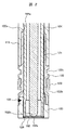
- FIG. 2 is an enlarged cross-sectional view showing a sensor fixing portion of the fuel injection device of FIG.
- the sensor 120 has an end on the proximal end side inserted into the inner periphery on the distal end side of the protective member 122 and is joined to the protective member 122 at a position indicated by reference numeral 125 by welding from the outer peripheral surface side of the protective member 122.
- the sensor 120 is fixed to the protective member 122 by the welded portion 125.
- the joining of the sensor 120 and the protection member 122 by welding can be performed before the sensor 120 and the protection member 122 are assembled to the nozzle 104. Therefore, if the sensor 120 and the protection member 122 are welded in advance before the assembly to the nozzle 104, heat at the time of welding of the welded portion 125 is not input to the nozzle 104.
- the sensor 120 is joined by welding at the position indicated by reference numeral 126 to the outer periphery of the tip of the nozzle 104 along the inner periphery of the end on the tip side.
- the welded portion 126 is for sealing the combustion gas, and is not intended for fixing the sensor 120. Accordingly, the amount of heat input to the welded portion 126 during welding can be reduced compared to welding intended to fix the sensor 120.
- the nozzle 104 has a V-shaped concave portion (groove portion) 104a formed along the circumferential direction on the outer peripheral surface of a cylindrical portion (small diameter portion) 104C.
- a thin wall portion 122 a is formed along the circumferential direction at the base end side end portion of the protection member 122 except for the wiring portion of the sensor signal line 121.
- a plastic deformation portion 122 a provided at the end of the protective member 122 on the proximal end side is bent so as to enter the recess 104 a and is locked to the outer periphery of the nozzle 104.
- the concave portion 104a is not necessarily provided on the entire circumference of the cylindrical portion 104C, and may be provided on a part of the circumferential direction so as to correspond to the thin portion 122a.
- the reduction in strength of the nozzle 104 can be suppressed when the recess 104a is limited to a part of the cylindrical portion 104C in the circumferential direction.
- the recess 104a may be provided on the entire circumference of the cylindrical portion 104C.
- the end portion (thin wall portion) 122a on the proximal end side of the protective member 122 is plastically deformed in the radial direction and the central axis side and accommodated in the recess 104a of the nozzle 104. Thereby, the protection member 122 is fixed to the nozzle 104.
- the material of the protective member 122 is a material that has a yield stress equal to or less than that of the nozzle 104.
- the end 122a of the protection member 122 can be plastically deformed without deforming the nozzle 104.
- the protective member 122 can be fixed to the nozzle 104 without adversely affecting the performance (flow rate performance, oil tightness performance, etc.) of the fuel injection device 100.
- the protective member 122a has a structure in which a part of the outer diameter side of the protective member 122 including the plastically deformed end portion (thin portion) 122a is covered with the resin material of the housing 10. Since the resin material of the housing 10 covers the plastic deformation part formed by the thin part 122a from the outer peripheral surface side, it functions to maintain the plastic deformation state of the thin part 122a.
- the protective member 122 has a seal disposition groove 122b for attaching the seal member 123 and a groove portion 122c used for assembly to the nozzle 104.
- the plastic deformation part (thin wall part) 122 a in the protection member 122 fixes the sensor 120 to the nozzle 104 via the protection member 122 and the welded part 125.
- the plastic deformation portion 122 a is provided at a portion of the sensor 104 on the side of the proximal end portion of the nozzle 104.
- the plastic deformation part 122a is formed by caulking, for example. Further, in the fixing structure of the sensor 120, the welded portion that receives heat with respect to the nozzle 104 is only the portion indicated by reference numeral 126.
- the nozzle 104 that affects the performance (flow rate performance, oil tightness performance, etc.) of the fuel injection device 100 when heat is applied to a portion on the proximal end side of the nozzle 104, particularly a portion closer to the proximal end portion than the sensor 120.
- the deformation is likely to occur. This is because the amount of deviation (eccentricity) from the central axis 100a increases on the tip side of the nozzle 104 when deformation occurs due to heat input to the nozzle 104 portion closer to the base end than the sensor 120. .
- the heat input by welding is not required for the portion of the nozzle 104 closer to the base end than the sensor 120.
- transformation of the nozzle 104 by heat input can be suppressed, and the protection member 122 can be fixed to a nozzle.
- the protective member 122 can be fixed to the nozzle 104 without adversely affecting the performance (flow rate performance, oil tightness performance, etc.) of the fuel injection device 100.
- the welded portion 126 is intended for sealing, and is not intended for fixing the sensor 120. For this reason, the heat input amount in the welded portion 126 can be reduced as described above. In this embodiment, since the amount of heat input by welding is reduced at a place where the influence of heat input on the deformation of the nozzle 104 is small, the deformation of the nozzle 104 can be effectively suppressed.
- the groove 122 d for wiring the sensor signal line 121 is provided in the protection member 122.
- the strength reduction of the nozzle 104 can be suppressed.
- the recess 104 a is formed on the outer peripheral surface of the nozzle 104. For this reason, the strength reduction of the nozzle 104 can be suppressed by reducing the structure that may cause the strength reduction of the nozzle 104.
- the same configuration as the first embodiment and the configuration having the same function as the first embodiment will be described using the same reference numerals as in the first embodiment and different contents from the first embodiment. Therefore, the description of the same contents (configuration / effects) as in the first embodiment is omitted.
- the basic structure of the fuel injection device is the same as that of the first embodiment shown in FIG.
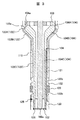
- FIG. 3 is an enlarged cross-sectional view of the sensor fixing part of the fuel injection device for a modified example of the sensor fixing part.
- the plastic deformation portion (thin wall portion) 122a of the protection member 122 is engaged with the enlarged diameter portion (large diameter portion) 104A of the nozzle 104, and the protection member 122 is fixed to the nozzle 104.
- the nozzle 104 is formed with a V-shaped recess (groove) 104a along the circumferential direction on the outer peripheral surface of the enlarged diameter portion 104A.
- the recess 104a of this embodiment is formed in the same manner as in the first embodiment except that the recess 104a is formed on the outer peripheral surface of the enlarged diameter portion 104A.
- the protective member 122 corresponds to the enlarged diameter portion 104A, the reduced diameter portion 104B, and the cylindrical shape portion (small diameter portion) 104C of the nozzle 104, and the enlarged diameter portion 122A, the reduced diameter portion 122B, and the cylindrical shape portion (small diameter portion) 122C. It has the structure which has.
- a thin portion 122a is formed along the circumferential direction at the end of the protective member 122 on the side of the base end portion of the enlarged diameter portion 122A, excluding the wiring portion of the sensor signal line 121.
- the thin-walled portion 122a of the protective member 122 is plastically deformed by the enlarged diameter portion 104A of the nozzle 104 in the same manner as in the first embodiment, and is accommodated in the V-shaped concave portion 104a provided in the nozzle 104. Thereby, the protection member 122 is fixed to the nozzle 104.
- the concave portion 104a which is a fixing portion of the protection member 122, is provided in a portion where there is a limit to increasing the rigidity.
- the enlarged diameter portion 104A of the nozzle 104 can be increased in thickness, and the rigidity can be easily increased.
- the protective member 122 can be fixed at a location where the rigidity of the nozzle 104 is high by providing the fixed portion of the protective member 122 in the enlarged diameter portion 104A. Thereby, the width dimension and depth dimension of the recessed part 104a can be enlarged, and the plastic deformation amount of the thin part (plastic deformation part) 122a can be enlarged. For this reason, the holding strength of the protection member 122 can be improved.
- this invention is not limited to each above-mentioned Example, Various modifications are included.
- the above-described embodiments have been described in detail for easy understanding of the present invention, and are not necessarily limited to those having all the configurations.
- a part of the configuration of one embodiment can be replaced with the configuration of another embodiment, and the configuration of another embodiment can be added to the configuration of one embodiment.
- SYMBOLS 101 Valve body, 102 ... Fixed valve, 102a ... Fuel injection hole, 102b ... Valve seat, 103 ... Guide member, 104 ... Nozzle, 104a ... Recessed part, 104A ... Wide diameter part (large diameter part) of nozzle, 104B ... Nozzle 104C ... Cylinder-shaped part (small diameter part) of the nozzle, 105 ... Mover guide, 106 ... Movable core, 107 ... Fixed core, 108 ... Coil, 109 ... Housing, 110A ... First spring, 110B ... No. 2 springs, 111... Regulator, 112 .. through hole, 112 a .. fuel supply port, 113 a... Terminal connected to coil 108, 113 b .. terminal connected to sensor 120, 114. 121, signal lines, 122, protective members, 122a, thin portions.
Landscapes
- Engineering & Computer Science (AREA)
- Chemical & Material Sciences (AREA)
- Combustion & Propulsion (AREA)
- Mechanical Engineering (AREA)
- General Engineering & Computer Science (AREA)
- Fuel-Injection Apparatus (AREA)
Abstract
本発明の目的は、ノズルの変形を抑制し、燃料噴射装置の性能(流量性能や油密性能等)の低下を抑制することができるセンサの取り付け構造を有する燃料噴射装置を提供することにある。そのため、基端部に設けられた燃料供給口112aと、先端部に設けられた燃料噴射孔102aと、中心軸線100a方向に延設された先端部の側の端部に弁座および燃料噴射孔102aを有するノズル104と、ノズル104の内側で弁座に対して接離可能に設けられた弁体101と、ノズル104の先端部の側の端部の外周に設けられたセンサ120と、センサ120に対して基端部の側であってノズル104の外周側に設けられ、先端部の側の端部にセンサ120が固定された保持部材122と、を備え、保持部材122は基端部の側の端部にノズル104の外周に係止された塑性変形部122aを有する。
Description
本発明は、内燃機関に用いるのに好適な燃料噴射装置に関するものである。
燃焼室内に燃料を直接噴射する直噴式内燃機関において、燃料噴射装置は先端部が燃焼室内に臨むようにシリンダヘッドに配置される。近年の燃費・排気規制の強化に対して燃焼室内の状態を検出するために、燃料噴射装置の先端にセンサを取り付けてセンサを一体化した燃料噴射装置が知られている。このような燃料噴射装置として、国際公開番号WO2012/115036号の公報(特許文献1)に記載された燃料直噴式内燃機関の筒内圧検出装置がある。
この筒内圧検出装置は、燃焼室に燃料を噴射するインジェクタの先端近傍に燃料噴射孔の周囲を囲むリング状の圧力検出素子(筒内圧センサ)を設けている。この筒内圧検出装置では、圧力検出素子がインジェクタに一体に設けられるため、シリンダヘッドや燃焼室の形状・構造を変更する必要がない。また、インジェクタ内を通過する燃料で圧力検出素子を冷却して圧力検出精度及び耐久性を高めることができる。さらに、リング状の圧力検出素子は燃料噴射孔の周囲を囲むため、圧力検出素子が燃料噴射孔から噴射された燃料と干渉するのを回避しながら、圧力検出素子の寸法を最大限に大きくして圧力検出精度を確保することができる(要約参照)。
特許文献1の筒内圧検出装置では、燃料噴射孔を有する弁座部材がバルブハウジングの先端部内周に溶接されている。そしてバルブハウジングの先端部外周には、圧電素子よりなるリング状の圧力検出素子が溶接により固定されている。このとき圧力検出素子は、先端側(燃焼室側)の端部がバルブハウジングの先端部に溶接されている(第1溶接部)。
また、圧力検出素子の基端側(デリバリパイプ側)の端部は、バルブハウジングの外周であって圧力検出素子よりも基端側(デリバリパイプ側)に設けられたカラー構造体の先端側端部に溶接されている(第2溶接部)。そしてカラー構造体はその基端側端部がバルブハウジングの外周に溶接されている(第3溶接部、段落0042-0048及び図3参照)。なお上述した第1溶接部、第2溶接部および第3溶接部は、説明を分かり易くするため、本明細書において定義した名称である。
また、圧力検出素子の基端側(デリバリパイプ側)の端部は、バルブハウジングの外周であって圧力検出素子よりも基端側(デリバリパイプ側)に設けられたカラー構造体の先端側端部に溶接されている(第2溶接部)。そしてカラー構造体はその基端側端部がバルブハウジングの外周に溶接されている(第3溶接部、段落0042-0048及び図3参照)。なお上述した第1溶接部、第2溶接部および第3溶接部は、説明を分かり易くするため、本明細書において定義した名称である。
すなわち特許文献1の筒内圧検出装置では、圧力検出素子は第1溶接部によりバルブハウジングに溶接固定されると共に、第2溶接部およびカラー構造体を介して第3溶接部によりバルブハウジングに溶接固定されている。
特許文献1の筒内圧検出装置では、圧力検出素子(以下、センサという)をインジェクタ(以下、燃料噴射装置という)と一体化する際に、センサと燃料噴射装置とを溶接により接合する構造としている。
特許文献1の構造では、特にセンサよりも基端側に設けられた第3溶接部の溶接による入熱により燃料噴射装置のバルブハウジング(以下、ノズルという)が変形する可能性がある。ノズルの変形は燃料噴射装置の性能(流量性能や油密性能等)に悪影響を及ぼす。
本発明の目的は、ノズルの変形を抑制し、燃料噴射装置の性能(流量性能や油密性能等)の低下を抑制することができるセンサの取り付け構造を有する燃料噴射装置を提供することにある。
上記課題を解決するために、本発明の燃料噴射装置は、
基端部に設けられた燃料供給口と、
前記基端部に対して反対側の端部となる先端部に設けられた燃料噴射孔と、
前記基端部と前記先端部とを結ぶ中心軸線方向に延設された中空の筒状体で構成され、前記先端部の側の端部に弁座および前記燃料噴射孔を有するノズルと、
前記ノズルの内側で前記弁座に対して接離可能に設けられた弁体と、
前記ノズルの前記先端部の側の端部の外周に設けられたセンサと、
前記センサに対して前記基端部の側であって前記ノズルの外周側に設けられ、前記先端部の側の端部に前記センサが固定された保持部材と、を備え、
前記保持部材は、前記基端部の側の端部に前記ノズルの外周に係止された塑性変形部を有する。
基端部に設けられた燃料供給口と、
前記基端部に対して反対側の端部となる先端部に設けられた燃料噴射孔と、
前記基端部と前記先端部とを結ぶ中心軸線方向に延設された中空の筒状体で構成され、前記先端部の側の端部に弁座および前記燃料噴射孔を有するノズルと、
前記ノズルの内側で前記弁座に対して接離可能に設けられた弁体と、
前記ノズルの前記先端部の側の端部の外周に設けられたセンサと、
前記センサに対して前記基端部の側であって前記ノズルの外周側に設けられ、前記先端部の側の端部に前記センサが固定された保持部材と、を備え、
前記保持部材は、前記基端部の側の端部に前記ノズルの外周に係止された塑性変形部を有する。
本発明によれば、燃料噴射装置のノズルへの入熱を抑制することができ、ノズルの変形を抑制してセンサを燃料噴射装置に取り付けることができる。このため、燃料噴射装置の性能への悪影響を抑制して、センサと燃料噴射装置とを一体化することができる。上記した以外の課題、構成及び効果は、以下の実施形態の説明により明らかにされる。
以下、本発明に係る実施例を説明する。
[実施例1]
図1は、本発明が実施される燃料噴射装置の一実施例に係る全体構成を示す断面図である。なお、以降すべての図は説明のため寸法を誇張して示しており、実際の寸法とは異なる。
[実施例1]
図1は、本発明が実施される燃料噴射装置の一実施例に係る全体構成を示す断面図である。なお、以降すべての図は説明のため寸法を誇張して示しており、実際の寸法とは異なる。
燃料噴射装置100は、中心軸線100a方向に貫通する貫通孔112が形成された固定コア107を有し、固定コア107の貫通孔112内にスプリング110Aおよび調整子111が配設されている。
固定コア107の上端部には燃料供給口112aが設けられ、燃料供給口112aに図示しない燃料配管(デリバリパイプ)が連結される。燃料配管には燃料を加圧して供給するための図示しない高圧ポンプが接続され、高圧ポンプにより加圧された燃料が燃料供給口112aを通じて燃料噴射装置100に供給される。一端部が燃料供給口112aを構成する貫通孔112は固定コア107の中心部に燃料通路を構成し、加圧燃料は貫通孔112を通じて燃料噴射装置100の先端部に設けられた燃料噴射孔102aに供給される。
燃料噴射装置100においては、燃料配管が連結される燃料供給口112a側の端部を基端(基端部)とし、基端側の反対側の端部、すなわち燃料噴射孔102aが設けられる側の端部を先端(先端部)とする。燃料噴射装置100を構成する部品において、中心軸線100aに沿う方向における両端部を指定する場合、燃料噴射装置100における「基端」と「先端」とを用いて、燃料噴射装置100の基端側にある端部を「基端側端部」、燃料噴射装置100の先端側にある端部を「先端側端部」として指定する。
固定コア107の燃料供給口112a側とは反対側の端部(先端部の側の端部)には、中心軸線100a方向に中空部104aが形成されたノズル(バルブボディ)104が接続されている。すなわちノズル104は、中心軸線100a方向に延設された中空の筒状体で構成され、先端部の側の端部に弁座102b(図2参照)および燃料噴射孔102aを有する。なお、ノズル104は特許文献1のバルブハウジングに相当する。
ノズル104は基端部の側の端部側に拡径部104Aが設けられ、拡径部(大径部)104Aから先端部の側に向かって縮径する縮径部104Bが設けられている。縮径部104Bの先端側の端部からは固定弁102が設けられる先端部に向かって直径が一定の円筒形状部104Cが設けられている。円筒形状部104Cの直径は拡径部104Aの直径よりも小さく、拡径部(大径部)104Aに対して小径部104Cを構成する。
ノズル104の燃料供給口112a側とは反対側の端部(先端部の側の端部)には、固定弁102が固定されている。固定弁102はノズル104の先端部の側の端部の内周に溶接により固定される。固定弁102には弁座102bが形成されると共に、燃料流れの方向において弁座102bの下流側に燃料噴射孔102aが形成されている。固定弁102は弁座部材と呼ばれる場合もある。
ノズル104の内側の、固定コア107の先端部の側の端面と固定弁102の基端部の側の端面との間の空間(中空部104a)に、弁体101および可動コア106で構成される可動子101,106が収容されている。弁体101はノズル104の内側で弁座102bに対して接離可能に設けられている。
弁体101の基端部の側の端部に設けられた拡径部101aにはスプリング(第1スプリング)110Aの着座面が設けられている。スプリング110Aの弁体101側とは反対側の端部は調整子111に当接している。調整子111は固定コア107に固定されている。これにより、弁体101はスプリング110Aにより閉弁方向に付勢されている。
また調整子111は貫通孔112内で中心軸線100aに沿う方向の位置が調整されることにより、弁体101の付勢力が調整される。
また調整子111は貫通孔112内で中心軸線100aに沿う方向の位置が調整されることにより、弁体101の付勢力が調整される。
弁体101は、ガイド部材103と可動子ガイド105とによって、上下方向に往復運動できるように保持されている。すなわち弁体101は、開閉弁方向の動きを、2つのガイド部材103,105によって案内されている。
ノズル104の中空部104aには可動コア106が設けられている。可動コア106の中央部には、中心軸線100aに沿う方向に貫通する貫通孔106aが形成されており、弁体101が貫通孔106aに挿通され、弁体101と可動コア106とが中心軸線100aに沿う方向に相対運動可能な状態で組み付けられている。
可動コア106の基端部の側の端面は固定コア107と対向し、可動コア106の先端部の側の端面には第2スプリング110Bの基端部の側の端部が当接している。第2スプリング110Bの先端部の側の端部はガイド部材103の基端部の側の端面に当接している。これにより第2スプリング110Bは可動コア106を基端部の側(開弁方向)に向けて付勢する。
第2スプリング110Bにより開弁方向に付勢された可動コア106は、弁体101の拡径部101aに係合し、弁体101に対する相対運動が規制されている。第1スプリング110Aによる閉弁方向の付勢力は第2スプリング110Bによる開弁方向の付勢力よりも大きい。このため、コイル108に通電していない閉弁状態においては、弁体101は第1スプリング110Aの付勢力と第2スプリング110Bの付勢力との差分の付勢力によって閉弁方向に付勢されている。その結果、弁体101はノズル104の先端に設けられた固定弁102の弁座102bと当接し、高圧ポンプから供給された燃料の流れを遮断している。
本実施例では、弁体101と可動コア106とが中心軸線100aに沿う方向に相対運動可能に構成されているが、弁体101と可動コア106とは固定されていてもよい。なお、弁体101と可動コア106とが固定されている場合は、第2スプリング110Bは不要である。
ノズル104の基端部の側の端部の外周には、コイル108が巻回されている。コイル108の外周は樹脂製のハウジング109で覆われている。その結果、コイル108は固定コア107の外周部に配置されており、ハウジング109、ノズル104および可動コア106の部分に、矢印φで示すトロイダル状の磁気通路が形成されている。
コイル108の外周を覆うハウジング109を形成する樹脂は、コネクタ114をハウジング109と一体的に形成している。コネクタ114の内側(プラグ挿入部)には、コイル108に電気的に接続された端子(配線部材)113aの先端部が露出する。端子113aの先端部に、図示しないコントローラからの配線が接続されたプラグ(図示せず)が接続される。これにより、図示しないコントローラにより、端子113aの先端部を通じてコイル108の通電および非通電が制御される。
ここで、弁体101の開閉弁動作について説明しておく。コイル108に通電されると、磁気通路φを通る磁束によって可動コア106と固定コア107との間に磁気吸引力が発生する。可動コア106は固定コア107により吸引されることで基端部の側(開弁方向)へ動き、固定コア107の先端部の側の端面に衝突するまで移動する。
その結果、弁体101が固定弁102の弁座102bから離れて弁体101と弁座102bとの間の燃料通路が開かれた状態(開弁状態)となり、固定コア107の貫通孔112から供給された燃料を燃料噴射孔102aから燃焼室内へ噴射する。
コイル108への通電が断たれると磁気通路φの磁束が消滅し、磁気吸引力も消滅する。この状態では弁体101を閉弁方向に押すスプリング110Aのばね力が弁体101に作用する。その結果、弁体101は固定弁102の弁座102bに接触する閉弁位置に押し戻される。これにより、弁体101と弁座102bとの間の燃料通路は閉じられた状態(閉弁状態)となる。
次に、センサ120の取り付け構造について説明する。
ノズル104の外周先端部にはセンサ素子を有する円環状のセンサ120が配置されており、センサ120からのセンサ信号線121がノズル104およびハウジング109に沿って配置されている。センサ120のセンサ素子は燃焼室の状態に係る物理量を検出する。
センサ信号線121はノズル104の外周側に配置され、樹脂115の内側に配置される。センサ信号線121は樹脂115に埋設され、端部がコネクタ114の内側(プラグ挿入部)に露出する端子(配線部材)113bに接続される。センサ120のセンサ出力は、センサ信号線121および端子113bを通じて外部(例えばコントローラ)に取り出される。
樹脂115は、ノズル104の基端部の側の端部側から先端部の側の端部に向かって途中まで、センサ信号線121の配設範囲の一部を被覆している。ノズル104の先端部の側の端部側では、センサ信号線121は樹脂115によって被覆されていない。樹脂115によって被覆されていないノズル104の先端部の側の端部側では、センサ信号線121の外周側に保護部材122が設けられている。保護部材122はセンサ信号線121を保護するために筒状の形状をしており、センサ信号線121を被覆している。また保護部材122はセンサ120と接合されて一体化されている。保護部材122およびセンサ120で構成される筒状体は中心軸線100aに沿う方向におけるノズル104の中間部から先端までの外周部を覆うように配置されている。
保護部材122はセンサ120に対して基端部の側であってノズル104の外周側に設けられ、先端部の側の端部にセンサ120が固定されている。このように保護部材122はセンサ120を保持する部材であり、保持部材という場合もある。
保護部材122には軸方向に溝122d(図1のA部拡大図参照)を設けた構造となっており、センサ信号線121を配線するためのスペースを確保している。また保護部材122の外周部には周方向に形成されたシール配設溝122bを設け、シール配設溝122bに燃焼ガスをシールするためのシール部材123を配置している。
また、保護部材122よりも基端部の側で保護部材122により保護されていないセンサ信号線121の部分は、上述したように樹脂115により覆われて保護されており、外部には露出しない構造となっている。
センサ120はノズル104の先端部に溶接により接合されており、また保護部材122はノズル104に圧入により組みつけられ、外周部を塑性変形させることによりノズル104に固定している。
保護部材122およびノズル104の固定構造について、図2を用いて説明する。
図2は、図1の燃料噴射装置のセンサ固定部を拡大して示す断面図である。
センサ120は基端部の側の端部が保護部材122の先端部の側の内周に挿入され、保護部材122の外周面側からの溶接により、符号125で示す位置で保護部材122に接合されている。この溶接部125によりセンサ120は保護部材122に固定されている。センサ120と保護部材122との溶接による接合は、センサ120および保護部材122をノズル104に組み付ける前に行うことができる。従って、ノズル104への組み付け前に予めセンサ120と保護部材122との溶接を実施しておけば、溶接部125の溶接時における熱はノズル104には入熱されない。
またセンサ120は、先端部の側の端部の内周に沿って、ノズル104の先端外周に符号126で示す位置で溶接により接合されている。この溶接部126は燃焼ガスをシールするためのもので、センサ120の固定を目的とするものではない。従って、溶接時に溶接部126に入熱される熱量は、センサ120の固定を目的とする溶接に対して少なくすることができる。
ノズル104は、円筒形状部(小径部)104Cの外周面に、周方向に沿ってV字形状の凹部(溝部)104aが形成されている。また保護部材122の基端側端部には、センサ信号線121の配線部を除く部分に、周方向に沿って薄肉部122aが形成されている。保護部材122の基端部の側の端部に設けられた塑性変形部122aは凹部104aに入り込むように曲げられ、ノズル104の外周に係止されている。
凹部104aは円筒形状部104Cの全周に設ける必要はなく、薄肉部122aに対応するように、周方向の一部に設けられればよい。凹部104aは円筒形状部104Cの周方向の一部に限定的に設ける方が、ノズル104の強度低下を抑制することができる。もちろん強度的に問題がなければ、凹部104aは円筒形状部104Cの全周に設けられてもよい。
保護部材122の基端部の側の端部(薄肉部)122aは径方向、中心軸側に塑性変形させてノズル104の凹部104aに収容する。これにより保護部材122はノズル104に固定される。保護部材122に塑性変形部を設けるため、保護部材122の材質はノズル104の材質に対して同等以下の降伏応力となる材質とする。
これにより、ノズル104を変形させることなく、保護部材122の端部122aを塑性変形させることができる。そして、燃料噴射装置100の性能(流量性能や油密性能等)に悪影響を与えることなく、保護部材122をノズル104に固定することが可能となる。
また、保護部材122aは塑性変形させた端部(薄肉部)122aを含む保護部材122の外径側の一部がハウジング10の樹脂材料により覆われた構造となっている。ハウジング10の樹脂材料は薄肉部122aにより形成された塑性変形部を外周面側から覆うため、薄肉部122aの塑性変形状態を維持するように機能する。
なお、保護部材122は、シール部材123を取り付けるシール配設溝122bおよびノズル104に組み付け時に使用する溝部122cを有している。
保護部材122における塑性変形部(薄肉部)122aは、保護部材122及び溶接部125を介して、センサ120をノズル104に固定する。塑性変形部122aはセンサ120に対してノズル104の基端部の側の部分に設けられる。塑性変形部122aは例えばかしめによって形成される。またセンサ120の固定構造において、ノズル104に対して入熱される溶接部は符号126に示す箇所だけである。
ノズル104の基端部の側の部分、特にセンサ120よりも基端部の側の部分に入熱があると、燃料噴射装置100の性能(流量性能や油密性能等)に影響するノズル104の変形が生じ易い。これは、センサ120よりも基端部の側のノズル104部分への入熱により変形が生じた場合、ノズル104の先端側において中心軸線100aからのずれ量(偏芯)が大きくなるためである。
本実施例では、ノズル104のセンサ120よりも基端部の側の部分には、溶接による入熱を必要としない。これにより、入熱によるノズル104の変形を抑制して、保護部材122をノズルに固定することができる。そして、燃料噴射装置100の性能(流量性能や油密性能等)に悪影響を与えることなく、保護部材122をノズル104に固定することが可能となる。
なお本実施例では、溶接部126はシールを目的としたものであり、センサ120の固定を目的にしたものではない。このため溶接部126における入熱量は、上述したように少なくすることができる。本実施例では、ノズル104の変形に対する入熱の影響が小さい箇所で、溶接による入熱量を小さくしているので、ノズル104の変形を効果的に抑制することができる。
また本実施例では、センサ信号線121の配線のための溝122dは、保護部材122に設けられる。このため、溝122dをノズル104の外周面に形成する場合と比べて、ノズル104の強度低下を抑制することができる。本実施例では、ノズル104の外周面に凹部104aを形成している。このため、ノズル104の強度低下を招く可能性のある構造を少なくすることで、ノズル104の強度低下を抑制することができる。
[実施例2]
本発明に係る第二実施例について、図3を用いて説明する。第二実施例において、第一実施例と同じ構成および第一実施例と同じ機能を有する構成については、第一実施例と同じ符号を用い、第一実施例と異なる内容について説明する。従って、第一実施例と同じ内容(構成・作用効果)については、説明を省略する。また、燃料噴射装置の基本構成は、第一実施例の図1と同様である。
[実施例2]
本発明に係る第二実施例について、図3を用いて説明する。第二実施例において、第一実施例と同じ構成および第一実施例と同じ機能を有する構成については、第一実施例と同じ符号を用い、第一実施例と異なる内容について説明する。従って、第一実施例と同じ内容(構成・作用効果)については、説明を省略する。また、燃料噴射装置の基本構成は、第一実施例の図1と同様である。
図3は、センサ固定部の変更例について燃料噴射装置のセンサ固定部を拡大して示す断面図である。
本実施例では、保護部材122における塑性変形部(薄肉部)122aをノズル104の拡径部(大径部)104Aに係合させ、保護部材122をノズル104に固定している。このためにノズル104は、拡径部104Aの外周面に、周方向に沿ってV字形状の凹部(溝部)104aが形成されている。本実施例の凹部104aは、拡径部104Aの外周面に形成さることを除いて、第一実施例と同様に形成される。
また保護部材122は、ノズル104の拡径部104A、縮径部104Bおよび円筒形状部(小径部)104Cに対応して、拡径部122A、縮径部122Bおよび円筒形状部(小径部)122Cを有する構造となっている。
そして保護部材122の拡径部122Aの基端部の側の端部には、センサ信号線121の配線部を除く部分に、周方向に沿って薄肉部122aが形成されている。
そして保護部材122の拡径部122Aの基端部の側の端部には、センサ信号線121の配線部を除く部分に、周方向に沿って薄肉部122aが形成されている。
ノズル104の拡径部104Aで第一実施例と同様に保護部材122の薄肉部122aを塑性変形させることにより、ノズル104に設けたV字形状の凹部104aに収容する。これにより保護部材122はノズル104に固定される。
エンジンヘッドへの取り付けレイアウトの関係から、ノズル104における円筒形状部(小径部)122Cの肉厚を確保することは、困難である。このため第一実施例では、保護部材122の固定部である凹部104aは、剛性を高めることに限界のある部分に設けられていることになる。一方ノズル104の拡径部104Aは、肉厚を厚くすることができ、剛性を高くすることが容易である。本実施例のように、保護部材122の固定部を拡径部104Aに設けることにより、ノズル104の剛性が高い箇所で保護部材122を固定することができる。これにより、凹部104aの幅寸法および深さ寸法を大きくすることができ、薄肉部(塑性変形部)122aの塑性変形量を大きくすることができる。このため、保護部材122の保持強度を向上することができる。
なお、本発明は上記した各実施例に限定されるものではなく、様々な変形例が含まれる。例えば、上記した実施例は本発明を分かりやすく説明するために詳細に説明したものであり、必ずしも全ての構成を備えるものに限定されるものではない。また、ある実施例の構成の一部を他の実施例の構成に置き換えることが可能であり、また、ある実施例の構成に他の実施例の構成を加えることも可能である。また、各実施例の構成の一部について、他の構成の追加・削除・置換をすることが可能である。
101…弁体、102…固定弁、102a…燃料噴射孔、102b…弁座、103…ガイド部材、104…ノズル、104a…凹部、104A…ノズルの拡径部(大径部)、104B…ノズルの縮径部、104C…ノズルの円筒形状部(小径部)、105…可動子ガイド、106…可動コア、107…固定コア、108…コイル、109…ハウジング、110A…第1スプリング、110B…第2スプリング、111…調整子、112…貫通孔、112a…燃料供給口、113a…コイル108に接続された端子、113b…センサ120に接続された端子、114…コネクタ、115…樹脂、120…センサ、121…信号線、122…保護部材、122a…薄肉部。
Claims (5)
- 基端部に設けられた燃料供給口と、
前記基端部に対して反対側の端部となる先端部に設けられた燃料噴射孔と、
前記基端部と前記先端部とを結ぶ中心軸線方向に延設された中空の筒状体で構成され、前記先端部の側の端部に弁座および前記燃料噴射孔を有するノズルと、
前記ノズルの内側で前記弁座に対して接離可能に設けられた弁体と、
前記ノズルの前記先端部の側の端部の外周に設けられたセンサと、
前記センサに対して前記基端部の側であって前記ノズルの外周側に設けられ、前記先端部の側の端部に前記センサが固定された保持部材と、を備え、
前記保持部材は、前記基端部の側の端部に前記ノズルの外周に係止された塑性変形部を有する燃料噴射装置。 - 請求項1に記載の燃料噴射装置において、
前記保持部材の材質の降伏応力は、前記ノズルの材質の降伏応力に対して同じであるか、前記ノズルの材質の降伏応力よりも小さい燃料噴射装置。 - 請求項2に記載の燃料噴射装置において、
前記ノズルは外周面に周方向に形成された凹部を備え、
前記塑性変形部は前記凹部に入り込むように曲げられて前記ノズルの外周に係止されている燃料噴射装置。 - 請求項3に記載の燃料噴射装置において、
前記ノズルは、大径部および小径部を有し、
前記凹部は前記ノズルの前記大径部に形成され、
前記保持部材は、前記ノズルの大径部および小径部に対応する、大径部および小径部を有し、
前記塑性変形部は、前記保持部材の前記大径部に設けられている燃料噴射装置。 - 請求項1に記載の燃料噴射装置において、
前記保持部材の内周に前記中心軸線に沿う方向の溝部を設け、前記溝部に前記センサが出力するセンサ信号の配線を設けた燃料噴射装置。
Priority Applications (1)
| Application Number | Priority Date | Filing Date | Title |
|---|---|---|---|
| JP2018523658A JP6620240B2 (ja) | 2016-06-22 | 2017-06-02 | 燃料噴射装置 |
Applications Claiming Priority (2)
| Application Number | Priority Date | Filing Date | Title |
|---|---|---|---|
| JP2016123784 | 2016-06-22 | ||
| JP2016-123784 | 2016-06-22 |
Publications (1)
| Publication Number | Publication Date |
|---|---|
| WO2017221672A1 true WO2017221672A1 (ja) | 2017-12-28 |
Family
ID=60784452
Family Applications (1)
| Application Number | Title | Priority Date | Filing Date |
|---|---|---|---|
| PCT/JP2017/020600 Ceased WO2017221672A1 (ja) | 2016-06-22 | 2017-06-02 | 燃料噴射装置 |
Country Status (2)
| Country | Link |
|---|---|
| JP (1) | JP6620240B2 (ja) |
| WO (1) | WO2017221672A1 (ja) |
Citations (3)
| Publication number | Priority date | Publication date | Assignee | Title |
|---|---|---|---|---|
| JP2005083289A (ja) * | 2003-09-10 | 2005-03-31 | Hitachi Ltd | 燃料噴射弁 |
| WO2012115036A1 (ja) * | 2011-02-25 | 2012-08-30 | 本田技研工業株式会社 | 燃料直噴式内燃機関の筒内圧検出装置 |
| JP2016133067A (ja) * | 2015-01-20 | 2016-07-25 | 株式会社ケーヒン | 筒内圧センサ付き燃料噴射弁 |
-
2017
- 2017-06-02 JP JP2018523658A patent/JP6620240B2/ja not_active Expired - Fee Related
- 2017-06-02 WO PCT/JP2017/020600 patent/WO2017221672A1/ja not_active Ceased
Patent Citations (3)
| Publication number | Priority date | Publication date | Assignee | Title |
|---|---|---|---|---|
| JP2005083289A (ja) * | 2003-09-10 | 2005-03-31 | Hitachi Ltd | 燃料噴射弁 |
| WO2012115036A1 (ja) * | 2011-02-25 | 2012-08-30 | 本田技研工業株式会社 | 燃料直噴式内燃機関の筒内圧検出装置 |
| JP2016133067A (ja) * | 2015-01-20 | 2016-07-25 | 株式会社ケーヒン | 筒内圧センサ付き燃料噴射弁 |
Also Published As
| Publication number | Publication date |
|---|---|
| JP6620240B2 (ja) | 2019-12-11 |
| JPWO2017221672A1 (ja) | 2018-11-29 |
Similar Documents
| Publication | Publication Date | Title |
|---|---|---|
| CN103380357B (zh) | 燃料直喷式内燃机的筒内压力检测装置 | |
| JP5464167B2 (ja) | 燃料噴射弁 | |
| US10364758B2 (en) | High pressure gas phase injector | |
| US5634597A (en) | Electromagnetically actuated fuel injection valve | |
| KR20110027825A (ko) | 가스 연료용 분사 밸브 | |
| EP2103803B1 (en) | Electromagnetic fuel injection valve | |
| US9068542B2 (en) | Fuel injector | |
| JP2004518066A (ja) | 燃料噴射弁 | |
| JP2002540342A (ja) | 燃料噴射弁 | |
| JP2008163948A (ja) | 内燃機関に用いられる燃料圧送装置 | |
| JP4453745B2 (ja) | 燃料噴射弁 | |
| US11162465B2 (en) | Fuel injection valve | |
| US7063279B2 (en) | Fuel injection valve | |
| JP6620240B2 (ja) | 燃料噴射装置 | |
| JP5857952B2 (ja) | 燃料噴射弁 | |
| US20100263631A1 (en) | Fuel injector | |
| JP7291585B2 (ja) | 燃料噴射弁 | |
| JP4584895B2 (ja) | 電磁式燃料噴射弁 | |
| JPH0141828B2 (ja) | ||
| CN109642527B (zh) | 燃料喷射阀 | |
| US7093779B2 (en) | Fuel injection valve | |
| US11821396B2 (en) | Fuel injector | |
| JPH11512167A (ja) | 燃料噴射弁 | |
| JP6669282B2 (ja) | 燃料噴射装置 | |
| CN110741155B (zh) | 燃料喷射阀 |
Legal Events
| Date | Code | Title | Description |
|---|---|---|---|
| WWE | Wipo information: entry into national phase |
Ref document number: 2018523658 Country of ref document: JP |
|
| 121 | Ep: the epo has been informed by wipo that ep was designated in this application |
Ref document number: 17815141 Country of ref document: EP Kind code of ref document: A1 |
|
| NENP | Non-entry into the national phase |
Ref country code: DE |
|
| 122 | Ep: pct application non-entry in european phase |
Ref document number: 17815141 Country of ref document: EP Kind code of ref document: A1 |