WO2017217679A1 - 전동접이식 도어 시스템 - Google Patents
전동접이식 도어 시스템 Download PDFInfo
- Publication number
- WO2017217679A1 WO2017217679A1 PCT/KR2017/005696 KR2017005696W WO2017217679A1 WO 2017217679 A1 WO2017217679 A1 WO 2017217679A1 KR 2017005696 W KR2017005696 W KR 2017005696W WO 2017217679 A1 WO2017217679 A1 WO 2017217679A1
- Authority
- WO
- WIPO (PCT)
- Prior art keywords
- doors
- guide frame
- door
- unit
- moving
- Prior art date
- Legal status (The legal status is an assumption and is not a legal conclusion. Google has not performed a legal analysis and makes no representation as to the accuracy of the status listed.)
- Ceased
Links
Images




Classifications
-
- E—FIXED CONSTRUCTIONS
- E05—LOCKS; KEYS; WINDOW OR DOOR FITTINGS; SAFES
- E05D—HINGES OR SUSPENSION DEVICES FOR DOORS, WINDOWS OR WINGS
- E05D3/00—Hinges with pins
- E05D3/02—Hinges with pins with one pin
-
- E—FIXED CONSTRUCTIONS
- E05—LOCKS; KEYS; WINDOW OR DOOR FITTINGS; SAFES
- E05D—HINGES OR SUSPENSION DEVICES FOR DOORS, WINDOWS OR WINGS
- E05D15/00—Suspension arrangements for wings
- E05D15/26—Suspension arrangements for wings for folding wings
-
- E—FIXED CONSTRUCTIONS
- E05—LOCKS; KEYS; WINDOW OR DOOR FITTINGS; SAFES
- E05F—DEVICES FOR MOVING WINGS INTO OPEN OR CLOSED POSITION; CHECKS FOR WINGS; WING FITTINGS NOT OTHERWISE PROVIDED FOR, CONCERNED WITH THE FUNCTIONING OF THE WING
- E05F15/00—Power-operated mechanisms for wings
- E05F15/60—Power-operated mechanisms for wings using electrical actuators
- E05F15/603—Power-operated mechanisms for wings using electrical actuators using rotary electromotors
- E05F15/605—Power-operated mechanisms for wings using electrical actuators using rotary electromotors for folding wings
-
- E—FIXED CONSTRUCTIONS
- E06—DOORS, WINDOWS, SHUTTERS, OR ROLLER BLINDS IN GENERAL; LADDERS
- E06B—FIXED OR MOVABLE CLOSURES FOR OPENINGS IN BUILDINGS, VEHICLES, FENCES OR LIKE ENCLOSURES IN GENERAL, e.g. DOORS, WINDOWS, BLINDS, GATES
- E06B3/00—Window sashes, door leaves, or like elements for closing wall or like openings; Layout of fixed or moving closures, e.g. windows in wall or like openings; Features of rigidly-mounted outer frames relating to the mounting of wing frames
- E06B3/32—Arrangements of wings characterised by the manner of movement; Arrangements of movable wings in openings; Features of wings or frames relating solely to the manner of movement of the wing
- E06B3/48—Wings connected at their edges, e.g. foldable wings
Definitions
- the present invention relates to a retractable door system, and more particularly, a technique related to a retractable door system for deploying or folding a retractable door in an electric manner.
- Folding door (Folding Door) is installed so that a plurality of doors are folded to one side of the entrance or deployed to the other side in order to take advantage of the entrance and interior space of the building.
- These folding doors are connected by hinges, and the rollers are installed on the doors themselves to be deployed or folded while moving along the rails.
- Republic of Korea Patent Publication No. 10-1271633 (June 11, 2013) of the prior art relates to a folding door, which moves along a guide rail formed in the receiving member, as a folding door comprising a plurality of door members A roller member allowing the plurality of door members to move along the guide rail; A door hinge configured to hinge the plurality of door members to each other; And a roller hinge connecting the plurality of door members and the roller member, wherein the door hinge includes an outer fixing piece having a groove in the center, an inner fixing piece fitted into the groove, the outer fixing piece and the inner fixing piece.
- It includes an outer hinge tube and the inner hinge tube formed integrally at each of the center of rotation of the convenience, extending in the tangential direction from the outer peripheral surface of the outer hinge tube and the inner hinge tube and then bent at a right angle to the outer fixing piece and the inner Technical features that the fixing piece is formed.
- the above-described technique is cumbersome because the user needs to open the door by pushing a plurality of doors to be folded directly, and the disadvantages of the elderly, women, and children are quickly deteriorated by the weight of the door.
- the doors deployed on the receiving members are spaced apart at regular intervals, and thus, there is a problem that dust or foreign substances are introduced into the gaps without being completely made of soundproofing and windproofing.
- the technical problem to be solved of the present invention is to automatically deploy or fold the folding door, can be folded with a small force by connecting the spring hinge between the door, the door can be deployed or folded manually as well as electric, door In order to provide a folding door system that can be sealed in a row when the deployment.
- An electrically folding door system includes a guide frame having a rail formed therein, a plurality of doors that are deployed or folded while moving along the guide frame, and folded to one outside of the guide frame; A hinge part for connecting the plurality of doors to be folded, a moving part connected to each upper one side of the plurality of doors and moving along the guide frame to support the plurality of doors to rotate, and at one side of the guide frame A driving unit arranged to move the moving unit to deploy or fold the plurality of doors, and an alignment unit installed at one side of the guide frame and pressing and aligning upper side surfaces of the plurality of doors so that the plurality of doors are deployed in a line. do.
- the hinge portion a first fixing part for fixing one side of the first door of the plurality of doors, and a pair of first fixing holes spaced apart from each other at one end of the first fixing part to form a hinge coupling
- a second hinge unit having a second fixing hole, a hinge pin inserted into the first fixing hole and the second fixing hole, and the first fixing hole are wrapped on an outer circumferential surface of the hinge pin, and the first fixing part It is supported on the other end and the second fixing portion may include a coil spring for providing an elastic force so that the first hinge unit and the second hinge unit elastically rotates around the hinge pin.
- the moving unit supports a rotatable support while fixing one of the fixed door of the plurality of doors to one side of the guide frame and a plurality of moving doors of the plurality of doors to be movable along the guide frame. It may include a plurality of sliding rollers.
- the driving unit may include a motor for rotating an output shaft in a forward and reverse direction, a first gear having one end connected to the output shaft of the motor to transmit power, and having a plurality of gear teeth inclined at an angle of 45 ° on an outer circumferential surface thereof; Located in the direction orthogonal to the gear, a plurality of gear teeth inclined at an angle of 45 ⁇ is formed on the outer peripheral surface interlocked with the first gear and one end of the second gear and one end of the plurality of doors is the outermost of the plurality of doors It may be connected to the moving part formed in the starting door located in the other end is mounted to the sprocket and may include a chain for moving the moving forward or retracted as the motor rotates in the forward and reverse directions.
- the alignment unit is formed on one end of the guide frame for detecting the position of the start door located in the outermost of the plurality of doors, and the pressure plate is pivotally coupled to one side of the guide frame downward; Is formed on one side of the guide frame, the actuator for rotating the pressure plate and the outermost door when the control passes through a predetermined point to drive the actuator to control the pressure plate to be deployed in a line by pressing the upper end of the plurality of doors It may include.
- the sliding roller may include a shaft that is screwed on the upper end of the door and the other wheel of the shaft rotatably coupled around the axis of the shaft and is moved along the guide frame.
- the sliding rollers are respectively positioned on the upper outer portion of the plurality of moving doors, the plurality of moving doors can be guided to be folded to one outside of the guide frame while being folded in a zigzag form.
- the support portion is formed on the other end of the coupling pin and the coupling pin axially coupled to the shaft hole formed on the upper side of the fixed door and the fixing plate which is screwed with one side of the guide frame opposite the shaft hole It may include.
- Electric folding door system according to the present invention will have the following effects.
- the spring hinge between the door can be folded with a small force can reduce the power consumption.
- the door can be automatically opened and closed, and when the power is cut off, the door can be manually opened and closed to provide convenience to the user.
- the doors when the doors are deployed, the doors are aligned and sealed to completely prevent soundproofing and windproofing, thereby preventing noise and providing a pleasant environment by preventing the inflow of foreign substances from the outside.
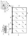
- FIG. 1 is a perspective view of a folding door system according to the present invention
- FIG. 2 is a detailed configuration diagram of the electric folding door system according to FIG.
- FIG. 3 is a front view showing a state in which the doors are closed in the electric folding door system according to FIG.
- Figure 4 is an exemplary view for explaining the configuration of the hinge in the electrically folding door system according to FIG.
- FIG. 5 is a detailed configuration of the drive unit in the electric folding door system according to FIG.
- FIG. 6 is an exemplary view for explaining the operation of the alignment unit in the electrically folding door system according to FIG.
- FIG. 1 is a perspective view of a folding door system according to the present invention
- Figure 2 is a detailed configuration of the folding door system according to Figure 1
- Figure 3 is a state in which the door is closed in the folding door system according to Figure 1
- Figure 4 is an exemplary view for explaining the configuration of the hinge in the folding door system according to Figure 1
- Figure 5 is a detailed configuration of the drive unit in the folding door system according to Figure 1
- Figure 6 Exemplary diagram for explaining the operation of the alignment unit in the folding door system according to.
- the folding door system 100 is installed at the entrance of the building or to partition the space of the room, between the ceiling and the floor and both side walls (not shown) It is formed to be surrounded by.
- the electrically folding door system 100 includes a guide frame 110, a plurality of doors 120, a hinge 130, a moving unit 140, a driving unit 150, and an alignment unit 160.
- the guide frame 110 is installed on the ceiling and the rail 111 is formed inside.
- the rail 111 is provided to be movable a plurality of sliding rollers 142 of the moving unit 140 to be described later.
- both sides of the guide frame 110 is provided with a pair of side frames 10, the bottom may be installed on the bottom frame 20 arranged in parallel with the guide frame 110.
- the plurality of doors 120 includes a fixed door 121 and a plurality of moving doors 122.
- the fixed door 121 is rotatably supported at one side of the guide frame 110.
- the fixed door 121 is rotated while one side is supported by the guide frame 110 by the support part 141 of the moving unit 140 to be described later.
- the fixed door 121 refers to a door that can only rotate without moving in the lateral direction along the guide frame 100.
- the plurality of moving doors 122 of the plurality of doors 120 are installed to be deployed or folded while moving along the guide frame 110.
- a plurality of sliding rollers 142 of the moving unit 140 are coupled to each upper end of the plurality of moving doors 122, and the plurality of moving doors 122 are movable by the sliding rollers 142. Supported.
- the fixed door 121 and the plurality of moving doors 122 are folded in a zigzag form, but folded out of one side of the guide frame 110. Therefore, even if the plurality of moving doors 122 are folded, the indoor space can be maintained.
- the door disposed at the outermost of the plurality of moving doors 122 can be divided into a start door (122-1), the description of the start door 122-1 will be described later.
- the plurality of doors 120 may be formed of a metal material, but is not limited thereto, and may be formed of wood, synthetic resin, or the like.
- the number is not limited.
- the inside of each door can be formed with a pattern of various shapes such that transparent glass is attached to secure a field of view or create aesthetics.
- the hinge portion 130 is a foldable connection of the plurality of doors 120, and includes a first hinge unit 131, a second hinge unit 132, a hinge pin 133, and a coil spring 134. .
- the first hinge unit 131 includes a first fixing part 131-1 and a first fixing hole 131-2.
- the first fixing part 131-1 is fixedly coupled to one side of the first door 120-1 of the plurality of doors 120.
- a pair of the first fixing holes 131-2 are spaced apart from one end of the first fixing part 131-1, and a hole for hinge coupling is formed.
- the second hinge unit 132 includes a second fixing part 132-1 and a second fixing hole 132-2.
- the second fixing part 132-1 opposes the first fixing part 131-1 and fixedly couples the other side of the adjacent second door 120-2.
- the second fixing holes 132-2 are positioned at both ends of the first fixing hole 131-1, respectively, and are formed at one end of the second fixing part 132-2 and are formed as a pair of holes for hinge coupling.
- first door 120-1 and the second door 120-2 are doors for explaining the structure of the hinge portion 130, and the first door 120-1 is a plurality of doors 120. ), And the second door 120-2 is a door adjacent to the first door 120-1.
- the hinge pin 133 is inserted into the first fixing hole 131-2 and the second fixing hole 132-2 to hinge-engage the first hinge unit 131 and the second hinge unit 132. In this case, a center portion of the hinge pin 133 is exposed between the first fixing holes 131-2.
- the coil spring 134 is disposed between the first fixing holes 131-2 and is coupled by the hinge pin 133. At this time, the coil spring 134 is a form wrapped around the outer peripheral surface of the hinge pin 133, where one end of the coil spring 134 is supported by the first fixing portion (131-1), the other end of the second fixing portion ( 132-1).
- the coil spring 134 serves to provide an elastic force so that the first hinge unit 131 and the second hinge unit 132 elastically rotate. That is, when the first door 120-1 and the second door 120-2 are folded, they may be easily folded by the elastic force of the coil spring 134.
- the moving unit 140 is connected to one upper side of each of the plurality of doors 120.
- the moving unit 140 serves to rotatably support the plurality of doors 120 while moving along the guide frame 110.
- the moving part 140 includes a support part 141 and a plurality of sliding rollers 142.
- the support part 141 supports the rotatable door 121 while being fixed to one side of the guide frame 110 among the plurality of doors 120.
- the support part 141 includes a coupling pin 141-1 and a fixing plate 141-2.
- the coupling pin 141-1 is axially coupled to the shaft hole 121-1 formed at one side of the upper end of the fixed door 121 among the plurality of doors 120.
- the fixing plate 141-2 is formed at the other end of the coupling pin 141-1 and is fixed to one side of the guide frame 110 to face the shaft hole 121-1.
- the support 141 may be coupled in the same manner as the lower end of the fixed door 121 so as to stably support the fixed door 121.
- the sliding roller 142 includes a shaft 142-1 and a rolling wheel 142-2.
- the shaft 142-1 has a thread formed at one end thereof and is screwed with one upper side of the plurality of moving doors 122.
- the rolling wheel 142-2 is rotatably coupled around the axis of the shaft 142-1 at the other end of the shaft 142-1.
- the rolling wheel 142-2 is installed to be movable along the rail 111 of the guide frame 110.
- the sliding roller 142 as described above serves to support the plurality of moving doors 122 to be movable along the guide frame 110.
- the moving unit 140 may further include a plurality of lower rollers 143.
- the plurality of lower rollers 143 may be installed such that one side thereof is connected to each lower end of the plurality of moving doors 122 and the other side thereof is movable to the bottom frame 20.
- the driving unit 150 is disposed on one side of the guide frame 110 and serves to expand or fold the plurality of doors 120 by moving the moving unit 140, and the motor 151 and the first gear 152. , A second gear 153 and a chain 154.
- the motor 151 is installed in parallel with the guide frame 110 as a power source of the driving unit 150 and is connected to the output shaft 151-1.
- the motor 151 rotates the output shaft 151-1 in the forward and reverse directions.
- the first gear 152 is connected to the output shaft 151-1 of the motor 151 and serves to transmit power of the motor 151.
- the first gear 151 is formed with a plurality of gear teeth inclined at an angle of 45 degrees on the outer peripheral surface.
- the second gear 153 is positioned in the direction orthogonal to the first gear 152.
- the second gear 153 is formed with a plurality of gear teeth inclined at an angle of 45 degrees on the outer circumferential surface and interlocked with the first gear 152.
- the sprocket 153-1 is formed at one side of the second gear 153, and one end of the chain 154 to be described later is mounted to the sprocket 153-1.
- the chain 154 is disposed in a direction parallel to the guide frame 110 inside the guide frame 110.
- one end of the chain 154 serves to support the outermost starting door 122-1 of the plurality of doors 120 to be movable. That is, one end of the chain 154 is connected to the sliding roller 142 and the other end is mounted to the sprocket 153-1.
- the chain 154 advances or retracts the sliding roller 142 supporting the start door 122-1 when the motor 151 rotates in the forward and reverse directions.
- the start door 122-1 is to explain the configuration of the driving unit 150 as the door located at the outermost side of the plurality of moving doors 122.
- the motor 151, the first gear 152, and the second gear 153 are wrapped by a gear box (not shown) and the chain 154 is movably penetrated.
- the inside includes a plurality of bearings (not shown) and serves to support the output shaft 151-1.
- the alignment unit 160 is installed at one side of the guide frame 110 and serves to press the upper side surfaces of the plurality of doors 120 so that the plurality of doors 120 are aligned in a line.
- the alignment unit 160 includes a detector 161, a pressure plate 162, an actuator 163, and a controller 164.
- the sensing unit 161 is installed at one end of the guide frame 110 to detect the position of the start door 122-1.
- the sensing unit 161 is installed inside one end of the guide frame 110 to detect the position of the sliding roller 142 supporting the opening door 122-1.
- the sensing unit 161 serves to send a signal to the controller 164 to be described later.
- the pressure plate 162 is rotatably installed downward from one side of the guide frame 110. That is, the pressing plate 162 is formed in a plate shape in the longitudinal direction along the longitudinal direction of the guide frame 110 and is coupled to be rotatable downward from the front lower end of the guide frame 110.
- the actuator 163 is installed on one side of the guide frame 110 and rotates the pressure plate 162.
- the actuator 163 is shown to be installed on both sides of the guide frame 110, but is not limited thereto, and the number is not limited if it serves to support the pressing plate 162 rotatably. That is, a plurality may be spaced apart along the longitudinal direction of the guide frame 110.
- the actuator 163 is coupled to the folding member 163-1 such that the pressure plate 162 rotates at the same time and is easily rotated. That is, the folding member 163-1 is hinged two panels, one side is fixed to one side of the pressure plate 162 and the other side is coupled to the actuator 163. The folding member 163-1 rotates the pressure plate 162 downward in accordance with the driving of the actuator 163.
- the controller 164 is installed inside or outside the guide frame 110 and serves to drive the actuator 163. That is, the controller 164 receives the signal from the detector 161 when the outermost opening door 122-1 passes a predetermined point of the detector 161 to drive the actuator 163. In this case, the pressure plate 162 may press the upper ends of the plurality of doors 120 to align the plurality of doors 120 in a row.
- the controller 164 may control the driving of the actuator 150 as well as the driving of the actuator 150. That is, when a user operates a switch or a remote controller (not shown) to expand or collapse the plurality of doors 120 in the guide frame 110, the driving unit 150 moves the moving unit 140 to move the plurality of doors 120. Can be expanded or folded back
- the driving unit 150 receives the signal and rotates the motor 151. Let's do it.
- the first gear 152 and the second gear 153 connected to the output shaft 151-1 of the motor 151 are interlocked and interlocked, and accordingly, the sprocket 153-1 connected to the second gear 153. Is rotated in the same direction as the second gear (153). Then, the chain 154 mounted on the sprocket 153-1 is advanced so that the sliding door 142 supporting the start door 122-1 is advanced.
- the sensing unit 161 sends a signal to the control unit 164.
- the actuator 162 receiving the signal from the sensing unit 161 rotates the pressure plate 163 downward to press the upper ends of the plurality of doors 120.
- the plurality of doors 120 may be arranged in a line in the guide frame 110 to seal the doorway.
- the electric folding door system 100 by tightly sealing the entrance to maintain the heat insulation of the room can save energy, soundproof and windproof is made completely to prevent noise and outside It provides a pleasant environment by preventing the inflow of foreign substances.
- the door can be automatically opened and closed to provide convenience to the user.
Landscapes
- Engineering & Computer Science (AREA)
- Mechanical Engineering (AREA)
- Civil Engineering (AREA)
- Structural Engineering (AREA)
- Extensible Doors And Revolving Doors (AREA)
- Power-Operated Mechanisms For Wings (AREA)
Abstract
본 발명은 전동접이식 도어 시스템 에 관한 것으로, 내측에 레일이 형성되는 가이드 프레임과, 상기 가이드 프레임을 따라 이동하면서 전개되거나 접철되며, 상기 가이드 프레임의 일 외측으로 접철되는 복수의 도어와, 상기 복수의 도어가 접철되도록 연결하는 경첩부와, 상기 복수의 도어의 각 상부 일측에 연결되어 상기 가이드 프레임을 따라 이동하면서 상기 복수의 도어가 회동하도록 지지하는 이동부와, 상기 가이드 프레임의 일측에 배치되어 상기 이동부를 이동시켜 상기 복수의 도어를 전개 또는 접철시키는 구동부 및 상기 가이드 프레임의 일측에 설치되며 상기 복수의 도어가 일렬로 전개되도록 상기 복수의 도어의 상부 측면을 가압하여 정렬시키는 정렬부를 포함한다. 이에 따라, 출입구를 견고하게 밀폐하여 실내의 단열을 유지하므로 에너지를 절약할 수 있으며, 방음 및 방풍이 완벽하게 이루어져 소음을 방지하고 외부의 이물질의 유입을 방지하여 쾌적한 환경을 제공한다
Description
본 발명은 전동접이식 도어 시스템에 관한 것으로, 더욱 상세하게는 접철식으로 설치되는 도어를 전동 방식으로 전개하거나 접철시키는 전동접이식 도어 시스템에 관한 기술이 개시된다.
접이식 도어(Folding Door)는 건물의 출입구나 실내 공간을 가치 있게 활용하고자 다수의 도어가 출입구의 일측으로 접철되거나 타측으로 전개되도록 설치된다. 이러한 접철식 도어는 경첩에 의해 연결되고, 도어 자체에 롤러가 설치되어 레일을 따라 이동하면서 전개되거나 접철된다.
종래의 기술 중 대한민국 등록특허공보 제10-1271633호(2013년06월 11일 공고)는 접이식 도어에 관한 것으로, 수납 부재에 형성된 가이드 레일을 따라 이동하며, 복수의 도어 부재를 포함하는 접이식 도어로서, 상기 복수의 도어 부재가 상기 가이드 레일을 따라 이동 가능하도록 하는 롤러 부재; 상기 복수의 도어 부재를 상호 힌지 결합하는 도어 힌지; 및 상기 복수의 도어 부재와 상기 롤러 부재를 연결하는 롤러 힌지를 포함하고, 상기 도어 힌지는, 중앙에 홈이 형성된 외부 고정편, 상기 홈에 끼워지는 내부 고정편, 상기 외부 고정편 및 상기 내부 고정편의 회동 중심 지점에 각각 일체로 형성된 외부 힌지관 및 내부 힌지관을 포함하되, 상기 외부 힌지관 및 상기 내부 힌지관의 외주면에서 접선 방향으로 연장된 후 직각으로 절곡 연장되어 상기 외부 고정편 및 상기 내부 고정편이 형성되는 것을 기술적 특징으로 한다.
그런데 상기의 기술은 사용자가 다수의 도어를 직접 접히도록 밀면서 개방해야 하므로 이는 번거롭고, 도어의 무게에 의해 노약자나 여성, 어린이는 체력이 금방 저하되는 단점이 있다. 게다가 수납 부재에 전개된 도어들은 일정 간격 벌어져 있어 방음 및 방풍이 완벽하게 이루어 지지 않고 벌어진 틈으로 먼지나 이물질이 유입되는 문제점이 있다.
본 발명의 해결하고자 하는 기술적 과제는 접이식 도어를 자동으로 전개하거나 접철시키며, 도어 간에 스프링 경첩으로 연결하여 적은 힘으로도 접철시킬 수 있으며, 도어를 전동뿐만 아니라 수동으로 전개하거나 접철시킬 수 있으며, 도어를 전개시에는 일렬로 정렬시켜 밀폐할 수 있는 전동접이식 도어 시스템을 제공하기 위함이다.
본 발명의 일 실시예에 따른 전동접이식 도어 시스템은, 내측에 레일이 형성되는 가이드 프레임과, 상기 가이드 프레임을 따라 이동하면서 전개되거나 접철되며, 상기 가이드 프레임의 일 외측으로 접철되는 복수의 도어와, 상기 복수의 도어가 접철되도록 연결하는 경첩부와, 상기 복수의 도어의 각 상부 일측에 연결되어 상기 가이드 프레임을 따라 이동하면서 상기 복수의 도어가 회동하도록 지지하는 이동부와, 상기 가이드 프레임의 일측에 배치되어 상기 이동부를 이동시켜 상기 복수의 도어를 전개 또는 접철시키는 구동부 및 상기 가이드 프레임의 일측에 설치되며 상기 복수의 도어가 일렬로 전개되도록 상기 복수의 도어의 상부 측면을 가압하여 정렬시키는 정렬부를 포함한다.
또한, 상기 경첩부는, 상기 복수의 도어 중 제1도어의 일측을 고정결합하는 제1고정부와, 상기 제1고정부의 일단에서 서로 이격되며 힌지 결합을 위해 한 쌍의 제1 고정홀이 형성되는 제1경첩유닛과, 상기 제1고정부에 대향하며 인접하는 제2도어의 타측을 고정결합하는 제2고정부와, 상기 제1고정홀의 양단부에 각각 위치하여 힌지 결합을 위해 한 쌍의 제2고정홀이 형성되는 제2경첩유닛과, 상기 제1고정홀과 제2고정홀에 삽입되는 힌지핀 및 상기 제1고정홀 사이에서 상기 힌지핀의 외주면에 감싸지며 일단이 상기 제1고정부에 지지되고 타단이 상기 제2고정부에 지지되어 상기 제1경첩유닛과 제2경첩유닛이 상기 힌지핀을 중심으로 탄성 회전하도록 탄성력을 제공하는 코일스프링을 포함할 수 있다.
또한, 상기 이동부는 상기 복수의 도어 중 하나의 고정 도어를 상기 가이드 프레임의 일측에 고정하면서 회동 가능하게 지지하는 지지부 및 상기 복수의 도어 중 복수의 이동 도어가 상기 가이드 프레임을 따라 이동 가능하도록 지지하는 복수의 슬라이딩 롤러를 포함할 수 있다.
또한, 상기 구동부는 출력축을 정역방향으로 회전시키는 모터와 일단이 상기 모터의 상기 출력축에 연결되어 동력을 전달하며 외주면에 45˚각도로 경사진 복수의 기어치가 형성되는 제1기어와, 상기 제1기어와 직교하는 방향으로 위치하며, 외주면에 45˚각도로 경사진 복수의 기어치가 형성되어 상기 제1기어와 치합 연동되며 일단에 스프로킷이 형성되는 제2기어 및 일단이 상기 복수의 도어 중 최외곽에 위치하는 개시 도어에 형성된 상기 이동부와 연결되고, 타단이 상기 스프로킷에 장착되어 상기 모터가 정역방향으로 회전함에 따라 상기 이동부를 전진 또는 후퇴시키는 체인을 포함할 수 있다.
또한, 상기 정렬부는 상기 가이드 프레임의 일단에 형성되어 상기 복수의 도어 중 최외곽에 위치하는 개시 도어의 위치를 감지하는 감지부와, 상기 가이드 프레임의 일측에 하방으로 회동 가능하게 결합되는 가압판과, 가이드 프레임의 일측에 형성되어, 상기 가압판을 회동시키는 액추에이터 및 상기 최외곽 도어가 기 설정된 지점을 통과하면 상기 액추에이터를 구동시켜 상기 가압판이 상기 복수의 도어의 상단을 가압하여 일렬로 전개되도록 제어하는 제어부를 포함할 수 있다.
또한, 상기 슬라이딩 롤러는 상기 도어들의 상단 일측에서 나사 고정되는 샤프트 및 상기 샤프트의 타단에서 상기 샤프트의 축을 중심으로 회전 가능하게 결합되며 상기 가이드 프레임을 따라 이동되는 구름바퀴를 포함할 수 있다.
또한, 상기 슬라이딩 롤러는 상기 복수의 이동 도어의 상단 외곽부에 각각 위치하되, 상기 복수의 이동 도어가 지그재그 형태로 접철되면서 상기 가이드 프레임의 일 외측으로 접철되도록 안내할 수 있다.
또한, 상기 지지부는 상기 고정 도어의 상단 일측에 형성된 축공에 축회전 가능하게 결합되는 결합핀 및 상기 결합핀의 타단에 형성되며 상기 축공에 대향하여 상기 가이드 프레임의 일측면과 나사 결합되는 고정플레이트를 포함할 수 있다.
본 발명에 따른 전동접이식 도어 시스템은 다음과 같은 효과를 가지게 된다.
첫째, 출입구를 견고하게 밀폐하여 실내의 단열을 유지하므로 에너지를 절약할 수 있다.
둘째, 도어 간에 스프링 경첩으로 연결하여 적은 힘으로도 접철시킬 수 있어 전력 소비를 줄일 수 있다.
셋째, 자동으로 도어를 개방 및 폐쇄할 수 있으며, 전원이 차단시 수동으로 개방 및 폐쇄할 수 있어 사용자에게 편리함을 제공할 수 있다.
넷째, 도어를 전개시에는 일렬로 정렬시켜 밀폐하여 방음 및 방풍이 완벽하게 이루어져 소음을 방지하고 외부의 이물질의 유입을 방지하여 쾌적한 환경을 제공할 수 있다.
도 1은 본 발명에 따른 전동접이식 도어 시스템의 사시도,
도 2는 도 1에 따른 전동접이식 도어 시스템의 세부 구성도,
도 3은 도 1에 따른 전동접이식 도어 시스템에서 도어들이 닫혀있는 상태를 나타낸 정면도,
도 4는 도 1에 따른 전동접이식 도어 시스템에서 경첩의 구성을 설명하기 위한 예시도,
도 5는 도 1에 따른 전동접이식 도어 시스템에서 구동부이 세부 구성도,
도 6은 도 1에 따른 전동접이식 도어 시스템에서 정렬부의 동작을 설명하기 위한 예시도이다.
이하, 첨부된 도면들을 참조하여 본 발명의 실시예를 상세하게 설명한다. 사용되는 용어들은 실시예에서의 기능을 고려하여 선택된 용어들로서, 그 용어의 의미는 사용자, 운용자의 의도 또는 판례 등에 따라 달라질 수 있다. 그러므로 후술하는 실시예들에서 사용된 용어의 의미는, 본 명세서에 구체적으로 정의된 경우에는 그 정의에 따르며, 구체적인 정의가 없는 경우는 당업자들이 일반적으로 인식하는 의미로 해석되어야 할 것이다.
도 1은 본 발명에 따른 전동접이식 도어 시스템의 사시도이고, 도 2는 도 1에 따른 전동접이식 도어 시스템의 세부 구성도이며, 도 3은 도 1에 따른 전동접이식 도어 시스템에서 도어들이 닫혀있는 상태를 나타낸 정면도이고, 도 4는 도 1에 따른 전동접이식 도어 시스템에서 경첩의 구성을 설명하기 위한 예시도이고, 도 5는 도 1에 따른 전동접이식 도어 시스템에서 구동부이 세부 구성도이고, 도 6은 도 1에 따른 전동접이식 도어 시스템에서 정렬부의 동작을 설명하기 위한 예시도이다.
도 1 내지 도 6을 참조하면, 본 발명에 따른 전동접이식 도어 시스템(100)은 건물의 출입구에 설치되거나 또는 실내의 공간을 구획하기 위해 설치되는 것으로서, 천장과 바닥 및 양 측벽(미도시) 사이에서 둘러싸여 지도록 형성된다. 전동접이식 도어 시스템(100)은 가이드 프레임(110)과 복수의 도어(120), 경첩부(130), 이동부(140), 구동부(150) 및 정렬부(160)를 포함한다.
가이드 프레임(110)은 천장에 설치되며 내측에 레일(111)이 형성된다. 레일(111)에는 후술할 이동부(140)의 복수의 슬라이딩 롤러(142)가 이동 가능하도록 설치된다.
한편, 가이드 프레임(110)의 양측에는 한쌍의 측면프레임(10)이 구비되며, 바닥에는 가이드 프레임(110)과 나란한 방향으로 배치되는 바닥프레임(20)이 설치될 수 있다.
복수의 도어(120)는 고정 도어(121)와 복수의 이동 도어(122)를 포함한다. 고정 도어(121)는 가이드 프레임(110)의 일측에서 회동가능하게 지지된다. 이러한, 고정 도어(121)는 후술할 이동부(140)의 지지부(141)에 의해 일측이 가이드 프레임(110)에 지지되면서 회동된다. 고정 도어(121)는 복수의 이동 도어(122)와 달리 가이드 프레임(100)을 따라 횡방향으로 이동하지 않고, 회동만 가능한 도어를 의미한다.
복수의 도어(120) 중 복수의 이동 도어(122)는 가이드 프레임(110)을 따라 이동하면서 전개되거나 접철되도록 설치된다. 이때, 복수의 이동 도어(122)의 각 상단에는 이동부(140)의 복수의 슬라이딩 롤러(142)가 각각 결합되며, 이러한 복수의 이동 도어(122)는 슬라이딩 롤러(142)에 의해 이동 가능하게 지지된다. 상술한, 고정 도어(121)와 복수의 이동 도어(122)는 지그재그 형태로 접철되되, 가이드 프레임(110)의 일 외측으로 접철된다. 따라서, 복수의 이동 도어(122)가 접철되어도 실내 공간을 유지할 수 있다.
한편, 복수의 이동 도어(122) 중 최외곽에 배치된 도어는 개시 도어(122-1)로 구분할 수 있으며 개시 도어(122-1)에 대한 설명은 후술하기로 한다.
이와 같은, 복수의 도어(120)는 금속재로 형성될 수 있으나 이에 한정 되는 것은 아니며 목재나, 합성수지재 등으로 형성될 수 있다. 더욱이, 도면에서는 복수의 도어(120)를 6개로 구비하여 예시하였으나 그 개수가 한정되는 것은 아니다. 게다가, 각 도어의 내측에는 시야를 확보하도록 투명의 유리가 부착되거나 또는 미감을 일으키도록 다양한 모양의 무늬를 형성할 수 있다.
경첩부(130)는 복수의 도어(120)를 접철가능하도록 연결하는 것으로서, 제1경첩유닛(131), 제2경첩유닛(132), 힌지핀(133) 및 코일스프링(134)을 포함한다.
제1경첩유닛(131)은 제1고정부(131-1)와 제1고정홀(131-2)을 포함한다. 제1고정부(131-1)는 복수의 도어(120) 중 제1도어(120-1)의 일측을 고정결합한다. 제1고정홀(131-2)은 제1고정부(131-1)의 일단에서 한쌍이 이격되며 힌지 결합을 위한 홀이 형성된다. 제2경첩유닛(132)은 제2고정부(132-1)와 제2고정홀(132-2)을 포함한다. 제2고정부(132-1)는 제1고정부(131-1)에 대향하며 인접하는 제2도어(120-2)의 타측을 고정결합한다. 제2고정홀(132-2)은 제1고정홀(131-1)의 양단부에서 각각 위치하며 제2고정부(132-2)의 일단에 형성되고 힌지 결합을 위해 한 쌍의 홀로 형성된다.
한편, 제1도어(120-1) 및 제2도어(120-2)는 경첩부(130)의 구성을 설명하기 위해 예시하는 도어로써, 제1도어(120-1)는 복수의 도어(120) 중 어느 하나의 도어이고, 제2도어(120-2)는 제1도어(120-1)와 인접하는 도어이다.
힌지핀(133)은 제1경첩유닛(131)과 제2경첩유닛(132)을 힌지결합하도록 제1고정홀(131-2)과 제2고정홀(132-2)에 삽입된다. 이 경우, 힌지핀(133)의 가운데 부분은 제1고정홀(131-2) 사이에서 노출된다.
코일스프링(134)은 제1고정홀(131-2) 사이에 배치되며 힌지핀(133)에 의해 결합된다. 이때, 코일스프링(134)은 힌지핀(133)의 외주면에 감싸진 형태가 되며 여기서 코일스프링(134)은 일단이 제1고정부(131-1)에 지지되고, 타단이 제2고정부(132-1)에 지지된다. 이러한 코일스프링(134)은 제1경첩유닛(131)과 제2경첩유닛(132)이 탄성 회전하도록 탄성력을 제공하는 역할을 한다. 즉, 제1도어(120-1)와 제2도어(120-2)가 접철되는 경우 코일스프링(134)의 탄성력에 의해 용이하게 접철될 수 있다.
이동부(140)는 복수의 도어(120)의 각 상부 일측에 연결된다. 이동부(140)는 가이드 프레임(110)을 따라 이동하면서 복수의 도어(120)를 회동가능하게 지지하는 역할을 한다. 이동부(140)는 지지부(141) 및 복수의 슬라이딩 롤러(142)를 포함한다. 지지부(141)는 복수의 도어(120) 중 고정 도어(121)를 가이드 프레임(110)의 일측에 고정하면서 회동 가능하게 지지하는 역할을 한다.
지지부(141)는 결합핀(141-1)과 고정플레이트(141-2)를 포함한다. 결합핀(141-1)은 복수의 도어(120) 중 고정 도어(121)의 상단 일측에 형성된 축공(121-1)에 축회전 가능하게 결합된다. 고정플레이트(141-2)는 결합핀(141-1)의 타단에 형성되며 축공(121-1)에 대향하여 가이드 프레임(110)의 일측면과 나사 고정된다. 이와 같은 지지부(141)는 고정 도어(121)를 안정적으로 지지할 수 있도록 고정 도어(121)의 하단과 동일한 방식으로(미도시) 결합될 수 있다.
슬라이딩 롤러(142) 샤프트(142-1) 및 구름바퀴(142-2)를 포함한다. 샤프트(142-1)는 일단에 나사산이 형성되며 복수의 이동 도어들(122)의 상단 일측과 나사결합된다. 구름바퀴(142-2)는 샤프트(142-1)의 타단에서 샤프트(142-1)의 축을 중심으로 회전가능하게 결합된다. 구름바퀴(142-2)는 가이드 프레임(110)의 레일(111) 따라 이동가능하게 설치된다. 이와 같은 슬라이딩 롤러(142)는 복수의 이동 도어(122)를 가이드 프레임(110)을 따라 이동 가능하도록 지지하는 역할을 한다.
한편, 도 2를 참조하면 이동부(140)는 복수의 하부롤러(143)를 더 포함할 수 있다. 복수의 하부롤러(143)는 일측이 복수의 이동 도어(122)의 각 하단과 연결되고 타측은 바닥프레임(20)에 이동가능하도록 설치될 수 있다.
구동부(150)는 가이드 프레임(110)의 일측에 배치되며 이동부(140)를 이동시켜 복수의 도어(120)를 전개하거나 접철시키는 역할을 하는 것으로서, 모터(151), 제1기어(152), 제2기어(153) 및 체인(154)을 포함한다.
모터(151)는 구동부(150)의 동력원으로서 가이드 프레임(110)과 나란한 ?항으로 설치되며 출력축(151-1)이 연결된다. 모터(151)는 출력축(151-1)을 정역방향으로 회전시킨다. 제1기어(152)는 모터(151)의 출력축(151-1)에 연결되며 모터(151)의 동력을 전달하는 역할을 한다. 제1기어(151)는 외주면에 45˚각도로 경사진 복수의 기어치가 형성된다. 제2기어(153)는 제1기어(152)와 직교하는 방향으로 위치된다. 제2기어(153)는 외주면에 45˚각도로 경사진 복수의 기어치가 형성되며 제1기어(152)와 치합되어 연동된다. 제2기어(153)의 일측에는 스프로킷(153-1)이 형성되며 스프로킷(153-1)에는 후술할 체인(154)의 일단이 장착된다.
체인(154)은 가이드 프레임(110)의 내측에서 가이드 프레임(110)과 나란한 방향으로 배치된다. 여기서 체인(154)의 일단은 복수의 도어(120) 중 최 외곽의 개시 도어(122-1)를 이동 가능하게 지지하는 역할을 한다. 즉, 체인(154)의 일단은 슬라이딩 롤러(142)와 연결되고 타단은 스프로킷(153-1)에 장착된다.
이와 같은 체인(154)은 모터(151)가 정역방향으로 회전시 개시 도어(122-1)를 지지하는 슬라이딩 롤러(142)를 전진 또는 후퇴 시킨다. 여기서, 개시 도어(122-1)는 복수의 이동 도어(122) 중 최외곽에 위치한 도어로서 구동부(150)의 구성을 설명하기 위함이다.
이와 같은 구성에서 모터(151)와 제1기어(152) 및 제2기어(153)는 기어박스(도시하지 않음)에 의해 감싸지며 체인(154)이 이동 가능하게 관통된다. 아울러 내부에는 복수의 베어링(도시하지 않음)을 포함하며 출력축(151-1)을 지지하는 역할을 한다.
정렬부(160)는 가이드 프레임(110)의 일측에 설치되며 복수의 도어(120)가 일렬로 정렬되도록 복수의 도어(120)의 상부 측면을 가압하는 역할을 한다. 정렬부(160)는 감지부(161), 가압판(162), 액추에이터(163) 및 제어부(164)를 포함한다.
감지부(161)는 개시 도어(122-1)의 위치를 감지하도록 가이드 프레임(110)의 일단에 설치된다. 부연하면, 감지부(161)는 가이드 프레임(110)의 일단 내측에 설치되어 개시 도어(122-1)를 지지는 슬라이딩 롤러(142)의 위치를 감지한다. 이 경우, 슬라이딩 롤러(142)가 감지부(161)의 기 설정된 지점을 통과하면 감지부(161)는 후술할 제어부(164)에 신호를 보내는 역할을 한다.
가압판(162)은 가이드 프레임(110)의 일측에서 하방으로 회동 가능하게 설치된다. 즉, 가압판(162)은 플레이트 형상으로 가이드 프레임(110)의 길이방향을 따라 장방향으로 형성되며 가이드 프레임(110)의 전면 하단에서 하부로 회동가능하도록 결합된다.
액추에이터(163)는 가이드 프레임(110)의 일측에 설치되며 가압판(162)을 회동시킨다. 한편, 액추에이터(163)는 가이드 프레임(110)의 양측에 설치되도록 도시하였으나 이에 한정되는 것은 아니며 가압판(162)을 회동가능하게 지지하는 역할을 한다면 그 개수가 한정되는 것은 아니다. 즉, 가이드 프레임(110)의 길이방향을 따라 복수개가 이격되어 설치될 수 있다.
또한, 액추에이터(163)에는 가압판(162)이 회동시 안정성을 갖으며 동시에 용이하게 회동하도록 접철부재(163-1)가 결합된다. 즉, 접철부재(163-1)는 2개의 패널이 힌지 결합되며 일측이 가압판(162)의 일측면에 고정되고 타측이 액추에이터(163)에 결합된다. 이러한 접철부재(163-1)는 액추에이터(163)의 구동에 따라 가압판(162)을 하방으로 회동시킨다.
제어부(164)는 가이드 프레임(110)의 내측 또는 외측에 설치되며 액추에이터(163)를 구동시키는 역할을 한다. 즉, 제어부(164)는 최외곽의 개시 도어(122-1)가 감지부(161)의 기 설정된 지점을 통과하면 감지부(161)의 신호를 전달받아 액추에이터(163)를 구동시킨다. 이 경우, 가압판(162)은 복수의 도어(120)의 상단을 가압하여 복수의 도어(120)를 일렬로 정렬시킬 수 있다.
한편, 제어부(164)는 액추에이터(163)의 구동뿐만 아니라, 구동부(150)의 구동을 제어할 수 있다. 즉, 사용자가 복수의 도어(120)를 가이드 프레임(110)에서 전개하거나 접철되도록 스위치나 리모콘(미도시)을 조작하면 구동부(150)는 이동부(140)를 이동시켜 복수의 도어(120)를 전개하거나 반대로 접철시킬 수 있다
이하, 상술한 바와 같이 구성된 본 실시예에 따른 전동접이식 도어 시스템(100)의 작동순서를 설명한다.
도 1 내지 도 6을 참조하여 설명하면, 사용자가 스위치나 리모콘 (미도시)을 이용하여 복수의 도어(120)들이 전개되도록 조작하면 구동부(150)는 그 신호를 전달받아 모터(151)를 회전시킨다.
이때, 모터(151)의 출력축(151-1)에 연결된 제1기어(152) 및 제2기어(153)는 치합하여 연동되고 이에 따라, 제2기어(153)에 연결된 스프로킷(153-1)은 제2기어(153)와 동일한 방향으로 회전하게 된다. 그러면 스프로킷(153-1)에 장착된 체인(154)은 전진하게 되어 개시 도어(122-1)를 지지하는 슬라이딩 도어(142)는 전진된다.
개시 도어(122-1)를 지지하는 슬라이딩 도어(142)가 가이드 프레임(110)의 일측에 설치된 감지부(161)의 기 설정된 지점을 통과하면 감지부(161)는 제어부(164)에 신호를 전달한다. 이 경우, 감지부(161)의 신호를 전달받은 액추에이터(162)는 가압판(163)을 하부로 회동시켜 복수의 도어(120)의 상단을 가압한다. 이 경우, 복수의 도어(120)는 가이드 프레임(110)에서 일렬로 전개되도록 정렬시켜 출입구를 밀폐할 수 있다.
상기한 바와 같이, 본 발명에 따른 전동접이식 도어 시스템(100)은, 출입구를 견고하게 밀폐하여 실내의 단열을 유지하므로 에너지를 절약할 수 있으며, 방음 및 방풍이 완벽하게 이루어져 소음을 방지하고 외부의 이물질의 유입을 방지하여 쾌적한 환경을 제공한다. 또한, 자동으로 도어의 개방 및 폐쇄할 수 있어 사용자에게 편리함을 제공한다.
이상에서 본 발명은 도면을 참조하면서 기술되는 바람직한 실시예를 중심으로 설명되었지만 이에 한정되는 것은 아니다. 따라서 본 발명은 기재된 실시예로부터 도출 가능한 자명한 변형예를 포괄하도록 의도된 특허등록청구범위의 기재에 의해 해석되어져야 한다.
Claims (8)
- 내측에 레일(111)이 형성되는 가이드 프레임(110);상기 가이드 프레임(110)을 따라 이동하면서 전개되거나 접철되며, 상기 가이드 프레임(110)의 일 외측으로 접철되는 복수의 도어(120);상기 복수의 도어(120)가 접철되도록 연결하는 경첩부(130);상기 복수의 도어(120)의 각 상부 일측에 연결되어 상기 가이드 프레임(110)을 따라 이동하면서 상기 복수의 도어(120)가 회동하도록 지지하는 이동부(140);상기 가이드 프레임(110)의 일측에 배치되어 상기 이동부(140)를 이동시켜 상기 복수의 도어(120)를 전개 또는 접철시키는 구동부(150); 및상기 가이드 프레임(110)의 일측에 설치되며 상기 복수의 도어(120)가 일렬로 전개되도록 상기 복수의 도어(120)의 상부 측면을 가압하여 정렬시키는 정렬부(160)를 포함하는 전동접이식 도어 시스템.
- 제1항에 있어서,상기 경첩부(130)는,상기 복수의 도어(120) 중 제1도어(120-1)의 일측을 고정결합하는 제1고정부(131-1)와, 상기 제1고정부(131-1)의 일단에서 서로 이격되며 힌지 결합을 위해 한 쌍의 제1 고정홀(131-2)이 형성되는 제1경첩유닛(131);상기 제1고정부(131-1)에 대향하며 인접하는 제2도어(120-2)의 타측을 고정결합하는 제2고정부(132-1)와, 상기 제1고정홀(131-2)의 양단부에 각각 위치하여 힌지 결합을 위해 한 쌍의 제2고정홀(132-2)이 형성되는 제2경첩유닛(132);상기 제1고정홀(131-2)과 제2고정홀(132-2)에 삽입되는 힌지핀(133); 및상기 제1고정홀(131-2) 사이에서 상기 힌지핀(133)의 외주면에 감싸지며 일단이 상기 제1고정부(131-1)에 지지되고 타단이 상기 제2고정부(132-1)에 지지되어 상기 제1경첩유닛(131)과 제2경첩유닛(132)이 상기 힌지핀(133)을 중심으로 탄성 회전하도록 탄성력을 제공하는 코일스프링(134)을 포함하는 전동접이식 도어 시스템.
- 제1항에 있어서,상기 이동부(140)는,상기 복수의 도어(120) 중 하나의 고정 도어(121)를 상기 가이드 프레임(110)의 일측에 고정하면서 회동 가능하게 지지하는 지지부(141); 및상기 복수의 도어(120) 중 복수의 이동 도어(122)가 상기 가이드 프레임(110)을 따라 이동 가능하도록 지지하는 복수의 슬라이딩 롤러(142)를 포함하는 전동접이식 도어 시스템.
- 제1항에 있어서,상기 구동부(150)는,출력축(151-1)을 정역방향으로 회전시키는 모터(151);일단이 상기 모터(151)의 상기 출력축(151-1)에 연결되어 동력을 전달하며 외주면에 45˚각도로 경사진 복수의 기어치가 형성되는 제1기어(152);상기 제1기어(152)와 직교하는 방향으로 위치하며, 외주면에 45˚각도로 경사진 복수의 기어치가 형성되어 상기 제1기어(152)와 치합 연동되며 일단에 스프로킷(153-1)이 형성되는 제2기어(153); 및일단이 상기 복수의 도어(120) 중 최외곽에 위치하는 개시 도어(122-1)에 형성된 상기 이동부(140)와 연결되고, 타단이 상기 스프로킷(153-1)에 장착되어 상기 모터(151)가 정역방향으로 회전함에 따라 상기 이동부(140)를 전진 또는 후퇴시키는 체인(154)을 포함하는 전동접이식 도어 시스템.
- 제1항에 있어서,상기 정렬부(160)는,상기 가이드 프레임(110)의 일단에 형성되어 상기 복수의 도어(120) 중 최외곽에 위치하는 개시 도어(122-1)의 위치를 감지하는 감지부(161);상기 가이드 프레임(110)의 일측에 하방으로 회동 가능하게 결합되는 가압판(162);가이드 프레임(110)의 일측에 형성되어, 상기 가압판(162)을 회동시키는 액추에이터(163); 및상기 최외곽 도어(122-1)가 기 설정된 지점을 통과하면 상기 액추에이터(163)를 구동시켜 상기 가압판(162)이 상기 복수의 도어(120)의 상단을 가압하여 일렬로 전개되도록 제어하는 제어부(164)를 포함하는 전동접이식 도어 시스템.
- 제3항에 있어서,상기 슬라이딩 롤러(142)는,상기 도어들(120)의 상단 일측에서 나사 고정되는 샤프트(142-1); 및상기 샤프트(142-1)의 타단에서 상기 샤프트(142-1)의 축을 중심으로 회전 가능하게 결합되며 상기 가이드 프레임(110)을 따라 이동되는 구름바퀴(142-2)를 포함하는 전동접이식 도어 시스템.
- 제3항에 있어서,상기 슬라이딩 롤러(142)는,상기 복수의 이동 도어(122)의 상단 외곽부에 각각 위치하되, 상기 복수의 이동 도어(122)가 지그재그 형태로 접철되면서 상기 가이드 프레임(110)의 일 외측으로 접철되도록 안내하는 전동접이식 도어 시스템.
- 제3항에 있어서,상기 지지부(141)는,상기 고정 도어(121)의 상단 일측에 형성된 축공(121-1)에 축회전 가능하게 결합되는 결합핀(141-1); 및상기 결합핀(141-1)의 타단에 형성되며 상기 축공(121-1)에 대향하여 상기 가이드 프레임(110)의 일측면과 나사 결합되는 고정플레이트(141-2)를 포함하는 전동접이식 도어 시스템.
Applications Claiming Priority (2)
| Application Number | Priority Date | Filing Date | Title |
|---|---|---|---|
| KR10-2016-0075101 | 2016-06-16 | ||
| KR1020160075101A KR101730612B1 (ko) | 2016-06-16 | 2016-06-16 | 전동접이식 도어 시스템 |
Publications (1)
| Publication Number | Publication Date |
|---|---|
| WO2017217679A1 true WO2017217679A1 (ko) | 2017-12-21 |
Family
ID=58704915
Family Applications (1)
| Application Number | Title | Priority Date | Filing Date |
|---|---|---|---|
| PCT/KR2017/005696 Ceased WO2017217679A1 (ko) | 2016-06-16 | 2017-05-31 | 전동접이식 도어 시스템 |
Country Status (2)
| Country | Link |
|---|---|
| KR (1) | KR101730612B1 (ko) |
| WO (1) | WO2017217679A1 (ko) |
Cited By (4)
| Publication number | Priority date | Publication date | Assignee | Title |
|---|---|---|---|---|
| CN108691497A (zh) * | 2018-07-12 | 2018-10-23 | 安徽省金鹏节能科技有限公司 | 一种配重式底梁的遮阳窗结构 |
| CN113503116A (zh) * | 2021-05-28 | 2021-10-15 | 杜天宇 | 一种可电动切换的屋顶阳光房构造 |
| TWI866743B (zh) * | 2024-01-15 | 2024-12-11 | 王威詔 | 摺疊式屏幕門 |
| US12584338B2 (en) | 2024-06-06 | 2026-03-24 | Luxtech Design LLC. | Stacking screen door |
Families Citing this family (6)
| Publication number | Priority date | Publication date | Assignee | Title |
|---|---|---|---|---|
| KR102091462B1 (ko) * | 2019-11-15 | 2020-03-20 | 이성익 | 접이식 행거도어 |
| KR102317097B1 (ko) * | 2021-04-08 | 2021-10-22 | 박병태 | 양방향 프리격납이 가능한 폴딩도어시스템 |
| KR102420635B1 (ko) * | 2021-11-19 | 2022-07-14 | 주식회사 제이에스씨컴퍼니 | 하부 경사구조 레일 및 상부 덮개형 케이스를 포함한 폴딩도어 |
| CN114352162B (zh) * | 2022-01-20 | 2023-08-01 | 广东省星际铝业有限公司 | 一种自动开合的铝合金门窗 |
| CN116464372A (zh) * | 2023-04-04 | 2023-07-21 | 芊荷门控系统工程(上海)有限公司 | 一种链式传动折叠门 |
| KR102790571B1 (ko) * | 2023-11-15 | 2025-04-07 | (주)동광명품도어 | 접이식 방화문 자동 폐쇄 시스템 |
Citations (5)
| Publication number | Priority date | Publication date | Assignee | Title |
|---|---|---|---|---|
| JP2003003762A (ja) * | 2001-06-21 | 2003-01-08 | Ota Seisakusho:Kk | 折戸の隙間カバー装置及び隙間カバー装置付き折戸 |
| KR101056382B1 (ko) * | 2010-05-19 | 2011-08-11 | 이종안 | 접이식 도어 시스템 |
| KR20130000207A (ko) * | 2011-06-22 | 2013-01-02 | 안중식 | 접이식 도어 |
| KR20130046611A (ko) * | 2011-10-28 | 2013-05-08 | (주)미소디자인 | 전동식 폴딩 도어 시스템 |
| KR101588379B1 (ko) * | 2014-12-08 | 2016-01-27 | 주식회사 태현지앤디 | 전동 폴딩 도어 개폐장치 |
-
2016
- 2016-06-16 KR KR1020160075101A patent/KR101730612B1/ko not_active Expired - Fee Related
-
2017
- 2017-05-31 WO PCT/KR2017/005696 patent/WO2017217679A1/ko not_active Ceased
Patent Citations (5)
| Publication number | Priority date | Publication date | Assignee | Title |
|---|---|---|---|---|
| JP2003003762A (ja) * | 2001-06-21 | 2003-01-08 | Ota Seisakusho:Kk | 折戸の隙間カバー装置及び隙間カバー装置付き折戸 |
| KR101056382B1 (ko) * | 2010-05-19 | 2011-08-11 | 이종안 | 접이식 도어 시스템 |
| KR20130000207A (ko) * | 2011-06-22 | 2013-01-02 | 안중식 | 접이식 도어 |
| KR20130046611A (ko) * | 2011-10-28 | 2013-05-08 | (주)미소디자인 | 전동식 폴딩 도어 시스템 |
| KR101588379B1 (ko) * | 2014-12-08 | 2016-01-27 | 주식회사 태현지앤디 | 전동 폴딩 도어 개폐장치 |
Cited By (5)
| Publication number | Priority date | Publication date | Assignee | Title |
|---|---|---|---|---|
| CN108691497A (zh) * | 2018-07-12 | 2018-10-23 | 安徽省金鹏节能科技有限公司 | 一种配重式底梁的遮阳窗结构 |
| CN108691497B (zh) * | 2018-07-12 | 2020-06-19 | 金鹏节能科技有限公司 | 一种配重式底梁的遮阳窗结构 |
| CN113503116A (zh) * | 2021-05-28 | 2021-10-15 | 杜天宇 | 一种可电动切换的屋顶阳光房构造 |
| TWI866743B (zh) * | 2024-01-15 | 2024-12-11 | 王威詔 | 摺疊式屏幕門 |
| US12584338B2 (en) | 2024-06-06 | 2026-03-24 | Luxtech Design LLC. | Stacking screen door |
Also Published As
| Publication number | Publication date |
|---|---|
| KR101730612B1 (ko) | 2017-04-26 |
Similar Documents
| Publication | Publication Date | Title |
|---|---|---|
| WO2017217679A1 (ko) | 전동접이식 도어 시스템 | |
| AU2012261665B2 (en) | Foldable sliding wall and carriage | |
| RU2113586C1 (ru) | Шарнирное приспособление | |
| EP0753642B1 (en) | Screen apparatus | |
| US8365796B2 (en) | Methods, apparatuses, and systems for movable partitions | |
| WO2010053302A2 (ko) | 다용도 창호 | |
| WO2016021982A1 (ko) | 공간활용 여닫이문 | |
| KR101588379B1 (ko) | 전동 폴딩 도어 개폐장치 | |
| KR101331206B1 (ko) | 샤우드에 의하여 이중 제어가 가능한 폴딩도어 시스템 | |
| WO2011078583A2 (ko) | 블라인드 장치 | |
| KR102561620B1 (ko) | 확장도어를 가지는 자동 회전문 | |
| WO2017135648A1 (ko) | 슬라이딩 도어의 연동장치 | |
| WO2026049520A1 (ko) | 양방향 도어 힌지 기구 및 이를 포함한 도어 시스템 | |
| ITRM960521A1 (it) | Varco di accesso a filtro per la protezione di un locale, con movimen ti lineari paralleli delle ante delle porte | |
| WO2020122572A1 (ko) | 승강 이동형 블라인드 | |
| SE8901857L (sv) | Anordning vid portarrangemang | |
| WO2018030740A1 (ko) | 미서기 창호 | |
| KR101936360B1 (ko) | 전동 폴딩도어 | |
| KR102883118B1 (ko) | 완전 개폐가 가능한 이동형 아케이드 지붕 구조 시스템 | |
| KR101831349B1 (ko) | 건축물 개구부에 설치되는 가변식 수납형 도어 | |
| KR200331962Y1 (ko) | 차단장치 | |
| WO2024053823A1 (ko) | 섹션별 개방 가능한 버티컬 블라인드 | |
| CA2213222A1 (en) | Screening and protection device for gaps in walls | |
| ES3035777T3 (en) | Shutter systems | |
| KR200313886Y1 (ko) | 접철식 천막 |
Legal Events
| Date | Code | Title | Description |
|---|---|---|---|
| 121 | Ep: the epo has been informed by wipo that ep was designated in this application |
Ref document number: 17813504 Country of ref document: EP Kind code of ref document: A1 |
|
| NENP | Non-entry into the national phase |
Ref country code: DE |
|
| 32PN | Ep: public notification in the ep bulletin as address of the adressee cannot be established |
Free format text: NOTING OF LOSS OF RIGHTS PURSUANT TO RULE 112(1) EPC (EPO FORM 1205N DATED 31/05/2019) |
|
| 122 | Ep: pct application non-entry in european phase |
Ref document number: 17813504 Country of ref document: EP Kind code of ref document: A1 |