WO2017215414A1 - 一种冷板及制造和使用方法 - Google Patents
一种冷板及制造和使用方法 Download PDFInfo
- Publication number
- WO2017215414A1 WO2017215414A1 PCT/CN2017/085546 CN2017085546W WO2017215414A1 WO 2017215414 A1 WO2017215414 A1 WO 2017215414A1 CN 2017085546 W CN2017085546 W CN 2017085546W WO 2017215414 A1 WO2017215414 A1 WO 2017215414A1
- Authority
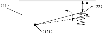
- WO
- WIPO (PCT)
- Prior art keywords
- sheet
- flow
- elastic structure
- fluid
- cold plate
- Prior art date
- Legal status (The legal status is an assumption and is not a legal conclusion. Google has not performed a legal analysis and makes no representation as to the accuracy of the status listed.)
- Ceased
Links
Images




Classifications
-
- H—ELECTRICITY
- H05—ELECTRIC TECHNIQUES NOT OTHERWISE PROVIDED FOR
- H05K—PRINTED CIRCUITS; CASINGS OR CONSTRUCTIONAL DETAILS OF ELECTRIC APPARATUS; MANUFACTURE OF ASSEMBLAGES OF ELECTRICAL COMPONENTS
- H05K7/00—Constructional details common to different types of electric apparatus
- H05K7/20—Modifications to facilitate cooling, ventilating, or heating
-
- H—ELECTRICITY
- H05—ELECTRIC TECHNIQUES NOT OTHERWISE PROVIDED FOR
- H05K—PRINTED CIRCUITS; CASINGS OR CONSTRUCTIONAL DETAILS OF ELECTRIC APPARATUS; MANUFACTURE OF ASSEMBLAGES OF ELECTRICAL COMPONENTS
- H05K7/00—Constructional details common to different types of electric apparatus
- H05K7/20—Modifications to facilitate cooling, ventilating, or heating
- H05K7/2029—Modifications to facilitate cooling, ventilating, or heating using a liquid coolant with phase change in electronic enclosures
Definitions
- Embodiments of the present invention relate to the field of phase change heat dissipation technologies, and in particular, to a cold plate and a method of manufacturing and using the same.
- Liquid cooling technology generally refers to the dissipation of heat from a communication device by inserting a plurality of cold plates into the communication device and through the flow of liquid inside the cold plate.
- the two-phase heat exchange technology refers to the principle of using a working medium to change a large amount of latent heat of vaporization from a liquid to a gas, and takes away a large amount of heat.
- the two-phase heat transfer technology is applied to the cold plate, so that the fluid flowing into the cold plate is a liquid, and the fluid flowing in the cold plate is usually a gas or liquid mixture.
- the fluid flowing out of the cold plate is a gas, a liquid mixture or a gas, so that a large amount of heat is taken away by the two-phase heat exchange, and the temperature of the communication device is lowered.
- the fluid flowing inside the cold plate is usually a gas-liquid mixture
- the fluid inside the cold plate is The flow direction is also different.
- the fluid inside the cold plate flows from top to bottom, it is affected by gravity, and the buoyancy force of the bubble is large. The bubble moves upward under the action of the floating force, and the gas in the fluid is prone to air blockage. As a result, heat dissipation is deteriorated.
- the existing part of the communication device is a cabinet with two frames, the upper and lower frames are mirrored, and the inserted cold plates in the upper and lower frames are also mirrored.
- a cold plate is inserted into the upper frame and the fluid flow direction inside the cold plate is as shown in Fig. 1a
- the flow direction of the fluid inside the cold plate can be as shown in Fig. 1b.
- the gas in the upper cold plate of the outlet shown in Fig. 1a will be easily discharged; and in the case shown in Fig. 1b, the bubble moves upward under the action of the lifting force, so the outlet A gas blockage will appear below, which will cause heat dissipation to deteriorate.
- the embodiment of the invention provides a cold plate and a manufacturing and using method thereof, which can at least solve the problem that at least when the fluid inside the cold plate adopting the two-phase heat exchange technology flows from the top to the bottom, the gas in the fluid is prone to air blockage. Phenomenon, which causes problems in heat dissipation.
- a cold plate (1) comprising a cold plate body (10) and n flow channels (11) inside the cold plate body (10), n being a positive integer, n flow channels (11) Within each of the m flow channels (11), at least one sheet-like elastic structure (12) is provided, m being a positive integer less than or equal to n.
- the sheet-like elastic structure (12) may include a fixed end (121) and a movable end (122).
- the sheet-like elastic structure (12) is fixed on the inner wall of the flow path (11) through the fixed end (121), and the fixed end ( 121) approaching the first port (13) of the flow path (11) along the flow path (11), live
- the movable end (122) is adjacent to the second port (14) of the flow path (11) in the direction of the flow path (11).
- the sheet-like elastic structure when the fluid flows from the first port to the second port, if the fluid flow rate is small and the excitation of the sheet-like elastic structure is less than or equal to a predetermined threshold, the sheet-like elastic structure is not deformed, and the fluid is in the flow path.
- the flow cross section at the elastic structure becomes smaller, the surface force of the bubble in the fluid is equal to the floating force, and the bubble is discharged under the inertial force; if the fluid flow is large, the excitation increases and is greater than the preset threshold, then the sheet elastic
- the deformation of the structure causes the flow cross section of the fluid in the flow passage to increase at the sheet-like elastic structure.
- the inertial force of the fluid predominates, and the bubble is discharged under the action of the inertial force.
- the fluid flowing in from the first port (13) is a liquid
- the fluid flowing out of the second port (14) is a gas, a liquid mixture or a gas.
- the m flow channels (11) have a large width value among the n flow channels (11) The flow path.
- the narrower flow channel has a larger surface force on the bubble, the counteracting effect on the floating force is larger, and the wider flow channel has a smaller surface force on the bubble, and the counteracting effect on the floating force is smaller, and the bubble is subjected to the lifting force.
- the influence is large, and thus a sheet-like elastic structure should be provided in a wider flow passage.
- the sheet-like elastic structure (12) is active when no deformation occurs.
- the distance between the end (122) and the target inner wall (15) is less than 0.5 mm, and the target inner wall (15) is the opposite inner wall of the inner wall where the fixed end (121) is located.
- the surface force of the bubble is sufficient to overcome the floating force, so that when the fluid flow is small and the sheet-like elastic structure is not deformed, the gas in the fluid can be caused by the inertial force. Smoothly discharged.
- the liquid flowing from the second port (14) flows back to the first The port (13), the gas flowing out of the second port (14) flows to the heat radiating unit.
- phase change easily occurs to become a gas, thereby taking away a large amount of heat of the communication device.
- a communication device comprising the cold plate in any of the above possible implementations of the first aspect or the first aspect.
- a third aspect provides a method for manufacturing a cold plate, comprising: manufacturing a cold plate body; and providing n flow channels inside the cold plate body, n being a positive integer; each of the m flow channels of the n flow channels In the track, at least one sheet-like elastic structure is provided, m is a positive integer less than or equal to n, and the sheet-like elastic structure
- the fixed end and the movable end comprise a sheet-like elastic structure fixed on the inner wall of the flow channel through the fixed end, the fixed end is adjacent to the first port of the flow channel in the flow channel direction, and the movable end is adjacent to the second port of the flow channel in the flow channel direction;
- a method of using a cold plate which is the cold plate (1) in any one of the first aspect or the first aspect of the first aspect, the method of using the method comprises: using a cold plate Flowing from the first port of the inner flow passage of the cold plate; flowing fluid from the second port of the inner flow passage of the cold plate.
- Cold plate Located inside the communication device, the communication device is cooled by the fluid flowing in the cold plate.
- Air blockage The gas in the fluid collects together and cannot be discharged, and it also hinders the flow of liquid in the fluid.
- Inertia force When the object has acceleration, the inertia of the object will make the object have the tendency to maintain the original motion state. At this time, if the object is used as the reference system and the coordinate system is established on the reference frame, it looks like it seems to be There is a force in the opposite direction acting on the object to cause the object to move within the coordinate system, hence the inertial force.
- Floating force The fluid forms a density difference due to the uneven temperature of each part, thereby generating a force for moving the fluid in a gravity field or other force field, and the force is a floating force.
- Surface force A force acting on the outer surface of a fluid that is proportional to the surface area.
- Flow resistance The force acting on the flowing fluid by the object at the flow boundary is opposite to the flow direction of the fluid and is generated by the transfer of momentum.
- 1a is a schematic view showing the structure of a cold plate of a fluid outlet upward provided in the prior art
- Figure 1b is a schematic view showing the structure of a cold plate of a fluid outlet downward provided in the prior art
- FIG. 2 is a schematic structural diagram of a communication device provided with a cold plate according to an embodiment of the present invention
- FIG. 3 is a schematic structural diagram of a cold plate according to an embodiment of the present invention.
- FIG. 4a is a schematic structural view of a sheet-like elastic structure according to an embodiment of the present invention.
- FIG. 4b is a schematic structural view of another sheet-like elastic structure according to an embodiment of the present invention.
- FIG. 5 is a schematic structural diagram of another sheet-like elastic structure according to an embodiment of the present invention.
- FIG. 6 is a schematic structural diagram of another sheet-like elastic structure according to an embodiment of the present invention.
- FIG. 7 is a schematic structural diagram of another sheet-like elastic structure according to an embodiment of the present invention.
- FIG. 8 is a schematic structural diagram of another sheet-like elastic structure according to an embodiment of the present invention.
- FIG. 9 is a schematic structural diagram of another sheet-like elastic structure according to an embodiment of the present invention.
- FIG. 10 is a schematic structural diagram of another sheet-like elastic structure according to an embodiment of the present invention.
- FIG. 11 is a schematic structural diagram of another sheet-like elastic structure according to an embodiment of the present invention.
- FIG. 12 is a flowchart of a method for manufacturing a cold plate according to an embodiment of the present invention.
- FIG. 13 is a flowchart of a method for using a cold plate according to an embodiment of the present invention.
- the cold plate When using liquid cooling technology for heat dissipation, the cold plate is usually placed on the circuit board of the communication device.
- the cold plate of the communication device usually consists of multiple blocks, and each cold plate may include multiple flow channels and multiple flows inside.
- the channels are usually arranged in parallel, and the communication device is dissipated through fluid flowing inside each channel.
- the specific shape of each cold plate in different communication devices can be set as needed, for example, it can be an L shape or a straight bar shape.
- an embodiment of the present invention provides a cold plate, wherein a sheet-like elastic structure is disposed inside the cold plate flow passage, and whether the fluid in the flow passage is at the sheet elastic structure is controlled by whether the sheet elastic structure is deformed.
- the size of the flow cross section allows the gas to escape smoothly.
- the cold plate (1) may include a cold plate body (10) and n flow channels (11) inside the cold plate body (10), where n is A positive integer, in each of the m flow channels (11) of the n flow channels (11), at least one sheet-like elastic structure (12) is provided, and m is a positive integer smaller than or equal to n .
- the sheet-like elastic structure (12) may include a fixed end (121) and a movable end (122).
- the sheet-like elastic structure (12) is fixed on the inner wall of the flow path (11) through the fixed end (121), and the fixed end ( 121) A first port (13) adjacent to the flow channel (11) in the direction of the flow channel (11), the movable end (122) being adjacent to the second port (14) of the flow channel (11) in the direction of the flow channel (11).
- the sheet-like elastic structure (12) deforms when excited by a predetermined threshold, so that the fluid in the flow channel (11) is
- the flow cross section at the sheet-like elastic structure (12) is increased, and the magnitude of the excitation is positively correlated with the flow rate of the fluid inside the flow passage (11).
- the flow channel (11) provided with the sheet-like elastic structure (12) may be all the flow channels (11), or may be only part of the flow channels (11).
- a sheet-like elastic structure (12) may be disposed in each of the flow channels (11), or a plurality of sheet-like elastic structures (12) may be disposed, which are not specifically limited herein.
- the first port (13) of the fixed end (121) adjacent to the flow channel (11) in the direction of the flow channel (11) means that the fixed end (121) reaches the first port along the direction in which the flow channel (11) is disposed ( The path of 13) is short, and the path to the second port (14) along the direction in which the flow path (11) is disposed is long.
- the second port (14) of the movable end (122) adjacent to the flow path (11) along the flow path (11) means that the movable end (122) reaches the second port along the direction in which the flow path (11) is disposed ( The path of 14) is short, and the path to the first port (13) along the direction in which the flow path (11) is arranged is long.
- a flow path (11) includes a plurality of sheet-like elastic structures (12), the fixed ends (121) and the movable ends (122) of all the sheet-like elastic structures (12) in the flow path (11)
- the setting direction in the flow path (11) can be kept consistent, and the flow path (11)
- the fixed ends (121) of the inner sheet-like elastic structure (12) are all close to the first port (13), and the movable end (122) of the sheet-like elastic structure (12) in the flow path (11) is close to the second port (14).
- the sheet-like elastic structure (12) refers to a structure having a certain area and elastic deformation, and the specific shape of the embodiment of the present invention is not limited.
- “having a certain area” indicates that the sheet-like elastic structure (12) has a certain width and occupies a part of the flow passage (11).
- the positive correlation between the magnitude of the excitation and the flow rate of the fluid inside the flow channel (11) means that the larger the flow rate of the fluid inside the flow channel (11), the greater the excitation; the smaller the flow rate of the fluid inside the flow channel (11), The smaller the incentive.
- the preset threshold here may be a critical value of the excitation that causes the sheet-like elastic structure (12) to deform.
- the cold plate (1) adopts a two-phase heat exchange technology
- the fluid flowing into the cold plate (1) is a liquid
- the fluid flowing out of the cold plate (1) is a gas and liquid mixture.
- the fluid flowing from the first port (13) may be a liquid
- the fluid flowing from the second port (14) may be a gas or liquid mixture or Gas
- the sheet-like elastic structure (12) is deformed when excited by a predetermined threshold, so that the flow cross section of the fluid in the flow passage (11) at the sheet-like elastic structure (12) is increased, and the excitation
- the size is positively related to the flow rate of the fluid inside the runner (11).
- the air bubbles are easily removed from the second port (14) discharge.
- the fluid flows from the first port (13) to the second port (14), if the first port (13) is above, the second port (14) is below, and the flow of fluid inside the flow channel (11) is small.
- the sheet-like elastic structure (12) is subjected to an excitation less than or equal to a preset threshold value so that deformation does not occur, and since the sheet-like elastic structure (12) has a certain area, it occupies a part of the cross-sectional area inside the flow passage (11).
- the flow cross section of the fluid at the sheet-like elastic structure (12) in the flow passage (11) becomes small, so that the surface force of the bubble at the sheet-like elastic structure (12) becomes large, and is equal to the buoyancy force received by the bubble, thereby To counteract the effect of the lifting force, at which time the bubble is discharged under the action of the inertial force; when the flow of the fluid inside the flow channel (11) is increased, so that the excitation of the sheet-like elastic structure (12) is greater than a preset threshold, the sheet-like elastic structure (12) Deformation occurs such that the flow cross section of the fluid in the flow passage (11) at the sheet-like elastic structure (12) is increased, at which time the inertial force of the fluid predominates, and the inertial force is greater than the lift force regardless of the surface force How much counteracting effect on the lift force can make the bubble Exhausted under the influence of sexual force.
- the first port (13) is above or below, that is, whether the fluid in the inner flow channel (11) of the cold plate (1) is from top to bottom.
- the flow also flows from bottom to top, as long as the fluid flows from the first port (13) of the flow channel (11) to the second port (14), the gas in the fluid can be easily discharged from the second port (14) without A gas blockage will occur, resulting in deterioration of heat dissipation.
- the specific form of the excitation of the sheet-like elastic structure (12) can be set according to actual needs.
- the excitation of the sheet-like elastic structure (12) may be the impact of the fluid inside the flow passage (11) on the sheet-like elastic structure (12).
- the greater the fluid flow the greater the impact of the fluid on the sheet-like elastic structure (12) and the greater the excitation of the sheet-like elastic structure (12).
- the fluid flow rate is increased to a certain extent, the impact force of the fluid on the sheet-like elastic structure (12) reaches a preset threshold, and the sheet-like elastic structure (12) is deformed, so that the fluid in the flow channel (11) is in the sheet-like elasticity.
- the flow cross section at the structure (12) is increased.
- the excitation of the sheet-like elastic structure (12) may also be the force of at least one of the applied electric or magnetic fields on the sheet-like elastic structure (12).
- the sheet-like elastic structure (12) is located in an electric field when flowing When the flow rate of the fluid in the channel (11) is increased, the force of the electric field on the sheet-like elastic structure (12) is enhanced, and the excitation of the sheet-like elastic structure (12) is increased.
- the force of the electric field on the sheet-like elastic structure (12) reaches a predetermined threshold, and the sheet-like elastic structure (12) is deformed, so that the flow passage (11) The flow cross section of the fluid at the sheet-like elastic structure (12) is increased.
- the sheet-like elastic structure (12) may be an elastic sheet, and the elastic sheet is bent toward the inner wall of the fixed end (121) when excited by a predetermined threshold.
- the flow cross section of the fluid in the flow passage (11) at the elastic sheet is increased.
- the elastic sheet may specifically be in the shape of a leaf, see FIG. 4b, or other shapes, which are not specifically limited herein.
- the sheet-like elastic structure (12) may be a spring-shaped sheet-like baffle supported by the inner wall of the fixed end (121) and the sheet-like baffle.
- the sheet-like baffle deforms when the excitation is greater than a predetermined threshold, such that the flow cross-section of the fluid in the flow passage (11) at the sheet-like baffle increases.
- the sheet-like elastic structure (12) is mainly deformed by the sheet-shaped baffle compression spring, so that the flow cross section of the fluid in the flow passage (11) at the sheet-shaped baffle is increased, and the sheet-shaped baffle itself It may or may not be an elastic structure.
- the spring herein may be replaced with other elastic structures, for example, a torsion bar as shown in FIG.
- the fixed end (121) and the movable end (122) of all the sheet-like elastic structures (12) in the flow channel (11) need to be arranged in the same direction, that is, the fixed end (121) needs to be along the flow path (11).
- the direction is close to the first port (13), and the movable end (122) needs to be close to the second port (14) in the direction of the flow channel (11), otherwise the heat dissipation effect of the cold plate (1) will be affected, resulting in deterioration of heat dissipation.
- the flow path (11) includes a first sheet-like elastic structure and a second sheet-like elastic structure
- the fixed end (121) of the first sheet-like elastic structure is close to the first port ( 13)
- the movable end (122) of the first sheet-like elastic structure is adjacent to the second port (14), and the fixed end (121) of the second sheet-like elastic structure is adjacent to the second port (14), and the second sheet-like elastic structure is
- the movable end (122) is close to the first port (13), when the fluid flows from the first port (13) to the second port (14), and the first port (13) is above and the second port (14) is below If the fluid flow rate is large, the first sheet-like elastic structure is deformed as indicated by a broken line in FIG.
- the fixed end (121) of the sheet-like elastic structure (12) is close to the first port (13) in the direction of the flow channel (11)
- the movable end (122) is adjacent to the second port (14) in the direction of the flow passage (11), and when the fluid flows from the second port (14) to the first port (13), the fluid is moved by the movable end of the sheet-like elastic structure (12). (122) Flows to the fixed end (121). If the fluid flow rate is large, the sheet-like elastic structure (12) may be deformed as indicated by a broken line in Fig. 9, so that the flow cross section of the fluid in the flow path (11) at the sheet-like elastic structure (12) is reduced.
- the air bubbles move upward under the action of the floating force, thereby causing a gas blockage phenomenon, which causes a problem of heat dissipation deterioration, and can also pass the width of the flow channel.
- a gas blockage phenomenon which causes a problem of heat dissipation deterioration
- the width of the flow channel Assume It is narrowed to increase the surface force of the inner wall of the flow passage against the bubble so that the surface force is sufficient to overcome the floating force, so that the gas can be smoothly discharged.
- reducing the width of the entire flow path greatly increases the flow resistance of the fluid, thereby impeding the flow of the fluid, resulting in deterioration of the heat dissipation of the cold plate.
- the flow path (11) is reduced.
- the partial flow cross section but does not increase the flow resistance of the fluid excessively compared to the width of the entire flow passage (11), and does not affect the discharge of the fluid due to the small fluid flow rate, and does not cause cold
- the heat dissipation of the plate (1) is deteriorated; when the fluid flow rate is large and the sheet-like elastic structure (12) in the flow path (11) is deformed, the flow cross section at the sheet-like elastic structure (12) in the flow path (11) can be made.
- the fluid is discharged by the inertial force, and thus does not cause the heat dissipation of the cold plate (1) to deteriorate.
- the m flow channels (11) may be flow channels (11) having a large width value among the n flow channels (11).
- the width values of the different flow channels (11) in the cold plate body (10) may be the same or different, for example, the width value may be 3 mm, 2 mm, 1 mm, or the like.
- the narrower flow channel (11) has a larger surface force on the bubble, the counteracting effect on the floating force is greater, while the wider flow channel (11) has a smaller surface force on the bubble, offsetting the floating force. The effect is small, and the bubble is greatly affected by the lifting force, so that the sheet-like elastic structure (12) should be disposed in the wider flow channel (11).
- the distance between the movable end (122) and the target inner wall (15) is less than 0.5 mm, and the target inner wall (15) It is the opposite inner wall of the inner wall where the fixed end (121) is located.
- the distance between the movable end (122) and the target inner wall (15) is less than 0.5 mm, the surface force of the bubble is sufficient to overcome the floating force, so that when the fluid flow rate is small and the sheet-like elastic structure (12) is not deformed, it can be made The gas in the fluid is smoothly discharged by the inertial force.
- the liquid flowing out from the second port (14) can be returned to the first port (13), and the gas flowing out from the second port (14) can flow to the heat dissipation.
- the unit, the heat dissipating unit is a unit for dissipating heat from the inside to the outside of the communication device.
- a cold plate (1) provided by an embodiment of the present invention has a sheet-like elastic structure (12) disposed in a flow passage (11) therein, and the sheet-like elastic structure (12) includes a fixed end (121) and a movable end ( 122), the fixed end (121) is close to the first port (13) of the flow channel (11), the movable end (122) is close to the second port (14) of the flow channel (11), and the fluid is from the first port (13)
- the second port (14) if the fluid flow rate is small and the excitation of the sheet-like elastic structure (12) is less than or equal to a predetermined threshold, the sheet-like elastic structure (12) will not be deformed, and the fluid is in the flow path ( 11)
- the flow cross section at the inner sheet-like elastic structure (12) becomes smaller, the surface force of the bubble in the fluid is equal to the floating force, and the bubble is discharged under the action of the inertial force; if the fluid flow rate is large, the excitation is increased and larger than By preset threshold, the sheet
- the cold plate (1) provided by the embodiment of the present invention can smoothly discharge the gas in the fluid, thereby being able to solve the prior art.
- the gas in the fluid is liable to cause a gas blockage phenomenon, thereby causing a problem of heat dissipation deterioration.
- Another embodiment of the present invention provides a communication device, which may include the foregoing apparatus embodiment.
- Cold plate (1) When the communication device is dissipated using the above-described cold plate (1), the fluid in the cold plate (1) flows from the first port (13) of the flow path (11) to the second port (14).
- Another embodiment of the present invention provides a method for manufacturing a cold plate.
- the cold plate adopts a two-phase heat exchange technology, and the fluid flowing from the first port may be a liquid, and the fluid flowing out from the second port may be a gas or liquid mixture.
- gas see Figure 12, the method can include:
- each of the m flow channels of the n flow channels at least one sheet-like elastic structure is disposed, where m is a positive integer less than or equal to n, and the sheet-like elastic structure includes a fixed end and a movable end, and the sheet elastic The structure is fixed on the inner wall of the flow channel through the fixed end, the fixed end is adjacent to the first port of the flow channel in the flow channel direction, and the movable end is adjacent to the second port of the flow channel in the flow channel direction.
- the sheet-like elastic structure deforms when excited by a predetermined threshold, such that a flow cross section of the fluid in the flow path at the sheet-like elastic structure increases.
- the excitation of the sheet-like elastic structure is less than or equal to a preset threshold, deformation does not occur, and the fluid flows in the sheet-like elastic structure in the flow channel.
- the cross-section becomes smaller, the surface force of the bubble in the fluid is equal to the floating force, and the bubble is discharged under the action of the inertial force;
- the fluid flow is large, the excitation increases and is greater than the preset threshold, the sheet-like elastic structure is deformed, so that The flow cross section of the fluid in the flow channel increases at the sheet-like elastic structure, at which time the inertial force of the fluid predominates, and the bubble is discharged under the action of the inertial force.
- the cold plate manufactured in the embodiment of the present invention can smoothly discharge the gas in the fluid regardless of whether the first port is above or the second port is above.
- the excitation of the sheet-like elastic structure may include an impact force of the fluid inside the flow channel on the sheet-like elastic structure, or an action of at least one of the applied electric field or the magnetic field on the sheet-like elastic structure.
- the providing at least one sheet-like elastic structure in each of the m flow channels of the n flow channels may include:
- At least one sheet-like elastic structure is provided in each of the m flow paths having a large width value of the n flow paths. Since the narrower flow channel has a larger surface force on the bubble, the counteracting effect on the floating force is larger, and the wider flow channel has a smaller surface force on the bubble, and the counteracting effect on the floating force is smaller, and the bubble is subjected to the lifting force. The influence is large, so it should be preferred to provide a sheet-like elastic structure in a wider flow path.
- a method for manufacturing a cold plate according to an embodiment of the present invention wherein a flow path is disposed inside the cold plate body, and a sheet-like elastic structure is disposed in the flow path, the sheet-like elastic structure includes a fixed end and a movable end, and the fixed end is adjacent to the flow path.
- the first port, the movable end is close to the second port of the flow channel, so that when the fluid flows from the first port to the second port, if the fluid flow is small, the excitation of the sheet-like elastic structure is less than or equal to a preset threshold, then the sheet is The elastic structure does not deform, the flow cross section of the fluid in the sheet-like elastic structure in the flow channel becomes smaller, the surface force of the bubble in the fluid is equal to the floating force, and the bubble is discharged under the inertial force; if the fluid flow rate is large, When the excitation is increased to be greater than the preset threshold, the sheet-like elastic structure is deformed, so that the flow cross section of the fluid in the flow passage increases at the sheet-like elastic structure, and the inertial force of the fluid predominates, and the bubble is in the inertial force.
- the gas in the cold plate fluid can be smoothly discharged, so that the fluid in the cold plate inside the cold plate adopting the two-phase heat exchange technology can be solved from the upward direction in the prior art.
- the gas in the fluid is prone to air blockage, which causes a problem of heat dissipation deterioration.
- Another embodiment of the present invention provides a method of using a cold plate which is the cold plate (1) provided in the above embodiment of the apparatus.
- the cold plate adopts a two-phase heat exchange technique, and the fluid flowing in from the first port may be a liquid, and the fluid flowing out from the second port may be a gas, a liquid mixture or a gas.
- the cold plate may include n cold runner bodies and n flow channels inside the cold plate body, n is a positive integer, and each of the m flow channels of the n flow channels is provided with at least one sheet-like elastic structure, where m is a positive integer less than or equal to n, the sheet-like elastic structure includes a fixed end and a movable end, and the sheet-like elastic structure is fixed on the inner wall of the flow channel through the fixed end, and the fixed end is adjacent to the first port of the flow channel in the flow channel direction, and the movable end a second port along the flow path adjacent to the flow channel, when the fluid flows from the first port to the second port, the sheet-like elastic structure is deformed when excited by a predetermined threshold, so that the fluid in the flow channel is in the sheet-like elastic structure.
- the flow cross section at the point is increased, and the magnitude of the excitation is positively correlated with the flow rate of the fluid inside the flow passage.
- the usage method may include:
- the fluid flows from the first port of the inner flow passage of the cold plate.
- the flow path of the cold plate is provided with a sheet-like elastic structure
- the sheet-like elastic structure includes a fixed end and a movable end, and the fixed end is adjacent to the first port of the flow channel, and the movable
- the second port of the end adjacent to the flow passage is configured to flow fluid from the first port of the inner flow passage of the cold plate to flow the fluid from the second port of the inner flow passage of the cold plate, so that when the fluid flow rate is small, the sheet-like elastic structure is subjected to The excitation is less than or equal to the preset threshold, the sheet-like elastic structure is not deformed, the flow cross section of the fluid in the sheet-like elastic structure in the flow channel becomes small, and the surface force of the bubble in the fluid is equal to the floating force, and the bubble is in the inertial force.
- the fluid flow is made larger, so that when the excitation is increased and is greater than the preset threshold, the sheet-like elastic structure is deformed, so that the flow cross section of the fluid in the flow passage increases at the sheet-like elastic structure, and the inertia of the fluid at this time
- the force dominates and the bubbles are expelled by the inertial force. Therefore, whether the first port is above or the second port is above, the gas in the cold plate fluid can be smoothly discharged, so that the fluid in the cold plate inside the cold plate adopting the two-phase heat exchange technology can be solved from the upward direction in the prior art.
- the gas in the fluid When flowing downward, the gas in the fluid is prone to air blockage, which causes a problem of heat dissipation deterioration.
Landscapes
- Engineering & Computer Science (AREA)
- Microelectronics & Electronic Packaging (AREA)
- Physics & Mathematics (AREA)
- Thermal Sciences (AREA)
- Cooling Or The Like Of Electrical Apparatus (AREA)
- Cooling Or The Like Of Semiconductors Or Solid State Devices (AREA)
Abstract
本发明实施例提供一种冷板及制造和使用方法,涉及相变散热技术领域,至少能够解决现有技术中,采用两相换热技术的冷板内部的流体由上向下流动时,流体中的气体容易出现气堵现象,从而导致散热恶化的问题。该冷板包括冷板本体和冷板本体内部的n个流道,其中的m个流道中的每个流道内设置有至少一个片状弹性结构,片状弹性结构包括固定端和活动端,固定端沿流道方向靠近流道的第一端口,活动端沿流道方向靠近流道的第二端口,当流体由第一端口流向第二端口时,片状弹性结构在受到大于预设阈值的激励时发生形变,使得流道内的流体在片状弹性结构处的流通截面增大,激励的大小与流道内部流体的流量大小正相关。本发明实施例用于散热。
Description
本申请要求于2016年6月16日提交中国专利局、申请号为201610430542.1、发明名称为“一种冷板及制造和使用方法”的中国专利申请的优先权,其全部内容通过引用结合在本申请中。
本发明实施例涉及相变散热技术领域,尤其涉及一种冷板及制造和使用方法。
液冷技术通常是指,通过在通信设备中插入多块冷板,并通过冷板内部液体的流动对通信设备进行散热。两相换热技术是指,利用工质从液体变为气体吸收大量汽化潜热的原理,带走大量的热量。与传统冷板流入、流出的流体都是液体相比,将两相换热技术应用到冷板中,可以使得流入冷板的流体为液体,在冷板内流动的流体通常为气、液混合体,流出冷板的流体为气、液混合体或气体,从而通过两相换热带走大量的热量,降低通信设备的温度。
对于采用两相换热技术的同一块冷板来说,由于冷板内部流动的流体通常为气、液混合体,冷板插入通信设备的位置不同或插入的方向不同时,冷板内部流体的流动方向也不同,当冷板内部的流体由上向下流动时,受到重力影响,气泡受到的浮升力较大,气泡在浮升力作用下朝上运动,流体中的气体容易出现气堵现象,从而导致散热恶化。
例如,现有部分通信设备为一柜两框式,上、下两框镜像,上、下两框中的插入的冷板也镜像放置。当上框中插入一块冷板且该冷板内部流体流动方向如图1a所示时,若将该冷板插入下框中,则冷板内部流体的流动方向可以如图1b所示。采用两相换热技术后,如图1a所示的出口在上方的冷板中的气体将很容易排出;而对于如图1b所示的情况,气泡在浮升力作用下朝上运动,因此出口在下方将会出现气堵现象,从而导致散热恶化。
发明内容
本发明实施例提供一种冷板及制造和使用方法,至少能够解决现有技术中,采用两相换热技术的冷板内部的流体由上向下流动时,流体中的气体容易出现气堵现象,从而导致散热恶化的问题。
第一方面,提供一种冷板(1),包括冷板本体(10)和冷板本体(10)内部的n个流道(11),n为正整数,n个流道(11)的m个流道(11)中的每个流道(11)内,设置有至少一个片状弹性结构(12),m为小于或者等于n的正整数。其中,片状弹性结构(12)可以包括固定端(121)和活动端(122),片状弹性结构(12)通过固定端(121)固定在流道(11)的内壁上,固定端(121)沿流道(11)方向靠近流道(11)的第一端口(13),活
动端(122)沿流道(11)方向靠近流道(11)的第二端口(14)。当流体由第一端口(13)流入且由第二端口(14)流出时,片状弹性结构(12)在受到大于预设阈值的激励时发生形变,使得流道(11)内的流体在片状弹性结构(12)处的流通截面增大,激励的大小与流道(11)内部流体的流量大小正相关。
这样,在流体由第一端口流向第二端口时,若流体流量较小,片状弹性结构受到的激励小于或者等于预设阈值,则片状弹性结构不会发生形变,流体在流道内片状弹性结构处的流通截面变小,流体中的气泡受到的表面力与浮升力持平,气泡在惯性力作用下排出;若流体流量较大,使得激励增大从而大于预设阈值,则片状弹性结构发生形变,使得流道内的流体在片状弹性结构处的流通截面增大,此时流体的惯性力占主导作用,气泡在惯性力的作用下排出。因而,无论第一端口在上方还是第二端口在上方,冷板中的气体均能够顺利排出。
结合第一方面,在第一方面的第一种可能的实现方式中,从第一端口(13)流入的流体为液体,从第二端口(14)流出的流体为气、液混合体或气体。
结合第一方面或第一方面的第一种可能的实现方式,在第一方面的第二种可能的实现方式中,m个流道(11)为n个流道(11)中宽度值大的流道。
由于较窄的流道对气泡的表面力较大,对浮升力的抵消作用较大,而较宽的流道对气泡的表面力较小,对浮升力的抵消作用较小,气泡受浮升力的影响较大,因而较宽的流道内更应设置片状弹性结构。
结合第一方面至第一方面的第二种可能的实现方式中的任意一种,在第一方面的第三种可能的实现方式中,片状弹性结构(12)在未发生形变时,活动端(122)与目标内壁(15)的距离小于0.5mm,目标内壁(15)为固定端(121)所在内壁的对向内壁。
当活动端与目标内壁的距离小于0.5mm时,气泡受到的表面力足以克服浮升力,从而在流体流量较小,片状弹性结构未发生形变时,能够使得流体中的气体在惯性力的作用下顺利排出。
结合第一方面至第一方面的第三种可能的实现方式中的任意一种,在第一方面的第四种可能的实现方式中,从第二端口(14)流出的液体回流至第一端口(13),从第二端口(14)流出的气体流向散热单元。
这样,由于从第二端口流出的液体的温度本来就较高,不经冷却而直接回流至第一端口时,很容易发生相变而变成气体,从而带走通信设备大量的热量。
第二方面,提供一种通信设备,包括上述第一方面或第一方面的任意一种可能的实现方式中的冷板。
第三方面,提供一种冷板的制造方法,包括:制造冷板本体;在冷板本体内部设置n个流道,n为正整数;在n个流道的m个流道中的每个流道内,设置至少一个片状弹性结构,m为小于或者等于n的正整数,片状弹性结构
包括固定端和活动端,片状弹性结构通过固定端固定在流道的内壁上,固定端沿流道方向靠近流道的第一端口,活动端沿流道方向靠近流道的第二端口;当流体由第一端口流向第二端口时,片状弹性结构在受到大于预设阈值的激励时发生形变,使得流道内的流体在片状弹性结构处的流通截面增大,激励的大小与流道内部流体的流量大小正相关。
第四方面,提供一种冷板的使用方法,该冷板为上述第一方面或第一方面的任意一种可能的实现方式中的冷板(1),该使用方法包括:使用冷板时,将流体从冷板内部流道的第一端口流入;将流体从冷板内部流道的第二端口流出。
为达到上述目的,本发明的实施例采用如下技术方案:
为了便于理解,示例的给出了部分与本发明相关概念的说明以供参考。如下所示:
冷板:位于通信设备内部,通过冷板中流动的流体对通信设备进行散热。
气堵:流体中的气体聚集在一起无法排出,同时还会阻碍流体中液体的流动。
惯性力:当物体有加速度时,物体具有的惯性会使物体有保持原有运动状态的倾向,而此时若以该物体为参考系,并在该参考系上建立坐标系,看起来就仿佛有一股方向相反的力作用在该物体上令该物体在坐标系内发生位移,因此称之为惯性力。
浮升力:流体由于各部分温度不均匀形成密度差,从而在重力场或其它力场中产生使流体运动的力,该力即为浮升力。
表面力:作用在流体外表面上与表面积成正比的力。
流动阻力:流动边界的物体对流动流体的作用力,与流体的流动方向相反,由动量传递而产生。
图1a为现有技术中提供的一种流体出口向上的冷板结构示意图;
图1b为现有技术中提供的一种流体出口向下的冷板结构示意图;
图2为本发明实施例提供的一种设置有冷板的通信设备的结构示意图;
图3为本发明实施例提供的一种冷板的结构示意图;
图4a为本发明实施例提供的一种片状弹性结构的结构示意图;
图4b为本发明实施例提供的另一种片状弹性结构的结构示意图;
图5为本发明实施例提供的另一种片状弹性结构的结构示意图;
图6为本发明实施例提供的另一种片状弹性结构的结构示意图;
图7为本发明实施例提供的另一种片状弹性结构的结构示意图;
图8为本发明实施例提供的另一种片状弹性结构的结构示意图;
图9为本发明实施例提供的另一种片状弹性结构的结构示意图;
图10为本发明实施例提供的另一种片状弹性结构的结构示意图;
图11为本发明实施例提供的另一种片状弹性结构的结构示意图;
图12为本发明实施例提供的一种冷板的制造方法流程图;
图13为本发明实施例提供的一种冷板的使用方法流程图。
附图标记:
(1)-冷板;(10)-冷板本体;(11)-流道;(12)-片状弹性结构;(121)-固定端;(122)-活动端;(13)-第一端口;(14)-第二端口;(15)-目标内壁。
采用液冷技术进行散热时,冷板通常贴着通信设备的电路板设置,参见图2,通信设备的冷板通常由多块组成,每块冷板内部可以包括多个流道,多个流道通常是平行设置的,通过各流道内部流动的流体对通信设备进行散热。其中,不同通信设备中每块冷板的具体形状可以根据需要进行设定,例如可以是L形,也可以是直条形等。当冷板采用两相换热技术时,若冷板内部的流体由上向下流动,则流体中的气体容易出现气堵现象,从而导致散热恶化。
为了解决上述问题,本发明实施例提供一种冷板,冷板流道内部设置有片状弹性结构,并通过片状弹性结构是否发生形变,来控制流道内的流体在片状弹性结构处的流通截面的大小,从而使得气体顺利排出。以下将通过具体实施例进行详细描述。
本发明实施例提供一种冷板(1),参见图3,该冷板(1)可以包括冷板本体(10)和冷板本体(10)内部的n个流道(11),n为正整数,n个流道(11)的m个流道(11)中的每个流道(11)内,设置有至少一个片状弹性结构(12),m为小于或者等于n的正整数。其中,片状弹性结构(12)可以包括固定端(121)和活动端(122),片状弹性结构(12)通过固定端(121)固定在流道(11)的内壁上,固定端(121)沿流道(11)方向靠近流道(11)的第一端口(13),活动端(122)沿流道(11)方向靠近流道(11)的第二端口(14)。当流体由第一端口(13)流入且由第二端口(14)流出时,片状弹性结构(12)在受到大于预设阈值的激励时发生形变,使得流道(11)内的流体在片状弹性结构(12)处的流通截面增大,激励的大小与流道(11)内部流体的流量大小正相关。
其中,m小于或者等于n,即设置有片状弹性结构(12)的流道(11)可以是全部流道(11),也可以仅是其中的部分流道(11)。并且,每个流道(11)中可以设置一个片状弹性结构(12),也可以设置多个片状弹性结构(12),这里不做具体限定。
其中,固定端(121)沿流道(11)方向靠近流道(11)的第一端口(13)是指,固定端(121)沿着流道(11)的设置方向到达第一端口(13)的路径较短,而沿着流道(11)的设置方向达到第二端口(14)的路径较长。同样,活动端(122)沿流道(11)方向靠近流道(11)的第二端口(14)是指,活动端(122)沿着流道(11)的设置方向到达第二端口(14)的路径较短,而沿着流道(11)的设置方向到达第一端口(13)的路径较长。当固定端(121)沿流道(11)方向靠近流道(11)的第一端口(13),活动端(122)沿流道(11)方向靠近流道(11)的第二端口(14)时,若一个流道(11)中包括多个片状弹性结构(12),则该流道(11)内所有片状弹性结构(12)的固定端(121)和活动端(122)在流道(11)内的设置方向可以保持一致,且该流道(11)
内片状弹性结构(12)的固定端(121)均靠近第一端口(13),该流道(11)内片状弹性结构(12)的活动端(122)均靠近第二端口(14)。
其中,片状弹性结构(12)是指,具有一定面积且可以发生弹性形变的结构,本发明实施例对其具体形状不做限定。这里的“具有一定面积”表明片状弹性结构(12)具有一定的宽度,占据部分流道(11)截面。
其中,激励的大小与流道(11)内部流体的流量大小正相关是指,流道(11)内部流体的流量越大,则激励越大;流道(11)内部流体的流量越小,则激励越小。这里的预设阈值可以是使得片状弹性结构(12)发生形变的激励的临界值。
在本发明实施例中,该冷板(1)采用两相换热技术,流入冷板(1)的流体为液体,流出冷板(1)的流体为气、液混合体。当流体由第一端口(13)流向第二端口(14)时,从第一端口(13)流入的流体可以为液体,从第二端口(14)流出的流体可以为气、液混合体或气体,此时,片状弹性结构(12)在受到大于预设阈值的激励时发生形变,使得流道(11)内的流体在片状弹性结构(12)处的流通截面增大,激励的大小与流道(11)内部流体的流量大小正相关。
这样,当流体由第一端口(13)流向第二端口(14)时,若第一端口(13)在下方,第二端口(14)在上方,则气泡很容易从第二端口(14)排出。当流体由第一端口(13)流向第二端口(14)时,若第一端口(13)在上方,第二端口(14)在下方,且流道(11)内部流体的流量较小时,片状弹性结构(12)受到的激励小于或者等于预设阈值因而不会发生形变,又由于片状弹性结构(12)具有一定的面积,占据了流道(11)内部的部分横截面积,从而使得流体在流道(11)内片状弹性结构(12)处的流通截面变小,使得气泡在片状弹性结构(12)处的表面力变大,与气泡受到的浮升力持平,从而抵消浮升力的作用,此时气泡在惯性力作用下排出;当流道(11)内部流体的流量增大,使得片状弹性结构(12)受到的激励大于预设阈值时,片状弹性结构(12)发生形变,从而使得流道(11)内的流体在片状弹性结构(12)处的流通截面增大,此时流体的惯性力占主导作用,惯性力大于浮升力,无论表面力对浮升力起到多大的抵消作用,都可以使得气泡在惯性力的作用下排出。
可见,在本发明实施例提供的冷板(1)中,无论第一端口(13)在上方还是在下方,即无论冷板(1)内部流道(11)中的流体是从上向下流动还是从下向上流动,只要流体是从流道(11)的第一端口(13)流向第二端口(14),流体中的气体就可以很容易从第二端口(14)排出,而不会出现气堵现象,导致散热恶化。
具体的,在本发明实施例中,片状弹性结构(12)受到的激励的具体形式可以根据实际需要进行设置。
例如,片状弹性结构(12)受到的激励可以是流道(11)内部的流体对片状弹性结构(12)的冲击力。流体流量越大,流体对片状弹性结构(12)的冲击力就越大,片状弹性结构(12)受到的激励就越大。当流体流量增大到一定程度时,流体对片状弹性结构(12)的冲击力达到预设阈值,片状弹性结构(12)发生形变,使得流道(11)内的流体在片状弹性结构(12)处的流通截面增大。
此外,片状弹性结构(12)受到的激励也可以是外加的电场或磁场中的至少一个对片状弹性结构(12)的作用力。示例性的,片状弹性结构(12)位于电场中,当流
道(11)中流体的流量增大时,电场对片状弹性结构(12)的作用力增强,片状弹性结构(12)受到的激励增大。当流道(11)中流体的流量增大到一定程度时,电场对片状弹性结构(12)的作用力达到预设阈值,片状弹性结构(12)发生形变,使得流道(11)内的流体在片状弹性结构(12)处的流通截面增大。
示例性的,在本发明实施例中,参见图4a,片状弹性结构(12)可以为弹性薄片,弹性薄片在受到大于预设阈值的激励时向固定端(121)所在内壁方向弯曲,使得流道(11)内的流体在弹性薄片处的流通截面增大。其中,弹性薄片具体可以为叶子形状,参见图4b,或者为其它形状,这里不做具体限定。
示例性的,在本发明实施例中,参见图5,片状弹性结构(12)可以为带弹簧的片状挡板,弹簧支撑于固定端(121)所在内壁和片状挡板之间,片状挡板在受到大于预设阈值的激励时压缩弹簧发生形变,使得流道(11)内的流体在片状挡板处的流通截面增大。其中,该种片状弹性结构(12)主要通过片状挡板压缩弹簧发生形变,来使得流道(11)内的流体在片状挡板处的流通截面增大,而片状挡板本身可以是弹性结构,也可以不是弹性结构。此外,这里的弹簧也可以替换为其它弹性结构,例如可以替换为如图6所示的扭杆。
值得强调的是,流道(11)内所有片状弹性结构(12)的固定端(121)和活动端(122)的设置方向需要保持一致,即固定端(121)需要沿流道(11)方向靠近第一端口(13),活动端(122)需要沿流道(11)方向靠近第二端口(14),否则将会影响冷板(1)的散热效果,导致散热恶化。示例性的,如图7所示,若流道(11)内包括第一片状弹性结构和第二片状弹性结构,且第一片状弹性结构的固定端(121)靠近第一端口(13),第一片状弹性结构的活动端(122)靠近第二端口(14),第二片状弹性结构的固定端(121)靠近第二端口(14),第二片状弹性结构的活动端(122)靠近第一端口(13),则当流体从第一端口(13)流向第二端口(14),且第一端口(13)在上方,第二端口(14)在下方时,若流体流量较大,则第一片状弹性结构发生如图8中虚线所示的形变,使得流道(11)内的流体在第一片状弹性结构处的流通截面增大,而第二片状弹性结构则可能发生如图8中虚线所示的形变,从而使得流道(11)内的流体在第二片状弹性结构处的流通截面减小,甚至完全阻碍流体的流动,从而容易出现气堵现象,影响散热效果。
另外,需要说明的是,在本发明实施例提供的冷板(1)中,由于片状弹性结构(12)的固定端(121)沿流道(11)方向靠近第一端口(13),活动端(122)沿流道(11)方向靠近第二端口(14),当流体由第二端口(14)流向第一端口(13)时,流体由片状弹性结构(12)的活动端(122)流向固定端(121)。若流体流量较大,则可能使得片状弹性结构(12)发生如图9中虚线所示的形变,从而使得流道(11)内的流体在片状弹性结构(12)处的流通截面减小,甚至完全阻碍流体的流动,从而当第一端口(13)在上方,第二端口(14)在下方时,出现气堵现象,导致散热恶化。因而,在将冷板(1)插入通信设备进行散热时,需要保证流体从流道(11)的第一端口(13)流向第二端口(14)。
此外,为了解决现有技术中冷板内部的流体由上向下流动时,气泡在浮升力作用下朝上运动,从而出现气堵现象,导致散热恶化的问题,还可以通过将流道的宽度设
置得很窄,来增大流道内壁对气泡的表面力,以使得表面力足以克服浮升力,从而使得气体能够顺利排出。但是,减小整个流道的宽度会很大程度上增大流体的流动阻力,从而阻碍流体的流动,导致冷板散热恶化。
而在本发明实施例提供的冷板(1)中,当流体流量较小,流道(11)中的片状弹性结构(12)未发生形变时,虽然减小了流道(11)内的局部流通截面,但与减小整个流道(11)的宽度相比,不会过多增大流体的流动阻力,且由于流体流量较小,因而不会影响流体的排出,不会导致冷板(1)散热恶化;当流体流量较大,流道(11)中的片状弹性结构(12)发生形变时,可以使得流道(11)内片状弹性结构(12)处的流通截面增大,流体在惯性力作用下排出,因而也不会导致冷板(1)散热恶化。
另外,在一种可选的实施方式中,m个流道(11)可以是n个流道(11)中宽度值大的流道(11)。具体的,冷板本体(10)中不同流道(11)的宽度值可以相同也可以不同,例如宽度值可以为3mm、2mm、1mm等。其中,由于较窄的流道(11)对气泡的表面力较大,对浮升力的抵消作用较大,而较宽的流道(11)对气泡的表面力较小,对浮升力的抵消作用较小,气泡受浮升力的影响较大,因而较宽的流道(11)内更应设置片状弹性结构(12)。
在另一种可选的实施方式中,参见图10,片状弹性结构(12)在未发生形变时,活动端(122)与目标内壁(15)的距离小于0.5mm,目标内壁(15)为固定端(121)所在内壁的对向内壁。当活动端(122)与目标内壁(15)的距离小于0.5mm时,气泡受到的表面力足以克服浮升力,从而在流体流量较小,片状弹性结构(12)未发生形变时,能够使得流体中的气体在惯性力的作用下顺利排出。
进一步地,参见图11所示的冷板(1)结构示意图,从第二端口(14)流出的液体可以回流至第一端口(13),从第二端口(14)流出的气体可以流向散热单元,散热单元是通信设备由内部向外部排气散热的单元。这样,由于从第二端口(14)流出的液体的温度本来就较高,当无需冷却而直接回流至第一端口(13)时,很容易发生相变而变成气体,从而带走通信设备大量的热量。
本发明实施例提供的一种冷板(1),其内部的流道(11)中设置有片状弹性结构(12),片状弹性结构(12)包括固定端(121)和活动端(122),固定端(121)靠近流道(11)的第一端口(13),活动端(122)靠近流道(11)的第二端口(14),在流体由第一端口(13)流向第二端口(14)时,若流体流量较小,片状弹性结构(12)受到的激励小于或者等于预设阈值,则片状弹性结构(12)不会发生形变,流体在流道(11)内片状弹性结构(12)处的流通截面变小,流体中的气泡受到的表面力与浮升力持平,气泡在惯性力作用下排出;若流体流量较大,使得激励增大从而大于预设阈值,则片状弹性结构(12)发生形变,使得流道(11)内的流体在片状弹性结构(12)处的流通截面增大,此时流体的惯性力占主导作用,气泡在惯性力的作用下排出。因而,无论第一端口(13)在上方还是第二端口(14)在上方,本发明实施例提供的冷板(1)均能够使得流体中的气体顺利排出,从而能够解决现有技术中,采用两相换热技术的冷板(1)内部的流体由上向下流动时,流体中的气体容易出现气堵现象,从而导致散热恶化的问题。
本发明另一实施例提供一种通信设备,该通信设备可以包括上述装置实施例中提
供的冷板(1)。在使用上述冷板(1)对通信设备进行散热时,冷板(1)中的流体从流道(11)的第一端口(13)流向第二端口(14)。
本发明另一实施例提供一种冷板的制造方法,该冷板采用两相换热技术,从第一端口流入的流体可以为液体,从第二端口流出的流体可以为气、液混合体或气体,参见图12,该方法可以包括:
101、制造冷板本体。
102、在冷板本体内部设置n个流道,n为正整数。
103、在n个流道的m个流道中的每个流道内,设置至少一个片状弹性结构,m为小于或者等于n的正整数,片状弹性结构包括固定端和活动端,片状弹性结构通过固定端固定在流道的内壁上,固定端沿流道方向靠近流道的第一端口,活动端沿流道方向靠近流道的第二端口。
104、当流体由第一端口流向第二端口时,片状弹性结构在受到大于预设阈值的激励时发生形变,使得流道内的流体在片状弹性结构处的流通截面增大。
这样,在流体由第一端口流向第二端口时,当流体流量较小时,片状弹性结构受到的激励小于或者等于预设阈值,不会发生形变,流体在流道内片状弹性结构处的流通截面变小,流体中的气泡受到的表面力与浮升力持平,气泡在惯性力作用下排出;当流体流量较大,使得激励增大从而大于预设阈值时,片状弹性结构发生形变,使得流道内的流体在片状弹性结构处的流通截面增大,此时流体的惯性力占主导作用,气泡在惯性力的作用下排出。因而,无论第一端口在上方还是第二端口在上方,本发明实施例制造的冷板均能够使得流体中的气体顺利排出。
其中,片状弹性结构受到的激励可以包括流道内部的流体对片状弹性结构的冲击力,或者外加的电场或磁场中的至少一个对片状弹性结构的作用力。
在一种可选的实施方式中,在n个流道的m个流道中的每个流道内,设置至少一个片状弹性结构可以包括:
优先在n个流道的宽度值大的m个流道中的每个流道内,设置至少一个片状弹性结构。由于较窄的流道对气泡的表面力较大,对浮升力的抵消作用较大,而较宽的流道对气泡的表面力较小,对浮升力的抵消作用较小,气泡受浮升力的影响较大,因而应该优先在较宽的流道内设置片状弹性结构。
本发明实施例提供的一种冷板的制造方法,通过在冷板本体内部设置流道,并在流道中设置片状弹性结构,片状弹性结构包括固定端和活动端,固定端靠近流道的第一端口,活动端靠近流道的第二端口,使得流体由第一端口流向第二端口时,若流体流量较小,片状弹性结构受到的激励小于或者等于预设阈值,则片状弹性结构不会发生形变,流体在流道内片状弹性结构处的流通截面变小,流体中的气泡受到的表面力与浮升力持平,气泡在惯性力作用下排出;若流体流量较大,使得激励增大从而大于预设阈值时,则片状弹性结构发生形变,使得流道内的流体在片状弹性结构处的流通截面增大,此时流体的惯性力占主导作用,气泡在惯性力的作用下排出。因而,无论第一端口在上方还是第二端口在上方,均能够使得冷板流体中的气体顺利排出,从而能够解决现有技术中,采用两相换热技术的冷板内部的流体由上向下流动时,流体中的气体容易出现气堵现象,从而导致散热恶化的问题。
本发明另一实施例提供一种冷板的使用方法,该冷板为上述装置实施例中提供的冷板(1)。该冷板采用两相换热技术,从第一端口流入的流体可以为液体,从第二端口流出的流体可以为气、液混合体或气体。该冷板可以包括冷板本体和冷板本体内部的n个流道,n为正整数,n个流道的m个流道中的每个流道内,设置有至少一个片状弹性结构,m为小于或者等于n的正整数,片状弹性结构包括固定端和活动端,片状弹性结构通过固定端固定在流道的内壁上,固定端沿流道方向靠近流道的第一端口,活动端沿流道方向靠近流道的第二端口,当流体由第一端口流向第二端口时,片状弹性结构在受到大于预设阈值的激励时发生形变,使得流道内的流体在片状弹性结构处的流通截面增大,激励的大小与流道内部流体的流量大小正相关。
参见图13,该使用方法可以包括:
201、使用冷板时,将流体从冷板内部流道的第一端口流入。
202、将流体从冷板内部流道的第二端口流出。
在本发明实施例提供的一种冷板的使用方法中,冷板的流道中设置有片状弹性结构,片状弹性结构包括固定端和活动端,固定端靠近流道的第一端口,活动端靠近流道的第二端口,通过将流体从冷板内部流道的第一端口流入,将流体从冷板内部流道的第二端口流出,可以使得流体流量较小时,片状弹性结构受到的激励小于或者等于预设阈值,片状弹性结构不会发生形变,流体在流道内片状弹性结构处的流通截面变小,流体中的气泡受到的表面力与浮升力持平,气泡在惯性力作用下排出;使得流体流量较大,使得激励增大从而大于预设阈值时,片状弹性结构发生形变,使得流道内的流体在片状弹性结构处的流通截面增大,此时流体的惯性力占主导作用,气泡在惯性力的作用下排出。因而,无论第一端口在上方还是第二端口在上方,均能够使得冷板流体中的气体顺利排出,从而能够解决现有技术中,采用两相换热技术的冷板内部的流体由上向下流动时,流体中的气体容易出现气堵现象,从而导致散热恶化的问题。
在本申请所提供的几个实施例中,应该理解到,所揭露的冷板、通信设备和方法,可以通过其它的方式实现。以上所述,仅为本发明的具体实施方式,但本发明的保护范围并不局限于此,任何在本发明揭露的技术范围内的变化或替换,都应涵盖在本发明的保护范围之内。因此,本发明的保护范围应以所述权利要求的保护范围为准。
Claims (10)
- 一种冷板(1),其特征在于,包括冷板本体(10)和所述冷板本体(10)内部的n个流道(11),n为正整数,所述n个流道(11)的m个流道(11)中的每个流道(11)内,设置有至少一个片状弹性结构(12),m为小于或者等于n的正整数;所述片状弹性结构(12)包括固定端(121)和活动端(122),所述片状弹性结构(12)通过所述固定端(121)固定在流道(11)的内壁上,所述固定端(121)沿流道(11)方向靠近所述流道(11)的第一端口(13),所述活动端(122)沿流道(11)方向靠近所述流道(11)的第二端口(14);当流体由第一端口(13)流向第二端口(14)时,所述片状弹性结构(12)在受到大于预设阈值的激励时发生形变,使得流道(11)内的流体在所述片状弹性结构(12)处的流通截面增大,所述激励的大小与流道(11)内部流体的流量大小正相关。
- 根据权利要求1所述的冷板(1),其特征在于,所述激励包括流道(11)内部的流体对所述片状弹性结构(12)的冲击力,或者外加的电场或磁场中的至少一个对所述片状弹性结构(12)的作用力。
- 根据权利要求1或2所述的冷板(1),其特征在于,所述片状弹性结构(12)为弹性薄片,所述弹性薄片在受到大于预设阈值的激励时向固定端(121)所在内壁方向弯曲,使得流道(11)内的流体在所述弹性薄片处的流通截面增大。
- 根据权利要求1或2所述的冷板(1),其特征在于,所述片状弹性结构(12)为带弹簧/扭杆的片状挡板,所述弹簧/扭杆支撑于所述固定端(121)所在内壁和所述片状挡板之间,所述片状挡板在受到大于预设阈值的激励时压缩弹簧/扭杆发生形变,使得流道(11)内的流体在所述片状挡板处的流通截面增大。
- 根据权利要求1-4任一项所述的冷板(1),其特征在于,所述m个流道(11)为所述n个流道(11)中宽度值大的流道(11)。
- 根据权利要求1-5任一项所述的冷板(1),其特征在于,所述片状弹性结构(12)在未发生形变时,所述活动端(122)与目标内壁(15)的距离小于0.5mm,所述目标内壁(15)为所述固定端(121)所在内壁的对向内壁。
- 一种冷板的制造方法,其特征在于,包括:制造冷板本体;在所述冷板本体内部设置n个流道,n为正整数;在所述n个流道的m个流道中的每个流道内,设置至少一个片状弹性结构,m为小于或者等于n的正整数,所述片状弹性结构包括固定端和活动端,所述片状弹性结构通过所述固定端固定在流道的内壁上,所述固定端沿流道方向靠近所述流道的第一端口,所述活动端沿流道方向靠近所述流道的第二端口;当流体由第一端口流向第二端口时,所述片状弹性结构在受到大于预设 阈值的激励时发生形变,使得流道内的流体在所述片状弹性结构处的流通截面增大,所述激励的大小与流道内部流体的流量大小正相关。
- 根据权利要求7所述的方法,其特征在于,所述激励包括流道内部的流体对所述片状弹性结构的冲击力,或者外加的电场或磁场中的至少一个对所述片状弹性结构的作用力。
- 根据权利要求7或8所述的方法,其特征在于,在所述n个流道的m个流道中的每个流道内,设置至少一个片状弹性结构包括:优先在所述n个流道的宽度值大的m个流道中的每个流道内,设置至少一个片状弹性结构。
- 一种冷板的使用方法,其特征在于,所述冷板为权利要求1-6任一项所述的冷板(1),所述方法包括:使用所述冷板时,将流体从所述冷板内部流道的第一端口流入;将流体从冷板内部流道的第二端口流出。
Applications Claiming Priority (2)
| Application Number | Priority Date | Filing Date | Title |
|---|---|---|---|
| CN201610430542.1A CN106455413B (zh) | 2016-06-16 | 2016-06-16 | 一种冷板及制造和使用方法 |
| CN201610430542.1 | 2016-06-16 |
Publications (1)
| Publication Number | Publication Date |
|---|---|
| WO2017215414A1 true WO2017215414A1 (zh) | 2017-12-21 |
Family
ID=58183542
Family Applications (1)
| Application Number | Title | Priority Date | Filing Date |
|---|---|---|---|
| PCT/CN2017/085546 Ceased WO2017215414A1 (zh) | 2016-06-16 | 2017-05-23 | 一种冷板及制造和使用方法 |
Country Status (2)
| Country | Link |
|---|---|
| CN (1) | CN106455413B (zh) |
| WO (1) | WO2017215414A1 (zh) |
Cited By (1)
| Publication number | Priority date | Publication date | Assignee | Title |
|---|---|---|---|---|
| CN108808171A (zh) * | 2018-08-07 | 2018-11-13 | 深圳市派客新能源有限公司 | 一种散热冷带及电池包温控组件 |
Families Citing this family (4)
| Publication number | Priority date | Publication date | Assignee | Title |
|---|---|---|---|---|
| CN106455413B (zh) * | 2016-06-16 | 2018-11-13 | 华为技术有限公司 | 一种冷板及制造和使用方法 |
| CN109041537B (zh) * | 2018-08-30 | 2019-06-14 | 西安电子科技大学 | 一种形状记忆合金驱动的自调节流道冷板及自调节方法 |
| CN111902029B (zh) * | 2020-08-14 | 2022-11-08 | 中国电子科技集团公司第十四研究所 | 一种基于增材制造的三维立体结构相变冷板 |
| CN114649896B (zh) * | 2022-05-23 | 2022-08-09 | 南昌三瑞智能科技有限公司 | 一种柔性可变流道散热的电机及驱动器 |
Citations (4)
| Publication number | Priority date | Publication date | Assignee | Title |
|---|---|---|---|---|
| CN103441110A (zh) * | 2013-08-23 | 2013-12-11 | 电子科技大学 | 一种采用脉动流及叶脉式微流道的散热装置 |
| CN103841793A (zh) * | 2012-11-22 | 2014-06-04 | 浙江海得新能源有限公司 | 一种水冷散热器以及生产方法 |
| CN105307460A (zh) * | 2015-11-13 | 2016-02-03 | 上海无线电设备研究所 | 一种流阻可调节的流体冷板结构 |
| CN106455413A (zh) * | 2016-06-16 | 2017-02-22 | 华为技术有限公司 | 一种冷板及制造和使用方法 |
Family Cites Families (4)
| Publication number | Priority date | Publication date | Assignee | Title |
|---|---|---|---|---|
| SG105459A1 (en) * | 2000-07-24 | 2004-08-27 | Micron Technology Inc | Mems heat pumps for integrated circuit heat dissipation |
| US20090218087A1 (en) * | 2008-02-29 | 2009-09-03 | Denso Corporation | Thermal conduction structure, composite material, and method of producing the material |
| WO2012020453A1 (en) * | 2010-08-10 | 2012-02-16 | Empire Technology Development Llc | Improved fluid cooling |
| CN103826422B (zh) * | 2014-02-13 | 2016-06-29 | 中国科学院工程热物理研究所 | 微通道冷却装置 |
-
2016
- 2016-06-16 CN CN201610430542.1A patent/CN106455413B/zh not_active Expired - Fee Related
-
2017
- 2017-05-23 WO PCT/CN2017/085546 patent/WO2017215414A1/zh not_active Ceased
Patent Citations (4)
| Publication number | Priority date | Publication date | Assignee | Title |
|---|---|---|---|---|
| CN103841793A (zh) * | 2012-11-22 | 2014-06-04 | 浙江海得新能源有限公司 | 一种水冷散热器以及生产方法 |
| CN103441110A (zh) * | 2013-08-23 | 2013-12-11 | 电子科技大学 | 一种采用脉动流及叶脉式微流道的散热装置 |
| CN105307460A (zh) * | 2015-11-13 | 2016-02-03 | 上海无线电设备研究所 | 一种流阻可调节的流体冷板结构 |
| CN106455413A (zh) * | 2016-06-16 | 2017-02-22 | 华为技术有限公司 | 一种冷板及制造和使用方法 |
Cited By (1)
| Publication number | Priority date | Publication date | Assignee | Title |
|---|---|---|---|---|
| CN108808171A (zh) * | 2018-08-07 | 2018-11-13 | 深圳市派客新能源有限公司 | 一种散热冷带及电池包温控组件 |
Also Published As
| Publication number | Publication date |
|---|---|
| CN106455413A (zh) | 2017-02-22 |
| CN106455413B (zh) | 2018-11-13 |
Similar Documents
| Publication | Publication Date | Title |
|---|---|---|
| CN106455413B (zh) | 一种冷板及制造和使用方法 | |
| US10948239B2 (en) | Intermittent thermosyphon | |
| CN109668459B (zh) | 脉冲式均温板 | |
| JP5834876B2 (ja) | インピンジ冷却機構、タービン翼及び燃焼器 | |
| US20140318741A1 (en) | Cooling With Liquid Coolant And Bubble Heat Removal | |
| US20140262194A1 (en) | Flow diverters to enhance heat sink performance | |
| JP2006295178A (ja) | 電子素子用ヒートシンク装置 | |
| JP2011525051A (ja) | 電子素子用の冷却装置 | |
| US10627172B2 (en) | Heat dissipation apparatus | |
| US20160223230A1 (en) | Evaporator with heat dissipating fins and refrigerant heat dissipating apparatus using the same | |
| CN102573407A (zh) | 热交换器 | |
| US20170082379A1 (en) | Cooling assembly and method for manufacturing the same | |
| US20200029463A1 (en) | Heat sinks and methods for fabricating a heat sink | |
| US20120097381A1 (en) | Heat sink | |
| JP2014020755A (ja) | 流下液膜式蒸発器 | |
| JP4517333B2 (ja) | 熱交換器 | |
| CN103841795B (zh) | 散热模组 | |
| JP2014107362A (ja) | 電子デバイスの放熱装置および放熱方法 | |
| JP2014203564A (ja) | 蓄電池の冷却装置 | |
| TWI335977B (en) | Refrigerant floating expansion apparatus | |
| CN109710043B (zh) | 一种计算机散热装置 | |
| JP5333048B2 (ja) | 熱交換器 | |
| JP2008261542A (ja) | 蒸発器 | |
| KR101500064B1 (ko) | 열교환유닛 및 이를 포함한 판형 열교환기 | |
| KR102073123B1 (ko) | 열교환장치 및 이를 포함하는 발전기 |
Legal Events
| Date | Code | Title | Description |
|---|---|---|---|
| 121 | Ep: the epo has been informed by wipo that ep was designated in this application |
Ref document number: 17812525 Country of ref document: EP Kind code of ref document: A1 |
|
| NENP | Non-entry into the national phase |
Ref country code: DE |
|
| 122 | Ep: pct application non-entry in european phase |
Ref document number: 17812525 Country of ref document: EP Kind code of ref document: A1 |