WO2017212767A1 - Lens body mounting mechanism - Google Patents
Lens body mounting mechanism Download PDFInfo
- Publication number
- WO2017212767A1 WO2017212767A1 PCT/JP2017/014252 JP2017014252W WO2017212767A1 WO 2017212767 A1 WO2017212767 A1 WO 2017212767A1 JP 2017014252 W JP2017014252 W JP 2017014252W WO 2017212767 A1 WO2017212767 A1 WO 2017212767A1
- Authority
- WO
- WIPO (PCT)
- Prior art keywords
- lens body
- angle
- lens
- frame member
- helmet
- Prior art date
Links
- 230000035807 sensation Effects 0.000 abstract 1
- 239000011521 glass Substances 0.000 description 18
- 230000001681 protective effect Effects 0.000 description 11
- 230000000694 effects Effects 0.000 description 3
- 238000012986 modification Methods 0.000 description 2
- 230000004048 modification Effects 0.000 description 2
- 241000270281 Coluber constrictor Species 0.000 description 1
- 238000007792 addition Methods 0.000 description 1
- 230000002457 bidirectional effect Effects 0.000 description 1
- 230000000903 blocking effect Effects 0.000 description 1
- 239000012141 concentrate Substances 0.000 description 1
- 238000012217 deletion Methods 0.000 description 1
- 230000037430 deletion Effects 0.000 description 1
- 230000004438 eyesight Effects 0.000 description 1
- OQZCSNDVOWYALR-UHFFFAOYSA-N flurochloridone Chemical compound FC(F)(F)C1=CC=CC(N2C(C(Cl)C(CCl)C2)=O)=C1 OQZCSNDVOWYALR-UHFFFAOYSA-N 0.000 description 1
- 210000003128 head Anatomy 0.000 description 1
- 238000000034 method Methods 0.000 description 1
- 210000004243 sweat Anatomy 0.000 description 1
Images


Classifications
-
- A—HUMAN NECESSITIES
- A42—HEADWEAR
- A42B—HATS; HEAD COVERINGS
- A42B3/00—Helmets; Helmet covers ; Other protective head coverings
- A42B3/04—Parts, details or accessories of helmets
- A42B3/18—Face protection devices
- A42B3/185—Securing goggles or spectacles on helmet shells
-
- A—HUMAN NECESSITIES
- A42—HEADWEAR
- A42B—HATS; HEAD COVERINGS
- A42B3/00—Helmets; Helmet covers ; Other protective head coverings
- A42B3/04—Parts, details or accessories of helmets
-
- A—HUMAN NECESSITIES
- A61—MEDICAL OR VETERINARY SCIENCE; HYGIENE
- A61F—FILTERS IMPLANTABLE INTO BLOOD VESSELS; PROSTHESES; DEVICES PROVIDING PATENCY TO, OR PREVENTING COLLAPSING OF, TUBULAR STRUCTURES OF THE BODY, e.g. STENTS; ORTHOPAEDIC, NURSING OR CONTRACEPTIVE DEVICES; FOMENTATION; TREATMENT OR PROTECTION OF EYES OR EARS; BANDAGES, DRESSINGS OR ABSORBENT PADS; FIRST-AID KITS
- A61F9/00—Methods or devices for treatment of the eyes; Devices for putting-in contact lenses; Devices to correct squinting; Apparatus to guide the blind; Protective devices for the eyes, carried on the body or in the hand
- A61F9/02—Goggles
-
- G—PHYSICS
- G02—OPTICS
- G02B—OPTICAL ELEMENTS, SYSTEMS OR APPARATUS
- G02B27/00—Optical systems or apparatus not provided for by any of the groups G02B1/00 - G02B26/00, G02B30/00
- G02B27/01—Head-up displays
- G02B27/017—Head mounted
- G02B27/0176—Head mounted characterised by mechanical features
-
- G—PHYSICS
- G02—OPTICS
- G02B—OPTICAL ELEMENTS, SYSTEMS OR APPARATUS
- G02B7/00—Mountings, adjusting means, or light-tight connections, for optical elements
- G02B7/02—Mountings, adjusting means, or light-tight connections, for optical elements for lenses
- G02B7/023—Mountings, adjusting means, or light-tight connections, for optical elements for lenses permitting adjustment
-
- G—PHYSICS
- G02—OPTICS
- G02C—SPECTACLES; SUNGLASSES OR GOGGLES INSOFAR AS THEY HAVE THE SAME FEATURES AS SPECTACLES; CONTACT LENSES
- G02C3/00—Special supporting arrangements for lens assemblies or monocles
-
- G—PHYSICS
- G02—OPTICS
- G02C—SPECTACLES; SUNGLASSES OR GOGGLES INSOFAR AS THEY HAVE THE SAME FEATURES AS SPECTACLES; CONTACT LENSES
- G02C5/00—Constructions of non-optical parts
- G02C5/14—Side-members
- G02C5/20—Side-members adjustable, e.g. telescopic
-
- G—PHYSICS
- G02—OPTICS
- G02B—OPTICAL ELEMENTS, SYSTEMS OR APPARATUS
- G02B27/00—Optical systems or apparatus not provided for by any of the groups G02B1/00 - G02B26/00, G02B30/00
- G02B27/01—Head-up displays
- G02B27/0149—Head-up displays characterised by mechanical features
- G02B2027/0154—Head-up displays characterised by mechanical features with movable elements
-
- G—PHYSICS
- G02—OPTICS
- G02B—OPTICAL ELEMENTS, SYSTEMS OR APPARATUS
- G02B27/00—Optical systems or apparatus not provided for by any of the groups G02B1/00 - G02B26/00, G02B30/00
- G02B27/01—Head-up displays
- G02B27/0149—Head-up displays characterised by mechanical features
- G02B2027/0169—Supporting or connecting means other than the external walls
-
- G—PHYSICS
- G02—OPTICS
- G02B—OPTICAL ELEMENTS, SYSTEMS OR APPARATUS
- G02B27/00—Optical systems or apparatus not provided for by any of the groups G02B1/00 - G02B26/00, G02B30/00
- G02B27/01—Head-up displays
- G02B27/017—Head mounted
- G02B2027/0178—Eyeglass type
Definitions
- the present invention relates to an attachment mechanism of a lens body such as glasses and sunglasses.
- the present invention has been made in view of the above-mentioned problems of the prior art, and ensures the helmet wearer's visibility by adapting the lens to various face lengths and eye positions of the helmet wearer. It is an object of the present invention to provide a lens body mounting mechanism capable of obtaining an optimum fit by finely adjusting the position and angle of the lens.
- a ratchet stay holder 105 which is an example of a position adjustment holding member for holding the other end side of the ratchet stay 104, that is, the helmet side end in an extendable and contractible manner in the front-rear direction, is provided.
- adjustment of the front-back position of a lens body is attained by this.
- ratchet stay holder 105 supported by advancing and retracting in the front and back direction of the face.
- the ratchet stay holder 105 is formed with, for example, a recess for inserting and removing the ratchet stay 104 so as to be able to move forward and backward.
- the angle adjustment arm 120 maintains the angle when adjusted to a certain angle.
- a washer 106 which is an example of an angle holding member having a non-slip function, may be attached.
- the present invention can be applied to a technology for displaying various information such as numerical information of instruments and rear visibility information necessary during driving on a predetermined area of a lens of glasses worn by a rider wearing a helmet.
- the lens body is used as an image display device. Then, such information is required to be accurately displayed at a position that can be viewed without blocking the view of the rider while driving. Therefore, shifting the position of the glasses while driving can have a significant impact on safety.
Abstract
The present invention makes it possible to obtain an optimal sensation of fitting for a lens body (100) by finely adjusting position and angle.
Provided is a lens body (100) mounting mechanism in which angle adjusting members (120, 104), which each have two rotating support points (110, 130), are linked to the lens body (100) formed from a frame member (101) for supporting a pair of lenses and side frame members (102) extending from left and right end parts of the frame member in the backward direction of the lenses, and that has position adjusting holding members (105) for holding angle adjusting members (120, 104) so as to be expandable and contractible. The position and angle of the lens body (100) can be flexibly adjusted.
Description
本発明は、眼鏡やサングラス等のレンズ体の取付機構に関する。
The present invention relates to an attachment mechanism of a lens body such as glasses and sunglasses.
本発明は、眼鏡やサングラス等のレンズを含む用具(レンズ体)をヘルメットに取り付けるレンズ体の取付機構に関するものである。
The present invention relates to a lens body attachment mechanism for attaching a tool (lens body) including a lens such as glasses and sunglasses to a helmet.
従来、一般的に使用されているサングラスを一例とする眼鏡は、レンズと、レンズを支持して着用するための眼鏡フレーム(外枠)とから構成される。そして、眼鏡フレーム(外枠)は、レンズを固定するリム(枠部)と、当該リム(枠部)に対して所定の長さと所定の角度をなして接続されており、当該リム(枠部)に対して丁番を介して回動自在に設けられているテンプル(つる)と、から構成されている。着用者の顔の様々な形状又は大きさ(顔の縦横サイズ、目から耳までの距離等)に応じて顔にフィットした眼鏡フレーム(外枠)を提供する必要があるため、多種類のサイズのフレームが用意されたり、顔にフィットするようにフレーム(外枠)を調節したりするサービスが行われている。
2. Description of the Related Art Conventionally, spectacles such as commonly used sunglasses are composed of a lens and a spectacle frame (outer frame) for supporting and wearing the lens. The eyeglass frame (outer frame) is connected to a rim (frame portion) for fixing the lens and a predetermined length and a predetermined angle with respect to the rim (frame portion), and the rim (frame portion) And a temple which is rotatably provided via a hinge. There is a need to provide an eyeglass frame (outer frame) fitted to the face according to the various shapes or sizes of the wearer's face (height and width sizes of the face, eye-to-ear distance, etc.), so many sizes There is a service that prepares the frames of the frame and adjusts the frame (outer frame) to fit the face.
米国特許第4544245号明細書には、このような眼鏡フレーム(外枠)の選択又は調節といった煩雑な作業をなくすため、テンプル(つる)の長さや、レンズの角度を所定の範囲内で調節可能な眼鏡フレームが開示されている。
In U.S. Pat. No. 4,544,245, the length of the temples and the angle of the lens can be adjusted within a predetermined range in order to eliminate such troublesome work of selecting or adjusting the eyeglass frame (outer frame). Glasses frame is disclosed.
国際公開第2015/059014号には、保護眼鏡を人間の顔の長さ、目の位置に適合させることにより視界を確保すると共に、作業中に空いている片方の手で保護眼鏡の位置、角度を微細に調整することにより最適なフィット感を提供することを目的として、保護眼鏡の側面に設けられた突出部と保護眼鏡に連結する眼鏡支持アームに設けられた凹部とが段階的に係合することにより保護眼鏡と眼鏡支持アームとの角度を調整すると共に、眼鏡支持アームがブラケットに設けられた長手方向のスリットにぴったり嵌合して摺動することにより、保護眼鏡と眼鏡支持アームとの間の距離を調整する機構が開示されている。
According to WO 2015/059014, eyesight is secured by adapting the protective eyeglasses to the length of the human face and the position of the eyes, and the position and angle of the protective eyeglasses with one free hand during the operation In order to provide an optimal fit by finely adjusting the angle of curvature, the projections provided on the side surfaces of the protective eyeglasses and the recesses provided on the eyeglass support arm connected to the protective eyeglasses are engaged stepwise By adjusting the angle between the protective spectacles and the spectacles support arm, and by fitting and sliding the spectacles support arm into the slit provided in the longitudinal direction of the bracket, the protective spectacles and the spectacles support arm A mechanism for adjusting the distance between them is disclosed.
特開2000-178820号公報には、ライダーがヘルメットを被った後で眼鏡を掛けるときに、耳カップとこめかみが密着していても眼鏡フレームを通し易く、かつ眼鏡を掛けた後に眼鏡フレームを押える違和感をなくすことを目的として、ライダーがヘルメットを被った後で眼鏡を掛けるときに、眼鏡フレームを通すための眼鏡フレームの通り凹部を耳カップに設けたヘルメットが開示されている。
According to Japanese Patent Application Laid-Open No. 2000-178820, when wearing a helmet after wearing a helmet, the eyeglass frame can be easily inserted even if the ear cup and temple are in close contact and the eyeglass frame can be held after putting on the eyeglasses. For the purpose of eliminating discomfort, a helmet is disclosed in which the ear cup is provided with a recess in the eyeglass frame for passing the eyeglass frame when putting on the glasses after the rider wears the helmet.
実開平04-127221号公報には、眼鏡使用者がヘルメットを被ったり脱いだりするときに眼鏡の取扱いに煩わしさを感じないようにすることを目的として、ヘルメット内の内装体に眼鏡のつる部分を略水平状態でかつ着脱自在に保持する保持手段を設けたヘルメットが開示されている。
In Japanese Utility Model Application Publication No. 04-127221, a temple portion of the glasses is provided on the inner body of the helmet for the purpose of preventing the glasses user from feeling bothered in handling the glasses when wearing or removing the helmet. A helmet is disclosed which is provided with holding means for holding the head in a substantially horizontal state and detachably.
しかしながら、上記米国特許第4544245号明細書に記載された機構では、テンプル(つる)の幅を回転半径としてレンズの角度を変え、また、テンプル(つる)の一部を伸縮自在としている。また、国際公開第2015/059014号では、保護眼鏡の上下方向の角度を変える眼鏡支持アームの一端側に設けられた凹部と、保護眼鏡の端部に設けられた突出部とを、所定の角度で段階的に係合すると共に、ブラケットの長手方向に設けられた溝に眼鏡支持アームを摺動させることで眼鏡支持アームの長さを調節できるとしている。これ等の文献に記載された発明では、レンズ又は保護眼鏡の角度を段階的に粗く、かつ限られた範囲内でしか調整することができないという問題がある。また、レンズ又は保護眼鏡を強固に保持する必要から、レンズ又は保護眼鏡と着用者との距離の調整も限られた範囲でしか行うことができないという問題がある。
However, in the mechanism described in the above-mentioned U.S. Pat. No. 4,544,245, the angle of the lens is changed by using the width of the temple (vine) as the radius of rotation, and a part of the temple (vine) is made extensible. Moreover, in WO 2015/059014, a concave portion provided on one end side of the spectacles supporting arm for changing the vertical angle of the protective spectacles and a projection provided on the end of the protective spectacles have a predetermined angle The eyeglasses support arm can be adjusted in length by sliding the eyeglass support arm in a groove provided in the longitudinal direction of the bracket while engaging stepwise. The inventions described in these documents have the problem that the angle of the lens or the protective glasses can be adjusted stepwise and only within a limited range. In addition, since it is necessary to hold the lens or the protective glasses firmly, there is a problem that the adjustment of the distance between the lens or the protective glasses and the wearer can be performed only within a limited range.
また、特開2000-178820号公報に記載されたヘルメットでは、ヘルメットを被った後であっても眼鏡を掛け易くなるが、眼鏡の角度及びフレームの長さを調整することができないという問題がある。さらに、実開平04-127221号公報に記載されたヘルメットでは、保持手段に保持された眼鏡を前後方向に移動させることで最適な状態にセットすることができるが、上下方向の角度を調整することができないという問題がある。
Further, in the helmet described in JP-A-2000-178820, although it becomes easy to put on the glasses even after wearing the helmet, there is a problem that the angle of the glasses and the length of the frame can not be adjusted. . Furthermore, in the helmet described in Japanese Utility Model Laid-Open No. 04-127221, the glasses held by the holding means can be set in the optimum state by moving in the front-rear direction, but adjusting the vertical angle There is a problem that you can not
そこで、本発明は、上記従来技術の問題点に鑑みてなされたものであって、ヘルメット着用者の様々な顔の長さ及び目の位置にレンズを適合させることによりヘルメット着用者の視界を確保すると共に、レンズの位置及び角度を微細に調整することにより最適なフィット感を得ることが可能なレンズ体の取付機構を提供することを目的とする。
Therefore, the present invention has been made in view of the above-mentioned problems of the prior art, and ensures the helmet wearer's visibility by adapting the lens to various face lengths and eye positions of the helmet wearer. It is an object of the present invention to provide a lens body mounting mechanism capable of obtaining an optimum fit by finely adjusting the position and angle of the lens.
上記課題を解決するため、第1の態様のレンズ体の取付機構は、ヘルメット着用者の眼前にレンズ体を保持するように取り付けるためのレンズ体の取付機構であって、一対のレンズを支持する枠部材と、その左右端部からレンズの後方へ延びる側枠部材とから成るレンズ体と、前記側枠部材に連結して前記レンズ体の仰俯角を調整する角度調整部材と、前記側枠部材と前記角度調整部材とが互いに回動するよう軸支する第1の部材と、前記レンズ体の水平方向における位置を調整する位置調整部材と、前記角度調整部材と前記位置調整部材とが互いに回動するよう軸支する第2の部材と、前記位置調整部材のヘルメット側端部を水平方向に伸縮可能に保持する位置調整保持部材と、を含むことを特徴とする。
In order to solve the above problems, the lens body mounting mechanism of the first aspect is a lens body mounting mechanism for mounting the lens body in front of the helmet wearer's eye to support the pair of lenses. A lens body comprising a frame member and a side frame member extending from the left and right ends thereof to the rear of the lens; an angle adjusting member connected to the side frame member to adjust the elevation angle of the lens body; A first member for pivotally supporting the first and second angle adjusting members so as to rotate relative to each other; a position adjusting member for adjusting the position of the lens body in the horizontal direction; the angle adjusting member and the position adjusting member It is characterized by including a second member pivotally supported to move and a position adjustment holding member holding the helmet side end of the position adjustment member so as to be extensible and contractible in the horizontal direction.
また、第2の態様のレンズ体の取付機構は、第1の態様のレンズ体の取付機構において、前記側枠部材の前記水平方向に略平行な第1の面と前記第1の面と対向する面との間、及び/又は前記角度調整部材の前記水平方向に略平行な第2の面と前記第2の面と対向する面との間に挿入され、前記ヘルメット着用者の顔の左右方向の幅を調整するサイズ調整部材をさらに含むことを特徴とする。
Further, in the lens body mounting mechanism of the second aspect, in the lens body mounting mechanism of the first aspect, the first surface substantially parallel to the horizontal direction of the side frame member faces the first surface. And / or between a second surface substantially parallel to the horizontal direction of the angle adjusting member and a surface opposite to the second surface, the right and left sides of the face of the helmet wearer The apparatus may further include a size adjusting member that adjusts the width of the direction.
さらに、第3の態様のレンズ体の取付機構は、第2の態様のレンズ体の取付機構において、前記第1の面と前記第1の面と対向する面との間、及び/又は前記第2の面と前記第2の面と対向する面との間に挿入され、前記左右方向から見た前記側枠部材と前記角度調整部材との間のなす角度、及び/又は前記左右方向から見た前記角度調整部材と前記位置調整部材との間のなす角度を保持する角度保持部材をさらに含むことを特徴とする。
Furthermore, in the lens body attachment mechanism of the third aspect, in the lens body attachment mechanism of the second aspect, the first surface and the surface facing the first surface, and / or the first surface And an angle formed between the side frame member and the angle adjusting member when viewed from the left and right direction, and / or viewed from the left and right direction. The apparatus further includes an angle holding member for holding an angle between the angle adjusting member and the position adjusting member.
また、第4の態様のレンズ体の取付機構は、第1から第3の態様のいずれかの態様のレンズ体の取付機構であって、前記レンズ体は映像表示装置であることを特徴とする。
The lens body mounting mechanism of the fourth aspect is the lens body mounting mechanism of any of the first to third aspects, wherein the lens body is an image display device. .
本発明によれば、着用者の様々な顔の長さ及び目の位置に適合させることにより着用者の視界を確保すると共に、レンズ体の位置及び角度を微細に調整することにより最適なフィット感を得ることが可能なレンズ体の取付機構を得ることができる。
According to the present invention, it is possible to ensure the visibility of the wearer by adapting to the various face lengths and positions of the wearer, and to obtain an optimal fit by finely adjusting the position and angle of the lens body. Thus, it is possible to obtain a lens body attachment mechanism that can obtain
本発明は、ヘルメット着用者の眼前にレンズ体を取り付けるレンズ体の取付機構に関するものである。具体的には、レンズ体100の一対のレンズを支持する枠部材101の左右方向の最端部(以下、左右端部ともいう。)から後方に延びる側枠部材102の前後方向に略平行な一方の面と、レンズの仰俯角を調整する角度調整部材の一例である角度調整アーム120の一端側の前後方向に略平行な上記一方の面と対向する面とを重ね合わせる。そして、第1の部材110を用いて、左右方向から見て側枠部材102と角度調整アーム120とが互いに回動するよう軸支することとしている。これにより、レンズ体の上下角度の調整が可能となる。
The present invention relates to a lens body mounting mechanism for mounting a lens body in front of a helmet wearer's eye. Specifically, the frame member 101 supporting the pair of lenses of the lens body 100 is substantially parallel to the front-rear direction of the side frame member 102 extending rearward from the leftmost end of the frame member 101 (hereinafter also referred to as left and right ends). One surface and a surface opposed to the one surface substantially parallel to the front and rear direction on one end side of the angle adjustment arm 120 which is an example of the angle adjustment member for adjusting the supine angle of the lens are superimposed. Then, by using the first member 110, the side frame member 102 and the angle adjustment arm 120 are pivotally supported so as to rotate relative to each other as viewed in the left-right direction. This enables adjustment of the vertical angle of the lens body.
また、角度調整アーム120の他端側の前後方向に略平行な一方の面と、レンズの前後方向(水平方向)における位置を調整する位置調整部材の一例であるラチェットステー104の一端側の前後方向に略平行な上記一方の面と対向する面とを重ね合わせる。そして、第2の部材130を用いて、左右方向から見て角度調整アーム120とラチェットステー104とが互いに回動するよう軸支することとしている。これにより、レンズ体の上下位置の調整が可能となる。
Further, one surface substantially parallel to the front and rear direction on the other end side of the angle adjustment arm 120, and one front and rear end of a ratchet stay 104 which is an example of a position adjustment member for adjusting the position of the lens in the front and rear direction (horizontal direction). The one surface substantially parallel to the direction and the opposite surface are superimposed. Then, using the second member 130, the angle adjustment arm 120 and the ratchet stay 104 are pivotally supported so as to rotate relative to each other as viewed in the left-right direction. This enables adjustment of the vertical position of the lens body.
さらに、ラチェットステー104の他端側、すなわちヘルメット側端部を前後方向に伸縮可能に保持する位置調整保持部材の一例であるラチェットステーホルダー105を有している。これにより、これにより、レンズ体の前後位置の調整が可能となる。このようにして、ヘルメット着用者の様々な顔の長さ及び目の位置にレンズを適合させることにより着用者の視界を確保すると共に、レンズ体の位置及び角度を微細に調整することにより最適なフィット感を得ることが可能になるのである。
Furthermore, a ratchet stay holder 105, which is an example of a position adjustment holding member for holding the other end side of the ratchet stay 104, that is, the helmet side end in an extendable and contractible manner in the front-rear direction, is provided. Thereby, adjustment of the front-back position of a lens body is attained by this. In this way, by adapting the lens to the various face lengths and eye positions of the helmet wearer to ensure the visibility of the wearer, and by finely adjusting the position and angle of the lens body, it is optimal It is possible to get a feeling of fit.
なお、以下の説明において、ヘルメット着用者がレンズ体100を装着したときの視線前方向を前、その反対方向を後、視線と同一面における横方向を左、その反対方向を右、前後左右方向と同一面と直交する方向を上、その反対方向を下とそれぞれ定義して以下説明を行う。
In the following description, the forward direction when the helmet wearer wears the lens body 100 is forward, the opposite direction is backward, the lateral direction in the same plane as the view is left, the opposite direction is right, the front and rear, left and right direction In the following description, the direction orthogonal to the same plane is defined as the upper side, and the opposite direction is defined as the lower side.
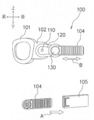
まず、本実施形態に係るレンズ体及びその取付機構の全体について説明する。図1は、本実施形態に係るレンズ体及びその取付機構の全体の斜視図である。図1において、本実施形態に係るレンズ体100は、レンズを支持する枠部材101と、枠部材101の左右端部から左右方向と直交する後方に延びる側枠部材102とから成り、側枠部材102と一端側が第1の部材110で軸支された角度調整アーム120と、角度調整アーム120の他端側と一端側が第2の部材130で軸支されたラチェットステー104と、ラチェットステー104を顔の前後方向に進退させて支持するラチェットステーホルダー105とから構成される。ラチェットステーホルダー105には、例えば、ラチェットステー104を進退可能に挿脱するための凹部が形成されている。
First, the lens body according to the present embodiment and the entire attachment mechanism thereof will be described. FIG. 1 is a perspective view of the entire lens body and its attachment mechanism according to the present embodiment. In FIG. 1, the lens body 100 according to the present embodiment includes a frame member 101 for supporting the lens, and a side frame member 102 extending rearward from the left and right ends of the frame member 101 orthogonal to the left and right direction. 102, an angle adjusting arm 120 pivotally supported by the first member 110 at one end side, a ratchet stay 104 pivotally supported by the second member 130 at the other end side and one end side of the angle adjusting arm 120, and a ratchet stay 104 It consists of a ratchet stay holder 105 supported by advancing and retracting in the front and back direction of the face. The ratchet stay holder 105 is formed with, for example, a recess for inserting and removing the ratchet stay 104 so as to be able to move forward and backward.
レンズ体100の顔の上下方向(レンズの仰俯角)における角度調整は、第1の部材110の軸を中心としてレンズ体100を顔の上下方向に傾動させること、第2の部材130の軸を中心としてレンズ体100を顔の上下方向に傾動させること、及び第1の部材110の軸と第2の部材130の軸とを中心としてレンズ体100を顔の上下方向に傾動させることにより行うことができる。また、レンズ体100の顔の上下方向における位置調整は、第2の部材130の軸を中心としてレンズ体100を顔の上下方向に移動させた後、第1の部材110の軸を中心として角度調整することで達成される。さらに、レンズ体100の顔の前後方向における位置調整は、ラチェットステー104をラチェットステーホルダー105に挿脱することにより行うことができる。なお、図1においては、レンズ体100の左側面側について説明を行っているが、右側面側も左側面側と同様な構成となっている。
The angle adjustment in the vertical direction of the face of the lens body 100 (the supination angle of the lens) tilts the lens body 100 in the vertical direction of the face centering on the axis of the first member 110, the axis of the second member 130 The lens body 100 is tilted in the vertical direction of the face as the center, and the lens body 100 is tilted in the vertical direction of the face around the axis of the first member 110 and the axis of the second member 130. Can. In the position adjustment of the face of the lens body 100 in the vertical direction, after the lens body 100 is moved in the vertical direction of the face about the axis of the second member 130, the angle about the axis of the first member 110 is an angle. Achieved by adjusting. Further, position adjustment of the lens body 100 in the front-rear direction of the face can be performed by inserting and removing the ratchet stay 104 into and from the ratchet stay holder 105. Although the left side of the lens body 100 is described in FIG. 1, the right side is configured the same as the left side.
また、図1においては、側枠部材102の左右方向外側の面と角度調整アーム120の一端側の左右方向内側の面とを重ね合わせること、及び角度調整アーム120の他端側の左右方向外側の面とラチェットステー104の一端側の左右方向内側の面とを重ね合わせることを具体例に挙げて説明を行っているが、側枠部材102と角度調整アーム120との何れの面同士を重ね合わせるか、及び角度調整アーム120とラチェットステー104との何れの面同士を重ね合わせるかは、任意の形態を採り得ることは勿論である。
Further, in FIG. 1, the surface on the outer side in the lateral direction of the side frame member 102 and the surface on the inner side in the lateral direction on one end side of the angle adjustment arm 120 are overlapped. In the specific example, the overlapping of the side surface of the side frame member 102 and the angle adjusting arm 120 is overlapped. Of course, it is possible to take any form as to whether to align and which surfaces of the angle adjustment arm 120 and the ratchet stay 104 to overlap with each other.
次に、本実施形態に係るレンズ体及びその取付機構における要部、要部において第2の部材を用いてレンズ体の上下方向の位置を調整する場合、及び要部において第1の部材を用いてレンズ体の上下方向の角度を調整する場合について説明する。
図2Aは、本実施形態に係るレンズ体及びその取付機構における要部を示す左側面図であり、図2Bは、本実施形態に係るレンズ体及びその取付機構における要部を示す左側面図において第2の部材を用いてレンズ体の上下方向の位置を調整する場合について説明する図であり、図2Cは、本実施形態に係るレンズ体及びその取付機構における要部を示す左側面図において第1の部材を用いてレンズ体の上下方向の角度を調整する場合について説明する図である。 Next, when adjusting the position in the vertical direction of the lens body using the second member in the main part and the main part of the lens body and its attachment mechanism according to the present embodiment, and using the first member in the main part The case of adjusting the vertical angle of the lens body will be described.
FIG. 2A is a left side view showing essential parts of the lens body and its attachment mechanism according to the present embodiment, and FIG. 2B is a left side view showing essential parts of the lens body and its attachment mechanism according to the present embodiment. It is a figure explaining the case where the position of the up-and-down direction of a lens object is adjusted using the 2nd member, and Drawing 2C is the left side figure showing the lens part concerning this embodiment, and the principal part in the attachment mechanism It is a figure explaining the case where the angle of the up-and-down direction of a lens object is adjusted using the member of 1. FIG.
図2Aに示すように側枠部材102と角度調整アーム120の一端側とが第1の部材110を介して、左右方向から見て側枠部材102と角度調整アーム120とが互いに回動するよう軸支される。そして、角度調整アーム120の他端側とラチェットステー104の一端側とが第2の部材130を介して、左右方向から見て角度調整アーム120とラチェットステー104とが互いに回動するよう軸支される。そして、ラチェットステー104は、例えば、中空状に形成されたラチェットステーホルダー105に図2Aの矢印A方向に挿入される。そして、ラチェットステー104は、ラチェットステーホルダー105に対して双方向矢印Bで示す双方向に伸縮可能に構成されている。
As shown in FIG. 2A, the side frame member 102 and the one end side of the angle adjustment arm 120 rotate through the first member 110 so that the side frame member 102 and the angle adjustment arm 120 rotate relative to each other as viewed from the left and right. Supported. The other end of the angle adjustment arm 120 and the one end of the ratchet stay 104 are pivotally supported by the second member 130 so that the angle adjustment arm 120 and the ratchet stay 104 rotate relative to each other when viewed from the left and right. Be done. Then, the ratchet stay 104 is inserted into, for example, a hollow hollow ratchet stay holder 105 in the direction of arrow A in FIG. 2A. The ratchet stay 104 is configured to be extensible and retractable in both directions shown by the bidirectional arrow B with respect to the ratchet stay holder 105.
図2Bでは、第2の部材130を支点として角度調整アーム120を着用者の顔の上方向に傾けることにより角度調整アーム120の一端側に連結されたレンズ体100を顔の上方向に位置移動している。なお、双方向矢印Cで示すように顔の下方向に位置移動することも可能である。
In FIG. 2B, the lens body 100 coupled to one end of the angle adjustment arm 120 is moved in the upward direction of the face by tilting the angle adjustment arm 120 in the upper direction of the wearer's face with the second member 130 as a fulcrum. doing. In addition, it is also possible to move in the downward direction of the face as shown by the double arrow C.
図2Cでは、第2の部材130を支点として角度調整アーム120を顔の下方向に傾け、第1の部材110を支点としてレンズ体100を顔の上方向に傾けることによりレンズ体100を顔に近付け、そして、上方向に角度調整している。なお、双方向矢印Dで示すように顔の下方向に角度調整することも可能である。
In FIG. 2C, the lens body 100 is turned to the face by inclining the angle adjusting arm 120 downward in the face with the second member 130 as a fulcrum and inclining the lens body 100 in the upward direction of the face with the first member 110 as a fulcrum. Close and adjust the angle upward. In addition, it is also possible to adjust the angle in the downward direction of the face as shown by the double arrow D.
なお、図示していないが、レンズ体100の側枠部材102と角度調整アーム120とを平行状態に維持したまま、第2の部材130を支点として角度調整アーム120を傾け、レンズ体100を顔の上下方向に移動することも可能である。また、図2A~図2Cにおいては、レンズ体100の左側面側について説明を行っているが、右側面側も左側面側と同様な構成となっている。
Although not shown, the angle adjusting arm 120 is inclined with the second member 130 as a fulcrum while maintaining the side frame member 102 of the lens body 100 and the angle adjusting arm 120 in parallel, and the lens body 100 is It is also possible to move vertically. Further, in FIGS. 2A to 2C, although the left side of the lens body 100 is described, the right side is the same as the left side.
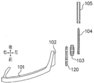
次に、本実施形態に係るレンズ体及びその取付機構における要部について説明する。図3Aは、本実施形態に係るレンズ体及びその取付機構における要部を示す上面図であり、図3Bは、本実施形態に係るレンズ体及びその取付機構における要部を示す正面図、図3Cは、本実施形態に係るレンズ体及びその取付機構における要部を示す左側面図である。
Next, the main parts of the lens body and the mounting mechanism thereof according to the present embodiment will be described. FIG. 3A is a top view showing the main parts of the lens body and its attachment mechanism according to the present embodiment, and FIG. 3B is a front view showing the main parts of the lens body and its attachment mechanism according to the present embodiment; These are left side views which show the principal part in the lens body which concerns on this embodiment, and its attachment mechanism.
図3A、図3B、図3Cに示すように、レンズ体100の左側の側枠部材102と角度調整アーム120の一端側とが連結される。そして、角度調整アーム120の他端側とラチェットステー104の一端側とがサイズ調整部材の一例であるサイズ調整ワッシャー103を介して連結される。そして、ラチェットステー104の他端側が中空状のラチェットステーホルダー105に挿入される。
As shown in FIGS. 3A, 3B, and 3C, the side frame member 102 on the left side of the lens body 100 and one end side of the angle adjustment arm 120 are connected. Then, the other end side of the angle adjustment arm 120 and one end side of the ratchet stay 104 are connected via a size adjustment washer 103 which is an example of a size adjustment member. Then, the other end side of the ratchet stay 104 is inserted into the hollow ratchet stay holder 105.
なお、後述するように、サイズ調整ワッシャー103は、レンズ体100を装着する着用者の顔の横幅サイズに応じて、側枠部材102とラチェットステー104との間の距離を調整するものである。また、図3A、図3B、図3Cにおいては、サイズ調整ワッシャー103が、角度調整アーム120とラチェットステー104との間に挿入されている例について説明しているが、サイズ調整ワッシャー103は、側枠部材102と角度調整アーム120との間に挿入されていても良いし、側枠部材102と角度調整アーム120との間、及び角度調整アーム120とラチェットステー104との間の両方に挿入されていても良い。また、図3A、図3B、図3Cにおいては、レンズ体100の左側面側について説明を行っているが、右側面側においても左側面側と同様な構成となっている。
As described later, the size adjustment washer 103 adjusts the distance between the side frame member 102 and the ratchet stay 104 according to the width size of the face of the wearer wearing the lens body 100. Moreover, although the example in which the size adjustment washer 103 is inserted between the angle adjustment arm 120 and the ratchet stay 104 is demonstrated in FIG. 3A, FIG. 3B and FIG. 3C, the size adjustment washer 103 is a side It may be inserted between the frame member 102 and the angle adjusting arm 120, or may be inserted both between the side frame member 102 and the angle adjusting arm 120 and between the angle adjusting arm 120 and the ratchet stay 104. May be Moreover, although the left side of the lens body 100 is described in FIGS. 3A, 3B, and 3C, the right side is configured similarly to the left side.
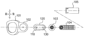
次に、本実施形態に係るレンズ体及びその取付機構においてサイズ調整部材を取り付ける例、及び角度保持部材を取り付ける例について説明する。図4は、本実施形態に係るレンズ体及びその取付機構においてサイズ調整部材の一例であるサイズ調整ワッシャーを取り付ける例、及び角度保持部材の一例である、滑り止め機能及び角度調整機能を有するワッシャーを取り付ける例について説明する上面図である。
Next, an example of attaching the size adjustment member in the lens body and its attachment mechanism according to the present embodiment, and an example of attaching the angle holding member will be described. FIG. 4 shows an example of attaching a size adjustment washer which is an example of a size adjustment member in the lens body and its attachment mechanism according to the embodiment, and a washer having a non-slip function and an angle adjustment function as an example of an angle holding member. It is a top view explaining the example of attachment.
まず、レンズ体100を装着する着用者の顔の横幅サイズに応じて、側枠部材102とラチェットステー104との間の距離を調整する方法について説明する。図4において、角度調整アーム120の他端側とラチェットステー104の一端側とがサイズ調整ワッシャー103を介して連結される。サイズ調整ワッシャー103は、レンズ体100を装着する人間の顔の横幅サイズに応じて、側枠部材102とラチェットステー104との間の距離を調整する機能を有するものである。図4では、レンズ体100の装着者の顔の横幅サイズに応じて、Sサイズ、Mサイズ、Lサイズ、及びXLサイズを例示しているが、これ等のサイズに限定されないことは勿論である。
First, a method of adjusting the distance between the side frame member 102 and the ratchet stay 104 according to the width size of the face of the wearer wearing the lens body 100 will be described. In FIG. 4, the other end side of the angle adjustment arm 120 and one end side of the ratchet stay 104 are connected via the size adjustment washer 103. The size adjustment washer 103 has a function of adjusting the distance between the side frame member 102 and the ratchet stay 104 in accordance with the width size of the human face to which the lens body 100 is attached. Although S size, M size, L size, and XL size are illustrated in FIG. 4 according to the width size of the face of the wearer of the lens body 100, it is a matter of course that the present invention is not limited to these sizes. .
また、図4に示すように、角度調整アーム120には、レンズ体100の着用者の顔の上下方向の角度を調整する機能に加え、ある角度に調整された場合、その角度を維持するよう滑り止め機能を有する角度保持部材の一例であるワッシャー106が取り付けられるようにしても良い。これにより、レンズ体100の位置(角度)の精度が要求されるあらゆる分野において用いられるレンズ体100に対して適用することができる。
Further, as shown in FIG. 4, in addition to the function of adjusting the vertical angle of the face of the wearer of the lens body 100, the angle adjustment arm 120 maintains the angle when adjusted to a certain angle. A washer 106, which is an example of an angle holding member having a non-slip function, may be attached. Thereby, the present invention can be applied to the lens body 100 used in any field where the accuracy of the position (angle) of the lens body 100 is required.
なお、図4においては、すべり止め機能を有するワッシャー106が、角度調整アーム120とラチェットステー104との間に挿入されている例について説明しているが、すべり止め機能を有するワッシャー106は、側枠部材102と角度調整アーム120との間に挿入されていても良いし、側枠部材102と角度調整アーム120との間、及び角度調整アーム120とラチェットステー104との間の両方に挿入されていても良い。また、図4においては、レンズ体100の左側面側について説明を行っているが、右側面側においても左側面側と同様な構成となっている。
In addition, although the example in which the washer 106 which has a non-slip function is inserted between the angle adjustment arm 120 and the ratchet stay 104 in FIG. 4 is demonstrated, the washer 106 which has a non-slip function is It may be inserted between the frame member 102 and the angle adjusting arm 120, or may be inserted both between the side frame member 102 and the angle adjusting arm 120 and between the angle adjusting arm 120 and the ratchet stay 104. May be Further, although the left side of the lens body 100 is described in FIG. 4, the right side is configured similarly to the left side.
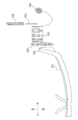
次に、本実施形態に係るレンズ体及びその取付機構をヘルメットに装着した場合について説明する。図5は、本実施形態に係るレンズ体及びそ取付機構をヘルメットに装着した一例の左側面図である。また、図6は、本実施形態に係るレンズ体及びその取付機構をヘルメットに装着した図5のA-A断面図である。
Next, the case where the lens body and the attachment mechanism thereof according to the present embodiment are attached to a helmet will be described. FIG. 5 is a left side view of an example in which the lens body and its attachment mechanism according to the present embodiment are mounted on a helmet. 6 is a cross-sectional view taken along the line AA in FIG. 5 in which the lens body and the attachment mechanism thereof according to the present embodiment are mounted on a helmet.
図5、図6に示すように、ラチェットステーホルダー105は、ヘルメット1の内側の着用者の顔に近い場所に形成された凹部3に取り付けられる。なお、図6においては、ラチェットステーホルダー105が、ヘルメット1の内側に固定された、マスクライナー2に形成された凹部3に装着されている例を挙げて説明を行っているが、ヘルメットの内側に固定された何れの箇所に凹部3を設けても良いことは勿論である。
As shown in FIG. 5 and FIG. 6, the ratchet stay holder 105 is attached to a recess 3 formed at a position near the wearer's face inside the helmet 1. In addition, in FIG. 6, although the ratchet stay holder 105 mentions the example currently mounted | worn with the recessed part 3 formed in the mask liner 2 fixed to the inner side of the helmet 1, it demonstrates, but the inner side of a helmet It goes without saying that the recess 3 may be provided at any place fixed to.
以上説明したように、本実施形態によれば、側枠部材102と角度調整アーム120との間のなす角度、及び、角度調整アーム120とラチェットステー104との間のなす角度を変えることで、レンズ体100の位置を広範囲に調整することができる。要するに、レンズ体100の上下方向の位置及び傾きを、複数箇所で軸支された支点を用いることによって可変可能にしているのである。したがって、レンズ体100の位置を、より着用者にフィットするようにきめ細かくフレキシブルに調整することができるといった従来技術では得ることができない効果を有するものである。
As described above, according to the present embodiment, by changing the angle between the side frame member 102 and the angle adjustment arm 120 and the angle between the angle adjustment arm 120 and the ratchet stay 104, The position of the lens body 100 can be adjusted over a wide range. In short, the position and the inclination of the lens body 100 in the vertical direction can be made variable by using fulcrums supported at a plurality of places. Therefore, it has an effect which can not be obtained by the prior art that the position of the lens body 100 can be finely and flexibly adjusted so as to fit the wearer more.
さらに、着用者にフィットする角度が一旦定まると、その角度を維持するための滑り止め機能を有するワッシャーが取り付けられているので、長時間、着用者にフィットする状態を維持することができる。
Furthermore, once the angle for fitting to the wearer is determined, a washer having a non-slip function for maintaining the angle is attached, so that the state for fitting to the wearer can be maintained for a long time.
したがって、自転車やバイク等の二輪車を使った競技のレーサーや、F1等のレーシングドライバーが、ヘルメットを着用した状態で本発明のレンズ体の取付機構を搭載したレンズ体を装着することにより、汗や振動等の影響をほとんど受けることなく、最適なフィット感を維持することができ、競技に集中することができる。
Therefore, by wearing a lens body equipped with the lens body mounting mechanism of the present invention while wearing a helmet, a racer of a competition using a two-wheeler such as a bicycle or a motorcycle or a racing driver such as F1 wears sweat or An optimal fit can be maintained with little influence from vibrations and the like, and it is possible to concentrate on the competition.
また、運転中に必要な計器類の数値情報や後方視界情報等の各種情報を、ヘルメットを被ったライダーが着用する眼鏡のレンズの所定の領域に表示する技術にも本発明を応用できる。要するに、レンズ体を映像表示装置として用いるのである。そして、このような情報は、運転中のライダーの視界を遮ることなく視認可能な位置に的確に表示することが求められている。それゆえ、運転中に眼鏡の位置がずれるということは安全性に重大な影響を及ぼしかねない。
Further, the present invention can be applied to a technology for displaying various information such as numerical information of instruments and rear visibility information necessary during driving on a predetermined area of a lens of glasses worn by a rider wearing a helmet. In short, the lens body is used as an image display device. Then, such information is required to be accurately displayed at a position that can be viewed without blocking the view of the rider while driving. Therefore, shifting the position of the glasses while driving can have a significant impact on safety.
このような状況下、本発明のレンズ体とその取付機構を、ヘルメットを被ったライダーが装着することにより、ライダーに最もフィットする位置(角度)にレンズ体が調整されることになるため、運転中にレンズ体の位置がずれるといった状況は皆無となる。したがって、各種情報をレンズ体の適切な位置に表示すると共に、ライダーの視界を良好に確保することができるので、安全性が十分担保されるという効果が得られるのである。
Under such circumstances, the lens body of the present invention and the mounting mechanism thereof are worn by a rider wearing a helmet, so that the lens body is adjusted to a position (angle) that best fits the rider. There is no situation in which the position of the lens body is shifted. Therefore, since various information can be displayed at an appropriate position of the lens body and the rider's view can be well secured, the effect of sufficiently securing safety can be obtained.
以上説明したように、本発明は、レンズ体をヘルメットに取り付ける取付機構に関するものである。具体的には、レンズ体100のレンズを支持する枠部材101の左右端部から後方に延びる側枠部材102の前後方向に略平行な一方の面と、レンズの仰俯角を調整する角度調整アーム120の一端側の前後方向に略平行な上記一方の面と対向する面とを重ね合わせる。そして、第1の部材110を用いて、左右方向から見て側枠部材102と角度調整アーム120とが互いに回動するよう軸支することとしている。
As described above, the present invention relates to an attachment mechanism for attaching a lens body to a helmet. Specifically, an angle adjustment arm for adjusting the elevation angle of the lens and one surface substantially parallel to the front-rear direction of the side frame member 102 extending rearward from the left and right ends of the frame member 101 for supporting the lens of the lens body 100 The one surface substantially parallel to the front-rear direction on the one end side of 120 and the surface facing the one surface are superimposed. Then, by using the first member 110, the side frame member 102 and the angle adjustment arm 120 are pivotally supported so as to rotate relative to each other as viewed in the left-right direction.
また、角度調整アーム120の他端側の前後方向に略平行な一方の面と、レンズの前後方向における位置を調整するラチェットステー104の一端側の前後方向に略平行な上記一方の面と対向する面とを重ね合わせる。そして、第2の部材130を用いて、左右方向から見て角度調整アーム120とラチェットステー104とが互いに回動するよう軸支することとしている。
Further, one surface substantially parallel to the front-rear direction of the other end side of the angle adjustment arm 120 and the one surface substantially parallel to the front-rear direction one end side of the ratchet stay 104 for adjusting the position of the lens in the front-rear direction Overlap with the surface to be Then, using the second member 130, the angle adjustment arm 120 and the ratchet stay 104 are pivotally supported so as to rotate relative to each other as viewed in the left-right direction.
さらに、ラチェットステー104の他端側を前後方向に伸縮可能に保持するラチェットステーホルダー105を有している。これにより、眼鏡着用者の様々な顔の長さ及び目の位置に適合させることにより眼鏡の視界を確保すると共に、位置及び角度を微細に調整することにより眼鏡の最適なフィット感を得ることが可能なレンズ体の取付機構が得られるのである。
Furthermore, the ratchet stay holder 105 holds the other end side of the ratchet stay 104 so as to be extensible and contractible in the front-rear direction. This ensures the visibility of the glasses by adapting them to the different face lengths and positions of the glasses wearer, and obtains the best fit of the glasses by finely adjusting the position and angle. A possible lens body attachment mechanism is obtained.
以上、これまで本発明の実施形態について説明してきたが、本発明の実施形態は上述した実施形態に限定されるものではない。すなわち、他の実施形態、追加、変更、削除等、当業者が想到することができる範囲内で変更することができ、何れの態様においても本発明の作用効果を奏する限り、本発明の範囲に含まれるものである。
Although the embodiments of the present invention have been described above, the embodiments of the present invention are not limited to the above-described embodiments. That is, other embodiments, additions, modifications, deletions, etc. can be modified within the scope of those skilled in the art, and any modifications can be made within the scope of the present invention as long as the effects of the present invention can be exhibited. It is included.
1 ヘルメット
2 マスクライナー
3 凹部
100 レンズ体
101 枠部材
102 側枠部材
103 サイズ調整ワッシャー
104 ラチェットステー
105 ラチェットステーホルダー
106 ワッシャー
110 第1の部材
120 角度調整アーム
130 第2の部材 DESCRIPTION OF SYMBOLS 1helmet 2 mask liner 3 recessed part 100 lens body 101 frame member 102 side frame member 103 size adjustment washer 104 ratchet stay 105 ratchet stay holder 106 washer 110 1st member 120 angle adjustment arm 130 2nd member
2 マスクライナー
3 凹部
100 レンズ体
101 枠部材
102 側枠部材
103 サイズ調整ワッシャー
104 ラチェットステー
105 ラチェットステーホルダー
106 ワッシャー
110 第1の部材
120 角度調整アーム
130 第2の部材 DESCRIPTION OF SYMBOLS 1
Claims (4)
- ヘルメット着用者の眼前にレンズ体を保持するように取り付けるためのレンズ体の取付機構であって、
一対のレンズを支持する枠部材と、その左右端部からレンズの後方へ延びる側枠部材とから成るレンズ体と、
前記側枠部材に連結して前記レンズ体の仰俯角を調整する角度調整部材と、
前記側枠部材と前記角度調整部材とが互いに回動するよう軸支する第1の部材と、
前記レンズ体の水平方向における位置を調整する位置調整部材と、
前記角度調整部材と前記位置調整部材とが互いに回動するよう軸支する第2の部材と、
前記位置調整部材のヘルメット側端部を水平方向に伸縮可能に保持する位置調整保持部材と、
を含むことを特徴とするレンズ体の取付機構。 A lens body attachment mechanism for attaching a lens body to hold the lens body in front of a helmet wearer's eye,
A lens body comprising a frame member for supporting a pair of lenses, and a side frame member extending from the left and right ends thereof to the rear of the lens;
An angle adjustment member connected to the side frame member to adjust the elevation angle of the lens body;
A first member pivotally supporting the side frame member and the angle adjusting member so as to rotate relative to each other;
A position adjustment member that adjusts the position of the lens body in the horizontal direction;
A second member pivotally supporting the angle adjustment member and the position adjustment member so as to rotate relative to each other;
A position adjustment holding member that holds the helmet side end of the position adjusting member so as to be extensible and contractible in the horizontal direction;
And a lens body attachment mechanism characterized by including: - 前記側枠部材の前記水平方向に略平行な第1の面と前記第1の面と対向する面との間、及び/又は前記角度調整部材の前記水平方向に略平行な第2の面と前記第2の面と対向する面との間に挿入され、前記ヘルメット着用者の顔の左右方向の幅を調整するサイズ調整部材をさらに含むことを特徴とする請求項1に記載のレンズ体の取付機構。 Between a first surface substantially parallel to the horizontal direction of the side frame member and a surface opposite to the first surface, and / or a second surface substantially parallel to the horizontal direction of the angle adjusting member The lens body according to claim 1, further comprising a size adjusting member inserted between the second surface and the opposite surface to adjust the width of the helmet wearer's face in the left-right direction. Mounting mechanism.
- 前記第1の面と前記第1の面と対向する面との間、及び/又は前記第2の面と前記第2の面と対向する面との間に挿入され、前記左右方向から見た前記側枠部材と前記角度調整部材との間のなす角度、及び/又は前記左右方向から見た前記角度調整部材と前記位置調整部材との間のなす角度を保持する角度保持部材をさらに含むことを特徴とする請求項2に記載のレンズ体の取付機構。 It is inserted between the first surface and the surface opposite to the first surface and / or between the second surface and the surface opposite to the second surface, as viewed from the left-right direction And an angle holding member for holding an angle between the side frame member and the angle adjusting member, and / or an angle between the angle adjusting member and the position adjusting member when viewed from the left-right direction. The attachment mechanism of the lens body of Claim 2 characterized by the above-mentioned.
- 前記レンズ体は映像表示装置であることを特徴とする請求項1から3の何れか1項に記載のレンズ体の取付機構。 The lens body mounting mechanism according to any one of claims 1 to 3, wherein the lens body is an image display device.
Priority Applications (2)
| Application Number | Priority Date | Filing Date | Title |
|---|---|---|---|
| US16/306,915 US10772374B2 (en) | 2016-06-08 | 2017-04-05 | Lens unit attachment mechanism |
| EP17809950.3A EP3469940B1 (en) | 2016-06-08 | 2017-04-05 | Lens body mounting mechanism |
Applications Claiming Priority (2)
| Application Number | Priority Date | Filing Date | Title |
|---|---|---|---|
| JP2016-114206 | 2016-06-08 | ||
| JP2016114206A JP6617078B2 (en) | 2016-06-08 | 2016-06-08 | Lens body mounting mechanism |
Publications (1)
| Publication Number | Publication Date |
|---|---|
| WO2017212767A1 true WO2017212767A1 (en) | 2017-12-14 |
Family
ID=60578574
Family Applications (1)
| Application Number | Title | Priority Date | Filing Date |
|---|---|---|---|
| PCT/JP2017/014252 WO2017212767A1 (en) | 2016-06-08 | 2017-04-05 | Lens body mounting mechanism |
Country Status (4)
| Country | Link |
|---|---|
| US (1) | US10772374B2 (en) |
| EP (1) | EP3469940B1 (en) |
| JP (1) | JP6617078B2 (en) |
| WO (1) | WO2017212767A1 (en) |
Cited By (1)
| Publication number | Priority date | Publication date | Assignee | Title |
|---|---|---|---|---|
| WO2020106665A1 (en) * | 2018-11-20 | 2020-05-28 | Facebook Technologies, Llc | Head-mounted display with unobstructed peripheral viewing |
Families Citing this family (7)
| Publication number | Priority date | Publication date | Assignee | Title |
|---|---|---|---|---|
| JP6568887B2 (en) * | 2017-03-14 | 2019-08-28 | 本田技研工業株式会社 | Information display device |
| US10959478B2 (en) * | 2017-09-22 | 2021-03-30 | Hummingbird Sports, Llc | Eye protection orientation system |
| CN109828374A (en) * | 2019-03-27 | 2019-05-31 | 深圳市忻毅科技有限公司 | A kind of intelligent glasses of left and right adjusting |
| CN109782449A (en) * | 2019-03-27 | 2019-05-21 | 深圳市忻毅科技有限公司 | It is a kind of can front and back adjust intelligent glasses |
| US11213089B2 (en) * | 2019-06-04 | 2022-01-04 | Msa Technology, Llc | Protective helmet with face protection shield and linkage mechanism |
| CN112612140B (en) * | 2020-12-29 | 2022-10-18 | 重庆蓝岸科技股份有限公司 | Noiseless two-way ratchet structure |
| AU2022215630A1 (en) | 2021-02-08 | 2023-07-27 | Milwaukee Electric Tool Corporation | Hard hat face shield attachment system |
Citations (13)
| Publication number | Priority date | Publication date | Assignee | Title |
|---|---|---|---|---|
| US4544245A (en) | 1979-07-16 | 1985-10-01 | Mckesson Corporation | Adjustable safety spectacle |
| JPH0312218U (en) * | 1989-06-21 | 1991-02-07 | ||
| US5052054A (en) * | 1990-01-02 | 1991-10-01 | Birum Donald A | Cap structure with implement adapter |
| JPH04127221A (en) | 1990-09-18 | 1992-04-28 | Toshiba Corp | Mouse device |
| JPH07279939A (en) * | 1994-04-07 | 1995-10-27 | Asahi Glass Co Ltd | Washer |
| JPH11346336A (en) * | 1998-06-01 | 1999-12-14 | Fuji Electric Co Ltd | Eyeglass type head mount display device |
| JP2000178820A (en) | 1998-12-11 | 2000-06-27 | Wise Gear:Kk | Helmet |
| JP2000303244A (en) * | 1999-04-23 | 2000-10-31 | Tanizawa Seisakusho Ltd | Mounting tool for interior material of helmet |
| US20030071961A1 (en) * | 2001-10-12 | 2003-04-17 | John R. Schubert | Apparatus for positioning a magnifying lens |
| JP2005061449A (en) * | 2003-08-18 | 2005-03-10 | Shibao Tsukada | Fastener consisting of bolt and nut |
| US6892393B1 (en) * | 2003-12-29 | 2005-05-17 | Jack Provost | Safety helmet attachment and method for shielding eyes |
| JP2005309272A (en) * | 2004-04-26 | 2005-11-04 | Hiroshi Nakazawa | Free tilt angle type spectacles |
| WO2015059014A1 (en) | 2013-10-24 | 2015-04-30 | Pfanner Schutzbekleidung Gmbh | Protective glasses for fitting on a protective helmet, and protective helmet provided with the protective glassses |
Family Cites Families (5)
| Publication number | Priority date | Publication date | Assignee | Title |
|---|---|---|---|---|
| JPH04127221U (en) | 1991-05-09 | 1992-11-19 | 株式会社アライヘルメツト | helmet |
| US5230101A (en) * | 1991-09-27 | 1993-07-27 | Gentex Corporation | Dual visor operating mechanism |
| WO2008025083A1 (en) * | 2006-08-31 | 2008-03-06 | David John Springer | Hard hat with attached safety glasses |
| FR2938738B1 (en) * | 2008-11-25 | 2011-01-14 | Thales Sa | HELMET HAVING A MOBILE VISOR WITH A VERTICAL ROTATION AXIS. |
| GB2504323B (en) * | 2012-07-25 | 2015-10-14 | Andrew Greene | A modified helmet |
-
2016
- 2016-06-08 JP JP2016114206A patent/JP6617078B2/en active Active
-
2017
- 2017-04-05 WO PCT/JP2017/014252 patent/WO2017212767A1/en unknown
- 2017-04-05 US US16/306,915 patent/US10772374B2/en active Active
- 2017-04-05 EP EP17809950.3A patent/EP3469940B1/en active Active
Patent Citations (13)
| Publication number | Priority date | Publication date | Assignee | Title |
|---|---|---|---|---|
| US4544245A (en) | 1979-07-16 | 1985-10-01 | Mckesson Corporation | Adjustable safety spectacle |
| JPH0312218U (en) * | 1989-06-21 | 1991-02-07 | ||
| US5052054A (en) * | 1990-01-02 | 1991-10-01 | Birum Donald A | Cap structure with implement adapter |
| JPH04127221A (en) | 1990-09-18 | 1992-04-28 | Toshiba Corp | Mouse device |
| JPH07279939A (en) * | 1994-04-07 | 1995-10-27 | Asahi Glass Co Ltd | Washer |
| JPH11346336A (en) * | 1998-06-01 | 1999-12-14 | Fuji Electric Co Ltd | Eyeglass type head mount display device |
| JP2000178820A (en) | 1998-12-11 | 2000-06-27 | Wise Gear:Kk | Helmet |
| JP2000303244A (en) * | 1999-04-23 | 2000-10-31 | Tanizawa Seisakusho Ltd | Mounting tool for interior material of helmet |
| US20030071961A1 (en) * | 2001-10-12 | 2003-04-17 | John R. Schubert | Apparatus for positioning a magnifying lens |
| JP2005061449A (en) * | 2003-08-18 | 2005-03-10 | Shibao Tsukada | Fastener consisting of bolt and nut |
| US6892393B1 (en) * | 2003-12-29 | 2005-05-17 | Jack Provost | Safety helmet attachment and method for shielding eyes |
| JP2005309272A (en) * | 2004-04-26 | 2005-11-04 | Hiroshi Nakazawa | Free tilt angle type spectacles |
| WO2015059014A1 (en) | 2013-10-24 | 2015-04-30 | Pfanner Schutzbekleidung Gmbh | Protective glasses for fitting on a protective helmet, and protective helmet provided with the protective glassses |
Cited By (1)
| Publication number | Priority date | Publication date | Assignee | Title |
|---|---|---|---|---|
| WO2020106665A1 (en) * | 2018-11-20 | 2020-05-28 | Facebook Technologies, Llc | Head-mounted display with unobstructed peripheral viewing |
Also Published As
| Publication number | Publication date |
|---|---|
| JP6617078B2 (en) | 2019-12-04 |
| US20190133236A1 (en) | 2019-05-09 |
| US10772374B2 (en) | 2020-09-15 |
| JP2017218696A (en) | 2017-12-14 |
| EP3469940A4 (en) | 2020-01-01 |
| EP3469940B1 (en) | 2021-02-24 |
| EP3469940A1 (en) | 2019-04-17 |
Similar Documents
| Publication | Publication Date | Title |
|---|---|---|
| WO2017212767A1 (en) | Lens body mounting mechanism | |
| JP2017526008A (en) | Headset with versatile eye orientation adjustment system | |
| JP2023133402A (en) | Eyeglass lens piece configured for both forward and rearward viewing | |
| WO2017110858A1 (en) | Bifocal glasses-shaped frame | |
| KR102196106B1 (en) | Perspective two-way glasses frame | |
| JP5223687B2 (en) | Stereoscopic glasses | |
| JP6268247B1 (en) | Peripheral glasses frame | |
| JP2013214910A (en) | Head-mounted display device | |
| JP3174805U (en) | Glasses nose pads | |
| WO2007148650A1 (en) | Spectacles set | |
| JP6407793B2 (en) | Head-mounted display device | |
| JP2009247775A (en) | Optometric glasses | |
| JP4626072B2 (en) | Video observation device | |
| JP2007286210A (en) | Spectacles attachable/detachable type sunglasses | |
| JP4039905B2 (en) | Loupe mounting spectacle frame and loupe using the spectacle frame | |
| JP6076121B2 (en) | Eyeglass frames | |
| JP6276748B2 (en) | Peripheral glasses frame | |
| JP2016151752A (en) | Spectacles | |
| JP3210521U (en) | Additional glasses for clear vision | |
| JP2012239689A (en) | Optometric test frame | |
| JP6782983B2 (en) | Glasses frame | |
| US20220244549A1 (en) | Attachment and head-mounted display | |
| JP6170993B2 (en) | Peripheral glasses frame | |
| CN212488721U (en) | Motorcycle helmet with myopia glasses | |
| KR20080102636A (en) | Clip integrated sunglass |
Legal Events
| Date | Code | Title | Description |
|---|---|---|---|
| 121 | Ep: the epo has been informed by wipo that ep was designated in this application |
Ref document number: 17809950 Country of ref document: EP Kind code of ref document: A1 |
|
| NENP | Non-entry into the national phase |
Ref country code: DE |
|
| ENP | Entry into the national phase |
Ref document number: 2017809950 Country of ref document: EP Effective date: 20190108 |