WO2017209409A1 - 구형 컨텐츠 편집 방법 및 이를 지원하는 전자 장치 - Google Patents
구형 컨텐츠 편집 방법 및 이를 지원하는 전자 장치 Download PDFInfo
- Publication number
- WO2017209409A1 WO2017209409A1 PCT/KR2017/004941 KR2017004941W WO2017209409A1 WO 2017209409 A1 WO2017209409 A1 WO 2017209409A1 KR 2017004941 W KR2017004941 W KR 2017004941W WO 2017209409 A1 WO2017209409 A1 WO 2017209409A1
- Authority
- WO
- WIPO (PCT)
- Prior art keywords
- image
- patch
- processor
- electronic device
- spherical content
- Prior art date
Links
- 238000000034 method Methods 0.000 title claims description 49
- 230000004044 response Effects 0.000 claims abstract description 42
- 230000008859 change Effects 0.000 claims description 9
- 238000004891 communication Methods 0.000 description 64
- 230000006870 function Effects 0.000 description 54
- 238000010586 diagram Methods 0.000 description 20
- 230000005540 biological transmission Effects 0.000 description 12
- 230000014509 gene expression Effects 0.000 description 8
- 230000008569 process Effects 0.000 description 6
- 238000006243 chemical reaction Methods 0.000 description 5
- 230000000694 effects Effects 0.000 description 4
- 238000012545 processing Methods 0.000 description 4
- 239000003086 colorant Substances 0.000 description 3
- 230000008676 import Effects 0.000 description 3
- 230000010267 cellular communication Effects 0.000 description 2
- 230000000295 complement effect Effects 0.000 description 2
- 239000004973 liquid crystal related substance Substances 0.000 description 2
- 230000003287 optical effect Effects 0.000 description 2
- 230000002093 peripheral effect Effects 0.000 description 2
- 238000012546 transfer Methods 0.000 description 2
- 230000009466 transformation Effects 0.000 description 2
- XLYOFNOQVPJJNP-UHFFFAOYSA-N water Substances O XLYOFNOQVPJJNP-UHFFFAOYSA-N 0.000 description 2
- 241000282836 Camelus dromedarius Species 0.000 description 1
- 241000283153 Cetacea Species 0.000 description 1
- WQZGKKKJIJFFOK-GASJEMHNSA-N Glucose Natural products OC[C@H]1OC(O)[C@H](O)[C@@H](O)[C@@H]1O WQZGKKKJIJFFOK-GASJEMHNSA-N 0.000 description 1
- 241001465754 Metazoa Species 0.000 description 1
- 241000270666 Testudines Species 0.000 description 1
- 230000009471 action Effects 0.000 description 1
- 230000004913 activation Effects 0.000 description 1
- 238000004458 analytical method Methods 0.000 description 1
- 238000002583 angiography Methods 0.000 description 1
- 238000003491 array Methods 0.000 description 1
- 238000013473 artificial intelligence Methods 0.000 description 1
- 230000003190 augmentative effect Effects 0.000 description 1
- 239000008280 blood Substances 0.000 description 1
- 210000004369 blood Anatomy 0.000 description 1
- 230000036772 blood pressure Effects 0.000 description 1
- 230000036760 body temperature Effects 0.000 description 1
- 238000004364 calculation method Methods 0.000 description 1
- 238000002591 computed tomography Methods 0.000 description 1
- 238000005034 decoration Methods 0.000 description 1
- 238000011161 development Methods 0.000 description 1
- 230000005611 electricity Effects 0.000 description 1
- -1 electricity Substances 0.000 description 1
- 238000005516 engineering process Methods 0.000 description 1
- 238000001914 filtration Methods 0.000 description 1
- 238000007667 floating Methods 0.000 description 1
- 239000008103 glucose Substances 0.000 description 1
- 238000003384 imaging method Methods 0.000 description 1
- 238000003780 insertion Methods 0.000 description 1
- 230000037431 insertion Effects 0.000 description 1
- 230000007774 longterm Effects 0.000 description 1
- 238000002595 magnetic resonance imaging Methods 0.000 description 1
- 238000010295 mobile communication Methods 0.000 description 1
- 238000012986 modification Methods 0.000 description 1
- 230000004048 modification Effects 0.000 description 1
- 230000003252 repetitive effect Effects 0.000 description 1
- 238000012958 reprocessing Methods 0.000 description 1
- 239000004984 smart glass Substances 0.000 description 1
- 239000007787 solid Substances 0.000 description 1
- 230000007704 transition Effects 0.000 description 1
- 238000013519 translation Methods 0.000 description 1
- 238000002604 ultrasonography Methods 0.000 description 1
- 238000005406 washing Methods 0.000 description 1
Images


Classifications
-
- G—PHYSICS
- G06—COMPUTING; CALCULATING OR COUNTING
- G06T—IMAGE DATA PROCESSING OR GENERATION, IN GENERAL
- G06T11/00—2D [Two Dimensional] image generation
- G06T11/60—Editing figures and text; Combining figures or text
-
- G06T3/12—
-
- H—ELECTRICITY
- H04—ELECTRIC COMMUNICATION TECHNIQUE
- H04N—PICTORIAL COMMUNICATION, e.g. TELEVISION
- H04N5/00—Details of television systems
- H04N5/222—Studio circuitry; Studio devices; Studio equipment
- H04N5/262—Studio circuits, e.g. for mixing, switching-over, change of character of image, other special effects ; Cameras specially adapted for the electronic generation of special effects
- H04N5/2628—Alteration of picture size, shape, position or orientation, e.g. zooming, rotation, rolling, perspective, translation
-
- G06T3/047—
-
- G—PHYSICS
- G06—COMPUTING; CALCULATING OR COUNTING
- G06T—IMAGE DATA PROCESSING OR GENERATION, IN GENERAL
- G06T7/00—Image analysis
- G06T7/90—Determination of colour characteristics
-
- G—PHYSICS
- G11—INFORMATION STORAGE
- G11B—INFORMATION STORAGE BASED ON RELATIVE MOVEMENT BETWEEN RECORD CARRIER AND TRANSDUCER
- G11B27/00—Editing; Indexing; Addressing; Timing or synchronising; Monitoring; Measuring tape travel
-
- G—PHYSICS
- G11—INFORMATION STORAGE
- G11B—INFORMATION STORAGE BASED ON RELATIVE MOVEMENT BETWEEN RECORD CARRIER AND TRANSDUCER
- G11B27/00—Editing; Indexing; Addressing; Timing or synchronising; Monitoring; Measuring tape travel
- G11B27/02—Editing, e.g. varying the order of information signals recorded on, or reproduced from, record carriers
- G11B27/031—Electronic editing of digitised analogue information signals, e.g. audio or video signals
-
- H—ELECTRICITY
- H04—ELECTRIC COMMUNICATION TECHNIQUE
- H04N—PICTORIAL COMMUNICATION, e.g. TELEVISION
- H04N23/00—Cameras or camera modules comprising electronic image sensors; Control thereof
- H04N23/45—Cameras or camera modules comprising electronic image sensors; Control thereof for generating image signals from two or more image sensors being of different type or operating in different modes, e.g. with a CMOS sensor for moving images in combination with a charge-coupled device [CCD] for still images
-
- H—ELECTRICITY
- H04—ELECTRIC COMMUNICATION TECHNIQUE
- H04N—PICTORIAL COMMUNICATION, e.g. TELEVISION
- H04N23/00—Cameras or camera modules comprising electronic image sensors; Control thereof
- H04N23/60—Control of cameras or camera modules
- H04N23/66—Remote control of cameras or camera parts, e.g. by remote control devices
- H04N23/661—Transmitting camera control signals through networks, e.g. control via the Internet
- H04N23/662—Transmitting camera control signals through networks, e.g. control via the Internet by using master/slave camera arrangements for affecting the control of camera image capture, e.g. placing the camera in a desirable condition to capture a desired image
-
- H—ELECTRICITY
- H04—ELECTRIC COMMUNICATION TECHNIQUE
- H04N—PICTORIAL COMMUNICATION, e.g. TELEVISION
- H04N23/00—Cameras or camera modules comprising electronic image sensors; Control thereof
- H04N23/60—Control of cameras or camera modules
- H04N23/698—Control of cameras or camera modules for achieving an enlarged field of view, e.g. panoramic image capture
-
- H—ELECTRICITY
- H04—ELECTRIC COMMUNICATION TECHNIQUE
- H04N—PICTORIAL COMMUNICATION, e.g. TELEVISION
- H04N21/00—Selective content distribution, e.g. interactive television or video on demand [VOD]
- H04N21/40—Client devices specifically adapted for the reception of or interaction with content, e.g. set-top-box [STB]; Operations thereof
- H04N21/45—Management operations performed by the client for facilitating the reception of or the interaction with the content or administrating data related to the end-user or to the client device itself, e.g. learning user preferences for recommending movies, resolving scheduling conflicts
- H04N21/454—Content or additional data filtering, e.g. blocking advertisements
- H04N21/4545—Input to filtering algorithms, e.g. filtering a region of the image
- H04N21/45455—Input to filtering algorithms, e.g. filtering a region of the image applied to a region of the image
-
- H—ELECTRICITY
- H04—ELECTRIC COMMUNICATION TECHNIQUE
- H04N—PICTORIAL COMMUNICATION, e.g. TELEVISION
- H04N21/00—Selective content distribution, e.g. interactive television or video on demand [VOD]
- H04N21/40—Client devices specifically adapted for the reception of or interaction with content, e.g. set-top-box [STB]; Operations thereof
- H04N21/47—End-user applications
- H04N21/472—End-user interface for requesting content, additional data or services; End-user interface for interacting with content, e.g. for content reservation or setting reminders, for requesting event notification, for manipulating displayed content
- H04N21/47205—End-user interface for requesting content, additional data or services; End-user interface for interacting with content, e.g. for content reservation or setting reminders, for requesting event notification, for manipulating displayed content for manipulating displayed content, e.g. interacting with MPEG-4 objects, editing locally
-
- H—ELECTRICITY
- H04—ELECTRIC COMMUNICATION TECHNIQUE
- H04N—PICTORIAL COMMUNICATION, e.g. TELEVISION
- H04N21/00—Selective content distribution, e.g. interactive television or video on demand [VOD]
- H04N21/80—Generation or processing of content or additional data by content creator independently of the distribution process; Content per se
- H04N21/81—Monomedia components thereof
- H04N21/816—Monomedia components thereof involving special video data, e.g 3D video
-
- H—ELECTRICITY
- H04—ELECTRIC COMMUNICATION TECHNIQUE
- H04N—PICTORIAL COMMUNICATION, e.g. TELEVISION
- H04N23/00—Cameras or camera modules comprising electronic image sensors; Control thereof
- H04N23/80—Camera processing pipelines; Components thereof
Definitions
- Various embodiments relate to image editing.
- the spherical content may include content capable of checking 360 degrees on the basis of the viewing point.
- the spherical content may be generated using, for example, a camera arranged back and forth and capable of capturing a predetermined angle or more.
- a structure, an apparatus, or a means (eg, a tripod, a hand, etc.) disposed at the bottom (or bottom) of the camera may be photographed.
- a structure image at the point where the camera substructure is disposed among the spherical contents is awkwardly expressed, such as crushed or partly cut off.
- Various embodiments of the present disclosure provide an old content editing method capable of easier and intuitive content editing and an electronic device supporting the same.
- an electronic device may include a memory for storing spherical content having at least a part of a spherical shape based on a center point, a display for outputting the spherical content, the memory, and a processor electrically connected to the display. And the processor may be configured to place a patch image designated at a center point of the spherical content.
- the spherical content editing method may include displaying a spherical content having at least a part of a spherical shape based on a center point, detecting a center point of the spherical content, and applying a patch image to a center point of the spherical content. It may include an operation for outputting.
- the various embodiments described above support editing of at least some areas of the spherical content more easily, intuitively, and in a manner that suits user preferences.
- FIG. 1 is a view showing an example of an old content management system according to an embodiment of the present invention.
- FIG. 2 is a diagram illustrating an example of an image capturing apparatus according to an exemplary embodiment of the present invention.
- FIG. 3 is a diagram illustrating an example of a terminal electronic device according to an embodiment of the present disclosure.
- FIG. 4 is a diagram illustrating an example of an old content editing method according to an embodiment of the present invention.
- FIG. 5 is a view showing an example of a method related to the operation of a patch function according to an embodiment of the present invention.
- FIG. 6 is a diagram illustrating an example of an old content editing screen interface according to an embodiment of the present invention.
- FIG. 7 is a diagram illustrating an example of a screen interface associated with applying a patch according to an embodiment of the present invention.
- FIG. 8 is a diagram illustrating an example of a patch image application screen according to an embodiment of the present invention.
- FIG. 9 is a diagram illustrating an example of a screen interface related to importing a patch according to an exemplary embodiment.
- FIG. 10 is a diagram illustrating an example of a screen interface related to patch item download according to an embodiment of the present invention.
- FIG. 11 is a diagram illustrating another example of an old content operation system according to another embodiment of the present invention.
- FIG. 12 is a diagram illustrating an example of a network environment associated with operation of a terminal electronic device according to an embodiment of the present disclosure.
- expressions such as “have”, “may have”, “include”, or “may contain” include the presence of a corresponding feature (e.g., numerical, functional, operational, or component such as a component). Does not exclude the presence of additional features.
- expressions such as “A or B”, “at least one of A or / and B”, or “one or more of A or / and B” may include all possible combinations of items listed together.
- “A or B”, “at least one of A and B”, or “at least one of A or B” includes (1) at least one A, (2) at least one B, Or (3) both of cases including at least one A and at least one B.
- Expressions such as “first,” “second,” “first,” or “second,” used in various embodiments may modify various elements in any order and / or importance, and may modify the elements. It is not limited. The above expressions may be used to distinguish one component from another.
- the first user device and the second user device may represent different user devices regardless of the order or importance.
- the first component may be referred to as a second component, and similarly, the second component may be renamed to the first component.
- One component (such as a first component) is "(functionally or communicatively) coupled with / to" to another component (such as a second component) or " When referred to as “connected to”, it should be understood that any component may be directly connected to the other component or may be connected through another component (eg, a third component).
- a component e.g., a first component
- another component e.g., a second component
- the expression “configured to” used in this document is, for example, “suitable for”, “having the capacity to” depending on the situation. It may be used interchangeably with “designed to”, “adapted to”, “made to”, or “capable of”.
- the term “configured to” may not necessarily mean only “specifically designed to” in hardware. Instead, in some situations, the expression “device configured to” may mean that the device “can” along with other devices or components.
- the phrase “processor configured (or set up) to perform A, B, and C” may execute a dedicated processor (eg, an embedded processor) to perform the operation, or one or more software programs stored in a memory device. By doing so, it may mean a general-purpose processor (for example, a CPU or an application processor) capable of performing the corresponding operations.
- the electronic device may be a smartphone, a tablet personal computer, a mobile phone, a video phone, or an e-book reader.
- reader desktop PC, laptop PC, netbook computer, workstation, server, PDA (personal digital assistant), portable multimedia player (PMP), MP3 player, mobile Medical devices, cameras, or wearable devices (e.g. smart glasses, head-mounted-device (HMD)), electronic clothing, electronic bracelets, electronic necklaces, electronic accessories, It may include at least one of an electronic tattoo, a smart mirror, or a smart watch.
- the electronic device may be a smart home appliance.
- Smart home appliances are, for example, televisions, DVD players, audio, refrigerators, air conditioners, cleaners, ovens, microwave ovens, washing machines, air purifiers, set-top boxes, home automation control panels.
- control panel security control panel
- TV box e.g. Samsung HomeSync TM, Apple TV TM, or Google TV TM
- game console e.g. Xbox TM, PlayStation TM
- electronic dictionary e.g. Sony PlayStation TM
- electronic key It may include at least one of a camcorder or an electronic picture frame.
- the electronic device may include various medical devices (eg, various portable medical measuring devices (such as blood glucose meters, heart rate monitors, blood pressure monitors, or body temperature meters), magnetic resonance angiography (MRA), magnetic resonance imaging (MRI), Such as CT (computed tomography, imaging or ultrasound), navigation devices, global positioning system receivers, event data recorders, flight data recorders, automotive infotainment devices, ships Electronic equipment (e.g., ship navigation devices, gyro compasses, etc.), avionics, security devices, vehicle head units, industrial or household robots, automatic teller's machines (financial institutions), point of sale (POS) stores (point of sales) or Internet of things (e.g. light bulbs, sensors, electrical or gas meters, sprinkler devices, fire alarms, thermostats, street lights, toasters, Exercise equipment, hot water tank, heater, boiler, and the like.
- various medical devices e.g, various portable medical measuring devices (such as blood glucose meters, heart rate monitors, blood pressure monitors, or body temperature meters), magnetic
- an electronic device may be a furniture or part of a building / structure, an electronic board, an electronic signature receiving device, a projector, or various measuring devices (eg, Water, electricity, gas, or radio wave measuring instrument).
- the electronic device may be one or a combination of the aforementioned various devices.
- An electronic device according to an embodiment may be a flexible electronic device.
- the electronic device according to an embodiment of the present disclosure is not limited to the above-described devices, and may include a new electronic device according to technology development.
- the term user may refer to a person who uses an electronic device or a device (eg, an artificial intelligence electronic device) that uses an electronic device.
- FIG. 1 is a view showing an example of an old content management system according to an embodiment of the present invention.
- the old content management system of the present invention may include a first electronic device 100 and a second electronic device 200.
- the first electronic device will be described with an example of an image acquisition device 100 that acquires an image, for example, and the second electronic device may be, for example, old content.
- An example of the terminal electronic device 200 that receives and outputs the same will be described.
- the spherical content may include an image in which at least a part of the spherical content becomes part of the sphere.
- the spherical content may include an image in which images of a front up, down, left, and right angle range and a rear, up, down, left, and right angle range are consecutive from the center point.
- Such spherical content may be output as either a mirror ball viewing image or a top-view image through a display of the terminal electronic device 200.
- the mirror ball viewing image may include an image in which some images corresponding to the front predetermined angle range are displayed based on the center point of the spherical content, but the part far from the center point is rounded.
- the top view image may include an image displayed in a form of looking down the center point at a position spaced apart from the center point of the spherical content by a predetermined distance.
- the image acquisition device 100 may include an electronic device capable of capturing an image.
- the image acquisition device 100 may include a plurality of camera modules 110 and 120.
- the plurality of camera modules 110 and 120 may be arranged to acquire images of different angles.
- the plurality of camera modules 110 and 120 may be arranged to photograph the front and the rear with respect to a specific point where the image acquisition apparatus 100 is placed.
- the plurality of camera modules 110 and 120 may be arranged to photograph an area separated by 120 degrees without overlapping the shooting ranges or at least a portion thereof.
- the plurality of camera modules 110 and 120 may capture a fisheye lens capable of capturing angles of at least 180 degrees in front, up, down, left, and right, and at least 180 degrees in rear, up, down, left, and right, without overlapping shooting ranges or at least a portion thereof. It may include a fisheye lens.
- the plurality of camera modules 110 and 120 may be fixedly arranged to acquire an image of a forward, rearward, or a designated orientation.
- the plurality of camera modules 110 and 120 may be provided to move up, down, left and right on the housing of the image acquisition apparatus 100.
- the image capturing apparatus 100 may change a photographing orientation and photograph an image in the changed orientation.
- the image acquisition apparatus 100 may store the captured image in a memory.
- the image capturing apparatus 100 may transmit the captured image to a designated specific device (for example, the terminal electronic device 200) by downloading or streaming.
- the image acquisition device 100 may further include a structure 101.
- the structure 101 may include a tripod for supporting the image acquisition device 100.
- the structure 101 may be provided to be detachable from the image acquisition device 100. Accordingly, the structure 101 may be removed according to user manipulation.
- the image obtaining apparatus 100 may generate spherical content in which at least a portion of the structure 101 is photographed and provide the same to the terminal electronic device 200 or a designated server.
- the terminal electronic device 200 may establish a communication channel with the image acquisition device 100.
- the terminal electronic device 200 may transmit a control signal related to control of the image acquisition device 100 generated in response to the designated schedule information or a user input, to the image acquisition device 100.
- the terminal electronic device 200 may receive and output an image captured by the image capturing apparatus 100 from the image capturing apparatus 100 in real time.
- the terminal electronic device 200 may establish a communication channel with the image acquisition device 100 in response to a user input, and request the transmission of at least one image stored in the image acquisition device 100.
- the terminal electronic device 200 may store or output an image received from the image acquisition device 100.
- the terminal electronic device 200 may output, for example, a user interface for performing device control of the image acquisition device 100 on a display.
- the terminal electronic device 200 may include a user interface related to photographing control of the image capturing apparatus 100 and transmission control of an image stored in the image capturing apparatus 100 or photographed by the image capturing apparatus 100. You can output the relevant user interface.
- the terminal electronic device 200 may display the spherical content provided by the image acquisition device 100.
- the terminal electronic device 200 may provide an edit screen for editing at least a partial area of the spherical content through the display.
- the terminal electronic device 200 may provide a pre-stored patch (for example, a 2D image or a 3D image that may be disposed in at least some area of the spherical content).
- the terminal electronic device 200 may provide a converted image or an item corresponding to the image to edit at least a partial area of the spherical content.
- the terminal electronic device 200 may access a server that provides a patch having a specified shape, receive the patch from the server, and provide the patch.
- the image acquisition device 100 may be replaced by a server that provides the outdated content.
- the server receives the old content from the at least one image acquisition device or the at least one terminal electronic device 200, stores it, and in response to the request of the terminal electronic device 200, the server sends the old content to the terminal electronic device 200.
- the server may provide a patch related to editing at least a part of the area of the spherical content in response to the request of the terminal electronic device 200.
- FIG. 2 is a diagram illustrating an example of an image capturing apparatus according to an exemplary embodiment of the present invention.
- the image acquisition device 100 of the present invention may include a first camera 110, a second camera 120, a first memory 130, a first processor 140, and a first input / output interface 150. ), A first display 160, and a first communication interface 170.
- the first camera 110 may acquire, for example, an image of a subject or a landscape located in one direction.
- the first camera 110 may store the obtained image in the first memory 130 under the control of the first processor 140.
- the image acquired by the first camera 110 may be transmitted to the terminal electronic device 200 through the first communication interface 170 in response to the control of the first processor 140.
- the first camera 110 may acquire an image corresponding to a predetermined photographing angle (for example, a photographing angle of 180 degrees or more).
- the first camera 110 may include a camera in which a fisheye lens having a photographing angle of about 195 degrees is disposed.
- the second camera 120 may acquire an image of a subject or a landscape located in another direction at least partially different from a point where the first camera 110 is disposed.
- the second camera 120 may acquire an image of a predetermined photographing angle (eg, a photographing angle of 180 degrees or more) similarly or similarly to the first camera 110.
- the second camera 120 may include a camera in which a fisheye lens is disposed to capture an image corresponding to a corresponding shooting angle range based on a designated shooting angle range similar to the first camera 110. Can be.
- An image captured by the second camera 120 may be stored in the first memory 130 or transmitted to the terminal electronic device 200 through the first communication interface 170.
- the second camera 120 may be disposed in a direction symmetrical with the first camera 110 with respect to the center of the image acquisition apparatus 100. Accordingly, when the first camera 110 is disposed to face the front, the second camera 120 may be disposed to face the rear (for example, the direction opposite to the front). According to various embodiments of the present disclosure, the first camera 110 and the second camera 120 may be fixed. Alternatively, the first camera 110 and the second camera 120 may be disposed to be movable up, down, left, and right, or may move in a vertical direction. Alternatively, at least one of the first camera 110 or the second camera 120 may be positioned in a first direction (eg, front or rear) specified based on a surface (eg, a horizontal direction) on which the image acquisition apparatus 100 is placed. The image may be fixed to capture an image, and may be fixed to a first direction (eg, forward) and moveable in another second direction, for example, a vertical direction.
- a first direction eg, forward
- moveable in another second direction for example
- the first memory 130 may store at least one program or data related to the operation of the image capturing apparatus 100.
- the first memory 130 may store a program related to operating the first camera 110 and the second camera 120.
- the first memory 130 may store an image photographed by the first camera 110 and an image photographed by the second camera 120 in response to the control of the first processor 140.
- the first memory 130 may include a ring shape, a cylindrical shape, and a spherical shape that stitch the first image captured by the first camera 110 and the second image captured by the second camera 120. At least one closed image may be stored.
- At least one of the closed image stored in the first memory 130, the first image captured by the first camera 110, and the second image captured by the second camera 120 may be controlled according to the control of the first processor 140.
- the terminal may be transmitted to the terminal electronic device 200 in real time or at the time of request of the terminal electronic device 200.
- at least one of the closed image, the first image, and the second image stored in the first memory 130 may be transmitted to a server designated according to the setting of the first processor 140.
- the first input / output interface 150 May perform signal processing related to an input / output function of the image acquisition apparatus 100.
- the first input / output interface 150 may include at least one of at least one physical button, a touch pad, and a touch screen (eg, the first display 160).
- the first input / output interface 150 may include an audio device.
- the audio device may include, for example, a microphone, and collect audio based on the microphone.
- the first input / output interface 150 may transmit the audio information and the image collected under the control of the first processor 140 to the terminal electronic device 200 or only the audio information to the terminal electronic device 200.
- the first display 160 may output at least one object related to the control of the image capturing apparatus 100.
- the first display 160 may include a touch screen and output a menu or at least one icon related to the control of the image capturing apparatus 100.
- the first display 160 may be, for example, a current photographing state of the image capturing apparatus 100 (eg, an operation or activation state of at least one of the first camera 110 and the second camera 120), a photographing type (eg, Information corresponding to video shooting, time lapse, video looping, etc.) can be output.
- the first display 160 may output a menu for changing the photographing type.
- the first display 160 may output an object corresponding to the transmission state of the received image.
- the video shooting may include a method of performing continuous shooting from a shooting request time point and stopping the shooting at the stop request.
- the time lapse may include a method of performing video shooting for a predetermined time in a predetermined time unit.
- the video looping may include a method of performing video shooting only for a specified time.
- the first communication interface 170 may perform a communication function of the image acquisition device 100.
- the first communication interface 170 may include, for example, at least one short range communication module.
- the first communication interface 170 may include at least one of a Bluetooth communication interface, a Wi-Fi direct communication interface, and a soft software access point (AP) interface.
- the soft AP may include a function of outputting Internet data received through a LAN through a wireless LAN.
- the first communication interface 170 communicates with the terminal electronic device 200 and transmits old content stored in the first memory 130 to the terminal electronic device 200 in response to the control of the first processor 140. Can be. Alternatively, the first communication interface 170 may transmit the stored old content to a server designated under the control of the first processor 140.
- the first processor 140 uses at least one of the first camera 110 and the second camera 120 according to a user input based on the first input / output interface 150 or the first display 160. Image shooting can be controlled. Alternatively, the first processor 140 may execute a designated function in response to a photographing control signal or an image transmission signal received through the first communication interface 170. For example, upon receiving a shooting control signal for requesting to start shooting from the terminal electronic device 200, the first processor 140 may correspond to the first camera 110 and the second camera 120 in response to the type of the shooting control signal. ) May capture an image based on at least one.
- the first processor 140 captures an image using the first camera 110 and the second camera 120 at a predetermined period (or real time) according to the designated schedule information, and stitches the captured image to form spherical content. Can be generated.
- the first processor 140 may transmit the spherical content to the terminal electronic device 200 or the designated server at regular intervals (or in real time).
- the first processor 140 may receive a photographing control signal from a wearable electronic device capable of forming a communication channel.
- the first processor 140 may capture an image in response to a capture control signal received from the wearable electronic device, generate spherical content based on the captured image, and transmit the generated spherical content to the terminal electronic device 200.
- the first processor 140 may form a plurality of short range communication channels with the terminal electronic device 200.
- the first processor 140 may establish a communication channel with the terminal electronic device 200 in a first communication method (eg, a communication method based on a Bluetooth communication interface).
- the first processor 140 may maintain only the communication channel of the first communication method and control to transmit and receive a control signal based on this. In the process of transmitting the captured image, the first processor 140 may transmit the image using a second communication method (for example, a communication method based on a Wi-Fi Direct communication interface).
- a second communication method for example, a communication method based on a Wi-Fi Direct communication interface.
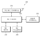
- FIG. 3 is a diagram illustrating an example of a terminal electronic device according to an embodiment of the present disclosure.
- the terminal electronic device 200 of the present invention may include a second memory 230, a second processor 240, a second input / output interface 250, a second display 260, and a second communication interface ( 270).
- the second memory 230 may store a program or data related to performing a function of the terminal electronic device 200.
- the second memory 230 may store a kernel, middleware, an API, an application program, and the like.
- the second memory 230 may store connection information with the image acquisition apparatus 100 and image list information stored in the image acquisition apparatus 100.
- the second memory 230 may include at least one file corresponding to the first camera image and the second camera image provided by the image capturing apparatus 100, and at least one closed image image provided by the image capturing apparatus 100 ( For example, spherical content obtained by stitching the first camera image and the second camera image of the image capturing apparatus 100 may be stored.
- the second memory 230 may store old content received from a designated server.
- the second processor 240 may provide an editing function relating to at least some area of the spherical content.
- the second processor 240 may output the spherical content to the second display 260 in response to a user input.
- the second processor 240 may output at least one patch image (eg, a specific image that may be disposed in at least some area of the spherical content) in response to a user input.
- the second processor 240 outputs a patch list including at least one patch, converts a designated image into a patch image (eg, a 2D circular image or a 3D image), and a patch image from a designated server.
- At least one function of receiving a function may be provided.
- the second processor 240 converts the closed image into a virtual VR image in relation to the image output through the HMD device.
- the converted virtual VR image may be output.
- the virtual VR image may include an image in which at least a portion of the closed image is arranged into display regions divided into a left eye region and a right eye region so that the closed image may be viewed through a head mounted device.
- the second input / output interface 250 may serve as, for example, an interface capable of transferring a command input from a user or data input from another external device to other component (s) of the terminal electronic device 200. have.
- the second input / output interface 250 may output a command or data received from other component (s) of the terminal electronic device 200 to a user or another external device.
- the second input / output interface 250 may generate an input signal related to the control of the image capturing apparatus 100 in response to a user input.
- the input / output interface 250 may include an input signal requesting a search of the image acquisition apparatus 100 or a connection with a designated image acquisition apparatus 100, an input signal related to photographing control of the image acquisition apparatus 100, and an image acquisition apparatus.
- An input signal for requesting an image transmission of the image 100 and an input signal for capturing a specific image may be generated in response to a user input while reproducing content provided by the image obtaining apparatus 100.
- the input / output interface 150 may include an audio device.
- the audio device outputs at least one piece of audio information related to the control of the image capturing apparatus 100 (eg, pre-stored guide information or an effect sound in relation to photographing state information or image transmission state information of the image capturing apparatus 100). can do.
- the audio device may collect a voice signal related to the capture control or the image transmission control of the image acquisition device 100 and transmit the voice command extracted by voice recognition to the second processor 240. Based on this, the audio device may support input of shooting control or image transmission control of the image capturing apparatus 100 by voice.
- the second display 260 may be, for example, a liquid crystal display (LCD), a light-emitting diode (LED) display, an organic light emitting diode (OLED) display, or a micro Microelectromechanical systems (MEMS) displays, or electronic paper displays.
- the second display 260 may display, for example, various types of content (eg, text, images, videos, icons, symbols, etc.).
- the second display 260 may include a touch screen, and for example, may receive a touch, gesture, proximity, or hovering input using an electronic pen or a part of a user's body.
- the second display 260 may output various screens related to editing old content.
- the second display 260 may display a screen including a circular image having a predetermined size in the center and a background (eg, a solid background) disposed at the periphery of the circular image in relation to the spherical content.
- the spherical content may be displayed in various screen states according to the displayed time point.
- the second display 260 has a center point of the spherical content as a starting point for viewing (eg, viewing or observing or viewing the content), but the starting point of the viewing is located at the bottom center of the spherical content, so that it is far from the starting point of viewing. You can output a mirror ball viewing image that shows rounded areas.
- the second display 260 may output a top view image in which the center point of the spherical content is displayed at the center of the screen (for example, the center of the circular image).
- the second communication interface 270 may establish communication between the terminal electronic device 200 and an external device (eg, the image acquisition device 100).
- the second communication interface 270 may be connected to a network through wireless or wired communication to communicate with an external device.
- Wireless communication is, for example, a cellular communication protocol, and includes Long-Term Evolution (LTE), LTE-Advanced (LTE-A), Code Division Multiple Access (CDMA), Wideband CDMA (WCDMA), and Universal Mobile Telecommunications System (UMTS).
- LTE Long-Term Evolution
- LTE-A LTE-Advanced
- CDMA Code Division Multiple Access
- WCDMA Wideband CDMA
- UMTS Universal Mobile Telecommunications System
- WiBro Wireless Broadband
- GSM Global System for Mobile Communications
- the second communication interface 270 may include a short range communication module (eg, BT, WIFI communication hardware interface) capable of communicating with the wearable electronic device 200 or the image acquisition device 100.
- the second communication interface 270 may include at least one communication module capable of performing Near Field Communication (NFC), magnetic stripe transmission (MST), scanner communication, or the like.
- the second communication interface 270 may receive spherical content from the image obtaining apparatus 100.
- the second communication interface 270 performs a peripheral scan using a designated communication module (eg, a short-range communication module, BT, WiFi, Soft AP, etc.) corresponding to a user input, and scans the scan information.
- a communication channel may be formed with the image acquisition apparatus 100 based on the result.
- the second communication interface 270 may receive old content from a server in response to a user input.
- FIG. 4 is a diagram illustrating an example of an old content editing method according to an embodiment of the present invention.
- the second processor 240 in relation to an old content editing method, in operation 401, the second processor 240 generates a specified event (eg, user input, receiving old content from the image obtaining apparatus 100, and providing old content).
- the old content may be output to the second display 260 in response to the designated server connection and the old content received from the server.
- the spherical content display screen may include, for example, a circular image displayed at a predetermined size in the center of the screen and a background surrounding the circular image.
- the circular image may include an image displayed corresponding to a predetermined time point of the spherical content.
- the circular image may include at least one of a mirror ball viewing image and a top view image.
- the second processor 240 may determine whether an input event relating to execution of a patch function corresponding to editing of at least some areas of the spherical content occurs. In this regard, the second processor 240 may output a menu item or an icon related to the old content editing. If the generated event is not an input event related to the execution of the patch function, in operation 405, the second processor 240 may perform a designated function according to the event type. For example, the second processor 240 may perform an email function, a call function, a chat function, etc. according to the event type.
- the second processor 240 may detect the center point of the spherical content and display the top view image. For example, the second processor 240 may detect, as a center point of the spherical content, a starting point (eg, a location where a camera is disposed) at which the image is captured at the time of generating the spherical content. In this regard, the second processor 240 may search for a portion of the spherical content stitched with the image and determine the stitched portion in the designated direction among the stitched portions as the center point of the image.
- a starting point eg, a location where a camera is disposed
- the stitching part is an area where the images are stitched together, and the second processor 240 recognizes a certain part as the stitching part within the bounded range between the images through the image filtering, and the end point of the direction toward the center of the stitching part is spherical content. Can be judged as the center point.
- the second processor 240 arranges the center point in the center of the screen, and displays the top view image in a direction of looking at the center point at a certain point of the outside (for example, the outer portion of the spherical content). It can be displayed in the form of a circular image.
- the second processor 240 may display a circular image looking at the center point at the outer end of the vertical direction upward from the center point of the spherical content. According to an embodiment of the present disclosure, the second processor 240 may output at least one patch item related to applying the patch function while displaying the spherical content in the top view image display method.
- the second processor 240 may check whether an event relating to patch item selection occurs. If a specified time elapses without an event related to patch item selection, the second processor 240 may skip operation 411 or operation 413. Alternatively, the second processor 240 may maintain a screen output for selecting at least one patch item.
- the second processor 240 may apply a patch image corresponding to the selected patch item to the center point of the spherical content.
- a patch image of a predetermined size having a predetermined color or pattern or a designated 2-dimension or 3-dimension shape may be disposed at the center point of the spherical content.
- the patch image may be disposed to cover a structure (eg, a tripod or a hand) that is crushed, at least partially cut off, or at least partially overlapped at the center point of the spherical content.
- the second processor 240 may display a circular image in a mirror ball viewing image manner. Accordingly, the patch image may be disposed and displayed at the bottom center of the circular image.
- the second processor 240 may check whether there is an event related to ending display of the old content. If there is no event related to the end of the display of the old content, the process may be branched to operation 401 to perform the following operation again or the operation may be branched to operation 407 to output the patch item selection screen.
- FIG. 5 is a view showing an example of a method related to the operation of a patch function according to an embodiment of the present invention.
- the second processor 240 provides at least one of a patch list function, a conversion item provision, and a patch download function described below by default, or any one function. It may be set to provide an icon or a menu for selecting.
- the second processor 240 may determine whether an event relating to a request relating to output of a patch list occurs.
- the second processor 240 may be configured to output a patch list to the display by default (or automatically, or basically) in connection with executing the patch function.
- the second processor 240 may be set to provide an icon or a menu related to outputting a patch list on a screen on which old content is displayed. If the generated event is a request (eg, a user input or a patch function execution request) related to outputting the patch list, in operation 503, the second processor 240 may display the stored patch list.
- the second processor 240 may be configured to search or select at least one patch item from a patch list.
- the second processor 240 may select a patch item in response to the corresponding event.
- the second processor 240 may apply a patch image corresponding to the selected patch item (eg, arrange the patch image in a predetermined size on a portion of the sphere content (eg, a center point of the sphere content)).
- the second processor 240 may be set to display edit items for adjusting at least one of the size, color, and shape of the displayed patch image.
- the second processor 240 may determine whether the event is related to importing a patch.
- the second processor 240 may be set to output a designated menu or icon to the second display 260 in relation to a patch import function.
- the second processor 240 may apply a patch import function by default when an event for requesting the execution of the old content editing function occurs.
- the second processor 240 may be configured to output a designated image folder, for example, a gallery execution screen, to the second display 260.
- the second processor 240 may be set to output an execution screen of an image download folder as a designated image folder.
- the second processor 240 may receive an event related to image selection.
- the second processor 240 may convert the selected image into a spherical patch.
- the second processor 240 may output a translation interface associated with the old patch transition.
- the second processor 240 may automatically convert the selected image into a 2D or 3D sphere.
- the second processor 240 may adjust the size, shape, color, etc. of the converted image according to a user input.
- the second processor 240 may support setting an initial display direction (or display surface).
- the second processor 240 may be configured to display the converted spherical patch by applying it to the center point of the spherical content.
- the second processor 240 may extract a circular image having a size specified based on a center point or at least one object of the selected image.
- the second processor 240 automatically selects a specified object (eg, an object placed at a specified position or an object of a specified size or shape, etc.) in the selected image or at least in response to user input.
- a spherical patch transformation may be performed by selecting one object and performing 3D modeling of the selected object based on a specified algorithm.
- the specified algorithm may include, for example, instructions for selecting a pre-stored 3D texture corresponding to the selected object and performing 3D modeling based on the selected 3D texture.
- the specified algorithm may copy a plurality of selected objects, list the plurality of copied objects at regular intervals, and then attach the objects to perform 3D modeling.
- the second processor 240 may check whether the event relates to “downloading patch”. In relation to the patch download function, the second processor 240 may be set to output a menu item or an icon for selecting the patch download function to the second display 260. Alternatively, when the old content editing function is executed, the second processor 240 may execute a patch download function by default (or automatically or basically). When the patch download function is executed, as in operation 523, the second processor 240 may perform a designated server connection. Alternatively, the second processor 240 may output an input window related to the server address input.
- the second processor 240 may receive a server page for downloading at least one patch item from the server, and output the second page 260 to the second display 260 in operation 525.
- the second processor 240 may receive a patch image corresponding to the selected patch item from the server.
- the second processor 240 may store the patch provided by the server in the designated second memory 230 area and apply the patch to the center point of the spherical content.
- the method for editing a spherical content may include displaying spherical content having at least a part of a spherical shape based on a center point, detecting a center point of the spherical content, and a user input.
- the method may include outputting a patch image designated at a center point of the spherical content.
- the method may further include outputting a patch list including patch items corresponding to at least one patch image.
- the method may further include converting an image selected corresponding to a user input into a circular or spherical shape that may be disposed at a center point of the spherical content, and providing the patch image as the patch image.
- the method may further include accessing a server providing a patch image in response to a user input, receiving a user input of selecting a patch item included in the server page, and patch corresponding to the patch item.
- the method may further include receiving an image and disposing the received patch image at the center point.
- the method may further include displaying the received patch item in a patch list.
- the outputting operation may include detecting a center point of the spherical content, adjusting an arrangement of the spherical content so that the center point is disposed at the center of the screen, and an image of the structure disposed at the center point of the spherical content. Automatically adjusting and outputting a size of the patch image corresponding to a size of the patch image; outputting a guide for adjusting at least one of the size and color of the patch image; The method may further include at least one of extracting a color and applying a color similar to the extracted color or the extracted color to the patch image color.
- the method may further include any one of an operation of outputting a view screen in which at least a portion of the patch image is disposed at the center of the lower center of the screen as the patch image is applied.
- the method may further include displaying a recommended patch item corresponding to a patch image of a specified type based on at least one of tag information of the spherical content and a type of at least one object included in the spherical content. It may further include.
- FIG. 6 is a diagram illustrating an example of an old content editing screen interface according to an embodiment of the present invention.
- the terminal electronic device 200 displays a spherical content including a mirror ball viewing image 610 and a background 620 in the form of a circular image as shown on a screen 601. It may output to the display 260.
- the mirror ball viewing image 610 may be an image in which a photographing start point of the camera is disposed at the bottom of the center of the screen, and the display area is rounded away from the photographing start point.
- the background 620 may be disposed to surround the mirror ball viewing image 610 and may be displayed in a designated color (eg, white or black). Alternatively, the background 620 may have a different color from the primary colors of the mirror ball viewing image 610 in order to easily recognize the mirror ball viewing image 610. For example, the background 620 may have a complementary color that highlights the primary color applied to the mirror ball viewing image 610.
- the second processor 240 may extract a main color of the mirror ball viewing image 610 and apply a color of the extracted main color and the complementary color relationship to the background 620.
- the second processor 240 of the terminal electronic device 200 may provide a similar color by reprocessing the extracted color to reduce the color difference between the mirror ball viewing image 610 and the surrounding color. For example, the second processor 240 may provide a color similar to at least one of the colors extracted from the color coordinate system and adjacent colors (eg, green, green, and green similar to green when the extracted color is green). can do.
- edit items 620a related to spherical content editing may be disposed at one side of the background 620.
- the edit items 620a may be, for example, rotation related items 621, tone adjustment items 622, effect period items 623, patch function items Pathc ( 624, and decoration items 625, and the like.
- the second display 260 may output the patch application screen as in the screen 603.
- the patch application screen may include a top view image 630 and a background 620.
- the top view image 630 may include an image to which a center point of the spherical content (for example, a camera photographing start point) is disposed at the center of the screen, and a direction to which the center point is viewed from the outside of the spherical content is applied.
- the top view image 630 may include a structure image 631 disposed at a predetermined position (eg, a center point).
- the structure image 631 may correspond to at least a part of the structure around the camera applied when generating spherical content, such as a tripod supporting the camera or a user's hand.
- the patch list 630a may be displayed on one side of the background 620.
- the patch list 630a may include at least one 2D image or 3D image that may replace the structure image 631.
- the patch image 632 may be disposed to cover the structure image 631, as shown in a screen 605.
- the patch image 632 may have, for example, a specified size and shape and a specified color.
- the second processor 240 may output a color change table 630b that can change the color of the patch image 632 to one side of the second display 260.
- the second processor 240 may output an adjustment guide 633 for adjusting the size and direction of the patch image 632 to an area adjacent to the patch image 632. When a touch event related to the adjustment guide 633 occurs, the second processor 240 may adjust and display the size and direction of the adjustment guide 633 and the patch image 632.
- the second processor 240 may correspond to the top view image 630 or the background 620, or the touch view generated on the boundary area between the top view image 630 and the background 620. ) Can be changed. For example, when a first touch input (eg, pinch zoom-in input) occurs, the second processor 240 may output an enlarged image of the top view image 630. In this operation, the second processor 240 may maintain the overall size of the top view image 630 and display the center point portion at a larger scale. Accordingly, the terminal electronic device 200 may provide an effect of approaching and viewing the center point portion of the top view image 630 closer.
- a first touch input eg, pinch zoom-in input
- the second processor 240 may output a reduced image of the top view image 630.
- the second processor 240 maintains the overall size of the top view image 630 and displays the center point portion or a portion of a certain size including the center point (eg, an adjacent portion within a certain distance relative to the center point) from the previous state. can do. Accordingly, the terminal electronic device 200 may provide an effect of viewing the center point portion of the top view image 630 relatively far.
- the third touch input 651 for example, an input of touching a certain area of the background 620
- the second processor 240 returns to a previous screen state (for example, a 603 screen or a 601 screen). Can be.
- the second processor 240 determines the size of the structure image 631 disposed at the center point, and automatically generates a patch image 632 having a size that can cover all the sizes of the structure image 631. It can be generated and applied to the 605 screen.
- the terminal electronic device 200 may output a control object capable of manipulating the patch image in the patch image.
- the patch image manipulation control object may be provided in various forms according to the type of the spherical content, for example.
- the control object may include a function of manipulating rotation of the patch image, resizing the patch image, and the like in spherical content.
- the control object may include a function for changing a patch image view (eg, a mirror ball viewing image or a top view image).
- the control object may provide a function such as writing text or drawing an image in the patch image.
- FIG. 7 is a diagram illustrating an example of a screen interface associated with applying a patch according to an embodiment of the present invention.
- the second processor 240 may use the top view image 630.
- the first patch image 632 corresponding to the selected patch item 630_1 at a predetermined point (for example, the center point of the spherical content) is output to the second display 260.
- a background 620 may be disposed around the top view image 630, and a patch list 630a may be output to a predetermined region of the background 620.
- the second processor 240 may output a color change table 630b for changing the color of the selected patch item 630_1.
- the second processor 240 may automatically output a color of a predetermined region adjacent to the center point where the first patch image 632 is disposed or in response to a user input.
- the second processor 240 may output the eyedropper icon or the eyedropper menu related to automatic color application to a predetermined area of the second display 260.
- the second processor 240 moves the eyedropper object 710 into a certain area (eg, the first patch image 632) of the top view image 630. Area adjacent to the disposed area).
- the eyedropper object 710 may be changed in position in response to a user input.
- the second processor 240 may extract the color of the spot where the eyedropper object 710 is disposed.
- the color may be applied to the patch image to display the second patch image 634 as shown in the screen 703.
- the second processor 240 may display the third patch image 635 to which the color corresponding to the predetermined position 730 indicated by the touch input or the position where the eyedropper object 710 is disposed is displayed, as shown on a screen 705. Accordingly, the color of the third patch image 635 may be changed to a color similar to the color of the peripheral area. According to various embodiments of the present disclosure, the second processor 240 may display the indicator 630c related to the color of the position where the eyedropper object 710 is disposed in a predetermined region of the color change table 630b.
- FIG. 8 is a diagram illustrating an example of a patch image application screen according to an embodiment of the present invention.
- the display 260 of the terminal electronic device 200 of the present invention may output a circular image on which the patch image is applied to the center point of the spherical content to the second display 260.
- the second processor 240 may display the first mirror ball viewing image 811 along with the background 620 of the second display 260 with the first patch image 810 applied to the center point of the spherical content.
- the first patch image 810 may be disposed at a predetermined size in the center of the lower and lower centers of the circular image.
- the first patch image 810 may be displayed in a disc shape having an asymmetric relationship between the upper and lower portions as shown in the angular direction in which the camera photographs the shape disposed at the center point of the spherical content.
- the patch image may include text.
- the spherical content to which the second patch image 820 including the text is applied may be displayed as shown on the screen 803. Looking at the screen 803, the second mirror ball viewing image 812 may be displayed together with the background 620 while the second patch image 820 is disposed at the center of the middle of the screen. Since the second patch image 820 includes text, the text may be bent at the center of the bottom of the screen.
- FIG. 9 is a diagram illustrating an example of a screen interface related to importing a patch according to an exemplary embodiment.
- the second display 260 may output a background 620 and a top view image 630 as shown in a screen 901.
- the structure image 631 may be disposed at the center point of the top view image 630.
- the second display 260 may output the patch list 910 according to the application of the patch function.
- the patch list 910 may include a patch item 910 generated by image conversion.
- the terminal electronic device 200 may provide a screen interface related to image conversion.
- the second display 260 displays the structure image 631 disposed to cover the patch image 931 corresponding to the selected patch item 910. I can display it.
- the second display 260 may further output a guide for adjusting the size and direction of the patch image 931. According to a user input requesting guide adjustment, the size and arrangement direction of the patch image 931 (eg, an image of a horse) may be changed.
- a deformed patch image 932 (e.g., a portion of the patch image 931 (e.g., a horse's head)) may output a mirror ball viewing image 610 of a shape centered at the center bottom of the circular image.
- the second display 260 may modify the patch.
- Other portions of the image 932 eg, the side of a horse or the tail of a horse, etc. may be displayed in a form disposed at the center bottom center of the mirror ball viewing image 610.
- the terminal electronic device 200 may automatically recommend a patch item based on tag information of an old content or an object analysis included in the old content.
- the terminal electronic device 200 may be a patch item corresponding to a marine animal (eg, a turtle, a whale, etc.) or a patch corresponding to a marine facility (eg, a ship, a lighthouse, etc.) when the old content is content photographed at a seaside.
- the item may be included in the patch list 910 to be displayed.
- the terminal electronic device 200 may output the patch item corresponding to the horse image in the patch list 910.
- the terminal electronic device 200 may include a patch item corresponding to an image of a camel in the patch list 910 and output the patch item.
- the terminal electronic device 200 may display information related to an image currently being displayed on the second display 260.
- the terminal electronic device 200 may display tag information (eg, location of generating old content, time, weather, text information written in relation to the old content), etc. of the old content at a designated location of the second display 260. It can be output with old content or through a separate popup window or a separate page.
- the terminal electronic device 200 may describe description information related to the old content currently being displayed (for example, old content title information, old content generation terminal information, old content creator information, and types of objects included in the old content). Etc.) can be output.
- the terminal electronic device 200 of the present invention removes the structure image 631 that is out of harmony with the surroundings in the center of the spherical contents, and arranges a patch image that can be animated with the surroundings, thereby completing the completeness of the spherical contents. To provide a more natural content viewing.
- FIG. 10 is a diagram illustrating an example of a screen interface related to patch item download according to an embodiment of the present invention.
- the second display 260 may display a background 620 and a circular image (eg, the top view image 630) as in the screen 1001. You can output In addition, the second display 260 may output the patch list 630a.
- the structure image 631 may be disposed at the center point of the top view image 630.
- the second display 260 may change the patch list 630a items in response to the touch input as in the screen 1003. In response, the patch list 630a may display the patch download item 1030.
- the terminal electronic device 200 may access a specified server and output a server page for selecting a patch item provided by the server, as shown in a screen 1005.
- the server page may include, for example, items related to a plurality of patch images.
- the terminal electronic device 200 provides an input event corresponding to the selection of the first item 1051 to the server page, and from the server page, the first item 1051.
- the terminal electronic device 200 may store a patch image corresponding to the first item 1051 in a memory.
- the display 260 of the terminal electronic device 200 may display the first patch image 1031 corresponding to the first patch item 1051 as shown in the screen 1007.
- the output may be performed at a predetermined point (eg, a center point at which the structure image 631 is disposed) of the 630.
- the patch list 630a may be displayed including the first patch item 1070.
- an electronic device may include a memory for storing spherical content having at least a part of a spherical shape based on a center point, a display for outputting the spherical content, the memory, and the display and the electronic device. And a processor connected to the processor, wherein the processor is configured to place a designated patch image at a center point of the spherical content in response to a user input.
- the processor may be configured to output a patch list including patch items corresponding to at least one patch image.
- the processor may be configured to convert a selected image in response to a user input into a circular or spherical shape that may be disposed at a center point of the spherical content.
- the processor may be configured to access a server providing a patch image in response to a user input and output a server page provided by the server.
- the processor is configured to receive a patch image corresponding to the patch item and to place the received patch image at the center point in response to a user input of selecting a patch item included in the server page. Can be.
- the processor may be configured to display the received patch item in a patch list.
- the processor may be configured to detect a center point of the spherical content and adjust a display state of the spherical content so that the center point may be disposed at the center of the screen.
- the processor may be configured to output a viewing image in which at least a portion of the patch image is disposed at the center of the lower center of the screen according to the application of the patch image.
- the processor may be configured to automatically adjust and output the size of the patch image corresponding to the size of the structure image disposed at the center point of the spherical content.
- the processor may be configured to output a guide for adjusting at least one of a size and a color of the patch image.
- the processor may be configured to extract a color of an area adjacent to a center point at which the patch image is output and change the extracted color to be the same as or similar to the patch image color.
- the processor is configured to display a recommended patch item corresponding to a patch image of a specified type based on at least one of tag information of the old content and a type of at least one object included in the old content. Can be.
- FIG. 11 is a diagram illustrating another example of an old content operation system according to another embodiment of the present invention.
- an older content management system includes an image acquisition device 100, a terminal electronic device 200, and a head mount device 400 capable of mounting the terminal electronic device 200. can do.
- the old content management system may further include a remote controller 500 (remote control).
- the image acquisition device 100 includes a plurality of cameras 110 and 120, and acquires an image in response to at least one of a control signal or a remote controller 500 of the terminal electronic device 200 connected to a user input or communication. can do.
- the image acquisition device 100 may store the acquired image or transmit the image to the terminal electronic device 200.
- the image acquisition apparatus 100 may be the same or similar to the image acquisition apparatus described with reference to FIGS. 1 and 2. Additionally or alternatively, the image acquisition device 100 may include a wing 102.
- the wing unit 102 may generate a lift force that may cause the image acquisition apparatus 100 to rise above a predetermined distance from the ground by using power. Accordingly, the image acquisition apparatus 100 may collect the spherical content in response to a control signal of the terminal electronic device 200 or the remote controller 500 in a state of floating from the ground to a specified height.
- the terminal electronic device 200 may establish a communication channel with the image acquisition device 100 and receive an image from the image acquisition device 100.
- the terminal electronic device 200 may use the virtual VR content (or the virtual VR image) based on an image provided by the image capturing apparatus 100 (eg, images obtained by the first camera 110 and the second camera 120). ) Can be printed.
- the virtual VR content may be output based on, for example, a closed image obtained by stitching edges of the first camera image and the second camera image.
- the virtual VR content may include an image provided to divide at least a portion of the closed image currently displayed into a left eye area and a right eye area, respectively.
- the terminal electronic device 200 may output virtual VR content to the terminal display.
- the terminal electronic device 200 may provide a patch function capable of applying the aforementioned patch image.
- the terminal electronic device 200 may split the screen and output a part of the same virtual VR content to each of the divided areas (eg, the left eye area and the right eye area).
- the terminal electronic device 200 may maintain a distance between the left eye area and the right eye area by a predetermined width, and may output a specified image in the corresponding width, or may output a partial right edge image of the left eye area and a partial left edge image of the right eye area. have.
- the terminal electronic device 200 may output a partial region of the closed image as virtual VR content.
- a user input for example, the terminal electronic device 200 detects the sensor of the rotating-terminal electronic device 200 or the sensor included in the head-mounted device according to the head rotation or the body rotation
- the terminal electronic device 200 may select at least one patch item corresponding to an input direction (eg, up, down, left, right, diagonal directions, etc.) and apply a patch image corresponding to the selected patch item to a center point of the spherical content.
- the terminal electronic device 200 when mounted on the head mounted device 400, may convert the closed image stored in the memory into virtual VR content according to a setting or a user input and output the virtual VR content. Alternatively, the terminal electronic device 200 may automatically output the virtual VR content when the terminal electronic device 200 is mounted on the head mounted device 400 in a state in which the virtual VR content is prepared. According to various embodiments of the present disclosure, the terminal electronic device 200 may convert and output real-time virtual VR content based on the images (eg, the first camera image and the second camera image) transmitted by the image capturing apparatus 100. . The terminal electronic device 200 may be mounted on the head mount device 400 and physically coupled to recognize the insertion of the head mount device 400.
- the head mounted device 400 may include a device on which the terminal electronic device 200 is mounted and which may view a screen output on the second display 260 of the terminal electronic device 200 with a left eye and a right eye, respectively. have.
- the head mount device 400 may include a structure such as a belt that can be worn on a user's head, and may include an area in which the terminal electronic device 200 may be mounted.
- the head mounted device 400 may further include a button or a touch pad that is functionally connected to the terminal electronic device 200 to be mounted to generate an input signal related to the control of the terminal electronic device 200. .
- the remote controller 500 may be communicatively connected to the image acquisition device 100 based on a short range communication module (eg, a Bluetooth communication module), and may transmit a signal related to the control of the image acquisition device 100 in response to a user input. .
- the remote controller 500 may generate and transmit a signal of a designated frequency band (for example, a frequency band that the image acquisition apparatus 100 may receive).
- the remote controller 500 may include at least one physical button or a touch pad and transmit a signal corresponding to a user input to the image acquisition apparatus 100. Accordingly, the user may control image acquisition and transmission of the image capturing apparatus 100 under the control of the remote controller 500 while the terminal electronic apparatus 200 is mounted with the head mounted apparatus 400 mounted thereon. .
- the terminal electronic device 200 stores an image (eg, outdated content) transmitted by the image acquisition device 100, and stores the stored image in the head mounted device. It converts the virtual VR content that can be executed at 400 and outputs it to the terminal electronic device 200.
- the spherical content operation system may convert the structure image disposed at the center point of the acquired spherical content into a patch image while checking the spherical content of the terminal electronic device 200 using the head mounted device 400.
- FIG. 12 is a diagram illustrating an example of a network environment associated with operation of a terminal electronic device according to an embodiment of the present disclosure.
- the terminal electronic device 1201 may connect the bus 1210, the processor 1220, the memory 1230, the input / output interface 1250, the display 1260, and the communication interface 1270. It may include. According to an embodiment of the present disclosure, the terminal electronic device 1201 may omit at least one of the components or additionally include other components.
- the bus 1210 may include circuitry that connects the components 1220-1270 to each other and transfers communication (eg, control messages or data) between the components.
- the processor 1220 eg, the processor of the electronic device 10) may include one or more of a central processing unit, an application processor, and a communication processor (CP).
- the processor 1220 may execute, for example, an operation or data processing related to control and / or communication of at least one other component of the terminal electronic device 1201.
- the memory 1230 may include volatile and / or nonvolatile memory.
- the memory 1230 may store, for example, commands or data related to at least one other element of the terminal electronic device 1201.
- the memory 1230 may store software and / or a program 1240.
- the program 1240 may include, for example, a kernel 1241, middleware 1243, an application programming interface (API) 1245, an application program (or “application”) 1247, or the like.
- API application programming interface
- At least a portion of kernel 1241, middleware 1243, or API 1245 may be referred to as an operating system.
- Kernel 1241 may be, for example, system resources (e.g., used to execute an action or function implemented in other programs (e.g., middleware 1243, API 1245, or application program 1247).
- the bus 1210, the processor 1220, or the memory 1230 may be controlled or managed.
- the kernel 1241 provides an interface for controlling or managing system resources by accessing individual components of the terminal electronic device 1201 from the middleware 1243, the API 1245, or the application program 1247. can do.
- the middleware 1243 may serve as an intermediary for allowing the API 1245 or the application program 1247 to communicate with the kernel 1241 to exchange data. Also, the middleware 1243 may process one or more work requests received from the application program 1247 according to priority. For example, the middleware 1243 may use system resources (eg, the bus 1210, the processor 1220, or the memory 1230, etc.) of the terminal electronic device 1201 for at least one of the application programs 1247. Prioritize and process the one or more work requests.
- the API 1245 is an interface for the application 1247 to control a function provided by the kernel 1241 or the middleware 1243. For example, the API 1245 may include at least a file control, window control, image processing, or character control.
- the input / output interface 1250 may transfer, for example, a command or data input from a user or another external device to other component (s) of the terminal electronic device 1201 or another configuration of the terminal electronic device 1201. Commands or data received from the element (s) may be output to a user or other external device.
- Display 1260 is, for example, a liquid crystal display (LCD), a light emitting diode (LED) display, an organic light emitting diode (OLED) display, or a microelectromechanical system (MEMS) display, or an electronic paper display. It may include.
- the display 1260 may display, for example, various contents (eg, text, images, videos, icons, and / or symbols, etc.) to the user.
- the display 1260 may include a touch screen, and may receive, for example, a touch, gesture, proximity, or hovering input using an electronic pen or a part of a user's body.
- the communication interface 1270 may be, for example, between the terminal electronic device 1201 and an external device (eg, the first external terminal electronic device 1202, the second external terminal electronic device 1204, or the server 1206). You can set up communication.
- the communication interface 1270 may be connected to the network 1262 through wireless or wired communication to communicate with an external device (eg, the second external terminal electronic device 1204 or the server 1206).
- the wireless communication may be, for example, LTE, LTE Advance (LTE-A), code division multiple access (CDMA), wideband CDMA (WCDMA), universal mobile telecommunications system (UMTS), wireless broadband (WiBro), or global network (GSM).
- LTE Long Term Evolution
- LTE-A LTE Advance
- CDMA code division multiple access
- WCDMA wideband CDMA
- UMTS universal mobile telecommunications system
- WiBro wireless broadband
- GSM global network
- the wireless communication may include, for example, wireless fidelity (WiFi), Bluetooth, Bluetooth low power (BLE), Zigbee, near field communication (NFC), magnetic secure transmission, and radio. It may include at least one of a frequency (RF) or a body area network (BAN).
- GNSS GNSS.
- the GNSS may be, for example, a Global Positioning System (GPS), a Global Navigation Satellite System (Glonass), a Beidou Navigation Satellite System (hereinafter referred to as “Beidou”) or Galileo, the European global satellite-based navigation system.
- GPS Global Positioning System
- Glonass Global Navigation Satellite System
- Beidou Beidou Navigation Satellite System
- Galileo the European global satellite-based navigation system.
- Wired communication may include, for example, at least one of a universal serial bus (USB), a high definition multimedia interface (HDMI), a standard standard232 (RS-232), a power line communication, a plain old telephone service (POTS), and the like. have.
- the network 1262 may include at least one of a telecommunications network, eg, a computer network (eg, LAN or WAN), the Internet, or a telephone network.
- a telecommunications network eg, a computer network (eg, LAN or WAN), the Internet, or a telephone network.
- the terminal electronic device 1201 may communicate with the first terminal electronic device 1202 based on the short range communication 1264.
- Each of the first and second external terminal electronic devices 1202 and 1204 may be the same or different type of device as the terminal electronic device 1201. According to various embodiments of the present disclosure, all or part of operations executed in the terminal electronic device 1201 may be executed in another or a plurality of electronic devices (for example, terminal electronic devices 1202 and 1204 or the server 1206). According to an embodiment of the present disclosure, when the terminal electronic device 1201 needs to perform a function or service automatically or by request, the terminal electronic device 1201 may instead execute or additionally execute the function or service by itself.
- At least some functions associated therewith may be requested to another device (eg, terminal electronic device 1202, 1204, or server 1206)
- Other electronic device eg, terminal electronic device 1202, 1204, or server 1206
- the terminal electronic device 1201 may process the received result as it is or additionally to request the requested function.
- There can provide services to them for example, cloud computing, distributed computing or client-server computing techniques can be used.
- module may refer to a unit that includes one or a combination of two or more of hardware, software, or firmware.
- a “module” may be interchangeably used with terms such as, for example, unit, logic, logical block, component, or circuit.
- the module may be a minimum unit or part of an integrally constructed part.
- the module may be a minimum unit or part of performing one or more functions.
- the “module” can be implemented mechanically or electronically.
- a “module” is one of application-specific integrated circuit (ASIC) chips, field-programmable gate arrays (FPGAs), or programmable-logic devices that perform certain operations, known or developed in the future. It may include at least one.
- ASIC application-specific integrated circuit
- FPGAs field-programmable gate arrays
- an apparatus eg, modules or functions thereof
- a method eg, operations
- computer-readable storage media in the form of a program module. It can be implemented as a command stored in.
- the instruction is executed by a processor (eg, the processor 120)
- the one or more processors may perform a function corresponding to the instruction.
- the computer-readable storage medium may be the memory 130, for example.
- Computer-readable recording media include hard disks, floppy disks, magnetic media (e.g. magnetic tapes), optical media (e.g. CD-ROMs, digital versatile discs), magnetic- Optical media (eg floptical disks), hardware devices (eg ROM, RAM, flash memory, etc.), etc.
- program instructions may be created by a compiler. It may include not only machine code, such as losing, but also high-level language code executable by a computer using an interpreter, etc.
- the hardware device described above may be configured to operate as one or more software modules to perform the operations of various embodiments. And vice versa.
- Modules or program modules according to various embodiments of the present disclosure may include at least one or more of the above components, some of them may be omitted, or may further include other additional components.
- Operations performed by a module, program module, or other component according to various embodiments of the present disclosure may be executed in a sequential, parallel, repetitive, or heuristic manner. In addition, some operations may be executed in a different order, may be omitted, or other operations may be added.
Abstract
본 발명의 실시 예는 중심점을 기준으로 적어도 일부가 구의 일부 형상으로 마련된 구형 컨텐츠를 저장하는 메모리, 상기 구형 컨텐츠를 출력하는 디스플레이, 상기 메모리 및 상기 디스플레이와 전기적으로 연결되는 프로세서를 포함하고, 상기 프로세서는 사용자 입력에 대응하여, 상기 구형 컨텐츠의 중심점에 지정된 패치 이미지를 배치하도록 설정된 전자 장치를 개시한다. 이 외에도 명세서를 통해 파악되는 다양한 실시 예가 가능하다.
Description
다양한 실시 예는 이미지 편집에 관한 것이다.
최근 VR(Virtual Reality) 장치의 등장으로, VR 또는 AR(Augmented Reality) 등에 사용할 수 있는 구형 컨텐츠에 대한 관심이 커지고 있다. 구형 컨텐츠는 뷰잉(Viewing) 지점을 기준으로 전방위(360 degree)에 대한 확인이 가능한 컨텐츠를 포함할 수 있다. 구형 컨텐츠는, 예컨대, 앞뒤로 배치되고 지정된 각도 이상 촬영 가능한 카메라를 이용하여 생성될 수 있다.
상기 카메라를 이용하여 구형 컨텐츠를 생성할 경우, 카메라의 하단 (또는 하부)에 배치된 구조물이나 기구물 또는 수단(예: 삼각대, 손 등) 등도 촬영될 수 있다. 이 과정에서, 구형 컨텐츠 중 카메라 하부 구조물이 배치된 지점에서의 구조물 이미지는 찌그러지거나 일부가 잘려 보이는 등 어색하게 표현되는 문제가 있었다.
본 발명의 다양한 실시예들은 보다 용이하고 직관적인 컨텐츠 편집이 가능한 구형 컨텐츠 편집 방법 및 이를 지원하는 전자 장치를 제공한다.
본 발명의 다양한 실시 예에 따른 전자 장치는 중심점을 기준으로 적어도 일부가 구의 일부 형상으로 마련된 구형 컨텐츠를 저장하는 메모리, 상기 구형 컨텐츠를 출력하는 디스플레이, 상기 메모리 및 상기 디스플레이와 전기적으로 연결되는 프로세서를 포함하고, 상기 프로세서는 상기 구형 컨텐츠의 중심점에 지정된 패치 이미지를 배치하도록 설정될 수 있다.
다양한 실시 예에 따르면, 구형 컨텐츠 편집 방법은 중심점을 기준으로 적어도 일부가 구의 일부 형상으로 마련된 구형 컨텐츠를 표시하는 동작, 상기 구형 컨텐츠의 중심점을 검출하는 동작, 상기 구형 컨텐츠의 중심점에 지정된 패치 이미지를 출력하는 동작을 포함할 수 있다.
상술한 다양한 실시 예들은 구형 컨텐츠의 적어도 일부 영역의 편집을 보다 용이하고 직관적이며, 사용자 기호에 맞는 방식으로 수행할 수 있도록 지원한다.
도 1은 본 발명의 실시 예에 따른 구형 컨텐츠 운용 시스템의 한 예를 나타낸 도면이다.
도 2는 본 발명의 실시 예에 따른 이미지 획득 장치의 한 예를 나타낸 도면이다.
도 3은 본 발명의 실시 예에 따른 단말 전자 장치의 한 예를 나타낸 도면이다.
도 4는 본 발명의 실시 예에 따른 구형 컨텐츠 편집 방법의 한 예를 나타낸 도면이다.
도 5는 본 발명의 실시 예에 따른 패치 기능 운용과 관련한 방법의 한 예를 나타낸 도면이다.
도 6은 본 발명의 실시 예에 따른 구형 컨텐츠 편집 화면 인터페이스의 한 예를 나타낸 도면이다.
도 7은 본 발명의 실시 예에 따른 패치 적용과 관련한 화면 인터페이스의 한 예를 나타낸 도면이다.
도 8은 본 발명의 실시 예에 따른 패치 이미지 적용 화면의 한 예를 나타낸 도면이다.
도 9는 본 발명의 한 실시 예에 따른 패치 가져오기와 관련한 화면 인터페이스의 한 예를 나타낸 도면이다.
도 10은 본 발명의 한 실시 예에 따른 패치 아이템 다운로드와 관련한 화면 인터페이스의 한 예를 나타낸 도면이다.
도 11은 본 발명의 다른 실시 예에 따른 구형 컨텐츠 운용 시스템의 다른 한 예를 나타낸 도면이다.
도 12는 본 발명의 실시 예에 따른 단말 전자 장치 운용과 관련한 네트워크 환경의 한 예를 나타낸 도면이다.
이하, 본 발명의 다양한 실시 예가 첨부된 도면을 참조하여 기재된다. 그러나, 이는 본 발명을 특정한 실시 형태에 대해 한정하려는 것이 아니며, 본 발명의 실시 예의 다양한 변경(modification), 균등물(equivalent), 및/또는 대체물(alternative)을 포함하는 것으로 이해되어야 한다. 도면의 설명과 관련하여, 유사한 구성요소에 대해서는 유사한 참조 부호가 사용될 수 있다.
본 문서에서, "가진다", "가질 수 있다", "포함한다", 또는 "포함할 수 있다" 등의 표현은 해당 특징(예: 수치, 기능, 동작, 또는 부품 등의 구성요소)의 존재를 가리키며, 추가적인 특징의 존재를 배제하지 않는다.
본 문서에서, "A 또는 B", "A 또는/및 B 중 적어도 하나", 또는 "A 또는/및 B 중 하나 또는 그 이상" 등의 표현은 함께 나열된 항목들의 모든 가능한 조합을 포함할 수 있다. 예를 들면, "A 또는 B", "A 및 B 중 적어도 하나", 또는 "A 또는 B 중 적어도 하나"는, (1) 적어도 하나의 A를 포함, (2) 적어도 하나의 B를 포함, 또는 (3) 적어도 하나의 A 및 적어도 하나의 B 모두를 포함하는 경우를 모두 지칭할 수 있다.
다양한 실시 예에서 사용된 "제1", "제2", "첫째", 또는 "둘째" 등의 표현들은 다양한 구성요소들을, 순서 및/또는 중요도에 상관없이 수식할 수 있고, 해당 구성요소들을 한정하지 않는다. 상기 표현들은 한 구성요소를 다른 구성요소와 구분하기 위해 사용될 수 있다. 예를 들면, 제1 사용자 기기와 제2 사용자 기기는, 순서 또는 중요도와 무관하게, 서로 다른 사용자 기기를 나타낼 수 있다. 예를 들면, 본 발명의 권리 범위를 벗어나지 않으면서 제1 구성요소는 제2 구성요소로 명명될 수 있고, 유사하게 제2 구성요소도 제1 구성요소로 바꾸어 명명될 수 있다.
어떤 구성요소(예: 제1 구성요소)가 다른 구성요소(예: 제2 구성요소)에 "(기능적으로 또는 통신적으로) 연결되어((operatively or communicatively) coupled with/to)" 있다거나 "접속되어(connected to)" 있다고 언급된 때에는, 상기 어떤 구성요소가 상기 다른 구성요소에 직접적으로 연결되거나, 다른 구성요소(예: 제3 구성요소)를 통하여 연결될 수 있다고 이해되어야 할 것이다. 반면에, 어떤 구성요소(예: 제1 구성요소)가 다른 구성요소(예: 제2 구성요소)에 "직접 연결되어" 있다거나 "직접 접속되어" 있다고 언급된 때에는, 상기 어떤 구성요소와 상기 다른 구성요소 사이에 다른 구성요소(예: 제3 구성요소)가 존재하지 않는 것으로 이해될 수 있다.
본 문서에서 사용된 표현 "~하도록 구성된(또는 설정된)(configured to)"은 상황에 따라, 예를 들면, "~에 적합한(suitable for)", "~하는 능력을 가지는(having the capacity to)", "~하도록 설계된(designed to)", "~하도록 변경된(adapted to)", "~하도록 만들어진(made to)", 또는 "~를 할 수 있는(capable of)"과 바꾸어 사용될 수 있다. 용어 "~하도록 구성(또는 설정)된"은 하드웨어적으로 "특별히 설계된(specifically designed to)"것만을 반드시 의미하지 않을 수 있다. 대신, 어떤 상황에서는, "~하도록 구성된 장치"라는 표현은, 그 장치가 다른 장치 또는 부품들과 함께 "~할 수 있는" 것을 의미할 수 있다. 예를 들면, 문구 "A, B, 및 C를 수행하도록 구성(또는 설정)된 프로세서"는 해당 동작을 수행하기 위한 전용 프로세서(예: 임베디드 프로세서), 또는 메모리 장치에 저장된 하나 이상의 소프트웨어 프로그램들을 실행함으로써, 해당 동작들을 수행할 수 있는 범용 프로세서(generic-purpose processor)(예: CPU 또는 application processor)를 의미할 수 있다.
본 문서에서 사용된 용어들은 단지 특정한 실시 예를 설명하기 위해 사용된 것으로, 다른 실시 예의 범위를 한정하려는 의도가 아닐 수 있다. 단수의 표현은 문맥상 명백하게 다르게 뜻하지 않는 한, 복수의 표현을 포함할 수 있다. 기술적이거나 과학적인 용어를 포함해서 여기서 사용되는 모든 용어들은 본 발명의 기술 분야에서 통상의 지식을 가진 자에 의해 일반적으로 이해되는 것과 동일한 의미를 가질 수 있다. 일반적으로 사용되는 사전에 정의된 용어들은 관련 기술의 문맥 상 가지는 의미와 동일 또는 유사한 의미를 가지는 것으로 해석될 수 있으며, 본 문서에서 명백하게 정의되지 않는 한, 이상적이거나 과도하게 형식적인 의미로 해석되지 않는다. 경우에 따라서, 본 문서에서 정의된 용어일지라도 본 발명의 실시 예들을 배제하도록 해석될 수 없다.
본 발명의 다양한 실시 예들에 따른 전자 장치는, 예를 들면, 전자 장치는 스마트폰(smartphone), 태블릿 PC(tablet personal computer), 이동 전화기(mobile phone), 화상 전화기, 전자북 리더기(e-book reader), 데스크탑 PC (desktop PC), 랩탑 PC(laptop PC), 넷북 컴퓨터(netbook computer), 워크스테이션(workstation), 서버, PDA(personal digital assistant), PMP(portable multimedia player), MP3 플레이어, 모바일 의료기기, 카메라, 또는 웨어러블 전자 장치(wearable device)(예: 스마트 안경, 머리 착용형 장치(head-mounted-device(HMD)), 전자 의복, 전자 팔찌, 전자 목걸이, 전자 앱세서리(appcessory), 전자 문신, 스마트 미러, 또는 스마트 와치(smart watch))중 적어도 하나를 포함할 수 있다.
어떤 실시 예들에서, 전자 장치는 스마트 가전 제품(smart home appliance)일 수 있다. 스마트 가전 제품은, 예를 들면, 텔레비전, DVD 플레이어, 오디오, 냉장고, 에어컨, 청소기, 오븐, 전자레인지, 세탁기, 공기 청정기, 셋톱 박스(set-top box), 홈 오토매이션 컨트롤 패널(home automation control panel), 보안 컨트롤 패널(security control panel), TV 박스(예: 삼성 HomeSync™, 애플TV™, 또는 구글 TV™), 게임 콘솔(예: Xbox™, PlayStation™), 전자 사전, 전자 키, 캠코더, 또는 전자 액자 중 적어도 하나를 포함할 수 있다.
다른 실시 예에서, 전자 장치는, 각종 의료기기(예: 각종 휴대용 의료측정기기(혈당 측정기, 심박 측정기, 혈압 측정기, 또는 체온 측정기 등), MRA(magnetic resonance angiography), MRI(magnetic resonance imaging), CT(computed tomography), 촬영기, 또는 초음파기 등), 네비게이션(navigation) 장치, GPS 수신기(global positioning system receiver), EDR(event data recorder), FDR(flight data recorder), 자동차 인포테인먼트(infotainment) 장치, 선박용 전자 장비(예: 선박용 항법 장치, 자이로콤파스 등), 항공 전자기기(avionics), 보안 기기, 차량용 헤드 유닛(head unit), 산업용 또는 가정용 로봇, 금융 기관의 ATM(automatic teller's machine), 상점의 POS(point of sales), 또는 사물 인터넷 장치(internet of things)(예: 전구, 각종 센서, 전기 또는 가스 미터기, 스프링클러 장치, 화재경보기, 온도조절기(thermostat), 가로등, 토스터(toaster), 운동기구, 온수탱크, 히터, 보일러 등) 중 적어도 하나를 포함할 수 있다.
어떤 실시 예에 따르면, 전자 장치는 가구(furniture) 또는 건물/구조물의 일부, 전자 보드(electronic board), 전자 사인 수신 장치(electronic signature receiving device), 프로젝터(projector), 또는 각종 계측 기기(예: 수도, 전기, 가스, 또는 전파 계측 기기 등) 중 적어도 하나를 포함할 수 있다. 다양한 실시 예에서, 전자 장치는 전술한 다양한 장치들 중 하나 또는 그 이상의 조합일 수 있다. 어떤 실시 예에 따른 전자 장치는 플렉서블 전자 장치일 수 있다. 또한, 본 발명의 실시 예에 따른 전자 장치는 전술한 기기들에 한정되지 않으며, 기술 발전에 따른 새로운 전자 장치를 포함할 수 있다.
이하, 첨부 도면을 참조하여, 다양한 실시 예에 따른 전자 장치가 설명된다. 본 문서에서, 사용자라는 용어는 전자 장치를 사용하는 사람 또는 전자 장치를 사용하는 장치 (예: 인공지능 전자 장치)를 지칭할 수 있다.
도 1은 본 발명의 실시 예에 따른 구형 컨텐츠 운용 시스템의 한 예를 나타낸 도면이다.
도 1을 참조하면, 본 발명의 구형 컨텐츠 운용 시스템은 제1 전자 장치(100) 및 제2 전자 장치(200)를 포함할 수 있다. 이하 본 발명의 구형 컨텐츠 운용 시스템을 구성하는 각 전자 장치들에 대하여, 제1 전자 장치는 예컨대, 이미지를 획득하는 이미지 획득 장치(100)를 예시하여 설명하며, 제2 전자 장치는 예컨대, 구형 컨텐츠를 수신하여 출력하는 단말 전자 장치(200)로 예시하여 설명하기로 한다. 상기 구형 컨텐츠는 중심점을 기준으로 적어도 일부가 구의 일부가 되는 이미지를 포함할 수 있다. 예컨대, 구형 컨텐츠는 중심점을 기준으로 전방 상하 좌우 일정 각도 범위 및 후방 상하 좌우 일정 각도 범위의 영상들이 연속된 이미지를 포함할 수 있다. 이러한 구형 컨텐츠는 단말 전자 장치(200)의 디스플레이를 통하여 미러볼(mirror ball) 뷰잉 이미지 또는 탑뷰(Top-view) 이미지 중 어느 하나로 출력될 수 있다. 상기 미러볼 뷰잉 이미지는 구형 컨텐츠의 중심점을 기준으로 전방 일정 각도 범위에 해당하는 일부 이미지를 표시하되 중심점에서 먼 부분을 둥글게 표시한 이미지를 포함할 수 있다. 상기 탑뷰 이미지는 상기 구형 컨텐츠의 중심점으로부터 일정 간격 이격된 위치에서 상기 중심점을 내려다보는 형태로 표시되는 이미지를 포함할 수 있다.
상기 이미지 획득 장치(100)는 영상 촬영이 가능한 전자 장치를 포함할 수 있다. 한 실시 예에 따르면, 상기 이미지 획득 장치(100)는 복수개의 카메라 모듈(110, 120)을 포함할 수 있다. 상기 복수개의 카메라 모듈(110, 120)은 서로 다른 각도의 영상을 획득할 수 있도록 배치될 수 있다. 예컨대, 상기 복수개의 카메라 모듈(110, 120)은 상기 이미지 획득 장치(100)가 놓이는 특정 지점을 기준으로 전방 및 후방을 촬영할 수 있도록 배치될 수 있다. 또는, 상기 복수개의 카메라 모듈(110, 120)은 촬영 범위가 서로 중첩되지 않으면서 또는 적어도 일부가 중첩되면서 각각 120도씩 구분된 영역을 촬영할 수 있도록 배치될 수 있다. 또는, 상기 복수개의 카메라 모듈(110, 120)은 촬영 범위가 서로 중첩되지 않으면서 또는 적어도 일부가 중첩되면서 전방 상하 좌우 180도 이상의 각도를 촬영할 수 있는 어안 렌즈, 후방 상하 좌우 180도 이상의 각도를 촬영할 수 있는 어안 렌즈를 포함할 수 있다.
다양한 실시 예에 따르면, 상기 복수개의 카메라 모듈(110, 120)은 고정형으로 배치되어 전방, 후방 또는 지정된 방위의 영상을 획득할 수 있다. 또는, 상기 복수개의 카메라 모듈(110, 120)은 상기 이미지 획득 장치(100)의 하우징 상에서 상하 좌우 이동이 가능하도록 마련될 수 있다. 사용자 입력 또는 다른 전자 장치로부터 수신된 제어 신호에 대응하여 이미지 획득 장치(100)는 촬영 방위를 변경하고, 변경된 방위에서의 영상을 촬영할 수 있다. 상기 이미지 획득 장치(100)는 촬영된 영상을 메모리에 저장할 수 있다. 또는 상기 이미지 획득 장치(100)는 촬영된 영상을 지정된 특정 장치(예: 단말 전자 장치(200))에 다운로드 방식으로 전달하거나 또는 스트리밍 방식으로 전달할 수 있다.
다양한 실시 예에 따르면, 상기 이미지 획득 장치(100)는 구조물(101)을 더 포함할 수 있다. 상기 구조물(101)은 상기 이미지 획득 장치(100)를 지지하는 삼각대 등을 포함할 수 있다. 상기 구조물(101)은 상기 이미지 획득 장치(100)에 탈착 가능하도록 마련될 수 있다. 이에 따라, 상기 구조물(101)은 사용자 조작에 따라 제거될 수도 있다. 상기 이미지 획득 장치(100)는 구조물(101)의 적어도 일부가 촬영된 구형 컨텐츠를 생성하고, 이를 단말 전자 장치(200) 또는 지정된 서버에 제공할 수 있다.
상기 단말 전자 장치(200)는 상기 이미지 획득 장치(100)와 통신 채널을 형성할 수 있다. 상기 단말 전자 장치(200)는 지정된 스케줄 정보 또는 사용자 입력에 대응하여 생성된 이미지 획득 장치(100) 제어와 관련한 제어 신호를 이미지 획득 장치(100)에 전달할 수 있다. 상기 단말 전자 장치(200)는 이미지 획득 장치(100)가 촬영하는 영상을 상기 이미지 획득 장치(100)로부터 실시간으로 수신하여 출력할 수 있다. 이와 관련하여, 상기 단말 전자 장치(200)는 사용자 입력에 대응하여 상기 이미지 획득 장치(100)와 통신 채널을 형성하고, 상기 이미지 획득 장치(100)에 저장된 적어도 하나의 영상 전송을 요청할 수 있다. 상기 단말 전자 장치(200)는 이미지 획득 장치(100)로부터 수신된 영상을 저장하거나 또는 출력할 수 있다. 이러한 동작에서, 상기 단말 전자 장치(200)는 상기 이미지 획득 장치(100)의 장치 제어를 수행할 수 있는 사용자 인터페이스를 예컨대, 디스플레이에 출력할 수 있다. 예컨대, 단말 전자 장치(200)는 상기 이미지 획득 장치(100)의 촬영 제어와 관련한 사용자 인터페이스 및 상기 이미지 획득 장치(100)에 저장된 또는 상기 이미지 획득 장치(100)에 의해 촬영된 영상의 전송 제어와 관련한 사용자 인터페이스를 출력할 수 있다.
상기 단말 전자 장치(200)는 상기 이미지 획득 장치(100)가 제공한 구형 컨텐츠를 표시할 수 있다. 또한, 상기 단말 전자 장치(200)는 구형 컨텐츠의 적어도 일부 영역을 편집할 수 있는 편집 화면을 디스플레이를 통해 제공할 수 있다. 이 동작에서, 단말 전자 장치(200)는 기 저장된 패치(예: 구형 컨텐츠의 적어도 일부 영역에 배치할 수 있는 2차원 이미지 또는 3차원 이미지 등)를 제공할 수 있다. 또는, 단말 전자 장치(200)는 구형 컨텐츠의 적어도 일부 영역을 편집할 수 있도록 변환된 이미지 또는 상기 이미지에 대응하는 아이템을 제공할 수 있다. 또는, 단말 전자 장치(200)는 지정된 형상의 패치를 제공하는 서버 접속을 수행하고, 서버로부터 패치를 수신하여 제공할 수 있다.
상술한 설명에서, 구형 컨텐츠 운용 시스템이 이미지 획득 장치(100)를 포함하는 형태로 설명하였으나, 상기 이미지 획득 장치(100)는 구형 컨텐츠를 제공하는 서버로 대체될 수 있다. 서버는 적어도 하나의 이미지 획득 장치 또는 적어도 하나의 단말 전자 장치(200)로부터 구형 컨텐츠를 수신하고, 저장하며, 단말 전자 장치(200)의 요청에 대응하여, 단말 전자 장치(200)에 구형 컨텐츠를 제공할 수 있다. 또한, 상기 서버는 단말 전자 장치(200) 요청에 대응하여 구형 컨텐츠의 적어도 일부 영역 편집과 관련한 패치를 제공할 수 있다.
도 2는 본 발명의 실시 예에 따른 이미지 획득 장치의 한 예를 나타낸 도면이다.
도 2를 참조하면, 본 발명의 이미지 획득 장치(100)는 제1 카메라(110), 제2 카메라(120), 제1 메모리(130), 제1 프로세서(140), 제1 입출력 인터페이스(150), 제1 디스플레이(160), 제1 통신 인터페이스(170)를 포함할 수 있다.
상기 제1 카메라(110)는 예컨대, 일 방향에 위치한 피사체 또는 풍경 등의 영상을 획득할 수 있다. 상기 제1 카메라(110)는 획득된 영상을 제1 프로세서(140) 제어에 대응하여 제1 메모리(130)에 저장할 수 있다. 상기 제1 카메라(110)가 획득한 영상은 제1 프로세서(140) 제어에 대응하여 제1 통신 인터페이스(170)를 통하여 단말 전자 장치(200)에 전송될 수 있다. 상기 제1 카메라(110)는 일정 촬영 각도(예: 180도 이상의 촬영 각도)에 해당하는 영상을 획득할 수 있다. 한 실시 예에 따르면, 제1 카메라(110)는 195도 정도의 촬영 각도를 가지는 어안렌즈가 배치된 카메라를 포함할 수 있다.
상기 제2 카메라(120)는 제1 카메라(110)가 배치된 지점과는 방향이 적어도 일부가 다른 타 방향에 위치한 피사체 또는 풍경 등의 영상을 획득할 수 있다. 상기 제2 카메라(120)는 제1 카메라(110)와 동일 또는 유사하게 일정 촬영 각도(예: 180도 이상의 촬영 각도)의 영상을 획득할 수 있다. 한 실시 예에 따르면, 제2 카메라(120)는 제1 카메라(110)와 유사하게 지정된 촬영 각도 범위를 기반으로 해당 촬영 각도 범위에 해당하는 영상을 촬영할 수 있는 어안렌즈가 배치된 카메라를 포함할 수 있다. 상기 제2 카메라(120)가 촬영한 영상은 제1 메모리(130)에 저장되거나 또는 제1 통신 인터페이스(170)를 통하여 단말 전자 장치(200)에 전송될 수 있다. 상기 제2 카메라(120)는 이미지 획득 장치(100)의 중심부를 기준으로 제1 카메라(110)와 대칭되는 방향에 배치될 수 있다. 이에 따라, 제1 카메라(110)가 전방을 향하도록 배치되는 경우 제2 카메라(120)는 후방(예: 상기 전방과 대향된 방향)을 향하도록 배치될 수 있다. 다양한 실시 예에 따르면, 제1 카메라(110) 및 제2 카메라(120)는 고정될 수 있다. 또는, 제1 카메라(110) 및 제2 카메라(120)는 상하좌우로 이동 가능하거나 또는 상하 방향으로 이동 가능하도록 배치될 수 있다. 또는, 상기 제1 카메라(110) 또는 제2 카메라(120) 중 적어도 하나는 이미지 획득 장치(100)가 놓이는 면(예: 수평 방향)을 기준으로 지정된 제1 방향(예: 전방 또는 후방)의 영상을 촬영하도록 고정되고, 제1 방향(예: 전방)으로는 고정되면서 다른 제2 방향 예컨대 상하 방향으로 이동 가능하도록 배치될 수 있다.
상기 제1 메모리(130)는 이미지 획득 장치(100) 운용과 관련한 적어도 하나의 프로그램 또는 데이터를 저장할 수 있다. 예컨대, 제1 메모리(130)는 제1 카메라(110) 및 제2 카메라(120) 운용과 관련한 프로그램을 저장할 수 있다. 상기 제1 메모리(130)는 제1 프로세서(140) 제어에 대응하여 제1 카메라(110)가 촬영한 영상 및 제2 카메라(120)가 촬영한 영상을 각각 저장할 수 있다. 다양한 실시 예에 따르면, 제1 메모리(130)는 제1 카메라(110)가 촬영한 제1 영상 및 제2 카메라(120)가 촬영한 제2 영상을 스티칭한 환 형태, 원통 형태, 구 형태 중 적어도 하나의 폐곡 영상을 저장할 수 있다. 제1 메모리(130)에 저장된 폐곡 영상, 제1 카메라(110)가 촬영한 제1 영상, 제2 카메라(120)가 촬영한 제2 영상 중 적어도 하나는 제1 프로세서(140)의 제어에 따라 단말 전자 장치(200)에 실시간 또는 단말 전자 장치(200) 요청 시점에 전송될 수 있다. 또는, 제1 메모리(130)에 저장된 폐곡 영상, 제1 영상 및 제2 영상 중 적어도 하나는 제1 프로세서(140)의 설정에 따라 지정된 서버에 전송될 수 있다.상기 제1 입출력 인터페이스(150)는 이미지 획득 장치(100)의 입출력 기능과 관련한 신호 처리를 수행할 수 있다. 이와 관련하여, 상기 제1 입출력 인터페이스(150)는 적어도 하나의 물리 버튼, 터치 패드, 터치스크린(예: 상기 제1 디스플레이(160)) 중 적어도 하나를 포함할 수 있다. 또한, 상기 제1 입출력 인터페이스(150)는 오디오 장치를 포함할 수 있다. 상기 오디오 장치는 예컨대, 마이크를 포함하고, 상기 마이크를 기반으로 오디오를 수집할 수 있다. 제1 입출력 인터페이스(150)는 제1 프로세서(140) 제어에 대응하여 수집된 오디오 정보 및 영상을 단말 전자 장치(200)에 전송하거나 또는 오디오 정보만을 단말 전자 장치(200)에 전송할 수 있다.
상기 제1 디스플레이(160)는 이미지 획득 장치(100)의 제어와 관련한 적어도 하나의 오브젝트를 출력할 수 있다. 예컨대, 제1 디스플레이(160)는 터치스크린을 포함하고, 이미지 획득 장치(100) 제어와 관련한 메뉴 또는 적어도 하나의 아이콘을 출력할 수 있다. 제1 디스플레이(160)는 예컨대, 이미지 획득 장치(100)의 현재 촬영 상태(예: 제1 카메라(110) 및 제2 카메라(120) 중 적어도 하나의 운용 또는 활성화 상태), 촬영 종류(예: 비디오 촬영, 타임 랩스, 비디오 루핑 등) 등에 대응하는 정보를 출력할 수 있다. 또는, 제1 디스플레이(160)는 촬영 종류를 변경할 수 있는 메뉴를 출력할 수 있다. 또는, 제1 디스플레이(160)는 수신된 영상의 전송 상태에 대응하는 오브젝트를 출력할 수 있다. 상기 비디오 촬영은 촬영 요청 시점부터 연속된 촬영을 수행하고, 중지 요청 시 촬영을 중지하는 방식을 포함할 수 있다. 상기 타임 랩스는 일정 시간 단위로 지정된 시간 동안 비디오 촬영을 수행하는 방식을 포함할 수 있다. 상기 비디오 루핑은 지정된 시간 동안만 비디오 촬영을 수행하는 방식을 포함할 수 있다.
상기 제1 통신 인터페이스(170)는 이미지 획득 장치(100)의 통신 기능을 수행할 수 있다. 상기 제1 통신 인터페이스(170)는 예컨대, 적어도 하나의 근거리 통신 모듈을 포함할 수 있다. 한 실시 예에 따르면, 제1 통신 인터페이스(170)는 블루투스 통신 인터페이스, 와이파이 다이렉트 통신 인터페이스, Soft AP(software access point) 인터페이스 중 적어도 하나를 포함할 수 있다. 상기 Soft AP는 랜으로 받은 인터넷 데이터를 무선 랜을 통하여 출력하는 기능을 포함할 수 있다. 상기 제1 통신 인터페이스(170)는 단말 전자 장치(200)와 통신을 수행하고, 제1 프로세서(140) 제어에 대응하여 제1 메모리(130)에 저장된 구형 컨텐츠를 단말 전자 장치(200)에 전송할 수 있다. 또는, 제1 통신 인터페이스(170)는 저장된 구형 컨텐츠를 제1 프로세서(140) 제어에 대응하여 지정된 서버에 전송할 수 있다.
상기 제1 프로세서(140)는 제1 입출력 인터페이스(150) 또는 상기 제1 디스플레이(160)를 기반으로 입력되는 사용자 입력에 따라 제1 카메라(110) 및 제2 카메라(120) 중 적어도 하나를 이용한 영상 촬영을 제어할 수 있다. 또는, 상기 제1 프로세서(140)는 제1 통신 인터페이스(170)를 통해 수신되는 촬영 제어 신호 또는 영상 전송 신호 등에 대응하여, 지정된 기능을 실행할 수 있다. 예컨대, 단말 전자 장치(200)로부터 촬영 시작을 요청하는 촬영 제어 신호를 수신하면, 상기 제1 프로세서(140)는 상기 촬영 제어 신호의 종류에 대응하여 제1 카메라(110) 및 제2 카메라(120) 중 적어도 하나를 기반으로 영상 촬영을 수행할 수 있다. 또는, 제1 프로세서(140)는 지정된 스케줄 정보에 따라 일정 주기(또는 실시간)로 제1 카메라(110) 및 제2 카메라(120)를 이용하여 영상을 촬영하고, 촬영된 영상을 스티칭하여 구형 컨텐츠를 생성할 수 있다. 제1 프로세서(140)는 일정 주기(또는 실시간)로 구형 컨텐츠를 단말 전자 장치(200) 또는 지정된 서버에 전송할 수 있다.
다양한 실시 예에 따르면, 상기 제1 프로세서(140)는 통신 채널 형성이 가능한 웨어러블 전자 장치로부터 촬영 제어 신호를 수신할 수 있다. 제1 프로세서(140)는 웨어러블 전자 장치로부터 수신된 촬영 제어 신호에 대응하여 영상을 촬영하고, 촬영된 영상 기반으로 구형 컨텐츠를 생성하고, 생성된 구형 컨텐츠를 단말 전자 장치(200)에 전송할 수 있다. 또는, 제1 프로세서(140)는 단말 전자 장치(200)와 복수개의 근거리 통신 채널을 형성할 수 있다. 예컨대, 제1 프로세서(140)는 제1 통신 방식(예: 블루투스 통신 인터페이스를 기반으로 하는 통신 방식)으로 단말 전자 장치(200)와 통신 채널을 형성할 수 있다. 제1 프로세서(140)는 영상 전송이 중지되거나 또는 전송할 영상이 없는 경우에는 제1 통신 방식의 통신 채널만을 유지하고, 이를 기반으로 제어 신호를 송수신하도록 제어할 수 있다. 제1 프로세서(140)는 촬영된 영상을 전송하는 과정에서, 제2 통신 방식(예: 와이파이 다이렉트 통신 인터페이스를 기반으로 하는 통신 방식)으로 영상을 전송할 수 있다.
도 3은 본 발명의 실시 예에 따른 단말 전자 장치의 한 예를 나타낸 도면이다.
도 3을 참조하면, 본 발명의 단말 전자 장치(200)는 제2 메모리(230), 제2 프로세서(240), 제2 입출력 인터페이스(250), 제2 디스플레이(260), 제2 통신 인터페이스(270)를 포함할 수 있다.
상기 제2 메모리(230)는 단말 전자 장치(200)의 기능 수행과 관련한 프로그램 또는 데이터를 저장할 수 있다. 예컨대, 상기 제2 메모리(230)는 커널, 미들웨어, API 및 어플리케이션 프로그램 등을 저장할 수 있다. 한 실시 예에 따르면, 상기 제2 메모리(230)는 이미지 획득 장치(100)와의 연결 정보, 이미지 획득 장치(100)에 저장된 영상 목록 정보를 저장할 수 있다. 또는, 제2 메모리(230)는 이미지 획득 장치(100)가 제공한 제1 카메라 영상 및 제2 카메라 영상에 대응하는 적어도 하나의 파일, 이미지 획득 장치(100)가 제공한 적어도 하나의 폐곡 영상(예: 이미지 획득 장치(100)의 제1 카메라 영상 및 제2 카메라 영상을 스티칭한 구형 컨텐츠)을 저장할 수 있다. 다양한 실시 예에 따르면, 제2 메모리(230)는 지정된 서버로부터 수신한 구형 컨텐츠를 저장할 수 있다.
제2 메모리(230)에 저장된 구형 컨텐츠와 관련하여, 제2 프로세서(240)는 구형 컨텐츠의 적어도 일부 영역과 관련한 편집 기능을 제공할 수 있다. 예컨대, 제2 프로세서(240)는 사용자 입력에 대응하여, 구형 컨텐츠를 제2 디스플레이(260)에 출력할 수 있다. 제2 프로세서(240)는 사용자 입력에 대응하여, 적어도 하나의 패치 이미지(예: 구형 컨텐츠의 적어도 일부 영역에 배치할 수 있는 특정 이미지)를 출력할 수 있다. 이와 관련하여, 제2 프로세서(240)는 적어도 하나의 패치를 포함하는 패치 리스트 출력 기능, 지정된 이미지를 패치 이미지(예: 2차원 원형 이미지 또는 3차원 이미지)로 변환하는 기능, 지정된 서버로부터 패치 이미지를 수신하는 기능 중 적어도 하나의 기능을 제공할 수 있다.
다양한 실시 예에 따르면, 상기 제2 프로세서(240)는 단말 전자 장치(200)가 HMD(head mount device) 장치와 연동되는 동안, HMD 장치를 통한 영상 출력과 관련하여, 폐곡 영상을 가상 VR 영상으로 변환하고, 변환된 가상 VR 영상을 출력할 수 있다. 상기 가상 VR 영상은 상기 폐곡 영상을 헤드 마운트 장치를 통해 볼 수 있도록, 폐곡 영상의 적어도 일부 영역을 좌안 영역과 우안 영역으로 구분되는 표시 영역들로 배열한 영상을 포함할 수 있다.
상기 제2 입출력 인터페이스(250)는 예를 들면, 사용자로부터 입력된 명령 또는 다른 외부 기기로부터 입력된 데이터를 단말 전자 장치(200)의 다른 구성요소(들)에 전달할 수 있는 인터페이스의 역할을 할 수 있다. 또한, 제2 입출력 인터페이스(250)는 단말 전자 장치(200)의 다른 구성요소(들)로부터 수신된 명령 또는 데이터를 사용자 또는 다른 외부 기기로 출력할 수 있다. 한 실시 예에 따르면, 상기 제2 입출력 인터페이스(250)는 이미지 획득 장치(100)의 제어와 관련한 입력 신호를 사용자 입력에 대응하여 생성할 수 있다. 예컨대, 상기 입출력 인터페이스(250)는 이미지 획득 장치(100)의 검색 또는 지정된 이미지 획득 장치(100)와의 연결을 요청하는 입력 신호, 이미지 획득 장치(100)의 촬영 제어와 관련한 입력 신호, 이미지 획득 장치(100)의 영상 전송을 요청하는 입력 신호, 이미지 획득 장치(100)가 제공한 컨텐츠 재생 중, 특정 영상을 캡쳐하는 입력 신호 등을 사용자 입력에 대응하여 생성할 수 있다.
다양한 실시 예에 따르면, 상기 입출력 인터페이스(150)는 오디오 장치를 포함할 수 있다. 상기 오디오 장치는 상기 이미지 획득 장치(100)의 제어와 관련한 적어도 하나의 오디오 정보(예: 이미지 획득 장치(100)의 촬영 상태 정보 또는 영상 전송 상태 정보와 관련하여 사전 저장된 안내 정보 또는 효과음)를 출력할 수 있다. 또는, 오디오 장치는 이미지 획득 장치(100)의 촬영 제어 또는 영상 전송 제어와 관련한 음성 신호를 수집하고, 음성 인식에 의해 추출된 음성 명령어를 제2 프로세서(240)에 전달할 수 있다. 이를 기반으로, 오디오 장치는 이미지 획득 장치(100)의 촬영 제어 또는 영상 전송 제어를 음성으로 입력할 수 있도록 지원할 수 있다.
상기 제2 디스플레이(260)는 예를 들면, 액정 디스플레이(Liquid Crystal Display (LCD)), 발광 다이오드(Light-Emitting Diode (LED)) 디스플레이, 유기 발광 다이오드(Organic LED (OLED)) 디스플레이, 또는 마이크로 전자기계 시스템(microelectromechanical systems, MEMS) 디스플레이, 또는 전자 종이(electronic paper) 디스플레이를 포함할 수 있다. 제2 디스플레이(260)는, 예를 들면, 각종 컨텐츠(예: 텍스트, 이미지, 비디오, 아이콘, 또는 심볼 등)을 표시할 수 있다. 제2 디스플레이(260)는, 터치 스크린을 포함할 수 있으며, 예를 들면, 전자 펜 또는 사용자의 신체의 일부를 이용한 터치, 제스처, 근접, 또는 호버링(hovering) 입력을 수신할 수 있다.
한 실시 예에 따르면, 제2 디스플레이(260)는 구형 컨텐츠 편집과 관련한 다양한 화면을 출력할 수 있다. 예컨대, 제2 디스플레이(260)는 구형 컨텐츠와 관련하여, 중심부에 일정 크기의 원형 이미지와, 상기 원형 이미지의 주변부에 배치된 배경(예: 단색 배경)을 포함하는 화면을 표시할 수 있다. 구형 컨텐츠는 표시되는 시점에 따라 다양한 화면 상태로 표시될 수 있다. 예컨대, 제2 디스플레이(260)는 구형 컨텐츠의 중심점이 뷰잉(예: 컨텐츠를 시청 또는 관찰, 또는 보기)의 시작점으로 하되, 상기 뷰잉의 시작점이 구형 컨텐츠의 하단 중심부에 위치하여, 뷰잉 시작점으로부터 멀리 떨어진 영역을 둥글게 표시하는 미러볼 뷰잉 이미지를 출력할 수 있다. 또는, 제2 디스플레이(260)는 구형 컨텐츠의 중심점이 화면의 중심부(예: 원형 이미지의 중심부)에 배치된 형태로 표시되는 탑뷰 이미지를 출력할 수 있다.
상기 제2 통신 인터페이스(270)는 예를 들면, 단말 전자 장치(200)와 외부 장치(예: 이미지 획득 장치(100)) 간의 통신을 설정할 수 있다. 예를 들면, 제2 통신 인터페이스(270)는 무선 통신 또는 유선 통신을 통해서 네트워크에 연결되어 외부 장치와 통신할 수 있다. 무선 통신은, 예를 들면 셀룰러 통신 프로토콜로서, LTE(Long-Term Evolution), LTE-A(LTE-Advanced), CDMA(Code Division Multiple Access), WCDMA(Wideband CDMA), UMTS(Universal Mobile Telecommunications System), WiBro(Wireless Broadband), 또는 GSM(Global System for Mobile Communications) 중 적어도 하나를 사용할 수 있다. 또는 제2 통신 인터페이스(270)는 웨어러블 전자 장치(200) 또는 이미지 획득 장치(100)와 통신할 수 있는 근거리 통신 모듈(예: BT, WIFI 통신 하드웨어 인터페이스)을 포함할 수 있다. 다양한 실시 예에 따른 상기 제2 통신 인터페이스(270)는 NFC(Near Field Communication), MST(magnetic stripe transmission), 스캐너 통신 등을 수행할 수 있는 적어도 하나의 통신 모듈을 포함할 수 있다. 한 실시 예에 따르면, 제2 통신 인터페이스(270)는 이미지 획득 장치(100)로부터 구형 컨텐츠를 수신할 수 있다. 이와 관련하여, 상기 제2 통신 인터페이스(270)는 사용자 입력에 대응하여 지정된 통신 모듈(예: 근거리 통신 모듈로서, BT, WiFi, Soft AP 방식 등)을 이용하여 주변 스캔을 수행하고, 스캔 정보를 기반으로 이미지 획득 장치(100)와 통신 채널을 형성할 수 있다. 또는, 제2 통신 인터페이스(270)는 사용자 입력에 대응하여 서버로부터 구형 컨텐츠를 수신할 수 있다.
도 4는 본 발명의 실시 예에 따른 구형 컨텐츠 편집 방법의 한 예를 나타낸 도면이다.
도 4를 참조하면, 구형 컨텐츠 편집 방법과 관련하여, 동작 401에서, 제2 프로세서(240)는 지정된 이벤트 발생(예: 사용자 입력, 이미지 획득 장치(100)로부터 구형 컨텐츠 수신, 구형 컨텐츠를 제공하는 지정된 서버 접속 및 서버로부터 구형 컨텐츠 수신 등)에 대응하여 구형 컨텐츠를 제2 디스플레이(260)에 출력할 수 있다. 상기 구형 컨텐츠 표시 화면은 예컨대, 화면 중앙 일정 크기로 표시되는 원형 이미지 및 원형 이미지를 감싸는 배경을 포함할 수 있다. 상기 원형 이미지는 구형 컨텐츠의 일정 시점에 대응하여 표시되는 이미지를 포함할 수 있다. 예컨대, 앞서 설명한 바와 같이, 원형 이미지는 미러볼 뷰잉 이미지 및 탑뷰 이미지 중 적어도 하나를 포함할 수 있다.
동작 403에서, 제2 프로세서(240)는 구형 컨텐츠의 적어도 일부 영역 편집에 대응하는 패치 기능 실행과 관련한 입력 이벤트가 발생하는지 확인할 수 있다. 이와 관련하여, 제2 프로세서(240)는 구형 컨텐츠 편집과 관련한 메뉴 항목 또는 아이콘 등을 출력할 수 있다. 발생된 이벤트가 패치 기능 실행과 관련한 입력 이벤트가 아니면, 동작 405에서, 제2 프로세서(240)는 이벤트 종류에 따른 지정 기능을 수행할 수 있다. 예컨대, 제2 프로세서(240)는 이벤트 종류에 따른 이메일 기능, 통화 기능, 채팅 기능 등을 수행할 수 있다.
패치 기능 실행과 관련한 이벤트가 발생하면, 동작 407에서, 제2 프로세서(240)는 구형 컨텐츠의 중심점 검출 및 탑뷰 이미지 표시를 수행할 수 있다. 예컨대, 제2 프로세서(240)는 구형 컨텐츠 생성 시점에 영상을 촬영한 시작점(예: 카메라가 배치된 위치)을 구형 컨텐츠의 중심점으로서 검출할 수 있다. 이와 관련하여, 제2 프로세서(240)는 구형 컨텐츠 부분 중 영상을 스티칭한 부분을 검색하고, 스티칭된 부분 중 지정된 방향의 스티칭 부분을 영상의 중심점으로 판단할 수 있다. 스티칭 부분은 영상을 이어 붙인 영역으로서, 제2 프로세서(240)는 영상 필터링을 통해 이미지들 간의 경계가 지정된 범위 이내로 일정한 부분을 스티칭 부분으로 인식하고, 스티칭 부분 중 중심을 향하는 방향의 끝점을 구형 컨텐츠의 중심점으로 판단할 수 있다. 상기 제2 프로세서(240)는 중심점이 검출되면, 상기 중심점을 화면의 중앙에 배치하고, 외곽(예: 구형 컨텐츠의 외곽 부분)의 일정 지점에서 상기 중심점을 바라보는 방향으로 탑뷰 이미지를 표시하되, 원형 이미지 형태로 표시할 수 있다. 한 실시 예에 따르면, 제2 프로세서(240)는 구형 컨텐츠의 중심점을 기준으로 상측으로 수직한 방향의 외곽 끝단에서 상기 중심점을 바라보는 원형 이미지를 표시할 수 있다. 한 실시 예에 따르면, 제2 프로세서(240)는 탑뷰 이미지 표시 방식으로 구형 컨텐츠를 표시한 상태에서, 패치 기능 적용과 관련한 적어도 하나의 패치 아이템을 출력할 수 있다.
동작 409에서, 제2 프로세서(240)는 패치 아이템 선택과 관련한 이벤트가 발생하는지 확인할 수 있다. 패치 아이템 선택과 관련한 이벤트 발생 없이 지정된 시간이 경과하면, 제2 프로세서(240)는 동작 411 또는 동작 413을 스킵할 수 있다. 또는 제2 프로세서(240)는 적어도 하나의 패치 아이템을 선택할 수 있는 화면 출력을 유지할 수 있다.
패치 아이템 선택과 관련한 이벤트가 발생하면, 동작 411에서, 제2 프로세서(240)는 선택된 패치 아이템에 대응하는 패치 이미지를 구형 컨텐츠의 중심점에 적용할 수 있다. 예컨대, 일정 색상 또는 패턴 또는 지정된 2D(2-dimension) 또는 3D(3-dimension) 형상을 가지는 일정 크기의 패치 이미지는 구형 컨텐츠의 중심점에 배치될 수 있다. 이에 따라, 패치 이미지는 구형 컨텐츠의 중심점에 배치된 찌그러지거나 적어도 일부가 잘려지거나 적어도 일부가 중복 표시된 구조물(예: 삼각대 또는 손)을 덮도록 배치될 수 있다.
패치 아이템 적용 이후, 동작 413에서, 제2 프로세서(240)는 미러볼 뷰잉 이미지 방식으로 원형 이미지를 표시할 수 있다. 이에 따라, 패치 이미지가 원형 이미지의 하단 중심부에 배치되어 표시될 수 있다.
동작 415에서, 제2 프로세서(240)는 구형 컨텐츠 표시 종료와 관련한 이벤트 발생이 있는지 확인할 수 있다. 구형 컨텐츠 표시 종료와 관련한 이벤트 발생이 없으면, 동작 401 이전으로 분기하여 이하 동작을 재수행하거나 또는 동작 407 단계로 분기하여 패치 아이템 선택 화면을 출력할 수 있다.
도 5는 본 발명의 실시 예에 따른 패치 기능 운용과 관련한 방법의 한 예를 나타낸 도면이다.
도 5를 참조하면, 패치 기능 운용과 관련하여, 제2 프로세서(240)는 이하에서 설명하는 패치 리스트 제공, 변환 아이템 제공, 패치 다운로드 기능 중 적어도 하나의 기능을 디폴트로 제공하거나 또는 어느 하나의 기능을 선택할 수 있는 아이콘이나 메뉴를 제공하도록 설정될 수 있다.
예컨대, 패치 아이템 선택과 관련한 이벤트가 발생하면, 동작 501에서, 해당 이벤트가 제2 프로세서(240)는 패치 리스트 출력과 관련한 요청과 관련한 이벤트 발생인지 확인할 수 있다. 한 실시 예에 따르면, 제2 프로세서(240)는 패치 기능 실행과 관련하여 패치 리스트를 디스플레이에 디폴트로(또는 자동으로, 또는 기본적으로) 출력하도록 설정될 수 있다. 또는, 제2 프로세서(240)는 구형 컨텐츠가 표시되는 화면에 패치 리스트 출력과 관련한 아이콘이나 메뉴를 제공하도록 설정될 수 있다. 발생된 이벤트가 패치 리스트 출력과 관련한 요청(예: 사용자 입력 또는 패치 기능 실행 요청 등)이면, 동작 503에서 제2 프로세서(240)는 저장된 패치 리스트를 표시할 수 있다. 상기 제2 프로세서(240)는 패치 리스트에서 적어도 하나의 패치 아이템을 검색 또는 선택할 수 있도록 설정될 수 있다.
동작 505에서, 지정된 이벤트가 발생하면, 제2 프로세서(240)는 해당 이벤트에 대응하여 패치 아이템을 선택할 수 있다. 동작 507에서, 제2 프로세서(240)는 선택된 패치 아이템에 대응하는 패치 이미지를 적용(예: 구형 컨텐츠의 일부 영역(예: 구형 컨텐츠의 중심점)에 지정된 크기로 배치)할 수 있다. 다양한 실시 예에 따르면, 패치 이미지 적용 동작에서 제2 프로세서(240)는 표시된 패치 이미지의 크기, 색상, 모양 중 적어도 하나를 조정할 수 있는 편집 아이템들을 표시하도록 설정될 수 있다.
발생된 이벤트가 패치 리스트 출력과 관련이 없는 경우, 동작 511에서, 제2 프로세서(240)는 패치 가져오기와 관련한 이벤트인지 확인할 수 있다. 제2 프로세서(240)는 패치 가져오기 기능과 관련하여, 지정된 메뉴 또는 아이콘을 제2 디스플레이(260)에 출력하도록 설정될 수 있다. 또는, 제2 프로세서(240)는 구형 컨텐츠 편집 기능 실행을 요청하는 이벤트 발생 시, 패치 가져오기 기능을 디폴트로 적용할 수 있다. 패치 가져오기 이벤트가 발생하면, 동작 513에서, 제2 프로세서(240)는 지정된 이미지 폴더, 예컨대 갤러리 실행 화면을 제2 디스플레이(260)에 출력하도록 설정될 수 있다. 또는, 제2 프로세서(240)는 지정된 이미지 폴더로서 이미지 다운로드 폴더의 실행 화면을 출력하도록 설정될 수도 있다. 동작 515에서, 제2 프로세서(240)는 이미지 선택과 관련한 이벤트를 수신할 수 있다. 동작 517에서, 제2 프로세서(240)는 선택된 이미지를 구형 패치로 변환할 수 있다. 이 동작에서, 제2 프로세서(240)는 구형 패치 전환과 관련한 변환 인터페이스를 출력할 수 있다. 상기 변환 인터페이스와 관련하여, 제2 프로세서(240)는 선택된 이미지를 2D 또는 3D 구형으로 자동 변환할 수 있다. 제2 프로세서(240)는 변환된 이미지의 크기, 모양, 색 등을 사용자 입력에 따라 조정할 수 있다. 3D 패치 조정과 관련하여, 제2 프로세서(240)는 초기 표시 방향(또는 표시 면) 설정을 지원할 수 있다. 제2 프로세서(240)는 변환된 구형 패치를 구형 컨텐츠의 중심점에 적용하여 표시하도록 설정될 수 있다.
다양한 실시 예에 따르면, 2D 패치 변환과 관련하여, 제2 프로세서(240)는 선택된 이미지의 중심점 또는 적어도 하나의 오브젝트를 기준으로 지정된 크기의 원형 이미지로 추출할 수 있다. 3D 패치 변환과 관련하여, 제2 프로세서(240)는 선택된 이미지에서 지정된 오브젝트(예: 지정된 위치에 배치된 오브젝트 또는 지정된 크기나 모양 등의 오브젝트 등)를 자동으로 선택하거나 또는 사용자 입력에 대응하여 적어도 하나의 오브젝트를 선택하고, 지정된 알고리즘을 기반으로 선택된 오브젝트의 3D 모델링을 수행하여, 구형 패치 변환을 수행할 수 있다. 상기 지정된 알고리즘은 예컨대 선택된 오브젝트에 대응하여 미리 저장된 3D 텍스처를 선택하고, 이를 기반으로 3D 모델링을 수행하는 명령어들을 포함할 수 있다. 또는 상기 지정된 알고리즘은 선택된 오브젝트를 복수개로 복사하고, 복사된 복수개의 오브젝트들을 일정 간격으로 나열한 뒤, 오브젝트들을 이어 붙혀 3D 모델링을 수행할 수도 있다.
발생된 이벤트가 “패치 가져오기”와 관련한 이벤트가 아닌 경우, 동작 521에서, 제2 프로세서(240)는 “패치 다운로드”와 관련한 이벤트인지 확인할 수 있다. 패치 다운로드 기능과 관련하여, 제2 프로세서(240)는 패치 다운로드 기능을 선택할 수 있는 메뉴 아이템이나 아이콘을 제2 디스플레이(260)에 출력하도록 설정될 수 있다. 또는, 제2 프로세서(240)는 구형 컨텐츠 편집 기능 실행 시, 디폴트로(또는 자동으로, 또는 기본적으로) 패치 다운로드 기능을 실행할 수 있다. 패치 다운로드 기능 실행 시, 동작 523에서와 같이, 제2 프로세서(240)는 지정된 서버 접속을 수행할 수 있다. 또는, 제2 프로세서(240)는 서버 주소 입력과 관련한 입력창을 출력할 수 있다. 서버 접속 후, 제2 프로세서(240)는 서버로부터 적어도 하나의 패치 아이템을 다운로드할 수 있는 서버 페이지를 수신하고, 동작 525에서, 제2 디스플레이(260)에 출력할 수 있다. 서버 페이지의 패치 아이템 선택과 관련한 사용자 입력이 발생하면, 동작 527에서, 제2 프로세서(240)는 선택 패치 아이템에 대응하는 패치 이미지를 서버로부터 수신할 수 있다. 상기 제2 프로세서(240)는 서버가 제공한 패치를 지정된 제2 메모리(230) 영역에 저장하고, 해당 패치를 구형 컨텐츠의 중심점에 적용할 수 있다.
상술한 다양한 실시 예에 따르면, 한 실시 예에 따른 구형 컨텐츠 편집 방법은 중심점을 기준으로 적어도 일부가 구의 일부 형상으로 마련된 구형 컨텐츠를 표시하는 동작, 상기 구형 컨텐츠의 중심점을 검출하는 동작, 사용자 입력에 대응하여, 상기 구형 컨텐츠의 중심점에 지정된 패치 이미지를 출력하는 동작을 포함할 수 있다.
다양한 실시 예에 따르면, 상기 방법은 적어도 하나의 패치 이미지에 대응하는 패치 아이템들을 포함하는 패치 리스트를 출력하는 동작을 더 포함할 수 있다.
다양한 실시 예에 따르면, 상기 방법은 사용자 입력에 대응하여 선택된 이미지를 상기 구형 컨텐츠의 중심점에 배치될 수 있는 원형 또는 구형으로 변환하여 상기 패치 이미지로 제공하는 동작을 더 포함할 수 있다.
다양한 실시 예에 따르면, 상기 방법은 사용자 입력에 대응하여 패치 이미지를 제공하는 서버에 접속하는 동작, 상기 서버 페이지에 포함된 패치 아이템을 선택하는 사용자 입력을 수신하는동작, 상기 패치 아이템에 대응하는 패치 이미지를 수신하고, 상기 수신된 패치 이미지를 상기 중심점에 배치하는 동작을 더 포함할 수 있다.
다양한 실시 예에 따르면, 상기 방법은 상기 수신된 패치 아이템을 패치 리스트에 포함하여 표시하는 동작을 더 포함할 수 있다.
다양한 실시 예에 따르면, 상기 출력하는 동작은 상기 구형 컨텐츠의 중심점을 검출하고, 상기 중심점이 화면의 중앙에 배치될 수 있도록 구형 컨텐츠의 배치를 조정하는 동작, 상기 구형 컨텐츠의 중심점에 배치된 구조물 이미지의 크기에 대응하여 상기 패치 이미지의 크기를 자동으로 조절하여 출력하는 동작, 상기 패치 이미지의 크기 및 색상 중 적어도 하나를 조절할 수 있는 가이드를 출력하는 동작, 상기 패치 이미지가 출력되는 중심점의 인접 영역의 색을 추출하고, 추출된 색 또는 추출된 색과 유사한 색을 상기 패치 이미지 색으로 적용하는 동작 중 적어도 하나의 동작을 더 포함할 수 있다.
다양한 실시 예에 따르면, 상기 방법은 상기 패치 이미지가 적용에 따라, 상기 패치 이미지의 적어도 일부가 화면 중앙 하단의 중심부에 배치된 뷰 화면을 출력하는 동작 중 어느 하나의 동작을 더 포함할 수 있다.
다양한 실시 예에 따르면, 상기 방법은 상기 구형 컨텐츠의 태그 정보 및 상기 구형 컨텐츠에 포함된 적어도 하나의 오브젝트의 종류 중 적어도 하나를 기반으로, 지정된 형태의 패치 이미지에 대응하는 추천 패치 아이템을 표시하는 동작을 더 포함할 수 있다.
도 6은 본 발명의 실시 예에 따른 구형 컨텐츠 편집 화면 인터페이스의 한 예를 나타낸 도면이다.
도 6을 참조하면, 단말 전자 장치(200)는 구형 컨텐츠 출력 요청에 대응하여, 601 화면에서와 같이, 원형 이미지 형태의 미러볼 뷰잉 이미지(610) 및 배경(620)을 포함하는 구형 컨텐츠를 제2 디스플레이(260)에 출력할 수 있다. 상기 미러볼 뷰잉 이미지(610)는 도시되는 바와 같이, 카메라의 촬영 시작점이 화면 중앙 하단에 배치되고, 촬영 시작점을 기준으로 멀어지는 영역을 둥글게 표시하는 이미지일 수 있다.
상기 배경(620)은 미러볼 뷰잉 이미지(610)를 감싸도록 배치되고, 지정된 색상(예: 백색 또는 흑색)으로 표시될 수 있다. 또는, 배경(620)은 미러볼 뷰잉 이미지(610)를 쉽게 인지하기 위하여 미러볼 뷰잉 이미지(610)의 주요 색상들과는 다른 색상을 가질 수 있다. 예컨대, 배경(620)은 미러볼 뷰잉 이미지(610)에 적용된 주요 색상을 부각시키는 보색을 가질 수 있다. 이와 관련하여, 제2 프로세서(240)는 미러볼 뷰잉 이미지(610)의 주요 색상을 추출하고, 추출된 주요 색상과 보색(complementary color) 관계의 색을 배경(620)에 적용할 수 있다. 단말 전자 장치(200)의 제2 프로세서(240)는 미러볼 뷰잉 이미지(610)와 주변 색의 색차이를 줄이기 위하여 추출된 색을 재가공하여 유사한 색을 제공할 수도 있다. 예컨대, 제2 프로세서(240)는 색좌표계에서 추출된 색과 지정된 거리 이내로 인접한 색들(예: 추출된 색이 녹색인 경우, 녹색과 유사한 연두, 청록 등) 중 적어도 하나의 색을 유사한 색으로 제공할 수 있다.
다양한 실시 예에 따르면, 상기 배경(620) 일측에는 구형 컨텐츠 편집과 관련한 편집 아이템들(620a)이 배치될 수 있다. 상기 편집 아이템들(620a)은 예컨대, 구형 컨텐츠의 회전 관련 아이템(adjustment)(621), 톤 조정 아이템(tone)(622), 효과 주기 아이템(effects)(623), 패치 기능 아이템(Pathc)(624), 및 데코레이션 적용 아이템(decoration)(625) 등을 포함할 수 있다.
상기 편집 아이템들(620a) 중 패치 기능 아이템(624)이 선택되면, 제2 디스플레이(260)는 패치 적용 화면을 603 화면에서와 같이 출력할 수 있다. 패치 적용 화면은 탑뷰 이미지(630) 및 배경(620)을 포함할 수 있다.
상기 탑뷰 이미지(630)는 구형 컨텐츠의 중심점(예: 카메라 촬영 시작점)이 화면 중앙에 배치되고, 상기 중심점을 구형 컨텐츠의 외곽에서 바라보는 방향이 적용된 이미지를 포함할 수 있다. 이에 대응하여, 탑뷰 이미지(630)는 일정 위치(예: 중심점)에 배치된 구조물 이미지(631)를 포함할 수 있다. 구조물 이미지(631)는 예컨대, 카메라를 지지하는 삼각대나 사용자의 손 등, 구형 컨텐츠 생성 시 적용된 카메라 주변 구조물의 적어도 일부에 대응할 수 있다.
상기 배경(620) 일측에는 패치 리스트(630a)가 표시될 수 있다. 상기 패치 리스트(630a)는 상기 구조물 이미지(631)를 대체할 수 있는 적어도 하나의 2D 이미지 또는 3D 이미지를 포함할 수 있다. 패치 리스트(630a) 중 특정 이미지가 사용자 입력에 대응하여 선택되면, 605 화면에서와 같이, 패치 이미지(632)가 구조물 이미지(631)를 덮도록 배치될 수 있다. 상기 패치 이미지(632)는 예컨대, 지정된 크기와 모양 및 지정된 색상을 가질 수 있다. 추가적으로, 제2 프로세서(240)는 패치 이미지(632)의 색을 변경할 수 있는 색 변경 테이블(630b)을 제2 디스플레이(260) 일측에 출력할 수 있다. 상기 제2 프로세서(240)는 패치 이미지(632)의 크기 및 방향을 조절할 수 있는 조절 가이드(633)를 패치 이미지(632)에 인접된 영역에 출력할 수 있다. 조절 가이드(633)와 관련한 터치 이벤트 발생 시, 제2 프로세서(240)는 조절 가이드(633) 및 패치 이미지(632)의 크기 및 방향을 조정하여 표시할 수 있다.
다양한 실시 예에 따르면, 제2 프로세서(240)는 탑뷰 이미지(630) 또는 배경(620), 또는 탑뷰 이미지(630)와 배경(620)의 경계 영역 상에서 발생하는 터치 입력에 대응하여 탑뷰 이미지(630)의 표시 상태를 변경할 수 있다. 예컨대, 제2 프로세서(240)는 제1 터치 입력(예: 핀치 줌 인 입력)이 발생하면, 탑뷰 이미지(630)를 확대한 이미지를 출력할 수 있다. 이 동작에서, 제2 프로세서(240)는 탑뷰 이미지(630)의 전체 크기는 유지하고, 중심점 부분을 보다 확대하여 표시할 수 있다. 이에 따라, 단말 전자 장치(200)는 탑뷰 이미지(630)의 중심점 부분을 보다 가깝게 다가가서 보는 효과를 제공할 수 있다.
상기 제2 프로세서(240)는 제2 터치 입력(예: 핀치 줌 아웃 입력)이 발생하면, 탑뷰 이미지(630)를 축소한 이미지를 출력할 수 있다. 이 동작에서, 제2 프로세서(240)는 탑뷰 이미지(630)의 전체 크기를 유지하고, 중심점 부분 또는 중심점 포함 일정 크기 부분(예: 중심점 기준으로 일정 거리 이내 인접 부분)을 이전 상태 보다 축소하여 표시할 수 있다. 이에 따라, 단말 전자 장치(200)는 탑뷰 이미지(630)의 중심점 부분을 상대적으로 멀리서 보는 효과를 제공할 수 있다. 추가적으로, 제2 프로세서(240)는 제3 터치 입력(651)(예: 배경(620)의 일정 영역을 터치 하는 입력)이 발생하면, 이전 화면 상태(예: 603 화면 또는 601 화면)로 복귀할 수 있다.
다양한 실시 예에 따르면, 제2 프로세서(240)는 중심점에 배치된 구조물 이미지(631)의 크기를 판단하고, 구조물 이미지(631)의 크기를 모두 덮을 수 있는 크기의 패치 이미지(632)를 자동으로 생성하여, 605 화면에 적용할 수 있다.
다양한 실시 예에 따르면, 단말 전자 장치(200)는 패치 이미지 내에 패치 이미지를 조작할 수 있는 제어 객체를 출력할 수 있다. 상기 패치 이미지 조작 제어 객체는 예컨대 구형 컨텐츠의 종류에 따라 다양한 형태로 제공될 수 있다. 상기 제어 객체는 구형 컨텐츠 내에서 상기 패치 이미지의 회전, 패치 이미지의 크기 조정 등을 조작하는 기능을 포함할 수 있다. 또한, 제어 객체는 패치 이미지 보기(예: 미러볼 뷰잉 이미지 또는 탑뷰 이미지)를 변경할 수 있는 기능을 포함할 수 있다. 또한, 제어 객체는 패치 이미지 내에 텍스트 기입 또는 이미지 그리기 등의 기능을 제공할 수 있다.
도 7은 본 발명의 실시 예에 따른 패치 적용과 관련한 화면 인터페이스의 한 예를 나타낸 도면이다.
도 7을 참조하면, 앞서 도 6에서 설명한 바와 같이, 패치 리스트(630a)에서 적어도 하나의 패치 아이템(630_1)을 선택하는 경우, 701 화면에서와 같이, 제2 프로세서(240)는 탑뷰 이미지(630)의 일정 지점(예: 구형 컨텐츠의 중심점)에 선택된 패치 아이템(630_1)에 대응하는 제1 패치 이미지(632)가 지정된 크기로 배치된 화면을 제2 디스플레이(260)에 출력할 수 있다. 상기 탑뷰 이미지(630) 주변은 배경(620))이 배치되고, 배경(620)) 일정 영역에는 패치 리스트(630a)가 출력될 수 있다. 패치 리스트(630a) 중 특정 패치 아이템(630_1)이 선택되면, 제2 프로세서(240)는 선택된 패치 아이템(630_1)의 색상을 변경할 수 있는 색 변경 테이블(630b)을 출력할 수 있다. 이 동작에서, 제2 프로세서(240)는 제1 패치 이미지(632)가 배치되는 중심점에 인접된 일정 영역의 색상을 자동으로 또는 사용자 입력에 대응하여 출력할 수 있다. 이와 관련하여, 제2 프로세서(240)는 색상 자동 적용과 관련한 스포이드 아이콘 또는 스포이드 메뉴를 제2 디스플레이(260) 일정 영역에 출력할 수 있다.
상기 스포이드 메뉴 선택에 대응하여 스포이드 기능이 실행되면, 701 화면에서와 같이 제2 프로세서(240)는 스포이드 오브젝트(710)를 탑뷰 이미지(630)의 일정 영역(예: 제1 패치 이미지(632)가 배치된 영역에 인접된 영역)에 표시할 수 있다. 상기 스포이드 오브젝트(710)는 사용자 입력에 대응하여 그 위치가 변경될 수 있다. 위치가 변경되면, 제2 프로세서(240)는 스포이드 오브젝트(710)가 배치된 지점의 색상을 추출할 수 있다. 스포이드 오브젝트(710)와 관련하여 색상이 추출되면, 해당 색상이 패치 이미지에 적용되어 703 화면에서와 같이 제2 패치 이미지(634)가 표시될 수 있다.
703 화면에서와 같이, 탑뷰 이미지(630)의 일정 영역(730)을 선택하는 터치 입력(예: 스포이드 오브젝트(710)가 배치된 영역을 제외한 영역에서의 터치 입력)이 발생하면, 제2 프로세서(240)는 705 화면에서와 같이, 스포이드 오브젝트(710)가 배치된 위치 또는 터치 입력이 지시한 일정 영역(730)에 대응하는 색상이 적용된 제3 패치 이미지(635)를 표시할 수 있다. 이에 따라, 제3 패치 이미지(635)의 색상이 주변 영역의 색상과 유사한 색상으로 변경될 수 있다. 다양한 실시 예에 따르면, 제2 프로세서(240)는 스포이드 오브젝트(710)가 배치된 위치의 색상과 관련한 지시자(630c)를 색 변경 테이블(630b)의 일정 영역에 표시할 수 있다.
도 8은 본 발명의 실시 예에 따른 패치 이미지 적용 화면의 한 예를 나타낸 도면이다.
도 8을 참조하면, 본 발명의 단말 전자 장치(200)의 디스플레이(260)는 패치 이미지가 구형 컨텐츠의 중심점에 적용된 원형 이미지를 제2 디스플레이(260)에 출력할 수 있다. 예컨대, 801 화면에서와 같이, 제2 프로세서(240)는 제1 패치 이미지(810)가 구형 컨텐츠의 중심점에 적용된, 제1 미러볼 뷰잉 이미지(811)를 배경(620)과 함께 제2 디스플레이(260)에 출력할 수 있다. 구형 컨텐츠가 제1 미러볼 뷰잉 이미지(811)로 출력되면서, 제1 패치 이미지(810)는 원형 이미지의 중하단 중심 부분에 일정 크기로 배치될 수 있다. 이때, 제1 패치 이미지(810)는 구형 컨텐츠의 중심점에 배치된 형태를 카메라가 촬영하는 각도 방향으로 표시되면서 도시된 바와 같이 상부와 하부가 비대칭 관계를 가지는 원반형으로 표시될 수 있다.
다양한 실시 예에 따르면, 패치 이미지는 텍스트를 포함할 수 있다. 텍스트를 포함하는 제2 패치 이미지(820)가 적용된 구형 컨텐츠가 803 화면에서와 같이 표시될 수 있다. 803 화면을 보면, 제2 패치 이미지(820)가 화면 중하단 중심에 배치되면서 제2 미러볼 뷰잉 이미지(812)가 배경(620)과 함께 표시될 수 있다. 제2 패치 이미지(820)는 텍스트를 포함하는 형태여서, 상기 텍스트가 화면 중하단 중심에서 휘어져 표시될 수 있다.
도 9는 본 발명의 한 실시 예에 따른 패치 가져오기와 관련한 화면 인터페이스의 한 예를 나타낸 도면이다.
도 9를 참조하면, 구현 컨텐츠 편집과 관련한 입력 이벤트가 발생하면, 901 화면에서와 같이, 제2 디스플레이(260)는 배경(620) 및 탑뷰 이미지(630)를 출력할 수 있다. 탑뷰 이미지(630)의 중심점에는 구조물 이미지(631)가 배치될 수 있다. 또한, 제2 디스플레이(260)는 패치 기능 적용에 따라, 패치 리스트(910)를 출력할 수 있다. 상기 패치 리스트(910)는 이미지 변환에 의해 생성된 패치 아이템(910)을 포함할 수 있다. 이와 관련하여, 단말 전자 장치(200)는 이미지 변환과 관련한 화면 인터페이스를 제공할 수 있다.
901 화면에서 패치 아이템(910)이 선택되면, 903 화면에서와 같이, 제2 디스플레이(260)는 선택된 패치 아이템(910)에 대응하는 패치 이미지(931)를 덮도록 배치된 구조물 이미지(631)를 표시할 수 있다. 다양한 실시 예에 따르면, 제2 디스플레이(260)는 패치 이미지(931)의 크기 및 방향을 조절할 수 있는 가이드를 더 출력할 수 있다. 가이드 조정을 요청하는 사용자 입력에 따라, 패치 이미지(931)(예: 말의 이미지)의 크기 및 배치 방향이 변경될 수 있다.
상기 패치 이미지(931) 적용 상태에서, 뷰잉 이미지의 종류를 변경하는 입력 이벤트(예: 구형 컨텐츠 출력 초기 화면으로의 변경을 요청하는 이벤트)가 발생하면, 제2 디스플레이(260)는 905 화면에서와 같이, 변형된 패치 이미지(932)(예: 패치 이미지(931)의 일부(예: 말의 머리 부분))가 원형 이미지의 중앙 하단에 중심에 배치된 형상의 미러볼 뷰잉 이미지(610)를 출력할 수 있다. 다양한 실시 예에 따르면, 미러볼 뷰잉 이미지(610)의 방향 회전(예: 좌 또는 우 방향으로의 회전)을 요청하는 입력 이벤트 발생 시(또는 사용자 입력 수신 시), 제2 디스플레이(260)는 변형 패치 이미지(932)의 다른 일부(예: 말의 측부 또는 말의 꼬리 등)가 미러볼 뷰잉 이미지(610)의 중앙 하단 중심부에 배치되는 형태로 표시할 수 있다.
다양한 실시 예에 따르면, 단말 전자 장치(200)는 구형 컨텐츠의 태그 정보 또는 구형 컨텐츠에 포함된 오브젝트 분석을 기반으로 패치 아이템을 자동 추천할 수 있다. 예컨대, 단말 전자 장치(200)는 구형 컨텐츠가 바닷가 등에서 촬영된 컨텐츠인 경우, 해양 동물(예: 거북이, 고래 등)에 대응하는 패치 아이템 또는 해양 시설(예: 배, 등대 등)에 대응하는 패치 아이템 등을 패치 리스트(910)에 포함하여 표시할 수 있다. 또는, 단말 전자 장치(200)는 구형 컨텐츠가 초원에서 촬영된 컨텐츠인 경우 말 이미지에 대응하는 패치 아이템을 패치 리스트(910)에 포함하여 출력할 수 있다. 또는, 단말 전자 장치(200)는 구형 컨텐츠가 사막에서 촬영된 컨텐츠인 경우 낙타 등의 이미지에 대응하는 패치 아이템을 패치 리스트(910)에 포함하여 출력할 수 있다.
다양한 실시 예에 따르면, 단말 전자 장치(200)는 현재 표시 중인 이미지와 관련된 정보를 제2 디스플레이(260)에 표시할 수 있다. 예컨대, 단말 전자 장치(200)는 구형 컨텐츠의 태그 정보(예: 구형 컨텐츠를 생성한 위치, 시간, 날씨, 구형 컨텐츠와 관련하여 기입된 텍스트 정보 등)를 제2 디스플레이(260)의 지정된 위치에서 구형 컨텐츠와 함께 또는 별도의 팝업창이나 별도의 페이지를 통해 출력할 수 있다. 또는, 단말 전자 장치(200)는 현재 표시 중인 구형 컨텐츠와 관련한 설명 정보(예: 구형 컨텐츠 제목 정보, 구형 컨텐츠 생성 단말 정보, 구형 컨텐츠 제작자 정보, 구형 컨텐츠 내에 포함된 객체들의 종류 등을 설명하는 정보 등)를 출력할 수 있다.
상술한 바와 같이, 본 발명의 단말 전자 장치(200)는 구형 컨텐츠의 중앙에 주변과 어울리지 않는 구조물 이미지(631)를 제거하고, 주변과 동화될 수 있는 패치 이미지를 배치함으로써, 구형 컨텐츠에 대한 완성도를 올리고, 보다 자연스러운 컨텐츠 감상을 제공할 수 있다.
도 10은 본 발명의 한 실시 예에 따른 패치 아이템 다운로드와 관련한 화면 인터페이스의 한 예를 나타낸 도면이다.
도 10을 참조하면, 구형 컨텐츠의 편집 기능 중 패치 기능과 관련한 입력 이벤트가 발생하면, 제2 디스플레이(260)는 1001 화면에서와 같이 배경(620) 및 원형 이미지(예: 탑뷰 이미지(630))를 출력할 수 있다. 또한, 제2 디스플레이(260)는 패치 리스트(630a)를 출력할 수 있다. 상기 탑뷰 이미지(630)의 중심점에는 구조물 이미지(631)가 배치될 수 있다. 상기 패치 리스트(630a) 상에서 터치 입력(예: 횡스크롤)이 발생하면, 1003 화면에서와 같이, 제2 디스플레이(260)는 패치 리스트(630a) 항목들을 터치 입력에 대응하여 변경할 수 있다. 이에 대응하여, 패치 리스트(630a)는 패치 다운로드 아이템(1030)을 표시할 수 있다.
상기 패치 다운로드 아이템(1030)이 선택되면, 단말 전자 장치(200)는 1005 화면에서와 같이, 지정된 서버에 접속하고, 해당 서버에서 제공하는 패치 아이템 선택이 가능한 서버 페이지를 출력할 수 있다. 상기 서버 페이지는 예컨대, 복수개의 패치 이미지와 관련된 아이템들을 포함할 수 있다. 복수개의 아이템들 중 제1 아이템(1051)이 선택되면, 단말 전자 장치(200)는 제1 아이템(1051) 선택에 대응하는 입력 이벤트를 서버 페이지에게 제공하고, 서버 페이지로부터, 제1 아이템(1051)에 대응하는 패치 이미지를 수신할 수 있다. 또는, 단말 전자 장치(200)는 제1 아이템(1051)에 대응하는 패치 이미지를 메모리에 저장할 수 있다.
제1 아이템(1051) 수신이 완료되면, 단말 전자 장치(200)의 디스플레이(260)는 1007 화면에서와 같이, 제1 패치 아이템(1051)에 대응하는 제1 패치 이미지(1031)를 탑뷰 이미지(630)의 일정 지점(예: 구조물 이미지(631)가 배치된 중심점)에 출력할 수 있다. 또한, 패치 리스트(630a)는 제1 패치 아이템(1070)을 포함하여 표시될 수 있다.
상술한 다양한 실시 예에 따르면, 한 실시 예에 따른 전자 장치는 중심점을 기준으로 적어도 일부가 구의 일부 형상으로 마련된 구형 컨텐츠를 저장하는 메모리, 상기 구형 컨텐츠를 출력하는 디스플레이, 상기 메모리 및 상기 디스플레이와 전기적으로 연결되는 프로세서를 포함하고, 상기 프로세서는 사용자 입력에 대응하여, 상기 구형 컨텐츠의 중심점에 지정된 패치 이미지를 배치하도록 설정될 수 있다.
다양한 실시 예에 따르면, 상기 프로세서는 적어도 하나의 패치 이미지에 대응하는 패치 아이템들을 포함하는 패치 리스트를 출력하도록 설정될 수 있다.
다양한 실시 예에 따르면, 상기 프로세서는 사용자 입력에 대응하여 선택된 이미지를 상기 구형 컨텐츠의 중심점에 배치될 수 있는 원형 또는 구형으로 변환하도록 설정될 수 있다.
다양한 실시 예에 따르면, 상기 프로세서는 사용자 입력에 대응하여 패치 이미지를 제공하는 서버에 접속하고, 상기 서버가 제공하는 서버 페이지를 출력하도록 설정될 수 있다.
다양한 실시 예에 따르면, 상기 프로세서는 상기 서버 페이지에 포함된 패치 아이템을 선택하는 사용자 입력에 대응하여, 상기 패치 아이템에 대응하는 패치 이미지를 수신하고, 상기 수신된 패치 이미지를 상기 중심점에 배치하도록 설정될 수 있다.
다양한 실시 예에 따르면, 상기 프로세서는 상기 수신된 패치 아이템을 패치 리스트에 포함하여 표시하도록 설정될 수 있다.
다양한 실시 예에 따르면, 상기 프로세서는 상기 구형 컨텐츠의 중심점을 검출하고, 상기 중심점이 화면의 중앙에 배치될 수 있도록 구형 컨텐츠의 표시 상태를 조정하도록 설정될 수 있다.
다양한 실시 예에 따르면, 상기 프로세서는 상기 패치 이미지 적용에 따라, 상기 패치 이미지의 적어도 일부가 화면 중앙 하단의 중심부에 배치된 뷰잉 이미지를 출력하도록 설정될 수 있다.
다양한 실시 예에 따르면, 상기 프로세서는 상기 구형 컨텐츠의 중심점에 배치된 구조물 이미지의 크기에 대응하여 상기 패치 이미지의 크기를 자동으로 조절하여 출력하도록 설정될 수 있다.
다양한 실시 예에 따르면, 상기 프로세서는 상기 패치 이미지의 크기 및 색상 중 적어도 하나를 조절할 수 있는 가이드를 출력하도록 설정될 수 있다.
다양한 실시 예에 따르면, 상기 프로세서는 상기 패치 이미지가 출력되는 중심점의 인접 영역의 색을 추출하고, 추출된 색을 상기 패치 이미지 색과 동일 또는 유사하게 변경하도록 설정될 수 있다.
다양한 실시 예에 따르면, 상기 프로세서는 상기 구형 컨텐츠의 태그 정보 및 상기 구형 컨텐츠에 포함된 적어도 하나의 오브젝트의 종류 중 적어도 하나를 기반으로, 지정된 형태의 패치 이미지에 대응하는 추천 패치 아이템을 표시하도록 설정될 수 있다.
도 11은 본 발명의 다른 실시 예에 따른 구형 컨텐츠 운용 시스템의 다른 한 예를 나타낸 도면이다.
도 11을 참조하면, 본 발명의 다른 실시 예에 따른 구형 컨텐츠 운용 시스템은 이미지 획득 장치(100), 단말 전자 장치(200) 및 단말 전자 장치(200) 탑재가 가능한 헤드 마운트 장치(400)를 포함할 수 있다. 다양한 실시 예에 따르면, 상기 구형 컨텐츠 운용 시스템은 원격 제어기(500)(리모콘)를 더 포함할 수 있다.
상기 이미지 획득 장치(100)는 복수개의 카메라(110, 120)를 포함하고, 사용자 입력 또는 통신 연결되는 단말 전자 장치(200)의 제어 신호 또는 원격 제어기(500) 중 적어도 하나에 대응하여 영상을 획득할 수 있다. 이미지 획득 장치(100)는 획득된 영상을 저장하거나 또는 단말 전자 장치(200)에 전송할 수 있다. 상기 이미지 획득 장치(100)는 상기 도 1 및 도 2에서 설명한 이미지 획득 장치와 동일 또는 유사한 장치일 수 있다. 추가적으로 또는 대체적으로 상기 이미지 획득 장치(100)는 날개부(102)를 포함할 수 있다. 상기 날개부(102)는 동력을 이용하여 이미지 획득 장치(100)를 지상으로부터 일정 거리 이상 부상시킬 수 있는 양력을 생성할 수 있다. 이에 따라, 상기 이미지 획득 장치(100)는 지상으로부터 지정된 높이까지 부상한 상태에서 상기 단말 전자 장치(200) 또는 원격 제어기(500) 제어 신호에 대응하여 구형 컨텐츠를 수집할 수 있다.
상기 단말 전자 장치(200)는 상기 이미지 획득 장치(100)와 통신 채널을 형성하고, 이미지 획득 장치(100)로부터 영상을 수신할 수 있다. 상기 단말 전자 장치(200)는 이미지 획득 장치(100)가 제공한 영상(예: 제1 카메라(110) 및 제2 카메라(120)가 획득한 영상)을 기반으로 가상 VR 컨텐츠(또는 가상 VR 영상)를 출력할 수 있다. 상기 가상 VR 컨텐츠는 예컨대, 제1 카메라 영상 및 제2 카메라 영상의 가장자리를 스티칭한 폐곡 영상을 기반으로 출력될 수 있다. 가상 VR 컨텐츠는 상기 폐곡 영상 중 현재 표시되고 있는 적어도 일부 영역을 좌안 영역 및 우안 영역으로 나누어 각각 출력하도록 마련된 영상을 포함할 수 있다. 상기 단말 전자 장치(200)는 가상 VR 컨텐츠를 단말 디스플레이에 출력할 수 있다. 이 동작에서, 단말 전자 장치(200)는 앞서 설명한 패치 이미지를 적용할 수 있는 패치 기능을 제공할 수 있다. 이와 관련하여, 단말 전자 장치(200)는 화면을 분할하고, 분할된 영역(예: 좌안 영역, 우안 영역)에 각각 동일한 가상 VR 컨텐츠의 일부를 출력할 수 있다. 상기 단말 전자 장치(200)는 좌안 영역과 우안 영역 사이를 일정 폭만큼 떨어지게 유지하고, 해당 폭에는 지정된 이미지를 출력하거나, 좌안 영역의 우측 가장자리 일부 영상 및 우안 영역의 좌측 가장자리 일부 영상을 출력할 수 있다.
단말 전자 장치(200)가 장착된 헤드 마운트 장치를 사용자가 착용하는 경우, 단말 전자 장치(200)는 폐곡 영상의 일부 영역을 가상 VR 컨텐츠로서 출력할 수 있다. 사용자 입력(예: 머리 회전 또는 몸 회전 등에 따라 단말 전자 장치(200)가 회전-단말 전자 장치(200)의 센서 또는 헤드 마운트 장치에 포함된 센서가 감지하여 판단)이 발생하면, 단말 전자 장치(200)는 입력 방향(예: 상하 좌우, 대각선 방향 등)에 대응하여 적어도 하나의 패치 아이템을 선택하고, 선택된 패치 아이템에 대응하는 패치 이미지를 구형 컨텐츠의 중심점에 적용할 수 있다.
다양한 실시 예에 따르면, 단말 전자 장치(200)는 헤드 마운트 장치(400)에 장착되면, 설정에 따라 또는 사용자 입력에 따라 메모리에 저장된 폐곡 영상을 가상 VR 컨텐츠로 변환하여 출력할 수 있다. 또는, 단말 전자 장치(200)는 가상 VR 컨텐츠를 출력할 수 있도록 준비된 상태에서, 헤드 마운트 장치(400)에 장착되면 자동으로 가상 VR 컨텐츠를 출력할 수 있다. 다양한 실시 예에 따르면, 단말 전자 장치(200)는 이미지 획득 장치(100)가 전송한 영상(예: 제1 카메라 영상 및 제2 카메라 영상)을 기반으로 실시간 가상 VR 컨텐츠로 변환하여 출력할 수 있다. 상기 단말 전자 장치(200)는 헤드 마운트 장치(400)에 장착되면서, 물리적 결합이 수행되어, 헤드 마운트 장치(400) 삽입을 인식할 수 있다.
상기 헤드 마운트 장치(400)는 상기 단말 전자 장치(200)가 장착되고, 단말 전자 장치(200)의 제2 디스플레이(260)에 출력되는 화면을 좌안 및 우안으로 각각 시청할 수 있는 장치를 포함할 수 있다. 이와 관련하여, 헤드 마운트 장치(400)는 도시된 바와 같이, 사용자의 헤드에 착용할 수 있는 벨트 등의 구조물을 포함하며, 단말 전자 장치(200)가 장착될 수 있는 영역을 포함할 수 있다. 상기 헤드 마운트 장치(400)는 장착되는 단말 전자 장치(200)와 기능적으로 연결되어, 단말 전자 장치(200)의 제어와 관련한 입력 신호를 생성할 수 있는 버튼 또는 터치 패드 등을 더 포함할 수 있다.
상기 원격 제어기(500)는 이미지 획득 장치(100)와 근거리 통신 모듈(예: 블루투스 통신 모듈)을 기반으로 통신 연결되고, 이미지 획득 장치(100) 제어와 관련한 신호를 사용자 입력에 대응하여 전송할 수 있다. 또는, 상기 원격 제어기(500)는 지정된 주파수 대역(예: 이미지 획득 장치(100)가 수신할 수 있는 주파수 대역)의 신호를 생성하여 전송할 수 있다. 원격 제어기(500)는 적어도 하나의 물리 버튼 또는 터치 패드 등을 포함하고, 사용자 입력에 대응하는 신호를 이미지 획득 장치(100)에 전송할 수 있다. 이에 따라, 사용자는 단말 전자 장치(200)가 안착된 헤드 마운트 장치(400)를 장착한 상태에서, 원격 제어기(500) 제어에 따라 이미지 획득 장치(100)의 영상 획득 및 전송을 제어할 수 있다.
상술한 바와 같이, 본 발명의 실시 예에 따른 구형 컨텐츠 운용 시스템은 단말 전자 장치(200)가 이미지 획득 장치(100)가 전송한 영상(예: 구형 컨텐츠)을 저장하고, 저장된 영상을 헤드 마운트 장치(400)에서 실행될 수 있는 가상 VR 컨텐츠로 변환하여 단말 전자 장치(200)에 출력할 수도 있도록 지원한다. 또한, 상기 구형 컨텐츠 운용 시스템은 헤드 마운트 장치(400)를 이용하여 단말 전자 장치(200)의 구형 컨텐츠를 확인하면서, 획득된 구형 컨텐츠의 중심점에 배치된 구조물 이미지를 패치 이미지로 변환할 수 있다.
도 12는 본 발명의 실시 예에 따른 단말 전자 장치 운용과 관련한 네트워크 환경의 한 예를 나타낸 도면이다.
도 12을 참조하여, 다양한 실시 예에서의, 네트워크 환경(1200) 내의 단말 전자 장치(1201)가 기재된다. 단말 전자 장치(1201)(예: 상기 전자 장치(10))는 버스(1210), 프로세서(1220), 메모리(1230), 입출력 인터페이스(1250), 디스플레이(1260), 및 통신 인터페이스(1270)를 포함할 수 있다. 어떤 실시 예에서는, 단말 전자 장치(1201)는, 구성요소들 중 적어도 하나를 생략하거나 다른 구성요소를 추가적으로 구비할 수 있다. 버스(1210)는 구성요소들(1220-1270)을 서로 연결하고, 구성요소들 간의 통신(예: 제어 메시지 또는 데이터)을 전달하는 회로를 포함할 수 있다. 프로세서(1220)(예: 상기 전자 장치(10)의 프로세서))는, 중앙처리장치, 어플리케이션 프로세서, 또는 커뮤니케이션 프로세서(communication processor(CP)) 중 하나 또는 그 이상을 포함할 수 있다. 프로세서(1220)는, 예를 들면, 단말 전자 장치(1201)의 적어도 하나의 다른 구성요소들의 제어 및/또는 통신에 관한 연산이나 데이터 처리를 실행할 수 있다.
메모리(1230)는, 휘발성 및/또는 비휘발성 메모리를 포함할 수 있다. 메모리(1230)는, 예를 들면, 단말 전자 장치(1201)의 적어도 하나의 다른 구성요소에 관계된 명령 또는 데이터를 저장할 수 있다. 한 실시 예에 따르면, 메모리(1230)는 소프트웨어 및/또는 프로그램(1240)을 저장할 수 있다. 프로그램(1240)은, 예를 들면, 커널(1241), 미들웨어(1243), 어플리케이션 프로그래밍 인터페이스(API)(1245), 및/또는 어플리케이션 프로그램(또는 "어플리케이션")(1247) 등을 포함할 수 있다. 커널(1241), 미들웨어(1243), 또는 API(1245)의 적어도 일부는, 운영 시스템으로 지칭될 수 있다. 커널(1241)은, 예를 들면, 다른 프로그램들(예: 미들웨어(1243), API(1245), 또는 어플리케이션 프로그램(1247))에 구현된 동작 또는 기능을 실행하는 데 사용되는 시스템 리소스들(예: 버스(1210), 프로세서(1220), 또는 메모리(1230) 등)을 제어 또는 관리할 수 있다. 또한, 커널(1241)은 미들웨어(1243), API(1245), 또는 어플리케이션 프로그램(1247)에서 단말 전자 장치(1201)의 개별 구성요소에 접근함으로써, 시스템 리소스들을 제어 또는 관리할 수 있는 인터페이스를 제공할 수 있다.
미들웨어(1243)는, 예를 들면, API(1245) 또는 어플리케이션 프로그램(1247)이 커널(1241)과 통신하여 데이터를 주고받을 수 있도록 중개 역할을 수행할 수 있다. 또한, 미들웨어(1243)는 어플리케이션 프로그램(1247)으로부터 수신된 하나 이상의 작업 요청들을 우선 순위에 따라 처리할 수 있다. 예를 들면, 미들웨어(1243)는 어플리케이션 프로그램(1247) 중 적어도 하나에 단말 전자 장치(1201)의 시스템 리소스(예: 버스(1210), 프로세서(1220), 또는 메모리(1230) 등)를 사용할 수 있는 우선 순위를 부여하고, 상기 하나 이상의 작업 요청들을 처리할 수 있다. API(1245)는 어플리케이션(1247)이 커널(1241) 또는 미들웨어(1243)에서 제공되는 기능을 제어하기 위한 인터페이스로, 예를 들면, 파일 제어, 창 제어, 영상 처리, 또는 문자 제어 등을 위한 적어도 하나의 인터페이스 또는 함수(예: 명령어)를 포함할 수 있다. 입출력 인터페이스(1250)는, 예를 들면, 사용자 또는 다른 외부 기기로부터 입력된 명령 또는 데이터를 단말 전자 장치(1201)의 다른 구성요소(들)에 전달하거나, 또는 단말 전자 장치(1201)의 다른 구성요소(들)로부터 수신된 명령 또는 데이터를 사용자 또는 다른 외부 기기로 출력할 수 있다.
디스플레이(1260)는, 예를 들면, 액정 디스플레이(LCD), 발광 다이오드(LED) 디스플레이, 유기 발광 다이오드(OLED) 디스플레이, 또는 마이크로 전자기계 시스템 (MEMS) 디스플레이, 또는 전자종이(electronic paper) 디스플레이를 포함할 수 있다. 디스플레이(1260)는, 예를 들면, 사용자에게 각종 콘텐츠(예: 텍스트, 이미지, 비디오, 아이콘, 및/또는 심볼 등)을 표시할 수 있다. 디스플레이(1260)는, 터치 스크린을 포함할 수 있으며, 예를 들면, 전자 펜 또는 사용자의 신체의 일부를 이용한 터치, 제스쳐, 근접, 또는 호버링 입력을 수신할 수 있다.
통신 인터페이스(1270)는, 예를 들면, 단말 전자 장치(1201)와 외부 장치(예: 제 1 외부 단말 전자 장치(1202), 제 2 외부 단말 전자 장치(1204), 또는 서버(1206)) 간의 통신을 설정할 수 있다. 예를 들면, 통신 인터페이스(1270)는 무선 통신 또는 유선 통신을 통해서 네트워크(1262)에 연결되어 외부 장치(예: 제 2 외부 단말 전자 장치(1204) 또는 서버(1206))와 통신할 수 있다.
무선 통신은, 예를 들면, LTE, LTE-A(LTE Advance), CDMA(code division multiple access), WCDMA(wideband CDMA), UMTS(universal mobile telecommunications system), WiBro(Wireless Broadband), 또는 GSM(Global System for Mobile Communications) 등 중 적어도 하나를 사용하는 셀룰러 통신을 포함할 수 있다. 한 실시 예에 따르면, 무선 통신은, 예를 들면, WiFi(wireless fidelity), 블루투스, 블루투스 저전력(BLE), 지그비(Zigbee), NFC(near field communication), 자력 시큐어 트랜스미션(Magnetic Secure Transmission), 라디오 프리퀀시(RF), 또는 보디 에어리어 네트워크(BAN) 중 적어도 하나를 포함할 수 있다. 한 실시 예에 따르면, 무선 통신은 GNSS를 포함할 수 있다. GNSS는, 예를 들면, GPS(Global Positioning System), Glonass(Global Navigation Satellite System), Beidou Navigation Satellite System(이하 “Beidou”) 또는 Galileo, the European global satellite-based navigation system일 수 있다. 이하, 본 문서에서는, “GPS”는 “GNSS”와 상호 호환적으로 사용될 수 있다. 유선 통신은, 예를 들면, USB(universal serial bus), HDMI(high definition multimedia interface), RS-232(recommended standard232), 전력선 통신, 또는 POTS(plain old telephone service) 등 중 적어도 하나를 포함할 수 있다. 네트워크(1262)는 텔레커뮤니케이션 네트워크, 예를 들면, 컴퓨터 네트워크(예: LAN 또는 WAN), 인터넷, 또는 텔레폰 네트워크 중 적어도 하나를 포함할 수 있다. 또는 단말 전자 장치(1201)는 근거리 통신(1264)를 기반으로 제1 단말 전자 장치(1202)와 통신할 수 있다.
제 1 및 제 2 외부 단말 전자 장치(1202, 1204) 각각은 단말 전자 장치(1201)와 동일한 또는 다른 종류의 장치일 수 있다. 다양한 실시 예에 따르면, 단말 전자 장치(1201)에서 실행되는 동작들의 전부 또는 일부는 다른 하나 또는 복수의 전자 장치(예: 단말 전자 장치(1202,1204), 또는 서버(1206)에서 실행될 수 있다. 한 실시 예에 따르면, 단말 전자 장치(1201)가 어떤 기능이나 서비스를 자동으로 또는 요청에 의하여 수행해야 할 경우에, 단말 전자 장치(1201)는 기능 또는 서비스를 자체적으로 실행시키는 대신에 또는 추가적으로, 그와 연관된 적어도 일부 기능을 다른 장치(예: 단말 전자 장치(1202, 1204), 또는 서버(1206))에게 요청할 수 있다. 다른 전자 장치(예: 단말 전자 장치(1202, 1204), 또는 서버(1206))는 요청된 기능 또는 추가 기능을 실행하고, 그 결과를 단말 전자 장치(1201)로 전달할 수 있다. 단말 전자 장치(1201)는 수신된 결과를 그대로 또는 추가적으로 처리하여 요청된 기능이나 서비스를 제공할 수 있다. 이를 위하여, 예를 들면, 클라우드 컴퓨팅, 분산 컴퓨팅, 또는 클라이언트-서버 컴퓨팅 기술이 이용될 수 있다.
본 문서에서 사용된 용어 "모듈"은, 예를 들면, 하드웨어, 소프트웨어 또는 펌웨어(firmware) 중 하나 또는 둘 이상의 조합을 포함하는 단위(unit)를 의미할 수 있다. "모듈"은, 예를 들면, 유닛(unit), 로직(logic), 논리 블록(logical block), 부품(component), 또는 회로(circuit) 등의 용어와 바꾸어 사용(interchangeably use)될 수 있다. "모듈"은, 일체로 구성된 부품의 최소 단위 또는 그 일부가 될 수 있다. "모듈"은 하나 또는 그 이상의 기능을 수행하는 최소 단위 또는 그 일부가 될 수도 있다. "모듈"은 기계적으로 또는 전자적으로 구현될 수 있다. 예를 들면, "모듈"은, 알려졌거나 앞으로 개발될, 어떤 동작들을 수행하는 ASIC(application-specific integrated circuit) 칩, FPGAs(field-programmable gate arrays) 또는 프로그램 가능 논리 장치(programmable-logic device) 중 적어도 하나를 포함할 수 있다.
다양한 실시 예에 따른 장치(예: 모듈들 또는 그 기능들) 또는 방법(예: 동작들)의 적어도 일부는, 예컨대, 프로그램 모듈의 형태로 컴퓨터로 읽을 수 있는 저장매체(computer-readable storage media)에 저장된 명령어로 구현될 수 있다. 상기 명령어가 프로세서(예: 프로세서(120))에 의해 실행될 경우, 상기 하나 이상의 프로세서가 상기 명령어에 해당하는 기능을 수행할 수 있다. 컴퓨터로 읽을 수 있는 저장매체는, 예를 들면, 메모리(130)가 될 수 있다.
컴퓨터로 판독 가능한 기록 매체는, 하드디스크, 플로피디스크, 마그네틱 매체(magnetic media)(예: 자기테이프), 광기록 매체(optical media)(예: CD-ROM, DVD(Digital Versatile Disc), 자기-광 매체(magneto-optical media)(예: 플롭티컬 디스크(floptical disk)), 하드웨어 장치(예: ROM, RAM, 또는 플래시 메모리 등) 등을 포함할 수 있다. 또한, 프로그램 명령에는 컴파일러에 의해 만들어지는 것과 같은 기계어 코드뿐만 아니라 인터프리터 등을 사용해서 컴퓨터에 의해서 실행될 수 있는 고급 언어 코드를 포함할 수 있다. 상술한 하드웨어 장치는 다양한 실시 예의 동작을 수행하기 위해 하나 이상의 소프트웨어 모듈로서 작동하도록 구성될 수 있으며, 그 역도 마찬가지다.
다양한 실시 예에 따른 모듈 또는 프로그램 모듈은 전술한 구성요소들 중 적어도 하나 이상을 포함하거나, 일부가 생략되거나, 또는 추가적인 다른 구성요소를 더 포함할 수 있다. 다양한 실시 예에 따른 모듈, 프로그램 모듈 또는 다른 구성요소에 의해 수행되는 동작들은 순차적, 병렬적, 반복적 또는 휴리스틱(heuristic)한 방법으로 실행될 수 있다. 또한, 일부 동작은 다른 순서로 실행되거나, 생략되거나, 또는 다른 동작이 추가될 수 있다.
그리고 본 문서에 개시된 실시 예는 개시된, 기술 내용의 설명 및 이해를 위해 제시된 것이며, 본 발명의 범위를 한정하는 것은 아니다. 따라서, 본 문서의 범위는, 본 발명의 기술적 사상에 근거한 모든 변경 또는 다양한 다른 실시 예를 포함하는 것으로 해석되어야 한다.
Claims (15)
- 이미지의 중심점을 기준으로 적어도 일부가 구의 적어도 일부 형상으로 마련된 구형 컨텐츠를 저장하는 메모리;상기 구형 컨텐츠를 출력하는 디스플레이; 및상기 메모리 및 상기 디스플레이와 전기적으로 연결되는 프로세서;를 포함하고,상기 프로세서는상기 구형 컨텐츠를 상기 디스플레이에 출력 시,상기 구형 컨텐츠의 중심점에 지정된 패치 이미지를 배치하도록 설정된 전자 장치.
- 제1항에 있어서,상기 프로세서는상기 구형 컨텐츠의 중심점에 배치될 수 있는 적어도 하나의 패치 이미지에 대응하는 패치 아이템들을 포함하는 패치 리스트를 출력하도록 설정된 전자 장치.
- 제1항에 있어서,상기 프로세서는사용자 입력에 대응하여 선택된 이미지를 상기 구형 컨텐츠의 중심점에 배치될 수 있는 원형 또는 구형으로 변환하여 상기 패치 이미지로 제공하도록 설정된 전자 장치.
- 제1항에 있어서,상기 프로세서는사용자 입력에 대응하여 상기 패치 이미지를 제공하는 서버에 접속하고, 상기 패치 이미지에 대응하는 패치 아이템을 선택할 수 있는 서버 페이지를 출력하도록 설정된 전자 장치.
- 제4항에 있어서,상기 프로세서는상기 서버 페이지에 포함된 패치 아이템을 선택하는 사용자 입력에 대응하여, 상기 패치 아이템에 대응하는 패치 이미지를 수신하고, 상기 수신된 패치 이미지를 상기 구형 컨텐츠의 중심점에 배치하도록 설정된 전자 장치.
- 제4항에 있어서,상기 프로세서는상기 수신된 패치 아이템을 패치 리스트에 포함하여 표시하도록 설정된 전자 장치.
- 제1항에 있어서,상기 프로세서는상기 구형 컨텐츠의 중심점 위치를 검출하고, 상기 중심점이 상기 디스플레이에 표시된 화면의 중앙에 배치될 수 있도록 구형 컨텐츠의 표시 상태를 조정하거나,상기 패치 이미지 적용에 따라, 상기 패치 이미지의 적어도 일부가 화면 중앙 하단의 중심부에 배치된 뷰잉 이미지를 출력하거나,상기 구형 컨텐츠의 중심점에 배치된 구조물 이미지의 크기에 대응하여 상기 패치 이미지의 크기를 자동으로 조절하여 출력하도록 설정된 전자 장치.
- 제1항에 있어서,상기 프로세서는상기 패치 이미지의 크기, 모양 및 색상 중 적어도 하나를 조절할 수 있는 가이드를 출력하도록 설정된 전자 장치.
- 제1항에 있어서,상기 프로세서는상기 패치 이미지가 출력되는 중심점으로부터 지정된 거리 이내의 인접 영역의 색을 추출하고, 상기 패치 이미지 색을 상기 추출된 색과 동일 또는 유사하게 변경하도록 설정된 전자 장치.
- 제1항에 있어서,상기 프로세서는상기 구형 컨텐츠의 태그 정보 및 상기 구형 컨텐츠에 포함된 적어도 하나의 오브젝트의 종류 중 적어도 하나를 기반으로, 지정된 형태의 패치 이미지에 대응하는 추천 패치 아이템을 표시하도록 설정된 전자 장치.
- 이미지의 중심점을 기준으로 적어도 일부가 구의 적어도 일부 형상으로 마련된 구형 컨텐츠를 표시하는 동작;상기 구형 컨텐츠의 중심점 위치를 검출하는 동작;상기 구형 컨텐츠의 중심점에 지정된 패치 이미지를 출력하는 동작;을 포함하는 구형 컨텐츠 편집 방법.
- 제11항에 있어서,적어도 하나의 패치 이미지에 대응하는 패치 아이템들을 포함하는 패치 리스트를 출력하는 동작;사용자 입력에 대응하여 선택된 이미지를 상기 구형 컨텐츠의 중심점에 배치될 수 있는 원형 또는 구형으로 변환하여 상기 패치 이미지로 제공하는 동작; 중 어느 하나의 동작을 더 포함하는 구형 컨텐츠 편집 방법.
- 제11항에 있어서,사용자 입력에 대응하여 패치 이미지 관련 서버 페이지를 제공하는 서버에 접속하는 동작;상기 서버 페이지에 포함된 패치 아이템을 선택하는 사용자 입력을 수신하는 동작;상기 패치 아이템에 대응하는 패치 이미지를 수신하고, 상기 수신된 패치 이미지를 상기 중심점에 배치하는 동작;을 더 포함하는 구형 컨텐츠 편집 방법.
- 제13항에 있어서,상기 수신된 패치 아이템을 패치 리스트에 포함하여 표시하는 동작;을 더 포함하는 구형 컨텐츠 편집 방법.
- 제13항에 있어서,상기 출력하는 동작은상기 구형 컨텐츠의 중심점 위치가 화면의 중앙에 배치될 수 있도록 구형 컨텐츠의 배치를 조정하는 동작;상기 구형 컨텐츠의 중심점에 배치된 구조물 이미지의 크기에 대응하여 상기 패치 이미지의 크기를 자동으로 조절하여 출력하는 동작;상기 패치 이미지의 크기 및 색상 중 적어도 하나를 조절할 수 있는 가이드를 출력하는 동작;상기 패치 이미지가 출력되는 중심점의 인접 영역의 색을 추출하고, 추출된 색 또는 추출된 색과 유사한 색을 상기 패치 이미지 색으로 적용하는 동작;상기 패치 이미지 적용에 따라, 상기 패치 이미지의 적어도 일부가 화면 중앙 하단의 중심부에 배치된 뷰 화면을 출력하는 동작;상기 구형 컨텐츠의 태그 정보 및 상기 구형 컨텐츠에 포함된 적어도 하나의 오브젝트의 종류 중 적어도 하나를 기반으로, 지정된 형태의 패치 이미지에 대응하는 추천 패치 아이템을 표시하는 동작; 중 어느 하나의 동작을 더 포함하는 구형 컨텐츠 편집 방법.
Priority Applications (2)
| Application Number | Priority Date | Filing Date | Title |
|---|---|---|---|
| EP17806902.7A EP3460745B1 (en) | 2016-06-02 | 2017-05-12 | Spherical content editing method and electronic device supporting same |
| US16/306,108 US10818057B2 (en) | 2016-06-02 | 2017-05-12 | Spherical content editing method and electronic device supporting same |
Applications Claiming Priority (2)
| Application Number | Priority Date | Filing Date | Title |
|---|---|---|---|
| KR10-2016-0068774 | 2016-06-02 | ||
| KR1020160068774A KR102508663B1 (ko) | 2016-06-02 | 2016-06-02 | 구형 컨텐츠 편집 방법 및 이를 지원하는 전자 장치 |
Publications (1)
| Publication Number | Publication Date |
|---|---|
| WO2017209409A1 true WO2017209409A1 (ko) | 2017-12-07 |
Family
ID=60477613
Family Applications (1)
| Application Number | Title | Priority Date | Filing Date |
|---|---|---|---|
| PCT/KR2017/004941 WO2017209409A1 (ko) | 2016-06-02 | 2017-05-12 | 구형 컨텐츠 편집 방법 및 이를 지원하는 전자 장치 |
Country Status (4)
| Country | Link |
|---|---|
| US (1) | US10818057B2 (ko) |
| EP (1) | EP3460745B1 (ko) |
| KR (1) | KR102508663B1 (ko) |
| WO (1) | WO2017209409A1 (ko) |
Cited By (3)
| Publication number | Priority date | Publication date | Assignee | Title |
|---|---|---|---|---|
| CN108036802A (zh) * | 2018-02-08 | 2018-05-15 | 衢州职业技术学院 | 一种基于视觉的机器人里程计校正系统 |
| CN110666790A (zh) * | 2019-08-23 | 2020-01-10 | 北京农业信息技术研究中心 | 果园直播机器人及果园直播系统 |
| CN112580583A (zh) * | 2020-12-28 | 2021-03-30 | 深圳市普汇智联科技有限公司 | 一种台球花色识别参数自动校准方法及系统 |
Families Citing this family (4)
| Publication number | Priority date | Publication date | Assignee | Title |
|---|---|---|---|---|
| JP6939093B2 (ja) * | 2017-05-29 | 2021-09-22 | セイコーエプソン株式会社 | 書画カメラ、書画カメラの制御方法、及び、電子機器 |
| JP2019091203A (ja) * | 2017-11-14 | 2019-06-13 | 株式会社ほぼ日 | プログラム、情報処理装置及び情報処理方法 |
| JP6802864B2 (ja) * | 2019-01-30 | 2020-12-23 | パナソニックi−PROセンシングソリューションズ株式会社 | 監視装置、監視方法、及び、コンピュータプログラム |
| KR102636562B1 (ko) | 2023-12-01 | 2024-02-14 | 주식회사라이브아레나 | 구형 디스플레이를 통한 컨텐츠 제공 장치 |
Citations (5)
| Publication number | Priority date | Publication date | Assignee | Title |
|---|---|---|---|---|
| JPH11328443A (ja) * | 1998-05-12 | 1999-11-30 | Synergy:Kk | 三次元パノラマ画像生成システム、三次元パノラマ画像生成方法及び記録媒体 |
| KR20040001300A (ko) * | 2002-06-27 | 2004-01-07 | 백승헌 | 파노라마 영상이미지를 배경으로 하는 영상이미지합성편집 시스템 및 그 방법 |
| JP2007081925A (ja) * | 2005-09-15 | 2007-03-29 | Nippon Seiki Co Ltd | 全方位撮像装置 |
| KR100735676B1 (ko) * | 2006-02-24 | 2007-07-06 | 조현덕 | 가상현실 모델하우스 운영시스템 및 운영방법 |
| US20140085412A1 (en) * | 2011-04-25 | 2014-03-27 | Mitsuo Hayashi | Omnidirectional image editing program and omnidirectional image editing apparatus |
Family Cites Families (9)
| Publication number | Priority date | Publication date | Assignee | Title |
|---|---|---|---|---|
| US20080143709A1 (en) * | 2006-12-14 | 2008-06-19 | Earthmine, Inc. | System and method for accessing three dimensional information from a panoramic image |
| JP5250598B2 (ja) * | 2010-10-05 | 2013-07-31 | 株式会社ソニー・コンピュータエンタテインメント | 画像表示装置および画像表示方法 |
| JP5918618B2 (ja) * | 2011-06-03 | 2016-05-18 | 任天堂株式会社 | 情報処理プログラム、情報処理装置、情報処理システム、および情報処理方法 |
| US9807291B1 (en) * | 2014-01-29 | 2017-10-31 | Google Inc. | Augmented video processing |
| KR20150091798A (ko) | 2014-02-04 | 2015-08-12 | 엘지전자 주식회사 | 단말기 및 상기 단말기에서의 이미지 합성 방법 |
| KR20160038563A (ko) * | 2014-09-30 | 2016-04-07 | 삼성전자주식회사 | 하나 이상의 이미지들을 추천하는 방법 및 그를 위한 전자 장치 |
| US9710714B2 (en) * | 2015-08-03 | 2017-07-18 | Nokia Technologies Oy | Fusion of RGB images and LiDAR data for lane classification |
| US9715638B1 (en) * | 2015-12-31 | 2017-07-25 | Nokia Technologies Oy | Method and apparatus for identifying salient subimages within a panoramic image |
| US10102610B2 (en) * | 2016-04-05 | 2018-10-16 | Qualcomm Incorporated | Dual fisheye images stitching for spherical video |
-
2016
- 2016-06-02 KR KR1020160068774A patent/KR102508663B1/ko active IP Right Grant
-
2017
- 2017-05-12 WO PCT/KR2017/004941 patent/WO2017209409A1/ko unknown
- 2017-05-12 US US16/306,108 patent/US10818057B2/en active Active
- 2017-05-12 EP EP17806902.7A patent/EP3460745B1/en active Active
Patent Citations (5)
| Publication number | Priority date | Publication date | Assignee | Title |
|---|---|---|---|---|
| JPH11328443A (ja) * | 1998-05-12 | 1999-11-30 | Synergy:Kk | 三次元パノラマ画像生成システム、三次元パノラマ画像生成方法及び記録媒体 |
| KR20040001300A (ko) * | 2002-06-27 | 2004-01-07 | 백승헌 | 파노라마 영상이미지를 배경으로 하는 영상이미지합성편집 시스템 및 그 방법 |
| JP2007081925A (ja) * | 2005-09-15 | 2007-03-29 | Nippon Seiki Co Ltd | 全方位撮像装置 |
| KR100735676B1 (ko) * | 2006-02-24 | 2007-07-06 | 조현덕 | 가상현실 모델하우스 운영시스템 및 운영방법 |
| US20140085412A1 (en) * | 2011-04-25 | 2014-03-27 | Mitsuo Hayashi | Omnidirectional image editing program and omnidirectional image editing apparatus |
Cited By (5)
| Publication number | Priority date | Publication date | Assignee | Title |
|---|---|---|---|---|
| CN108036802A (zh) * | 2018-02-08 | 2018-05-15 | 衢州职业技术学院 | 一种基于视觉的机器人里程计校正系统 |
| CN110666790A (zh) * | 2019-08-23 | 2020-01-10 | 北京农业信息技术研究中心 | 果园直播机器人及果园直播系统 |
| CN110666790B (zh) * | 2019-08-23 | 2021-05-07 | 北京农业信息技术研究中心 | 果园直播机器人及果园直播系统 |
| CN112580583A (zh) * | 2020-12-28 | 2021-03-30 | 深圳市普汇智联科技有限公司 | 一种台球花色识别参数自动校准方法及系统 |
| CN112580583B (zh) * | 2020-12-28 | 2024-03-15 | 深圳市普汇智联科技有限公司 | 一种台球花色识别参数自动校准方法及系统 |
Also Published As
| Publication number | Publication date |
|---|---|
| US10818057B2 (en) | 2020-10-27 |
| EP3460745A4 (en) | 2019-06-05 |
| US20190295299A1 (en) | 2019-09-26 |
| EP3460745A1 (en) | 2019-03-27 |
| KR20170136797A (ko) | 2017-12-12 |
| EP3460745B1 (en) | 2023-10-25 |
| KR102508663B1 (ko) | 2023-03-13 |
Similar Documents
| Publication | Publication Date | Title |
|---|---|---|
| WO2017209409A1 (ko) | 구형 컨텐츠 편집 방법 및 이를 지원하는 전자 장치 | |
| US10623661B2 (en) | Image composition method with image sensors having different angles of view and electronic device for supporting the same | |
| WO2018117757A1 (en) | Method and device for managing thumbnail of three-dimensional contents | |
| WO2021010660A1 (en) | System and method for augmented reality scenes | |
| WO2018194306A1 (en) | System and method for two dimensional application usage in three dimensional virtual reality environment | |
| WO2018155892A1 (en) | Method for displaying virtual image, storage medium and electronic device therefor | |
| WO2020017927A1 (en) | System and method for hybrid eye tracker | |
| WO2018128421A1 (en) | Image capturing method and electronic device | |
| WO2018012945A1 (en) | Method and device for obtaining image, and recording medium thereof | |
| WO2017209560A1 (ko) | 화면 출력 방법 및 이를 지원하는 전자 장치 | |
| WO2017142182A1 (ko) | 이미지 처리 방법 및 이를 지원하는 전자 장치 | |
| WO2018182279A1 (en) | Method and apparatus for providing augmented reality function in electronic device | |
| WO2018004238A1 (en) | Apparatus and method for processing image | |
| KR20180019392A (ko) | 이동 단말기 및 그 제어방법 | |
| WO2018236058A1 (en) | ELECTRONIC DEVICE FOR PROVIDING PROPERTY INFORMATION OF AN EXTERNAL LIGHT SOURCE FOR AN OBJECT OF INTEREST | |
| KR20170014355A (ko) | 이동 단말기 및 이의 제어방법 | |
| WO2018034521A1 (en) | Method for controlling multi-filed of view image and electronic device for supporting the same | |
| WO2017111332A1 (ko) | 전자 장치 및 전자 장치의 제어 방법 | |
| WO2017135675A1 (ko) | 이미지 처리장치 및 방법 | |
| KR20170046338A (ko) | 이동단말기 및 그 제어방법 | |
| EP3342162A1 (en) | Electronic device and method for displaying and generating panoramic image | |
| WO2017091019A1 (en) | Electronic device and method for displaying and generating panoramic image | |
| WO2018124774A1 (ko) | 전자 장치 및 그 제어 방법 | |
| CN111083374B (zh) | 滤镜添加方法及电子设备 | |
| WO2017179872A1 (ko) | 영상 처리 방법 및 이를 지원하는 전자 장치 |
Legal Events
| Date | Code | Title | Description |
|---|---|---|---|
| 121 | Ep: the epo has been informed by wipo that ep was designated in this application |
Ref document number: 17806902 Country of ref document: EP Kind code of ref document: A1 |
|
| NENP | Non-entry into the national phase |
Ref country code: DE |
|
| ENP | Entry into the national phase |
Ref document number: 2017806902 Country of ref document: EP Effective date: 20181218 |