WO2017208725A1 - 水耕栽培システム、水耕栽培制御装置、水耕栽培方法及びプログラム - Google Patents
水耕栽培システム、水耕栽培制御装置、水耕栽培方法及びプログラム Download PDFInfo
- Publication number
- WO2017208725A1 WO2017208725A1 PCT/JP2017/017199 JP2017017199W WO2017208725A1 WO 2017208725 A1 WO2017208725 A1 WO 2017208725A1 JP 2017017199 W JP2017017199 W JP 2017017199W WO 2017208725 A1 WO2017208725 A1 WO 2017208725A1
- Authority
- WO
- WIPO (PCT)
- Prior art keywords
- light
- amount
- seedling
- emitting surface
- artificial
- Prior art date
- Legal status (The legal status is an assumption and is not a legal conclusion. Google has not performed a legal analysis and makes no representation as to the accuracy of the status listed.)
- Ceased
Links
Images







Classifications
-
- A—HUMAN NECESSITIES
- A01—AGRICULTURE; FORESTRY; ANIMAL HUSBANDRY; HUNTING; TRAPPING; FISHING
- A01G—HORTICULTURE; CULTIVATION OF VEGETABLES, FLOWERS, RICE, FRUIT, VINES, HOPS OR SEAWEED; FORESTRY; WATERING
- A01G7/00—Botany in general
- A01G7/04—Electric or magnetic or acoustic treatment of plants for promoting growth
- A01G7/045—Electric or magnetic or acoustic treatment of plants for promoting growth with electric lighting
-
- A—HUMAN NECESSITIES
- A01—AGRICULTURE; FORESTRY; ANIMAL HUSBANDRY; HUNTING; TRAPPING; FISHING
- A01G—HORTICULTURE; CULTIVATION OF VEGETABLES, FLOWERS, RICE, FRUIT, VINES, HOPS OR SEAWEED; FORESTRY; WATERING
- A01G31/00—Soilless cultivation, e.g. hydroponics
- A01G31/02—Special apparatus therefor
- A01G31/06—Hydroponic culture on racks or in stacked containers
-
- A—HUMAN NECESSITIES
- A01—AGRICULTURE; FORESTRY; ANIMAL HUSBANDRY; HUNTING; TRAPPING; FISHING
- A01G—HORTICULTURE; CULTIVATION OF VEGETABLES, FLOWERS, RICE, FRUIT, VINES, HOPS OR SEAWEED; FORESTRY; WATERING
- A01G9/00—Cultivation in receptacles, forcing-frames or greenhouses; Edging for beds, lawn or the like
- A01G9/24—Devices or systems for heating, ventilating, regulating temperature, illuminating, or watering, in greenhouses, forcing-frames, or the like
- A01G9/249—Lighting means
-
- H—ELECTRICITY
- H05—ELECTRIC TECHNIQUES NOT OTHERWISE PROVIDED FOR
- H05B—ELECTRIC HEATING; ELECTRIC LIGHT SOURCES NOT OTHERWISE PROVIDED FOR; CIRCUIT ARRANGEMENTS FOR ELECTRIC LIGHT SOURCES, IN GENERAL
- H05B45/00—Circuit arrangements for operating light-emitting diodes [LED]
- H05B45/10—Controlling the intensity of the light
- H05B45/12—Controlling the intensity of the light using optical feedback
-
- H—ELECTRICITY
- H05—ELECTRIC TECHNIQUES NOT OTHERWISE PROVIDED FOR
- H05B—ELECTRIC HEATING; ELECTRIC LIGHT SOURCES NOT OTHERWISE PROVIDED FOR; CIRCUIT ARRANGEMENTS FOR ELECTRIC LIGHT SOURCES, IN GENERAL
- H05B47/00—Circuit arrangements for operating light sources in general, i.e. where the type of light source is not relevant
- H05B47/10—Controlling the light source
- H05B47/105—Controlling the light source in response to determined parameters
- H05B47/11—Controlling the light source in response to determined parameters by determining the brightness or colour temperature of ambient light
-
- Y—GENERAL TAGGING OF NEW TECHNOLOGICAL DEVELOPMENTS; GENERAL TAGGING OF CROSS-SECTIONAL TECHNOLOGIES SPANNING OVER SEVERAL SECTIONS OF THE IPC; TECHNICAL SUBJECTS COVERED BY FORMER USPC CROSS-REFERENCE ART COLLECTIONS [XRACs] AND DIGESTS
- Y02—TECHNOLOGIES OR APPLICATIONS FOR MITIGATION OR ADAPTATION AGAINST CLIMATE CHANGE
- Y02B—CLIMATE CHANGE MITIGATION TECHNOLOGIES RELATED TO BUILDINGS, e.g. HOUSING, HOUSE APPLIANCES OR RELATED END-USER APPLICATIONS
- Y02B20/00—Energy efficient lighting technologies, e.g. halogen lamps or gas discharge lamps
- Y02B20/40—Control techniques providing energy savings, e.g. smart controller or presence detection
-
- Y—GENERAL TAGGING OF NEW TECHNOLOGICAL DEVELOPMENTS; GENERAL TAGGING OF CROSS-SECTIONAL TECHNOLOGIES SPANNING OVER SEVERAL SECTIONS OF THE IPC; TECHNICAL SUBJECTS COVERED BY FORMER USPC CROSS-REFERENCE ART COLLECTIONS [XRACs] AND DIGESTS
- Y02—TECHNOLOGIES OR APPLICATIONS FOR MITIGATION OR ADAPTATION AGAINST CLIMATE CHANGE
- Y02P—CLIMATE CHANGE MITIGATION TECHNOLOGIES IN THE PRODUCTION OR PROCESSING OF GOODS
- Y02P60/00—Technologies relating to agriculture, livestock or agroalimentary industries
- Y02P60/14—Measures for saving energy, e.g. in green houses
-
- Y—GENERAL TAGGING OF NEW TECHNOLOGICAL DEVELOPMENTS; GENERAL TAGGING OF CROSS-SECTIONAL TECHNOLOGIES SPANNING OVER SEVERAL SECTIONS OF THE IPC; TECHNICAL SUBJECTS COVERED BY FORMER USPC CROSS-REFERENCE ART COLLECTIONS [XRACs] AND DIGESTS
- Y02—TECHNOLOGIES OR APPLICATIONS FOR MITIGATION OR ADAPTATION AGAINST CLIMATE CHANGE
- Y02P—CLIMATE CHANGE MITIGATION TECHNOLOGIES IN THE PRODUCTION OR PROCESSING OF GOODS
- Y02P60/00—Technologies relating to agriculture, livestock or agroalimentary industries
- Y02P60/20—Reduction of greenhouse gas [GHG] emissions in agriculture, e.g. CO2
- Y02P60/21—Dinitrogen oxide [N2O], e.g. using aquaponics, hydroponics or efficiency measures
Definitions
- the present invention relates to a hydroponic cultivation system using both natural light and artificial light introduced by a daylighting device, a hydroponic cultivation control device, a hydroponic cultivation method, and a program used in the hydroponic cultivation system.
- hydroponic cultivation systems that cultivate plants such as vegetables indoors using hydroponic cultivation have been put into practical use.
- hydroponics systems there are a cultivation method that uses only artificial light and a cultivation method that uses natural light (sunlight) and artificial light in combination.
- Patent Document 1 a growth chamber that is a closed space in a plant cultivation house is provided with a plurality of stages of plant cultivation shelves provided with nutrient solution circulation means, and a lamp,
- a plant factory is disclosed in which an artificial light source such as an LED is provided, sunlight is collected by a daylighting device provided above the roof of the plant cultivation house, and irradiated to the plant cultivation shelf by a plurality of reflectors. ing.
- the light is supplemented more than necessary by artificial light, it does not contribute to the growth of the cultivated product, and power is wasted.
- an object of the present invention is to provide a hydroponic cultivation system that can stably produce by preventing variation in the growth of a cultivated product and can reduce the power cost for illumination of artificial light. It is in providing a hydroponic cultivation control apparatus, a hydroponic cultivation method, and a program.
- a hydroponic cultivation system includes a hydroponic cultivation unit, a daylighting device, an artificial light irradiation device, a daylighting sensor, and a control device.
- the hydroponic cultivation unit is provided with a nursery bed into which seedlings of plants to be cultivated are transplanted.
- the said daylighting device takes in natural light from the lighting opening to the light emission surface facing the said nursery bed, and makes it emit to the said seedling from the said light emission surface.
- the artificial light irradiation device irradiates the seedling with artificial light.
- the said daylighting sensor is provided in the position away from the said nursery bed, and detects the light quantity of the said natural light radiate
- the control device calculates a predicted value of the light amount of the natural light irradiated on the cultivation surface of the seedling of the nursery based on the detected light amount, and the irradiation amount of the artificial light based on the predicted value To control.
- the cultivation system controls the amount of artificial light irradiation based on the predicted value of the amount of natural light that is radiated on the cultivation surface, thereby preventing variations in the growth of the cultivation when only natural light is cultivated.
- the power cost for illuminating the artificial light can be reduced by irradiating the artificial light as necessary.
- the control device controls the irradiation amount of the artificial light in the predetermined period so that the sum of the integrated values of the predicted values in the predetermined period becomes a predetermined target instantaneous light amount (instantaneous value: unit ⁇ mol / m 2 ⁇ s). May be.
- the predetermined period may be one hour or one day, for example.
- the daylighting sensor may be provided on the light emitting surface.
- hydroponic cultivation system predicts the light quantity of a cultivation surface more correctly compared with the case where it is provided outdoors by providing a daylighting sensor in the light emission surface just before natural light is irradiated to a cultivation surface. Can do.
- the artificial light irradiation device may be provided on the light emitting surface.
- the daylighting sensor may be provided at a position on the light emitting surface that is not affected by the artificial light.
- the nursery bed may be provided to face in the horizontal direction with a pair of light emitting surfaces provided in the horizontal direction opposite to each other.
- the daylighting sensor is the artificial light irradiated to the seedling from the artificial light irradiation device provided on a light emission surface different from the light emission surface provided with the daylighting sensor when the natural light is not irradiated.
- the amount of reflected light may be detectable.
- the control device may control the irradiation amount of the artificial light based on the transition of the amount of the detected reflected light.
- the hydroponic cultivation system not only detects the amount of natural light emitted from the light emitting surface by the daylighting sensor, but also reflects the artificial light irradiated to the seedling from the light emitting surface opposite to the light emitting surface. By detecting the transition of light, it is possible to grasp the degree of growth of the seedling and manage the growth of the seedling by controlling the irradiation amount of artificial light accordingly.
- the degree of seedling growth is also related to the reflectance of the seedbed and the reflectance of the leaves.
- the seed bed reflectivity is higher than the leaf reflectivity, the light reflected from the seed bed decreases with the growth of the leaf, and when the seed bed reflectivity is low, it reflects from the leaf as the leaf grows. Since the amount of light increases, the reflected light detected by the daylighting sensor increases.
- the reflected light when the target leaf area has been reached is used as a reference, if the seedbed is higher than the reflectance of the leaf, the light reflected from the nursery will increase if the leaf growth is delayed. A numerical value higher than the reflected light is detected.
- the amount of light reflected from the leaf decreases if the growth of the leaf is delayed, so that a numerical value lower than the reference reflected light is detected. In this way, it is possible to determine the error between the reflected light detected by the daylighting sensor and the reference reflected light when the target leaf area is reached, taking into account the reflectance, and manage the growth of the leaves. .
- the hydroponics system may further include an outdoor light sensor that detects the amount of outdoor natural light.
- the control device displays information indicating an abnormality. It may be output.
- the hydroponic cultivation system outputs anomaly information so that the accuracy of dose control Can be improved.
- the cause of the correlation between the two transitions being lost for example, a direct light is applied to the daylighting sensor, or the amount of the daylighting is reduced due to a shadow of a seedling or a person.
- a hydroponic cultivation system includes a hydroponic cultivation unit, a daylighting device, an artificial light irradiation device, and a daylighting sensor.
- the hydroponic cultivation unit is provided with a nursery bed into which seedlings of plants to be cultivated are transplanted.
- the said daylighting apparatus takes in natural light from the lighting opening to the light emission surface which opposes the said seedbed, and makes it emit to the said seedling from the said light emission surface.
- the artificial light irradiation device irradiates the seedling with artificial light.
- the daylighting sensor is provided at a position on the light emitting surface not affected by the artificial light, and detects the amount of the natural light emitted from the light emitting surface in order to control the irradiation amount of the artificial light.
- the hydroponic cultivation control device includes a receiving unit and a control unit.
- the receiving unit is introduced from a lighting port into a light emitting surface facing the seed bed from a daylighting sensor provided at a position separated from a seed bed to which a plant seedling to be cultivated is transplanted, and the seedling from the light emitting surface.
- the detection value of the amount of natural light emitted to the terminal is received.
- the control unit calculates a predicted value of the light amount of the natural light applied to the cultivation surface of the seedling of the nursery based on the received detection value, and the seedling is irradiated based on the predicted value. Control the amount of artificial light irradiation.
- the hydroponic cultivation method In the hydroponics unit, a nursery bed to which the seedling of the plant to be cultivated is transplanted, Incorporating natural light from the outside to the light-emitting surface facing the nursery bed and emitting it from the light-emitting surface to the seedling, Prediction of the light quantity of the natural light irradiated on the cultivation surface of the seedling of the nursery bed based on the light quantity of the natural light emitted from the light emission surface detected by a daylighting sensor provided at a position separated from the nursery bed Calculate the value, Controlling the amount of artificial light irradiated to the seedling based on the predicted value.
- a program according to still another aspect of the present invention is a hydroponics control device, From the daylighting sensor provided at a position separated from the seedbed to which the seedling of the plant to be cultivated is transplanted, the natural light that is introduced from the lighting port to the light emitting surface facing the seedbed and emitted from the light emitting surface to the seedling Receiving a light intensity detection value; Based on the received detection value, calculating a predicted value of the amount of natural light irradiated to the cultivation surface of the seedling of the seedbed; Based on the predicted value, a step of controlling an irradiation amount of artificial light irradiated to the seedling is executed.
- Drawing 1 is a figure showing the composition of the hydroponic cultivation system concerning this embodiment from the cross section.
- This hydroponics system is a system for cultivating plants such as leafy vegetables such as lettuce, green leaf, salad vegetables, mizuna vegetables, spinach and herbs.
- the hydroponic cultivation system 100 has a control device 10, a hydroponic cultivation unit 11, and a daylighting device 13, which are provided in a plant factory.
- Hydroponics unit 11 has cultivation panel 12 in which seedling V of the above-mentioned leafy vegetable to be cultivated which has been grown from seeds in a nursery is transplanted.
- the cultivation panel 12 is arranged vertically (vertical direction) in the hydroponic cultivation unit 11.
- the cultivation panel 12 is an example of a nursery bed into which seedlings are transplanted.
- the seedbed may be, for example, a cylinder other than the panel-shaped one such as the cultivation panel 12.
- Examples of the cultivation panel 12 include boards made of synthetic resins such as polystyrene, polypropylene, polyethylene, and polyurethane (including fired boards), fiber boards made of fiber materials such as plant fibers, resin fibers, and inorganic fibers, and wood. Although it is used, it is not particularly limited as long as it is lightweight and has a strength that can withstand the weight of the grown seedling V.
- the shape of the cultivation panel 12 is not particularly limited as long as it can hold plant seedlings such as a plate, a pillar, a cylinder, a terraced shape, and an inclination.
- the cultivation panel 12 has a plurality of planting holes (not shown) for holding the transplanted seedlings V, and the planting holes are arranged at appropriate intervals in consideration of the size of the seedlings V during the harvest period. It is arranged.
- the one surface of the cultivation panel 12 is a cultivation surface 12a, and the other surface is a liquid fertilizer supply surface.
- Liquid fertilizer (liquid fertilizer in which solid or liquid fertilizer is dissolved in water) L is supplied from the liquid fertilizer tank 20 to the liquid fertilizer supply port 23 via the liquid fertilizer supply pipe 22 by the pump 21, and the liquid fertilizer supply port 23 provides the liquid fertilizer supply surface. It is transmitted to the roots of the seedling V.
- the lighting device 13 may be any structure that can take in natural light (sunlight), and an optical duct, a skylight, or the like is used.
- a solar light tracking device, a louver, etc. may be provided.
- a lighting port 14 for taking in natural light (sunlight) when configured as an optical duct, a lighting port 14 for taking in natural light (sunlight), a pair of acrylic plates 15 facing in the horizontal direction, and a diffusion plate 16 provided between the lighting port 14 and the acrylic plate 15.
- the material of the acrylic plate 15 is not limited to acrylic, and may be a transparent material such as polycarbonate or vinyl.
- the shape of the acrylic plate 15 is not limited to a plate shape, and various shapes such as a film shape are used.
- the transparent partition such as an acrylic plate is preferably installed in order to improve the air conditioning efficiency of the cultivation space, but may not be installed in consideration of workability and cost.
- Sunlight introduced from the light outlet 14 is diffused by the diffusion plate 16 and is emitted (emitted) from the outer surface (light emitting surface 15 a) of the acrylic plate 15 while being repeatedly reflected between the acrylic plates 15 and cultivated.
- the seedling V of the panel 12 is irradiated.
- the light emission surfaces 15a of the pair of acrylic plates 15 are provided in the opposite directions in the horizontal direction.
- the cultivation panel 12 is provided to face the ground in the horizontal direction with the pair of acrylic plates 15 in between.
- an LED 17 is provided as an artificial light irradiation device that irradiates the seedling V with artificial light.
- the LED plays a role of supplementing the sunlight when the light emitted to the seedling V does not reach a predetermined target value only by sunlight.
- Supplementary light by the LED 17 is performed in parallel with the irradiation of sunlight from the light emitting surface 15a by the daylighting device 13, and is also performed at night when sunlight is not irradiated.
- the light emitting surface 15a of the acrylic plate 15 is provided with a daylighting sensor 18 for detecting the amount of sunlight emitted from the light emitting surface 15a.
- the daylighting sensor 18 is located away from the cultivation panel and is not affected by artificial light emitted from the LEDs 17 provided on the same light emitting surface 15a, for example, the light receiving part of the daylighting sensor 18 is an acrylic plate. It faces 15 and is arranged at a position where it does not receive artificial light emitted from the LED 17 provided on the same light emitting surface 15a.
- an outdoor light sensor 19 that detects the amount of outdoor natural light (sunlight) is provided outside the hydroponic cultivation unit 11.
- the control device 10 is connected to the LED 17 and the daylighting sensor 18.
- the control device 10 receives the amount of sunlight on the light-emitting surface 15a detected by the daylighting sensor 18, and irradiates the cultivation surface 12a of the seedling V of the cultivation panel 12 based on the detected amount of sunlight.
- the predicted value of the amount of sunlight to be calculated is calculated.
- the control apparatus 10 can control the irradiation amount of the artificial light irradiated from LED17 based on the said predicted value (henceforth this control is also called a light control process).
- the control apparatus 10 is configured so that the sum of the predicted value of the light amount of the cultivation surface 12a in the predetermined period (1 hour, 1 day, etc.) is a predetermined target instantaneous light amount.
- the amount of artificial light emitted from the LED 17 is controlled. Details of the dimming control processing will be described later.
- the control device 10 is also connected to the pump 21 to control the supply and supply amount of liquid fertilizer.
- the control device 10 is also connected to the outdoor light sensor 19 and receives the amount of outdoor light detected by the outdoor light sensor 19.
- control device 10 compares the transition of the amount of sunlight detected by the daylighting sensor 18 with the transition of the amount of sunlight detected by the outdoor light sensor 19, and compares them. When it is determined that there is no correlation, it is possible to output information indicating abnormality.
- the daylighting sensor 18 is provided on the light emitting surface 15a of the other acrylic plate 15 facing the acrylic plate 15 provided with the daylighting sensor 18 when the natural light is not irradiated (for example, at night or in the rain). It is also possible to detect the amount of reflected light of the artificial light irradiated to the seedling V from the LED 17.
- the said control apparatus 10 grasps
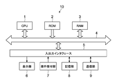
- FIG. 2 is a diagram illustrating a hardware configuration of the control device 10.
- the control device 10 includes a CPU (Central Processing Unit) 1, a ROM (Read Only Memory) 2, a RAM (Random Access Memory) 3, an input / output interface 5, and a bus 4 for connecting them together. Is provided.
- CPU Central Processing Unit
- ROM Read Only Memory
- RAM Random Access Memory
- the CPU 1 appropriately accesses the RAM 3 or the like as necessary, and comprehensively controls each block of the control device 10 while performing various arithmetic processes.
- the ROM 2 is a non-volatile memory in which an OS to be executed by the CPU 1 and firmware such as programs and various parameters are fixedly stored.
- the RAM 3 is used as a work area of the CPU 1 and temporarily holds the OS, various applications being executed, and various data being processed.
- the input / output interface 5 is connected with a display unit 6, an operation receiving unit 7, a storage unit 8, a communication unit 9, and the like.
- the display unit 6 is a display device using, for example, an LCD (Liquid Crystal Display), an OELD (Organic Electro Luminescence Display), a CRT (Cathode Ray Tube), or the like.
- a control screen such as a detection value of the daylighting sensor 18 or the outdoor light sensor 19 or an output value of the LED 17 may be displayed.
- the operation reception unit 7 is, for example, a pointing device such as a mouse, a keyboard, a touch panel, and other input devices.
- the operation reception unit 7 is a touch panel, the touch panel can be integrated with the display unit 6.
- the storage unit 8 is a nonvolatile memory such as a flash memory such as an HDD (Hard Disk Drive) or an SSD (Solid State Drive). In addition to the OS, various applications, and various data, the storage unit 8 stores software programs and data necessary for the dimming control processing in the present embodiment.
- a flash memory such as an HDD (Hard Disk Drive) or an SSD (Solid State Drive).
- HDD Hard Disk Drive
- SSD Solid State Drive
- the data stored in the storage unit 8 includes a light emission surface light amount detected by the daylighting sensor 18, an outdoor light amount detected by the outdoor light sensor 19, and a predetermined period (for example, 1 hour) of the light emission surface light amount detected. And the integrated light amount in 1 day), the cultivation surface light amount (predicted value) calculated based on the light emission surface light amount, the target value of the cultivation surface light amount, and the difference value between the target value and the cultivation surface light amount, every day Data such as power consumption values are included.
- the communication unit 9 is a wireless communication module such as an Ethernet NIC (Network Interface Card) or a wireless LAN, and is used for communication with the LED 17, the daylighting sensor 18, and the outdoor light sensor 19.
- Ethernet NIC Network Interface Card
- wireless LAN wireless local area network
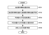
- FIG. 3 is a flowchart showing a schematic flow of dimming control processing by the hydroponic cultivation system.
- the instantaneous light quantity of the light emitting surface 15a is measured by the daylighting sensor 18 (step 31).
- the measured value is transmitted to the control device 10 and stored in the storage unit 8.
- control device 10 predicts the instantaneous light amount of the cultivation surface 12a from the measured instantaneous light amount of the light emitting surface 15a (step 32).
- data (described later) indicating the relationship between the instantaneous light quantity of the cultivation surface 12a and the instantaneous light quantity of the light emission surface 15a is used.
- control device 10 subtracts the predicted value (integrated value) of the light amount of the cultivation surface 12a in a predetermined period (1 hour, 1 day, etc.) from the target value of the light amount of the cultivation surface 12a in the predetermined period,
- the insufficient light amount (complementary light amount) on the cultivation surface 12a is calculated (step 33).
- control device 10 determines the output amount of the LED 17 necessary for irradiating the insufficient light amount based on the insufficient light amount (step 34). For the determination, correlation data (described later) between the complementary light amount of the LED 17 and the output of the LED 17 is used.
- control apparatus 10 controls LED17 to irradiate the seedling V with artificial light (complementary light) according to the determined output value (step 35) (light control process).
- FIG. 4 is a graph showing the relationship between the instantaneous light quantity (PPFD) of the cultivation surface 12a and the instantaneous light quantity (PPFD) of the light emission surface 15a.
- the instantaneous light quantity when the seedling V is irradiated only with sunlight collected by the daylighting device 13 (solid line in the figure), and the instantaneous light quantity when only the artificial light from the LED 17 is irradiated on the seedling V (broken line in the figure). ) And are shown respectively.
- the instantaneous light amount on the cultivation surface 12a is slightly smaller than the instantaneous light amount on the light emitting surface 15a. This is considered to be because light attenuates by the distance between the light emitting surface 15a and the cultivation surface 12a.
- the instantaneous light amount on the cultivation surface 12a is significantly larger than the instantaneous light amount on the light emitting surface 15a. This is considered to be because most of the light emitted from the light emission surface 15a by the LED 17 is repeatedly reflected by the cultivation panel 12 and the acrylic plate 15 and irradiated to the cultivation surface 12a. Therefore, when the reflected light from the cultivation panel 12 and the acrylic board 15 decreases with the growth of the leaves, the inclination of the graph of the LED 17 also decreases.
- the target value of the instantaneous light quantity irradiated to the cultivation surface 12a is set to 100 or 150 (micromol / m ⁇ 2> * s), for example as shown in the figure, the instantaneous light quantity and each target value in the light emission surface 15a are set. Is the complementary light amount by the LED 17.
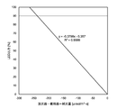
- FIG. 5 is a graph showing the relationship between the complementary light amount and the instantaneous light amount of the light-emitting surface at the time of dimming control.
- FIG. 6 is a graph showing the relationship between the output of the LED 17 and the complementary light amount. As shown in the figure, it can be seen that there is a proportional relationship between the complementary light amount of the LED 17 and its output.
- the control device 10 stores data indicating the relationships shown in FIGS. 4 to 6 in the storage unit 8, and converts the instantaneous light amount of the light emitting surface 15a into the instantaneous light amount (predicted value) of the cultivation surface 12a and This is used to determine the output of the LED 17 when the LED 17 supplements the insufficient light quantity.
- dimming control processing Specific examples include the following four examples.
- ON / OFF control A threshold is provided for the amount of outdoor light, and the LED 17 is turned on when the amount of outdoor light is less than the threshold, and the LED 17 is turned off when the amount of outdoor light exceeds the threshold.
- Target value control The output of the LED 17 is controlled between 0% and 100% so that the light amount of the target cultivation surface 12a always becomes the target value.
- Integrated amount control The shortage of the required accumulated light amount (target value) for the day is supplemented by the LED 17 at night, and the light amount (excess amount) of the daily light amount that exceeds the target value is calculated as the light amount for the next day.
- a threshold is set for the outdoor light quantity or the daylighting sensor installed on the light emitting surface, and when the light quantity becomes less than the threshold value, the LED 17 is turned on, and when the light quantity exceeds the threshold value, the LED 17 is turned off and within one day
- the amount of light on the cultivation surface 12a for each time zone is corrected for excess or deficiency with respect to the required integrated amount (target value for each time zone) in the next time zone, and the integrated light amount (daily target value) required for one day is controlled. To do.
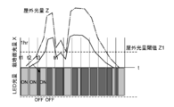
- FIG. 7 and 8 are diagrams conceptually showing the ON / OFF control + integrated amount control.
- the control device 10 turns off the LED 17.
- the outdoor light amount Z may be a value detected by the outdoor light sensor 19.
- the control apparatus 10 grows the excess over the cultivation surface 12a of the next time slot
- the excess or deficiency of the target value H is monitored.
- the target value (X4) when the amount of light on the cultivation surface 12a in a certain time zone falls below the target value (X4), the shortage is added to the target value H of the cultivation surface 12a in the next time zone, and the target value H is exceeded. Monitor for shortages.
- FIG. 9 is a flowchart for explaining the flow of dimming control processing by the ON / OFF control + integrated amount control.
- the (integrated) light amount of the cultivation surface 12a indicates a light amount predicted based on the (integrated) light amount of the light emitting surface 15a as described above.
- control device 10 first sets a daily target integrated light amount on the cultivation surface 12a (step 51).
- control apparatus 10 sets the target integrated light quantity in the cultivation surface 12a of the Nth time (N is the irradiation time (hr) of sunlight in one day) (step 52).
- control device 10 starts control for the first hour (step 53).
- control device 10 controls ON / OFF of the LED 17 according to whether or not the outdoor light quantity is equal to or greater than the threshold value Z1 (step 54).
- the control device 10 turns on the LED 17 regardless of the outdoor light amount Z.
- the sum of the amount of light (sunlight) on the cultivation surface 12 a and the amount of light (artificial light) of the LED 17 exceeded the light saturation point of the seedling V (for example, 400 ⁇ mol / m 2 ⁇ s in the case of lettuce). In this case, the LED 17 is turned off.
- control device 10 calculates the actual accumulated light amount for one hour by multiplying the light amount on the cultivation surface 12a by the ON time of the LED 17 (step 55).
- control device 10 determines whether or not there is a deficiency in the target integrated light quantity for one hour in the above results (step 56).
- control device 10 adds the shortage to the target integrated light amount for the next one hour (step 57).
- control device 10 subtracts the excess from the target light quantity for the next hour (step 58).
- control device 10 determines whether or not the control for the Nth time has been completed (step 59), and repeatedly executes the processing of the above steps 52 to 56 unless the control for the Nth time has been completed. To do.
- the shortage of the light quantity in the cultivation surface 12a is calculated by subtracting the actual value after N hours from the target integrated light quantity of one day. (Step 60).
- the control device 10 sets supplementary light conditions (irradiation time and irradiation time zone) by the LED 17 for the shortage (step 61). Specifically, the control device 10 calculates the irradiation time by dividing the above insufficient light amount by the light amount per unit time at the maximum output of the LED 17, and sets the irradiation time zone, for example, immediately after irradiation for N hours. Set to either time of day or night time.
- control apparatus 10 completes the dimming control process in one day by performing the dimming by LED17 according to the said set dimming conditions, and moves to the dimming control process of the next day (step 62). .
- FIG. 10 is a diagram showing the relationship between the dimming control process for the 1 hour (left side of the figure) and the dimming control process for the day (right side of the figure).
- the control device 10 turns the LED 17 on regardless of the outdoor light quantity Z. Force ON.
- the control device 10 adds the shortage to the target integrated light quantity (X2) in the next one hour, and vice versa 1
- the excess amount is added to the integrated light amount in the next one hour, and the integrated light amount of the cultivation surface 12a is controlled to reach the target integrated light amount at each time. To do.
- FIG. 11 is a flowchart showing a more detailed flow of the dimming control processing of the LED 17 by ON / OFF control + integrated amount control.
- Hs is the target integrated light intensity in 1 hour
- Xs is the instantaneous light intensity of sunlight irradiating the cultivation surface 12a
- Xm is the integrated sunlight light intensity of the sunlight
- Xp is cultivated from the present to the remaining time in 1 hour.
- Ls is the instantaneous light amount of artificial light from the LED 17 irradiated on the cultivation surface 12a
- Lp is irradiated on the cultivation surface 12a from the present to the remaining time in one hour.
- the estimated integrated light amount of the artificial light, and Lm indicate the integrated light amount of the artificial light.
- the figure does not include nighttime dimming control processing that is insufficient for daytime dimming control processing.
- control device 10 inputs a set value and a current time of sunlight irradiation time (time zone) in one day (steps 111 and 112), and whether or not the current time is within the irradiation time. Is determined (step 113).
- control device 10 If it is determined that the current time is within the irradiation time (Yes), the control device 10 starts the dimming control process (step 114).
- the control device 10 executes the light quantity integration process of the LED 17, the sunlight light quantity integration process, and the dimming time control process in parallel.
- control device 10 first turns on the LED 17 (step 115).
- control device 10 sequentially calculates the instantaneous light amount Ls on the cultivation surface 12a based on the instantaneous light amount sequentially input from the LED 17 (step 116), and adds it to the integrated light amount Lm of the LED 17 before that. (Steps 117 and 118).
- the control device 10 sequentially calculates the instantaneous light amount Xs on the cultivation surface 12a based on the instantaneous light amount on the light emitting surface 15a sequentially input from the daylighting sensor 18 (step 119). Is added to the previous daylighting integrated light quantity Xm (steps 120 and 121).
- control device 10 sequentially inputs the scan time from the timer (step 122) and adds it to the previous integrated time tm (steps 123 and 124).
- the control device 10 calculates the predicted light amount Xp of sunlight that is expected to be irradiated in the remaining time from that time point in 1 hour based on the above-described accumulated sunlight light amount Xm and the accumulated time tm by the following formula. (Step 125).
- Predicted light intensity: Xp (Xm ⁇ tm) ⁇ (3600 ⁇ tm) + Xm
- control device 10 calculates the predicted light amount Lp of artificial light that is expected to be irradiated in the remaining time from that point in one hour based on the integrated light amount Lm and the integrated time of the LED 17 by the following formula ( Step 125).
- LED predicted light intensity: Lp 160 ⁇ (3600-tm)
- control device 10 determines whether or not a value (Hs ⁇ Xp) obtained by subtracting the predicted sunlight light amount Xp from the target integrated light amount Hs in the one hour is smaller than the predicted light amount Lp of the artificial light. (Step 126).
- control device 10 turns on the LED 17 (step 127).
- the LED 17 is already ON, the ON state is continued.
- control apparatus 10 judges whether the sum total of each said instantaneous light quantity Xs and Ls of the said sunlight and artificial light is more than an upper limit (light saturation point of the seedling V) (step 128), and it is more than an upper limit. If it is determined (Yes), the LED 17 is turned off (step 129).
- control device 10 determines whether or not one hour to be processed has elapsed (step 130).
- the control device 10 uses the value obtained by subtracting the total light amount integrated value of sunlight and artificial light (Xm + Lm) from the target integrated light amount Hs as a correction amount, and sets the next target time. Is added to the target integrated light amount Hs (n + 1) at (1) to set the target integrated light amount Hs (n + 1) for the next time (step 131). Note that the control device 10 may switch the process at the current time without waiting for one hour to pass depending on the situation.
- control device 10 turns off the LED 17 (step 132), clears the daylighting accumulated light amount Xm and the accumulated time tm to zero, and switches the processing to the next time (step 133).
- the control device 10 executes the above processing until the set irradiation time elapses.
- FIG. 12 is a table showing an implementation result of the dimming control process of the LED 17 by the ON / OFF control + integral amount control shown in FIG. 11, and FIG. 13 shows an implementation result of the dimming control process for one day. It is the graph which showed.
- the target integrated light quantity for 1 day was set to 5 mol / m 2
- the light quantity of the LED 17 at the time of sunlight irradiation was set to 160 ⁇ mol / m 2 ⁇ s.
- the average value of the accumulated light quantity for the shortage of the accumulated light quantity during the day is added as the target accumulated light quantity Hs for each hour of the night, and is compensated by the LED 17. Light is implemented.
- the target integrated light quantity for each hour at night is required to be within 70% of the light quantity of the LED 17 when the LED 17 is continuously energized.
- the control device 10 dynamically performs ON / OFF control of the LED 17 based on the predicted value of the light amount on the cultivation surface 12a at each processing target time, and also with respect to the target integrated light amount for each time. Dimming can be performed by adding the shortage to the target integrated light quantity for the next time. At the same time, the control device 10 can cover the shortage of the integrated light quantity during the day with respect to the target integrated light quantity of the day by supplementing light by the LED 17 at night.
- control apparatus 10 can also perform the growth management process of the seedling V using the daylighting sensor 18 in addition to the various light control processes. Details of the growth management process will be described below.
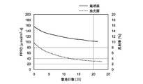
- the reflectance from the cultivation surface 12a decreases as the area of the plant leaf increases (that is, the seedling grows). This is considered to be because the proportion of the leaves that absorb the artificial light emitted from the LED 17 increases as the leaf area increases.
- FIG. 14 is a graph showing the relationship between the amount of light on the cultivation surface 12a and the light emission surface 15a of the artificial light irradiated from the LED 17 and the number of cultivation days of the seedling V. The figure shows values when the output of the LED 17 is set to 50%.
- the amount of light decreases as the number of cultivation days elapses (that is, the leaves of the seedling V become larger) on both the light emitting surface 15a and the cultivation surface 12a. This is considered to be because the reflected light from the cultivation panel 12 or the acrylic board 15 of the artificial light irradiated from the LED 17 decreases due to the growth of the leaves. Therefore, it is considered that a larger amount of light supplemented by the LED 17 is required as the leaves grow.
- the control device 10 uses the daylighting sensor 18 to irradiate a certain amount of the LED 17 in the time zone (nighttime) when there is no sunlight, and measures the reflected light from the cultivation surface 12a, thereby It has a mechanism for determining whether the amount of reflected light at each growth time of V is secured and thereby adjusting the output of the LED 17.
- control apparatus 10 utilizes the positional relationship that the cultivation panel 12 is provided facing in the horizontal direction with the pair of light emitting surfaces 15a facing each other in the horizontal direction. Is used for detecting the amount of sunlight irradiated to the seedlings V of the cultivation panel facing the light emitting surface 15a, and the light emission side opposite to the light emitting surface 15a is used. It is also used for detecting reflected light of artificial light irradiated from the LED 17 on the light surface 15a to the seedlings V of the cultivation panel facing the light emission surface 15a, whereby the growth management processing of the seedlings V can be executed. .
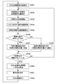
- FIG. 15 is a flowchart showing the flow of growth management processing using the amount of reflected light of the leaves.
- the control device 10 holds reference data regarding the reflectance (the amount of reflected light) according to the number of days of cultivation of the leaves in the storage unit 8.
- the control device 10 sends artificial light from the LED 17 to the cultivation panel 12 facing the light emitting surface 15a (acrylic plate 15) provided with the LED 17 in a time zone (such as nighttime) when there is no sunshine. Irradiate (step 161).
- This artificial light irradiation may be executed as a supplementary light processing by the LED 17 in the dimming control processing, or may be executed separately.
- control device 10 uses the daylighting sensor 18 provided on the light emission surface 15a (acrylic plate 15) facing the light emission surface 15a (acrylic plate 15) provided with the LED 17 to transmit the irradiated artificial light.
- a measurement value of the amount of reflected light is acquired (step 162).
- the control device 10 determines whether or not the measured value of the reflected light is within a predetermined range in light of the reference data (step 163). For example, if the reflected light amount on the x-th day in the reference data is 50 ⁇ mol / m 2 ⁇ s, if the measured reflected light amount is within ⁇ 5%, it is within the reference range, otherwise Is judged to be outside the reference range.
- control device 10 increases the daily target integrated light amount of the artificial light irradiated by the LED 17 by a predetermined ratio (for example, 10%) (step 164). ).
- control apparatus 10 grasps
- the hydroponic cultivation system irradiates from the LED 17 based on the amount of sunlight irradiated to the cultivation surface 12a (a value predicted from the amount of light emitted from the light emitting surface 15a).
- the irradiation amount of artificial light it is possible to stably produce seedlings V without variation in the growth of seedlings V when cultivating only with sunlight, and artificial light is irradiated as needed.
- the power cost for light illumination can be reduced.
- control device 10 compares the transition of the amount of sunlight detected by the daylighting sensor 18 with the transition of the amount of sunlight detected by the outdoor light sensor 19, and correlates both. When it is determined that there is no error, information indicating abnormality may be output.
- the control device 10 when it is detected that the light amount of the light emitting surface 15a that is normally interlocked with the outdoor light is not interlocked with the outdoor light, the control device 10 outputs the abnormality information to thereby perform the dimming control process. Accuracy can be improved.
- the cause of the correlation between the two transitions being lost for example, direct light is applied to the daylighting sensor 18 or the amount of the daylighting is reduced due to the shadow of the seedling V or a person.
- the user of the hydroponic cultivation system can take such abnormality information and take measures such as adjusting the position of the daylighting sensor 18.
- the control device 10 analyzes the output from each daylighting sensor 18, identifies the daylighting sensor 18 outputting an abnormal value, and outputs at least the output from the daylighting sensor 18. You may control automatically not to use for a light control process for a fixed period.
- the LED 17 is used as the artificial light irradiation device, but the artificial light irradiation device is not limited thereto, and for example, a fluorescent lamp, an organic light emitting diode (OLED), or the like may be used.
- a fluorescent lamp for example, an organic light emitting diode (OLED), or the like may be used.
- OLED organic light emitting diode
- the dimming control process is executed in units of 1 hour and 1 day, but the control unit is not limited to these, and the unit may be changed as appropriate.
- the light emitting surface 15a is provided as each outer surface of the pair of acrylic plates 15.
- the light emitting surface 15a is not necessarily provided on the acrylic plate, and is a member of the daylighting device 13. What is necessary is just to be provided in either.
- control apparatus 10 is separated from the plant factory.
- the server may be provided as a server on the Internet (on the cloud).
- the plant factory exchanges data necessary for the dimming control processing such as the detection value of the daylighting sensor 19, the output value of the LED 17, or the ON / OFF command with the control device 10 on the Internet.
- a control panel or a computer for relaying may be provided.
Landscapes
- Life Sciences & Earth Sciences (AREA)
- Environmental Sciences (AREA)
- Biodiversity & Conservation Biology (AREA)
- Botany (AREA)
- Ecology (AREA)
- Forests & Forestry (AREA)
- Cultivation Of Plants (AREA)
- Hydroponics (AREA)
Abstract
水耕栽培システムは、水耕栽培ユニットと、採光装置と、人工光照射装置と、採光センサと、制御装置とを有する。上記水耕栽培ユニットは、栽培対象の植物の苗が移植される苗床が配置されたものである。上記採光装置は、上記苗床に対向する放光面に採光口から自然光を採り入れて上記放光面から上記苗に出射させる。上記人工光照射装置は、上記苗に人工光を照射する。上記採光センサは、上記苗床から離間した位置に設けられ、上記放光面から出射する上記自然光の光量を検出する。上記制御装置は、上記検出された光量を基に、上記苗床の上記苗の栽培面に照射される上記自然光の光量の予測値を算出し、当該予測値に基づいて、上記人工光の照射量を制御する。
Description
本発明は、採光装置によって採り入れた自然光と人工光とを併用した水耕栽培システム、当該水耕栽培システムに用いられる水耕栽培制御装置、水耕栽培方法、及びプログラムに関する。
従来から、水耕栽培を利用して野菜等の植物を屋内で栽培する水耕栽培システムが実用化されている。そのような水耕栽培システムにおいては、人工光のみを利用する栽培方式と、自然光(太陽光)と人工光とを併用する栽培方式とが存在する。
後者に関して、下記特許文献1には、植物栽培ハウス内の閉鎖空間である生育室に、養液循環手段が設けられた複数段の植物栽培棚を設け、当該植物栽培棚の上方に、ランプ、LED等の人工光源を設けるとともに、植物栽培ハウスの屋根の上方に設けられた採光装置によって太陽光を集光し、それを複数の反射鏡によって植物栽培棚に向けて照射する植物工場が開示されている。
しかしながら、上記特許文献1に記載の技術では、採光装置によって採光される太陽光は、天気によってその強度が異なるため、栽培物の成長にばらつきが生じてしまう。
一方で、人工光によって必要以上に補光すると、それが栽培物の生長に寄与せずに電力が無駄になってしまう。
以上のような事情に鑑み、本発明の目的は、栽培物の生長のばらつきを防止して安定的に生産できるとともに、人工光の照明用の電力コストを削減することが可能な水耕栽培システム、水耕栽培制御装置、水耕栽培方法及びプログラムを提供することにある。
上記目的を達成するため、本発明の一形態に係る水耕栽培システムは、水耕栽培ユニットと、採光装置と、人工光照射装置と、採光センサと、制御装置とを有する。上記水耕栽培ユニットは、栽培対象の植物の苗が移植される苗床が配置されたものである。上記採光装置は、上記苗床に対向する放光面に採光口から自然光を採り入れて上記放光面から上記苗に出射させする。上記人工光照射装置は、上記苗に人工光を照射する。上記採光センサは、上記苗床から離間した位置に設けられ、上記放光面から出射する上記自然光の光量を検出する。上記制御装置は、上記検出された光量を基に、上記苗床の上記苗の栽培面に照射される上記自然光の光量の予測値を算出し、当該予測値に基づいて、上記人工光の照射量を制御する。
これにより栽培システムは、栽培面に照射される自然光の光量の予測値を基に人工光の照射量を制御することで、自然光のみで栽培する場合の栽培物の生長のばらつきを防止して安定的に生産できるとともに、必要に応じて人工光を照射することで人工光の照明用の電力コストを削減することができる。
上記制御装置は、所定期間における上記予測値の積算値の和が所定の目標瞬時光量(瞬時値:単位μmol/m2・s)となるように上記所定期間における上記人工光の照射量を制御してもよい。
これにより水耕栽培システムは、目標瞬時光量を設定することで栽培物をより安定的に生産することができる。上記所定期間は例えば1時間でもよいし1日でもよい。
上記採光センサは、上記放光面に設けられてもよい。
これにより水耕栽培システムは、採光センサを、自然光が栽培面に照射される直前の放光面に設けることで、屋外等に設けられる場合に比べてより正確に栽培面の光量を予測することができる。
上記人工光照射装置は、上記放光面に設けられてもよい。この場合上記採光センサは、上記放光面の上記人工光の影響を受けない位置に設けられてもよい。
これにより水耕栽培システムは、人工光の照射中も人工光の影響を受けることなく放光面の自然光の光量を検出し栽培面の光量を予測することができる。
上記苗床は、水平方向で互いに逆向きに設けられた一対の放光面を挟んで上記水平方向で対向して設けられてもよい。この場合上記採光センサは、上記自然光の非照射時において、当該採光センサが設けられた放光面とは別の放光面に設けられた上記人工光照射装置から上記苗に照射された人工光の反射光の光量を検出可能であってもよい。またこの場合上記制御装置は、上記検出された反射光の光量の推移を基に、上記人工光の照射量を制御してもよい。
一般に、苗が成長して葉の面積が大きくなると、葉が光を吸収するために反射率は低下する。したがって水耕栽培システムは、採光センサにより、放光面から照射される自然光の光量を検出するだけでなく、その放光面とは反対側の放光面から苗に照射された人工光の反射光の推移を検出することで、苗の生長度合を把握し、それに応じて人工光の照射量を制御することで苗の生長を管理することができる。
また、苗の生長度合は、苗床の反射率と葉の反射率も関係している。
一般に、苗床の反射率が葉の反射率よりも高い場合、葉の生長に伴って苗床から反射する光が減少し、苗床の反射率が低い場合は、葉が生長するに従って、葉から反射する光の量が増加するので、採光センサで検出する反射光が増加する。
一般に、苗床の反射率が葉の反射率よりも高い場合、葉の生長に伴って苗床から反射する光が減少し、苗床の反射率が低い場合は、葉が生長するに従って、葉から反射する光の量が増加するので、採光センサで検出する反射光が増加する。
従って、目標の葉面積に達している場合の反射光を基準としたとき、苗床が葉の反射率よりも高い場合、葉の生長が遅れていると苗床から反射する光が増加するので、基準の反射光よりも高い数値が検出される。
また、苗床の反射率が葉の反射率よりも低い場合は、葉の生長が遅れていると葉から反射する光の量が減少するので、基準の反射光よりも低い数値が検出される。
このように、反射率を考慮したうえで、採光センサで検出する反射光と目標の葉面積に達している場合の基準の反射光との誤差を判断し、葉の生長を管理することができる。
このように、反射率を考慮したうえで、採光センサで検出する反射光と目標の葉面積に達している場合の基準の反射光との誤差を判断し、葉の生長を管理することができる。
上記水耕栽培システムは、屋外の自然光の光量を検出する屋外光センサをさらに有してもよい。この場合上記制御装置は、上記採光センサによって検出された自然光の光量の推移と上記屋外光センサによって検出された自然光の光量の推移とに相関が無いと判断された場合に、異常を示す情報を出力してもよい。
これにより水耕栽培システムは、通常は屋外光と連動する放光面の光量が屋外光と連動していないことが検出された場合には、異常情報を出力することで、照射量制御の精度を向上させることができる。ここで上記両推移に相関が無くなる原因としては、例えば採光センサに直射光が当たったり、苗や人の影になって採光量が減少したり等の事態が想定される。
本発明の他の形態に係る水耕栽培システムは、水耕栽培ユニットと、採光装置と、人工光照射装置と、採光センサとを有する。上記水耕栽培ユニットは、栽培対象の植物の苗が移植される苗床が配置されたものである。上記採光装置は、上記苗床に対向する放光面に採光口から自然光を採り入れて上記放光面から上記苗に出射させる。上記人工光照射装置は、上記苗に人工光を照射する。上記採光センサは、上記放光面の上記人工光の影響を受けない位置に設けられ、上記放光面から出射する上記自然光の光量を、上記人工光の照射量の制御のために検出する。
本発明のまた別の形態に係る水耕栽培制御装置は、受信部と制御部とを有する。上記受信部は、栽培対象の植物の苗が移植される苗床から離間した位置に設けられた採光センサから、上記苗床に対向する放光面に採光口から採り入れられて当該放光面から上記苗に出射する自然光の光量の検出値を受信する。上記制御部は、上記受信された検出値を基に、上記苗床の上記苗の栽培面に照射される上記自然光の光量の予測値を算出し、当該予測値に基づいて、上記苗に照射される人工光の照射量を制御する。
本発明のまた別の形態に係る水耕栽培方法は、
水耕栽培ユニットに、栽培対象の植物の苗が移植される苗床を配置し、
上記苗床に対向する放光面に外部から自然光を採り入れて上記放光面から上記苗に出射させ、
上記苗床から離間した位置に設けられた採光センサによって検出された、上記放光面から出射する上記自然光の光量を基に、上記苗床の上記苗の栽培面に照射される上記自然光の光量の予測値を算出し、
上記予測値に基づいて、上記苗に照射される人工光の照射量を制御することを含む。
水耕栽培ユニットに、栽培対象の植物の苗が移植される苗床を配置し、
上記苗床に対向する放光面に外部から自然光を採り入れて上記放光面から上記苗に出射させ、
上記苗床から離間した位置に設けられた採光センサによって検出された、上記放光面から出射する上記自然光の光量を基に、上記苗床の上記苗の栽培面に照射される上記自然光の光量の予測値を算出し、
上記予測値に基づいて、上記苗に照射される人工光の照射量を制御することを含む。
本発明のさらに別の形態に係るプログラムは、水耕栽培制御装置に、
栽培対象の植物の苗が移植される苗床から離間した位置に設けられた採光センサから、上記苗床に対向する放光面に採光口から採り入れられて当該放光面から上記苗に出射する自然光の光量の検出値を受信するステップと、
上記受信された検出値を基に、上記苗床の上記苗の栽培面に照射される上記自然光の光量の予測値を算出するステップと、
上記予測値に基づいて、上記苗に照射される人工光の照射量を制御するステップとを実行させる。
栽培対象の植物の苗が移植される苗床から離間した位置に設けられた採光センサから、上記苗床に対向する放光面に採光口から採り入れられて当該放光面から上記苗に出射する自然光の光量の検出値を受信するステップと、
上記受信された検出値を基に、上記苗床の上記苗の栽培面に照射される上記自然光の光量の予測値を算出するステップと、
上記予測値に基づいて、上記苗に照射される人工光の照射量を制御するステップとを実行させる。
以上説明したように、本発明によれば、栽培物の生長のばらつきを防止して安定的に生産できるとともに、人工光の照明用の電力コストを削減することができる。しかし、当該効果は本発明を限定するものではない。
以下、図面を参照しながら、本発明の実施形態を説明する。
[システムの構成]
図1は、本実施形態に係る水耕栽培システムの構成を横断面から示した図である。
図1は、本実施形態に係る水耕栽培システムの構成を横断面から示した図である。
この水耕栽培システムは、レタス、グリーンリーフ、サラダ菜、ミズ菜、ホウレンソウ、ハーブ類等の葉物野菜等の植物を栽培するためのシステムである。
同図に示すように、水耕栽培システム100は、制御装置10と、水耕栽培ユニット11と、採光装置13とを有し、これらは植物工場内に設けられる。
水耕栽培ユニット11は、苗床で種から育てられた、栽培対象の上記葉物野菜の苗Vが移植された栽培パネル12を有する。栽培パネル12は水耕栽培ユニット11において縦(垂直方向)に配置されている。栽培パネル12は、苗が移植される苗床の一例である。苗床は、栽培パネル12のようなパネル状のもの以外に、例えば筒状とされてもよい。
栽培パネル12としては、例えば、ポリスチレン、ポリプロピレン、ポリエチレン、ポリウレタン等の合成樹脂からなるボード(発砲ボードを含む)、植物繊維、樹脂繊維、無機繊維等の繊維素材からなる繊維ボード、及び木材等が用いられるが、軽量であるとともに、生育した苗Vの重さに耐え得る強度を有していれば得に限定されない。
栽培パネル12の形状は特に限定されず、板、柱、筒、棚田状、傾斜など、植物の苗を保持することが可能であればよい。
栽培パネル12の形状は特に限定されず、板、柱、筒、棚田状、傾斜など、植物の苗を保持することが可能であればよい。
栽培パネル12には、移植された苗Vを保持する複数の植え付け孔(図示せず)が穿設されており、当該植え付け孔は、苗Vの収穫期の大きさを考慮した適切な間隔で配列されている。
栽培パネル12の一方の面は栽培面12aとされ、他方の面は液肥供給面とされる。液肥(固形又は液状の肥料を水に溶かした液体肥料)Lは、液肥タンク20からポンプ21によって液肥供給パイプ22を介して液肥供給口23まで供給され、当該液肥供給口23から液肥供給面を伝わって苗Vの根に行き渡るようになっている。
採光装置13は、自然光(太陽光)を取り入れることが可能な構造であればよく、光ダクト、天窓などが用いられる。太陽光追尾装置、ルーバーなどを備えていてもよい。例えば、光ダクトとして構成される場合、自然光(太陽光)を採り入れる採光口14と、水平方向で対向する一対のアクリル板15と、採光口14とアクリル板15の間に設けられた拡散板16を有する。
アクリル板15の素材はアクリルに限定されず、ポリカーボネート、ビニールなど透明な素材であればよい。また、アクリル板15の形状は板状に限定されず、フィルム状など種々の形状のものが用いられる。このアクリル板等の透明仕切りは、栽培空間の空調効率を向上させるために設置することが好ましいが、作業性やコスト面を考慮して設置しなくてもよい。
アクリル板15の素材はアクリルに限定されず、ポリカーボネート、ビニールなど透明な素材であればよい。また、アクリル板15の形状は板状に限定されず、フィルム状など種々の形状のものが用いられる。このアクリル板等の透明仕切りは、栽培空間の空調効率を向上させるために設置することが好ましいが、作業性やコスト面を考慮して設置しなくてもよい。
採光口14から採り入れられた太陽光は、拡散板16によって拡散され、アクリル板15の間で反射を繰り返しながら、アクリル板15の外側の面(放光面15a)から放光(出射)され栽培パネル12の苗Vに照射される。一対のアクリル板15の各放光面15aは、水平方向で互いに逆向きに設けられている。
また、上記栽培パネル12は、上記一対のアクリル板15を挟んで地面と水平方向で対向して設けられている。
アクリル板15の放光面15aには、上記苗Vに人工光を照射する人工光照射装置としてのLED17が設けられている。当該LEDは、上記苗Vに対して照射される光が、太陽光のみでは所定の目標値に達しない場合に、上記太陽光を補光する役割を担う。
当該LED17による補光は、採光装置13による放光面15aからの太陽光の照射と並行して実行されるほか、太陽光が照射されない夜間においても行われる。
また同じくアクリル板15の放光面15aには、当該放光面15aから出射した太陽光の光量を検出する採光センサ18が設けられている。当該採光センサ18は、上記栽培パネルから離間した位置であって、同じ放光面15aに設けられたLED17から照射される人工光の影響を受けない位置、例えば採光センサ18の受光部がアクリル板15側を向いており、同じ放光面15aに設けられたLED17から照射される人工光を受光しない位置に配置されている。
また水耕栽培ユニット11の外部には、屋外の自然光(太陽光)の光量を検出する屋外光センサ19が設けられている。
制御装置10は、上記LED17及び上記採光センサ18と接続されている。制御装置10は、上記採光センサ18によって検出された放光面15aにおける太陽光の光量を受信し、当該検出された太陽光の光量を基に、栽培パネル12の苗Vの栽培面12aに照射される太陽光の光量の予測値を算出する。そして制御装置10は、当該予測値に基づいて、LED17から照射される人工光の照射量を制御することが可能である(以下、この制御を調光制御処理ともいう)。具体的には、制御装置10は、所定期間(1時間、1日等)における、栽培面12aの光量の予測値の積算値との和が所定の目標瞬時光量となるように、当該所定期間におけるLED17からの人工光の照射量を制御する。当該調光制御処理の詳細については後述する。
また制御装置10は、上記ポンプ21にも接続され、液肥の供給及び供給量を制御する。また制御装置10は上記屋外光センサ19にも接続され、屋外光センサ19によって検出された屋外光の光量を受信する。
詳細は後述するが、制御装置10は、上記採光センサ18によって検出された太陽光の光量の推移と、上記屋外光センサ19によって検出された太陽光の光量の推移とを比較して、それらの間に相関が無いと判断された場合に、異常を示す情報を出力することも可能である。
また上記採光センサ18は、上記自然光の非照射時(例えば夜間や雨天時)において、当該採光センサ18が設けられたアクリル板15に対向するもう一方のアクリル板15の放光面15aに設けられたLED17から苗Vに照射された人工光の反射光の光量を検出することも可能である。
そして、詳細は後述するが、上記制御装置10は、当該検出された反射光の光量の推移を基に、苗Vの生長度合を把握し、それに応じてLED17から照射される人工光の照射量を制御することも可能である。
[制御装置のハードウェア構成]
図2は、上記制御装置10のハードウェア構成を示した図である。同図に示すように、制御装置10は、CPU(Central Processing Unit)1、ROM(Read Only Memory)2、RAM(Random Access Memory)3、入出力インタフェース5、及び、これらを互いに接続するバス4を備える。
図2は、上記制御装置10のハードウェア構成を示した図である。同図に示すように、制御装置10は、CPU(Central Processing Unit)1、ROM(Read Only Memory)2、RAM(Random Access Memory)3、入出力インタフェース5、及び、これらを互いに接続するバス4を備える。
CPU1は、必要に応じてRAM3等に適宜アクセスし、各種演算処理を行いながら制御装置10の各ブロック全体を統括的に制御する。ROM2は、CPU1に実行させるOS、プログラムや各種パラメータなどのファームウェアが固定的に記憶されている不揮発性のメモリである。RAM3は、CPU1の作業用領域等として用いられ、OS、実行中の各種アプリケーション、処理中の各種データを一時的に保持する。
入出力インタフェース5には、表示部6、操作受付部7、記憶部8、通信部9等が接続される。
表示部6は、例えばLCD(Liquid Crystal Display)、OELD(Organic Electro Luminescence Display)、CRT(Cathode Ray Tube)等を用いた表示デバイスである。表示部6には、例えば上記採光センサ18や屋外光センサ19の検出値や、LED17の出力値等の制御画面等が表示されてもよい。
操作受付部7は、例えばマウス等のポインティングデバイス、キーボード、タッチパネル、その他の入力装置である。操作受付部7がタッチパネルである場合、そのタッチパネルは表示部6と一体となり得る。
記憶部8は、例えばHDD(Hard Disk Drive)や、SSD(Solid State Drive)等のフラッシュメモリ等の不揮発性メモリである。当該記憶部8には、上記OSや各種アプリケーション、各種データに加えて、本実施形態における調光制御処理に必要なソフトウェアプログラム及びデータが記憶される。
記憶部8に記憶されるデータには、上記採光センサ18で検出された放光面光量、屋外光センサ19で検出された屋外光量、上記検出された放光面光量の所定期間(例えば1時間及び1日)における積算光量、当該放光面光量を基に算出された栽培面光量(予測値)、当該栽培面光量の目標値、及び目標値と栽培面光量との差分値、1日毎の使用電力値等のデータが含まれる。
通信部9は、例えばEthernet用のNIC(Network Interface Card)や無線LAN等の無線通信用の各種モジュールであり、上記LED17、採光センサ18、屋外光センサ19との間の通信に用いられる。
[水耕栽培システムの動作]
次に、以上のように構成された水耕栽培システム100の動作について説明する。当該動作は、上記制御装置10のCPU1等のハードウェアと、記憶部8に記憶されたソフトウェア、及び制御装置10に接続されたLED17、採光センサ18、屋外光センサ19との協働により実行される。
次に、以上のように構成された水耕栽培システム100の動作について説明する。当該動作は、上記制御装置10のCPU1等のハードウェアと、記憶部8に記憶されたソフトウェア、及び制御装置10に接続されたLED17、採光センサ18、屋外光センサ19との協働により実行される。
図3は、上記水耕栽培システムによる調光制御処理の概略的な流れを示したフローチャートである。
同図に示すように、まず、上記採光センサ18により、放光面15aの瞬時光量が測定される(ステップ31)。当該測定値は、制御装置10へ送信され記憶部8に記憶される。
続いて制御装置10は、上記測定された放光面15aの瞬時光量から、栽培面12aの瞬時光量を予測する(ステップ32)。当該予測処理には、栽培面12aの瞬時光量と放光面15aの瞬時光量との関係を示すデータ(後述)が用いられる。
続いて制御装置10は、所定期間(1時間、1日等)における上記栽培面12aの光量の予測値(積算値)を、当該所定期間における栽培面12aの光量の目標値から減ずることで、栽培面12aにおける不足光量(補光量)を算出する(ステップ33)。
続いて制御装置10は、上記不足光量を基に、当該不足光量を照射するのに必要なLED17の出力量を決定する(ステップ34)。当該決定には、LED17による補光量とLED17の出力との相関データ(後述)が用いられる。
そして制御装置10は、上記決定した出力値によって苗Vに人工光を照射(補光)するようLED17を制御する(ステップ35)(調光制御処理)。
図4は、上記栽培面12aの瞬時光量(PPFD)と放光面15aの瞬時光量(PPFD)との関係を示したグラフである。同図では、採光装置13によって採光される太陽光のみを苗Vに照射した場合の瞬時光量(同図実線)と、LED17の人工光のみを苗Vに照射した場合の瞬時光量(同図破線)とがそれぞれ示されている。
同図に示すように、太陽光のみが照射される場合、栽培面12aにおける瞬時光量は、放光面15aにおける瞬時光量よりもやや少なくなっている。これは、放光面15aと栽培面12aとの距離の分だけ光が減衰するためであると考えられる。
一方、LED17の人工光のみが照射される場合、栽培面12aにおける瞬時光量は、放光面15aにおける瞬時光量よりも著しく大きくなっている。これは、LED17によって放光面15aから照射される光のほとんどが栽培パネル12やアクリル板15によって繰り返し反射されて栽培面12aに照射されるためであると考えられる。したがって、葉の生長に伴い、栽培パネル12やアクリル板15からの反射光が減少すると、LED17のグラフの傾きも減少する。
そして、同図に示すように、栽培面12aに照射される瞬時光量の目標値が例えば100または150(μmol/m2・s)に設定される場合、放光面15aにおける瞬時光量と各目標値との差が、上記LED17による補光量となる。
図5は、調光制御時における上記補光量と放光面の瞬時光量との関係を示したグラフである。同図に示すように、調光制御時においては、目標値が例えば100μmol/m2・sと150μmol/m2・sのいずれに設定される場合でも、放光面15aにおける瞬時光量Xと補光量Yとの関係は、Y=X-目標値で表されることが分かる。
図6は、上記LED17の出力と補光量との関係を示したグラフである。同図に示すように、LED17の補光量とその出力とには比例関係があることが分かる。
制御装置10は、これら図4~図6に示した各関係を示すデータを記憶部8に記憶し、上記放光面15aの瞬時光量から栽培面12aの瞬時光量(予測値)への換算及びLED17による不足光量の補光時のLED17の出力の決定に用いる。
[調光制御処理の具体例]
上記調光制御処理の具体的な手法としては、例えば以下の4つの例が挙げられる。
(1)ON/OFF制御:
屋外光量に閾値を設け、屋外光量が閾値未満になった場合にLED17をONにし、屋外光量が閾値以上になった場合にLED17をOFFにする。
(2)目標値制御:
目標の栽培面12aの光量が常に目標値となるように、LED17の出力を0%~100%との間で制御する。
(3)積算量制御:
1日の必要積算光量(目標値)の不足分を、夜間にLED17によって補光し、1日の光量のうち目標値を上回った光量(過剰分)は、次の日の光量として計算する。
(4)ON/OFF制御+積算量制御:
屋外光量もしくは放光面に設置した採光センサに閾値を設け、光量が閾値未満になった場合にLED17をONにし、光量が閾値以上になった場合にLED17をOFFにするとともに、1日のうちの時間帯毎に栽培面12aの光量の必要積算量(時間帯毎の目標値)に対する過不足を次の時間帯で補正し、一日に必要な積算光量(一日の目標値)を制御する。
上記調光制御処理の具体的な手法としては、例えば以下の4つの例が挙げられる。
(1)ON/OFF制御:
屋外光量に閾値を設け、屋外光量が閾値未満になった場合にLED17をONにし、屋外光量が閾値以上になった場合にLED17をOFFにする。
(2)目標値制御:
目標の栽培面12aの光量が常に目標値となるように、LED17の出力を0%~100%との間で制御する。
(3)積算量制御:
1日の必要積算光量(目標値)の不足分を、夜間にLED17によって補光し、1日の光量のうち目標値を上回った光量(過剰分)は、次の日の光量として計算する。
(4)ON/OFF制御+積算量制御:
屋外光量もしくは放光面に設置した採光センサに閾値を設け、光量が閾値未満になった場合にLED17をONにし、光量が閾値以上になった場合にLED17をOFFにするとともに、1日のうちの時間帯毎に栽培面12aの光量の必要積算量(時間帯毎の目標値)に対する過不足を次の時間帯で補正し、一日に必要な積算光量(一日の目標値)を制御する。
本実施形態では、これらの手法のうち、(4)ON/OFF制御+積算量制御について説明する。
図7及び図8は、当該ON/OFF制御+積算量制御を概念的に示した図である。
図7に示すように、制御装置10は、採光センサ18によって検出された屋外光量Zが閾値Z1以上となった場合(同図t3)には、LED17をOFFにする。
屋外光量Zは屋外光センサ19によって検出された値でもよい。
屋外光量Zは屋外光センサ19によって検出された値でもよい。
また制御装置10は、図8に示すように、ある時間帯における栽培面12aにおける光量が目標値Hを上回った場合(X2、X3)には、その過剰分を次の時間帯の栽培面12aの光量として加算して目標値Hの過不足を監視する。
同様に、ある時間帯における栽培面12aにおける光量が目標値を下回った場合(X4)は、その不足分を次の時間帯の栽培面12aの目標値Hに加算して、目標値Hの過不足を監視する。
同様に、ある時間帯における栽培面12aにおける光量が目標値を下回った場合(X4)は、その不足分を次の時間帯の栽培面12aの目標値Hに加算して、目標値Hの過不足を監視する。
図9は、当該ON/OFF制御+積算量制御による調光制御処理の流れを説明したフローチャートである。以下の説明において、栽培面12aの(積算)光量とは、上述したように放光面15aの(積算)光量を基に予測された光量を指す。
同図に示すように、制御装置10は、まず、栽培面12aにおける1日の目標積算光量を設定する(ステップ51)。
続いて制御装置10は、N時間目(Nは1日のうちの太陽光の照射時間(hr))の栽培面12aにおける目標積算光量を設定する(ステップ52)。
続いて制御装置10は、1時間目の制御を開始する(ステップ53)。
続いて制御装置10は、LED17を、屋外光量が閾値Z1以上か否かに応じてON/OFF制御する(ステップ54)。
この際、制御装置10は、栽培面12aの光量がN時間における目標積算光量(累積値)を下回った場合には、屋外光量Zに関わらずLED17をONにする。また制御装置10は、栽培面12aの光量(太陽光)とLED17の光量(人工光)との合計が、苗Vの光飽和点(例えばレタスの場合には400μmol/m2・s)を上回った場合には、LED17をOFFにする。
続いて制御装置10は、栽培面12aにおける光量に、LED17のON時間を乗じることで、1時間の積算光量の実績を算出する(ステップ55)。
続いて制御装置10は、上記実績において、1時間の目標積算光量に不足が存在するか否かを判断する(ステップ56)。
上記目標積算光量に不足が存在していると判断した場合(Yes)、制御装置10は、その不足分を次の1時間の目標積算光量に加算する(ステップ57)。
一方、上記目標積算光量に超過が生じていると判断した場合(No)、制御装置10は、当該超過分を次の1時間の目標光量から減算する(ステップ58)。
続いて制御装置10は、N時間目の制御が完了したか否かを判断し(ステップ59)、当該N時間目の制御が完了していない限り以上のステップ52~56の処理を、繰り返し実行する。
そして制御装置10は、N時間目の制御が完了したと判断した場合(Yes)、1日の目標積算光量からN時間後の実績値を減じることで、栽培面12aにおける光量の不足分を算出する(ステップ60)。
続いて制御装置10は、上記不足分について、LED17による補光条件(照射時間及び照射時間帯)を設定する(ステップ61)。具体的には、制御装置10は、上記不足分の光量をLED17の最大出力時の単位時間当たりの光量で除することで照射時間を算出し、照射時間帯を、例えばN時間の照射直後の時間帯または夜間のいずれかの時間帯に設定する。
そして制御装置10は、上記設定された補光条件に従ってLED17による補光を実行することで、1日における調光制御処理を完了し、次の日の調光制御処理へと移る(ステップ62)。
図10は、上記1時間における調光制御処理(同図左側)と1日における調光制御処理(同図右側)との関係を示した図である。
同図左側に示すように、制御装置10は、ある1時間において、栽培面12aの積算光量が目標積算光量(同図破線で示す)を下回った場合には、屋外光量Zに関わらずLED17を強制的にONにする。
また制御装置10は、ある1時間における目標積算光量(X1)に不足分が発生した場合には、当該不足分を次の1時間における目標積算光量(X2)に追加し、また逆にある1時間において目標積算光量からの過剰分が発生した場合には、当該過剰分を次の1時間における積算光量に加算して、各時間で栽培面12aの積算光量が目標積算光量に達するように制御する。
しかし、同図右側に示すように、当該1時間毎の制御によって1日の目標積算光量Hに不足分が発生した場合には、上述したように、当該不足分に応じて、LED17による補光の照射時間及び照射時間帯を決定して、補光を実行する。
図11は、ON/OFF制御+積算量制御によるLED17の調光制御処理のさらに詳細な流れを示したフローチャートである。
同図において、Hsは1時間における目標積算光量、Xsは栽培面12aに照射される太陽光瞬時光量、Xmは当該太陽光の採光積算光量、Xpは1時間のうち現在から残り時間までに栽培面12aに照射が見込まれる当該太陽光の予測積算光量、Lsは栽培面12aに照射されるLED17からの人工光の瞬時光量、Lpは1時間のうち現在から残り時間までに栽培面12aに照射が見込まれる上記人工光の予測積算光量、Lmは上記人工光の積算光量をそれぞれ指す。
また同図においては、日中の調光制御処理で不足した分の夜間における調光制御処理は含まれていない。
同図に示すように、制御装置10は、1日における太陽光の照射時間(時間帯)の設定値及び現在時刻をそれぞれ入力し(ステップ111、112)、現在時刻が照射時間内か否かを判断する(ステップ113)。
現在時刻が照射時間内であると判断した場合(Yes)、制御装置10は、調光制御処理を開始する(ステップ114)。
当該調光制御処理の開始に伴い、制御装置10は、LED17の光量積算処理と、太陽光の光量積算処理と、調光時間の制御処理とを並行して実行する。
LED17の光量積算処理において、制御装置10はまず、LED17をONにする(ステップ115)。
続いて制御装置10は、LED17から逐次入力される瞬時光量を基に、栽培面12aにおける瞬時光量Lsを逐次算出し(ステップ116)、それをそれ以前のLED17の積算光量Lmに加算していく(ステップ117、118)。
また太陽光の光量積算処理において、制御装置10は、採光センサ18から逐次入力される放光面15aにおける瞬時光量を基に、栽培面12aにおける瞬時光量Xsを逐次算出し(ステップ119)、それをそれ以前の太陽光の採光積算光量Xmに加算していく(ステップ120、121)。
また調光時間の制御処理において、制御装置10は、タイマーからのスキャンタイムを逐次入力して(ステップ122)、それをそれ以前の積算時間tmに加算していく(ステップ123、124)。
続いて制御装置10は、上記太陽光の採光積算光量Xmと積算時間tmを基に、1時間におけるその時点からの残り時間に照射が見込まれる太陽光の予測光量Xpを、以下の式によって算出する(ステップ125)。
予測光量:Xp=(Xm÷tm)×(3600-tm)+Xm
予測光量:Xp=(Xm÷tm)×(3600-tm)+Xm
またそれと共に制御装置10は、上記LED17の積算光量Lmと積算時間を基に、1時間におけるその時点からの残り時間に照射が見込まれる人工光の予測光量Lpを、以下の式によって算出する(ステップ125)。
LED予測光量:Lp=160×(3600-tm)
LED予測光量:Lp=160×(3600-tm)
続いて制御装置10は、上記1時間における目標積算光量Hsから上記太陽光の予測光量Xpを引いた値(Hs-Xp)が、上記人工光の予測光量Lpよりも小さいか否かを判断する(ステップ126)。
上記(Hs-Xp)がLpよりも小さいと判断した場合(Yes)、制御装置10は、LED17をONにする(ステップ127)。既にLED17がONである場合には、ON状態が継続される。
また、制御装置10は、上記太陽光及び人工光の各瞬時光量Xs及びLsの合計が、上限(苗Vの光飽和点)以上か否かを判断し(ステップ128)、上限以上であると判断した場合(Yes)には、LED17をOFFにする(ステップ129)。
また、以上のLED17のON/OFF制御と並行して、制御装置10は、処理対象の1時間が経過したか否かを判断する(ステップ130)。
1時間が経過したと判断した場合(Yes)、制御装置10は、目標積算光量Hsから太陽光及び人工光の光量積算値の合計(Xm+Lm)を引いた値を補正分として、次の対象時間における目標積算光量Hs(n+1)に加算して、次の時間の目標積算光量Hs(n+1)を設定する(ステップ131)。なお、制御装置10は、状況によっては、1時間が経過するのを待つことなく、現在時刻で処理を切り替えても構わない。
そして制御装置10は、LED17をOFFにし(ステップ132)、上記太陽光の採光積算光量Xm及び積算時間tmをゼロクリアして、処理を次の時間へと切り替える(ステップ133)。
制御装置10は、以上の処理を、設定された照射時間が経過するまで実行する。
図12は、上記図11に示したON/OFF制御+積算量制御によるLED17の調光制御処理の実施結果を示した表であり、図13は、当該調光制御処理の1日の実施結果を示したグラフである。
両図に示すように、午前6時から、採光装置13から採り入れられた太陽光の放光面15aから栽培面12aへの照射が開始されるとともに、LED17による栽培面12aへの照射も開始され、両照射とも午後18時まで実施された。
なお、1日分の目標積算光量は5mol/m2に設定され、太陽光照射時のLED17の光量は160μmol/m2・sに設定された。
図12の表から、上記図11でも示したように、ある1時間における積算光量が不足していると、その不足分が次の1時間における目標積算光量の補正値として加算され、超過していると、その超過分が次の1時間における目標積算光量の補正値として減算されていることが分かる。
また、日中の採光後の夜間(21時~23時)において、日中の積算光量の不足分の積算光量の平均値が、夜間の時間毎の目標積算光量Hsとして加算され、LED17による補光が実施される。
なお、夜間の時間毎の目標積算光量は、LED17が連続通電された場合のLED17の光量分の70%以内になることが条件とされる。
このように、制御装置10は、日中においては、各処理対象時間において、栽培面12aにおける光量の予測値に基づいて動的にLED17をON/OFF制御するとともに、各時間の目標積算光量に対する不足分を次の時間の目標積算光量に加算して調光を実行することができる。またそれとともに、制御装置10は、1日の目標積算光量に対する日中の積算光量の不足分を、夜間にLED17による補光で賄うことができる。
[苗の成長管理処理]
本実施形態では、制御装置10は、前記各種の調光制御処理に加えて、採光センサ18を用いた苗Vの生長管理処理も実行することができる。以下、この生長管理処理の詳細について説明する。
本実施形態では、制御装置10は、前記各種の調光制御処理に加えて、採光センサ18を用いた苗Vの生長管理処理も実行することができる。以下、この生長管理処理の詳細について説明する。
一般的に、植物の葉の面積が大きくなる(すなわち、苗が生長する)にしたがって、栽培面12aからの反射率は減少する。これは、LED17から照射された人工光を葉が吸収する割合が、葉の面積の増加にしたがって大きくなるためであると考えられる。
図14は、LED17から照射される人工光の栽培面12a及び放光面15aにおける光量と、苗Vの栽培日数との関係を示したグラフである。なお、同図は、LED17の出力が50%に設定された場合の値を示す。
同図に示すように、放光面15aにおいても栽培面12aにおいても、栽培日数が経過する(すなわち、苗Vの葉が大きくなる)にしたがって、光量が減少していくことが分かる。これは、葉の生長によって、LED17から照射された人工光の、栽培パネル12またはアクリル板15からの反射光が減少するためであると考えられる。したがって、葉の生長にしたがってLED17による補光量も多く必要になると考えられる。
そこで本実施形態では、制御装置10は、上記採光センサ18を利用して、日照がない時間帯(夜間)にLED17を一定量照射し、栽培面12aからの反射光を測定することで、苗Vの各生長時期における反射光量が確保できているかを判断し、それによりLED17の出力を調整する機構を有する。
すなわち、制御装置10は、栽培パネル12が、水平方向で対向する一対の放光面15aを挟んで水平方向で対向して設けられているという位置関係を利用して、一方の放光面15aに設置された採光センサ18を、当該放光面15aに対向する栽培パネルの苗Vに照射される太陽光の照射量の検出のために用いると共に、その放光面15aとは反対側の放光面15aのLED17から当該放光面15aに対向する栽培パネルの苗Vに照射される人工光の反射光の検出のためにも用い、それにより苗Vの生長管理処理を実行することができる。
図15は、上記葉の反射光量を用いた生長管理処理の流れを示したフローチャートである。当該処理の実行にあたり、制御装置10は、上記記憶部8に、上記葉の栽培日数に応じた反射率(反射光量)に関する基準データを保持している。
同図に示すように、制御装置10は、日照がない時間帯(夜間等)においてLED17から、当該LED17が設けられた放光面15a(アクリル板15)に対向する栽培パネル12に人工光を照射する(ステップ161)。この人工光の照射は、上記調光制御処理におけるLED17による補光処理として実行されてもよいし、それとは別に実行されてもよい。
続いて制御装置10は、上記LED17が設けられた放光面15a(アクリル板15)に対向する放光面15a(アクリル板15)に設けられた採光センサ18による、上記照射された人工光の反射光量の測定値を取得する(ステップ162)。
続いて制御装置10は、当該反射光の測定値が、上記基準データに照らして所定の範囲内にあるか否かを判断する(ステップ163)。例えば、上記基準データにおけるx日目の反射光量が50μmol/m2・sであるとすると、上記測定された反射光量がその±5%以内に収まっている場合には基準範囲内、そうでない場合には基準範囲外と判断される。
そして制御装置10は、上記測定された反射光量が基準範囲外と判断された場合、LED17により照射される人工光の1日の目標積算光量を、所定割合(例えば10%)増加させる(ステップ164)。
これにより制御装置10は、苗Vからの反射光量によって苗Vの生長度合を把握し、苗Vが適切に成長していないと判断された場合には、LED17からの人工光の照射量を増加させることで、苗Vの生長を管理することができる。
[まとめ]
以上説明したように、本実施形態によれば、水耕栽培システムは、栽培面12aに照射される太陽光の光量(放光面15aの光量から予測された値)を基に、LED17から照射される人工光の照射量を制御することで、太陽光のみで栽培する場合の苗Vの生長のばらつきを防止して安定的に生産できるとともに、必要に応じて人工光を照射することで人工光の照明用の電力コストを削減することができる。
以上説明したように、本実施形態によれば、水耕栽培システムは、栽培面12aに照射される太陽光の光量(放光面15aの光量から予測された値)を基に、LED17から照射される人工光の照射量を制御することで、太陽光のみで栽培する場合の苗Vの生長のばらつきを防止して安定的に生産できるとともに、必要に応じて人工光を照射することで人工光の照明用の電力コストを削減することができる。
[変形例]
本発明は上述の実施形態にのみ限定されるものではなく、本発明の要旨を逸脱しない範囲内において種々変更され得る。
本発明は上述の実施形態にのみ限定されるものではなく、本発明の要旨を逸脱しない範囲内において種々変更され得る。
上述の実施形態において、制御装置10は、上記採光センサ18によって検出された太陽光の光量の推移と、上記屋外光センサ19によって検出された太陽光の光量の推移とを比較し、両者に相関が無いと判断された場合に、異常を示す情報を出力してもよい。
すなわち、制御装置10は、通常は屋外光と連動する放光面15aの光量が屋外光と連動していないことが検出された場合には、異常情報を出力することで、調光制御処理の精度を向上させることができる。ここで上記両推移に相関が無くなる原因としては、例えば採光センサ18に直射光が当たったり、苗Vや人の影になって採光量が減少したり等の事態が想定される。水耕栽培システムのユーザは、当該異常情報を受けて、採光センサ18の位置を調節する等の処置を講じることができる。
また制御装置10は、上記異常が検出された場合に、各採光センサ18からの出力を分析し、異常値を出力している採光センサ18を特定し、当該採光センサ18からの出力を、少なくとも一定期間、調光制御処理に用いないよう自動的に制御してもよい。
上述の実施形態においては、人工光照射装置としてLED17が用いられたが、人工光照射装置はこれに限られず、例えば蛍光灯や有機発光ダイオード(OLED)等が用いられてもよい。
上述の実施形態では、1時間及び1日を単位として調光制御処理が実行されたが、制御単位はこれらに限られず、適宜その単位が変更されても構わない。
上述の実施形態では、放光面15aは、一対のアクリル板15の各外側の面として設けられたが、放光面15aはアクリル板に設けられる必要は無く、採光装置13を構成する部材のいずれかに設けられていればよい。
上述の実施形態では、制御装置10は、水耕栽培ユニット11が設置される場所と同じ場所(植物工場)に設置される例が示されたが、制御装置10は、当該植物工場から離間した位置に設置されていてもよく、例えばインターネット上(クラウド上)にサーバとして設けられていてもよい。その場合、植物工場には、当該インターネット上の制御装置10との間で、上記採光センサ19の検出値やLED17の出力値またはON/OFFコマンド等の上記調光制御処理に必要なデータのやり取りを中継するための制御盤やコンピュータが設けられてもよい。
1…CPU
8…記憶部
9…通信部
10…制御装置
11…水耕栽培ユニット
12…栽培パネル
12a…栽培面
13…採光装置
14…採光口
15…アクリル板
15a…放光面
16…拡散板
17…LED
18…採光センサ
19…屋外光センサ
100…水耕栽培システム
L…液肥
V…苗
8…記憶部
9…通信部
10…制御装置
11…水耕栽培ユニット
12…栽培パネル
12a…栽培面
13…採光装置
14…採光口
15…アクリル板
15a…放光面
16…拡散板
17…LED
18…採光センサ
19…屋外光センサ
100…水耕栽培システム
L…液肥
V…苗
Claims (10)
- 栽培対象の植物の苗が移植される苗床が配置された水耕栽培ユニットと、
前記苗床に対向する放光面に採光口から自然光を採り入れて前記放光面から前記苗に出射させる採光装置と、
前記苗に人工光を照射する人工光照射装置と、
前記苗床から離間した位置に設けられ、前記放光面から出射する前記自然光の光量を検出する採光センサと、
前記検出された光量を基に、前記苗床の前記苗の栽培面に照射される前記自然光の光量の予測値を算出し、当該予測値に基づいて、前記人工光の照射量を制御する制御装置と
を具備する水耕栽培システム。 - 請求項1に記載の水耕栽培システムであって、
前記制御装置は、所定期間における前記予測値の積算値との和が所定の目標瞬時光量となるように前記所定期間における前記人工光の照射量を制御する
水耕栽培システム。 - 請求項1に記載の水耕栽培システムであって、
前記採光センサは、前記放光面に設けられる
栽培システム。 - 請求項3に記載の水耕栽培システムであって、
前記人工光照射装置は、前記放光面に設けられ、
前記採光センサは、前記放光面の前記人工光の影響を受けない位置に設けられる
水耕栽培システム。 - 請求項4に記載の水耕栽培システムであって、
前記苗床は、水平方向で互いに逆向きに設けられた一対の放光面を挟んで前記水平方向で対向して設けられ、
前記採光センサは、前記自然光の非照射時において、当該採光センサが設けられた放光面に対向する放光面に設けられた前記人工光照射装置から前記苗に照射された人工光の反射光の光量を検出可能であり、
前記制御装置は、前記検出された反射光の光量の推移を基に、前記人工光の照射量を制御する
水耕栽培システム。 - 請求項1に記載の水耕栽培システムであって、
屋外の自然光の光量を検出する屋外光センサをさらに具備し、
前記制御装置は、前記採光センサによって検出された自然光の光量の推移と前記屋外光センサによって検出された自然光の光量の推移とに相関が無いと判断された場合に、異常を示す情報を出力する
水耕栽培システム。 - 栽培対象の植物の苗が移植される苗床が配置された水耕栽培ユニットと、
前記苗床に対向する放光面に採光口から自然光を採り入れて前記放光面から前記苗に出射させる採光装置と、
前記苗に人工光を照射する人工光照射装置と、
前記放光面の前記人工光の影響を受けない位置に設けられ、前記放光面から出射する前記自然光の光量を、前記人工光の照射量の制御のために検出する採光センサと
を具備する水耕栽培システム。 - 栽培対象の植物の苗が移植される苗床から離間した位置に設けられた採光センサから、前記苗床に対向する放光面に採光口から採り入れられて当該放光面から出射する自然光の光量の検出値を受信する受信部と、
前記受信された検出値を基に、前記苗床の前記苗の栽培面に照射される前記自然光の光量の予測値を算出し、当該予測値に基づいて、前記苗に照射される人工光の照射量を制御する制御部と
を具備する水耕栽培制御装置。 - 水耕栽培ユニットに、栽培対象の植物の苗が移植される苗床を配置し、
前記苗床に対向する放光面に外部から自然光を採り入れて前記放光面から前記苗に照射し、
前記苗床から離間した位置に設けられた採光センサによって検出された、前記放光面から出射する前記自然光の光量を基に、前記苗床の前記苗の栽培面に照射される前記自然光の光量の予測値を算出し、
前記予測値に基づいて、前記苗に照射される人工光の照射量を制御する
水耕栽培方法。 - 水耕栽培制御装置に、
栽培対象の植物の苗が移植される苗床から離間した位置に設けられた採光センサから、前記苗床に対向する放光面に採光口から採り入れられて当該放光面から出射する自然光の光量の検出値を受信するステップと、
前記受信された検出値を基に、前記苗床の前記苗の栽培面に照射される前記自然光の光量の予測値を算出するステップと、
前記予測値に基づいて、前記苗に照射される人工光の照射量を制御するステップと
を実行させるプログラム。
Priority Applications (2)
| Application Number | Priority Date | Filing Date | Title |
|---|---|---|---|
| US16/301,876 US20190141905A1 (en) | 2016-05-30 | 2017-05-01 | Hydroponic Cultivation System, Hydroponic Cultivation Control Apparatus, Hydroponic Cultivation Method, and Program |
| CN201780032837.6A CN109561664A (zh) | 2016-05-30 | 2017-05-01 | 水培培育系统、水培培育控制装置、水培培育方法和程序 |
Applications Claiming Priority (2)
| Application Number | Priority Date | Filing Date | Title |
|---|---|---|---|
| JP2016107242A JP6862682B2 (ja) | 2016-05-30 | 2016-05-30 | 水耕栽培システム、水耕栽培制御装置、水耕栽培方法及びプログラム |
| JP2016-107242 | 2016-05-30 |
Publications (1)
| Publication Number | Publication Date |
|---|---|
| WO2017208725A1 true WO2017208725A1 (ja) | 2017-12-07 |
Family
ID=60478324
Family Applications (1)
| Application Number | Title | Priority Date | Filing Date |
|---|---|---|---|
| PCT/JP2017/017199 Ceased WO2017208725A1 (ja) | 2016-05-30 | 2017-05-01 | 水耕栽培システム、水耕栽培制御装置、水耕栽培方法及びプログラム |
Country Status (4)
| Country | Link |
|---|---|
| US (1) | US20190141905A1 (ja) |
| JP (1) | JP6862682B2 (ja) |
| CN (1) | CN109561664A (ja) |
| WO (1) | WO2017208725A1 (ja) |
Cited By (1)
| Publication number | Priority date | Publication date | Assignee | Title |
|---|---|---|---|---|
| WO2019117008A1 (ja) * | 2017-12-13 | 2019-06-20 | 千代田化工建設株式会社 | 植物栽培システムおよび植物栽培方法 |
Families Citing this family (6)
| Publication number | Priority date | Publication date | Assignee | Title |
|---|---|---|---|---|
| WO2020022465A1 (ja) * | 2018-07-27 | 2020-01-30 | 日亜化学工業株式会社 | 照光装置 |
| JP2020103134A (ja) * | 2018-12-27 | 2020-07-09 | 株式会社Nttファシリティーズ | 植物栽培システム、植物栽培方法、及びプログラム |
| KR102815269B1 (ko) * | 2021-11-10 | 2025-06-02 | 명지대학교 산학협력단 | 인공광 또는 자연광을 이용한 수직형 식물공장 |
| CN115812477B (zh) * | 2023-02-20 | 2023-04-28 | 华东交通大学 | 一种立体栽培温室的光照控制方法及光照控制系统 |
| EP4573885A1 (de) * | 2023-12-22 | 2025-06-25 | Gottfried Wilhelm Leibniz Universität Hannover | Produktionsvorrichtung, lichtsteuerungsvorrichtung und verfahren zum ermitteln einer ersten sonnenlichtintensitätsmatrix |
| KR102863503B1 (ko) * | 2024-10-21 | 2025-09-25 | 베비타 주식회사 | 아파트 유휴 공간 및 상가 공실을 활용한 기능성 채소의 거래 매칭 및 ai 추천 플랫폼 시스템 |
Citations (5)
| Publication number | Priority date | Publication date | Assignee | Title |
|---|---|---|---|---|
| JP2008089974A (ja) * | 2006-10-02 | 2008-04-17 | Canon Inc | 画像形成装置 |
| JP2012217352A (ja) * | 2011-04-05 | 2012-11-12 | Asahi Kogyosha Co Ltd | 遺伝子組換え植物工場 |
| WO2015004179A1 (en) * | 2013-07-10 | 2015-01-15 | Heliospectra Ab | Method for controlling growth of a plant |
| JP2015103227A (ja) * | 2013-11-28 | 2015-06-04 | トヨタ自動車株式会社 | 自律移動体 |
| JP2016086734A (ja) * | 2014-11-05 | 2016-05-23 | 東洋製罐グループホールディングス株式会社 | 水耕栽培システム |
-
2016
- 2016-05-30 JP JP2016107242A patent/JP6862682B2/ja active Active
-
2017
- 2017-05-01 WO PCT/JP2017/017199 patent/WO2017208725A1/ja not_active Ceased
- 2017-05-01 CN CN201780032837.6A patent/CN109561664A/zh active Pending
- 2017-05-01 US US16/301,876 patent/US20190141905A1/en not_active Abandoned
Patent Citations (5)
| Publication number | Priority date | Publication date | Assignee | Title |
|---|---|---|---|---|
| JP2008089974A (ja) * | 2006-10-02 | 2008-04-17 | Canon Inc | 画像形成装置 |
| JP2012217352A (ja) * | 2011-04-05 | 2012-11-12 | Asahi Kogyosha Co Ltd | 遺伝子組換え植物工場 |
| WO2015004179A1 (en) * | 2013-07-10 | 2015-01-15 | Heliospectra Ab | Method for controlling growth of a plant |
| JP2015103227A (ja) * | 2013-11-28 | 2015-06-04 | トヨタ自動車株式会社 | 自律移動体 |
| JP2016086734A (ja) * | 2014-11-05 | 2016-05-23 | 東洋製罐グループホールディングス株式会社 | 水耕栽培システム |
Cited By (1)
| Publication number | Priority date | Publication date | Assignee | Title |
|---|---|---|---|---|
| WO2019117008A1 (ja) * | 2017-12-13 | 2019-06-20 | 千代田化工建設株式会社 | 植物栽培システムおよび植物栽培方法 |
Also Published As
| Publication number | Publication date |
|---|---|
| US20190141905A1 (en) | 2019-05-16 |
| JP6862682B2 (ja) | 2021-04-21 |
| JP2017212886A (ja) | 2017-12-07 |
| CN109561664A (zh) | 2019-04-02 |
Similar Documents
| Publication | Publication Date | Title |
|---|---|---|
| JP6862682B2 (ja) | 水耕栽培システム、水耕栽培制御装置、水耕栽培方法及びプログラム | |
| CN114208558B (zh) | 一种基于热致发光材料的补光装置及方法 | |
| US11925152B2 (en) | Plant growth system | |
| JP6746504B2 (ja) | 人工光植物育成システムを制御する方法 | |
| US9226454B2 (en) | Apparatus and method for controlling lighting in plant factory | |
| RU2654259C2 (ru) | Динамическая рецептура света для растениеводства | |
| EP3661349B1 (en) | Dimming method for constant light intensity | |
| KR101121067B1 (ko) | 엘이디 조명을 이용한 식물재배기 | |
| JP2010511402A (ja) | 温室のための制御装置 | |
| JP2015223118A (ja) | 植物生育環境の制御方法、制御装置および制御用プログラム | |
| WO2016042796A1 (ja) | 太陽光パネル付高設棚養液栽培システム | |
| WO2017207508A1 (en) | Completely automatic device for aeroponic cultivation | |
| JP2017127302A (ja) | 植物生育促進装置、該植物生育促進装置を用いた植物生育促進システム、及び植物生育促進方法 | |
| KR101299991B1 (ko) | 유비쿼터스 센서 네트워크를 이용한 led 광량 제어 시스템 및 그 방법 | |
| WO2019117008A1 (ja) | 植物栽培システムおよび植物栽培方法 | |
| Attia et al. | Automated hydroponic system measurement for smart greenhouses in Algeria | |
| KR101335205B1 (ko) | 무인 식물관리장치 | |
| An et al. | Development and performance evaluation of a hybrid louver window system using natural light and LED for energy-efficient vertical farming building | |
| JP2016154448A (ja) | 植物の生育管理システム及び生育管理方法 | |
| Falah et al. | Controlled environment with artificial lighting for hydroponics production systems. | |
| KR101979258B1 (ko) | 식물 재배기의 생장 환경 제어 시스템 및 방법 | |
| WO2018224291A1 (en) | A plant growing cabinet in which light intensity is controlled | |
| Belkadi et al. | IoT and lighting control for smart greenhouse | |
| JP6155381B2 (ja) | 密閉式植栽工場 | |
| KR101460296B1 (ko) | 아파트 베란다용 엘이디 조명장치 |
Legal Events
| Date | Code | Title | Description |
|---|---|---|---|
| 121 | Ep: the epo has been informed by wipo that ep was designated in this application |
Ref document number: 17806284 Country of ref document: EP Kind code of ref document: A1 |
|
| NENP | Non-entry into the national phase |
Ref country code: DE |
|
| 122 | Ep: pct application non-entry in european phase |
Ref document number: 17806284 Country of ref document: EP Kind code of ref document: A1 |