WO2017208405A1 - ハイブリッド建設機械 - Google Patents
ハイブリッド建設機械 Download PDFInfo
- Publication number
- WO2017208405A1 WO2017208405A1 PCT/JP2016/066279 JP2016066279W WO2017208405A1 WO 2017208405 A1 WO2017208405 A1 WO 2017208405A1 JP 2016066279 W JP2016066279 W JP 2016066279W WO 2017208405 A1 WO2017208405 A1 WO 2017208405A1
- Authority
- WO
- WIPO (PCT)
- Prior art keywords
- output
- power
- value
- generator motor
- request
- Prior art date
- Legal status (The legal status is an assumption and is not a legal conclusion. Google has not performed a legal analysis and makes no representation as to the accuracy of the status listed.)
- Ceased
Links
Images









Classifications
-
- B—PERFORMING OPERATIONS; TRANSPORTING
- B60—VEHICLES IN GENERAL
- B60L—PROPULSION OF ELECTRICALLY-PROPELLED VEHICLES; SUPPLYING ELECTRIC POWER FOR AUXILIARY EQUIPMENT OF ELECTRICALLY-PROPELLED VEHICLES; ELECTRODYNAMIC BRAKE SYSTEMS FOR VEHICLES IN GENERAL; MAGNETIC SUSPENSION OR LEVITATION FOR VEHICLES; MONITORING OPERATING VARIABLES OF ELECTRICALLY-PROPELLED VEHICLES; ELECTRIC SAFETY DEVICES FOR ELECTRICALLY-PROPELLED VEHICLES
- B60L50/00—Electric propulsion with power supplied within the vehicle
- B60L50/50—Electric propulsion with power supplied within the vehicle using propulsion power supplied by batteries or fuel cells
- B60L50/60—Electric propulsion with power supplied within the vehicle using propulsion power supplied by batteries or fuel cells using power supplied by batteries
-
- H—ELECTRICITY
- H02—GENERATION; CONVERSION OR DISTRIBUTION OF ELECTRIC POWER
- H02J—ELECTRIC POWER NETWORKS; CIRCUIT ARRANGEMENTS OR SYSTEMS FOR SUPPLYING OR DISTRIBUTING ELECTRIC POWER; SYSTEMS FOR STORING ELECTRIC ENERGY
- H02J7/00—Circuit arrangements for charging or discharging batteries or for supplying loads from batteries
-
- B—PERFORMING OPERATIONS; TRANSPORTING
- B60—VEHICLES IN GENERAL
- B60W—CONJOINT CONTROL OF VEHICLE SUB-UNITS OF DIFFERENT TYPE OR DIFFERENT FUNCTION; CONTROL SYSTEMS SPECIALLY ADAPTED FOR HYBRID VEHICLES; ROAD VEHICLE DRIVE CONTROL SYSTEMS FOR PURPOSES NOT RELATED TO THE CONTROL OF A PARTICULAR SUB-UNIT
- B60W10/00—Conjoint control of vehicle sub-units of different type or different function
- B60W10/24—Conjoint control of vehicle sub-units of different type or different function including control of energy storage means
- B60W10/26—Conjoint control of vehicle sub-units of different type or different function including control of energy storage means for electrical energy, e.g. batteries or capacitors
-
- H—ELECTRICITY
- H01—ELECTRIC ELEMENTS
- H01M—PROCESSES OR MEANS, e.g. BATTERIES, FOR THE DIRECT CONVERSION OF CHEMICAL ENERGY INTO ELECTRICAL ENERGY
- H01M10/00—Secondary cells; Manufacture thereof
- H01M10/42—Methods or arrangements for servicing or maintenance of secondary cells or secondary half-cells
- H01M10/44—Methods for charging or discharging
-
- H—ELECTRICITY
- H01—ELECTRIC ELEMENTS
- H01M—PROCESSES OR MEANS, e.g. BATTERIES, FOR THE DIRECT CONVERSION OF CHEMICAL ENERGY INTO ELECTRICAL ENERGY
- H01M10/00—Secondary cells; Manufacture thereof
- H01M10/42—Methods or arrangements for servicing or maintenance of secondary cells or secondary half-cells
- H01M10/48—Accumulators combined with arrangements for measuring, testing or indicating the condition of cells, e.g. the level or density of the electrolyte
-
- Y—GENERAL TAGGING OF NEW TECHNOLOGICAL DEVELOPMENTS; GENERAL TAGGING OF CROSS-SECTIONAL TECHNOLOGIES SPANNING OVER SEVERAL SECTIONS OF THE IPC; TECHNICAL SUBJECTS COVERED BY FORMER USPC CROSS-REFERENCE ART COLLECTIONS [XRACs] AND DIGESTS
- Y02—TECHNOLOGIES OR APPLICATIONS FOR MITIGATION OR ADAPTATION AGAINST CLIMATE CHANGE
- Y02E—REDUCTION OF GREENHOUSE GAS [GHG] EMISSIONS, RELATED TO ENERGY GENERATION, TRANSMISSION OR DISTRIBUTION
- Y02E60/00—Enabling technologies; Technologies with a potential or indirect contribution to GHG emissions mitigation
- Y02E60/10—Energy storage using batteries
-
- Y—GENERAL TAGGING OF NEW TECHNOLOGICAL DEVELOPMENTS; GENERAL TAGGING OF CROSS-SECTIONAL TECHNOLOGIES SPANNING OVER SEVERAL SECTIONS OF THE IPC; TECHNICAL SUBJECTS COVERED BY FORMER USPC CROSS-REFERENCE ART COLLECTIONS [XRACs] AND DIGESTS
- Y02—TECHNOLOGIES OR APPLICATIONS FOR MITIGATION OR ADAPTATION AGAINST CLIMATE CHANGE
- Y02T—CLIMATE CHANGE MITIGATION TECHNOLOGIES RELATED TO TRANSPORTATION
- Y02T10/00—Road transport of goods or passengers
- Y02T10/60—Other road transportation technologies with climate change mitigation effect
- Y02T10/70—Energy storage systems for electromobility, e.g. batteries
Definitions
- the present invention relates to a hybrid construction machine equipped with an engine and a generator motor.
- a hybrid construction machine provided with a generator motor mechanically coupled to an engine and a hydraulic pump, and a storage device such as a lithium ion battery and a capacitor (see, for example, Patent Documents 1 and 2).
- the generator motor plays a role of charging the storage device with the electric power generated by the driving force of the engine, or assisting the engine by powering the storage device using the electric power of the storage device.
- an electric motor is provided separately from the generator motor, and the electric motor substitutes or assists the operation of the hydraulic actuator. For example, when the swing operation is performed by the electric motor, the power supply to the electric motor performs the swing operation or assist of the upper structure, and the storage device is charged by regenerating braking energy at the time of the stop of the swing.
- the fuel consumption reduction effect can be enhanced by increasing the outputs of the generator motor and the swing electric motor.
- the output of the generator motor or the like is increased, sufficient electric power may not be supplied due to the restriction of the discharge capacity, capacity, temperature and the like of the power storage device. In this case, continuing the power supply from the power storage device leads to abuse of the power storage device and accelerates deterioration of the power storage device.
- Patent Document 1 in order to prevent the acceleration of deterioration of the power storage device, the operation speed of the vehicle is reduced according to the decrease of the state of charge (SOC) to prevent excessive use of the power storage device. Configuration is disclosed.
- Patent Document 2 discloses a configuration in which the amount of discharge is limited according to the amount of increase when the current square integrated value exceeds a predetermined value in order to suppress deterioration of the power storage device. At this time, the current squared integrated value indicates the usage amount of the power storage device from the present to a certain past time.
- the vehicle speed is reduced according to the decrease in the storage ratio and the increase in the current square integrated value, thereby suppressing the deterioration due to the overuse of the storage device. For this reason, in the configuration in which both are combined, the vehicle speed is individually reduced individually based on the two conditions of the storage ratio and the current square integrated value.
- the vehicle speed decreases. Further, even when the storage ratio is not reduced, the vehicle speed will be reduced if the current square integrated value is increased.
- the former corresponds to, for example, the case where charging and discharging with a small current are performed and the discharging becomes excessive.
- the latter is not, for example, excessive discharge, but corresponds to the case where charging and discharging with a large current are repeated. In these cases, the vehicle speed is reduced while the power storage device has remaining capacity. As a result, the decrease frequency of the vehicle body speed becomes higher than necessary, so that the operable time becomes short without reducing the vehicle body speed, and there is a problem that the chance of giving the operator an operation stress or a sense of discomfort increases.
- the present invention has been made in view of the above-described problems of the prior art, and an object of the present invention is to provide a hybrid construction machine capable of suppressing deterioration based on two indicators and appropriately using a power storage device. is there.
- a generator motor mechanically connected to the engine, and the generator motor are charged when generating power, and the generator motor is powered.
- the output of the power storage device is requested so that the index of 1 and the second index do not deviate from the allowable range, and any one of the first index and the second index exceeds the allowable range.
- An output request unit that requests the output of the storage device to allow one of the indicators to approach the reference value while allowing the other indicator to deviate from the reference value when deviating from the reference value;
- an output control unit configured to control an output of the power storage device such that neither the first index nor the second index exceeds the limit value based on the output request from the request unit.
- the present invention it is possible to suppress deterioration based on two indicators and to properly use the power storage device.
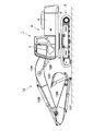
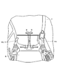
- FIG. 1 is a front view showing a hybrid hydraulic shovel according to an embodiment of the present invention. It is a principal part perspective view which shows the inside of the cab in FIG. It is a block diagram which shows the hydraulic system and electric system which apply to the hybrid hydraulic shovel in FIG. It is a block diagram which shows the hybrid control unit in FIG. It is a block diagram which shows the generator motor request
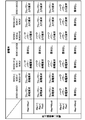
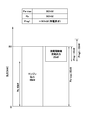
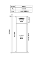
- FIG. 6 is an explanatory view showing a list of output requests based on a storage rate and a current square integration ratio.
- FIG. 13 is a block diagram showing a swing hydraulic power output calculation unit in FIG. 12; It is an explanatory view showing an example of an output of an engine and a generator motor when power running of full power is required. It is explanatory drawing which shows an example of the output of an engine and a generator motor when the power running of half power is requested
- the hybrid hydraulic shovel 1 (hereinafter referred to as the hydraulic shovel 1) includes an engine 21 and a generator motor 27 described later.
- the hydraulic shovel 1 is mounted on a lower traveling unit 2 of a self-propelled crawler type, a pivoting device 3 provided on the lower traveling unit 2, and pivotable via the pivoting device 3 on the lower traveling unit 2.
- the upper revolving superstructure 4 and the working device 12 of the articulated structure which is provided on the front side of the upper revolving superstructure 4 and which performs digging work and the like. At this time, the lower traveling body 2 and the upper revolving superstructure 4 constitute the vehicle body of the hydraulic shovel 1.
- the upper revolving superstructure 4 includes a building cover 6 provided on the revolving frame 5 and accommodating the engine 21 and the like, and a cab 7 on which an operator rides. As shown in FIG. 2, a cab 7 is provided with a driver's seat 8 on which an operator is seated, and around the driver's seat 8, a travel operation device 9 including an operation lever, an operation pedal, etc. And a work operation device 11 including an operation lever and the like. Further, an engine control dial 38 is provided in the cab 7.
- the travel operation device 9 is disposed, for example, on the front side of the driver's seat 8.
- the turning operation device 10 corresponds to, for example, an operation portion in the front-rear direction among operation levers disposed on the left side of the driver's seat 8.
- the work operation device 11 is an operation portion (arm operation) in the left and right direction among the operation levers disposed on the left side of the driver's seat 8 and an operation portion in the front and rear direction among the operation levers disposed on the right side of the driver's seat 8 (Boom operation) and the operation part in the left-right direction (bucket operation) correspond.
- the relationship between the operation direction of the operation lever and the turning operation or the work operation is not limited to that described above, and is appropriately set according to the specifications of the hydraulic shovel 1 or the like.
- the operation devices 9 to 11 are respectively provided with operation amount sensors 9A to 11A for detecting these operation amounts (lever operation amount OA).
- the operation amount sensors 9A to 11A constitute an operation amount detection unit that detects an operation amount for driving a plurality of hydraulic actuators (hydraulic motors 25 and 26, cylinders 12D to 12F).
- the operation amount sensors 9A to 11A detect the operation state of the vehicle body such as, for example, a traveling operation of the lower traveling body 2, a turning operation of the upper swing body 4, a hoisting and raising operation (digging operation) of the work device 12.
- the operation amount sensor 10A detects the swing lever operation amount OAr including the left turn operation amount OAr1 and the right turn operation amount OAr2.
- the operation amount sensor 11A includes a boom lever operation amount OAbm including a boom raising operation amount OAbm1 and a boom lowering operation amount OAbm, an arm lever operation amount OAam including an arm raising operation amount OAam1 and an arm lowering operation amount OAam2, and a bucket cloud operation amount
- the bucket lever operation amount OAbk including the OAbk1 and the bucket dump operation amount OAbk2 is detected.
- the lever operation amount OA includes these operation amounts OAr, OAbm, OAam, OAbk.
- the working device 12 is configured by, for example, a boom 12A, an arm 12B, a bucket 12C, a boom cylinder 12D that drives these, an arm cylinder 12E, and a bucket cylinder 12F.
- the boom 12A, the arm 12B, and the bucket 12C are pin-connected to each other.
- the working device 12 is attached to the pivot frame 5 and is raised and lowered by extending or contracting the cylinders 12D to 12F.
- the hydraulic shovel 1 is mounted with an electric system that controls the generator motor 27 and the like, and a hydraulic system that controls the operation of the work device 12 and the like.
- the system configuration of the hydraulic shovel 1 will be described with reference to FIG.
- the engine 21 is mounted on the swing frame 5.
- the engine 21 is configured by an internal combustion engine such as a diesel engine, for example.
- a hydraulic pump 23 and a generator motor 27 described later are mechanically connected in series and attached to the output side of the engine 21, and the hydraulic pump 23 and the generator motor 27 are driven by the engine 21.
- the operation of the engine 21 is controlled by an engine control unit 22 (hereinafter referred to as the ECU 22).
- the ECU 22 controls the output torque of the engine 21, the rotational speed (engine speed), and the like based on the engine output command Pe from the hybrid control unit 36 (hereinafter referred to as HCU 36).
- the maximum output of the engine 21 is smaller than, for example, the maximum power of the hydraulic pump 23.
- the hydraulic pump 23 is mechanically connected to the engine 21.
- the hydraulic pump 23 can be driven by the torque of the engine 21 alone.
- the hydraulic pump 23 can also be driven by a combined torque (total torque) obtained by adding the assist torque of the generator motor 27 to the torque of the engine 21.
- the hydraulic pump 23 pressurizes the hydraulic oil stored in a tank (not shown), and discharges the hydraulic oil to the traveling hydraulic motor 25, the swing hydraulic motor 26, cylinders 12D to 12F of the working device 12, and the like.
- the hydraulic pump 23 is connected to a traveling hydraulic motor 25 as a hydraulic actuator, a swing hydraulic motor 26, and cylinders 12D to 12F via a control valve 24.
- the hydraulic motors 25, 26 and the cylinders 12D to 12F are driven by pressure oil from the hydraulic pump 23.
- the control valve 24 transfers the pressure oil discharged from the hydraulic pump 23 to the traveling hydraulic motor 25, the revolving hydraulic motor 26, and the cylinders 12 D to 12 F in response to the operation on the traveling operation device 9, the turning operation device 10 and the work operation device 11. Supply or discharge.
- pressure oil is supplied to the traveling hydraulic motor 25 from the hydraulic pump 23 according to the operation of the traveling operation device 9.
- the traveling hydraulic motor 25 drives the lower traveling body 2 to travel.
- Pressure oil is supplied to the swing hydraulic motor 26 from the hydraulic pump 23 in response to the operation of the swing operation device 10.
- the swing hydraulic motor 26 swings the upper swing body 4.
- Pressure oil is supplied to the cylinders 12D to 12F from the hydraulic pump 23 in response to the operation of the work operation device 11.
- the cylinders 12D to 12F lift and lower the working device 12.
- the generator motor 27 (motor generator) is mechanically connected to the engine 21.
- the generator motor 27 is constituted by, for example, a synchronous motor or the like.
- the generator motor 27 functions as a generator using the engine 21 as a power source, generates power for supplying power to the storage device 31 and the swing electric motor 33, and works as a motor using power from the storage device 31 and the swing electric motor 33 as a power source. It plays a dual role of assisting the driving of the engine 21 and the hydraulic pump 23. Therefore, the assist torque of the generator motor 27 is added to the torque of the engine 21 according to the situation, and the hydraulic pump 23 is driven by these torques.
- the pressure oil discharged from the hydraulic pump 23 performs operations of the work device 12, traveling of the vehicle, and the like.
- the generator motor 27 is connected to the pair of DC buses 29A, 29B via a first inverter 28.
- the first inverter 28 is configured using, for example, a plurality of switching elements including a transistor, an insulated gate bipolar transistor (IGBT), and the like.
- the first inverter 28 controls on / off of each switching element by a motor generator control unit 30 (hereinafter referred to as MGCU 30).
- the DC buses 29A and 29B are paired on the positive electrode side and the negative electrode side, and for example, a DC voltage of about several hundred volts is applied.
- the first inverter 28 converts AC power from the generator motor 27 into DC power and supplies the DC power to the storage device 31 and the swing electric motor 33.
- the first inverter 28 converts the DC power of the DC buses 29A and 29B into AC power and supplies the AC power to the generator motor 27.
- the MGCU 30 controls on / off of each switching element of the first inverter 28 based on the generator motor output command Pmg from the HCU 36 and the like.
- the MGCU 30 controls the generated power at the time of power generation of the generator motor 27 and the driving power at the time of powering.
- Power storage device 31 is electrically connected to generator motor 27.
- the storage device 31 is constituted by a plurality of cells (not shown) made of, for example, lithium ion batteries, and is connected to the DC buses 29A and 29B.
- the storage device 31 charges the power supplied from the generator motor 27 when the generator motor 27 generates electric power, and supplies the drive power toward the generator motor 27 when the generator motor 27 is in power operation (assist drive).
- the power storage device 31 charges regenerative electric power supplied from the swing electric motor 33 at the time of regeneration of the swing electric motor 33 and supplies drive power toward the swing electric motor 33 at the time of power running of the swing electric motor 33.
- power storage device 31 absorbs the regenerative electric power generated by turning electric motor 33 at the time of turning braking of hydraulic shovel 1, and DC power lines 29A, 29B. Keep the voltage constant.
- Power storage device 31 is controlled by battery control unit 32 (hereinafter referred to as BCU 32).
- the BCU 32 constitutes a power storage device state detection unit.
- the BCU 32 detects the state of charge SOC as a first index representing the state of the power storage device 31, and detects the current square integration ratio Risc as a second index representing the state of the power storage device 31.
- the storage ratio SOC is a value corresponding to the storage amount of the storage device 31.
- the current square integration ratio Risc is a value corresponding to the current square integration value of the power storage device 31.
- the BCU 32 outputs the storage ratio SOC, the current square integration ratio Risc, and the like to the HCU 36.
- power storage device 31 has, for example, a voltage of 350 V, a discharge capacity of 5 Ah, an appropriate use range of storage ratio SOC of, for example, 30% to 70%, and an appropriate use cell temperature of ⁇ 20 ° C. to 60 A lithium ion battery set to not more than ° C. is used.
- the appropriate use range and the like of the state of charge SOC are not limited to the values described above, and are appropriately set in accordance with the specifications and the like of the power storage device 31.
- the maximum output of the engine 21 is smaller than the maximum pump absorption power.
- the ratio of contribution of the engine assist by the power running of the generator motor 27 at the time of the vehicle body operation is larger than when the engine 21 has a sufficiently large output with respect to the maximum pump absorption power. Therefore, power storage device 31 repeatedly repeats charging and discharging.
- the deterioration rate of the power storage device 31 differs depending on the state of charge SOC at the time of charging or discharging, and the strength of the charging or discharging itself. For example, for a power storage device 31 such as a lithium ion battery, an appropriate use range for the storage rate and cell temperature is determined by the manufacturer (for example, 30% to 70% in storage rate, -20 ° C. or more at cell temperature) 60 ° C or less). If the power storage device 31 is used beyond this range, the deterioration rate is greatly increased.
- the appropriate use range of the power storage device 31 is determined in advance also for the strength of charge and discharge. It is general to use a current squared integrated value as an indicator of charge and discharge intensity. This is an index that represents how much current has been input or output in a past fixed time T going back from the current time by T-time integration of the square of the current. At this time, a plurality of times T are often set. This index is appropriately set in accordance with the specifications and the like of power storage device 31. Therefore, if the power storage device 31 is used beyond the upper limit value of the current square integrated value, deterioration of the power storage device 31 is promoted. Therefore, power storage device 31 is used so as not to exceed the upper limit value of the current square integrated value as much as possible.
- the BCU 32 includes, for example, a current sensor (not shown) that detects the current of charging or discharging of the power storage device 31, and calculates the current square integration ratio Risc based on the detected current.
- the current square integration ratio Risc is not limited to the calculation by the BCU 32, but may be calculated by the HCU 36 based on the detected value of the current detected by the BCU 32 during charging and discharging, for example.
- the swing electric motor 33 (swing motor) is driven by the power from the generator motor 27 or the storage device 31.
- the swing electric motor 33 is formed of, for example, a three-phase induction motor, and is provided on the swing frame 5 together with the swing hydraulic motor 26.
- the swing electric motor 33 cooperates with the swing hydraulic motor 26 to drive the swing device 3. For this reason, the turning device 3 is driven by the combined torque of the turning hydraulic motor 26 and the turning electric motor 33 to turn and drive the upper turning body 4.
- the swing electric motor 33 is connected to the DC buses 29A and 29B via the second inverter 34.
- the swing electric motor 33 has two roles of power running to rotate by receiving electric power from the power storage device 31 and the generator motor 27, and regeneration to generate power with extra torque at the time of swing braking and charge the power storage device 31. Play. Therefore, electric power from the generator motor 27 or the like is supplied to the swing electric motor 33 at the time of powering via the DC buses 29A, 29B. Thereby, the swing electric motor 33 generates rotational torque according to the operation of the swing operation device 10 to assist the drive of the swing hydraulic motor 26, and drives the swing device 3 to swing the upper swing body 4 Let
- the second inverter 34 is configured using a plurality of switching elements. The turning on / off of each switching element of the second inverter 34 is controlled by a swing electric motor control unit 35 (hereinafter referred to as the RMCU 35).
- the RMCU 35 swing electric motor control unit 35
- the second inverter 34 converts DC power of the DC buses 29A and 29B into AC power and supplies the AC power to the swing electric motor 33.
- second inverter 34 converts AC power from swing electric motor 33 into DC power and supplies the DC power to storage device 31 and the like.
- the RMCU 35 controls on / off of each switching element of the second inverter 34 based on the swing electric motor output command Per from the HCU 36 and the like. Thereby, the RMCU 35 controls the regenerative power at the time of regeneration of the swing electric motor 33 and the drive power at the time of power running. Further, the RMCU 35 detects regenerative power and drive power of the swing electric motor 33, and outputs these to the HCU 36 as a swing electric motor output P0er.
- the swing electric motor output P0er is not limited to one detected by the RMCU 35, but may be estimated (calculated) by the HCU 36 based on, for example, the current swing electric motor output command Per. Furthermore, the RMCU 35 detects the turning speed Vr based on the rotational speed of the turning electric motor 33, and outputs the turning speed Vr to the HCU 36.
- the HCU 36 configures a controller together with, for example, the MGCU 30, the RMCU 35, and the like, and controls the output of the power storage device 31.
- the HCU 36 is configured by, for example, a microcomputer, and is electrically connected to the ECU 22, the MGCU 30, the RMCU 35, and the BCU 32 using a CAN 37 (Controller Area Network) or the like.
- the HCU 36 controls the engine 21, the generator motor 27, the swing motor 33, and the power storage device 31 while communicating with the ECU 22, the MGCU 30, the RMCU 35, and the BCU 32.
- the HCU 36 receives the storage ratio SOC, the current square integration ratio Risc, the turning electric motor output P0er, and other vehicle information VI through the CAN 37 or the like.
- the operation amount sensors 9A to 11A are connected to the HCU 36. Accordingly, the lever operation amount OA including various operation amounts OAr, OAbm, OAam, OAbk is input to the HCU 36.
- an engine control dial 38 is connected to the HCU 36, and the target rotation speed ⁇ e of the engine 21 set by the engine control dial 38 is input.
- the HCU 36 controls the output of the power storage device 31 based on the state of charge SOC as a first index and the current square integration ratio Risc as a second index.
- the HCU 36 has a target value SOC0 that is a reference value determined for the state of charge SOC, and a use lower limit value SOC1 and a use upper limit value SOC2 that are limit values.
- the use lower limit value SOC1 is the lower limit value of the appropriate use range of the state of charge SOC.
- the use upper limit value SOC2 is the upper limit value of the appropriate use range of the state of charge SOC.
- the target value SOC0 of the storage ratio SOC is 50%
- the use lower limit value SOC1 is 30%
- the use upper limit value SOC2 is 70%.
- the HCU 36 has an intermediate value Risc0 which is a reference value set in the current square integration ratio Risc, and an upper limit value Risc2 which is a limit value.
- a lower limit value Risc1 is also set to the current square integration ratio Risc.
- the middle value Risc0 of the current square integration ratio Risc is 70%
- the lower limit Risc1 is 0%
- the upper limit Risc2 is 100%.
- the allowable range of the state of charge SOC is equal to or more than a value reduced by the lower margin X1 from the target value SOC0 and equal to or smaller than a value increased by the upper margin X2 from the target value SOC0. That is, it is the range shown in the following equation (1).
- the lower margin X1 is 15%
- the upper margin X2 is also 15%.
- the lower margin X1 and the upper margin X2 do not have to be the same value, and may be different values.
- the allowable range of the current square integration ratio Risc is a range equal to or less than the intermediate value Risc0. That is, it is a range shown in the following equation (2).
- the engine control dial 38 is configured of a rotatable dial, and sets a target rotational speed ⁇ e of the engine 21 according to the rotational position of the dial.
- the engine control dial 38 is located in the cab 7, is rotated by the operator, and outputs a command signal corresponding to the target rotational speed ⁇ e.
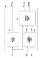
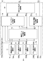
- the HCU 36 includes a generator motor request output computing unit 40, a maximum output computing unit 50, and an output command computing unit 60.
- maximum output calculating unit 50 and output command calculating unit 60 do not exceed the lower limit SOC1 or upper limit SOC2 of the storage ratio SOC based on the output request from the generator motor request output calculating unit 40
- the output control unit is configured to control the output of the power storage device 31 so that the current square integration ratio Risc does not exceed the upper limit value Risc2.
- the generator motor request output calculation unit 40 constitutes an output request unit. Therefore, the generator motor request output calculation unit 40 prevents the storage ratio SOC and the current square integration ratio Risc from deviating from the allowable range when the storage ratio SOC and the current square integration ratio Risc are within the allowable range. Request the output of In addition, when the storage ratio SOC exceeds the allowable range and deviates from the target value SOC0 (SOC ⁇ SOC0-X1 or SOC> SOC0-X2), the generator motor required output calculation unit 40 sets the current square integration ratio Risc to an intermediate value. The output of the power storage device 31 is requested so that the state of charge SOC approaches the target value SOC0 while allowing deviation from Risc0.
- the generator motor request output calculation unit 40 allows the storage ratio SOC to deviate from the target value SOC0 when the current square integration ratio Risc deviates from the intermediate value Risc0 beyond the allowable range (Risc> Risc0). The output of the storage device 31 is requested so that the current square integration ratio Risc approaches the intermediate value Risc0.
- the generator motor request output calculation unit 40 determines the generator motor request output Pmg1 in order to operate the generator motor 27 appropriately (powering operation or power generation operation) according to the state of the power storage device 31.
- the generator motor request output calculation unit 40 requests the generator motor 27 to generate power when the state of charge SOC falls below the target value SOC0 (SOC ⁇ SOC0) and the current square integration ratio Risc is within the allowable range.
- a powering request unit 40B that requests the generator motor 27 to perform powering when the storage ratio SOC exceeds the target value SOC0 (SOC> SOC0) and the current square integration ratio Risc is within the allowable range.
- the generator motor request output calculation unit 40 further includes an output reduction request unit 43B that requests the generator motor 27 to generate power or power running by reducing the output as the current square integration ratio Risc approaches the upper limit value Risc2. There is.
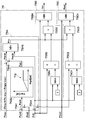
- the generator motor request output calculation unit 40 includes a storage ratio deviation calculation unit 41, a storage ratio request output calculation unit 42, a current square integration ratio request output calculation unit 43, and a saturation calculation unit 44.
- An adder 45 is provided.
- the power generation ratio SOC, the current square integration ratio Risc, and the turning electric motor output P0er are input to the generator motor request output calculation unit 40.
- the storage ratio request output calculation unit 42 outputs a storage ratio request output Psoc1 as an output requested to the generator motor 27 according to the storage ratio SOC.
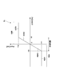
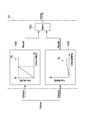
- the storage ratio request output calculation unit 42 has, for example, a table T1 as shown in FIG. 6 in order to calculate the storage ratio request output Psoc1 based on the storage ratio deviation ⁇ SOC.
- the table T1 requests the storage ratio according to the magnitude of the absolute value of the storage ratio deviation ⁇ SOC.
- the output Psoc1 is set to a value (negative value) increased to the power generation side. At this time, it is preferable that the state of charge SOC be lower than the target value SOC0, and the power generation operation of the generator motor 27 approach the target value SOC0.
- the table T1 displays the storage ratio request output Psoc1 according to the magnitude of the absolute value of the storage ratio deviation ⁇ SOC. Is set to the value (positive value) increased to the power running side. At this time, it is preferable that the state of charge SOC is higher than the target value SOC0, and the power running operation of the generator motor 27 brings the value closer to the target value SOC0.
- the storage ratio request output calculation unit 42 outputs the storage ratio request output Psoc1 that has become the power generation request. Therefore, the part of the table T1 corresponding to the negative storage ratio deviation ⁇ SOC constitutes the power generation output request unit 42A. Further, the power generation output request unit 42A makes the power generation ratio request unit 42A1, which makes a power generation request with the power storage ratio request output Psoc1 with the maximum value Y11 when the storage ratio SOC is out of the allowable range, and the storage ratio SOC is within the allowable range. There is a power generation output reduction request unit 42A2 that makes a power generation request by lowering the required power storage ratio output Psoc1 compared to when the power storage ratio SOC is out of the allowable range.
- the storage ratio request output calculation unit 42 outputs the storage ratio request output Psoc1 that has become the powering request. Therefore, a portion of the table T1 corresponding to the positive storage ratio deviation ⁇ SOC constitutes a powering output request unit 42B. Further, the powering output request unit 42B performs the powering request with the power ratio request output Psoc1 of the maximum value Y12 when the power ratio SOC is out of the allowable range, and the power ratio SOC is within the allowable range. In some cases, there is a powering output reduction request unit 42B2 that makes a powering request by reducing the required power storage ratio output Psoc1 compared to when the storage ratio SOC is out of the allowable range.
- the storage ratio request output calculation unit 42 generates the storage ratio request output Psoc1 on the power generation side in proportion to the absolute value of the storage ratio deviation ⁇ SOC.
- the storage ratio request output calculation unit 42 moves the storage ratio request output Psoc1 to the power running side in proportion to the magnitude of the absolute value of the storage ratio deviation ⁇ SOC. It should be increased.
- the present invention is not limited to this, and when the storage ratio deviation ⁇ SOC is between the lower margin X1 and the upper margin X2, the storage ratio request output calculation unit 42 stores the electric storage with respect to the absolute value of the storage ratio deviation ⁇ SOC.
- the magnitude of the rate request output Psoc1 may be monotonously increased. For this reason, not only the proportional characteristic but various characteristics can be adopted for the storage ratio request output calculation unit 42.
- the current square integration ratio request output calculation unit 43 outputs the current square integration ratio request output Prisc1 as an output requested to the generator motor 27 according to the current square integration ratio Risc.
- the current square integration ratio request output calculation unit 43 has, for example, a table T2 as shown in FIG. 7 in order to calculate the current square integration ratio request output Prisc1 based on the current square integration ratio Risc.
- the table T2 shows the current square as the current square integration ratio Risc approaches the upper limit Risc2.
- the integration ratio request output Prisc1 is set to a value reduced from the maximum value Y22.
- the current square integration ratio request output calculation unit 43 requests the power generation or the power running with the current square integration ratio request output Prisc1 of the maximum value Y22 when the current square integration ratio Risc is within the allowable range. And, when the current square integration ratio Risc is out of the allowable range, the power reduction request output Psoc1 is required to reduce power storage ratio output compared with when the current square integration ratio Risc is within the allowable range to request power generation or power running And 43B.
- the current square integration ratio request output calculation unit 43 outputs the current square integration ratio request output in proportion to the magnitude of the current square integration ratio Risc between the intermediate value Risc0 and the upper limit value Risc2. It is intended to reduce Prisc1.
- the present invention is not limited thereto, and the current square integration ratio request output calculation unit 43 calculates the current relative to the magnitude of the current square integration ratio Risc when the current square integration ratio Risc is between the intermediate value Risc0 and the upper limit Risc2.
- the magnitude of the square integration ratio request output Prisc1 may be monotonically decreased. Therefore, the current square integration ratio request output calculation unit 43 can adopt various characteristics as well as the proportional characteristic.
- Saturation operation unit 44 calculates storage device request output Pmg10 based on the state of power storage device 31 based on storage ratio request output Psoc1 and current square integration ratio request output Prisc1. Specifically, in addition to the storage ratio request output Psoc1 and the current square integration ratio request output Prisc1, the saturation operation unit 44 inverts the sign of the current square integration ratio request output Prisc1 by the inverting input unit 44A ( -Prisc 1) is input. At this time, the current square integration ratio request output Prisc1 is all positive. The current square integration ratio request output Prisc1 indicates an upper limit value that is a limit value on the power running side. The negative value (-Prisco) of the current square integration ratio request output Prisc1 indicates a lower limit value which is a limit value on the power generation side.
- the saturation calculation unit 44 when there is a storage ratio request output Psoc1 in the range from the upper limit value Prisc1 to the lower limit value (-Prisco1) (-Prisco1 ⁇ Psoc1 ⁇ Prisco1), the saturation calculation unit 44 has the same value as the storage ratio request output Psoc1.
- the saturation calculating unit 44 outputs the storage device request output Pmg10 having the same value as the lower limit value (-Prisco1).
- the generator motor request output calculation unit 40 compares the magnitude of the storage ratio SOC with deviation from the target value SOC0 and the magnitude of the current square integration ratio Risc with deviation from the intermediate value Risc0 toward the upper limit Risc2.
- a storage device request output Pmg10 shown in 8 is output.
- the power generation request unit 40A is configured of a power generation output request unit 42A, a maximum output request unit 43A, and a saturation calculation unit 44.
- the powering request unit 40B is configured of a powering output request unit 42B, a maximum output request unit 43A, and a saturation calculation unit 44.
- power generation request unit 40A lowers power generation output to perform power generation request by lowering power storage ratio request output Psoc1 compared to when power storage ratio SOC is outside the allowable range. It has a request unit 42A2.
- the powering request unit 40B lowers the storage ratio request output Psoc1 compared to when the storage ratio SOC is out of the allowable range to request the powering output reduction request unit 42B2 have.
- the storage ratio request output calculation unit 42, the current square integration ratio request output calculation unit 43, the saturation calculation unit 44, and the like execute the above-described calculation processing.
- the contents of these arithmetic processes will be specifically described with reference to FIG.
- Arithmetic unit 44 sets power storage device request output Pmg 10 as the maximum power generation output according to the specifications of generator motor 27. At this time, the saturation operation unit 44 requests power generation at full power.
- saturation operation unit 44 sets storage device request output Pmg10 to the minimum value (0 kW). At this time, the saturation calculation unit 44 stops the request for power generation and power running.
- the intermediate value Risc0 does not necessarily have to be 50%.
- the vehicle is charged in a non-operational state until the state of charge SOC reaches the target value SOC0.
- the intermediate value Risc0 is 70%.
- the saturation operation unit 44 sets the power storage device required output Pmg 10 as the maximum power running output on the specifications of the generator motor 27. At this time, the saturation operation unit 44 requests power running at full power.
- the saturation calculation unit 44 reduces the power storage device request output Pmg10 from the maximum power running output. At this time, the saturation operation unit 44 requests powering with half power.
- saturation operation unit 44 sets storage device request output Pmg10 to the minimum value (0 kW). At this time, the saturation calculation unit 44 stops the request for power generation and power running.
- the intermediate value Risc0 does not necessarily have to be 50%.
- the current square integration ratio Risc is the intermediate value Risc0 and the state of charge SOC is the upper limit SOC2
- the vehicle body discharges in a non-operational state until the state of charge SOC reaches the target value SOC0.
- the intermediate value Risc0 is set to 70%.
- saturation operation unit 44 sets storage device request output Pmg10 to a sufficiently small discharge power or charge power so that storage ratio SOC converges to target value SOC0.
- a storage device request output Pmg10 based on the state of the storage device 31 and a value (-P0er) obtained by inverting the sign of the swing electric motor output P0er are input to the adder 45 by the inverting input unit 45A.
- the adder 45 adds the value obtained by multiplying the swing electric motor output P0er by -1 to the power storage device request output Pmg10 to calculate this addition value.
- the power generation request and the powering request are preferentially executed according to the swing electric motor output P0er.
- the adder 45 performs processing taking this point into consideration.
- the storage device request output Pmg10 is a powering request and the swing electric motor 33 is in a power running state
- the value corresponding to the swing electric motor output P0er is decreased from the storage device request output Pmg10 which is discharge power.
- the storage device request output Pmg10 is a power generation request and the swing electric motor 33 is in a power generation state
- a value corresponding to the swing electric motor output P0er is reduced from the storage device request output Pmg10 which is generated power.
- the adder 45 sets the generator motor request output Pmg1 to the addition value. However, when the addition value on the power running side exceeds the maximum power running output, the adder 45 sets the generator motor request output Pmg1 to the maximum power running output. The adder 45 sets the generator motor required output Pmg1 to the maximum power generation output when the addition value on the power generation side exceeds the maximum power generation output. The adder 45 outputs a final required generator motor output Pmg1 in consideration of the swing electric motor output P0er.
- the maximum output calculation unit 50 constitutes a part of the output control unit.
- the maximum output calculation unit 50 prohibits the powering of the generator motor 27 when the storage ratio SOC reaches the lower limit value of use SOC1.
- a storage ratio generation limit gain calculation unit 52B is provided as a power generation prohibition unit that prohibits the power generation of the generator motor 27 when the value SOC2 is reached.
- the maximum output calculation unit 50 prohibits both the power running and the power generation of the generator motor 27. It has an operation unit 52C.
- the maximum output calculation unit 50 includes an engine maximum output calculation unit 51, a generator motor output limit gain calculation unit 52, and a generator motor maximum output calculation unit 53.
- the target engine speed ⁇ e, the storage ratio SOC, and the current square integration ratio Risc are input to the maximum output calculation unit 50.
- the engine maximum output calculation unit 51 has a table (not shown) indicating the correspondence between the engine target speed ⁇ e and the engine maximum output Pe-max. At this time, the engine maximum output Pe-max indicates the maximum output that can be supplied from the engine 21 when the engine 21 is driven at the engine target speed ⁇ e. The engine maximum output calculation unit 51 calculates the engine maximum output Pe-max based on the target engine speed ⁇ e, and outputs the calculated engine maximum output Pe-max.
- the generator motor output limiting gain computing unit 52 includes a storage ratio power running limiting gain computing unit 52A, a storage ratio power limiting gain computing unit 52B, a current square integration ratio output limiting gain computing unit 52C, and a minimum. And value selectors 52D and 52E.
- the storage ratio SOC and the current square integration ratio Risc are input to the generator motor output limit gain calculation unit 52.
- the storage ratio power running limit gain calculation unit 52A includes a table T3 to calculate the storage ratio power running limit gain Kmgm0 based on the storage ratio SOC. At this time, the storage ratio power running limit gain Kmgm0 limits the power running output of the generator motor 27 in order to suppress the storage ratio SOC from decreasing to the lower limit value a1 by the powering of the generator motor 27.
- the power storage ratio power running limit gain calculation unit 52A calculates a storage ratio power execution limit gain Kmgm0 according to the storage ratio SOC using the table T3.
- the lower limit value a1 is the same value as the use lower limit value SOC1.
- the table T3 sets the storage ratio power running limit gain Kmgm0 to a value between the minimum value and the maximum value according to the degree of decrease from the appropriate reference value a2.
- the appropriate reference value a2 is set to a large value with a predetermined margin from the lower limit value a1. For example, when the lower limit value a1 is 30%, the appropriate reference value a2 is set to a value of about 35%.
- the appropriate reference value a2 becomes the same value as the lower limit value of the tolerance
- the storage ratio generation limit gain calculation unit 52B has a table T4 to calculate the storage ratio generation limit gain Kmgg0 based on the storage ratio SOC. At this time, the storage ratio power generation limiting gain Kmgg0 limits the power generation output of the generator motor 27 in order to suppress the storage ratio SOC from rising to the upper limit value a4 due to the power generation of the generator motor 27.
- the power storage ratio generation limit gain calculation unit 52B calculates a storage ratio power generation limit gain Kmgg0 according to the storage ratio SOC using the table T4.
- the upper limit value a4 is the same value as the use upper limit value SOC2.
- the table T4 decreases the storage ratio power running limit gain Kmgm0 as the storage ratio SOC increases.
- the table T4 sets the storage ratio power generation limiting gain Kmgg0 to a value between the minimum value and the maximum value according to the degree of increase from the appropriate reference value a3.
- the appropriate reference value a3 is set to a small value with a margin determined in advance from the upper limit value a4. For example, when the upper limit value a4 is 70%, the appropriate reference value a3 is set to about 65%.
- the appropriate reference value a3 becomes the same value as the upper limit value of the tolerance
- the current square integration ratio output limiting gain calculation unit 52C has a table T5 to calculate the current square integration ratio output limiting gain Krisco based on the current square integration ratio Risc. At this time, the current square integration ratio output limiting gain Krisc0 is used to control the power generation output and the power running output of the generator motor 27 in order to suppress the current square integration ratio Risc from rising to the upper limit b2 due to the power running and generation of the generator motor 27. It is a limitation.
- the current square integration ratio output limiting gain calculation unit 52C calculates a current square integration ratio output limiting gain Krisco according to the current square integration ratio Risc using the table T5.
- the table T5 decreases the current square integration ratio output limiting gain Krisc0 as the current square integration ratio Risc rises.
- the table T5 sets the current square integration ratio output limiting gain Krisco between the minimum value and the maximum value according to the degree of increase from the appropriate reference value b1.
- the appropriate reference value b1 is set to a small value with a predetermined margin from the upper limit value b2.
- the appropriate reference value b1 is set to a value of about 95%.
- the upper limit b2 is the same value as the limit value (upper limit Risc2) of the current square integration ratio Risc.
- the appropriate reference value b1 is a value different from the upper limit value (intermediate value Risc0) of the allowable range of the current square integration ratio Risc is illustrated, these may be the same value as each other.
- the minimum value selection unit 52D compares the storage ratio power running limit gain Kmgm0 by the storage rate power running limit gain calculation unit 52A with the current square integration ratio output limit gain restriction gain Krsc0 by the current square integration ratio output limit gain calculation unit 52C.
- the minimum value selection unit 52D selects the minimum value among the storage ratio power running limit gain Kmgm0 and the current square integration ratio output limit gain Krisc0, and outputs it as the generator motor power running limit gain Kmgm.
- the minimum value selection unit 52E compares the storage ratio generation limit gain Kmgg0 by the storage ratio generation limit gain calculation unit 52B with the current square integration ratio output limit gain restriction gain Krsc0 by the current square integration ratio output limit gain calculation unit 52C.
- the minimum value selection unit 52E selects the minimum value among the storage ratio power generation limiting gain Kmgg0 and the current square integration ratio output limiting gain Krisc0, and outputs it as the generator motor power generation limiting gain Kmgg.
- the generator motor maximum output calculation unit 53 has a table (not shown) of the maximum powering output of the generator motor 27 and the maximum power generation output with respect to the engine target rotation speed ⁇ e, similarly to the engine maximum output calculation unit 51.
- the generator motor maximum output calculation unit 53 calculates the power running maximum output and the power generation maximum output of the generator motor 27 based on the target rotation speed ⁇ e of the engine 21.
- the generator motor maximum output calculation unit 53 outputs a value obtained by acting (multiplying) the power running maximum output determined from the target rotation speed ⁇ e with the generator motor power running restriction gain Kmgm as a generator motor maximum power run output Pmgm-max.
- the generator motor maximum output calculation unit 53 outputs a value obtained by acting (multiplying) the generator motor power generation limiting gain Kmgg on the power generation maximum output determined from the target rotational speed ⁇ e as the generator motor maximum power generation output Pmgg-max.
- the output command calculation unit 60 includes a pump estimation input calculation unit 61, a generator motor power running generation request determination unit 62, a generator motor power running output calculation unit 63, and a generator motor generation output calculation unit 64.
- a generator motor output command calculation unit 65 and an engine output command calculation unit 66 are provided.
- the output command calculation unit 60 includes a turning speed Vr, lever operation amounts OA (OAr, OAbm, OAam, OAbk), other vehicle information VI, a storage ratio SOC, a current square integration ratio Risc, a generator motor A required output Pmg1, an engine maximum output Pe-max, a generator motor maximum power running output Pmgm-max, and a generator motor maximum power generation output Pmgg-max are input.
- the pump estimation input calculation unit 61 calculates a pump estimation input Pp necessary for operating the vehicle body according to each lever operation amount OA and a swing electric motor output command Per.
- the pump estimation input calculation unit 61 calculates the pump estimation input Pp and the turning electric motor output command Per, the turning speed Vr, other vehicle information VI, the storage ratio SOC, the current square integration ratio Risc, the engine Consider the maximum output Pe-max and the generator motor maximum powering output Pmgm-max.
- the pump estimation input calculation unit 61 includes the turning speed Vr, other vehicle information VI, the storage ratio SOC, the current square integration ratio Risc, the engine maximum output Pe-max, and the generator motor maximum powering output Pmgm max and each lever operation amount OA are input.
- the other vehicle information VI will be omitted and described.
- the specific configuration of the pump estimation input calculation unit 61 will be described later.
- a generator motor request output Pmg1 is input to the generator motor powering generation request determination unit 62.
- the generator motor powering power generation request determination unit 62 outputs the generator motor powering request output Pmgm1 and the generator motor power generation request output Pmgg1.
- the generator motor power running output calculation unit 63 has a subtractor 63A, a maximum value selection unit 63B, and a minimum value selection unit 63C.
- the generator motor powering output calculating unit 63 receives the pump estimation input Pp, the maximum engine power Pe-max, the generator motor maximum powering output Pmgm-max, and the generator motor powering request output Pmgm1.
- the subtractor 63A subtracts the engine maximum output Pe-max from the pump estimation input Pp, and outputs this subtraction value.
- the maximum value selection unit 63B compares the output from the subtractor 63A, 0, and the generator motor powering request output Pmgm1.
- the maximum value selection unit 63B selects the maximum value among the output from the subtractor 63A, 0, and the generator motor powering request output Pmgm1 and outputs it as the generator motor powering output Pmgm10. At this time, the generator motor power running output Pmgm10 becomes 0 or a positive value (Pmgm10 ⁇ 0).
- the minimum value selection unit 63C compares the generator-motor powering output Pmgm10 with the generator-motor maximum powering output Pmgm-max. The minimum value selecting unit 63C selects the minimum value among the generator motor power running output Pmgm10 and the generator motor maximum power output Pmgm-max, and outputs the selected value as the generator motor power output command Pmgm.
- the generator motor power running output calculation unit 63 compares the estimated pump input Pp with the maximum engine output Pe-max. When the estimated motor input Pp is larger than the maximum engine output Pe-max (Pp> Pe-max), the generator motor power running output calculator 63 generates an electric motor that generates a difference between the estimated pump input Pp and the maximum engine output Pe-max. Power running output command Pmgm. However, the generator motor powering output command Pmgm is adjusted so as not to be larger than the generator motor maximum powering output Pmgm-max.
- the generator motor power running output calculation unit 63 secures a portion lacking in the output of the engine 21 with respect to the hydraulic load by the power running output of the generator motor 27. Then, the generator motor powering output calculating unit 63 controls the powering operation of the generator motor 27 so as to satisfy the generator motor powering request output Pmgm1.
- the generator motor generator output calculation unit 64 includes a subtractor 64A, maximum value selection units 64B, 64D, 64E, and a generated power conversion unit 64C.
- the generator motor generator output calculation unit 64 receives the pump estimation input Pp, the maximum engine output Pe-max, the generator motor maximum generator output Pmgg-max, and the generator motor generator request output Pmgg1.
- the subtractor 64A subtracts the pump estimation input Pp from the engine maximum output Pe-max, and outputs this subtraction value.
- Maximum value selection unit 64B compares the output from subtractor 64A with zero. Maximum value selection unit 64B selects the maximum value between the output from subtractor 64A and 0. At this time, the maximum value selection unit 64B outputs 0 or a positive value. The output from the maximum value selection unit 64B is multiplied by -1 by the generated power conversion unit 64C and converted into a negative value. As a result, the generated power conversion unit 64C outputs the first generator motor generated output Pmgg10 that is sized according to the difference between the engine maximum output Pe-max and the pump estimated input Pp. At this time, the first generator motor power output Pmgg10 becomes 0 or a negative value (Pmgg10 ⁇ 0).
- the maximum value selection unit 64D compares the generator motor generation request output Pmgg1 with the generator motor maximum generator output Pmgg-max. The maximum value selection unit 64D selects the larger one of the generator motor generation request output Pmgg1 and the generator motor maximum generator output Pmgg-max. Here, the generator-motor generation request output Pmgg1 and the generator-motor maximum generation output Pmgg-max are both negative values. Accordingly, the maximum value selection unit 64D selects one of the values closer to 0 (the smaller absolute value) of the generator motor generation request output Pmgg1 and the generator motor maximum generator output Pmgg-max. The maximum value selection unit 64D outputs, as the second generator motor power output Pmgg20, a selected one of the generator motor power requirement output Pmgg1 and the generator motor maximum power output Pmgg-max.
- the maximum value selection unit 64E compares the first generator motor power output Pmgg10 with the second generator motor power output Pmgg20. The maximum value selecting unit 64E selects the larger one of the first generator motor power output Pmgg10 and the second generator motor power output Pmgg20. Here, the first generator motor power output Pmgg10 and the second generator motor power output Pmgg20 both have negative values. Therefore, the maximum value selection unit 64E selects one of the first generator motor power output Pmgg10 and the second generator motor power output Pmgg20 that is close to 0 (smaller in absolute value). Maximum value selection unit 64E outputs a selected one of first generator motor power output Pmgg10 and second generator motor power output Pmgg 20 as generator motor power output command Pmgg.
- the generator motor generated output calculation unit 64 compares the estimated pump input Pp with the maximum engine output Pe-max.
- the generator-motor generation output calculation unit 64 outputs a generator motor generation output command Pmgg which has become zero.
- the generator motor generator output command Pmgg is set to 0, and the generator motor 27 does not perform the power generation operation.
- the generator motor powering request output Pmgm1 is selected to have a minimum absolute value, and is set as a generator motor powering output command Pmgm.
- the generator motor generator output calculator 64 controls the generator operation of the generator motor 27 so as to satisfy the generator motor powering request output Pmgm1 as much as possible while responding to the hydraulic load.
- the generator motor output command calculation unit 65 adds the generator motor powering output command Pmgm and the generator motor power output command Pmgg.
- the generator motor output command computation unit 65 outputs this added value as a generator motor output command Pmg.
- the engine output command calculation unit 66 subtracts the generator motor output command Pmg from the pump estimation input Pp. Engine output command calculation unit 66 outputs this subtraction value as engine output command Pe.
- the output command calculation unit 60 constitutes a part of the output control unit.
- the output command calculation unit 60 controls the output of the storage device 31 based on the lever operation amount OA detected by the operation amount sensors 9A to 11A in addition to the request for the output from the generator motor request output calculation unit 40. Further, a pump estimation input calculation unit 61 of the output command calculation unit 60 calculates a pump estimation input Pp according to each lever operation amount OA. At this time, the generator motor power running output computing unit 63 of the output command computing unit 60 outputs a generator motor power running output command Pmgm in which priority is given to securing the pump estimation input Pp.
- the generator motor generation output calculation unit 64 of the output command calculation unit 60 outputs a generator motor generation output command Pmgg in which priority is given to securing of the pump estimation input Pp. For this reason, it is possible to suppress the decrease in the vehicle speed and to reduce the chance of giving the operator an operation stress or a sense of discomfort.
- the pump estimation input calculation unit 61 includes a swing basic output calculation unit 71, a boom basic output calculation unit 72, an arm basic output calculation unit 73, a bucket basic output calculation unit 74, and a swing boom output.
- a distribution operation unit 75, an arm bucket output distribution operation unit 76, a swing hydraulic motor output distribution operation unit 77, and a total pump output operation unit 78 are provided.
- the turning basic output calculation unit 71 calculates a turning basic output Pr0 that monotonously increases with respect to the turning lever operation amount OAr. As shown in FIG. 15, the turning basic output calculating unit 71 includes a maximum value selecting unit 71A, an initial turning basic output calculating unit 71B, an output reduction gain calculating unit 71C, a gain converting unit 71D, and a multiplier 71E. Have.
- the maximum value selection unit 71A compares the left turning operation amount OAr1 and the right turning operation amount OAr2 included in the turning lever operation amount OAr. The maximum value selection unit 71A selects the largest value among the left turning operation amount OAr1 and the right turning operation amount OAr2 and outputs the selected value as the turning operation amount OAr3.
- the initial turning basic output calculation unit 71B has a table T6 to calculate the initial turning basic output Pr10 based on the turning operation amount OAr3.
- the initial turning basic output calculation unit 71B calculates an initial turning basic output Pr10 according to the turning operation amount OAr3 using the table T6.
- the initial turning basic output Pr10 corresponds to an output necessary to perform the turning operation according to the turning operation amount OAr3.
- the initial turning basic output Pr10 becomes a large value as the turning operation amount OAr3 increases.
- the initial turning basic output Pr10 becomes a maximum value and is saturated.
- the output reduction gain calculation unit 71C has a table T7 to calculate the output reduction gain Kr based on the turning speed Vr.
- the output reduction gain calculation unit 71C calculates the output reduction gain Kr according to the turning speed Vr using the table T7.
- the power reduction gain Kr has a small value to reduce the turning output as the turning speed Vr increases.
- the output reduction gain Kr becomes a minimum value and is saturated.
- the output reduction gain Kr (%) output from the output reduction gain calculation unit 71C is represented by a percentage. For this reason, the output reduction gain Kr is converted by the gain conversion unit 71D into a ratio with 1 as the maximum value. That is, the gain conversion unit 71D outputs a value obtained by dividing the output reduction gain Kr by 100 as the converted output reduction gain Kr10.
- the multiplier 71E calculates the product of the initial turning basic output Pr10 and the output reduction gain Kr10, and outputs a turning basic output Pr0.
- the boom basic output calculation unit 72 calculates a boom basic output Pbm0 that monotonously increases with respect to the boom lever operation amount OAbm. As shown in FIG. 16, the boom basic output calculating unit 72 includes a boom raising basic output calculating unit 72A, a boom lowering basic output calculating unit 72B, and a maximum value selecting unit 72C.
- the boom raising basic output calculation unit 72A has a table T8 to calculate the boom raising basic output Pbm10 based on the boom raising operation amount OAbm1.
- the boom raising basic output calculation unit 72A calculates a boom raising basic output Pbm10 according to the boom raising operation amount OAbm1 using the table T8.
- the boom raising basic output Pbm10 corresponds to the output necessary to perform the boom raising operation according to the boom raising operation amount OAbm1.
- the boom raising basic output Pbm10 becomes a large value as the boom raising operation amount OAbm1 increases.
- the boom raising basic output Pbm10 reaches a maximum value and is saturated.
- the boom lowering basic output calculation unit 72B has a table T9 to calculate the boom lowering basic output Pbm20 based on the boom lowering operation amount OAbm2.
- the boom lowering basic output calculating unit 72B calculates the boom lowering basic output Pbm20 according to the boom lowering operation amount OAbm2 using the table T9.
- the boom lowering basic output Pbm 20 corresponds to the output necessary to perform the boom lowering operation according to the boom lowering operation amount OAbm 2.
- the boom lowering basic output Pbm 20 becomes a large value as the boom lowering operation amount OAbm 2 increases.
- the boom lowering basic output Pbm 20 reaches a maximum value and is saturated.
- the boom lowering basic output Pbm 20 is a value which is smaller than the boom raising basic output Pbm 10 as a whole.
- the maximum value selection unit 72C compares the boom raising basic output Pbm10 with the boom lowering basic output Pbm20. The maximum value selection unit 72C selects the largest value among the boom raising basic output Pbm10 and the boom lowering basic output Pbm20, and outputs it as a boom basic output Pbm0.
- the arm basic output calculation unit 73 calculates an arm basic output Pam0 that monotonously increases with respect to the arm lever operation amount OAam.
- the bucket basic output calculation unit 74 calculates a bucket basic output Pbk0 that monotonously increases with respect to the bucket lever operation amount OAbk.
- the arm basic output calculation unit 73 and the bucket basic output calculation unit 74 are both configured substantially the same as the boom basic output calculation unit 72.
- the swing boom output distribution calculation unit 75 calculates the swing request output Pr1 and the boom request output Pbm1 in consideration of the output upper limit value Pmax and the like in order to perform the swing operation and the operation of the boom 12A according to the output upper limit value Pmax. As shown in FIG. 17, the swing boom output distribution calculation unit 75 includes a swing boom distribution output calculation unit 75A, a swing request output calculation unit 75B, and a boom request output calculation unit 75C. The swing upper limit Pmax, the swing basic output Pr0, the boom basic output Pbm0, the arm basic output Pam0, and the bucket basic output Pbk0 are input to the swing boom output distribution calculation unit 75.
- the swing boom distribution output calculation unit 75A includes adders 75A1 and 75A4, an arm bucket distribution output calculation unit 75A2, a subtractor 75A3, and a minimum value selection unit 75A5.
- the arm bucket distribution output calculation unit 75A2 includes a table T10 to calculate a provisional arm bucket distribution output Pab1 based on the arm bucket basic output Pab0.
- the arm bucket distribution output calculation unit 75A2 calculates an arm bucket distribution output Pab1 according to the arm bucket basic output Pab0 using the table T10.
- the arm bucket distribution output Pab1 corresponds to an output that can be distributed to the operation of the arm 12B and the bucket 12C based on the arm basic output Pam0 and the bucket basic output Pbk0.
- the arm bucket distribution output Pab1 becomes a large value as the arm bucket basic output Pab0 increases.
- the arm bucket distribution output Pab1 reaches a maximum value and is saturated.
- the subtractor 75A3 subtracts the arm bucket distribution output Pab1 from the output upper limit Pmax, and outputs this subtraction value as a first swing boom basic output Prb10.
- the adder 75A4 adds the turning basic output Pr0 and the boom basic output Pbm0, and outputs the addition value as a second turning boom basic output Prb20.
- the minimum value selection unit 75A5 compares the first swing boom basic output Prb10 with the second swing boom basic output Prb20.
- the minimum value selection unit 75A5 selects the minimum value among the first swing boom basic output Prb10 and the second swing boom basic output Prb20, and outputs the selected value as a swing boom distribution output Prb.
- the turning request output calculating unit 75B includes a maximum value selecting unit 75B1, a turning distribution ratio calculating unit 75B2, a multiplier 75B3, and a minimum value selecting unit 75B4.
- the maximum value selection unit 75B1 compares the second swing boom basic output Prb20 with one. The maximum value selection unit 75B1 selects and outputs the maximum value among the second swing boom basic outputs Prb 20 and 1.
- the swing distribution ratio calculation unit 75B2 divides the swing basic output Pr0 by the output from the maximum value selection unit 75B1. At this time, the maximum value selection unit 75B1 outputs a value of 1 or more. The swing distribution ratio calculation unit 75B2 calculates the ratio of the swing basic output Pr0 to the second swing boom basic output Prb20.
- the multiplier 75B3 multiplies the output from the turning distribution ratio calculation unit 75B2 by the turning boom distribution output Prb.
- the minimum value selection unit 75B4 compares the output from the multiplier 75B3 with the basic turning output Pr0.
- the minimum value selection unit 75B4 selects the minimum value from the output from the multiplier 75B3 and the basic turning output Pr0, and outputs it as a turning request output Pr1.
- the boom request output calculation unit 75C has a maximum value selection unit 75C1, a boom distribution ratio calculation unit 75C2, a multiplier 75C3, and a minimum value selection unit 75C4.
- the maximum value selection unit 75C1 compares the second swing boom basic output Prb20 with one. The maximum value selection unit 75C1 selects and outputs the maximum value among the second swing boom basic outputs Prb 20 and 1.
- the boom distribution ratio calculation unit 75C2 divides the boom basic output Pbm0 by the output from the maximum value selection unit 75C1. At this time, the maximum value selection unit 75C1 outputs a value of 1 or more. The boom distribution ratio calculation unit 75C2 calculates the ratio of the boom basic output Pbm0 to the second swing boom basic output Prb20.
- the multiplier 75C3 multiplies the output from the boom distribution ratio calculator 75C2 by the swing boom distribution output Prb.
- the minimum value selection unit 75C4 compares the output from the multiplier 75C3 with the boom basic output Pbm0.
- the minimum value selection unit 75C4 selects the minimum value from the output from the multiplier 75C3 and the boom basic output Pbm0, and outputs it as a boom required output Pbm1.
- the arm bucket output distribution calculation unit 76 calculates the arm request output Pam1 and the bucket request output Pbk1 in consideration of the output upper limit Pmax and the like in order to perform the operation of the arm 12B and the operation of the bucket 12C according to the output upper limit Pmax. Do. As shown in FIG. 18, the arm bucket output distribution calculation unit 76 includes an arm bucket distribution output calculation unit 76A, an arm request output calculation unit 76B, and a bucket request output calculation unit 76C.
- the output upper limit value Pmax, the swing request output Pr1, the boom request output Pbm1, the arm basic output Pam0, and the bucket basic output Pbk0 are input to the arm bucket output distribution calculation unit 76.
- the arm bucket distribution output calculation unit 76A includes adders 76A1 and 76A3, a subtractor 76A2, and a minimum value selection unit 76A4.
- the subtractor 76A2 subtracts the swing boom request output Prb1 from the output upper limit value Pmax, and outputs this subtraction value as a first arm bucket basic output Pab10.
- the adder 76A3 adds the arm basic output Pam0 and the bucket basic output Pbk0, and outputs the addition value as a second arm bucket basic output Pab20.
- the minimum value selection unit 76A4 compares the first arm bucket basic output Pab10 with the second arm bucket basic output Pab20. The minimum value selection unit 76A4 selects the minimum value among the first arm bucket basic output Pab10 and the second arm bucket basic output Pab20, and outputs the selected value as an arm bucket distribution output Pab.
- the arm request output calculation unit 76B has a maximum value selection unit 76B1, an arm distribution ratio calculation unit 76B2, a multiplier 76B3, and a minimum value selection unit 76B4.
- the maximum value selection unit 76B1 compares the second arm bucket basic output Pab20 with one. The maximum value selection unit 76B1 selects and outputs the maximum value among the second arm bucket basic outputs Pab 20 and 1.
- the arm distribution ratio calculation unit 76B2 divides the arm basic output Pam0 by the output from the maximum value selection unit 76B1. At this time, the maximum value selection unit 76B1 outputs a value of 1 or more. The arm distribution ratio calculation unit 76B2 calculates the ratio of the arm basic output Pam0 to the second arm bucket basic output Pab20.
- the multiplier 76B3 multiplies the output from the arm distribution ratio calculator 76B2 by the arm bucket distribution output Pab.
- the minimum value selection unit 76B4 compares the output from the multiplier 76B3 with the arm basic output Pam0.
- the minimum value selection unit 76B4 selects the minimum value from the output from the multiplier 76B3 and the arm basic output Pam0, and outputs it as an arm request output Pam1.
- the bucket request output calculation unit 76C has a maximum value selection unit 76C1, a bucket distribution ratio calculation unit 76C2, a multiplier 76C3, and a minimum value selection unit 76C4.
- the maximum value selection unit 76C1 compares the second arm bucket basic output Pab20 with one. The maximum value selection unit 76C1 selects and outputs the maximum value among the second arm bucket basic outputs Pab 20 and 1.
- the bucket distribution ratio calculation unit 76C2 divides the bucket basic output Pbk0 by the output from the maximum value selection unit 76C1. At this time, the maximum value selection unit 76C1 outputs a value of 1 or more. The bucket distribution ratio calculation unit 76C2 calculates the ratio of the bucket basic output Pbk0 to the second arm bucket basic output Pab20.
- the multiplier 76C3 multiplies the output from the bucket distribution ratio calculator 76C2 by the arm bucket distribution output Pab.
- the minimum value selection unit 76C4 compares the output from the multiplier 76C3 with the bucket basic output Pbk0.
- the minimum value selection unit 76C4 selects the minimum value from the output from the multiplier 76C3 and the bucket basic output Pbk0, and outputs it as the bucket request output Pbk1.
- the swing hydraulic motor power distribution operation unit 77 distributes as much as possible of the swing request output Pr1 to the swing electric motor 33 and distributes the remainder to the swing hydraulic motor 26.
- the turning hydraulic / electric power output distribution calculating unit 77 includes a storage ratio determining unit 77A, a current square integration ratio determining unit 77B, an electric turning prohibition determining unit 77C, a selecting unit 77D, and a subtractor 77E, It has 77G and maximum value selection part 77F.
- the turning demand output Pr1, the power storage ratio SOC, and the current square integration ratio Risc are input to the turning hydraulic electric power output calculating unit 77.
- the storage rate determination unit 77A determines whether the storage rate SOC has a value that prohibits the swing electric motor 33 from applying the swing torque. Specifically, the storage rate determination unit 77A compares the storage rate SOC with a preset electric turning prohibited storage rate SOCx. When the state of charge SOC is equal to or less than the electric turning prohibited state of charge SOCx (SOC ⁇ SOCx), the storage rate determining unit 77A outputs a prohibition signal S1 for prohibiting the electric turning. When the storage ratio SOC is larger than the electric rotation prohibition storage ratio SOCx (SOC> SOCx), the storage ratio determining unit 77A does not output the prohibition signal S1.
- the electric turning prohibited storage ratio SOCx is set to, for example, the lower limit value (the lower limit value SOC1) of the appropriate use range of the storage ratio SOC. It should be noted that, based on the specifications and the like of turning electric motor 33 and power storage device 31, electric turning prohibited charging ratio SOCx may be set to a value different from lower limit value of use SOC1.
- the current square integration ratio determination unit 77B determines whether or not the current square integration ratio Risc is a value that prohibits provision of the turning torque by the turning electric motor 33. Specifically, the current square integration ratio determination unit 77B compares the current square integration ratio Risc with the preset electric turning prohibition ratio Rx. The current square integration ratio determination unit 77B outputs the prohibition signal S2 for prohibiting the electric turning when the current square integration ratio Risc is equal to or higher than the electric turning prohibition ratio Rx (Risc ⁇ Rx). The current square integration ratio determination unit 77B does not output the prohibition signal S2 when the current square integration ratio Risc is smaller than the electric turning prohibition ratio Rx (Risc ⁇ Rx).
- the electric turning prohibition ratio Rx is set to, for example, the upper limit Risc2 of the current square integration ratio Risc.
- the electric turning prohibition ratio Rx may be set to a value different from the upper limit value Risc 2 based on the specifications of the turning electric motor 33 and the storage device 31 or the like.
- the electric turning prohibition determination unit 77C When either of the prohibition signals S1 and S2 is output, the electric turning prohibition determination unit 77C outputs the prohibition determination (TRUE). When both the prohibition signals S1 and S2 are not output, the electric turning prohibition determination unit 77C outputs a permission determination (FALSE).
- the selection unit 77D selects 0 as the turning electric motor distribution output Per0.
- the selection unit 77D selects the swing electric motor maximum output Per-max as the swing electric motor distribution output Per0. At this time, the swing electric motor distribution output Per0 indicates an output that can be distributed to the swing electric motor 33.
- the subtractor 77E subtracts the turning electric motor distribution output Per0 from the turning request output Pr1 and outputs this subtraction value.
- Maximum value selection unit 77F compares the output from subtractor 77E with zero.
- the maximum value selection unit 77F selects the maximum value from the output from the subtractor 77E and 0 and outputs the selected value as the hydraulic pressure swing request output Phr1.
- the subtractor 77G subtracts the hydraulic swing request output Phr1 from the swing request output Pr1 and outputs this subtraction value as a swing electric motor output command Per.
- the total pump output calculation unit 78 adds the hydraulic swing request output Phr1, the boom request output Pbm1, the arm request output Pam1, and the bucket request output Pbk1.
- the total pump output calculator 78 outputs the sum of these values as a pump estimation input Pp.
- the pump estimation input calculation unit 61 estimates the swing basic output Pr0, the boom basic output Pbm0, the arm basic output Pam0, and the bucket basic output Pbk0 based on each lever operation amount OA or the like.
- the pump estimation input calculation unit 61 does not exceed the output upper limit Pmax which is the sum of the engine maximum output Pe-max and the generator motor maximum power running output Pmgm-max, the basic turning output Pr0, the basic boom output Pbm0, and the basic arm output
- the output distribution is adjusted according to Pam0 and the bucket basic output Pbk0, and a swing request output Pr1, a boom request output Pbm1, an arm request output Pam1, and a bucket request output Pbk1 are calculated.
- the pump estimation input calculation unit 61 distributes the swing request output Pr1 to the hydraulic pressure output part (the hydraulic swing request output Phr1) and the electric output part (the swing electric motor output command Per). At this time, the pump estimation input calculation unit 61 calculates an output command value (swing electric motor output command Per) of the turning electric motor 33 according to the turning operation amount (swing lever operation amount OAr). The pump estimation input calculation unit 61 gives priority to the turning operation by the turning electric motor 33 over the turning operation by the turning hydraulic motor 26 within the range permitted by the power storage device 31.
- the pump estimation input calculation unit 61 sums the boom request output Pbm1, the arm request output Pam1, the bucket request output Pbk1, and the hydraulic swing request output Phr1, and the pump output required for the target operation (pump Calculate the estimated input Pp).
- pump efficiency When calculating the pump estimated input Pp, pump efficiency, auxiliary machine load and the like are also considered.
- the pump estimation input calculation unit 61 reduces the pump estimation input Pp and the swing electric motor output command Per based on the output upper limit value Pmax, the state of charge SOC, and the current square integration ratio Risc. For this reason, the calculation performed by the pump estimation input calculation unit 61 is to reduce the vehicle speed in order to prevent further deterioration with respect to the excessive decrease of the storage ratio SOC and the excessive increase of the current square integration ratio Risc. It corresponds to
- the hybrid hydraulic shovel 1 has the configuration as described above. Next, the control contents of the output of power storage device 31 by HCU 36 will be described with reference to FIGS. In FIGS. 20 to 23, the engine maximum output Pe-max is 80 kW. This value is an example of the engine maximum output Pe-max, and is appropriately changed according to the specifications of the hydraulic shovel 1 and the like. Further, in order to simplify the description, it is assumed that the swing operation is not performed, and neither the powering nor the regeneration is performed by the swing electric motor 33.
- the storage ratio SOC is apart from the use upper limit value SOC2, and the current square integration ratio Risc is also apart from the upper limit value Risc2.
- the maximum output calculation unit 50 of the HCU 36 permits power running at full power by the generator motor maximum power running output Pmgm-max.
- the output command calculation unit 60 of the HCU 36 calculates, for example, a pump estimated input Pp of 100 kW based on the lever operation amount OA detected by the operation amount sensors 9A to 11A.
- the generator motor required output Pmg1 is 0 kW
- the maximum output calculation unit 50 permits power running with full power by the generator motor maximum power running output Pmgm-max. Therefore, the output command calculation unit 60 performs the power running operation of the generator motor 27 with full power based on the generator motor request output Pmg1.
- the storage ratio SOC of the storage device 31 decreases rapidly toward the reference value.
- the current square integration ratio Risc may rise higher than the intermediate value Risc0 and may temporarily deviate from the allowable range.
- the storage ratio SOC approaches the target value SOC0, the output value of the powering request by the generator motor required output calculation unit 40 decreases. Therefore, the rise of the current square integration ratio Risc is gradually eliminated.
- the state of charge SOC is far from the upper limit value of use SOC2.
- the current square integration ratio Risc also does not approach the upper limit Risc2 until the output is limited (Risc ⁇ b1).
- the maximum output calculation unit 50 of the HCU 36 permits power running at full power by the generator motor maximum power running output Pmgm-max.
- the output command calculation unit 60 of the HCU 36 calculates, for example, a pump estimated input Pp of 100 kW based on the lever operation amount OA detected by the operation amount sensors 9A to 11A.
- the maximum output calculation unit 50 permits power running with full power by the generator motor maximum power running output Pmgm-max.
- the output command calculation unit 60 performs the power running operation of the generator motor 27 based on the difference (20 kW) between the estimated pump input Pp and the maximum engine output Pe-max, exceeding the generator motor request output Pmg1. Thus, since the estimated pump input Pp is secured, the vehicle speed is maintained.
- the storage ratio SOC of the storage device 31 decreases toward the target value SOC0, but may decrease more than necessary.
- the regenerative electric power from the turning electric motor 33 may be supplied to the power storage device 31, and the storage ratio SOC may increase. Therefore, the storage ratio SOC of the storage device 31 may deviate from the allowable range.
- the estimated pump input Pp becomes lower than the maximum engine output Pe-max.
- the HCU 36 controls the operation of the generator motor 27 based on the generator motor request output Pmg1, the storage ratio SOC gradually converges to the target value SOC0.
- the storage ratio SOC is apart from the lower limit value of use SOC1, and the current square integration ratio Risc is also apart from the upper limit value Risc2. Therefore, the maximum output computing unit 50 of the HCU 36 permits full power generation by the generator motor maximum power generation output Pmgg-max.
- the output command calculation unit 60 causes the generator motor 27 to perform power generation operation at -20 kW which is a part of the generator motor request output Pmg1.
- the vehicle speed is maintained.
- the generator motor 27 performs the power generation operation, the storage ratio SOC of the storage device 31 rises toward the reference value.
- the current square integration ratio Risc may rise higher than the intermediate value Risc0 and may temporarily deviate from the allowable range.
- the output value of the power generation request by the generator motor required output calculation unit 40 decreases. Therefore, the rise of the current square integration ratio Risc is gradually eliminated.
- the state of charge SOC is far from the lower limit value of use SOC1.
- the current square integration ratio Risc also does not approach the upper limit Risc2 until the output is limited (Risc ⁇ b1). For this reason, the maximum output calculation unit 50 of the HCU 36 permits full power generation by the generator motor maximum powering output Pmgg-max.
- the output command calculation unit 60 of the HCU 36 calculates, for example, a pump estimated input Pp of 100 kW based on the lever operation amount OA detected by the operation amount sensors 9A to 11A. At this time, the output command calculation unit 60 gives priority to securing of the pump estimation input Pp.
- the output command calculation unit 60 does not perform power generation based on the generator motor request output Pmg1 and causes the generator motor 27 to perform powering operation based on the difference (20 kW) between the pump estimated input Pp and the engine maximum output Pe-max. .
- the estimated pump input Pp is secured, the vehicle speed is maintained.
- the generator motor 27 performs a power running operation against the generator motor request output Pmg1. Therefore, the state of charge SOC of power storage device 31 further decreases from the state where it is below target value SOC0. As a result, the storage ratio SOC of the storage device 31 may deviate from the allowable range.
- the estimated pump input Pp becomes lower than the maximum engine output Pe-max.
- the HCU 36 controls the operation of the generator motor 27 based on the generator motor request output Pmg1, the storage ratio SOC gradually converges to the target value SOC0.
- BCU 32 power storage device state detection unit that detects storage ratio SOC (first index) representing the state of power storage device 31 and current square integration ratio Risc (second index). Is equipped.
- the HCU 36 also requests the generator motor request output calculation unit 40 to request the output of the power storage device 31 according to the storage ratio SOC and the current square integration ratio Risc, and the generator motor request output Pmg1 from the generator motor request output calculation unit 40.
- the maximum output calculation for controlling the output of power storage device 31 so that neither the storage ratio SOC nor current square integration ratio Risc exceeds the limit value (use lower limit value SOC1, use upper limit value SOC2, upper limit value Risc2) And an output command calculation unit 60.
- the generator / motor required output calculation unit 40 prevents both the power storage ratio SOC and the current square integration ratio Risc from deviating from the allowable range when both the storage ratio SOC and the current square integration ratio Risc are within the allowable range. , Request the output of the storage device 31.
- generator motor request output calculation unit 40 when generator ratio SOC exceeds the allowable range to deviate from the reference value (target value SOC0), generator motor request output calculation unit 40 generates current square integration ratio Risc when current square integration ratio Risc is within the allowable range. While permitting deviation from the reference value (intermediate value Risc0), the output of the power storage device 31 is requested so that the storage ratio SOC approaches the reference value (target value SOC0). Similarly, generator motor request output calculation unit 40 determines that when the current square integration ratio Risc deviates from the allowable range and deviates from the reference value (intermediate value Risc0) and the storage ratio SOC is within the allowable range, the storage ratio SOC is within the allowable range. The output of power storage device 31 is requested such that current square integration ratio Risc approaches the reference value (intermediate value Risc0) while allowing deviation from the value (target value SOC0).
- the maximum output calculation unit 50 and the output command calculation unit 60 both limit the storage ratio SOC and the current square integration ratio Risc based on the generator motor request output Pmg1 from the generator motor request output calculation unit 40.
- the output of power storage device 31 is controlled so as not to exceed (use lower limit value SOC1, use upper limit value SOC2, and upper limit value Risc2).
- the HCU 36 controls the output of the power storage device 31 in consideration of how the power running operation and the power generation operation of the generator motor 27 act on both the state of charge SOC and the current square integration ratio Risc.
- a situation in which either the state of charge SOC or the current square integration ratio Risc is prominently deteriorated is reduced, and the power storage device 31 can be effectively used. Accordingly, deterioration of power storage device 31 can be suppressed based on the two indexes, and appropriate use of power storage device 31 becomes possible. As a result, it is possible to suppress the decrease in the vehicle speed, and to reduce the chance of giving the operator an operation stress or a sense of discomfort.
- the generator motor request output calculation unit 40 includes the power generation request unit 40A that requests the generator motor 27 to generate power when the state of charge SOC falls below the target value SOC0 and the current square integration ratio Risc is within the allowable range. . Therefore, when storage rate SOC of power storage device 31 is lower than target value SOC0, HCU 36 preferentially uses the output of engine 21 for work while remaining capacity capable of generating power is generated in engine 21. The generator motor 27 is operated to generate power. As a result, it is possible to raise the state of charge ratio SOC toward the target value SOC0 without affecting work as much as possible.
- the generator motor request output calculation unit 40 has a powering request unit 40B that requests the generator motor 27 to perform powering when the state of charge SOC exceeds the target value SOC0 and the current square integration ratio Risc is within the allowable range. Therefore, when the storage ratio SOC of the storage device 31 is higher than the target value SOC0, the HCU 36 causes the generator motor 27 to perform the powering operation while securing the work output. As a result, even when power storage device 31 is overcharged for some reason, the operation can be continued, and storage ratio SOC can be reduced toward target value SOC0.
- the generator motor request output calculation unit 40 further includes a current square integration ratio request output calculation unit 43 that causes the generator motor 27 to request power generation or power running as the current square integration ratio Risc approaches the upper limit Risc2 to reduce the output.
- a current square integration ratio request output calculation unit 43 that causes the generator motor 27 to request power generation or power running as the current square integration ratio Risc approaches the upper limit Risc2 to reduce the output.
- the power generation request unit 40A has a power generation output reduction request unit 42A2 that makes a power generation request by reducing the output when the storage ratio SOC is within the allowable range, as compared with the case where the storage ratio SOC is outside the allowable range. Further, when the storage ratio SOC is within the allowable range, the powering request unit 40B lowers the output and performs the powering request as compared with the case where the storage ratio SOC is outside the allowable range. Have. Therefore, the generator motor 27 can be operated in a state in which the power generation output and the powering output are reduced so that the state of charge SOC converges to the target value SOC0. As a result, when the vehicle is not in operation, the state of charge SOC can be stably kept at the target value SOC0.
- the maximum output calculation unit 50 prohibits the powering of the generator motor 27 when the storage ratio SOC reaches the use lower limit value SOC1, and the storage ratio SOC has a use upper limit. It further includes a power generation prohibiting portion (power storage ratio power generation limiting gain calculating portion 52B) for prohibiting the power generation of the generator motor 27 when the value SOC2 is reached. Thereby, excessive charge and discharge of power storage device 31 can be suppressed.
- Maximum output calculation unit 50 includes a power running power generation inhibiting unit (current square integration ratio output limiting gain calculation unit 52C) that prohibits power running and power generation of generator motor 27 when current square integration ratio Risc reaches upper limit value Risc2. . Thereby, excessive use of power storage device 31 can be suppressed, and the life of power storage device 31 can be improved.
- a power running power generation inhibiting unit current square integration ratio output limiting gain calculation unit 52C
- Output command calculation unit 60 adds power request (generator motor request output Pmg1) from generator motor request output calculation unit 40 and power storage device 31 based on lever operation amount OA detected by operation amount sensors 9A to 11A. Control the output of Therefore, output command operation unit 60 can control the output of power storage device 31 by giving priority to the output according to lever operation amount OA as long as power storage device 31 permits. For this reason, it is possible to suppress the decrease in the vehicle speed and to reduce the operation stress and the discomfort to the operator. After securing the output according to the lever operation amount OA, the output command computation unit 60 controls the generator motor 27 so that the generator motor request output Pmg1 is supplied as much as possible. Therefore, power storage device 31 can be controlled such that storage ratio SOC and current square integration ratio Risc fall within the allowable range, and deterioration of power storage device 31 can be suppressed, and power storage device 31 can be used effectively. Become.
- the second index is the current square integration value (current square integration ratio Risc) for a predetermined time in the past from the present of the power storage device 31
- the second indicator may be the temperature of the power storage device.
- the normal temperature for example, 25 ° C.
- the upper limit for example, 60 ° C.
- the lower limit for example, -20 ° C.
- an appropriate range for example, -10 ° C. to 50 ° C.
- the temperature of the storage device 31 is input to the HCU 36.
- the generator motor request output calculation unit 40 of the HCU 36 calculates the output request of the power storage device 31 based on the temperature of the power storage device 31.
- the maximum output of the engine 21 is smaller than the maximum power of the hydraulic pump 23 in the above embodiment, the maximum output of the engine 21 is appropriately set according to the specifications of the hydraulic shovel 1 and the like. Therefore, the maximum output of the engine 21 may be approximately the same as the maximum power of the hydraulic pump 23, or may be larger than the maximum power of the hydraulic pump 23.
- a secondary battery for example, a nickel cadmium battery, a nickel hydrogen battery
- a capacitor capable of supplying necessary power may be adopted.
- a step-up / step-down device such as a DC-DC converter may be provided between the power storage device and the DC bus.
- the crawler type hybrid hydraulic shovel 1 was mentioned as the example and demonstrated as a hybrid construction machine.
- the present invention is not limited to this, as long as it is a hybrid construction machine provided with a generator motor connected to an engine and a hydraulic pump, and a power storage device, for example, various constructions such as wheel type hybrid hydraulic shovels and hybrid wheel loaders. Applicable to machines.
- Hybrid hydraulic shovel (Hybrid construction machine) 2 lower traveling body 4 upper swing body 9A to 11A operation amount sensor (operation amount detection unit) 12 Work equipment 12D Boom cylinder (hydraulic actuator) 12E arm cylinder (hydraulic actuator) 12F bucket cylinder (hydraulic actuator) 21 Engine 23 Hydraulic pump 25 Traveling hydraulic motor (hydraulic actuator) 26 Turning hydraulic motor (hydraulic actuator) 27 generator motor 31 storage device 32 battery control unit (storage device state detection unit) 33 Swing electric motor (swing motor) 36 Hybrid Control Unit (Controller) 40 Generator motor request output operation unit (output request unit) 40A power generation request unit 40B powering request unit 42A2 power generation output reduction request unit 42B2 powering output reduction request unit 43B output reduction request unit 50 maximum power calculation unit (output control unit) 52 Generator motor output limit gain calculation unit 52A Storage ratio power running limit gain calculation unit (power running prohibition unit) 52B Storage Ratio Power Generation Limiting Gain Calculator (Generation Prohibition Unit) 52C Current square integration ratio output limit gain
Landscapes
- Engineering & Computer Science (AREA)
- Power Engineering (AREA)
- Chemical & Material Sciences (AREA)
- Mechanical Engineering (AREA)
- Manufacturing & Machinery (AREA)
- General Chemical & Material Sciences (AREA)
- Electrochemistry (AREA)
- Transportation (AREA)
- Chemical Kinetics & Catalysis (AREA)
- Life Sciences & Earth Sciences (AREA)
- Sustainable Development (AREA)
- Sustainable Energy (AREA)
- Combustion & Propulsion (AREA)
- Hybrid Electric Vehicles (AREA)
- Electric Propulsion And Braking For Vehicles (AREA)
- Charge And Discharge Circuits For Batteries Or The Like (AREA)
- Secondary Cells (AREA)
- Operation Control Of Excavators (AREA)
Abstract
HCU(36)の発電電動機要求出力演算部(40)は、蓄電率SOCと電流二乗積算比率Riscが許容範囲内にあるときに、蓄電率SOCと電流二乗積算比率Riscが許容範囲から逸脱しないように蓄電装置(31)の出力を要求する。発電電動機要求出力演算部(40)は、蓄電率SOCが許容範囲を超えて目標値SOC0から逸脱したときに、電流二乗積算比率Riscが中間値Risc0から逸脱するのを許容して、蓄電率SOCが目標値SOC0に近付くように蓄電装置(31)の出力を要求する。発電電動機要求出力演算部(40)は、電流二乗積算比率Riscが許容範囲を超えて中間値Risc0から逸脱したときに、蓄電率SOCが目標値SOC0から逸脱するのを許容して、電流二乗積算比率Riscが中間値Risc0に近付くように蓄電装置(31)の出力を要求する。
Description
本発明は、エンジンと発電電動機が搭載されたハイブリッド建設機械に関する。
一般に、エンジンと油圧ポンプに機械的に結合された発電電動機と、リチウムイオンバッテリやキャパシタ等の蓄電装置を備えたハイブリッド建設機械が知られている(例えば、特許文献1,2参照)。このようなハイブリッド建設機械では、発電電動機は、エンジンの駆動力によって発電した電力を蓄電装置に充電する、または蓄電装置の電力を用いて力行することによってエンジンをアシストする、という役割を担う。また、多くのハイブリッド建設機械では、発電電動機とは別個に電動モータを備え、この電動モータによって油圧アクチュエータの動作を代行またはアシストさせている。例えば電動モータによって旋回動作を行うときには、電動モータへの電力供給によって上部旋回体の旋回動作やアシストを行うと共に、旋回停止時の制動エネルギを回生して蓄電装置の充電を行っている。
このようなハイブリッド建設機械では、発電電動機や旋回電動モータの出力を大きくすることで、燃費低減効果を高めることができる。しかしながら、発電電動機等の出力を大きくすると、蓄電装置の放電能力、容量、温度等の制約により、十分な電力を供給できない場合がある。この場合、蓄電装置からの電力供給を継続すると、蓄電装置の酷使に繋がり、蓄電装置の劣化を早めることになる。
このような問題点を考慮した構成が知られている。例えば特許文献1には、蓄電装置の劣化促進を予防するために、蓄電率(SOC:State of Charge)の低下に応じて、車両の動作速度を低下させて、蓄電装置の過度な使用を防止する構成が開示されている。
また、特許文献2には、蓄電装置の劣化を抑制するために、電流二乗積算値が所定の値を超えると、その増加量に応じて放電量を制限する構成が開示されている。このとき、電流二乗積算値は、現在から過去一定時間までの蓄電装置の使用量を示すものである。
特許文献1,2に記載されたハイブリッド建設機械では、蓄電率の低下や電流二乗積算値の増加に応じて、車体速度を低下させて、蓄電装置の酷使による劣化を抑制している。このため、仮に両者を組み合わせた構成では、蓄電率と電流二乗積算値との2つの条件に基づいて、それぞれ個別に車体速度を低下させることになる。
このため、例えば電流二乗積算値が小さい場合でも、蓄電率が減少すると、車体速度が低下することになる。また、蓄電率が減少していない場合でも、電流二乗積算値が増大すると、車体速度が低下することになる。前者は、例えば小電流による充電および放電を行い、放電過多となった場合が該当する。後者は、例えば放電過多ではないが、大電流による充電および放電を繰り返し行った場合が該当する。これらの場合には、蓄電装置が余力を残した状態で、車体速度を低下させることになる。この結果、車体速度の低下頻度が必要以上に高くなるから、車体速度を低下させずに動作可能な時間が短くなって、オペレータに操作ストレスや違和感を与える機会が増加するという問題がある。
本発明は上述した従来技術の問題に鑑みなされたもので、本発明の目的は、2つの指標に基づく劣化抑制を行うと共に、蓄電装置の適切な利用が可能なハイブリッド建設機械を提供することにある。
上記課題を解決するために、本発明は、エンジンと、前記エンジンに機械的に接続された発電電動機と、前記発電電動機を発電作用させたときに充電し、前記発電電動機を力行作用させたときに放電する蓄電装置と、前記エンジンおよび前記発電電動機のトルクで駆動する油圧ポンプと、前記油圧ポンプからの圧油によって駆動する複数の油圧アクチュエータと、前記エンジンおよび前記蓄電装置の出力を制御するコントローラとを備えるハイブリッド建設機械において、前記蓄電装置の状態を表し、基準値および限界値が個別に定められた第1の指標および第2の指標を検出する蓄電装置状態検出部をさらに備え、前記コントローラは、前記第1の指標と前記第2の指標が前記基準値を含む予め決められた許容範囲内にあるときに、前記第1の指標と前記第2の指標が前記許容範囲から逸脱しないように前記蓄電装置の出力を要求し、前記第1の指標と前記第2の指標のいずれか一方が前記許容範囲を超えて前記基準値から逸脱したときに、他方の指標が前記基準値から逸脱するのを許容して、一方の指標が前記基準値に近付くように前記蓄電装置の出力を要求する出力要求部と、前記出力要求部からの出力の要求に基づいて、前記第1の指標と前記第2の指標のいずれも前記限界値を超えないように前記蓄電装置の出力を制御する出力制御部とを有することを特徴としている。
本発明によれば、2つの指標に基づく劣化抑制を行うと共に、蓄電装置の適切な利用が可能となる。
以下、本発明の実施の形態によるハイブリッド建設機械としてハイブリッド油圧ショベルを例に挙げて、添付図面に従って説明する。
図1ないし図23は本発明の実施の形態を示している。ハイブリッド油圧ショベル1(以下、油圧ショベル1という)は、後述のエンジン21と発電電動機27とを備えている。この油圧ショベル1は、自走可能なクローラ式の下部走行体2と、下部走行体2上に設けられた旋回装置3と、下部走行体2上に旋回装置3を介して旋回可能に搭載された上部旋回体4と、上部旋回体4の前側に設けられ掘削作業等を行う多関節構造の作業装置12とにより構成されている。このとき、下部走行体2と上部旋回体4とは、油圧ショベル1の車体を構成している。
上部旋回体4は、旋回フレーム5上に設けられエンジン21等が収容された建屋カバー6と、オペレータが搭乗するキャブ7とを備えている。図2に示すように、キャブ7内には、オペレータが着座する運転席8が設けられると共に、運転席8の周囲には、操作レバー、操作ペダル等からなる走行操作装置9と、操作レバー等からなる旋回操作装置10と、操作レバー等からなる作業操作装置11とが設けられている。また、キャブ7内には、エンジン制御ダイヤル38が設けられている。
走行操作装置9は、例えば運転席8の前側に配置されている。また、旋回操作装置10は、例えば運転席8の左側に配置された操作レバーのうち前後方向の操作部分が該当する。さらに、作業操作装置11は、運転席8の左側に配置された操作レバーのうち左右方向の操作部分(アーム操作)と、運転席8の右側に配置された操作レバーのうち前後方向の操作部分(ブーム操作)と左右方向の操作部分(バケット操作)とが該当する。なお、操作レバーの操作方向と旋回動作や作業動作との関係は、前述したものに限らず、油圧ショベル1の仕様等に応じて適宜設定される。
ここで、操作装置9~11には、これらの操作量(レバー操作量OA)を検出する操作量センサ9A~11Aがそれぞれ設けられている。これらの操作量センサ9A~11Aは、複数の油圧アクチュエータ(油圧モータ25,26、シリンダ12D~12F)を駆動させる操作量を検出する操作量検出部を構成している。操作量センサ9A~11Aは、例えば下部走行体2の走行操作、上部旋回体4の旋回操作、作業装置12の俯仰動操作(掘削操作)等のような車体の操作状態を検出する。
このとき、操作量センサ10Aは、左旋回操作量OAr1と右旋回操作量OAr2とを含む旋回レバー操作量OArを検出している。操作量センサ11Aは、ブーム上げ操作量OAbm1およびブーム下げ操作量OAbm2を含むブームレバー操作量OAbmと、アーム上げ操作量OAam1およびアーム下げ操作量OAam2を含むアームレバー操作量OAamと、バケットクラウド操作量OAbk1およびバケットダンプ操作量OAbk2を含むバケットレバー操作量OAbkと、を検出している。レバー操作量OAは、これらの操作量OAr,OAbm,OAam,OAbkを含んでいる。
図1に示すように、作業装置12は、例えばブーム12A、アーム12B、バケット12Cと、これらを駆動するブームシリンダ12D、アームシリンダ12E、バケットシリンダ12Fとによって構成されている。ブーム12A、アーム12B、バケット12Cは、互いにピン結合されている。作業装置12は、旋回フレーム5に取付けられ、シリンダ12D~12Fを伸長または縮小することによって、俯仰動する。
ここで、油圧ショベル1は、発電電動機27等を制御する電動システムと、作業装置12等の動作を制御する油圧システムとを搭載している。以下、油圧ショベル1のシステム構成について図3を参照して説明する。
エンジン21は、旋回フレーム5に搭載されている。このエンジン21は、例えばディーゼルエンジン等の内燃機関によって構成されている。エンジン21の出力側には、後述の油圧ポンプ23と発電電動機27とが機械的に直列接続して取付けられ、これら油圧ポンプ23と発電電動機27とは、エンジン21によって駆動される。ここで、エンジン21の作動はエンジンコントロールユニット22(以下、ECU22という)によって制御されている。ECU22は、ハイブリッドコントロールユニット36(以下、HCU36という)からのエンジン出力指令Peに基づいて、エンジン21の出力トルク、回転速度(エンジン回転数)等を制御する。なお、エンジン21の最大出力は、例えば油圧ポンプ23の最大動力よりも小さくなっている。
油圧ポンプ23は、エンジン21に機械的に接続されている。この油圧ポンプ23は、エンジン21単独のトルクによって駆動可能である。また、油圧ポンプ23は、エンジン21のトルクに発電電動機27のアシストトルクを加えた複合トルク(合計トルク)によっても駆動可能である。この油圧ポンプ23は、タンク(図示せず)内に貯溜された作動油を加圧し、走行油圧モータ25、旋回油圧モータ26、作業装置12のシリンダ12D~12F等に圧油として吐出する。
油圧ポンプ23は、コントロールバルブ24を介して油圧アクチュエータとしての走行油圧モータ25、旋回油圧モータ26、シリンダ12D~12Fに接続されている。これらの油圧モータ25,26、シリンダ12D~12Fは、油圧ポンプ23からの圧油によって駆動する。コントロールバルブ24は、走行操作装置9、旋回操作装置10、作業操作装置11に対する操作に応じて、油圧ポンプ23から吐出された圧油を走行油圧モータ25、旋回油圧モータ26、シリンダ12D~12Fに供給または排出する。
具体的には、走行油圧モータ25には、走行操作装置9の操作に応じて油圧ポンプ23から圧油が供給される。これにより、走行油圧モータ25は、下部走行体2を走行駆動させる。旋回油圧モータ26には、旋回操作装置10の操作に応じて油圧ポンプ23から圧油が供給される。これにより、旋回油圧モータ26は、上部旋回体4を旋回動作させる。シリンダ12D~12Fには、作業操作装置11の操作に応じて油圧ポンプ23から圧油が供給される。これにより、シリンダ12D~12Fは、作業装置12を俯仰動させる。
発電電動機27(モータジェネレータ)は、エンジン21に機械的に接続されている。この発電電動機27は、例えば同期電動機等によって構成される。発電電動機27は、エンジン21を動力源に発電機として働き蓄電装置31や旋回電動モータ33への電力供給を行う発電と、蓄電装置31や旋回電動モータ33からの電力を動力源にモータとして働きエンジン21および油圧ポンプ23の駆動をアシストする力行との2通りの役割を果たす。従って、エンジン21のトルクには、状況に応じて発電電動機27のアシストトルクが追加され、これらのトルクによって油圧ポンプ23は駆動する。この油圧ポンプ23から吐出される圧油によって、作業装置12の動作や車両の走行等が行われる。
発電電動機27は、第1のインバータ28を介して一対の直流母線29A,29Bに接続されている。第1のインバータ28は、例えばトランジスタ、絶縁ゲートバイポーラトランジスタ(IGBT)等からなる複数のスイッチング素子を用いて構成されている。第1のインバータ28は、モータジェネレータコントロールユニット30(以下、MGCU30という)によって、各スイッチング素子のオン/オフが制御される。直流母線29A,29Bは、正極側と負極側とで対をなし、例えば数百V程度の直流電圧が印加されている。
発電電動機27の発電時には、第1のインバータ28は、発電電動機27からの交流電力を直流電力に変換して蓄電装置31や旋回電動モータ33に供給する。発電電動機27の力行時には、第1のインバータ28は、直流母線29A,29Bの直流電力を交流電力に変換して発電電動機27に供給する。そして、MGCU30は、HCU36からの発電電動機出力指令Pmg等に基づいて、第1のインバータ28の各スイッチング素子のオン/オフを制御する。これにより、MGCU30は、発電電動機27の発電時の発電電力や力行時の駆動電力を制御する。
蓄電装置31は、発電電動機27に電気的に接続されている。この蓄電装置31は、例えばリチウムイオンバッテリからなる複数個のセル(図示せず)によって構成され、直流母線29A,29Bに接続されている。
蓄電装置31は、発電電動機27の発電時には発電電動機27から供給される電力を充電し、発電電動機27の力行時(アシスト駆動時)には発電電動機27に向けて駆動電力を供給する。また、蓄電装置31は、旋回電動モータ33の回生時には旋回電動モータ33から供給される回生電力を充電し、旋回電動モータ33の力行時には旋回電動モータ33に向けて駆動電力を供給する。このように、蓄電装置31は、発電電動機27によって発電された電力を蓄電することに加え、油圧ショベル1の旋回制動時に旋回電動モータ33が発生した回生電力を吸収し、直流母線29A,29Bの電圧を一定に保つ。
蓄電装置31は、バッテリコントロールユニット32(以下、BCU32という)によって制御される。BCU32は、蓄電装置状態検出部を構成している。このBCU32は、蓄電装置31の状態を表す第1の指標として蓄電率SOCを検出すると共に、蓄電装置31の状態を表す第2の指標として電流二乗積算比率Riscを検出する。このとき、蓄電率SOCは、蓄電装置31の蓄電量に対応した値になる。電流二乗積算比率Riscは、蓄電装置31の電流二乗積算値に対応した値になる。BCU32は、蓄電率SOC、電流二乗積算比率Risc等をHCU36に向けて出力する。
なお、本実施の形態では、蓄電装置31には、例えば電圧が350V、放電容量が5Ah、蓄電率SOCの適正使用範囲が例えば30%以上70%以下、適正使用セル温度が-20℃以上60℃以下に設定されたリチウムイオンバッテリを用いるものとする。蓄電率SOCの適正使用範囲等は、上述した値に限らず、蓄電装置31の仕様等に応じて適宜設定される。
ここで、エンジン21の最大出力は、最大ポンプ吸収動力よりも小さい。この場合、エンジン21が最大ポンプ吸収動力に対して充分に大きな出力をもつときに比べて、車体動作時の発電電動機27の力行によるエンジンアシストの寄与する割合は大きい。このため、蓄電装置31は、激しく充電と放電を繰り返す。
蓄電装置31は、一般的に過度な充電や放電を行うと、劣化が促進し、出力が低下する。蓄電装置31の劣化速度は、充電や放電を行うときの蓄電率SOCや、充電や放電そのものの強度によって異なる。例えば、リチウムイオンバッテリ等の蓄電装置31には、メーカによって蓄電率やセル温度に適正な使用範囲が定められている(例えば、蓄電率で30%以上70%以下、セル温度で-20℃以上60℃以下)。この範囲を超えて蓄電装置31を使用すると、劣化速度が大きく増加する。
同様に、充電や放電の強度にも、蓄電装置31の適正使用範囲が予め決められている。充電や放電の強度の指標には、電流二乗積算値を用いることが一般的である。これは、現在時刻から遡る過去の一定時間Tにどれぐらい電流の入力や出力があったかを、電流の二乗をT時間積算することで表す指標である。このとき、時間Tは、複数設定されることが多い。この指標は、蓄電装置31の仕様等に応じて適宜設定される。従って、電流二乗積算値の上限値を超えて、蓄電装置31を使用すれば、蓄電装置31の劣化が促進される。このため、蓄電装置31は、可能な限り電流二乗積算値の上限値を超えないように、使用される。
以下では、一例として、時間Tが100秒に設定された場合を例に挙げて説明する。即ち、過去100秒の電流二乗積算値の上限値が予め決められているものとする。このため、電流二乗積算値の現在値と上限値との比率を、電流二乗積算比率Riscとすることで、電流二乗積算比率Riscが100%を超えないように、蓄電装置31の使用は制御される。従って、電流二乗積算比率Riscの適正使用範囲は、0~100%である。このとき、BCU32は、例えば蓄電装置31の充電や放電の電流を検出する電流センサ(図示せず)を備え、検出した電流に基づいて電流二乗積算比率Riscを算出する。電流二乗積算比率Riscは、BCU32による算出に限らず、例えばBCU32から充電時および放電時の蓄電装置31の電流を検出し、この電流の検出値に基づいてHCU36によって算出してもよい。
旋回電動モータ33(旋回電動機)は、発電電動機27または蓄電装置31からの電力によって駆動される。この旋回電動モータ33は、例えば三相誘導電動機によって構成され、旋回油圧モータ26と共に旋回フレーム5に設けられている。旋回電動モータ33は、旋回油圧モータ26と協働して旋回装置3を駆動する。このため、旋回装置3は、旋回油圧モータ26と旋回電動モータ33の複合トルクによって駆動し、上部旋回体4を旋回駆動する。
旋回電動モータ33は、第2のインバータ34を介して直流母線29A,29Bに接続されている。旋回電動モータ33は、蓄電装置31や発電電動機27からの電力を受けて回転駆動する力行と、旋回制動時の余分なトルクで発電して蓄電装置31を蓄電する回生との2通りの役割を果たす。このため、力行時の旋回電動モータ33には、発電電動機27等からの電力が直流母線29A,29Bを介して供給される。これにより、旋回電動モータ33は、旋回操作装置10の操作に応じて回転トルクを発生させて、旋回油圧モータ26の駆動をアシストすると共に、旋回装置3を駆動して上部旋回体4を旋回動作させる。
第2のインバータ34は、第1のインバータ28と同様に、複数のスイッチング素子を用いて構成されている。第2のインバータ34は、旋回電動モータコントロールユニット35(以下、RMCU35という)によって各スイッチング素子のオン/オフが制御される。旋回電動モータ33の力行時には、第2のインバータ34は、直流母線29A,29Bの直流電力を交流電力に変換して旋回電動モータ33に供給する。旋回電動モータ33の回生時には、第2のインバータ34は、旋回電動モータ33からの交流電力を直流電力に変換して蓄電装置31等に供給する。
RMCU35は、HCU36からの旋回電動モータ出力指令Per等に基づいて、第2のインバータ34の各スイッチング素子のオン/オフを制御する。これにより、RMCU35は、旋回電動モータ33の回生時の回生電力や力行時の駆動電力を制御する。また、RMCU35は、旋回電動モータ33の回生電力や駆動電力を検出し、これらを旋回電動モータ出力P0erとしてHCU36に出力する。旋回電動モータ出力P0erは、RMCU35によって検出するものに限らず、例えば現在の旋回電動モータ出力指令Perに基づいて、HCU36が推定(算出)してもよい。さらに、RMCU35は、旋回電動モータ33の回転速度に基づいて、旋回速度Vrを検出し、HCU36に出力する。
HCU36は、例えばMGCU30、RMCU35等と共にコントローラを構成し、蓄電装置31の出力を制御する。このHCU36は、例えばマイクロコンピュータによって構成されると共に、CAN37(Controller Area Network)等を用いてECU22、MGCU30、RMCU35、BCU32に電気的に接続されている。HCU36は、ECU22、MGCU30、RMCU35、BCU32と通信しながら、エンジン21、発電電動機27、旋回電動モータ33、蓄電装置31を制御する。
HCU36には、CAN37等を通じて、蓄電率SOC、電流二乗積算比率Risc、旋回電動モータ出力P0er、その他車体情報VI等が入力される。また、HCU36には、操作量センサ9A~11Aが接続されている。これにより、HCU36には、各種の操作量OAr,OAbm,OAam,OAbkを含むレバー操作量OAが入力される。さらに、HCU36には、エンジン制御ダイヤル38が接続され、エンジン制御ダイヤル38によって設定されたエンジン21の目標回転数ωeが入力される。
HCU36は、第1の指標としての蓄電率SOCと第2の指標としての電流二乗積算比率Riscとに基づいて、蓄電装置31の出力を制御する。ここで、HCU36は、蓄電率SOCに定められた基準値となる目標値SOC0と、限界値となる使用下限値SOC1および使用上限値SOC2とを有している。使用下限値SOC1は、蓄電率SOCの適正使用範囲の下限値である。使用上限値SOC2は、蓄電率SOCの適正使用範囲の上限値である。一例を挙げると、蓄電率SOCの目標値SOC0は50%、使用下限値SOC1は30%、使用上限値SOC2は70%である。
これに加え、HCU36は、電流二乗積算比率Riscに定められた基準値となる中間値Risc0と、限界値となる上限値Risc2を有している。また、電流二乗積算比率Riscには、下限値Risc1も設定されている。一例を挙げると、電流二乗積算比率Riscの中間値Risc0は70%、下限値Risc1は0%、上限値Risc2は100%である。
また、蓄電率SOCと電流二乗積算比率Riscには、出力の制限が不要は許容範囲がそれぞれ設定されている。このとき、蓄電率SOCの許容範囲は、目標値SOC0よりも下側余裕X1だけ低下した値以上で、目標値SOC0よりも上側余裕X2だけ上昇した値以下の範囲である。即ち、以下の数1の式に示す範囲である。一例を挙げると、下側余裕X1は15%であり、上側余裕X2も15%である。なお、下側余裕X1と上側余裕X2は、同じ値である必要はなく、互いに異なる値でもよい。

電流二乗積算比率Riscの許容範囲は、中間値Risc0以下の範囲である。即ち、以下の数2の式に示す範囲である。
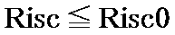
エンジン制御ダイヤル38は、回転可能なダイヤルによって構成され、ダイヤルの回転位置に応じてエンジン21の目標回転数ωeを設定する。このエンジン制御ダイヤル38は、キャブ7内に位置して、オペレータによって回転操作され、目標回転数ωeに応じた指令信号を出力する。
次に、HCU36の具体的な構成について、図4を参照して説明する。HCU36は、発電電動機要求出力演算部40と、最大出力演算部50と、出力指令演算部60とを備えている。このとき、最大出力演算部50および出力指令演算部60は、発電電動機要求出力演算部40からの出力の要求に基づいて、蓄電率SOCが使用下限値SOC1または使用上限値SOC2を超えず、かつ電流二乗積算比率Riscが上限値Risc2を超えないように、蓄電装置31の出力を制御する出力制御部を構成している。
まず、発電電動機要求出力演算部40の具体的な構成について、図5ないし図8を参照して説明する。
発電電動機要求出力演算部40は、出力要求部を構成している。このため、発電電動機要求出力演算部40は、蓄電率SOCと電流二乗積算比率Riscが許容範囲内にあるときに、蓄電率SOCと電流二乗積算比率Riscが許容範囲から逸脱しないように蓄電装置31の出力を要求する。また、発電電動機要求出力演算部40は、蓄電率SOCが許容範囲を超えて目標値SOC0から逸脱したとき(SOC<SOC0-X1またはSOC>SOC0-X2)に、電流二乗積算比率Riscが中間値Risc0から逸脱するのを許容して、蓄電率SOCが目標値SOC0に近付くように蓄電装置31の出力を要求する。さらに、発電電動機要求出力演算部40は、電流二乗積算比率Riscが許容範囲を超えて中間値Risc0から逸脱したとき(Risc>Risc0)に、蓄電率SOCが目標値SOC0から逸脱するのを許容して、電流二乗積算比率Riscが中間値Risc0に近付くように蓄電装置31の出力を要求する。
発電電動機要求出力演算部40は、蓄電装置31の状況に応じて、発電電動機27を適切に動作(力行動作または発電動作)させるために、発電電動機要求出力Pmg1を決定する。発電電動機要求出力演算部40は、蓄電率SOCが目標値SOC0を下回り(SOC<SOC0)、かつ電流二乗積算比率Riscが許容範囲内にある場合に発電電動機27に発電を要求する発電要求部40Aと、蓄電率SOCが目標値SOC0を上回り(SOC>SOC0)、かつ電流二乗積算比率Riscが許容範囲内にある場合に発電電動機27に力行を要求する力行要求部40Bとを有している。これに加え、発電電動機要求出力演算部40は、電流二乗積算比率Riscが上限値Risc2に近付くに従って出力を低下させて発電電動機27に発電または力行を要求する出力低下要求部43Bをさらに有している。
図5に示すように、発電電動機要求出力演算部40は、蓄電率偏差演算部41と、蓄電率要求出力演算部42と、電流二乗積算比率要求出力演算部43と、飽和演算部44と、加算器45とを備えている。この発電電動機要求出力演算部40には、蓄電率SOCと、電流二乗積算比率Riscと、旋回電動モータ出力P0erとが入力される。
蓄電率偏差演算部41は、蓄電率SOCと目標蓄電率設定値である目標値SOC0との差を演算し、蓄電率偏差ΔSOC(ΔSOC=SOC-SOC0)を出力する。
蓄電率要求出力演算部42は、蓄電率SOCに応じて、発電電動機27に要求する出力として、蓄電率要求出力Psoc1を出力する。具体的には、蓄電率要求出力演算部42は、蓄電率偏差ΔSOCに基づいて、蓄電率要求出力Psoc1を演算するために、例えば図6に示すようなテーブルT1を有する。
蓄電率偏差ΔSOCが0となったとき(ΔSOC=0)には、テーブルT1は、蓄電率要求出力Psoc1を最小値(例えばPsoc1=0kW)に設定する。このとき、蓄電率SOCは目標値SOC0となっており、発電電動機27の動作は不要である。
蓄電率偏差ΔSOCが0から下側余裕X1までの範囲で低下したとき(-X1≦ΔSOC<0)には、テーブルT1は、蓄電率偏差ΔSOCの絶対値の大きさに応じて、蓄電率要求出力Psoc1を発電側に増加させた値(負の値)に設定する。このとき、蓄電率SOCは、目標値SOC0よりも低下しており、発電電動機27の発電動作によって目標値SOC0に近付けるのが好ましい。
蓄電率偏差ΔSOCが下側余裕X1よりも低下したとき(-X1>ΔSOC)には、テーブルT1は、蓄電率要求出力Psoc1を発電側で最大値Y11(例えばPsoc1=-30kW)に設定する。このとき、蓄電率SOCは、目標値SOC0よりも下側余裕X1を超えて低下しており、発電電動機27の発電動作によって速やかに充電する必要である。
蓄電率偏差ΔSOCが0から上側余裕X2までの範囲で上昇したとき(0<ΔSOC≦X2)には、テーブルT1は、蓄電率偏差ΔSOCの絶対値の大きさに応じて、蓄電率要求出力Psoc1を力行側に増加させた値(正の値)に設定する。このとき、蓄電率SOCは、目標値SOC0よりも上昇しており、発電電動機27の力行動作によって目標値SOC0に近付けるのが好ましい。
蓄電率偏差ΔSOCが上側余裕X2よりも上昇したとき(X2<ΔSOC)には、テーブルT1は、蓄電率要求出力Psoc1を力行側で最大値Y12(例えばPsoc1=30kW)に設定する。このとき、蓄電率SOCは、目標値SOC0よりも上側余裕X2を超えて上昇しており、発電電動機27の力行動作によって速やかに放電する必要である。
このように蓄電率要求出力演算部42は、蓄電率偏差ΔSOCが負値の場合(ΔSOC<0)には、発電要求となった蓄電率要求出力Psoc1を出力する。従って、テーブルT1のうち負値の蓄電率偏差ΔSOCに対応した部分は、発電出力要求部42Aを構成している。また、発電出力要求部42Aは、蓄電率SOCが許容範囲外にある場合に最大値Y11の蓄電率要求出力Psoc1で発電要求を行う最大発電出力要求部42A1と、蓄電率SOCが許容範囲内にある場合に、蓄電率SOCが許容範囲外にあるときに比べて蓄電率要求出力Psoc1を低下させて発電要求を行う発電出力低下要求部42A2とを有している。
一方、蓄電率要求出力演算部42は、蓄電率偏差ΔSOCが正値の場合(ΔSOC>0)には、力行要求となった蓄電率要求出力Psoc1を出力する。従って、テーブルT1のうち正値の蓄電率偏差ΔSOCに対応した部分は、力行出力要求部42Bを構成している。また、力行出力要求部42Bは、蓄電率SOCが許容範囲外にある場合に最大値Y12の蓄電率要求出力Psoc1で力行要求を行う最大力行出力要求部42B1と、蓄電率SOCが許容範囲内にある場合に、蓄電率SOCが許容範囲外にあるときに比べて蓄電率要求出力Psoc1を低下させて力行要求を行う力行出力低下要求部42B2とを有している。
なお、蓄電率偏差ΔSOCが0から下側余裕X1までの間では、蓄電率要求出力演算部42は、蓄電率偏差ΔSOCの絶対値の大きさに比例して、蓄電率要求出力Psoc1を発電側に増加させるものとした。また、蓄電率偏差ΔSOCが0から上側余裕X2までの間では、蓄電率要求出力演算部42は、蓄電率偏差ΔSOCの絶対値の大きさに比例して、蓄電率要求出力Psoc1を力行側に増加させるものとした。本発明はこれに限らず、蓄電率偏差ΔSOCが下側余裕X1から上側余裕X2までの間では、蓄電率要求出力演算部42は、蓄電率偏差ΔSOCの絶対値の大きさに対して、蓄電率要求出力Psoc1の大きさを単調増加させればよい。このため、蓄電率要求出力演算部42には、比例特性に限らず、各種の特性が採用可能である。
電流二乗積算比率要求出力演算部43は、電流二乗積算比率Riscに応じて発電電動機27に要求する出力として、電流二乗積算比率要求出力Prisc1を出力する。具体的には、電流二乗積算比率要求出力演算部43は、電流二乗積算比率Riscに基づいて、電流二乗積算比率要求出力Prisc1を演算するために、例えば図7に示すようなテーブルT2を有する。
電流二乗積算比率Riscが中間値Risc0以下となったとき(Risc≦Risc0)には、テーブルT2は、電流二乗積算比率要求出力Prisc1を最大値Y22(例えばPrisc1=30kW)に設定する。このとき、電流二乗積算比率要求出力Prisc1は、上限値Risc2に対して余裕があるため、発電電動機27を最大範囲で力行動作または発電動作させることが可能である。
電流二乗積算比率Riscが中間値Risc0よりも上昇して上限値Risc2に近付いたとき(Risc0<Risc<Risc2)には、テーブルT2は、電流二乗積算比率Riscが上限値Risc2に近付くに従って、電流二乗積算比率要求出力Prisc1を最大値Y22から減少させた値に設定する。
電流二乗積算比率Riscが上限値Risc2となったとき(Risc=Risc2)には、テーブルT2は、電流二乗積算比率要求出力Prisc1を最小値Y21(例えばPrisc1=0kW)に設定する。このとき、電流二乗積算比率要求出力Prisc1をこれ以上増加させることができないため、発電電動機27の力行動作および発電動作を停止させて、蓄電装置31を休止させる必要がある。
このように電流二乗積算比率要求出力演算部43は、電流二乗積算比率Riscが許容範囲内にある場合に最大値Y22の電流二乗積算比率要求出力Prisc1で発電または力行を要求する最大出力要求部43Aと、電流二乗積算比率Riscが許容範囲外にある場合に、電流二乗積算比率Riscが許容範囲内にあるときに比べて蓄電率要求出力Psoc1を低下させて発電または力行を要求する出力低下要求部43Bとを有している。
なお、電流二乗積算比率Riscが中間値Risc0から上限値Risc2までの間では、電流二乗積算比率要求出力演算部43は、電流二乗積算比率Riscの大きさに比例して、電流二乗積算比率要求出力Prisc1を減少させるものとした。本発明はこれに限らず、電流二乗積算比率Riscが中間値Risc0から上限値Risc2までの間では、電流二乗積算比率要求出力演算部43は、電流二乗積算比率Riscの大きさに対して、電流二乗積算比率要求出力Prisc1の大きさを単調減少させればよい。このため、電流二乗積算比率要求出力演算部43には、比例特性に限らず、各種の特性が採用可能である。
飽和演算部44は、蓄電率要求出力Psoc1と、電流二乗積算比率要求出力Prisc1とに基づいて、蓄電装置31の状態に基づく蓄電装置要求出力Pmg10を算出する。具体的には、飽和演算部44には、蓄電率要求出力Psoc1と、電流二乗積算比率要求出力Prisc1とに加えて、反転入力部44Aによって電流二乗積算比率要求出力Prisc1の符号が反転した値(-Prisc1)が入力される。このとき、電流二乗積算比率要求出力Prisc1は、全て正の値になっている。電流二乗積算比率要求出力Prisc1は、力行側の制限値となる上限値を示している。電流二乗積算比率要求出力Prisc1の負の値(-Prisc1)は、発電側の制限値となる下限値を示している。
このため、上限値Prisc1から下限値(-Prisc1)の範囲内に蓄電率要求出力Psoc1があるとき(-Prisc1<Psoc1<Prisc1)には、飽和演算部44は、蓄電率要求出力Psoc1と同じ値の蓄電装置要求出力Pmg10を出力する。一方、蓄電率要求出力Psoc1が上限値Prisc1よりも上昇したとき(Prisc1<Psoc1)には、飽和演算部44は、上限値Prisc1と同じ値の蓄電装置要求出力Pmg10を出力する。同様に、蓄電率要求出力Psoc1が下限値(-Prisc1)よりも低下したとき(-Prisc1>Psoc1)には、飽和演算部44は、下限値(-Prisc1)と同じ値の蓄電装置要求出力Pmg10を出力する。
これにより、発電電動機要求出力演算部40は、蓄電率SOCが目標値SOC0から逸脱した大きさと、電流二乗積算比率Riscが中間値Risc0から上限値Risc2に向けて逸脱した大きさに応じて、図8に示す蓄電装置要求出力Pmg10を出力する。
このとき、発電要求部40Aは、発電出力要求部42A、最大出力要求部43Aおよび飽和演算部44によって構成されている。力行要求部40Bは、力行出力要求部42B、最大出力要求部43Aおよび飽和演算部44によって構成されている。
このため、発電要求部40Aは、蓄電率SOCが許容範囲内にある場合に、蓄電率SOCが許容範囲外にあるときに比べて蓄電率要求出力Psoc1を低下させて発電要求を行う発電出力低下要求部42A2を有している。力行要求部40Bは、蓄電率SOCが許容範囲内にある場合に、蓄電率SOCが許容範囲外にあるときに比べて蓄電率要求出力Psoc1を低下させて力行要求を行う力行出力低下要求部42B2を有している。
蓄電率要求出力演算部42、電流二乗積算比率要求出力演算部43、飽和演算部44等は、上述した演算処理を実行する。これらの演算処理の内容を、図8を参照して具体的に説明する。
(1).SOC<SOC0のとき
この状態では、蓄電装置31を充電して、蓄電率SOCを目標値SOC0に近付けるのが好ましい。ここで、電流二乗積算比率Riscが上限値Risc2未満であるとき(Risc<Risc2)には、電流二乗積算比率Riscには余裕がある。このため、飽和演算部44は、発電電動機27に対して発電動作を要求する蓄電装置要求出力Pmg10を出力する。
この状態では、蓄電装置31を充電して、蓄電率SOCを目標値SOC0に近付けるのが好ましい。ここで、電流二乗積算比率Riscが上限値Risc2未満であるとき(Risc<Risc2)には、電流二乗積算比率Riscには余裕がある。このため、飽和演算部44は、発電電動機27に対して発電動作を要求する蓄電装置要求出力Pmg10を出力する。
特に、蓄電率SOCが目標値SOC0よりも大きく低下している状態(SOC<SOC0-X1)であり、かつ、電流二乗積算比率Riscが中間値Risc0以下のとき(Risc≦Risc0)には、飽和演算部44は、蓄電装置要求出力Pmg10を、発電電動機27の仕様上の最大発電出力に設定する。このとき、飽和演算部44は、フルパワーでの発電を要求する。
一方、蓄電率SOCが目標値SOC0よりも大きく低下している状態(SOC<SOC0-X1)であっても、電流二乗積算比率Riscが中間値Risc0よりも上限値Risc2に近付いたとき(Risc0<Risc<Risc2)には、電流二乗積算比率Riscに応じて充電電力を制限する必要がある。そこで、飽和演算部44は、電流二乗積算比率Riscが中間値Risc0よりも大きくなるに従って、蓄電装置要求出力Pmg10を、最大発電出力から低下させる。このとき、飽和演算部44は、ハーフパワーでの発電を要求する。
電流二乗積算比率Riscが上限値Risc2となったとき(Risc=Risc2)には、飽和演算部44は、蓄電装置要求出力Pmg10を、最小値(0kW)に設定する。このとき、飽和演算部44は、発電および力行の要求を停止する。
なお、中間値Risc0は、必ずしも50%である必要はない。例えば、電流二乗積算比率Riscが中間値Risc0で、かつ蓄電率SOCが下限値SOC1にあるときに、蓄電率SOCが目標値SOC0に到達するまで、車体が非操作の状態で充電すると仮定する。このような充電状態で、電流二乗積算比率Riscが上限値Risc2付近まで増加しないように、中間値Risc0をチューニングするのが好ましい。一例として、ここでは、中間値Risc0を70%としている。
(2).SOC>SOC0のとき
この状態では、蓄電装置31を放電して、蓄電率SOCを目標値SOC0に近付けるのが好ましい。ここで、電流二乗積算比率Riscが上限値Risc2未満であるとき(Risc<Risc2)には、電流二乗積算比率Riscには余裕がある。このため、飽和演算部44は、発電電動機27に対して力行動作を要求する蓄電装置要求出力Pmg10を出力する。
この状態では、蓄電装置31を放電して、蓄電率SOCを目標値SOC0に近付けるのが好ましい。ここで、電流二乗積算比率Riscが上限値Risc2未満であるとき(Risc<Risc2)には、電流二乗積算比率Riscには余裕がある。このため、飽和演算部44は、発電電動機27に対して力行動作を要求する蓄電装置要求出力Pmg10を出力する。
特に、蓄電率SOCが目標値SOC0よりも大きく上昇している状態(SOC>SOC0+X2)であり、かつ、電流二乗積算比率Riscが中間値Risc0以下のとき(Risc≦Risc0)には、飽和演算部44は、蓄電装置要求出力Pmg10を、発電電動機27の仕様上の最大力行出力に設定する。このとき、飽和演算部44は、フルパワーでの力行を要求する。
一方、蓄電率SOCが目標値SOC0よりも大きく上昇している状態(SOC>SOC0+X2)であっても、電流二乗積算比率Riscが中間値Risc0よりも上限値Risc2に近付いたとき(Risc0<Risc<Risc2)には、電流二乗積算比率Riscに応じて力行電力(放電電力)を制限する必要がある。そこで、飽和演算部44は、電流二乗積算比率Riscが中間値Risc0よりも大きくなるに従って、蓄電装置要求出力Pmg10を、最大力行出力から低下させる。このとき、飽和演算部44は、ハーフパワーでの力行を要求する。
電流二乗積算比率Riscが上限値Risc2となったとき(Risc=Risc2)には、飽和演算部44は、蓄電装置要求出力Pmg10を、最小値(0kW)に設定する。このとき、飽和演算部44は、発電および力行の要求を停止する。
なお、中間値Risc0は、必ずしも50%である必要はない。例えば、電流二乗積算比率Riscが中間値Risc0で、かつ蓄電率SOCが上限値SOC2にあるときに、蓄電率SOCが目標値SOC0に到達するまで、車体が非操作の状態で放電すると仮定する。このような放電状態で、電流二乗積算比率Riscが上限値Risc2付近まで増加しないように、中間値Risc0をチューニングするのが好ましい。一例として、ここでは、中間値Risc0を70%とする。
(3).SOC≒SOC0のとき
この状態では、蓄電率SOCは、目標値SOC0となっている。仮に、蓄電率SOCが目標値SOC0から逸脱したとしても、この状態では、蓄電率偏差ΔSOCは小さい値である。従って、電流二乗積算比率Riscの値に拘らず、飽和演算部44は、蓄電率SOCが目標値SOC0に収束するように、蓄電装置要求出力Pmg10を、十分に小さな値の放電電力または充電電力に設定する。なお、蓄電率SOCと目標値SOC0とが一致するとき(SOC=SOC0)には、飽和演算部44は、発電および力行の要求を停止する。
この状態では、蓄電率SOCは、目標値SOC0となっている。仮に、蓄電率SOCが目標値SOC0から逸脱したとしても、この状態では、蓄電率偏差ΔSOCは小さい値である。従って、電流二乗積算比率Riscの値に拘らず、飽和演算部44は、蓄電率SOCが目標値SOC0に収束するように、蓄電装置要求出力Pmg10を、十分に小さな値の放電電力または充電電力に設定する。なお、蓄電率SOCと目標値SOC0とが一致するとき(SOC=SOC0)には、飽和演算部44は、発電および力行の要求を停止する。
加算器45には、蓄電装置31の状態に基づく蓄電装置要求出力Pmg10と、反転入力部45Aによって旋回電動モータ出力P0erの符号が反転した値(-P0er)とが入力される。加算器45は、蓄電装置要求出力Pmg10に対して、旋回電動モータ出力P0erに-1を掛けた値を加算し、この加算値を算出する。発電要求と力行要求に対して、旋回電動モータ出力P0erに応じた分が優先的に実行される。加算器45は、この点を考慮した処理を行っている。
具体的に説明すると、蓄電装置要求出力Pmg10が力行要求で、かつ旋回電動モータ33が力行状態では、旋回電動モータ出力P0erに応じた値を、放電電力である蓄電装置要求出力Pmg10から低下させる。蓄電装置要求出力Pmg10が発電要求で、かつ旋回電動モータ33が発電状態では、旋回電動モータ出力P0erに応じた値を、発電電力である蓄電装置要求出力Pmg10から低下させる。
一方、蓄電装置要求出力Pmg10が力行要求で、かつ旋回電動モータ33が発電状態では、旋回電動モータ出力P0erに応じた値を、放電電力である蓄電装置要求出力Pmg10から上昇させる。蓄電装置要求出力Pmg10が発電要求で、かつ旋回電動モータ33が力行状態では、旋回電動モータ出力P0erに応じた値を、発電電力である蓄電装置要求出力Pmg10から上昇させる。
加算器45は、発電電動機要求出力Pmg1を加算値に設定する。但し、加算器45は、力行側の加算値が最大力行出力を超えるときには、発電電動機要求出力Pmg1を最大力行出力に設定する。加算器45は、発電側の加算値が最大発電出力を超えるときには、発電電動機要求出力Pmg1を最大発電出力に設定する。加算器45は、旋回電動モータ出力P0erを考慮した最終的な発電電動機要求出力Pmg1を出力する。
次に、最大出力演算部50の具体的な構成について、図9および図10を参照して説明する。
最大出力演算部50は、出力制御部の一部を構成している。この最大出力演算部50は、蓄電率SOCが使用下限値SOC1に到達した場合に発電電動機27の力行を禁止する力行禁止部としての蓄電率力行制限ゲイン演算部52Aと、蓄電率SOCが使用上限値SOC2に到達した場合に発電電動機27の発電を禁止する発電禁止部としての蓄電率発電制限ゲイン演算部52Bとを有している。これに加え、最大出力演算部50は、電流二乗積算比率Riscが上限値Risc2に到達した場合は発電電動機27の力行と発電をいずれも禁止する力行発電禁止部としての電流二乗積算比率出力制限ゲイン演算部52Cを有している。
図9に示すように、最大出力演算部50は、エンジン最大出力演算部51と、発電電動機出力制限ゲイン演算部52と、発電電動機最大出力演算部53とを有している。この最大出力演算部50には、エンジン目標回転数ωeと、蓄電率SOCと、電流二乗積算比率Riscとが入力される。
エンジン最大出力演算部51は、エンジン目標回転数ωeとエンジン最大出力Pe-maxとの対応関係を示したテーブル(図示せず)を有している。このとき、エンジン最大出力Pe-maxは、エンジン目標回転数ωeでエンジン21が駆動したときの、エンジン21から供給可能な最大出力を示している。エンジン最大出力演算部51は、エンジン目標回転数ωeに基づいてエンジン最大出力Pe-maxを演算し、算出したエンジン最大出力Pe-maxを出力する。
図10に示すように、発電電動機出力制限ゲイン演算部52は、蓄電率力行制限ゲイン演算部52Aと、蓄電率発電制限ゲイン演算部52Bと、電流二乗積算比率出力制限ゲイン演算部52Cと、最小値選択部52D,52Eとを有している。発電電動機出力制限ゲイン演算部52には、蓄電率SOCと、電流二乗積算比率Riscとが入力される。
蓄電率力行制限ゲイン演算部52Aは、蓄電率SOCに基づいて蓄電率力行制限ゲインKmgm0を演算するために、テーブルT3を有する。このとき、蓄電率力行制限ゲインKmgm0は、発電電動機27の力行によって蓄電率SOCが下限値a1まで低下するのを抑制するために、発電電動機27の力行出力を制限するものである。蓄電率力行制限ゲイン演算部52Aは、テーブルT3を用いて蓄電率SOCに応じた蓄電率力行制限ゲインKmgm0を演算する。なお、下限値a1は、使用下限値SOC1と同じ値である。
テーブルT3は、蓄電率SOCが適正使用範囲の下限値a1まで低下すると、蓄電率力行制限ゲインKmgm0を最小値(例えばKmgm0=0)に設定する。テーブルT3は、蓄電率SOCが閾値となる下側の適正基準値a2よりも上昇すると、蓄電率力行制限ゲインKmgm0を最大値(例えばKmgm0=1)に設定する。また、蓄電率SOCが下限値a1と適正基準値a2の間の値となるときには、テーブルT3は、蓄電率SOCが低下するに従って、蓄電率力行制限ゲインKmgm0を低下させる。即ち、蓄電率SOCが適正基準値a2よりも低下すると、テーブルT3は、適正基準値a2からの低下度合いに応じて、蓄電率力行制限ゲインKmgm0を最小値と最大値との間の値に設定する。ここで、適正基準値a2は、下限値a1から予め決められた余裕を持って大きな値に設定されている。例えば下限値a1が30%となるときに、適正基準値a2は35%程度の値に設定されている。なお、適正基準値a2は、蓄電率SOCの許容範囲の下限値と同じ値になる場合を例示したが、これらは互いに異なる値でもよい。
蓄電率発電制限ゲイン演算部52Bは、蓄電率SOCに基づいて蓄電率発電制限ゲインKmgg0を演算するために、テーブルT4を有する。このとき、蓄電率発電制限ゲインKmgg0は、発電電動機27の発電によって蓄電率SOCが上限値a4まで上昇するのを抑制するために、発電電動機27の発電出力を制限するものである。蓄電率発電制限ゲイン演算部52Bは、テーブルT4を用いて蓄電率SOCに応じた蓄電率発電制限ゲインKmgg0を演算する。なお、上限値a4は、使用上限値SOC2と同じ値である。
テーブルT4は、蓄電率SOCが適正使用範囲の上限値a4まで上昇すると、蓄電率発電制限ゲインKmgg0を最小値(例えばKmgg0=0)に設定する。テーブルT4は、蓄電率SOCが閾値となる上側の適正基準値a3よりも低下すると、蓄電率発電制限ゲインKmgg0を最大値(例えばKmgg0=1)に設定する。また、蓄電率SOCが上限値a4と適正基準値a3の間の値となるときには、テーブルT4は、蓄電率SOCが上昇するに従って、蓄電率力行制限ゲインKmgm0を低下させる。即ち、蓄電率SOCが適正基準値a3よりも上昇すると、テーブルT4は、適正基準値a3からの上昇度合いに応じて、蓄電率発電制限ゲインKmgg0を最小値と最大値との間の値に設定する。ここで、適正基準値a3は、上限値a4から予め決められた余裕を持って小さな値に設定されている。例えば上限値a4が70%となるときに、適正基準値a3は65%程度の値に設定されている。なお、適正基準値a3は、蓄電率SOCの許容範囲の上限値と同じ値になる場合を例示したが、これらは互いに異なる値でもよい。
電流二乗積算比率出力制限ゲイン演算部52Cは、電流二乗積算比率Riscに基づいて電流二乗積算比率出力制限ゲインKrisc0を演算するために、テーブルT5を有する。このとき、電流二乗積算比率出力制限ゲインKrisc0は、発電電動機27の力行および発電によって電流二乗積算比率Riscが上限値b2まで上昇するのを抑制するために、発電電動機27の発電出力および力行出力を制限するものである。電流二乗積算比率出力制限ゲイン演算部52Cは、テーブルT5を用いて電流二乗積算比率Riscに応じた電流二乗積算比率出力制限ゲインKrisc0を演算する。
テーブルT5は、電流二乗積算比率Riscが適正使用範囲の上限値b2まで上昇すると、電流二乗積算比率出力制限ゲインKrisc0を最小値(例えばKrisc0=0)に設定する。テーブルT5は、電流二乗積算比率Riscが閾値となる適正基準値b1よりも低下すると、電流二乗積算比率出力制限ゲインKrisc0を最大値(例えばKrisc0=1)に設定する。また、電流二乗積算比率Riscが上限値b2と適正基準値b1の間の値となるときには、テーブルT5は、電流二乗積算比率Riscが上昇するに従って、電流二乗積算比率出力制限ゲインKrisc0を低下させる。即ち、電流二乗積算比率Riscが適正基準値b1よりも上昇すると、テーブルT5は、適正基準値b1からの上昇度合いに応じて、電流二乗積算比率出力制限ゲインKrisc0を最小値と最大値との間の値に設定する。ここで、適正基準値b1は、上限値b2から予め決められた余裕を持って小さな値に設定されている。例えば上限値b2が100%となるときに、適正基準値b1は95%程度の値に設定されている。なお、上限値b2は、電流二乗積算比率Riscの限界値(上限値Risc2)と同じ値である。また、適正基準値b1は、電流二乗積算比率Riscの許容範囲の上限値(中間値Risc0)と異なる値になる場合を例示したが、これらは互いに同じ値でもよい。
最小値選択部52Dは、蓄電率力行制限ゲイン演算部52Aによる蓄電率力行制限ゲインKmgm0と、電流二乗積算比率出力制限ゲイン演算部52Cによる電流二乗積算比率出力制限ゲインKrisc0とを比較する。最小値選択部52Dは、蓄電率力行制限ゲインKmgm0と、電流二乗積算比率出力制限ゲインKrisc0とのうちで最小の値を選択し、発電電動機力行制限ゲインKmgmとして出力する。
最小値選択部52Eは、蓄電率発電制限ゲイン演算部52Bによる蓄電率発電制限ゲインKmgg0と、電流二乗積算比率出力制限ゲイン演算部52Cによる電流二乗積算比率出力制限ゲインKrisc0とを比較する。最小値選択部52Eは、蓄電率発電制限ゲインKmgg0と、電流二乗積算比率出力制限ゲインKrisc0とのうちで最小の値を選択し、発電電動機発電制限ゲインKmggとして出力する。
発電電動機最大出力演算部53は、エンジン最大出力演算部51と同様に、エンジン目標回転数ωeに対する発電電動機27の力行最大出力と、発電最大出力のテーブル(図示せず)を有している。発電電動機最大出力演算部53は、エンジン21の目標回転数ωeに基づいて、発電電動機27の力行最大出力および発電最大出力を算出する。発電電動機最大出力演算部53は、目標回転数ωeから決定した力行最大出力に発電電動機力行制限ゲインKmgmを作用(乗算)させた値を、発電電動機最大力行出力Pmgm-maxとして出力する。発電電動機最大出力演算部53は、目標回転数ωeから決定した発電最大出力に発電電動機発電制限ゲインKmggを作用(乗算)させた値を、発電電動機最大発電出力Pmgg-maxとして出力する。
次に、出力指令演算部60の具体的な構成について、図11ないし図14を参照して説明する。
図11に示すように、出力指令演算部60は、ポンプ推定入力演算部61と、発電電動機力行発電要求判定部62と、発電電動機力行出力演算部63と、発電電動機発電出力演算部64と、発電電動機出力指令演算部65と、エンジン出力指令演算部66とを有している。この出力指令演算部60には、旋回速度Vrと、各レバー操作量OA(OAr,OAbm,OAam,OAbk)と、その他車体情報VIと、蓄電率SOCと、電流二乗積算比率Riscと、発電電動機要求出力Pmg1と、エンジン最大出力Pe-maxと、発電電動機最大力行出力Pmgm-maxと、発電電動機最大発電出力Pmgg-maxとが入力される。
図12に示すように、ポンプ推定入力演算部61は、各レバー操作量OAに応じて車体を動作させたために必要なポンプ推定入力Ppと旋回電動モータ出力指令Perとを演算する。ポンプ推定入力演算部61は、ポンプ推定入力Ppと旋回電動モータ出力指令Perとを演算するときに、旋回速度Vrと、その他車体情報VIと、蓄電率SOCと、電流二乗積算比率Riscと、エンジン最大出力Pe-maxと、発電電動機最大力行出力Pmgm-maxとを考慮する。このため、ポンプ推定入力演算部61には、旋回速度Vrと、その他車体情報VIと、蓄電率SOCと、電流二乗積算比率Riscと、エンジン最大出力Pe-maxと、発電電動機最大力行出力Pmgm-maxと、各レバー操作量OAとが入力される。なお、以降では、その他車体情報VIについては、省いて説明する。ポンプ推定入力演算部61の具体的に構成については、後述する。
発電電動機力行発電要求判定部62には、発電電動機要求出力Pmg1が入力される。発電電動機要求出力Pmg1が正の値の場合(Pmg1>0)、発電電動機力行発電要求判定部62は、発電電動機力行要求出力Pmgm1を発電電動機要求出力Pmg1の値に設定する(Pmgm1=Pmg1)と共に、発電電動機発電要求出力Pmgg1を0に設定する(Pmgg1=0)。逆に、発電電動機要求出力Pmg1が負の値の場合(Pmg1<0)、発電電動機力行発電要求判定部62は、発電電動機力行要求出力Pmgm1を0に設定する(Pmgm1=0)と共に、発電電動機発電要求出力Pmgg1を発電電動機要求出力Pmg1の値に設定する(Pmgm1=Pmg1)。発電電動機力行発電要求判定部62は、これらの発電電動機力行要求出力Pmgm1と発電電動機発電要求出力Pmgg1とを出力する。
図13に示すように、発電電動機力行出力演算部63は、減算器63Aと、最大値選択部63Bと、最小値選択部63Cとを有している。発電電動機力行出力演算部63には、ポンプ推定入力Ppと、エンジン最大出力Pe-maxと、発電電動機最大力行出力Pmgm-maxと、発電電動機力行要求出力Pmgm1とが入力される。
減算器63Aは、ポンプ推定入力Ppからエンジン最大出力Pe-maxを減算し、この減算値を出力する。最大値選択部63Bは、減算器63Aからの出力と、0と、発電電動機力行要求出力Pmgm1とを比較する。最大値選択部63Bは、減算器63Aからの出力と、0と、発電電動機力行要求出力Pmgm1とのうち最大値を選択して、発電電動機力行出力Pmgm10として出力する。このとき、発電電動機力行出力Pmgm10は、0または正の値になる(Pmgm10≧0)。
最小値選択部63Cは、発電電動機力行出力Pmgm10と発電電動機最大力行出力Pmgm-maxとを比較する。最小値選択部63Cは、発電電動機力行出力Pmgm10と発電電動機最大力行出力Pmgm-maxとのうち最小の値を選択し、発電電動機力行出力指令Pmgmとして出力する。
このように、発電電動機力行出力演算部63は、ポンプ推定入力Ppとエンジン最大出力Pe-maxとを比較する。発電電動機力行出力演算部63は、ポンプ推定入力Ppがエンジン最大出力Pe-maxよりも大きい場合(Pp>Pe-max)は、ポンプ推定入力Ppとエンジン最大出力Pe-maxとの差を発電電動機力行出力指令Pmgmとする。但し、発電電動機力行出力指令Pmgmは、発電電動機最大力行出力Pmgm-maxよりも大きくならないように調整される。
一方、エンジン最大出力Pe-maxがポンプ推定入力Ppよりも大きい場合(Pp<Pe-max)は、発電電動機最大力行出力Pmgm-maxと発電電動機力行要求出力Pmgm1とのうち最小のものを選択し、発電電動機力行出力指令Pmgmとする。
これにより、発電電動機力行出力演算部63は、油圧負荷に対してエンジン21の出力で不足する部分を発電電動機27の力行出力によって担保する。その上で、発電電動機力行出力演算部63は、発電電動機力行要求出力Pmgm1を満たすように、発電電動機27の力行動作を制御する。
図14に示すように、発電電動機発電出力演算部64は、減算器64Aと、最大値選択部64B,64D,64Eと、発電電力変換部64Cとを有している。発電電動機発電出力演算部64には、ポンプ推定入力Ppと、エンジン最大出力Pe-maxと、発電電動機最大発電出力Pmgg-maxと、発電電動機発電要求出力Pmgg1とが入力される。
減算器64Aは、エンジン最大出力Pe-maxからポンプ推定入力Ppを減算し、この減算値を出力する。最大値選択部64Bは、減算器64Aからの出力と0とを比較する。最大値選択部64Bは、減算器64Aからの出力と0とのうち最大値を選択する。このとき、最大値選択部64Bは、0または正の値を出力する。最大値選択部64Bからの出力は、発電電力変換部64Cによって-1が乗算され、負の値に変換される。これにより、発電電力変換部64Cは、エンジン最大出力Pe-maxとポンプ推定入力Ppとの差に応じた大きさとなった第1の発電電動機発電出力Pmgg10を出力する。このとき、第1の発電電動機発電出力Pmgg10は、0または負の値になる(Pmgg10≦0)。
最大値選択部64Dは、発電電動機発電要求出力Pmgg1と発電電動機最大発電出力Pmgg-maxとを比較する。最大値選択部64Dは、発電電動機発電要求出力Pmgg1と発電電動機最大発電出力Pmgg-maxとのうち、大きい方を選択する。ここで、発電電動機発電要求出力Pmgg1と発電電動機最大発電出力Pmgg-maxは、いずれも負の値である。従って、最大値選択部64Dは、発電電動機発電要求出力Pmgg1と発電電動機最大発電出力Pmgg-maxとのうち、0に近い値の方(絶対値の小さい方)を選択する。最大値選択部64Dは、発電電動機発電要求出力Pmgg1と発電電動機最大発電出力Pmgg-maxとのうち選択した方を、第2の発電電動機発電出力Pmgg20として出力する。
最大値選択部64Eは、第1の発電電動機発電出力Pmgg10と第2の発電電動機発電出力Pmgg20とを比較する。最大値選択部64Eは、第1の発電電動機発電出力Pmgg10と第2の発電電動機発電出力Pmgg20とのうち、大きい方を選択する。ここで、第1の発電電動機発電出力Pmgg10と第2の発電電動機発電出力Pmgg20は、いずれも負の値である。このため、最大値選択部64Eは、第1の発電電動機発電出力Pmgg10と第2の発電電動機発電出力Pmgg20とのうち、0に近い値の方(絶対値の小さい方)を選択する。最大値選択部64Eは、第1の発電電動機発電出力Pmgg10と第2の発電電動機発電出力Pmgg20とのうち選択した方を、発電電動機発電出力指令Pmggとして出力する。
このように、発電電動機発電出力演算部64は、ポンプ推定入力Ppとエンジン最大出力Pe-maxとを比較する。発電電動機発電出力演算部64は、ポンプ推定入力Ppがエンジン最大出力Pe-maxよりも大きい場合(Pp>Pe-max)は、0となった発電電動機発電出力指令Pmggを出力する。この場合、エンジン21は、油圧負荷への対応で全ての出力が消費されるから、発電動作を行う余裕がない。このため、発電電動機発電出力指令Pmggは0に設定され、発電電動機27が発電動作を行うことはない。
一方、エンジン最大出力Pe-maxがポンプ推定入力Ppよりも大きい場合(Pp<Pe-max)は、エンジン最大出力Pe-maxとポンプ推定入力Ppとの差と、発電電動機最大力行出力Pmgm-maxと、発電電動機力行要求出力Pmgm1とのうち、その絶対値が最小のものを選択し、発電電動機力行出力指令Pmgmとする。
これにより、発電電動機発電出力演算部64は、油圧負荷に対応しながら、可能な限り発電電動機力行要求出力Pmgm1を満たすように、発電電動機27の発電動作を制御する。
発電電動機出力指令演算部65は、発電電動機力行出力指令Pmgmと発電電動機発電出力指令Pmggとを加算する。発電電動機出力指令演算部65は、この加算値を、発電電動機出力指令Pmgとして出力する。
エンジン出力指令演算部66は、ポンプ推定入力Ppから発電電動機出力指令Pmgを減算する。エンジン出力指令演算部66は、この減算値を、エンジン出力指令Peとして出力する。
出力指令演算部60は、出力制御部の一部を構成している。この出力指令演算部60は、発電電動機要求出力演算部40からの出力の要求に加えて、操作量センサ9A~11Aによって検出したレバー操作量OAに基づいて、蓄電装置31の出力を制御する。また、出力指令演算部60のポンプ推定入力演算部61は、各レバー操作量OAに応じたポンプ推定入力Ppを算出する。このとき、出力指令演算部60の発電電動機力行出力演算部63は、ポンプ推定入力Ppの確保を優先させた発電電動機力行出力指令Pmgmを出力する。同様に、出力指令演算部60の発電電動機発電出力演算部64は、ポンプ推定入力Ppの確保を優先させた発電電動機発電出力指令Pmggを出力する。このため、車体速度の低下を抑制して、オペレータに操作ストレスや違和感を与える機会を減少させることができる。
次に、ポンプ推定入力演算部61の具体的な構成について、図12、図15ないし図19を参照して説明する。
図12に示すように、ポンプ推定入力演算部61は、旋回基本出力演算部71と、ブーム基本出力演算部72と、アーム基本出力演算部73と、バケット基本出力演算部74と、旋回ブーム出力配分演算部75と、アームバケット出力配分演算部76と、旋回油圧電動出力配分演算部77と、合計ポンプ出力演算部78とを有している。ポンプ推定入力演算部61には、旋回速度Vrと、各レバー操作量OA(OAr,OAbm,OAam,OAbk)と、蓄電率SOCと、電流二乗積算比率Riscと、エンジン最大出力Pe-maxと、発電電動機最大力行出力Pmgm-maxとが入力される。このとき、エンジン最大出力Pe-maxと発電電動機最大力行出力Pmgm-maxとを加算したものは、出力上限値Pmaxに相当する(Pmax=Pe-max+Pmgm-max)。
旋回基本出力演算部71は、旋回レバー操作量OArに対して単調増加するような旋回基本出力Pr0を演算する。図15に示すように、旋回基本出力演算部71は、最大値選択部71Aと、初期旋回基本出力演算部71Bと、出力減少ゲイン演算部71Cと、ゲイン変換部71Dと、乗算器71Eとを有している。
最大値選択部71Aは、旋回レバー操作量OArに含まれる左旋回操作量OAr1と右旋回操作量OAr2とを比較する。最大値選択部71Aは、左旋回操作量OAr1と右旋回操作量OAr2とのうち最大の値を選択し、旋回操作量OAr3として出力する。
初期旋回基本出力演算部71Bは、旋回操作量OAr3に基づいて初期旋回基本出力Pr10を演算するために、テーブルT6を有する。初期旋回基本出力演算部71Bは、テーブルT6を用いて旋回操作量OAr3に応じた初期旋回基本出力Pr10を演算する。このとき、初期旋回基本出力Pr10は、旋回操作量OAr3に応じた旋回動作を行うために必要な出力に相当する。初期旋回基本出力Pr10は、旋回操作量OAr3が増加するに従って、大きな値になる。旋回操作量OAr3が所定値を超えて増加すると、初期旋回基本出力Pr10は、最大値になって飽和する。
出力減少ゲイン演算部71Cは、旋回速度Vrに基づいて出力減少ゲインKrを演算するために、テーブルT7を有する。出力減少ゲイン演算部71Cは、テーブルT7を用いて旋回速度Vrに応じた出力減少ゲインKrを演算する。このとき、出力減少ゲインKrは、旋回速度Vrが増加するに従って、旋回出力を低下させるために、小さい値になる。旋回速度Vrが所定値を超えて増加すると、出力減少ゲインKrは、最小値になって飽和する。
出力減少ゲイン演算部71Cから出力された出力減少ゲインKr(%)は、百分率で表される。このため、出力減少ゲインKrは、ゲイン変換部71Dによって1を最大値とした比率に変換される。即ち、ゲイン変換部71Dは、出力減少ゲインKrを100で割った値を、変換後の出力減少ゲインKr10として出力する。乗算器71Eは、初期旋回基本出力Pr10と出力減少ゲインKr10との積を演算し、旋回基本出力Pr0を出力する。
ブーム基本出力演算部72は、ブームレバー操作量OAbmに対して単調増加するようなブーム基本出力Pbm0を演算する。図16に示すように、ブーム基本出力演算部72は、ブーム上げ基本出力演算部72Aと、ブーム下げ基本出力演算部72Bと、最大値選択部72Cとを有している。
ブーム上げ基本出力演算部72Aは、ブーム上げ操作量OAbm1に基づいてブーム上げ基本出力Pbm10を演算するために、テーブルT8を有する。ブーム上げ基本出力演算部72Aは、テーブルT8を用いてブーム上げ操作量OAbm1に応じたブーム上げ基本出力Pbm10を演算する。このとき、ブーム上げ基本出力Pbm10は、ブーム上げ操作量OAbm1に応じたブーム上げ動作を行うために必要な出力に相当する。ブーム上げ基本出力Pbm10は、ブーム上げ操作量OAbm1が増加するに従って、大きな値になる。ブーム上げ操作量OAbm1が所定値を超えて増加すると、ブーム上げ基本出力Pbm10は、最大値になって飽和する。
ブーム下げ基本出力演算部72Bは、ブーム下げ操作量OAbm2に基づいてブーム下げ基本出力Pbm20を演算するために、テーブルT9を有する。ブーム下げ基本出力演算部72Bは、テーブルT9を用いてブーム下げ操作量OAbm2に応じたブーム下げ基本出力Pbm20を演算する。このとき、ブーム下げ基本出力Pbm20は、ブーム下げ操作量OAbm2に応じたブーム下げ動作を行うために必要な出力に相当する。ブーム下げ基本出力Pbm20は、ブーム下げ操作量OAbm2が増加するに従って、大きな値になる。ブーム下げ操作量OAbm2が所定値を超えて増加すると、ブーム下げ基本出力Pbm20は、最大値になって飽和する。
なお、ブーム下げ動作では、ブーム12Aに重力が作用するため、ブーム上げ動作に比べて、小さい出力で足りる。このため、ブーム下げ基本出力Pbm20は、ブーム上げ基本出力Pbm10に比べて全体的に小さい値になっている。
最大値選択部72Cは、ブーム上げ基本出力Pbm10とブーム下げ基本出力Pbm20とを比較する。最大値選択部72Cは、ブーム上げ基本出力Pbm10とブーム下げ基本出力Pbm20とのうち最大の値を選択し、ブーム基本出力Pbm0として出力する。
アーム基本出力演算部73は、アームレバー操作量OAamに対して単調増加するようなアーム基本出力Pam0を演算する。バケット基本出力演算部74は、バケットレバー操作量OAbkに対して単調増加するようなバケット基本出力Pbk0を演算する。アーム基本出力演算部73およびバケット基本出力演算部74は、いずれもブーム基本出力演算部72とほぼ同様に構成されている。
旋回ブーム出力配分演算部75は、出力上限値Pmaxに応じて旋回動作とブーム12Aの動作とを行うために、出力上限値Pmax等を考慮した旋回要求出力Pr1およびブーム要求出力Pbm1を演算する。図17に示すように、旋回ブーム出力配分演算部75は、旋回ブーム配分出力演算部75Aと、旋回要求出力演算部75Bと、ブーム要求出力演算部75Cとを有している。旋回ブーム出力配分演算部75には、出力上限値Pmaxと、旋回基本出力Pr0と、ブーム基本出力Pbm0と、アーム基本出力Pam0と、バケット基本出力Pbk0とが入力される。
旋回ブーム配分出力演算部75Aは、加算器75A1,75A4と、アームバケット配分出力演算部75A2と、減算器75A3と、最小値選択部75A5とを有している。
加算器75A1は、アーム基本出力Pam0とバケット基本出力Pbk0とを加算し、この加算値をアームバケット基本出力Pab0として出力する(Pab0=Pam0+Pbk0)。
アームバケット配分出力演算部75A2は、アームバケット基本出力Pab0に基づいて暫定的なアームバケット配分出力Pab1を演算するために、テーブルT10を有する。アームバケット配分出力演算部75A2は、テーブルT10を用いてアームバケット基本出力Pab0に応じたアームバケット配分出力Pab1を演算する。このとき、アームバケット配分出力Pab1は、アーム基本出力Pam0とバケット基本出力Pbk0とに基づいて、アーム12Bおよびバケット12Cの動作に配分可能な出力に相当する。アームバケット配分出力Pab1は、アームバケット基本出力Pab0が増加するに従って、大きな値になる。アームバケット基本出力Pab0が所定値を超えて増加すると、アームバケット配分出力Pab1は、最大値になって飽和する。
減算器75A3は、出力上限値Pmaxからアームバケット配分出力Pab1を減算し、この減算値を第1の旋回ブーム基本出力Prb10として出力する。加算器75A4は、旋回基本出力Pr0とブーム基本出力Pbm0を加算し、この加算値を第2の旋回ブーム基本出力Prb20として出力する。最小値選択部75A5は、第1の旋回ブーム基本出力Prb10と第2の旋回ブーム基本出力Prb20とを比較する。最小値選択部75A5は、第1の旋回ブーム基本出力Prb10と第2の旋回ブーム基本出力Prb20とのうち最小の値を選択し、旋回ブーム配分出力Prbとして出力する。
旋回要求出力演算部75Bは、最大値選択部75B1と、旋回配分比率演算部75B2と、乗算器75B3と、最小値選択部75B4とを有している。
最大値選択部75B1は、第2の旋回ブーム基本出力Prb20と1とを比較する。最大値選択部75B1は、第2の旋回ブーム基本出力Prb20と1とのうち最大値を選択して、出力する。
旋回配分比率演算部75B2は、旋回基本出力Pr0を最大値選択部75B1からの出力で除算する。このとき、最大値選択部75B1は、1以上の値を出力している。旋回配分比率演算部75B2は、第2の旋回ブーム基本出力Prb20に対する旋回基本出力Pr0の比率を算出する。
乗算器75B3は、旋回配分比率演算部75B2からの出力と旋回ブーム配分出力Prbとを乗算する。最小値選択部75B4は、乗算器75B3からの出力と旋回基本出力Pr0とを比較する。最小値選択部75B4は、乗算器75B3からの出力と旋回基本出力Pr0とのうち最小値を選択し、旋回要求出力Pr1として出力する。
ブーム要求出力演算部75Cは、最大値選択部75C1と、ブーム配分比率演算部75C2と、乗算器75C3と、最小値選択部75C4とを有している。
最大値選択部75C1は、第2の旋回ブーム基本出力Prb20と1とを比較する。最大値選択部75C1は、第2の旋回ブーム基本出力Prb20と1とのうち最大値を選択して、出力する。
ブーム配分比率演算部75C2は、ブーム基本出力Pbm0を最大値選択部75C1からの出力で除算する。このとき、最大値選択部75C1は、1以上の値を出力している。ブーム配分比率演算部75C2は、第2の旋回ブーム基本出力Prb20に対するブーム基本出力Pbm0の比率を算出する。
乗算器75C3は、ブーム配分比率演算部75C2からの出力と旋回ブーム配分出力Prbとを乗算する。最小値選択部75C4は、乗算器75C3からの出力とブーム基本出力Pbm0とを比較する。最小値選択部75C4は、乗算器75C3からの出力とブーム基本出力Pbm0とのうち最小値を選択し、ブーム要求出力Pbm1として出力する。
アームバケット出力配分演算部76は、出力上限値Pmaxに応じてアーム12Bの動作とバケット12Cの動作とを行うために、出力上限値Pmax等を考慮したアーム要求出力Pam1およびバケット要求出力Pbk1を演算する。図18に示すように、アームバケット出力配分演算部76は、アームバケット配分出力演算部76Aと、アーム要求出力演算部76Bと、バケット要求出力演算部76Cとを有している。アームバケット出力配分演算部76には、出力上限値Pmaxと、旋回要求出力Pr1と、ブーム要求出力Pbm1と、アーム基本出力Pam0と、バケット基本出力Pbk0とが入力される。
アームバケット配分出力演算部76Aは、加算器76A1,76A3と、減算器76A2と、最小値選択部76A4とを有している。
加算器76A1は、旋回要求出力Pr1とブーム要求出力Pbm1とを加算し、この加算値を旋回ブーム要求出力Prb1として出力する(Prb1=Pr1+Pbm1)。減算器76A2は、出力上限値Pmaxから旋回ブーム要求出力Prb1を減算し、この減算値を第1のアームバケット基本出力Pab10として出力する。加算器76A3は、アーム基本出力Pam0とバケット基本出力Pbk0を加算し、この加算値を第2のアームバケット基本出力Pab20として出力する。最小値選択部76A4は、第1のアームバケット基本出力Pab10と第2のアームバケット基本出力Pab20とを比較する。最小値選択部76A4は、第1のアームバケット基本出力Pab10と第2のアームバケット基本出力Pab20とのうち最小の値を選択し、アームバケット配分出力Pabとして出力する。
アーム要求出力演算部76Bは、最大値選択部76B1と、アーム配分比率演算部76B2と、乗算器76B3と、最小値選択部76B4とを有している。
最大値選択部76B1は、第2のアームバケット基本出力Pab20と1とを比較する。最大値選択部76B1は、第2のアームバケット基本出力Pab20と1とのうち最大値を選択して、出力する。
アーム配分比率演算部76B2は、アーム基本出力Pam0を最大値選択部76B1からの出力で除算する。このとき、最大値選択部76B1は、1以上の値を出力している。アーム配分比率演算部76B2は、第2のアームバケット基本出力Pab20に対するアーム基本出力Pam0の比率を算出する。
乗算器76B3は、アーム配分比率演算部76B2からの出力とアームバケット配分出力Pabとを乗算する。最小値選択部76B4は、乗算器76B3からの出力とアーム基本出力Pam0とを比較する。最小値選択部76B4は、乗算器76B3からの出力とアーム基本出力Pam0とのうち最小値を選択し、アーム要求出力Pam1として出力する。
バケット要求出力演算部76Cは、最大値選択部76C1と、バケット配分比率演算部76C2と、乗算器76C3と、最小値選択部76C4とを有している。
最大値選択部76C1は、第2のアームバケット基本出力Pab20と1とを比較する。最大値選択部76C1は、第2のアームバケット基本出力Pab20と1とのうち最大値を選択して、出力する。
バケット配分比率演算部76C2は、バケット基本出力Pbk0を最大値選択部76C1からの出力で除算する。このとき、最大値選択部76C1は、1以上の値を出力している。バケット配分比率演算部76C2は、第2のアームバケット基本出力Pab20に対するバケット基本出力Pbk0の比率を算出する。
乗算器76C3は、バケット配分比率演算部76C2からの出力とアームバケット配分出力Pabとを乗算する。最小値選択部76C4は、乗算器76C3からの出力とバケット基本出力Pbk0とを比較する。最小値選択部76C4は、乗算器76C3からの出力とバケット基本出力Pbk0とのうち最小値を選択し、バケット要求出力Pbk1として出力する。
旋回油圧電動出力配分演算部77は、旋回要求出力Pr1のうち可能な限り多くの部分を旋回電動モータ33に分配し、残余を旋回油圧モータ26に分配する。図19に示すように、旋回油圧電動出力配分演算部77は、蓄電率判定部77Aと、電流二乗積算比率判定部77Bと、電動旋回禁止判定部77Cと、選択部77Dと、減算器77E,77Gと、最大値選択部77Fとを有している。旋回油圧電動出力配分演算部77には、旋回要求出力Pr1と、蓄電率SOCと、電流二乗積算比率Riscとが入力される。
蓄電率判定部77Aは、蓄電率SOCが旋回電動モータ33による旋回トルクの付与を禁止する値になっているか否かを判定する。具体的には、蓄電率判定部77Aは、蓄電率SOCと予め設定された電動旋回禁止蓄電率SOCxとを比較する。蓄電率判定部77Aは、蓄電率SOCが電動旋回禁止蓄電率SOCx以下であるとき(SOC≦SOCx)には、電動旋回を禁止する禁止信号S1を出力する。蓄電率判定部77Aは、蓄電率SOCが電動旋回禁止蓄電率SOCxよりも大きいとき(SOC>SOCx)には、禁止信号S1を出力しない。ここで、電動旋回禁止蓄電率SOCxは、例えば蓄電率SOCの適正使用範囲の下限値(使用下限値SOC1)に設定されている。なお、電動旋回禁止蓄電率SOCxは、旋回電動モータ33や蓄電装置31の仕様等に基づいて、使用下限値SOC1とは異なる値に設定してもよい。
電流二乗積算比率判定部77Bは、電流二乗積算比率Riscが旋回電動モータ33による旋回トルクの付与を禁止する値になっているか否かを判定する。具体的には、電流二乗積算比率判定部77Bは、電流二乗積算比率Riscと予め設定された電動旋回禁止比率Rxとを比較する。電流二乗積算比率判定部77Bは、電流二乗積算比率Riscが電動旋回禁止比率Rx以上であるとき(Risc≧Rx)には、電動旋回を禁止する禁止信号S2を出力する。電流二乗積算比率判定部77Bは、電流二乗積算比率Riscが電動旋回禁止比率Rxよりも小さいとき(Risc<Rx)には、禁止信号S2を出力しない。ここで、電動旋回禁止比率Rxは、例えば電流二乗積算比率Riscの上限値Risc2に設定されている。なお、電動旋回禁止比率Rxは、旋回電動モータ33や蓄電装置31の仕様等に基づいて、上限値Risc2とは異なる値に設定してもよい。
電動旋回禁止判定部77Cは、禁止信号S1,S2のいずれかが出力されたときには、禁止判定(TRUE)を出力する。電動旋回禁止判定部77Cは、禁止信号S1,S2の両方が出力されていないときには、許可判定(FALSE)を出力する。
選択部77Dは、電動旋回禁止判定部77Cが禁止判定を出力したときには、旋回電動モータ配分出力Per0として0を選択する。選択部77Dは、電動旋回禁止判定部77Cが許可判定を出力したときには、旋回電動モータ配分出力Per0として旋回電動モータ最大出力Per-maxを選択する。このとき、旋回電動モータ配分出力Per0は、旋回電動モータ33に配分可能な出力を示している。
減算器77Eは、旋回要求出力Pr1から旋回電動モータ配分出力Per0を減算し、この減算値を出力する。最大値選択部77Fは、減算器77Eからの出力と0とを比較する。最大値選択部77Fは、減算器77Eからの出力と0とのうち最大値を選択して、油圧旋回要求出力Phr1として出力する。減算器77Gは、旋回要求出力Pr1から油圧旋回要求出力Phr1を減算し、この減算値を、旋回電動モータ出力指令Perとして出力する。
合計ポンプ出力演算部78は、油圧旋回要求出力Phr1と、ブーム要求出力Pbm1と、アーム要求出力Pam1と、バケット要求出力Pbk1とを加算する。合計ポンプ出力演算部78は、これらの合計値をポンプ推定入力Ppとして出力する。
ポンプ推定入力演算部61は、各レバー操作量OA等に基づいて、旋回基本出力Pr0と、ブーム基本出力Pbm0と、アーム基本出力Pam0と、バケット基本出力Pbk0とを推定する。ポンプ推定入力演算部61は、エンジン最大出力Pe-maxと発電電動機最大力行出力Pmgm-maxとを合計した出力上限値Pmaxを超えない範囲で、旋回基本出力Pr0、ブーム基本出力Pbm0、アーム基本出力Pam0およびバケット基本出力Pbk0に応じて出力配分を調整し、旋回要求出力Pr1と、ブーム要求出力Pbm1と、アーム要求出力Pam1と、バケット要求出力Pbk1とを算出する。
ポンプ推定入力演算部61は、旋回要求出力Pr1を油圧出力部分(油圧旋回要求出力Phr1)と電動出力部分(旋回電動モータ出力指令Per)とに分配する。このとき、ポンプ推定入力演算部61は、旋回操作量(旋回レバー操作量OAr)に応じて、旋回電動モータ33の出力指令値(旋回電動モータ出力指令Per)を計算する。なお、ポンプ推定入力演算部61は、蓄電装置31が許容する範囲で、旋回油圧モータ26による旋回動作よりも、旋回電動モータ33による旋回動作を優先させる。
ポンプ推定入力演算部61は、ブーム要求出力Pbm1と、アーム要求出力Pam1と、バケット要求出力Pbk1と、油圧旋回要求出力Phr1とを合計して、目標とする動作に必要とされるポンプ出力(ポンプ推定入力Pp)を計算する。なお、ポンプ推定入力Ppを計算するときには、ポンプ効率や補機負荷等も考慮する。
ポンプ推定入力演算部61は、出力上限値Pmax、蓄電率SOC、電流二乗積算比率Riscに基づいて、ポンプ推定入力Ppおよび旋回電動モータ出力指令Perを低下させる。このため、ポンプ推定入力演算部61で行われる計算は、蓄電率SOCの過度な減少や電流二乗積算比率Riscの過度な増加に対して、それ以上の悪化を防ぐために、車体速度を低下させることに相当する。
本実施の形態によるハイブリッド油圧ショベル1は上述のような構成を有する。次に、HCU36による蓄電装置31の出力の制御内容について、図20ないし図23を参照しつつ説明する。なお、図20ないし図23中では、エンジン最大出力Pe-maxは80kWとしている。この値は、エンジン最大出力Pe-maxの一例を示したものであり、油圧ショベル1の仕様等によって適宜変更される。また、説明を簡略化するために、旋回動作は行わず、旋回電動モータ33は力行と回生のいずれも実行しないものとする。
第1に、電流二乗積算比率Riscが許容範囲内にあり(例えばRisc=50%)、蓄電率SOCが許容範囲を超えて目標値SOC0を上回った(例えばSOC=67%)場合について、HCU36の制御内容を、図20を参照して説明する。
この場合、HCU36の発電電動機要求出力演算部40は、蓄電率SOCと電流二乗積算比率Riscとに基づいて、フルパワーでの力行を要求する発電電動機要求出力Pmg1(例えば、Pmg1=30kW)を出力する。
一方、蓄電率SOCは使用上限値SOC2から離れているのに加え、電流二乗積算比率Riscも上限値Risc2から離れている。このため、HCU36の最大出力演算部50は、発電電動機最大力行出力Pmgm-maxによって、フルパワーでの力行を許可する。
ここで、HCU36の出力指令演算部60は、操作量センサ9A~11Aによって検出されたレバー操作量OAに基づいて、例えば100kWのポンプ推定入力Ppを算出するものと仮定する。このとき、例えば、発電電動機要求出力Pmg1が0kWであれば、発電電動機27は、ポンプ推定入力Pp(Pp=100kW)とエンジン最大出力Pe-max(Pe-max=80kW)との差分である20kWの力行動作を行えば足りる。
これに対し、発電電動機要求出力演算部40は、フルパワーでの力行を要求している(Pmg1=30kW)。これに加え、最大出力演算部50は、発電電動機最大力行出力Pmgm-maxによって、フルパワーでの力行を許可している。このため、出力指令演算部60は、発電電動機要求出力Pmg1に基づいて、フルパワーで発電電動機27を力行動作させる。これにより、ポンプ推定入力Ppが確保されるから、車体速度は、維持される。これに加え、発電電動機27はフルパワーで力行動作するから、蓄電装置31の蓄電率SOCは、基準値に向けて速やかに低下する。
一方、電流二乗積算比率Riscは、中間値Risc0よりも上昇して許容範囲から一時的に逸脱する可能性がある。しかしながら、蓄電率SOCが目標値SOC0に近付くに従って、発電電動機要求出力演算部40による力行要求は、その出力値が低下する。このため、電流二乗積算比率Riscの上昇は、徐々に解消させる。
第2に、電流二乗積算比率Riscが許容範囲を超えて上昇し(例えばRisc=80%)、蓄電率SOCが許容範囲内で目標値SOC0を上回った(例えばSOC=55%)場合について、HCU36の制御内容を、図21を参照して説明する。
この場合、HCU36の発電電動機要求出力演算部40は、蓄電率SOCと電流二乗積算比率Riscとに基づいて、ハーフパワーでの力行を要求する発電電動機要求出力Pmg1(例えば、Pmg1=10kW)を出力する。
一方、蓄電率SOCは使用上限値SOC2から離れている。これに加え、電流二乗積算比率Riscも、出力が制限されるまで上限値Risc2に近付いていない(Risc<b1)。このため、HCU36の最大出力演算部50は、発電電動機最大力行出力Pmgm-maxによって、フルパワーでの力行を許可する。
ここで、HCU36の出力指令演算部60は、操作量センサ9A~11Aによって検出されたレバー操作量OAに基づいて、例えば100kWのポンプ推定入力Ppを算出するものと仮定する。このとき、発電電動機要求出力演算部40は、ハーフパワーでの力行を要求している(Pmg1=10kW)。これに加え、最大出力演算部50は、発電電動機最大力行出力Pmgm-maxによって、フルパワーでの力行を許可している。
このため、出力指令演算部60は、発電電動機要求出力Pmg1を超えて、ポンプ推定入力Ppとエンジン最大出力Pe-maxとの差分(20kW)に基づいて、発電電動機27を力行動作させる。これにより、ポンプ推定入力Ppが確保されるから、車体速度は、維持される。
これに加え、蓄電装置31の蓄電率SOCは、目標値SOC0に向けて低下するが、必要以上に低下する可能性がある。また、仮に、旋回動作が加わったときには、旋回電動モータ33からの回生電力が蓄電装置31に供給されて、蓄電率SOCが上昇する可能性もある。このため、蓄電装置31の蓄電率SOCは、許容範囲から逸脱する可能性がある。
しかしながら、車体の走行や作業が停止されると、ポンプ推定入力Ppがエンジン最大出力Pe-maxよりも低下する。これにより、HCU36は、発電電動機要求出力Pmg1に基づいて発電電動機27の動作を制御するから、蓄電率SOCは、徐々に目標値SOC0に収束する。
第3に、電流二乗積算比率Riscが許容範囲内にあり(例えばRisc=50%)、蓄電率SOCが許容範囲を超えて目標値SOC0を下回った(例えばSOC=33%)場合について、HCU36の制御内容を、図22を参照して説明する。
この場合、HCU36の発電電動機要求出力演算部40は、蓄電率SOCと電流二乗積算比率Riscとに基づいて、フルパワーでの発電を要求する発電電動機要求出力Pmg1(例えば、Pmg1=-30kW)を出力する。
一方、蓄電率SOCは使用下限値SOC1から離れているのに加え、電流二乗積算比率Riscも上限値Risc2から離れている。このため、HCU36の最大出力演算部50は、発電電動機最大発電出力Pmgg-maxによって、フルパワーでの発電を許可する。
ここで、HCU36の出力指令演算部60は、操作量センサ9A~11Aによって検出されたレバー操作量OAに基づいて、例えば60kWのポンプ推定入力Ppを算出するものと仮定する。このとき、出力指令演算部60は、ポンプ推定入力Ppの確保を優先させる。このため、ポンプ推定入力Pp(Pp=60kW)とエンジン最大出力Pe-max(Pe-max=80kW)との差分である-20kWが、発電可能な出力である。
このため、出力指令演算部60は、発電電動機要求出力Pmg1の一部である-20kWで発電電動機27を発電動作させる。これにより、ポンプ推定入力Ppが確保されるから、車体速度は、維持される。これに加え、発電電動機27は発電動作するから、蓄電装置31の蓄電率SOCは、基準値に向けて上昇する。
一方、電流二乗積算比率Riscは、中間値Risc0よりも上昇して許容範囲から一時的に逸脱する可能性がある。しかしながら、蓄電率SOCが目標値SOC0に近付くに従って、発電電動機要求出力演算部40による発電要求は、その出力値が低下する。このため、電流二乗積算比率Riscの上昇は、徐々に解消させる。
第4に、電流二乗積算比率Riscが許容範囲を超えて上昇し(例えばRisc=80%)、蓄電率SOCが許容範囲内で目標値SOC0を下回った(例えばSOC=45%)場合について、HCU36の制御内容を、図23を参照して説明する。
この場合、HCU36の発電電動機要求出力演算部40は、蓄電率SOCと電流二乗積算比率Riscとに基づいて、ハーフパワーでの発電を要求する発電電動機要求出力Pmg1(例えば、Pmg1=-10kW)を出力する。
一方、蓄電率SOCは使用下限値SOC1から離れている。これに加え、電流二乗積算比率Riscも、出力が制限されるまで上限値Risc2に近付いていない(Risc<b1)。このため、HCU36の最大出力演算部50は、発電電動機最大力行出力Pmgg-maxによって、フルパワーでの発電を許可する。
ここで、HCU36の出力指令演算部60は、操作量センサ9A~11Aによって検出されたレバー操作量OAに基づいて、例えば100kWのポンプ推定入力Ppを算出するものと仮定する。このとき、出力指令演算部60は、ポンプ推定入力Ppの確保を優先させる。
このため、出力指令演算部60は、発電電動機要求出力Pmg1に基づく発電は行わず、ポンプ推定入力Ppとエンジン最大出力Pe-maxとの差分(20kW)に基づいて、発電電動機27を力行動作させる。これにより、ポンプ推定入力Ppが確保されるから、車体速度は、維持される。
このとき、発電電動機27は、発電電動機要求出力Pmg1に反して、力行動作する。このため、蓄電装置31の蓄電率SOCは、目標値SOC0を下回った状態からさらに低下する。この結果、蓄電装置31の蓄電率SOCは、許容範囲から逸脱する可能性がある。
しかしながら、車体の走行や作業が停止されると、ポンプ推定入力Ppがエンジン最大出力Pe-maxよりも低下する。これにより、HCU36は、発電電動機要求出力Pmg1に基づいて発電電動機27の動作を制御するから、蓄電率SOCは、徐々に目標値SOC0に収束する。
かくして、本実施の形態によれば、蓄電装置31の状態を表す蓄電率SOC(第1の指標)と電流二乗積算比率Risc(第2の指標)とを検出するBCU32(蓄電装置状態検出部)を備えている。また、HCU36は、蓄電率SOCと電流二乗積算比率Riscとに応じた蓄電装置31の出力を要求する発電電動機要求出力演算部40と、発電電動機要求出力演算部40からの発電電動機要求出力Pmg1に基づいて、蓄電率SOCと電流二乗積算比率Riscとのいずれも限界値(使用下限値SOC1、使用上限値SOC2、上限値Risc2)を超えないように、蓄電装置31の出力を制御する最大出力演算部50および出力指令演算部60とを有する。
このとき、発電電動機要求出力演算部40は、蓄電率SOCと電流二乗積算比率Riscの両方が許容範囲内にあるときには、蓄電率SOCと電流二乗積算比率Riscの両方が許容範囲から逸脱しないように、蓄電装置31の出力を要求する。
また、発電電動機要求出力演算部40は、蓄電率SOCが許容範囲を超えて基準値(目標値SOC0)から逸脱し、電流二乗積算比率Riscが許容範囲内にあるときには、電流二乗積算比率Riscが基準値(中間値Risc0)から逸脱するのを許容して、蓄電率SOCが基準値(目標値SOC0)に近付くように蓄電装置31の出力を要求する。同様に、発電電動機要求出力演算部40は、電流二乗積算比率Riscが許容範囲を超えて基準値(中間値Risc0)から逸脱し、蓄電率SOCが許容範囲内にあるときには、蓄電率SOCが基準値(目標値SOC0)から逸脱するのを許容して、電流二乗積算比率Riscが基準値(中間値Risc0)に近付くように蓄電装置31の出力を要求する。
これに加え、最大出力演算部50および出力指令演算部60は、発電電動機要求出力演算部40からの発電電動機要求出力Pmg1に基づいて、蓄電率SOCと電流二乗積算比率Riscとのいずれも限界値(使用下限値SOC1、使用上限値SOC2、上限値Risc2)を超えないように、蓄電装置31の出力を制御する。
このように、HCU36は、発電電動機27の力行動作と発電動作が蓄電率SOCと電流二乗積算比率Riscの両方に、どのように作用するかを考慮して、蓄電装置31の出力を制御する。これにより、蓄電率SOCと電流二乗積算比率Riscのどちらかが突出して悪化する場面が減少し、蓄電装置31を有効活用することができる。これにより、2つの指標に基づいて蓄電装置31の劣化抑制を行うことができると共に、蓄電装置31の適切な利用が可能になる。この結果、車体速度の低下を抑制することができ、オペレータに操作ストレスや違和感を与える機会を低減することができる。
また、発電電動機要求出力演算部40は、蓄電率SOCが目標値SOC0を下回り、かつ電流二乗積算比率Riscが許容範囲内にある場合に、発電電動機27に発電を要求する発電要求部40Aを有する。このため、蓄電装置31の蓄電率SOCが目標値SOC0よりも低い場合には、HCU36は、エンジン21の出力を優先的に作業に使用しながら、発電可能な余力がエンジン21に生じたときに、発電電動機27を発電動作させる。これにより、可能な限り作業に影響を与えずに、蓄電率SOCを目標値SOC0に向けて上昇させることができる。
発電電動機要求出力演算部40は、蓄電率SOCが目標値SOC0を上回り、かつ電流二乗積算比率Riscが許容範囲内にある場合に、発電電動機27に力行を要求する力行要求部40Bを有する。このため、蓄電装置31の蓄電率SOCが目標値SOC0よりも高い場合には、HCU36は、作業用の出力を確保した状態で、発電電動機27を力行動作させる。これにより、何らかの原因で蓄電装置31が充電過多となった場合でも、作業を継続して、蓄電率SOCを目標値SOC0に向けて低下させることができる。
発電電動機要求出力演算部40は、電流二乗積算比率Riscが上限値Risc2に近付くに従って出力を低下させて発電電動機27に発電または力行を要求させる電流二乗積算比率要求出力演算部43をさらに有する。これにより、HCU36は、蓄電率SOCを目標値SOC0に近付けるときに、電流二乗積算比率Riscが過度に増加しないように、発電電動機27の発電出力または力行出力を調整することができる。
発電要求部40Aは、蓄電率SOCが許容範囲内にある場合に、蓄電率SOCが許容範囲外にある場合に比べて、出力を低下させて発電要求を行う発電出力低下要求部42A2を有する。また、力行要求部40Bは、蓄電率SOCが許容範囲内にある場合に、蓄電率SOCが許容範囲外にある場合に比べて、出力を低下させて力行要求を行う力行出力低下要求部42B2を有する。このため、蓄電率SOCが目標値SOC0に収束するように発電出力や力行出力を低下させた状態で発電電動機27を動作させることができる。これにより、車体の非操作時に、安定して蓄電率SOCを目標値SOC0に留めることができる。
最大出力演算部50は、蓄電率SOCが使用下限値SOC1に到達した場合に、発電電動機27の力行を禁止する力行禁止部(蓄電率力行制限ゲイン演算部52A)と、蓄電率SOCが使用上限値SOC2に到達した場合に、発電電動機27の発電を禁止する発電禁止部(蓄電率発電制限ゲイン演算部52B)とをさらに有する。これにより、蓄電装置31の過度な充電や放電を抑制することができる。
最大出力演算部50は、電流二乗積算比率Riscが上限値Risc2に到達した場合は、発電電動機27の力行と発電を禁止する力行発電禁止部(電流二乗積算比率出力制限ゲイン演算部52C)を有する。これにより、蓄電装置31の過度な使用を抑制して、蓄電装置31の寿命を向上することができる。
出力指令演算部60は、発電電動機要求出力演算部40からの出力の要求(発電電動機要求出力Pmg1)に加えて、操作量センサ9A~11Aによって検出したレバー操作量OAに基づいて、蓄電装置31の出力を制御する。このため、出力指令演算部60は、蓄電装置31が許容する限り、レバー操作量OAに応じた出力を優先させて、蓄電装置31の出力を制御することができる。このため、車体速度の低下を抑制して、オペレータへの操作ストレスや違和感を軽減することができる。出力指令演算部60は、レバー操作量OAに応じた出力を確保した上で、できるだけ発電電動機要求出力Pmg1が供給されるように、発電電動機27を制御する。このため、蓄電率SOCおよび電流二乗積算比率Riscが許容範囲内となるように、蓄電装置31を制御することができ、蓄電装置31の劣化を抑制して、蓄電装置31の有効利用が可能になる。
なお、前記実施の形態では、第2の指標が蓄電装置31の現在から過去一定時間の電流二乗積算値(電流二乗積算比率Risc)である場合を例に挙げて説明した。本発明はこれに限らず、第2の指標は蓄電装置の温度でもよい。この場合、常温(例えば25℃)を温度の基準値とし、上限値(例えば60℃)と下限値(例えば-20℃)を温度の限界値とする。また、上限値と下限値との間で、適切な範囲(例えば-10℃~50℃)を温度の許容範囲とする。HCU36には、蓄電装置31の温度が入力される。HCU36の発電電動機要求出力演算部40は、蓄電装置31の温度に基づいて、蓄電装置31の出力の要求を演算する。
前記実施の形態では、エンジン21の最大出力を油圧ポンプ23の最大動力よりも小さくしたが、エンジン21の最大出力は、油圧ショベル1の仕様等に応じて適宜設定される。このため、エンジン21の最大出力は、油圧ポンプ23の最大動力と同程度でもよく、油圧ポンプ23の最大動力よりも大きくてもよい。
前記実施の形態では、蓄電装置31にリチウムイオンバッテリを使用した例で説明したが、必要な電力を供給可能な二次電池(例えばニッケルカドミウムバッテリ、ニッケル水素バッテリ)やキャパシタを採用してもよい。また、蓄電装置と直流母線との間にDC-DCコンバータ等の昇降圧装置を設けてもよい。
前記実施の形態では、ハイブリッド建設機械としてクローラ式のハイブリッド油圧ショベル1を例に挙げて説明した。本発明はこれに限らず、エンジンと油圧ポンプに連結された発電電動機と、蓄電装置とを備えたハイブリッド建設機械であればよく、例えばホイール式のハイブリッド油圧ショベル、ハイブリッドホイールローダ等の各種の建設機械に適用可能である。
1 ハイブリッド油圧ショベル(ハイブリッド建設機械)
2 下部走行体
4 上部旋回体
9A~11A 操作量センサ(操作量検出部)
12 作業装置
12D ブームシリンダ(油圧アクチュエータ)
12E アームシリンダ(油圧アクチュエータ)
12F バケットシリンダ(油圧アクチュエータ)
21 エンジン
23 油圧ポンプ
25 走行油圧モータ(油圧アクチュエータ)
26 旋回油圧モータ(油圧アクチュエータ)
27 発電電動機
31 蓄電装置
32 バッテリコントロールユニット(蓄電装置状態検出部)
33 旋回電動モータ(旋回電動機)
36 ハイブリッドコントロールユニット(コントローラ)
40 発電電動機要求出力演算部(出力要求部)
40A 発電要求部
40B 力行要求部
42A2 発電出力低下要求部
42B2 力行出力低下要求部
43B 出力低下要求部
50 最大出力演算部(出力制御部)
52 発電電動機出力制限ゲイン演算部
52A 蓄電率力行制限ゲイン演算部(力行禁止部)
52B 蓄電率発電制限ゲイン演算部(発電禁止部)
52C 電流二乗積算比率出力制限ゲイン演算部(力行発電禁止部)
60 出力指令演算部(出力制御部)
2 下部走行体
4 上部旋回体
9A~11A 操作量センサ(操作量検出部)
12 作業装置
12D ブームシリンダ(油圧アクチュエータ)
12E アームシリンダ(油圧アクチュエータ)
12F バケットシリンダ(油圧アクチュエータ)
21 エンジン
23 油圧ポンプ
25 走行油圧モータ(油圧アクチュエータ)
26 旋回油圧モータ(油圧アクチュエータ)
27 発電電動機
31 蓄電装置
32 バッテリコントロールユニット(蓄電装置状態検出部)
33 旋回電動モータ(旋回電動機)
36 ハイブリッドコントロールユニット(コントローラ)
40 発電電動機要求出力演算部(出力要求部)
40A 発電要求部
40B 力行要求部
42A2 発電出力低下要求部
42B2 力行出力低下要求部
43B 出力低下要求部
50 最大出力演算部(出力制御部)
52 発電電動機出力制限ゲイン演算部
52A 蓄電率力行制限ゲイン演算部(力行禁止部)
52B 蓄電率発電制限ゲイン演算部(発電禁止部)
52C 電流二乗積算比率出力制限ゲイン演算部(力行発電禁止部)
60 出力指令演算部(出力制御部)
Claims (9)
- エンジンと、
前記エンジンに機械的に接続された発電電動機と、
前記発電電動機を発電作用させたときに充電し、前記発電電動機を力行作用させたときに放電する蓄電装置と、
前記エンジンおよび前記発電電動機のトルクで駆動する油圧ポンプと、
前記油圧ポンプからの圧油によって駆動する複数の油圧アクチュエータと、
前記エンジンおよび前記蓄電装置の出力を制御するコントローラとを備えるハイブリッド建設機械において、
前記蓄電装置の状態を表し、基準値および限界値が個別に定められた第1の指標および第2の指標を検出する蓄電装置状態検出部をさらに備え、
前記コントローラは、
前記第1の指標と前記第2の指標が前記基準値を含む予め決められた許容範囲内にあるときに、前記第1の指標と前記第2の指標が前記許容範囲から逸脱しないように前記蓄電装置の出力を要求し、前記第1の指標と前記第2の指標のいずれか一方が前記許容範囲を超えて前記基準値から逸脱したときに、他方の指標が前記基準値から逸脱するのを許容して、一方の指標が前記基準値に近付くように前記蓄電装置の出力を要求する出力要求部と、
前記出力要求部からの出力の要求に基づいて、前記第1の指標と前記第2の指標のいずれも前記限界値を超えないように前記蓄電装置の出力を制御する出力制御部とを有することを特徴とするハイブリッド建設機械。 - 前記第1の指標は前記蓄電装置の蓄電量であり、
前記出力要求部は、前記蓄電量が前記基準値を下回り、かつ前記第2の指標が前記許容範囲内にある場合に前記発電電動機に発電を要求する発電要求部と、
前記蓄電量が前記基準値を上回り、かつ前記第2の指標が前記許容範囲内にある場合に前記発電電動機に力行を要求する力行要求部とを有することを特徴とする請求項1に記載のハイブリッド建設機械。 - 前記出力要求部は、前記第2の指標が前記限界値に近付くに従って出力を低下させて前記発電電動機に発電または力行を要求する出力低下要求部をさらに有することを特徴とする請求項2に記載のハイブリッド建設機械。
- 前記発電要求部は、前記蓄電量が前記許容範囲内にある場合に、前記蓄電量が前記許容範囲外にある場合に比べて出力を低下させて発電要求を行う発電出力低下要求部を有し、
前記力行要求部は、前記蓄電量が前記許容範囲内にある場合に、前記蓄電量が前記許容範囲外にある場合に比べて出力を低下させて力行要求を行う力行出力低下要求部を有することを特徴とする請求項2に記載のハイブリッド建設機械。 - 前記蓄電量の前記限界値は予め定められた使用下限値と使用上限値であり、
前記出力制御部は、前記蓄電量が前記使用下限値に到達した場合に前記発電電動機の力行を禁止する力行禁止部と、
前記蓄電量が前記使用上限値に到達した場合に前記発電電動機の発電を禁止する発電禁止部とを有することを特徴とする請求項2に記載のハイブリッド建設機械。 - 前記出力制御部は、前記第2の指標が前記限界値に到達した場合は前記発電電動機の力行と発電をいずれも禁止する力行発電禁止部を有することを特徴とする請求項2に記載のハイブリッド建設機械。
- 複数の前記油圧アクチュエータを駆動させる操作量を検出する操作量検出部をさらに備え、
前記出力制御部は、前記出力要求部からの出力の要求に加えて、前記操作量検出部によって検出した操作量に基づいて、前記蓄電装置の出力を制御することを特徴とする請求項1に記載のハイブリッド建設機械。 - 前記第2の指標は、前記蓄電装置の現在から過去一定時間の電流二乗積算値であることを特徴とする請求項1に記載のハイブリッド建設機械。
- 前記第2の指標は、前記蓄電装置の温度であることを特徴とする請求項1に記載のハイブリッド建設機械。
Priority Applications (2)
| Application Number | Priority Date | Filing Date | Title |
|---|---|---|---|
| JP2018520291A JP6636627B2 (ja) | 2016-06-01 | 2016-06-01 | ハイブリッド建設機械 |
| PCT/JP2016/066279 WO2017208405A1 (ja) | 2016-06-01 | 2016-06-01 | ハイブリッド建設機械 |
Applications Claiming Priority (1)
| Application Number | Priority Date | Filing Date | Title |
|---|---|---|---|
| PCT/JP2016/066279 WO2017208405A1 (ja) | 2016-06-01 | 2016-06-01 | ハイブリッド建設機械 |
Publications (1)
| Publication Number | Publication Date |
|---|---|
| WO2017208405A1 true WO2017208405A1 (ja) | 2017-12-07 |
Family
ID=60479396
Family Applications (1)
| Application Number | Title | Priority Date | Filing Date |
|---|---|---|---|
| PCT/JP2016/066279 Ceased WO2017208405A1 (ja) | 2016-06-01 | 2016-06-01 | ハイブリッド建設機械 |
Country Status (2)
| Country | Link |
|---|---|
| JP (1) | JP6636627B2 (ja) |
| WO (1) | WO2017208405A1 (ja) |
Citations (3)
| Publication number | Priority date | Publication date | Assignee | Title |
|---|---|---|---|---|
| JP2006149181A (ja) * | 2004-10-22 | 2006-06-08 | Nissan Motor Co Ltd | 電流制御装置及び電流制御方法 |
| JP2011079444A (ja) * | 2009-10-07 | 2011-04-21 | Toyota Motor Corp | ハイブリッド自動車 |
| JP2015214174A (ja) * | 2014-05-07 | 2015-12-03 | 日立建機株式会社 | ハイブリッド作業機械 |
Family Cites Families (3)
| Publication number | Priority date | Publication date | Assignee | Title |
|---|---|---|---|---|
| JP4952031B2 (ja) * | 2006-04-14 | 2012-06-13 | トヨタ自動車株式会社 | 電源装置および電源装置における入出力制限設定方法並びに車両およびその制御方法 |
| JP5268853B2 (ja) * | 2009-10-08 | 2013-08-21 | 株式会社日立製作所 | ハイブリッド走行制御システム |
| JP6122765B2 (ja) * | 2013-11-01 | 2017-04-26 | 日立建機株式会社 | 作業機械 |
-
2016
- 2016-06-01 JP JP2018520291A patent/JP6636627B2/ja active Active
- 2016-06-01 WO PCT/JP2016/066279 patent/WO2017208405A1/ja not_active Ceased
Patent Citations (3)
| Publication number | Priority date | Publication date | Assignee | Title |
|---|---|---|---|---|
| JP2006149181A (ja) * | 2004-10-22 | 2006-06-08 | Nissan Motor Co Ltd | 電流制御装置及び電流制御方法 |
| JP2011079444A (ja) * | 2009-10-07 | 2011-04-21 | Toyota Motor Corp | ハイブリッド自動車 |
| JP2015214174A (ja) * | 2014-05-07 | 2015-12-03 | 日立建機株式会社 | ハイブリッド作業機械 |
Also Published As
| Publication number | Publication date |
|---|---|
| JPWO2017208405A1 (ja) | 2018-10-04 |
| JP6636627B2 (ja) | 2020-01-29 |
Similar Documents
| Publication | Publication Date | Title |
|---|---|---|
| KR102183321B1 (ko) | 하이브리드 건설 기계 | |
| JP6243857B2 (ja) | ハイブリッド建設機械 | |
| JP5225779B2 (ja) | 充放電制御方法 | |
| WO2018061166A1 (ja) | ハイブリッド建設機械 | |
| CN107921958B (zh) | 混合动力作业机械 | |
| JP6396867B2 (ja) | ハイブリッド建設機械 | |
| CN106605028B (zh) | 混合动力式工程机械 | |
| JP4399838B2 (ja) | 動力供給装置の運転制御装置 | |
| KR20160140593A (ko) | 쇼벨 | |
| JP6636627B2 (ja) | ハイブリッド建設機械 | |
| JP2014231297A (ja) | ハイブリッド作業機械 | |
| JP5037558B2 (ja) | ハイブリッド型建設機械 | |
| JP2016014264A (ja) | ハイブリッド式作業機械 | |
| JP6316623B2 (ja) | ショベル |
Legal Events
| Date | Code | Title | Description |
|---|---|---|---|
| ENP | Entry into the national phase |
Ref document number: 2018520291 Country of ref document: JP Kind code of ref document: A |
|
| NENP | Non-entry into the national phase |
Ref country code: DE |
|
| 121 | Ep: the epo has been informed by wipo that ep was designated in this application |
Ref document number: 16904030 Country of ref document: EP Kind code of ref document: A1 |
|
| 122 | Ep: pct application non-entry in european phase |
Ref document number: 16904030 Country of ref document: EP Kind code of ref document: A1 |