WO2017203994A1 - めっき鋼板およびその製造方法 - Google Patents
めっき鋼板およびその製造方法 Download PDFInfo
- Publication number
- WO2017203994A1 WO2017203994A1 PCT/JP2017/017912 JP2017017912W WO2017203994A1 WO 2017203994 A1 WO2017203994 A1 WO 2017203994A1 JP 2017017912 W JP2017017912 W JP 2017017912W WO 2017203994 A1 WO2017203994 A1 WO 2017203994A1
- Authority
- WO
- WIPO (PCT)
- Prior art keywords
- less
- steel sheet
- average
- volume fraction
- grain size
- Prior art date
- Legal status (The legal status is an assumption and is not a legal conclusion. Google has not performed a legal analysis and makes no representation as to the accuracy of the status listed.)
- Ceased
Links
Classifications
-
- C—CHEMISTRY; METALLURGY
- C22—METALLURGY; FERROUS OR NON-FERROUS ALLOYS; TREATMENT OF ALLOYS OR NON-FERROUS METALS
- C22C—ALLOYS
- C22C38/00—Ferrous alloys, e.g. steel alloys
- C22C38/04—Ferrous alloys, e.g. steel alloys containing manganese
-
- C—CHEMISTRY; METALLURGY
- C21—METALLURGY OF IRON
- C21D—MODIFYING THE PHYSICAL STRUCTURE OF FERROUS METALS; GENERAL DEVICES FOR HEAT TREATMENT OF FERROUS OR NON-FERROUS METALS OR ALLOYS; MAKING METAL MALLEABLE, e.g. BY DECARBURISATION OR TEMPERING
- C21D8/00—Modifying the physical properties of ferrous metals or ferrous alloys by deformation combined with, or followed by, heat treatment
- C21D8/02—Modifying the physical properties of ferrous metals or ferrous alloys by deformation combined with, or followed by, heat treatment during manufacturing of plates or strips
- C21D8/0221—Modifying the physical properties of ferrous metals or ferrous alloys by deformation combined with, or followed by, heat treatment during manufacturing of plates or strips characterised by the working steps
- C21D8/0226—Hot rolling
-
- C—CHEMISTRY; METALLURGY
- C21—METALLURGY OF IRON
- C21D—MODIFYING THE PHYSICAL STRUCTURE OF FERROUS METALS; GENERAL DEVICES FOR HEAT TREATMENT OF FERROUS OR NON-FERROUS METALS OR ALLOYS; MAKING METAL MALLEABLE, e.g. BY DECARBURISATION OR TEMPERING
- C21D8/00—Modifying the physical properties of ferrous metals or ferrous alloys by deformation combined with, or followed by, heat treatment
- C21D8/02—Modifying the physical properties of ferrous metals or ferrous alloys by deformation combined with, or followed by, heat treatment during manufacturing of plates or strips
- C21D8/0221—Modifying the physical properties of ferrous metals or ferrous alloys by deformation combined with, or followed by, heat treatment during manufacturing of plates or strips characterised by the working steps
- C21D8/0236—Cold rolling
-
- C—CHEMISTRY; METALLURGY
- C21—METALLURGY OF IRON
- C21D—MODIFYING THE PHYSICAL STRUCTURE OF FERROUS METALS; GENERAL DEVICES FOR HEAT TREATMENT OF FERROUS OR NON-FERROUS METALS OR ALLOYS; MAKING METAL MALLEABLE, e.g. BY DECARBURISATION OR TEMPERING
- C21D8/00—Modifying the physical properties of ferrous metals or ferrous alloys by deformation combined with, or followed by, heat treatment
- C21D8/02—Modifying the physical properties of ferrous metals or ferrous alloys by deformation combined with, or followed by, heat treatment during manufacturing of plates or strips
- C21D8/0247—Modifying the physical properties of ferrous metals or ferrous alloys by deformation combined with, or followed by, heat treatment during manufacturing of plates or strips characterised by the heat treatment
- C21D8/0263—Modifying the physical properties of ferrous metals or ferrous alloys by deformation combined with, or followed by, heat treatment during manufacturing of plates or strips characterised by the heat treatment following hot rolling
-
- C—CHEMISTRY; METALLURGY
- C21—METALLURGY OF IRON
- C21D—MODIFYING THE PHYSICAL STRUCTURE OF FERROUS METALS; GENERAL DEVICES FOR HEAT TREATMENT OF FERROUS OR NON-FERROUS METALS OR ALLOYS; MAKING METAL MALLEABLE, e.g. BY DECARBURISATION OR TEMPERING
- C21D9/00—Heat treatment, e.g. annealing, hardening, quenching or tempering, adapted for particular articles; Furnaces therefor
- C21D9/46—Heat treatment, e.g. annealing, hardening, quenching or tempering, adapted for particular articles; Furnaces therefor for sheet metals
-
- C—CHEMISTRY; METALLURGY
- C22—METALLURGY; FERROUS OR NON-FERROUS ALLOYS; TREATMENT OF ALLOYS OR NON-FERROUS METALS
- C22C—ALLOYS
- C22C38/00—Ferrous alloys, e.g. steel alloys
-
- C—CHEMISTRY; METALLURGY
- C22—METALLURGY; FERROUS OR NON-FERROUS ALLOYS; TREATMENT OF ALLOYS OR NON-FERROUS METALS
- C22C—ALLOYS
- C22C38/00—Ferrous alloys, e.g. steel alloys
- C22C38/001—Ferrous alloys, e.g. steel alloys containing N
-
- C—CHEMISTRY; METALLURGY
- C22—METALLURGY; FERROUS OR NON-FERROUS ALLOYS; TREATMENT OF ALLOYS OR NON-FERROUS METALS
- C22C—ALLOYS
- C22C38/00—Ferrous alloys, e.g. steel alloys
- C22C38/02—Ferrous alloys, e.g. steel alloys containing silicon
-
- C—CHEMISTRY; METALLURGY
- C22—METALLURGY; FERROUS OR NON-FERROUS ALLOYS; TREATMENT OF ALLOYS OR NON-FERROUS METALS
- C22C—ALLOYS
- C22C38/00—Ferrous alloys, e.g. steel alloys
- C22C38/06—Ferrous alloys, e.g. steel alloys containing aluminium
-
- C—CHEMISTRY; METALLURGY
- C22—METALLURGY; FERROUS OR NON-FERROUS ALLOYS; TREATMENT OF ALLOYS OR NON-FERROUS METALS
- C22C—ALLOYS
- C22C38/00—Ferrous alloys, e.g. steel alloys
- C22C38/14—Ferrous alloys, e.g. steel alloys containing titanium or zirconium
-
- C—CHEMISTRY; METALLURGY
- C22—METALLURGY; FERROUS OR NON-FERROUS ALLOYS; TREATMENT OF ALLOYS OR NON-FERROUS METALS
- C22C—ALLOYS
- C22C38/00—Ferrous alloys, e.g. steel alloys
- C22C38/18—Ferrous alloys, e.g. steel alloys containing chromium
- C22C38/40—Ferrous alloys, e.g. steel alloys containing chromium with nickel
- C22C38/58—Ferrous alloys, e.g. steel alloys containing chromium with nickel with more than 1.5% by weight of manganese
Definitions
- the present invention relates to a plated steel sheet and a method for manufacturing the same, and particularly to a plated steel sheet suitable as a member of a structural component such as an automobile.
- Patent Document 1 discloses a technique for improving delayed fracture resistance (hydrogen embrittlement resistance) by controlling an iron-based carbide containing Si or Si and Al in a steel sheet structure.
- Patent Document 2 discloses a technique for improving surface cracks during resistance welding by controlling the amounts of Si, Al, and Mn added.
- Patent Document 1 not only does the iron-based carbide become a hydrogen trap site, but it does not have an effect of improving resistance welding cracking resistance, and the iron-based carbide exists at the grain boundary. This may promote cracking during resistance welding. Moreover, with the technique described in Patent Document 2, it is difficult to achieve a high strength of 980 MPa or more, and it is difficult to obtain excellent delayed fracture resistance. In this way, it is difficult to improve both delayed fracture resistance and resistance weld cracking resistance in a plated steel sheet of 980 MPa or more, and these characteristics can be achieved even if steel sheets other than plated steel sheets are included. The actual situation is that no steel plate has been developed.
- high strength steel sheets used for automobile structural members and reinforcing members are concerned about delayed fracture (hydrogen embrittlement) due to invading hydrogen due to the environment of use.
- high strength steel plates are often combined with press-formed parts by resistance welding (spot welding).
- spot welding resistance welding
- the present invention has been made in view of such circumstances, and solves the problems in the prior art, and provides a plated steel sheet excellent in delayed fracture resistance and resistance weld crack resistance, and a method for producing the same. With the goal.
- the inventors of the present invention have made extensive studies in order to improve both delayed fracture resistance and resistance weld cracking resistance.
- the volume fraction of the steel sheet structure of ferrite, retained austenite, martensite, bainite, and non-recrystallized ferrite is controlled at a specific ratio, and the average crystal grain size of each steel sheet structure is refined, It has been found that excellent delayed fracture resistance and resistance weld cracking characteristics can be obtained by producing fine carbides of Ti or Nb.
- the present invention is based on the above findings.
- Delayed fracture occurs when hydrogen enters the steel sheet and cracks are generated and propagated.
- a hot-dip galvanized steel sheet that can also be used as a thin steel sheet for automobiles
- the coating may be scratched for some reason and the surface of the ground iron may be exposed.
- generation of hydrogen is accelerated on the iron surface because zinc becomes an anode and iron becomes a cathode. Therefore, in the plated steel sheet, it is necessary to consider the delayed fracture characteristics of the steel sheet, not the components and composition of the plating layer.
- the resistance welding crack in the present invention indicates this inner crack.
- this inner crack occurs, there is a concern that the fatigue strength of the welded portion is particularly reduced. Therefore, it is necessary to avoid this internal crack when used for an automobile or the like.
- Observation of the inner crack revealed that cracks due to intergranular fracture occurred in the place where the martensite single phase was formed after welding of the heat affected zone (HAZ).
- Fine Ti or Nb carbides not only serve as hydrogen trap sites, but also suppress nucleation of ferrite and austenite during recrystallization during annealing, and promote nucleation of ferrite and austenite.
- the component composition further includes: % By mass V: 0.10% or less, Cu: 0.50% or less, Ni: 0.50% or less, Mo: 0.50% or less, Cr: 0.80% or less 2.
- Hot-rolled steel sheet is subjected to hot rolling at a temperature of 850 ° C or higher and 950 ° C or lower,
- the hot-rolled steel sheet is cooled to 680 ° C. or less at a first average cooling rate of 75 ° C./s or more, and is cooled to a range of 400 ° C. or more and 580 ° C. or less at a second average cooling rate of 5 ° C./s or more.
- Winding, cold rolling to make a cold rolled steel sheet The cold-rolled steel sheet is heated to a temperature range of 760 ° C. to 900 ° C. at an average heating rate of 3 to 30 ° C./s, and is soaked for 15 seconds or more in the temperature range of 760 ° C.
- Annealing to cool to a temperature range of 600 ° C or lower at an average cooling rate of 3-30 ° C / s, A method for producing a plated steel sheet, wherein the cold-rolled steel sheet after annealing is plated.
- the component composition further includes: % By mass V: 0.10% or less, Cu: 0.50% or less, Ni: 0.50% or less, Mo: 0.50% or less, Cr: 0.80% or less Ca and / or REM: The manufacturing method of the plated steel plate of said 3 containing the 1 type (s) or 2 or more types chosen from 0.0050% or less.
- the present invention has an extremely high tensile strength and has excellent delayed fracture resistance that does not cause delayed fracture due to hydrogen entering from the environment even after being molded into a member. Excellent resistance to weld cracking.
- % representing the content of each component element means “% by mass” unless otherwise specified.
- C 0.05% or more and 0.22% or less C is an element effective for increasing the strength of a steel sheet, and the formation of the second phase (structure other than ferrite as the first phase) of bainite, martensite and retained austenite in the present invention. Contribute. If it is less than 0.05%, it is difficult to ensure the strength because necessary bainite, martensite, and retained austenite volume fraction are difficult to ensure. Preferably it is 0.06% or more. More preferably, it is 0.065% or more. On the other hand, if added excessively, the hardness after resistance welding becomes high, the toughness at the time of resistance welding decreases, and the resistance weld cracking characteristics deteriorate, so the content is made 0.22% or less. Preferably it is 0.20% or less, More preferably, it is 0.18% or less.
- Si 0.05% or more and 1.80% or less Si is an element effective for increasing strength by strengthening ferrite in solid solution.
- addition of 0.05% or more is necessary.
- it is 0.10% or more. More preferably, it is 0.20% or more.
- the content is made 1.80% or less.
- it is 1.60% or less. More preferably, it is 1.50% or less.
- Mn 1.45% or more and 3.35% or less
- Mn is an element that contributes to high strength by strengthening solid solution and generating the second phase. Moreover, it is an element that stabilizes austenite, and is an element necessary for controlling the fraction of the second phase. In order to acquire the effect, it is necessary to contain 1.45% or more. Preferably it is 1.60% or more. More preferably, it is 1.80% or more. On the other hand, if it is contained excessively, the volume fraction of the second phase becomes excessive, and if hydrogen penetrates into the steel sheet, the slip constraint at the grain boundary increases and cracks at the grain boundary tend to progress. Therefore, the delayed fracture resistance is deteriorated. Therefore, the content is made 3.35% or less. Preferably it is 3.20% or less. More preferably, it is 3.0% or less.
- P 0.05% or less P contributes to strengthening by solid solution strengthening, but if added excessively, segregation at the grain boundary becomes remarkable and the grain boundary becomes brittle, so resistance weld cracking characteristics Decreases. Therefore, the content is 0.05% or less. Preferably it is 0.04% or less. More preferably, it is 0.03% or less. Although there is no particular lower limit, it is preferable to contain 0.0005% or more because extremely low P increases the steelmaking cost. More preferably, it is 0.0008% or more.
- the upper limit of the content is made 0.005%.
- it is 0.0045% or less. More preferably, it is 0.004% or less.
- the extremely low S content is preferably 0.0002% or more because steelmaking costs increase in the same manner as P. More preferably, it is 0.0004% or more.
- Al 0.01% or more and 0.10% or less
- Al is an element necessary for deoxidation, and in order to obtain this effect, it is necessary to contain 0.01% or more. Preferably it is 0.015% or more. On the other hand, if the content exceeds 0.10%, the effect is saturated, so the content is made 0.10% or less. Preferably it is 0.06% or less. More preferably, it is 0.05% or less.
- N 0.010% or less Since N forms coarse nitrides and deteriorates delayed fracture resistance, the content must be suppressed. In particular, when N exceeds 0.010%, this tendency becomes remarkable, so the N content is set to 0.010% or less. Preferably it is 0.008% or less. More preferably, it is 0.006% or less.
- B 0.0002% or more and 0.0045% or less B is an element that improves the hardenability, contributes to high strength by generating the second phase, ensures hardenability, and does not lower the martensitic transformation start point. Moreover, since the grain boundary strength is improved by segregating at the grain boundaries, it is effective for delayed fracture resistance. In order to exert this effect, 0.0002% or more is contained. Preferably it is 0.0003% or more. However, excessive addition degrades the resistance weld cracking characteristics in order to degrade toughness, so the content is made 0.0045% or less. Preferably it is 0.0035% or less. More preferably, it is 0.0030% or less.
- Ti is an element that can contribute to strength increase by forming fine carbonitride.
- the fine carbonitride of Ti serves as a hydrogen trap site and is effective in reducing resistance weld cracking because it is effective in refining crystal grains.
- the lower limit of the Ti content is set to 0.005%.
- a preferred lower limit is 0.008%.
- a more preferred lower limit is 0.010%.
- the content is made 0.090% or less. Preferably it is 0.080% or less.
- Nb as well as Ti, forms fine carbonitrides, which contributes to strength increase and also serves as a hydrogen trap site and is effective for crystal grain refinement.
- the lower limit of the Nb content is set to 0.005%.
- a preferred lower limit is 0.008%.
- a more preferred lower limit is 0.010%.
- the content is 0.090% or less.
- it is 0.080% or less. More preferably, it is 0.070% or less.
- the basic components of the present invention have been described above.
- the balance other than the above components is Fe and unavoidable impurities, but in the present invention, one or more of the following components may be added in addition to the above basic components.
- V 0.10% or less
- V can contribute to an increase in strength by forming fine carbonitrides.
- the V content is preferably 0.10% or less. More preferably, it is 0.08% or less.
- Cu 0.50% or less
- Cu is an element that contributes to strengthening by solid solution strengthening and contributes to strengthening by forming a second phase, and can be added as necessary. In order to exhibit such an effect, it is preferable to make it contain 0.05% or more. More preferably, it is 0.08% or more. On the other hand, even if the content exceeds 0.50%, the effect is saturated and surface defects due to Cu are likely to occur. Therefore, the content is preferably 0.50% or less. More preferably, it is 0.35% or less.
- Ni 0.50% or less
- Ni is an element that contributes to strengthening by solid solution strengthening and also contributes to strengthening by generating a second phase. It can be added as necessary. it can. In order to exhibit such an effect, it is preferable to make it contain 0.05% or more. More preferably, it is 0.08% or more. Moreover, since it has the effect of suppressing the surface defect resulting from Cu when it adds simultaneously with Cu, it is effective at the time of Cu addition. On the other hand, since the effect is saturated even if the content exceeds 0.50%, the content is preferably 0.50% or less. More preferably, it is 0.35% or less.
- Mo 0.50% or less
- Mo is an element that contributes to increasing the strength by generating the second phase, and further contributes to increasing the strength by generating some carbides, and can be added as necessary. In order to exhibit such an effect, it is preferable to make it contain 0.05% or more. More preferably, it is 0.08% or more. On the other hand, since the effect is saturated even if the content exceeds 0.50%, the content is preferably 0.50% or less. More preferably, it is 0.35% or less.
- Cr 0.80% or less Cr is an element that contributes to increasing the strength by generating the second phase, and can be added as necessary. In order to exhibit such an effect, it is preferable to make it contain 0.10% or more. More preferably, it is 0.13% or more. On the other hand, if the content exceeds 0.80%, the hot dip galvanizing property is deteriorated so that plating is not performed. Therefore, the content is made 0.80% or less. More preferably, it is 0.70% or less.
- Ca and / or REM 0.0050% or less in total (combined)
- Ca and REM rare earth elements
- the content exceeds 0.0050%, the effect is saturated, so the content is made 0.0050% or less. More preferably, it is 0.0035% or less.
- the remainder other than the above shall be Fe and inevitable impurities.
- Inevitable impurities include, for example, Sb, Zn, Co, Sn, Zr, etc.
- the allowable ranges of these contents are Sb: 0.01% or less, Zn: 0.01% or less, Co: 0.10% or less, Sn: 0.10% or less, Zr: 0.10% or less.
- Ta and Mg are contained within the range of the normal steel composition, the effect is not lost.
- ferrite has a volume fraction of 35% to 70%
- residual austenite has a volume fraction of 12% or less (including 0%)
- martensite has a volume fraction of 15% to 60%
- the balance is bainite.
- the average crystal grain size of ferrite With a volume fraction of 30% or less (including 0%) and unrecrystallized ferrite with a volume fraction of 5% or less (including 0%), the average crystal grain size of ferrite being 5 ⁇ m or less, and retained austenite
- the average crystal grain size is 2 ⁇ m or less
- the average crystal grain size of martensite is 2 ⁇ m or less
- the average crystal grain size of bainite is 3 ⁇ m or less.
- the volume fraction described here is the volume fraction with respect to the entire steel sheet, and so on.
- the volume fraction of ferrite is 70% or less. Preferably it is 65% or less, More preferably, it is 60% or less. In addition, when the volume fraction is less than 35%, the second phase having a high dislocation density increases, so that the delayed fracture resistance is deteriorated. Therefore, the volume fraction of ferrite is 35% or more. In order to improve elongation, it is preferably made 40% or more.
- the crystal grain size of ferrite is 5 ⁇ m or less.
- the thickness is preferably 4 ⁇ m or less. In order to improve the elongation, the thickness is preferably 0.5 ⁇ m or more.
- Residual austenite is less than 12% in volume fraction. Residual austenite contributes to strength by transformation-induced martensite transformation. Further, since it becomes a hydrogen trap site, it is also effective for delayed fracture resistance. However, when martensitic transformation is performed, a high dislocation density is maintained, so that cracks are generated due to hydrogen penetration, and the delayed fracture resistance is inferior. Therefore, the volume fraction of retained austenite is 12% or less. Preferably it is more than 0% and 10% or less. More preferably, it is 1% or more. More preferably, it is 7% or less. The volume fraction of retained austenite may be 0%.
- the average grain size of retained austenite is 2 ⁇ m or less.
- the average grain size of retained austenite is affected by the C distribution in retained austenite, which tends to generate martensite during press molding, resulting in reduced delayed fracture resistance.
- the upper limit is 2 ⁇ m.
- the lower limit is not particularly specified, but if it is 0.3 ⁇ m or more, the contribution to elongation becomes large, so 0.3 ⁇ m or more is preferable.
- Martensite volume fraction 15% or more and 60% or less In order to secure the desired strength, the martensite volume fraction should be 15% or more. Preferably it is 20% or more. More preferably, it is 23% or more. On the other hand, when the volume fraction of martensite is more than 60%, not only is crack formation easy at the time of hydrogen intrusion, but the crack growth rate increases, so the upper limit is made 60%. Preferably it is 57% or less. More preferably, it is 55% or less.
- the average grain size of martensite is 2 ⁇ m or less If the average grain size of martensite is more than 2 ⁇ m, the crystal grains are further coarsened during resistance welding, resulting in deterioration of toughness and internal cracks. Therefore, the average crystal grain size of martensite is 2 ⁇ m or less. Preferably, it is 1.8 ⁇ m or less.
- the martensite here refers to martensite generated after annealing, but it has undergone martensite transformation during cooling of the annealing, self-tempered (autotempered) martensite, tempered martensite after martensitic transformation. , And fresh martensite which has been martensitic transformed from austenite without tempering.
- bainite contributes to high strength, it includes high dislocation density, so if the volume fraction exceeds 30%, delayed fracture resistance deteriorates. Therefore, the upper limit is 30%. Preferably it is more than 0% and 25% or less. More preferably, it is 5% or more. More preferably, it is 20% or less.
- the volume fraction of bainite may be 0%.
- the average crystal grain size of bainite is 3 ⁇ m or less. If the average grain size of bainite is more than 3 ⁇ m, the grain size is further coarsened during resistance welding, resulting in toughness deterioration and internal cracking. And Preferably it is 2.5 ⁇ m or less.
- Non-recrystallized ferrite as a balance is 5% or less in volume fraction. Moreover, unrecrystallized ferrite also contributes to increase in strength, but the upper limit is 5% because it contains a high dislocation density like bainite. Preferably it is more than 0% and 3% or less. More preferably, it is 1% or less. The volume fraction of non-recrystallized ferrite may be 0%.
- pearlite in addition to ferrite, bainite, martensite, retained austenite and non-recrystallized ferrite, pearlite may be generated, but the volume of the above ferrite, bainite, martensite, retained austenite and unrecrystallized ferrite.
- the effect of the present invention can be obtained if the fraction, the average crystal grain size of ferrite, bainite, martensite and retained austenite, and the distribution state of Ti or Nb-based precipitates (carbides) satisfy the ranges specified as the present invention. be able to.
- the volume fraction of pearlite is preferably 5% or less, more preferably 3% or less.
- an average of 30 or more Ti or Nb precipitates having an average particle size of 0.10 ⁇ m or less per 100 ⁇ m 2
- an average of 30 or more Ti or Nb precipitates having an average particle size of 0.10 ⁇ m or less per 100 ⁇ m 2 It is necessary to contain. This is because Ti or Nb-based precipitates serve as hydrogen trap sites to improve delayed fracture resistance and are effective for refinement of crystal grains, and to improve resistance weld cracking resistance.
- the particle size exceeds 0.10 ⁇ m, or the average number of the precipitates is less than 30 per 100 ⁇ m 2 , the delayed fracture resistance and resistance weld cracking characteristics deteriorate.
- the number is preferably 50 or more per 100 ⁇ m 2 . More preferably, the number is 60 or more per 100 ⁇ m 2 .
- Specific examples of Ti or Nb-based precipitates include carbides.
- a steel slab having the above component composition (chemical component) is hot-rolled at a finish rolling end temperature of 850 ° C. or higher and 950 ° C. or lower, and the first average cooling rate of 75 ° C./s or higher as the primary cooling is 680 ° C.
- the cold-rolled steel sheet After cooling to below °C, after winding in the range of 400 °C to 580 °C at the second average cooling rate of 5 °C / s or more as secondary cooling, after pickling the hot-rolled steel sheet, Subsequently, cold rolling is performed, and then in the annealing step, the cold-rolled steel sheet is heated to a temperature range of 760 ° C to 900 ° C at an average heating rate of 3 to 30 ° C / s, and the first soaking temperature is 760 ° C or higher. Hold for 15 seconds or more in a temperature range of 900 ° C or lower, cool to 600 ° C or lower at an average cooling rate of 3 to 30 ° C / s, anneal, and then hot dip galvanize and cool to room temperature.
- the steel slab is cast and then hot rolled at 1150 ° C or higher and 1300 ° C or lower without reheating, or reheated to 1150 ° C or higher and 1300 ° C or lower, and then hot rolled. It is preferable to start.
- the steel slab to be used is preferably produced by a continuous casting method in order to prevent macro segregation of components, but can also be produced by an ingot casting method or a thin slab casting method.
- after manufacturing the steel slab after cooling to room temperature and then reheating it, without cooling, it is charged in a heating furnace as it is without being cooled, or after heat retention Energy-saving processes such as direct rolling and direct rolling, in which rolling is performed immediately or after casting, can be applied without problems.
- Hot rolling process ⁇ Finish rolling finish temperature: 850 ° C or more and 950 ° C or less Hot rolling improves the delayed fracture resistance after annealing and resistance weld cracking resistance by homogenizing the structure in the steel sheet and reducing material anisotropy. It is necessary to finish in the austenite single phase region. Therefore, the finish rolling end temperature is set to 850 ° C. or higher. On the other hand, when the finish rolling finish temperature exceeds 950 ° C., the hot rolled structure becomes coarse, and the crystal grains after annealing also become coarse. Therefore, the finish rolling end temperature is set to 850 ° C. or higher and 950 ° C. or lower.
- the steel sheet structure after annealing is controlled by controlling the precipitation form of Ti or Nb precipitates during hot rolling, so cooling after finish rolling is an important process. is there. After the hot rolling is completed, austenite undergoes ferrite transformation in the cooling process, but the ferrite becomes coarse at high temperatures.
- the primary cooling is performed at a first average cooling rate of 75 ° C./s or higher to 680 ° C. or lower.
- the temperature cooled by the primary cooling exceeds 680 ° C., pearlite in the steel sheet structure of the hot-rolled steel sheet is excessively generated and the steel sheet structure becomes inhomogeneous, so that the resistance weld cracking resistance is deteriorated.
- a desired average crystal grain size cannot be obtained for martensite.
- it is set to 650 ° C. or lower.
- the temperature is preferably set to 400 ° C. or higher.
- the subsequent secondary cooling is performed at a second average cooling rate of 5 ° C./s or more to a range of 400 ° C. or more and 580 ° C. or less. Cooling to less than 5 ° C / s or more than 580 ° C results in excessive formation of ferrite or pearlite in the steel sheet structure of the hot-rolled steel sheet, resulting in a decrease in resistance weld cracking characteristics after annealing. Further, with respect to martensite, a desired average crystal grain size cannot be obtained, and an average of 30 or more Ti or Nb-based precipitates having an average crystal grain size of 0.10 ⁇ m or less per 100 ⁇ m 2 cannot be obtained. Preferably, it is 10 ° C./s or more. Further, since Ti and Nb are excessively dissolved, it is preferably set to 65 ° C./s or less.
- the upper limit of the winding temperature is preferably 580 ° C. More preferably, it is 550 ° C or lower.
- the winding temperature is preferably 400 ° C. or higher. More preferably, it is set to 420 ° C. or higher.
- the pickling step is not particularly limited, and may be performed according to a conventional method.
- Cold rolling process A cold rolling process is performed in which the sheet is rolled into a cold-rolled sheet having a predetermined thickness.
- a cold rolling process is not specifically limited, What is necessary is just to implement by a conventional method.
- a preferable range of the rolling reduction in the cold rolling is 30% or more and 95% or less.
- ⁇ Average heating rate 3-30 °C / s
- the average heating rate is 3 to 30 ° C./s, it becomes possible to refine the crystal grains after annealing. When heated rapidly, recrystallization hardly proceeds. Also, the desired average crystal grain size cannot be obtained for bainite, the desired volume fraction for unrecrystallized ferrite, and Ti or Nb-based precipitates with an average crystal grain size of 0.10 ⁇ m or less are 30 per 100 ⁇ m 2 on average. I can't get more. Therefore, the upper limit of the average heating rate is 30 ° C./s. Since non-recrystallized ferrite increases, the temperature is preferably 25 ° C./s or less.
- the heating rate is too low, the ferrite and martensite grains become coarse and a predetermined average particle diameter cannot be obtained. Further, an average of 30 or more Ti or Nb-based precipitates having an average crystal grain size of 0.10 ⁇ m or less cannot be obtained per 100 ⁇ m 2 . Therefore, an average heating rate of 3 ° C./s or more is necessary. Preferably it is 5 degrees C / s or more.
- -Soaking temperature (holding temperature): 760 ° C or more and 900 ° C or less Soaking temperature is soaked in the temperature range of two phases of ferrite and austenite or single phase of austenite. If it is less than 760 ° C., the ferrite fraction increases and it becomes difficult to ensure the strength. Also, the desired average crystal grain size cannot be obtained for ferrite and martensite. Therefore, the lower limit of the soaking temperature is 760 ° C. Preferably, the temperature is 780 ° C or higher. If the soaking temperature is too high, the crystal grain growth of ferrite, martensite and austenite becomes remarkable, and the resistance of the resistance weld cracking property decreases due to the coarsening of the crystal grains.
- the upper limit of soaking temperature is set to 900 ° C. Preferably it is 880 degrees C or less.
- the soaking time needs to be maintained for 15 seconds or more in order to carry out austenite transformation for the progress and part or all of recrystallization. Since the volume ratio of non-recrystallized ferrite increases, it is preferably set to 20 seconds or more.
- the upper limit is not particularly limited, but is preferably within 600 seconds.
- the average cooling rate exceeds 30 ° C./s, not only is martensite generated excessively, but it is also difficult to realize this in terms of equipment. Further, when the cooling stop temperature exceeds 600 ° C., pearlite is excessively generated, so that a predetermined volume fraction in the microstructure of the steel sheet cannot be obtained, and it is difficult to ensure strength. Further, 30 or more Ti or Nb-based precipitates having an average crystal grain size of 0.10 ⁇ m or less cannot be obtained on average per 100 ⁇ m 2 , and the delayed fracture resistance and resistance weld cracking characteristics deteriorate.
- the above average cooling rate is an average of cooling rates in the range of 600 ° C. or less until dipping in the plating bath, and it is only necessary to maintain an average cooling rate of 3 to 30 ° C./s in this temperature range. .
- a plating process After the annealing, a plating process is performed and the temperature is cooled to room temperature.
- the plating process include a hot dip galvanizing process and an electrogalvanizing process.
- the temperature of the steel sheet immersed in the plating bath is preferably (hot dip galvanizing bath temperature ⁇ 40) ° C. to (hot dip galvanizing bath temperature + 50) ° C. If the temperature of the steel sheet immersed in the plating bath is below (hot dip galvanizing bath temperature ⁇ 40) ° C., when the steel plate is immersed in the plating bath, a part of the molten zinc solidifies and deteriorates the plating appearance. There is.
- the lower limit is (hot dip galvanizing bath temperature ⁇ 40) ° C. Moreover, since the temperature of a plating bath will rise when the steel plate temperature immersed in a plating bath exceeds (hot-dip galvanization bath temperature +50) degreeC, a problem arises in mass productivity. About other conditions, the conditions currently performed by the normal plating process can be used.
- the plating can be alloyed in a temperature range of 450 ° C. or higher and 600 ° C. or lower.
- the Fe concentration during plating becomes 7 to 15% by mass, and the adhesion of plating and the corrosion resistance after coating are improved.
- the temperature is lower than 450 ° C, alloying does not proceed sufficiently, leading to a decrease in sacrificial anticorrosive action and a decrease in slidability.
- the alloying proceeds excessively and the powdering resistance decreases. .
- Other production method conditions are not particularly limited, but from the viewpoint of productivity, the series of treatments such as annealing, plating treatment, and alloying treatment of plating are performed by continuous melting when performing hot dip galvanizing treatment. It is preferable to carry out in a galvanizing line (CGL). In addition, it is preferable to use a galvanizing bath containing 0.10 to 0.20% by mass of Al for hot dip galvanizing. After plating, wiping can be performed to adjust the amount of plating.
- CGL galvanizing line
- wiping can be performed to adjust the amount of plating.
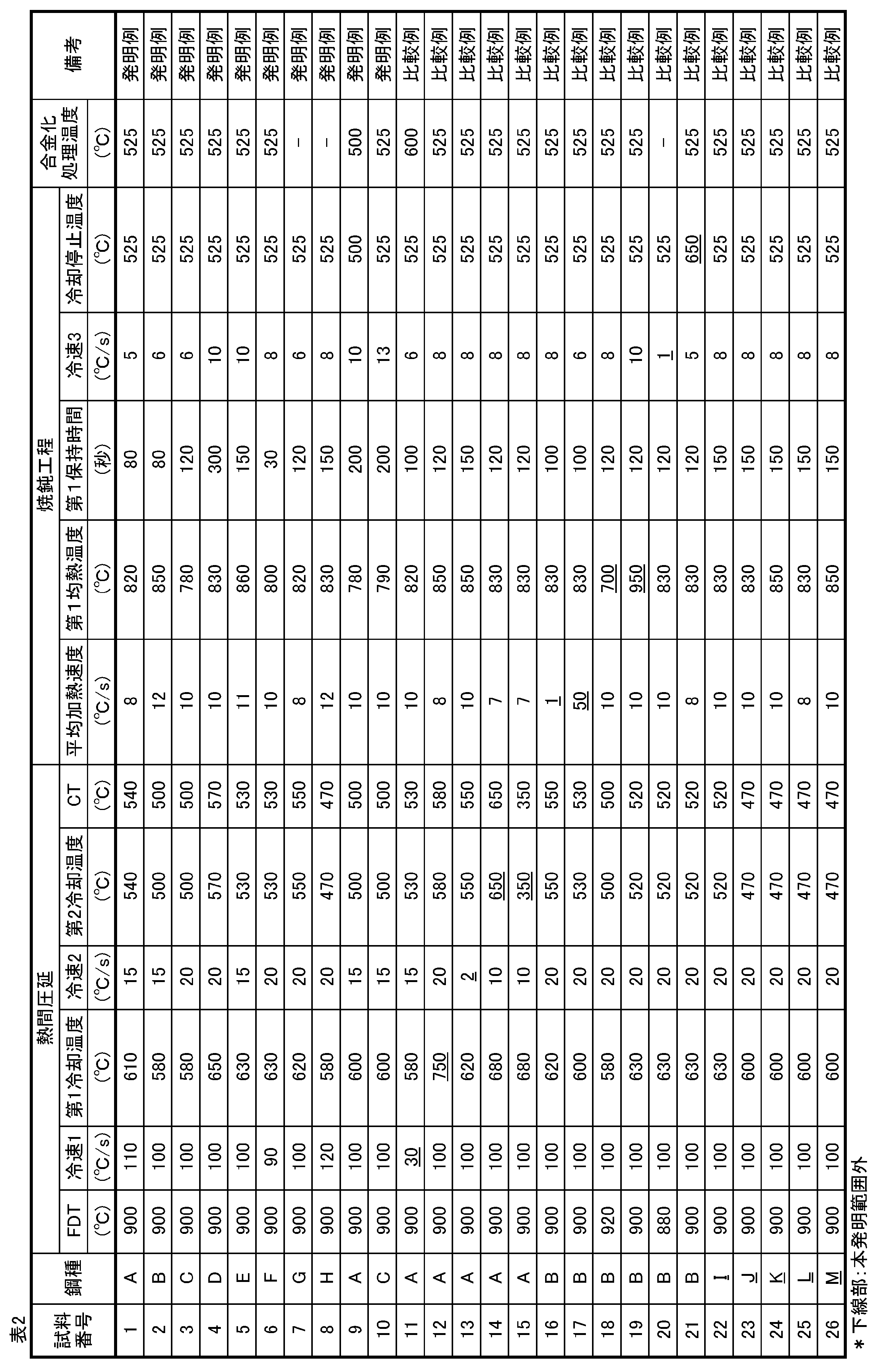
- the cold-rolled steel sheet thus obtained was subjected to an annealing treatment in accordance with the production conditions shown in Table 2 in a continuous hot dip galvanizing line, and after the hot dip galvanizing treatment, an alloying treatment was further performed at a temperature shown in Table 2.
- An alloyed hot-dip galvanized steel sheet (GA) was obtained.
- the plating treatment is as follows: zinc plating bath temperature: 460 ° C., zinc plating bath Al concentration: 0.14 mass% (when alloying treatment is performed), 0.18 mass% (when alloying treatment is not performed), plating adhesion per side The amount was 45 g / m 2 (double-sided plating).
- Some of the steel sheets were made of non-alloyed hot dip galvanized steel sheets (GI) without being alloyed by galvanization.
- a JIS No. 5 tensile test piece was taken from the manufactured steel sheet so that the direction perpendicular to the rolling direction was the longitudinal direction (tensile direction), and the tensile strength (TS) was measured by a tensile test (JIS Z2241 (1998)).
- TS tensile strength
- JIS Z2241 1998
- the obtained cold-rolled steel sheet was cut into 30 mm x 100 mm with the rolling direction as the longitudinal direction, and the end face was ground and the specimen was bent 180 ° with a curvature radius of 10 mm at the punch tip. gave.
- resistance welding spot welding
- spot welding was performed using a test piece cut into 50 ⁇ 150 mm with the direction perpendicular to the rolling direction of the obtained cold-rolled steel sheet as the longitudinal direction.
- Welding is performed by spot spot welding with the plate assembly tilted 4 ° using a servo motor pressurization type single phase direct current (50Hz) resistance welder attached to the welding gun. Carried out.
- the welding conditions were a pressure of 3.5 kN and a hold time of 0.36 seconds.
- the welding current and welding time were adjusted so that the nugget diameter was 5.9 mm.
- After welding cut the test piece in half and observe the cross-section with an optical microscope. Good resistance to resistance cracking of cracks with no cracks of 0.2 mm or more ( ⁇ ), cracks of 0.2 mm or more The resistance resistance cracking resistance was inferior (x).
- the volume fraction of ferrite, martensite, and non-recrystallized ferrite in the steel sheet is 2000 times using SEM (scanning electron microscope) after corroding the plate thickness section parallel to the rolling direction of the steel sheet and then corroding with 3vol% nital.
- the area ratio was measured by a point count method (according to ASTM E562-83 (1988)), and the area ratio was defined as the volume fraction.
- the average grain size of ferrite and martensite is calculated by taking the images of each ferrite and martensite crystal grains that have been identified in advance from steel sheet structure images using Media-Cybernetics Image-Pro. The circle equivalent diameter was calculated and the values were averaged.
- the volume fraction of retained austenite was determined by diffracting X-ray intensities on a 1/4 plane of the plate thickness after polishing the steel plate to 1/4 plane in the thickness direction.
- the X-ray diffraction method device: RINT2200 made by Rigaku
- the ⁇ 200 ⁇ plane, ⁇ 211 ⁇ plane, ⁇ 220 ⁇ plane of iron ferrite and austenite Measure the integrated intensity of X-ray diffraction lines on the ⁇ 200 ⁇ , ⁇ 220 ⁇ , and ⁇ 311 ⁇ planes of the X-ray diffraction handbook (2000)
- the volume fraction of retained austenite was obtained from the calculation formula described in p.26, 62-64.
- the average grain size of retained austenite was observed at a magnification of 5000 using EBSD (electron beam backscattering diffraction method), the equivalent circle diameter was calculated using Image-Pro, and the values were averaged. Asked. Further, the steel sheet structure was observed by SEM, TEM (transmission electron microscope), and FE-SEM (field emission scanning electron microscope), and bainite was observed to obtain the volume fraction in the same manner as described above. The average crystal grain size of bainite was also calculated by calculating the equivalent circle diameter from the steel sheet structure photograph using the above-mentioned Image-Pro and averaging these values.
- EBSD electron beam backscattering diffraction method
- the particle size of Ti or Nb-based precipitates is observed by using SEM and TEM at magnifications of 5000, 10000, and 20000, and using Image-Pro, the particle equivalent diameter is calculated by calculating the equivalent circle diameter. It was. The number of Ti or Nb-based precipitates was observed using SEM and TEM at magnifications of 5000, 10000, and 20000, and the average number of 10 locations was determined.
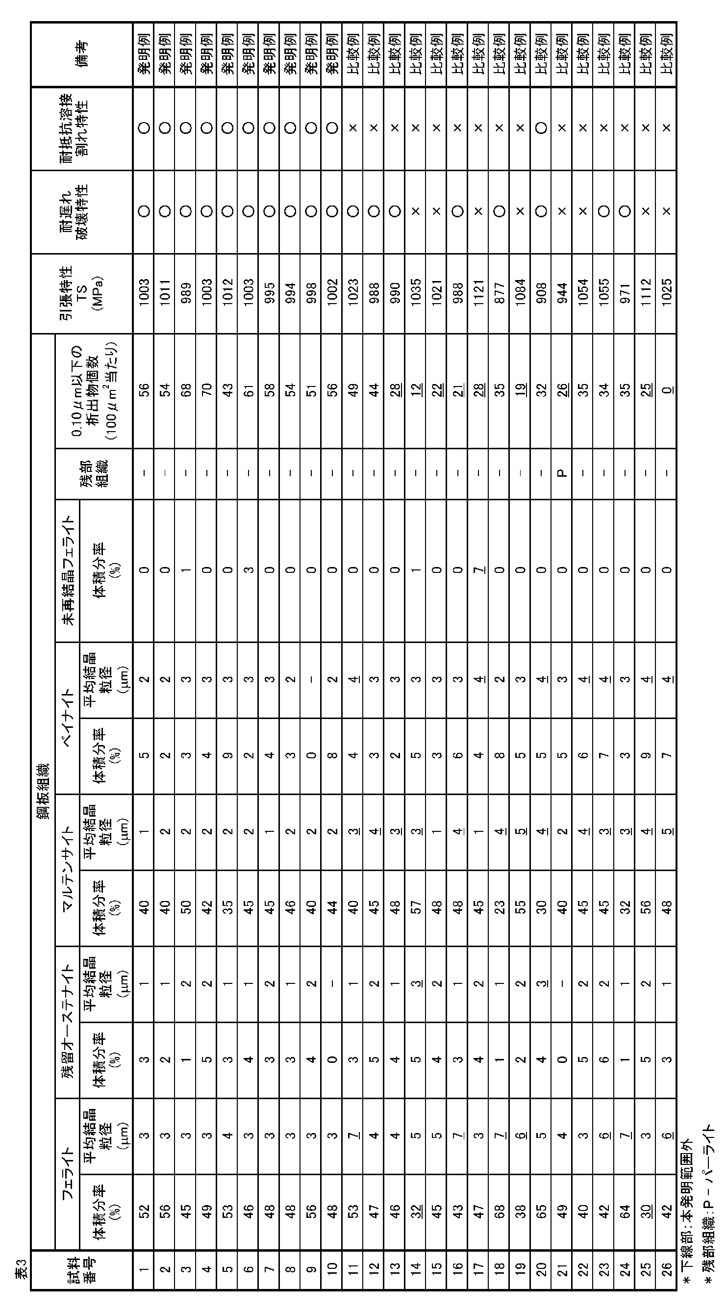
- Table 3 shows the measured tensile properties, delayed fracture resistance, resistance weld cracking characteristics, and steel sheet structure measurement results. From the results shown in Table 3, in all of the inventive examples, ferrite having an average crystal grain size of less than 5 ⁇ m is 35 to 70% in volume fraction, and residual austenite having an average crystal grain size of 2 ⁇ m or less is 12% or less in volume fraction. Martensite with an average particle size of 2 ⁇ m or less is 15 to 60% by volume, bainite with an average particle size of 3 ⁇ m or less is 30% or less, and unrecrystallized ferrite is 5% or less by volume.
Landscapes
- Chemical & Material Sciences (AREA)
- Engineering & Computer Science (AREA)
- Materials Engineering (AREA)
- Mechanical Engineering (AREA)
- Metallurgy (AREA)
- Organic Chemistry (AREA)
- Physics & Mathematics (AREA)
- Thermal Sciences (AREA)
- Crystallography & Structural Chemistry (AREA)
- Heat Treatment Of Sheet Steel (AREA)
Abstract
Description
また、特許文献2ではSi、Al、Mn添加量を制御することで、抵抗溶接時の表面割れを改善する技術が開示されている。
また、特許文献2に記載の技術では、980MPa以上の高強度を達成することは困難であり、優れた耐遅れ破壊特性を得ることも困難である。このように、980MPa以上のめっき鋼板において、耐遅れ破壊特性と耐抵抗溶接割れ特性の双方を両立して改善することは困難であり、めっき鋼板以外の鋼板を含めても、これらの特性を兼備する鋼板は開発されていないのが実情である。
本発明は、上記の新規な知見に基づきなされたもので、以下の構成を有する。
C:0.05%以上0.22%以下、
Si:0.05%以上1.80%以下、
Mn:1.45%以上3.35%以下、
P:0.05%以下、
S:0.005%以下、
Al:0.01%以上0.10%以下、
N:0.010%以下および
B:0.0002%以上0.0045%以下
を含有し、さらに、
Ti:0.005%以上0.090%以下およびNb:0.005%以上0.090%以下のうちから選ばれる1種以上を含有し、残部はFeおよび不可避的不純物である成分組成を有し、
フェライトを体積分率で35%以上70%以下、残留オーステナイトを体積分率で12%以下、マルテンサイトを体積分率で15%以上60%以下、残部としてベイナイトを体積分率で30%以下および未再結晶フェライトを体積分率で5%以下を含む組織を有し、
前記フェライトの平均結晶粒径が5μm以下、
前記残留オーステナイトの平均結晶粒径が2μm以下、
前記マルテンサイトの平均結晶粒径が2μm以下、
前記ベイナイトの平均結晶粒径が3μm以下であって、
前記組織が、平均粒径が0.10μm以下のTiまたはNb系析出物を100μm2当たり平均で30個以上を含有するめっき鋼板。
質量%で、
V:0.10%以下、
Cu:0.50%以下、
Ni:0.50%以下、
Mo:0.50%以下、
Cr:0.80%以下並びに
Caおよび/またはREM:0.0050%以下
のうちから選ばれる1種または2種以上を含有する、上記1に記載のめっき鋼板。
C:0.05%以上0.22%以下、
Si:0.05%以上1.80%以下、
Mn:1.45%以上3.35%以下、
P:0.05%以下、
S:0.005%以下、
Al:0.01%以上0.10%以下、
N:0.010%以下および
B:0.0002%以上0.0045%以下
を含有し、さらに、質量%で、
Ti:0.005%以上0.090%以下、Nb:0.005%以上0.090%以下のうちから選ばれる1種以上を含有し、残部はFeおよび不可避的不純物である成分組成を有する鋼スラブに、仕上げ圧延の終了温度850℃以上950℃以下の条件で熱間圧延を施して熱延鋼板とし、
該熱延鋼板を、75℃/s以上の第1平均冷却速度で680℃以下まで冷却し、5℃/s以上の第2平均冷却速度で400℃以上580℃以下の範囲まで冷却し、その後、巻取り、冷間圧延を施して冷延鋼板とし、
該冷延鋼板を、3~30℃/sの平均加熱速度で760℃以上900℃以下の温度域まで加熱し、760℃以上900℃以下の温度域で15秒以上保持して均熱した後、3~30℃/sの平均冷却速度で600℃以下の温度域まで冷却する焼鈍を施し、
該焼鈍後の冷延鋼板にめっき処理を施すめっき鋼板の製造方法。
質量%で、
V:0.10%以下、
Cu:0.50%以下、
Ni:0.50%以下、
Mo:0.50%以下、
Cr:0.80%以下並びに
Caおよび/またはREM:0.0050%以下
のうちから選ばれる1種または2種以上を含有する、上記3に記載のめっき鋼板の製造方法。
Cは鋼板の高強度化に有効な元素であり、本発明におけるベイナイト、マルテンサイトおよび残留オーステナイトの第2相(第1相であるフェライト以外の組織)形成に関しても寄与する。0.05%未満では、必要なベイナイト、マルテンサイトおよび残留オーステナイト体積率の確保が難しいため、強度確保が困難である。好ましくは0.06%以上である。さらに好ましくは0.065%以上である。一方、過剰に添加すると抵抗溶接後の硬度が高くなり、抵抗溶接時の靭性が低下して耐抵抗溶接割れ特性が劣化するため、その含有量は0.22%以下とする。好ましくは0.20%以下であり、さらに好ましくは0.18%以下である。
Siはフェライトを固溶強化し、高強度化に有効な元素である。その効果を得るためには0.05%以上の添加が必要である。好ましくは0.10%以上である。さらに好ましくは0.20%以上である。しかしながら、Siの過剰な添加はめっき性が低下して不めっきとなるため、その含有量は1.80%以下とする。好ましくは1.60%以下である。さらに好ましくは1.50%以下である。
Mnは固溶強化および第2相を生成することで高強度化に寄与する元素である。また、オーステナイトを安定化させる元素であり、第2相の分率制御に必要な元素である。その効果を得るためには1.45%以上含有することが必要である。好ましくは1.60%以上である。さらに好ましくは1.80%以上である。一方、過剰に含有した場合、第2相の体積率が過剰になる上に、水素が鋼板内に侵入した場合、粒界のすべり拘束が増加し、結晶粒界でのき裂が進展しやすくなるため耐遅れ破壊特性が低下する。そのため、含有量を3.35%以下とする。好ましくは3.20%以下である。さらに好ましくは3.0%以下である。
Pは固溶強化により高強度化に寄与するが、過剰に添加された場合には、粒界への偏析が著しくなって粒界を脆化させるため、耐抵抗溶接割れ特性が低下する。そのため、含有量を0.05%以下とする。好ましくは0.04%以下である。さらに好ましくは0.03%以下である。特に下限は無いが、極低P化は製鋼コストが上昇するため、0.0005%以上含有することが好ましい。さらに好ましくは0.0008%以上である。
Sの含有量が多い場合には、MnSなどの硫化物が多く生成し、水素侵入時にMnSからき裂が生成するために耐遅れ破壊特性が低下する。そのため、含有量の上限を0.005%とする。好ましくは、0.0045%以下である。さらに好ましくは0.004%以下である。特に下限は無いが、極低S化はPと同様に製鋼コストが上昇するため、0.0002%以上含有することが好ましい。さらに好ましくは0.0004%以上である。
Alは脱酸に必要な元素であり、この効果を得るためには0.01%以上含有することが必要である。好ましくは0.015%以上である。一方、0.10%を超えて含有しても効果が飽和するため、0.10%以下とする。好ましくは0.06%以下である。さらに好ましくは0.05%以下である。
Nは粗大な窒化物を形成して耐遅れ破壊特性を劣化させることから、含有量を抑える必要がある。特に、Nが0.010%超では、この傾向が顕著となることからNの含有量を0.010%以下とする。好ましくは0.008%以下である。さらに好ましくは0.006%以下である。
Bは焼入れ性を向上させ、第2相を生成することで高強度化に寄与し、焼入れ性を確保しつつ、マルテンサイト変態開始点を低下させない元素である。また粒界に偏析することで粒界強度を向上させるため、耐遅れ破壊特性に有効である。この効果を発揮するために、0.0002%以上含有させる。好ましくは0.0003%以上である。しかし、過剰な添加は靭性を劣化させるために耐抵抗溶接割れ特性を低下させるため、その含有量を0.0045%以下とする。好ましくは0.0035%以下である。さらに好ましくは0.0030%以下である。
Tiは微細な炭窒化物を形成することで、強度上昇に寄与することができる元素である。また、Tiの微細な炭窒化物は水素のトラップサイトとなり、かつ、結晶粒微細化に効果があるために、抵抗溶接割れの抑制にも有効である。このような効果を発揮させるためには、Tiの含有量の下限を0.005%とする。好ましい下限は0.008%である。さらに好ましい下限は0.010%である。一方、多量にTiを添加すると、延性が著しく低下するため、その含有量は0.090%以下とする。好ましくは0.080%以下である。さらに好ましくは0.070%以下である。
NbもTiと同様に微細な炭窒化物を形成することで、強度上昇に寄与するほかに水素のトラップサイトとなり、かつ、結晶粒微細化に効果がある。このような効果を発揮させるためには、Nbの含有量の下限を0.005%とする。好ましい下限は0.008%である。さらに好ましい下限は0.010%である。一方、多量にNbを添加すると、延性が著しく低下するだけでなく、再結晶速度を著しく低下させるために未再結晶フェライトが増加する。そのため、その含有量は0.090%以下とする。好ましくは0.080%以下である。さらに好ましくは0.070%以下である。
Vは微細な炭窒化物を形成することで、強度上昇に寄与することができる。このような作用を有するために、Vを0.01%以上含有させることが好ましい。さらに好ましくは0.02%以上である。一方、多量のVを添加させても、0.10%を超えた分の強度上昇効果は小さく、そのうえ、合金コストの増加も招いてしまう。したがって、Vの含有量は0.10%以下が好ましい。さらに好ましくは0.08%以下である。
Cuは固溶強化により高強度化に寄与して、また第2相を生成することで高強度化に寄与する元素であり、必要に応じて添加することができる。このような効果を発揮させるためには0.05%以上含有させることが好ましい。さらに好ましくは0.08%以上である。一方、0.50%超含有させても効果が飽和し、またCuに起因する表面欠陥が発生しやすくなるため、その含有量は0.50%以下が好ましい。さらに好ましくは0.35%以下である。
NiもCuと同様、固溶強化により高強度化に寄与して、また第2相を生成することで高強度化に寄与する元素であり、必要に応じて添加することができる。このような効果を発揮させるためには0.05%以上含有させることが好ましい。さらに好ましくは0.08%以上である。また、Cuと同時に添加すると、Cu起因の表面欠陥を抑制する効果があるため、Cu添加時に有効である。一方、0.50%超含有させても効果が飽和するため、その含有量は0.50%以下が好ましい。さらに好ましくは0.35%以下である。
Moは第2相を生成することで高強度化に寄与し、さらに一部炭化物を生成して高強度化に寄与する元素であり、必要に応じて添加することができる。このような効果を発揮させるためには、0.05%以上含有させることが好ましい。さらに好ましくは0.08%以上である。一方、0.50%超含有させても効果が飽和するため、その含有量は0.50%以下が好ましい。さらに好ましくは0.35%以下である。
Crは第2相を生成することで高強度化に寄与する元素であり、必要に応じて添加することができる。このような効果を発揮させるためには、0.10%以上含有させることが好ましい。さらに好ましくは0.13%以上である。一方、0.80%超含有させると、溶融亜鉛めっき性が低下するために不めっきとなるため、その含有量は0.80%以下とする。さらに好ましく0.70%以下である。
CaおよびREM(希土類元素)は、硫化物の形状を球状化して耐遅れ破壊特性への悪影響の改善に寄与する元素であり、必要に応じて添加することができる。このような効果を発揮するためには0.0005%以上含有させることが好ましい。さらに好ましくは0.0008%以上である。一方、0.0050%超含有させても効果が飽和するため、その含有量を0.0050%以下とする。さらに好ましくは0.0035%以下である。
フェライトの体積分率が70%超では、引張強さ980MPa以上を達成することが困難である。よって、フェライトの体積分率は70%以下とする。好ましくは65%以下であり、さらに好ましくは60%以下である。また、体積分率が35%未満では転位密度の高い第2相が多くなるため、耐遅れ破壊特性が劣化する。そのため、フェライトの体積分率は35%以上とする。伸びを向上させるため、好ましくは40%以上とする。
フェライトの平均結晶粒径が5μm超では、抵抗溶接時に結晶粒がさらに粗大化することで靭性が劣化し内割れが生じる。そのため、フェライトの結晶粒径は5μm以下とする。好ましくは4μm以下とする。伸びを向上させるため、好ましくは0.5μm以上とする。
残留オーステナイトは加工誘起マルテンサイト変態することで強度に寄与する。また、水素トラップサイトとなるため、耐遅れ破壊特性に対しても有効である。しかしながら、マルテンサイト変態してしまうと高い転位密度を保有するために、水素侵入によりき裂が生成し、耐遅れ破壊特性に関しては劣位となってしまう。そのため、残留オーステナイトの体積分率は12%以下とする。好ましくは0%超10%以下である。さらに好ましくは1%以上である。さらに好ましくは7%以下である。なお、残留オーステナイトの体積分率は0%であってもよい。
残留オーステナイトの平均結晶粒径は、残留オーステナイト内のC分布の影響で、プレス成形時にマルテンサイトが生成しやすくなり、耐遅れ破壊特性が低下するため、その上限は2μmとする。下限は特に規定はしないが0.3μm以上であると伸びに及ぼす寄与が大きくなるため、0.3μm以上が好ましい。
所望の強度を確保するためには、マルテンサイトの体積分率は15%以上とする。好ましくは20%以上である。さらに好ましくは23%以上である。一方で、マルテンサイトの体積分率が60%超では、水素侵入時にき裂生成が発生しやすいだけでなく、き裂進展速度も増加するため、その上限は60%とする。好ましくは57%以下とする。さらに好ましくは55%以下とする。
マルテンサイトの平均粒径が2μm超では、抵抗溶接時に結晶粒がさらに粗大化することで靭性が劣化し、内割れが生じる。そのため、マルテンサイトの平均結晶粒径は2μm以下とする。好ましくは1.8μm以下とする。なお、ここでいうマルテンサイトとは、焼鈍後に生成するマルテンサイトを指すが、焼鈍の冷却時にマルテンサイト変態した、自己焼戻し(オートテンパー)マルテンサイト、マルテンサイト変態した後に焼戻し処理された焼戻しマルテンサイト、および焼戻しされずにオーステナイトからマルテンサイト変態したフレッシュマルテンサイトを含む。
ベイナイトは高強度化に寄与するが、高い転位密度を含むため、体積分率が30%超では、耐遅れ破壊特性が劣化する。そのため、上限は30%とする。好ましくは0%超25%以下である。さらに好ましくは5%以上である。さらに好ましくは20%以下である。なお、ベイナイトの体積分率は0%であってもよい。
ベイナイトの平均粒径が3μm超では、抵抗溶接時に結晶粒がさらに粗大化することで靭性が劣化し内割れが生じるため、ベイナイトの平均結晶粒径は3μm以下とする。好ましくは2.5μm以下とする。
また、未再結晶フェライトも高強度化に寄与するが、ベイナイト同様に高い転位密度を含むため、その上限は5%である。好ましくは0%超3%以下である。さらに好ましくは1%以下である。なお、未再結晶フェライトの体積分率は0%であってもよい。
本発明では、平均粒径が0.10μm以下のTiまたはNb系析出物を100μm2辺り平均で30個以上を含有させる必要がある。これは、TiまたはNb系析出物が水素のトラップサイトになって耐遅れ破壊特性を向上させる上に、結晶粒微細化に効果的であり、耐抵抗溶接割れ特性を向上させるためである。粒径が0.10μm超、もしくは上記析出物が100μm2当たり平均で30個未満であると、耐遅れ破壊特性および耐抵抗溶接割れ特性が低下する。好ましくは100μm2当たり50個以上である。さらに好ましくは100μm2当たり60個以上である。TiまたはNb系析出物としては、具体的には、炭化物が挙げられる。
上記成分組成(化学成分)を有する鋼スラブを、仕上げ圧延の終了温度850℃以上950℃以下の条件で熱間圧延を行い、1次冷却として75℃/s以上の第1平均冷却速度で680℃以下まで冷却した後、2次冷却として5℃/s以上の第2平均冷却速度で400℃以上580℃以下の範囲で冷却した後に巻取り、その熱延鋼板に酸洗を施した後、引き続き冷間圧延を行い、次いで焼鈍工程では、冷延鋼板を、3~30℃/sの平均加熱速度で760℃以上900℃以下の温度域まで加熱し、第1均熱温度として760℃以上900℃以下の温度域で15秒以上保持した後、3~30℃/sの平均冷却速度で600℃以下の温度域まで冷却して焼鈍後、溶融亜鉛めっき処理を施し、室温まで冷却する。
・仕上げ圧延終了温度:850℃以上950℃以下
熱間圧延は、鋼板内の組織均一化、材質の異方性低減により、焼鈍後の耐遅れ破壊特性、耐抵抗溶接割れ特性を向上させるため、オーステナイト単相域にて終了する必要がある。そのため、仕上げ圧延終了温度は850℃以上とする。一方、仕上げ圧延終了温度が950℃を超えると、熱延組織が粗大になり、焼鈍後の結晶粒も粗大化する。そのため、仕上げ圧延終了温度は850℃以上950℃以下とする。
1次冷却として75℃/s以上の第1平均冷却速度で680℃以下まで冷却した後、2次冷却として5℃/s以上の第2平均冷却速度で400℃以上580℃以下の範囲まで冷却
本発明では、熱間圧延時にTiもしくはNbの析出物の析出形態を制御することで、焼鈍後の鋼板組織を制御するため、仕上げ圧延後の冷却は重要な工程である。熱間圧延終了後、冷却過程でオーステナイトがフェライト変態するが、高温ではそのフェライトが粗大化する。そのため、熱間圧延終了後に鋼板を急冷することで、組織をできるだけ均質化すると同時に、析出物生成を抑制する。そのため、1次冷却として75℃/s以上の第1平均冷却速度で680℃以下まで冷却する。
1次冷却で冷却する温度が680℃を超えると、熱延鋼板の鋼板組織におけるパーライトが過剰に生成し、鋼板組織が不均質となるため、耐抵抗溶接割れ特性が低下する。また、マルテンサイトについて、所望の平均結晶粒径が得られない。好ましくは650℃以下とする。また、熱延鋼板の鋼板組織にマルテンサイトが過剰に増加するため、好ましくは400℃以上とする。
巻取り温度が580℃超では、熱延鋼板の鋼板組織におけるフェライトおよびパーライトが過剰に生成する。また、残留オーステナイトについて、所望の平均結晶粒径が得られず、平均結晶粒径が0.10μm以下のTiまたはNb系析出物を100μm2当たり平均で30個以上も得られない。そのため、巻取り温度の上限は580℃とすることが好ましい。より好ましくは550℃以下である。また、巻取り温度が400℃未満ではTiおよびNbの析出物が充分に析出せずに固溶した状態となるため、焼鈍後の微細化への効果が期待できない。また、平均結晶粒径が0.10μm以下のTiまたはNb系析出物を100μm2当たり平均で30個以上が得られない。そのため、巻取り温度は400℃以上とすることが好ましい。より好ましくは420℃以上とする。
熱間圧延工程後、酸洗工程を実施し、熱延板表層のスケールを除去するのが好ましい。酸洗工程は特に限定されず、常法に従って実施すればよい。
所定の板厚の冷延板に圧延する冷間圧延工程を行う。冷間圧延工程は特に限定されず常法で実施すればよい。冷間圧延における圧下率の好ましい範囲は、30%以上95%以下である。
焼鈍工程においては、再結晶を進行させるとともに、高強度化のため鋼板組織に微細なベイナイト、残留オーステナイトやマルテンサイトを形成するために実施する。そのため、焼鈍工程では、3~30℃/sの平均加熱速度で760℃以上900℃以下の温度域まで加熱し、均熱温度として760℃以上900℃以下の温度域で15秒以上保持した後、3~30℃/sの平均冷却速度で600℃以下の温度域まで冷却する。
なお、焼鈍後に調質圧延を実施しても良い。伸長率の好ましい範囲は0.05%~2.0%である。
平均加熱速度を3~30℃/sとすることで、焼鈍後の結晶粒を微細化させることが可能となる。急速に加熱すると再結晶が進行しにくくなる。また、ベイナイトについて所望の平均結晶粒径が得られず、未再結晶フェライトについての所望の体積分率、および平均結晶粒径が0.10μm以下のTiまたはNb系析出物を100μm2当たり平均で30個以上得られない。そのため、平均加熱速度の上限は30℃/sとする。未再結晶フェライトが増加するため、好ましくは25℃/s以下とする。
また、加熱速度が小さすぎるとフェライトやマルテンサイト粒が粗大化して所定の平均粒径が得られない。また、平均結晶粒径が0.10μm以下のTiまたはNb系析出物を100μm2当たり平均で30個以上得られない。そのため、3℃/s以上の平均加熱速度が必要である。好ましくは5℃/s以上である。
均熱温度としては、フェライトとオーステナイトの2相域もしくはオーステナイト単相域である温度域で均熱する。760℃未満ではフェライト分率が多くなるため、強度確保が困難になる。また、フェライトおよびマルテンサイトについて、所望の平均結晶粒径が得られない。そのため、均熱温度の下限は760℃とする。好ましくは780℃以上とする。均熱温度が高すぎると、フェライト、マルテンサイトおよびオーステナイトの結晶粒成長が顕著となり、結晶粒が粗大化することで耐抵抗溶接割れ特性が低下する。また、平均結晶粒径が0.10μm以下のTiまたはNb系析出物を100μm2当たり平均で30個以上得られない。そのため、均熱温度の上限は900℃とする。好ましくは880℃以下である。
上記の均熱温度において、再結晶の進行および一部もしくは全てについてオーステナイト変態させるため、均熱時間は15秒以上の保持が必要である。未再結晶フェライトの体積率が増加するため、好ましくは20秒以上とする。上限は特に限定されないが、600秒以内が好ましい。
上記の均熱後は、均熱温度から600℃以下の温度域(冷却停止温度)まで、3~30℃/sの平均冷却速度で冷却する必要がある。平均冷却速度が3℃/s未満では、冷却中にフェライト変態が進行して、第2相の体積分率が減少するため、強度確保が困難である。また、マルテンサイト、残留オーステナイト、およびベイナイトについて、所望の平均結晶粒径が得られない。一方、平均冷却速度が30℃/sを超える場合には、マルテンサイトが過剰に生成するだけでなく、設備上これを実現することが困難でもある。また、冷却停止温度が600℃を超える場合には、パーライトが過剰に生成するため、鋼板のミクロ組織における所定の体積分率を得られず、強度確保が困難である。また、平均結晶粒径が0.10μm以下のTiまたはNb系析出物を100μm2当たり平均で30個以上得られず、耐遅れ破壊特性および耐抵抗溶接割れ特性が低下する。なお、上記の平均冷却速度は、600℃以下の、めっき浴へ浸漬するまでの範囲における冷却速度の平均であり、この温度領域において3~30℃/sの平均冷却速度が維持されればよい。
上記焼鈍後にめっき処理を施し、室温まで冷却する。めっき処理には、溶融亜鉛めっき処理、電気亜鉛めっき処理などがある。めっき浴に浸漬する鋼板温度は、例えば、溶融亜鉛めっき処理の場合、(溶融亜鉛めっき浴温度-40)℃~(溶融亜鉛めっき浴温度+50)℃とすることが好ましい。めっき浴に浸漬する鋼板温度が(溶融亜鉛めっき浴温度-40)℃を下回ると、鋼板がめっき浴に浸漬される際に、溶融亜鉛の一部が凝固してしまい、めっき外観を劣化させる場合がある。そのため、下限を(溶融亜鉛めっき浴温度-40)℃とする。また、めっき浴に浸漬する鋼板温度が(溶融亜鉛めっき浴温度+50)℃を超えると、めっき浴の温度が上昇するため、量産性に問題が生じる。その他の条件については、通常のめっき処理で行われている条件を使用することができる。
上記めっき後は、450℃以上600℃以下の温度域でめっきを合金化処理することができる。450℃以上600℃以下の温度域で合金化処理することにより、めっき中のFe濃度は7~15質量%になり、めっきの密着性や塗装後の耐食性が向上する。450℃未満では、合金化が十分に進行せず、犠牲防食作用の低下や摺動性の低下を招き、600℃より高い温度では、合金化の進行が過度となり、耐パウダリング性が低下する。
以下、本発明の実施例を説明する。
ただし、本発明は、もとより下記実施例によって制限を受けるものではなく、本発明の趣旨に適合し得る範囲で適宜変更を加えて実施することも可能であり、それらはいずれも本発明の技術的範囲に含まれる。
表1に示す成分組成の鋼を溶製して鋳造してスラブを製造し、熱間圧延加熱温度を1250℃、仕上げ圧延の終了温度(FDT)を表2に示す条件で熱間圧延を行い、板厚:3.2mmの熱延鋼板とした後、表2で示す第1平均冷却速度(冷速1)で第1冷却温度まで冷却した後、第2平均冷却速度(冷速2)で第2冷却温度まで冷却し、巻取り温度(CT)で巻取った。ついで、得られた熱延板を酸洗した後、冷間圧延を施し、冷延板(板厚:1.4mm)を製造した。
遅れ破壊試験に関しては、得られた冷延鋼板の圧延方向を長手として30mm×100mmに切断し、端面を研削加工した試験片を用い、試験片をポンチ先端の曲率半径10mmで180°曲げ加工を施した。この曲げ加工を施した試験片に生じたスプリングバックをボルトにより内側間隔が20mmになるように締込み、試験片に応力を負荷したのち、20℃、pH=1.5の塩酸に浸漬し、破壊が生じるまでの時間を最長100時間まで測定した。100時間以内に試験片にき裂が生じないものを良好(○)とし、試験片にき裂が発生した場合は劣(×)とした。
また、SEM、TEM(透過型電子顕微鏡)、FE-SEM(電界放出形走査電子顕微鏡)により、鋼板組織を観察し、ベイナイトを観察して上記と同様に体積分率を求めた。ベイナイトの平均結晶粒径についても、上述のImage-Proを用いて、鋼板組織写真から円相当直径を算出し、それらの値を平均して求めた。
表3に示す結果から、本発明例は何れも平均結晶粒径が5μm未満のフェライトを体積分率で35~70%、平均結晶粒径が2μm以下の残留オーステナイトを体積分率で12%以下、平均粒径が2μm以下のマルテンサイトを体積分率で15~60%、平均粒径が3μm以下のベイナイトを体積分率で30%以下、未再結晶フェライトを体積分率で5%以下を含む複合組織を有し、その結果、980MPa以上の引張強さが得られ、遅れ破壊特性評価試験において100時間破壊が生じておらず優れた耐遅れ破壊特性を有し、かつ、抵抗溶接後も内割れが生じず、優れた耐抵抗溶接割れを得ることが確認された。
Claims (5)
- 質量%で、
C:0.05%以上0.22%以下、
Si:0.05%以上1.80%以下、
Mn:1.45%以上3.35%以下、
P:0.05%以下、
S:0.005%以下、
Al:0.01%以上0.10%以下、
N:0.010%以下および
B:0.0002%以上0.0045%以下
を含有し、さらに、
Ti:0.005%以上0.090%以下およびNb:0.005%以上0.090%以下のうちから選ばれる1種以上を含有し、残部はFeおよび不可避的不純物である成分組成を有し、
フェライトを体積分率で35%以上70%以下、残留オーステナイトを体積分率で12%以下、マルテンサイトを体積分率で15%以上60%以下、残部としてベイナイトを体積分率で30%以下および未再結晶フェライトを体積分率で5%以下を含む組織を有し、
前記フェライトの平均結晶粒径が5μm以下、
前記残留オーステナイトの平均結晶粒径が2μm以下、
前記マルテンサイトの平均結晶粒径が2μm以下、
前記ベイナイトの平均結晶粒径が3μm以下であって、
前記組織が、平均粒径が0.10μm以下のTiまたはNb系析出物を100μm2当たり平均で30個以上を含有するめっき鋼板。 - 前記成分組成は、さらに、
質量%で、
V:0.10%以下、
Cu:0.50%以下、
Ni:0.50%以下、
Mo:0.50%以下、
Cr:0.80%以下並びに
Caおよび/またはREM:0.0050%以下
のうちから選ばれる1種または2種以上を含有する、請求項1に記載のめっき鋼板。 - 質量%で、
C:0.05%以上0.22%以下、
Si:0.05%以上1.80%以下、
Mn:1.45%以上3.35%以下、
P:0.05%以下、
S:0.005%以下、
Al:0.01%以上0.10%以下、
N:0.010%以下および
B:0.0002%以上0.0045%以下
を含有し、さらに、質量%で、
Ti:0.005%以上0.090%以下、Nb:0.005%以上0.090%以下のうちから選ばれる1種以上を含有し、残部はFeおよび不可避的不純物である成分組成を有する鋼スラブに、仕上げ圧延の終了温度850℃以上950℃以下の条件で熱間圧延を施して熱延鋼板とし、
該熱延鋼板を、75℃/s以上の第1平均冷却速度で680℃以下まで冷却し、5℃/s以上の第2平均冷却速度で400℃以上580℃以下の範囲まで冷却し、その後、巻取り、冷間圧延を施して冷延鋼板とし、
該冷延鋼板を、3~30℃/sの平均加熱速度で760℃以上900℃以下の温度域まで加熱し、760℃以上900℃以下の温度域で15秒以上保持して均熱した後、3~30℃/sの平均冷却速度で600℃以下の温度域まで冷却する焼鈍を施し、
該焼鈍後の冷延鋼板にめっき処理を施すめっき鋼板の製造方法。 - 前記成分組成は、さらに、
質量%で、
V:0.10%以下、
Cu:0.50%以下、
Ni:0.50%以下、
Mo:0.50%以下、
Cr:0.80%以下並びに
Caおよび/またはREM:0.0050%以下
のうちから選ばれる1種または2種以上を含有する、請求項3に記載のめっき鋼板の製造方法。 - 前記めっき処理を施した後に、450℃以上600℃以下の温度域で、めっきの合金化処理を施す、請求項3または請求項4に記載のめっき鋼板の製造方法。
Priority Applications (4)
| Application Number | Priority Date | Filing Date | Title |
|---|---|---|---|
| JP2017544984A JP6424967B2 (ja) | 2016-05-25 | 2017-05-11 | めっき鋼板およびその製造方法 |
| CN201780029820.5A CN109154045B (zh) | 2016-05-25 | 2017-05-11 | 镀覆钢板及其制造方法 |
| MX2018014261A MX2018014261A (es) | 2016-05-25 | 2017-05-11 | Lamina de acero recubierta o chapada y metodo para producir la misma. |
| KR1020187033519A KR102145293B1 (ko) | 2016-05-25 | 2017-05-11 | 도금 강판 및 그의 제조 방법 |
Applications Claiming Priority (2)
| Application Number | Priority Date | Filing Date | Title |
|---|---|---|---|
| JP2016104262 | 2016-05-25 | ||
| JP2016-104262 | 2016-05-25 |
Publications (1)
| Publication Number | Publication Date |
|---|---|
| WO2017203994A1 true WO2017203994A1 (ja) | 2017-11-30 |
Family
ID=60411176
Family Applications (1)
| Application Number | Title | Priority Date | Filing Date |
|---|---|---|---|
| PCT/JP2017/017912 Ceased WO2017203994A1 (ja) | 2016-05-25 | 2017-05-11 | めっき鋼板およびその製造方法 |
Country Status (5)
| Country | Link |
|---|---|
| JP (1) | JP6424967B2 (ja) |
| KR (1) | KR102145293B1 (ja) |
| CN (1) | CN109154045B (ja) |
| MX (1) | MX2018014261A (ja) |
| WO (1) | WO2017203994A1 (ja) |
Cited By (8)
| Publication number | Priority date | Publication date | Assignee | Title |
|---|---|---|---|---|
| WO2020145108A1 (ja) * | 2019-01-09 | 2020-07-16 | Jfeスチール株式会社 | 高強度冷延鋼板及びその製造方法 |
| JP2022520485A (ja) * | 2019-02-18 | 2022-03-30 | タタ、スティール、アイモイデン、ベスローテン、フェンノートシャップ | 機械的特性が改善された高強度鋼 |
| US11326226B2 (en) | 2020-09-01 | 2022-05-10 | Hyundai Steel Company | Material for hot stamping and method for manufacturing the same |
| US20220275471A1 (en) * | 2019-08-06 | 2022-09-01 | Jfe Steel Corporation | High-strength thin steel sheet and method for manufacturing same |
| CN115244201A (zh) * | 2020-05-08 | 2022-10-25 | 日本制铁株式会社 | 热轧钢板及其制造方法 |
| JP2023538652A (ja) * | 2020-09-01 | 2023-09-08 | ヒュンダイ スチール カンパニー | ホットスタンピング用素材及びその製造方法 |
| JP2023540210A (ja) * | 2020-09-01 | 2023-09-22 | ヒュンダイ スチール カンパニー | ホットスタンピング用素材及びその製造方法 |
| US11898218B2 (en) | 2020-09-01 | 2024-02-13 | Hyundai Steel Company | Material for hot stamping and method for manufacturing the same |
Families Citing this family (7)
| Publication number | Priority date | Publication date | Assignee | Title |
|---|---|---|---|---|
| KR101858853B1 (ko) * | 2016-12-19 | 2018-06-28 | 주식회사 포스코 | 용접성이 우수한 전봉강관용 열연강판 및 이의 제조방법 |
| CN110029271B (zh) * | 2019-04-09 | 2020-02-07 | 东北大学 | 一种500MPa级含铌螺纹钢筋及其制造方法 |
| CN110157864A (zh) * | 2019-05-21 | 2019-08-23 | 武汉钢铁有限公司 | 一种1300MPa级低氢致延迟开裂敏感性热成形钢及生产方法 |
| WO2021020439A1 (ja) * | 2019-07-31 | 2021-02-04 | Jfeスチール株式会社 | 高強度鋼板、高強度部材及びそれらの製造方法 |
| KR102411174B1 (ko) * | 2020-12-09 | 2022-06-22 | 현대제철 주식회사 | 핫 스탬핑 부품 |
| KR102865564B1 (ko) * | 2020-12-25 | 2025-09-29 | 제이에프이 스틸 가부시키가이샤 | 강판, 부재 및 그것들의 제조 방법 |
| KR20230088118A (ko) * | 2021-12-10 | 2023-06-19 | 현대제철 주식회사 | 핫스탬핑용 소재 |
Citations (8)
| Publication number | Priority date | Publication date | Assignee | Title |
|---|---|---|---|---|
| JP2010037652A (ja) * | 2008-07-11 | 2010-02-18 | Kobe Steel Ltd | 耐水素脆化特性および加工性に優れた高強度冷延鋼板 |
| JP2012012703A (ja) * | 2010-05-31 | 2012-01-19 | Jfe Steel Corp | 曲げ性および溶接性に優れる高強度溶融亜鉛めっき鋼板およびその製造方法 |
| JP2013044022A (ja) * | 2011-08-24 | 2013-03-04 | Nippon Steel & Sumitomo Metal Corp | 溶融亜鉛めっき鋼板およびその製造方法 |
| US20130136950A1 (en) * | 2007-10-10 | 2013-05-30 | Nucor Corporation | Complex metallographic structured high strength steel and method of manufacturing |
| JP2015034326A (ja) * | 2013-08-09 | 2015-02-19 | Jfeスチール株式会社 | 高降伏比高強度冷延鋼板およびその製造方法 |
| WO2015151427A1 (ja) * | 2014-03-31 | 2015-10-08 | Jfeスチール株式会社 | 高降伏比高強度冷延鋼板およびその製造方法 |
| WO2015151428A1 (ja) * | 2014-03-31 | 2015-10-08 | Jfeスチール株式会社 | 材質均一性に優れた高強度冷延鋼板およびその製造方法 |
| WO2015151419A1 (ja) * | 2014-03-31 | 2015-10-08 | Jfeスチール株式会社 | 高降伏比高強度冷延鋼板及びその製造方法 |
Family Cites Families (5)
| Publication number | Priority date | Publication date | Assignee | Title |
|---|---|---|---|---|
| JPS4949536B1 (ja) | 1969-02-13 | 1974-12-27 | ||
| JP3758515B2 (ja) | 2001-04-03 | 2006-03-22 | 住友金属工業株式会社 | 抵抗溶接性に優れた高張力亜鉛めっき鋼板 |
| JP5082451B2 (ja) * | 2006-01-24 | 2012-11-28 | Jfeスチール株式会社 | 深絞り性と延性に優れた高強度冷延鋼板の製造方法、およびその冷延鋼板を用いた高強度溶融亜鉛めっき鋼板の製造方法 |
| KR20100096840A (ko) * | 2009-02-25 | 2010-09-02 | 현대제철 주식회사 | 내지연파괴특성이 우수한 초고강도 용융아연도금강판 및 그제조방법 |
| JP5709151B2 (ja) * | 2009-03-10 | 2015-04-30 | Jfeスチール株式会社 | 成形性に優れた高強度溶融亜鉛めっき鋼板およびその製造方法 |
-
2017
- 2017-05-11 JP JP2017544984A patent/JP6424967B2/ja active Active
- 2017-05-11 WO PCT/JP2017/017912 patent/WO2017203994A1/ja not_active Ceased
- 2017-05-11 MX MX2018014261A patent/MX2018014261A/es unknown
- 2017-05-11 KR KR1020187033519A patent/KR102145293B1/ko active Active
- 2017-05-11 CN CN201780029820.5A patent/CN109154045B/zh active Active
Patent Citations (8)
| Publication number | Priority date | Publication date | Assignee | Title |
|---|---|---|---|---|
| US20130136950A1 (en) * | 2007-10-10 | 2013-05-30 | Nucor Corporation | Complex metallographic structured high strength steel and method of manufacturing |
| JP2010037652A (ja) * | 2008-07-11 | 2010-02-18 | Kobe Steel Ltd | 耐水素脆化特性および加工性に優れた高強度冷延鋼板 |
| JP2012012703A (ja) * | 2010-05-31 | 2012-01-19 | Jfe Steel Corp | 曲げ性および溶接性に優れる高強度溶融亜鉛めっき鋼板およびその製造方法 |
| JP2013044022A (ja) * | 2011-08-24 | 2013-03-04 | Nippon Steel & Sumitomo Metal Corp | 溶融亜鉛めっき鋼板およびその製造方法 |
| JP2015034326A (ja) * | 2013-08-09 | 2015-02-19 | Jfeスチール株式会社 | 高降伏比高強度冷延鋼板およびその製造方法 |
| WO2015151427A1 (ja) * | 2014-03-31 | 2015-10-08 | Jfeスチール株式会社 | 高降伏比高強度冷延鋼板およびその製造方法 |
| WO2015151428A1 (ja) * | 2014-03-31 | 2015-10-08 | Jfeスチール株式会社 | 材質均一性に優れた高強度冷延鋼板およびその製造方法 |
| WO2015151419A1 (ja) * | 2014-03-31 | 2015-10-08 | Jfeスチール株式会社 | 高降伏比高強度冷延鋼板及びその製造方法 |
Cited By (15)
| Publication number | Priority date | Publication date | Assignee | Title |
|---|---|---|---|---|
| JPWO2020145108A1 (ja) * | 2019-01-09 | 2021-02-18 | Jfeスチール株式会社 | 高強度冷延鋼板及びその製造方法 |
| WO2020145108A1 (ja) * | 2019-01-09 | 2020-07-16 | Jfeスチール株式会社 | 高強度冷延鋼板及びその製造方法 |
| US12241137B2 (en) | 2019-01-09 | 2025-03-04 | Jfe Steel Corporation | High-strength cold-rolled steel sheet and production method for same |
| JP2022520485A (ja) * | 2019-02-18 | 2022-03-30 | タタ、スティール、アイモイデン、ベスローテン、フェンノートシャップ | 機械的特性が改善された高強度鋼 |
| US12195819B2 (en) * | 2019-08-06 | 2025-01-14 | Jfe Steel Corporation | High-strength thin steel sheet and method for manufacturing same |
| US20220275471A1 (en) * | 2019-08-06 | 2022-09-01 | Jfe Steel Corporation | High-strength thin steel sheet and method for manufacturing same |
| CN115244201A (zh) * | 2020-05-08 | 2022-10-25 | 日本制铁株式会社 | 热轧钢板及其制造方法 |
| CN115244201B (zh) * | 2020-05-08 | 2023-05-12 | 日本制铁株式会社 | 热轧钢板及其制造方法 |
| US11326226B2 (en) | 2020-09-01 | 2022-05-10 | Hyundai Steel Company | Material for hot stamping and method for manufacturing the same |
| US11898218B2 (en) | 2020-09-01 | 2024-02-13 | Hyundai Steel Company | Material for hot stamping and method for manufacturing the same |
| JP2023540210A (ja) * | 2020-09-01 | 2023-09-22 | ヒュンダイ スチール カンパニー | ホットスタンピング用素材及びその製造方法 |
| JP2023538652A (ja) * | 2020-09-01 | 2023-09-08 | ヒュンダイ スチール カンパニー | ホットスタンピング用素材及びその製造方法 |
| JP7684385B2 (ja) | 2020-09-01 | 2025-05-27 | ヒュンダイ スチール カンパニー | ホットスタンピング用素材及びその製造方法 |
| US12312652B2 (en) | 2020-09-01 | 2025-05-27 | Hyundai Steel Company | Material for hot stamping and method of manufacturing the same |
| JP7684386B2 (ja) | 2020-09-01 | 2025-05-27 | ヒュンダイ スチール カンパニー | ホットスタンピング用素材及びその製造方法 |
Also Published As
| Publication number | Publication date |
|---|---|
| CN109154045B (zh) | 2020-10-09 |
| JPWO2017203994A1 (ja) | 2018-06-14 |
| CN109154045A (zh) | 2019-01-04 |
| JP6424967B2 (ja) | 2018-11-21 |
| KR102145293B1 (ko) | 2020-08-18 |
| KR20180133508A (ko) | 2018-12-14 |
| MX2018014261A (es) | 2019-04-29 |
Similar Documents
| Publication | Publication Date | Title |
|---|---|---|
| JP6424967B2 (ja) | めっき鋼板およびその製造方法 | |
| JP6354075B1 (ja) | 高強度薄鋼板およびその製造方法 | |
| JP6501046B1 (ja) | 熱間プレス部材およびその製造方法ならびに熱間プレス用冷延鋼板およびその製造方法 | |
| JP6323627B1 (ja) | 高強度冷延薄鋼板及びその製造方法 | |
| TWI422688B (zh) | 延展性優異之高強度鋼板及其製造方法 | |
| JP6296214B1 (ja) | 薄鋼板およびその製造方法 | |
| JP6394812B2 (ja) | 薄鋼板およびめっき鋼板、並びに、熱延鋼板の製造方法、冷延フルハード鋼板の製造方法、熱処理板の製造方法、薄鋼板の製造方法およびめっき鋼板の製造方法 | |
| JP6501045B1 (ja) | 熱間プレス部材およびその製造方法ならびに熱間プレス用冷延鋼板およびその製造方法 | |
| US12195819B2 (en) | High-strength thin steel sheet and method for manufacturing same | |
| WO2019003538A1 (ja) | 熱間プレス部材およびその製造方法ならびに熱間プレス用冷延鋼板およびその製造方法 | |
| CN108431268B (zh) | 延展性、孔加工性和表面处理特性优异的高强度冷轧钢板、热浸镀锌钢板及其制造方法 | |
| WO2013099712A1 (ja) | 低温靭性と耐食性に優れたプレス加工用溶融めっき高強度鋼板とその製造方法 | |
| WO2019003539A1 (ja) | 熱間プレス部材およびその製造方法ならびに熱間プレス用冷延鋼板およびその製造方法 | |
| JP6950826B2 (ja) | 高強度鋼板、熱延鋼板の製造方法、冷延フルハード鋼板の製造方法および高強度鋼板の製造方法 | |
| WO2021153746A1 (ja) | 熱延鋼板およびその製造方法 | |
| JP7311808B2 (ja) | 鋼板及びその製造方法 | |
| WO2014178358A1 (ja) | 亜鉛めっき鋼板及びその製造方法 | |
| JP3464611B2 (ja) | 成形性と耐食性に優れた高強度溶融亜鉛メッキ熱延鋼板及びその製造方法 | |
| JP2004269947A (ja) | 加工性に優れた高強度高延性溶融亜鉛めっき鋼板とその製造方法 |
Legal Events
| Date | Code | Title | Description |
|---|---|---|---|
| ENP | Entry into the national phase |
Ref document number: 2017544984 Country of ref document: JP Kind code of ref document: A |
|
| ENP | Entry into the national phase |
Ref document number: 20187033519 Country of ref document: KR Kind code of ref document: A |
|
| NENP | Non-entry into the national phase |
Ref country code: DE |
|
| 121 | Ep: the epo has been informed by wipo that ep was designated in this application |
Ref document number: 17802588 Country of ref document: EP Kind code of ref document: A1 |
|
| 122 | Ep: pct application non-entry in european phase |
Ref document number: 17802588 Country of ref document: EP Kind code of ref document: A1 |