WO2017203900A1 - Audio processing system, audio processing device, and audio processing method - Google Patents
Audio processing system, audio processing device, and audio processing method Download PDFInfo
- Publication number
- WO2017203900A1 WO2017203900A1 PCT/JP2017/015639 JP2017015639W WO2017203900A1 WO 2017203900 A1 WO2017203900 A1 WO 2017203900A1 JP 2017015639 W JP2017015639 W JP 2017015639W WO 2017203900 A1 WO2017203900 A1 WO 2017203900A1
- Authority
- WO
- WIPO (PCT)
- Prior art keywords
- speaker
- band
- microphones
- area
- processing system
- Prior art date
Links
Images


Classifications
-
- H—ELECTRICITY
- H04—ELECTRIC COMMUNICATION TECHNIQUE
- H04R—LOUDSPEAKERS, MICROPHONES, GRAMOPHONE PICK-UPS OR LIKE ACOUSTIC ELECTROMECHANICAL TRANSDUCERS; DEAF-AID SETS; PUBLIC ADDRESS SYSTEMS
- H04R3/00—Circuits for transducers, loudspeakers or microphones
- H04R3/005—Circuits for transducers, loudspeakers or microphones for combining the signals of two or more microphones
-
- G—PHYSICS
- G10—MUSICAL INSTRUMENTS; ACOUSTICS
- G10K—SOUND-PRODUCING DEVICES; METHODS OR DEVICES FOR PROTECTING AGAINST, OR FOR DAMPING, NOISE OR OTHER ACOUSTIC WAVES IN GENERAL; ACOUSTICS NOT OTHERWISE PROVIDED FOR
- G10K11/00—Methods or devices for transmitting, conducting or directing sound in general; Methods or devices for protecting against, or for damping, noise or other acoustic waves in general
- G10K11/16—Methods or devices for protecting against, or for damping, noise or other acoustic waves in general
- G10K11/175—Methods or devices for protecting against, or for damping, noise or other acoustic waves in general using interference effects; Masking sound
- G10K11/178—Methods or devices for protecting against, or for damping, noise or other acoustic waves in general using interference effects; Masking sound by electro-acoustically regenerating the original acoustic waves in anti-phase
- G10K11/1783—Methods or devices for protecting against, or for damping, noise or other acoustic waves in general using interference effects; Masking sound by electro-acoustically regenerating the original acoustic waves in anti-phase handling or detecting of non-standard events or conditions, e.g. changing operating modes under specific operating conditions
- G10K11/17833—Methods or devices for protecting against, or for damping, noise or other acoustic waves in general using interference effects; Masking sound by electro-acoustically regenerating the original acoustic waves in anti-phase handling or detecting of non-standard events or conditions, e.g. changing operating modes under specific operating conditions by using a self-diagnostic function or a malfunction prevention function, e.g. detecting abnormal output levels
- G10K11/17835—Methods or devices for protecting against, or for damping, noise or other acoustic waves in general using interference effects; Masking sound by electro-acoustically regenerating the original acoustic waves in anti-phase handling or detecting of non-standard events or conditions, e.g. changing operating modes under specific operating conditions by using a self-diagnostic function or a malfunction prevention function, e.g. detecting abnormal output levels using detection of abnormal input signals
-
- G—PHYSICS
- G10—MUSICAL INSTRUMENTS; ACOUSTICS
- G10L—SPEECH ANALYSIS OR SYNTHESIS; SPEECH RECOGNITION; SPEECH OR VOICE PROCESSING; SPEECH OR AUDIO CODING OR DECODING
- G10L21/00—Processing of the speech or voice signal to produce another audible or non-audible signal, e.g. visual or tactile, in order to modify its quality or its intelligibility
- G10L21/02—Speech enhancement, e.g. noise reduction or echo cancellation
- G10L21/0208—Noise filtering
- G10L21/0216—Noise filtering characterised by the method used for estimating noise
- G10L21/0224—Processing in the time domain
-
- H—ELECTRICITY
- H04—ELECTRIC COMMUNICATION TECHNIQUE
- H04R—LOUDSPEAKERS, MICROPHONES, GRAMOPHONE PICK-UPS OR LIKE ACOUSTIC ELECTROMECHANICAL TRANSDUCERS; DEAF-AID SETS; PUBLIC ADDRESS SYSTEMS
- H04R29/00—Monitoring arrangements; Testing arrangements
-
- H—ELECTRICITY
- H04—ELECTRIC COMMUNICATION TECHNIQUE
- H04R—LOUDSPEAKERS, MICROPHONES, GRAMOPHONE PICK-UPS OR LIKE ACOUSTIC ELECTROMECHANICAL TRANSDUCERS; DEAF-AID SETS; PUBLIC ADDRESS SYSTEMS
- H04R29/00—Monitoring arrangements; Testing arrangements
- H04R29/001—Monitoring arrangements; Testing arrangements for loudspeakers
- H04R29/002—Loudspeaker arrays
-
- H—ELECTRICITY
- H04—ELECTRIC COMMUNICATION TECHNIQUE
- H04R—LOUDSPEAKERS, MICROPHONES, GRAMOPHONE PICK-UPS OR LIKE ACOUSTIC ELECTROMECHANICAL TRANSDUCERS; DEAF-AID SETS; PUBLIC ADDRESS SYSTEMS
- H04R29/00—Monitoring arrangements; Testing arrangements
- H04R29/004—Monitoring arrangements; Testing arrangements for microphones
- H04R29/005—Microphone arrays
-
- H—ELECTRICITY
- H04—ELECTRIC COMMUNICATION TECHNIQUE
- H04R—LOUDSPEAKERS, MICROPHONES, GRAMOPHONE PICK-UPS OR LIKE ACOUSTIC ELECTROMECHANICAL TRANSDUCERS; DEAF-AID SETS; PUBLIC ADDRESS SYSTEMS
- H04R3/00—Circuits for transducers, loudspeakers or microphones
-
- H—ELECTRICITY
- H04—ELECTRIC COMMUNICATION TECHNIQUE
- H04R—LOUDSPEAKERS, MICROPHONES, GRAMOPHONE PICK-UPS OR LIKE ACOUSTIC ELECTROMECHANICAL TRANSDUCERS; DEAF-AID SETS; PUBLIC ADDRESS SYSTEMS
- H04R3/00—Circuits for transducers, loudspeakers or microphones
- H04R3/04—Circuits for transducers, loudspeakers or microphones for correcting frequency response
-
- H—ELECTRICITY
- H04—ELECTRIC COMMUNICATION TECHNIQUE
- H04R—LOUDSPEAKERS, MICROPHONES, GRAMOPHONE PICK-UPS OR LIKE ACOUSTIC ELECTROMECHANICAL TRANSDUCERS; DEAF-AID SETS; PUBLIC ADDRESS SYSTEMS
- H04R5/00—Stereophonic arrangements
- H04R5/027—Spatial or constructional arrangements of microphones, e.g. in dummy heads
-
- H—ELECTRICITY
- H04—ELECTRIC COMMUNICATION TECHNIQUE
- H04R—LOUDSPEAKERS, MICROPHONES, GRAMOPHONE PICK-UPS OR LIKE ACOUSTIC ELECTROMECHANICAL TRANSDUCERS; DEAF-AID SETS; PUBLIC ADDRESS SYSTEMS
- H04R5/00—Stereophonic arrangements
- H04R5/04—Circuit arrangements, e.g. for selective connection of amplifier inputs/outputs to loudspeakers, for loudspeaker detection, or for adaptation of settings to personal preferences or hearing impairments
-
- G—PHYSICS
- G10—MUSICAL INSTRUMENTS; ACOUSTICS
- G10L—SPEECH ANALYSIS OR SYNTHESIS; SPEECH RECOGNITION; SPEECH OR VOICE PROCESSING; SPEECH OR AUDIO CODING OR DECODING
- G10L21/00—Processing of the speech or voice signal to produce another audible or non-audible signal, e.g. visual or tactile, in order to modify its quality or its intelligibility
- G10L21/02—Speech enhancement, e.g. noise reduction or echo cancellation
- G10L21/0208—Noise filtering
- G10L21/0216—Noise filtering characterised by the method used for estimating noise
- G10L2021/02161—Number of inputs available containing the signal or the noise to be suppressed
- G10L2021/02166—Microphone arrays; Beamforming
-
- H—ELECTRICITY
- H04—ELECTRIC COMMUNICATION TECHNIQUE
- H04R—LOUDSPEAKERS, MICROPHONES, GRAMOPHONE PICK-UPS OR LIKE ACOUSTIC ELECTROMECHANICAL TRANSDUCERS; DEAF-AID SETS; PUBLIC ADDRESS SYSTEMS
- H04R2410/00—Microphones
- H04R2410/05—Noise reduction with a separate noise microphone
-
- H—ELECTRICITY
- H04—ELECTRIC COMMUNICATION TECHNIQUE
- H04R—LOUDSPEAKERS, MICROPHONES, GRAMOPHONE PICK-UPS OR LIKE ACOUSTIC ELECTROMECHANICAL TRANSDUCERS; DEAF-AID SETS; PUBLIC ADDRESS SYSTEMS
- H04R2420/00—Details of connection covered by H04R, not provided for in its groups
- H04R2420/05—Detection of connection of loudspeakers or headphones to amplifiers
-
- H—ELECTRICITY
- H04—ELECTRIC COMMUNICATION TECHNIQUE
- H04R—LOUDSPEAKERS, MICROPHONES, GRAMOPHONE PICK-UPS OR LIKE ACOUSTIC ELECTROMECHANICAL TRANSDUCERS; DEAF-AID SETS; PUBLIC ADDRESS SYSTEMS
- H04R2499/00—Aspects covered by H04R or H04S not otherwise provided for in their subgroups
- H04R2499/10—General applications
- H04R2499/13—Acoustic transducers and sound field adaptation in vehicles
Definitions
- the present disclosure relates to a voice processing system, a voice processing device, and a voice processing method.
- ANC Active Noise Control
- Non-Patent Document 1 An ANC (Active Noise Control) technology that silences noise with a sound of opposite phase is known (see Non-Patent Document 1).
- Several ANC control methods are known. For example, in the feedforward method, ANC control is performed using a reference microphone, an error microphone, and a secondary sound source speaker.
- the reference microphone detects a reference signal (for example, a voice as a noise source).
- the error microphone is a microphone for observing the noise reduction effect.
- the secondary sound source speaker outputs pseudo noise for canceling the noise.
- the signal detected by the reference microphone is processed by a noise control filter and becomes pseudo noise output from the secondary sound source speaker.
- the noise control filter coefficient is adjusted so that the error signal detected by the error microphone is minimized by canceling out the noise and the pseudo noise.
- This disclosure is intended to determine the presence or absence of an abnormality by reducing the time required for an abnormality inspection of a speaker or a microphone even when a plurality of microphones and speakers are present in a vehicle.
- An audio processing system includes a speaker that outputs sound, a plurality of microphones that collect sound, and sound processing that determines whether or not there is an abnormality in the plurality of microphones and the speaker based on sound collected by the microphone.
- An apparatus includes a speaker that outputs sound, a plurality of microphones that collect sound, and sound processing that determines whether or not there is an abnormality in the plurality of microphones and the speaker based on sound collected by the microphone.
- the sound processing device includes a plurality of first filters that allow sound signals collected by a plurality of microphones to be included in a sound band output by a speaker and pass through each arbitrary first band; A plurality of first delay units that delay the audio signals that have passed through the first filter by delay times corresponding to the first bands, and a plurality of audio signals that are respectively delayed by the plurality of first delay units; A correlation value calculation unit that calculates a correlation value between the audio signal output from the speaker and a determination unit that determines presence / absence of abnormality of the plurality of microphones and the speaker based on the correlation value.
- the audio processing device determines whether there is an abnormality between a speaker that outputs sound and a plurality of microphones that collect sound.
- the sound processing apparatus includes a plurality of filters that include a sound signal of sound collected by a plurality of microphones, included in a sound band output by a speaker, and each of which passes in an arbitrary first band, and a plurality of filters.
- a plurality of delay devices for delaying the passed audio signals by delay times corresponding to the first bands, a plurality of audio signals respectively delayed by the plurality of delay devices, and an audio signal for audio output from a speaker;
- a correlation value calculation unit that calculates a correlation value of the first microphone and a determination unit that determines presence / absence of abnormality of the plurality of microphones and speakers based on the correlation value.
- the sound processing method of the present disclosure is a sound processing method for determining whether there is an abnormality between a speaker that outputs sound and a plurality of microphones that collect sound, and the sound of sound collected by the plurality of microphones
- the signal is included in the band of the sound output by the speaker, passes through the arbitrary first band, and the audio signal that passes through the arbitrary first band respectively corresponds to the delay corresponding to the first band.
- a correlation value between a plurality of audio signals delayed by time and an audio signal output from a speaker is calculated, and the presence / absence of abnormality of a plurality of microphones and speakers is determined based on the correlation value. .
- the present disclosure even when there are a plurality of microphones and speakers in the vehicle, it is possible to determine the presence or absence of an abnormality by shortening the time required for an abnormality inspection of the speaker or microphone.
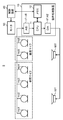
- FIG. 1 is a block diagram illustrating a schematic configuration example of a voice processing system according to the first embodiment.
- FIG. 2 is a schematic diagram showing an arrangement example of microphones and speakers provided on a seat in an aircraft.
- FIG. 3 is a block diagram illustrating a partial configuration example of the voice processing system including a functional configuration example of the CPU.
- FIG. 4A is a graph illustrating an example of a temporal change in the correlation value calculated by the correlation value calculation unit.
- FIG. 4B is a graph illustrating an example of a temporal change in the correlation value calculated by the correlation value calculation unit.
- FIG. 4C is a graph illustrating an example of temporal change of the correlation value calculated by the correlation value calculation unit.
- FIG. 4A is a graph illustrating an example of a temporal change in the correlation value calculated by the correlation value calculation unit.
- FIG. 4B is a graph illustrating an example of a temporal change in the correlation value calculated by the correlation value calculation unit.
- FIG. 4C is a
- FIG. 4D is a graph illustrating an example of a temporal change in the correlation value calculated by the correlation value calculation unit.
- FIG. 5 is a flowchart illustrating an example of an abnormality inspection operation procedure.
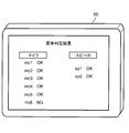
- FIG. 6 is a schematic diagram illustrating a display example of an abnormality determination result.
- FIG. 7 is a schematic diagram illustrating an example of a combination of a speaker and a plurality of microphones as a group for performing an abnormality inspection.
- FIG. 8 is a block diagram showing BPF band setting and delay time setting in Modification 1.
- FIG. 9 is a block diagram illustrating the setting of the BPF band and the delay time in the second modification.
- ANC technology can be used to reduce engine noise that can be heard on the seat side when aboard an aircraft.
- the ANC system is used on an aircraft, it is assumed that a self-diagnosis is performed and the presence or absence of an abnormality in the speaker or microphone is inspected.
- Patent Document 1 Even when there are a plurality of microphones and speakers to be inspected, it is necessary to perform an abnormality inspection one by one. Therefore, it takes a long time to complete the abnormality inspection for all the microphones and speakers. Cost. In this case, if an abnormality inspection is performed during aircraft maintenance or pre-flight preparation, the abnormality inspection takes a long time, which may be a problem. Moreover, when the sound from the speaker is not detected by the microphone, it is difficult to determine whether the microphone is abnormal or the speaker is abnormal.
- a voice processing system a voice processing apparatus, and a voice processing method that can reduce the time required for an abnormality inspection of a speaker and a microphone and determine the presence or absence of abnormality even when a plurality of microphones and speakers exist in the vehicle will be described.
- the voice processing system of this embodiment can implement ANC using a speaker and a microphone (also referred to as a microphone).
- the voice processing system inspects (abnormal inspection) whether there is an abnormality in a speaker and a microphone installed in a vehicle such as an aircraft.
- “Abnormal” here means that, for example, the speaker or microphone itself is broken, the speaker or microphone is turned off and no audio input or output is made, or a line connected to the speaker or microphone. It is conceivable that the sound signal is not transmitted and the sound signal is not transmitted, and the sound signal is not transmitted because the line connected to the speaker or the microphone is disconnected.
- This speaker and microphone are used to reduce target noise such as engine sound heard on the seat side when boarding an aircraft, for example, using ANC (Active Noise Control) technology.
- ANC Active Noise Control
- Abnormal inspections of speakers and microphones are performed during aircraft manufacturing, pre-flight preparation, maintenance, and the like.
- FIG. 1 is a block diagram illustrating a schematic configuration example of the voice processing system 5 according to the first embodiment.
- Some seats for example, first class and business class seats
- a partition 75 so as to surround, for example, a “U” shape (see FIG. 2).
- a voice processing system 5 as an ANC system that reduces noise (for example, engine sound) by ANC technology using speakers sp1 and sp2 and microphones mc1 to mc6 arranged in the partition 75 is mounted in the aircraft.
- the voice processing system 5 inspects abnormalities of the six microphones mc1 to mc6 and the two speakers sp1 and sp2.
- the sound processing system 5 has a configuration including microphones mc1 to mc6, speakers sp1 and sp2, a sound processing device 10, a control device 40, and a monitor 50.
- the number of microphones and speakers may be any number.
- the closed space surrounding the seat may be formed by the partition 75 and the wall surface, or by other methods, without being formed only by the partition 75.
- Each component of the voice processing system 5 (microphones mc1 to mc6, speakers sp1 and sp2, voice processing device 10, control device 40, and monitor 50) are all mounted on an aircraft.
- the control device 40 for example, a main system that controls the entire aircraft is assumed.
- the voice processing device 10 for example, a stationary or portable computer device that is simpler than the control device 40 and includes a processor and a memory is assumed.
- FIG. 2 is a schematic diagram showing an arrangement example of six microphones mc1 to mc6 and two speakers sp1 and sp2 provided on a seat 71 in the aircraft.
- a region Ra indicated by dots exemplifies a range where the ANC effect is expected for the passenger hm.
- the arrangement of FIG. 2 need not be changed during operation of the aircraft or during maintenance. That is, the arrangement of the microphone and the speaker may be the same when the aircraft actually flies or when an abnormality inspection is performed.
- the six microphones mc1 to mc6 are divided into four reference microphones mc1 to mc4 and two error microphones mc5 and mc6.
- the reference microphone and the error microphone are not distinguished from each other and are handled equally.
- the four reference microphones mc1 to mc4 are arranged in a row above a partition 75 standing in front of a seat (seat) 71 on which the passenger hm is seated, for example, and surrounding sounds (for example, engine sounds and other sounds) ).
- the engine sound is a sound having a band of 500 Hz to 1 kHz, for example.
- the two error microphones mc5 and mc6 are arranged side by side below the front partition 75, and collect the sound output from the speakers sp1 and sp2 and the surrounding sound together. Sound.
- the two speakers sp1, sp2 are arranged, for example, so as to face below a pair of partitions 75 provided on both sides of the seat 71.
- the two speakers sp1 and sp2 output a sound in which the surrounding sound is converted to an opposite phase in order to eliminate the surrounding sound.
- the “speech” handled by the microphone and the speaker included in the speech processing system 5 includes a wide range of speech spoken by humans, speech of animals other than humans, environmental sounds, engine sounds, mechanical sounds, and other sounds.
- the speech processing apparatus 10 includes a CPU (Central Processing Unit) 11, a memory 12, A / D converters c1 to c6, and D / A converters e1 and e2.
- CPU Central Processing Unit
- memory 12 A / D converters c1 to c6, and D / A converters e1 and e2.
- the A / D converters c1 to c6 convert the analog sound signals collected by the six microphones mc1 to mc6 into digital sound data (also simply referred to as sound data), respectively.
- the CPU 11 executes the program stored in the memory 12 to control the operation of each unit in the speech processing apparatus 10 and performs an abnormality inspection operation described later. Further, the CPU 11 inputs audio data from the A / D converters c1 to c6 and performs various processes on the audio data.
- the CPU 11 is an example of a processor, and may be configured by another processor (for example, a DSP (Digital Signal Processor)).
- the memory 12 includes a primary storage device such as a RAM (Random Access Memory) and a ROM (Read Only Memory).
- the memory 12 may include a secondary storage device such as an HDD (Hard Disk Drive) or an SSD (Solid State Drive).
- the memory 12 stores various data, programs, and setting information.
- D / A converters e1 and e2 convert the audio data output from the CPU 11 into an analog audio signal (also simply referred to as an audio signal).
- the converted audio signal is sent to the speakers sp1 and sp2.
- the control device 40 performs settings related to parameters of one or more audio processing devices 10 (for example, a pass band of a filter and a delay time of a delay device). For example, the control device 40 sets information such as passbands of BPFs (Band Pass Filters) 21 to 28 described later and delay times of the delay units 31 to 36.
- the control device 40 and the audio processing device 10 may be connected by either a wired communication line or a wireless communication line, and various settings may be made using communication. Various settings may be made without using communication.
- the monitor 50 displays various information under the control of the control device 40.
- the monitor 50 displays a later-described correlation value graph (see FIG. 4) and an abnormality inspection result (abnormality determination result) of a speaker or a microphone.
- FIG. 3 is a block diagram illustrating a configuration example of a part of the voice processing system 5 including a functional configuration example of the CPU 11.
- the CPU 11 includes six BPFs 21 to 26 for microphones, two BPFs 27 and 28 for speakers, delay units 31 to 36, adders 13 and 14, correlation value calculation units 15 and 16, abnormality determination units 17 and 18, and control. Part 20.
- FIG. 3 illustrates that the CPU 11 functionally has functions of each unit, dedicated hardware for realizing each function may be provided.
- BPFs 21 to 26 for microphones pass audio data having bands of 0 to 1 kHz, 1 to 2 kHz, 2 to 3 kHz, 3 to 4 kHz, 4 to 5 kHz, and 5 to 6 kHz, respectively.
- the speaker BPFs 27 and 28 pass audio data having bands of 0 to 3 kHz and 3 to 6 kHz, respectively. Note that each of the above pass bands of the audio data is an example, and the pass band is arbitrary.
- Delay units 31 to 33 delay the voice data extracted by the BPFs 21 to 23 by 10 msec, 20 msec, and 30 msec, respectively.
- the delay units 34 to 36 delay the voice data extracted by the BPFs 24 to 26 by 10 msec, 20 msec, and 30 msec, respectively.
- Each delay time is an example, and the length of the delay time is arbitrary.
- the adder 13 adds the audio data output from the delay units 31, 32, and 33 and outputs the result.
- the correlation value calculation unit 15 calculates a correlation value between the audio data output from the adder 13 and the audio data (white noise audio data in FIG. 3) output from the speaker BPFs 27 and 28, respectively.
- the abnormality determination unit 17 determines the speaker sp1 and the microphone mc1 based on the comparison result between the correlation value calculated by the correlation value calculation unit 15 and the threshold th1 at each timing according to the delay time of the delay units 31, 32, and 33. Determine whether there is an abnormality in mc3. For example, when the correlation value is less than the threshold th1 at a predetermined timing, the abnormality determination unit 17 determines that there is an abnormality in the microphone corresponding to the predetermined timing. On the other hand, when the correlation value is greater than or equal to the threshold th1 at a predetermined timing, the abnormality determination unit 17 determines that the microphone corresponding to the predetermined timing is normal. The determination result of the abnormality determination unit 17 is input to the control unit 20. Details of the abnormality determination will be described later.
- the adder 14 adds and outputs the audio data output from the delay units 34, 35, and 36.
- the correlation value calculation unit 16 calculates a correlation value between the audio data output from the adder 14 and the audio data (white noise in FIG. 3) output from the speaker BPFs 27 and 28, respectively.
- the abnormality determination unit 18 determines the speaker sp2 and the microphone mc4 based on the comparison result between the correlation value calculated by the correlation value calculation unit 16 and the threshold th1 at each timing according to the delay time of the delay units 34, 35, and 36. Determine whether there is an abnormality in mc6. For example, when the correlation value is less than the threshold th1 at a predetermined timing, the abnormality determination unit 18 determines that there is an abnormality in the microphone corresponding to the predetermined timing. On the other hand, when the correlation value is equal to or greater than the threshold th1 at a predetermined timing, the abnormality determination unit 18 determines that the microphone corresponding to the predetermined timing is normal. The determination result of the abnormality determination unit 18 is input to the control unit 20. Details of the abnormality determination will be described later.
- control unit 20 When the control unit 20 inputs the passband values of the BPFs 21 to 28 and the delay time values of the delay units 31 to 36 from the control device 40, the control unit 20 sets these values and stores the setting information in the memory 12. Further, the control unit 20 outputs the determination results by the abnormality determination units 17 and 18 to the control device 40.
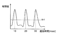
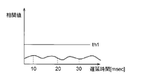
- FIGS. 4A to 4D are graphs showing examples of temporal changes in correlation values calculated by the correlation value calculation units 15 and 16.
- the vertical axis of the graph indicates the correlation value
- the horizontal axis indicates the time. Since the time at which the correlation value is calculated shifts backward as the delay time of the delay device increases, the time on the horizontal axis corresponds to the length of the delay time.
- a combination of the microphones mc1, mc2, mc3 and the speaker sp1 is set as one group for abnormality inspection.
- the combination of the microphones mc4, mc5, mc6 and the speaker sp2 is set as another group for abnormality inspection. Note that it is arbitrary which one or more microphones and which one or more speakers are combined into a group.
- the abnormality inspection may be performed simultaneously or at different timings.
- the audio processing system 5 can perform the abnormality determination of the speaker and the microphone quickly without being confused even if the abnormality inspection is performed in a plurality of groups at the same time because the frequency bands of the audio data used for the abnormality inspection are different.
- the band (for example, 0 to 3 kHz) including the pass band of the BPF (for example, BPF 21, 22, 23) connected to each microphone (for example, the microphones mc1, mc2, mc3) It is included in or coincides with a band (for example, 0 to 3 kHz) including a pass band of a BPF (for example, BPF 27) connected to the speaker (for example, the speaker sp1).
- correlation value peaks appear at delay times of 10 msec, 20 msec, and 30 msec.
- the abnormality determining unit 17 determines that the abnormality inspection target speaker sp1 and all the microphones mc1, mc2, mc3 are normal.
- the abnormality determination unit 17 determines that the speaker sp1 and the microphones mc2 and mc3 to be abnormally tested are normal and the microphone mc1 is abnormal.
- the abnormality determination unit 17 determines that the speaker sp1 and the microphone mc2 to be inspected for abnormality are normal and the two microphones mc1 and mc3 are abnormal.
- the abnormality determination unit 17 determines that all of the speaker sp1 or the three microphones mc1, mc2, mc3 are abnormal.
- the speaker sp1 When the speaker sp1 is abnormal, the speaker sp1 does not emit sound, and therefore, it is assumed that all the microphones mc1 to mc3 cannot pick up sound at all. Further, even if the speaker sp1 emits sound, if all the microphones mc1 to mc3 are abnormal, it is assumed that the microphones mc1 to mc3 cannot pick up the sound at all.
- an abnormality inspection is performed without distinguishing between the reference microphones mc1 to mc4 and the error microphones mc5 and mc6.
- the abnormality inspection is performed with the reference microphones mc1 to mc3 as the first group and the reference microphone mc4 and the error microphones mc5 and mc6 as the second group.
- the reference microphones mc1 to mc3 collect the sound emitted from the speaker sp1.
- the reference microphone mc4 and the error microphones mc5 and mc6 collect the sound emitted from the speaker sp2.
- FIG. 5 is a flowchart showing an example of an abnormality inspection operation procedure.
- the abnormality inspection operation is executed by the CPU 11.
- abnormality inspection is performed simultaneously in the first group and the second group.
- the control unit 20 in the CPU 11 sends audio data (for example, white noise audio data) stored in the memory 12 to the speakers sp1 and sp2, and outputs audio from the speakers sp1 and sp2 (S1).
- audio data for example, white noise audio data
- the sound emitted from the speaker sp1 is collected by the microphones mc1 to mc3.
- Audio signals collected by the microphones mc1 to mc3 are converted into audio data by the A / D converters c1 to c3, respectively.
- These audio data are divided into audio data of 0 to 1 kHz, audio data of 1 to 2 kHz, and audio data of 2 to 3 kHz by the BPFs 21 to 23, respectively. Therefore, the audio data that has passed through the BPFs 21 to 23 are distinguished as data corresponding to the microphones mc1 to mc3, respectively.
- the audio data of 0 to 1 kHz, the audio data of 1 to 2 kHz, and the audio data of 2 to 3 kHz are input to the adder 13 with delay times of 10 msec, 20 msec, and 30 msec by the delay units 31, 32, and 33, respectively.
- the adder 13 adds these audio data and outputs them.
- the sound emitted from the speaker sp2 is collected by the microphones mc4 to mc6.
- Audio signals collected by the microphones mc4 to mc6 are converted into audio data by the A / D converters c4 to c6, respectively.
- These audio data are divided into 3 to 4 kHz audio data, 4 to 5 kHz audio data, and 5 to 6 kHz audio data by the BPFs 24 to 26, respectively. Accordingly, the audio data that has passed through the BPFs 24 to 26 is distinguished as data corresponding to the microphones mc4 to mc6, respectively.
- the audio data of 3 to 4 kHz, the audio data of 4 to 5 kHz, and the audio data of 5 to 6 kHz are input to the adder 14 with delay times of 10 msec, 20 msec, and 30 msec by the delay units 34, 35, and 36, respectively.
- the adder 14 adds these audio data and outputs them.
- Correlation value calculation units 15 and 16 calculate correlation values according to, for example, (Equation 1) for the audio data from adders 13 and 14, respectively (S2).
- ⁇ is a shift time (delay time) obtained by temporally shifting the microphone signal (audio signal input to the microphone), and corresponds to the time axis of the correlation function.
- m ( ⁇ t) represents a microphone signal shifted by ⁇ time.
- t represents the current time in the speaker signal (audio signal output from the speaker) and the microphone signal.
- s (t) represents a speaker signal.
- C ( ⁇ ) represents a correlation function.
- the abnormality determination units 17 and 18 determine the peak of the correlation value calculated by the correlation value calculation units 15 and 16, respectively (S3).
- the correlation value peak determination for example, in the vicinity of delay times of 10 msec, 20 msec, and 30 msec, the audio signal input from the microphone corresponding to the audio signal output from the speakers sp1 and sp2 is equal to or greater than a preset threshold th1. If it is, it is determined that there is a peak. On the other hand, if the audio signal input from the microphone corresponding to the audio signals output from the speakers sp1 and sp2 is less than the threshold th1, it is determined that there is no peak. Moreover, the abnormality determination units 17 and 18 count the number of existing peaks.
- the abnormality determination units 17 and 18 determine whether or not the number of peaks is 0 as a result of the peak determination (S4). When the number of peaks is not 0, the abnormality determination units 17 and 18 determine whether or not there is a peak in the corresponding delay time (here, 10 msec, 20 msec, and 30 msec) (S5).
- the abnormality determination unit 17 determines that the speaker sp1 and the microphones mc1, mc2, mc3 are normal (S6). Similarly, the abnormality determination unit 18 determines that the speaker sp2 and the microphones mc4, mc5, and mc6 are normal (S6). Thereafter, the control unit 20 ends this operation.
- the abnormality determination unit 17 sets the speaker sp1 to be normal, and among the microphones mc1, mc2, and mc3, the microphone corresponding to the absent peak is abnormal. (S7).
- the abnormality determination unit 18 determines that the microphone corresponding to the absent peak is abnormal among the microphones mc4, mc5, and mc6 with the speaker sp2 being normal (S7). Thereafter, the control unit 20 ends this operation.
- the abnormality determination unit 17 indicates that the speaker sp1 is abnormal or all the microphones mc1, mc2, mc3 are abnormal. It is determined that it is at least one (S8). Similarly, the abnormality determination unit 18 determines that at least one of the speaker sp2 is abnormal or all the microphones mc4, mc5, mc6 are abnormal (S8). Thereafter, the control unit 20 ends this operation.
- the voice processing device 10 notifies the control device 40 of the abnormality determination result.
- the control device 40 displays the abnormality determination result on the monitor 50.
- FIG. 6 is a schematic diagram illustrating a display example of the abnormality determination result displayed on the monitor 50.
- the monitor 50 displays an abnormality determination result screen.
- this abnormality determination result screen for example, “OK” is displayed when the microphone and the speaker are normal, and “NG” is displayed when the microphone and the speaker are abnormal.
- FIG. 6 illustrates that the microphone mc6 is determined to be abnormal.
- FIG. 6 illustrates the display of the abnormality determination results for all of the speakers sp1 and sp2 and microphones mc1 to mc6 that are subject to abnormality inspection, some of them may be omitted. That is, at least one abnormality determination result of the abnormality inspection target may be displayed.
- the voice processing system 5 may perform the abnormality inspection operation in a state where the BPFs 27 and 28 are replaced.
- the passband information set in the BPF 27 and the passband information set in the BPF 28 may be exchanged and set.
- the setting of the passbands of the BPFs 27 and 28 is performed by the control device 40, for example.
- the passband setting information is held in, for example, the memory 12 of the audio processing device 10.
- the microphones mc1, mc2, and mc3 pick up a signal of 0 to 3 kHz output from the speaker sp2, and when all of the microphones mc1, mc2, and mc3 are abnormal, the peak Will not appear.
- the speaker sp1 when at least one of the microphones mc1, mc2, and mc3 is normal, at least one of the microphones mc1, mc2, and mc3 outputs 0 to 3 kHz sound output from the speaker sp2. Can be picked up, so the peak of the correlation value appears.
- the voice processing system 5 can determine whether or not the microphones mc1, mc2, mc3 are abnormal.
- the microphones mc4, mc5 and mc6 pick up the 4 to 6 kHz signal output from the speaker sp1, and all of the microphones mc4, mc5 and mc6 are abnormal. In that case, no peak will appear.
- the speaker sp2 when at least one of the microphones mc4, mc5, and mc6 is normal, at least one of the microphones mc4, mc5, and mc6 outputs 4 to 6 kHz sound output from the speaker sp1. Can be picked up, so a peak appears.
- the voice processing system 5 can determine whether or not the microphones mc4, mc5, and mc6 are abnormal.
- the control unit 20 controls the BPF 21 so that the pass bands of the BPFs 21 to 26 corresponding to all the microphones mc1 to mc6 are 0 to 1 kHz.
- the pass band of .about.26 may be set to be sequentially switched to 0 to 1 kHz.
- the passbands of the BPFs 21 to 26 corresponding to the microphones mc1 to mc6 may be switched by round robin.
- the setting of the pass band is performed by the control device 40, for example.
- control device 40 sequentially changes the passbands of the BPFs 21 to 26 corresponding to the microphones mc1 to mc6, and abnormally checks the 0 to 1 kHz band corresponding to the frequency band of the engine sound for all the microphones.
- the accuracy of suppressing engine noise which is considered to be the main noise in aircraft, can be improved.
- the voice processing system 5 abnormally inspects the BPF 21 to 26 in the 0 to 1 kHz band, which is the main band of the engine sound, so that all the microphones mc1 to mc6 include the engine sound. It is possible to determine whether or not there is no sound.
- FIG. 2 illustrates the combination of the speaker sp1 and the microphones mc1, mc2, mc3 as the first group for performing the abnormality inspection.
- the speaker sp2 and the microphones mc4, mc5, and mc6 are combined.
- the combination of the speaker and the plurality of microphones may be other combinations and can be arbitrarily changed.
- a group in which a speaker and a microphone are close to each other may be combined to form one group to be subjected to an abnormality inspection.
- the magnitude of the correlation value calculated by the correlation value calculation units 15 and 16 depends on the signal level of the audio signal input by the microphone. Since each microphone inputs sound for abnormality inspection from the speaker, it is easier to input a sound signal output from the speaker if it is located at a short distance from the speaker. Therefore, by combining speakers and microphones that are close to each other to form a group, the voice processing system 5 can easily determine the peak of the correlation value, and improve the accuracy of the abnormality inspection.
- FIG. 7 is a schematic diagram showing a case where a speaker and a plurality of microphones that are close to each other are combined as a group for performing an abnormality inspection.
- the short distance means that the speaker and microphone devices are located within a predetermined distance range from each other.
- the A groove includes a speaker sp1 and three microphones mc1, mc2, and mc5 having a short distance from the speaker sp1.
- a speaker and a microphone of group A are arranged in the first section 111.
- the B group includes a speaker sp2 and three microphones mc3, mc4, and mc6 that are short from the speaker sp2.
- a speaker and a microphone of group B are arranged in the second section 112 in the second section 112.
- the voice processing system 5 picks up the voices emitted from the speakers sp1 that are close to each other, and the microphones mc1, mc2, mc5 collect the sounds and perform an abnormality inspection. In addition, the voice processing system 5 picks up the sounds emitted from the speakers sp2 at a short distance from each other by the microphones mc3, mc4, and mc6 and performs an abnormality inspection.
- the speech processing system 5 can improve the determination accuracy of the abnormality determination obtained by comparing the correlation value with the threshold value th1.
- the voice processing system 5 can improve the accuracy of the abnormality inspection.
- the number of microphones assigned as an abnormality inspection target of the same group to one speaker is exemplified. Instead, a different number of microphones may be assigned to one speaker as an abnormality inspection target of the same group for each section that is in a short distance range from the speaker. The same applies to the case of FIG.
- the voice processing system 5 including a speaker and a plurality of microphones arranged near one seat (area) is illustrated.
- the control apparatus 40 may operate the audio processing system 5 including a speaker and a plurality of microphones arranged in the vicinity (area) of two or more seats simultaneously (at the same timing).
- the audio processing system 5 is configured to collect sound emitted from a speaker or a plurality of microphones in a plurality of areas. Anomaly inspection is performed separately for each area so as not to be audible.
- the sound processing device 10 is provided for each area. That is, the sound processing system 5 in the first and second modifications includes a plurality of sound processing devices 10 (see FIGS. 8 and 9).
- the voice processing system 5 performs an abnormality inspection by dividing a voice band used for an abnormality inspection for each adjacent area.
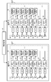
- FIG. 8 is a schematic diagram showing an example of BPF band setting and delay time setting in the first modification.
- FIG. 8 some blocks in the audio processing apparatus 10 are shown, and some symbols are omitted.
- an abnormality inspection is performed using voices with bands of 0 to 3 kHz and 3 kHz to 6 kHz as in the above embodiment.
- an abnormality inspection is performed using sounds with bands of 6 to 9 kHz and 9 to 12 kHz.
- the speaker sp11 outputs 6-9 kHz sound that has passed through the BPF 127.
- the BPFs 121 to 123 pass sounds of 6 to 7 kHz, 7 to 8 kHz, and 8 to 9 kHz collected by the microphones mc11 to mc13, respectively.
- the speaker sp12 outputs 9 to 12 kHz sound that has passed through the BPF128.
- the BPFs 124 to 126 pass the 9 to 10 kHz, 10 to 11 kHz, and 11 to 12 kHz sounds collected by the microphones mc14 to mc16, respectively.
- the control device 40 may set the BPF band in each of the sound processing devices 10 so as to handle the sound of different bands in the first area are1 and the second area are2. For example, the control device 40 sets a band of 0 to 6 kHz as the BPF band of the sound processing device 10 in the first area are1. The control device 40 sets a band of 6 to 12 kHz as the BPF band of the sound processing device 10 in the second area are2.
- the sound processing system 5 can prevent the sound related to the abnormality inspection from being confused for each area even if the abnormality inspection is performed at the same time in a plurality of seats (areas). Inspection is possible.
- the voice processing system 5 is able to reduce the influence of the abnormality inspection performed in the adjacent or adjacent area even when the abnormality inspection of the plurality of microphones and speakers used in the ANC system in the aircraft is performed simultaneously in the area unit. Can be suppressed.
- the voice processing system 5 performs an abnormality inspection by shifting the timing for each adjacent area.
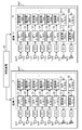
- FIG. 9 is a schematic diagram showing an example of BPF band setting and delay time setting in Modification 2. Note that, as in the first modification, in order to make the description easy to understand, in FIG. 9, some blocks in the audio processing device 10 are shown, and some symbols are omitted.
- the timings of the sounds output from the speakers sp11 and sp12 are delayed by 100 msec from the timings of the sounds output from the speakers sp1 and sp2 in the first area are1, respectively.
- delay devices 137 and 138 are provided. The delay devices 137 and 138 are included in the CPU 11 of the sound processing device 10 in the second area are2.
- the delay is 100 msec as an example, but this delay time is arbitrary, for example, 200 msec, 300 msec may be delayed.
- delay devices 37 and 38 are provided for the speakers sp1 and sp2 in the first area are1 near the first seat, but the set delay time is a value of 0, which is substantially This is the same as when no delay device is provided.
- a delay time may be arbitrarily set for the delay devices 37 and 38.
- the delay times set in the delay devices 137 and 138 on the speakers sp11 and sp12 side in the second area are2 may be set so as to be delayed according to the delay times of the delay devices 37 and 38. That is, the delay times of the delay devices 37 and 38 in the first area are different from the delay times of the delay devices 137 and 138 in the second area are2, and it is only necessary that the correlation value peaks can be distinguished and recognized.
- the audio processing device 10 in the second area are2 is provided with BPFs 127a and 128a connected to the delay units 137 and 138.
- the BPFs 127a and 128a have different passbands from the BPFs 127 and 128 included in the audio processing device 10 in the first area are1, which is different from the first modification. That is, the BPF 127a passes audio data of 0 to 3 kHz.
- the BPF 128a passes audio data of 3 to 6 kHz.
- the control device 40 may set different delay times in the respective sound processing devices 10 corresponding to the respective areas in the first area are1 and the second area are2. For example, the control device 40 sets the value 0 as the delay time for the speakers sp1 and sp2 by the sound processing device 10 that handles the signals of the speakers and microphones in the first area are1. The control device 40 sets 100 ms as a delay time for the speakers sp11 and sp12 by the sound processing device 10 in the second area are2.
- the sound processing system 5 can prevent the sound related to the abnormality inspection from being confused for each area even if the abnormality inspection is performed at the same time in a plurality of seats (areas). Inspection is possible.
- the audio processing system 5 performs the inspection in the adjacent or adjacent area even when the abnormality inspection of the plurality of microphones and speakers used in the ANC system in the aircraft is performed simultaneously on an area basis. The effects of abnormal tests can be suppressed.
- the first and second modifications for example, in the maintenance of an aircraft at an airport or preparation before a flight, it is possible to shorten the time required for an abnormal inspection of a speaker or microphone for performing ANC and efficiently perform an abnormal inspection.
- the audio processing system 5 includes a speaker and a microphone that are used in the ANC system at the same time in a plurality of areas. A microphone abnormality test can be performed. Therefore, the voice processing system 5 can shorten the time required for the abnormality inspection and improve the inspection efficiency.
- the audio processing system 5 separates the audio for each area even if the audio to be inspected for abnormality leaks into the microphone from the adjacent area. Can be recognized. Therefore, the voice processing system 5 can recognize the voice in the own area by excluding the voice in the other area. Therefore, the voice processing system 5 can suppress a decrease in accuracy of the abnormality inspection even if the abnormality inspection is performed simultaneously (at once) in a plurality of areas.
- the speaker sp1 when detecting an abnormality using sound, for example, the speaker sp1 outputs sound.
- the plurality of microphones mc1 to mc3 collect sound.
- the plurality of BPFs 21 to 23 pass the audio signals of the sounds collected by the plurality of microphones mc1 to mc3 included in the band 0 to 3 kHz of the sound output by the speaker sp1, and pass through them in arbitrary bands.
- the plurality of delay devices 31 to 33 delay the audio signals that have passed through the plurality of BPFs 21 to 23 with delay times of 10 msec, 20 msec, and 30 msec corresponding to the bands, respectively.
- the correlation value calculation unit 15 calculates a correlation value between the plurality of audio signals delayed by the plurality of delay units 31 to 33 and the audio signal of the audio output from the speaker sp1.
- the abnormality determination unit 17 determines the presence / absence of abnormality of the plurality of microphones mc1 to mc3 and the speaker sp1 based on the calculated correlation value.
- the microphones mc1 to mc3 are examples of microphones.
- BPF 21 to 23 are examples of the first filter.
- the delay devices 31 to 33 are an example of a first delay device.
- the abnormality determination unit 17 is an example of a determination unit. Each band of 0 to 1 kHz, 1 to 2 kHz, and 2 to 3 kHz is an example of the first band.
- the audio processing system 5 delays the audio signal input to the microphone for each microphone, a correlation value peak appears at a different time position for each microphone. Therefore, the time position at which the peak of the correlation value appears indicates which of the abnormality inspection target speaker or the plurality of microphones is abnormal.
- the speech processing system 5 uses the correlation value at the time corresponding to the delay time of each of the delay units 31 to 33, so that even if a part of the correlation value is not detected, the speaker or the plurality of microphones to be inspected for abnormality It is possible to determine which of these includes an abnormality.
- the voice processing system 5 can perform abnormality inspection for a plurality of microphones at the same time, improve inspection efficiency, and shorten the time required for abnormality inspection. Therefore, the voice processing system 5 can shorten the time required for aircraft maintenance and pre-flight preparation, for example.
- the voice processing system 5 since the voice processing system 5 is used for the ANC system, it can be said to be a noise cancellation system.
- the voice processing device 10 diagnoses the presence or absence of an abnormality of the microphone or the speaker included in the voice processing system 5, it can be said that the voice processing system 10 has a self-diagnosis function related to the abnormality inspection.
- the bands of the plurality of BPFs 21 to 23 may be different bands 0 to 1 kHz, 1 to 2 kHz, and 2 to 3 kHz, respectively.
- the correlation value at a time position other than the correlation peak is smaller than when there is an overlap in the bands of the plurality of BPFs 21 to 23. Therefore, the difference between the correlation value peak time position and the correlation value peak time position other than the correlation value peak becomes large. Therefore, the voice processing system 5 can improve the accuracy of determining whether there is an abnormality. Moreover, since the band of the test object corresponding to each microphone becomes narrow when the band of the sound signal of each microphone is different, the sound processing system 5 can reduce the processing load related to the abnormality determination.
- the voice processing system 5 may include a monitor 50 that displays information on the presence / absence of at least one abnormality of the plurality of microphones mc1 to mc3 and the speaker sp1 determined by the abnormality determination unit 17.
- the monitor 50 is an example of a display unit.
- the speaker sp1 may output sound of a predetermined band.
- the BPFs 21 to 23 may pass audio signals in a band included in the predetermined band.
- the voice processing system 5 can pick up a voice of an arbitrary band for each of the microphones mc1 to mc6 and determine whether or not there is an abnormality. Therefore, the voice processing system 5 can suppress noise generated by the target to be muted.
- the predetermined band may be a band including 0 to 1 kHz.
- the voice processing system 5 can pick up the sound of the band including 0 to 1 kHz which is the band of the engine sound for each of the microphones mc1 to mc6, and can determine the presence or absence of the abnormality. Accordingly, it is possible to appropriately perform an abnormality inspection of a plurality of microphones and speakers used in an ANC system such as an aircraft. Therefore, the voice processing system 5 can output the sound having the opposite phase to the engine sound of the aircraft or the like from the speaker, and can suppress the engine sound in the vicinity of the user.
- the audio processing system 5 may include a plurality of BPFs 27 and 28 that respectively pass audio signals of 0 to 3 kHz and 3 to 6 kHz (a plurality of different bands).
- the speakers sp1 and sp2 may input audio signals that have passed through the BPFs 27 and 28 and output audio based on the audio signals.
- the first group may be formed by combining the microphones mc1 to mc3 that are a part of the plurality of microphones mc1 to mc6 and the speaker sp1 that is a part of the plurality of speakers sp1 and sp2.
- the second group may be formed by combining the microphones mc4 to mc6 which are a part of the plurality of microphones mc1 to mc6 and the speaker sp2 which is a part of the plurality of speakers sp1 and sp2.
- Bands 0 to 1 kHz, 1 to 2 kHz, and 2 to 3 kHz of BPF 21 to 23 corresponding to microphones mc 1 to mc 3 belonging to the first group are included in a band 0 to 3 kHz of BPF 27 corresponding to speaker sp 1 belonging to the first group. May be.
- the bands 3 to 4 kHz, 4 to 5 kHz, and 5 to 6 kHz of the BPF 24 to 26 corresponding to the microphones mc4 to mc6 belonging to the second group are included in the band 4 to 6 kHz of the BPF 28 corresponding to the speaker sp2 belonging to the second group. May be.
- BPFs 27 and 28 are examples of the second filter.
- the speaker sp1 is an example of a first speaker.
- the speaker sp2 is an example of a second speaker.
- the sound processing system 5 divides the output band of the sound for abnormality inspection so that the microphones mc1 to mc3, mc4 to mc6, and The BPFs 21 to 23 and 24 to 26 can detect by inputting respective voices. Therefore, the voice processing system 5 can perform abnormality inspection of a plurality of speakers and a plurality of microphones at a time even when a plurality of speakers are simultaneously sounded. Therefore, the voice processing system 5 can improve the inspection efficiency of the abnormality inspection and can quickly perform the abnormality inspection.
- the voice processing system 5 may include a control device 40 that sets parameters of the voice processing device 10.
- the control device 40 The band 0 to 3 kHz of the BPF 27 corresponding to the speaker sp1 belonging to the group and the band 3 to 6 kHz of the BPF 28 corresponding to the speaker sp2 belonging to the second group may be set interchangeably.
- the audio processing system 5 has a correlation value between the plurality of audio signals collected and delayed by the plurality of microphones mc1 to mc3 and the audio signal of the audio output from the speaker sp1 at a time less than the threshold th1. If the correlation is not obtained, the band information of the BPF 27 and the band information of the BPF 28 are switched. Therefore, the sound processing system 5 receives the sound output from the speaker sp2 by the microphones mc1 to mc3, and again performs an abnormality check, so that the speaker sp1 is abnormal or all of the plurality of microphones mc1 to mc3 are abnormal. It can be determined whether there is. Therefore, when the audio processing system 5 includes a plurality of speakers, even if some of the speakers are abnormal, it can determine the abnormality.
- the first group may include a speaker sp1 and a plurality of microphones mc1, mc2, and mc5 arranged within a predetermined distance from the speaker sp1.
- the second group may include a speaker sp2 and a plurality of microphones mc3, mc4, and mc6 disposed within a predetermined distance from the speaker sp2.
- a group for abnormality inspection may be formed by a combination of these.
- the sound processing system 5 picks up the sound emitted from the speaker sp1 at a short distance, and the microphones mc1, mc2, mc5 pick up the sound and inspects it abnormally, so that it is easy to collect the sound emitted from the speaker sp1. . Therefore, the voice processing system 5 can easily determine the peak of the correlation value, and can improve the accuracy of the abnormality inspection.
- the voice processing system 5 may include a plurality of microphones, speakers, and a voice processing device 10 in a plurality of areas including the first area are1 and the second area are2. At least one group including a plurality of microphones and speakers may be formed for each area.
- the control device 40 transmits the band 0 to 6 kHz of the BPF 21 to 26 corresponding to the microphones mc1 to mc6 provided in the first area are1 and the band 0 of the BPF 27 and 28 corresponding to the speakers sp1 and sp2 provided to the first area are1.
- ⁇ 6 kHz may be set to a band included in a predetermined band (for example, 0 to 6 kHz).
- the control device 40 includes bands 6 to 12 kHz of BPF 121 to 126 corresponding to the microphones mc11 to mc16 provided in the second area are2 and bands 6 of BPF 127 and 128 corresponding to the speakers sp11 and sp12 provided in the second area are2.
- ⁇ 12 kHz may be set to a band included in another predetermined band (for example, 6 to 12 kHz) different from the predetermined band.
- the audio processing system 5 has a band divided for each area. It can recognize the sound emitted from the speaker. That is, the audio processing system 5 can make an abnormality determination by excluding an audio signal emitted from a speaker in another area from audio signals input by a microphone in the area.
- the audio processing device 10 according to the second area are2 may include delay devices 137 and 138 for delaying audio signals input to the speakers sp11 and sp12 provided in the second area are2.
- Delay devices 137 and 138 are examples of a second delay device.
- the audio processing system 5 can, for example, simultaneously perform abnormality inspections of a plurality of microphones and speakers used for ANC for each adjacent area, so that the delay time is divided for each area. Can recognize the sound emitted by the speaker. That is, the audio processing system 5 can make an abnormality determination by excluding an audio signal emitted from a speaker in another area from audio signals input by a microphone in the area.
- the audio signal output from the speakers sp1 and sp2 in the first area are1 may be delayed using a delay device or may not be delayed.
- the voice processing system 5 exemplifies that the passbands of the BPFs 21 to 26 are different from each other.
- the passbands of the BPFs 21 to 26 may be any bands included in the audio band output from the speakers sp1 and sp2.
- all the pass bands of BPF 21 to BPF 23 may be 0 to 3 kHz, which is the same as the pass band of speaker sp1.
- the passbands of BPF21 to BPF22 may be set to 0 to 2 kHz and 1 to 3 kHz, respectively, which are partially overlapped.
- the time positions at which the correlation values of the audio signals input from the microphones mc1 to mc3 appear by the delay units 31 to 33 are different. It can be used to determine abnormality.
- the audio processing system 5 delays the audio signals input to the microphones mc1 to mc3 for each band, so that correlation value peaks appear at different time positions for each band. Further, when the audio signals delayed by the delay units 31 to 33 are added, the level of the added audio signal becomes relatively small at a time position other than the peak of the correlation value (see FIG. 4A). . Therefore, the difference between the correlation values at the time position of the correlation value peak (for example, 10 ms, 20 ms, and 30 ms) and the time position other than the correlation value peak (for example, the time position other than 10 ms, 20 ms, and 30 ms) becomes large.
- the voice processing system 5 can improve the accuracy of determining whether there is an abnormality. Moreover, since the band of the inspection target corresponding to each microphone is narrowed by making the band of the sound signal of each microphone different, the sound processing system 5 can reduce the processing load related to the abnormality determination.
- an example of performing abnormality inspection of six microphones (four reference microphones and two error microphones) and two speakers used in the voice processing system 5 serving as an ANC system is illustrated.
- the number of microphones and speakers is not limited to this and may be arbitrarily combined.
- the voice processing system 5 forms a group with a combination of one speaker and three microphones and performs an abnormality inspection.
- the voice processing system 5 may perform an abnormality inspection on all (six) microphones with one speaker. Further, three or more groups for abnormality inspection may be formed.
- the microphone and speaker of the voice processing system 5 are exemplified as being mounted on an aircraft, but may be mounted on a vehicle other than an aircraft (for example, a car, a ship, a rocket).
- the microphone of the audio processing system 5 is exemplified as including the reference microphone and the error microphone, but either one may be omitted.
- the reference microphone can be omitted.
- audio data other than the white noise may be input.
- audio data having a predetermined band may be input to the BPFs 27 and 28 instead of audio data whose band is not determined such as white noise.
- the audio data having the predetermined band may be wider than a band (for example, 0 to 6 kHz) in which an abnormality inspection of the microphone and the speaker is performed.
- one area is exemplified as being near one seat, but one area may include two or more seats.
- the voice processing system 5 may output a voice signal from the speaker while avoiding the engine sound band (for example, 500 Hz to 1 kHz). This is because the engine sound is always present during the flight. Thereby, the processing load of the voice processing apparatus 10 related to the abnormality inspection is reduced.
- the engine sound band for example, 500 Hz to 1 kHz
- the processor may be physically configured in any manner. Further, if a programmable processor is used, the processing contents can be changed by changing the program, so that the degree of freedom in designing the processor can be increased.
- the processor may be composed of one semiconductor chip or physically composed of a plurality of semiconductor chips. When configured by a plurality of semiconductor chips, each control of the first embodiment may be realized by separate semiconductor chips. In this case, it can be considered that a plurality of semiconductor chips constitute one processor.
- the processor may be configured by a member (capacitor or the like) having a function different from that of the semiconductor chip. Further, one semiconductor chip may be configured so as to realize the functions of the processor and other functions.
- the present disclosure relates to a voice processing system, a voice processing device, a voice processing method, and the like that can reduce the time required for an abnormality inspection of a speaker and a microphone and determine the presence or absence of abnormality even when a plurality of microphones and speakers are present in a vehicle. Useful.
- Voice processing system 10 Voice processing device 11 CPU 12 Memory 13, 14 Adder 15, 16 Correlation value calculation unit 17, 18 Abnormality determination unit 20 Control unit 21-28, 121-128, 127a, 128a BPF 31 to 36, 137, 138 Delay device 40 Control device 50 Monitor 71 Seat 75 Partition 111 First section 112 Second section are1 First area are2 Second area c1 to c6 A / D converter e1, e2 D / A Converter hm Passenger mc1 to mc6, mc11 to mc16 Microphone Ra region sp1, sp2, sp11, sp12 Speaker
Abstract
An audio processing system equipped with a speaker, multiple microphones, and an audio processing device. The audio processing device is equipped with: multiple filters that allow audio signals of sound picked up by the multiple microphones to pass in respective given first bands included in the audio band that is output from the speaker; multiple delay devices that delay, with respective delay times corresponding to the first bands, the audio signals that have passed through the multiple filters; a correlation value calculation unit that calculates a correlation value for the audio signal of the sound output from the speaker and the multiple audio signals that have been delayed respectively by the multiple delay devices; and a determination unit that, on the basis of the correlation value, determines whether there is an abnormality in the multiple microphones and the speaker.
Description
本開示は、音声処理システム、音声処理装置及び音声処理方法に関する。
The present disclosure relates to a voice processing system, a voice processing device, and a voice processing method.
騒音を逆位相の音で消音するANC(Active Noise Control)技術が知られている(非特許文献1参照)。ANCの制御手法はいくつか知られているが、例えばフィードフォワード方式では、参照マイクと誤差マイクと二次音源スピーカとを用いて、ANC制御する。
An ANC (Active Noise Control) technology that silences noise with a sound of opposite phase is known (see Non-Patent Document 1). Several ANC control methods are known. For example, in the feedforward method, ANC control is performed using a reference microphone, an error microphone, and a secondary sound source speaker.
参照マイクは、参照信号(例えば騒音源となる音声)を検出する。誤差マイクは、騒音の低減効果を観測するためのマイクである。二次音源スピーカは、騒音を打ち消すための疑似騒音を出力する。参照マイクで検出された信号は、騒音制御フィルタにより加工され、二次音源スピーカから出力される疑似騒音となる。騒音と疑似騒音とが相互に打消し合うことで、誤差マイクで検出される誤差信号が最小となるように、騒音制御フィルタの係数が調整される。
The reference microphone detects a reference signal (for example, a voice as a noise source). The error microphone is a microphone for observing the noise reduction effect. The secondary sound source speaker outputs pseudo noise for canceling the noise. The signal detected by the reference microphone is processed by a noise control filter and becomes pseudo noise output from the secondary sound source speaker. The noise control filter coefficient is adjusted so that the error signal detected by the error microphone is minimized by canceling out the noise and the pseudo noise.
ANCを用いて十分に騒音を低減させるためには、マイク(参照マイクや誤差マイク)とスピーカ(二次音源スピーカ)が正常に動作していることが前提である。マイクやスピーカの異常を検知する技術として、特許文献1に記載の断線検知回路が知られている。この断線検知回路は、1つのスピーカから出力された音を1つのマイクで拾い、スピーカ信号とマイク信号とを比較することで、スピーカとマイクの断線を検知する。
In order to sufficiently reduce noise using the ANC, it is assumed that the microphone (reference microphone or error microphone) and the speaker (secondary sound source speaker) are operating normally. As a technique for detecting an abnormality of a microphone or a speaker, a disconnection detection circuit described in Patent Document 1 is known. This disconnection detection circuit detects the disconnection between the speaker and the microphone by picking up the sound output from one speaker with one microphone and comparing the speaker signal and the microphone signal.
しかしながら、乗物においてマイク及びスピーカが複数存在する場合には、マイクやスピーカの異常検査を短時間で行うことが困難である。
However, when there are a plurality of microphones and speakers in the vehicle, it is difficult to perform an abnormality inspection of the microphones and speakers in a short time.
本開示は、乗物内に複数のマイク及びスピーカが存在する場合でも、スピーカやマイクの異常検査に要する時間を短縮して異常の有無を判定することを目的とする。
This disclosure is intended to determine the presence or absence of an abnormality by reducing the time required for an abnormality inspection of a speaker or a microphone even when a plurality of microphones and speakers are present in a vehicle.
本開示の音声処理システムは、音声を出力するスピーカと、音声を収音する複数のマイクロホンと、マイクロホンで収音された音声に基づいて、複数のマイクロホン及びスピーカの異常の有無を判定する音声処理装置と、を備える。音声処理装置は、複数のマイクロホンで収音された音声の音声信号を、スピーカにより出力された音声の帯域に含まれ、それぞれ任意の第1の帯域で通過させる複数の第1のフィルタと、複数の第1のフィルタを通過した音声信号を、それぞれ第1の帯域に対応する遅延時間で遅延させる複数の第1の遅延器と、複数の第1の遅延器でそれぞれ遅延した複数の音声信号と、スピーカから出力される音声の音声信号と、の相関値を算出する相関値算出部と、相関値に基づき、複数のマイクロホン及びスピーカの異常の有無を判定する判定部と、を備える。
An audio processing system according to the present disclosure includes a speaker that outputs sound, a plurality of microphones that collect sound, and sound processing that determines whether or not there is an abnormality in the plurality of microphones and the speaker based on sound collected by the microphone. An apparatus. The sound processing device includes a plurality of first filters that allow sound signals collected by a plurality of microphones to be included in a sound band output by a speaker and pass through each arbitrary first band; A plurality of first delay units that delay the audio signals that have passed through the first filter by delay times corresponding to the first bands, and a plurality of audio signals that are respectively delayed by the plurality of first delay units; A correlation value calculation unit that calculates a correlation value between the audio signal output from the speaker and a determination unit that determines presence / absence of abnormality of the plurality of microphones and the speaker based on the correlation value.
本開示の音声処理装置は、音声を出力するスピーカと、音声を収音する複数のマイクロホンと、の異常の有無を判定する。音声処理装置は、複数のマイクロホンで収音された音声の音声信号を、スピーカにより出力された音声の帯域に含まれ、それぞれ任意の第1の帯域で通過させる複数のフィルタと、複数のフィルタを通過した音声信号を、それぞれ第1の帯域に対応する遅延時間で遅延させる複数の遅延器と、複数の遅延器でそれぞれ遅延した複数の音声信号と、スピーカから出力される音声の音声信号と、の相関値を算出する相関値算出部と、相関値に基づき、複数のマイクロホン及びスピーカの異常の有無を判定する判定部と、を備える。
The audio processing device according to the present disclosure determines whether there is an abnormality between a speaker that outputs sound and a plurality of microphones that collect sound. The sound processing apparatus includes a plurality of filters that include a sound signal of sound collected by a plurality of microphones, included in a sound band output by a speaker, and each of which passes in an arbitrary first band, and a plurality of filters. A plurality of delay devices for delaying the passed audio signals by delay times corresponding to the first bands, a plurality of audio signals respectively delayed by the plurality of delay devices, and an audio signal for audio output from a speaker; A correlation value calculation unit that calculates a correlation value of the first microphone and a determination unit that determines presence / absence of abnormality of the plurality of microphones and speakers based on the correlation value.
本開示の音声処理方法は、音声を出力するスピーカと、音声を収音する複数のマイクロホンと、の異常の有無を判定する音声処理方法であって、複数のマイクロホンで収音された音声の音声信号を、スピーカにより出力された音声の帯域に含まれ、それぞれ任意の第1の帯域で通過させ、それぞれ任意の第1の帯域で通過させた音声信号を、それぞれ第1の帯域に対応する遅延時間で遅延させ、それぞれ遅延させた複数の音声信号と、スピーカから出力される音声の音声信号と、の相関値を算出し、相関値に基づき、複数のマイクロホン及びスピーカの異常の有無を判定する。
The sound processing method of the present disclosure is a sound processing method for determining whether there is an abnormality between a speaker that outputs sound and a plurality of microphones that collect sound, and the sound of sound collected by the plurality of microphones The signal is included in the band of the sound output by the speaker, passes through the arbitrary first band, and the audio signal that passes through the arbitrary first band respectively corresponds to the delay corresponding to the first band. A correlation value between a plurality of audio signals delayed by time and an audio signal output from a speaker is calculated, and the presence / absence of abnormality of a plurality of microphones and speakers is determined based on the correlation value. .
本開示によれば、乗物内に複数のマイク及びスピーカが存在する場合でも、スピーカやマイクの異常検査に要する時間を短縮して異常の有無を判定できる。
According to the present disclosure, even when there are a plurality of microphones and speakers in the vehicle, it is possible to determine the presence or absence of an abnormality by shortening the time required for an abnormality inspection of the speaker or microphone.
以下、適宜図面を参照しながら、実施形態を詳細に説明する。但し、必要以上に詳細な説明は省略する場合がある。例えば、既によく知られた事項の詳細説明や実質的に同一の構成に対する重複説明を省略する場合がある。これは、以下の説明が不必要に冗長になることを避け、当業者の理解を容易にするためである。尚、添付図面及び以下の説明は、当業者が本開示を十分に理解するために提供されるものであり、これらにより特許請求の範囲に記載の主題を限定することは意図されていない。
Hereinafter, embodiments will be described in detail with reference to the drawings as appropriate. However, more detailed description than necessary may be omitted. For example, detailed descriptions of already well-known matters and repeated descriptions for substantially the same configuration may be omitted. This is to avoid the following description from becoming unnecessarily redundant and to facilitate understanding by those skilled in the art. The accompanying drawings and the following description are provided to enable those skilled in the art to fully understand the present disclosure, and are not intended to limit the claimed subject matter.
(本開示の一形態を得るに至った経緯)
ANC技術は、航空機に搭乗している時に座席側で聞こえるエンジンの騒音を軽減するために用いることが考えられる。ANCシステムを航空機で用いる場合、自己診断を行い、スピーカやマイクの異常の有無を検査することが想定される。 (Background to obtaining one form of the present disclosure)
ANC technology can be used to reduce engine noise that can be heard on the seat side when aboard an aircraft. When the ANC system is used on an aircraft, it is assumed that a self-diagnosis is performed and the presence or absence of an abnormality in the speaker or microphone is inspected.
特許文献1の技術では、検査対象のマイクやスピーカが複数ある場合でも、1つずつ異常検査を行う必要があるため、全てのマイクやスピーカに対して異常検査が完了するまでに、長時間を要する。この場合、航空機のメンテナンスやフライト前準備の際に異常検査を行うと、異常検査に長時間を要するため、支障がある可能性がある。また、スピーカからの音声がマイクにより検出されなかった場合、マイクの異常かスピーカの異常かを切り分けることが困難である。
In the technique of Patent Document 1, even when there are a plurality of microphones and speakers to be inspected, it is necessary to perform an abnormality inspection one by one. Therefore, it takes a long time to complete the abnormality inspection for all the microphones and speakers. Cost. In this case, if an abnormality inspection is performed during aircraft maintenance or pre-flight preparation, the abnormality inspection takes a long time, which may be a problem. Moreover, when the sound from the speaker is not detected by the microphone, it is difficult to determine whether the microphone is abnormal or the speaker is abnormal.
以下、乗物内に複数のマイクやスピーカが存在する場合でも、スピーカやマイクの異常検査に要する時間を短縮して異常の有無を判定できる音声処理システム、音声処理装置及び音声処理方法について説明する。
Hereinafter, a voice processing system, a voice processing apparatus, and a voice processing method that can reduce the time required for an abnormality inspection of a speaker and a microphone and determine the presence or absence of abnormality even when a plurality of microphones and speakers exist in the vehicle will be described.
(第1の実施形態)
本実施形態の音声処理システムは、スピーカとマイクロホン(マイクともいう)を用いて、ANCを実施可能である。また、音声処理システムは、航空機等の乗物に設置されるスピーカとマイクの異常の有無を検査(異常検査)する。 (First embodiment)
The voice processing system of this embodiment can implement ANC using a speaker and a microphone (also referred to as a microphone). In addition, the voice processing system inspects (abnormal inspection) whether there is an abnormality in a speaker and a microphone installed in a vehicle such as an aircraft.
ここでの「異常」とは、例えば、スピーカやマイクそのものが故障していること、スピーカやマイクの電源がオフになっており音声入力や音声出力がされないこと、スピーカやマイクに接続される線が抜けており音声信号が伝達されないこと、スピーカやマイクに接続される線が断線しており音声信号が伝達されないこと、が考えられる。
“Abnormal” here means that, for example, the speaker or microphone itself is broken, the speaker or microphone is turned off and no audio input or output is made, or a line connected to the speaker or microphone. It is conceivable that the sound signal is not transmitted and the sound signal is not transmitted, and the sound signal is not transmitted because the line connected to the speaker or the microphone is disconnected.
このスピーカやマイクは、ANC(Active Noise Control)技術を用いて、例えば、航空機に搭乗している時に座席側で聞こえるエンジン音等のターゲットの騒音の軽減に使用される。スピーカやマイクの異常検査は、航空機の製造時、フライト前準備、メンテナンス時、等に行われる。
This speaker and microphone are used to reduce target noise such as engine sound heard on the seat side when boarding an aircraft, for example, using ANC (Active Noise Control) technology. Abnormal inspections of speakers and microphones are performed during aircraft manufacturing, pre-flight preparation, maintenance, and the like.
[構成等]
図1は、第1の実施形態における音声処理システム5の概略構成例を示すブロック図である。航空機等の一部の座席(例えばファーストクラスやビジネスクラスの座席)は、衝立(パーティション)75によって、例えば「コ」の字形に囲むように仕切られる(図2参照)。また、衝立75に配置されたスピーカsp1,sp2及びマイクmc1~mc6を用いて、ANC技術により騒音(例えばエンジン音)を低減するANCシステムとしての音声処理システム5が機内に搭載される。 [Configuration]
FIG. 1 is a block diagram illustrating a schematic configuration example of thevoice processing system 5 according to the first embodiment. Some seats (for example, first class and business class seats) of an aircraft or the like are partitioned by a partition 75 so as to surround, for example, a “U” shape (see FIG. 2). A voice processing system 5 as an ANC system that reduces noise (for example, engine sound) by ANC technology using speakers sp1 and sp2 and microphones mc1 to mc6 arranged in the partition 75 is mounted in the aircraft.
図1は、第1の実施形態における音声処理システム5の概略構成例を示すブロック図である。航空機等の一部の座席(例えばファーストクラスやビジネスクラスの座席)は、衝立(パーティション)75によって、例えば「コ」の字形に囲むように仕切られる(図2参照)。また、衝立75に配置されたスピーカsp1,sp2及びマイクmc1~mc6を用いて、ANC技術により騒音(例えばエンジン音)を低減するANCシステムとしての音声処理システム5が機内に搭載される。 [Configuration]
FIG. 1 is a block diagram illustrating a schematic configuration example of the
図1では、音声処理システム5は、6つのマイクmc1~mc6及び2つのスピーカsp1,sp2の異常を検査する。音声処理システム5は、マイクmc1~mc6と、スピーカsp1,sp2と、音声処理装置10と、制御装置40と、モニタ50と、を含む構成を有する。尚、マイク及びスピーカの数は、任意の数でよい。また、座席を囲む閉空間は、衝立75だけで形成されることなく、衝立75と壁面によって、又はその他の方法によって、形成されてもよい。
In FIG. 1, the voice processing system 5 inspects abnormalities of the six microphones mc1 to mc6 and the two speakers sp1 and sp2. The sound processing system 5 has a configuration including microphones mc1 to mc6, speakers sp1 and sp2, a sound processing device 10, a control device 40, and a monitor 50. The number of microphones and speakers may be any number. Further, the closed space surrounding the seat may be formed by the partition 75 and the wall surface, or by other methods, without being formed only by the partition 75.
音声処理システム5の各構成部(マイクmc1~mc6、スピーカsp1,sp2、音声処理装置10、制御装置40、モニタ50)は、いずれも航空機に搭載される。制御装置40としては、例えば、航空機内の全体を制御するメインシステムが想定される。音声処理装置10としては、例えば、制御装置40よりも簡易的であり、プロセッサやメモリを備える据え置き型又は携帯型のコンピュータ装置が想定される。
Each component of the voice processing system 5 (microphones mc1 to mc6, speakers sp1 and sp2, voice processing device 10, control device 40, and monitor 50) are all mounted on an aircraft. As the control device 40, for example, a main system that controls the entire aircraft is assumed. As the voice processing device 10, for example, a stationary or portable computer device that is simpler than the control device 40 and includes a processor and a memory is assumed.
図2は、航空機内の座席71に設けられた6個のマイクmc1~mc6と2個のスピーカsp1,sp2の配置例を示す模式図である。図中、ドットで示される領域Raは、搭乗者hmにとって、ANC効果が期待される範囲を例示している。図2の配置は、航空機の運用時でもメンテナンス時でも変更されなくてよい。つまり、航空機が実際にフライトする際でも、異常検査を行う際でも、マイク及びスピーカの配置は同様でよい。
FIG. 2 is a schematic diagram showing an arrangement example of six microphones mc1 to mc6 and two speakers sp1 and sp2 provided on a seat 71 in the aircraft. In the drawing, a region Ra indicated by dots exemplifies a range where the ANC effect is expected for the passenger hm. The arrangement of FIG. 2 need not be changed during operation of the aircraft or during maintenance. That is, the arrangement of the microphone and the speaker may be the same when the aircraft actually flies or when an abnormality inspection is performed.
ANCでは、6個のマイクmc1~mc6は、4個の参照マイクmc1~mc4と、2個の誤差マイクmc5,mc6と、に分けられる。但し、異常検査では、参照マイクと誤差マイクとは区別されることなく、同等に取り扱われる。
In ANC, the six microphones mc1 to mc6 are divided into four reference microphones mc1 to mc4 and two error microphones mc5 and mc6. However, in the abnormal inspection, the reference microphone and the error microphone are not distinguished from each other and are handled equally.
4個の参照マイクmc1~mc4は、例えば、搭乗者hmが着座する座席(シート)71の正面に立設した衝立75の上方に一列に配置され、周囲の音声(例えばエンジン音、その他の音)を収音する。エンジン音は、例えば、500Hz~1kHzの帯域を有する音である。
The four reference microphones mc1 to mc4 are arranged in a row above a partition 75 standing in front of a seat (seat) 71 on which the passenger hm is seated, for example, and surrounding sounds (for example, engine sounds and other sounds) ). The engine sound is a sound having a band of 500 Hz to 1 kHz, for example.
2個の誤差マイクmc5,mc6は、例えば、正面の衝立75の下方に並んで配置され、スピーカsp1,sp2から騒音を消去するために出力される音声と、周囲の音声と、を併せて収音する。
For example, the two error microphones mc5 and mc6 are arranged side by side below the front partition 75, and collect the sound output from the speakers sp1 and sp2 and the surrounding sound together. Sound.
2個のスピーカsp1,sp2は、例えば、座席71の両側に設けられた、一対の衝立75の下方に対向するように配置される。2個のスピーカsp1,sp2は、周囲の音声を消すために周囲の音声が逆位相に変換された音声を出力する。
The two speakers sp1, sp2 are arranged, for example, so as to face below a pair of partitions 75 provided on both sides of the seat 71. The two speakers sp1 and sp2 output a sound in which the surrounding sound is converted to an opposite phase in order to eliminate the surrounding sound.
尚、音声処理システム5に含まれるマイクやスピーカが扱う「音声」は、人が話す音声、人以外の動物の音声、環境音、エンジン音、機械音、その他の音を広く含む。
The “speech” handled by the microphone and the speaker included in the speech processing system 5 includes a wide range of speech spoken by humans, speech of animals other than humans, environmental sounds, engine sounds, mechanical sounds, and other sounds.
音声処理装置10は、CPU(Central Processing Unit)11、メモリ12、A/D変換器c1~c6、及びD/A変換器e1,e2を有する。
The speech processing apparatus 10 includes a CPU (Central Processing Unit) 11, a memory 12, A / D converters c1 to c6, and D / A converters e1 and e2.
A/D変換器c1~c6は、それぞれ6個のマイクmc1~mc6で収音されたアナログ音声信号をデジタル音声データ(単に音声データともいう)に変換する。
The A / D converters c1 to c6 convert the analog sound signals collected by the six microphones mc1 to mc6 into digital sound data (also simply referred to as sound data), respectively.
CPU11は、メモリ12に記憶されたプログラムを実行することで、音声処理装置10内の各部の動作を制御し、後述する異常検査動作を行う。また、CPU11は、A/D変換器c1~c6から音声データを入力し、音声データに対して各種処理する。CPU11は、プロセッサの一例であり、他のプロセッサ(例えばDSP(Digital Signal Processor))で構成されてもよい。
The CPU 11 executes the program stored in the memory 12 to control the operation of each unit in the speech processing apparatus 10 and performs an abnormality inspection operation described later. Further, the CPU 11 inputs audio data from the A / D converters c1 to c6 and performs various processes on the audio data. The CPU 11 is an example of a processor, and may be configured by another processor (for example, a DSP (Digital Signal Processor)).
メモリ12は、RAM(Random Access Memory)やROM(Read Only Memory)などの一次記憶装置を含む。メモリ12は、HDD(Hard Disk Drive)やSSD(Solid State Drive)などの二次記憶装置を含んでもよい。メモリ12は、各種データ、プログラム、設定情報を記憶する。
The memory 12 includes a primary storage device such as a RAM (Random Access Memory) and a ROM (Read Only Memory). The memory 12 may include a secondary storage device such as an HDD (Hard Disk Drive) or an SSD (Solid State Drive). The memory 12 stores various data, programs, and setting information.
D/A変換器e1,e2は、CPU11から出力された音声データを、アナログ音声信号(単に音声信号ともいう)に変換する。変換された音声信号は、スピーカsp1,sp2に送られる。
D / A converters e1 and e2 convert the audio data output from the CPU 11 into an analog audio signal (also simply referred to as an audio signal). The converted audio signal is sent to the speakers sp1 and sp2.
制御装置40は、1つ以上の音声処理装置10のパラメータ(例えばフィルタの通過帯域、遅延器の遅延時間)に係る設定を行う。例えば、制御装置40は、後述するBPF(Band Pass Filter)21~28の通過帯域や遅延器31~36の遅延時間等の情報を設定する。制御装置40と音声処理装置10とは、有線通信回線又は無線通信回線のいずれにより接続されてもよく、通信を用いて各種設定がされてもよい。また、通信を用いずに各種設定がされてもよい。
The control device 40 performs settings related to parameters of one or more audio processing devices 10 (for example, a pass band of a filter and a delay time of a delay device). For example, the control device 40 sets information such as passbands of BPFs (Band Pass Filters) 21 to 28 described later and delay times of the delay units 31 to 36. The control device 40 and the audio processing device 10 may be connected by either a wired communication line or a wireless communication line, and various settings may be made using communication. Various settings may be made without using communication.
モニタ50は、制御装置40の制御により、各種情報を表示する。例えば、モニタ50は、後述する相関値のグラフ(図4参照)、スピーカやマイクの異常検査結果(異常判定結果)を表示する。
The monitor 50 displays various information under the control of the control device 40. For example, the monitor 50 displays a later-described correlation value graph (see FIG. 4) and an abnormality inspection result (abnormality determination result) of a speaker or a microphone.
図3は、CPU11の機能的構成例を含む音声処理システム5の一部の構成例を示すブロック図である。CPU11は、マイク用の6つのBPF21~26、スピーカ用の2つのBPF27,28、遅延器31~36、加算器13,14、相関値算出部15,16、異常判定部17,18、及び制御部20を有する。尚、図3では、CPU11が機能的に各部の機能を有することを例示するが、各機能を実現するための専用のハードウェアを備えてもよい。
FIG. 3 is a block diagram illustrating a configuration example of a part of the voice processing system 5 including a functional configuration example of the CPU 11. The CPU 11 includes six BPFs 21 to 26 for microphones, two BPFs 27 and 28 for speakers, delay units 31 to 36, adders 13 and 14, correlation value calculation units 15 and 16, abnormality determination units 17 and 18, and control. Part 20. In addition, although FIG. 3 illustrates that the CPU 11 functionally has functions of each unit, dedicated hardware for realizing each function may be provided.
マイク用のBPF21~26は、それぞれ0~1kHz,1~2kHz,2~3kHz,3~4kHz,4~5kHz,5~6kHzの帯域を有する音声データを通過させる。スピーカ用のBPF27,28は、それぞれ0~3kHz、3~6kHzの帯域を有する音声データを通過させる。尚、音声データの上記の各通過帯域は一例であり、通過帯域は任意である。
BPFs 21 to 26 for microphones pass audio data having bands of 0 to 1 kHz, 1 to 2 kHz, 2 to 3 kHz, 3 to 4 kHz, 4 to 5 kHz, and 5 to 6 kHz, respectively. The speaker BPFs 27 and 28 pass audio data having bands of 0 to 3 kHz and 3 to 6 kHz, respectively. Note that each of the above pass bands of the audio data is an example, and the pass band is arbitrary.
遅延器31~33は、それぞれ、BPF21~23で抽出された音声データを、10msec,20msec,30msec遅延させる。また、遅延器34~36は、それぞれ、BPF24~26で抽出された音声データを、10msec,20msec,30msec遅延させる。尚、上記の各遅延時間は一例であり、遅延時間の長さは任意である。
Delay units 31 to 33 delay the voice data extracted by the BPFs 21 to 23 by 10 msec, 20 msec, and 30 msec, respectively. The delay units 34 to 36 delay the voice data extracted by the BPFs 24 to 26 by 10 msec, 20 msec, and 30 msec, respectively. Each delay time is an example, and the length of the delay time is arbitrary.
加算器13は、遅延器31,32,33から出力される音声データを加算して出力する。相関値算出部15は、加算器13から出力された音声データと、スピーカ用のBPF27,28からそれぞれ出力される音声データ(図3ではホワイトノイズの音声データ)と、の相関値を算出する。
The adder 13 adds the audio data output from the delay units 31, 32, and 33 and outputs the result. The correlation value calculation unit 15 calculates a correlation value between the audio data output from the adder 13 and the audio data (white noise audio data in FIG. 3) output from the speaker BPFs 27 and 28, respectively.
異常判定部17は、遅延器31,32,33の遅延時間に応じた各タイミングにおいて、相関値算出部15で算出された相関値と閾値th1との比較結果に基づいて、スピーカsp1及びマイクmc1~mc3の異常の有無を判定する。例えば、異常判定部17は、所定のタイミングにおいて相関値が閾値th1未満である場合、この所定のタイミングに対応するマイクに異常があると判定する。一方、異常判定部17は、所定のタイミングにおいて相関値が閾値th1以上である場合、この所定のタイミングに対応するマイクが正常であると判定する。異常判定部17の判定結果は、制御部20に入力される。尚、異常判定の詳細について後述する。
The abnormality determination unit 17 determines the speaker sp1 and the microphone mc1 based on the comparison result between the correlation value calculated by the correlation value calculation unit 15 and the threshold th1 at each timing according to the delay time of the delay units 31, 32, and 33. Determine whether there is an abnormality in mc3. For example, when the correlation value is less than the threshold th1 at a predetermined timing, the abnormality determination unit 17 determines that there is an abnormality in the microphone corresponding to the predetermined timing. On the other hand, when the correlation value is greater than or equal to the threshold th1 at a predetermined timing, the abnormality determination unit 17 determines that the microphone corresponding to the predetermined timing is normal. The determination result of the abnormality determination unit 17 is input to the control unit 20. Details of the abnormality determination will be described later.
同様に、加算器14は、遅延器34,35,36から出力される音声データを加算して出力する。相関値算出部16は、加算器14から出力された音声データと、スピーカ用のBPF27,28からそれぞれ出力される音声データ(図3ではホワイトノイズ)と、の相関値を算出する。
Similarly, the adder 14 adds and outputs the audio data output from the delay units 34, 35, and 36. The correlation value calculation unit 16 calculates a correlation value between the audio data output from the adder 14 and the audio data (white noise in FIG. 3) output from the speaker BPFs 27 and 28, respectively.
異常判定部18は、遅延器34,35,36の遅延時間に応じた各タイミングにおいて、相関値算出部16で算出された相関値と閾値th1との比較結果に基づいて、スピーカsp2及びマイクmc4~mc6の異常の有無を判定する。例えば、異常判定部18は、所定のタイミングにおいて相関値が閾値th1未満である場合、この所定のタイミングに対応するマイクに異常があると判定する。一方、異常判定部18は、所定のタイミングにおいて相関値が閾値th1以上である場合、この所定のタイミングに対応するマイクが正常であると判定する。異常判定部18の判定結果は、制御部20に入力される。尚、異常判定の詳細について後述する。
The abnormality determination unit 18 determines the speaker sp2 and the microphone mc4 based on the comparison result between the correlation value calculated by the correlation value calculation unit 16 and the threshold th1 at each timing according to the delay time of the delay units 34, 35, and 36. Determine whether there is an abnormality in mc6. For example, when the correlation value is less than the threshold th1 at a predetermined timing, the abnormality determination unit 18 determines that there is an abnormality in the microphone corresponding to the predetermined timing. On the other hand, when the correlation value is equal to or greater than the threshold th1 at a predetermined timing, the abnormality determination unit 18 determines that the microphone corresponding to the predetermined timing is normal. The determination result of the abnormality determination unit 18 is input to the control unit 20. Details of the abnormality determination will be described later.
制御部20は、BPF21~28の通過帯域や遅延器31~36の遅延時間の値を制御装置40から入力すると、これらの値を設定し、設定情報をメモリ12に保持させる。また、制御部20は、異常判定部17,18による判定結果を制御装置40に出力する。
When the control unit 20 inputs the passband values of the BPFs 21 to 28 and the delay time values of the delay units 31 to 36 from the control device 40, the control unit 20 sets these values and stores the setting information in the memory 12. Further, the control unit 20 outputs the determination results by the abnormality determination units 17 and 18 to the control device 40.
図4A~図4Dは、相関値算出部15,16で算出される相関値の時間変化例を示すグラフである。グラフの縦軸は相関値を示し、横軸は時刻を示す。相関値が算出される時刻は遅延器の遅延時間が大きい程、後ろにずれるので、横軸の時刻は、遅延時間の長さに相当する。
FIGS. 4A to 4D are graphs showing examples of temporal changes in correlation values calculated by the correlation value calculation units 15 and 16. The vertical axis of the graph indicates the correlation value, and the horizontal axis indicates the time. Since the time at which the correlation value is calculated shifts backward as the delay time of the delay device increases, the time on the horizontal axis corresponds to the length of the delay time.
ここでは、マイクmc1,mc2,mc3とスピーカsp1との組み合わせを、異常検査対象の1つのグループとする。また、尚、マイクmc4,mc5,mc6とスピーカsp2との組み合わせを、異常検査対象の他の1つのグループとする。尚、どの1つ以上のマイクとどの1つ以上のスピーカとを組み合わせてグループとするかは、任意である。
Here, a combination of the microphones mc1, mc2, mc3 and the speaker sp1 is set as one group for abnormality inspection. In addition, the combination of the microphones mc4, mc5, mc6 and the speaker sp2 is set as another group for abnormality inspection. Note that it is arbitrary which one or more microphones and which one or more speakers are combined into a group.
これらのグループでは、異常検査が同時に実施されてもよいし、異なるタイミングで行われてもよい。音声処理システム5は、同時に複数のグループで異常検査が行われても、異常検査に用いられる音声データの周波数帯域がそれぞれ異なるので、スピーカ及びマイクの異常判定を迅速に混同せずに実施できる。
In these groups, the abnormality inspection may be performed simultaneously or at different timings. The audio processing system 5 can perform the abnormality determination of the speaker and the microphone quickly without being confused even if the abnormality inspection is performed in a plurality of groups at the same time because the frequency bands of the audio data used for the abnormality inspection are different.
ここでは、マイクmc1,mc2,mc3とスピーカsp1との組み合わせについて、異常の有無を判定する場合を例示する。尚、マイクmc4,mc5,mc6とスピーカsp2との組み合わせについても、同様である。
Here, the case where the presence or absence of abnormality is determined for the combination of the microphones mc1, mc2, mc3 and the speaker sp1 is illustrated. The same applies to the combination of the microphones mc4, mc5, mc6 and the speaker sp2.
尚、異常検査される同じグループでは、各マイク(例えばマイクmc1,mc2,mc3)に接続されるBPF(例えばBPF21,22,23)の通過帯域を合わせた帯域(例えば0~3kHz)は、各スピーカ(例えばスピーカsp1)に接続されるBPF(例えばBPF27)の通過帯域を合わせた帯域(例えば0~3kHz)に含まれる、又は一致する。
In the same group to be inspected abnormally, the band (for example, 0 to 3 kHz) including the pass band of the BPF (for example, BPF 21, 22, 23) connected to each microphone (for example, the microphones mc1, mc2, mc3) It is included in or coincides with a band (for example, 0 to 3 kHz) including a pass band of a BPF (for example, BPF 27) connected to the speaker (for example, the speaker sp1).
図4(A)では、遅延時間10msec,20msec,30msecのそれぞれにおいて、相関値のピークが現れている。この場合、異常判定部17は、異常検査対象のスピーカsp1及び全てのマイクmc1,mc2,mc3が正常であると判定する。
In FIG. 4A, correlation value peaks appear at delay times of 10 msec, 20 msec, and 30 msec. In this case, the abnormality determining unit 17 determines that the abnormality inspection target speaker sp1 and all the microphones mc1, mc2, mc3 are normal.
図4(B)では、遅延時間20msec,30msecにおいて、相関値のピークが現れているが、遅延時間10msecには、相関値のピークが現れていない。この場合、異常判定部17は、異常検査対象のスピーカsp1及びマイクmc2,mc3が正常であり、マイクmc1が異常ありと判定する。
In FIG. 4B, the peak of the correlation value appears at the delay times of 20 msec and 30 msec, but the peak of the correlation value does not appear at the delay time of 10 msec. In this case, the abnormality determination unit 17 determines that the speaker sp1 and the microphones mc2 and mc3 to be abnormally tested are normal and the microphone mc1 is abnormal.
図4(C)では、遅延時間20msecにおいて、相関値のピークが現れているが、遅延時間10msec,30msecには、相関値のピークが現れていない。この場合、異常判定部17は、異常検査対象のスピーカsp1及びマイクmc2が正常であり、2つのマイクmc1,mc3が異常ありと判定する。
In FIG. 4C, the peak of the correlation value appears at the delay time of 20 msec, but the peak of the correlation value does not appear at the delay times of 10 msec and 30 msec. In this case, the abnormality determination unit 17 determines that the speaker sp1 and the microphone mc2 to be inspected for abnormality are normal and the two microphones mc1 and mc3 are abnormal.
図4(D)では、遅延時間10msec,20msec,30msecのいずれにおいても、相関値のピークが現れていない。この場合、異常判定部17は、スピーカsp1又は3つのマイクmc1,mc2,mc3の全てが異常ありと判定する。
In FIG. 4D, no correlation value peak appears in any of the delay times of 10 msec, 20 msec, and 30 msec. In this case, the abnormality determination unit 17 determines that all of the speaker sp1 or the three microphones mc1, mc2, mc3 are abnormal.
スピーカsp1が異常あると、スピーカsp1が音声を発しないので、全てのマイクmc1~mc3は全く音声を拾えない状況が想定される。また、スピーカsp1が音声を発しても、全てのマイクmc1~mc3が異常ありの場合、マイクmc1~mc3が全く音声を拾えない状況が想定される。
When the speaker sp1 is abnormal, the speaker sp1 does not emit sound, and therefore, it is assumed that all the microphones mc1 to mc3 cannot pick up sound at all. Further, even if the speaker sp1 emits sound, if all the microphones mc1 to mc3 are abnormal, it is assumed that the microphones mc1 to mc3 cannot pick up the sound at all.
この場合、例えば、スピーカsp1に接続されるBPF27をBPF28に入れ替えることで、つまりBPF27の通過帯域をBPF28の通過帯域と入れ替えることで、後述するように、スピーカ側に異常があるかマイク側に異常があるかを判定できる可能性がある。この詳細については後述する。
In this case, for example, by replacing the BPF 27 connected to the speaker sp1 with the BPF 28, that is, by replacing the pass band of the BPF 27 with the pass band of the BPF 28, as described later, there is an abnormality on the speaker side or an abnormality on the microphone side. There is a possibility that it can be determined whether there is. Details of this will be described later.
[動作等]
次に、音声処理システム5の動作について説明する。 [Operation etc.]
Next, the operation of thevoice processing system 5 will be described.
次に、音声処理システム5の動作について説明する。 [Operation etc.]
Next, the operation of the
音声処理システム5では、参照マイクmc1~mc4と誤差マイクmc5,mc6とを区別することなく、異常検査が行われる。例えば、参照マイクmc1~mc3を第1グループとし、参照マイクmc4と誤差マイクmc5,mc6を第2グループとして、異常検査が行われる。この場合、第1グループでは、スピーカsp1から発せられる音声を参照マイクmc1~mc3が収音する。また、第2グループでは、スピーカsp2から発せられる音声を参照マイクmc4と誤差マイクmc5,mc6が収音する。
In the voice processing system 5, an abnormality inspection is performed without distinguishing between the reference microphones mc1 to mc4 and the error microphones mc5 and mc6. For example, the abnormality inspection is performed with the reference microphones mc1 to mc3 as the first group and the reference microphone mc4 and the error microphones mc5 and mc6 as the second group. In this case, in the first group, the reference microphones mc1 to mc3 collect the sound emitted from the speaker sp1. In the second group, the reference microphone mc4 and the error microphones mc5 and mc6 collect the sound emitted from the speaker sp2.
図5は、異常検査動作手順の一例を示すフローチャートである。異常検査動作は、CPU11によって実行される。図5では、第1グループと第2グループにおいて、例えば同時に異常検査が行われる。
FIG. 5 is a flowchart showing an example of an abnormality inspection operation procedure. The abnormality inspection operation is executed by the CPU 11. In FIG. 5, for example, abnormality inspection is performed simultaneously in the first group and the second group.
CPU11内の制御部20は、メモリ12に記憶された音声データ(例えばホワイトノイズの音声データ)をスピーカsp1,sp2側に送り、スピーカsp1,sp2から音声を出力させる(S1)。
The control unit 20 in the CPU 11 sends audio data (for example, white noise audio data) stored in the memory 12 to the speakers sp1 and sp2, and outputs audio from the speakers sp1 and sp2 (S1).
スピーカsp1側では、音声データのうち帯域0~3kHzの音声データがBPF27を通過し、D/A変換器e1によって音声信号に変換されると、スピーカsp1から帯域0~3kHzの音声が発せられる。
On the speaker sp1 side, when the audio data in the band 0 to 3 kHz among the audio data passes through the BPF 27 and is converted into the audio signal by the D / A converter e1, the audio in the band 0 to 3 kHz is emitted from the speaker sp1.
また、スピーカsp2側では、音声データのうち帯域3~6kHzの音声データがBPF28を通過し、D/A変換器e2によって音声信号に変換されると、スピーカsp2から帯域3~6kHzの音声が発せられる。
On the speaker sp2 side, when audio data in the band 3 to 6 kHz out of the audio data passes through the BPF 28 and is converted into an audio signal by the D / A converter e2, sound in the band 3 to 6 kHz is emitted from the speaker sp2. It is done.
スピーカsp1から発せられた音声は、マイクmc1~mc3で収音される。マイクmc1~mc3で収音された音声信号は、A/D変換器c1~c3によってそれぞれ音声データに変換される。これらの音声データは、BPF21~23によってそれぞれ0~1kHzの音声データ、1~2kHzの音声データ、2~3kHzの音声データに分けられる。従って、BPF21~23を通過した音声データは、それぞれマイクmc1~mc3に対応するデータとして区別される。
The sound emitted from the speaker sp1 is collected by the microphones mc1 to mc3. Audio signals collected by the microphones mc1 to mc3 are converted into audio data by the A / D converters c1 to c3, respectively. These audio data are divided into audio data of 0 to 1 kHz, audio data of 1 to 2 kHz, and audio data of 2 to 3 kHz by the BPFs 21 to 23, respectively. Therefore, the audio data that has passed through the BPFs 21 to 23 are distinguished as data corresponding to the microphones mc1 to mc3, respectively.
0~1kHzの音声データ、1~2kHzの音声データ、2~3kHzの音声データは、それぞれ遅延器31,32,33によって遅延時間10msec,20msec,30msec遅延して加算器13に入力される。加算器13は、これらの音声データを加算して出力する。
The audio data of 0 to 1 kHz, the audio data of 1 to 2 kHz, and the audio data of 2 to 3 kHz are input to the adder 13 with delay times of 10 msec, 20 msec, and 30 msec by the delay units 31, 32, and 33, respectively. The adder 13 adds these audio data and outputs them.
同様に、スピーカsp2から発せられた音声は、マイクmc4~mc6で収音される。マイクmc4~mc6で収音された音声信号は、A/D変換器c4~c6によってそれぞれ音声データに変換される。これらの音声データは、BPF24~26によってそれぞれ3~4kHzの音声データ、4~5kHzの音声データ、5~6kHzの音声データに分けられる。従って、BPF24~26を通過した音声データは、それぞれマイクmc4~mc6に対応するデータとして区別される。
Similarly, the sound emitted from the speaker sp2 is collected by the microphones mc4 to mc6. Audio signals collected by the microphones mc4 to mc6 are converted into audio data by the A / D converters c4 to c6, respectively. These audio data are divided into 3 to 4 kHz audio data, 4 to 5 kHz audio data, and 5 to 6 kHz audio data by the BPFs 24 to 26, respectively. Accordingly, the audio data that has passed through the BPFs 24 to 26 is distinguished as data corresponding to the microphones mc4 to mc6, respectively.
3~4kHzの音声データ、4~5kHzの音声データ、5~6kHzの音声データは、それぞれ遅延器34,35,36によって遅延時間10msec,20msec,30msec遅延して加算器14に入力される。加算器14は、これらの音声データを加算して出力する。
The audio data of 3 to 4 kHz, the audio data of 4 to 5 kHz, and the audio data of 5 to 6 kHz are input to the adder 14 with delay times of 10 msec, 20 msec, and 30 msec by the delay units 34, 35, and 36, respectively. The adder 14 adds these audio data and outputs them.
相関値算出部15,16は、それぞれ加算器13,14からの音声データに対し、例えば(式1)に従い、相関値を算出する(S2)。
Correlation value calculation units 15 and 16 calculate correlation values according to, for example, (Equation 1) for the audio data from adders 13 and 14, respectively (S2).

ここで、τは、マイク信号(マイクに入力された音声信号)を時間的にシフトしたシフト時間(遅延時間)であり、相関関数の時間軸に対応する。m(τ-t)は、τ時間シフトしたマイク信号を表す。tは、スピーカ信号(スピーカから出力される音声信号)及びマイク信号における現在時刻を表す。s(t)は、スピーカ信号を表す。C(τ)は相関関数を表す。
Here, τ is a shift time (delay time) obtained by temporally shifting the microphone signal (audio signal input to the microphone), and corresponds to the time axis of the correlation function. m (τ−t) represents a microphone signal shifted by τ time. t represents the current time in the speaker signal (audio signal output from the speaker) and the microphone signal. s (t) represents a speaker signal. C (τ) represents a correlation function.
異常判定部17,18は、相関値算出部15,16によってそれぞれ算出された相関値のピークを判定する(S3)。相関値のピーク判定では、例えば、遅延時間10msec,20msec,30msecの近傍において、スピーカsp1,sp2から出力される音声信号に対応し、マイクで入力された音声信号が、予め設定された閾値th1以上である場合、ピークが有ると判定される。一方、スピーカsp1,sp2から出力される音声信号に対応し、マイクで入力された音声信号が、閾値th1未満である場合、ピークが無いと判定される。また、異常判定部17,18は、存在するピークの個数をカウントする。
The abnormality determination units 17 and 18 determine the peak of the correlation value calculated by the correlation value calculation units 15 and 16, respectively (S3). In the correlation value peak determination, for example, in the vicinity of delay times of 10 msec, 20 msec, and 30 msec, the audio signal input from the microphone corresponding to the audio signal output from the speakers sp1 and sp2 is equal to or greater than a preset threshold th1. If it is, it is determined that there is a peak. On the other hand, if the audio signal input from the microphone corresponding to the audio signals output from the speakers sp1 and sp2 is less than the threshold th1, it is determined that there is no peak. Moreover, the abnormality determination units 17 and 18 count the number of existing peaks.
異常判定部17,18は、ピーク判定の結果、ピーク数が値0であるか否かを判別する(S4)。ピーク数が値0でない場合、異常判定部17,18は、該当する遅延時間(ここでは、10msec,20msec,30msec)にピークがあるか否かを判別する(S5)。
The abnormality determination units 17 and 18 determine whether or not the number of peaks is 0 as a result of the peak determination (S4). When the number of peaks is not 0, the abnormality determination units 17 and 18 determine whether or not there is a peak in the corresponding delay time (here, 10 msec, 20 msec, and 30 msec) (S5).
該当する遅延時間全てにピークがある場合、異常判定部17は、スピーカsp1とマイクmc1,mc2,mc3が正常であると判定する(S6)。同様に、異常判定部18は、スピーカsp2とマイクmc4,mc5,mc6が正常であると判定する(S6)。この後、制御部20は、本動作を終了する。
When there is a peak in all the corresponding delay times, the abnormality determination unit 17 determines that the speaker sp1 and the microphones mc1, mc2, mc3 are normal (S6). Similarly, the abnormality determination unit 18 determines that the speaker sp2 and the microphones mc4, mc5, and mc6 are normal (S6). Thereafter, the control unit 20 ends this operation.
一方、S5で該当する遅延時間において、少なくとも1つのピークが無い場合、異常判定部17は、スピーカsp1を正常として、マイクmc1,mc2,mc3のうち、不在のピークに対応するマイクを異常であると判定する(S7)。同様に、異常判定部18は、スピーカsp2を正常として、マイクmc4,mc5,mc6のうち、不在のピークに対応するマイクを異常であると判定する(S7)。この後、制御部20は、本動作を終了する。
On the other hand, when there is no at least one peak in the delay time corresponding to S5, the abnormality determination unit 17 sets the speaker sp1 to be normal, and among the microphones mc1, mc2, and mc3, the microphone corresponding to the absent peak is abnormal. (S7). Similarly, the abnormality determination unit 18 determines that the microphone corresponding to the absent peak is abnormal among the microphones mc4, mc5, and mc6 with the speaker sp2 being normal (S7). Thereafter, the control unit 20 ends this operation.
また、一方、S4でピーク判定の結果、ピーク数が値0であった場合、異常判定部17は、スピーカsp1が異常である、又は、全てのマイクmc1,mc2,mc3が異常である、の少なくとも一方であると判定する(S8)。同様に、異常判定部18は、スピーカsp2が異常である、又は、全てのマイクmc4,mc5,mc6が異常である、の少なくとも一方であると判定する(S8)。この後、制御部20は、本動作を終了する。
On the other hand, if the peak number is 0 as a result of the peak determination in S4, the abnormality determination unit 17 indicates that the speaker sp1 is abnormal or all the microphones mc1, mc2, mc3 are abnormal. It is determined that it is at least one (S8). Similarly, the abnormality determination unit 18 determines that at least one of the speaker sp2 is abnormal or all the microphones mc4, mc5, mc6 are abnormal (S8). Thereafter, the control unit 20 ends this operation.
音声処理装置10は、この異常判定結果を制御装置40に通知する。制御装置40は、音声処理装置10から異常判定結果を受け取ると、モニタ50に異常判定結果を表示させる。
The voice processing device 10 notifies the control device 40 of the abnormality determination result. When receiving the abnormality determination result from the voice processing device 10, the control device 40 displays the abnormality determination result on the monitor 50.
図6は、モニタ50に表示される異常判定結果の表示例を示す模式図である。モニタ50には、異常判定結果の画面が表示される。この異常判定結果の画面では、例えば、マイク及びスピーカに関して、正常である場合に「OK」が表示され、異常である場合に「NG」が表示される。
FIG. 6 is a schematic diagram illustrating a display example of the abnormality determination result displayed on the monitor 50. The monitor 50 displays an abnormality determination result screen. In this abnormality determination result screen, for example, “OK” is displayed when the microphone and the speaker are normal, and “NG” is displayed when the microphone and the speaker are abnormal.
図6では、マイクmc1~mc6、スピーカsp1,sp2について、マイクmc6に「NG」が表示され、その他には「OK」が表示されている。つまり、図6では、マイクmc6が異常と判定されたことを例示している。
In FIG. 6, “NG” is displayed on the microphone mc6 for the microphones mc1 to mc6 and the speakers sp1 and sp2, and “OK” is displayed on the others. That is, FIG. 6 illustrates that the microphone mc6 is determined to be abnormal.
尚、図6では、異常検査対象のスピーカsp1,sp2及びマイクmc1~mc6の全てについての異常判定結果が表示されることを例示しているが、一部については省略されてもよい。つまり、異常検査対象のうちの少なくとも1つの異常判定結果が表示されてもよい。
Although FIG. 6 illustrates the display of the abnormality determination results for all of the speakers sp1 and sp2 and microphones mc1 to mc6 that are subject to abnormality inspection, some of them may be omitted. That is, at least one abnormality determination result of the abnormality inspection target may be displayed.
尚、図4(D)に示したように、例えば全てのマイクmc1,mc2,mc3に対応する相関値のピークが現れなかった場合、全てのマイクmc1,mc2,mc3が異常であるか、スピーカsp1が異常であるか区別できない。この場合、モニタ50の異常判定画面では、該当するマイクmc1,mc2,mc3及びスピーカsp1に対し、異常の有無が不明であることを示す旨(例えば「?」)が表示されてもよい。
As shown in FIG. 4D, for example, when the correlation value peaks corresponding to all the microphones mc1, mc2, mc3 do not appear, all the microphones mc1, mc2, mc3 are abnormal or the speakers It cannot be distinguished whether sp1 is abnormal. In this case, on the abnormality determination screen of the monitor 50, a message indicating that the presence or absence of abnormality is unknown (for example, “?”) May be displayed for the corresponding microphones mc1, mc2, mc3, and the speaker sp1.
図4(D)のように各遅延時間において相関値のピークが無い場合、つまりピーク数が値0である場合、スピーカsp2に接続される、3~6kHzの信号を通過させるBPF28を、0~3kHzの信号を通過させるBPF27に入れ替えてもよい。同様に、スピーカsp1に接続される、0~3kHzの信号を通過させるBPF27を、3~6kHzの信号を通過させるBPF28に入れ替えてもよい。このように、音声処理システム5は、BPF27,28を入れ替えた状態で、異常検査動作を行ってもよい。
As shown in FIG. 4D, when there is no correlation value peak in each delay time, that is, when the number of peaks is 0, the BPF 28 that passes a signal of 3 to 6 kHz connected to the speaker sp2 is set to 0 to You may replace with BPF27 which lets a 3kHz signal pass. Similarly, the BPF 27 that passes the 0 to 3 kHz signal connected to the speaker sp1 may be replaced with the BPF 28 that passes the 3 to 6 kHz signal. Thus, the voice processing system 5 may perform the abnormality inspection operation in a state where the BPFs 27 and 28 are replaced.
BPF27とBPF28との通過帯域を入れ替えるためには、BPF27に設定される通過帯域の情報とBPF28に設定される通過帯域の情報とを入れ替えて設定すればよい。このBPF27,28の通過帯域の設定は、例えば制御装置40により行われる。通過帯域の設定情報は、例えば、音声処理装置10のメモリ12に保持される。
In order to exchange the passbands between the BPF 27 and the BPF 28, the passband information set in the BPF 27 and the passband information set in the BPF 28 may be exchanged and set. The setting of the passbands of the BPFs 27 and 28 is performed by the control device 40, for example. The passband setting information is held in, for example, the memory 12 of the audio processing device 10.
BPF27,28の通過帯域を入れ替えると、マイクmc1,mc2,mc3は、スピーカsp2から出力される0~3kHzの信号を拾うことになり、マイクmc1,mc2,mc3の全てが異常ありの場合、ピークが現れないことになる。一方、スピーカsp1が異常である場合には、マイクmc1,mc2,mc3の少なくとも1つが異常なしの場合、マイクmc1,mc2,mc3の少なくとも1つは、スピーカsp2から出力される0~3kHzの音声を収音できるので、相関値のピークが現れる。これにより、音声処理システム5は、マイクmc1,mc2,mc3に異常があるか否かを判定できる。
When the passbands of the BPFs 27 and 28 are exchanged, the microphones mc1, mc2, and mc3 pick up a signal of 0 to 3 kHz output from the speaker sp2, and when all of the microphones mc1, mc2, and mc3 are abnormal, the peak Will not appear. On the other hand, when the speaker sp1 is abnormal, when at least one of the microphones mc1, mc2, and mc3 is normal, at least one of the microphones mc1, mc2, and mc3 outputs 0 to 3 kHz sound output from the speaker sp2. Can be picked up, so the peak of the correlation value appears. Thereby, the voice processing system 5 can determine whether or not the microphones mc1, mc2, mc3 are abnormal.
同様に、BPF27,28の通過帯域を入れ替えると、マイクmc4,mc5,mc6は、スピーカsp1から出力される4~6kHzの信号を拾うことになり、マイクmc4,mc5,mc6の全てが異常ありの場合、ピークが現れないことになる。一方、スピーカsp2が異常である場合には、マイクmc4,mc5,mc6の少なくとも1つが異常なしの場合、マイクmc4,mc5,mc6の少なくとも1つは、スピーカsp1から出力される4~6kHzの音声を収音できるので、ピークが現れる。これにより、音声処理システム5は、マイクmc4,mc5,mc6に異常があるか否かを判定できる。
Similarly, when the passbands of the BPFs 27 and 28 are switched, the microphones mc4, mc5 and mc6 pick up the 4 to 6 kHz signal output from the speaker sp1, and all of the microphones mc4, mc5 and mc6 are abnormal. In that case, no peak will appear. On the other hand, when the speaker sp2 is abnormal, when at least one of the microphones mc4, mc5, and mc6 is normal, at least one of the microphones mc4, mc5, and mc6 outputs 4 to 6 kHz sound output from the speaker sp1. Can be picked up, so a peak appears. Thereby, the voice processing system 5 can determine whether or not the microphones mc4, mc5, and mc6 are abnormal.
また、エンジン音は、主に0~1kHzの帯域を有する音であるので、全てのマイクmc1~mc6に対応するBPF21~26の通過帯域が0~1kHzとなるように、制御部20は、BPF21~26の通過帯域を順次0~1kHzに切り替えるように設定してもよい。この場合、各マイクmc1~mc6に対応するBPF21~26の各通過帯域をラウンドロビンで切り替えるようにしてもよい。この通過帯域の設定は、例えば制御装置40により行われる。
Further, since the engine sound is mainly a sound having a band of 0 to 1 kHz, the control unit 20 controls the BPF 21 so that the pass bands of the BPFs 21 to 26 corresponding to all the microphones mc1 to mc6 are 0 to 1 kHz. The pass band of .about.26 may be set to be sequentially switched to 0 to 1 kHz. In this case, the passbands of the BPFs 21 to 26 corresponding to the microphones mc1 to mc6 may be switched by round robin. The setting of the pass band is performed by the control device 40, for example.
つまり、制御装置40が各マイクmc1~mc6に対応するBPF21~26の各通過帯域を順次変更して、エンジン音の周波数帯域に相当する0~1kHzの帯域を全てのマイクについて異常検査することで、航空機において主な騒音と考えられるエンジン音の抑制精度を向上できる。
That is, the control device 40 sequentially changes the passbands of the BPFs 21 to 26 corresponding to the microphones mc1 to mc6, and abnormally checks the 0 to 1 kHz band corresponding to the frequency band of the engine sound for all the microphones. In addition, the accuracy of suppressing engine noise, which is considered to be the main noise in aircraft, can be improved.
このように、音声処理システム5は、各BPF21~26に対してエンジン音の主帯域である0~1kHzの帯域を異常検査することで、全てのマイクmc1~mc6に対し、エンジン音を含む帯域の音声を収音できているか、異常がないか、を判定できる。
As described above, the voice processing system 5 abnormally inspects the BPF 21 to 26 in the 0 to 1 kHz band, which is the main band of the engine sound, so that all the microphones mc1 to mc6 include the engine sound. It is possible to determine whether or not there is no sound.
次に、異常検査におけるスピーカ及びマイクの組み合わせ、つまり異常検査のために形成されるグループについて説明する。
Next, a description will be given of a combination of a speaker and a microphone in abnormality inspection, that is, a group formed for abnormality inspection.
図2では、異常検査を行う第1グループとして、スピーカsp1とマイクmc1,mc2,mc3とが組み合わされることを例示した。また、第2グループとして、スピーカsp2とマイクmc4,mc5,mc6とが組み合わされることを例示した。このスピーカと複数のマイクの組み合わせは、他の組み合わせでもよく、任意に変更可能である。
FIG. 2 illustrates the combination of the speaker sp1 and the microphones mc1, mc2, mc3 as the first group for performing the abnormality inspection. Moreover, as an example of the second group, the speaker sp2 and the microphones mc4, mc5, and mc6 are combined. The combination of the speaker and the plurality of microphones may be other combinations and can be arbitrarily changed.
例えば、スピーカ及びマイクが相互に近い距離にあるもの同士を組み合わせて、異常検査対象となる1つのグループを形成してもよい。
For example, a group in which a speaker and a microphone are close to each other may be combined to form one group to be subjected to an abnormality inspection.
相関値算出部15,16により算出される相関値の大きさは、マイクにより入力される音声信号の信号レベルに依存する。各マイクは、異常検査用の音声をスピーカから入力するので、スピーカと近距離に位置する方が、スピーカから出力される音声信号を入力し易くなる。よって、スピーカ及びマイクが相互に近い距離にあるもの同士を組み合わせてグループを形成することで、音声処理システム5は、相関値のピーク判定をし易くなり、異常検査の精度を向上できる。
The magnitude of the correlation value calculated by the correlation value calculation units 15 and 16 depends on the signal level of the audio signal input by the microphone. Since each microphone inputs sound for abnormality inspection from the speaker, it is easier to input a sound signal output from the speaker if it is located at a short distance from the speaker. Therefore, by combining speakers and microphones that are close to each other to form a group, the voice processing system 5 can easily determine the peak of the correlation value, and improve the accuracy of the abnormality inspection.
図7は、異常検査を行うグループとして、相互に近距離にあるスピーカと複数のマイクとを組み合わせる場合を示す模式図である。近距離とは、スピーカ及びマイクの各装置が相互に所定距離範囲内に位置することを指す。
FIG. 7 is a schematic diagram showing a case where a speaker and a plurality of microphones that are close to each other are combined as a group for performing an abnormality inspection. The short distance means that the speaker and microphone devices are located within a predetermined distance range from each other.
図7において、Aグルーブは、スピーカsp1と、このスピーカsp1からの距離が短い3つのマイクmc1,mc2,mc5と、を含む。図中、第1の区画111には、Aグループのスピーカ及びマイクが配置されている。
In FIG. 7, the A groove includes a speaker sp1 and three microphones mc1, mc2, and mc5 having a short distance from the speaker sp1. In the drawing, a speaker and a microphone of group A are arranged in the first section 111.
図7において、Bグループは、スピーカsp2と、このスピーカsp2からの距離が短い3つのマイクmc3,mc4,mc6と、を含む。図中、第2の区画112には、Bグループのスピーカ及びマイクが配置されている。
7, the B group includes a speaker sp2 and three microphones mc3, mc4, and mc6 that are short from the speaker sp2. In the figure, in the second section 112, a speaker and a microphone of group B are arranged.
この場合、音声処理システム5は、相互に近距離にあるスピーカsp1から発せられる音声をマイクmc1,mc2,mc5が収音して、異常検査を行う。また、音声処理システム5は、相互に近距離にあるスピーカsp2から発せられる音声をマイクmc3,mc4,mc6が収音して、異常検査を行う。
In this case, the voice processing system 5 picks up the voices emitted from the speakers sp1 that are close to each other, and the microphones mc1, mc2, mc5 collect the sounds and perform an abnormality inspection. In addition, the voice processing system 5 picks up the sounds emitted from the speakers sp2 at a short distance from each other by the microphones mc3, mc4, and mc6 and performs an abnormality inspection.
これにより、各マイクが近くに存在するスピーカから発せられた音声を収音し易くなり、音声処理装置10は、相関値のピークを得やすくなる。また、スピーカと各マイクとの距離がおおよそ均等化され、各マイクに入力された音声信号に基づく相関値のばらつきが小さくなることが期待できる。よって、音声処理システム5は、相関値と閾値th1との比較により得られる異常判定の判定精度を向上できる。
This makes it easier for the microphones to pick up sounds emitted from nearby speakers, and the sound processing device 10 can easily obtain the peak of the correlation value. Moreover, it can be expected that the distance between the speaker and each microphone is approximately equalized, and the variation in the correlation value based on the audio signal input to each microphone is reduced. Therefore, the speech processing system 5 can improve the determination accuracy of the abnormality determination obtained by comparing the correlation value with the threshold value th1.
また、スピーカとマイクとの間において他のノイズ(外乱、人の声、メンテナンス時の機械の接触音、等)を収音し難くなる。よって、音声処理システム5は、異常検査の精度を向上できる。
Also, it becomes difficult to collect other noise (disturbance, human voice, machine contact sound during maintenance, etc.) between the speaker and the microphone. Therefore, the voice processing system 5 can improve the accuracy of the abnormality inspection.
尚、図7では、1つのスピーカに対して同一のグループの異常検査対象として割り当てられたマイクの数は、同数であることを例示した。この代わりに、スピーカから近距離の範囲である区画毎に、1つのスピーカに対して同一のグループの異常検査対象として異なる数のマイクが割り当てられてもよい。このことは、図2の場合においても同様である。
In addition, in FIG. 7, the number of microphones assigned as an abnormality inspection target of the same group to one speaker is exemplified. Instead, a different number of microphones may be assigned to one speaker as an abnormality inspection target of the same group for each section that is in a short distance range from the speaker. The same applies to the case of FIG.
[変形例]
上記実施形態では、1つの座席付近(エリア)に配置されたスピーカと複数のマイクを含む音声処理システム5を例示した。尚、2つ以上の座席付近(エリア)に配置されたスピーカと複数のマイクを含む音声処理システム5を、制御装置40が同時に(同じタイミングで)作動させてもよい。 [Modification]
In the above embodiment, thevoice processing system 5 including a speaker and a plurality of microphones arranged near one seat (area) is illustrated. In addition, the control apparatus 40 may operate the audio processing system 5 including a speaker and a plurality of microphones arranged in the vicinity (area) of two or more seats simultaneously (at the same timing).
上記実施形態では、1つの座席付近(エリア)に配置されたスピーカと複数のマイクを含む音声処理システム5を例示した。尚、2つ以上の座席付近(エリア)に配置されたスピーカと複数のマイクを含む音声処理システム5を、制御装置40が同時に(同じタイミングで)作動させてもよい。 [Modification]
In the above embodiment, the
以下の変形例1,2では、制御装置40が2つ以上の音声処理装置10を同時に作動させた場合、音声処理システム5は、複数のエリアにおいて、スピーカから発せられる音や複数のマイクで収音される音声が被らないように、エリア毎に区別して異常検査を行う。
In the following modified examples 1 and 2, when the control device 40 operates two or more audio processing devices 10 simultaneously, the audio processing system 5 is configured to collect sound emitted from a speaker or a plurality of microphones in a plurality of areas. Anomaly inspection is performed separately for each area so as not to be audible.
尚、変形例1,2では、エリア毎に、音声処理装置10が設けられる。つまり、変形例1,2における音声処理システム5は、複数の音声処理装置10を備える(図8,図9参照)。
In the first and second modifications, the sound processing device 10 is provided for each area. That is, the sound processing system 5 in the first and second modifications includes a plurality of sound processing devices 10 (see FIGS. 8 and 9).
[変形例1]
変形例1では、音声処理システム5は、隣接するエリア毎に異常検査に用いる音声の帯域を分けて、異常検査する。 [Modification 1]
In the first modification, thevoice processing system 5 performs an abnormality inspection by dividing a voice band used for an abnormality inspection for each adjacent area.
変形例1では、音声処理システム5は、隣接するエリア毎に異常検査に用いる音声の帯域を分けて、異常検査する。 [Modification 1]
In the first modification, the
図8は、変形例1におけるBPFの帯域の設定及び遅延時間の設定の一例を示す模式図である。尚、説明を分かり易くするために、図8では、音声処理装置10内の一部のブロックが示されており、また、一部の符号を省略している。
FIG. 8 is a schematic diagram showing an example of BPF band setting and delay time setting in the first modification. In order to make the explanation easy to understand, in FIG. 8, some blocks in the audio processing apparatus 10 are shown, and some symbols are omitted.
座席D1付近である第1エリアare1では、上記実施形態と同様、帯域が0~3kHzと3kHz~6kHzである音声を用いて、異常検査が行われる。一方、座席D1と隣接する座席D2付近である第2エリアare2では、帯域が6~9kHzと9~12kHzである音声を用いて、異常検査が行われる。
In the first area are1 near the seat D1, an abnormality inspection is performed using voices with bands of 0 to 3 kHz and 3 kHz to 6 kHz as in the above embodiment. On the other hand, in the second area are2 in the vicinity of the seat D2 adjacent to the seat D1, an abnormality inspection is performed using sounds with bands of 6 to 9 kHz and 9 to 12 kHz.
つまり、第2エリアare2では、スピーカsp11は、BPF127を通過した6~9kHzの音声を出力する。BPF121~123は、それぞれマイクmc11~mc13で収音された6~7kHz,7~8kHz,8~9kHzの音声を通過させる。
That is, in the second area are2, the speaker sp11 outputs 6-9 kHz sound that has passed through the BPF 127. The BPFs 121 to 123 pass sounds of 6 to 7 kHz, 7 to 8 kHz, and 8 to 9 kHz collected by the microphones mc11 to mc13, respectively.
同様に、スピーカsp12は、BPF128を通過した9~12kHzの音声を出力する。BPF124~126は、それぞれマイクmc14~mc16で収音された9~10kHz,10~11kHz,11~12kHzの音声を通過させる。
Similarly, the speaker sp12 outputs 9 to 12 kHz sound that has passed through the BPF128. The BPFs 124 to 126 pass the 9 to 10 kHz, 10 to 11 kHz, and 11 to 12 kHz sounds collected by the microphones mc14 to mc16, respectively.
このように、制御装置40は、第1エリアare1と第2エリアare2とで、異なる帯域の音声を取り扱うように、各音声処理装置10にBPFの帯域を設定してもよい。例えば、制御装置40は、第1エリアare1の音声処理装置10のBPFの帯域として、0~6kHzの帯域を設定する。制御装置40は、第2エリアare2の音声処理装置10のBPFの帯域として、6~12kHzの帯域を設定する。
As described above, the control device 40 may set the BPF band in each of the sound processing devices 10 so as to handle the sound of different bands in the first area are1 and the second area are2. For example, the control device 40 sets a band of 0 to 6 kHz as the BPF band of the sound processing device 10 in the first area are1. The control device 40 sets a band of 6 to 12 kHz as the BPF band of the sound processing device 10 in the second area are2.
これにより、音声処理システム5は、複数の座席(エリア)において、同時に異常検査を行っても、エリア毎に異常検査に係る音声が混同されることを抑制でき、効率的なスピーカ及びマイクの異常検査が可能となる。
As a result, the sound processing system 5 can prevent the sound related to the abnormality inspection from being confused for each area even if the abnormality inspection is performed at the same time in a plurality of seats (areas). Inspection is possible.
このように、音声処理システム5は、例えば航空機内のANCシステムに使用される複数のマイクとスピーカの異常検査をエリア単位で同時に行う場合でも、隣や近接するエリアで行われる異常検査の影響を抑制できる。
As described above, the voice processing system 5 is able to reduce the influence of the abnormality inspection performed in the adjacent or adjacent area even when the abnormality inspection of the plurality of microphones and speakers used in the ANC system in the aircraft is performed simultaneously in the area unit. Can be suppressed.
[変形例2]
変形例2では、音声処理システム5は、隣接するエリア毎にタイミングをずらして、異常検査する。 [Modification 2]
In the second modification, thevoice processing system 5 performs an abnormality inspection by shifting the timing for each adjacent area.
変形例2では、音声処理システム5は、隣接するエリア毎にタイミングをずらして、異常検査する。 [Modification 2]
In the second modification, the
図9は、変形例2におけるBPFの帯域の設定及び遅延時間の設定の一例を示す模式図である。尚、変形例1と同様、説明を分かり易くするために、図9では、音声処理装置10内の一部のブロックが示されており、また、一部の符号を省略している。
FIG. 9 is a schematic diagram showing an example of BPF band setting and delay time setting in Modification 2. Note that, as in the first modification, in order to make the description easy to understand, in FIG. 9, some blocks in the audio processing device 10 are shown, and some symbols are omitted.
第2の座席付近である第2エリアare2では、スピーカsp11,sp12から出力される音のタイミングが、第1エリアare1におけるスピーカsp1,sp2から出力される音のタイミングに対して、それぞれ100msec遅れるように、遅延器137,138が設けられる。遅延器137,138は、第2エリアare2の音声処理装置10のCPU11に含まれる。
In the second area are2 near the second seat, the timings of the sounds output from the speakers sp11 and sp12 are delayed by 100 msec from the timings of the sounds output from the speakers sp1 and sp2 in the first area are1, respectively. In addition, delay devices 137 and 138 are provided. The delay devices 137 and 138 are included in the CPU 11 of the sound processing device 10 in the second area are2.
尚、ここでは、第1エリアare1と第2エリアare2を区別するために、一例として100msec遅延させているが、この遅延時間は任意であり、例えば200msec,300msec遅延させてもよい。
In addition, here, in order to distinguish the first area are1 and the second area are2, the delay is 100 msec as an example, but this delay time is arbitrary, for example, 200 msec, 300 msec may be delayed.
また、図9では、第1の座席付近である第1エリアare1のスピーカsp1,sp2に対し、遅延器37,38が設けられているが、設定された遅延時間は値0であり、実質的に遅延器が設けられていない場合と同様である。
In FIG. 9, delay devices 37 and 38 are provided for the speakers sp1 and sp2 in the first area are1 near the first seat, but the set delay time is a value of 0, which is substantially This is the same as when no delay device is provided.
尚、遅延器37,38に対し、遅延時間を任意に設定してもよい。この場合、第2エリアare2におけるスピーカsp11,sp12側の遅延器137,138に設定される遅延時間が、遅延器37,38の遅延時間に応じて遅れるように設定されてもよい。つまり、第1エリアare1の遅延器37,38の遅延時間と、第2エリアare2の遅延器137,138の遅延時間と、が異なり、相関値のピークを区別して認識可能であればよい。
It should be noted that a delay time may be arbitrarily set for the delay devices 37 and 38. In this case, the delay times set in the delay devices 137 and 138 on the speakers sp11 and sp12 side in the second area are2 may be set so as to be delayed according to the delay times of the delay devices 37 and 38. That is, the delay times of the delay devices 37 and 38 in the first area are different from the delay times of the delay devices 137 and 138 in the second area are2, and it is only necessary that the correlation value peaks can be distinguished and recognized.
尚、第2エリアare2の音声処理装置10は、遅延器137,138に接続されたBPF127a、128aが設けられている。BPF127a,128aは、変形例1とは異なる、第1エリアare1の音声処理装置10が備えるBPF127,128と同様の通過帯域を有する。つまり、BPF127aは、0~3kHzの音声データを通過させる。BPF128aは、3~6kHzの音声データを通過させる。
The audio processing device 10 in the second area are2 is provided with BPFs 127a and 128a connected to the delay units 137 and 138. The BPFs 127a and 128a have different passbands from the BPFs 127 and 128 included in the audio processing device 10 in the first area are1, which is different from the first modification. That is, the BPF 127a passes audio data of 0 to 3 kHz. The BPF 128a passes audio data of 3 to 6 kHz.
このように、制御装置40は、第1エリアare1と第2エリアare2とで、異なる遅延時間を、各エリアに対応する各音声処理装置10に設定してもよい。例えば、制御装置40は、第1エリアare1のスピーカ及びマイクの信号を扱う音声処理装置10によるスピーカsp1,sp2に対する遅延時間として、値0を設定する。制御装置40は、第2エリアare2の音声処理装置10によるスピーカsp11,sp12に対する遅延時間として、100msを設定する。
As described above, the control device 40 may set different delay times in the respective sound processing devices 10 corresponding to the respective areas in the first area are1 and the second area are2. For example, the control device 40 sets the value 0 as the delay time for the speakers sp1 and sp2 by the sound processing device 10 that handles the signals of the speakers and microphones in the first area are1. The control device 40 sets 100 ms as a delay time for the speakers sp11 and sp12 by the sound processing device 10 in the second area are2.
これにより、音声処理システム5は、複数の座席(エリア)において、同時に異常検査を行っても、エリア毎に異常検査に係る音声が混同されることを抑制でき、効率的なスピーカ及びマイクの異常検査が可能となる。
As a result, the sound processing system 5 can prevent the sound related to the abnormality inspection from being confused for each area even if the abnormality inspection is performed at the same time in a plurality of seats (areas). Inspection is possible.
このように、変形例1と同様、音声処理システム5は、例えば航空機内のANCシステムに使用される複数のマイクとスピーカの異常検査をエリア単位で同時に行う場合でも、隣や隣接するエリアで行われる異常検査の影響を抑制できる。
As described above, as in the first modification, the audio processing system 5 performs the inspection in the adjacent or adjacent area even when the abnormality inspection of the plurality of microphones and speakers used in the ANC system in the aircraft is performed simultaneously on an area basis. The effects of abnormal tests can be suppressed.
変形例1,2によれば、例えば、空港における航空機のメンテナンスやフライト前準備において、ANCを実施するスピーカやマイクの異常検査に係る所要時間を短くし、効率的に異常検査を実施できる。
According to the first and second modifications, for example, in the maintenance of an aircraft at an airport or preparation before a flight, it is possible to shorten the time required for an abnormal inspection of a speaker or microphone for performing ANC and efficiently perform an abnormal inspection.
変形例1,2に係る音声処理システム5は、ANCシステムに使用されるスピーカとマイクの異常検査をエリア毎に順番に時差を設けて実施する場合と比較して、複数のエリアで同時にスピーカ及びマイクの異常検査を実施できる。そのため、音声処理システム5は、異常検査の所要時間を短縮化し、検査効率を向上できる。
The audio processing system 5 according to the first and second modified examples includes a speaker and a microphone that are used in the ANC system at the same time in a plurality of areas. A microphone abnormality test can be performed. Therefore, the voice processing system 5 can shorten the time required for the abnormality inspection and improve the inspection efficiency.
更に、エリア毎に、扱う音声信号の帯域や遅延時間を分けることで、音声処理システム5は、隣接するエリアからマイクに対して異常検査対象の音声が漏れ込んでも、エリア毎に音声を分離して認識できる。そのため、音声処理システム5は、他エリアの音声を排除して自エリアの音声を認識することができる。よって、音声処理システム5は、複数のエリアで同時に(一気に)異常検査しても、異常検査の精度の低下を抑制できる。
Furthermore, by dividing the bandwidth and delay time of the audio signal to be handled for each area, the audio processing system 5 separates the audio for each area even if the audio to be inspected for abnormality leaks into the microphone from the adjacent area. Can be recognized. Therefore, the voice processing system 5 can recognize the voice in the own area by excluding the voice in the other area. Therefore, the voice processing system 5 can suppress a decrease in accuracy of the abnormality inspection even if the abnormality inspection is performed simultaneously (at once) in a plurality of areas.
[効果等]
このように、本実施形態の音声処理システム5では、音声を用いて異常を検出する際、例えばスピーカsp1は、音声を出力する。複数のマイクmc1~mc3は、音声を収音する。複数のBPF21~23は、複数のマイクmc1~mc3で収音された音声の音声信号を、スピーカsp1により出力された音声の帯域0~3kHzに含まれ、それぞれ任意の帯域で通過させる。複数の遅延器31~33は、複数のBPF21~23を通過した音声信号をそれぞれ帯域に対応する遅延時間10msec,20msec,30msecで遅延させる。相関値算出部15は、複数の遅延器31~33でそれぞれ遅延した複数の音声信号と、スピーカsp1から出力される音声の音声信号と、の相関値を算出する。異常判定部17は、算出された相関値に基づき、複数のマイクmc1~mc3及びスピーカsp1の異常の有無を判定する。 [Effects]
Thus, in thesound processing system 5 of the present embodiment, when detecting an abnormality using sound, for example, the speaker sp1 outputs sound. The plurality of microphones mc1 to mc3 collect sound. The plurality of BPFs 21 to 23 pass the audio signals of the sounds collected by the plurality of microphones mc1 to mc3 included in the band 0 to 3 kHz of the sound output by the speaker sp1, and pass through them in arbitrary bands. The plurality of delay devices 31 to 33 delay the audio signals that have passed through the plurality of BPFs 21 to 23 with delay times of 10 msec, 20 msec, and 30 msec corresponding to the bands, respectively. The correlation value calculation unit 15 calculates a correlation value between the plurality of audio signals delayed by the plurality of delay units 31 to 33 and the audio signal of the audio output from the speaker sp1. The abnormality determination unit 17 determines the presence / absence of abnormality of the plurality of microphones mc1 to mc3 and the speaker sp1 based on the calculated correlation value.
このように、本実施形態の音声処理システム5では、音声を用いて異常を検出する際、例えばスピーカsp1は、音声を出力する。複数のマイクmc1~mc3は、音声を収音する。複数のBPF21~23は、複数のマイクmc1~mc3で収音された音声の音声信号を、スピーカsp1により出力された音声の帯域0~3kHzに含まれ、それぞれ任意の帯域で通過させる。複数の遅延器31~33は、複数のBPF21~23を通過した音声信号をそれぞれ帯域に対応する遅延時間10msec,20msec,30msecで遅延させる。相関値算出部15は、複数の遅延器31~33でそれぞれ遅延した複数の音声信号と、スピーカsp1から出力される音声の音声信号と、の相関値を算出する。異常判定部17は、算出された相関値に基づき、複数のマイクmc1~mc3及びスピーカsp1の異常の有無を判定する。 [Effects]
Thus, in the
尚、マイクmc1~mc3は、マイクロホンの一例である。BPF21~23は、第1のフィルタの一例である。遅延器31~33は、第1の遅延器の一例である。異常判定部17は、判定部の一例である。0~1kHz,1~2kHz,2~3kHzの各帯域は、第1の帯域の一例である。
The microphones mc1 to mc3 are examples of microphones. BPF 21 to 23 are examples of the first filter. The delay devices 31 to 33 are an example of a first delay device. The abnormality determination unit 17 is an example of a determination unit. Each band of 0 to 1 kHz, 1 to 2 kHz, and 2 to 3 kHz is an example of the first band.
音声処理システム5は、マイクに入力される音声信号をマイク毎に遅延させるので、マイク毎に異なる時間位置に相関値のピークが出現する。よって、相関値のピークが出現する時間位置が、異常検査対象のスピーカや複数のマイクのいずれに異常があるかを示すことになる。
Since the audio processing system 5 delays the audio signal input to the microphone for each microphone, a correlation value peak appears at a different time position for each microphone. Therefore, the time position at which the peak of the correlation value appears indicates which of the abnormality inspection target speaker or the plurality of microphones is abnormal.
これにより、音声処理システム5は、各遅延器31~33の遅延時間に対応する時刻における相関値を用いることで、相関値の一部が検出されない場合でも、異常検査対象のスピーカや複数のマイクのうちのいずれに異常が含まれるかを判別できる。
Thus, the speech processing system 5 uses the correlation value at the time corresponding to the delay time of each of the delay units 31 to 33, so that even if a part of the correlation value is not detected, the speaker or the plurality of microphones to be inspected for abnormality It is possible to determine which of these includes an abnormality.
また、音声処理システム5は、異常検査対象のマイクが複数あっても、複数のマイクに対して一度に異常検査でき、検査効率を向上でき、異常検査に要する時間を短縮できる。よって、音声処理システム5は、例えば航空機のメンテナンスやフライト前準備に要する時間を短縮できる。
In addition, even if there are a plurality of microphones subject to abnormality inspection, the voice processing system 5 can perform abnormality inspection for a plurality of microphones at the same time, improve inspection efficiency, and shorten the time required for abnormality inspection. Therefore, the voice processing system 5 can shorten the time required for aircraft maintenance and pre-flight preparation, for example.
また、音声処理システム5は、ANCシステムに用いられるので、ノイズキャンセルシステムとも言える。音声処理システム5では、音声処理装置10は、音声処理システム5が有するマイクやスピーカの異常の有無を診断するので、異常検査に係る自己診断機能を有するとも言える。
Further, since the voice processing system 5 is used for the ANC system, it can be said to be a noise cancellation system. In the voice processing system 5, since the voice processing device 10 diagnoses the presence or absence of an abnormality of the microphone or the speaker included in the voice processing system 5, it can be said that the voice processing system 10 has a self-diagnosis function related to the abnormality inspection.
また、複数のBPF21~23の帯域は、それぞれ異なる帯域0~1kHz,1~2kHz,2~3kHzであってもよい。
Further, the bands of the plurality of BPFs 21 to 23 may be different bands 0 to 1 kHz, 1 to 2 kHz, and 2 to 3 kHz, respectively.
これにより、複数のBPF21~23の帯域に重複がある場合と比較すると、相関ピーク以外の時間位置における相関値の値が小さくなる。よって、相関値のピークの時間位置と相関値のピーク以外の時間位置とにおける相関値の差分が大きくなる。従って、音声処理システム5は、異常の有無の判定精度を向上できる。また、各マイクの音声信号の帯域が異なると、1つあたりのマイクに対応する検査対象の帯域が狭くなるので、音声処理システム5は、異常判定に係る処理負荷を低減できる。
Thus, the correlation value at a time position other than the correlation peak is smaller than when there is an overlap in the bands of the plurality of BPFs 21 to 23. Therefore, the difference between the correlation value peak time position and the correlation value peak time position other than the correlation value peak becomes large. Therefore, the voice processing system 5 can improve the accuracy of determining whether there is an abnormality. Moreover, since the band of the test object corresponding to each microphone becomes narrow when the band of the sound signal of each microphone is different, the sound processing system 5 can reduce the processing load related to the abnormality determination.
また、音声処理システム5は、異常判定部17によって判定された複数のマイクmc1~mc3及びスピーカsp1の少なくとも1つの異常の有無の情報を表示するモニタ50を備えてもよい。モニタ50は、表示部の一例である。
Further, the voice processing system 5 may include a monitor 50 that displays information on the presence / absence of at least one abnormality of the plurality of microphones mc1 to mc3 and the speaker sp1 determined by the abnormality determination unit 17. The monitor 50 is an example of a display unit.
これにより、ユーザは、視覚的にマイクやスピーカの異常の有無を確認できる。
This allows the user to visually check whether there is an abnormality in the microphone or speaker.
また、スピーカsp1は、所定の帯域の音声を出力してもよい。BPF21~23は、この所定の帯域に含まれる帯域の音声信号を通過させてもよい。
Further, the speaker sp1 may output sound of a predetermined band. The BPFs 21 to 23 may pass audio signals in a band included in the predetermined band.
これにより、音声処理システム5は、各マイクmc1~mc6に対し、任意の帯域の音声を収音し、その異常の有無を判定できる。従って、音声処理システム5は、消音すべきターゲットが発する騒音を抑制できる。
Thereby, the voice processing system 5 can pick up a voice of an arbitrary band for each of the microphones mc1 to mc6 and determine whether or not there is an abnormality. Therefore, the voice processing system 5 can suppress noise generated by the target to be muted.
また、所定の帯域は、0~1kHzを含む帯域でもよい。
Further, the predetermined band may be a band including 0 to 1 kHz.
これにより、音声処理システム5は、各マイクmc1~mc6に対し、エンジン音の帯域である0~1kHzを含む帯域の音声を収音し、その異常の有無を判定できる。従って、航空機等のANCシステムに使用される複数のマイクとスピーカの異常検査を適切に実施できる。よって、音声処理システム5は、航空機等のエンジン音に対して逆位相の音声をスピーカから出力して、ユーザの周辺においてエンジン音を抑制できる。
Thereby, the voice processing system 5 can pick up the sound of the band including 0 to 1 kHz which is the band of the engine sound for each of the microphones mc1 to mc6, and can determine the presence or absence of the abnormality. Accordingly, it is possible to appropriately perform an abnormality inspection of a plurality of microphones and speakers used in an ANC system such as an aircraft. Therefore, the voice processing system 5 can output the sound having the opposite phase to the engine sound of the aircraft or the like from the speaker, and can suppress the engine sound in the vicinity of the user.
また、音声処理システム5は、0~3kHz,3~6kHz(複数の異なる帯域)の音声信号をそれぞれ通過させる複数のBPF27,28を備えてもよい。スピーカsp1,sp2は、BPF27,28のそれぞれを通過した音声信号を入力し、この音声信号に基づく音声を出力してもよい。複数のマイクmc1~mc6の一部であるマイクmc1~3と複数のスピーカsp1,sp2の一部であるスピーカsp1とを組み合わせて、第1のグループを形成してもよい。同様に、複数のマイクmc1~mc6の一部であるマイクmc4~6と複数のスピーカsp1,sp2の一部であるスピーカsp2とを組み合わせて、第2のグループを形成してもよい。第1のグループに属するマイクmc1~mc3に対応するBPF21~23の帯域0~1kHz,1~2kHz,2~3kHzは、第1のグループに属するスピーカsp1に対応するBPF27の帯域0~3kHzに含まれてもよい。第2のグループに属するマイクmc4~mc6に対応するBPF24~26の帯域3~4kHz,4~5kHz,5~6kHzは、第2のグループに属するスピーカsp2に対応するBPF28の帯域4~6kHzに含まれてもよい。
Further, the audio processing system 5 may include a plurality of BPFs 27 and 28 that respectively pass audio signals of 0 to 3 kHz and 3 to 6 kHz (a plurality of different bands). The speakers sp1 and sp2 may input audio signals that have passed through the BPFs 27 and 28 and output audio based on the audio signals. The first group may be formed by combining the microphones mc1 to mc3 that are a part of the plurality of microphones mc1 to mc6 and the speaker sp1 that is a part of the plurality of speakers sp1 and sp2. Similarly, the second group may be formed by combining the microphones mc4 to mc6 which are a part of the plurality of microphones mc1 to mc6 and the speaker sp2 which is a part of the plurality of speakers sp1 and sp2. Bands 0 to 1 kHz, 1 to 2 kHz, and 2 to 3 kHz of BPF 21 to 23 corresponding to microphones mc 1 to mc 3 belonging to the first group are included in a band 0 to 3 kHz of BPF 27 corresponding to speaker sp 1 belonging to the first group. May be. The bands 3 to 4 kHz, 4 to 5 kHz, and 5 to 6 kHz of the BPF 24 to 26 corresponding to the microphones mc4 to mc6 belonging to the second group are included in the band 4 to 6 kHz of the BPF 28 corresponding to the speaker sp2 belonging to the second group. May be.
尚、BPF27,28は、第2のフィルタの一例である。スピーカsp1は、第1のスピーカの一例である。スピーカsp2は、第2のスピーカの一例である。
BPFs 27 and 28 are examples of the second filter. The speaker sp1 is an example of a first speaker. The speaker sp2 is an example of a second speaker.
これにより、音声処理システム5は、複数のスピーカsp1,sp2が異常検査用の音声を同時に出力しても、異常検査用の音声の出力帯域を分けることで、マイクmc1~mc3,mc4~mc6及びBPF21~23,24~26が、それぞれの音声を入力して検出できる。よって、音声処理システム5は、複数のスピーカを同時に鳴らしても、複数のスピーカや複数のマイクの異常検査を一度に実施できる。よって、音声処理システム5は、異常検査の検査効率を向上し、迅速に異常検査できる。
Thus, even if the plurality of speakers sp1 and sp2 output the sound for abnormality inspection at the same time, the sound processing system 5 divides the output band of the sound for abnormality inspection so that the microphones mc1 to mc3, mc4 to mc6, and The BPFs 21 to 23 and 24 to 26 can detect by inputting respective voices. Therefore, the voice processing system 5 can perform abnormality inspection of a plurality of speakers and a plurality of microphones at a time even when a plurality of speakers are simultaneously sounded. Therefore, the voice processing system 5 can improve the inspection efficiency of the abnormality inspection and can quickly perform the abnormality inspection.
また、音声処理システム5は、音声処理装置10のパラメータを設定する制御装置40を備えてもよい。制御装置40は、相関値算出部15によって算出された相関値が、遅延器31~33により遅延された各遅延時間10msec,20msec,30msecに対応する時刻において閾値th1未満である場合、第1のグループに属するスピーカsp1に対応するBPF27の帯域0~3kHzと、第2のグループに属するスピーカsp2に対応するBPF28の帯域3~6kHzと、を入れ替えて設定してもよい。
Further, the voice processing system 5 may include a control device 40 that sets parameters of the voice processing device 10. When the correlation value calculated by the correlation value calculation unit 15 is less than the threshold th1 at the time corresponding to each of the delay times 10 msec, 20 msec, and 30 msec delayed by the delay units 31 to 33, the control device 40 The band 0 to 3 kHz of the BPF 27 corresponding to the speaker sp1 belonging to the group and the band 3 to 6 kHz of the BPF 28 corresponding to the speaker sp2 belonging to the second group may be set interchangeably.
これにより、音声処理システム5は、複数のマイクmc1~mc3で収音されて遅延した複数の音声信号と、スピーカsp1から出力される音声の音声信号と、の相関値が各時刻において閾値th1未満であり、相関が得られなかった場合、BPF27の帯域の情報とBPF28の帯域の情報とを入れ替える。よって、音声処理システム5は、マイクmc1~mc3がスピーカsp2から出力される音声を入力し、再度、異常検査することで、スピーカsp1が異常であるか、複数のマイクmc1~mc3が全て異常であるか、を判定できる。よって、音声処理システム5は、複数のスピーカを備える場合には、一部のスピーカに異常があっても、異常判定できる。
Thus, the audio processing system 5 has a correlation value between the plurality of audio signals collected and delayed by the plurality of microphones mc1 to mc3 and the audio signal of the audio output from the speaker sp1 at a time less than the threshold th1. If the correlation is not obtained, the band information of the BPF 27 and the band information of the BPF 28 are switched. Therefore, the sound processing system 5 receives the sound output from the speaker sp2 by the microphones mc1 to mc3, and again performs an abnormality check, so that the speaker sp1 is abnormal or all of the plurality of microphones mc1 to mc3 are abnormal. It can be determined whether there is. Therefore, when the audio processing system 5 includes a plurality of speakers, even if some of the speakers are abnormal, it can determine the abnormality.
また、第1のグループが、スピーカsp1と、スピーカsp1から所定距離以内に配置された複数のマイクmc1,mc2,mc5と、を含んでもよい。第2のグループが、スピーカsp2と、スピーカsp2から所定距離以内に配置された複数のマイクmc3,mc4,mc6と、を含んでもよい。つまり、これらの組み合わせで、異常検査対象のグループを形成してもよい。
Further, the first group may include a speaker sp1 and a plurality of microphones mc1, mc2, and mc5 arranged within a predetermined distance from the speaker sp1. The second group may include a speaker sp2 and a plurality of microphones mc3, mc4, and mc6 disposed within a predetermined distance from the speaker sp2. In other words, a group for abnormality inspection may be formed by a combination of these.
これにより、音声処理システム5は、近距離に存在するスピーカsp1から発せられる音声をマイクmc1,mc2,mc5が収音して異常検査するので、スピーカsp1から発せられた音声を収音し易くなる。よって、音声処理システム5は、相関値のピーク判定をし易くなり、異常検査の精度を向上できる。
As a result, the sound processing system 5 picks up the sound emitted from the speaker sp1 at a short distance, and the microphones mc1, mc2, mc5 pick up the sound and inspects it abnormally, so that it is easy to collect the sound emitted from the speaker sp1. . Therefore, the voice processing system 5 can easily determine the peak of the correlation value, and can improve the accuracy of the abnormality inspection.
また、音声処理システム5は、第1エリアare1と第2エリアare2とを含む複数のエリアに、それぞれ、複数のマイクロホン、スピーカ、及び音声処理装置10を備えてもよい。エリア毎に、複数のマイクロホンとスピーカとを含むグループが少なくとも1つ形成されてもよい。制御装置40は、第1エリアare1に設けられたマイクmc1~mc6に対応するBPF21~26の帯域0~6kHz及び第1エリアare1に設けられたスピーカsp1,sp2に対応するBPF27,28の帯域0~6kHzを、所定の帯域(例えば0~6kHz)に含まれる帯域に設定してもよい。制御装置40は、第2エリアare2に設けられたマイクmc11~mc16に対応するBPF121~126の帯域6~12kHz及び第2エリアare2に設けられたスピーカsp11,sp12に対応するBPF127,128の帯域6~12kHzを、所定の帯域とは異なる他の所定の帯域(例えば6~12kHz)に含まれる帯域に設定してもよい。
Further, the voice processing system 5 may include a plurality of microphones, speakers, and a voice processing device 10 in a plurality of areas including the first area are1 and the second area are2. At least one group including a plurality of microphones and speakers may be formed for each area. The control device 40 transmits the band 0 to 6 kHz of the BPF 21 to 26 corresponding to the microphones mc1 to mc6 provided in the first area are1 and the band 0 of the BPF 27 and 28 corresponding to the speakers sp1 and sp2 provided to the first area are1. ˜6 kHz may be set to a band included in a predetermined band (for example, 0 to 6 kHz). The control device 40 includes bands 6 to 12 kHz of BPF 121 to 126 corresponding to the microphones mc11 to mc16 provided in the second area are2 and bands 6 of BPF 127 and 128 corresponding to the speakers sp11 and sp12 provided in the second area are2. ˜12 kHz may be set to a band included in another predetermined band (for example, 6 to 12 kHz) different from the predetermined band.
これにより、音声処理システム5は、例えば、近接するエリア毎にANCに用いられる複数のマイクとスピーカの異常検査を同時に行っても、エリア毎に帯域が棲み分けされているので、他のエリアのスピーカが発した音声を認識できる。つまり、音声処理システム5は、エリアにおけるマイクが入力した音声信号のうち、他のエリアのスピーカが発した音声信号を除外して、異常判定できる。
Thereby, for example, even if the abnormality inspection of a plurality of microphones and speakers used for ANC is simultaneously performed for each adjacent area, the audio processing system 5 has a band divided for each area. It can recognize the sound emitted from the speaker. That is, the audio processing system 5 can make an abnormality determination by excluding an audio signal emitted from a speaker in another area from audio signals input by a microphone in the area.
また、第2エリアare2に係る音声処理装置10は、第2エリアare2に設けられたスピーカsp11,sp12に入力される音声信号を遅延させる遅延器137,138を備えてもよい。遅延器137,138は、第2の遅延器の一例である。
Further, the audio processing device 10 according to the second area are2 may include delay devices 137 and 138 for delaying audio signals input to the speakers sp11 and sp12 provided in the second area are2. Delay devices 137 and 138 are examples of a second delay device.
これにより、音声処理システム5は、例えば、近接するエリア毎にANCに用いられる複数のマイクとスピーカの異常検査を同時に行っても、エリア毎に遅延時間が棲み分けされているので、他のエリアのスピーカが発した音声を認識できる。つまり、音声処理システム5は、エリアにおけるマイクが入力した音声信号のうち、他のエリアのスピーカが発した音声信号を除外して、異常判定できる。尚、第1エリアare1でスピーカsp1,sp2から出力される音声信号は、遅延器を用いて遅延させてもよいし、遅延させなくてもよい。
As a result, the audio processing system 5 can, for example, simultaneously perform abnormality inspections of a plurality of microphones and speakers used for ANC for each adjacent area, so that the delay time is divided for each area. Can recognize the sound emitted by the speaker. That is, the audio processing system 5 can make an abnormality determination by excluding an audio signal emitted from a speaker in another area from audio signals input by a microphone in the area. The audio signal output from the speakers sp1 and sp2 in the first area are1 may be delayed using a delay device or may not be delayed.
以上、図面を参照しながら実施形態について説明したが、本開示はかかる例に限定されないことは言うまでもない。当業者であれば、特許請求の範囲に記載された範疇内において、各種の変更例または修正例に想到し得ることは明らかであり、それらについても当然に本開示の技術的範囲に属するものと了解される。
As mentioned above, although embodiment was described referring drawings, it cannot be overemphasized that this indication is not limited to this example. It will be apparent to those skilled in the art that various changes and modifications can be made within the scope of the claims, and these are naturally within the technical scope of the present disclosure. Understood.
上記実施形態では、音声処理システム5が、BPF21~26の通過帯域がそれぞれ異なることを例示したが、これに限られない。つまり、BPF21~26の通過帯域は、スピーカsp1やスピーカsp2から出力される音声の帯域に含まれる任意の帯域でよい。例えば、BPF21~BPF23の全ての通過帯域が、スピーカsp1の通過帯域と同じ0~3kHzでもよい。また、BPF21~BPF22の通過帯域が、それぞれ一部重複する0~2kHz、1~3kHzに設定されてもよい。
In the above embodiment, the voice processing system 5 exemplifies that the passbands of the BPFs 21 to 26 are different from each other. However, the present invention is not limited to this. That is, the passbands of the BPFs 21 to 26 may be any bands included in the audio band output from the speakers sp1 and sp2. For example, all the pass bands of BPF 21 to BPF 23 may be 0 to 3 kHz, which is the same as the pass band of speaker sp1. Further, the passbands of BPF21 to BPF22 may be set to 0 to 2 kHz and 1 to 3 kHz, respectively, which are partially overlapped.
例えばBPF21~23の通過帯域が任意であっても、遅延器31~33によってマイクmc1~mc3で入力された音声信号の相関値が表れる時間位置が異なるので、音声処理システム5は、相関値を用いて異常判定できる。
For example, even if the passbands of the BPFs 21 to 23 are arbitrary, the time positions at which the correlation values of the audio signals input from the microphones mc1 to mc3 appear by the delay units 31 to 33 are different. It can be used to determine abnormality.
例えばBPF21~23の通過帯域が異なる場合、音声処理システム5は、帯域毎にマイクmc1~mc3に入力された音声信号を遅延させるので、帯域毎に異なる時間位置に相関値のピークが出現する。また、遅延器31~33でそれぞれ遅延された音声信号が加算された場合、相関値のピーク以外の時間位置では、加算された音声信号のレベルが比較的小さくなる(図4(A)参照)。よって、相関値のピークの時間位置(例えば10ms,20ms,30ms)と相関値のピーク以外の時間位置(例えば10ms,20ms,30ms以外の時間位置)とにおける相関値の差分が大きくなる。従って、音声処理システム5は、異常の有無の判定精度を向上できる。また、各マイクの音声信号の帯域が異なるようにすることで、1つあたりのマイクに対応する検査対象の帯域が狭くなるので、音声処理システム5は、異常判定に係る処理負荷を低減できる。
For example, when the passbands of the BPFs 21 to 23 are different, the audio processing system 5 delays the audio signals input to the microphones mc1 to mc3 for each band, so that correlation value peaks appear at different time positions for each band. Further, when the audio signals delayed by the delay units 31 to 33 are added, the level of the added audio signal becomes relatively small at a time position other than the peak of the correlation value (see FIG. 4A). . Therefore, the difference between the correlation values at the time position of the correlation value peak (for example, 10 ms, 20 ms, and 30 ms) and the time position other than the correlation value peak (for example, the time position other than 10 ms, 20 ms, and 30 ms) becomes large. Therefore, the voice processing system 5 can improve the accuracy of determining whether there is an abnormality. Moreover, since the band of the inspection target corresponding to each microphone is narrowed by making the band of the sound signal of each microphone different, the sound processing system 5 can reduce the processing load related to the abnormality determination.
上記実施形態では、ANCシステムとしての音声処理システム5に使用される、6つのマイク(4つの参照マイクと2つの誤差マイク)と2つのスピーカの異常検査を行うことを例示した。尚、マイクとスピーカの数は、これに限らず、任意に組み合わせでもよい。
In the above embodiment, an example of performing abnormality inspection of six microphones (four reference microphones and two error microphones) and two speakers used in the voice processing system 5 serving as an ANC system is illustrated. The number of microphones and speakers is not limited to this and may be arbitrarily combined.
上記実施形態では、2つのスピーカと6つのマイクを用いる場合、音声処理システム5が、1つのスピーカと3つのマイクの組み合わせでグループを形成し、異常検査を行うことを例示した。尚、音声処理システム5が、1つのスピーカで全て(6つ)のマイクの異常検査を行ってもよい。また、異常検査対象のグループが3つ以上形成されてもよい。
In the above embodiment, when two speakers and six microphones are used, it is exemplified that the voice processing system 5 forms a group with a combination of one speaker and three microphones and performs an abnormality inspection. Note that the voice processing system 5 may perform an abnormality inspection on all (six) microphones with one speaker. Further, three or more groups for abnormality inspection may be formed.
上記実施形態では、音声処理システム5のマイク及びスピーカが航空機に搭載されることを例示したが、航空機以外の乗物(例えば車、船、ロケット)に搭載されてもよい。
In the above embodiment, the microphone and speaker of the voice processing system 5 are exemplified as being mounted on an aircraft, but may be mounted on a vehicle other than an aircraft (for example, a car, a ship, a rocket).
上記実施形態では、音声処理システム5のマイクに参照マイク及び誤差マイクが含まれることを例示したが、いずれか一方が省略されてもよい。例えば、ANCのフィードバック方式では、参照マイクを省略可能である。
In the above embodiment, the microphone of the audio processing system 5 is exemplified as including the reference microphone and the error microphone, but either one may be omitted. For example, in the ANC feedback method, the reference microphone can be omitted.
上記実施形態では、スピーカsp1,sp2の出力用としてホワイトノイズがBPF27,28へ入力されることを例示したが、ホワイトノイズ以外の音声データが入力されてもよい。例えば、ホワイトノイズのように帯域が定められていない音声データでなく、所定の帯域を有する音声データが、BPF27,28へ入力されてもよい。この所定の帯域を有する音声データは、マイク及びスピーカの異常検査が実施される帯域(例えば0~6kHz)よりも広帯域であればよい。
In the above embodiment, it is exemplified that white noise is input to the BPFs 27 and 28 for output of the speakers sp1 and sp2, but audio data other than the white noise may be input. For example, audio data having a predetermined band may be input to the BPFs 27 and 28 instead of audio data whose band is not determined such as white noise. The audio data having the predetermined band may be wider than a band (for example, 0 to 6 kHz) in which an abnormality inspection of the microphone and the speaker is performed.
上記実施形態では、1つのエリアが1つの座席付近であることを例示したが、1つのエリアが2つ以上の座席付近を含んでもよい。
In the above embodiment, one area is exemplified as being near one seat, but one area may include two or more seats.
上記実施形態では、航空機の駐機中のメンテナンスやフライト前準備においてスピーカやマイクの異常検査が実施されることを例示したが、航空機のフライト中に異常検査が行われてもよい。この場合、音声処理システム5は、エンジン音の帯域(例えば500Hz~1kHz)を避けて、スピーカから音声信号を出力してもよい。フライト中にはエンジン音が常時存在する状態でするためである。これにより、異常検査に係る音声処理装置10の処理負荷が軽減される。
In the above-described embodiment, it is exemplified that the abnormality inspection of the speaker and the microphone is performed during the maintenance while the aircraft is parked and the preparation before the flight, but the abnormality inspection may be performed during the flight of the aircraft. In this case, the voice processing system 5 may output a voice signal from the speaker while avoiding the engine sound band (for example, 500 Hz to 1 kHz). This is because the engine sound is always present during the flight. Thereby, the processing load of the voice processing apparatus 10 related to the abnormality inspection is reduced.
上記実施形態では、プロセッサは、物理的にどのように構成してもよい。また、プログラム可能なプロセッサを用いれば、プログラムの変更により処理内容を変更できるので、プロセッサの設計の自由度を高めることができる。プロセッサは、1つの半導体チップで構成してもよいし、物理的に複数の半導体チップで構成してもよい。複数の半導体チップで構成する場合、第1の実施形態の各制御をそれぞれ別の半導体チップで実現してもよい。この場合、それらの複数の半導体チップで1つのプロセッサを構成すると考えることができる。また、プロセッサは、半導体チップと別の機能を有する部材(コンデンサ等)で構成してもよい。また、プロセッサが有する機能とそれ以外の機能とを実現するように、1つの半導体チップを構成してもよい。
In the above embodiment, the processor may be physically configured in any manner. Further, if a programmable processor is used, the processing contents can be changed by changing the program, so that the degree of freedom in designing the processor can be increased. The processor may be composed of one semiconductor chip or physically composed of a plurality of semiconductor chips. When configured by a plurality of semiconductor chips, each control of the first embodiment may be realized by separate semiconductor chips. In this case, it can be considered that a plurality of semiconductor chips constitute one processor. Further, the processor may be configured by a member (capacitor or the like) having a function different from that of the semiconductor chip. Further, one semiconductor chip may be configured so as to realize the functions of the processor and other functions.
本開示は、乗物内に複数のマイク及びスピーカが存在する場合でも、スピーカやマイクの異常検査に要する時間を短縮して異常の有無を判定できる音声処理システム、音声処理装置及び音声処理方法等に有用である。
The present disclosure relates to a voice processing system, a voice processing device, a voice processing method, and the like that can reduce the time required for an abnormality inspection of a speaker and a microphone and determine the presence or absence of abnormality even when a plurality of microphones and speakers are present in a vehicle. Useful.
5 音声処理システム
10 音声処理装置
11 CPU
12 メモリ
13,14 加算器
15,16 相関値算出部
17,18 異常判定部
20 制御部
21~28,121~128,127a,128a BPF
31~36,137,138 遅延器
40 制御装置
50 モニタ
71 座席
75 衝立
111 第1の区画
112 第2の区画
are1 第1エリア
are2 第2エリア
c1~c6 A/D変換器
e1,e2 D/A変換器
hm 搭乗者
mc1~mc6,mc11~mc16 マイク
Ra 領域
sp1,sp2,sp11,sp12 スピーカ 5Voice processing system 10 Voice processing device 11 CPU
12 Memory 13, 14 Adder 15, 16 Correlation value calculation unit 17, 18 Abnormality determination unit 20 Control unit 21-28, 121-128, 127a, 128a BPF
31 to 36, 137, 138Delay device 40 Control device 50 Monitor 71 Seat 75 Partition 111 First section 112 Second section are1 First area are2 Second area c1 to c6 A / D converter e1, e2 D / A Converter hm Passenger mc1 to mc6, mc11 to mc16 Microphone Ra region sp1, sp2, sp11, sp12 Speaker
10 音声処理装置
11 CPU
12 メモリ
13,14 加算器
15,16 相関値算出部
17,18 異常判定部
20 制御部
21~28,121~128,127a,128a BPF
31~36,137,138 遅延器
40 制御装置
50 モニタ
71 座席
75 衝立
111 第1の区画
112 第2の区画
are1 第1エリア
are2 第2エリア
c1~c6 A/D変換器
e1,e2 D/A変換器
hm 搭乗者
mc1~mc6,mc11~mc16 マイク
Ra 領域
sp1,sp2,sp11,sp12 スピーカ 5
12
31 to 36, 137, 138
Claims (17)
- 音声を出力するスピーカと、
前記音声を収音する複数のマイクロホンと、
前記マイクロホンで収音された音声に基づいて、前記複数のマイクロホン及び前記スピーカの異常の有無を判定する音声処理装置と、
を備え、
前記音声処理装置は、
前記複数のマイクロホンで収音された音声の音声信号を、前記スピーカにより出力された音声の帯域に含まれ、それぞれ任意の第1の帯域で通過させる複数の第1のフィルタと、
前記複数の第1のフィルタを通過した音声信号を、それぞれ前記第1の帯域に対応する遅延時間で遅延させる複数の第1の遅延器と、
前記複数の第1の遅延器でそれぞれ遅延した複数の音声信号と、前記スピーカから出力される音声の音声信号と、の相関値を算出する相関値算出部と、
前記相関値に基づき、前記複数のマイクロホン及び前記スピーカの異常の有無を判定する判定部と、
を備える音声処理システム。 A speaker that outputs sound;
A plurality of microphones for picking up the sound;
A sound processing device that determines whether or not there is an abnormality in the plurality of microphones and the speaker, based on the sound collected by the microphone;
With
The voice processing device
A plurality of first filters that are included in a band of the sound output by the speaker and that pass through an arbitrary first band, respectively, of audio signals collected by the plurality of microphones;
A plurality of first delay devices that delay the audio signals that have passed through the plurality of first filters by delay times corresponding to the first bands, respectively;
A correlation value calculating unit for calculating a correlation value between the plurality of audio signals delayed by the plurality of first delay units and the audio signal of the audio output from the speaker;
A determination unit that determines presence or absence of abnormality of the plurality of microphones and the speaker based on the correlation value;
A speech processing system comprising: - 請求項1に記載の音声処理システムであって、
前記複数の第1のフィルタの帯域は、それぞれ異なる帯域である、音声処理システム。 The speech processing system according to claim 1,
The voice processing system, wherein the plurality of first filters have different bands. - 請求項2に記載の音声処理システムであって、更に、
前記判定部によって判定された前記複数のマイク及び前記スピーカの少なくとも1つの異常の有無の情報を表示する表示部を備える、音声処理システム。 The speech processing system according to claim 2, further comprising:
An audio processing system comprising: a display unit that displays information on presence / absence of at least one abnormality of the plurality of microphones and the speaker determined by the determination unit. - 請求項2に記載の音声処理システムであって、
前記スピーカは、所定の帯域の音声を出力し、
前記複数の第1のフィルタは、前記所定の帯域に含まれる前記第1の帯域の前記音声信号を通過させる、音声処理システム。 The speech processing system according to claim 2,
The speaker outputs sound of a predetermined band,
The plurality of first filters is an audio processing system that passes the audio signal of the first band included in the predetermined band. - 請求項4に記載の音声処理システムであって、
前記所定の帯域は、0~1kHzの帯域を含む、音声処理システム。 The voice processing system according to claim 4,
The voice processing system, wherein the predetermined band includes a band of 0 to 1 kHz. - 請求項2に記載の音声処理システムであって、更に、
複数の異なる第2の帯域の音声信号をそれぞれ通過させる複数の第2のフィルタを備え、
前記スピーカは、複数のスピーカを含み、
前記複数のスピーカは、前記複数の第2のフィルタをそれぞれ通過した音声信号を入力し、前記音声信号の音声を出力し、
前記複数のマイクロホンの一部のそれぞれと前記複数のスピーカの一部のそれぞれとを組み合わせて、第1のグループ及び第2のグループを含むグループを形成し、
前記第1のグループに属するマイクロホンに対応する前記第1のフィルタの前記第1の帯域は、前記第1のグループに属する第1のスピーカに対応する前記第2のフィルタの前記第2の帯域に含まれ、
前記第2のグループに属するマイクロホンに対応する前記第1のフィルタの前記第1の帯域は、前記第2のグループに属する第2のスピーカに対応する前記第2のフィルタの前記第2の帯域に含まれる、音声処理システム。 The speech processing system according to claim 2, further comprising:
A plurality of second filters that respectively pass a plurality of different second band audio signals;
The speaker includes a plurality of speakers,
The plurality of speakers input audio signals that have passed through the plurality of second filters, respectively, and output audio of the audio signals.
Combining each of a portion of the plurality of microphones and each of a portion of the plurality of speakers to form a group including a first group and a second group;
The first band of the first filter corresponding to the microphone belonging to the first group is the second band of the second filter corresponding to the first speaker belonging to the first group. Included,
The first band of the first filter corresponding to the microphone belonging to the second group is the second band of the second filter corresponding to the second speaker belonging to the second group. Included speech processing system. - 請求項6に記載の音声処理システムであって、
前記第1のグループは、前記第1のスピーカと、前記第1のスピーカから所定距離以内に配置された複数のマイクロホンと、を含み、
前記第2のグループは、前記第2のスピーカと、前記第2のスピーカから所定距離以内に配置された複数のマイクロホンと、を含む、音声処理システム。 The speech processing system according to claim 6,
The first group includes the first speaker and a plurality of microphones arranged within a predetermined distance from the first speaker;
The second group includes an audio processing system including the second speaker and a plurality of microphones arranged within a predetermined distance from the second speaker. - 請求項6に記載の音声処理システムであって、更に、
前記音声処理装置のパラメータを設定する制御装置を備え、
第1のエリアと第2のエリアとを含む複数のエリアに、それぞれ、前記複数のマイクロホン、前記スピーカ、及び前記音声処理装置を備え、
前記エリア毎に、複数の前記マイクロホンと前記スピーカとを含む前記グループが少なくとも1つ形成され、
前記制御装置は、
前記第1のエリアに設けられたマイクロホンに対応する前記第1のフィルタの前記第1の帯域及び前記第1のエリアに設けられたスピーカに対応する前記第2のフィルタの前記第2の帯域を、所定の第3の帯域に含まれる帯域に設定し、
前記第2のエリアに設けられたマイクロホンに対応する前記第1のフィルタの前記第1の帯域及び前記第2のエリアに設けられたスピーカに対応する前記第2のフィルタの前記第2の帯域を、前記第3の帯域とは異なる所定の第4の帯域に含まれる帯域に設定する、
音声処理システム。 The voice processing system according to claim 6, further comprising:
A control device for setting parameters of the speech processing device;
In each of a plurality of areas including a first area and a second area, the plurality of microphones, the speakers, and the sound processing device are provided.
At least one group including a plurality of the microphones and the speakers is formed for each area,
The controller is
The first band of the first filter corresponding to the microphone provided in the first area and the second band of the second filter corresponding to the speaker provided in the first area. , Set to a band included in the predetermined third band,
The first band of the first filter corresponding to the microphone provided in the second area and the second band of the second filter corresponding to the speaker provided in the second area. , And set to a band included in a predetermined fourth band different from the third band,
Voice processing system. - 請求項6に記載の音声処理システムであって、更に、
前記音声処理装置のパラメータを設定する制御装置を備え、
第1のエリアと第2のエリアとを含む複数のエリアに、それぞれ、前記複数のマイクロホン、前記スピーカ、及び前記音声処理装置を備え、
前記エリア毎に、複数の前記マイクロホンと前記スピーカとを含む前記グループが少なくとも1つ形成され、
前記第2のエリアに係る前記音声処理装置は、
前記第2のエリアに設けられたスピーカに入力される音声信号を遅延させる第2の遅延器を備える、音声処理システム。 The voice processing system according to claim 6, further comprising:
A control device for setting parameters of the speech processing device;
In each of a plurality of areas including a first area and a second area, the plurality of microphones, the speakers, and the sound processing device are provided.
At least one group including a plurality of the microphones and the speakers is formed for each area,
The voice processing device according to the second area is
An audio processing system comprising: a second delay device that delays an audio signal input to a speaker provided in the second area. - 請求項6に記載の音声処理システムであって、更に、
前記音声処理装置のパラメータを設定する制御装置を備え、
前記制御装置は、前記相関値算出部によって算出された相関値が、前記第1の遅延器により遅延された各遅延時間に対応する時刻において閾値未満である場合、前記第1のグループに属する前記第1のスピーカに対応する前記第2のフィルタの前記第2の帯域と、前記第2のグループに属する前記第2のスピーカに対応する前記第2のフィルタの前記第2の帯域と、を入れ替えて設定する、音声処理システム。 The voice processing system according to claim 6, further comprising:
A control device for setting parameters of the speech processing device;
When the correlation value calculated by the correlation value calculation unit is less than a threshold at a time corresponding to each delay time delayed by the first delay unit, the control device belongs to the first group. Replacing the second band of the second filter corresponding to the first speaker with the second band of the second filter corresponding to the second speaker belonging to the second group. Voice processing system to set up. - 請求項10に記載の音声処理システムであって、更に、
前記音声処理装置のパラメータを設定する制御装置を備え、
第1のエリアと第2のエリアとを含む複数のエリアに、それぞれ、前記複数のマイクロホン、前記スピーカ、及び前記音声処理装置を備え、
前記エリア毎に、複数の前記マイクロホンと前記スピーカとを含む前記グループが少なくとも1つ形成され、
前記制御装置は、
前記第1のエリアに設けられたマイクロホンに対応する前記第1のフィルタの前記第1の帯域及び前記第1のエリアに設けられたスピーカに対応する前記第2のフィルタの前記第2の帯域を、所定の第3の帯域に含まれる帯域に設定し、
前記第2のエリアに設けられたマイクロホンに対応する前記第1のフィルタの前記第1の帯域及び前記第2のエリアに設けられたスピーカに対応する前記第2のフィルタの前記第2の帯域を、前記第3の帯域とは異なる所定の第4の帯域に含まれる帯域に設定する、
音声処理システム。 The speech processing system according to claim 10, further comprising:
A control device for setting parameters of the speech processing device;
In each of a plurality of areas including a first area and a second area, the plurality of microphones, the speakers, and the sound processing device are provided.
At least one group including a plurality of the microphones and the speakers is formed for each area,
The controller is
The first band of the first filter corresponding to the microphone provided in the first area and the second band of the second filter corresponding to the speaker provided in the first area. , Set to a band included in the predetermined third band,
The first band of the first filter corresponding to the microphone provided in the second area and the second band of the second filter corresponding to the speaker provided in the second area. , And set to a band included in a predetermined fourth band different from the third band,
Voice processing system. - 請求項10に記載の音声処理システムであって、更に、
前記音声処理装置のパラメータを設定する制御装置を備え、
第1のエリアと第2のエリアとを含む複数のエリアに、それぞれ、前記複数のマイクロホン、前記スピーカ、及び前記音声処理装置を備え、
前記エリア毎に、複数の前記マイクロホンと前記スピーカとを含む前記グループが少なくとも1つ形成され、
前記第2のエリアに係る前記音声処理装置は、
前記第2のエリアに設けられたスピーカに入力される音声信号を遅延させる第2の遅延器を備える、音声処理システム。 The speech processing system according to claim 10, further comprising:
A control device for setting parameters of the speech processing device;
In each of a plurality of areas including a first area and a second area, the plurality of microphones, the speakers, and the sound processing device are provided.
At least one group including a plurality of the microphones and the speakers is formed for each area,
The voice processing device according to the second area is
An audio processing system comprising: a second delay device that delays an audio signal input to a speaker provided in the second area. - 請求項10に記載の音声処理システムであって、
前記第1のグループは、前記第1のスピーカと、前記第1のスピーカから所定距離以内に配置された複数のマイクロホンと、を含み、
前記第2のグループは、前記第2のスピーカと、前記第2のスピーカから所定距離以内に配置された複数のマイクロホンと、を含む、音声処理システム。 The voice processing system according to claim 10,
The first group includes the first speaker and a plurality of microphones arranged within a predetermined distance from the first speaker;
The second group includes an audio processing system including the second speaker and a plurality of microphones arranged within a predetermined distance from the second speaker. - 請求項13に記載の音声処理システムであって、更に、
前記音声処理装置のパラメータを設定する制御装置を備え、
第1のエリアと第2のエリアとを含む複数のエリアに、それぞれ、前記複数のマイクロホン、前記スピーカ、及び前記音声処理装置を備え、
前記エリア毎に、複数の前記マイクロホンと前記スピーカとを含む前記グループが少なくとも1つ形成され、
前記制御装置は、
前記第1のエリアに設けられたマイクロホンに対応する前記第1のフィルタの前記第1の帯域及び前記第1のエリアに設けられたスピーカに対応する前記第2のフィルタの前記第2の帯域を、所定の第3の帯域に含まれる帯域に設定し、
前記第2のエリアに設けられたマイクロホンに対応する前記第1のフィルタの前記第1の帯域及び前記第2のエリアに設けられたスピーカに対応する前記第2のフィルタの前記第2の帯域を、前記第3の帯域とは異なる所定の第4の帯域に含まれる帯域に設定する、
音声処理システム。 The speech processing system according to claim 13, further comprising:
A control device for setting parameters of the speech processing device;
In each of a plurality of areas including a first area and a second area, the plurality of microphones, the speakers, and the sound processing device are provided.
At least one group including a plurality of the microphones and the speakers is formed for each area,
The controller is
The first band of the first filter corresponding to the microphone provided in the first area and the second band of the second filter corresponding to the speaker provided in the first area. , Set to a band included in the predetermined third band,
The first band of the first filter corresponding to the microphone provided in the second area and the second band of the second filter corresponding to the speaker provided in the second area. , And set to a band included in a predetermined fourth band different from the third band,
Voice processing system. - 請求項13に記載の音声処理システムであって、更に、
前記音声処理装置のパラメータを設定する制御装置を備え、
第1のエリアと第2のエリアとを含む複数のエリアに、それぞれ、前記複数のマイクロホン、前記スピーカ、及び前記音声処理装置を備え、
前記エリア毎に、複数の前記マイクロホンと前記スピーカとを含む前記グループが少なくとも1つ形成され、
前記第2のエリアに係る前記音声処理装置は、
前記第2のエリアに設けられたスピーカに入力される音声信号を遅延させる第2の遅延器を備える、音声処理システム。 The speech processing system according to claim 13, further comprising:
A control device for setting parameters of the speech processing device;
In each of a plurality of areas including a first area and a second area, the plurality of microphones, the speakers, and the sound processing device are provided.
At least one group including a plurality of the microphones and the speakers is formed for each area,
The voice processing device according to the second area is
An audio processing system comprising: a second delay device that delays an audio signal input to a speaker provided in the second area. - 音声を出力するスピーカと、前記音声を収音する複数のマイクロホンと、の異常の有無を判定する音声処理装置であって、
前記複数のマイクロホンで収音された音声の音声信号を、前記スピーカにより出力された音声の帯域に含まれ、それぞれ任意の第1の帯域で通過させる複数のフィルタと、
前記複数のフィルタを通過した音声信号を、それぞれ前記第1の帯域に対応する遅延時間で遅延させる複数の遅延器と、
前記複数の遅延器でそれぞれ遅延した複数の音声信号と、前記スピーカから出力される音声の音声信号と、の相関値を算出する相関値算出部と、
前記相関値に基づき、前記複数のマイクロホン及び前記スピーカの異常の有無を判定する判定部と、
を備える音声処理装置。 An audio processing device that determines whether there is an abnormality between a speaker that outputs audio and a plurality of microphones that collect the audio,
A plurality of filters that include audio signals of sounds collected by the plurality of microphones and are included in a band of sounds output by the speaker, and each pass through an arbitrary first band;
A plurality of delay devices for delaying the audio signals that have passed through the plurality of filters by delay times corresponding to the first bands;
A correlation value calculation unit for calculating a correlation value between a plurality of audio signals delayed by the plurality of delay units and an audio signal of the audio output from the speaker;
A determination unit that determines presence or absence of abnormality of the plurality of microphones and the speaker based on the correlation value;
A speech processing apparatus comprising: - 音声を出力するスピーカと、前記音声を収音する複数のマイクロホンと、の異常の有無を判定する音声処理方法であって、
前記複数のマイクロホンで収音された音声の音声信号を、前記スピーカにより出力された音声の帯域に含まれ、それぞれ任意の第1の帯域で通過させ、
それぞれ任意の前記第1の帯域で通過させた音声信号を、それぞれ前記第1の帯域に対応する遅延時間で遅延させ、
それぞれ遅延させた複数の音声信号と、前記スピーカから出力される音声の音声信号と、の相関値を算出し、
前記相関値に基づき、前記複数のマイクロホン及び前記スピーカの異常の有無を判定する、音声処理方法。 An audio processing method for determining whether or not there is an abnormality between a speaker that outputs audio and a plurality of microphones that collect the audio,
The audio signal of the sound collected by the plurality of microphones is included in the audio band output by the speaker, and is allowed to pass through any arbitrary first band,
Each of the audio signals passed through any of the first bands is delayed by a delay time corresponding to each of the first bands,
Calculating a correlation value between each of the delayed audio signals and the audio signal of the audio output from the speaker;
An audio processing method for determining whether or not there is an abnormality in the plurality of microphones and the speaker based on the correlation value.
Priority Applications (3)
| Application Number | Priority Date | Filing Date | Title |
|---|---|---|---|
| EP22177919.2A EP4090050A1 (en) | 2016-05-27 | 2017-04-19 | Audio processing system, audio processing device, and audio processing method |
| EP17802499.8A EP3468232B1 (en) | 2016-05-27 | 2017-04-19 | Audio processing system, audio processing device, and audio processing method |
| US16/097,935 US10595125B2 (en) | 2016-05-27 | 2017-04-19 | Audio processing system, audio processing device, and audio processing method |
Applications Claiming Priority (2)
| Application Number | Priority Date | Filing Date | Title |
|---|---|---|---|
| JP2016106422A JP6620675B2 (en) | 2016-05-27 | 2016-05-27 | Audio processing system, audio processing apparatus, and audio processing method |
| JP2016-106422 | 2016-05-27 |
Publications (1)
| Publication Number | Publication Date |
|---|---|
| WO2017203900A1 true WO2017203900A1 (en) | 2017-11-30 |
Family
ID=60412258
Family Applications (1)
| Application Number | Title | Priority Date | Filing Date |
|---|---|---|---|
| PCT/JP2017/015639 WO2017203900A1 (en) | 2016-05-27 | 2017-04-19 | Audio processing system, audio processing device, and audio processing method |
Country Status (4)
| Country | Link |
|---|---|
| US (1) | US10595125B2 (en) |
| EP (2) | EP4090050A1 (en) |
| JP (1) | JP6620675B2 (en) |
| WO (1) | WO2017203900A1 (en) |
Cited By (1)
| Publication number | Priority date | Publication date | Assignee | Title |
|---|---|---|---|---|
| EP3540726A1 (en) * | 2018-03-12 | 2019-09-18 | Panasonic Intellectual Property Management Co., Ltd. | Noise reduction device, noise reduction system, and fault detection method for noise reduction device |
Families Citing this family (9)
| Publication number | Priority date | Publication date | Assignee | Title |
|---|---|---|---|---|
| JP6428976B2 (en) | 2016-10-14 | 2018-11-28 | ヤマハ株式会社 | Failure detection device, voice input / output module, emergency call module, and failure detection method |
| US10924873B2 (en) * | 2018-05-30 | 2021-02-16 | Signify Holding B.V. | Lighting device with auxiliary microphones |
| CN109121035B (en) * | 2018-08-30 | 2020-10-09 | 歌尔科技有限公司 | Earphone exception handling method, earphone, system and storage medium |
| JP6806123B2 (en) * | 2018-11-01 | 2021-01-06 | ヤマハ株式会社 | Failure detection device, audio input / output module, and failure detection method |
| DE102019205534A1 (en) * | 2019-04-17 | 2020-10-22 | Robert Bosch Gmbh | Method for operating an in particular at least partially automated vehicle |
| US10873809B2 (en) * | 2019-05-24 | 2020-12-22 | Bose Corporation | Dynamic control of multiple feedforward microphones in active noise reduction devices |
| CN110337055A (en) * | 2019-08-22 | 2019-10-15 | 百度在线网络技术(北京)有限公司 | Detection method, device, electronic equipment and the storage medium of speaker |
| CN111586547B (en) * | 2020-04-28 | 2022-05-06 | 北京小米松果电子有限公司 | Detection method and device of audio input module and storage medium |
| US11843927B2 (en) * | 2022-02-28 | 2023-12-12 | Panasonic Intellectual Property Management Co., Ltd. | Acoustic control system |
Citations (7)
| Publication number | Priority date | Publication date | Assignee | Title |
|---|---|---|---|---|
| JP2007306410A (en) * | 2006-05-12 | 2007-11-22 | Fujitsu Ltd | Method, program and system for inspecting sound reproduction device |
| JP2010068045A (en) * | 2008-09-08 | 2010-03-25 | Yamaha Corp | Speaker diagnostic device and sound system |
| JP2012227857A (en) * | 2011-04-22 | 2012-11-15 | Yamaha Corp | Self-diagnosis apparatus of speaker |
| JP2013524601A (en) * | 2010-03-31 | 2013-06-17 | フラウンホッファー−ゲゼルシャフト ツァ フェルダールング デァ アンゲヴァンテン フォアシュンク エー.ファオ | Apparatus and method for measuring multiple speakers and microphone arrays |
| JP2014068066A (en) | 2012-09-24 | 2014-04-17 | Alinco Inc | Disconnection detection circuit and method, wireless transmitter/receiver and electronic apparatus |
| JP2014093587A (en) * | 2012-11-01 | 2014-05-19 | Ovit:Kk | Abnormality detector |
| JP2015008373A (en) * | 2013-06-25 | 2015-01-15 | 富士通株式会社 | Voice output inspection device and method of test piece |
Family Cites Families (8)
| Publication number | Priority date | Publication date | Assignee | Title |
|---|---|---|---|---|
| JPH11167383A (en) * | 1997-12-03 | 1999-06-22 | Alpine Electron Inc | Method for checking connection of adaptive equalization system |
| WO2004027370A1 (en) * | 2002-08-30 | 2004-04-01 | Nsk Ltd. | Method and device for monitoring status of mechanical equipment and abnormality diagnosing device |
| JP4107300B2 (en) * | 2005-03-10 | 2008-06-25 | ヤマハ株式会社 | Surround system |
| US8054991B2 (en) * | 2008-04-17 | 2011-11-08 | Panasonic Corporation | Sound pickup apparatus and conference telephone |
| US8077873B2 (en) * | 2009-05-14 | 2011-12-13 | Harman International Industries, Incorporated | System for active noise control with adaptive speaker selection |
| CN103636236B (en) * | 2011-07-01 | 2016-11-09 | 杜比实验室特许公司 | Audio playback system monitors |
| FR2997257B1 (en) * | 2012-10-22 | 2016-02-12 | Renault Sas | SYSTEM AND METHOD FOR TESTING AUDIO EQUIPMENT |
| US9326087B2 (en) * | 2014-03-11 | 2016-04-26 | GM Global Technology Operations LLC | Sound augmentation system performance health monitoring |
-
2016
- 2016-05-27 JP JP2016106422A patent/JP6620675B2/en active Active
-
2017
- 2017-04-19 US US16/097,935 patent/US10595125B2/en active Active
- 2017-04-19 WO PCT/JP2017/015639 patent/WO2017203900A1/en unknown
- 2017-04-19 EP EP22177919.2A patent/EP4090050A1/en active Pending
- 2017-04-19 EP EP17802499.8A patent/EP3468232B1/en active Active
Patent Citations (7)
| Publication number | Priority date | Publication date | Assignee | Title |
|---|---|---|---|---|
| JP2007306410A (en) * | 2006-05-12 | 2007-11-22 | Fujitsu Ltd | Method, program and system for inspecting sound reproduction device |
| JP2010068045A (en) * | 2008-09-08 | 2010-03-25 | Yamaha Corp | Speaker diagnostic device and sound system |
| JP2013524601A (en) * | 2010-03-31 | 2013-06-17 | フラウンホッファー−ゲゼルシャフト ツァ フェルダールング デァ アンゲヴァンテン フォアシュンク エー.ファオ | Apparatus and method for measuring multiple speakers and microphone arrays |
| JP2012227857A (en) * | 2011-04-22 | 2012-11-15 | Yamaha Corp | Self-diagnosis apparatus of speaker |
| JP2014068066A (en) | 2012-09-24 | 2014-04-17 | Alinco Inc | Disconnection detection circuit and method, wireless transmitter/receiver and electronic apparatus |
| JP2014093587A (en) * | 2012-11-01 | 2014-05-19 | Ovit:Kk | Abnormality detector |
| JP2015008373A (en) * | 2013-06-25 | 2015-01-15 | 富士通株式会社 | Voice output inspection device and method of test piece |
Non-Patent Citations (2)
| Title |
|---|
| NISHIMURA MASAHARU; KAJIKAWA YOSHINOBU: "The Institute of Electronics, Information and Communication Engineers", 2012, article "2 groups (image/sound/language) 6th Edition (acoustic signal processing) Chapter 6 (active noise control" |
| See also references of EP3468232A4 |
Cited By (2)
| Publication number | Priority date | Publication date | Assignee | Title |
|---|---|---|---|---|
| EP3540726A1 (en) * | 2018-03-12 | 2019-09-18 | Panasonic Intellectual Property Management Co., Ltd. | Noise reduction device, noise reduction system, and fault detection method for noise reduction device |
| US10687159B2 (en) | 2018-03-12 | 2020-06-16 | Panasonic Intellectual Property Management Co., Ltd. | Noise reduction device, noise reduction system, and fault detection method for noise reduction device |
Also Published As
| Publication number | Publication date |
|---|---|
| US20190149916A1 (en) | 2019-05-16 |
| JP2017212687A (en) | 2017-11-30 |
| EP3468232A1 (en) | 2019-04-10 |
| EP4090050A1 (en) | 2022-11-16 |
| EP3468232A4 (en) | 2019-06-19 |
| US10595125B2 (en) | 2020-03-17 |
| EP3468232B1 (en) | 2022-07-27 |
| JP6620675B2 (en) | 2019-12-18 |
Similar Documents
| Publication | Publication Date | Title |
|---|---|---|
| JP6620675B2 (en) | Audio processing system, audio processing apparatus, and audio processing method | |
| EP3232686B1 (en) | Neural network-based loudspeaker modeling with a deconvolution filter | |
| JP2019133156A (en) | Multi-channel speech recognition for vehicle environment | |
| EP2251860B1 (en) | System and Method for Active Noise Control with Adaptive Speaker Selection | |
| JP6692788B2 (en) | How to operate the hearing aid | |
| JP5197853B2 (en) | Monitoring device | |
| CN106063065A (en) | Devices and methods for arc fault detection | |
| EP3540726B1 (en) | Noise reduction device, noise reduction system, and fault detection method for noise reduction device | |
| JP4184420B2 (en) | Characteristic measuring device and characteristic measuring program | |
| CN109831731B (en) | Sound source orientation method and device and computer readable storage medium | |
| CN109831709B (en) | Sound source orientation method and device and computer readable storage medium | |
| TWI601131B (en) | Noise removing device, echo canceling device, abnormal sound detecting device, and noise removing method | |
| JP2006279753A (en) | Speaker inspection method, speaker inspection apparatus and sound reproducing apparatus | |
| EP2214420A1 (en) | Sound emission and collection device | |
| CN109391811A (en) | Run the measurement and compensation of the shake in the system of delay sensitive Audio Signal Processing | |
| US20230026003A1 (en) | Sound crosstalk suppression device and sound crosstalk suppression method | |
| WO2014083809A1 (en) | Anomaly detection system and anomaly detection device for speaker wiring | |
| JP4747323B2 (en) | Acoustic monitoring support device and acoustic monitoring support method | |
| JP2002159086A (en) | Microphone device | |
| EP4111146B1 (en) | Selection criteria for passive sound sensing in a lighting iot network | |
| JP2007107902A5 (en) | ||
| JP5116440B2 (en) | Sound control device | |
| CN107296613A (en) | A kind of ears correlation listening checking method and system based on BIC | |
| JP2008096305A (en) | Abnormality monitor | |
| EP3454571B1 (en) | Sound processing apparatus |
Legal Events
| Date | Code | Title | Description |
|---|---|---|---|
| NENP | Non-entry into the national phase |
Ref country code: DE |
|
| 121 | Ep: the epo has been informed by wipo that ep was designated in this application |
Ref document number: 17802499 Country of ref document: EP Kind code of ref document: A1 |
|
| ENP | Entry into the national phase |
Ref document number: 2017802499 Country of ref document: EP Effective date: 20190102 |