WO2017201680A1 - Procédé et dispositif de transmission de données - Google Patents
Procédé et dispositif de transmission de données Download PDFInfo
- Publication number
- WO2017201680A1 WO2017201680A1 PCT/CN2016/083235 CN2016083235W WO2017201680A1 WO 2017201680 A1 WO2017201680 A1 WO 2017201680A1 CN 2016083235 W CN2016083235 W CN 2016083235W WO 2017201680 A1 WO2017201680 A1 WO 2017201680A1
- Authority
- WO
- WIPO (PCT)
- Prior art keywords
- prbs
- prb
- vrbs
- determining
- vrb
- Prior art date
Links
Images


Classifications
-
- H—ELECTRICITY
- H04—ELECTRIC COMMUNICATION TECHNIQUE
- H04W—WIRELESS COMMUNICATION NETWORKS
- H04W72/00—Local resource management
- H04W72/04—Wireless resource allocation
- H04W72/044—Wireless resource allocation based on the type of the allocated resource
- H04W72/0453—Resources in frequency domain, e.g. a carrier in FDMA
-
- H—ELECTRICITY
- H04—ELECTRIC COMMUNICATION TECHNIQUE
- H04L—TRANSMISSION OF DIGITAL INFORMATION, e.g. TELEGRAPHIC COMMUNICATION
- H04L5/00—Arrangements affording multiple use of the transmission path
- H04L5/003—Arrangements for allocating sub-channels of the transmission path
- H04L5/0058—Allocation criteria
- H04L5/006—Quality of the received signal, e.g. BER, SNR, water filling
-
- H—ELECTRICITY
- H04—ELECTRIC COMMUNICATION TECHNIQUE
- H04L—TRANSMISSION OF DIGITAL INFORMATION, e.g. TELEGRAPHIC COMMUNICATION
- H04L5/00—Arrangements affording multiple use of the transmission path
- H04L5/003—Arrangements for allocating sub-channels of the transmission path
- H04L5/0037—Inter-user or inter-terminal allocation
-
- H—ELECTRICITY
- H04—ELECTRIC COMMUNICATION TECHNIQUE
- H04L—TRANSMISSION OF DIGITAL INFORMATION, e.g. TELEGRAPHIC COMMUNICATION
- H04L5/00—Arrangements affording multiple use of the transmission path
- H04L5/003—Arrangements for allocating sub-channels of the transmission path
- H04L5/0044—Arrangements for allocating sub-channels of the transmission path allocation of payload
-
- H—ELECTRICITY
- H04—ELECTRIC COMMUNICATION TECHNIQUE
- H04W—WIRELESS COMMUNICATION NETWORKS
- H04W72/00—Local resource management
- H04W72/50—Allocation or scheduling criteria for wireless resources
- H04W72/54—Allocation or scheduling criteria for wireless resources based on quality criteria
- H04W72/542—Allocation or scheduling criteria for wireless resources based on quality criteria using measured or perceived quality
-
- H—ELECTRICITY
- H04—ELECTRIC COMMUNICATION TECHNIQUE
- H04L—TRANSMISSION OF DIGITAL INFORMATION, e.g. TELEGRAPHIC COMMUNICATION
- H04L5/00—Arrangements affording multiple use of the transmission path
- H04L5/0001—Arrangements for dividing the transmission path
- H04L5/0003—Two-dimensional division
- H04L5/0005—Time-frequency
- H04L5/0007—Time-frequency the frequencies being orthogonal, e.g. OFDM(A), DMT
Definitions
- Embodiments of the present invention relate to the field of communications and, more particularly, to a method and apparatus for data transmission.
- the process of allocating resources includes: allocating a virtual resource block, a virtual resource block (VRB) to a physical resource block (PRB), and transmitting through a PRB. .
- VRB virtual resource block
- PRB physical resource block
- a technique is known in which a user is not distinguished when a VRB is allocated for data to be transmitted, and resources are sequentially allocated according to the serial number of the VRB for data from one or more users. That is to say, while the mapping pattern of the VRB and the PRB is determined, the VRBs allocated to the respective users have been determined.
- the quality of the transmitted and received signals in the frequency band where deep fading occurs is affected.
- the VRB is allocated to the data to be transmitted of the same user according to the resource allocation method described above, a situation occurs in which multiple VRBs carrying the data are continuously distributed in the PRB.
- the data may be affected in a plurality of consecutive VRBs, thereby greatly increasing the error amount of the data, causing the data to be unsuccessfully decoded, that is, affecting the transmission success rate.
- the present application provides a method and apparatus for data transmission to reduce the impact of channel fading on data transmission and improve transmission success rate.
- the application provides a method for data transmission, the method comprising: determining a number N of first virtual resource blocks VRB corresponding to a first user equipment UE, N first VRBs and for carrying Corresponding to the N virtual sub-bands of the data to be transmitted of the first UE, where N is a natural number greater than or equal to 1; determining, according to the number N of the first VRBs, corresponding to the N first VRBs
- the first step is long, and the first step is used to indicate that the N first VRBs are mapped to distances of two adjacent physical subbands in the physical resource, where the first step is greater than 1, and the N Mapping a first VRB to a distance of at least two adjacent physical sub-bands in the physical resource
- the determining, according to the number N of the first VRBs, a first step length corresponding to the N first VRBs includes: determining M PRBs that can be used for data transmission, the M is a natural number greater than or equal to the N, the M PRBs correspond to M PRB serial numbers, and the M PRB serial numbers are in steps of 1, and from 0 to M- The order of 1 is sequentially arranged, and the M PRB numbers are used to continuously indicate M physical sub-bands used by the M PRBs; according to the PRBs corresponding to the first first PRBs in the N first PRBs a PRB sequence number, and a number N of the first VRBs, determining the first step length; or, according to a PRB sequence number of the PRB corresponding to the last first PRB in the N first PRBs, and the first The number of VRBs N determines the first step length; wherein the N first PRBs correspond to the N first
- the determining, according to the PRB sequence number of the PRB corresponding to the first first PRB of the N first PRBs, and the number N of the first VRBs, determining the first step length including: determining The PRB with the PRB sequence number m in the M PRBs is the first first PRB of the N first PRBs, and the m is a natural number greater than or equal to the MN; determining, according to the m and the N, the The first step length W 1 ranges from [1, (M-1-m) / (N-1)].
- determining, according to the first step length, the N first PRBs corresponding to the N first VRBs including: determining a PRB corresponding to the i th first PRBs in the M PRBs
- determining the first step length including: determining a PRB whose PRB number is n in the M PRBs is the last first PRB of the N first PRBs, and the n is a natural number greater than or equal to N; determining, according to the n and the N, the The first step W 1 has a value range of [1, n / (N-1)].
- determining, according to the first step length, the N first PRBs corresponding to the N first VRBs including: determining a PRB corresponding to the i th first PRBs in the M PRBs
- the location of the first PRB can be dispersed to the physical resources, that is, the data to be transmitted of the same UE is evenly distributed to the physical resources, and the influence of channel fading on the data transmission of the single UE is reduced, and the channel is fading.
- the impact on the data transmission can be evenly distributed to the data transmission of multiple UEs, that is, the error rate of the signal is evenly distributed to the uplink data of multiple UEs, and thus the error of the uplink data of each UE
- the rate is within the range of error correction, and the error correction is performed through the existing error correction mechanism, so that the decoding can be successfully performed, and finally the purpose of improving the transmission success rate is achieved.
- the method further includes: determining a number S of the second VRBs corresponding to the second UE, S second The VRB corresponds to S virtual sub-bands for carrying data to be transmitted of the second UE, the S is a natural number greater than or equal to 1, and a sum of the S and the N is less than or equal to the M Renaming MN PRBs other than the N first PRBs in the M PRBs, the MN PRBs corresponding to MN PRB numbers, and the MN PRB numbers according to a step size of 1.
- the second step determines a PRB sequence number of the corresponding PRBs of the S second PRBs in the MN PRBs.
- the method for data transmission in the embodiment of the present invention is not limited to being used for one UE, and the method in the embodiment of the present invention is also applicable to any of the UEs for uplink data transmission, and the physical resource allocation may be performed for each UE according to the foregoing method. Therefore, the data to be transmitted of each UE can be evenly distributed to the physical resources, and finally the purpose of improving the transmission success rate is achieved.
- the determining, by the number of the first VRBs corresponding to the first UE includes: determining each of the multiple UEs Number of VRBs corresponding to the UEs; determining, from the plurality of UEs, the first a UE, where the first UE is the UE with the largest number of VRBs among the multiple UEs, and determines the number N of VRBs corresponding to the first UE.
- the data to be transmitted can be distributed more widely in the physical resources when there are relatively more physical resources, which is beneficial to improving the transmission success rate.
- the method further includes: determining a mapping between the L VRBs and the M PRBs according to the preset minimum frequency hopping distance a relationship, the mapping relationship is used to indicate a location of each of the L VRBs in the M PRBs, where the minimum hopping distance is specifically a difference of VRB numbers corresponding to any two consecutive PRB sequence numbers.
- the minimum hop distance being used to indicate a distance of a virtual sub-band used by a VRB corresponding to any two consecutive PRBs, wherein the M is a number of PRBs available for data transmission, and the L is used The number of VRBs for data transmission; determining the VRB numbers of the N first VRBs corresponding to the PRB numbers of the N first PRBs according to the mapping relationship.
- the mapping relationship between the L VRBs and the M PRBs is determined, that is, the frequency hopping processing is performed on the L VRBs on the M PRBs.
- the frequency hopping process is to rearrange the VRBs carried on the consecutive two PRBs, so that the distance of the virtual sub-band corresponding to the VRBs carried on the adjacent two PRBs is greater than or equal to the minimum hopping distance.
- the VRB that performs frequency hopping processing is referred to as a frequency hopping VRB (FHVRB).
- the correlation of the data carried on the adjacent PRB is weakened, and the influence of the channel weakening on the data transmission can be dispersed into the two adjacent data segments to become random errors. Therefore, the burst error of the signal is discretized, which is more favorable for the system to perform error correction processing on the single error code of the scattered distribution, thereby further improving the transmission success rate.
- the minimum frequency hopping distance is specifically set to: when L is an odd number, the minimum frequency hopping distance is (L-1)/2; When the number is even, the minimum frequency hopping distance is L/2-1.
- L PRBs corresponding to the L FHVRBs are consecutively arranged in the M PRBs, and L FHVRB numbers corresponding to the L FHVRBs are from 0 to L-1 at the M
- the PRBs are arranged as follows:
- the FHVRB numbers of the L FHVRBs are sequentially arranged in the order of 1 and 0 to (L-1)/2 in the position where the PRB number is even.
- the position where the PRB sequence number is odd is arranged in the order of step (1) from (L+1)/2 to L, or when the L is even, the FHVRB number of the L FHVRBs is in the PRB
- the position with the even number is sequentially arranged in the order of 1 to 0 to L/2-1, and the position of the PRB is odd, and the step is 1 and the order is L/2 to L. arrangement.
- the FHVRB numbers of the L FHVRBs are sequentially arranged in the order of 0 to L-1 according to the PRB number: 0, (L+1)/2, 1, (L+1)/ 2+1,...,L-1,(L-1)/2; when L is an even number, the FHVRB numbers of the L FHVRBs are sequentially arranged in the order of 0 to L-1 according to the PRB number: 0, L /2, 1, L/2+1, ..., L/2-1, L, that is, the minimum frequency hopping distance is L/2-1.
- the first VRB is a VRB that is transmitted by the first UE in a first time unit
- the method is further The method includes: determining N fourth VRBs corresponding to the first UE for transmission in a second time unit, where the N fourth VRBs are cyclically shifted by the N first VRBs, where The second time unit is the next time unit of the first time unit.
- the VRB may be a VRB that is not subjected to frequency hopping processing, or a VRB that performs frequency hopping processing.
- the physical frequency bands used by the VRBs of the adjacent two time units can be staggered by at least one PRB. Since the channel fading may continue to fading in the time domain, cyclic shifting can alleviate the impact of the continuous fading on the same physical sub-band on the data transmission carried by the physical sub-band.
- the present application provides a method for data transmission, where the method includes: determining, according to a preset minimum hopping distance, a mapping relationship between L virtual resource blocks VRB and M physical resource blocks PRB, The mapping relationship is used to indicate a location of each of the L VRBs in the M PRBs, where the minimum hopping distance is specifically a difference between VRB numbers corresponding to any two consecutive PRB sequence numbers, The minimum frequency hopping distance is used to indicate the distance of the virtual sub-band used by the VRB corresponding to any two consecutive PRBs, wherein the M is the number of PRBs available for data transmission, and the L is for data transmission.
- the mapping relationship between the L VRBs and the M PRBs is determined, that is, the frequency hopping processing is performed on the L VRBs on the M PRBs.
- the frequency hopping process is to rearrange the VRBs carried on the consecutive two PRBs, so that the distance of the virtual sub-band corresponding to the VRBs carried on the adjacent two PRBs is greater than or equal to the minimum hopping distance.
- the VRB that performs frequency hopping processing is referred to as a frequency hopping VRB (FHVRB).
- the correlation of the data carried on the adjacent PRB is weakened, and the influence of the channel weakening on the data transmission can be dispersed into the two adjacent data segments to become random errors. Therefore, the burst error of the signal is discretized, which is more favorable for the system to perform error correction processing on the single error code of the scattered distribution, thereby further improving the transmission success rate.
- the minimum frequency hopping distance is specifically set to: when L is an odd number, the minimum frequency hopping distance is (L-1)/2; when L is an even number, the minimum frequency hopping distance is L/2 -1.
- L PRBs corresponding to the L FHVRBs are consecutively arranged in the M PRBs, and L FHVRB numbers corresponding to the L FHVRBs are from 0 to L-1 at the M
- the PRBs are arranged as follows:
- the FHVRB numbers of the L FHVRBs are sequentially arranged in the order of 1 and 0 to (L-1)/2 in the position where the PRB number is even.
- the position where the PRB sequence number is odd is arranged in the order of step (1) from (L+1)/2 to L, or when the L is even, the FHVRB number of the L FHVRBs is in the PRB
- the position with the even number is sequentially arranged in the order of 1 to 0 to L/2-1, and the position of the PRB is odd, and the step is 1 and the order is L/2 to L. arrangement.
- the FHVRB numbers of the L FHVRBs are sequentially arranged in the order of 0 to L-1 according to the PRB number: 0, (L+1)/2, 1, (L+1)/ 2+1,...,L-1,(L-1)/2; when L is an even number, the FHVRB numbers of the L FHVRBs are sequentially arranged in the order of 0 to L-1 according to the PRB number: 0, L /2, 1, L/2+1, ..., L/2-1, L, that is, the minimum frequency hopping distance is L/2-1.
- the present application provides an apparatus for data transmission for performing the method of the first aspect or any possible implementation of the first aspect.
- the apparatus comprises means for performing the method of the first aspect or any of the possible implementations of the first aspect.
- the present application provides an apparatus for data transmission for performing the method of any of the second aspect or the second aspect.
- the apparatus comprises means for performing the method of any of the second aspect or any of the possible implementations of the second aspect.
- the present application provides an apparatus for data transmission, the apparatus comprising: a transceiver, a memory, a processor, and a bus system.
- the transceiver, the memory and the processor are connected by a bus system
- the memory is for storing instructions for executing the instructions stored by the memory to control the transceiver to send and receive signals
- the processor executes the instructions stored by the memory The execution causes the processor to perform the method of the first aspect or any possible implementation of the first aspect.
- the present application provides an apparatus for data transmission, the apparatus comprising: a transceiver, a memory, a processor, and a bus system.
- the transceiver, the memory and the processor are connected by a bus system
- the memory is for storing instructions for executing the instructions stored by the memory to control the transceiver to send and receive signals
- the processor executes the instructions stored by the memory The execution causes the processor to perform the method of the second aspect or any possible implementation of the second aspect.
- the application provides a computer readable medium for storing a computer program, the computer program comprising instructions for performing the method of the first aspect or any of the possible implementations of the first aspect.
- the present application provides a computer readable medium for storing a computer program, the computer program comprising instructions for performing the method of any of the second aspect or any of the possible implementations.
- the present application provides a method and apparatus for data transmission, which can reduce the impact of channel fading on data transmission and improve transmission success rate.
- FIG. 1 is a schematic flow chart of a method for data transmission in accordance with an embodiment of the present invention.
- 2a is a schematic diagram of a base station allocating resources for a first UE according to an embodiment of the invention.
- FIG. 2b is a schematic diagram of a base station allocating resources for a second UE according to an embodiment of the invention.
- FIG. 3 is a schematic diagram of a mapping pattern between a PRB and a FHVRB according to another embodiment of the present invention.
- FIG. 4 is a schematic diagram of a mapping pattern between a PRB and a FHVRB according to still another embodiment of the present invention.
- FIG. 5a is a schematic diagram of a base station allocating resources for a first UE according to another embodiment of the present invention.
- FIG. 5b is a schematic diagram of a base station allocating resources for a second UE according to another embodiment of the present invention.
- FIG. 5c is a schematic diagram of a base station allocating resources for a third UE according to another embodiment of the present invention.
- Figure 6 is a schematic illustration of a cyclic shift in accordance with another embodiment of the present invention.
- FIG. 7a is a schematic diagram of a base station allocating resources for a first UE according to still another embodiment of the present invention.
- FIG. 7b is a schematic diagram of a base station allocating resources for a second UE according to still another embodiment of the present invention.
- Figure 8 is a schematic illustration of a cyclic shift in accordance with yet another embodiment of the present invention.
- FIG. 9 is a schematic flow chart of a method for data transmission according to still another embodiment of the present invention.
- Figure 10 is a schematic block diagram of an apparatus for data transmission in accordance with an embodiment of the present invention.
- FIG. 11 is a schematic block diagram of an apparatus for data transmission in accordance with another embodiment of the present invention.
- Figure 12 is a schematic block diagram of an apparatus for data transmission in accordance with an embodiment of the present invention.
- FIG. 13 is a schematic block diagram of an apparatus for data transmission according to another embodiment of the present invention.
- GSM Global System of Mobile communication
- CDMA Code Division Multiple Access
- WCDMA Wideband Code Division Multiple Access
- GPRS General Packet Radio Service
- LTE Long Term Evolution
- LTE-A Advanced Long Term Evolution
- UMTS Universal Mobile Telecommunication System
- user equipment includes but is not limited to a mobile station (MS, Mobile Station), a mobile terminal (Mobile Terminal), a mobile phone (Mobile Telephone), a mobile phone (handset). , a fixed station, a fixed terminal, and a portable device, etc., the user equipment can communicate with one or more core networks via a radio access network (RAN), for example
- RAN radio access network
- the user equipment may be a mobile phone (or "cellular" phone), a computer with wireless communication function, etc., and the user device may also be a portable, pocket, handheld, computer built-in, instrument built-in or vehicle-mounted device.
- the information about the data to be transmitted needs to be sent to the base station, and the base station configures the uplink transmission resource for the UE according to the information of the data to be transmitted, and then passes the scheduling information to pass the resources configured for the UE.
- the scheduling information is sent to the UE, so that the UE performs uplink data transmission by the base station for the resources configured by the UE according to the scheduling information.
- the UE first determines the number of VRBs that need to be used for transmitting uplink data according to the size of the uplink data to be transmitted, and then notifies the base station of the number.
- the base station In the process of configuring the uplink transmission resource for the UE by the base station, the base station according to the VRB The number is allocated to the UE for the corresponding PRB for transmitting the uplink data.
- the VRB and the PRB can be respectively understood that the VRB can be a virtual resource block for carrying uplink data to be transmitted, and the PRB can be a time-frequency resource that is actually used for transmitting uplink data in the physical resource. That is to say, the UE only determines which VRBs the uplink data can be carried in, but does not allocate it to the VRB physical resources. Specifically, on which time-frequency resources are transmitted, the VRB needs to be determined by the base station. The base station determines the PRB, that is, determines which time-frequency resources the uplink data is transmitted through, or the base station determines that the VRB for carrying the uplink data is mapped to the time-frequency resource corresponding to the PRB.
- the channel may fading in several consecutive slots or one spectrum, the transmission of data on the fading channel seriously affects the error rate of the signal.
- the uplink data of a certain UE is transmitted on the fading channel, the error rate of the data is extremely high, and the coding cannot be successfully performed. Therefore, it is desirable to provide a mechanism for carrying the uplink data of the same UE in the allocated physical resources, so that the error rate of the signal is evenly distributed to the uplink data of multiple UEs, thereby The error rate of the uplink data of each UE is within the range of error correction, and the error correction is performed by the existing error correction mechanism, and the decoding is successful.
- FIG. 1 is a schematic flow diagram of a method 100 for data transmission in accordance with an embodiment of the present invention.
- the method shown in FIG. 1 may be performed by a base station or by a network device, which is not specifically limited in the present invention.
- FIG. 1 illustrates a detailed communication step or operation of a method for data transmission according to an embodiment of the present invention from the perspective of a base station, but these steps or operations are merely examples, and embodiments of the present invention may perform other Operation or deformation of the various operations in Figure 1.
- the various steps in FIG. 1 may be performed in a different order than that presented in FIG. 1, and it is possible that not all of the operations in FIG. 1 are to be performed.
- the base station may receive an uplink data transmission request message sent by the UE, where the uplink data transmission request message may carry the number of VRBs corresponding to the uplink data to be transmitted by each UE, to request the base station to allocate a corresponding physical entity thereto. Resources.
- the base station may determine, according to the uplink data transmission request message sent by the first UE, the first VRB corresponding to the first UE (for ease of understanding and differentiation, the base station shall correspond to the first UE.
- the number of VRBs recorded as the first VRB) is N. That is, the N first VRBs include N virtual sub-bands for carrying data to be transmitted of the first UE. In other words, the N first VRBs carry the data to be transmitted of the first UE by using N virtual sub-bands.
- the N is a natural number greater than or equal to 1.
- the base station allocates, to the first UE, N first PRBs corresponding to the N first VRBs, where the N first PRBs include N physical sub-bands for carrying the data to be transmitted.
- the N first PRBs carry the data to be transmitted by using N physical subbands.
- the base station may determine, according to the number N of the first VRBs, that the N first VRBs are mapped to the N first PRBs in the physical resource (for the purpose of facilitating understanding and distinguishing, the PRB corresponding to the first VRB is recorded as the first In PRB), the distance between two adjacent first PRBs (ie, an example of the first step length). That is, the first step length is used to indicate the distance that the N first VRBs are mapped to two adjacent physical subbands in the physical resource. And, the N first VRBs are mapped to physical resources and exist to The distance between two adjacent physical sub-bands is greater than one.
- the base station can further determine the location of the N first PRBs in the physical resource according to the first step length.
- the first step length is used to indicate that the N first VRBs are mapped to the distances of two adjacent physical subbands in the physical resource, which is not to say that the value of the first step is N first VRBs.
- the base station determines the distance between two adjacent first PRBs according to N, and does not indicate that the base station has determined the location of the first PRB, and should not constitute any limitation to the present invention.
- the base station determines the first step length only according to N, and then determines the location of the first PRB according to the first step length.
- the base station determines N first PRBs corresponding to the N first VRBs according to the first step length, and does not indicate that the base station has determined the location of the first VRB, and should not constitute any limitation on the present invention.
- the base station only determines the number of the first VRB, and further determines the first PRB corresponding to the first VRB according to the number and the first step length, or determines that the first PRB is in the physical resource. Arrange.
- the method for data transmission determines the first step length of the corresponding first PRB in the physical resource according to the number of the first VRBs corresponding to the first UE, and the first step length is greater than 1.
- the first PRB for carrying the data to be transmitted is determined, so that the distance between the two adjacent first PRBs that are mapped to the physical resources is greater than 1, so that the data to be transmitted of the first UE is dispersed into the physical resources. To reduce the impact of channel fading on data transmission and improve transmission success rate.
- determining, according to the number N of the first VRBs, a first step length corresponding to the N first VRBs including:
- M is a natural number greater than or equal to N, and the M PRBs correspond to M PRB numbers, and the M PRB numbers are sequentially arranged in steps of 1 and 0 to M-1.
- the M PRB sequence numbers are used to continuously indicate the M physical subbands used by the M PRBs;
- the PRB sequence number of the PRB corresponding to the first first PRB in the N first PRBs, and The number N of the first VRB determine the first step, or,
- the N first PRBs correspond to the N first VRBs.
- the base station may first determine the number M of PRBs for data transmission within the current time period (eg, the first time unit).
- the M PRBs may be in one-to-one correspondence with the M PRB numbers, and the M PRB numbers are sequentially arranged in the order of 1 to 0 to M-1 for continuously indicating M PRBs.
- Corresponding physical resources That is, the PRB numbers corresponding to the M PRBs are: 0, 1, 2, 3, ..., M-1.
- the PRB sequence number is used to indicate the location of each PRB in the physical resource
- the VRB sequence number can be used to indicate the location of each VRB in the virtual resource.
- the PRBs are consecutively arranged in the order of 0 to M-1
- the VRBs may also be in the order of 0 to L-1 according to the serial number according to the resources allocated by the base station. Arrange continuously.
- M PRB numbers are merely exemplary, and the present invention should not be limited in any way.
- the M PRB numbers may also be arranged according to other predefined rules, and the present invention is not particularly As defined, as long as each PRB is used to uniquely indicate a PRB resource, it falls within the scope of the present invention.
- M is assumed to be a natural number greater than or equal to N.
- M may be a natural number greater than or equal to N, or may be a natural number less than N.
- the base station may directly allocate the M PRBs to the first VRB, that is, the M PRBs are all used for the first UE, and continue in the next period (for example, the second time unit).
- a first PRB is assigned to the first VRB.
- the first step length is 1, and the base station can directly allocate M PRBs to the first VRB, that is, the M PRBs are all used for the first UE.
- the base station may determine N first PRBs from the M PRBs according to the first step length M/N.
- the present invention can disperse multiple VRBs of the same UE into physical resources by setting a step size corresponding to the number of VRBs of the UE when there are more physical resources for allocation; And when there are fewer physical resources for allocation, the existing technologies can be compatible, and the physical resources are directly allocated to the UE.
- M is a natural number greater than or equal to N unless otherwise specified. That is, the first step length is a minimum of one.
- time unit herein may be a slot or a subframe, which is not specifically limited in the present invention.
- the first time unit may be the first time slot
- the second time unit may be the second time slot
- the second time slot is the next time slot of the first time slot
- the first time unit may be the first time slot.
- the second time unit may be a second subframe
- the second subframe is a next subframe of the first subframe.
- the base station can determine the start position or end position of the N first PRBs from the M PRBs. Specifically, the base station may determine the PRB sequence number of the PRB corresponding to the first PRB in the M PRBs, or the PRB sequence number of the PRB corresponding to the last PRB in the M PRBs.
- the base station may determine the first step length corresponding to the first VRB according to the start position or end position of the N first PRBs and the number N of the first PRBs. That is to say, after determining the M PRBs and Ns, the base station further determines, according to the starting position or the ending position of the N first PRBs, that the maximum value of the first step length must satisfy at least N first PRBs. Both are assigned in M PRBs, whereby the upper limit of the first step length can be determined.
- the first step length is determined according to the PRB sequence number of the PRB corresponding to the first first PRB of the N first PRBs, and the number N of the first VRBs, including:
- the PRB with the PRB sequence number m in the M PRBs is the first first PRB of the N first PRBs, and m is a natural number less than or equal to M-N;
- the first step length W 1 has a value range of [1, (M-1-m) / (N-1)].
- N first PRBs corresponding to the N first VRBs including:
- the first step length is determined according to the PRB sequence number of the PRB corresponding to the last first PRB in the N first PRBs, and the number N of the first VRBs, including:
- n in the M PRBs is the last first PRB of the N first PRBs, and n is a natural number greater than or equal to N;
- the first step length W 1 has a value range of [1, n / (N-1)].
- N first PRBs corresponding to the N first VRBs including:
- N i n-[W 1 *(i-1)], where [] represents rounding and rounding, i ⁇ [1,N] .
- the base station allocates resources for the N first VRBs, and may allocate them according to the PRB sequence numbers from small to large, or may be allocated in descending order according to the PRB sequence numbers. That is, as shown in FIG. 2a or 2b, N first VRBs may be allocated from left to right, or N first VRBs may be allocated from right to left.
- the PRB shown in FIG. 2a or FIG. 2b divides resources according to the horizontal axis in the frequency domain direction, and the PRB may also divide resources according to the vertical axis as the frequency domain direction. In this case, the base station may follow the self.
- the top-down or bottom-up order allocates PRB resources for the N first VRBs.
- the direction from the left to the right is referred to as the first direction
- the direction from the right to the left is referred to as the second direction unless otherwise specified.
- the first direction and the second direction are merely directions for convenience of understanding and should not be construed as limiting the invention.
- the first direction may be a top-down direction
- the second direction may be a bottom-up direction.
- the present invention is not particularly limited thereto.
- first UE “first VRB”, “first PRB”, and “first step” are used herein for convenience of understanding and explanation.
- “First” is only used to indicate UE, VRB, PRB, and step size, without limiting the number of UEs, VRBs, PRBs, and steps.
- the base station may allocate resources for one UE from the M PRBs, and may also allocate resources for multiple UEs, which is not specifically limited in the present invention.
- the base station can determine that resources need to be allocated for several UEs in the current time unit, each UE uses several VRBs, and allocates several UEs for each UE. PRB.
- the specific method for the base station to allocate resources for the UEs according to the uplink data transmission request message sent by the UE is similar to the implementation of the prior art. For brevity, details are not described herein again.
- the base station does not distinguish the UE, and after receiving the uplink data transmission request message of multiple UEs, uniformly allocates resources for multiple UEs, and does not distinguish the UE when allocating resources.
- the situation that multiple PRBs corresponding to the same UE may be continuously distributed may be disadvantageous for combating deep channel fading.
- the method for data transmission in the embodiment of the present invention can determine the step size according to the number of VRBs of each UE, and allocate PRB resources according to the step size, so as to be mapped into physical resources.
- the distance between the at least two adjacent PRBs is greater than 1, so that the PRBs corresponding to the same UE can be dispersed in the physical resources, which is advantageous for combating deep channel fading.
- the base station determines N first PRBs from the M PRBs, that is, determines the location of each of the first PRBs in the physical resources, or the time-frequency corresponding to each first PRB. Resources.
- the base station can determine the remaining N-1 first PRBs according to the location of the first (or last) first PRB in the M PRBs of the N first PRBs and the first step length corresponding to the first UE. The location in the M PRBs.
- the base station determines that the first first PRB of the N first PRBs has a PRB sequence number of the corresponding PRBs in the M PRBs, or determines that the last first PRB of the N first PRBs is After the PRB sequence number of the corresponding PRB in the M PRBs is n, the PRB sequence numbers of the corresponding PRBs of the remaining N-1 first PRBs in the M PRBs are determined according to the first step length.
- the “first” and “last” are only different directions for determining the N first PRBs (ie, determining the positions of the N first PRBs in the M PRBs).
- the direction of the allocation position to the remaining N-1 first PRBs may be determined according to the sizes of m and n. If m is less than or equal to the natural number of MN, it can be seen that all the remaining N-1 PRBs can be allocated to the M PRBs when the positions are allocated in the first direction, but if the positions are allocated in the second direction, even if the first
- the step size takes a minimum value of 1, and there is no guarantee that all N-1 PRBs can be allocated to M PRBs.
- n is a natural number greater than or equal to N
- N it can be known that the remaining N-1 PRBs are allocated in the second direction to ensure that all of the M PRBs are allocated, but if the position is allocated in the first direction, even The first step takes a minimum value of 1, and there is no guarantee that all N-1 PRBs can be allocated to M PRBs. Therefore, determining the sequence number of the first first PRB of the N first PRBs can determine the direction in which the base station allocates positions for the N first PRBs, that is, determining that the sequence number m or n is N first PRBs The first first PRB is also the last first PRB.
- the value of m can be 0, and the value of n can be M-1. That is, the first first PRB of the N first PRBs may be the first PRB of the M PRBs, and the last first PRB of the N first PRBs may be the last PRB of the M PRBs. .
- the first step length W 1 may be in the range of [1, (M-1) / (N-1)].
- the first UE is allocated N first PRBs according to the above parameters, and the positions corresponding to the N first PRBs in the M PRBs are the most dispersed.
- (M-1)/(N-1) may be divided or eliminated.
- the base station directly according to (M-1)/( The value of N-1) determines the first PRB;
- the base station determines each of the N first PRBs except for the first first PRB
- the rounding process may be performed when resource allocation is performed for each PRB. The detailed process of determining the N first PRBs by the base station will be described in detail later with reference to the accompanying drawings.
- the embodiment of the present invention can also be applied to a scenario of multiple users.
- the base station may sequentially allocate resources for each UE according to the sequence of the received uplink data transmission request message sent by the UE, or may The size of the data to be transmitted by the UE is sorted, and resources are allocated to each UE in order according to the order of the data amount.
- the multiple UEs mentioned herein are UEs with the same priority, and if at least one of the multiple UEs that need to allocate resources in the same time unit has a higher priority than other UEs, Then, resources can be allocated to the UE with the highest priority. In a case where multiple UEs have the same priority, resource allocation may be performed on multiple UEs according to a method for data transmission according to an embodiment of the present invention.
- determining the number N of the first VRBs corresponding to the first UE includes:
- the number N of VRBs corresponding to the first UE is determined.
- the base station can sequentially allocate resources for each UE according to the data of the VRB corresponding to each UE. Specifically, the base station determines the UE with the largest number of VRBs as the first UE, in other words, the number Z 1 of the VRBs corresponding to the first UE is the same as the VRBs of the UEs other than the first UE among the multiple UEs.
- the relationship of the number Z i (i ⁇ 1) is Z 1 ⁇ Z i . That is, if the number of VRBs of two or more UEs in the multiple UEs is the same and both can be determined as the first UE, one of the two or more UEs may be selected as the first A UE then recirculates to perform the process.
- the base station first allocates resources for UE#3, followed by UE#2, and finally UE#1.
- the base station may first allocate resources for UE#3, or may first allocate resources for UE#2, and after allocating resources for UE#3 and UE#2, it is UE#. 1 Allocate resources.
- the method 100 further includes:
- the M-N PRBs are corresponding to the M-N PRB numbers, and the M-N PRB numbers are sequentially arranged in the order of 0 to M-N-1;
- the PRB sequence numbers of the corresponding PRBs of the S second PRBs in the M-N PRBs are determined.
- the base station may determine the second UE according to the number of VRBs corresponding to each UE.
- the method for data transmission determines the second step of the corresponding second PRB in the physical resource according to the number of VRBs corresponding to the second UE, and the second step If the length is greater than 1, the second PRB for carrying the data to be transmitted is determined, so that the distance between the two adjacent second PRBs that are mapped to the physical resource is greater than 1, so that the data to be transmitted of the second UE is dispersed to the physical In resources, reduce the impact of channel fading on data transmission and improve transmission success rate. Further, the embodiment of the present invention can be applied to multiple UE scenarios, and the physical resources are allocated to each UE, so that the data to be transmitted of each UE can be evenly distributed to the physical resources, and finally the transmission success rate is improved. the goal of.
- first and “second” are terms according to the order in which the base station allocates resources for the UE, and the present invention should not be limited in any way. "First” and “second” do not mean that the base station allocates resources for only two UEs. On the contrary, the base station can allocate resources for multiple UEs. When the number of UEs is large, the number of multiple UEs can still be determined according to the above method.
- the first UE can be understood as the UE with the largest number of VRBs among the multiple UEs
- the second UE can be understood as the number of VRBs among the multiple UEs that are second only to the UE of the first UE.
- UE#3 is the first UE among the three UEs
- UE# 2 is the second UE of the three UEs; however, after determining that UE#3 is the first UE of the three UEs, the foregoing second UE is transformed into the first UE of the remaining two UEs.
- UE#1 is the second UE among the remaining two UEs.
- the base station may allocate resources to the second UE according to the method in which the base station allocates resources for the first UE. For example, after the base station allocates resources to the first UE according to the first direction, the second UE allocates resources according to the second direction; or the base station allocates resources to the first UE according to the second direction, and allocates the second UE according to the first direction. After the resource is allocated to the first UE according to the first direction, the base station still allocates resources for the second UE according to the first direction; or after the base station allocates resources for the first UE according to the second direction, the base station still performs the second direction. Two UEs allocate resources. The present invention is not particularly limited thereto.
- the method 100 further includes:
- the base station may also determine N VRBs corresponding to the N first PRBs, so that the UE performs uplink data transmission through the N VRBs. .
- L can be less than or equal to The natural number of M. That is to say, L VRBs can correspond to all or part of M PRBs.
- the base station may pre-store the mapping relationship between the VRB and the PRB. After determining the PRB numbers of the N first PRBs, the VRB numbers of the N first VRBs may be determined according to the mapping relationship between the VRBs and the PRBs. Thus, a one-to-one correspondence is established between the data to be transmitted, the VRB, and the PRB. After the first UE learns the sequence number of the first VRB for the uplink transmission, the corresponding data segment can be mapped to the corresponding first VRB, and then mapped to the corresponding first PRB for uplink transmission.
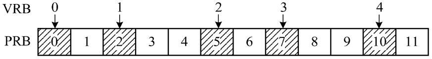
- FIG. 2a and FIG. 2b are schematic diagrams showing the allocation of resources to the UE by the base station, where the number M of the PRBs used for data transmission is 12, and the number N of the first PRBs corresponding to the first UE is 5, and
- the number S of the second PRB corresponding to the two UEs (referred to as the second PRB corresponding to the second VRB for the sake of understanding and differentiation) is 3. That is, 5 first PRBs and 3 second PRBs are to be determined from 12 PRBs. That is, as long as the PRB (including the first PRB and the second PRB) corresponding to the 8 VRBs (including the first VRB and the second VRB) is determined.
- 2a is a schematic diagram of a base station allocating resources for a first UE according to an embodiment of the invention.
- the sequence numbers of the PRBs and the VRBs are exactly the same, that is, the M PRB numbers are arranged in the first direction, specifically: 0, 1, 2, 3, ..., M-1.
- the base station may also select a part of the PRBs from the M PRBs for data transmission, for example, L, and L is a natural number smaller than M.
- the PRB numbers corresponding to the L PRBs may be: 0, 1, 2, 3, ..., L-1, or may also be: 3, 4, 5, ..., L+2, etc., the present invention is This is not particularly limited, and the L PRBs may be L consecutive or discontinuous PRBs among the M PRBs.
- L is equal to M, and M PRBs need to be described by sequentially arranging steps of 1 and 0 to M-1. It should be understood that L equals M is merely an illustrative description and should not be construed as limiting the invention.
- the first first PRB of the five first PRBs may be a PRB with a PRB sequence number of 0 in the M PRBs, that is, m takes a value of 0.
- the first step length W 1 corresponding to the first UE has a value range of [1, 11/4].
- the second to fifth first PRBs are determined according to the first step length and the PRB sequence number of the first first PRB.
- the PRB numbers of the PRBs corresponding to the five first PRBs in the M PRBs can be determined.
- the VRB is used to continuously carry data of each UE, that is, the VRB numbers of the first VRB corresponding to the first UE are: 0, 1, 2, 3, 4.
- the continuous VRBs are allocated to the discontinuous physical sub-bands. It should be understood that the rounding rounding process enumerated above is only an example of the rounding process, and the present invention should not be limited in any way. For example, the rounding process may also include rounding up or rounding down. The present invention is not particularly limited thereto.
- the base station may also select the last PRB of the M PRBs as the last PRB of the N first PRBs, or select the PRB in the intermediate position from the M PRBs as the first of the N first PRBs or The last PRB.
- the base station may select the PRB with the PRB sequence number 2 in FIG. 2a as the first first PRB of the N first PRBs.
- the comparison shows that when the value of m is 0 and the value of m is 2, the degree of dispersion of the N first PRBs in the M PRBs is different. When the value of m is 0, the degree of dispersion of the N first PRBs can be made larger.
- FIG. 2b is a schematic diagram of a base station allocating resources for a second UE according to an embodiment of the invention.
- Fig. 2b shows a case where seven PRBs are sequentially arranged in the first direction and the step size is 1.
- the second step size W 2 corresponding to the second UE has a value range of [1, 1 1/2].
- the second second PRB and the third second PRB are determined according to the second step and the PRB sequence number of the last second PRB.
- the VRB is used to continuously carry data of each UE, that is, the VRB numbers of the second VRB corresponding to the second UE are: 5, 6, and 7. Corresponding to the second PRB with the PRB sequence number of 1, 4, and 6 in the physical resource. Since the second step is introduced in the process of determining the second PRB, the continuous VRBs are allocated to the discontinuous physical sub-bands.
- the MNS (or the remaining MNS) PRBs other than the N first PRBs and the S second PRBs in the M PRBs can be further allocated to the first The three UEs, that is, allocate resources according to the number of PRBs corresponding to the third UE.
- the data to be transmitted of the same UE is evenly distributed into the physical resources, and the data of the channel fading to the single UE is reduced.
- the influence of the transmission so that the influence of the channel fading on the data transmission can be evenly distributed to the data transmission of the plurality of UEs, that is, the error rate of the signal is evenly distributed to the uplink data of the plurality of UEs, thereby each
- the error rate of the uplink data of the UE is within the range of error correction, and the error correction is performed by the existing error correction mechanism, thereby successfully decoding and finally improving.
- the purpose of transmission success is performed by the existing error correction mechanism, thereby successfully decoding and finally improving.
- the above example only considers the case where the number of VRBs used for data to be transmitted of each UE is small, specifically, the case where the number of first VRBs corresponding to the first UE is less than or equal to M/2.
- the number of the first VRBs is greater than M/2, even if the first PRBs are evenly allocated according to the step size, at least two first PRBs occupy at least two consecutive PRBs, and even more of the first PRBs occupy consecutive ones. The situation of the PRB.
- the PRB is still allocated according to the above method, and the channel fading occurs in a consecutive position of the plurality of first PRBs, the data to be transmitted of the first UE is affected, and the bit error rate of a certain data segment may occur. Particularly high situation.
- the frequency hopping here can be understood as follows: the virtual resources corresponding to the VRBs carried on two consecutive PRBs are discontinuous. That is, the data carried on two consecutive PRBs is discontinuous. That is to say, the original sequence of data to be transmitted is scrambled, so that the correlation of data carried on successive PRBs is weakened.
- the advantage of this is that the effect of channel degradation on data transmission can be dispersed into two non-adjacent data segments, becoming random errors.
- the essence is that the burst error of the signal is discretized, and the higher the discretization degree of the burst error code, the easier the system is to correct the error of the single error code distributed, and the more the protection ability of the burst error code Strong.
- the method 100 further includes:
- the mapping relationship between the L VRBs and the M PRBs is determined according to the preset minimum hopping distance, where the mapping relationship is used to indicate the position of each VRB in the L VRBs in the M PRBs, and the minimum hopping distance is specifically any two.
- the difference between the consecutive VRB sequence numbers corresponding to the VRB sequence numbers, the minimum hop distance is used to indicate the distance of the virtual sub-bands used by the VRBs corresponding to any two consecutive PRBs
- M is the number of PRBs available for data transmission.
- L is the number of VRBs used for data transmission;
- the VRB numbers of the N first VRBs corresponding to the PRB numbers of the N first PRBs are determined.
- the base station performs the frequency hopping process on the VRB, that is, the VRBs carried on the consecutive two PRBs are rearranged, so that the distance of the virtual sub-band corresponding to the VRBs carried on the adjacent two PRBs is greater than or Equal to the minimum frequency hopping distance.
- the specific expression may be that the difference between the sequence numbers of the VRBs carried on the two adjacent PRBs is greater than or equal to a preset value, and the preset value corresponds to the minimum frequency hopping distance.
- the VRB sequence that originally carries the same UE data is scrambled, that is, the data from the same UE is no longer carried by the continuous VRB. That is to say, the data carried by the two consecutive VRBs is discontinuous, or the correlation is small or not.
- the frequency hopping VRB is referred to as a frequency hopping VRB (Frequency-Hopping VRB, referred to as "FHVRB").
- FHVRB Frequency-Hopping VRB
- the FHVRB is also a VRB, and is only used as a FHVRB for distinguishing from a VRB that has not undergone frequency hopping processing in the prior art, and should not be construed as limiting the present invention.
- the present invention also does not exclude the case where the VRB is used after the frequency hopping process, or the case where another name is used.
- the frequency hopping process is implemented in the process of mapping the VRB to the PRB, so the VRB is not subjected to frequency hopping processing prior to mapping.
- the number M of PRBs and the number L of VRBs may be the same or different. Regardless of whether M and L are the same or different, the VRB can be mapped according to the following rules. The difference is that when M is greater than or equal to L, L VRBs can be mapped to M PRBs at one time; when M is less than L, L VRBs need to be mapped into PRBs at least twice, or in one mapping. Only part of the L VRBs (for example, up to M) VRBs can be mapped to M PRBs.
- the number of L is determined by the sum of the number of UEs that need to perform uplink data transmission in the current time unit and the number of VRBs corresponding to the UE.
- the number of Ls is a natural number greater than or equal to N+S.
- mapping relationship between the PRB and the FHVRB will be described in detail with reference to FIG. 3 taking M equal to L as an example.
- FIG. 3 is a schematic diagram of a mapping pattern between a PRB and a FHVRB according to another embodiment of the present invention.
- L PRBs whose PRB numbers are 0 to L-1 are in one-to-one correspondence with L FHVRBs. Specifically, when L is an odd number, the FHVRB numbers of the L FHVRBs are sequentially arranged in the order of 0 to L-1 according to the PRB number: 0, (L+1)/2, 1, (L+1)/2 +1,...,L-1,(L-1)/2, that is, the minimum hopping distance is (L-1)/2; when L is even, the FHVRB numbers of the L FHVRBs are from 0 to 0 according to the PRB number
- the order of L-1 is sequentially arranged as: 0, L/2, 1, L/2+1, ..., L/2-1, L, that is, the minimum frequency hopping distance is L/2-1.
- the FHVRB numbers of the L FHVRBs are sequentially arranged in the order of the step size of 1 and from 0 to (L-1)/2 in the position where the PRB number is even, and the PRB number is The odd-numbered positions are sequentially arranged in the order of (1) from (L+1)/2 to L.
- the FHVRB numbers of the L FHVRBs are in steps of the position where the PRB number is even. 1. Continually arranged in order from 0 to L/2-1, and sequentially arranged in the order of L/2 to L in the order of the number of the PRB numbers being odd.
- FIG. 4 is a schematic diagram of a mapping pattern between a PRB and a FHVRB according to still another embodiment of the present invention.
- the serial numbers of the 18 FHVRBs successively arranged on the 18 PRBs are: 0, 9, 1, 10, 2, 11, 3, 12, 4, 13, 5, 14, respectively. 6,15,7,16,8,17. It can be seen that among the above 18 FHVRB numbers, the difference between consecutive two FHVRB numbers is at least 8, that is, 18/2-1.
- mapping relationship between the FHVRB number and the PRB number listed herein is merely illustrative, and the present invention should not be limited in any way.
- the base station may allocate resources for the first FHVRB of the first UE and the second FHVRB of the second UE according to the foregoing resource allocation manner.
- FIG. 5 including FIGS. 5a to 5c
- FIG. 7 including FIGS. 7a and 7b.
- 5a to 5c are schematic diagrams of a base station allocating resources for a first UE, a second UE, and a third UE, respectively, according to another embodiment of the present invention.
- the number M of PRBs that can be used for data transmission is 12, and the mapping relationship between the FHVRB and the PRB is as shown in FIG. 3.
- the number N of the first FHVRBs corresponding to the first UE is 5, the number S of the second FHVRBs corresponding to the second UE is 3, and the number T of the fourth FHVRBs corresponding to the third UE is 2.
- FIG. 5a is a schematic diagram of a base station allocating resources for a first UE according to another embodiment of the present invention.
- positions are determined for the four first PRBs corresponding to the remaining four first VRBs.
- the PRB number of the second first PRB in the 12 PRBs is 2, and the PRB number of the third first PRB in the 12 PRBs is 5, the fourth The PRB number of a PRB in 12 PRBs is 7, and the PRB number of the fifth first PRB in 12 PRBs is 10.
- the first VRB here may be a FHVRB after frequency hopping processing or a VRB that has not undergone frequency hopping processing. That is to say, the frequency hopping process for the first VRB may be performed after the first PRB is determined, or may be performed before the first PRB is determined, or may be performed simultaneously with determining the first PRB, which is not limited by the present invention.
- the VRB sequence number of the first FHVRB used to carry the data to be transmitted of the first UE may be determined according to the mapping relationship between the FHVRB and the PRB, that is, the phase numbers of the PRB are 0, 2, 5, 7, and 10, respectively.
- the FHVRB sequence number of the corresponding FHVRB It can be determined from FIG. 3 that the FHVRB numbers of the first FHVRB are: 0, 1, 8, 9, and 5, respectively.
- FIG. 5b is a schematic diagram of a base station allocating resources for a second UE according to another embodiment of the present invention. As shown in FIG. 5b, the base station first renumbers the remaining 7 PRBs. As can be seen from the figure, the numbers are 0, 1, 2, 3, 4, 5, and 6 from left to right.
- the location is determined for the last second PRB corresponding to the last second VRB.
- the last PRB of the remaining 7 PRBs ie, the PRB with the PRB sequence number of 6 in the remaining 7 PRBs
- the positions are determined for the two second PRBs corresponding to the remaining two second VRBs.
- the PRB number of the second second PRB in the 7 PRBs is 4, and the PRB number of the first 2nd PRBs in the 7 PRBs is 1.
- the second VRB herein may be a FHVRB after frequency hopping processing or a VRB that has not undergone frequency hopping processing. That is to say, the frequency hopping process for the second VRB may be performed after the second PRB is determined, or may be performed before the second PRB is determined, or may be performed simultaneously with determining the second PRB, which is not limited by the present invention.
- the FHVRB sequence number of the second FHVRB for carrying the data to be transmitted of the second UE may be determined according to the mapping relationship between the FHVRB and the PRB, that is, the FHVRB corresponding to the PRB sequence numbers of 6, 4, 1, respectively.
- FHVRB serial number It can be determined from FIG. 3 that the FHVRB numbers of the second FHVRB are: 11, 4, and 7, respectively.
- FIG. 5c is a schematic diagram of a base station allocating resources for a third UE according to another embodiment of the present invention. As shown in FIG. 5c, the base station first renumbers the remaining 4 PRBs. As can be seen from the figure, the numbers are 0, 1, 2, and 3 from left to right.
- the third VRB the VRB corresponding to the third UE
- the third VRB the VRB corresponding to the third UE
- the third VRB will be The corresponding PRB is recorded as the third PRB) to determine the location.
- the first PRB of the four PRBs ie, the PRB with the PRB sequence number of 0 in the remaining four PRBs
- the first third PRB is taken as the first third PRB.
- the positions are determined for the two second PRBs corresponding to the remaining two third VRBs.
- the base station determines the PRB for the UE, and the PRB sequence number of the second third PRB in the four PRBs is 2.
- the third VRB herein may be a FHVRB after frequency hopping processing or a VRB that has not undergone frequency hopping processing. That is to say, the frequency hopping process for the third VRB may be performed after the third PRB is determined, or may be performed before the third PRB is determined, or may be performed simultaneously with determining the third PRB, which is not limited by the present invention.
- the VRB sequence number of the third FHVRB for carrying the data to be transmitted of the third UE may be determined according to the mapping relationship between the VRB and the PRB, that is, the FHVRB corresponding to the PRB sequence numbers of 6, 4, 1, respectively. VRB serial number. It can be determined from FIG. 3 that the VRB numbers of the third FHVRB are respectively 6,3.
- the location of the first PRB, the second PRB, and the third PRB allocated by the base station for the first UE, the second UE, and the third UE in the M PRBs, and the corresponding first FHVRB and second FHVRB may be determined.
- the FHVRB sequence number of the third VRB As can be seen from FIG. 5c, the first PRB, the second PRB, and the third PRB are equally allocated among the M PRBs, and any two of the first PRBs, the second PRBs, or the third PRBs do not continuously use the two PRBs. Resources.
- the present invention does not prioritize the frequency hopping process of the VRB (eg, the first VRB, the second VRB, and the third VRB) and the determination of the execution of the PRB (eg, the first PRB, the second PRB, and the third PRB). limited.
- the frequency hopping process is performed on the VRB of any multiple UEs.
- the present invention is also not limited to the order in which the PRBs corresponding to the respective UEs are executed.
- the present invention introduces the concept of the longest consecutive RBs from a single UE ("LCRB").
- the maximum number of contiguous resource blocks is used to indicate the number of contiguous resource blocks for physical resources of the same user within one time unit. In other words, the information of the same user is not very concentrated in a certain physical frequency band. What is the maximum number of consecutive resource blocks, which means how many consecutive physical sub-bands are used to carry the data to be transmitted of the same user. It can be seen that in the embodiment shown in Figure 5 (including Figures 5a, 5b and 5c), the maximum number of resource blocks is one.
- the first VRB is a VRB transmitted by the first UE in the first time unit
- the method 100 also includes:
- N first VRBs corresponding to the first UE for transmission in the second time unit wherein the N second VRBs are cyclically shifted by the N first VRBs, wherein the second time unit is the first The next time unit of the time unit.
- a VRB used by the same UE in one subframe ie, two adjacent slots
- the VRB number of the VRB ie, FHVRB
- the VRB number corresponding to the first VRB for the first UE in the first time unit eg, the first time slot
- the next time unit eg, the second time slot
- the VRB corresponding to the first UE is recorded as the first VRB
- the VRB corresponding to the second UE is recorded as the second VRB
- the VRB corresponding to the third UE is recorded as the third VRB
- the The PRB corresponding to one VRB is recorded as the first PRB
- the PRB corresponding to the second VRB is recorded as the second PRB
- the PRB corresponding to the third VRB is recorded as the third PRB.
- the VRB corresponding to the first UE is recorded as the fourth VRB
- the PRB corresponding to the fourth VRB is recorded as the fourth PRB.
- the N fourth VRBs are still used for data transmission by the first UE.
- the physical frequency bands used by the VRBs corresponding to the same UE are coincident without cyclic shift. Since channel fading is not limited to the frequency domain, it is also possible to continue fading in two consecutive time slots (for example, the first time slot and the second time slot) if channel fading occurs in a certain sub-band within the first time slot. The data carried by the physical sub-band will be affected. If the data of the same UE is still carried in the same sub-band of the next time slot (ie, the second time slot), the data of the UE will be affected. The serious impact makes the bit error rate increase.
- the two VRBs of the same VRB sequence do not overlap in the physical subbands corresponding to the first time slot and the second time slot, that is, to a certain extent.
- the effect of channel fading on data transmission in the time domain direction is alleviated.
- time slots recited herein are merely examples of time units and are merely illustrative and should not be construed as limiting the invention.
- This time unit can also be other units for characterizing time. As long as two consecutive time units or more time units are used for data transmission of the same UE, and the VRB number used by the UE on consecutive time units does not change, it falls within the protection scope of the present invention.
- N third VRBs corresponding to the first UE listed in the second time unit are merely exemplary and should not be construed as limiting the invention.
- the second UE has S second VRBs in the first time unit and S fifth VRBs in the second time unit, and the third UE has T numbers in the first time unit.
- the three VRBs have T sixth VRBs in the second time unit.
- FIG. 6 is a schematic illustration of a cyclic shift in accordance with another embodiment of the present invention.
- the VRB serial numbers of the VRBs corresponding to the 12 PRBs are marked on the corresponding PRBs.
- the VRB number of the VRB corresponding to the 12 PRBs in the first time slot is as shown in FIG. 3, and in the second time slot, the VRB is cyclically shifted to the left by one PRB, as shown in FIG. 6.
- the resource usage shown in It can be seen that at least one PRB is occupied by the VRB carrying the data in different physical sub-bands and different time slots.
- the amount of displacement of the cyclic shift may be one PRB or two PRBs, and the direction of the cyclic shift may be the first direction or the second direction, which is not limited by the present invention.
- the present invention introduces the concept of a diversity order (Diviersity Order).
- the order of diversity can be understood as how many sub-bands are occupied by data from the same user in two time slots of a sub-frame.
- the present invention introduces the concept of diversity order, maximum number of consecutive resource blocks, and minimum frequency hopping distance.
- FIG. 6 how to determine the above three indicators will be described in detail.
- the FHVRB numbers corresponding to the five first FHVRBs corresponding to the first UE are: 0, 1, 8, 9, and 5; respectively, and three corresponding to the second UE.
- the FHVRB numbers corresponding to the second FHVRB are: 11, 4, 1 respectively; and the FHVRB numbers corresponding to the two third FHVRBs corresponding to the third UE are respectively 6,3.
- the FHVRB corresponding to the first UE (including the first FHVRB and fourth FHVRB) have a total of 10 PRBs occupied by the first time slot and the second time slot; FHVRBs (including the second FHVRB and the fifth FHVRB) corresponding to the second UE are in the first time slot and the second time slot There are a total of six PRBs occupied by the time slots; the FHV RBs (including the third FHVRB and the sixth FHVRB) corresponding to the third UE have a total of four PRBs occupied by the first time slot and the second time slot. That is, the order of diversity of the first UE is 10, the order of diversity of the second UE is 6, and the order of diversity of the third UE is 4.
- the maximum number of consecutive resource blocks is determined.
- the first PRB corresponding to the five first FHVRBs corresponding to the first UE is not consecutive in 12 PRBs; the third second corresponding to the second UE The second PRB corresponding to the FHVRB is also not consecutive in the 12 PRBs; the third PRB corresponding to the two second FHVRBs corresponding to the third UE is also not consecutive in the 12 PRBs. That is, in the first time slot, the maximum number of consecutive resource blocks of the first UE is 1, the maximum number of consecutive resource blocks of the second UE is 1, and the maximum number of consecutive resource blocks of the third UE is 1. Similarly, in the second time slot, the maximum number of consecutive resource blocks of the first UE is also 1, the maximum number of consecutive resource blocks of the second UE is also 1, and the maximum number of consecutive resource blocks of the third UE is also 1.
- the minimum frequency hopping distance is determined. It should be noted here that the minimum frequency hopping distance is independent of the user and only relates to the mapping relationship between the FHVRB and the PRB. It can be seen that the minimum hopping distance of the FHVRB carried by the PRB shown in FIG. 6 is 5.
- data of multiple UEs can be evenly allocated to physical resources, so that the consecutive PRBs are carried.
- the correlation of the data is weakened, so that the channel fading is dispersed into the data of each UE, and the burst error of the signal is discretized.
- the number of FHVRBs corresponding to each UE is less than half of the number of PRBs to be allocated, so that two consecutive PRBs are not used for the same UE.
- the situation a case where the number of FHVRBs corresponding to the UE is large will be described in detail with reference to FIGS. 7a and 7b.
- FIG. 7a and 7b are schematic diagrams of a base station allocating resources for a first UE and a second UE, respectively, according to still another embodiment of the present invention.
- the number of PRBs that can be used for data transmission is 18, FHVRB
- the mapping relationship with the PRB is as shown in FIG.
- the number N of the first FHVRBs corresponding to the first UE is 13, and the number S of the second FHVRBs corresponding to the second UE is 3.
- FIG. 7a is a schematic diagram of a base station allocating resources for a first UE according to still another embodiment of the present invention. As shown in Figure 7a.
- the base station first determines a location for the first first PRB corresponding to the first first VRB. For example, the first PRB of the 18 PRBs (ie, the PRB with the PRB sequence number of 0) is taken as the first first PRB.
- the position is determined for the 12 first PRBs corresponding to the remaining 12 first VRBs.
- the first VRB here may be a FHVRB after frequency hopping processing or a VRB that has not undergone frequency hopping processing. That is to say, the frequency hopping process for the first VRB may be performed after the first PRB is determined, or may be performed before the first PRB is determined, or may be performed simultaneously with determining the first PRB, which is not limited by the present invention.
- the FHVRB sequence number of the first FHVRB for carrying the data to be transmitted of the first UE may be determined according to the mapping relationship between the FHVRB and the PRB, that is, the number of the PRB is 0, 1, 3, 4, 6, respectively.
- FIG. 7b is a schematic diagram of a base station allocating resources for a second UE according to still another embodiment of the present invention. As shown in FIG. 7b, the base station first renumbers the remaining five PRBs. As can be seen from the figure, the numbers are 0, 1, 2, 3, 4 from left to right.
- the location is determined for the last second PRB corresponding to the last second VRB.
- the last PRB of the remaining 5 PRBs ie, the PRB with the PRB sequence number of 4 in the remaining 5 PRBs
- the last second PRB is taken as the last second PRB.
- the positions are determined for the two second PRBs corresponding to the remaining two second VRBs.
- the second VRB herein may be a FHVRB after frequency hopping processing or a VRB that has not undergone frequency hopping processing. That is to say, the frequency hopping process for the second VRB may be performed after the second PRB is determined, or may be performed before the second PRB is determined, or may be performed simultaneously with determining the second PRB, which is not limited by the present invention.
- the FHVRB sequence number of the second FHVRB used to carry the data to be transmitted of the second UE may be determined according to the mapping relationship between the FHVRB and the PRB, that is, the FHVRB corresponding to the PRB serial number of 4, 2, 1, respectively. FHVRB serial number. It can be determined from FIG. 4 that the VRB numbers of the second VRB are: 8, 13, and 11, respectively.
- the location of the first PRB and the second PRB allocated by the base station for the first UE and the second UE in the M PRBs, and the FHVRB sequence numbers of the corresponding first FHVRB and the second FHVRB may be determined.
- the first PRB and the second PRB are equally distributed among the M PRBs.
- the number of the first FHVRBs is larger than M/2, two or more PRBs are necessarily continuous.
- the minimum hopping distance is considered in the mapping between the FHVRB and the PRB, the difference between the serial numbers of the VRBs carried on the two consecutive PRBs is greater than or equal to the minimum hopping distance, that is, the two consecutive PRBs are carried.
- the VRBs are not contiguous. That is to say, even if the FHVRBs carried on two consecutive PRBs are FHVRBs of the same UE, the data carried by the two consecutive PRBs is discontinuous.
- the present invention does not limit the order of frequency hopping processing of VRBs (eg, first VRB and second VRB) and determining the execution of PRBs (eg, first PRBs and second PRBs). Meanwhile, the present invention is also not particularly limited in the case of performing frequency hopping processing on VRBs of any of a plurality of UEs and determining the order of execution of PRBs corresponding to the respective UEs.
- the first FHVRB is an FHVRB that is transmitted by the first UE in the first time unit
- the second FHVRB is an FHVRB that is transmitted by the second UE in the first time unit.
- the fourth FHVRB corresponding to the first UE and the fifth FHVRB corresponding to the second UE in the second time unit may be obtained.
- FIG. 8 is a schematic illustration of a cyclic shift in accordance with yet another embodiment of the present invention.
- the FHVRB sequence numbers of the FHVRBs corresponding to the 18 PRBs are marked on the corresponding PRBs.
- the FHVRB number of the FHVRB corresponding to the 18 PRBs in the first time slot is as shown in FIG. 4, and the FHVRB is cyclically shifted to the left by one PRB in the second time slot, as shown in FIG. 8.
- the resource usage shown in It can be seen that at least one PRB is occupied by the FHVRB carrying the data in different physical subbands and different time slots.
- the amount of displacement of the cyclic shift may be one PRB or two PRBs, and the direction of the cyclic shift may be the first direction or the second direction, which is not limited by the present invention.
- the FHVRB numbers corresponding to the 13 first FHVRBs corresponding to the first UE are: 0, 1, 3, 4, 6, 7, 8, 10, 11, respectively. 12, 14, 15, 17; the FHVRB numbers corresponding to the three second FHVRBs corresponding to the second UE are: 8, 13, and 11, respectively.
- the VRBs corresponding to the first UE (including the first FHVRB and the fourth FHVRB) have a total of 18 PRBs occupied by the first time slot and the second time slot;
- the FHVRB corresponding to the UE (including the second FHVRB and the fifth FHVRB) has a total of six PRBs occupied by the first time slot and the second time slot. That is, the order of diversity of the first UE is 18, and the order of diversity of the second UE is 6.
- the maximum number of consecutive resource blocks is determined.
- the first consecutive PRBs corresponding to the first first FHV RBs corresponding to the first UE are the largest consecutive resource blocks among the 18, and the third corresponding to the second UE.
- the second PRB corresponding to the two FHVRBs is not continuous among the 18 PRBs. That is, in the first time slot, the maximum number of consecutive resource blocks of the first UE is 3, and the maximum number of consecutive resource blocks of the second UE is 1. Similarly, in the second time slot, the maximum number of consecutive resource blocks of the first UE is also 3, and the maximum number of consecutive resource blocks of the second UE is also 1.
- the minimum frequency hopping distance is determined. It can be seen that the minimum hopping distance of the FHVRB carried by the PRB shown in FIG. 8 is 8. Therefore, for the first UE, even if the maximum number of consecutive resource blocks is 3, the data carried in the consecutive PRBs is discontinuous, and the channel fading can be mitigated to a certain extent in a certain frequency band. The impact of the data carried by the PRB.
- data of multiple UEs can be evenly allocated to physical resources, so that the consecutive PRBs are carried.
- the correlation of the data is weakened, so that the channel fading is dispersed into the data of each UE, and the burst error of the signal is discretized.
- the VRB is allocated according to the UE, the step size of the corresponding PRB is determined according to the number of VRBs, and the position of the corresponding PRB in the physical resource is determined according to the step size.
- the data of each UE can be evenly distributed in a given physical resource, so that the number of consecutive resource blocks corresponding to each UE is minimized, and the influence of channel fading on data transmission is reduced.
- the mapping pattern of the VRB and the PRB is determined, so that the correlation of the data carried on the continuous PRB is weakened, and the influence of the channel fading on the data transmission is also alleviated.
- the order of diversity of the same user is increased, which is more advantageous for diversity gain.
- FIG. 9 is a schematic flow diagram of a method 200 for data transmission in accordance with yet another embodiment of the present invention.
- the method shown in FIG. 9 may be performed by a base station or by a network device, and the present invention is not particularly limited thereto.
- FIG. 9 illustrates a detailed communication step or operation of a method for data transmission according to still another embodiment of the present invention from the perspective of a base station, but these steps or operations are merely examples, and embodiments of the present invention may also be performed. Other operations or variations of the various operations in FIG.
- the various steps in FIG. 9 may be performed in a different order than that presented in FIG. 9, and it is possible that not all operations in FIG. 9 are to be performed.
- the method 200 includes:
- mapping relationship between the L VRBs and the M PRBs according to the preset minimum hopping distance, where the mapping relationship is used to indicate the position of each VRB in the L VRBs in the M PRBs, and the minimum hopping distance is specifically The difference between the VRB sequence numbers corresponding to two consecutive PRB sequence numbers, and the minimum frequency hopping distance is used to indicate the distance of the virtual sub-band used by the VRB corresponding to any two consecutive PRBs, where M is available for data transmission.
- the number of PRBs, L is the number of VRBs used for data transmission
- M PRBs correspond to M physical sub-bands for data transmission
- L VRBs correspond to L virtual sub-bands for data transmission;
- S220 Determine N first PRBs corresponding to the first user equipment UE, where the N first PRBs correspond to N physical sub-bands for carrying data to be transmitted of the first UE, where N is greater than or equal to 1. Natural number;
- S230 Determine, according to the mapping relationship and the N first PRBs, N first VRBs corresponding to the N first PRBs, where the N first VRBs are associated with N virtual subbands for carrying data to be transmitted. correspond.
- the base station may perform frequency hopping processing on the VRB before the resource is allocated to the UE, or when the resource is allocated to the UE, that is, the VRB is mapped to the PRB according to the preset minimum hop distance, so that two adjacent two The distance of the virtual sub-band corresponding to the VRB carried on the PRB is greater than or equal to the minimum frequency hopping distance.
- the frequency hopping VRB is recorded as a frequency hopping VRB.
- the correlation of the data carried on the adjacent PRB is weakened, and the influence of the channel weakening on the data transmission can be dispersed to no.
- the adjacent two data segments it becomes a random error. Therefore, the burst error of the signal is discretized, which is more favorable for the system to perform error correction processing on the single error code of the scattered distribution, thereby further improving the transmission success rate.
- FIG. 10 is a schematic block diagram of an apparatus 300 for data transmission, in accordance with an embodiment of the present invention. As shown in FIG. 10, the apparatus 300 includes a first determining unit 310, a second determining unit 320, and a third determining unit 330.
- the first determining unit 310 is configured to determine the number N of the first virtual resource blocks VRB corresponding to the first user equipment UE, and the N first VRBs and the N virtual to be used to carry the data of the first UE to be transmitted.
- the sub-band corresponds, and N is a natural number greater than or equal to 1;
- the second determining unit 320 is configured to determine, according to the number N of the first VRBs, a first step length corresponding to the N first VRBs, where the first step length is used to indicate that the N first VRBs are mapped to adjacent ones of the physical resources.
- the distance between two physical sub-bands, the first step length is greater than 1;
- the third determining unit 330 is configured to determine, according to the first step length, corresponding to the N first VRBs. N first PRBs, N first PRBs corresponding to N physical sub-bands for carrying data to be transmitted.
- the apparatus 300 for data transmission according to an embodiment of the present invention may correspond to a base station in a method for data transmission according to an embodiment of the present invention, and each module in the apparatus 300 and the other operations and/or functions described above are respectively In order to implement the corresponding process of the method in FIG. 1, for brevity, no further details are provided herein.
- the apparatus for data transmission determines the first step length of the corresponding first PRB in the physical resource according to the number of the first VRB corresponding to the first UE, and the first step is long. If the value is greater than 1, the first PRB that is used to carry the data to be transmitted is determined, so that the distance between the at least two adjacent first PRBs that are mapped to the physical resource is greater than 1, so that the data to be transmitted of the first UE is dispersed to the physical resource. In the process, the effect of channel fading on data transmission is reduced, and the transmission success rate is improved.
- FIG. 11 is a schematic block diagram of an apparatus 400 for data transmission in accordance with another embodiment of the present invention. As shown in FIG. 11, the apparatus 400 includes a first determining unit 410, a second determining unit 420, and a third determining unit 430.
- the first determining unit 410 is configured to determine, according to the preset minimum hopping distance, a mapping relationship between the L virtual resource blocks VRB and the M physical resource blocks PRB, where the mapping relationship is used to indicate each VRB of the L VRBs.
- the minimum hopping distance is specifically the difference of the VRB numbers corresponding to any two consecutive PRB numbers, and the minimum hopping distance is used to indicate the VRBs corresponding to any two consecutive PRBs.
- the distance of the virtual sub-band where M is the number of PRBs available for data transmission, L is the number of VRBs used for data transmission, L VRBs correspond to L virtual sub-bands used for data transmission, M PRBs Corresponding to M physical subbands used for data transmission;
- the second determining unit 420 is configured to determine N first PRBs corresponding to the first user equipment UE, where the N first PRBs correspond to N physical sub-bands for carrying data to be transmitted of the first UE, where N is a natural number greater than or equal to 1;
- the third determining unit 430 is configured to determine, according to the mapping relationship and the N first PRBs, N first VRBs corresponding to the N first PRBs, and the N first VRBs and the N used to carry data to be transmitted.
- the virtual sub-band corresponds.
- the apparatus 400 for data transmission according to an embodiment of the present invention may correspond to a base station in a method for data transmission according to an embodiment of the present invention, and each module in the apparatus 400 and the above
- the operation and/or function of the operation are respectively implemented in order to implement the corresponding process of the method in FIG. 9, and for brevity, no further details are provided herein.
- the apparatus for data transmission by performing frequency hopping processing on the VRB, so that the correlation of the data carried on the adjacent PRB is weakened, and the influence of the channel weakening on the data transmission can be dispersed to no In the adjacent two data segments, it becomes a random error. Therefore, the burst error of the signal is discretized, which is more favorable for the system to perform error correction processing on the single error code of the scattered distribution, thereby further improving the transmission success rate.
- FIG. 12 is a schematic block diagram of an apparatus 500 for data transmission, in accordance with an embodiment of the present invention.
- the device 500 includes a transceiver 510, a processor 520, a memory 530, and a bus system 540.
- the transceiver 510, the processor 520, and the memory 530 are connected by a bus system 540 for storing instructions.
- the processor 520 is configured to execute instructions stored by the memory 530 to control the transceiver 510 to send and receive signals.
- the processor 520 is configured to determine the number N of the first virtual resource blocks VRB corresponding to the first user equipment UE, and the N first VRBs and the N virtual sub-bands of the data to be transmitted used to carry the first UE.
- N is a natural number greater than or equal to 1;
- the processor 520 is further configured to determine, according to the number N of the first VRBs, a first step length corresponding to the N first VRBs, where the first step length is used to indicate that the N first VRBs are mapped to the adjacent two of the physical resources.
- the processor 520 is further configured to determine, according to the first step, N first PRBs corresponding to the N first VRBs, where the N first PRBs correspond to N physical sub-bands for carrying data to be transmitted.
- the processor 520 may be a central processing unit ("CPU"), and the processor 520 may also be other general-purpose processors, digital signal processors (DSPs). , an application specific integrated circuit (ASIC), an off-the-shelf programmable gate array (FPGA) or other programmable logic device, discrete gate or transistor logic device, discrete hardware component, and the like.
- the general purpose processor may be a microprocessor or the processor or any conventional processor or the like.
- the processor 520 can include read only memory and random access memory and provides instructions and data to the processor 520.
- a portion of processor 520 may also include a non-volatile random access memory.
- processor 520 can also store information of the type of device.
- the bus system 540 may include a power bus, a control bus, a status signal bus, and the like in addition to the data bus. However, for clarity of description, various buses are labeled as bus system 540 in the figure.
- each step of the foregoing method may be completed by an integrated logic circuit of hardware in the processor 520 or an instruction in a form of software.
- the steps of the positioning method disclosed in the embodiments of the present invention may be directly implemented as hardware processor execution completion, or performed by a combination of hardware and software modules in the processor.
- the software module can be located in a conventional storage medium such as random access memory, flash memory, read only memory, programmable read only memory or electrically erasable programmable memory, registers, and the like.
- the storage medium is located in the memory 530, and the processor 520 reads the information in the memory 530 and performs the steps of the above method in combination with its hardware. To avoid repetition, it will not be described in detail here.
- the apparatus 500 for data transmission according to an embodiment of the present invention may correspond to a base station in a method for data transmission according to an embodiment of the present invention, and each module in the apparatus 500 and the other operations and/or functions described above are respectively In order to implement the corresponding process of the method in FIG. 1, for brevity, no further details are provided herein.
- the device for data transmission determines the first step length of the corresponding first PRB in the physical resource according to the number of the first VRB corresponding to the first UE, and the first step is long. If the value is greater than 1, the first PRB that is used to carry the data to be transmitted is determined, so that the distance between the at least two adjacent first PRBs that are mapped to the physical resource is greater than 1, so that the data to be transmitted of the first UE is dispersed to the physical resource. In the process, the effect of channel fading on data transmission is reduced, and the transmission success rate is improved.
- FIG. 13 is a schematic block diagram of an apparatus 600 for data transmission in accordance with another embodiment of the present invention.
- the device 600 includes a transceiver 610, a processor 620, a memory 630, and a bus system 640.
- the transceiver 610, the processor 620, and the memory 630 are connected by a bus system 640 for storing instructions.
- the processor 620 is configured to execute instructions stored by the memory 630 to control the transceiver 610 to send and receive signals.
- the processor 620 is configured to determine, according to a preset minimum hopping distance, a mapping relationship between the L virtual resource blocks VRB and the M physical resource blocks PRB, where the mapping relationship is used to indicate that each of the L VRBs is in the M
- the position in the PRB, the minimum hopping distance is specifically the difference between the VRB numbers corresponding to any two consecutive PRB numbers, and the minimum hop distance is used to indicate the virtual sub-VID used by any two consecutive PRBs.
- the distance of the frequency band where M is the number of PRBs available for data transmission, L is the number of VRBs used for data transmission, and L VRBs are used for the number Corresponding to the L virtual sub-bands transmitted, M PRBs correspond to M physical sub-bands used for data transmission;
- the processor 620 is further configured to determine N first PRBs corresponding to the first user equipment UE, where the N first PRBs correspond to N physical sub-bands of the data to be transmitted used to carry the first UE, where N is greater than Or a natural number equal to 1;
- the processor 620 is further configured to determine, according to the mapping relationship and the N first PRBs, the N first VRBs corresponding to the N first PRBs, and the N first VRBs and the N virtual hosts that are used to carry the data to be transmitted.
- the sub-band corresponds.
- the apparatus 600 for data transmission according to an embodiment of the present invention may correspond to a base station in a method for data transmission according to an embodiment of the present invention, and each module in the apparatus 600 and the other operations and/or functions described above are respectively In order to implement the corresponding process of the method in FIG. 9, for brevity, no further details are provided herein.
- the device for data transmission can perform the frequency hopping process on the VRB so that the correlation of the data carried on the adjacent PRB is weakened, and the influence of the channel weakening on the data transmission can be dispersed to no. In the adjacent two data segments, it becomes a random error. Therefore, the burst error of the signal is discretized, which is more favorable for the system to perform error correction processing on the single error code of the scattered distribution, thereby further improving the transmission success rate.
- the size of the sequence numbers of the above processes does not mean the order of execution, and the order of execution of each process should be determined by its function and internal logic, and should not be taken to the embodiments of the present invention.
- the implementation process constitutes any limitation.
- the disclosed systems, devices, and methods may be implemented in other manners.
- the device embodiments described above are merely illustrative.
- the division of the unit is only a logical function division, and may be implemented in actual implementation.
- multiple units or components may be combined or integrated into another system, or some features may be omitted or not performed.
- the mutual coupling or direct coupling or communication connection shown or discussed may be an indirect coupling or communication connection through some interface, device or unit, and may be in an electrical, mechanical or other form.
- the units described as separate components may or may not be physically separated, and the components displayed as units may or may not be physical units, that is, may be located in one place, or may be distributed to multiple network units. Some or all of the units may be selected according to actual needs to achieve the purpose of the solution of the embodiment.
- each functional unit in each embodiment of the present invention may be integrated into one processing unit, or each unit may exist physically separately, or two or more units may be integrated into one unit.
- the functions may be stored in a computer readable storage medium if implemented in the form of a software functional unit and sold or used as a standalone product.
- the technical solution of the present invention which is essential or contributes to the prior art, or a part of the technical solution, may be embodied in the form of a software product, which is stored in a storage medium, including
- the instructions are used to cause a computer device (which may be a personal computer, server, or network device, etc.) to perform all or part of the steps of the methods described in various embodiments of the present invention.
- the foregoing storage medium includes: a U disk, a mobile hard disk, a read-only memory (RAM), a random access memory (ROM), a magnetic disk, or an optical disk, and the like, which can store program codes. .
Landscapes
- Engineering & Computer Science (AREA)
- Signal Processing (AREA)
- Computer Networks & Wireless Communication (AREA)
- Quality & Reliability (AREA)
- Mobile Radio Communication Systems (AREA)
Abstract
L'invention concerne un procédé et un dispositif de transmission de données, susceptibles de réduire l'influence de l'évanouissement de canaux sur la transmission de données et d'améliorer le taux de réussite de la transmission. Le procédé comporte les étapes consistant à: déterminer le nombre N de premiers blocs de ressources virtuels (VRB) correspondant à un premier équipement d'utilisateur (UE), les N premiers VRB correspondant à N sous-bandes virtuelles servant à transporter des données à transmettre du premier UE, et N étant un entier naturel supérieur ou égal à 1; déterminer une première longueur de pas correspondant aux N premiers VRB d'après le nombre N de premiers VRB, la première longueur de pas étant utilisée pour indiquer une distance de deux sous-bandes physiques adjacentes des N premiers VRB s'associant à une ressource physique, et la première longueur de pas étant supérieure à 1; et déterminer N premiers PRB correspondant aux N premiers VRB d'après la première longueur de pas, les N premiers PRB correspondant à N sous-bandes physiques servant à transporter les données à transmettre.
Priority Applications (4)
| Application Number | Priority Date | Filing Date | Title |
|---|---|---|---|
| CN201680084748.1A CN109076046B (zh) | 2016-05-25 | 2016-05-25 | 用于数据传输的方法和装置 |
| EP16902670.5A EP3454515B1 (fr) | 2016-05-25 | 2016-05-25 | Procédé de transmission de données |
| PCT/CN2016/083235 WO2017201680A1 (fr) | 2016-05-25 | 2016-05-25 | Procédé et dispositif de transmission de données |
| US16/303,690 US11019626B2 (en) | 2016-05-25 | 2016-05-25 | Allocating virtual resource blocks |
Applications Claiming Priority (1)
| Application Number | Priority Date | Filing Date | Title |
|---|---|---|---|
| PCT/CN2016/083235 WO2017201680A1 (fr) | 2016-05-25 | 2016-05-25 | Procédé et dispositif de transmission de données |
Publications (1)
| Publication Number | Publication Date |
|---|---|
| WO2017201680A1 true WO2017201680A1 (fr) | 2017-11-30 |
Family
ID=60411027
Family Applications (1)
| Application Number | Title | Priority Date | Filing Date |
|---|---|---|---|
| PCT/CN2016/083235 WO2017201680A1 (fr) | 2016-05-25 | 2016-05-25 | Procédé et dispositif de transmission de données |
Country Status (4)
| Country | Link |
|---|---|
| US (1) | US11019626B2 (fr) |
| EP (1) | EP3454515B1 (fr) |
| CN (1) | CN109076046B (fr) |
| WO (1) | WO2017201680A1 (fr) |
Families Citing this family (1)
| Publication number | Priority date | Publication date | Assignee | Title |
|---|---|---|---|---|
| CN111083726B (zh) * | 2019-07-15 | 2024-05-03 | 中兴通讯股份有限公司 | 传输功率确定方法及装置 |
Citations (3)
| Publication number | Priority date | Publication date | Assignee | Title |
|---|---|---|---|---|
| CN101039297A (zh) * | 2006-03-17 | 2007-09-19 | 北京三星通信技术研究有限公司 | 虚拟资源块到物理资源块的映射方法及系统 |
| CN101779432A (zh) * | 2007-08-13 | 2010-07-14 | 高通股份有限公司 | 无线通信系统中的频率多样化传输 |
| US20120163310A1 (en) * | 2010-12-23 | 2012-06-28 | Electronics And Telecommunications Research Institute | Apparatus for allocating physical resources |
Family Cites Families (13)
| Publication number | Priority date | Publication date | Assignee | Title |
|---|---|---|---|---|
| EP0573417B1 (fr) | 1990-02-27 | 1997-05-02 | Motorola, Inc. | Sauts entre frequences porteuses partagees |
| CN101146317A (zh) | 2006-09-15 | 2008-03-19 | 北京三星通信技术研究有限公司 | 资源分配及控制信令传输方法 |
| CN101170526A (zh) * | 2006-10-24 | 2008-04-30 | 华为技术有限公司 | 分布式子载波映射到物理资源块的方法、网络侧设备及用户终端 |
| EP1944896A1 (fr) * | 2007-01-09 | 2008-07-16 | Matsushita Electric Industrial Co., Ltd. | Configuration de canaux de contrôle dans un système de communication mobile |
| KR100913099B1 (ko) | 2008-01-07 | 2009-08-21 | 엘지전자 주식회사 | 분산형 가상자원블록 스케쥴링 방법 |
| EP2241019A4 (fr) * | 2008-01-09 | 2017-01-18 | Apple Inc. | Mise en correspondance d'indices de blocs de ressources distribués avec des blocs de ressources physiques |
| GB2457242A (en) | 2008-02-05 | 2009-08-12 | Nec Corp | Resource allocation in a communication system |
| CN101778394B (zh) * | 2009-01-12 | 2013-04-24 | 电信科学技术研究院 | 一种实现资源映射的方法和装置 |
| AU2011210153B2 (en) | 2010-01-26 | 2014-12-18 | Lg Electronics Inc. | Method and apparatus for allocating resources in a wireless communication system |
| KR101868622B1 (ko) | 2010-06-17 | 2018-06-18 | 엘지전자 주식회사 | R-pdcch 전송 및 수신 방법과 그 장치 |
| EP2437422A1 (fr) * | 2010-10-01 | 2012-04-04 | Panasonic Corporation | Espace de recherche pour liaison montante et descendante dans un système de communication mobile OFDM |
| CN106658732B (zh) * | 2011-08-15 | 2020-04-14 | 华为技术有限公司 | 控制信道资源的分配方法及装置 |
| CN105338518B (zh) | 2014-07-31 | 2020-03-31 | 索尼公司 | 无线通信系统中的装置和方法 |
-
2016
- 2016-05-25 WO PCT/CN2016/083235 patent/WO2017201680A1/fr unknown
- 2016-05-25 EP EP16902670.5A patent/EP3454515B1/fr active Active
- 2016-05-25 CN CN201680084748.1A patent/CN109076046B/zh active Active
- 2016-05-25 US US16/303,690 patent/US11019626B2/en active Active
Patent Citations (3)
| Publication number | Priority date | Publication date | Assignee | Title |
|---|---|---|---|---|
| CN101039297A (zh) * | 2006-03-17 | 2007-09-19 | 北京三星通信技术研究有限公司 | 虚拟资源块到物理资源块的映射方法及系统 |
| CN101779432A (zh) * | 2007-08-13 | 2010-07-14 | 高通股份有限公司 | 无线通信系统中的频率多样化传输 |
| US20120163310A1 (en) * | 2010-12-23 | 2012-06-28 | Electronics And Telecommunications Research Institute | Apparatus for allocating physical resources |
Non-Patent Citations (1)
| Title |
|---|
| See also references of EP3454515A4 * |
Also Published As
| Publication number | Publication date |
|---|---|
| US20200322952A1 (en) | 2020-10-08 |
| EP3454515A4 (fr) | 2019-05-22 |
| CN109076046B (zh) | 2020-07-24 |
| EP3454515A1 (fr) | 2019-03-13 |
| CN109076046A (zh) | 2018-12-21 |
| US11019626B2 (en) | 2021-05-25 |
| EP3454515B1 (fr) | 2020-05-13 |
Similar Documents
| Publication | Publication Date | Title |
|---|---|---|
| US11457443B2 (en) | Method for transmitting configuration information and terminal device | |
| JP6784426B2 (ja) | データ処理方法、基地局および端末 | |
| WO2019137455A1 (fr) | Procédé de configuration de ressource, et appareil de communication | |
| US20130107867A1 (en) | Reducing In-Device Interference Between Multiple Wireless Communications of a Multi-Mode Mobile Device | |
| WO2018059173A1 (fr) | Procédé de transmission d'informations de liaison montante sans licence, dispositif de réseau et dispositif terminal | |
| CN111294971B (zh) | 用于信道传输的方法、终端设备及网络设备 | |
| CN108631816B (zh) | 发送数据的方法和装置,以及接收数据的方法和装置 | |
| JP6678743B2 (ja) | 通信方法、端末デバイス及びネットワークデバイス | |
| US20190342893A1 (en) | Data Packet Transmission Method and Terminal | |
| US11224037B2 (en) | Data transmission method, terminal device, and network device | |
| CN109548149B (zh) | 一种rbg的划分方法和用户终端 | |
| CN111769899B (zh) | 确定传输资源的方法及装置 | |
| CN111770577A (zh) | 确定传输资源的方法及装置 | |
| KR20210025589A (ko) | 차량 인터넷에서의 데이터 전송 방법 및 단말기 디바이스 | |
| CN111436136A (zh) | 免授权传输的方法及装置 | |
| US20220149987A1 (en) | Method for sidelink rate matching and resource mapping, and device | |
| WO2015021623A1 (fr) | Procédé et dispositif de sélection de porteuses multiples | |
| CN115104277B (zh) | 用于无线通信中的多分量载波物理下行链路共享信道调度的方法和装置 | |
| WO2017201680A1 (fr) | Procédé et dispositif de transmission de données | |
| JP2019519950A (ja) | 装置間(d2d)通信方法及びd2d装置 | |
| CN113038610B (zh) | 数据传输方法、装置、设备、存储介质以及程序产品 | |
| CN112583528B (zh) | 确定传输块大小的方法和装置 | |
| CN110383913B (zh) | 资源的分配方法、确定方法和装置 | |
| CN113383590B (zh) | 通信方法和通信设备 | |
| CN113826342B (zh) | 一种通信方法及相关设备 |
Legal Events
| Date | Code | Title | Description |
|---|---|---|---|
| NENP | Non-entry into the national phase |
Ref country code: DE |
|
| 121 | Ep: the epo has been informed by wipo that ep was designated in this application |
Ref document number: 16902670 Country of ref document: EP Kind code of ref document: A1 |
|
| ENP | Entry into the national phase |
Ref document number: 2016902670 Country of ref document: EP Effective date: 20181205 |