WO2017200005A1 - Laser cutting and machining method for plated steel plate, laser cut-and-machined product, thermal cutting and machining method, thermal cut-and-machined product, surface-treated steel plate, laser cutting method, and laser machining head - Google Patents
Laser cutting and machining method for plated steel plate, laser cut-and-machined product, thermal cutting and machining method, thermal cut-and-machined product, surface-treated steel plate, laser cutting method, and laser machining head Download PDFInfo
- Publication number
- WO2017200005A1 WO2017200005A1 PCT/JP2017/018528 JP2017018528W WO2017200005A1 WO 2017200005 A1 WO2017200005 A1 WO 2017200005A1 JP 2017018528 W JP2017018528 W JP 2017018528W WO 2017200005 A1 WO2017200005 A1 WO 2017200005A1
- Authority
- WO
- WIPO (PCT)
- Prior art keywords
- cutting
- steel sheet
- laser
- cut
- plating
- Prior art date
Links
Images


Classifications
-
- B—PERFORMING OPERATIONS; TRANSPORTING
- B23—MACHINE TOOLS; METAL-WORKING NOT OTHERWISE PROVIDED FOR
- B23K—SOLDERING OR UNSOLDERING; WELDING; CLADDING OR PLATING BY SOLDERING OR WELDING; CUTTING BY APPLYING HEAT LOCALLY, e.g. FLAME CUTTING; WORKING BY LASER BEAM
- B23K26/00—Working by laser beam, e.g. welding, cutting or boring
- B23K26/36—Removing material
- B23K26/38—Removing material by boring or cutting
-
- B—PERFORMING OPERATIONS; TRANSPORTING
- B23—MACHINE TOOLS; METAL-WORKING NOT OTHERWISE PROVIDED FOR
- B23K—SOLDERING OR UNSOLDERING; WELDING; CLADDING OR PLATING BY SOLDERING OR WELDING; CUTTING BY APPLYING HEAT LOCALLY, e.g. FLAME CUTTING; WORKING BY LASER BEAM
- B23K26/00—Working by laser beam, e.g. welding, cutting or boring
- B23K26/02—Positioning or observing the workpiece, e.g. with respect to the point of impact; Aligning, aiming or focusing the laser beam
- B23K26/04—Automatically aligning, aiming or focusing the laser beam, e.g. using the back-scattered light
- B23K26/046—Automatically focusing the laser beam
-
- B—PERFORMING OPERATIONS; TRANSPORTING
- B23—MACHINE TOOLS; METAL-WORKING NOT OTHERWISE PROVIDED FOR
- B23K—SOLDERING OR UNSOLDERING; WELDING; CLADDING OR PLATING BY SOLDERING OR WELDING; CUTTING BY APPLYING HEAT LOCALLY, e.g. FLAME CUTTING; WORKING BY LASER BEAM
- B23K26/00—Working by laser beam, e.g. welding, cutting or boring
- B23K26/08—Devices involving relative movement between laser beam and workpiece
- B23K26/083—Devices involving movement of the workpiece in at least one axial direction
- B23K26/0853—Devices involving movement of the workpiece in at least in two axial directions, e.g. in a plane
-
- B—PERFORMING OPERATIONS; TRANSPORTING
- B23—MACHINE TOOLS; METAL-WORKING NOT OTHERWISE PROVIDED FOR
- B23K—SOLDERING OR UNSOLDERING; WELDING; CLADDING OR PLATING BY SOLDERING OR WELDING; CUTTING BY APPLYING HEAT LOCALLY, e.g. FLAME CUTTING; WORKING BY LASER BEAM
- B23K26/00—Working by laser beam, e.g. welding, cutting or boring
- B23K26/14—Working by laser beam, e.g. welding, cutting or boring using a fluid stream, e.g. a jet of gas, in conjunction with the laser beam; Nozzles therefor
- B23K26/1435—Working by laser beam, e.g. welding, cutting or boring using a fluid stream, e.g. a jet of gas, in conjunction with the laser beam; Nozzles therefor involving specially adapted flow control means
- B23K26/1436—Working by laser beam, e.g. welding, cutting or boring using a fluid stream, e.g. a jet of gas, in conjunction with the laser beam; Nozzles therefor involving specially adapted flow control means for pressure control
-
- B—PERFORMING OPERATIONS; TRANSPORTING
- B23—MACHINE TOOLS; METAL-WORKING NOT OTHERWISE PROVIDED FOR
- B23K—SOLDERING OR UNSOLDERING; WELDING; CLADDING OR PLATING BY SOLDERING OR WELDING; CUTTING BY APPLYING HEAT LOCALLY, e.g. FLAME CUTTING; WORKING BY LASER BEAM
- B23K26/00—Working by laser beam, e.g. welding, cutting or boring
- B23K26/14—Working by laser beam, e.g. welding, cutting or boring using a fluid stream, e.g. a jet of gas, in conjunction with the laser beam; Nozzles therefor
- B23K26/1462—Nozzles; Features related to nozzles
- B23K26/1464—Supply to, or discharge from, nozzles of media, e.g. gas, powder, wire
-
- B—PERFORMING OPERATIONS; TRANSPORTING
- B23—MACHINE TOOLS; METAL-WORKING NOT OTHERWISE PROVIDED FOR
- B23K—SOLDERING OR UNSOLDERING; WELDING; CLADDING OR PLATING BY SOLDERING OR WELDING; CUTTING BY APPLYING HEAT LOCALLY, e.g. FLAME CUTTING; WORKING BY LASER BEAM
- B23K26/00—Working by laser beam, e.g. welding, cutting or boring
- B23K26/14—Working by laser beam, e.g. welding, cutting or boring using a fluid stream, e.g. a jet of gas, in conjunction with the laser beam; Nozzles therefor
- B23K26/1462—Nozzles; Features related to nozzles
- B23K26/1482—Detachable nozzles, e.g. exchangeable or provided with breakaway lines
-
- B—PERFORMING OPERATIONS; TRANSPORTING
- B23—MACHINE TOOLS; METAL-WORKING NOT OTHERWISE PROVIDED FOR
- B23K—SOLDERING OR UNSOLDERING; WELDING; CLADDING OR PLATING BY SOLDERING OR WELDING; CUTTING BY APPLYING HEAT LOCALLY, e.g. FLAME CUTTING; WORKING BY LASER BEAM
- B23K26/00—Working by laser beam, e.g. welding, cutting or boring
- B23K26/36—Removing material
- B23K26/40—Removing material taking account of the properties of the material involved
-
- B—PERFORMING OPERATIONS; TRANSPORTING
- B23—MACHINE TOOLS; METAL-WORKING NOT OTHERWISE PROVIDED FOR
- B23K—SOLDERING OR UNSOLDERING; WELDING; CLADDING OR PLATING BY SOLDERING OR WELDING; CUTTING BY APPLYING HEAT LOCALLY, e.g. FLAME CUTTING; WORKING BY LASER BEAM
- B23K2101/00—Articles made by soldering, welding or cutting
- B23K2101/34—Coated articles, e.g. plated or painted; Surface treated articles
-
- B—PERFORMING OPERATIONS; TRANSPORTING
- B23—MACHINE TOOLS; METAL-WORKING NOT OTHERWISE PROVIDED FOR
- B23K—SOLDERING OR UNSOLDERING; WELDING; CLADDING OR PLATING BY SOLDERING OR WELDING; CUTTING BY APPLYING HEAT LOCALLY, e.g. FLAME CUTTING; WORKING BY LASER BEAM
- B23K2103/00—Materials to be soldered, welded or cut
- B23K2103/02—Iron or ferrous alloys
- B23K2103/04—Steel or steel alloys
-
- B—PERFORMING OPERATIONS; TRANSPORTING
- B23—MACHINE TOOLS; METAL-WORKING NOT OTHERWISE PROVIDED FOR
- B23K—SOLDERING OR UNSOLDERING; WELDING; CLADDING OR PLATING BY SOLDERING OR WELDING; CUTTING BY APPLYING HEAT LOCALLY, e.g. FLAME CUTTING; WORKING BY LASER BEAM
- B23K2103/00—Materials to be soldered, welded or cut
- B23K2103/16—Composite materials, e.g. fibre reinforced
- B23K2103/166—Multilayered materials
- B23K2103/172—Multilayered materials wherein at least one of the layers is non-metallic
Definitions
- the present invention relates to a laser cutting method, a laser cutting product, a thermal cutting method, a thermal cutting product, a surface-treated steel plate, a laser cutting method, and a laser processing head for a plated steel plate. More specifically, when laser-cutting a plated steel sheet, the plating layer-containing metal on the upper surface, which has been melted and / or evaporated by laser light irradiation, flows to the cut surface by the assist gas, and is melted and / or evaporated.
- the present invention relates to a laser cutting processing method, a laser cutting processed product, a thermal cutting processing method, a thermal cutting processed product, a surface-treated steel sheet, a laser cutting method, and a laser processing head that cover a cut surface with the plated layer-containing metal.
- the present invention has been made in view of the above-described problems, and is a laser cutting method for a plated steel sheet.
- the laser beam irradiation is performed.
- the plating layer-containing metal on the upper surface that has been melted and / or evaporated by the gas flows to the cut surface side of the plated steel sheet by the assist gas ejected to the laser processing portion, and the cut layer includes the plating layer-containing metal. Is.
- the focal position of the laser beam is adjusted in the range of +0.5 mm to ⁇ 4.5 mm.
- the nozzle gap between the nozzle in the laser processing head and the upper surface of the plated steel sheet is adjusted in the range of 0.3 mm to 1.0 mm, and the assist gas pressure is set to 0.
- the pressure is adjusted in the range of 5 MPa to 1.2 MPa.
- the laser cutting processing speed is adjusted in the range of 1000 mm / min to 5000 mm / min.
- the diameter of the nozzle for ejecting the assist gas is 2.0 mm to 7.0 mm.
- the assist gas is nitrogen gas or a mixed gas of 96% or more of nitrogen gas and 4% or less of oxygen gas.
- the plate thickness is 2.3 mm
- the plating adhesion amount is K14
- the nozzle diameter is 2.0 mm to 7.0 mm
- the assist gas pressure is 0.5 to It is 0.9 (MPa)
- the cutting speed is 3000 to 5000 (mm / min).
- the plate thickness is 2.3 mm
- the plating adhesion amount is K27 or K35
- the nozzle diameter is 2.0 mm to 7.0 mm
- the assist gas pressure is 0.2 mm.
- the cutting speed is 5 to 0.9 (MPa), and the cutting speed is 3000 to 5000 (mm / min).
- the plate thickness is 3.2 mm
- the plating adhesion amount is K27 or K35
- the nozzle diameter is 7.0 mm
- the assist gas pressure is 0.5 to 0.00. 9 (MPa) and the cutting speed is 2000 to 3000 (mm / min).
- the plate thickness is 4.5 mm
- the plating adhesion amount is K27 or K35
- the nozzle diameter is 7.0 mm
- the assist gas pressure is 0.7 to 0.00. 9 (MPa)
- the cutting speed is 1500 to 2000 (mm / min).
- the cut surface of the plated steel plate is coated with a metal containing a plating layer on the upper surface that is melted and / or evaporated during the laser cutting process.
- the thickness of the plating near the upper edge of the cut surface is thinner than the thickness of the plating at a position separated from the cut surface.
- the melting range of the plating is in the range of 0.27 mm to 0.5 mm from the cut surface.
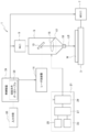
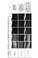
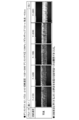
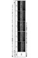
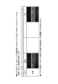
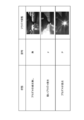
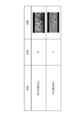
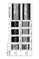
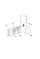
- FIG. 1 is a configuration explanatory diagram conceptually and schematically showing a configuration of a laser cutting apparatus according to an embodiment of the present invention. It is the EPMA analysis result of the cut surface in oxygen cut, clean cut, and easy cut. It is an enlarged photograph which shows the cut surface in clean cut, oxygen cut, and easy cut. It is an enlarged photograph which shows the coating state of the plating layer containing metal to the cut surface in the case of changing laser cutting process conditions. It is an enlarged photograph which shows the coating state of the plating layer containing metal to the cut surface in the case of changing laser cutting process conditions. It is an enlarged photograph which shows the coating state of the plating layer containing metal to the cut surface in the case of changing laser cutting process conditions.
- FIG. 1 It is a schematic diagram which defines the plating metal coating state of a cut surface. It is a figure for demonstrating the inflow situation of the plating metal layer at the time of laser cutting. It is a figure for demonstrating the form of the laser cutting which concerns on embodiment of this invention.
- A is a figure which shows the relationship between the laser beam and the nozzle of cutting gas, and a to-be-cut material
- (b) is a figure which shows the pressure distribution of the gas for cutting and auxiliary gas which acts on a to-be-cut material. is there.
- FIG. 1 It is a figure for demonstrating formation of the plating metal layer which concerns on embodiment of this invention, (a) is a figure which shows the condition of the plating metal layer after the start of laser cutting, (b) is the subsequent It is a figure which shows the condition of a plating metal layer. It is a figure for demonstrating the form of the conventional laser cutting, (a) is a figure which shows the relationship between the nozzle of a laser beam and the gas for cutting, and a to-be-cut material, (b) is a figure to a to-be-cut material. It is a figure which shows the pressure distribution of the gas for cutting which acts.
- FIG. It is a figure for demonstrating formation of the conventional plating metal layer, (a) is a figure which shows the condition of the plating metal layer after the start of laser cutting, (b) is the condition of the subsequent plating metal layer FIG. It is a figure showing an example of laser cutting concerning an embodiment of the present invention. It is a figure which shows another laser cutting example which concerns on embodiment of this invention. It is a figure for demonstrating the measuring method regarding a coating layer, (a) is a figure which shows the method of measuring the ratio (plating inflow length ratio) of the average length of a coating layer, and plate
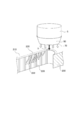
- FIG. 1 is a configuration explanatory diagram conceptually and schematically showing the configuration of a laser cutting apparatus according to an embodiment of the present invention.
- a laser cutting apparatus 1 includes a work table 3 that supports a plate-like workpiece W, and irradiates the workpiece W with a laser beam LB.
- a laser processing head 5 for performing laser cutting processing is provided.
- the work table 3 is provided so as to be relatively movable in the X and Y axis directions relative to the laser processing head 5, and is used to move and position the work table 3 relatively in the X and Y axis directions.
- a positioning motor 7 such as a servo motor is provided.
- a Z-axis motor 9 is provided for moving and positioning the laser processing head 5 in a direction (Z-axis direction) that is relatively close to and away from the workpiece W.
- the laser cutting apparatus 1 is provided with a laser oscillator 11 that oscillates laser light in the far-infrared wavelength region (laser light having a wavelength of 3 ⁇ m or more) such as a CO 2 laser oscillator.
- the laser processing head 5 includes an optical device such as a reflecting mirror 13 that reflects the laser beam LB oscillated from the laser oscillator 11 in the workpiece W direction, a condensing lens 15 that collects the laser beam LB, and the like. 17 is provided. Further, the laser processing head 5 is provided with a nozzle 19 for ejecting assist gas to the laser cutting processing position of the workpiece W so as to be attachable and detachable.
- the laser processing head 5 may include a side nozzle, and the assist gas may be ejected from the side nozzle to the laser processing portion.
- the laser cutting apparatus 1 is provided with an assist gas supply device 21.
- the assist gas supply device 21 supplies, for example, a mixed gas of about 97% nitrogen gas and about 3% oxygen gas, and generates a nitrogen gas supply device 23, an oxygen gas supply source (air supply source) 25, and a mixed gas.
- a mixer 27 is provided.
- the assist gas supply device 21 is provided with a pressure adjusting valve 29 for adjusting the pressure of the assist gas supplied to the laser processing head 5. Further, when the oxygen gas supply source 25 of the assist gas supply device 21 is stopped and only the nitrogen gas supply device 23 is operated, the assist gas can be supplied as an assist gas only with nitrogen gas to the processing unit.
- the configuration for supplying the mixed gas of about 97% nitrogen gas and about 3% oxygen gas as the assist gas to the laser processing unit is not limited to the above-described configuration, but may be a separate configuration. That is, as described in, for example, Japanese Patent No. 3291125, nitrogen and oxygen in the supplied compressed air can be separated by a separation device using a hollow fiber membrane.
- the case of laser cutting using a mixed gas of about 97% (96% or more) nitrogen gas and about 3% (4% or less) oxygen gas as an assist gas is hereinafter simply referred to as easy cut.
- the laser cutting apparatus 1 is provided with a control device 31.
- the control device 31 is composed of a computer and has a function of controlling the relative movement and positioning of the laser processing head 5 with respect to the workpiece W, control of laser output in the laser oscillator 11, and the laser processing head 5. It has the function to control the supply pressure of the assist gas with respect to.
- the laser processing head 5 is moved and positioned relative to the workpiece W in the X, Y, and Z axis directions. Further, the laser beam LB oscillated from the laser oscillator 11 is condensed by the condenser lens 15 and irradiated onto the workpiece W. Further, the assist gas supplied from the assist gas supply device 21 to the laser machining head 15 is ejected from the nozzle 19 to the laser machining portion of the workpiece W, whereby the workpiece W is laser cut.
- FIG. 1 of patent document 1 shows, the laser beam is irradiated to the surface of a plated steel plate, and a plating layer is removed previously. Then, laser cutting processing of the same locus is performed.
- the processing quality can be improved, but the laser processing of the plating layer removing process and the cutting process is required twice. Moreover, since the cut surface of the plated steel plate remains in a state where laser cutting is performed, there is a problem that rust prevention treatment of the cut surface is necessary.
- the embodiment of the present invention cuts the molten and / or evaporated plating layer-containing metal by performing melting and / or evaporation of the plating layer on the upper surface of the plated steel plate when performing laser cutting of the plated steel plate. It has been found that the cut surface can be covered with the flowing plating layer-containing metal.
- a hot-dip plated steel sheet (hereinafter simply referred to as a plated steel sheet) in which a plated layer of 6% aluminum, 3% magnesium, and 91% remaining zinc is coated on the surface of the steel sheet is used. did.
- oxygen cut generally performed in laser cutting processing uses oxygen gas as an assist gas.
- EPMA Electro Probe Micro Analyzer
- the cut surface was covered with an oxide film.
- a laser cutting method using nitrogen gas as an assist gas (hereinafter simply referred to as a clean cut) is performed, depending on the cutting conditions, as shown in the enlarged photograph of FIG.
- Laser cutting of the cut surface CF of the base material B is performed satisfactorily.
- the plating layer M on the upper surface in the vicinity of the upper end portion of the cut surface CF is removed and is extremely thin.
- the covering layer (plating layer) of the cut surface CF is also extremely thin. Therefore, in the clean cut, depending on the appropriate cutting conditions, the cut surface CF can be covered with the molten plating layer-containing metal on the upper surface, and rust (red rust) may not occur.
- the metal contained in the plating layer M is wrapped around the cut surface of the plated steel plate (work) W, and the cut surface CF It was found that a coating of
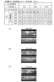
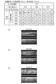
- various cutting conditions such as the cutting speed in laser cutting, the focal position of the condensing lens, the gas pressure of the assist gas, and the pulse frequency of the laser beam were changed to test the coating state of the plating layer on the cut surface. did.
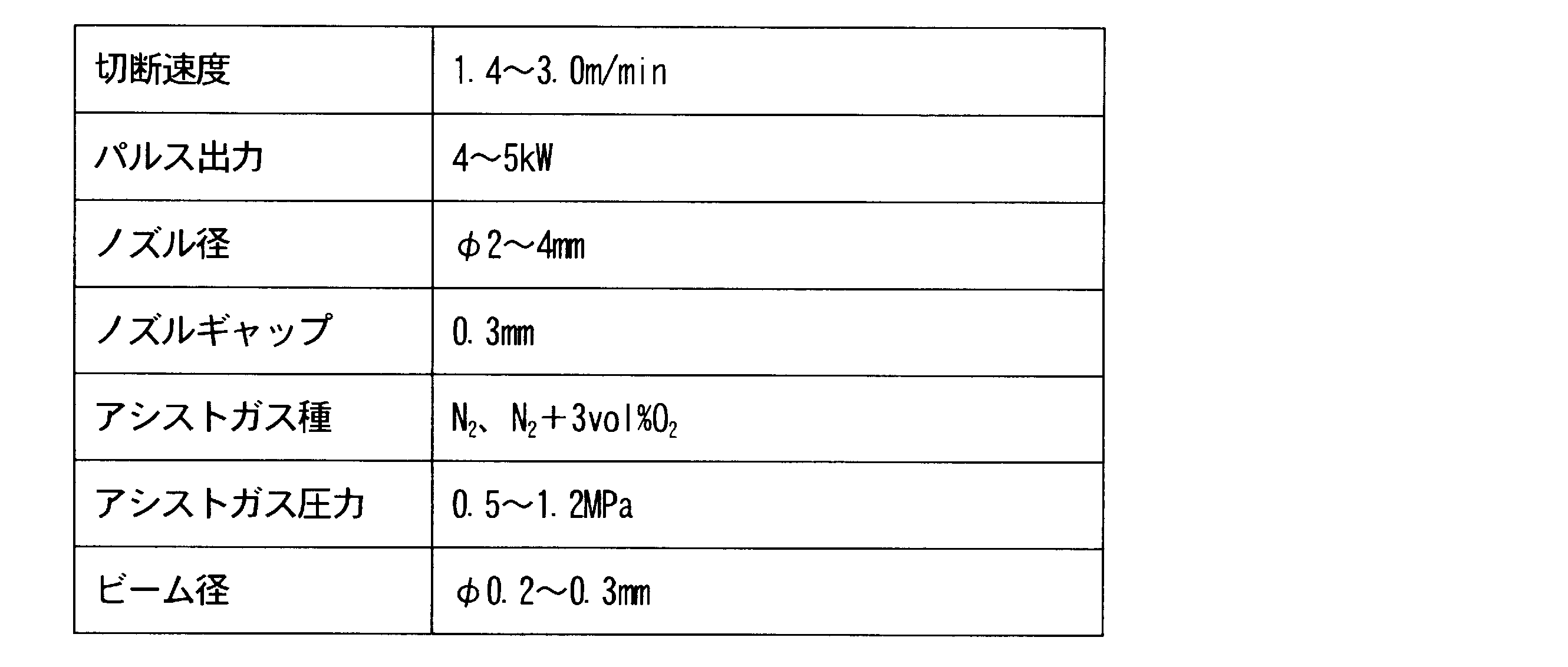
- the test conditions are as follows.
- Cutting sample shape 130mm x 30mm Standard processing conditions ⁇ Nozzle diameter: D4.0 (4.0 mm) ⁇ Cutting speed: F1600 (1600mm / min) Assist gas type: EZ (represents assist gas used in the above-described easy cut.
- the assist gas is a mixed gas of approximately 97% nitrogen and 3% oxygen)
- Assist gas pressure 0.9MPa
- Nozzle gap 0.3 mm (interval between the nozzle and the upper surface of the plated steel sheet)
- Focus position -4.5mm (The work upper surface is 0, the upper side is +, the lower side is-)
- the coating amount of the plating layer-containing metal on the laser cut surface of the plated steel sheet increases as the cutting speed increases (for example, 3840 mm / min). Moreover, the coating amount of the plating layer-containing metal is increased as the focal position is on the + side (for example, +0.5 mm). However, if the focal position is increased to the + side, the energy density on the upper surface of the plated steel sheet is lowered, so it is desirable to set it to one side in laser cutting. Furthermore, as the assist gas pressure is lower (for example, 0.5 MPa), the coating amount of the plating layer-containing metal is increased. When the laser beam was adjusted to a pulse laser or a continuous laser, no significant change was observed in the coating amount of plating.
- the coating amount of the plating layer-containing metal on the laser cut surface varies depending on the processing conditions when performing the laser cutting processing of the plated steel sheet.
- the plating layer-containing metal can be properly coated on the laser cutting surface.
- a laser cutting process was performed on the plated steel sheet under various cutting conditions, and an exposure test was performed in order to check the occurrence of red rust on the laser cut surface.
- an exposure test the cut surface of a laser-cut product obtained by laser-cutting a plated steel sheet was held on the upper surface and left in the field for one month.
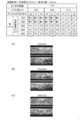
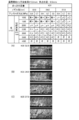
- plasma may or may not be generated on the upper surface of the laser cutting position as shown in FIG. Even when plasma is generated, the generation of weak plasma and the generation of strong plasma (non-weak plasma) can be visually distinguished. Therefore, “no” is generated when no plasma is generated, “p” is generated when weak plasma is generated, and “P” is generated when strong plasma is generated. If the cutting conditions were inappropriate and laser cutting was not possible, “No” was set.
- the laser-cut processed product may be usable depending on the use environment even when the evaluation is “x”.
- K14, K27, and K35 are plating adhesion amount display symbols, and the plating adhesion amounts are as follows. That is, K14 (one-side plating adhesion 70 g / m 2 ), K27 (one-side plating adhesion 145 g / m 2 ), K35 (one-side plating adhesion 175 g / m 2 ).
- S represents a single nozzle
- D represents a double nozzle (double nozzle).
- Double nozzles are already known as disclosed in, for example, Japanese Patent Application Laid-Open No. 11-90672.
- the nozzle gap corresponding to each nozzle diameter is set to 0.3 mm at S2.0, 0.5 mm at D4.0, and 1.0 mm at D7.0. That is, as the nozzle diameter increases, spatter generated at the laser processing position easily enters the nozzle, so the nozzle gap is set to be larger as the nozzle diameter increases.
- the focal position is ⁇ 0.5 mm (the focal position is shown in each figure)
- the plating amount is K14
- the nozzle diameter is S2.0.
- all the evaluations in the exposure test were “x”, and red rust was generated on the entire surface.
- the nozzle having a nozzle diameter of S2.0 did not generate plasma regardless of the assist gas pressure. .
- the evaluation in the exposure test was “x”, and the rust prevention effect on the cut surface was not very desirable.
- the evaluation of the exposure test may be “ ⁇ ” in spite of the absence of plasma in the plating adhesion amount K27 and the nozzle diameter D4.0. Further, at the nozzle diameter D7.0 and the assist gas pressure of 0.9 MPa in FIG. 10, the evaluation is “x” although there is slight plasma generation.
- the cutting speed is preferably in the range of 4000 mm / min to 5000 mm / min.
- the assist gas pressure is 0.5 MPa
- a range of 3000 mm / min to 5000 mm / min is desirable.
- the cutting speed is preferably in the range of 3000 mm / min to 5000 mm / min regardless of the assist gas pressure being 0.9 MPa, 0.7 MPa, or 0.5 MPa. is there.
- the plasma when performing plasma cutting of a metal plate, when plasma is generated, the plasma has a characteristic of absorbing laser light, and irradiation with laser light promotes generation of continuous plasma. And it is known that plasma worsens the cut surface roughness.
- the processing conditions are set so as to promote the generated plasma.
- assist gas is set to low pressure.
- the nozzle gap between the nozzle and the workpiece is slightly larger than usual in order to form a space in which plasma grows.
- the focus position is moved in the (+) direction above the workpiece surface and in the ( ⁇ ) direction below the workpiece surface, the amount moved in the (+) direction compared to the normal focus position.
- the cutting speed is increased.
- the above conditions (i) to (iv) are conditions that facilitate the generation of plasma when performing laser cutting of a metal plate.
- the nozzle diameter is D4.4 compared to S2.0 in the cutting speed range of 1000 mm / min to 2000 mm / min. 0, and D7.0 generates more plasma than D4.0.
- the generation of plasma becomes stronger as the cutting speed is gradually increased from 1000 mm / min to 5000 mm / min.
- the result of the exposure test is more “ ⁇ ”.
- the same tendency is seen also in FIG. 11, FIG.
- the molten and / or evaporated plating layer-containing metal on the upper surface flows to the cut surface, and plasma is generated in order to cover the cut surface by this partial plating. It ’s good.
- “un” indicates that cutting was impossible. That is, when the cutting conditions are inappropriate.
- the lower the assist gas pressure and the higher the cutting speed the more likely the plasma is generated.
- the lower the assist gas pressure In other words, the larger the nozzle diameter and the faster the cutting speed, the stronger the plasma generation. And as the generation of plasma is stronger, the result of the exposure test tends to be “ ⁇ ”.
- “do” indicates that the amount of dross attached is large.
- the results of the exposure tests shown in FIGS. 10 to 17 are stored in the cutting condition data table 33 provided in the control device 31 in the laser cutting processing apparatus 1. That is, in the cutting condition data table 33, the nozzle diameter applied for each plate thickness of the plated steel sheet, the plating adhesion amount for each plate thickness, the nozzle gap for each nozzle diameter, the focal position applied for each plate thickness, and Processing condition data for cutting speed is stored. Further, the cutting condition data table 33 stores the plasma generation data and the evaluation result of the exposure test at the time of laser cutting of the plated steel sheet.
- the control device 31 also includes a cutting condition data table storing processing condition data at the time of easy cutting.
- the evaluation is “ ⁇ ”.
- the evaluation may change depending on the environment such as near the sea or weather conditions.
- the melting range of plating is the thickness of the workpiece, the amount of plating Depending on the laser cutting conditions, a range of 0.27 mm to 0.5 mm from the cut end surface of the workpiece is desirable.
- the laser cutting speed is slow and the amount of heat input is often large. In this case, it is considered that the amount of plating that is melted and / or evaporated increases, and the flow rate into the laser cutting groove increases.
- the laser cutting speed is slow, the irradiation time of the laser beam is long, the heating time is long, the time during which the molten and / or evaporated metal containing the plating layer is kept at a high temperature is prolonged, and the assist is performed.
- the melting and / or evaporation range of the plating layer is a small range of 0.27 mm
- the laser cutting speed is often high and the amount of heat input is often small. In this case, it is considered that the amount melted and / or evaporated is reduced, and the flow rate to the laser cut surface is reduced.
- the melting and / or evaporation range of the plating layer is desirably in the range of 0.27 mm to 0.5 mm from the cut surface.
- the irradiation time of the laser light and the time during which the assist gas acts are appropriate times, and the amount of the molten and / or evaporated plating blown off by the assist gas is reduced. Therefore, it is considered that the cut surface is covered and easily solidified, and the coating amount of the plating layer-containing metal is increased (for example, see D4.0 and D7.0 in FIG. 12).
- both clean cut and easy cut can effectively cover the cut surface with the metal containing the plating layer and prevent the occurrence of red rust when laser cutting is performed while generating plasma. It is.
- the cut surface under the standard condition has an iron component of about 90% (Fe wt%: 89.16), and the plating component has any value of (Zn, Al, Mg). (Weight%: 1.45 or less) is hardly detected. Therefore, red rust is easily generated.
- the iron component of the cut surface is greatly reduced to about 30% (Fe weight%: 32.48). It can be seen that the weight percentage is greatly increased to 43.57, and Al and Mg are increased several times or more, and the plating component covers the entire cut surface. Therefore, it is understood that the generation of red rust is suppressed by the plating component that flows from the upper surface during the laser cutting process and covers the cut surface.
- the upper surface is melted and / or removed during laser cutting.
- the evaporated plating layer-containing metal flows to the cut surface and easily covers the cut surface. Therefore, the thickness of the plating layer in the vicinity of the upper edge of the cut surface in the plated steel sheet was not affected by the heat away from the position separated from the cut surface, that is, melted and / or evaporated during laser cutting. It is thinner than the thickness of the plating layer at the position.
- the plated steel plate is not limited to the above-described plated steel plate, but can be applied to other plated steel plates.
- This embodiment is a surface-treated steel sheet that is cut by a thermal cutting method using gas-cutting, light energy, or electrical energy, using a surface-treated steel sheet coated with a plated metal on the surface of the steel sheet,
- the present invention relates to a surface-treated steel sheet used for home appliances, power distribution facilities, communication facilities, and the like.
- thermal cutting methods include gas cutting, laser cutting using laser light that is light energy, and plasma cutting using plasma that is electric energy.
- the cut surface along the plate thickness direction is in a state where the steel substrate is exposed except for the plating layers on the front and back surfaces. For this reason, the cut surface is in a state of low rust prevention, and depending on the environment in which it is placed, red rust will occur early. Parts that have red rust not only have a poor appearance, but also have a problem in that the volume decreases due to corrosion and the strength as a part is not satisfied. Further, such a problem is more serious as the plate thickness is thicker from the viewpoint of the conspicuousness of rust and the influence on the strength.
- a repair paint having the same components as the plated metal is applied to the cut surface after thermal cutting. However, the cost of the paint and the painting process increases, and there is a problem that the cost of parts increases.
- This method is a method of improving cutting efficiency by using a mixed gas of nitrogen and oxygen containing 2 to 20% oxygen as an assist gas. Judging from the examples, the condition is that the galvanized steel sheet having a thickness of 3 mm is targeted, and the assist gas pressure is 12 bar (1.2 MPa) and the cutting is performed at a speed of 1.8 m / min. However, as shown in the examples described later, since the plating component is not sufficiently present on the cut surface of the surface-treated steel sheet cut by the conventional method, the antirust property is low.
- This second embodiment has been devised to solve the above-described problems, and uses a surface-treated steel sheet coated with a plated metal as a raw material, and uses light energy or electric energy.
- An object of the present invention is to ensure the corrosion resistance of the cut surface by forming the metal contained in the plating layer on the cut surface when cut by the thermal cutting method.
- the heat-cutting part made of the surface-treated steel sheet of the second embodiment has a rust-proof property by wrapping the plated layer-containing metal melted by the heat-cutting to the cut surface without performing repair coating on the cut surface after cutting. Secure.
- a plated steel plate coated with Zn or Zn alloy is used as the surface-treated steel plate.
- the metal contained in the surface plating layer melts and wraps around the cut surface, and the molten metal solidifies and becomes a metal contained in the plating layer.
- the cut surface is covered to obtain a heat-cut product having excellent corrosion resistance of the cut surface.
- a hot dip Zn-based plated steel sheet having a plating composition of mass% and Al: 0.1 to 22.0% may be used.
- what used alloyed Zn plating as a raw material may be used.
- the cut product can have rust resistance exceeding at least one month, and no repair coating is required on the cut surface after cutting. Does not occur.
- the plating layer-containing component of the surface-treated steel sheet which is the material to be cut, is present on the heat-cut surface, that is, some of the metal contained in the plating layer on the steel plate surface has a cut surface. It is characterized by being coated.
- the type of the surface-treated steel sheet is not particularly limited, but it is preferable to use a plated steel sheet coated with Zn or a Zn alloy in consideration of corrosion resistance and damage to the coating component during thermal cutting.
- the original plate of the surface-treated steel plate is not particularly limited, and may be either a hot-rolled steel plate or a cold-rolled steel plate, and the steel type may be any of a very low carbon steel plate, a low carbon steel plate, or the like.
- the plate thickness and the plating adhesion amount there is no need to particularly limit the plate thickness and the plating adhesion amount, and it can be determined in consideration of the corrosion resistance and strength of the heat-cutting parts. For example, when importance is attached to the corrosion resistance, the plating adhesion amount is increased and the heat is applied. It is preferable that the plating layer-containing metal wraps around the cut surface during cutting.
- thermal cutting component As a thermal cutting method for manufacturing the thermal cutting component, light energy or electric energy is used in consideration of the appearance of the cut surface.
- the light energy cutting method include CO 2 laser cutting, YAG laser cutting, and fiber laser cutting.
- the electric energy cutting method include plasma cutting and arc cutting.
- the thermal cutting component of the second embodiment melts the plating layer-containing metal on the surface of the steel plate near the cutting portion at the time of cutting using the above-described cutting method, and wraps around the cutting layer-containing metal melted by the assist gas. It is The ease with which the molten plating layer-containing metal wraps around the cut surface varies depending on the cutting conditions. For example, the amount of heat input during cutting and the pressure of the assist gas are affected.
- the molten plating layer-containing metal may evaporate before it enters the cutting surface. If the heat input is too low, the plating layer-containing metal will not melt sufficiently, or the steel sheet itself will be cut. It may be possible not to do so. On the other hand, if the pressure of the assist gas is too high, the plating layer-containing metal that wraps around the cut surface is blown off excessively.
- the rust prevention property of the cut surface varies depending on the conditions of the surface-treated steel sheet used as the material.
- the greater the amount of plating attached the greater the proportion of the plating layer-containing metal that melts against a constant heat input during thermal cutting.
- the thinner the plate thickness the smaller the area of the cut surface to be covered by the plating layer-containing metal.
- the present inventors have grasped that there is a condition that the metal contained in the plating layer tends to wrap around the cut surface at the time of thermal cutting by the combination of such cutting conditions and material conditions. Improved cutting parts were completed.
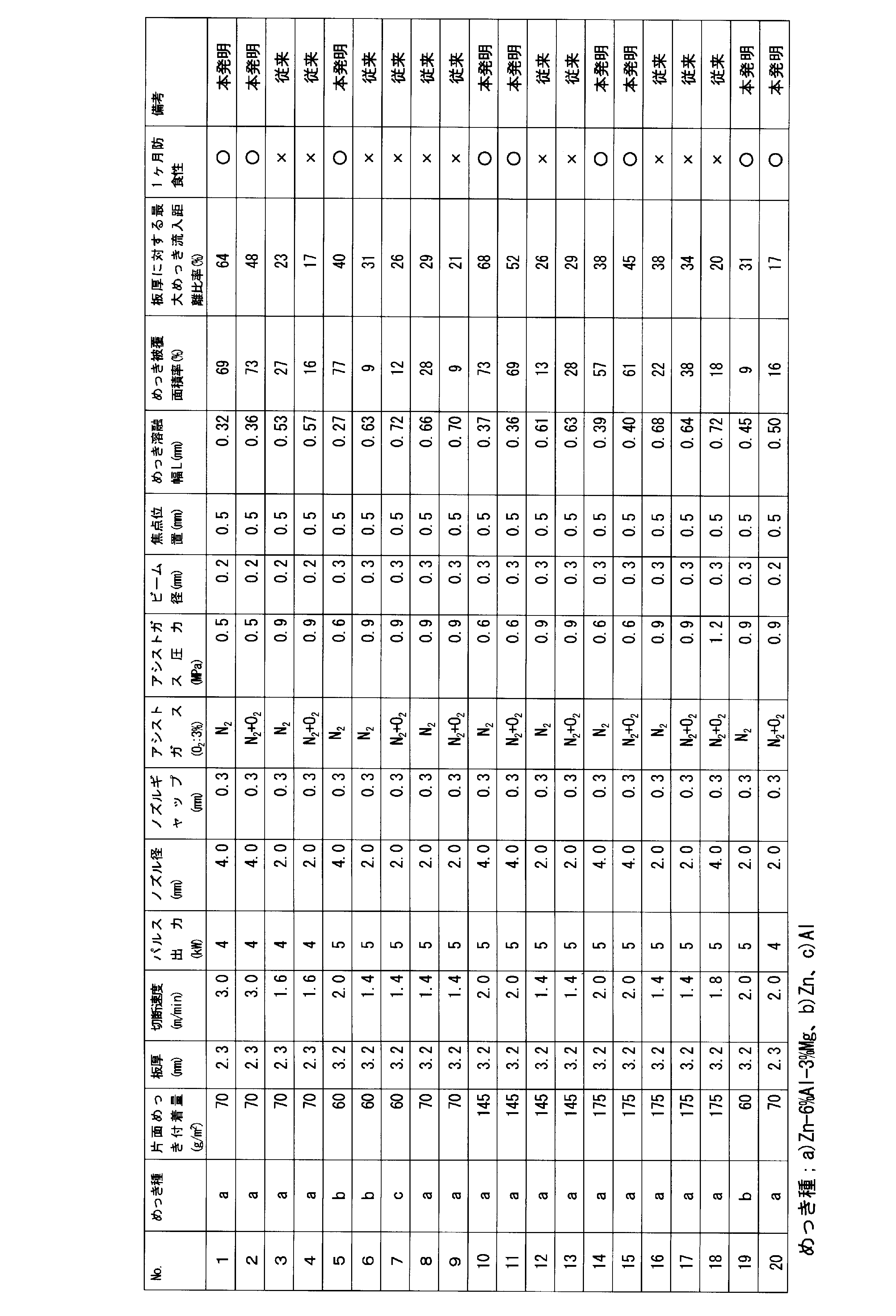
- the materials used were Zn-6% Al-3% Mg plated steel sheet, Zn plated steel sheet, and Al plated steel sheet shown in Table 1, and the equipment used the most general-purpose CO 2 laser. Cutting with a combination of conditions.
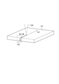
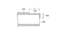
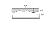
- the plating melt width L which is the width of the region where the plating layer thickness on the upper surface side shown in FIG. Further, the coating state of the plating layer-containing metal on the cut surface shown in FIG.
- the results are shown in Table 3.
- the plating melt width L is 0.27 mm to 0.5 mm, and the coating area ratio of the molten plating layer-containing metal is 10% or more, or the maximum inflow distance of the molten plating layer-containing metal is 30% or more of the plate thickness In such a case, the cut product of any condition had a rust prevention property exceeding one month.
- the surface-treated steel sheet is coated with the plating metal on the surface of the steel sheet, and the cut surface contains the plating layer on the surface of the steel sheet. It becomes a surface-treated steel sheet covered with metal. And the area where the metal contained in the plating layer on the steel plate surface covers the cut surface is 10% or more of the cut surface area, or the metal contained in the plating layer on the steel plate surface is the surface or the back surface of the surface-treated steel plate. Therefore, it is desirable that the cut surface is covered with 30% or more of the plate thickness. Further, it is desirable that the width of the thin portion of the plating layer is 0.27 mm to 0.5 mm along the vertical direction from the cut surface.
- reference numeral 101 denotes a material
- 102 denotes a laser beam
- 103 denotes a cut surface
- 104 denotes a plated metal
- 105 denotes a cut surface
- 106 denotes a plating layer-containing metal maximum inflow distance
- 107 denotes a laser beam.
- 3rd Embodiment is related with the member excellent in end surface corrosion resistance, and is related with the member cut
- thermal cutting methods include gas cutting by gas combustion, laser cutting by laser light, and plasma cutting by thermal plasma. Laser cutting is frequently used because damage to the plated metal of the surface-treated steel sheet is small and the appearance of the cut surface is good.
- the cut surface along the thickness direction is usually in a state where the steel substrate is exposed. Since such a cut surface has low corrosion resistance, red rust occurs at an early stage depending on the use environment, resulting in poor appearance. Furthermore, a product in which red rust is generated has a problem that the required mechanical strength is insufficient because the volume decreases due to corrosion.
- Thick plate products are prone to red rust on the appearance and require practical mechanical strength, so the above problems become apparent.
- a repair coating having the same function as that of the plated metal is applied to the cut surface to ensure the corrosion resistance of the entire product.
- this measure has led to an increase in product cost because the painting work is performed using paint.
- the third embodiment has been devised to solve such problems, and is a member made of a surface-treated steel sheet coated with a plated metal, and cut after laser cutting. It aims at providing the member with which the corrosion resistance in the surface was ensured. Moreover, it aims at provision of the laser cutting method which manufactures said member.
- the present inventors have found a phenomenon in which the plated metal layer on the surface of the steel sheet is melted by laser irradiation heat and flows into the cut surface side when laser-cutting the plated steel sheet.
- the present embodiment has been completed. Specifically, the following are provided.
- the third embodiment is a laser cutting method for a surface-treated steel sheet coated with a plated metal layer on the surface of the steel sheet, and laser is cut using a cutting gas containing oxygen gas, nitrogen gas, or a mixed gas thereof.
- a cutting gas containing oxygen gas, nitrogen gas, or a mixed gas thereof is sprayed onto the molten plated metal layer to flow the molten plated metal layer into the cut surface.
- the third embodiment is the laser cutting method according to (1), in which a plurality of nozzles for injecting the auxiliary gas are arranged around the nozzles for the cutting gas to perform laser cutting. .
- the third embodiment performs laser cutting by arranging a ring-shaped nozzle for injecting the auxiliary gas around the cutting gas nozzle. is there.
- the corrosion resistance of the entire cut surface can be secured by the sacrificial anode effect. Since the conventional repair coating is not required on the cut surface after laser cutting, the product cost can be reduced.
- the laser cutting process is performed by moving the laser beam LB while irradiating the laser beam LB from the laser processing head 5 onto the surface of the surface-treated steel plate 200 to melt the surface-treated steel plate 200. , Processed into a predetermined shape.
- the plated metal layer 210 coated on the surface of the surface-treated steel plate 200 evaporates on the cut surface 220 (cut portion) by heating the irradiated laser beam LB.
- the heat of the laser beam irradiation is also conducted and heated in the plated metal layer located around the cut portion.
- the plated metal layer 230 in that region is in a molten state, and a part thereof is evaporated. Since fluidity is generated in the plated metal layer 230 in the molten state, the molten plated metal flows into the cut surface in a form that wraps around the cut surface side, spreads and moves on the cut surface, and is then cooled and solidified. Then, a coating layer 250 containing a plating metal is formed. By forming the coating layer 250 containing the plated metal, the corrosion resistance equivalent to that of the surface-treated steel sheet is maintained even on the cut surface, and a member having excellent end face corrosion resistance is obtained. For this reason, good corrosion resistance can be ensured without repairing the cut surface after laser cutting. As shown in FIG. 23, the coating layer 250 includes a portion distributed in a form connected to the plated metal layer 210.
- a laser beam is usually irradiated from the tip of the irradiation nozzle toward the material to be cut, and a cutting gas (assist gas) is blown from the periphery of the laser light to the material to be cut.
- This cutting gas is used for the purpose of removing the evaporated or molten material from the cut portion.
- the present inventors have found that the flow of the auxiliary gas promotes the flow of the molten plated metal into the cut surface by spraying the auxiliary gas to the peripheral region of the cutting portion and performing laser cutting.
- the auxiliary gas nozzle is arranged around the cutting gas nozzle, and laser cutting is performed while the auxiliary gas is injected into the peripheral area of the cutting portion.
- the surface-treated steel sheet is not particularly limited.
- a plated steel sheet coated with a Zn-based, Zn-Al-based, Zn-Al-Mg-based, Zn-Al-Mg-Si-based metal plating or alloy plating can be used.
- a steel sheet on which a Zn—Al—Mg alloy plating is applied is preferable.
- the base material of the surface-treated steel sheet may be either a hot rolled steel sheet or a cold rolled steel sheet, and an extremely low carbon steel sheet, a low carbon steel sheet, or the like can be used.
- the plate thickness of the surface-treated steel sheet, the Zn content of the plating layer, and the amount of plating deposited per side are not particularly limited. An appropriate range can be selected in consideration of corrosion resistance and mechanical strength.
- the Zn content of the plating layer is preferably 40% or more, more preferably 80% or more.
- the Mg content of the Zn—Al—Mg alloy plating is large, the viscosity and surface tension when the plated metal layer is in a molten state is lowered and the fluidity is increased, so that the inflow to the cut surface is promoted. This is preferable.
- the plating adhesion amount per side is preferably 20 g / m 2 or more, more preferably 30 g / m 2 or more and 90 g / m 2 or more on the surface on the side irradiated with laser light.
- the ratio of the plating adhesion amount / plate thickness based on the plating adhesion amount (g / m 2 ) per one surface and the plate thickness (mm) is preferably 1.3 ⁇ 10 or more, and 2.5 ⁇ 10 or more. Is more preferable.
- the plated metal layer present on the cut surface may cover all or part of the cut surface.
- the plated metal is preferentially dissolved over the base steel due to the sacrificial anode effect, and the corrosion resistance of the surface-treated steel sheet is maintained even at the cut surface.
- the average length of the coating layer is preferably 25% or more of the thickness of the steel plate.
- the length of the coating layer is referred to as “plating inflow length”
- the ratio of the average length of the coating layer to the thickness of the steel sheet is referred to as “plating inflow length ratio”.
- the ratio that the coating layer occupies the cut surface is referred to as “coverage”.
- the coverage is preferably 10% or more. If the coverage is less than 10%, sufficient corrosion resistance cannot be ensured by the inflowing plated metal.
- Cutting gas is sprayed from the periphery of the laser beam onto the surface-treated steel sheet.
- the cutting gas is mainly used for the purpose of removing the burned and evaporated or melted material from the cutting part.
- As the cutting gas O 2 gas, air, N 2 gas, or a mixed gas thereof can be used.
- the oxide layer, the nitride layer, or the mixed layer thereof is formed on the surface of the cut surface that is exposed when the steel plate is cut by laser light irradiation. Thereafter, the plated metal layer of the surface-treated steel sheet flows into the cut surface to form the coating layer.
- the coating layer is composed of the oxide layer, the nitride layer, or a mixed layer thereof (hereinafter referred to as “oxide layer”). Etc. ”))).
- the auxiliary gas if the same type of gas as the cutting gas is used as the auxiliary gas, it contributes to the formation of the oxide layer and the like.
- the molten plated metal flowing into the cut surface side tends to spread and move on the surface of the cut surface. From this, it is thought that said oxide layer etc. have the effect
- the third embodiment is a laser cutting method for a surface-treated steel sheet coated with a plated metal layer on the steel sheet surface, and performs laser cutting using a cutting gas containing oxygen gas, nitrogen gas, or a mixed gas thereof.
- a cutting gas containing oxygen gas, nitrogen gas, or a mixed gas thereof is used as a cutting gas containing oxygen gas, nitrogen gas, or a mixed gas thereof.
- an auxiliary gas is sprayed onto the molten plated layer to flow the plated metal layer into the cut surface.
- a nozzle for injecting auxiliary gas can be arranged around the nozzle for cutting gas to supply auxiliary gas.
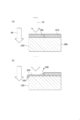
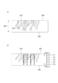
- FIG. 24 is the form example, Comprising: When the laser cutting nozzle is viewed in cross section, the material to be cut (surface-treated steel plate 200), the irradiated laser beam, the cutting gas to be injected, and the auxiliary It is the figure which showed the relationship with gas typically.
- a nozzle (cutting gas supply means 30) for injecting cutting gas is arranged around the laser light irradiation nozzle 19, and a nozzle (auxiliary gas supply means 40) for injecting auxiliary gas is arranged around the nozzle.
- the range in which the cutting gas injected from the cutting gas supply nozzle 30 acts is a region including the cutting surface 220, whereas the auxiliary gas 70 injected from the auxiliary gas supply nozzle 40 has a cutting portion (cutting surface). 220).
- FIG. 24B is a schematic diagram showing the pressure distribution at which the cutting gas 60 and the auxiliary gas 70 act on the material to be cut 200. As shown in FIG. 24 (b), a constant pressure is applied also in the peripheral region of the cut surface 220.
- 25 (a) and 25 (b) are schematic diagrams showing the formation of a coating layer containing a plated metal.
- FIG. 25 (a) when the auxiliary gas 70 is blown against the molten plated metal layer 230 on the surface of the steel plate 200 during laser cutting, the molten metal is melted as shown in FIG. 25 (b).
- the plated metal layer 230 moves toward the cut surface and flows into the cut surface 220 to form the coating layer 250.
- FIG. 26 (a), (b), and (a), (b) of FIG. 27 are diagrams schematically showing a nozzle cutting state according to a conventional example using only a cutting gas.
- the cutting gas 60 is jetted toward the cutting part (cutting surface 220), and a part of the gas 60 diffuses into the peripheral region of the cutting part (FIG. 26A).
- the pressure of the cutting gas 60 acting on the molten plated metal layer is low (FIG. 26B). Therefore, as shown in FIGS. 27A and 27B, the evaporated plating metal 260 is removed from the molten plated metal layer 230, and the molten plated metal layer 230 flows into the cut surface. It is thought that it cannot be made.
- the type of laser light to be irradiated is not particularly limited.
- Conditions such as the spot diameter, output, and moving speed of the laser beam at the time of cutting can be set as appropriate depending on the thickness and processed shape of the surface-treated steel sheet to be cut.
- the plated metal layer of the surface-treated steel sheet is heated by laser cutting to reach a molten state.
- the thickness (t: unit mm) of the surface-treated steel sheet As parameters affecting the temperature rise of the plated metal layer, the thickness (t: unit mm) of the surface-treated steel sheet, laser output (P: unit kW), cutting speed (v: unit m / min), laser cutting width (w : Unit mm). Even if the laser output is the same, the degree of temperature rise varies depending on the plate thickness and cutting speed. Therefore, an index of “P / v ⁇ t ⁇ w” was used so that various heating conditions for the plated metal layer could be compared.
- the index is a numerical value obtained by dividing the laser output P (kW) by the cutting speed v (m / min), the plate thickness t (mm), and the laser cutting width w (mm). In this specification, this index is referred to as “laser heat input index”.
- the laser heat input index is preferably in the range of 0.79 to 2.57 in order to allow the plated metal to flow into the cut end face to form a good coating layer. If it is less than 0.79, the amount of heat input at the time of cutting is too small, so that dross adheres to the cutting part and cutting cannot be performed. On the other hand, if it exceeds 2.57, the amount of heat input is excessive, so that the amount of plated metal flowing into the cut end face decreases due to evaporation of the plated metal, and the end face corrosion resistance decreases.
- the cutting gas it is preferable to perform laser cutting using oxygen gas, nitrogen gas, or a mixed gas thereof to form a cut surface having an oxide layer, a nitride layer, or a mixed layer thereof.
- oxygen gas nitrogen gas, or a mixed gas thereof
- a mixed gas thereof can be used as the cutting gas.
- An inert gas for example, Ar
- the flow rate and pressure of the cutting gas can be appropriately set depending on the thickness of the surface-treated steel sheet and the cutting conditions.
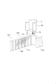
- the auxiliary gas supply means may be any means that blows the auxiliary gas 70 after laser cutting.
- a nozzle 80 for injecting auxiliary gas 70 is arranged around the processing head 5 for injecting cutting gas.
- a plurality of auxiliary gas side nozzles 80 may be disposed on the side of the machining head 5.
- the machining head 5 includes an auxiliary gas nozzle 90 as an outer nozzle that surrounds an inner nozzle (not shown) that blows away the molten metal in the cutting groove.
- the auxiliary gas nozzle 90 has a function of injecting the auxiliary gas 70 onto the molten plated metal layer 230 to guide the molten plated metal layer to the cut surface 220.
- a laser processing head used in the laser cutting processing method includes a nozzle that ejects an assist gas to a laser processing portion of a plated steel plate, and a cut surface formed by blowing molten metal with the assist gas ejected from the nozzle. Further, it is desirable that the auxiliary gas nozzle for ejecting the auxiliary gas for guiding the plating layer-containing metal in a molten state on the upper surface of the plated steel sheet is provided. That is, the molten metal having a range of 0.27 mm to 0.5 mm from the cut surface is guided to the cut surface by the auxiliary gas.
- the auxiliary gas nozzle assists the cut groove after the laser cutting process in a range larger than the width of the cut groove formed by the laser cutting process, that is, a range including the molten plated metal layer 230. It is desirable that the gas be ejected.
- the type of auxiliary gas is not particularly limited. What is necessary is just to promote the inflow of the molten plating metal.
- the gas composition may be the same as that of the cutting gas, and oxygen gas, nitrogen gas, or a mixed gas thereof can be used. Further, the gas composition may be different from the cutting gas, or only an inert gas (for example, Ar) may be used.
- the flow rate of the auxiliary gas can be selected according to the thickness of the surface-treated steel sheet, the moving speed of the laser beam, and the like. As described above, the auxiliary gas has an action of promoting the flow of the molten plated metal layer toward the cut surface.
- the flow rate of the auxiliary gas is preferably 20 L / min or more. When the flow rate of the auxiliary gas is small, the inflow of the plating metal at the cut surface is not sufficient. When the flow rate is large, the inflow of the plating metal tends to increase. If the flow rate is excessively large, the molten plated metal is excessively blown off, which hinders the formation of the coating layer, which is not preferable.
- test material No. Reference numeral 47 is a reference example to which plasma cutting using air is applied.
- the plating layer has a plating composition of Zn—Al—Mg, Zn—Al, Zn, or Al—Si.
- the test material described as “Zn-6Al-3Mg” in the “Plating composition” column of Tables 4 and 5 means a steel sheet having a Zn-based plating layer containing 6 mass% Al and 3 mass% Mg. To do.
- the plating adhesion amount per side (g / m 2 ), the thickness of the steel sheet (mm), and the ratio of the plating adhesion amount to the plate thickness (plating adhesion amount / plate thickness Test materials with different ratios) were used.
- the plating adhesion amount per one side shown in Tables 4 and 5 is a numerical value on the surface on the side irradiated with laser light.
- the laser cutting was performed by combining the following conditions.
- A Laser oscillation method: CO 2 laser
- B Laser cutting width (mm): 0.24 to 0.40
- C Laser output (kW): 2, 4, 6
- D Cutting speed (m / min): 0.6 to 7.0
- E Types of cutting gas: nitrogen (N 2 ), oxygen (O 2 ), nitrogen + 3% oxygen (N 2 + 3% O 2 ), argon (Ar)
- F Gas pressure for cutting (MPa): 0.05 to 1.4
- Nozzle type of auxiliary gas side nozzle (A type: see FIG. 28), ring nozzle (B type: see FIG.
- auxiliary gas nitrogen (N 2 ), oxygen (O 2 ), nitrogen + 3% oxygen (N 2 + 3% O 2 ), argon (Ar)
- Auxiliary gas flow rate (L / min): 15 to 1900 The test material after cutting was photographed to obtain the image data of the cut surface, and the average length of the coating layer (plating inflow length ratio) and the plating coverage were determined. Moreover, the exposure test demonstrated later was done with respect to the test material, and the end surface rusting rate was calculated
- EPMA electron beam microanalyzer
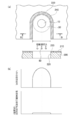
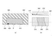
- FIG. 30 (a) schematically shows a method for measuring the average length of the coating layer.
- the coating layer shows a form in which the plating metal flows from the steel plate surface 320 to the cut surface and extends toward the back surface 330 of the steel plate.
- five plating inflow portions 310 surrounded by circular marks are selected as main inflow portions from within the observed region, and the lengths to the tips (plating) are selected.
- the inflow length 340) is measured, and the ratio of the plating inflow length 340 to the plate thickness 350 of the steel sheet (this specification is referred to as “plating inflow length ratio”) is calculated as an average value of five points. Asked. By the average value, it was set as the average length of the coating layer which concerns on this embodiment.
- a wire 420 was arranged on one end side of the test material 390 to give the test material 390 an inclination angle ⁇ .
- the plating layer, the oxide layer, and the like on the cut surface of the test material 390 are obliquely polished, and as shown in FIG. ,
- the steel plate substrate 370, the oxide layer 360, and the plated metal 310 were exposed side by side.
- the width of the oxide layer 360 was measured.
- the thickness of the oxide layer or the like was calculated from the measured width of the oxide layer or the like and the inclination angle ⁇ at the time of embedding.
- the average value was calculated by measuring the thickness of the oxide layer or the like at any three locations in the observation area 410 of the cut surface by the same procedure, and the value was used as the thickness of the oxide layer or the like according to the present embodiment.
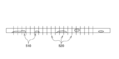
- End surface rusting rate About the corrosion resistance of the member of this invention, the exposure test was done in outdoor air for 60 days using the test material, and it evaluated by the ratio which the red rust generate
- the rusting rate of red rust is referred to as “edge rusting rate”.
- a measurement range having a length of 150 mm was set near the center of the cut test material.
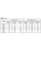
- Tables 4 and 5 show the results of measuring the plating inflow length rate, the plating coverage rate, the thickness of the oxide layer, etc., and the end surface rusting rate.
- the Zn component was distributed so as to flow from the top to the bottom of the plate surface on which the laser light was incident (FIG. 33). According to this distribution form, it is presumed that the Zn component on the cut surface is such that the plated metal layer on the steel sheet surface has come to the cut surface side.
- the test material No. using the N 2 gas cutting gas was obtained. 1, no. In 2 etc., a nitrided layer was formed in a region where no Zn component was present on the cut surface.
- a cutting gas a test material No. using a mixed gas containing 3% O 2 in N 2 gas. 4, no. No. 5, etc., test material No. using O 2 gas. 7, no. 11 and the like, an oxide layer, a nitride layer, or a mixed layer thereof was formed in a region where no Zn component was present on the cut surface.
- the molten plated metal layer on the steel sheet surface flows into the cut surface side and flows into the above-described oxide layer or the like. It is presumed that a coating layer was formed.
- test material No. corresponding to the present invention example. 1-No. No. 29 had a plating inflow length ratio of 25% or more, a coverage ratio occupying a cut surface of 10% or more, and had an oxide layer or the like under the coating layer.
- Test material No. 1-No. The end face rusting rate of 29 was 10% or less, indicating good end face corrosion resistance.
- the Zn content of the plating metal layer is 40% or more
- the plating adhesion amount per side is 20 g / m 2 or more
- the average thickness of the oxide layer or the like is 0.1 ⁇ m or more
- the plating adhesion amount The ratio between (g / m 2 ) and the plate thickness (mm) of the steel sheet was 1.3 ⁇ 10 or more.
- test material No. 1-No. In the laser cutting method 29, a cutting gas containing oxygen gas, nitrogen gas or a mixed gas thereof was used, and an auxiliary gas was also used.
- the type of auxiliary gas is test material No. No. 15 used argon gas, and other test materials used oxygen gas or nitrogen gas or a mixed gas of both.
- As the auxiliary gas nozzle a side nozzle (A) or a ring nozzle (B) was used.
- Their laser heat input index (P / v ⁇ t ⁇ w) was selected in the range of 0.79 to 2.57, and laser cutting was performed.
- test material No. of the comparative example shown in Table 5 was used.
- 30-No. 45 is a surface-treated steel sheet having a plated metal layer containing Zn as in this example of Table 4.
- the plating inflow length ratio was less than 25%
- the end surface rust ratio exceeded 10%
- the corrosion resistance was inferior to that of the examples of the present invention.
- test material No. 30-No. 38 is a specific example in which no auxiliary gas was used in combination.
- Test material No. 39-No. No. 42 is an example in which the auxiliary gas is used together and the laser heat input index (P / v ⁇ t ⁇ w) is outside the range of 0.79 to 2.57.
- Test material No. No. 41 has a laser heat input index of less than 0.79 and could not be cut due to insufficient heating.
- Test material No. No. 43 is an example carried out at a flow rate of auxiliary gas of less than 20 L / min.
- No. 44 is an example in which the ratio of plating adhesion / plate thickness was less than 1.3 ⁇ 10.
- Reference numeral 45 is an example in which an argon gas is used as a cutting gas and an oxidation and nitride layer is not generated.
- Test material No. shown in Table 5 No. 46 is a comparative example using a plating metal (Al—Si) not containing Zn.
- No. 47 is a comparative example using plasma cutting instead of laser cutting, and in all cases, the end surface rusting rate greatly exceeded 10%, and the end surface corrosion resistance was inferior.
- laser cutting can be performed without removing plating on a plated steel sheet. And when performing laser cutting of a plated steel plate, the plated layer-containing metal on the upper surface which has been melted and / or evaporated can flow to the cut surface to cover the cut surface. Therefore, it is possible to efficiently perform the laser cutting process on the plated steel sheet, and it is not necessary to perform the rust prevention treatment on the cut surface again after the laser cutting process.
Abstract
Description
材料:アルミニウム6%、マグネシウム3%、残り亜鉛91%のめっきを表面に被覆しためっき鋼板、板厚t=2.3mm、K35(片側めっき付着量175g/m2)
切断サンプル形状:130mm×30mm
標準加工条件
・ノズル直径:D4.0(4.0mm)
・切断速度:F1600(1600mm/min)
・アシストガス種類:EZ(前述したイージーカットに使用されるアシストガスを表わす。この場合のアシストガスは、窒素約97%、酸素3%の混合ガスである)
・アシストガス圧:0.9MPa
・ノズルギャップ:0.3mm(ノズルとめっき鋼板の上面との間隔)
・焦点位置:-4.5mm(ワーク上面を0として、上側を+、下側を-としている)上記の標準加工条件の各条件を変化して加工を行った結果は次のとおりであった。 Laser cutting machine: Amada Co., Ltd., FOM2-3015RI
Material: Plated steel sheet with 6% aluminum, 3% magnesium, and 91% remaining zinc coated on the surface, plate thickness t = 2.3 mm, K35 (one-side plating adhesion 175 g / m 2 )
Cutting sample shape: 130mm x 30mm
Standard processing conditions ・ Nozzle diameter: D4.0 (4.0 mm)
・ Cutting speed: F1600 (1600mm / min)
Assist gas type: EZ (represents assist gas used in the above-described easy cut. In this case, the assist gas is a mixed gas of approximately 97% nitrogen and 3% oxygen)
・ Assist gas pressure: 0.9MPa
・ Nozzle gap: 0.3 mm (interval between the nozzle and the upper surface of the plated steel sheet)
・ Focus position: -4.5mm (The work upper surface is 0, the upper side is +, the lower side is-) The results of machining with each of the above standard machining conditions changed were as follows. .

表面処理鋼板は、特に限定するものではない。Zn系、Zn-Al系、Zn-Al-Mg系、Zn-Al-Mg―Si系の金属めっき又は合金めっきなどを被覆しためっき鋼板を用いることができる。Zn-Al-Mg系の合金めっきが施された鋼板が好ましい。表面処理鋼板の基材は、熱延鋼板、冷延鋼板のいずれでもよく、極低炭素鋼板や低炭素鋼板などを用いることができる。 (Surface-treated steel sheet)
The surface-treated steel sheet is not particularly limited. A plated steel sheet coated with a Zn-based, Zn-Al-based, Zn-Al-Mg-based, Zn-Al-Mg-Si-based metal plating or alloy plating can be used. A steel sheet on which a Zn—Al—Mg alloy plating is applied is preferable. The base material of the surface-treated steel sheet may be either a hot rolled steel sheet or a cold rolled steel sheet, and an extremely low carbon steel sheet, a low carbon steel sheet, or the like can be used.
切断面に存在するめっき金属層は、切断面の全部または一部を被覆すればよい。切断面にめっき金属層が一部存在すると、犠牲陽極効果により、めっき金属が基材の鋼よりも優先して溶解して、表面処理鋼板の耐食性は、切断面においても保持される。十分な耐食性を確保する観点では、被覆層の平均長さは、鋼板の板厚の25%以上であることが好ましい。本明細書では、被覆層の長さを「めっき流入長さ」といい、鋼板の板厚に対する被覆層の平均長さの割合を「めっき流入長さ率」という。 (Coating layer)
The plated metal layer present on the cut surface may cover all or part of the cut surface. When a part of the plated metal layer is present on the cut surface, the plated metal is preferentially dissolved over the base steel due to the sacrificial anode effect, and the corrosion resistance of the surface-treated steel sheet is maintained even at the cut surface. From the viewpoint of ensuring sufficient corrosion resistance, the average length of the coating layer is preferably 25% or more of the thickness of the steel plate. In this specification, the length of the coating layer is referred to as “plating inflow length”, and the ratio of the average length of the coating layer to the thickness of the steel sheet is referred to as “plating inflow length ratio”.
レーザ切断では、切断用ガスがレーザ光の周囲から表面処理鋼板に吹き付けられる。切断用ガスは、主に、材料切断部の燃焼及び蒸発または溶融した材料を切断部分から排除する目的で用いられる。切断用ガスは、O2ガス、空気、N2ガス等、または、これらの混合ガスを使用することができる。当該酸化層若しくは窒化層又はこれらの混合層は、レーザ光の照射によって鋼板が切断されて露出した切断面の表面に形成される。その後、表面処理鋼板のめっき金属層が当該切断面に流入して、上記の被覆層を形成することから、被覆層は、上記の酸化層若しくは窒化層又はこれらの混合層(以下、「酸化層等」と記載することもある。)の上に形成される形態を有している。また、補助ガスにも切断用ガスと同じ種類のガスを使用すると、上記の酸化層等の生成に寄与する。 (Oxide layer or nitride layer or mixed layer thereof)
In laser cutting, cutting gas is sprayed from the periphery of the laser beam onto the surface-treated steel sheet. The cutting gas is mainly used for the purpose of removing the burned and evaporated or melted material from the cutting part. As the cutting gas, O 2 gas, air, N 2 gas, or a mixed gas thereof can be used. The oxide layer, the nitride layer, or the mixed layer thereof is formed on the surface of the cut surface that is exposed when the steel plate is cut by laser light irradiation. Thereafter, the plated metal layer of the surface-treated steel sheet flows into the cut surface to form the coating layer. Therefore, the coating layer is composed of the oxide layer, the nitride layer, or a mixed layer thereof (hereinafter referred to as “oxide layer”). Etc. ”))). In addition, if the same type of gas as the cutting gas is used as the auxiliary gas, it contributes to the formation of the oxide layer and the like.
第3の実施形態は、鋼板表面にめっき金属層で被覆された表面処理鋼板のレーザ切断方法であって、酸素ガス若しくは窒素ガス又はこれらの混合ガスを含む切断用ガスを用いてレーザ切断を行い、切断面を形成した後、溶融しためっき層に対して補助ガスを噴射して前記めっき金属層を切断面に流入させる、レーザ切断方法である。 (Laser cutting method)
The third embodiment is a laser cutting method for a surface-treated steel sheet coated with a plated metal layer on the steel sheet surface, and performs laser cutting using a cutting gas containing oxygen gas, nitrogen gas, or a mixed gas thereof. In this laser cutting method, after the cut surface is formed, an auxiliary gas is sprayed onto the molten plated layer to flow the plated metal layer into the cut surface.
であるため、めっき金属の蒸発により、切断端面に流入するめっき金属量が低減し、端面耐食性が低下する。 The plated metal layer of the surface-treated steel sheet is heated by laser cutting to reach a molten state. As parameters affecting the temperature rise of the plated metal layer, the thickness (t: unit mm) of the surface-treated steel sheet, laser output (P: unit kW), cutting speed (v: unit m / min), laser cutting width (w : Unit mm). Even if the laser output is the same, the degree of temperature rise varies depending on the plate thickness and cutting speed. Therefore, an index of “P / v × t × w” was used so that various heating conditions for the plated metal layer could be compared. The index is a numerical value obtained by dividing the laser output P (kW) by the cutting speed v (m / min), the plate thickness t (mm), and the laser cutting width w (mm). In this specification, this index is referred to as “laser heat input index”. The laser heat input index is preferably in the range of 0.79 to 2.57 in order to allow the plated metal to flow into the cut end face to form a good coating layer. If it is less than 0.79, the amount of heat input at the time of cutting is too small, so that dross adheres to the cutting part and cutting cannot be performed. On the other hand, if it exceeds 2.57, the amount of heat input is excessive, so that the amount of plated metal flowing into the cut end face decreases due to evaporation of the plated metal, and the end face corrosion resistance decreases.
(b)レーザ切断幅(mm):0.24~0.40
(c)レーザ出力(kW):2,4,6
(d)切断速度(m/min):0.6~7.0
(e)切断用ガスの種類:窒素(N2),酸素(O2),窒素+3%酸素(N2+3%O2),アルゴン(Ar)
(f)切断用ガス圧(MPa):0.05~1.4
(g)補助ガスのノズル型:サイドノズル(A型:図28参照),リングノズル(B型:図29参照)
(h)補助ガスの種類:窒素(N2),酸素(O2),窒素+3%酸素(N2+3%O2),アルゴン(Ar)
(i)補助ガス流量(L/min):15~1900
切断後の試験材は、その切断面を写真撮影して画像データとして取得し、被覆層の平均長さ(めっき流入長さ率)、めっき被覆率を求めた。また、試験材に対して、後に説明する暴露試験を行って、端面発錆率を求めた。さらに、後に説明する方法により、酸化層等の厚みを測定した。また、上記の切断面において、電子線マイクロアナライザ(EPMA)による成分分析を行った。 (A) Laser oscillation method: CO 2 laser (b) Laser cutting width (mm): 0.24 to 0.40
(C) Laser output (kW): 2, 4, 6
(D) Cutting speed (m / min): 0.6 to 7.0
(E) Types of cutting gas: nitrogen (N 2 ), oxygen (O 2 ), nitrogen + 3% oxygen (N 2 + 3% O 2 ), argon (Ar)
(F) Gas pressure for cutting (MPa): 0.05 to 1.4
(G) Nozzle type of auxiliary gas: side nozzle (A type: see FIG. 28), ring nozzle (B type: see FIG. 29)
(H) Types of auxiliary gas: nitrogen (N 2 ), oxygen (O 2 ), nitrogen + 3% oxygen (N 2 + 3% O 2 ), argon (Ar)
(I) Auxiliary gas flow rate (L / min): 15 to 1900
The test material after cutting was photographed to obtain the image data of the cut surface, and the average length of the coating layer (plating inflow length ratio) and the plating coverage were determined. Moreover, the exposure test demonstrated later was done with respect to the test material, and the end surface rusting rate was calculated | required. Furthermore, the thickness of the oxide layer or the like was measured by a method described later. In addition, component analysis was performed on the cut surface using an electron beam microanalyzer (EPMA).
図30の(a)は、被覆層の平均長さを測定する方法を模式的に示したものである。被覆層は、めっき流入部分310で示したように、めっき金属が鋼板表面320から切断面に流入して、鋼板の裏面330に向かって延びる形態を示している。図30の(a)に例示するように、観察した領域内から主な流入部として、円状の印で囲んだ5個のめっき流入部分310を選定し、それらの先端までの長さ(めっき流入長さ340)を計測し、めっき流入長さ340と、鋼板の板厚350との比率(本明細書は、「めっき流入長さ率」という。)を算出して、5点の平均値を求めた。その平均値により、本実施形態に係る被覆層の平均長さとした。 (Average length of coating layer)
FIG. 30 (a) schematically shows a method for measuring the average length of the coating layer. As shown by the
被覆層が切断面を占める被覆率について測定する方法を以下に説明する。まず、図30の(b)に示すように、判定するポイントP1~P5を設定した。本実施形態では、鋼板表面に対して垂直な線分を引き、その線分の上に、板端面の表面および裏面のそれぞれから50μmの位置にP1とP5を設定した。そして、P1とP5の中点にP3を設定し、P1とP3との中点にP2を設定し、P3とP5との中点にP4を設定した。当該P1~P5において、めっき流入部分310と一致する点をカウントした。それと同様の手順で、図30(b)に例示するように、任意の箇所で4回繰返して、総計20個の点(ポイント)でめっき流入部分と一致する点の合計を求めて、その比率を算出した。例えば、8個のポイントで一致すれば、8/20=0.4(40%)である。この算出された数値を用いて、本実施形態に係るめっき被覆率とした。 (Plating coverage)
A method for measuring the coverage of the cut surface occupied by the coating layer will be described below. First, as shown in FIG. 30B, determination points P 1 to P 5 were set. In the present embodiment, a line segment perpendicular to the steel plate surface is drawn, and P 1 and P 5 are set on the line segment at positions of 50 μm from the front and back surfaces of the plate end surface. Then, set the P 3 at the midpoint of P 1 and P 5, is set to P 2 to the point between the P 1 and P 3, it was set P 4 a middle point between P 3 and P 5. In P 1 to P 5 , points that coincide with the
酸化層等の厚みについて測定する方法を以下説明する。図31の(a)に示すように、切断面を下に向けて、試験材390を樹脂400に埋め込んで、測定用試料を作製した。 (Thickness of oxide layer, etc.)
A method for measuring the thickness of the oxide layer and the like will be described below. As shown in FIG. 31 (a), a
本発明の部材の耐食性に関しては、試験材を用いて屋外大気中で暴露試験を60日間で行い、切断面において赤錆が発生した割合により評価した。本明細書では、この赤錆の発錆割合を「端面発錆率」という。以下、端面発錆率の測定方法について説明する。切断された試験材の中央部付近に長さ150mmの測定範囲を設定した。図32に例示するように、測定範囲の中に、5mmピッチで判定位置520を設定し、赤錆部510と交差する判定位置の数を測定し、交差した割合を算出した。例えば、図32に示す例では、20箇所の判定位置のうち赤錆部と交差している判定位置が7箇所であるので、端面発錆率は、7/20=0.35(35%)と算出される。 (End surface rusting rate)
About the corrosion resistance of the member of this invention, the exposure test was done in outdoor air for 60 days using the test material, and it evaluated by the ratio which the red rust generate | occur | produced in the cut surface. In the present specification, the rusting rate of red rust is referred to as “edge rusting rate”. Hereinafter, a method for measuring the end surface rust ratio will be described. A measurement range having a length of 150 mm was set near the center of the cut test material. As illustrated in FIG. 32, determination positions 520 were set at a pitch of 5 mm in the measurement range, the number of determination positions intersecting with the


According to the present invention, laser cutting can be performed without removing plating on a plated steel sheet. And when performing laser cutting of a plated steel plate, the plated layer-containing metal on the upper surface which has been melted and / or evaporated can flow to the cut surface to cover the cut surface. Therefore, it is possible to efficiently perform the laser cutting process on the plated steel sheet, and it is not necessary to perform the rust prevention treatment on the cut surface again after the laser cutting process.
Claims (35)
- めっき鋼板のレーザ切断加工方法であって、前記めっき鋼板の上面へレーザ光を照射してレーザ切断加工を行う際、レーザ光の照射によって溶融及び/又は蒸発された上面のめっき層含有金属を、レーザ加工部へ噴出されるアシストガス又は補助ガスによって、前記めっき鋼板の切断面側へ流動して、前記切断面にめっき層含有金属を被覆することを特徴とするめっき鋼板のレーザ切断加工方法。 A laser cutting method for a plated steel sheet, when performing laser cutting by irradiating the upper surface of the plated steel sheet with a laser beam, the plating layer-containing metal on the upper surface melted and / or evaporated by irradiation with the laser beam, A method for laser cutting processing of a plated steel sheet, wherein the gas flows to a cut surface side of the plated steel sheet by an assist gas or an auxiliary gas ejected to a laser processing section, and the plated layer-containing metal is coated on the cut surface.
- 請求項1に記載のめっき鋼板のレーザ切断加工方法において、レーザ光の焦点位置は、+0.5mm~-4.5mmの範囲で調節することを特徴とするめっき鋼板のレーザ切断加工方法。 2. The laser cutting processing method for a plated steel sheet according to claim 1, wherein the focal position of the laser beam is adjusted in a range of +0.5 mm to −4.5 mm.
- 請求項1又は2に記載のめっき鋼板のレーザ切断加工方法において、レーザ加工ヘッドにおけるノズルとめっき鋼板の上面との間のノズルギャップを、0.3mm~1.0mmの範囲で調節し、かつアシストガス圧を、0.5MPa~1.2MPaの範囲で調節することを特徴とするめっき鋼板のレーザ切断加工方法。 3. The laser cutting processing method for a plated steel sheet according to claim 1 or 2, wherein the nozzle gap between the nozzle in the laser processing head and the upper surface of the plated steel sheet is adjusted within a range of 0.3 mm to 1.0 mm, and assist is provided. A laser cutting method for a plated steel sheet, wherein the gas pressure is adjusted in a range of 0.5 MPa to 1.2 MPa.
- 請求項1,2又は3に記載のめっき鋼板のレーザ切断加工方法において、レーザ切断加工速度を、1000mm/min~5000mm/minの範囲で調節することを特徴とするめっき鋼板のレーザ切断加工方法。 4. The laser cutting processing method for a plated steel sheet according to claim 1, wherein the laser cutting speed is adjusted in a range of 1000 mm / min to 5000 mm / min.
- 請求項1~4のいずれかに記載のめっき鋼板のレーザ切断加工方法において、アシストガスを噴出するノズルの径は2.0mm~7.0mmであることを特徴とするめっき鋼板のレーザ切断加工方法。 5. The laser cutting processing method for a plated steel sheet according to any one of claims 1 to 4, wherein the diameter of the nozzle for ejecting the assist gas is 2.0 mm to 7.0 mm. .
- 請求項1~5のいずれかに記載のめっき鋼板のレーザ切断加工方法において、アシストガスは、窒素ガス又は窒素ガス96%以上、酸素ガス4%以下の混合ガスであることを特徴とするめっき鋼板のレーザ切断加工方法。 6. The plated steel sheet according to claim 1, wherein the assist gas is nitrogen gas or a mixed gas of nitrogen gas 96% or more and oxygen gas 4% or less. Laser cutting method.
- 請求項1に記載のめっき鋼板のレーザ切断加工方法において、板厚は、2.3mmであり、めっき付着量はK14であり、ノズル径は2.0mm~7.0mmであり、アシストガス圧は0.5~0.9(MPa)であり、切断速度は3000~5000(mm/min)であることを特徴とするめっき鋼板のレーザ切断加工方法。 2. The laser cutting method for a plated steel sheet according to claim 1, wherein the plate thickness is 2.3 mm, the plating adhesion amount is K14, the nozzle diameter is 2.0 mm to 7.0 mm, and the assist gas pressure is A laser cutting method for a plated steel sheet, characterized in that it is 0.5 to 0.9 (MPa) and the cutting speed is 3000 to 5000 (mm / min).
- 請求項1に記載のめっき鋼板のレーザ切断加工方法において、板厚は、2.3mmであり、めっき付着量はK27又はK35であり、ノズル径は2.0mm~7.0mmであり、アシストガス圧は0.5~0.9(MPa)であり、切断速度は3000~5000(mm/min)であることを特徴とするめっき鋼板のレーザ切断加工方法。 2. The laser cutting method for a plated steel sheet according to claim 1, wherein the plate thickness is 2.3 mm, the plating adhesion amount is K27 or K35, the nozzle diameter is 2.0 mm to 7.0 mm, and the assist gas A laser cutting method for a plated steel sheet, wherein the pressure is 0.5 to 0.9 (MPa) and the cutting speed is 3000 to 5000 (mm / min).
- 請求項1に記載のめっき鋼板のレーザ切断加工方法において、板厚は、3.2mmであり、めっき付着量はK27又はK35であり、ノズル径は7.0mmであり、アシストガス圧は0.5~0.9(MPa)であり、切断速度は2000~3000(mm/min)であることを特徴とするめっき鋼板のレーザ切断加工方法。 In the laser cutting processing method of the plated steel plate according to claim 1, the plate thickness is 3.2 mm, the plating adhesion amount is K27 or K35, the nozzle diameter is 7.0 mm, and the assist gas pressure is 0.00. A laser cutting method for a plated steel sheet, which is 5 to 0.9 (MPa) and has a cutting speed of 2000 to 3000 (mm / min).
- 請求項1に記載のめっき鋼板のレーザ切断加工方法において、板厚は、4.5mmであり、めっき付着量はK27又はK35であり、ノズル径は7.0mmであり、アシストガス圧は0.7~0.9(MPa)であり、切断速度は1500~2000(mm/min)であることを特徴とするめっき鋼板のレーザ切断加工方法。 In the laser cutting processing method of the plated steel plate according to claim 1, the plate thickness is 4.5 mm, the plating adhesion amount is K27 or K35, the nozzle diameter is 7.0 mm, and the assist gas pressure is 0.00. A laser cutting method for a plated steel sheet, characterized in that it is 7 to 0.9 (MPa) and the cutting speed is 1500 to 2000 (mm / min).
- めっき鋼板のレーザ切断加工品であって、めっき鋼板における切断面に、レーザ切断加工時に溶融及び/又は蒸発された上面のめっき層含有金属が被覆してあることを特徴とするレーザ切断加工品。 A laser-cut product of a plated steel sheet, wherein the cut surface of the plated steel sheet is coated with a metal containing a plating layer on the upper surface that has been melted and / or evaporated during the laser-cutting process.
- 請求項11に記載のレーザ切断加工品において、前記切断面の上縁付近のめっき層の厚さは、前記切断面から離隔した位置におけるめっき層の厚さよりも薄いことを特徴とするレーザ切断加工品。 12. The laser cutting work product according to claim 11, wherein the thickness of the plating layer near the upper edge of the cut surface is thinner than the thickness of the plating layer at a position separated from the cut surface. Goods.
- 請求項11又は12に記載のレーザ切断加工品において、めっき層の溶融及び/又は蒸発範囲は、切断面から0.27mm~0.5mmの範囲であることを特徴とするレーザ切断加工品。 The laser-cut product according to claim 11 or 12, wherein a melting and / or evaporation range of the plating layer is in a range of 0.27 mm to 0.5 mm from the cut surface.
- 鋼板表面にめっき金属が被覆され、かつ切断面にめっき層の含有金属を有する熱切断加工製品の加工方法であって、めっき層の含有金属が溶融して切断面に回り込み、溶融した前記金属が凝固したことによって切断面が前記めっき層の含有金属で覆われていることを特徴とする熱切断加工方法。 A method of processing a heat-cut product in which a surface of a steel plate is coated with a plated metal and the cut surface has a metal contained in the plated layer, and the metal contained in the plated layer melts and wraps around the cut surface. A thermal cutting method characterized in that the cut surface is covered with the metal contained in the plating layer by solidification.
- 鋼板表面にめっき金属が被覆され、かつ切断面にめっき層含有金属を有する熱切断加工製品の加工方法であって、切断面に回り込んだめっき層の含有金属が切断面を被覆する面積が切断面面積の10%以上であること、または、切断面に回り込んだめっき層の含有金属の最大流入距離が板厚の30%以上であることを特徴とする請求項14に記載の熱切断加工方法。 A method of processing a heat-cut product in which the surface of a steel sheet is coated with a plating metal and the cut surface has a metal containing a plating layer, and the area covered by the metal contained in the plating layer that wraps around the cutting surface covers the cut surface 15. The thermal cutting process according to claim 14, wherein the surface cutting area is 10% or more of the surface area, or the maximum inflow distance of the metal contained in the plating layer wrapping around the cutting surface is 30% or more of the plate thickness. Method.
- 鋼板表面にめっき金属が被覆され、かつ切断面にめっき層含有金属を有する熱切断加工製品の加工方法であって、切断面から垂直方向に沿ってめっき層が溶融した幅が0.03mm~0.5mmである請求項14,15のいずれか1項に記載の熱切断加工方法。 A method of processing a heat-cut product in which a surface of a steel plate is coated with a plating metal and the cutting surface has a metal containing a plating layer, and the width of the plating layer melted along the vertical direction from the cutting surface is 0.03 mm to 0 The thermal cutting method according to claim 14, which is 0.5 mm.
- Al:1.0~22.0質量%を含む溶融Zn系めっき鋼板を素材として熱切断した請求項14~16のいずれか1項に記載の熱切断加工方法。 The thermal cutting method according to any one of claims 14 to 16, wherein hot cutting is performed using a hot-dip Zn-based plated steel sheet containing Al: 1.0 to 22.0 mass%.
- めっきの組成が、さらに、質量%で、Mg:0.1~10.0%、Ti:0.10%以下、B:0.05%以下、Si:2%以下の群から選ばれる1種以上を含有するものである亜鉛系めっき鋼板を素材として熱切断した請求項17に記載の熱切断加工方法。 The plating composition is further selected from the group consisting of Mg: 0.1-10.0%, Ti: 0.10% or less, B: 0.05% or less, Si: 2% or less in terms of mass%. The thermal cutting method according to claim 17, wherein the thermal cutting is performed by using a zinc-based plated steel sheet containing the above as a raw material.
- Si:1.0~1.0質量%を含む溶融Al系めっき鋼板を素材として熱切断した請求項14~16のいずれか1項に記載の熱切断加工方法。 The thermal cutting method according to any one of claims 14 to 16, wherein hot cutting is performed using a molten Al-based plated steel sheet containing Si: 1.0 to 1.0 mass%.
- 凝固しためっき層の含有金属が切断面に流動線状に存在することを特徴とする請求項14~19のいずれか1項に記載の熱切断加工方法。 The thermal cutting method according to any one of claims 14 to 19, wherein the metal contained in the solidified plating layer is present in a flow line shape on the cut surface.
- 鋼板表面にめっき金属が被覆されている表面処理鋼板を素材とし、めっき層の含有金属が溶融して切断面に回り込み、溶融した前記金属が凝固したことによって切断面がめっき層の含有金属で覆われていることを特徴とする熱切断加工製品。 The surface-treated steel sheet is coated with a plating metal on the surface of the steel sheet. The metal contained in the plating layer melts and wraps around the cut surface, and the cut surface is covered with the metal contained in the plating layer as the molten metal solidifies. Thermally cut processed products characterized by
- 鋼板表面にめっき金属が被覆されている表面処理鋼板を素材とし、切断面に回り込んだめっき層の含有金属が切断面を被覆する面積が切断面面積の10%以上であること、または、切断面に回り込んだめっき層の含有金属の最大流入距離が板厚の30%以上であることを特徴とする請求項21に記載の熱切断加工製品。 The surface-treated steel sheet is coated with a plated metal on the surface of the steel sheet, and the area where the metal contained in the plating layer that wraps around the cut surface covers the cut surface is 10% or more of the cut surface area, or is cut The heat-cut product according to claim 21, wherein the maximum inflow distance of the metal contained in the plating layer that wraps around the surface is 30% or more of the plate thickness.
- 鋼板表面にめっき金属が被覆されているめっき層を有する表面処理鋼板を素材として、切断面から垂直方向に沿ってめっき層が溶融した幅が0.03mm~0.5mmである請求項21,22のいずれか1項に記載の熱切断加工製品。 The surface treatment steel plate having a plating layer coated with a plating metal on the surface of the steel plate is used as a material, and the width of the plating layer melted along the vertical direction from the cut surface is 0.03 mm to 0.5 mm. The heat-cut processing product according to any one of the above.
- Al:1.0~22.0質量%を含む溶融Zn系めっき鋼板を素材とし、請求項21~23のいずれか1項に記載の熱切断加工製品。 The heat-cut product according to any one of claims 21 to 23, wherein the material is a hot-dip Zn-based plated steel sheet containing Al: 1.0 to 22.0 mass%.
- めっきの組成が、さらに、質量%で、Mg:0.1~10.0%、Ti:0.10%以下、B:0.05%以下、Si:2%以下の群から選ばれる1種以上を含有するものである亜鉛系めっき鋼板を素材とした請求項24に記載の熱切断加工製品。 The plating composition is further selected from the group consisting of Mg: 0.1-10.0%, Ti: 0.10% or less, B: 0.05% or less, Si: 2% or less in terms of mass%. The heat-cut product of Claim 24 which used the zinc-based plated steel plate which contains the above as a raw material.
- Si:1.0~13.0質量%を含む溶融Al系めっき鋼板を素材とした請求項21~23のいずれか1項に記載の熱切断加工製品。 The heat-cut product according to any one of claims 21 to 23, wherein the material is a molten Al-based plated steel sheet containing Si: 1.0 to 13.0 mass%.
- 凝固しためっき層の含有金属が切断面に流動線状に存在することを特徴とする請求項21~26に記載の熱切断加工製品。 The heat-cut product according to any one of claims 21 to 26, wherein the metal contained in the solidified plating layer is present in a flow line shape on the cut surface.
- 鋼板表面にめっき金属が被覆されている表面処理鋼板であって、切断面が鋼板表面の前記めっき層の含有金属で覆われていることを特徴とする表面処理鋼板。 A surface-treated steel sheet, wherein the surface of the steel sheet is coated with a plating metal, and the cut surface is covered with the metal contained in the plating layer on the surface of the steel sheet.
- 鋼板表面にめっき金属が被覆されている表面処理鋼板であって、鋼板表面の前記めっき層の含有金属が切断面を被覆する面積は、切断面面積の10%以上であること、または、鋼板表面の前記めっき層の含有金属は表面処理鋼板の表面又は裏面から板厚の30%以上でもって切断面に被覆してあることを特徴とする請求項28に記載の表面処理鋼板。 It is a surface-treated steel sheet in which a plated metal is coated on the surface of the steel sheet, and the area where the metal contained in the plated layer on the surface of the steel sheet covers the cut surface is 10% or more of the cut surface area, or the steel plate surface The surface-treated steel sheet according to claim 28, wherein the metal contained in the plating layer is coated on the cut surface with 30% or more of the plate thickness from the front surface or the back surface of the surface-treated steel sheet.
- 鋼板表面にめっき金属が被覆されている表面処理鋼板であって、切断面から垂直方向に沿ってめっき層の薄い部分の幅が0.27mm~0.5mmである請求項28,29のいずれか1項に記載の表面処理鋼板。 30. A surface-treated steel sheet in which a plated metal is coated on the surface of the steel sheet, wherein the width of the thin portion of the plating layer is 0.27 mm to 0.5 mm along the vertical direction from the cut surface. The surface-treated steel sheet according to item 1.
- 鋼板表面にめっき金属層で被覆された表面処理鋼板のレーザ切断方法であって、酸素ガス若しくは窒素ガス又はこれらの混合ガスを含む切断用ガスを用いてレーザ切断を行い、切断面を形成した後、溶融しためっき金属層に対して補助ガスを噴射して前記溶融しためっき金属層を切断面に流入させる、レーザ切断方法。 A laser cutting method for a surface-treated steel sheet coated with a plated metal layer on the surface of a steel sheet, after laser cutting using a cutting gas containing oxygen gas, nitrogen gas or a mixed gas thereof to form a cut surface A laser cutting method of injecting an auxiliary gas to the molten plated metal layer to cause the molten plated metal layer to flow into the cut surface.
- 前記補助ガスを噴射する複数のノズルを、前記切断用ガスのノズルの周囲に配置して、レーザ切断を行う、請求項31に記載のレーザ切断方法。 32. The laser cutting method according to claim 31, wherein laser cutting is performed by arranging a plurality of nozzles for injecting the auxiliary gas around the cutting gas nozzle.
- 前記補助ガスを噴射するリング状のノズルを、前記切断用ガスのノズルの周囲に配置して、レーザ切断を行う、請求項31に記載のレーザ切断方法。 The laser cutting method according to claim 31, wherein laser cutting is performed by arranging a ring-shaped nozzle for injecting the auxiliary gas around the nozzle for the cutting gas.
- 請求項1,2,3,4,5,6,7,8,9,10,14,15,16,17,18,19,20,31,32,33のいずれかに記載の方法に使用するレーザ加工ヘッドであって、めっき鋼板のレーザ加工部へアシストガスを噴出するノズルを備え、上記ノズルから噴出されたアシストガスによって溶融金属を吹き飛ばして形成された切断面へ、めっき鋼板の上面において溶融された状態のめっき層含有金属を導くための補助ガスを噴出する補助ガスノズルを備えていることを特徴とするレーザ加工ヘッド。 Use in a method according to any of claims 1, 2, 3, 4, 5, 6, 7, 8, 9, 10, 14, 15, 16, 17, 18, 19, 20, 31, 32, 33 A laser processing head comprising a nozzle for jetting an assist gas to a laser processing portion of the plated steel plate, and a cut surface formed by blowing molten metal by the assist gas jetted from the nozzle to the upper surface of the plated steel plate A laser processing head, comprising: an auxiliary gas nozzle that ejects an auxiliary gas for introducing the molten metal containing the plating layer.
- 請求項34に記載のレーザ加工ヘッドにおいて、前記補助ガスノズルは、レーザ切断加工によって形成される切断溝の幅よりも大きな範囲でもってレーザ切断加工後の切断溝に補助ガスを噴出する構成であることを特徴とするレーザ加工ヘッド。 35. The laser processing head according to claim 34, wherein the auxiliary gas nozzle is configured to inject auxiliary gas into the cut groove after laser cutting processing in a range larger than the width of the cutting groove formed by laser cutting processing. Laser processing head characterized by
Priority Applications (12)
| Application Number | Priority Date | Filing Date | Title |
|---|---|---|---|
| CA3024686A CA3024686A1 (en) | 2016-05-18 | 2017-05-17 | Laser cutting and machining method for plated steel plate, laser cut-and-machined product, thermal cutting and machining method, thermal cut-and-machined product, surface-treated steel plate, laser cutting method, and laser machining head |
| CN201780030969.5A CN109526213B (en) | 2016-05-18 | 2017-05-17 | Hot-cut worked product and surface-treated steel sheet |
| BR112018073668-6A BR112018073668A2 (en) | 2016-05-18 | 2017-05-17 | laser milling and cutting method for cold rolled steel sheet, laser milled and cut product, thermal milling and cutting method, thermally milled and cut product, surface treated steel sheet, laser cutting method and milling head laser |
| KR1020187032721A KR102148290B1 (en) | 2016-05-18 | 2017-05-17 | Laser cutting processing method of plated steel sheet, laser cutting processing product, thermal cutting processing method, thermal cutting processing product, surface-treated steel sheet, laser cutting method and laser processing head |
| AU2017266268A AU2017266268B2 (en) | 2016-05-18 | 2017-05-17 | Laser cutting and machining method for plated steel plate, laser cut-and-machined product, thermal cutting and machining method, thermal cut-and-machined product, surface-treated steel plate, laser cutting method, and laser machining head |
| MX2018013980A MX2018013980A (en) | 2016-05-18 | 2017-05-17 | Laser cutting and machining method for plated steel plate, laser cut-and-machined product, thermal cutting and machining method, thermal cut-and-machined product, surface-treated steel plate, laser cutting method, and laser machining head. |
| RU2018144766A RU2724253C1 (en) | 2016-05-18 | 2017-05-17 | Method of laser cutting and processing of clad steel plate, product obtained by laser cutting and processing, method of thermal cutting and processing, product obtained by thermal cutting and treatment, steel sheet with surface treatment, method of laser cutting and laser processing head |
| SG11201810258TA SG11201810258TA (en) | 2016-05-18 | 2017-05-17 | Laser cutting and machining method for plated steel plate, laser cut-and-machined product, thermal cutting and machining method, thermal cut-and-machined product, surface-treated steel plate, laser cutting method, and laser machining head |
| US16/301,670 US10759005B2 (en) | 2016-05-18 | 2017-05-17 | Laser cutting and machining method for plated steel plate, laser cut-and-machined product, thermal cutting and machining method, thermal cut-and-machined product, surface-treated steel plate, laser cutting method, and laser machining head |
| EP17799429.0A EP3459675B1 (en) | 2016-05-18 | 2017-05-17 | Laser cutting and machining method for plated steel plate, laser cut-and-machined product, laser machining head |
| PH12018502424A PH12018502424A1 (en) | 2016-05-18 | 2018-11-16 | Laser cutting and machining method for plated steel plate, laser cut-and-machined product, thermal cutting and machining method, thermal cut-and-machined product, surface-treated steel plate, laser cutting method, and laser machining head |
| US16/933,600 US11559857B2 (en) | 2016-05-18 | 2020-07-20 | Laser cutting and machining method for plated steel plate, laser cut-and-machined product, thermal cutting and machining method, thermal cut-and-machined product, surface-treated steel plate, laser cutting method, and laser machining head |
Applications Claiming Priority (6)
| Application Number | Priority Date | Filing Date | Title |
|---|---|---|---|
| JP2016-099292 | 2016-05-18 | ||
| JP2016-099867 | 2016-05-18 | ||
| JP2016099292 | 2016-05-18 | ||
| JP2016099867 | 2016-05-18 | ||
| JP2017-095393 | 2017-05-12 | ||
| JP2017095393A JP6238185B2 (en) | 2016-05-18 | 2017-05-12 | Laser cutting processing method, laser cutting processing product, thermal cutting processing method, thermal cutting processing product, surface-treated steel plate, laser cutting method and laser processing head of plated steel plate |
Related Child Applications (2)
| Application Number | Title | Priority Date | Filing Date |
|---|---|---|---|
| US16/301,670 A-371-Of-International US10759005B2 (en) | 2016-05-18 | 2017-05-17 | Laser cutting and machining method for plated steel plate, laser cut-and-machined product, thermal cutting and machining method, thermal cut-and-machined product, surface-treated steel plate, laser cutting method, and laser machining head |
| US16/933,600 Division US11559857B2 (en) | 2016-05-18 | 2020-07-20 | Laser cutting and machining method for plated steel plate, laser cut-and-machined product, thermal cutting and machining method, thermal cut-and-machined product, surface-treated steel plate, laser cutting method, and laser machining head |
Publications (1)
| Publication Number | Publication Date |
|---|---|
| WO2017200005A1 true WO2017200005A1 (en) | 2017-11-23 |
Family
ID=60476573
Family Applications (1)
| Application Number | Title | Priority Date | Filing Date |
|---|---|---|---|
| PCT/JP2017/018528 WO2017200005A1 (en) | 2016-05-18 | 2017-05-17 | Laser cutting and machining method for plated steel plate, laser cut-and-machined product, thermal cutting and machining method, thermal cut-and-machined product, surface-treated steel plate, laser cutting method, and laser machining head |
Country Status (14)
| Country | Link |
|---|---|
| US (2) | US10759005B2 (en) |
| EP (1) | EP3459675B1 (en) |
| JP (1) | JP6238185B2 (en) |
| KR (1) | KR102148290B1 (en) |
| CN (1) | CN109526213B (en) |
| AU (1) | AU2017266268B2 (en) |
| BR (1) | BR112018073668A2 (en) |
| CA (1) | CA3024686A1 (en) |
| MX (1) | MX2018013980A (en) |
| PH (1) | PH12018502424A1 (en) |
| RU (1) | RU2724253C1 (en) |
| SG (1) | SG11201810258TA (en) |
| TW (1) | TWI647042B (en) |
| WO (1) | WO2017200005A1 (en) |
Cited By (1)
| Publication number | Priority date | Publication date | Assignee | Title |
|---|---|---|---|---|
| US10685874B1 (en) | 2018-12-14 | 2020-06-16 | Globalfoundries Inc. | Self-aligned cuts in an interconnect structure |
Families Citing this family (18)
| Publication number | Priority date | Publication date | Assignee | Title |
|---|---|---|---|---|
| DE102015209795B4 (en) | 2015-05-28 | 2024-03-21 | Adidas Ag | Ball and process for its production |
| JP6796568B2 (en) | 2017-10-06 | 2020-12-09 | 株式会社アマダ | Laser cutting method and laser processing head and laser processing equipment for plated steel sheets |
| WO2019077394A1 (en) * | 2017-10-20 | 2019-04-25 | Arcelormittal | Method for producing a precoated steel sheet and associated sheet |
| JP6810110B2 (en) * | 2018-08-24 | 2021-01-06 | ファナック株式会社 | Machining condition adjustment device and machine learning device |
| JP6725605B2 (en) * | 2018-08-24 | 2020-07-22 | ファナック株式会社 | Laser processing system and laser processing method |
| JP7436791B2 (en) | 2019-12-06 | 2024-02-22 | 日本製鉄株式会社 | Laser cutting method and cut products for Zn-based plated steel sheet |
| EP4076830A1 (en) * | 2019-12-19 | 2022-10-26 | ArcelorMittal | Laser cutting of a pre-coated steel blank and associated blank |
| KR102490927B1 (en) * | 2020-12-21 | 2023-01-26 | 주식회사 포스코 | Plated steel sheet for exterior panel, and method for manufacturing the same |
| US20220203481A1 (en) * | 2020-12-29 | 2022-06-30 | American Air Liquide, Inc. | Donut keyhole laser cutting |
| CN112846533A (en) * | 2020-12-31 | 2021-05-28 | 武汉华工激光工程有限责任公司 | Laser cutting method for beryllium-copper alloy material of 5G connector |
| JP7363832B2 (en) * | 2021-02-15 | 2023-10-18 | Jfeスチール株式会社 | Laser cutting method for steel strip, laser cutting equipment, cold rolling method, and method for manufacturing cold rolled steel strip |
| EP4219062A1 (en) * | 2022-01-31 | 2023-08-02 | Bystronic Laser AG | Laser cutting method and machine |
| WO2024004312A1 (en) * | 2022-06-30 | 2024-01-04 | 日本製鉄株式会社 | Guard rail beam |
| JP7397393B1 (en) | 2022-06-30 | 2023-12-13 | 日本製鉄株式会社 | guardrail beam |
| WO2024070811A1 (en) * | 2022-09-29 | 2024-04-04 | 日本製鉄株式会社 | Cut-processed product and guardrail |
| WO2024070812A1 (en) * | 2022-09-29 | 2024-04-04 | 日本製鉄株式会社 | Cut article, and guardrail |
| JP7460944B1 (en) | 2022-09-29 | 2024-04-03 | 日本製鉄株式会社 | Cutting products and guardrails |
| JP7460945B1 (en) | 2022-09-29 | 2024-04-03 | 日本製鉄株式会社 | Cutting products and guardrails |
Citations (2)
| Publication number | Priority date | Publication date | Assignee | Title |
|---|---|---|---|---|
| JPS63264288A (en) * | 1987-04-23 | 1988-11-01 | Hitachi Ltd | Surface treating method for metal plate |
| JP2011518670A (en) * | 2008-03-24 | 2011-06-30 | エレクトロ サイエンティフィック インダストリーズ インコーポレーテッド | Method and apparatus for laser drilling with tailored laser pulses |
Family Cites Families (22)
| Publication number | Priority date | Publication date | Assignee | Title |
|---|---|---|---|---|
| JP3159593B2 (en) | 1994-02-28 | 2001-04-23 | 三菱電機株式会社 | Laser processing method and apparatus |
| US5847357A (en) | 1997-08-25 | 1998-12-08 | General Electric Company | Laser-assisted material spray processing |
| DE19816793C1 (en) | 1998-04-16 | 1999-09-02 | Kurz Leonhard Fa | Method and apparatus for cutting foils, in particular, embossed foils consisting of a carrier foil with a decorative layer on it |
| JP4162772B2 (en) | 1998-09-09 | 2008-10-08 | 日酸Tanaka株式会社 | Laser piercing method and laser cutting apparatus |
| JP2001219284A (en) * | 2000-02-08 | 2001-08-14 | Nkk Corp | Laser beam cutting method of thick steel plate |
| FR2808234B1 (en) | 2000-04-26 | 2002-08-30 | Air Liquide | GALVANIZED SHEET LASER CUTTING WITH A NITROGEN / OXYGEN MIXTURE AS ASSISTANCE GAS |
| JP2002361461A (en) * | 2001-06-07 | 2002-12-18 | Nippon Steel Corp | Method for lap welding with laser beam of zinc-based plated steel plates giving excellent corrosion resistance |
| JP4074486B2 (en) * | 2002-06-28 | 2008-04-09 | 住友重機械工業株式会社 | Laser processing method and apparatus |
| KR101123911B1 (en) * | 2003-08-19 | 2012-03-23 | 일렉트로 싸이언티픽 인더스트리이즈 인코포레이티드 | Methods of and laser systems for link processing using laser pulses with specially tailored power profiles |
| DE102004026033A1 (en) * | 2004-05-27 | 2005-12-15 | Linde Ag | Gas mixture for laser beam fusion cutting |
| JP5208502B2 (en) | 2004-06-29 | 2013-06-12 | タタ、スティール、アイモイデン、ベスローテン、フェンノートシャップ | Hot-dip galvanized steel sheet and method for producing the same |
| FR2903623B1 (en) | 2006-07-12 | 2008-09-19 | L'air Liquide | METHOD FOR LASER-ARC HYBRID WELDING OF ALUMINUM METALLIC PARTS |
| EP2009127A1 (en) | 2007-06-29 | 2008-12-31 | ArcelorMittal France | Process for manufacturing a galvanized or a galvannealed steel sheet by DFF regulation |
| RU2465369C2 (en) | 2008-02-15 | 2012-10-27 | Ниппон Стил Корпорейшн | Steel plate with galvanic coating on zinc basis with good surface electric conductivity, which has primary corrosion-protection thin film layer |
| CN102510788B (en) * | 2010-06-14 | 2014-12-24 | 三菱电机株式会社 | Laser processing device and laser processing method |
| US9168611B2 (en) * | 2010-10-19 | 2015-10-27 | Nissan Motor Co., Ltd. | Laser cutting method |
| EP2925483B1 (en) * | 2012-11-30 | 2020-04-08 | Shiloh Industries, Inc. | Method of forming a weld notch in a sheet metal piece |
| JP2014133259A (en) | 2013-01-11 | 2014-07-24 | Nisshin Steel Co Ltd | Manufacturing method of arc welding structural member |
| JP2014237141A (en) * | 2013-06-06 | 2014-12-18 | 日新製鋼株式会社 | LASER BEAM CUTTING METHOD OF Zn-BASED PLATED STEEL SHEET |
| WO2015162445A1 (en) * | 2014-04-25 | 2015-10-29 | Arcelormittal Investigación Y Desarrollo Sl | Method and device for preparing aluminium-coated steel sheets intended for being welded and then hardened under a press; corresponding welded blank |
| JP5919356B2 (en) * | 2014-10-15 | 2016-05-18 | 株式会社アマダホールディングス | Sheet metal processing method using laser light and laser processing apparatus for executing the same |
| KR101719201B1 (en) * | 2015-07-10 | 2017-04-10 | 한성피앤에스(주) | Stainless steel clad sheet and a method of manufacturing the same |
-
2017
- 2017-05-12 JP JP2017095393A patent/JP6238185B2/en active Active
- 2017-05-17 US US16/301,670 patent/US10759005B2/en active Active
- 2017-05-17 SG SG11201810258TA patent/SG11201810258TA/en unknown
- 2017-05-17 CA CA3024686A patent/CA3024686A1/en not_active Abandoned
- 2017-05-17 KR KR1020187032721A patent/KR102148290B1/en active IP Right Grant
- 2017-05-17 CN CN201780030969.5A patent/CN109526213B/en active Active
- 2017-05-17 MX MX2018013980A patent/MX2018013980A/en unknown
- 2017-05-17 RU RU2018144766A patent/RU2724253C1/en active
- 2017-05-17 WO PCT/JP2017/018528 patent/WO2017200005A1/en unknown
- 2017-05-17 BR BR112018073668-6A patent/BR112018073668A2/en not_active Application Discontinuation
- 2017-05-17 EP EP17799429.0A patent/EP3459675B1/en active Active
- 2017-05-17 AU AU2017266268A patent/AU2017266268B2/en active Active
- 2017-05-18 TW TW106116436A patent/TWI647042B/en active
-
2018
- 2018-11-16 PH PH12018502424A patent/PH12018502424A1/en unknown
-
2020
- 2020-07-20 US US16/933,600 patent/US11559857B2/en active Active
Patent Citations (2)
| Publication number | Priority date | Publication date | Assignee | Title |
|---|---|---|---|---|
| JPS63264288A (en) * | 1987-04-23 | 1988-11-01 | Hitachi Ltd | Surface treating method for metal plate |
| JP2011518670A (en) * | 2008-03-24 | 2011-06-30 | エレクトロ サイエンティフィック インダストリーズ インコーポレーテッド | Method and apparatus for laser drilling with tailored laser pulses |
Non-Patent Citations (1)
| Title |
|---|
| KENJI SEKINE ET AL.: "The corrosion resistance of edge surfaces on zinc plated steel plates", RUST PREVENTION & CONTROL JAPAN, vol. 30, no. 4, 1 April 1986 (1986-04-01), pages 101 - 107, XP009510197, ISSN: 0520-6340 * |
Cited By (1)
| Publication number | Priority date | Publication date | Assignee | Title |
|---|---|---|---|---|
| US10685874B1 (en) | 2018-12-14 | 2020-06-16 | Globalfoundries Inc. | Self-aligned cuts in an interconnect structure |
Also Published As
| Publication number | Publication date |
|---|---|
| PH12018502424A1 (en) | 2019-10-07 |
| EP3459675A1 (en) | 2019-03-27 |
| CN109526213A (en) | 2019-03-26 |
| EP3459675A4 (en) | 2019-06-12 |
| JP2017209727A (en) | 2017-11-30 |
| US20200346306A1 (en) | 2020-11-05 |
| KR102148290B1 (en) | 2020-08-26 |
| SG11201810258TA (en) | 2018-12-28 |
| CA3024686A1 (en) | 2017-11-23 |
| AU2017266268B2 (en) | 2020-10-22 |
| JP6238185B2 (en) | 2017-11-29 |
| MX2018013980A (en) | 2019-07-04 |
| RU2724253C1 (en) | 2020-06-22 |
| US10759005B2 (en) | 2020-09-01 |
| BR112018073668A2 (en) | 2019-05-07 |
| TWI647042B (en) | 2019-01-11 |
| AU2017266268A1 (en) | 2018-12-13 |
| CN109526213B (en) | 2021-02-19 |
| KR20190013738A (en) | 2019-02-11 |
| TW201801840A (en) | 2018-01-16 |
| EP3459675B1 (en) | 2023-08-30 |
| US11559857B2 (en) | 2023-01-24 |
| US20190176270A1 (en) | 2019-06-13 |
Similar Documents
| Publication | Publication Date | Title |
|---|---|---|
| JP6238185B2 (en) | Laser cutting processing method, laser cutting processing product, thermal cutting processing method, thermal cutting processing product, surface-treated steel plate, laser cutting method and laser processing head of plated steel plate | |
| US11826856B2 (en) | Methods for preparation of sheets to be used for fabrication of a welded steel blank and fabricating a welded blank | |
| US9289855B2 (en) | Sheet metal piece having weld notch and method of forming the same | |
| KR102534335B1 (en) | Method for producing a pre-coated metal sheet, with removal of the coating by means of an inclined laser beam, and corresponding metal sheet | |
| JP2007039716A (en) | Method for peeling plating layer by using laser beam, processed plated steel sheet, rust preventive fuel tank of working machine, and laser beam machine | |
| JP6202504B1 (en) | Laser cutting processing method and laser cutting processing apparatus for plated steel sheet | |
| WO2019069892A1 (en) | Laser cutting method for plated steel sheet, laser processing head and laser processing apparatus | |
| JP7436791B2 (en) | Laser cutting method and cut products for Zn-based plated steel sheet |
Legal Events
| Date | Code | Title | Description |
|---|---|---|---|
| ENP | Entry into the national phase |
Ref document number: 20187032721 Country of ref document: KR Kind code of ref document: A |
|
| ENP | Entry into the national phase |
Ref document number: 3024686 Country of ref document: CA |
|
| NENP | Non-entry into the national phase |
Ref country code: DE |
|
| REG | Reference to national code |
Ref country code: BR Ref legal event code: B01A Ref document number: 112018073668 Country of ref document: BR |
|
| 121 | Ep: the epo has been informed by wipo that ep was designated in this application |
Ref document number: 17799429 Country of ref document: EP Kind code of ref document: A1 |
|
| ENP | Entry into the national phase |
Ref document number: 2017266268 Country of ref document: AU Date of ref document: 20170517 Kind code of ref document: A |
|
| ENP | Entry into the national phase |
Ref document number: 2017799429 Country of ref document: EP Effective date: 20181218 |
|
| REG | Reference to national code |
Ref country code: BR Ref legal event code: B01E Ref document number: 112018073668 Country of ref document: BR Free format text: SOLICITA-SE APRESENTACAO DE NOVAS FOLHAS REFERENTES AO RELATORIO DESCRITIVO, TENDO EM VISTA QUE O APRESENTADO JUNTO A PETICAO INICIAL TEM INCORRECAO NA NUMERACAO DE SUAS PAGINAS. |
|
| ENP | Entry into the national phase |
Ref document number: 112018073668 Country of ref document: BR Kind code of ref document: A2 Effective date: 20181116 |