WO2017199855A1 - Three-dimensional image production support device - Google Patents
Three-dimensional image production support device Download PDFInfo
- Publication number
- WO2017199855A1 WO2017199855A1 PCT/JP2017/017907 JP2017017907W WO2017199855A1 WO 2017199855 A1 WO2017199855 A1 WO 2017199855A1 JP 2017017907 W JP2017017907 W JP 2017017907W WO 2017199855 A1 WO2017199855 A1 WO 2017199855A1
- Authority
- WO
- WIPO (PCT)
- Prior art keywords
- area
- unique
- stereoscopic image
- screen
- region
- Prior art date
Links
Images


Classifications
-
- H—ELECTRICITY
- H04—ELECTRIC COMMUNICATION TECHNIQUE
- H04N—PICTORIAL COMMUNICATION, e.g. TELEVISION
- H04N13/00—Stereoscopic video systems; Multi-view video systems; Details thereof
- H04N13/30—Image reproducers
- H04N13/388—Volumetric displays, i.e. systems where the image is built up from picture elements distributed through a volume
-
- G—PHYSICS
- G02—OPTICS
- G02B—OPTICAL ELEMENTS, SYSTEMS OR APPARATUS
- G02B30/00—Optical systems or apparatus for producing three-dimensional [3D] effects, e.g. stereoscopic images
- G02B30/40—Optical systems or apparatus for producing three-dimensional [3D] effects, e.g. stereoscopic images giving the observer of a single two-dimensional [2D] image a perception of depth
-
- G—PHYSICS
- G02—OPTICS
- G02B—OPTICAL ELEMENTS, SYSTEMS OR APPARATUS
- G02B30/00—Optical systems or apparatus for producing three-dimensional [3D] effects, e.g. stereoscopic images
- G02B30/50—Optical systems or apparatus for producing three-dimensional [3D] effects, e.g. stereoscopic images the image being built up from image elements distributed over a 3D volume, e.g. voxels
- G02B30/56—Optical systems or apparatus for producing three-dimensional [3D] effects, e.g. stereoscopic images the image being built up from image elements distributed over a 3D volume, e.g. voxels by projecting aerial or floating images
-
- G—PHYSICS
- G03—PHOTOGRAPHY; CINEMATOGRAPHY; ANALOGOUS TECHNIQUES USING WAVES OTHER THAN OPTICAL WAVES; ELECTROGRAPHY; HOLOGRAPHY
- G03B—APPARATUS OR ARRANGEMENTS FOR TAKING PHOTOGRAPHS OR FOR PROJECTING OR VIEWING THEM; APPARATUS OR ARRANGEMENTS EMPLOYING ANALOGOUS TECHNIQUES USING WAVES OTHER THAN OPTICAL WAVES; ACCESSORIES THEREFOR
- G03B21/00—Projectors or projection-type viewers; Accessories therefor
- G03B21/54—Accessories
- G03B21/56—Projection screens
- G03B21/60—Projection screens characterised by the nature of the surface
- G03B21/606—Projection screens characterised by the nature of the surface for relief projection
-
- G—PHYSICS
- G03—PHOTOGRAPHY; CINEMATOGRAPHY; ANALOGOUS TECHNIQUES USING WAVES OTHER THAN OPTICAL WAVES; ELECTROGRAPHY; HOLOGRAPHY
- G03B—APPARATUS OR ARRANGEMENTS FOR TAKING PHOTOGRAPHS OR FOR PROJECTING OR VIEWING THEM; APPARATUS OR ARRANGEMENTS EMPLOYING ANALOGOUS TECHNIQUES USING WAVES OTHER THAN OPTICAL WAVES; ACCESSORIES THEREFOR
- G03B35/00—Stereoscopic photography
- G03B35/18—Stereoscopic photography by simultaneous viewing
-
- H—ELECTRICITY
- H04—ELECTRIC COMMUNICATION TECHNIQUE
- H04N—PICTORIAL COMMUNICATION, e.g. TELEVISION
- H04N13/00—Stereoscopic video systems; Multi-view video systems; Details thereof
- H04N13/30—Image reproducers
-
- H—ELECTRICITY
- H04—ELECTRIC COMMUNICATION TECHNIQUE
- H04N—PICTORIAL COMMUNICATION, e.g. TELEVISION
- H04N13/00—Stereoscopic video systems; Multi-view video systems; Details thereof
- H04N13/30—Image reproducers
- H04N13/366—Image reproducers using viewer tracking
- H04N13/368—Image reproducers using viewer tracking for two or more viewers
Definitions
- the present invention relates to a stereoscopic image production support apparatus that supports production of a stereoscopic image.
- a cone-shaped light controller is arranged in the three-dimensional display described in Patent Documents 1 and 2.
- a plurality of scanning projectors arranged around the light beam controller respectively irradiate the outer peripheral surface of the light beam controller with a group of light beams.
- the light beam controller transmits each light beam emitted from each scanning projector without diffusing in the circumferential direction, so that a stereoscopic image is displayed above and inside the light beam controller.
- Patent Document 3 describes a stereoscopic image production support apparatus for producing a stereoscopic image presented on a stereoscopic display.
- the stereoscopic image production support apparatus presents a specific area determined by a predefined viewing area, a screen shape, a screen size, and the like.
- the creator of the stereoscopic image arranges the stereoscopic image in the presented area. Thereby, the observer can visually recognize the stereoscopic image presented by the stereoscopic display from any position on the viewing area.
- An object of the present invention is to easily process a stereoscopic image that can be visually recognized by an observer existing at a specific position on the viewing area and is restricted from being viewed by an observer present at another position on the viewing area. It is to provide a stereoscopic image production support device that can be created by the above method.
- a stereoscopic image production support device is presented by a stereoscopic display including a screen having a shape surrounding a central axis in the vertical direction, and in a viewing area defined in an annular shape so as to surround the central axis
- a stereoscopic image production support apparatus that supports production of an observable stereoscopic image, an acquisition unit that acquires information indicating a shape of a screen, a shape of a viewing zone, and a relative positional relationship between the viewing zone and the screen, and acquisition
- a shared region creating unit that creates a region in which a stereoscopic image is to be arranged as a shared region in order for the stereoscopic image presented by the stereoscopic display to be observed at an arbitrary position on the viewing area based on the information acquired by the unit; Based on the information acquired by the acquisition unit, the stereoscopic image presented by the stereoscopic display is at a predetermined first specific position on the viewing zone.
- a unique area creation unit that creates a region where a stereoscopic image is to be placed as a first unique area, and data indicating the shared area created by the shared area creation unit and the unique area creation unit.
- a generation unit that generates data indicating the first unique area, and the unique area creation unit identifies a viewable range on the inner surface of the screen from the first unique position as a viewable range, and sets the viewable range. Based on this, the region where the observable stereoscopic image is to be arranged from the first specific position is specified as the first arrangement region, and the portion of the first arrangement region excluding the shared region created by the shared region creation unit is Created as a first unique area.
- this stereoscopic image production support apparatus information indicating the shape of the screen, the shape of the viewing zone, and the relative positional relationship between the viewing zone and the screen is acquired. Based on the acquired information, a shared area in which the stereoscopic image is to be arranged is created in order to observe the stereoscopic image presented by the stereoscopic display at an arbitrary position on the viewing area. In addition, based on the acquired information, a first unique area in which the stereoscopic image is to be arranged is created in order for the stereoscopic image presented by the stereoscopic display to be observed at the first unique position on the viewing area. Data indicating the created shared area and data indicating the first specific area are generated.
- the visible range on the inner surface of the screen is identified from the first unique position. Based on the visible range, the first arrangement region of the stereoscopic image that can be observed from the first specific position is specified. A portion of the first arrangement area excluding the shared area is created as the first unique area.
- the producer of the stereoscopic image can easily arrange the stereoscopic image to be observed at an arbitrary position in the viewing area in the shared area when the stereoscopic image is produced.
- a producer of a stereoscopic image can easily arrange a stereoscopic image to be observed at the first unique position in the viewing area in the first unique area.
- the observer present at an arbitrary position on the viewing zone can observe the stereoscopic image arranged in the shared area.
- the stereoscopic image arranged in the first unique area can be viewed by an observer present at a specific position in the viewing area, but can be viewed by an observer present at another position in the viewing area. Is not limited. According to this configuration, it is not necessary to perform complicated processing when producing a stereoscopic image. As a result, a three-dimensional image that can be visually recognized by an observer present at a specific position in the viewing area and that is restricted by an observer present at another position on the viewing area is created by simple processing. be able to.
- the unique region creation unit identifies a viewable range on the inner surface of the screen from a predetermined second unique position as a viewable range, and can be observed from the second unique position based on the viewable range.
- the area where the stereoscopic image is to be arranged may be specified as the second arrangement area, and a portion of the first arrangement area excluding the shared area and the second arrangement area may be created as the first unique area.
- a stereoscopic image that can be visually recognized by an observer present at the first unique position and cannot be visually recognized by an observer present at the second unique position can be created by a simple process.
- the unique area creation unit creates a part of the second placement area excluding the shared area and the first placement area as a second unique area, and the generation unit is created by the unique area creation unit. Further, data indicating the second unique area may be further generated. In this case, a three-dimensional image that can be visually recognized by an observer present at the second unique position and cannot be visually recognized by an observer present at the first unique position can be further created by simple processing. .
- the shared area creation unit cuts the screen and the viewing area at a virtual plane including the central axis, and the first and second intersections located on opposite sides with respect to the central axis as the intersection between the virtual plane and the viewing area Identify one or more intersection lines as the intersection line between the virtual plane and the screen, and specify the range visible from the first intersection point as the first visible line among the one or more intersection lines And the range which can be visually recognized from the 2nd intersection among a 1 or a plurality of intersection lines is specified as the 2nd visible line, and it extends in a straight line through the end of the 1st visible line from the 1st intersection.
- a third line extending in a straight line, from the second intersection point through the other end of the second visible line to a straight line Create a plane region surrounded by the building fourth line, may create a space in which the planar region passed by rotating the planar area around the central axis as a common area. In this case, the shared area can be easily created.
- the unique region creation unit specifies a fifth line that extends linearly from an arbitrary part of one end of the screen from the first unique position, and uses the first unique position as a fulcrum to determine the fifth line.
- a region surrounded by the fifth line may be specified as the first arrangement region by sweeping on one end of the screen. In this case, the first arrangement area can be easily specified.
- the first unique area includes a first partial area disposed in front of the screen when viewed from the first unique position, and a second part disposed behind the screen as viewed from the unique position. Region. In this case, the first unique area can be easily enlarged. Further, it is possible to arrange a stereoscopic image to be arranged in front of the screen in front of the screen and arrange a stereoscopic image to be arranged in the back of the screen behind the screen.
- the present invention it is possible to create a stereoscopic image that can be viewed only by an observer present at a specific position in the viewing zone by a simple process.
- FIG. 1 is a block diagram showing a configuration of a stereoscopic image production support apparatus according to the present embodiment.
- FIG. 2 is a flowchart showing the overall operation of the stereoscopic image production support apparatus of FIG.
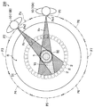
- FIG. 3 is a schematic cross-sectional view of a stereoscopic display.
- 4 is a schematic plan view of the three-dimensional display of FIG.
- FIG. 5 is a perspective view of a light beam controller used in the three-dimensional display of FIGS.
- FIG. 6 is a flowchart showing details of a procedure for creating a shared area and a plurality of unique areas on the conical screen of FIG.
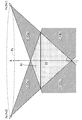
- FIG. 7 is a diagram for explaining a procedure for creating a shared area and a plurality of unique areas.
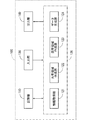
- FIG. 1 is a block diagram showing a configuration of a stereoscopic image production support apparatus according to the present embodiment.
- FIG. 2 is a flowchart showing the overall operation of the stereoscopic image production support apparatus of FIG.
- FIG. 8 is a diagram for explaining a procedure for creating a shared area and a plurality of unique areas.
- FIG. 9 is a diagram for explaining a procedure for creating a shared area and a plurality of unique areas.
- FIG. 10 is a diagram for explaining a procedure for creating a shared area and a plurality of unique areas.
- FIG. 11 is a diagram for explaining a procedure for creating a unique area corresponding to an adjacent occupied area.
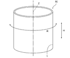
- FIG. 12 is a perspective view of the light beam controller in the first modification.
- FIG. 13 is a diagram for explaining a procedure for creating a shared area and a plurality of unique areas on a cylindrical screen.
- FIG. 14 is a diagram for explaining a procedure for creating a shared area and a plurality of unique areas on a cylindrical screen.
- FIG. 15 is a diagram for explaining a procedure for creating a shared area and a plurality of unique areas on a disk-shaped screen.
- FIG. 16 is a diagram for explaining a procedure for creating a shared area and a plurality of unique areas on a disk-shaped screen.
- FIG. 1 is a block diagram showing a configuration of a stereoscopic image production support apparatus according to the present embodiment.
- the stereoscopic image production support apparatus 100 includes a storage unit 110, an arithmetic processing unit 120, an input unit 130, and an output unit 140.
- the storage unit 110 includes a storage device such as a hard disk or a memory card.
- the storage unit 110 stores a stereoscopic image production support program for performing a stereoscopic image production support process and various types of information described below. Details of the stereoscopic image production support program will be described later.
- the storage unit 110 may store external stereoscopic image production software such as a three-dimensional modeler. In this case, a stereoscopic image production support program may be incorporated in the stereoscopic image production software.
- the arithmetic processing unit 120 includes an information acquisition unit 121, a shared region creation unit 122, a unique region creation unit 123, and a data generation unit 124.
- the arithmetic processing unit 120 includes, for example, a CPU (Central Processing Unit), a ROM (Read Only Memory), and a RAM (Random Access Memory).
- a system program is stored in the ROM.
- the CPU executes the stereoscopic image production support program stored in the storage unit 110 on the RAM, the functions of the information acquisition unit 121, the shared region creation unit 122, the unique region creation unit 123, and the data generation unit 124 are realized. .
- the information acquisition unit 121 acquires screen information and viewing zone information described later.
- the shared area creation unit 122 creates a shared area described later.
- the unique area creation unit 123 creates a unique area described later.
- the data generation unit 124 generates shared area data and unique area data and supplies the generated shared area data and unique area data to the output unit 140.
- the input unit 130 includes a pointing device such as a mouse and a keyboard, for example.
- the manufacturer of the stereoscopic display uses the input unit 130 to input information to be described later to the arithmetic processing unit 120 in advance.
- the input unit 130 may include a reading device that can read data from an external storage medium such as a CD (compact disk) or a RAM, and may include an interface that can be connected to the Internet. In this case, the input unit 130 can acquire information stored in advance in an external storage medium or information transmitted from the Internet and input the information to the arithmetic processing unit 120.
- the output unit 140 includes a data output circuit and an image display device.
- the output unit 140 outputs various data to be described later from the data output circuit, and displays an image based on the various data on the image display device.
- the image display device for example, a liquid crystal display panel, a plasma display panel, or an organic EL (electroluminescence) panel is used.
- the output unit 140 may output various data to, for example, an external stereoscopic image production apparatus, or may output to a storage medium such as a CD (compact disc) or a DVD (digital versatile disc). Alternatively, the output unit 140 may transmit various data to an external stereoscopic image production apparatus by wired communication or wireless communication.
- a storage medium such as a CD (compact disc) or a DVD (digital versatile disc).
- the output unit 140 may transmit various data to an external stereoscopic image production apparatus by wired communication or wireless communication.
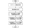
- FIG. 2 is a flowchart showing an overall schematic operation of the stereoscopic image production support device 100 of FIG.
- a stereoscopic display having only horizontal parallax is targeted.
- the stereoscopic image produced by the stereoscopic image production support device 100 is only a shared stereoscopic image that can be viewed by an observer present at an arbitrary position in the viewing area and an observer present at a specific position in the viewing area. Includes a unique stereoscopic image that can be visually recognized.
- the presence of an observer at a certain position on the viewing area means that the observer's eyes are present at a certain position on the viewing area.
- the manufacturer of the stereoscopic display inputs screen information in advance using the input unit 130.
- Screen information is information regarding the shape and dimensions of the screen of the three-dimensional display.
- the screen information is represented by various parameters such as the position of a plurality of portions of the screen, the shape and size of a specific portion.
- the screen is a surface that generates a plurality of light rays for presenting a stereoscopic image in space.
- the positions of a plurality of portions of the screen may be expressed in a real world coordinate system.
- the arithmetic processing unit 120 acquires the input screen information (step S1).
- the manufacturer of the stereoscopic display inputs the viewing zone information in advance using the input unit 130.
- the viewing zone information is information indicating the viewing zone assumed by the observer and the relative positional relationship between the viewing zone and the screen of the stereoscopic display.
- the viewing area is a set of the viewpoints of the observer, and includes a plurality of occupied areas assigned to the plurality of observers.
- the viewing zone may be expressed in a real world coordinate system.
- the viewing zone may be represented by coordinates relative to the screen of the stereoscopic display.
- the arithmetic processing unit 120 acquires the input viewing zone information (step S2).
- the arithmetic processing unit 120 creates a shared area and a plurality of unique areas based on the acquired screen information and viewing area information (step S3).
- the shared area is an area in which a shared stereoscopic image is to be placed when a stereoscopic image creator creates a stereoscopic image using stereoscopic image production software or a stereoscopic image production apparatus.
- Each unique area is an area in which any one of the unique stereoscopic images is to be placed when the creator of the stereoscopic image produces a stereoscopic image using the stereoscopic image production software or the stereoscopic image production apparatus.
- the plurality of unique areas are provided corresponding to the plurality of occupied areas of the viewing area so as not to overlap with the shared area. In the present embodiment, a plurality of unique areas are created, but one unique area may be created.
- the shared stereoscopic image is presented on the stereoscopic display by arranging the shared stereoscopic image in the shared area.
- the observer can stereoscopically view the shared stereoscopic image without any sense of incongruity from any position in the viewing zone.
- the unique stereoscopic image is presented by the stereoscopic display by arranging the unique stereoscopic image in any of the unique areas. An observer present in the occupied area corresponding to the unique area can stereoscopically view the unique stereoscopic image from any position in the occupied area without any sense of incongruity. An observer present in another occupied area cannot visually recognize the unique stereoscopic image. A detailed method for creating the shared area and the unique area will be described later.
- the arithmetic processing unit 120 generates shared area data indicating the shape and size of the created shared area, and also generates a plurality of unique area data respectively indicating the shape and size of the created unique areas (Ste S4). Further, the arithmetic processing unit 120 outputs the shared area data and the plurality of unique area data to the output unit 140 (step S5). Thereby, an image indicating the shared area is displayed on the image display device based on the shared area data. Further, based on the plurality of unique area data, an image indicating the plurality of unique areas is displayed on the image display device.
- the stereoscopic image creator displays a shared stereoscopic image produced using the stereoscopic image production software on the image display device. It can be easily arranged in the image of the shared area. Similarly, a stereoscopic image producer can easily place a unique stereoscopic image produced using stereoscopic image production software in an image of any unique area displayed on the image display device.
- the stereoscopic image production support program When the stereoscopic image production support program is incorporated in the stereoscopic image production software, the shared area data and the plurality of unique area data generated by the arithmetic processing unit 120 are given to the stereoscopic image production software. Thereby, using the display function of the stereoscopic image production software, the image of the shared area based on the shared area data and the image of the unique area based on each of the plurality of unique area data are displayed on the image display device.
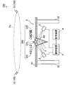
- FIG. 3 is a schematic cross-sectional view of a stereoscopic display.
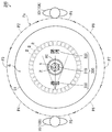
- FIG. 4 is a schematic plan view of the stereoscopic display 200 of FIG.
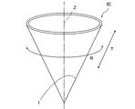
- FIG. 5 is a perspective view of a light beam controller RC used in the three-dimensional display 200 of FIGS. 3 and 4.
- the stereoscopic display 200 includes a screen 1, a plurality of light generators 2, a control device 3, and a storage device 4.
- the screen 1 is formed on the inner peripheral surface of the conical light beam controller RC.
- Each light generator 2 is, for example, a scanning projector.
- the three-dimensional display 200 of FIGS. 3 and 4 is provided on the table 5.
- the table 5 includes a top plate 51 and a plurality of legs 52.
- the top plate 51 has a circular hole.
- the light beam controller RC has a conical shape that is rotationally symmetric about the vertical axis Z.
- the bottom of the light beam controller RC is open.
- the light beam controller RC is formed so that the incident light beam is diffused and transmitted in the ridge line direction T, and is transmitted without being diffused in the circumferential direction R around the axis Z.
- the light beam controller RC is fitted into the circular hole of the top plate 51 so that the bottom opening faces upward.
- An observer 10 around the table 5 can observe the inner peripheral surface of the light beam controller RC from obliquely above the top plate 51 of the table 5.
- the two observers 10 are called observers 10A and 10B, respectively. Assume that the observer 10A is good at reading Japanese and the observer 10B is good at reading English.
- the viewing zone Ps is represented by a circumference around the axis Z.
- the viewing area Ps has a plurality of (8 in the example of FIG. 4) occupation areas P1 to P8 equally divided about the axis Z.
- the occupied areas P1 to P8 are arranged in this order counterclockwise in plan view. Therefore, the occupied area P1 and the occupied area P5 face each other with the axis Z interposed therebetween, and the occupied area P2 and the occupied area P6 face each other across the axis Z.
- the occupied area P3 and the occupied area P7 are opposed to each other with the axis Z interposed therebetween, and the occupied area P4 and the occupied area P8 are opposed to each other with the axis Z interposed therebetween.
- the occupied areas P1 to P8 do not overlap each other, but some of the adjacent occupied areas P1 to P8 may overlap each other.
- the observers 10A and 10B exist in the occupied areas P1 and P5, respectively.
- a plurality of light generators 2 are arranged on a circumference centered on the axis Z of the light controller RC.
- the plurality of light generators 2 are provided so as to irradiate the outer peripheral surface of the light controller RC from obliquely below the light controller RC.
- Each light generator 2 emits a light beam and can deflect the light beam in a horizontal plane and a vertical plane. Thereby, each light generator 2 can scan the outer peripheral surface of the light controller RC with a light beam.
- the light beam refers to light represented by a straight line that does not diffuse.
- the storage device 4 stores stereoscopic shape data for presenting the stereoscopic image 300.
- the stereoscopic image 300 includes a shared stereoscopic image 310 that represents a graphic, a unique stereoscopic image 320 that represents a Japanese character string, and a unique stereoscopic image 330 that represents an English character string.
- the control device 3 is composed of a personal computer, for example. The control device 3 controls the plurality of light generators 2 based on the solid shape data stored in the storage device 4. Thereby, the stereoscopic image 300 is presented above the light controller RC.
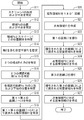
- FIG. 6 is a flowchart showing details of a procedure for creating a shared area and a plurality of unique areas in the conical screen 1 of FIG. 7, 8, 9, and 10 are diagrams for explaining a procedure for creating a shared area and a plurality of unique areas. The details of the procedure for creating the shared area and the plurality of unique areas in step S3 of FIG. 2 will be described below with reference to FIGS.
- the arithmetic processing unit 120 in FIG. 1 specifies the shape and dimensions of the screen 1 based on the display information (step S11). In addition, the arithmetic processing unit 120 specifies the position and size of the viewing zone Ps based on the viewing zone information (step S12). Either the process of step S11 or the process of step S12 may be executed first or may be executed simultaneously. Next, the arithmetic processing unit 120 specifies the relative positional relationship between the viewing zone Ps and the screen 1 (step S13). The relative positional relationship between the identified viewing zone Ps and the screen 1 is used in the following processing.
- the arithmetic processing unit 120 assumes a virtual plane (hereinafter referred to as a virtual plane) PL including the axis Z (step S14).
- the virtual plane PL passes through the center of the occupied area P1 and the center of the occupied area P5 in FIG. 4 in plan view. It is assumed that the viewpoint Pe1 of the observer 10A is located at the intersection between the virtual plane PL and the occupied area P1, and the viewpoint Pe2 of the observer 10B is located at the intersection between the virtual plane PL and the occupied area P5.
- the arithmetic processing unit 120 identifies two viewpoints Pe1 and Pe2 (step S15).
- the arithmetic processing unit 120 identifies the two visually recognizable lines 1a and 1b (step S16). Next, the arithmetic processing unit 120 specifies the positions of the upper end and the lower end of each visible line 1a, 1b (step S17).
- a portion farthest from the viewpoint Pe1 is referred to as an end portion Sm
- a portion closest to the viewpoint Pe1 is referred to as an end portion Sn. That is, of the upper end portion of the screen 1 on the top surface of the top plate 51, the end portion Sm is the portion closest to the viewpoint Pe2, and the end portion Sn is the portion farthest from the viewpoint Pe2.
- the end Sm that is the upper end of the screen 1 can be viewed from the viewpoint Pe1. Therefore, the end Sm is the upper end of the visible line 1a.
- the vertex Sf which is the lower end of the screen 1 may be impossible to visually recognize the vertex Sf which is the lower end of the screen 1 from the viewpoint Pe1 by being blocked by the portion in front of the screen 1. Therefore, when the vertex Sf of the screen 1 cannot be visually recognized from the viewpoint Pe1, the point Sg where the straight line passing through the viewpoint Pe1 and the end Sn intersects the visible line 1a is the lower end of the visible line 1a. When the vertex Sf of the screen 1 can be visually recognized from the viewpoint Pe1, the vertex Sf is the lower end of the visible line 1a.
- the end Sn is the upper end of the visible line 1b.
- the vertex Sf of the screen 1 cannot be viewed from the viewpoint Pe2
- the point Sh where the straight line passing through the viewpoint Pe2 and the end Sm intersects the visible line 1b is the lower end of the visible line 1b.
- the vertex Sf of the screen 1 can be viewed from the viewpoint Pe2
- the vertex Sf is the lower end of the visible line 1b.
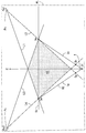
- the arithmetic processing unit 120 specifies the first to fourth straight lines L1 to L4 (step S18).
- the first straight line L1 is a straight line that extends from the viewpoint Pe1 through the upper end of the visible line 1a to the light emitting portion of the light generator 2, and the second straight line L2 extends from the viewpoint Pe1 to the lower end of the visible line 1a. It is a straight line that passes through to the light emitting part of the light generator 2.
- the third straight line L3 is a straight line that extends from the viewpoint Pe2 through the upper end of the visible line 1b to the light emitting part of the light generator 2, and the fourth straight line L4 extends from the viewpoint Pe2 to the lower end of the visible line 1b. It is a straight line that passes through to the light emitting part of the light generator 2.
- the arithmetic processing unit 120 specifies a rectangular area A1 surrounded by the first to fourth straight lines L1 to L4 (step S19).
- the rectangular area A1 is indicated by a dot pattern.
- the arithmetic processing unit 120 rotates the rectangular area A1 by 180 degrees around the axis Z (step S20).
- the arithmetic processing unit 120 creates a three-dimensional area (space) through which the rectangular area A1 passes by rotation as a shared area V1 (step S21).
- the vertex Sf cannot be visually recognized from the viewpoints Pe ⁇ b> 1 and Pe ⁇ b> 2
- the conical outer peripheral surface below the common area V ⁇ b> 1 does not match the screen 1. 8 to 10, the shared area V1 is indicated by a dot pattern.
- the arithmetic processing unit 120 sweeps the first straight line L1 on the circumference of the upper end of the screen 1 with the viewpoint Pe1 as a fulcrum (step S22). Subsequently, the arithmetic processing unit 120 specifies the stereoscopic area surrounded by the swept first straight line L1 as the arrangement area Vx where the stereoscopic image 300 that can be observed from the viewpoint Pe1 is to be arranged (step S23). In FIG. 9, the arrangement region Vx is indicated by the first hatching pattern.
- the arithmetic processing unit 120 creates a part of the arrangement area Vx excluding the shared area V1 as a unique area V2 corresponding to the occupied area P1 (step S24).
- the unique region V2 is indicated by the first hatching pattern.
- the unique area V2 includes a partial area V2a located in front of the screen 1 and a partial area V2b located in the back of the screen 1 when viewed from the viewpoint Pe1.
- the arrangement region Vx is specified by sweeping the first straight line L1, but the present invention is not limited to this.
- the arrangement region Vx may be created by sweeping the second straight line L2.
- the eigen area V2 may be created by sweeping a straight line extending from the viewpoint Pe1 through an arbitrary point at the upper end of the screen 1 to the light emitting portion of the light generator 2. That is, the visible range on the inner surface of the screen 1 from the viewpoint Pe1 may be specified as the visible range, and the arrangement region Vx may be specified based on the visible range.
- the arithmetic processing unit 120 sweeps the third straight line L3 on the circumference of the upper end of the screen 1 with the viewpoint Pe2 as a fulcrum (step S25). Subsequently, the arithmetic processing unit 120 specifies the stereoscopic area surrounded by the swept third straight line L3 as the arrangement area Vy where the stereoscopic image 300 that can be observed from the viewpoint Pe2 is to be arranged (step S26). In FIG. 10, the arrangement region Vy is indicated by a second hatching pattern.
- the arithmetic processing unit 120 creates a part of the arrangement area Vy excluding the shared area V1 as a unique area V3 corresponding to the occupied area P5 (step S27).
- the unique region V3 is indicated by the second hatching pattern.
- the unique area V3 includes a partial area V3a located in front of the screen 1 and a partial area V3b located in the back as viewed from the viewpoint Pe2.
- the unique region V3 is created by sweeping the third straight line L3, but the present invention is not limited to this.
- the unique region V3 may be created by sweeping the fourth straight line L4.
- the eigen area V3 may be created by sweeping a straight line extending from the viewpoint Pe2 through an arbitrary point at the upper end of the screen 1 to the light emitting portion of the light generator 2. That is, the visible range on the inner surface of the screen 1 from the viewpoint Pe2 may be specified as the visible range, and the arrangement region Vy may be specified based on the visible range. Any of the processes of steps S22 to S24 and the processes of steps S25 to S27 may be executed first or simultaneously.
- the shared stereoscopic image 310 When the shared stereoscopic image 310 is presented in the shared area V1 created in this way, the observer 10 can visually recognize the shared stereoscopic image 310 from any position on the viewing area Ps. Therefore, the producer of the stereoscopic image 300 can easily produce the shared stereoscopic image 310 that can be viewed from any position on the viewing area Ps by arranging the shared stereoscopic image 310 in the shared area V1.
- the viewer 10A can visually recognize the unique stereoscopic image 320 from a predetermined position in the occupied region P1, but the viewer 10B The inherent stereoscopic image 320 cannot be visually recognized.
- the unique stereoscopic image 330 is presented in the created unique region V3, the viewer 10B can visually recognize the unique stereoscopic image 330 from a predetermined position in the occupied region P5. The unique stereoscopic image 330 cannot be visually recognized.
- the producer of the stereoscopic image 300 can easily produce the unique stereoscopic image 320 that is visible only to the observer 10A by arranging the unique stereoscopic image 320 in the unique region V2.
- the producer of the stereoscopic image 300 can easily produce the unique stereoscopic image 330 that is visible only to the observer 10B by arranging the unique stereoscopic image 330 in the unique region V3.
- the observer 10A who is good at reading Japanese, can view the Japanese character string-like unique stereoscopic image 320 without visually recognizing the English character string-like unique stereoscopic image 330. Visually check. Therefore, the observer 10A can read the unique stereoscopic image 320 without feeling stress.
- the observer 10B who is good at reading English, visually recognizes the unique 3D image 330 in the form of an English character string without visually recognizing the unique 3D image 320 in the form of a Japanese character string. Therefore, the observer 10B can read the unique stereoscopic image 330 without feeling stress.
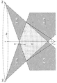
- FIG. 11 is a diagram for explaining a procedure for creating a unique area corresponding to adjacent occupied areas P1 and P2. The example of FIG. 11 is different from the examples of FIGS. 7 to 10 in the following points.
- the observer 10B exists not in the occupied area P5 but in the occupied area P2 adjacent to the occupied area P1.
- the arrangement area Vx and the arrangement area Vy have interference areas Vz that overlap each other.
- the arrangement area Vx corresponding to the viewpoint Pe1 of the observer 10A is indicated by a first hatching pattern
- the arrangement area Vy corresponding to the viewpoint Pe2 of the observer 10B is indicated by a second hatching pattern.
- the interference area Vz is indicated by a dot pattern.
- the shared area V1 overlaps with a part of the interference area Vz.
- Both the observers 10A and 10B can observe the stereoscopic image 300 arranged in the interference region Vz. Therefore, when it is not desired that the observer 10B observe the unique stereoscopic image 320 arranged in the unique region V2, a portion obtained by excluding the interference region Vz together with the shared region V1 from the placement region Vx may be used as the unique region V2. Similarly, when it is not desired for the observer 10A to observe the unique stereoscopic image 330 arranged in the unique region V3, a portion obtained by excluding the interference region Vz together with the shared region V1 from the placement region Vy may be used as the unique region V3.
- the light beam controller RC has a conical shape, but the present invention is not limited to this.
- the light controller RC may have other shapes.
- FIG. 12 is a perspective view of the light beam controller RC in the first modification. As shown in FIG. 12, the light beam controller RC has a cylindrical shape that is rotationally symmetric about the vertical axis Z.
- the screen 1 is formed on the inner peripheral surface of the light beam controller RC.
- the upper and lower bases of the light beam controller RC are open.
- the light beam controller RC is formed so that the incident light beam diffuses and transmits in the vertical direction H and passes straight without being diffused in the circumferential direction R centered on the axis Z.
- the light beam controller RC is fitted into the circular hole of the top plate 51 of FIG. 3 so that the upper bottom opening faces upward.
- the observer 10 around the table 5 in FIG. 4 can observe the inner peripheral surface of the light beam controller RC from obliquely above the top plate 51 of the table 5.
- FIG. 13 and FIG. 14 are diagrams for explaining a procedure for creating a shared area and a plurality of unique areas in the cylindrical screen 1.
- a procedure for creating a shared area and a plurality of unique areas in the cylindrical screen 1 will be described.
- the processing in steps S11 to S16 in the cylindrical screen 1 is the same as the processing in steps S11 to S16 in the conical screen 1.
- the arithmetic processing unit 120 specifies the positions of the upper end and the lower end of each viewable line 1a, 1b.
- the portion farthest from the viewpoint Pe1 is called an end portion So
- the portion closest to the viewpoint Pe1 is called an end portion Sp. That is, in the lower end portion of the screen 1, the end portion So is the portion closest to the viewpoint Pe2, and the end portion Sp is the portion farthest from the viewpoint Pe2.
- the end So of the screen 1 It may be impossible to visually recognize the end So of the screen 1 from the viewpoint Pe1 by being blocked by the portion in front of the screen 1. Therefore, when the end portion So of the screen 1 cannot be visually recognized from the viewpoint Pe1, the point Sg where the straight line passing through the viewpoint Pe1 and the end portion Sn intersects the visible line 1a is the lower end of the visible line 1a. When the end So of the screen 1 can be viewed from the viewpoint Pe1, the end So is the lower end of the viewable line 1a.
- the point Sh where the straight line passing through the viewpoint Pe2 and the end Sm intersects the viewable line 1b is the lower end of the viewable line 1b.
- the end Sp of the screen 1 can be viewed from the viewpoint Pe2, the end Sp becomes the lower end of the visible line 1b.
- steps S18 to S27 in the cylindrical screen 1 is the same as the processing in steps S18 to S27 in the conical screen 1.
- the shared area V1 and the unique areas V2 and V3 are created.
- FIG. 15 and FIG. 16 are diagrams for explaining a procedure for creating a shared region and a plurality of unique regions on a disk-shaped screen.
- the light beam controller RC having a disk shape is fitted into the circular hole portion of the top plate 51.
- a stereoscopic image is presented above the light controller RC.
- one surface of the light beam controller RC is the screen 1.
- the arithmetic processing unit 120 identifies the two visually recognizable lines 1a and 1b.
- the intersection lines between the screen 1 and the virtual plane PL are the visible lines 1a and 1b. That is, in this example, the visible line 1a and the visible line 1b overlap each other.
- the arithmetic processing unit 120 specifies the positions of the upper end and the lower end of each visible line 1a, 1b.
- the visible lines 1a and 1b are horizontal. Therefore, it is considered that one end of the visible line 1a corresponds to the upper end of the visible line 1a, and the other end of the visible line 1a corresponds to the lower end of the visible line 1a.
- one end of the visible line 1b is considered to correspond to the upper end of the visible line 1b, and the other end of the visible line 1b is considered to correspond to the lower end of the visible line 1b.
- one end of the visible line 1a and the other end of the visible line 1b are located at the end Sm of the screen 1. Further, the other end of the visible line 1 a and one end of the visible line 1 b are located at the end Sn of the screen 1.
- steps S18 to S27 on the disk-shaped screen 1 is the same as the processing of steps S18 to S27 on the conical screen 1.
- the shared area V1 and the unique areas V2 and V3 are created.
- the creator of the stereoscopic image 300 recognizes the shared area V1 and the unique areas V2 and V3 based on the data generated by the data generation unit 124. It becomes possible to make it. Thereby, the producer of the stereoscopic image 300 can easily arrange the shared stereoscopic image 310 to be observed at an arbitrary position on the viewing area Ps in the shared area V1 during the production. Further, the producer of the stereoscopic image 300 can easily arrange the unique stereoscopic images 320 and 330 to be observed at the viewpoints Pe1 and Pe2 in the unique regions V2 and V3, respectively.
- the shared stereoscopic image 310 arranged in the shared area V1 can be observed by the observer 10 present at an arbitrary position on the viewing zone Ps.
- the unique stereoscopic image 320 arranged in the unique region V2 can be viewed only by the observer 10A present at the viewpoint Pe1, and cannot be viewed by the observer 10B present at the viewpoint Pe2.
- the unique stereoscopic image 330 arranged in the unique region V3 can be viewed only by the observer 10B present at the viewpoint Pe2, and cannot be viewed by the observer 10A present at the viewpoint Pe1.
- the unique stereoscopic image 320 that can be viewed only by the observer 10A present at the viewpoint Pe1 can be created by a simple process.
- the unique stereoscopic image 330 that can be visually recognized only by the observer 10B present at the viewpoint Pe2 can be created by a simple process.
- the unique area V2 includes partial areas V2a and V2b
- the unique area V3 includes partial areas V3a and V3b. Therefore, the specific regions V2 and V3 can be easily enlarged.
- the creator of the stereoscopic image 300 can display the unique stereoscopic image 320 in front of the shared stereoscopic image 310 by arranging the unique stereoscopic image 320 in the partial region V2a.
- the producer of the stereoscopic image 300 can display the unique stereoscopic image 320 behind the shared stereoscopic image 310 by arranging the unique stereoscopic image 320 in the partial region V2b.
- the creator of the stereoscopic image 300 can display the unique stereoscopic image 330 in front of the shared stereoscopic image 310 by arranging the unique stereoscopic image 330 in the partial region V3a.
- the producer of the stereoscopic image 300 can display the unique stereoscopic image 330 behind the shared stereoscopic image 310 by arranging the unique stereoscopic image 330 in the partial region V3b.
- the axis Z is an example of the central axis
- the screen 1 is an example of a screen
- the stereoscopic display 200 is an example of a stereoscopic display
- the viewing zone Ps is an example of a viewing zone
- the stereoscopic image 300 is. Is an example of a stereoscopic image.
- the stereoscopic image production support device 100 is an example of a stereoscopic image production support device
- the information acquisition unit 121 is an example of an acquisition unit
- the shared region V1 is an example of a shared region
- the shared region creation unit 122 is a shared region creation unit. It is an example.
- the viewpoints Pe1 and Pe2 are examples of the first and second unique positions
- the unique areas V2 and V3 are examples of the first and second unique areas, respectively
- the unique area creation unit 123 is the unique area creation unit. It is an example and the data generation part 124 is an example of a generation part.
- the arrangement areas Vx and Vy are examples of the first and second arrangement areas
- the virtual plane PL is an example of the virtual plane
- the viewpoints Pe1 and Pe2 are examples of the first and second intersections, respectively.
- Possible lines 1a and 1b are examples of first and second visually recognizable lines, respectively.
- the straight lines L1 to L4 are examples of first to fourth lines
- the rectangular area A1 is an example of a plane area
- the first straight line L1 is an example of a fifth line
- the partial areas V2a and V2b are It is an example of the 1st and 2nd partial field, respectively.
- the present invention can be effectively used for various 3D displays for displaying 3D images.
Abstract
In the present invention, information is obtained indicating the shape of a screen, the shape of a viewing region, and the relative positional relationship between the viewing region and the screen. On the basis of the obtained information, a common region is created where a three-dimensional image presented by a three-dimensional display should be arranged such that the three-dimensional image is viewed at any location on the viewing region. On the basis of the obtained information, a unique region is created where a three-dimensional image presented by the three-dimensional display should be arranged such that the three-dimensional image is viewed at a viewpoint on the viewing region. Data indicating the created common region and data indicating the created unique region are generated.
Description
本発明は、立体画像の制作を支援する立体画像制作支援装置に関する。
The present invention relates to a stereoscopic image production support apparatus that supports production of a stereoscopic image.
立体画像を提示する種々の立体ディスプレイが開発されている。特許文献1および2に記載された立体ディスプレイにおいては、錐体形状の光線制御子が配置される。光線制御子の周囲に配置された複数の走査型プロジェクタが、複数の光線からなる光線群を光線制御子の外周面にそれぞれ照射する。光線制御子が各走査型プロジェクタから照射された各光線を周方向において拡散させずに透過させることにより、立体画像が光線制御子の上方および内部に表示される。
A variety of stereoscopic displays that present stereoscopic images have been developed. In the three-dimensional display described in Patent Documents 1 and 2, a cone-shaped light controller is arranged. A plurality of scanning projectors arranged around the light beam controller respectively irradiate the outer peripheral surface of the light beam controller with a group of light beams. The light beam controller transmits each light beam emitted from each scanning projector without diffusing in the circumferential direction, so that a stereoscopic image is displayed above and inside the light beam controller.
特許文献3には、立体ディスプレイに提示される立体画像を制作するための立体画像制作支援装置が記載されている。立体画像制作支援装置は、予め定義された視域、スクリーンの形状およびスクリーンの寸法等により定まる特定の領域を提示する。立体画像の制作者は、提示された領域内に立体画像を配置する。これにより、観察者は視域上のあらゆる位置から立体ディスプレイにより提示される立体画像を視認することができる。
特開2010-32952号公報
特開2011-48273号公報
特開2013-21522号公報
Patent Document 3 describes a stereoscopic image production support apparatus for producing a stereoscopic image presented on a stereoscopic display. The stereoscopic image production support apparatus presents a specific area determined by a predefined viewing area, a screen shape, a screen size, and the like. The creator of the stereoscopic image arranges the stereoscopic image in the presented area. Thereby, the observer can visually recognize the stereoscopic image presented by the stereoscopic display from any position on the viewing area.
JP 2010-32952 A JP 2011-48273 A JP 2013-21522 A
視域上の特定の位置に存在する観察者には視認可能であるが、視域上の他の位置に存在する観察者には視認不可能な立体画像を立体ディスプレイにより提示したい場合がある。このような立体画像を特許文献3の立体画像制作支援装置を用いて作成する場合、立体画像の作成処理における演算時に視域上の位置に応じた条件判定を行う必要がある。そのため、立体画像の作成処理が複雑化する。
There may be a case in which a stereoscopic image that is visible to an observer present at a specific position in the viewing area but cannot be viewed by an observer present at another position on the viewing area may be presented on a stereoscopic display. When such a stereoscopic image is created using the stereoscopic image production support apparatus of Patent Document 3, it is necessary to perform condition determination according to the position in the viewing zone at the time of computation in the stereoscopic image creation process. This complicates stereoscopic image creation processing.
本発明の目的は、視域上の特定の位置に存在する観察者が視認することができ、かつ視域上の他の位置に存在する観察者の視認が制限される立体画像を簡単な処理で作成することを可能にする立体画像制作支援装置を提供することである。
An object of the present invention is to easily process a stereoscopic image that can be visually recognized by an observer existing at a specific position on the viewing area and is restricted from being viewed by an observer present at another position on the viewing area. It is to provide a stereoscopic image production support device that can be created by the above method.
(1)本発明の一局面に従う立体画像制作支援装置は、上下方向の中心軸を取り囲む形状を有するスクリーンを含む立体ディスプレイにより提示されるとともに中心軸を取り囲むように環状に定義された視域において観察可能な立体画像の制作を支援する立体画像制作支援装置であって、スクリーンの形状、視域の形状および視域とスクリーンとの相対的な位置関係を示す情報を取得する取得部と、取得部により取得された情報に基づいて、立体ディスプレイにより提示される立体画像が視域上の任意の位置において観察されるために立体画像を配置すべき領域を共有領域として作成する共有領域作成部と、取得部により取得された情報に基づいて、立体ディスプレイにより提示される立体画像が視域上の予め定められた第1の固有位置において観察されるために立体画像を配置すべき領域を第1の固有領域として作成する固有領域作成部と、共有領域作成部により作成された共有領域を示すデータと固有領域作成部により作成された第1の固有領域を示すデータとを生成する生成部とを備え、固有領域作成部は、第1の固有位置からスクリーンの内面における視認可能な範囲を視認可能範囲として特定し、視認可能範囲に基づいて第1の固有位置から観察可能な立体画像を配置すべき領域を第1の配置領域として特定し、第1の配置領域のうち共有領域作成部により作成される共有領域を除外した部分を第1の固有領域として作成する。
(1) A stereoscopic image production support device according to an aspect of the present invention is presented by a stereoscopic display including a screen having a shape surrounding a central axis in the vertical direction, and in a viewing area defined in an annular shape so as to surround the central axis A stereoscopic image production support apparatus that supports production of an observable stereoscopic image, an acquisition unit that acquires information indicating a shape of a screen, a shape of a viewing zone, and a relative positional relationship between the viewing zone and the screen, and acquisition A shared region creating unit that creates a region in which a stereoscopic image is to be arranged as a shared region in order for the stereoscopic image presented by the stereoscopic display to be observed at an arbitrary position on the viewing area based on the information acquired by the unit; Based on the information acquired by the acquisition unit, the stereoscopic image presented by the stereoscopic display is at a predetermined first specific position on the viewing zone. A unique area creation unit that creates a region where a stereoscopic image is to be placed as a first unique area, and data indicating the shared area created by the shared area creation unit and the unique area creation unit. A generation unit that generates data indicating the first unique area, and the unique area creation unit identifies a viewable range on the inner surface of the screen from the first unique position as a viewable range, and sets the viewable range. Based on this, the region where the observable stereoscopic image is to be arranged from the first specific position is specified as the first arrangement region, and the portion of the first arrangement region excluding the shared region created by the shared region creation unit is Created as a first unique area.
この立体画像制作支援装置においては、スクリーンの形状、視域の形状および視域とスクリーンとの相対的な位置関係を示す情報が取得される。取得された情報に基づいて、立体ディスプレイにより提示される立体画像が視域上の任意の位置において観察されるために立体画像を配置すべき共有領域が作成される。また、取得された情報に基づいて、立体ディスプレイにより提示される立体画像が視域上の第1の固有位置において観察されるために立体画像を配置すべき第1の固有領域が作成される。作成された共有領域を示すデータと第1の固有領域を示すデータとが生成される。
In this stereoscopic image production support apparatus, information indicating the shape of the screen, the shape of the viewing zone, and the relative positional relationship between the viewing zone and the screen is acquired. Based on the acquired information, a shared area in which the stereoscopic image is to be arranged is created in order to observe the stereoscopic image presented by the stereoscopic display at an arbitrary position on the viewing area. In addition, based on the acquired information, a first unique area in which the stereoscopic image is to be arranged is created in order for the stereoscopic image presented by the stereoscopic display to be observed at the first unique position on the viewing area. Data indicating the created shared area and data indicating the first specific area are generated.
第1の固有領域の作成においては、第1の固有位置からスクリーンの内面における視認可能な視認可能範囲が特定される。視認可能範囲に基づいて第1の固有位置から観察可能な立体画像の第1の配置領域が特定される。第1の配置領域のうち共有領域を除外した部分が第1の固有領域として作成される。
In the creation of the first unique area, the visible range on the inner surface of the screen is identified from the first unique position. Based on the visible range, the first arrangement region of the stereoscopic image that can be observed from the first specific position is specified. A portion of the first arrangement area excluding the shared area is created as the first unique area.
この場合、生成部により生成されるデータに基づいて、立体画像の制作者に共有領域および第1の固有領域を認識させることが可能となる。これにより、立体画像の制作者は、立体画像の制作の際に、視域上の任意の位置において観察されるべき立体画像を共有領域内に容易に配置することができる。また、立体画像の制作者は、立体画像の制作の際に、視域上の第1の固有位置において観察されるべき立体画像を第1の固有領域内に容易に配置することができる。
In this case, it becomes possible for the creator of the stereoscopic image to recognize the shared area and the first specific area based on the data generated by the generation unit. Thereby, the producer of the stereoscopic image can easily arrange the stereoscopic image to be observed at an arbitrary position in the viewing area in the shared area when the stereoscopic image is produced. In addition, when producing a stereoscopic image, a producer of a stereoscopic image can easily arrange a stereoscopic image to be observed at the first unique position in the viewing area in the first unique area.
共有領域に配置された立体画像は、視域上の任意の位置に存在する観察者が観察可能である。一方、第1の固有領域に配置された立体画像は、視域上の特定の位置に存在する観察者が視認可能であるが、視域上の他の位置に存在する観察者が視認できるとは限らない。この構成によれば、立体画像の制作の際に複雑な処理を行う必要がない。これにより、視域上の特定の位置に存在する観察者が視認することができ、かつ視域上の他の位置に存在する観察者の視認が制限される立体画像を簡単な処理で作成することができる。
The observer present at an arbitrary position on the viewing zone can observe the stereoscopic image arranged in the shared area. On the other hand, the stereoscopic image arranged in the first unique area can be viewed by an observer present at a specific position in the viewing area, but can be viewed by an observer present at another position in the viewing area. Is not limited. According to this configuration, it is not necessary to perform complicated processing when producing a stereoscopic image. As a result, a three-dimensional image that can be visually recognized by an observer present at a specific position in the viewing area and that is restricted by an observer present at another position on the viewing area is created by simple processing. be able to.
(2)固有領域作成部は、予め定められた第2の固有位置からスクリーンの内面における視認可能な範囲を視認可能範囲として特定し、視認可能範囲に基づいて第2の固有位置から観察可能な立体画像を配置すべき領域を第2の配置領域として特定し、第1の配置領域のうち共有領域および第2の配置領域を除外した部分を第1の固有領域として作成してもよい。この場合、第1の固有位置に存在する観察者が視認することができ、かつ第2の固有位置に存在する観察者が視認することができない立体画像を簡単な処理で作成することができる。
(2) The unique region creation unit identifies a viewable range on the inner surface of the screen from a predetermined second unique position as a viewable range, and can be observed from the second unique position based on the viewable range. The area where the stereoscopic image is to be arranged may be specified as the second arrangement area, and a portion of the first arrangement area excluding the shared area and the second arrangement area may be created as the first unique area. In this case, a stereoscopic image that can be visually recognized by an observer present at the first unique position and cannot be visually recognized by an observer present at the second unique position can be created by a simple process.
(3)固有領域作成部は、第2の配置領域のうち共有領域および第1の配置領域を除外した部分を第2の固有領域として作成し、生成部は、前記固有領域作成部により作成された前記第2の固有領域を示すデータをさらに生成してもよい。この場合、第2の固有位置に存在する観察者が視認することができ、かつ第1の固有位置に存在する観察者が視認することができない立体画像を簡単な処理でさらに作成することができる。
(3) The unique area creation unit creates a part of the second placement area excluding the shared area and the first placement area as a second unique area, and the generation unit is created by the unique area creation unit. Further, data indicating the second unique area may be further generated. In this case, a three-dimensional image that can be visually recognized by an observer present at the second unique position and cannot be visually recognized by an observer present at the first unique position can be further created by simple processing. .
(4)共有領域作成部は、中心軸を含む仮想平面でスクリーンおよび視域を切断し、仮想平面と視域との交点として、中心軸に関して互いに反対側に位置する第1および第2の交点を特定し、仮想平面とスクリーンとの交線として、1または複数の交線を特定し、1または複数の交線のうち第1の交点から視認可能な範囲を第1の視認可能線として特定し、1または複数の交線のうち第2の交点から視認可能な範囲を第2の視認可能線として特定し、第1の交点から第1の視認可能線の一端を通って直線状に延びる第1の線、第1の交点を通って第1の視認可能線の他端を通って直線状に延びる第2の線、第2の交点から第2の視認可能線の一端を通って直線状に延びる第3の線、第2の交点から第2の視認可能線の他端を通って直線状に延びる第4の線により囲まれる平面領域を作成し、平面領域を中心軸を中心として回転させることにより平面領域が通過した領域を共有領域として作成してもよい。この場合、共有領域を容易に作成することができる。
(4) The shared area creation unit cuts the screen and the viewing area at a virtual plane including the central axis, and the first and second intersections located on opposite sides with respect to the central axis as the intersection between the virtual plane and the viewing area Identify one or more intersection lines as the intersection line between the virtual plane and the screen, and specify the range visible from the first intersection point as the first visible line among the one or more intersection lines And the range which can be visually recognized from the 2nd intersection among a 1 or a plurality of intersection lines is specified as the 2nd visible line, and it extends in a straight line through the end of the 1st visible line from the 1st intersection. A first line, a second line extending linearly through the other end of the first viewable line through the first intersection, and a straight line from the second intersection through one end of the second viewable line A third line extending in a straight line, from the second intersection point through the other end of the second visible line to a straight line Create a plane region surrounded by the building fourth line, may create a space in which the planar region passed by rotating the planar area around the central axis as a common area. In this case, the shared area can be easily created.
(5)固有領域作成部は、第1の固有位置からスクリーンの一端の任意の部分を通って直線状に延びる第5の線を特定し、第1の固有位置を支点として第5の線をスクリーンの一端上で掃引することにより第5の線により囲まれる領域を第1の配置領域として特定してもよい。この場合、第1の配置領域を容易に特定することができる。
(5) The unique region creation unit specifies a fifth line that extends linearly from an arbitrary part of one end of the screen from the first unique position, and uses the first unique position as a fulcrum to determine the fifth line. A region surrounded by the fifth line may be specified as the first arrangement region by sweeping on one end of the screen. In this case, the first arrangement area can be easily specified.
(6)第1の固有領域は、第1の固有位置から見てスクリーンよりも手前に配置される第1の部分領域と、固有位置から見てスクリーンよりも奥に配置される第2の部分領域とを含んでもよい。この場合、第1の固有領域を容易に大型化することができる。また、スクリーンよりも手前に配置させたい立体画像をスクリーンよりも手前に配置し、スクリーンよりも奥に配置させたい立体画像をスクリーンよりも奥に配置することが可能になる。
(6) The first unique area includes a first partial area disposed in front of the screen when viewed from the first unique position, and a second part disposed behind the screen as viewed from the unique position. Region. In this case, the first unique area can be easily enlarged. Further, it is possible to arrange a stereoscopic image to be arranged in front of the screen in front of the screen and arrange a stereoscopic image to be arranged in the back of the screen behind the screen.
本発明によれば、視域上の特定の位置に存在する観察者のみが視認することができる立体画像を簡単な処理で作成することができる。
According to the present invention, it is possible to create a stereoscopic image that can be viewed only by an observer present at a specific position in the viewing zone by a simple process.
(1)立体画像制作支援装置の全体構成
以下、本発明の一実施の形態に係る立体画像制作支援装置について図面を参照しながら説明する。本実施の形態に係る立体画像制作支援装置は、立体ディスプレイにより提示される立体画像の制作を支援する。図1は、本実施の形態に係る立体画像制作支援装置の構成を示すブロック図である。図1に示すように、立体画像制作支援装置100は、記憶部110、演算処理部120、入力部130および出力部140を含む。 (1) Overall Configuration of Stereoscopic Image Production Support Device Hereinafter, a stereoscopic image production support device according to an embodiment of the present invention will be described with reference to the drawings. The stereoscopic image production support apparatus according to the present embodiment supports the production of a stereoscopic image presented by a stereoscopic display. FIG. 1 is a block diagram showing a configuration of a stereoscopic image production support apparatus according to the present embodiment. As illustrated in FIG. 1, the stereoscopic imageproduction support apparatus 100 includes a storage unit 110, an arithmetic processing unit 120, an input unit 130, and an output unit 140.
以下、本発明の一実施の形態に係る立体画像制作支援装置について図面を参照しながら説明する。本実施の形態に係る立体画像制作支援装置は、立体ディスプレイにより提示される立体画像の制作を支援する。図1は、本実施の形態に係る立体画像制作支援装置の構成を示すブロック図である。図1に示すように、立体画像制作支援装置100は、記憶部110、演算処理部120、入力部130および出力部140を含む。 (1) Overall Configuration of Stereoscopic Image Production Support Device Hereinafter, a stereoscopic image production support device according to an embodiment of the present invention will be described with reference to the drawings. The stereoscopic image production support apparatus according to the present embodiment supports the production of a stereoscopic image presented by a stereoscopic display. FIG. 1 is a block diagram showing a configuration of a stereoscopic image production support apparatus according to the present embodiment. As illustrated in FIG. 1, the stereoscopic image
記憶部110は、例えばハードディスクまたはメモリカード等の記憶装置を含む。記憶部110には、立体画像制作支援処理を行う立体画像制作支援プログラムおよび後述する各種情報が記憶される。立体画像制作支援プログラムの詳細は後述する。記憶部110に、3次元モデラ等の外部の立体画像制作ソフトウエアが記憶されてもよい。この場合、立体画像制作支援プログラムが立体画像制作ソフトウエアに組み込まれてもよい。
The storage unit 110 includes a storage device such as a hard disk or a memory card. The storage unit 110 stores a stereoscopic image production support program for performing a stereoscopic image production support process and various types of information described below. Details of the stereoscopic image production support program will be described later. The storage unit 110 may store external stereoscopic image production software such as a three-dimensional modeler. In this case, a stereoscopic image production support program may be incorporated in the stereoscopic image production software.
演算処理部120は、情報取得部121、共有領域作成部122、固有領域作成部123およびデータ生成部124を含む。演算処理部120は、例えばCPU(中央演算処理装置)、ROM(リードオンリーメモリ)およびRAM(ランダムアクセスメモリ)により構成される。ROMにはシステムプログラムが記憶される。CPUが記憶部110に記憶される立体画像制作支援プログラムをRAM上で実行することにより、情報取得部121、共有領域作成部122、固有領域作成部123およびデータ生成部124の機能が実現される。
The arithmetic processing unit 120 includes an information acquisition unit 121, a shared region creation unit 122, a unique region creation unit 123, and a data generation unit 124. The arithmetic processing unit 120 includes, for example, a CPU (Central Processing Unit), a ROM (Read Only Memory), and a RAM (Random Access Memory). A system program is stored in the ROM. When the CPU executes the stereoscopic image production support program stored in the storage unit 110 on the RAM, the functions of the information acquisition unit 121, the shared region creation unit 122, the unique region creation unit 123, and the data generation unit 124 are realized. .
情報取得部121は、後述するスクリーン情報と視域情報とを取得する。共有領域作成部122は、後述する共有領域を作成する。固有領域作成部123は、後述する固有領域を作成する。データ生成部124は、共有領域データおよび固有領域データを生成するとともに、出力部140に与える。
The information acquisition unit 121 acquires screen information and viewing zone information described later. The shared area creation unit 122 creates a shared area described later. The unique area creation unit 123 creates a unique area described later. The data generation unit 124 generates shared area data and unique area data and supplies the generated shared area data and unique area data to the output unit 140.
入力部130は、例えばマウス等のポインティングデバイスおよびキーボードを含む。立体ディスプレイの製造者は、入力部130を用いて後述する情報を予め演算処理部120に入力する。入力部130は、CD(コンパクトディスク)またはRAM等の外部記憶媒体からデータを読み込み可能な読込装置を含んでもよいし、インターネットに接続可能なインターフェイスを含んでもよい。この場合、入力部130は、外部記憶媒体に予め記憶された情報またはインターネットから送信される情報を取得し、演算処理部120に入力することができる。
The input unit 130 includes a pointing device such as a mouse and a keyboard, for example. The manufacturer of the stereoscopic display uses the input unit 130 to input information to be described later to the arithmetic processing unit 120 in advance. The input unit 130 may include a reading device that can read data from an external storage medium such as a CD (compact disk) or a RAM, and may include an interface that can be connected to the Internet. In this case, the input unit 130 can acquire information stored in advance in an external storage medium or information transmitted from the Internet and input the information to the arithmetic processing unit 120.
出力部140は、データ出力回路および画像表示装置を含む。この出力部140は、後述する各種データをデータ出力回路から出力するとともに、各種データに基づく画像を画像表示装置に表示する。画像表示装置としては、例えば液晶ディスプレイパネル、プラズマディスプレイパネルまたは有機EL(エレクトロルミネッセンス)パネルが用いられる。
The output unit 140 includes a data output circuit and an image display device. The output unit 140 outputs various data to be described later from the data output circuit, and displays an image based on the various data on the image display device. As the image display device, for example, a liquid crystal display panel, a plasma display panel, or an organic EL (electroluminescence) panel is used.
出力部140は、各種データを例えば外部の立体画像制作装置に出力してもよく、CD(コンパクトディスク)またはDVD(デジタルバーサタイルディスク)等の記憶媒体に出力してもよい。あるいは、出力部140が有線通信または無線通信により各種データを外部の立体画像制作装置に送信してもよい。
The output unit 140 may output various data to, for example, an external stereoscopic image production apparatus, or may output to a storage medium such as a CD (compact disc) or a DVD (digital versatile disc). Alternatively, the output unit 140 may transmit various data to an external stereoscopic image production apparatus by wired communication or wireless communication.
(2)立体画像制作支援装置の全体の概略動作
図2は、図1の立体画像制作支援装置100の全体の概略動作を示すフローチャートである。本実施の形態では、水平視差のみを有する立体ディスプレイを対象とする。また、立体画像制作支援装置100により制作される立体画像は、視域上の任意の位置に存在する観察者が視認可能な共有立体画像と、視域上の特定の位置に存在する観察者のみが視認可能な固有立体画像とを含む。ここで、視域上のある位置に観察者が存在するとは、視域上のある位置に観察者の眼が存在することを意味する。 (2) Overall Schematic Operation of Stereoscopic Image Production Support Device FIG. 2 is a flowchart showing an overall schematic operation of the stereoscopic imageproduction support device 100 of FIG. In this embodiment, a stereoscopic display having only horizontal parallax is targeted. In addition, the stereoscopic image produced by the stereoscopic image production support device 100 is only a shared stereoscopic image that can be viewed by an observer present at an arbitrary position in the viewing area and an observer present at a specific position in the viewing area. Includes a unique stereoscopic image that can be visually recognized. Here, the presence of an observer at a certain position on the viewing area means that the observer's eyes are present at a certain position on the viewing area.
図2は、図1の立体画像制作支援装置100の全体の概略動作を示すフローチャートである。本実施の形態では、水平視差のみを有する立体ディスプレイを対象とする。また、立体画像制作支援装置100により制作される立体画像は、視域上の任意の位置に存在する観察者が視認可能な共有立体画像と、視域上の特定の位置に存在する観察者のみが視認可能な固有立体画像とを含む。ここで、視域上のある位置に観察者が存在するとは、視域上のある位置に観察者の眼が存在することを意味する。 (2) Overall Schematic Operation of Stereoscopic Image Production Support Device FIG. 2 is a flowchart showing an overall schematic operation of the stereoscopic image
立体ディスプレイの製造者は、入力部130を用いてスクリーン情報を予め入力している。スクリーン情報とは、立体ディスプレイのスクリーンの形状および寸法に関する情報である。スクリーン情報は、スクリーンの複数の部分の位置、特定の部分の形状および寸法等の種々のパラメータで表される。ここで、スクリーンは、空間に立体画像を提示するための複数の光線を発生する面である。例えば、スクリーンの複数の部分の位置は実世界座標系で表されてもよい。演算処理部120は、入力されたスクリーン情報を取得する(ステップS1)。
The manufacturer of the stereoscopic display inputs screen information in advance using the input unit 130. Screen information is information regarding the shape and dimensions of the screen of the three-dimensional display. The screen information is represented by various parameters such as the position of a plurality of portions of the screen, the shape and size of a specific portion. Here, the screen is a surface that generates a plurality of light rays for presenting a stereoscopic image in space. For example, the positions of a plurality of portions of the screen may be expressed in a real world coordinate system. The arithmetic processing unit 120 acquires the input screen information (step S1).
また、立体ディスプレイの製造者は、入力部130を用いて視域情報を予め入力している。視域情報とは、観察者の想定される視域、およびその視域と立体ディスプレイのスクリーンとの相対的な位置関係を示す情報である。ここで、視域は、観察者の視点の集合であり、複数の観察者に割り当てられる複数の占有領域を含む。例えば、視域が実世界座標系で表されてもよい。あるいは、視域が立体ディスプレイのスクリーンに対する相対的な座標で表されてもよい。演算処理部120は、入力された視域情報を取得する(ステップS2)。
In addition, the manufacturer of the stereoscopic display inputs the viewing zone information in advance using the input unit 130. The viewing zone information is information indicating the viewing zone assumed by the observer and the relative positional relationship between the viewing zone and the screen of the stereoscopic display. Here, the viewing area is a set of the viewpoints of the observer, and includes a plurality of occupied areas assigned to the plurality of observers. For example, the viewing zone may be expressed in a real world coordinate system. Alternatively, the viewing zone may be represented by coordinates relative to the screen of the stereoscopic display. The arithmetic processing unit 120 acquires the input viewing zone information (step S2).
次に、演算処理部120は、取得したスクリーン情報および視域情報に基づいて、共有領域および複数の固有領域を作成する(ステップS3)。ここで、共有領域は、立体画像の制作者が立体画像制作ソフトウエアまたは立体画像制作装置により立体画像を制作する際に共有立体画像を配置すべき領域である。各固有領域は、立体画像の制作者が立体画像制作ソフトウエアまたは立体画像制作装置により立体画像を制作する際にいずれかの固有立体画像を配置すべき領域である。複数の固有領域は、共有領域とは重複しないように視域の複数の占有領域にそれぞれ対応して設けられる。なお、本実施の形態においては、複数の固有領域が作成されるが、1つの固有領域が作成されてもよい。
Next, the arithmetic processing unit 120 creates a shared area and a plurality of unique areas based on the acquired screen information and viewing area information (step S3). Here, the shared area is an area in which a shared stereoscopic image is to be placed when a stereoscopic image creator creates a stereoscopic image using stereoscopic image production software or a stereoscopic image production apparatus. Each unique area is an area in which any one of the unique stereoscopic images is to be placed when the creator of the stereoscopic image produces a stereoscopic image using the stereoscopic image production software or the stereoscopic image production apparatus. The plurality of unique areas are provided corresponding to the plurality of occupied areas of the viewing area so as not to overlap with the shared area. In the present embodiment, a plurality of unique areas are created, but one unique area may be created.
共有領域内に共有立体画像を配置することにより、立体ディスプレイにより共有立体画像が提示される。観察者は、視域のどの位置から見ても当該共有立体画像を違和感なく立体視することができる。一方、いずれかの固有領域内に固有立体画像を配置することにより、立体ディスプレイにより固有立体画像が提示される。当該固有領域に対応する占有領域に存在する観察者は、占有領域のどの位置から見ても当該固有立体画像を違和感なく立体視することができる。他の占有領域に存在する観察者は、当該固有立体画像を視認することができない。共有領域および固有領域の詳細な作成方法については後述する。
The shared stereoscopic image is presented on the stereoscopic display by arranging the shared stereoscopic image in the shared area. The observer can stereoscopically view the shared stereoscopic image without any sense of incongruity from any position in the viewing zone. On the other hand, the unique stereoscopic image is presented by the stereoscopic display by arranging the unique stereoscopic image in any of the unique areas. An observer present in the occupied area corresponding to the unique area can stereoscopically view the unique stereoscopic image from any position in the occupied area without any sense of incongruity. An observer present in another occupied area cannot visually recognize the unique stereoscopic image. A detailed method for creating the shared area and the unique area will be described later.
その後、演算処理部120は、作成した共有領域の形状および大きさを示す共有領域データを生成するとともに、作成した複数の固有領域の形状および大きさをそれぞれ示す複数の固有領域データを生成する(ステップS4)。さらに、演算処理部120は、共有領域データおよび複数の固有領域データを出力部140に出力する(ステップS5)。それにより、共有領域データに基づいて、画像表示装置に共有領域を示す画像が表示される。また、複数の固有領域データに基づいて、画像表示装置に複数の固有領域を示す画像が表示される。
Thereafter, the arithmetic processing unit 120 generates shared area data indicating the shape and size of the created shared area, and also generates a plurality of unique area data respectively indicating the shape and size of the created unique areas ( Step S4). Further, the arithmetic processing unit 120 outputs the shared area data and the plurality of unique area data to the output unit 140 (step S5). Thereby, an image indicating the shared area is displayed on the image display device based on the shared area data. Further, based on the plurality of unique area data, an image indicating the plurality of unique areas is displayed on the image display device.
例えば、記憶部110に立体画像制作用ソフトウエアが記憶されている場合には、立体画像の制作者は、立体画像制作用ソフトウエアを用いて制作する共有立体画像を画像表示装置に表示された共有領域の画像内に容易に配置することができる。同様に、立体画像の制作者は、立体画像制作用ソフトウエアを用いて制作する固有立体画像を画像表示装置に表示されたいずれかの固有領域の画像内に容易に配置することができる。
For example, when stereoscopic image production software is stored in the storage unit 110, the stereoscopic image creator displays a shared stereoscopic image produced using the stereoscopic image production software on the image display device. It can be easily arranged in the image of the shared area. Similarly, a stereoscopic image producer can easily place a unique stereoscopic image produced using stereoscopic image production software in an image of any unique area displayed on the image display device.
立体画像制作支援プログラムが立体画像制作ソフトウエアに組み込まれている場合には、演算処理部120により生成された共有領域データおよび複数の固有領域データが立体画像制作ソフトウエアに与えられる。それにより、立体画像制作ソフトウエアの表示機能を用いて共有領域データに基づく共有領域の画像および複数の固有領域データにそれぞれ基づく固有領域の画像が画像表示装置に表示される。
When the stereoscopic image production support program is incorporated in the stereoscopic image production software, the shared area data and the plurality of unique area data generated by the arithmetic processing unit 120 are given to the stereoscopic image production software. Thereby, using the display function of the stereoscopic image production software, the image of the shared area based on the shared area data and the image of the unique area based on each of the plurality of unique area data are displayed on the image display device.
(3)立体ディスプレイの構成
図3は、立体ディスプレイの模式的断面図である。図4は、図3の立体ディスプレイ200の模式的平面図である。図5は、図3および図4の立体ディスプレイ200に用いられる光線制御子RCの斜視図である。 (3) Configuration of stereoscopic display FIG. 3 is a schematic cross-sectional view of a stereoscopic display. FIG. 4 is a schematic plan view of thestereoscopic display 200 of FIG. FIG. 5 is a perspective view of a light beam controller RC used in the three-dimensional display 200 of FIGS. 3 and 4.
図3は、立体ディスプレイの模式的断面図である。図4は、図3の立体ディスプレイ200の模式的平面図である。図5は、図3および図4の立体ディスプレイ200に用いられる光線制御子RCの斜視図である。 (3) Configuration of stereoscopic display FIG. 3 is a schematic cross-sectional view of a stereoscopic display. FIG. 4 is a schematic plan view of the
図3に示すように、立体ディスプレイ200は、スクリーン1、複数の光線発生器2、制御装置3および記憶装置4により構成される。スクリーン1は、円錐形状の光線制御子RCの内周面に形成される。各光線発生器2は、例えば走査型プロジェクタである。図3および図4の立体ディスプレイ200は、テーブル5に設けられる。テーブル5は、天板51および複数の脚52からなる。天板51は円形孔部を有する。
3, the stereoscopic display 200 includes a screen 1, a plurality of light generators 2, a control device 3, and a storage device 4. The screen 1 is formed on the inner peripheral surface of the conical light beam controller RC. Each light generator 2 is, for example, a scanning projector. The three-dimensional display 200 of FIGS. 3 and 4 is provided on the table 5. The table 5 includes a top plate 51 and a plurality of legs 52. The top plate 51 has a circular hole.
図5に示すように、光線制御子RCは、上下方向の軸Zを中心として回転対称な円錐形状を有する。光線制御子RCの底部は開口している。光線制御子RCは、入射した光線が稜線方向Tにおいては拡散して透過しかつ軸Zを中心とする円周方向Rにおいてはほとんど拡散せずに直進して透過するように形成されている。
As shown in FIG. 5, the light beam controller RC has a conical shape that is rotationally symmetric about the vertical axis Z. The bottom of the light beam controller RC is open. The light beam controller RC is formed so that the incident light beam is diffused and transmitted in the ridge line direction T, and is transmitted without being diffused in the circumferential direction R around the axis Z.
図3に示すように、光線制御子RCは、底部開口が上方を向くように天板51の円形孔部に嵌め込まれる。テーブル5の周囲にいる観察者10は、テーブル5の天板51の斜め上方から光線制御子RCの内周面を観察することができる。本例においては、テーブル5の周囲に2人の観察者10が存在する。2人の観察者10をそれぞれ観察者10A,10Bと呼ぶ。観察者10Aは日本語の読解が得意であり、観察者10Bは英語の読解が得意であると仮定する。
As shown in FIG. 3, the light beam controller RC is fitted into the circular hole of the top plate 51 so that the bottom opening faces upward. An observer 10 around the table 5 can observe the inner peripheral surface of the light beam controller RC from obliquely above the top plate 51 of the table 5. In this example, there are two observers 10 around the table 5. The two observers 10 are called observers 10A and 10B, respectively. Assume that the observer 10A is good at reading Japanese and the observer 10B is good at reading English.
図4に示すように、視域Psは軸Zを中心とする円周で表される。視域Psは、軸Zを中心に等分された複数(図4の例では8個)の占有領域P1~P8を有する。占有領域P1~P8は、平面視において反時計周りにこの順で配置される。したがって、占有領域P1と占有領域P5とが軸Zを挟んで対向し、占有領域P2と占有領域P6とが軸Zを挟んで対向する。また、占有領域P3と占有領域P7とが軸Zを挟んで対向し、占有領域P4と占有領域P8とが軸Zを挟んで対向する。本実施の形態においては、占有領域P1~P8は互いに重ならないが、隣り合う占有領域P1~P8の一部が互いに重なってもよい。観察者10A,10Bは、占有領域P1,P5にそれぞれ存在する。
As shown in FIG. 4, the viewing zone Ps is represented by a circumference around the axis Z. The viewing area Ps has a plurality of (8 in the example of FIG. 4) occupation areas P1 to P8 equally divided about the axis Z. The occupied areas P1 to P8 are arranged in this order counterclockwise in plan view. Therefore, the occupied area P1 and the occupied area P5 face each other with the axis Z interposed therebetween, and the occupied area P2 and the occupied area P6 face each other across the axis Z. Further, the occupied area P3 and the occupied area P7 are opposed to each other with the axis Z interposed therebetween, and the occupied area P4 and the occupied area P8 are opposed to each other with the axis Z interposed therebetween. In the present embodiment, the occupied areas P1 to P8 do not overlap each other, but some of the adjacent occupied areas P1 to P8 may overlap each other. The observers 10A and 10B exist in the occupied areas P1 and P5, respectively.
テーブル5の下方には、複数の光線発生器2が光線制御子RCの軸Zを中心とする円周上に配置されている。複数の光線発生器2は、光線制御子RCの斜め下方から光線制御子RCの外周面に光線を照射するように設けられる。各光線発生器2は、光線を出射するとともにその光線を水平面内および垂直面内で偏向させることができる。それにより、各光線発生器2は、光線で光線制御子RCの外周面を走査することができる。ここで、光線とは、拡散しない直線で表される光をいう。
Below the table 5, a plurality of light generators 2 are arranged on a circumference centered on the axis Z of the light controller RC. The plurality of light generators 2 are provided so as to irradiate the outer peripheral surface of the light controller RC from obliquely below the light controller RC. Each light generator 2 emits a light beam and can deflect the light beam in a horizontal plane and a vertical plane. Thereby, each light generator 2 can scan the outer peripheral surface of the light controller RC with a light beam. Here, the light beam refers to light represented by a straight line that does not diffuse.
記憶装置4には、立体画像300を提示するための立体形状データが記憶される。本例では、立体画像300は、図形を表す共有立体画像310と、日本語の文字列を表す固有立体画像320と、英語の文字列を表す固有立体画像330とを含む。制御装置3は、例えばパーソナルコンピュータからなる。制御装置3は、記憶装置4に記憶される立体形状データに基づいて複数の光線発生器2を制御する。それにより、光線制御子RCの上方に立体画像300が提示される。
The storage device 4 stores stereoscopic shape data for presenting the stereoscopic image 300. In this example, the stereoscopic image 300 includes a shared stereoscopic image 310 that represents a graphic, a unique stereoscopic image 320 that represents a Japanese character string, and a unique stereoscopic image 330 that represents an English character string. The control device 3 is composed of a personal computer, for example. The control device 3 controls the plurality of light generators 2 based on the solid shape data stored in the storage device 4. Thereby, the stereoscopic image 300 is presented above the light controller RC.
(4)共有領域および固有領域の作成手順
図6は、図5の円錐形状のスクリーン1における共有領域および複数の固有領域の作成手順の詳細を示すフローチャートである。図7、図8、図9および図10は、共有領域および複数の固有領域の作成手順を説明するための図である。以下、図6~図10を用いて、図2のステップS3における共有領域および複数の固有領域の作成手順の詳細を説明する。 (4) Procedure for Creating Shared Area and Unique Area FIG. 6 is a flowchart showing details of a procedure for creating a shared area and a plurality of unique areas in theconical screen 1 of FIG. 7, 8, 9, and 10 are diagrams for explaining a procedure for creating a shared area and a plurality of unique areas. The details of the procedure for creating the shared area and the plurality of unique areas in step S3 of FIG. 2 will be described below with reference to FIGS.
図6は、図5の円錐形状のスクリーン1における共有領域および複数の固有領域の作成手順の詳細を示すフローチャートである。図7、図8、図9および図10は、共有領域および複数の固有領域の作成手順を説明するための図である。以下、図6~図10を用いて、図2のステップS3における共有領域および複数の固有領域の作成手順の詳細を説明する。 (4) Procedure for Creating Shared Area and Unique Area FIG. 6 is a flowchart showing details of a procedure for creating a shared area and a plurality of unique areas in the
まず、図1の演算処理部120は、ディスプレイ情報に基づいてスクリーン1の形状および寸法を特定する(ステップS11)。また、演算処理部120は、視域情報に基づいて視域Psの位置および寸法を特定する(ステップS12)。ステップS11の処理とステップS12の処理とは、いずれが先に実行されてもよいし、同時に実行されてもよい。次に、演算処理部120は、視域Psとスクリーン1との相対的な位置関係を特定する(ステップS13)。特定された視域Psとスクリーン1との相対的な位置関係は、以下の処理において用いられる。
First, the arithmetic processing unit 120 in FIG. 1 specifies the shape and dimensions of the screen 1 based on the display information (step S11). In addition, the arithmetic processing unit 120 specifies the position and size of the viewing zone Ps based on the viewing zone information (step S12). Either the process of step S11 or the process of step S12 may be executed first or may be executed simultaneously. Next, the arithmetic processing unit 120 specifies the relative positional relationship between the viewing zone Ps and the screen 1 (step S13). The relative positional relationship between the identified viewing zone Ps and the screen 1 is used in the following processing.
演算処理部120は、図7に示すように、軸Zを含む仮想的な平面(以下、仮想平面と呼ぶ。)PLを想定する(ステップS14)。本例では、仮想平面PLは、平面視において図4の占有領域P1の中心および占有領域P5の中心を通る。仮想平面PLと占有領域P1との交点に観察者10Aの視点Pe1が位置し、仮想平面PLと占有領域P5との交点に観察者10Bの視点Pe2が位置することを仮定する。演算処理部120は、2つの視点Pe1,Pe2を特定する(ステップS15)。
As shown in FIG. 7, the arithmetic processing unit 120 assumes a virtual plane (hereinafter referred to as a virtual plane) PL including the axis Z (step S14). In this example, the virtual plane PL passes through the center of the occupied area P1 and the center of the occupied area P5 in FIG. 4 in plan view. It is assumed that the viewpoint Pe1 of the observer 10A is located at the intersection between the virtual plane PL and the occupied area P1, and the viewpoint Pe2 of the observer 10B is located at the intersection between the virtual plane PL and the occupied area P5. The arithmetic processing unit 120 identifies two viewpoints Pe1 and Pe2 (step S15).
また、仮想平面PLとスクリーン1との間には、2つの交線が存在する。視点Pe1から視認可能な一方の交線の範囲を視認可能線1aと呼び、視点Pe2から視認可能な他方の交線の範囲を視認可能線1bと呼ぶ。演算処理部120は、2つの視認可能線1a,1bを特定する(ステップS16)。次に、演算処理部120は、各視認可能線1a,1bの上端および下端の位置を特定する(ステップS17)。
Also, there are two intersecting lines between the virtual plane PL and the screen 1. The range of one intersection line visible from the viewpoint Pe1 is referred to as a visible line 1a, and the other intersection line range visible from the viewpoint Pe2 is referred to as a visible line 1b. The arithmetic processing unit 120 identifies the two visually recognizable lines 1a and 1b (step S16). Next, the arithmetic processing unit 120 specifies the positions of the upper end and the lower end of each visible line 1a, 1b (step S17).
ここで、天板51の上面上におけるスクリーン1の上端部のうち、視点Pe1から最も遠い部分を端部Smと呼び、視点Pe1から最も近い部分を端部Snと呼ぶ。すなわち、天板51の上面上におけるスクリーン1の上端部のうち、端部Smは視点Pe2から最も近い部分であり、端部Snは視点Pe2から最も遠い部分である。視点Pe1からスクリーン1の上端である端部Smを視認することが可能である。そのため、端部Smが視認可能線1aの上端となる。
Here, in the upper end portion of the screen 1 on the top surface of the top plate 51, a portion farthest from the viewpoint Pe1 is referred to as an end portion Sm, and a portion closest to the viewpoint Pe1 is referred to as an end portion Sn. That is, of the upper end portion of the screen 1 on the top surface of the top plate 51, the end portion Sm is the portion closest to the viewpoint Pe2, and the end portion Sn is the portion farthest from the viewpoint Pe2. The end Sm that is the upper end of the screen 1 can be viewed from the viewpoint Pe1. Therefore, the end Sm is the upper end of the visible line 1a.
一方、スクリーン1の手前の部分で遮られることにより、視点Pe1からスクリーン1の下端である頂点Sfを視認することは不可能である場合がある。そのため、視点Pe1からスクリーン1の頂点Sfを視認できない場合には、視点Pe1および端部Snを通る直線が視認可能線1aと交差する点Sgが視認可能線1aの下端となる。視点Pe1からスクリーン1の頂点Sfを視認できる場合には、頂点Sfが視認可能線1aの下端となる。
On the other hand, it may be impossible to visually recognize the vertex Sf which is the lower end of the screen 1 from the viewpoint Pe1 by being blocked by the portion in front of the screen 1. Therefore, when the vertex Sf of the screen 1 cannot be visually recognized from the viewpoint Pe1, the point Sg where the straight line passing through the viewpoint Pe1 and the end Sn intersects the visible line 1a is the lower end of the visible line 1a. When the vertex Sf of the screen 1 can be visually recognized from the viewpoint Pe1, the vertex Sf is the lower end of the visible line 1a.
同様に、端部Snが視認可能線1bの上端となる。視点Pe2からスクリーン1の頂点Sfを視認できない場合には、視点Pe2および端部Smを通る直線が視認可能線1bと交差する点Shが視認可能線1bの下端となる。一方、視点Pe2からスクリーン1の頂点Sfを視認できる場合には、頂点Sfが視認可能線1bの下端となる。
Similarly, the end Sn is the upper end of the visible line 1b. When the vertex Sf of the screen 1 cannot be viewed from the viewpoint Pe2, the point Sh where the straight line passing through the viewpoint Pe2 and the end Sm intersects the visible line 1b is the lower end of the visible line 1b. On the other hand, when the vertex Sf of the screen 1 can be viewed from the viewpoint Pe2, the vertex Sf is the lower end of the visible line 1b.
その後、演算処理部120は、第1~第4の直線L1~L4を特定する(ステップS18)。第1の直線L1は、視点Pe1から視認可能線1aの上端を通って光線発生器2の光出射部まで延びる直線であり、第2の直線L2は、視点Pe1から視認可能線1aの下端を通って光線発生器2の光出射部まで延びる直線である。第3の直線L3は、視点Pe2から視認可能線1bの上端を通って光線発生器2の光出射部まで延びる直線であり、第4の直線L4は、視点Pe2から視認可能線1bの下端を通って光線発生器2の光出射部まで延びる直線である。
After that, the arithmetic processing unit 120 specifies the first to fourth straight lines L1 to L4 (step S18). The first straight line L1 is a straight line that extends from the viewpoint Pe1 through the upper end of the visible line 1a to the light emitting portion of the light generator 2, and the second straight line L2 extends from the viewpoint Pe1 to the lower end of the visible line 1a. It is a straight line that passes through to the light emitting part of the light generator 2. The third straight line L3 is a straight line that extends from the viewpoint Pe2 through the upper end of the visible line 1b to the light emitting part of the light generator 2, and the fourth straight line L4 extends from the viewpoint Pe2 to the lower end of the visible line 1b. It is a straight line that passes through to the light emitting part of the light generator 2.
次に、演算処理部120は、第1~第4の直線L1~L4により囲まれる矩形領域A1を特定する(ステップS19)。図7においては、矩形領域A1がドットパターンで示される。続いて、演算処理部120は、軸Zを中心に矩形領域A1を180°回転させる(ステップS20)。その後、演算処理部120は、図8に示すように、回転により矩形領域A1が通過した立体領域(空間)を共有領域V1として作成する(ステップS21)。視点Pe1,Pe2から頂点Sfを視認できない場合、共有領域V1の下部の円錐状の外周面はスクリーン1と一致しない。図8~図10においては、共有領域V1がドットパターンで示される。
Next, the arithmetic processing unit 120 specifies a rectangular area A1 surrounded by the first to fourth straight lines L1 to L4 (step S19). In FIG. 7, the rectangular area A1 is indicated by a dot pattern. Subsequently, the arithmetic processing unit 120 rotates the rectangular area A1 by 180 degrees around the axis Z (step S20). Thereafter, as shown in FIG. 8, the arithmetic processing unit 120 creates a three-dimensional area (space) through which the rectangular area A1 passes by rotation as a shared area V1 (step S21). When the vertex Sf cannot be visually recognized from the viewpoints Pe <b> 1 and Pe <b> 2, the conical outer peripheral surface below the common area V <b> 1 does not match the screen 1. 8 to 10, the shared area V1 is indicated by a dot pattern.
次に、演算処理部120は、図9に示すように、視点Pe1を支点として第1の直線L1をスクリーン1の上端の円周上で掃引する(ステップS22)。続いて、演算処理部120は、掃引された第1の直線L1により囲まれる立体領域を視点Pe1から観察可能な立体画像300を配置すべき配置領域Vxとして特定する(ステップS23)。図9においては、配置領域Vxが第1のハッチングパターンで示される。
Next, as shown in FIG. 9, the arithmetic processing unit 120 sweeps the first straight line L1 on the circumference of the upper end of the screen 1 with the viewpoint Pe1 as a fulcrum (step S22). Subsequently, the arithmetic processing unit 120 specifies the stereoscopic area surrounded by the swept first straight line L1 as the arrangement area Vx where the stereoscopic image 300 that can be observed from the viewpoint Pe1 is to be arranged (step S23). In FIG. 9, the arrangement region Vx is indicated by the first hatching pattern.
その後、演算処理部120は、配置領域Vxのうち、共有領域V1を除外した部分を占有領域P1に対応する固有領域V2として作成する(ステップS24)。図8においては、固有領域V2が第1のハッチングパターンで示される。固有領域V2は、視点Pe1から見て、スクリーン1の手前に位置する部分領域V2aとスクリーン1の奥に位置する部分領域V2bとを含む。
Thereafter, the arithmetic processing unit 120 creates a part of the arrangement area Vx excluding the shared area V1 as a unique area V2 corresponding to the occupied area P1 (step S24). In FIG. 8, the unique region V2 is indicated by the first hatching pattern. The unique area V2 includes a partial area V2a located in front of the screen 1 and a partial area V2b located in the back of the screen 1 when viewed from the viewpoint Pe1.
ステップS22,S23において、第1の直線L1が掃引されることにより配置領域Vxが特定されるが、本発明はこれに限定されない。第2の直線L2が掃引されることにより配置領域Vxが作成されてもよい。あるいは、視点Pe1からスクリーン1の上端の任意の点を通って光線発生器2の光出射部まで延びる直線が掃引されることにより固有領域V2が作成されてもよい。すなわち、視点Pe1からスクリーン1の内面における視認可能な範囲が視認可能範囲として特定され、視認可能範囲に基づいて配置領域Vxが特定されてもよい。
In Steps S22 and S23, the arrangement region Vx is specified by sweeping the first straight line L1, but the present invention is not limited to this. The arrangement region Vx may be created by sweeping the second straight line L2. Alternatively, the eigen area V2 may be created by sweeping a straight line extending from the viewpoint Pe1 through an arbitrary point at the upper end of the screen 1 to the light emitting portion of the light generator 2. That is, the visible range on the inner surface of the screen 1 from the viewpoint Pe1 may be specified as the visible range, and the arrangement region Vx may be specified based on the visible range.
同様に、演算処理部120は、図10に示すように、視点Pe2を支点として第3の直線L3をスクリーン1の上端の円周上で掃引する(ステップS25)。続いて、演算処理部120は、掃引された第3の直線L3により囲まれる立体領域を視点Pe2から観察可能な立体画像300を配置すべき配置領域Vyとして特定する(ステップS26)。図10においては、配置領域Vyが第2のハッチングパターンで示される。
Similarly, as shown in FIG. 10, the arithmetic processing unit 120 sweeps the third straight line L3 on the circumference of the upper end of the screen 1 with the viewpoint Pe2 as a fulcrum (step S25). Subsequently, the arithmetic processing unit 120 specifies the stereoscopic area surrounded by the swept third straight line L3 as the arrangement area Vy where the stereoscopic image 300 that can be observed from the viewpoint Pe2 is to be arranged (step S26). In FIG. 10, the arrangement region Vy is indicated by a second hatching pattern.
その後、演算処理部120は、配置領域Vyのうち、共有領域V1を除外した部分を占有領域P5に対応する固有領域V3として作成する(ステップS27)。図8においては、固有領域V3が第2のハッチングパターンで示される。固有領域V3は、視点Pe2から見て、スクリーン1の手前に位置する部分領域V3aと奥に位置する部分領域V3bとを含む。
Thereafter, the arithmetic processing unit 120 creates a part of the arrangement area Vy excluding the shared area V1 as a unique area V3 corresponding to the occupied area P5 (step S27). In FIG. 8, the unique region V3 is indicated by the second hatching pattern. The unique area V3 includes a partial area V3a located in front of the screen 1 and a partial area V3b located in the back as viewed from the viewpoint Pe2.
ステップS25,S26において、第3の直線L3が掃引されることにより固有領域V3が作成されるが、本発明はこれに限定されない。第4の直線L4が掃引されることにより固有領域V3が作成されてもよい。あるいは、視点Pe2からスクリーン1の上端の任意の点を通って光線発生器2の光出射部まで延びる直線が掃引されることにより固有領域V3が作成されてもよい。すなわち、視点Pe2からスクリーン1の内面における視認可能な範囲が視認可能範囲として特定され、視認可能範囲に基づいて配置領域Vyが特定されてもよい。ステップS22~S24の処理とステップS25~S27の処理とは、いずれが先に実行されてもよいし、同時に実行されてもよい。
In Steps S25 and S26, the unique region V3 is created by sweeping the third straight line L3, but the present invention is not limited to this. The unique region V3 may be created by sweeping the fourth straight line L4. Alternatively, the eigen area V3 may be created by sweeping a straight line extending from the viewpoint Pe2 through an arbitrary point at the upper end of the screen 1 to the light emitting portion of the light generator 2. That is, the visible range on the inner surface of the screen 1 from the viewpoint Pe2 may be specified as the visible range, and the arrangement region Vy may be specified based on the visible range. Any of the processes of steps S22 to S24 and the processes of steps S25 to S27 may be executed first or simultaneously.
このようにして作成された共有領域V1内に共有立体画像310が提示されると、観察者10はその共有立体画像310を視域Ps上のあらゆる位置から視認することができる。そのため、立体画像300の制作者は、共有立体画像310を共有領域V1内に配置することにより、視域Ps上のあらゆる位置から視認可能な共有立体画像310を容易に制作することができる。
When the shared stereoscopic image 310 is presented in the shared area V1 created in this way, the observer 10 can visually recognize the shared stereoscopic image 310 from any position on the viewing area Ps. Therefore, the producer of the stereoscopic image 300 can easily produce the shared stereoscopic image 310 that can be viewed from any position on the viewing area Ps by arranging the shared stereoscopic image 310 in the shared area V1.
一方、作成された固有領域V2内に固有立体画像320が提示されると、観察者10Aはその固有立体画像320を占有領域P1の所定の位置から視認することができるが、観察者10Bは、当該固有立体画像320を視認することができない。同様に、作成された固有領域V3内に固有立体画像330が提示されると、観察者10Bはその固有立体画像330を占有領域P5の所定の位置から視認することができるが、観察者10Aは、当該固有立体画像330を視認することができない。
On the other hand, when the unique stereoscopic image 320 is presented in the created unique region V2, the viewer 10A can visually recognize the unique stereoscopic image 320 from a predetermined position in the occupied region P1, but the viewer 10B The inherent stereoscopic image 320 cannot be visually recognized. Similarly, when the unique stereoscopic image 330 is presented in the created unique region V3, the viewer 10B can visually recognize the unique stereoscopic image 330 from a predetermined position in the occupied region P5. The unique stereoscopic image 330 cannot be visually recognized.
このように、立体画像300の制作者は、固有立体画像320を固有領域V2内に配置することにより、観察者10Aのみが視認可能な固有立体画像320を容易に制作することが可能になる。また、立体画像300の制作者は、固有立体画像330を固有領域V3内に配置することにより、観察者10Bのみが視認可能な固有立体画像330を容易に制作することが可能になる。
Thus, the producer of the stereoscopic image 300 can easily produce the unique stereoscopic image 320 that is visible only to the observer 10A by arranging the unique stereoscopic image 320 in the unique region V2. In addition, the producer of the stereoscopic image 300 can easily produce the unique stereoscopic image 330 that is visible only to the observer 10B by arranging the unique stereoscopic image 330 in the unique region V3.
さらに、上記の構成によれば、日本語の読解が得意である観察者10Aは、英語の文字列状の固有立体画像330を視認することなく、日本語の文字列状の固有立体画像320を視認する。そのため、観察者10Aは、ストレスを感じることなく固有立体画像320を読解することができる。同様に、英語の読解が得意である観察者10Bは、日本語の文字列状の固有立体画像320を視認することなく、英語の文字列状の固有立体画像330を視認する。そのため、観察者10Bは、ストレスを感じることなく固有立体画像330を読解することができる。
Furthermore, according to the above configuration, the observer 10A, who is good at reading Japanese, can view the Japanese character string-like unique stereoscopic image 320 without visually recognizing the English character string-like unique stereoscopic image 330. Visually check. Therefore, the observer 10A can read the unique stereoscopic image 320 without feeling stress. Similarly, the observer 10B, who is good at reading English, visually recognizes the unique 3D image 330 in the form of an English character string without visually recognizing the unique 3D image 320 in the form of a Japanese character string. Therefore, the observer 10B can read the unique stereoscopic image 330 without feeling stress.
上記の手順においては、占有領域P1,P5にそれぞれ対応する固有領域V2,V3のみが作成されるが、本発明はこれに限定されない。上記の手順と同様の手順により、他の占有領域P2~P4,P6~P8に対応する固有領域の一部または全部が作成されてもよい。図11は、隣り合う占有領域P1,P2に対応する固有領域の作成手順を説明するための図である。図11の例においては、以下の点が図7~図10の例と異なる。
In the above procedure, only the unique areas V2 and V3 corresponding to the occupied areas P1 and P5 are created, but the present invention is not limited to this. A part or all of the unique areas corresponding to the other occupied areas P2 to P4 and P6 to P8 may be created by the same procedure as described above. FIG. 11 is a diagram for explaining a procedure for creating a unique area corresponding to adjacent occupied areas P1 and P2. The example of FIG. 11 is different from the examples of FIGS. 7 to 10 in the following points.
図11に示すように、観察者10Bは占有領域P5ではなく占有領域P1に隣り合う占有領域P2に存在する。この場合、配置領域Vxと配置領域Vyとは、互いに重複する干渉領域Vzを有する。図11においては、観察者10Aの視点Pe1に対応する配置領域Vxが第1のハッチングパターンで示され、観察者10Bの視点Pe2に対応する配置領域Vyが第2のハッチングパターンで示される。また、干渉領域Vzがドットパターンで示される。なお、共有領域V1は干渉領域Vzの一部と重複する。
As shown in FIG. 11, the observer 10B exists not in the occupied area P5 but in the occupied area P2 adjacent to the occupied area P1. In this case, the arrangement area Vx and the arrangement area Vy have interference areas Vz that overlap each other. In FIG. 11, the arrangement area Vx corresponding to the viewpoint Pe1 of the observer 10A is indicated by a first hatching pattern, and the arrangement area Vy corresponding to the viewpoint Pe2 of the observer 10B is indicated by a second hatching pattern. Further, the interference area Vz is indicated by a dot pattern. The shared area V1 overlaps with a part of the interference area Vz.
干渉領域Vzに配置された立体画像300は、観察者10A,10Bの両者が観察可能である。そこで、固有領域V2に配置される固有立体画像320を観察者10Bに観察させたくない場合は、配置領域Vxから共有領域V1とともに干渉領域Vzを除外した部分を固有領域V2としてもよい。同様に、固有領域V3に配置される固有立体画像330を観察者10Aに観察させたくない場合は、配置領域Vyから共有領域V1とともに干渉領域Vzを除外した部分を固有領域V3としてもよい。
Both the observers 10A and 10B can observe the stereoscopic image 300 arranged in the interference region Vz. Therefore, when it is not desired that the observer 10B observe the unique stereoscopic image 320 arranged in the unique region V2, a portion obtained by excluding the interference region Vz together with the shared region V1 from the placement region Vx may be used as the unique region V2. Similarly, when it is not desired for the observer 10A to observe the unique stereoscopic image 330 arranged in the unique region V3, a portion obtained by excluding the interference region Vz together with the shared region V1 from the placement region Vy may be used as the unique region V3.
(5)変形例
(a)第1の変形例
上記実施の形態においては、光線制御子RCは円錐形状を有するが、本発明はこれに限定されない。光線制御子RCは他の形状を有してもよい。図12は、第1の変形例における光線制御子RCの斜視図である。図12に示すように、光線制御子RCは、上下方向の軸Zを中心として回転対称な円筒形状を有する。スクリーン1は、光線制御子RCの内周面に形成される。 (5) Modification (a) First Modification In the above embodiment, the light beam controller RC has a conical shape, but the present invention is not limited to this. The light controller RC may have other shapes. FIG. 12 is a perspective view of the light beam controller RC in the first modification. As shown in FIG. 12, the light beam controller RC has a cylindrical shape that is rotationally symmetric about the vertical axis Z. Thescreen 1 is formed on the inner peripheral surface of the light beam controller RC.
(a)第1の変形例
上記実施の形態においては、光線制御子RCは円錐形状を有するが、本発明はこれに限定されない。光線制御子RCは他の形状を有してもよい。図12は、第1の変形例における光線制御子RCの斜視図である。図12に示すように、光線制御子RCは、上下方向の軸Zを中心として回転対称な円筒形状を有する。スクリーン1は、光線制御子RCの内周面に形成される。 (5) Modification (a) First Modification In the above embodiment, the light beam controller RC has a conical shape, but the present invention is not limited to this. The light controller RC may have other shapes. FIG. 12 is a perspective view of the light beam controller RC in the first modification. As shown in FIG. 12, the light beam controller RC has a cylindrical shape that is rotationally symmetric about the vertical axis Z. The
光線制御子RCの上底部および下底部は開口している。光線制御子RCは、入射した光線が上下方向Hにおいては拡散して透過しかつ軸Zを中心とする円周方向Rにおいては拡散せずに直進して透過するように形成されている。光線制御子RCは、上底部開口が上方を向くように図3の天板51の円形孔部に嵌め込まれる。図4のテーブル5の周囲にいる観察者10は、テーブル5の天板51の斜め上方から光線制御子RCの内周面を観察することができる。
The upper and lower bases of the light beam controller RC are open. The light beam controller RC is formed so that the incident light beam diffuses and transmits in the vertical direction H and passes straight without being diffused in the circumferential direction R centered on the axis Z. The light beam controller RC is fitted into the circular hole of the top plate 51 of FIG. 3 so that the upper bottom opening faces upward. The observer 10 around the table 5 in FIG. 4 can observe the inner peripheral surface of the light beam controller RC from obliquely above the top plate 51 of the table 5.
図13および図14は、円筒形状のスクリーン1における共有領域および複数の固有領域の作成手順を説明するための図である。図6のフローチャートならびに図13および図14を用いて、円筒形状のスクリーン1における共有領域および複数の固有領域の作成手順を説明する。円筒形状のスクリーン1におけるステップS11~S16の処理は、円錐形状のスクリーン1におけるステップS11~S16の処理と同様である。
FIG. 13 and FIG. 14 are diagrams for explaining a procedure for creating a shared area and a plurality of unique areas in the cylindrical screen 1. With reference to the flowchart of FIG. 6 and FIGS. 13 and 14, a procedure for creating a shared area and a plurality of unique areas in the cylindrical screen 1 will be described. The processing in steps S11 to S16 in the cylindrical screen 1 is the same as the processing in steps S11 to S16 in the conical screen 1.
ステップS17の処理において、演算処理部120は、各視認可能線1a,1bの上端および下端の位置を特定する。ここで、スクリーン1の下端部のうち、視点Pe1から最も遠い部分を端部Soと呼び、視点Pe1から最も近い部分を端部Spと呼ぶ。すなわち、スクリーン1の下端部のうち、端部Soは視点Pe2から最も近い部分であり、端部Spは視点Pe2から最も遠い部分である。
In the process of step S17, the arithmetic processing unit 120 specifies the positions of the upper end and the lower end of each viewable line 1a, 1b. Here, in the lower end portion of the screen 1, the portion farthest from the viewpoint Pe1 is called an end portion So, and the portion closest to the viewpoint Pe1 is called an end portion Sp. That is, in the lower end portion of the screen 1, the end portion So is the portion closest to the viewpoint Pe2, and the end portion Sp is the portion farthest from the viewpoint Pe2.
スクリーン1の手前の部分で遮られることにより、視点Pe1からスクリーン1の端部Soを視認することは不可能である場合がある。そのため、視点Pe1からスクリーン1の端部Soを視認できない場合には、視点Pe1および端部Snを通る直線が視認可能線1aと交差する点Sgが視認可能線1aの下端となる。視点Pe1からスクリーン1の端部Soを視認できる場合には、端部Soが視認可能線1aの下端となる。
It may be impossible to visually recognize the end So of the screen 1 from the viewpoint Pe1 by being blocked by the portion in front of the screen 1. Therefore, when the end portion So of the screen 1 cannot be visually recognized from the viewpoint Pe1, the point Sg where the straight line passing through the viewpoint Pe1 and the end portion Sn intersects the visible line 1a is the lower end of the visible line 1a. When the end So of the screen 1 can be viewed from the viewpoint Pe1, the end So is the lower end of the viewable line 1a.
同様に、視点Pe2からスクリーン1の端部Spを視認できない場合には、視点Pe2および端部Smを通る直線が視認可能線1bと交差する点Shが視認可能線1bの下端となる。一方、視点Pe2からスクリーン1の端部Spを視認できる場合には、端部Spが視認可能線1bの下端となる。
Similarly, when the end Sp of the screen 1 cannot be viewed from the viewpoint Pe2, the point Sh where the straight line passing through the viewpoint Pe2 and the end Sm intersects the viewable line 1b is the lower end of the viewable line 1b. On the other hand, when the end Sp of the screen 1 can be viewed from the viewpoint Pe2, the end Sp becomes the lower end of the visible line 1b.
円筒形状のスクリーン1におけるステップS18~S27の処理は、円錐形状のスクリーン1におけるステップS18~S27の処理と同様である。これにより、共有領域V1および固有領域V2,V3が作成される。
The processing in steps S18 to S27 in the cylindrical screen 1 is the same as the processing in steps S18 to S27 in the conical screen 1. As a result, the shared area V1 and the unique areas V2 and V3 are created.
(b)第2の変形例
第2の変形例における光線制御子は、円板形状を有する。図15および図16は、円板形状のスクリーンにおける共有領域および複数の固有領域の作成手順を説明するための図である。図15に示すように、円板形状を有する光線制御子RCが天板51の円形孔部に嵌め込まれる。光線制御子RCの上方に立体画像が提示される。本例では、光線制御子RCの一面がスクリーン1である。 (B) Second Modification The light beam controller in the second modification has a disk shape. FIG. 15 and FIG. 16 are diagrams for explaining a procedure for creating a shared region and a plurality of unique regions on a disk-shaped screen. As shown in FIG. 15, the light beam controller RC having a disk shape is fitted into the circular hole portion of thetop plate 51. A stereoscopic image is presented above the light controller RC. In this example, one surface of the light beam controller RC is the screen 1.
第2の変形例における光線制御子は、円板形状を有する。図15および図16は、円板形状のスクリーンにおける共有領域および複数の固有領域の作成手順を説明するための図である。図15に示すように、円板形状を有する光線制御子RCが天板51の円形孔部に嵌め込まれる。光線制御子RCの上方に立体画像が提示される。本例では、光線制御子RCの一面がスクリーン1である。 (B) Second Modification The light beam controller in the second modification has a disk shape. FIG. 15 and FIG. 16 are diagrams for explaining a procedure for creating a shared region and a plurality of unique regions on a disk-shaped screen. As shown in FIG. 15, the light beam controller RC having a disk shape is fitted into the circular hole portion of the
図6のフローチャートならびに図15および図16を用いて、円板形状のスクリーン1における共有領域および複数の固有領域の作成手順を説明する。円板形状のスクリーン1におけるステップS11~S15の処理は、円錐形状のスクリーン1におけるステップS11~S15の処理と同様である。
Referring to the flowchart of FIG. 6 and FIGS. 15 and 16, a procedure for creating a shared area and a plurality of unique areas in the disk-shaped screen 1 will be described. The processing in steps S11 to S15 in the disc-shaped screen 1 is the same as the processing in steps S11 to S15 in the conical screen 1.
ステップS16の処理において、演算処理部120は、2つの視認可能線1a,1bを特定する。ここで、スクリーン1と仮想平面PLとの交線が視認可能線1a,1bである。すなわち、本例においては、視認可能線1aと視認可能線1bとは互いに重なる。
In the process of step S16, the arithmetic processing unit 120 identifies the two visually recognizable lines 1a and 1b. Here, the intersection lines between the screen 1 and the virtual plane PL are the visible lines 1a and 1b. That is, in this example, the visible line 1a and the visible line 1b overlap each other.
次に、ステップS17の処理において、演算処理部120は、各視認可能線1a,1bの上端および下端の位置を特定する。本例では、視認可能線1a,1bは水平である。そこで、視認可能線1aの一端部を視認可能線1aの上端に相当するとみなし、視認可能線1aの他端部を視認可能線1aの下端に相当するとみなす。同様に、視認可能線1bの一端部を視認可能線1bの上端に相当するとみなし、視認可能線1bの他端部を視認可能線1bの下端に相当するとみなす。
Next, in the process of step S17, the arithmetic processing unit 120 specifies the positions of the upper end and the lower end of each visible line 1a, 1b. In this example, the visible lines 1a and 1b are horizontal. Therefore, it is considered that one end of the visible line 1a corresponds to the upper end of the visible line 1a, and the other end of the visible line 1a corresponds to the lower end of the visible line 1a. Similarly, one end of the visible line 1b is considered to correspond to the upper end of the visible line 1b, and the other end of the visible line 1b is considered to correspond to the lower end of the visible line 1b.
図15の例では、視認可能線1aの一端部および視認可能線1bの他端部がスクリーン1の端部Smに位置する。また、視認可能線1aの他端部および視認可能線1bの一端部がスクリーン1の端部Snに位置する。
15, one end of the visible line 1a and the other end of the visible line 1b are located at the end Sm of the screen 1. Further, the other end of the visible line 1 a and one end of the visible line 1 b are located at the end Sn of the screen 1.
円板形状のスクリーン1におけるステップS18~S27の処理は、円錐形状のスクリーン1におけるステップS18~S27の処理と同様である。これにより、共有領域V1および固有領域V2,V3が作成される。
The processing of steps S18 to S27 on the disk-shaped screen 1 is the same as the processing of steps S18 to S27 on the conical screen 1. As a result, the shared area V1 and the unique areas V2 and V3 are created.
(6)効果
本実施の形態に係る立体画像制作支援装置100においては、データ生成部124により生成されるデータに基づいて、立体画像300の制作者に共有領域V1および固有領域V2,V3を認識させることが可能となる。これにより、立体画像300の制作者は、制作の際に、視域Ps上の任意の位置において観察されるべき共有立体画像310を共有領域V1内に容易に配置することができる。また、立体画像300の制作者は、制作の際に、視点Pe1,Pe2においてそれぞれ観察されるべき固有立体画像320,330を固有領域V2,V3内に容易に配置することができる。 (6) Effects In the stereoscopic imageproduction support apparatus 100 according to the present embodiment, the creator of the stereoscopic image 300 recognizes the shared area V1 and the unique areas V2 and V3 based on the data generated by the data generation unit 124. It becomes possible to make it. Thereby, the producer of the stereoscopic image 300 can easily arrange the shared stereoscopic image 310 to be observed at an arbitrary position on the viewing area Ps in the shared area V1 during the production. Further, the producer of the stereoscopic image 300 can easily arrange the unique stereoscopic images 320 and 330 to be observed at the viewpoints Pe1 and Pe2 in the unique regions V2 and V3, respectively.
本実施の形態に係る立体画像制作支援装置100においては、データ生成部124により生成されるデータに基づいて、立体画像300の制作者に共有領域V1および固有領域V2,V3を認識させることが可能となる。これにより、立体画像300の制作者は、制作の際に、視域Ps上の任意の位置において観察されるべき共有立体画像310を共有領域V1内に容易に配置することができる。また、立体画像300の制作者は、制作の際に、視点Pe1,Pe2においてそれぞれ観察されるべき固有立体画像320,330を固有領域V2,V3内に容易に配置することができる。 (6) Effects In the stereoscopic image
共有領域V1に配置された共有立体画像310は、視域Ps上の任意の位置に存在する観察者10が観察可能である。一方、固有領域V2に配置された固有立体画像320は、視点Pe1に存在する観察者10Aのみが視認可能であり、視点Pe2に存在する観察者10Bが視認することができない。同様に、固有領域V3に配置された固有立体画像330は、視点Pe2に存在する観察者10Bのみが視認可能であり、視点Pe1に存在する観察者10Aが視認することができない。
The shared stereoscopic image 310 arranged in the shared area V1 can be observed by the observer 10 present at an arbitrary position on the viewing zone Ps. On the other hand, the unique stereoscopic image 320 arranged in the unique region V2 can be viewed only by the observer 10A present at the viewpoint Pe1, and cannot be viewed by the observer 10B present at the viewpoint Pe2. Similarly, the unique stereoscopic image 330 arranged in the unique region V3 can be viewed only by the observer 10B present at the viewpoint Pe2, and cannot be viewed by the observer 10A present at the viewpoint Pe1.
この構成によれば、立体画像300の制作の際に複雑な処理を行う必要がない。これにより、視点Pe1に存在する観察者10Aのみが視認することができる固有立体画像320を簡単な処理で作成することができる。また、視点Pe2に存在する観察者10Bのみが視認することができる固有立体画像330を簡単な処理で作成することができる。
This configuration eliminates the need for complicated processing when producing the stereoscopic image 300. As a result, the unique stereoscopic image 320 that can be viewed only by the observer 10A present at the viewpoint Pe1 can be created by a simple process. In addition, the unique stereoscopic image 330 that can be visually recognized only by the observer 10B present at the viewpoint Pe2 can be created by a simple process.
本実施の形態においては、固有領域V2は部分領域V2a,V2bを含み、固有領域V3は部分領域V3a,V3bを含む。そのため、固有領域V2,V3を容易に大型化することができる。
In the present embodiment, the unique area V2 includes partial areas V2a and V2b, and the unique area V3 includes partial areas V3a and V3b. Therefore, the specific regions V2 and V3 can be easily enlarged.
また、立体画像300の制作者は、固有立体画像320を部分領域V2aに配置することにより固有立体画像320を共有立体画像310よりも手前に表示させることが可能になる。立体画像300の制作者は、固有立体画像320を部分領域V2bに配置することにより固有立体画像320を共有立体画像310よりも奥に表示させることが可能になる。
Also, the creator of the stereoscopic image 300 can display the unique stereoscopic image 320 in front of the shared stereoscopic image 310 by arranging the unique stereoscopic image 320 in the partial region V2a. The producer of the stereoscopic image 300 can display the unique stereoscopic image 320 behind the shared stereoscopic image 310 by arranging the unique stereoscopic image 320 in the partial region V2b.
同様に、立体画像300の制作者は、固有立体画像330を部分領域V3aに配置することにより固有立体画像330を共有立体画像310よりも手前に表示させることが可能になる。立体画像300の制作者は、固有立体画像330を部分領域V3bに配置することにより固有立体画像330を共有立体画像310よりも奥に表示させることが可能になる。
Similarly, the creator of the stereoscopic image 300 can display the unique stereoscopic image 330 in front of the shared stereoscopic image 310 by arranging the unique stereoscopic image 330 in the partial region V3a. The producer of the stereoscopic image 300 can display the unique stereoscopic image 330 behind the shared stereoscopic image 310 by arranging the unique stereoscopic image 330 in the partial region V3b.
(7)請求項の各構成要素と実施の形態の各部との対応関係
以下、請求項の各構成要素と実施の形態の各部との対応の例について説明するが、本発明は下記の例に限定されない。 (7) Correspondence between each component of claim and each part of embodiment The following describes an example of the correspondence between each component of the claim and each part of the embodiment. It is not limited.
以下、請求項の各構成要素と実施の形態の各部との対応の例について説明するが、本発明は下記の例に限定されない。 (7) Correspondence between each component of claim and each part of embodiment The following describes an example of the correspondence between each component of the claim and each part of the embodiment. It is not limited.
上記実施の形態では、軸Zが中心軸の例であり、スクリーン1がスクリーンの例であり、立体ディスプレイ200が立体ディスプレイの例であり、視域Psが視域の例であり、立体画像300が立体画像の例である。立体画像制作支援装置100が立体画像制作支援装置の例であり、情報取得部121が取得部の例であり、共有領域V1が共有領域の例であり、共有領域作成部122が共有領域作成部の例である。視点Pe1,Pe2がそれぞれ第1および第2の固有位置の例であり、固有領域V2,V3がそれぞれ第1および第2の固有領域の例であり、固有領域作成部123が固有領域作成部の例であり、データ生成部124が生成部の例である。
In the above embodiment, the axis Z is an example of the central axis, the screen 1 is an example of a screen, the stereoscopic display 200 is an example of a stereoscopic display, the viewing zone Ps is an example of a viewing zone, and the stereoscopic image 300 is. Is an example of a stereoscopic image. The stereoscopic image production support device 100 is an example of a stereoscopic image production support device, the information acquisition unit 121 is an example of an acquisition unit, the shared region V1 is an example of a shared region, and the shared region creation unit 122 is a shared region creation unit. It is an example. The viewpoints Pe1 and Pe2 are examples of the first and second unique positions, the unique areas V2 and V3 are examples of the first and second unique areas, respectively, and the unique area creation unit 123 is the unique area creation unit. It is an example and the data generation part 124 is an example of a generation part.
配置領域Vx,Vyがそれぞれ第1および第2の配置領域の例であり、仮想平面PLが仮想平面の例であり、視点Pe1,Pe2がそれぞれ第1および第2の交点の例であり、視認可能線1a,1bがそれぞれ第1および第2の視認可能線の例である。直線L1~L4がそれぞれ第1~第4の線の例であり、矩形領域A1が平面領域の例であり、第1の直線L1が第5の線の例であり、部分領域V2a,V2bがそれぞれ第1および第2の部分領域の例である。
The arrangement areas Vx and Vy are examples of the first and second arrangement areas, the virtual plane PL is an example of the virtual plane, and the viewpoints Pe1 and Pe2 are examples of the first and second intersections, respectively. Possible lines 1a and 1b are examples of first and second visually recognizable lines, respectively. The straight lines L1 to L4 are examples of first to fourth lines, the rectangular area A1 is an example of a plane area, the first straight line L1 is an example of a fifth line, and the partial areas V2a and V2b are It is an example of the 1st and 2nd partial field, respectively.
請求項の各構成要素として、請求項に記載されている構成または機能を有する他の種々の要素を用いることもできる。
As the constituent elements of the claims, various other elements having configurations or functions described in the claims can be used.
本発明は、立体画像を表示する種々の立体ディスプレイに有効に利用することができる。
The present invention can be effectively used for various 3D displays for displaying 3D images.
Claims (6)
- 上下方向の中心軸を取り囲む形状を有するスクリーンを含む立体ディスプレイにより提示されるとともに前記中心軸を取り囲むように環状に定義された視域において観察可能な立体画像の制作を支援する立体画像制作支援装置であって、
前記スクリーンの形状、前記視域の形状および前記視域と前記スクリーンとの相対的な位置関係を示す情報を取得する取得部と、
前記取得部により取得された情報に基づいて、立体ディスプレイにより提示される立体画像が前記視域上の任意の位置において観察されるために立体画像を配置すべき領域を共有領域として作成する共有領域作成部と、
前記取得部により取得された情報に基づいて、立体ディスプレイにより提示される立体画像が前記視域上の予め定められた第1の固有位置において観察されるために立体画像を配置すべき領域を第1の固有領域として作成する固有領域作成部と、
前記共有領域作成部により作成された前記共有領域を示すデータと前記固有領域作成部により作成された前記第1の固有領域を示すデータとを生成する生成部とを備え、
前記固有領域作成部は、前記第1の固有位置から前記スクリーンの内面における視認可能な範囲を視認可能範囲として特定し、前記視認可能範囲に基づいて前記第1の固有位置から観察可能な立体画像を配置すべき領域を第1の配置領域として特定し、前記第1の配置領域のうち前記共有領域作成部により作成される前記共有領域を除外した部分を前記第1の固有領域として作成する、立体画像制作支援装置。 A stereoscopic image production support apparatus that supports the production of a stereoscopic image that is presented in a stereoscopic display including a screen having a shape surrounding a central axis in the vertical direction and that can be observed in a viewing area defined in an annular shape so as to surround the central axis Because
An acquisition unit for acquiring information indicating a shape of the screen, a shape of the viewing zone, and a relative positional relationship between the viewing zone and the screen;
Based on the information acquired by the acquisition unit, a shared area that creates an area in which a stereoscopic image is to be placed as a shared area in order for a stereoscopic image presented by a stereoscopic display to be observed at an arbitrary position on the viewing area The creation department;
Based on the information acquired by the acquisition unit, a region in which a stereoscopic image is to be placed is determined in order for the stereoscopic image presented by the stereoscopic display to be observed at a predetermined first specific position on the viewing area. A unique area creation unit for creating one unique area;
A generating unit that generates data indicating the shared area created by the shared area creating unit and data indicating the first unique area created by the unique area creating unit;
The unique region creation unit identifies a viewable range on the inner surface of the screen from the first unique position as a viewable range, and a stereoscopic image that can be observed from the first unique position based on the viewable range. The area to be arranged is specified as a first arrangement area, and a part of the first arrangement area excluding the shared area created by the shared area creation unit is created as the first unique area. Stereoscopic image production support device. - 前記固有領域作成部は、予め定められた第2の固有位置から前記スクリーンの内面における視認可能な範囲を視認可能範囲として特定し、前記視認可能範囲に基づいて前記第2の固有位置から観察可能な立体画像を配置すべき領域を第2の配置領域として特定し、前記第1の配置領域のうち前記共有領域および前記第2の配置領域を除外した部分を前記第1の固有領域として作成する、請求項1記載の立体画像制作支援装置。 The unique area creation unit identifies a viewable range on the inner surface of the screen as a viewable range from a predetermined second unique position, and can be observed from the second unique position based on the viewable range. A region where a stereoscopic image is to be placed is identified as a second placement region, and a portion of the first placement region excluding the shared region and the second placement region is created as the first unique region The stereoscopic image production support apparatus according to claim 1.
- 前記固有領域作成部は、前記第2の配置領域のうち前記共有領域および前記第1の配置領域を除外した部分を前記第2の固有領域として作成し、
前記生成部は、前記固有領域作成部により作成された前記第2の固有領域を示すデータをさらに生成する、請求項2記載の立体画像制作支援装置。 The unique area creating unit creates, as the second unique area, a part of the second placement area excluding the shared area and the first placement area,
The stereoscopic image production support apparatus according to claim 2, wherein the generation unit further generates data indicating the second specific area created by the unique area creation unit. - 前記共有領域作成部は、前記中心軸を含む仮想平面で前記スクリーンおよび前記視域を切断し、前記仮想平面と前記視域との交点として、前記中心軸に関して互いに反対側に位置する第1および第2の交点を特定し、前記仮想平面と前記スクリーンとの交線として、1または複数の交線を特定し、前記1または複数の交線のうち前記第1の交点から視認可能な範囲を第1の視認可能線として特定し、前記1または複数の交線のうち前記第2の交点から視認可能な範囲を第2の視認可能線として特定し、前記第1の交点から前記第1の視認可能線の一端を通って直線状に延びる第1の線、前記第1の交点を通って前記第1の視認可能線の他端を通って直線状に延びる第2の線、前記第2の交点から前記第2の視認可能線の一端を通って直線状に延びる第3の線、前記第2の交点から前記第2の視認可能線の他端を通って直線状に延びる第4の線により囲まれる平面領域を作成し、前記平面領域を前記中心軸を中心として回転させることにより前記平面領域が通過した領域を前記共有領域として作成する、請求項1~3のいずれか一項に記載の立体画像制作支援装置。 The shared area creating unit cuts the screen and the viewing zone at a virtual plane including the central axis, and is located on opposite sides with respect to the central axis as intersections of the virtual plane and the viewing zone. A second intersection point is specified, one or a plurality of intersection lines are specified as an intersection line between the virtual plane and the screen, and a range visible from the first intersection point among the one or more intersection lines is defined. A first visible line is specified, and a range visible from the second intersection among the one or more intersection lines is specified as a second visible line, and the first intersection is used to identify the first visible line A first line extending linearly through one end of the viewable line, a second line extending linearly through the other end of the first visible line through the first intersection, the second Straight from the intersection of the second through one end of the second visible line A plane region surrounded by a fourth line extending linearly from the second intersection and the second intersection point through the other end of the second viewable line, and the plane region is defined by the central axis. The stereoscopic image production support apparatus according to any one of claims 1 to 3, wherein an area through which the planar area passes is created as the shared area by being rotated as a center.
- 前記固有領域作成部は、前記第1の固有位置から前記スクリーンの一端の任意の部分を通って直線状に延びる第5の線を特定し、前記第1の固有位置を支点として前記第5の線を前記スクリーンの一端上で掃引することにより前記第5の線により囲まれる領域を前記第1の配置領域として特定する、請求項1~4のいずれか一項に記載の立体画像制作支援装置。 The unique region creation unit identifies a fifth line extending linearly from an arbitrary portion of one end of the screen from the first unique position, and the fifth unique point is defined by using the first unique position as a fulcrum. The stereoscopic image production support apparatus according to any one of claims 1 to 4, wherein a region surrounded by the fifth line is specified as the first arrangement region by sweeping a line on one end of the screen. .
- 前記第1の固有領域は、前記第1の固有位置から見て前記スクリーンよりも手前に配置される第1の部分領域と、前記固有位置から見て前記スクリーンよりも奥に配置される第2の部分領域とを含む、請求項1~5のいずれか一項に記載の立体画像制作支援装置。 The first unique region includes a first partial region disposed in front of the screen as viewed from the first unique position and a second partial region disposed behind the screen as viewed from the unique position. The stereoscopic image production support apparatus according to any one of claims 1 to 5, including a partial area of
Priority Applications (1)
| Application Number | Priority Date | Filing Date | Title |
|---|---|---|---|
| US16/302,162 US11297305B2 (en) | 2016-05-17 | 2017-05-11 | Three-dimensional image production support apparatus |
Applications Claiming Priority (2)
| Application Number | Priority Date | Filing Date | Title |
|---|---|---|---|
| JP2016098465A JP6826278B2 (en) | 2016-05-17 | 2016-05-17 | 3D image production support device |
| JP2016-098465 | 2016-05-17 |
Publications (1)
| Publication Number | Publication Date |
|---|---|
| WO2017199855A1 true WO2017199855A1 (en) | 2017-11-23 |
Family
ID=60325885
Family Applications (1)
| Application Number | Title | Priority Date | Filing Date |
|---|---|---|---|
| PCT/JP2017/017907 WO2017199855A1 (en) | 2016-05-17 | 2017-05-11 | Three-dimensional image production support device |
Country Status (3)
| Country | Link |
|---|---|
| US (1) | US11297305B2 (en) |
| JP (1) | JP6826278B2 (en) |
| WO (1) | WO2017199855A1 (en) |
Families Citing this family (4)
| Publication number | Priority date | Publication date | Assignee | Title |
|---|---|---|---|---|
| JP6736234B2 (en) * | 2017-10-27 | 2020-08-05 | 株式会社大一商会 | Amusement machine |
| JP6736231B2 (en) * | 2017-10-27 | 2020-08-05 | 株式会社大一商会 | Amusement machine |
| JP6736232B2 (en) * | 2017-10-27 | 2020-08-05 | 株式会社大一商会 | Amusement machine |
| JP6736230B2 (en) * | 2017-10-27 | 2020-08-05 | 株式会社大一商会 | Amusement machine |
Citations (4)
| Publication number | Priority date | Publication date | Assignee | Title |
|---|---|---|---|---|
| WO2006027855A1 (en) * | 2004-09-10 | 2006-03-16 | Hitachi, Ltd. | Display apparatus and imaging apparatus |
| JP2012013788A (en) * | 2010-06-29 | 2012-01-19 | National Institute Of Information & Communication Technology | Stereoscopic display and method for presenting stereoscopic image |
| JP2013021522A (en) * | 2011-07-12 | 2013-01-31 | National Institute Of Information & Communication Technology | Stereoscopic image creation support device, stereoscopic image creation support method, and stereoscopic image creation support program |
| JP2016018119A (en) * | 2014-07-09 | 2016-02-01 | 船井電機株式会社 | Light-ray controller for presenting stereoscopic images and stereoscopic display |
Family Cites Families (8)
| Publication number | Priority date | Publication date | Assignee | Title |
|---|---|---|---|---|
| US7324085B2 (en) * | 2002-01-25 | 2008-01-29 | Autodesk, Inc. | Techniques for pointing to locations within a volumetric display |
| JP5099554B2 (en) | 2008-07-31 | 2012-12-19 | 独立行政法人情報通信研究機構 | 3D display |
| JP5187639B2 (en) | 2009-08-28 | 2013-04-24 | 独立行政法人情報通信研究機構 | 3D display |
| CN102109751B (en) * | 2009-12-29 | 2013-08-07 | 财团法人工业技术研究院 | Miniaturized imaging module, three-dimensional display system using same and image arrangement method thereof |
| JP2011153497A (en) | 2010-01-28 | 2011-08-11 | Maeda Corp | Wet curing apparatus for concrete |
| US8890941B2 (en) * | 2010-04-29 | 2014-11-18 | Virginia Venture Industries, Llc | Methods and apparatuses for viewing three dimensional images |
| US9674510B2 (en) * | 2012-11-21 | 2017-06-06 | Elwha Llc | Pulsed projection system for 3D video |
| US11073703B2 (en) * | 2019-04-01 | 2021-07-27 | Disney Enterprises, Inc. | Touchable and 360-degree playable holographic display |
-
2016
- 2016-05-17 JP JP2016098465A patent/JP6826278B2/en active Active
-
2017
- 2017-05-11 US US16/302,162 patent/US11297305B2/en active Active
- 2017-05-11 WO PCT/JP2017/017907 patent/WO2017199855A1/en active Application Filing
Patent Citations (4)
| Publication number | Priority date | Publication date | Assignee | Title |
|---|---|---|---|---|
| WO2006027855A1 (en) * | 2004-09-10 | 2006-03-16 | Hitachi, Ltd. | Display apparatus and imaging apparatus |
| JP2012013788A (en) * | 2010-06-29 | 2012-01-19 | National Institute Of Information & Communication Technology | Stereoscopic display and method for presenting stereoscopic image |
| JP2013021522A (en) * | 2011-07-12 | 2013-01-31 | National Institute Of Information & Communication Technology | Stereoscopic image creation support device, stereoscopic image creation support method, and stereoscopic image creation support program |
| JP2016018119A (en) * | 2014-07-09 | 2016-02-01 | 船井電機株式会社 | Light-ray controller for presenting stereoscopic images and stereoscopic display |
Also Published As
| Publication number | Publication date |
|---|---|
| US20200150452A1 (en) | 2020-05-14 |
| JP2017208632A (en) | 2017-11-24 |
| US11297305B2 (en) | 2022-04-05 |
| JP6826278B2 (en) | 2021-02-03 |
Similar Documents
| Publication | Publication Date | Title |
|---|---|---|
| WO2017199855A1 (en) | Three-dimensional image production support device | |
| US11275436B2 (en) | Interface-based modeling and design of three dimensional spaces using two dimensional representations | |
| JP4901539B2 (en) | 3D image display system | |
| US20170124770A1 (en) | Self-demonstrating object features and/or operations in interactive 3d-model of real object for understanding object's functionality | |
| US20090079728A1 (en) | Apparatus, method, and computer program product for generating multiview data | |
| JP2009217838A (en) | Display method of multilayered screen | |
| JP5904526B2 (en) | Stereoscopic image production support apparatus, stereoscopic image production support method, and stereoscopic image production support program | |
| CN102868898A (en) | 3d image processing apparatus, implementation method of the same | |
| JP2017208632A5 (en) | ||
| Bohdal | Devices for Virtual and Augmented Reality | |
| KR20180088005A (en) | authoring tool for generating VR video and apparatus for generating VR video | |
| US11631224B2 (en) | 3D immersive visualization of a radial array | |
| JP5398015B2 (en) | 3D display and 3D image presentation method | |
| JP6709426B2 (en) | Image display control device and program | |
| JP2020528626A (en) | How to overlay web pages on 3D objects, devices and computer programs | |
| EP2611184B1 (en) | Method and recorded medium for providing 3d information service | |
| JP5045917B2 (en) | 3D display | |
| JP6611143B1 (en) | Image display method, image display system, and program | |
| CN116047786B (en) | Multi-resolution stereoscopic display device | |
| Kalochristianakis et al. | Experiential educational environments for cultural heritage | |
| Ciobanu et al. | Interactive Teaching Tools for Visualizing Geometrical 3D Objects Using Pseudo Holographic Images | |
| JP6724671B2 (en) | Display device, display method, and display system | |
| KR20180013430A (en) | Method for 3-Dimensional back light image direction, and apparatus for the same | |
| KR20220082427A (en) | Automatic Visualization Method and Apparatus for Heterogeneous Hologram-Like Systems | |
| Plümer et al. | Towards a Framework for Validating XR Prototyping for Performance Evaluations of Simulated User Experiences |
Legal Events
| Date | Code | Title | Description |
|---|---|---|---|
| NENP | Non-entry into the national phase |
Ref country code: DE |
|
| 121 | Ep: the epo has been informed by wipo that ep was designated in this application |
Ref document number: 17799279 Country of ref document: EP Kind code of ref document: A1 |
|
| 122 | Ep: pct application non-entry in european phase |
Ref document number: 17799279 Country of ref document: EP Kind code of ref document: A1 |