WO2017199589A1 - Behavior estimating method, behavior estimating system, service providing method, signal detecting method, signal detecting unit, and signal processing system - Google Patents
Behavior estimating method, behavior estimating system, service providing method, signal detecting method, signal detecting unit, and signal processing system Download PDFInfo
- Publication number
- WO2017199589A1 WO2017199589A1 PCT/JP2017/012758 JP2017012758W WO2017199589A1 WO 2017199589 A1 WO2017199589 A1 WO 2017199589A1 JP 2017012758 W JP2017012758 W JP 2017012758W WO 2017199589 A1 WO2017199589 A1 WO 2017199589A1
- Authority
- WO
- WIPO (PCT)
- Prior art keywords
- signal
- acceleration
- detection
- sensor
- unit
- Prior art date
Links
Images


Classifications
-
- B—PERFORMING OPERATIONS; TRANSPORTING
- B66—HOISTING; LIFTING; HAULING
- B66B—ELEVATORS; ESCALATORS OR MOVING WALKWAYS
- B66B5/00—Applications of checking, fault-correcting, or safety devices in elevators
- B66B5/0006—Monitoring devices or performance analysers
- B66B5/0018—Devices monitoring the operating condition of the elevator system
- B66B5/0025—Devices monitoring the operating condition of the elevator system for maintenance or repair
-
- A—HUMAN NECESSITIES
- A61—MEDICAL OR VETERINARY SCIENCE; HYGIENE
- A61B—DIAGNOSIS; SURGERY; IDENTIFICATION
- A61B5/00—Measuring for diagnostic purposes; Identification of persons
- A61B5/103—Detecting, measuring or recording devices for testing the shape, pattern, colour, size or movement of the body or parts thereof, for diagnostic purposes
- A61B5/11—Measuring movement of the entire body or parts thereof, e.g. head or hand tremor, mobility of a limb
- A61B5/1107—Measuring contraction of parts of the body, e.g. organ, muscle
-
- A—HUMAN NECESSITIES
- A61—MEDICAL OR VETERINARY SCIENCE; HYGIENE
- A61B—DIAGNOSIS; SURGERY; IDENTIFICATION
- A61B5/00—Measuring for diagnostic purposes; Identification of persons
- A61B5/103—Detecting, measuring or recording devices for testing the shape, pattern, colour, size or movement of the body or parts thereof, for diagnostic purposes
- A61B5/11—Measuring movement of the entire body or parts thereof, e.g. head or hand tremor, mobility of a limb
- A61B5/1121—Determining geometric values, e.g. centre of rotation or angular range of movement
-
- A—HUMAN NECESSITIES
- A61—MEDICAL OR VETERINARY SCIENCE; HYGIENE
- A61B—DIAGNOSIS; SURGERY; IDENTIFICATION
- A61B5/00—Measuring for diagnostic purposes; Identification of persons
- A61B5/103—Detecting, measuring or recording devices for testing the shape, pattern, colour, size or movement of the body or parts thereof, for diagnostic purposes
- A61B5/11—Measuring movement of the entire body or parts thereof, e.g. head or hand tremor, mobility of a limb
- A61B5/1123—Discriminating type of movement, e.g. walking or running
-
- A—HUMAN NECESSITIES
- A61—MEDICAL OR VETERINARY SCIENCE; HYGIENE
- A61B—DIAGNOSIS; SURGERY; IDENTIFICATION
- A61B5/00—Measuring for diagnostic purposes; Identification of persons
- A61B5/22—Ergometry; Measuring muscular strength or the force of a muscular blow
-
- A—HUMAN NECESSITIES
- A61—MEDICAL OR VETERINARY SCIENCE; HYGIENE
- A61B—DIAGNOSIS; SURGERY; IDENTIFICATION
- A61B5/00—Measuring for diagnostic purposes; Identification of persons
- A61B5/72—Signal processing specially adapted for physiological signals or for diagnostic purposes
- A61B5/7235—Details of waveform analysis
- A61B5/7253—Details of waveform analysis characterised by using transforms
- A61B5/7257—Details of waveform analysis characterised by using transforms using Fourier transforms
-
- A—HUMAN NECESSITIES
- A61—MEDICAL OR VETERINARY SCIENCE; HYGIENE
- A61B—DIAGNOSIS; SURGERY; IDENTIFICATION
- A61B2503/00—Evaluating a particular growth phase or type of persons or animals
- A61B2503/20—Workers
-
- A—HUMAN NECESSITIES
- A61—MEDICAL OR VETERINARY SCIENCE; HYGIENE
- A61B—DIAGNOSIS; SURGERY; IDENTIFICATION
- A61B2562/00—Details of sensors; Constructional details of sensor housings or probes; Accessories for sensors
- A61B2562/02—Details of sensors specially adapted for in-vivo measurements
- A61B2562/0219—Inertial sensors, e.g. accelerometers, gyroscopes, tilt switches
-
- A—HUMAN NECESSITIES
- A61—MEDICAL OR VETERINARY SCIENCE; HYGIENE
- A61B—DIAGNOSIS; SURGERY; IDENTIFICATION
- A61B5/00—Measuring for diagnostic purposes; Identification of persons
- A61B5/103—Detecting, measuring or recording devices for testing the shape, pattern, colour, size or movement of the body or parts thereof, for diagnostic purposes
- A61B5/11—Measuring movement of the entire body or parts thereof, e.g. head or hand tremor, mobility of a limb
- A61B5/1118—Determining activity level
Definitions
- Embodiment of this invention is related with the action estimation technique using the detection signal from the active mass meter with which the measuring subject was mounted
- the present invention is not limited to this, and the detection technology of signals obtained from sensors or the estimation technology or service provision technology using the same is also included.
- the activity meter not only the activity meter, but also the noise components of disturbance mixed in the detection signals from many sensors greatly affect the detection environment and detection state. As a result, the detection accuracy using the sensor varies depending on the detection environment and detection state.
- Patent Document 1 discloses detection from an acceleration sensor.
- the low frequency component of the signal is removed using a high pass filter.
- the component of the detection signal is included in the low frequency band. Therefore, in this method, there is a risk of removing the detection signal.
- Patent Document 1 discloses that the “amplitude of the detection signal from the acceleration sensor” The ratio between “size” and “period” is calculated so that it can be easily discriminated. However, even if the calculation is performed as described above, the estimation accuracy still decreases in a detection environment in which disturbance noise components are largely mixed.
- the coordinate system of the measurement acceleration can be estimated using the angle between the operator's (measurement target) arm and the trolley extracted from the gravity acceleration value of the gravity. Convert to And a worker's action is presumed using the detection signal after the conversion. Furthermore, the accuracy of behavior estimation is improved while automatically correcting the behavior estimation conditions.
- coordinate conversion of a plurality of detection signal waveforms is performed using an angle between a reference direction such as a gravitational direction and an action direction of a measurement subject, and the measurement is performed based on the result. Estimate the behavior of the target person or provide the service.
- the action direction may correspond to, for example, the direction in which the measurement subject pushes the carriage or the angle of the arm that holds the carriage.
- the accuracy of action estimation can be improved without preparing and using individual correct waveform data corresponding to each worker whose estimation is to be measured.
- a sensor device that can be worn on a human body and can detect some activity amount of the wearer using a detection signal obtained therefrom is referred to as an activity meter in this specification.
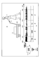
- the activity meter (sensor device) 4 is attached to the arm or leg of the wearer (measurement subject 2).
- the detection target 2 wearing the activity meter 4 pushes the carriage 122 and detects from the activity meter 4.
- the activity meter may be embedded in a part of a wearing item or clothing (clothing) such as a hat, glasses, or shoes worn by the human body.
- the basic contents of this embodiment are: (1) Obtain a detection raw signal obtained from an activity meter attached to a human body (or animal), (2) Extract the reference using the obtained detection raw signal, (3) signal processing from the detected raw signal based on the extracted reference; (4) Estimate the behavior (or state or request) of the human body (or animal) based on the signal processing results, (5) Analyzing the action history (for example, work / working) for each measurement target person (worker), (6) Perform processing in accordance with the flow of (1) to (6) to connect the analysis result to business improvement (improvement of work process) (may be omitted in some cases). Further, not limited to this process, the process of (7) providing an appropriate service may be performed using the estimation results obtained in (1) to (4). Furthermore, the system according to the present embodiment is not limited thereto, and may be arbitrarily utilized using the above estimation result.
- the present embodiment further fixes a sensor device to a predetermined object (other than a person or an animal), estimates a state related to the predetermined object based on a detection signal obtained from the sensor device, Service provision may be performed based on this.
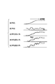
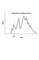
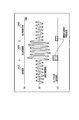
- FIG.1 (b) has shown the change of the measurement object person 2 for every elapsed time, and the change of the detection raw signal (acceleration waveform) acquired from the active mass meter 4 at the time of each action.
- the person to be measured 2 ⁇ Perform manual operation 20 from 9am to 9am, ⁇ After moving the carriage 22 between 9:01 and 9:03, ⁇ Until 24: 9, temporarily stop 24. ⁇ Walk from 9: 4 to 9: 6.
- the activity meter 4 obtains a unique detection signal (acceleration waveform) for each action.
- the behavior of the measurement subject 2 can be estimated by using the behavior estimation engine 14 and extracting the characteristics of these unique (original) detection raw signals (acceleration waveforms).
- the detection raw signal (acceleration waveform) acquired from the activity meter 4 is temporarily stored in the memory unit (output waveform data storage unit from the sensor) (corresponding to the processing of (1) above), and the memory unit (2) Reference extraction and (3) Signal processing, (4) Behavior estimation, (5) History analysis, (6) Work using the detection raw signal (acceleration waveform) read from (output waveform data storage unit) A series of processing until planning for improvement 10 is performed.
- the present invention is not limited to this, and the processing (2) to (6) may be performed in real time on the detected raw signal (acceleration waveform) in contrast to the processing (1) acquired from the activity meter 4 (1). . Furthermore, based on the behavior estimation result 16, the process (7) (providing appropriate services) may be performed.
- Direction is preset.
- the relationship between these axes and a predetermined reference is, for example, a measurement subject wearing an activity meter 4 as shown in FIG.
- the direction from the second arm 120 toward the middle finger is set as the Y axis.
- the action direction 100 (direction in which the measurement subject 2 exerts a force) when the measurement subject 2 pushes the carriage is matched with the Y-axis direction.
- the axis direction perpendicular to the back of the measurement subject's hand is set as the Z-axis direction
- the direction perpendicular to the Y-axis and the Z-axis (the direction from the little finger of the measurement subject 2 to the thumb) is set as the X-axis.
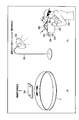
- magnetic field strength signals in the X-axis, Y-axis, and Z-axis directions are obtained from the triaxial geomagnetic sensor 74.
- a direction along the reference A (geomagnetic direction) 102 is defined as a y-axis (a direction from the south pole direction 114 toward the north pole direction 112).
- a direction from the west direction to the east direction is defined as the x-axis.
- the detection raw signals WX (t), WY (t), and WZ (t) are obtained from the triaxial acceleration sensor 72 (FIG. 17) built in the activity meter 4, respectively.
- the activity meter data (acceleration waveform) 12 shown in FIG. 1 corresponds to WZ (t) (or WY (t)).
- the detection raw signals WX (t), WY (t), and WZ (t) that are sequentially collected with the passage of time are sequentially stored in the memory unit (output waveform data storage unit) 82 in FIG.
- the detection raw signals WX (t), WY (t), and WZ (t) stored in the memory unit (output waveform data storage unit) 82 at a time are continuous actions of the measurement subject 2 for 2 to 3 hours. Data corresponding to can be used. In addition, the action data of the measurement subject 2 for one day may be stored at a time.
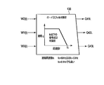
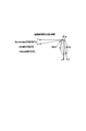
- FIG. 2 shows a method of extracting the reference B (gravity direction) 104 by using the signal components Q41L and Q42L subjected to the low-pass filter processing indicating the acceleration.
- the low-frequency component Q42L of the detection raw signal WY (t) acquired in the Y-axis direction the low-frequency component Q41L of the detection raw signal WZ (t) acquired in the Z-axis direction, and the gravitational acceleration component G facing the z-axis direction
- the gravitational acceleration component G facing the z-axis direction
- the angle ⁇ yz can be calculated by using any one of the above formulas (1), (2), and (3).
- the functions of the reference direction extraction 92 and the angle extraction 94 described in FIGS. 12 and 13 calculate the angle ⁇ by extracting the reference B (gravity) 104 from the detected raw signal using FIGS. 3 and 2. This corresponds to the function and the function of calculating the angle ⁇ by extracting the reference A (geomagnetic direction) 102 from the detected raw signal using FIG. 2 and FIG.
- the function of the detection signal generation (signal processing) 96 after the noise component reduction described in FIGS. 12 and 13 is based on the detection raw signals WX (t), WY (t), and WZ (t) from Equation (4) to This corresponds to the function of converting the detection signal “WY (t)
- ⁇ yz ⁇ s” or Wy (t) in a predetermined direction by performing signal processing using the equation (7).
- the vibration is mixed into the detected raw signals WX (t), WY (t), and WZ (t) as disturbance noise components.
- the frequency resulting from the vibration of the arm 120 of the measurement subject 2 is often 0.5 Hz or more.
- the signal components Q41L, Q42L, and Q43L after the low-pass filter processing 138 is performed on the detected raw signals WZ (t), WY (t), and WX (t) are extracted as described above. Disturbance noise component can be reduced.
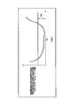
- the characteristic of the gain g with respect to the frequency f of this low-pass filter is the characteristic shown in FIG. 3, it is possible to extract only the signal component below the cutoff frequency fc.
- the value of the cut-off frequency fc when performing the low-pass filter processing 138 can be set to 60 Hz or 50 Hz from the above description, or may be set to 0.5 Hz.
- any filter processing may be employed in the present embodiment.
- band pass filter processing for extracting only specific frequency components may be performed.
- the arm and carriage 122 of the measurement subject 2 extracted from the gravity acceleration values are extracted.
- a method of converting the coordinate system of the measurement acceleration into a coordinate system capable of estimating the action of the measurement subject 2 will be described.
- FIG. 4 shows a coordinate conversion situation between the y-axis / z-axis and the Y-axis / Z-axis when the X-axis and the x-axis coincide.
- the conversion equation between the detection waveform Wy (t) / Wz (t) after the conversion process and the detection raw signal WY (t) / WZ (t) is
- the detection raw signals WX (t), WY (t), WZ (t) obtained from the triaxial acceleration sensor 72 (or the triaxial geomagnetic sensor 74) are used as the reference A (the geomagnetic direction).
- Converted detection signals Wx (t), Wy (t) estimated to be obtained in the directions of the y-axis parallel to 102 and the z-axis (and the x-axis orthogonal to them) parallel to the reference B (gravity) 104 ), Wz (t) can be calculated.
- a triaxial acceleration sensor 72 (or triaxial geomagnetic sensor 74) is used as the sensor, a plurality of sensors that change over time such as Wx (t), Wy (t), and Wz (t) from one or a plurality of sensors.
- the detected raw signal is collected. Then, for example, as a result of uneven distribution of noise components by signal processing across a plurality of detection raw signals using the characteristics of the obtained detection raw signals (extraction of predetermined unique information such as ⁇ yz included therein)
- the noise component of a predetermined detection signal for example, Wy (t) after signal processing Is effective.
- a specific signal component included in the detection raw signal is extracted by signal processing across the plurality of detection raw signals (for example, extraction of gravity acceleration value G using equation (1), etc.). May be.
- signal processing may be performed across a plurality of detection raw signals collected simultaneously from a plurality of different types of sensors such as the triaxial acceleration sensor 72 and the triaxial angular velocity sensor 212.
- predetermined unique information included in the detection raw signal means “the rotation direction 218 of the handle 214” or “the acceleration of the bus / truck, passenger car 210 / “Deceleration direction”, “Bus or truck, direction of change of traveling direction of passenger car 210”, and the like.
- identification of a specific sensor mounting direction (a direction of a predetermined coordinate axis installed in the specific sensor) and a specific signal component (for example, “acceleration / deceleration”, the acceleration of the detected acceleration at the start of acceleration / deceleration)
- a specific signal component for example, “acceleration / deceleration”, the acceleration of the detected acceleration at the start of acceleration / deceleration
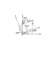
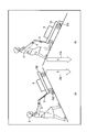
- the handling for the standard height measurement subject 140 and the lower height measurement subject 142 or the higher height measurement subject 144 will be described.
- the angle ⁇ yz when the measurement subject 142 whose height is lower than the standard presses the carriage 122 is ⁇ yz ⁇ compared with the angle ⁇ s when the measurement subject 140 of the standard height pushes the carriage 122.
- the angle ⁇ yz when the measurement subject 144 whose height is higher than the standard pushes the carriage 122 is ⁇ yz> ⁇ s.
- a feedback method (a kind of learning) related to a threshold used in processing of action estimation for a measurement subject 142 having a height lower than the standard height or a measurement subject 144 having a height higher than the standard height. Function).
- the measurement subject 144 whose height is higher than the standard pushes the carriage 122 (FIG. 7A)
- the value of the angle ⁇ yz formed by the action direction 100 and the direction in which the carriage 122 moves (y axis) increases.
- the force by which the person to be measured 144 presses the carriage 122 against the floor surface is increased.
- the dynamic frictional force and the static frictional force of the carriage 122 become large, and the carriage 122 becomes difficult to move.
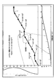
- FIG. 8 is based on the angle ⁇ s, and the error amount between the standard measurement acceleration after conversion with respect to the angle ⁇ yz when the measurement subject 2 pushes the carriage 122 and the measurement acceleration waveform (detected raw signal) or the standard measurement acceleration waveform (sample data). The relationship between the Euclidean distance compared to) is shown.
- the characteristic shown in FIG. 8 is a value sufficiently smaller than the determination threshold 150 when estimating the behavior of the measurement subject.
- the determination threshold 150 at the time of behavior estimation is automatically corrected (the determination value 150 is set to a larger value).
- FIG. 4 which is the basis for deriving the above equation (4) is a diagram in which the y-axis and the z-axis are rotated by ⁇ yz while the X-axis and the x-axis are matched (vertical rotation). The coordinate transformation of the three-dimensional transformation is shown.
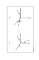
- FIG. 9A shows a diagram (horizontal rotation coordinate conversion... Rotation conversion) in which the z axis and the x axis are rotated by ⁇ zx while the Y axis and the y axis coincide with each other and converted to the Z axis and the X axis.
- FIG. 9B shows a diagram in which the x-axis and the y-axis are rotated by ⁇ xy while the Z-axis and the z-axis coincide with each other and converted into the X-axis and the Y-axis.
- ⁇ yz> ⁇ s” is used to perform signal processing to convert the detection signal into a Wy (t) detection signal with less noise components. Think about when you can. Then, in the above signal processing, the detection raw signal “WY (t)
- ⁇ yz ⁇ s
- WY (t) WY (t)
- ⁇ yz ⁇ s
- the angle between the Z-axis and the Zs-axis and the angle between the X-axis and the Xs-axis when the Y-axis and the Ys-axis coincide with each other are represented by d ⁇ zx.
- the angle between the X-axis and the Xs-axis and the angle between the Y-axis and the Ys-axis when the Z-axis and the Zs-axis coincide with each other are represented by d ⁇ xy.
- measured acceleration waveforms (detected raw signals) WX (t), WY (t), obtained from the activity meter 4 worn by the measurement subject 142 lower than the standard height or the measurement subject 144 higher than the standard height
- WZ (t) is converted into WXs (t), WYs (t), WZs (t) (standard measurement acceleration after conversion to the corresponding standard height), and based on the detection signal (standard measurement acceleration) after conversion
- FIG. As a result, there is an effect that the behavior estimation with respect to the measurement subjects 140 to 144 can be performed with high accuracy on a common scale regardless of the height difference of the measurement subjects 140 to 144.
- the method of using the rotation coordinate conversion between the coordinate axes shown in FIG. 4 has been described as a method of converting into a detection signal that reduces the influence of the height of the measurement subject 2 by signal processing.
- the present embodiment is not limited to this, and in the present embodiment, any other signal processing is possible as long as the signal processing uses the detection raw signals Wx (t), Wy (t), and Wz (t) obtained from the various sensors 72 and 74.
- a method may be used.
- the detection raw signals Wx (t), Wy (t), and Wz (t) may be regarded as three-dimensional vectors, and vector calculation processing (for example, vector synthesis processing) between the vector components may be performed.
- the present invention is not limited to this, signal processing across the detection raw signals obtained from a plurality of different sensors 72 and 74 is performed, and detection signal generation (signal processing) 96 (FIG. 12 or FIG. 13) after noise component reduction is performed. May be. That is, in the conversion between the detection signals using the equation (4) calculated using FIG. 4, for example, the conversion between the detection signals obtained only from the triaxial acceleration sensor 72 is performed.
- the present invention is not limited to this.
- signal processing in which detection signals obtained from the triaxial geomagnetic sensor 74 are also combined may be performed to reduce the noise component of the detection raw signal.
- the angle ⁇ yz of the arm 120 of the person 2 to be measured when the carriage 122 is pushed changes with time. Therefore, it is necessary to repeat the process of calculating the detection signal after rotation conversion (signal processing) many times.
- One or more of the detection raw signals WX (t), WY (t), and WZ (t) collected from the triaxial acceleration sensor 72 are referred to as “measurement acceleration waveform (detection raw signal)”.
- ⁇ yz ⁇ s, WY (t) collected from the triaxial acceleration sensor 72 obtained directly when the measurement subject 140 (FIG. 5 or FIG. 6) of the standard height pushes the carriage 122
- ⁇ yz ⁇ s, WZ (t)
- the standard acceleration (detected raw signal) is stored in the memory unit 82 (FIG. 12) and used as reference data (sample data) at the time of behavior estimation
- the standard stored in the memory unit 82 is used.
- the acceleration (detected raw signal) is referred to as “standard measurement acceleration waveform (sample data)”.
- the standard measurement acceleration waveform (sample data) may be sample data collected only once from the measurement subject 140 having a single standard height, or may be an average value of data collected multiple times or a plurality of standard heights. An average value of data obtained from the measurement subject 140 may be used.
- cycle the processing from “collection of detection raw signal ⁇ signal processing (rotation conversion of detection signal)” is described as “cycle”.
- cycle frequency The number of cycles repeated per second
- cycle period the time required for one cycle.
- the cycle period corresponds to the “resolution” (information collection speed) of the cycle process.
- the accumulation period of data of standard measurement acceleration after conversion necessary for statistical processing is referred to as “statistic processing accumulation period”.
- This behavior estimation unit period (a period for collecting statistical processing results) is referred to as a “behavior estimation determination period”.
- the cycle frequency in the system of the present embodiment (behavior estimation system 52), the higher the resolution of the cycle processing, and the easier the detection of the measurement subject 2's behavior change.
- the action (work) of the person to be measured 2 changes from manual work 20 to cart movement 22, stationary, walking 26 every minute or every two minutes.
- the behavior (work) of the measurement subject 2 may change more frequently.
- the cycle period in this embodiment is set to 10 seconds or less at the longest.
- the cycle period in this embodiment is preferably 0.5 seconds or less.
- the description will be continued by temporarily setting 20 Hz as an example of the cycle frequency.
- the value of the cut-off frequency fc when extracting a predetermined reference is set to 50 Hz or 60 Hz
- the value of the cut-off frequency fc has a certain degree of consistency with the aforementioned cycle frequency of 20 Hz.
- the cutoff frequency fc is set to a low value such as 0.5 Hz
- the low-pass filter processing 138 may be performed using the detection raw signal for a plurality of cycles.
- the system (signal processing system) of this embodiment detection from the triaxial acceleration sensor 72 and the triaxial geomagnetic sensor 74 (converted into a digital signal by the A / D converter 78 via the signal amplifier group 76).
- the raw signal is temporarily stored in the memory unit 82, and then read out in response to an instruction from the control unit 80 and processed. Therefore, the low-pass filter processing 138 using the detection raw signal for a plurality of cycles is facilitated.
- the present invention is not limited thereto, and signal processing in real time may be performed by properly using the processing of the memory unit 82.
- the statistical processing accumulation period described above will be described. For example, it is meaningless to perform statistical processing on data of only one cycle. In order to perform effective statistical processing, it is desirable to accumulate data of at least 4 cycles, preferably 10 cycles or more. For example, when the cycle frequency is 20 Hz (cycle period 50 mS), the accumulation period for statistical processing requires 0.5 seconds to accumulate data for 10 cycles.
- the behavior estimation determination period needs to be at least four times (preferably at least eight times) the statistical processing accumulation period. For the above reason, 4 seconds may be set as the action estimation determination period.
- the relationship between the periods is “behavior estimation judgment period” ⁇ “statistical processing accumulation period” ⁇ “cycle period”.
- A Dispersion between detection signals before and after rotation conversion (signal processing) and irregularity determination (A1) Z-axis direction (gravity component) or Y-axis direction (trolley movement direction) for each statistical processing accumulation period described above )
- A1 Z-axis direction (gravity component) or Y-axis direction (trolley movement direction) for each statistical processing accumulation period described above
- the measured acceleration waveform (detected raw signal) and the converted standard measured acceleration that is, the difference value between the measured acceleration waveform (detected raw signal) per cycle and the converted standard measured acceleration
- statistical processing is performed on the difference (the magnitude of motion) in the dispersion characteristics between the data within the statistical processing accumulation period. Then, it is determined whether the statistically processed variance value is within a predetermined threshold.
- the random value means the number of times the sign of the difference value changes within the statistical processing accumulation period.
- the difference value between the measured acceleration waveform (detected raw signal) in the k-th cycle and the standard measured acceleration after conversion is represented by ⁇ (k).
- D (k) ⁇ 1
- D (k) ⁇ 1
- D (k) 0.
- the total value of D (k) within the statistical processing accumulation period is defined as a random value.
- the sequence ⁇ D (1), D (2), D (3), D (4), D (5), D (6), D (7), D (8), D (9) ⁇ , ⁇ +1, +1, +1, -1, -1, +1, +1, +1, +1 ⁇ .
- the code change of “+ 1 ⁇ ⁇ 1” changes once, and the code change of “ ⁇ 1 ⁇ + 1” changes twice, so the random value is “2”.
- the frequency (similarity) that simultaneously satisfies the above (A1) and (A2) is 80% or more within the determination period of the behavior estimation, it is determined that they match.
- the cycle period is 50 ms
- the statistical processing accumulation period is 0.5 seconds
- the action estimation determination period is 4 seconds.
- the statistical processing accumulation period is sequentially set while shifting for each cycle period. Accordingly, the statistical processing accumulation period can be set 80 times (4000 ⁇ 50) during the behavior estimation determination period (4 seconds). Therefore, if 80% or more of the statistical processing results of 80 times (64 times or more) satisfy (A1) and (A2) at the same time, it is determined that the person to be measured 2 is 20 during movement of the carriage.
- (B) Determination of similarity between standard measurement acceleration after conversion and sample data (B1) Standard measurement after conversion in Z-axis direction (gravity component) or Y-axis direction (movement direction of carriage) for each statistical processing accumulation period Dispersion between acceleration and standard measurement acceleration waveform (sample data) (that is, the difference value between the standard measurement acceleration after conversion for each cycle and standard measurement acceleration waveform (sample data) is regarded as one data, and statistical processing is performed. Statistical processing is performed on the difference (the magnitude of movement) in the distribution characteristics between the data within the storage period. Then, it is determined whether or not the statistically processed variance value is within a predetermined threshold.
- the above expansion / contraction matching method refers to the degree of similarity between the sample data (standard measurement acceleration waveform) pattern and the detection signal (converted standard measurement acceleration) pattern, taking into account partial expansion and contraction on the time axis.
- the pattern matching method is a generic term for the pattern matching method to calculate.
- detected raw signals WX (t), WY (t), WZ (t) (at least one of these or a predetermined frequency component or a predetermined signal component)
- the value of (detected value) changes over time.
- the change speed with the passage of time varies depending on the measurement target person 2.
- the change speed of the detection raw signal used for estimating human or animal behavior or estimating the state of a predetermined object varies for each measurement target.
- the variation in the change rate of the detection raw signal is absorbed (to the expansion / contraction of the detection raw signal in the time passage direction). And has the effect of improving the estimation accuracy.
- FIG. 11 shows an application example to a warehouse management system called WMS (Warehouse Management System) as a usage scene of the present embodiment shown in FIG.
- WMS Warehouse Management System
- This WMS is broadly divided into a mechanism for solving two types of problems corresponding to “stock grasp” and “work support”.
- stock grasp grasp of the shelf life of inventory
- grasp of the storage position for each article in the warehouse grasp of the like can be mentioned.
- each image marker MK indicating the contents of the article is installed.
- the image marker MK a one-dimensional or two-dimensional code, or a mark (icon or the like) that can easily identify the contents of an article at a glance is described.
- the present invention is not limited to this, and each image marker MK may be a communication node with a built-in wireless communication function, or the image marker MK may have an arrangement information (position information) detection function using a beacon. .
- each rack (shelf) RK is selected / extracted (picked) by a worker (personal worker) PW (or measurement subject 2) and placed in a cart ( ⁇ ) CRT (or a large object). In the case of the transported object 8, it is put on the carriage 122).
- this worker PW wears the activity meter 4, and collects the detection raw signal from the activity meter 4 (1).
- the collected raw detection signals are temporarily stored in a memory unit (output waveform data storage unit from the sensor). Thereafter, the detection raw signal is read, and the processes (2) to (6) described above are performed.
- the result is used to improve the work of each worker PW (or the person 2 to be measured 2) (improvement of work action process and procedure).
- a service such as the next action instruction is provided to the worker PW (or the person 2 to be measured) using the glasses-type wearable terminal (driving device) 1100 (see the detailed description using FIG. 38 and subsequent figures) ( 7) may be performed.
- the present embodiment is not limited to this, and the present embodiment may be applied to, for example, the social infrastructure market, the personal market, the healthcare market, the production / management market (design / manufacturing / inspection site), and the like.
- it may be used as a social infrastructure market, transportation environment or construction environment such as bridges and buildings, supply market of public consumer goods such as electricity, water and gas, financial industry market such as banking and securities / non-life insurance.
- public consumer goods such as electricity, water and gas
- financial industry market such as banking and securities / non-life insurance.
- you may use for a business use and application for each home.
- health care market it may be used at medical sites or nursing homes.
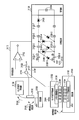
- the hardware configuration of the signal processing system in the present embodiment illustrated in FIG. 12 includes an activity meter 4, a sensor device 6, an edge device 42, and a server 40.
- the sensor device 6 is fixed to a predetermined object other than a person (for example, a carriage 122).
- a wired or wireless communication line is configured between the activity meter 4 and the edge device 42, between the sensor device 6 and the edge device 42, and between the edge device 42 and the server 40. Communication is possible.
- the edge device 42 and the server 40 cooperate to perform estimation result processing and service provision control, which will be described later.
- processing results contents of the transmission information 30
- the signal processing unit 60 inside the sensor device 6 are also collected.
- the functional configuration of the signal processing system shown in FIG. 12 includes an action estimation system 52, a service control unit 58, a position detection signal generation unit 46, and a control unit 48 thereof.
- the behavior estimation system 52 includes the activity meter 4, the sensor device 6, and a part of the edge device 42.
- the structure of the activity meter 4 is mainly described, but the hardware configuration 62 and the functional configuration 64 of the sensor device 6 basically match the structure of the activity meter 4.
- the activity meter 4 (and sensor device 6) includes a fixed member 50 and a signal detector 60.
- the fixing member 50 has a function of fixing the signal detection unit 60 to a part of the body of the measurement subject 2 when the measurement subject 2 is worn.
- the specific structure of the fixing member 50 has a wristband structure as shown in FIG. 1A and can be directly attached to the arm or foot of the person 2 to be measured.
- a structure that is attached to a human body using an adhesive layer, a part of a wearing part such as a hat, glasses, or shoes or a part of clothes (clothing) may be used.
- a part of a string used for packaging of the adhesive layer or the transported object 8 may be used as a structure of the fixing member 50 when the sensor device 6 is fixed to the transported object 8.
- the entire signal detector 60 is built in the activity meter 4 (or in the sensor device 6).
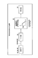
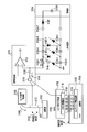
- the hardware configuration 62 of the signal detection unit 60 includes a power generation unit (environmental vibration type or photoelectric conversion type) 68 and a power storage unit (battery) 66, a triaxial acceleration sensor 72, a triaxial geomagnetic sensor 74, a signal amplifier group 76, A A / D converter (Analog to Digital Converter) 78, a control unit 80, a memory unit 82, and a communication control unit 84 are included.
- the power generation unit 68 As the form of the power generation unit 68, an environmental electric type described later may be used, or a photoelectric conversion type such as a solar cell may be used.
- the electric power generated by the power generation unit 68 is stored in the power storage unit 66. Then, each circuit of the signal detection unit 60 operates using the electric power stored in the power storage unit 66.
- the triaxial acceleration sensor 72 obtains acceleration signal waveforms (WX (t), WY (t), WZ (t)) in three axial directions (X-axis, Y-axis, and Z-axis directions) orthogonal to each other.
- the direction of geomagnetism can be detected using the triaxial geomagnetic sensor 74.
- the three-axis directions defined in the geomagnetic sensor 74 are also completely coincident with the three-axis directions (the X-axis, Y-axis, and Z-axis directions) of the three-axis acceleration sensor 72 described above. Yes. That is, in the signal detector 60 of the activity meter 4 and the signal detector 60 of the sensor device 6, three orthogonal directions (X axis, Y axis, and Z axis) are set in advance.
- a three-axis sensor for convenience of explanation, explanation will be made using an example of a three-axis sensor.
- the present invention is not limited to this.
- a 1-axis sensor or a 2-axis sensor may be used, or a further multi-axis sensor (for example, a 3-axis acceleration sensor function and a multi-axis angular velocity sensor function are built in the same sensor) may be used.
- a further multi-axis sensor for example, a 3-axis acceleration sensor function and a multi-axis angular velocity sensor function are built in the same sensor
- the detected raw signals (WX (t), WY (t), WZ (t)) in the three-axis directions obtained from the three-axis acceleration sensor 72 and the three-axis ground axis sensor 74 are individually amplified by the signal amplifier group 76. After that, it is converted into a digital signal by an A / D converter (Analog-to-Digital Converter) 78 and stored once in the memory unit 82.
- the signal detection unit 60 includes a control unit 80 and performs signal processing using the detection raw signals (WX (t), WY (t), WZ (t)) stored in the memory unit 82. . Further, the signal processing result is transmitted as transmission information 30 to the edge device 42 via the communication control unit 84.
- the detection raw signal is extracted from the triaxial acceleration sensor 72 and the triaxial geomagnetic sensor 74, and is converted into a digital signal by the A / D converter 78 through the signal amplifier group 76.
- the reference direction extraction 92 and the angle extraction 94 based on the result obtained by the detection raw signal generation 90 and the detection signal generation (signal processing) 96 after noise component reduction are performed by the control unit 80 while using the memory unit 82.
- the reference direction extraction 92 means a function of extracting a predetermined reference (direction) using the result of the detection raw signal generation 90.
- the gravitational direction for example, the z-axis direction
- the direction of geomagnetism for example, the y-axis direction
- a predetermined reference (the direction of the z axis or the y axis corresponding to the direction) and the coordinate axes (X axis and Y axis) set in advance in the activity meter 4 or the sensor device 6 are used.
- the process of calculating the angle ⁇ between the axis and the Z axis corresponds to the angle extraction 94 described above.
- the detection signal generation (signal processing) 96 after noise component reduction is a signal processing of the detection raw signals (WX (t), WY (t), WZ (t)) using the result of the angle extraction 94.
- it means a function of generating detection signals (Wx (t), Wy (t), Wz (t)) after noise component reduction.
- At least one of the detection signals (Wx (t), Wy (t), Wz (t)) obtained as a result is a detection raw signal (WX (t), WY (t), WZ (t)).
- the noise component is further reduced.
- the result is transmitted from the activity meter 4 to the edge device 42 via the communication control unit 84.
- the transmission information 30 transmitted at this time includes extraction angle information 32 and detection signal information 34 after noise component reduction.
- the system of this embodiment shown in FIG. 12 has a communication control unit 84 built in both the activity meter 4 and the sensor device 6, and each has a wireless communication function. Using this wireless communication function, the user's position may be detected by a method similar to GPS (Global Positioning System).
- GPS Global Positioning System
- the position detection signal transmitters 46 controlled by the position detection signal generation controller 48 of the edge device 42 are distributed in different locations from (A) to (D). From each of the points (A) to (D), transmission time information is continuously transmitted wirelessly. Further, a time difference received by the communication control unit 84 of time information transmitted from each of the points (A) to (D) is detected, and the active meter 4 (or sensor device 6) is arranged in real time using trigonometry. The location can be detected.
- the behavior estimation engine 56 of the behavior estimation unit 54 owned by the edge device 42 performs behavior estimation (or state estimation or request estimation of the measurement subject 2) based on the transmission information 30 transmitted from the sensor devices 4 and 6. Based on the estimation result, the service control unit 58 proposes service provision and business improvement 10.
- the content of the service instruction 11 is returned from the server 40.
- the driving device 44 is operated from the edge device 42 using wireless communication, and the service is provided to the measurement subject 2 or other users.
- the drive device 44 incorporates an electric motor, a light emitting element, a display element, a speaker, and the like, and performs driving, light emission, display, audio output, and the like of the electric motor according to an operation from the edge device 42.
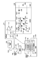
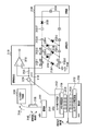
- FIG. 13 shows another embodiment system relating to the signal processing system shown in FIG.
- the embodiment system (signal processing system) of FIG. 13 only the detection raw signal generation 90 and the position detection 98 are performed in the activity meter 4 (or in the sensor device 6) in the functional configuration 64 that the position detection unit 60 assumes. Executed.
- the detected position information 38 and the detected raw signal information 36 are transmitted as the activity information 4 or sensor device. 6 to the edge device 42.
- the edge controller 42 is particularly specified with the communication control unit 86, the control unit 81, and the memory unit 83 included in a part of the hardware configuration 62 of the signal detection unit 60.
- the communication device 86, the controller 81, and the memory unit 83 exist in the edge device 42 even in the signal processing system form shown in FIG. 12.
- the detected position information 38 and the detected raw signal information 36 transmitted from the activity meter 4 (or the sensor device 6) are transmitted via the communication control unit 86.
- the control unit 81 of the edge device 42 performs signal processing using the detection raw signals (WX (t), WY (t), WZ (t)) stored in the memory unit 83.
- the detection signals (Wx (t), Wy (t), Wz (t)) after noise component reduction obtained as a result of this signal processing are also stored in the memory unit 83.
- the signal processing is performed on the detection raw signals (WX (t), WY (t), WZ (t)) collected from the triaxial acceleration sensor 72 and the triaxial geomagnetic sensor 74 by the edge device 42.
- the functions of the meter 4 and the sensor device 6 can be simplified. As a result, there is an effect that the entire signal processing system as well as the active mass meter 4 and the sensor device 6 can be made inexpensive.
- the behavior estimation engine 56 built in the behavior estimation unit 54 of the edge device 42 detects the detection signal (Wx (t), Wy (t), Wz (t)) after the noise component reduction stored in the memory unit 83. Is used to perform the action estimation process or state estimation process of the measurement target person 2 and the request estimation process (of the measurement target person 2 or other users).
- the hardware configuration 63 for executing the processing of the behavior estimation unit 54 at this time is the content of the hardware configuration 62 belonging to the signal detection unit 60 installed in the edge device 42 (communication control unit 86 and control unit 81, memory unit 83). Is also used.
- the behavior estimation result 16 performed by the behavior estimation engine 56 of the behavior estimation unit 54 owned by the edge device is transmitted to the server 40.
- the server 40 examines the service provision contents using the result. Thereafter, the service instruction 11 is issued from the server 40 to the edge device 42.
- the direction from the arm 120 of the measurement subject 2 wearing the activity meter 4 toward the middle finger is set as the Y axis.
- the action direction 100 (the direction in which the measurement subject 2 exerts a force) when the measurement subject 2 pushes the carriage is matched with the Y-axis direction.
- the direction perpendicular to the back of the measurement subject's hand is set as the Z-axis direction
- the direction perpendicular to the Y-axis and the Z-axis (the direction from the little finger of the measurement target 2 toward the thumb) is set as the X-axis.
- acceleration waveforms detected raw signals WX (t), WY (t), WZ (t)
- the Y-axis direction, and the Z-axis direction are obtained from the triaxial acceleration sensor 72. .
- the magnetic field intensity signals in the X-axis, Y-axis, and Z-axis directions may be described from the triaxial geomagnetic sensor 74.
- WX * (t), WY * (t), or WZ * (t) may be described).
- a direction along the reference A (geomagnetic direction) 102 is defined as a y-axis (a direction from the south pole direction 114 toward the north pole direction 112).
- the direction from the west direction to the east direction is defined as the x-axis.
- the waveforms of Wx (t) and Wy (t) are not directly detected as detection raw signals.
- the direction in which the measurement subject 2 pushes the carriage 122 (the action direction 100 of the Y axis) has an inclination of ⁇ yz with respect to the plane 118 perpendicular to gravity.
- the inclination angle between the z-axis and the Z-axis is also ⁇ yz.
- the time change of the virtual acceleration waveform Wy (t) to be obtained in the y-axis direction is shown on the right side of FIG.
- the Wy (t) waveform increases with time as the carriage 122 starts moving. To do.
- the time change of the virtual acceleration waveform to be obtained in the gravity direction (z-axis direction) at this time is represented by Wz (t). Since a constant gravitational acceleration always acts on the activity meter 4, a DC component corresponding to the gravitational acceleration G is always added to Wz (t).
- Neither the Wy (t) waveform nor the Wy (t) waveform shown on the right side of FIG. 15 can be directly collected as a detection raw signal from the triaxial acceleration sensor 72 (or triaxial geomagnetic sensor 74). However, if the angle ⁇ yz is used, the detection raw signals WZ (t) and WY (t) that can be directly collected by the triaxial acceleration sensor 72 (or triaxial geomagnetic sensor 74) are converted into Wz (t) and Wy (t). It can be calculated.
- reference is made using detection raw signals WX (t), WY (t), and WZ (t) obtained from various sensors of the sensor device (activity meter) 4 and the sensor device 6.
- a (geomagnetic direction) 102 and reference B (gravity direction) 104 are extracted.
- FIG. 16 shows an application example for FIG.
- signal processing using the detection raw signal from the activity meter 4 attached to the arm 120 of the measurement subject 2 / behavior estimation of the measurement subject 2 is performed, and the work improvement is performed through the behavior history analysis of the measurement subject 2. (Work process improvement) and provide necessary services.
- the behavior estimation of the measurement subject 2 is not limited thereto, and for example, the sensor device 6 is fixed to a part of a predetermined object such as the carriage 122 (by pasting or the like), and the signal from the detected raw signal alone collected from the sensor device 6 Processing / Behavior estimation ⁇ Behavior history / Business improvement and service provision may be performed.
- the detection raw signal from the activity meter 4 and the detection raw signal from the sensor device 6 may be combined. Combining both increases the estimation of the behavior of the measurement subject 2 and produces an effect that enables more appropriate business improvement planning and service provision.
- the edge device 42 can operate the drive device 44 to provide a service (to the measurement subject 2 or other users).
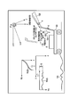
- an electric motor (drive device) 124 corresponding to a kind of the drive device 44 and a light emitting element or speaker (drive device) 126 are provided.
- the electric motor 124 moves based on the service instruction 11 from the server 40 determined that “the measurement subject 2 is moving on the carriage 20”. Light emission from the light emitting element or audio output from the speaker is performed. Since the electric motor 124 automatically starts during the movement of the trolley 2 of the measurement subject 2, an effect of reducing the burden on the movement of the trolley for the measurement subject 2 is produced. In addition, “warning” to a third party accompanying the movement of the carriage can be automatically performed by the light emission of the light emitting element or the sound output from the speaker. As a result, there is also an effect that enables the carriage to move safely (preventing inadvertent contact with a third party).
- the weak signals obtained from the various sensors 72 and 74 are amplified in the signal amplification group 76 inside the signal detection unit 60, and converted into digital signals through the A / D converter 78.
- a method for generating a signal component in a predetermined direction from the detected raw signals WZ (t), WY (t), WX (t) from the various sensors 72 and 74 using the angle ⁇ extracted by the above method will be described below. .
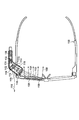
- FIG. 17 shows the change over time of the detection signal obtained directly or indirectly when the subject 2 pushes the stationary carriage 122 and the carriage 122 starts to move.
- the coordinate axes are the same as in FIG. 16 (when the X axis and the x axis coincide).
- the acceleration waveform Wy (t) in the movement direction (y-axis direction) of the carriage increases with time as shown in FIG.
- the acceleration waveform Wz (t) in the gravitational direction (z-axis direction) is added to the gravitational acceleration component G (DC component) that always exists, and an acceleration change corresponding to the uneven shape of the floor 128 appears. (FIG. 17B).
- the Y-axis direction set in advance in the activity meter 4 is inclined by the angle ⁇ yz with respect to the plane 118 perpendicular to gravity. Therefore, a noise component of Wz (t) (corresponding to the uneven shape of the floor surface 128) is mixed into the detection raw signal WY (t) according to the angle ⁇ yz.
- the ⁇ yz when the measurement subject 2 having a standard height pushes the carriage 122 is represented by ⁇ s.
- some signal processing is performed on the detection raw signal shown in FIG. 17C or 17E to reduce the influence of the height of the person 2 to be measured.
- the accuracy of determining the behavior estimation (or situation estimation) is improved. Occurs.
- the detection raw signal shown in FIG. 17C or FIG. 17E is converted into a detection signal “WY (t)
- the behavior estimation is performed by matching the waveform (correct waveform) that is the basis of the behavior estimation with the actual waveform.
- the waveform corrected waveform
- DP matching matching method based on dynamic programming
- FIG. 18A An example of a standard measurement acceleration waveform (sample data) measured in advance is shown in FIG.
- the acceleration in the movement direction (y-axis direction) of the trolley 122 increases from “0” with the passage of time.
- the detected acceleration decreases (FIG. 18A).
- the horizontal axis memory in FIG. 18 represents a cycle period (for example, 50 mS). Values for convenience of the standard measurement acceleration waveform (sample data) collected for each cycle period are clearly shown in each graph of FIG.
- FIG. 18B shows the detection raw signal WY (t) in the Y-axis direction when the action speed (work speed) when the measurement subject 2 this time starts to push the carriage 122 is slower than the “standard speed”.
- the low-frequency component (DC component) of Q42L caused by gravity is always superimposed on the detection raw signal WY (t) in the Y-axis direction.
- the measurement subject 2 compared with the standard measurement acceleration waveform (sample data) (FIG. 18A), the measurement subject 2 slowly pushed the carriage 122 this time. Therefore, the amount of acceleration change in FIG. 18B is smaller in FIG. 18B than the standard measurement acceleration waveform (sample data).
- FIG. 18C shows the characteristic after the amplitude value is normalized so that the resultant amplitude value matches that shown in FIG.
- the maximum signal amplitude matches the standard measurement acceleration waveform (sample data) of FIG. 18 (a). However, since the measurement subject 2 slowly pushes the carriage 122, the degree of signal change in the time axis direction is small (slow).
- the expansion / contraction matching method employed in the system of the present embodiment automatically corrects the difference in expansion / contraction in the time axis direction between FIG. 18 (a) and FIG. 18 (c).
- the degree of coincidence can be calculated. Therefore, pattern matching can be performed while correcting the difference in the action speed of the measurement subject 2 or the difference in the processing speed corresponding to the fixed object obtained by the sensor device 6, so that it is accurate regardless of variations in the action speed (processing speed). There is an effect that pattern matching determination can be performed.
- the waveform of FIG. 18C is transcribed in the horizontal axis direction of FIG. 19, and the waveform of FIG. 18A is transcribed in the vertical axis direction of FIG.
- the pattern amplitude in the horizontal axis direction matches the pattern amplitude in the vertical axis direction.
- the connection (arrow) between intersections having similar amplitude values is regarded as the optimum route, and the optimum route is sequentially searched. To do.
- This optimum route search is a process for absorbing variation in action speed (processing speed).
- the “enlarged area” shown in FIG. 19 is enlarged and shown in FIG.
- the amplitude change in the horizontal axis direction changes from “7” to “11” when the elapsed time advances by the cycle period, whereas the amplitude in the vertical axis direction changes from “8” to “13”.
- the value of the square of the deviation from the sample data after passing through the path (1) is calculated.
- the amplitude value in the vertical axis direction after passing through the path (1) remains “8” and does not change.
- the amplitude value in the horizontal axis direction changes from “7” to “11”.
- the route with the smallest square value of the deviation amount after passing the route is automatically selected. Therefore, in the example shown in FIG. 20, the route (2) having “4” having the smallest square value of the deviation amount is automatically selected. As a result of automatically selecting the optimum route in this way, it is possible to match patterns whose expansion and contraction in the time axis direction changes as in the relationship between FIGS. 18A and 18C.
- sample data When there are multiple candidates for behavior estimation of the person to be measured 2 (multiple types of standard measurement acceleration waveforms (sample data) are prepared), the standard measurement after conversion for each different standard measurement acceleration waveform (sample data) The Euclidean distance between the acceleration and the acceleration is calculated, and it is determined that the behavior of the measurement subject 2 is similar to the behavior estimation candidate with the smallest Euclidean distance.
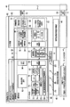
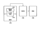
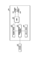
- FIG. 21 shows another embodiment in which the behavior estimation system 52 described above with reference to FIGS. 12 and 13 is realized with another hardware configuration.
- the behavior estimation system 52 includes a signal detection unit 60 and a behavior estimation unit 54.
- a memory unit (output waveform data storage unit) 82, an output waveform data / acceleration extraction unit 160, an angle extraction unit 164, a coordinate conversion unit 166, a filter unit 162, and a control unit (control management unit) ) 80 is included in the signal detection unit 60.
- the behavior estimation unit 54 includes a storage unit 170 for standard measurement target person data (sample data to be a target for matching comparison), a feedback data data storage unit 176, a feedback data processing unit 178, a threshold value change determination unit 182, The threshold value changing unit 184, the operation determining unit 172, the operation determining threshold storage unit 174, and a part of the control unit (control management unit) 80 are included.
- the memory unit (output waveform data storage unit) 82 stores data (detected raw signal) measured from the activity amount form 4.
- the memory unit (output waveform data storage unit) 82 corresponds to the memory unit 82 of FIG. 12 or FIG.
- the output waveform data / acceleration extraction unit 160 performs the function of the detection raw signal generation 90 of FIG. 12 or FIG.
- the specific hardware structure related to the output waveform data / acceleration extraction unit 160 corresponds to the triaxial acceleration sensor 72, the signal amplifier group 76, and the A / D converter 78 shown in FIG.
- the function of the filter unit 162 coincides with the function of the low-pass filter process 138 described with reference to FIG. That is, the filter unit 162 extracts the gravitational acceleration components Q41L, Q42L, and Q43L from the acceleration value output from the output waveform data / acceleration extraction unit 160.
- the low-pass filter characteristics of the prior art may be used, but not limited thereto, for example, a filtering method for obtaining an average value may be used. 21.
- the function of combining the angle extraction unit 164 and the filter unit 162 in FIG. 21 corresponds to the reference direction extraction 92 and the angle extraction 94 in FIG. That is, the angle extraction unit 164 calculates the angle ⁇ yz (see FIG.
- this angle extraction uses the gravitational component and the trigonometric function included in the acceleration value measured by the wristband type activity meter (sensor device) 4 attached to the arm 120 of the measurement subject, to determine the angle ⁇ yz. Perform the calculation.
- the coordinate conversion unit 166 has a function of detection signal generation (signal processing) 96 after noise component reduction in FIG. 12 or FIG. That is, the standard measurement after conversion using the equation (5) or (7) from the measured acceleration waveform (detected raw signal) WX (t), WY (t), WZ (t) acquired from the triaxial acceleration sensor 72 Rotational conversion (signal processing) into acceleration is performed here. At this time, the angle d ⁇ yz calculated from the angle extraction unit 164 using the gravity value is used.
- the standard measurement acceleration waveform (sample data) is stored in the storage unit 170 of the standard measurement target person data (sample data to be subjected to matching comparison).
- the next feedback data storage unit 176 stores data output by a feedback data processing unit described later.
- the error characteristic (or standard measurement acceleration waveform (sample data) between the standard measurement acceleration after conversion with respect to the angle ⁇ ( ⁇ yz) of the arm 120 of the measurement subject 2 and the measurement acceleration waveform (detected raw signal).
- the Euclidean distance characteristic was explained. This characteristic is stored in the feedback data storage unit 176.
- the operation determination unit 172 determines whether or not the action of the measurement subject 2 at the measurement target time has made the carriage move 20.
- the characteristics shown in FIG. 8 are used for this determination, and information on the determination threshold 150 when estimating the behavior of the measurement subject is used as the determination criterion.
- the information of the determination threshold value 150 at the time of estimating the behavior of the measurement subject is stored in the action determination threshold value storage unit 174.
- the error amount between the standard measurement acceleration after conversion with respect to the angle ⁇ yz of the arm 120 of the measurement subject 2 and the measurement acceleration waveform (detected raw signal) or the standard measurement acceleration waveform (sample data) and The compared Euclidean distance is appropriately calculated in real time for each cycle. Then, the threshold change determination unit 182 monitors in real time (for each cycle) whether or not the error amount or the Euclidean distance has exceeded the determination threshold 150 when the measurement subject's behavior is estimated. If the error amount or the Euclidean distance exceeds the determination threshold 150, information is transmitted to the threshold change determination unit 182 to change the determination threshold 150.
- the threshold value changing unit 184 performs change control of the determination threshold value 150 when estimating the behavior of the measurement subject based on the transmission information from the threshold value change determining unit 182.
- the method of rotation conversion explained in detail.
- the data stored in the memory unit (output waveform data storage unit) 82 is read out from the date of collecting the behavior data of the measurement subject 2 (at a later date), and the processing until the behavior estimation of the measurement subject 2 or ( A series of processes leading to the work improvement (work process improvement) in 6) may be performed together (batch processing).
- control unit 80 reads the detection raw signals WX (t), WY (t), and WZ (t) from the memory unit (output waveform data storage unit) 82, and the angle extraction unit 164. Forward to.
- the angle extraction unit 164 incorporates the function of the low-pass filter processing 138 described in FIG. 3, and calculates the values of Q41L, Q42L, and Q43L. Next, ⁇ yz and the like are calculated using equations (1) to (3) obtained from FIG. 2, and then d ⁇ yz and the like are calculated.
- the detection raw signals WX (t), WY (t), WZ are obtained by using the equation (5) obtained from FIG. 4 or the equation (7) obtained from FIG. 4, FIG. 9, and FIG. (T) is rotationally converted (signal processing), and standard measurement accelerations WXs (t), WYs (t), and WZs (t) after conversion are calculated.
- the method (A) to (C) (or a combination thereof) has already been described as a method for estimating the behavior of the measurement subject 2.
- (A) dispersion between detection signals before and after rotation conversion (signal processing) and irregularity determination are used for behavior estimation will be described.
- the feedback data processing unit 178 extracts the relationship between the error amounts between WZ (t) and the standard measurement accelerations WXs (t), WYs (t), and WZs (t) after rotational coordinate conversion. The extraction result is recorded in the feedback data storage unit 176.
- the data to be recorded in the feedback data storage unit 176 is the data of the measurement subject 2 measured the previous day for two or three hours of continuous data or one day of data at a time. Can be recorded together.
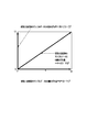
- the feedback data processing unit 178 statistically analyzes the data recorded in the feedback data storage unit 176, and the characteristics shown in FIG. Create a graph.
- the determination threshold value 150 at the time of the measurement target person behavior estimation is a constant value regardless of the angle ⁇ .
- the present invention is not limited to this, and the determination threshold 150 may be reset as appropriate according to the angle ⁇ .
- the threshold value change unit 184 sets the changed threshold value. Then, the changed threshold value corresponding to the reset angle ⁇ is appropriately stored in the action determination threshold value storage unit 174.
- the threshold value change determination unit 182 determines whether or not the threshold value change unit 184 needs to reset the threshold value. When the threshold needs to be reset, the information is transmitted from the threshold change determination unit 182 to the threshold change unit 184.
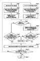
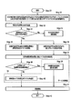
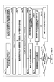
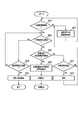
- FIG. 21 Another embodiment relating to the processing flow performed by the behavior estimation system 52 shown in FIG. 21 will be described with reference to FIGS. 22A to 22C.
- Step A1 the measurement object 140 of standard height measures acceleration waveform data obtained by moving the carriage 122, and the standard measurement object data (sample to be subjected to matching comparison). Data) is stored as a standard measurement acceleration waveform (sample data).
- Step A2 the output waveform data / acceleration extraction unit 160 acquires a detection raw signal (measurement acceleration waveform (detection raw signal)) from the measurement subject 2.
- Step B1 the filter unit 162 extracts the decomposition component of gravity acceleration (G41L and G42L). (See FIG. 3).
- Step B2 the angle extraction unit 164 calculates the tilt angle ⁇ ( ⁇ yz) of the arm 120 of the measurement subject 2 from the acquired Q41L and Q42L.
- formula (1), formula (2), or formula (3) obtained using FIG. 2 is used.
- setting 1 method of calculating ⁇ ( ⁇ yz) using equation (1)”
- setting 2 ⁇ ( ⁇ yz) using equation (2)
- setting 3 a method of calculating ⁇ ( ⁇ yz) using equation (3)” may be used.
- the present invention is not limited to this, and “setting 4: a method of using an average value between ⁇ ( ⁇ yz) values obtained by equations (1) and (2)” may be used. Furthermore, “Setting 5: Method of using the average of all values of ⁇ ( ⁇ yz) obtained by the equations (1), (2), and (3)” may be used.
- Step B3 the coordinate conversion unit 166 performs rotation conversion (signal processing) from the measured acceleration waveform (detected raw signal) WX (t), WY (t), WZ (t) to the converted standard measured acceleration.
- the above-described equation (5) or (7) is used for this rotation conversion (signal processing).
- Step A2 to Step B3 in FIG. 22A there is a relationship of “behavior estimation determination period” ⁇ “statistical processing accumulation period” ⁇ “cycle period”.
- one processing flow from Step A2 to Step B3 in FIG. 22A means one cycle of processing. Therefore, in order to perform the behavior estimation of the measurement subject 2 by the behavior estimation system 52, it is necessary to repeat the cycle at least the number of times corresponding to the “behavior estimation determination period” at least (for example, the “behavior estimation determination period”).
- “is 4 seconds and“ cycle period ” is 50 ms, it is necessary to repeat the processing flow from Step A2 to Step B3 at least 80 times at first).
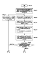
- Step B5 it is determined whether or not the above cycle has been repeated a predetermined number of times. If the predetermined number of times has not been reached, the output waveform data / acceleration extraction unit 160 advances (increments) one cycle and starts the next processing flow (cycle) from Step A2 to Step B3 (Step B10). On the other hand, if the behavior estimation process can be executed after the cycle has already been repeated a predetermined number of times, the process proceeds to Step B4.
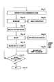
- the error between the measured acceleration waveform (detected raw signal) and the converted standard measured acceleration is the threshold condition.
- the operation determination unit 172 determines whether or not the user is satisfied.
- the dispersion and irregularity determination between detection signals before and after the above-described (A) rotation transformation (signal processing) (B) Determination of similarity between standard measurement acceleration after conversion and sample data (C) One or a combination of expansion / contraction matching determination between standard measurement acceleration after conversion and sample data may be performed.
- Step B7 If the threshold condition is not satisfied as the determination result of the above behavior estimation, it is determined that the measurement target person 2 has not moved the carriage 122 at the target time from the operation determination unit 172 (Step B7).
- Step B8 determines and outputs that the carriage is moving at the target time.
- the edge device 42 and the server 40 cooperate with each other as needed to improve the service based on the service provision and the measurement target person 2 action history. 10 proposals are made (FIGS. 1, 11 to 13).
- Step A2 The processing from Step A2 to Step B7 / B8 is repeated until the behavior estimation processing or service provision processing is completed. That is, in Step B9, it is determined whether or not all corresponding sections of the measurement data have been processed.
- Step E the series of processes is terminated (Step E).
- the process returns to Step A2 via Step B10.
- the determination threshold 150 at the time of estimating the behavior of the measurement subject as described with reference to FIG. 8 is appropriately changed (FIG. 22C).
- the feedback data processing unit 178 the measurement acceleration waveform (detected raw signal) with respect to the angle ⁇ ( ⁇ yz) of the arm 120 of the measurement subject 2 shown in FIG. A characteristic of an error amount with respect to acceleration (or a Euclidean distance calculated by comparison with a standard measurement acceleration waveform (sample data)) is determined. The result is recorded in the feedback data storage unit 176 (Step C1).
- the feedback data processing unit 178 reads the above characteristic data from the feedback data storage unit 176, performs statistical processing for each angle ⁇ ( ⁇ yz), and based on the result, the determination value 150 at the time of the action estimation unit for the measurement subject. A correction value of (matching threshold) is calculated. The correction value calculated there is stored in the feedback data storage unit 176 (Step C2).
- Step C3 The result is read from the feedback data storage unit 176, and the threshold value change determination unit 182 determines whether or not the angle error for each angle ⁇ ( ⁇ yz) exceeds a set value (for example, 15%) (Step C3). Here, if it does not exceed, the process after Step B4 is continued without performing a specific process.
- Step C3 determination result If the value exceeds the set value (Step C3 determination result), the threshold value is changed by changing the correction of the threshold value used for matching determination according to the extracted angle ⁇ ( ⁇ yz). This is performed by the unit 184 (Step C4).
- FIGS. 22A to 22C are examples of behavior estimation when the measurement subject 2 moves the carriage 20.
- the present embodiment system (behavior estimation system 52) is not limited to the cart 20 of the person to be measured 2 but can be applied to behaviour estimation for all other actions.
- the sensor device 6 is not limited to the specific measurement subject 2 and is obtained from the sensor device 6 fixed to a predetermined object (FIG. 25A) such as a part of the carriage 122 or the transported object 8 as shown in FIG. You may perform state estimation (estimation with respect to the state of a predetermined object) using a detection signal.
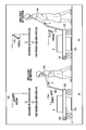
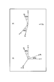
- the method of taking the angle ⁇ yz in FIGS. 2 and 15 is based on the coordinate axes (Y axis and Z axis) preset in the wristband type activity meter (sensor device) 4 as a reference line. Then, the angle ⁇ yz is set in the counterclockwise direction with respect to the rotation angle from the reference line (Y axis and Z axis).
- the present invention is not limited to this, and the angle ⁇ yz ′ may be set in the clockwise direction as shown in FIGS. 23 and 24. Similarly, the angle ⁇ yz ′ may be set in the counterclockwise direction by taking the z-axis or y-axis along the gravity direction or the floor surface direction as a reference line.
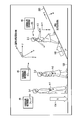
- FIG. 25A shows an example of a state estimation method when the measurement subject 2 transports the transported object 8 by directly holding it in the hand without using the carriage 122.
- the coordinate axis directions similar to those in FIGS. 14, 15, and 16 are defined. That is, in the wristband type activity meter (sensor device) 4 worn by the measurement subject 2, the direction from the measurement subject's arm 120 to the finger is the Y axis, and the direction perpendicular to the direction from the little finger of the left hand to the thumb X The axis direction perpendicular to the axis and back of the hand is defined as the Z axis.
- the direction of the reference B (gravity) 104 is defined as the z-axis
- the direction of the reference A (geomagnetic direction) 102 is defined as the y-axis.
- the reference B (gravity) 104 and the reference are obtained from the detected raw signals collected from the triaxial acceleration sensor 72 and the triaxial geomagnetic sensor 74 built in the wristband type activity meter (sensor device) 4.
- a (geomagnetic direction) 102 is extracted.
- the x-axis direction and the X-axis direction are temporarily matched.
- the Y-axis direction approaches the z-axis direction.
- the Y axis is oriented in the direction perpendicular to the z axis. Therefore, only by examining the relationship between the x-axis of the Y-axis, the y-axis, and the z-axis, it can be inferred whether the measurement subject 2 is in the empty state or has a specific transported object 8. Therefore, in this application example, first, the Y-axis direction is examined.
- the disturbance noise component Wz (t) accompanying the vertical movement of the transported object 8 appears most greatly in the detection raw signal WX (t) collected from the triaxial acceleration sensor 72. Therefore, the disturbance noise component mixed in WX (t) and WY (t) can be reduced by using the disturbance noise component Wz (t) appearing in WX (t).
- a plurality of detection raw signals that change with time are collected from one or a plurality of sensors, and signal processing across a plurality (or a part) of detection raw signals is performed.
- Noise reduction and extraction of specific signal components As an example of the extraction of the specific signal component, the example of the extraction method of the predetermined reference has been described using the equations (1) to (3) from the predetermined frequency components Q41L, Q42L, and Q43L obtained after the low-pass filter processing 138 in FIG. .
- the present invention is not limited thereto, and the specific signal component may be extracted using any other processing method. Further, as an example of signal processing performed at this time, processing using the formula (4) or (6) shown in FIG. 25C may be performed.
- the present invention is not limited to this, and any other signal processing method such as a vector operation shown in FIG.
- the detection raw signals collected from the triaxial acceleration sensor 72 of FIG. 12 or FIG. 13 and the position detection function 98 may be combined. That is, the relative position of the wristband type activity meter (sensor device) 4 can be estimated by performing signal processing (signal calculation) on the detection raw signal collected from the triaxial acceleration sensor 72. The position detection accuracy of the wristband type activity meter (sensor device) 4 is improved by feeding back the result of the position detection function 98 described above to this estimation result.
- FIG. 26 shows a method for improving the detection accuracy by combining the detected raw signal.
- the sensor device 6 also includes the triaxial acceleration sensor 72 and the triaxial geomagnetic sensor 74 and a position detection function 98 using the communication control unit 84.
- the direction of gravity (reference B) 104 is extracted in parallel in the wristband activity meter (sensor device) 4 (Step 1) and in the sensor device 6 (Step 2).
- the sensor device 6 may be fixed to a part of the carriage 122 as shown in FIG. 16, or may be directly fixed to the object 8 itself along FIG.
- Step 3 With respect to the detected raw signal in parallel in the wristband type activity meter (sensor device) 4 (Step 3) and in the sensor device 6 (Step 4) based on the angle ⁇ yz of the extracted gravity direction (reference B) 104, respectively. Perform signal processing to reduce noise components.
- the behavior estimation engine 56 of the edge device 42 based on the result of the noise component reduction described above is performed for the wristband activity meter (sensor device) 4 (Step 5) and for the sensor device 6 (Step 6). Each conducts a behavior estimation decision.
- Step 7 it is determined whether a highly accurate behavior estimation is necessary. If highly accurate behavior estimation is not required, only the behavior estimation result based on the data obtained only from the wristband type activity meter (sensor device) 4 is used (Step 8), and the measurement subject 2 Business improvement proposals and service provisions (Step 11) or termination processing (Step 14) based on the behavior history for each are performed.
- Step 7 when a highly accurate behavior estimation is required as the determination result of Step 7, the behavior estimation determination result from the wristband activity meter (sensor device) 4 and the behavior estimation determination result from the sensor device 6 are combined (Step 9). ).
- Step 9 selection of business improvement proposal or service provision (Step 11) or termination processing (Step 14) based on the action history for each measurement subject 2 is performed.
- Step 13 the process from Step 1 / Step 2 to Step 11 with one cycle period as a cycle is repeated until the action estimation process or the service provision process is completed. Then, in step 12, it is determined whether or not the process is repeated.
- the series of processes ends (Step 13).
- the present embodiment system (behavior estimation system) is not limited thereto, and the state of the target object may be estimated from the detected raw signal collected from a predetermined object (other than a person or an animal), and the service may be provided accordingly.
- the direction of the Z axis set in the triaxial acceleration sensor 72 is relative to the z axis along the reference B (gravity) 104. Lean. Then, the roll component 208 in the y-axis direction generated when the elevator chamber 202 moves up and down in the z-axis direction is mixed as a noise component with respect to the detection raw signals WZ (t) and WY (t).
- the components Q41L and Q42L are extracted using the low-pass filter processing 138 (FIG. 3), and the mounting inclination angle ⁇ yz of the triaxial acceleration sensor 72 can be calculated using the equation (1).
- each detection signal of Wy (t) corresponding to the roll component 208 and Wz (t) representing only the vertical movement of the elevator chamber 202 (mixing amount of the roll component 208 is reduced) is represented. To separate.
- the estimation engine 56 of the edge device 42 determines whether or not the elevator chamber 202 is moving up and down as planned. If a detection signal Wz (t) different from the schedule is obtained during vertical movement, it is considered that the elevator is out of order and the elevator repair service is provided.
- the state of the roll 208 generated when the elevator chamber 202 moves up and down is monitored by the estimation engine 56 of the edge device 42 from the detection signal Wy (t). If an abnormal roll is detected when the elevator chamber 202 moves up and down, an elevator repair service is provided.
- FIG. 28 shows an application example in which this embodiment is applied to a bus, a truck, and a passenger car 210.
- the reference B (gravity direction) 104 is extracted from the detection raw signals WX (t), WY (t), and WZ (t) collected from the three-axis acceleration sensor 72 fixed in the bus, the truck, or the passenger car 210, and based on it.
- the vertical vibration of the bus or truck, the passenger car 210 It is possible to detect the state of acceleration, deceleration, and course change in the left-right direction.
- the acceleration / deceleration direction of the bus, truck, or passenger car 210 indicates the y-axis direction, and the z-axis direction coincides with the gravity direction 104 corresponding to the reference B.
- the direction in which the bus, the truck, and the passenger car 210 turn sideways faces the x-axis direction.
- the history of the steering wheel operation during driving may be extracted by fixing the triaxial angular velocity sensor 212 to the steering wheel 214 of the bus, truck, or passenger car 210 via the fixing member 50 (adhesive or the like).
- the fixing member 50 adheresive or the like.
- vertical movement vibration, acceleration, deceleration, and left-right direction change of the bus or truck and the passenger car 210 are mixed as disturbance noise.
- the detection raw signal obtained from the triaxial acceleration sensor 72 may be used to perform signal processing on the detection raw signal from the triaxial angular velocity sensor 212 to reduce the disturbance noise component.
- the operation history of the handle 214 can be detected with high accuracy, and the driver's behavior estimation and the driver can be detected. Or the effect that the appropriate service to a passenger can be provided is born.
- a predetermined specified route direction for example, a slope direction of a slope
- the reference C specified route
- the floor surface 128 needs to face a direction perpendicular to the direction of gravity.
- the direction along the slope is set as a new reference C ( If it is set as (regulated route) 106, the measurement target person 2 is more efficient in estimating the behavior.
- a direction along the slope (direction in which the measurement subject 2 moves) with respect to the floor surface 128 having a plane perpendicular to the gravitational direction 104 is defined as a new reference C (regulated route) 106, and the direction. Is defined as the u axis, and the direction perpendicular to the u axis (the direction along the slope 220) is defined as the w axis.
- the movement routes of the plurality of measurement subjects 2 are integrated, and the reference C (specified route) is based on the statistical processing result.
- the position detection signal generators 46 (A) to (C) are arranged in advance within the range in which the measurement subject 2 moves.
- the position detection signal generators 46 (A) to 46 (C) continuously transmit time information at the time of transmission using wireless communication.
- the communication control unit 84 of the wristband type activity meter (sensor device) 4 receives the time information at the time of transmission, detects a time lag with respect to the time of reception, and uses the trigonometry to determine the communication control unit 84. The position information of is detected.
- the history information regarding the position change of the wristband type activity meter (sensor device) 4 is accumulated (in the memory unit 82 in FIG. 12 and FIG. 13).
- a reference C (specified route) 106 can be extracted from the history information.
- FIG. 29A the history information about the movement route when the measurement subject 2 climbs the hill 220 and pushes the carriage 122 is used.
- the present invention is not limited to this, and as shown in FIG. 29B, the movement path history when the measurement subjects 2-1 to 2-3 wearing the wristband type activity meter (sensor device) 4 move on the slope 220 in the empty-handed state. May also be used.
- the reference C (regulated route) 106 is extracted using the history of position changes during movement of the N measurement subject 2.
- Step 25 After completing a series of data collection, statistical analysis of the movement paths of N measurement subjects is performed (Step 25). Using the result, in Step 26, the entry prohibition area of the measurement subject is extracted. As shown in FIGS. 29A and 29B, the person 2 to be measured who climbs the slope 220 cannot pass under the slope (a position below the floor 128). Accordingly, the lower side of the slope 220 shown in FIGS. 29A and 29B (in the ground of the slope) is the entry prohibition area. The inclination angle ⁇ of the slope 220 is calculated using the entry prohibition area information of the measurement subject thus calculated (Step 27).
- the standard route (standard C (standard route) 106) serving as a reference is calculated from the past history information that the measurement subject 2 has passed (Step 28).
- FIG. 30 shows a usage example of a photoelectric conversion signal obtained from an optical sensor.
- the sunshine direction may be set to the reference D_108.
- the reference D (sunshine direction) 108 can be extracted using sunlight from the sun 230.
- FIG. 30 shows an automatic backlight state detection method as an example of service provision to the user using the standard D (sunshine direction) 108. That is, it is possible to automatically detect whether or not the subject 232 is backlit when photographing the subject 232 using the photographing camera 252 and to optimize the photographing state of the subject 232.
- the airplane (noise source) 234 and the helicopter (noise source) 236 flying in the sky become noise sources that block sunlight from the sun 230.
- Luminous objects such as a car light (noise source) 246 mounted on the automobile 238 are present everywhere as noise sources on the ground and on the ground. These noise sources may adversely affect the extraction of the reference D (sunshine direction) 108.
- the light receiving surfaces of the photosensors (solar cell panels 262, 264, 266) installed in the photographing camera 252 are not parallel to each other. Therefore, the direction of the sunshine direction (reference D) 108 can be calculated using the difference in the amount of photoelectric signals detected by the respective optical sensors (solar cell panels) 262, 264, and 266.
- This optical sensor (solar cell panels 262, 264, 266) may be uniquely installed at a position away from the photographing camera 252.
- the reference D (sunshine direction) 108 faces substantially perpendicular to the ground (upward direction).
- light emitted from a light source on the ground such as a car light (noise source) 246 mounted on the automobile 238 is emitted from an angle close to the direction in which the ground extends.
- the noise component can be removed by utilizing the difference between the light emitted from the light source on the ground and the sunshine direction (reference D) 108 and the angle.
- the reference D (sunshine direction) 108 is accurately calculated using the low-pass filter processing 138 (extraction of the frequency component equal to or lower than the cutoff frequency fc) of FIG. Panel)
- Detected raw signals WX (t), WY (t), and WZ (t) individually collected from 262, 264, and 266 are subjected to signal processing to calculate the intensity of sunlight with reduced noise components.
- a countermeasure against backlight is taken by controlling the aperture 256 (a kind of drive device for adjusting the exposure amount) and the light 258 (drive device) of the camera 252 for photographing. Also good.
- the start process in Step 31 corresponds to the pre-process start immediately before the subject 232 photographing of the cameraman 250 using the photographing camera 252.
- Step 32 the detection raw signals collected from the optical sensors (solar cell panels) 262, 264, and 266 having light receiving surfaces perpendicular to the X-axis, Y-axis, and Z-axis directions orthogonal to each other are subjected to low-pass filter processing ( By extracting signal components having a cutoff frequency fc or less, reduction of the light shielding effect by the airplane 234 and the helicopter 236 that are noise sources is performed.
- Step 33 extraction of the sunshine direction (reference D) 108 is performed based on the result (Step 33).
- the equation (1) calculated from FIG. 2 is used.
- Step 34 the extracted sunshine direction (reference D) 108 direction is compared with the direction in which the photographing camera 252 faces to determine whether or not the subject 232 is in a backlight state. If the subject 232 is not backlit, shooting is started as it is as shown in Step 34.
- Low-pass filter processing 138 is applied to the detected light amounts (detected raw signals WX (t), WY (t), WZ (t)) obtained from the respective optical sensors (solar cell panels) 262, 264, 266 at a predetermined frequency.
- the components Q41L, Q42L, and Q43L are extracted, and based on the result, the angle ⁇ yz of the reference D (sunshine direction) 108 is calculated, and the amount of irradiation light can be calculated by arithmetic processing using the formula (4) or (6). (Step 35).
- the position of the sun 230 can be predicted from the shooting time information, the angle between the ground and the reference D (sunshine direction) 108 can also be predicted. From the predicted result, the direction of the terrestrial light source (noise source) can be estimated, and the calculation of the noise component mixed from the terrestrial light source (noise source) similar to the arithmetic processing using the equation (4) or (6) (Step 36) is also possible.
- the irradiating light of the sunshine direction (reference D) component calculated in Step 35 is a noise component from the ground light source (noise source). Is mixed.
- signal processing (arithmetic processing between signals) is performed using the noise component calculated in Step 36, and further noise reduction (Step 37) becomes possible.
- the retrograde correction method which is a service providing method for the photographer 250 in the example of FIG. 30, there are two ways of adjusting the aperture 256 and light 258 emission, and the service providing method appropriately according to the sunlight intensity (the amount of sunlight). Make a selection. In step 38, the service providing method is selected according to the amount of sunlight.
- Step 39 when the amount of sunshine is small (when the backlight condition is not so strong), the size of the diaphragm 256 (drive device) having the exposure adjustment function is changed (Step 39). As a result, the amount of light received by the photographing camera 252 is automatically controlled, and the exposure light is corrected. As another method relating to exposure amount correction in this case, the gain of a detection signal obtained from an image sensor (not shown) built in the camera 252 may be automatically changed.
- Step 40 the light (drive device) 258 attached to the photographing camera 252 is turned on to irradiate the subject 232 with light, and the photographing is started while taking measures against backlight (Step 41).
- Step 42 an end process
- the present invention is not limited thereto, and may be combined with other types of detection raw signals obtained from other sensors, or may be combined with other standards. As a result, the accuracy of the detection signal and the accuracy of the service to be provided can be improved.
- the sunshine direction (reference D) 108 changes depending on the shooting time and the shooting location.
- the behavior estimation system 52 has the triaxial geomagnetic sensor 74 and can detect the direction of the ground axis.
- the shooting time can be accurately confirmed using the time information transmitted from the position detection signal generator 46.
- the sunshine direction (reference D) 108 can be accurately determined from the ground axis direction and the photographing time information.
- correction is applied to the sunshine direction (reference D) 108 determined from the photosensors (solar cell panels) 262, 264, 266, a more accurate sunshine direction (reference D) 108 can be calculated, and the accuracy is higher.
- the value of the amount of sunlight is obtained. As a result, a more accurate service can be provided to the photographer 250.
- the fixed speaker direction 110 is set to the reference E (Y-axis direction), and the directional microphone 282 to be signal-detected is directed to the Y-axis direction.
- disturbance audio noise components mixed in from directions other than the reference E (fixed speaker direction) are detected by directional microphones 284 and 286 facing the X-axis and Z-axis directions, respectively.
- the value of the cutoff frequency fc in the low-pass filter processing 138 in FIG. 3 is set to 50 Hz, 60 Hz, or 0.5 Hz and the audio signal (detected raw signal) is filtered, the following inconvenience occurs.
- the human audible range in the frequency characteristic of the audio signal includes many frequency components higher than 60 Hz, as shown in FIG. Therefore, if this audio signal (detected raw signal collected by the directional microphone 282) is directly subjected to low-pass filter processing 138 (FIG. 3) and only low frequency components of 60 Hz or less are extracted, there is a risk that important audio signal components are erased. .
- the audio signal (detected raw signal 290) may be subjected to Fourier transform 292, and low-pass filter processing 294 may be performed on the amplitude of each frequency component after the Fourier transform.
- the detection raw signals collected by the directional microphone 282 (signals converted into digital signals by the A / D converter 78) are temporarily stored in the memory unit 82 and then subjected to signal processing.
- the low-pass filter processing for the amplitude for each frequency component (Fourier coefficient) after the Fourier transform can be easily performed.
- the present invention is not limited to this, “Fourier transform of detected raw signal every predetermined period” ⁇ “Save Fourier transform coefficients sequentially in memory unit 82” ⁇ “Low-pass filter processing result for each Fourier coefficient stored in memory unit 82 again in memory unit
- the memory unit 82 may be appropriately used, such as “Save in 82” ⁇ “Signal processing using information stored in the memory unit 82”.
- the audio signal (detected raw signal 290) stored in the memory unit 82 is read as appropriate, and a new audio signal (detected raw signal) is used while using the memory unit 82. 290) additional storage in the memory unit 82 and signal processing of the already stored audio signal (detected raw signal 290) may be performed in parallel.
- the method of inserting the Fourier transform 292 has been described by taking an audio signal as an example.
- the present embodiment is not limited to the audio signal, and in this embodiment, the Fourier transform 292 may be performed on every detected raw signal 290, and the low-pass filter process may be performed on the amplitude change of the frequency component.
- predetermined information is extracted using detection raw signals obtained from various sensors.
- standard correspond as a kind of the predetermined information extracted here.
- Step 55 service provision (Step 55) is performed using the result of the estimation process in Step 54, a difference in the content of the provided service (Step 65) is likely to occur due to error mixing with the reference.
- Step 56 the same cycle is repeated until the estimation process or service provision ends.
- Step 51 An example of a method for adding a disturbance signal including a low-frequency component to detection raw signals obtained from various sensors (Step 51) will be described below.
- an apparent gravitational acceleration may be given.
- a disturbance signal including a low frequency component may be added using a slope (Step 51 in FIG. 35). For example, even when the action is estimated using the wristband type activity meter (sensor device 4) when the person to be measured 2 starts to move by applying force to the carriage 122 that has been stationary in advance by the fixed stopper 312, Disturbance of estimated contents (Step 64 in FIG. 35) and difference in service provision contents (Step 65 in FIG. 35) occur.
- a permanent magnet 304 is attached to the surface of the wristband activity meter 4. It is possible to apply a disturbance in the geomagnetic direction by pasting.
- Step 51 in FIG. 35 may be mounted in a fixed light stand 308 to disturb the sunshine direction.
- the method of using the expansion / contraction matching technique for behavior estimation or state estimation has been described.
- DP matching Dynamic programming programming
- FIGS. 37 it is possible to discover whether or not the expansion / contraction matching method is used during the estimation process (behavior estimation or state estimation).
- This stretch matching method is characterized in that the degree of similarity can be calculated while taking into account partial expansion and contraction in the pattern. From various sensors used in the system of the present embodiment (signal processing system) or its application example, the value of the detected raw signal often changes with time. Particularly in this case, if the movement speed of the measurement subject 2 or the state change speed (for example, movement speed) of a predetermined object such as the carriage 122 changes, the expansion or contraction (time (Extension and contraction in the axial direction) occurs.
- Step 71 in FIG. 37 as a method of changing the speed of action of the measurement subject 2, the measurement subject 2 is allowed to act significantly slower or significantly faster than the standard.
- Step 72 as a method of changing the processing speed of a specific object, even if the speed (processing speed) of moving an object (such as the carriage 122) to which the sensor device 6 is fixed is significantly changed from the standard, Good.
- the carriage 122 may be moved quickly (high speed processing) or slowly (low speed processing).
- detection raw signals obtained from various sensors are collected (Step 73), and at least a part (predetermined signal component, predetermined frequency component or sensor selection) of the obtained detection raw signals is signal-processed (Step 75).
- predetermined information is extracted from at least a part of the detected raw signal (predetermined signal component, predetermined frequency component or sensor selection), and signal processing based on the extracted result (Step 75) is performed. May be. Further, this predetermined information may correspond to predetermined criteria 102 to 110 (Step 74).
- Step 76 when the expansion / contraction matching method is used during the estimation process (behavior estimation or state estimation) (Step 76), the estimation process result tends to be the same (Step 86) even if the movement speed or the processing speed of the measurement subject changes greatly. is there.
- Step 77 the service providing process
- Step 87 the service providing result
- Step 86, Step 87 a tendency (Step 86, Step 87) that the estimation processing result or the service provision result when the speed is changed is not found is found (Step 88), it can be understood that the expansion / contraction matching method is used for the estimation processing (Step 88).
- Step 78 the above cycle is repeated until the estimation process or service provision is completed.
- the number of samples for examining the estimation processing result and the service provision result for each cycle increases, and the probability that it can be determined that the expansion / contraction matching method is used is further increased.
- a drive device 44 is installed, and services can be provided to the user based on various estimation processing results.
- a glasses-type wearable terminal 1100 is shown in FIG.
- a part of the glasses-type wearable terminal 1100 may have a sensor device function. That is, the glasses-type wearable terminal 1100 may have a camera, a microphone, a vibration detection function, or the like, and may detect a predetermined instruction input (control information) from the wearer (measurement target person 2).
- the glasses-type wearable terminal 1100 that originally has the function of the driving device 44 also has the function of the sensor device, so that the wearer (worker or measurement subject 2) can input data in a hands-free state. The effect will be born. Further, in this way, the behavior estimation engine 56 (FIG. 12 or FIG. 13) estimates the behavior of the wearer (worker or measurement subject 2) based on the data input by the wearer (worker or measurement subject 2). Alternatively, state estimation may be performed.
- the glasses-type wearable terminal 1100 includes a light projecting unit (display information generating unit) 1102, a screen (optical path combining unit) 1106, a driving unit (also referred to as an image display circuit, a light source driving circuit, and a signal processing unit) 1134, It includes a wireless communication unit 1136 and the like, and operates with power supplied from a power supply unit 1132 that is, for example, a button battery.
- a light projecting unit display information generating unit
- screen optical path combining unit
- driving unit also referred to as an image display circuit, a light source driving circuit, and a signal processing unit
- a wireless communication unit 1136 and the like, and operates with power supplied from a power supply unit 1132 that is, for example, a button battery.
- the wireless communication unit 1136 incorporated in the glasses-type wearable terminal 1100 can perform information communication with the server 40 and the edge device 42 connected to an external network. Information communicated from the edge device 42 is displayed to the wearer (worker or measurement subject 2) by the light projecting unit 1102.
- the light projecting unit 1102 includes a light source unit 1104, an image display unit 1110, a half mirror surface 1112, a total reflection surface 1114, an exit surface 1116, a lens group 1120, and the like.
- the information communicated from the edge device 42 is displayed on the image display unit 1110 of the light projecting unit 1102 as video information or image information.
- non-parallel light (divergent light, hereinafter referred to as divergent light) 1108 emitted from the light source unit 1104 of the light projecting unit 1102 irradiates the image display unit 1110 via the half mirror surface 1112, and the reflected light there Is projected onto the screen 1106 via the lens group 1120.
- the screen 1106 includes a near-side transparent refractor 1124, a Fresnel lens-shaped half mirror surface 1122, and a back-side transparent refractor 1126.
- a part of the divergent light 1108 is reflected by the Fresnel lens-shaped half mirror surface 1122 and arrives at the eyes of the wearer (operator or measurement subject 2) via the near-side transparent refractor 1124.
- a part of the diverging light 1108 reflected by the Fresnel lens type half mirror surface 1122 forms a virtual image corresponding to the display image on the image display unit 1110.
- a dimming white LED light source may be used as the light source unit 1104.
- the dimming white LED light source is composed of a plurality of LEDs (Light-Emitting-Diodes) whose output light amounts can be adjusted independently and whose emission colors are different from each other. Accordingly, there is an effect that an optimal emission color corresponding to the use environment can be displayed to the wearer (operator or measurement subject 2).
- the glasses-type wearable terminal 1100 when used in a clean room with an illumination environment mainly composed of orange, it may be displayed in a color scheme that avoids orange.
- displaying in a display color that is easy to see for the wearer (operator or measurement subject 2) has the effect of avoiding wearer's eye fatigue and accompanying migraines.
- a reflective LCD (Liquid Crystal Display) module or the like is used as the image display unit 1110, and the drive unit 1134 controls display of an image displayed here.
- the driving unit 1134 also controls the light emission state of the light source unit 1104.
- FIG. 39A shows a procedure in which the worker wearing the glasses-type wearable terminal 1100 performs work while receiving a work instruction from the edge device 42.
- a work instruction for example, an inspection work of a manufacturing apparatus or a repair of a malfunctioning machine may be performed.
- an operator wearing the glasses-type wearable terminal 1100 arrives at the work site and, for example, presses a work start button on the site or performs a special gesture.
- a detection signal from a predetermined sensor device inserted into the work start button is transmitted to the edge device 42.
- a special gesture may be automatically determined by the imaging device that monitors the behavior of the worker, and the determination result may be transmitted to the edge device 42.
- the work content is divided in advance into a plurality of work units (a plurality of subdivision work), and after the completion of one work is detected (Step SA5), the next work instruction (Step SA6) is displayed on the glasses-type wearable terminal 1100 for the first time. To do.
- FIG. 39B shows another example of operation performed in the system using the glasses-type wearable terminal 1100 of the present embodiment. Here, the control operation after the worker starts moving to the work site is shown.
- the glasses-type wearable terminal 1100 has the position detection function 98 shown in FIG.
- the edge device 42 detects the position of the worker wearing the corresponding glasses-type wearable terminal 1100 using the position detection function 98 (Step SC1). Next, when a movement instruction is given from the edge device 42 to the worker through the glasses-type wearable terminal 1100 (Step SC2), the worker starts moving.
- Step SC3 when the stop of the worker is detected (Step SC3), it is determined whether or not the worker is stopped at a normal position (instructed target position) (Step SC6).
- Step SC4 when the worker does not stop for a while, it is determined whether or not a predetermined time has elapsed (Step SC4). If the worker has not stopped when the predetermined time has elapsed, it is determined that some trouble has occurred, a warning is displayed via the glasses-type wearable terminal 1100, and a stop instruction is given (Step SC5).
- Step SC7 If the worker is not stopped at the normal position in Step SC6, it is determined that the work position is an abnormal position (Step SC7), a warning is displayed via the glasses-type wearable terminal 1100 (Step SC8), and the movement to the predetermined position is performed. The command is displayed.
- FIG. 40 shows an example of a work process performed by the worker in accordance with the work instructions described above.
- a case where an operator wearing the glasses-type wearable terminal 1100 arrives at the work site and presses a work start button on the site (or performs a special gesture) will be considered. Then, communication between the glasses-type wearable terminal 1100 and the edge device 42 is started accordingly.
- the work of the worker at the work site is, for example, a work of tightening the screw 2001 in the housing 2005 of the manufacturing apparatus. Assume that the lid 2006 of the housing 2005 is already opened and the opening is visible as the corpus luteum before the start of the work.
- a message “Please tighten the screw” appears on the glasses-type wearable terminal 1100 (Step SB1).
- the operator inserts the driver 2002 from the opening of the housing, and starts the tightening operation of the screw 2001.
- the angular velocity can be detected (Step SB2) by a sensor (for example, an angular velocity sensor) 2021 attached to the screw 2001 or the driver 2002. Therefore, when the screw tightening operation is started, the angular velocity sensor 2021 detects the rotation of the screw.
- a sensor for example, an angular velocity sensor
- Step SB3 the edge device 42 determines “screw tightening completion”
- StepSB4 content that would have a "Please close the door” has been instructed.
- Step SB5 the angular velocity sensor 2022 attached to the door 2006 detects a corresponding signal.
- the angular velocity sensor 2022 detects the start of the rotation of the door 2006.
- the edge device 42 detects “the rotation start of the door 2006”.
- the angular velocity sensor 2022 detects the stop of the door 2006 (detects that the door is closed).
- the edge device 42 determines that “the door is closed” (Step SB5).
- the next instruction is transmitted to the glasses-type wearable terminal 1100. For example, the edge device 42, "is complete closed door, Please wait” to send a have Migihitsuji instructions and (StepSB6).
- the rotation axis direction as a reference for detecting rotation by the angular velocity sensors 2021 and 2022 does not always coincide with the gravity direction.
- the vertical floor vibration generated along with the movement of the operator is transmitted to the angular velocity sensors 2021 and 2022, and the rotation angle detection signal There is a high risk of disturbance noise.
- a three-axis acceleration sensor 72 is also built in at the same time. Accordingly, the direction ⁇ yz of the reference B (gravity direction) 104 exerted on the angular velocity sensors 2021 and 2022 is extracted. By performing signal processing (rotational conversion) between angular velocities using the angle ⁇ yz, an angular velocity detection signal in which disturbance noise components based on external vibrations are reduced can be generated. By this signal processing, the edge device 42 has an effect of accurately grasping the work (action) of the worker and the state of the door 2006 and the screw 2001.
- Sensors 2021 and 2022 for detecting the completion state of a predetermined work of an operator at a production site or the like can be additionally installed in an existing device (corresponding to the screw 2001 or the door 2006 in FIG. 40) such as an existing environment or a production facility. It has a structure.
- an adhesive portion 3008 is formed at a location where the sensors 2021 and 2022 are in contact with the existing environment or existing apparatus.
- the adhesive portion 3008 for the contact location with the existing environment or the existing device may be formed of, for example, a strong adhesive sheet.
- a cover sheet is previously placed on the existing environment of the bonding unit 3008 or a contact part with the existing device, and the cover sheet is removed at the place where the sensors 2021 and 2022 are installed. Is directly bonded to the existing environment or existing equipment.
- the adhesive portion 3008 for the existing environment or the contact point with the existing device does not have an adhesive property (or adhesive property) in advance, and the adhesive portion 3008 is not installed in the existing environment or when the sensors 2021 and 2022 are installed.
- An adhesive may be permeated and fixed to a portion that directly contacts an existing device.
- the adhesive portion 3008 for the contact location with the existing environment or the existing apparatus may be used to fix the sensors 2021 and 2022 by screwing the existing environment or the existing apparatus.
- the acceleration sensor unit or the angular velocity sensor unit 3006 is arranged adjacent to the bonding part 3008 for the existing environment or the contact point of the existing device.
- the acceleration sensor unit or the angular velocity sensor unit 3006 is disposed closer to the existing environment to be additionally installed or the surface of the existing device, the acceleration or angular velocity of the existing environment or the existing device itself can be accurately detected.
- the acceleration sensor unit or the angular velocity sensor unit 3006 is arranged at a position closer to the device (or environmental object) to be additionally installed than the control unit 3002, the short-range wireless communication unit 3004, or the environmental vibration power generation device 3000. By doing so, there is an effect that the acceleration and angular velocity of the object (corresponding to the screw 2001 or the door 2006 in FIG. 40) can be detected more accurately.
- a low G acceleration sensor having a measurement range of 20G or less (1G represents the gravitational acceleration of the earth) or less is used as the acceleration sensor.
- the outer wall portion of the acceleration sensor portion or angular velocity sensor portion 3006 constitutes a fixed portion, and the sensor element movable portion is installed therein (inside the acceleration sensor portion or angular velocity sensor portion 3006). (In FIG. 41, the internal detailed structure is omitted). Then, the acceleration is detected using the change in the position of the sensor element movable portion with respect to the fixed portion.
- a capacitance detection method detects a change in capacitance between the fixed portion and the sensor element movable portion
- a piezoresistive method a piezoresistive element disposed on the spring portion connecting the fixed portion and the sensor element movable portion is used. Any of which is used to detect strain generated in the spring portion) may be used.
- a vibration type using MEMS (Micro Electro Mechanical System) technology may be used as the angular velocity sensor (gyro sensor).
- the basic structure of this angular velocity sensor (gyro sensor) is the same as the acceleration sensor described above, and a fixed portion composed of the outer wall portion of the acceleration sensor portion or the angular velocity sensor portion 3006 and its inside (the acceleration sensor portion or the angular velocity sensor portion 3006). It consists of a sensor element movable part installed inside.
- a plurality of first comb-shaped electrodes and second comb-shaped electrodes disposed in a direction orthogonal to each other are disposed in the fixed portion.
- a voltage is alternately applied to the first comb-like electrode to vibrate the sensor element movable portion at a constant period.
- the acceleration sensor unit or the angular velocity sensor unit 3006 rotates, Coriolis force is generated, and the sensor element movable unit relatively rotates with respect to the fixed unit.
- the angular velocity is detected by capturing the rotational displacement as a change in capacitance using the second comb-like electrode.
- a geomagnetic type, an optical type, or a mechanical type may be used for an angular velocity sensor (gyro sensor) in this embodiment.
- Data based on the acceleration or angular velocity detected by the above method is sent to the edge device 42 via the edge device 42 short-range wireless communication unit 3004.
- the control unit 3002 performs signal processing on the data obtained from the operation control of the short-range wireless communication unit 3004 and the acceleration sensor unit or the angular velocity sensor unit 3006.
- FIG. 41 by arranging the short-range wireless communication unit 3004 and the control unit 3002 in the same row, there is an effect that the height of the sensors 2021 and 2022 itself can be lowered.
- the power supply (power source) necessary for the operation of the acceleration sensor unit or angular velocity sensor unit 3006 and the short-range wireless communication unit 3004 and the control unit 3002 is supplied to an environmental vibration power generation device (piezoelectric or static). 3000).
- an environmental vibration power generation device piezoelectric or static. 3000.
- a wired line is used as a power source (power supply) to the sensors 2021 and 2022, it is complicated to change the wiring every time the installation positions of the sensors 2021 and 2022 are changed. Further, when a large number of sensors 2021 and 2022 are installed using a replaceable battery as a power source (power supply), there is a problem that battery replacement work becomes very complicated.
- the sensors 2021 and 2022 make use of the feature that the acceleration and angular velocity are detected, and the energy of the acceleration and angular velocity to be detected is used as a power source (power supply).
- a power source power supply
- the environmental vibration power generation device 3000 is arranged at a position farthest from the adhesive portion 3008 with respect to the existing environment or a contact point with the existing apparatus.
- the structure in which the environmental vibration power generation device 3000 is arranged at a position farther from the adhesion part 3008 to the contact point with the existing environment or the existing apparatus than the acceleration sensor unit or the angular velocity sensor unit 3006 or the short-range wireless communication unit 3004 and the control unit 3002. Have This has the effect of maximizing the power generation efficiency.
- FIG. 42 shows the basic structure of the environmental vibration power generation device 3000 shown in FIG. A part of this structure is similar to the basic structure of the acceleration sensor or angular velocity sensor described above. That is, the environment vibration power generation device 3000 includes a fixed portion 3100 and a sensor element movable portion 3102, and the sensor element movable portion 3102 can move relative to the fixed portion 3100 in response to external environmental vibration.
- an instantaneous voltage generating unit 3104 that can move in synchronization with the movement of the sensor element movable unit 3102 is formed, and an instantaneous voltage is generated according to the movement of the sensor element movable unit 3102.
- the case where a piezo (piezoelectric) element is used as the instantaneous voltage generator 3104 is called “piezoelectric”
- the case where an electret (insulator having a semi-permanent charge) is used is called “electrostatic”. Yes.
- the instantaneous voltage generated by the instantaneous voltage generation unit 3104 is increased by the voltage increase unit 3106 together with direct current and smoothing.
- the output power of this voltage raising unit 3106 is stored in power storage unit 3108.
- the connecting portion that connects between the fixed portion 3100 and the sensor element movable portion 3102 corresponds to the instantaneous voltage generating portion 3104, and piezoelectric (piezo) is formed in this connecting portion.
- An element 3130 is installed.
- the sensor element movable portion 3102 with respect to the fixed portion 3100 largely deviates from the neutral position, an electromotive voltage is generated between both ends of the piezoelectric element 3130.
- the electromotive voltage decreases between both ends of the piezoelectric element 3130.
- an electret material 3134 is installed in the fixed portion 3100.
- the electret indicates an insulator having a semi-permanent charge, and Cytop or the like can be used as a specific material.
- 43 to 47 the case where the surface of the electret material 3134 is always negatively charged is described.
- An electret electrode substrate 3132 is connected to the electret material 3134, and the relative potential of the electret material 3134 is always kept at "0V" (zero volts).
- a movable counter electrode 3136 is provided in the vicinity of the electret material 3134 that is negatively charged.
- the counter electrode 3136 is installed in the instantaneous voltage generator 3104 described with reference to FIG.
- a metal electrode substrate 3138 is connected to the counter electrode 3136, and charge is supplied to the counter electrode 3136 through the metal electrode substrate 3138. Therefore, the sensor element movable portion 3102 described with reference to FIG. 42 includes the metal electrode substrate 3138. It can be said that the sensor element movable portion 3102 or the instantaneous voltage generating portion 3104 is configured by a combination of the metal electrode substrate 3138 and the counter electrode 3136.
- the absolute value of the negative charge amount on the surface of the electret material 3134 needs to coincide with the positive charge amount on the opposing surface of the adjacent counter electrode 3136. Therefore, when the position of the counter electrode 3136 coincides with the position of the electret material 3134, the most positive charge amount is collected on the counter surface of the counter electrode 3136. Conversely, when the position of the counter electrode 3136 is greatly deviated from the position of the electret material 3134, the amount of positive charge collected on the counter surface of the counter electrode 3136 decreases. The amount of positive charge collected on the facing surface moves to another location via the metal electrode substrate 3138.
- a signal detector 3110 is arranged at the outlet of the instantaneous voltage generator 3104. By using the output from the signal detector 3110, acceleration and angular velocity can be detected.
- a resistor 3120 is installed in the signal detection unit 3110, and an instantaneous current generated from the instantaneous voltage generation unit 3104 flows through the resistor 3120. When a current flows through the resistor 3120, a voltage is instantaneously generated across the resistor 3120. This instantaneous voltage is buffered by the differential buffer amplifier 3112, and the instantaneous current change from the outside can be monitored.
- the Cockcroft-Walton circuit is used as an example of the voltage raising unit 3106.
- the present invention is not limited to this, and other circuits may be used as long as the circuit can at least rectify or smooth the current or amplify the voltage. Good.
- the capacitor element 3128 is described as an example of the power storage unit 3108, other storage batteries that can be repeatedly charged and discharged may be used.
- the solid arrow 3114 indicates the moving direction of the sensor element movable portion
- the hollow arrow 3142 indicates the current direction.
- the sensor element movable portion 3102 moves to the left side, the amount of distortion of the piezoelectric element 3130 decreases, and therefore the electromotive voltage between both terminals (both sides) in the piezoelectric element 3130 decreases.
- the reduced positive charge then flows from the input terminal 3116 to the piezoelectric element 3130 side.
- the left side and the right side mean directions on the drawing.
- the electrostatic method when the position of the counter electrode 3136 is moved to the left side, the amount of positive charge deposited on the surface of the counter electrode 3136 increases, so that the deposited positive charge passes through the metal electrode substrate 3138 to the input terminal 3116. Flows in. As a result, the current 3148 flows from the right side to the left side in the resistor 3120 in both cases of “piezoelectric” and “electrostatic”. Since this positive charge is supplied from the left electrode of the capacitor element 312-1, the left electrode after supply is charged to a negative charge. Then, a current 3148 flows through the diode element 316-1 to supply a positive charge to the right electrode of the corresponding capacitor element 312-1 from the electromagnetic capacitor theory.
- both the electrodes simultaneously become negative potentials, and thus the diode element 3126-1. It can also be explained that the current 3148 flows toward the right electrode of the capacitor element 3122-1 via.
- FIG. 46 shows a state when the sensor element movable portion starts moving toward the right side.
- the current 3148 starts to flow from the left side to the right side of the resistor 3120 from the start of movement, and the charge distribution in the both end electrodes of the capacitor element 312-1 at this time indicates the moment when the state of FIG. 45 is maintained.
- the right electrode of the capacitor element 3122-1 since the potential of the right electrode of the capacitor element 3122-1 becomes very high, the right electrode of the capacitor element 3122-1 passes through the diode elements 316-2 and 3126-3 from the right electrode of the capacitor element 3122-1. Current begins to flow toward the electrode.
- a charge distribution is generated in both end electrodes of the capacitor element 3122-3 (a voltage is generated / held at both ends of the capacitor element 3122-3). In this way, a voltage is stored at both ends of the successive capacitor elements 3122-2 to -8.
- the acceleration sensor unit or angular velocity sensor unit 3006 and the environmental vibration power generation device 3000 are arranged separately from each other.
- both may be integrated.
- the basic structure in this case is shown in FIG.
- a plurality of instantaneous voltage generation units (1) 3104-1 to (n) 3104-n are arranged in one fixed unit 3100.
- signal detection units (1) 3110-1 to (n) 3110-n are individually installed for the respective instantaneous voltage generation units (1) 3104-1 to (n) 3104-n.
- the detailed structures of the instantaneous voltage generators (1) 3104-1 to (n) 3104-n and the signal detectors (1) 3110-1 to (n) 3110-n are shown in FIGS. The same structure as the instantaneous voltage generator 3104 and the signal detector 3110 may be used. In addition, other structures may be used as long as they are means for realizing the same function.
- the plurality of instantaneous voltage generation units (1) 3104-1 to (n) 3104-n are arranged in common in the same fixing unit 3100 (the same fixing unit 3100 is used in common). There is an effect that the overall size of the sensors 2021 and 2022 can be reduced.
- the signal calculation unit 3200 performs calculation processing on the detection signals obtained from the individual signal detection units (1) 3110-1 to (n) 3110-n to extract acceleration signals and angular velocity signals.
- each of the instantaneous voltage generators (1) 3104-1 to (n) 3104-n is individually increased with respect to the voltage raising units (1) 3106-1 to (n) 3106-n. Is also installed.
- the detailed structure of each of the voltage raising units (1) 3106-1 to (n) 3106-n may be the same as that of the voltage raising unit 3106 described in FIGS. In addition, other structures may be used as long as they are means for realizing the same function.
- the outputs of the voltage raising units (1) 3106-1 to (n) 3106-n are combined by the combining unit 3210 and then connected to the power storage unit 3108.
- the structure of the combining unit 3210 is an electrically connected structure. As shown in FIG. 43 to FIG.
- a backflow prevention diode element 3128 is installed immediately before the exit of each of the voltage raising units (1) 3106-1 to (n) 3106-n. Even if it is simply electrically connected, there is no problem.
- the present invention is not limited to this, and power combining may be performed by a more advanced method.
- FIG. 49 shows a cross-sectional arrangement in one direction.
- Electret electrode substrates (1) 3132-1 to (3) 3132-3 and electret materials (1) 3132-1 to (3) 3132-3 are sequentially stacked on the common fixing part 3100.
- a movable support portion 3210 having a triangular prism shape is installed at the center of the movable portion so as to be movable with respect to the fixed portion 3100.
- the movable support portion 3210 is movable in directions perpendicular to the paper surface (front side direction and back side direction).
- metal electrode substrates (1) 3138-1 to (3) 3138-3 and counter electrodes (1) 3136-1 to (3) 3136-3 are sequentially installed on the side surface (rectangular surface) of the triangular prism of the movable support portion 3210. All of these can be moved synchronously.
- FIG. 50 shows an arrangement relationship of the counter electrodes (1) 3136-1 to (3) 3136-3 along the moving direction of the movable support portion 3210.
- the counter electrodes (1) 3136-1 to (3) 3136-3 with respect to the electret materials (1) 31341 to (3) 3134-3 are arranged so as to be shifted from each other. By arranging them so as to deviate from each other, there is an effect that not only the absolute value of the acceleration amount and the angular velocity but also the direction can be detected at the same time.
- the absolute value of the negative charge deposited on the surface of the counter electrode (2) 3136-2 decreases regardless of the shifting direction.
- the metal electrode substrates (1) 3138-1 to (3) 3138-3 are simultaneously shifted to the right, the absolute value of the negative charge deposited on the surface of the counter electrode (1) 3136-1 does not change, but the counter electrode ( 3) The absolute value of the negative charge deposited on the surface of 3136-3 increases.
- the metal electrode substrates (1) 3138-1 to (3) 3138-3 are simultaneously shifted to the left, the absolute value of the negative charge deposited on the surface of the counter electrode (3) 3136-3 does not change, but the counter electrode (1) The absolute value of the negative charge deposited on the surface of 3136-1 increases.
- the metal electrode substrate (1) 3138- 1 to (3) The movement direction of 3138-3 and the movement speed change can be seen.
- the arrangement is not limited to the arrangement shown in FIG.
- the electret materials (1) 3134-1 to (3) 3134-3 may be arranged to be shifted from each other. Good.
- the environmental vibration power generation device 3000 of FIG. 41 gradually accumulates voltage in the capacitor elements 312-1 to -8 due to the continuous generation of acceleration or angular velocity.
- the electric power stored in the charging unit 3108 inside the capacitor element 3124 (FIGS. 43 to 47)
- the environmental vibration power generation device 3000 is left stationary for a long time, it becomes difficult to supply driving power to the acceleration sensor unit or the corner sensor unit 3008, the short-range wireless communication unit 3004, and the control unit 3002 in FIG.
- the acceleration or angular velocity immediately after the acceleration or angular velocity becomes small is output at the timing when the acceleration or angular velocity becomes small.
- the acceleration or angular velocity immediately after the acceleration or angular velocity becomes small is output at the timing when the acceleration or angular velocity becomes small.
- the sensors 2021 and 2022 vibrate or rotate, so that the electric energy is stored in the environmental vibration power generation device 3000 inside the sensors 2021 and 2022.
- the vibration or rotation of the sensors 2021 and 2022 is stopped. Therefore, the vibration or rotation of the sensors 2021 and 2022 is stopped during the period in which the amount of power stored in the environmental vibration power generation device 3000 is secured. The device 42 is notified.
- Such extraction of acceleration or angular velocity change timing and extraction processing of the acceleration value or angular velocity value immediately after that may be performed by the control unit 3002 in FIG.
- the extraction of the acceleration or angular velocity change timing and the method of extracting the acceleration value or angular velocity value immediately thereafter will be described with reference to FIG.
- a value of acceleration or angular velocity obtained from the signal calculation unit 3200 in FIG. 48 is input to the control unit 3002.
- the control unit 3002 has a reference timing generation unit 3302 and processes an acceleration signal or an angular velocity signal sent from the signal calculation unit 3200 for each reference timing generated here.
- an integrated value of “angular velocity in a constant rotation direction” or an average value for each timing may be used for the angular velocity.
- the inversion of the acceleration direction is often repeated. Therefore, an “absolute value of acceleration” or “amplitude value of a change signal that changes in the positive / negative direction” is calculated, and the integrated value for each timing.
- an average value may be calculated.
- the present invention is not limited thereto, and absolute value calculation and amplitude value calculation may be executed for the angular velocity, or integration calculation and average value calculation may be performed in consideration of the direction for acceleration. These calculation processes are performed by the accumulation amount or average value calculation unit 3304 within a predetermined period.
- the change timing extraction in the present embodiment uses a comparison between the previous calculated value for each predetermined timing and the calculated value immediately after that. That is, the index obtained by the accumulation amount or average value calculation unit 3304 within a predetermined period is temporarily stored in the temporary storage unit 3306 of the calculation result, and immediately after that, the index obtained by the accumulation amount or average value calculation unit 3304 within the predetermined period
- the comparison unit 3308 performs comparison between the two.
- the comparison result exceeds a predetermined value (including the case where the index value has increased or decreased from the predetermined value)
- the voltage is output to the change timing notification terminal 3314 as “significantly changed”. (Flag display). Therefore, the change of the output value of the change timing notification terminal 3314 represents the change timing.
- the index value immediately after the change is output to the changed value output terminal 3312.
- FIG. 51 it is expressed in the form of a block diagram in the circuit.
- the output value of the value output terminal 3312 after the change is communicated from the short-range wireless communication unit 3004 (FIG. 41) to the edge device 42.
- the sensors 2021 and 2022 capable of detecting acceleration or angular velocity described above are not limited to the work site described with reference to FIG. 40, and may be used in any other application fields.
- it can also be used in the infrastructure health market such as automatic diagnosis of deterioration of infrastructure equipment in a social infrastructure environment.
- it is used in the system of this embodiment for hammering inspection (inspecting the deterioration location from the pitch and sound quality generated by hitting a part of infrastructure equipment) for partial deterioration inspection in an iron bridge or tunnel.
- Sensors 2021 and 2022 may be used.
- the edge device 42 can totalize the results to predict the degradation location.
- FIG. 52A shows each process before and after the screw tightening operation. That is, the vibration state before the worker approaches is in the state of the normal period 3402. Next, when the worker starts screw tightening, the process proceeds to a screw tightening period 3404. When the screw tightening is completed, a period 3406 is reached after the screw tightening is completed.
- FIG. 52 (b) shows the acceleration measurement value or the angular velocity measurement value at the position of the screw 2001 in each step.
- a normal period 3402 before the screw tightening operation a normal vibration state is obtained. After the screw tightening operation is completed, the same normal vibration state is restored in 3406.
- the acceleration or angular velocity changes greatly at the instant when the normal period 3402 shifts to the screw tightening period 3404 and the moment when the screw tightening period 3404 changes to 3406 after the end of screw tightening.
- the moment when the acceleration or angular velocity changes greatly is automatically extracted, and immediately after that, the immediately following acceleration value or angular velocity value (or the accumulated amount or average value within the predetermined period) is an edge as information shown in FIG. Transmitted to the device 42.
- FIG. 53 shows a change in angular velocity detected by the sensor 2022 attached to the door when the door 2006 in the embodiment described in FIG. 40 is closed. As shown in FIG. 53A, these timings can be divided into 3502 when the door is stationary, 3504 when the door is rotated, and 3506 after the door is closed.
- FIG. 53 (b) shows changes in angular velocity detected by the sensor 2022 attached to the door at each time. The angular velocity value increases at 3504 when the door is rotated, and the angular velocity value is greatest immediately before the door is closed.
- FIG. 53 (c) shows an example of the amount of stored electricity (power generation amount) in the environmental vibration power generation device 3000 (FIG. 41) at this time. Power generation (storage) of the environmental vibration power generation device 3000 is started only after the door starts rotating. Only the period when the amount of stored electricity exceeds a predetermined value is the operation period 3508 of the short-range wireless communication unit 3004 or the control unit 3002.
- the communication information transmitted toward the edge device 42 is transmitted with a delay from the start of door rotation, as shown in FIG. 53 (e).
- the switching point from 3504 to 3506 after the door is closed is within the operation period 3508, information on “the door angular velocity is zero” is communicated immediately after the switching.
- the edge device 42 basically controls the timing of short-range wireless communication between the sensors 2500 and 1152 or the glass 1100 and the edge device 42 that can stably supply power.
- the sensors 2021 and 2022 that receive power supply from the environmental vibration power generation device 3000 can perform short-range wireless communication only during the operation period 3508 as shown in FIG.
- the edge device 42 cannot predict this timing in advance. Therefore, in the system of this embodiment, the initiative of the short-range wireless communication timing is given to the sensors 2021 and 2022 only for the sensors 2021 and 2022 that receive power supply from the environmental vibration power generation device 3000. This has the effect of enabling stable short-range wireless communication.
- the short-range wireless communication timing managed by the edge device 42 and the short-range no-communication timing spontaneously performed by the sensors 2021 and 2022 overlap, thereby causing an unstable factor of the short-range wireless communication.
- the short-range wireless communication wireless band (wireless reference frequency) managed by the edge device 42 and the short-range non-communication wireless band spontaneously performed by the sensors 2021 and 2022 Aside from the wireless reference frequency, crosstalk between the two is prevented. Thereby, the short-range wireless communication managed by the edge device 42 is stabilized.
Abstract
Provided are a behavior estimating method, a behavior estimating system, a service providing method, a signal detecting method, a signal detecting unit and a signal processing system which make it possible to ensure the accuracy of a detection signal from a sensor, even in an environment in which there is contamination from disturbance noise. An angle between a reference direction such as the direction of gravity and a direction of action of a person being measured is used to perform a coordinate transformation process between a plurality of detection signal waveforms.
Description
本発明の実施形態は、測定対象者に装着された活動量計からの検出信号を利用した行動推定技術に関する。
Embodiment of this invention is related with the action estimation technique using the detection signal from the active mass meter with which the measuring subject was mounted | worn.
しかしそれに限らず、センサから得られる信号の検出技術あるいはそれを用いた推定技術またはサービス提供技術に関しても包まれるものとする。
However, the present invention is not limited to this, and the detection technology of signals obtained from sensors or the estimation technology or service provision technology using the same is also included.
活動量計を使用した行動推定において、活動量計の測定対象者である作業者が、装置や設備などの外の系の物品(例.台車)を用いる動作を行う場合、複数の作業者の間での身長等の身体的特徴の違いから動作の推定精度にバラツキが出てしまう。
In the behavior estimation using the activity meter, when the worker who is the subject of the activity meter performs an operation using an external system item (eg, cart) such as equipment or equipment, The accuracy of motion estimation varies due to differences in physical characteristics such as height.
そのため、作業者毎の推定精度のバラツキを低減する技術が求められる。
Therefore, there is a need for technology that reduces the variation in estimation accuracy among workers.
また、活動量計に限らず、多くのセンサからの検出信号に混入される外乱のノイズ成分も、検出環境や検出状態に大きく影響を与える。その結果として検出環境や検出状態により、センサを用いた検出精度にバラツキが生じる。
Also, not only the activity meter, but also the noise components of disturbance mixed in the detection signals from many sensors greatly affect the detection environment and detection state. As a result, the detection accuracy using the sensor varies depending on the detection environment and detection state.
一方で、検出精度のバラツキを低減させるために検出環境毎または検出状態毎に信号検出方法の個別最適化を図ると、大きな煩雑さが伴うという弊害がある。
On the other hand, if individual optimization of the signal detection method is performed for each detection environment or each detection state in order to reduce the variation in detection accuracy, there is a disadvantage that a great deal of complexity is involved.
従って、簡易な手法で検出誤差の少ない信号検出を可能にする技術が求められる。
Therefore, a technique that enables signal detection with a small detection error with a simple method is required.
従来、作業者が台車を移動させる際、作業者毎に行動推定に用いる検出信号の正解波形データを準備して、行動推定に際して個別の作業者毎に対応していた。それにより、作業者毎の推定精度のバラツキを低減することは可能ではあった。しかし、全ての作業者毎の正解波形データを取得することは労力やコストを要するとともに、利便性が大きく損なわれる。
Conventionally, when an operator moves a carriage, correct waveform data of a detection signal used for action estimation is prepared for each worker, and each worker is handled for action estimation. Thereby, it was possible to reduce variation in estimation accuracy for each worker. However, acquiring correct waveform data for every worker requires labor and cost, and the convenience is greatly impaired.
また、上記のような台車移動時における作業者の行動推定に限らず、一般的なセンサからの検出信号に混入される外乱ノイズ成分を除去する技術として、特許文献1では、加速度センサからの検出信号の低周波成分について、ハイパスフィルタを用いて除去している。しかし、ゆっくりした変化を検出したい場合には、検出信号の成分が低周波帯に含まれてしまう。従って、この方法では逆に検出信号まで除去する危険性が生じる。
Moreover, as a technique for removing disturbance noise components mixed in a detection signal from a general sensor as well as the estimation of an operator's behavior when the carriage moves as described above, Patent Document 1 discloses detection from an acceleration sensor. The low frequency component of the signal is removed using a high pass filter. However, when it is desired to detect a slow change, the component of the detection signal is included in the low frequency band. Therefore, in this method, there is a risk of removing the detection signal.
また、加速度センサを作業者の身体に装着した場合、作業者に対して“歩行状態”か“走行状態”か行動を推定する方法として特許文献1では、加速度センサからの検出信号の“振幅の大きさ”と“周期”との比を算出して、容易に判別できるようにしている。しかし、前記のように算出したとしても、外乱ノイズ成分の混入が大きな検出環境では、依然として推定精度が低下してしまう。
In addition, as a method for estimating the behavior of the worker from the “walking state” or the “running state” when the acceleration sensor is attached to the worker's body, Patent Document 1 discloses that the “amplitude of the detection signal from the acceleration sensor” The ratio between “size” and “period” is calculated so that it can be easily discriminated. However, even if the calculation is performed as described above, the estimation accuracy still decreases in a detection environment in which disturbance noise components are largely mixed.
従って、仮に外乱ノイズ成分が混入する環境下でも、信号検出の信頼性確保が望ましい。
Therefore, it is desirable to ensure the reliability of signal detection even in an environment where disturbance noise components are mixed.
本実施形態では、重力の分解加速度値から抽出した、作業者(測定対象者)の腕と台車との角度を利用して、測定加速度の座標系を作業者の行動の推定が可能な座標系に変換する。そして、その変換後の検出信号を利用して、作業者の行動を推定する。更に、行動推定の条件を自動的に補正しながら行動推定の精度を向上させる。
In the present embodiment, the coordinate system of the measurement acceleration can be estimated using the angle between the operator's (measurement target) arm and the trolley extracted from the gravity acceleration value of the gravity. Convert to And a worker's action is presumed using the detection signal after the conversion. Furthermore, the accuracy of behavior estimation is improved while automatically correcting the behavior estimation conditions.
また、本実施形態によれば、重力方向などの基準方向と測定対象者の作用方向との間の角度を利用して、複数の検出信号波形の座標変換を行い、その結果に基づいて前記測定対象者の行動推定またはサービス提供を行う。
Further, according to the present embodiment, coordinate conversion of a plurality of detection signal waveforms is performed using an angle between a reference direction such as a gravitational direction and an action direction of a measurement subject, and the measurement is performed based on the result. Estimate the behavior of the target person or provide the service.
ここで、前記作用方向は、例えば前記測定対象者が台車を押す方向または台車を握る腕の角度に対応させてもよい。
Here, the action direction may correspond to, for example, the direction in which the measurement subject pushes the carriage or the angle of the arm that holds the carriage.
本実施形態の実施の結果として、推定を測定の対象となる各々の作業者に対応した個別の正解波形データを準備および使用することなく、行動推定の精度を高めることができる。
As a result of the implementation of this embodiment, the accuracy of action estimation can be improved without preparing and using individual correct waveform data corresponding to each worker whose estimation is to be measured.
以下、図面を参照しながら実施形態を説明する。まず、人体への装着が可能であるとともに、そこから得られた検出信号を利用して装着者の何らかの活動量を検出可能なセンサデバイスを、本明細書では活動量計と記す。この活動量計を人体(測定対象者2)に装着する方法の例として、図1(a)では、活動量計(センサデバイス)4は装着者(測定対象者2)の腕や足に付けるリストバンドを利用したリストバンド形となっているこの図1(a)に示す方法例では、活動量計4を装着した測定対象者2が台車122を押しており、活動量計4から収集する検出生信号から“測定対象者2が台車122の移動中22か否か”の行動推定を行う例を示す。しかしそれに限らず、人体が身に着ける帽子やメガネ、靴などの装着品や服(着衣)の一部に活動量計を埋め込んでもよい。本実施形態の基本的内容は、
(1)人体(もしくは動物)に装着された活動量計から得られた検出生信号を取得し、
(2)その取得した検出生信号を利用して基準を抽出し、
(3)抽出した基準に基付いて検出生信号から信号処理し、
(4)信号処理した結果に基づいて人体(もしくは動物)の行動(または状態や要求)を推定し、
(5)測定対象者(作業員)毎の(例えば業務/作業中の)行動履歴を分析し、
(6)分析結果を業務改善(作業工程の改善)につなげる
という(1)~(6)の流れに沿った処理を行う(場合により、一部割愛されてもよい)。また、この処理に限らず(1)~(4)で得られた推定結果を利用して
(7)適正なサービスを提供する
という処理を行ってもよい。更に、本実施形態のシステムではそれに限らず、上記の推定結果を利用した任意の活用を行ってもよい。 Hereinafter, embodiments will be described with reference to the drawings. First, a sensor device that can be worn on a human body and can detect some activity amount of the wearer using a detection signal obtained therefrom is referred to as an activity meter in this specification. As an example of a method of attaching this activity meter to the human body (measurement subject 2), in FIG. 1A, the activity meter (sensor device) 4 is attached to the arm or leg of the wearer (measurement subject 2). In the example of the method shown in FIG. 1A, which is a wristband using a wristband, thedetection target 2 wearing the activity meter 4 pushes the carriage 122 and detects from the activity meter 4. An example in which behavior estimation of “whether or not the measurement subject 2 is moving 22 of the carriage 122” is performed from the raw signal. However, the present invention is not limited to this, and the activity meter may be embedded in a part of a wearing item or clothing (clothing) such as a hat, glasses, or shoes worn by the human body. The basic contents of this embodiment are:
(1) Obtain a detection raw signal obtained from an activity meter attached to a human body (or animal),
(2) Extract the reference using the obtained detection raw signal,
(3) signal processing from the detected raw signal based on the extracted reference;
(4) Estimate the behavior (or state or request) of the human body (or animal) based on the signal processing results,
(5) Analyzing the action history (for example, work / working) for each measurement target person (worker),
(6) Perform processing in accordance with the flow of (1) to (6) to connect the analysis result to business improvement (improvement of work process) (may be omitted in some cases). Further, not limited to this process, the process of (7) providing an appropriate service may be performed using the estimation results obtained in (1) to (4). Furthermore, the system according to the present embodiment is not limited thereto, and may be arbitrarily utilized using the above estimation result.
(1)人体(もしくは動物)に装着された活動量計から得られた検出生信号を取得し、
(2)その取得した検出生信号を利用して基準を抽出し、
(3)抽出した基準に基付いて検出生信号から信号処理し、
(4)信号処理した結果に基づいて人体(もしくは動物)の行動(または状態や要求)を推定し、
(5)測定対象者(作業員)毎の(例えば業務/作業中の)行動履歴を分析し、
(6)分析結果を業務改善(作業工程の改善)につなげる
という(1)~(6)の流れに沿った処理を行う(場合により、一部割愛されてもよい)。また、この処理に限らず(1)~(4)で得られた推定結果を利用して
(7)適正なサービスを提供する
という処理を行ってもよい。更に、本実施形態のシステムではそれに限らず、上記の推定結果を利用した任意の活用を行ってもよい。 Hereinafter, embodiments will be described with reference to the drawings. First, a sensor device that can be worn on a human body and can detect some activity amount of the wearer using a detection signal obtained therefrom is referred to as an activity meter in this specification. As an example of a method of attaching this activity meter to the human body (measurement subject 2), in FIG. 1A, the activity meter (sensor device) 4 is attached to the arm or leg of the wearer (measurement subject 2). In the example of the method shown in FIG. 1A, which is a wristband using a wristband, the
(1) Obtain a detection raw signal obtained from an activity meter attached to a human body (or animal),
(2) Extract the reference using the obtained detection raw signal,
(3) signal processing from the detected raw signal based on the extracted reference;
(4) Estimate the behavior (or state or request) of the human body (or animal) based on the signal processing results,
(5) Analyzing the action history (for example, work / working) for each measurement target person (worker),
(6) Perform processing in accordance with the flow of (1) to (6) to connect the analysis result to business improvement (improvement of work process) (may be omitted in some cases). Further, not limited to this process, the process of (7) providing an appropriate service may be performed using the estimation results obtained in (1) to (4). Furthermore, the system according to the present embodiment is not limited thereto, and may be arbitrarily utilized using the above estimation result.
また本実施形態は更に、(人や動物以外の)所定の物体にセンサデバイスを固定し、そのセンサデバイスから得られた検出信号に基づき、その所定物体に関係した状態を推定し、その結果に基づいてサービス提供を行ってもよい。
In addition, the present embodiment further fixes a sensor device to a predetermined object (other than a person or an animal), estimates a state related to the predetermined object based on a detection signal obtained from the sensor device, Service provision may be performed based on this.
図1(b)は経過時間毎の測定対象者2の行動変化と、各行動時の活動量計4から取得される検出生信号(加速度波形)の変化を示している。具体的には測定対象者2が、
○時刻9時から9時1分の間に手作業20を行い、
○時刻9時1分から9時3分の間に台車移動22を行った後、
○9時4分までの間は一時的に静止24し
○9時4分から9時6分の間に歩行26している。 FIG.1 (b) has shown the change of themeasurement object person 2 for every elapsed time, and the change of the detection raw signal (acceleration waveform) acquired from the active mass meter 4 at the time of each action. Specifically, the person to be measured 2
○ Performmanual operation 20 from 9am to 9am,
○ After moving thecarriage 22 between 9:01 and 9:03,
○ Until 24: 9, temporarily stop 24. ○ Walk from 9: 4 to 9: 6.
○時刻9時から9時1分の間に手作業20を行い、
○時刻9時1分から9時3分の間に台車移動22を行った後、
○9時4分までの間は一時的に静止24し
○9時4分から9時6分の間に歩行26している。 FIG.1 (b) has shown the change of the
○ Perform
○ After moving the
○ Until 24: 9, temporarily stop 24. ○ Walk from 9: 4 to 9: 6.
その際、図1(b)が示すように、活動量計4からは行動毎に各々固有(独自)な検出生信号(加速度波形)が得られる。
At that time, as shown in FIG. 1 (b), the activity meter 4 obtains a unique detection signal (acceleration waveform) for each action.
従って行動推定エンジン14を利用し、これらの固有(独自)な検出生信号(加速度波形)の特徴を抽出する事で、測定対象者2の行動を推定できる。本実施形態では活動量計4から取得される検出生信号(加速度波形)をメモリ部(センサからの出力波形データ記憶部)に一旦保存し(上記の(1)の処理に該当)、メモリ部(出力波形データ記憶部)から読み取った検出生信号(加速度波形)を利用して(2)基準の抽出および(3)信号処理、(4)行動推定、(5)履歴分析、(6)業務改善10へ向けた立案までの一連の処理を行う。
Therefore, the behavior of the measurement subject 2 can be estimated by using the behavior estimation engine 14 and extracting the characteristics of these unique (original) detection raw signals (acceleration waveforms). In the present embodiment, the detection raw signal (acceleration waveform) acquired from the activity meter 4 is temporarily stored in the memory unit (output waveform data storage unit from the sensor) (corresponding to the processing of (1) above), and the memory unit (2) Reference extraction and (3) Signal processing, (4) Behavior estimation, (5) History analysis, (6) Work using the detection raw signal (acceleration waveform) read from (output waveform data storage unit) A series of processing until planning for improvement 10 is performed.
しかしそれに限らず、(1)活動量計4から取得する(1)の処理に対して、検出生信号(加速度波形)に対してリアルタイムで(2)~(6)の処理を行ってもよい。更にその行動推定結果16に基づき、(7)の処理(適正なサービスの提供)を行なってもよい。
However, the present invention is not limited to this, and the processing (2) to (6) may be performed in real time on the detected raw signal (acceleration waveform) in contrast to the processing (1) acquired from the activity meter 4 (1). . Furthermore, based on the behavior estimation result 16, the process (7) (providing appropriate services) may be performed.
なお、追って図3を用いて説明するように活動量計4の信号検出部60の内部およびセンサデバイス6の信号検出部60の内部では、互いに直交する3軸(X軸およびY軸、Z軸)方向が予め設定されている。それらの軸と所定の基準(例えばz軸に沿った重力方向やy軸に沿った地磁気方向など)との関係は、例えば追って図5に示すように、活動量計4を装着した測定対象者2の腕120から中指に向かう方向をY軸と設定する。ここでは、測定対象者2が台車を押すときの作用方向100(測定対象者2が力を及ぼす方向)をY軸方向と一致させている。
As will be described later with reference to FIG. 3, three axes (X axis, Y axis, Z axis) orthogonal to each other inside the signal detection unit 60 of the activity meter 4 and the signal detection unit 60 of the sensor device 6. ) Direction is preset. The relationship between these axes and a predetermined reference (for example, the direction of gravity along the z-axis or the direction of geomagnetism along the y-axis) is, for example, a measurement subject wearing an activity meter 4 as shown in FIG. The direction from the second arm 120 toward the middle finger is set as the Y axis. Here, the action direction 100 (direction in which the measurement subject 2 exerts a force) when the measurement subject 2 pushes the carriage is matched with the Y-axis direction.
また、測定対象者の手の甲に垂直な軸方向をZ軸方向と設定するとともに、Y軸およびZ軸と直行する方向(測定対象者2の小指から親指へ向かう方向)をX軸と設定している。そして、その座標軸に応じて、3軸加速度センサ72からはX軸方向、Y軸方向およびZ軸方向の加速度波形(検出生信号WX(t)、WY(t)、WZ(t))を得ている。
In addition, the axis direction perpendicular to the back of the measurement subject's hand is set as the Z-axis direction, and the direction perpendicular to the Y-axis and the Z-axis (the direction from the little finger of the measurement subject 2 to the thumb) is set as the X-axis. Yes. Depending on the coordinate axes, acceleration waveforms (detected raw signals WX (t), WY (t), WZ (t)) in the X-axis direction, the Y-axis direction, and the Z-axis direction are obtained from the triaxial acceleration sensor 72. ing.
それと同時に3軸地磁気センサ74からは、X軸およびY軸、Z軸方向の磁界強度信号が得られる。
At the same time, magnetic field strength signals in the X-axis, Y-axis, and Z-axis directions are obtained from the triaxial geomagnetic sensor 74.
一方、基準A(地磁気方向)102に沿った方向をy軸(南極方向114から北極方向112に向かう方向)と定義する。また、西方向から東方向に向かう方向をx軸と定義する。
On the other hand, a direction along the reference A (geomagnetic direction) 102 is defined as a y-axis (a direction from the south pole direction 114 toward the north pole direction 112). A direction from the west direction to the east direction is defined as the x-axis.
なお、Y軸方向とy軸方向とは一致しないことが多く、互いに傾きを持つため、Wx(t)とWy(t)の波形は検出生信号として直接は検出されない。これらの前提のもとで、以下の説明ができる。
It should be noted that the Y-axis direction and the y-axis direction often do not coincide with each other and have inclinations, so that the waveforms of Wx (t) and Wy (t) are not directly detected as detection raw signals. Under these assumptions, the following explanation can be made.
ここで、活動量計4に内蔵された3軸加速度センサ72(図17)からは、それぞれ検出生信号WX(t)、WY(t)、WZ(t)が得られる。ここで図1に示す活動量計データ(加速度波形)12は、WZ(t)(あるいはWY(t))が対応する。
Here, the detection raw signals WX (t), WY (t), and WZ (t) are obtained from the triaxial acceleration sensor 72 (FIG. 17) built in the activity meter 4, respectively. Here, the activity meter data (acceleration waveform) 12 shown in FIG. 1 corresponds to WZ (t) (or WY (t)).
そして時間経過と共に逐次収集される検出生信号WX(t)、WY(t)、WZ(t)は、図17のメモリ部(出力波形データ記憶部)82に逐次保存される。このメモリ部(出力波形データ記憶部)82に一度に保存される検出生信号WX(t)、WY(t)、WZ(t)は、測定対象者2の2~3時間分の連続した行動に対応したデータでもよい。またそれに限らず、1日分の測定対象者2の行動データを一度に保存してもよい。
The detection raw signals WX (t), WY (t), and WZ (t) that are sequentially collected with the passage of time are sequentially stored in the memory unit (output waveform data storage unit) 82 in FIG. The detection raw signals WX (t), WY (t), and WZ (t) stored in the memory unit (output waveform data storage unit) 82 at a time are continuous actions of the measurement subject 2 for 2 to 3 hours. Data corresponding to can be used. In addition, the action data of the measurement subject 2 for one day may be stored at a time.
ここで、加速度を示す、ローパスフィルタ処理を施した信号成分Q41L、Q42Lを利用して、基準B(重力方向)104を抽出する方法を図2に示す。Y軸方向で取得した検出生信号WY(t)の低周波数成分Q42LとZ軸方向で取得した検出生信号WZ(t)の低周波数成分Q41Lとz軸方向を向く重力加速度成分Gとの間には


Here, FIG. 2 shows a method of extracting the reference B (gravity direction) 104 by using the signal components Q41L and Q42L subjected to the low-pass filter processing indicating the acceleration. Between the low-frequency component Q42L of the detection raw signal WY (t) acquired in the Y-axis direction, the low-frequency component Q41L of the detection raw signal WZ (t) acquired in the Z-axis direction, and the gravitational acceleration component G facing the z-axis direction In
の関係が成立する。従って上記の(1)式と(2)式、(3)式のいずれかを利用することで、角度θyzが算出できる。
The relationship is established. Therefore, the angle θyz can be calculated by using any one of the above formulas (1), (2), and (3).
ここで、図12と図13に記載した基準方向抽出92と角度抽出94の機能が、図3と図2を用いて検出生信号から基準B(重力)104を抽出して角度θを算出する機能、および図2と図3を用いて検出生信号から基準A(地磁気方向)102を抽出して角度θを算出する機能にそれぞれ対応する。
Here, the functions of the reference direction extraction 92 and the angle extraction 94 described in FIGS. 12 and 13 calculate the angle θ by extracting the reference B (gravity) 104 from the detected raw signal using FIGS. 3 and 2. This corresponds to the function and the function of calculating the angle θ by extracting the reference A (geomagnetic direction) 102 from the detected raw signal using FIG. 2 and FIG.
更に、図12と図13に記載したノイズ成分低減後の検出信号生成(信号処理)96の機能が、検出生信号WX(t)、WY(t)、WZ(t)から(4)式~(7)式を用いて信号処理して所定方向の検出信号“WY(t)|θyz=θs”やWy(t)に変換する機能に対応する。
Further, the function of the detection signal generation (signal processing) 96 after the noise component reduction described in FIGS. 12 and 13 is based on the detection raw signals WX (t), WY (t), and WZ (t) from Equation (4) to This corresponds to the function of converting the detection signal “WY (t) | θyz = θs” or Wy (t) in a predetermined direction by performing signal processing using the equation (7).
また、活動量計4を装着した測定対象者2の腕120が震動すると、その震動が外乱ノイズ成分として検出生信号WX(t)、WY(t)、WZ(t)内に混入する。この測定対象者2の腕120の震動に起因する周波数は0.5Hz以上の場合が多い。
Further, when the arm 120 of the measurement subject 2 wearing the activity meter 4 vibrates, the vibration is mixed into the detected raw signals WX (t), WY (t), and WZ (t) as disturbance noise components. The frequency resulting from the vibration of the arm 120 of the measurement subject 2 is often 0.5 Hz or more.
従って図3に示すように、検出生信号WZ(t)、WY(t)、WX(t)に対してローパスフィルタ処理138を施した後の信号成分Q41L、Q42L、Q43Lを抽出することで上述した外乱ノイズ成分を低減できる。このローパスフィルタの周波数fに対する利得gの特性が図3に示す特性の場合、遮断周波数fc以下の信号成分のみの抽出が可能となる。このローパスフィルタ処理138を施すときの遮断周波数fcの値は、上記の説明から60Hzもしくは50Hzに設定できるし、0.5Hzに設定してもよい。
Therefore, as shown in FIG. 3, the signal components Q41L, Q42L, and Q43L after the low-pass filter processing 138 is performed on the detected raw signals WZ (t), WY (t), and WX (t) are extracted as described above. Disturbance noise component can be reduced. When the characteristic of the gain g with respect to the frequency f of this low-pass filter is the characteristic shown in FIG. 3, it is possible to extract only the signal component below the cutoff frequency fc. The value of the cut-off frequency fc when performing the low-pass filter processing 138 can be set to 60 Hz or 50 Hz from the above description, or may be set to 0.5 Hz.
また、図3の周波数特性に限らず、本実施形態ではあらゆるフィルタ処理を採用してもよい。例えば特定の周波数成分のみを抽出するバンドパスフィルタ処理などを行ってもよい。
Further, not only the frequency characteristics shown in FIG. 3, but any filter processing may be employed in the present embodiment. For example, band pass filter processing for extracting only specific frequency components may be performed.
このように検出生信号WZ(t)、WY(t)、WX(t)に対して何らかの信号処理を行って外乱ノイズ成分を低減することで、精度良く所定の基準(方向)を抽出できる効果が生まれる。
In this way, by performing some signal processing on the detected raw signals WZ (t), WY (t), WX (t) to reduce the disturbance noise component, it is possible to extract a predetermined reference (direction) with high accuracy. Is born.
ここで、複数の作業者の間での身長等の身体的特徴の違いから生じる動作の推定精度のバラツキを低減するため、重力の分解加速度値から抽出した、測定対象者2の腕と台車122との角度を利用して、測定加速度の座標系を測定対象者2の行動推定が可能な座標系に変換する手法について説明する。
Here, in order to reduce variations in motion estimation accuracy caused by differences in physical characteristics such as height among a plurality of workers, the arm and carriage 122 of the measurement subject 2 extracted from the gravity acceleration values are extracted. A method of converting the coordinate system of the measurement acceleration into a coordinate system capable of estimating the action of the measurement subject 2 will be described.
X軸とx軸が一致したときの、y軸/z軸とY軸/Z軸との間の座標変換状況を図4に示す。図4に示すように、変換処理後の検出波形Wy(t)/Wz(t)と検出生信号WY(t)/WZ(t)間の変換式は

FIG. 4 shows a coordinate conversion situation between the y-axis / z-axis and the Y-axis / Z-axis when the X-axis and the x-axis coincide. As shown in FIG. 4, the conversion equation between the detection waveform Wy (t) / Wz (t) after the conversion process and the detection raw signal WY (t) / WZ (t) is
で表される。従って(4)式を利用して、3軸加速度センサ72(もしくは3軸地磁気センサ74)から得られた検出生信号WX(t)、WY(t)、WZ(t)から基準A(地磁気方向)102に平行なy軸と基準B(重力)104に平行なz軸(およびそれらと直交するx軸)の方向で得られると推定される変換後の検出信号Wx(t)、Wy(t)、Wz(t)を算出できる。
It is represented by Therefore, using the equation (4), the detection raw signals WX (t), WY (t), WZ (t) obtained from the triaxial acceleration sensor 72 (or the triaxial geomagnetic sensor 74) are used as the reference A (the geomagnetic direction). ) Converted detection signals Wx (t), Wy (t) estimated to be obtained in the directions of the y-axis parallel to 102 and the z-axis (and the x-axis orthogonal to them) parallel to the reference B (gravity) 104 ), Wz (t) can be calculated.
そして、X軸とXs軸が一致したときの、Y軸とYs軸間の角度およびZ軸とZs軸間の角度を両者間の差分値“dθyz≡θs-θyz”で定義する。すると、Y軸およびZ軸とYs軸およびZs軸との間の回転座標変換の関係を用いると、測定加速度波形(検出生信号)WY(t)、WZ(t)から変換後の標準測定加速度WYs(t)、WZs(t)への変換式は、

Then, the angle between the Y axis and the Ys axis and the angle between the Z axis and the Zs axis when the X axis and the Xs axis coincide with each other are defined by a difference value “dθyz≡θs−θyz” between them. Then, using the relationship of rotational coordinate conversion between the Y-axis and Z-axis and the Ys-axis and Zs-axis, the standard measurement acceleration after conversion from the measured acceleration waveforms (detected raw signals) WY (t) and WZ (t) The conversion formula to WYs (t) and WZs (t) is
で表せる。
It can be expressed as
センサとして3軸加速度センサ72(もしくは3軸地磁気センサ74)を用いた場合、1個または複数のセンサからはWx(t)、Wy(t)、Wz(t)などの時間経過と共に変化する複数の検出生信号が収集される。そして、得られた複数の検出生信号の特徴(それに含まれるθyzなどの所定の独自情報の抽出)を利用した複数の検出生信号間に跨った信号処理により(例えばノイズ成分を偏在させた結果としてWz(t)側にノイズ成分を集めた代わりにWy(t)側のノイズ成分を低減させるなどの処理結果として)、信号処理後の所定の検出信号(例えばWy(t))のノイズ成分を低減できる効果がある。またノイズ低減に限らず、この複数の検出生信号間を跨った信号処理により検出生信号内に含まれる特定の信号成分を抽出(例えば(1)式を用いた重力加速度値Gの抽出など)してもよい。
When a triaxial acceleration sensor 72 (or triaxial geomagnetic sensor 74) is used as the sensor, a plurality of sensors that change over time such as Wx (t), Wy (t), and Wz (t) from one or a plurality of sensors. The detected raw signal is collected. Then, for example, as a result of uneven distribution of noise components by signal processing across a plurality of detection raw signals using the characteristics of the obtained detection raw signals (extraction of predetermined unique information such as θyz included therein) As a result of processing such as reducing the noise component on the Wy (t) side instead of collecting the noise component on the Wz (t) side), the noise component of a predetermined detection signal (for example, Wy (t)) after signal processing Is effective. In addition to noise reduction, a specific signal component included in the detection raw signal is extracted by signal processing across the plurality of detection raw signals (for example, extraction of gravity acceleration value G using equation (1), etc.). May be.
ところで、この複数の検出生信号内に含まれる所定の独自情報抽出の一例として、図3のローパスフィルタ処理138を利用して所定周波数成分のみを抜き出し、(1)式~(3)式を用いた所定基準(の方向)の抽出例を既に説明した。しかしそれに限らず本実施形態の一例では複数の検出生信号内に含まれる“あらゆる種類の情報”を抽出してもよい。例えばこの“検出生信号内に含まれる所定の情報”として図26を用いて後述するように、複数の検出生信号WY(t)とWZ(t)内に共通に含まれるノイズ成分(横揺れ成分208)を対応させてもよい。
By the way, as an example of extraction of predetermined unique information included in the plurality of detection raw signals, only a predetermined frequency component is extracted using the low-pass filter processing 138 of FIG. 3, and Expressions (1) to (3) are used. The example of extracting the predetermined reference (direction) has already been described. However, the present invention is not limited thereto, and in the example of the present embodiment, “all kinds of information” included in a plurality of detection raw signals may be extracted. For example, as described later with reference to FIG. 26 as “predetermined information included in the detection raw signal”, noise components (rolling) included in the plurality of detection raw signals WY (t) and WZ (t) in common. Component 208) may be associated.
また、3軸加速度センサ72と3軸角速度センサ212などの異なる複数種類のセンサから同時に収集した複数の検出生信号を跨って信号処理を行ってもよい。例えば、図28の実施形態(詳細な内容は後述)における“検出生信号内に含まれる所定の独自情報”とは、『ハンドル214の回転方向218』あるいは『バスまたはトラック、乗用車210の加速/減速方向』、『バスまたはトラック、乗用車210の進行方向変更の向き』などが該当する。
Further, signal processing may be performed across a plurality of detection raw signals collected simultaneously from a plurality of different types of sensors such as the triaxial acceleration sensor 72 and the triaxial angular velocity sensor 212. For example, in the embodiment of FIG. 28 (details will be described later), “predetermined unique information included in the detection raw signal” means “the rotation direction 218 of the handle 214” or “the acceleration of the bus / truck, passenger car 210 / “Deceleration direction”, “Bus or truck, direction of change of traveling direction of passenger car 210”, and the like.
そして、これらの独自情報の抽出方法として特定センサ取り付け方向(特定センサ内に設置された所定座標軸方向)の識別や特定の信号成分(例えば『加速/減速』時には、加速/減速開始時に検出加速度の絶対値が急増し、定速に近づくに従って検出加速度の絶対値が“0”へ収束するなどの信号の特徴検出)などを用いてもよい。
As a method for extracting these unique information, identification of a specific sensor mounting direction (a direction of a predetermined coordinate axis installed in the specific sensor) and a specific signal component (for example, “acceleration / deceleration”, the acceleration of the detected acceleration at the start of acceleration / deceleration) (A feature detection of a signal such that the absolute value of the detected acceleration converges to “0” as the absolute value rapidly increases and approaches a constant speed) may be used.
ここで、標準身長の測定対象者140とそれより低い身長の測定対象者142または高い身長の測定対象者144に対する取り扱いを説明する。図5に示すように、標準より身長の低い測定対象者142が台車122を押したときの角度θyzは、標準身長の測定対象者140が台車122を押したときの角度θsと比べてθyz<θsの関係がある。一方で、図6に示すように、標準より身長の高い測定対象者144が台車122を押したときの角度θyzはθyz>θsとなる。
Here, the handling for the standard height measurement subject 140 and the lower height measurement subject 142 or the higher height measurement subject 144 will be described. As shown in FIG. 5, the angle θyz when the measurement subject 142 whose height is lower than the standard presses the carriage 122 is θyz <compared with the angle θs when the measurement subject 140 of the standard height pushes the carriage 122. There is a relationship of θs. On the other hand, as shown in FIG. 6, the angle θyz when the measurement subject 144 whose height is higher than the standard pushes the carriage 122 is θyz> θs.
図5および図6で説明した本実施形態の応用例として、標準身長より低い身長の測定対象者142または高い身長の測定対象者144に対する行動推定の処理で利用する閾値に関するフィードバック方法(一種の学習機能)について説明する。標準よりも身長の高い測定対象者144が台車122を押す場合には(図7(a))、作用方向100と台車122の移動する方向(y軸)とのなす角度θyzの値は大きくなる。その場合には、測定対象者144が台車122を床面に押し付ける力が強くなる。その結果として、台車122の動摩擦力と静止摩擦力が大きくなり、台車122が動き難くなる。
As an application example of the present embodiment described with reference to FIGS. 5 and 6, a feedback method (a kind of learning) related to a threshold used in processing of action estimation for a measurement subject 142 having a height lower than the standard height or a measurement subject 144 having a height higher than the standard height. Function). When the measurement subject 144 whose height is higher than the standard pushes the carriage 122 (FIG. 7A), the value of the angle θyz formed by the action direction 100 and the direction in which the carriage 122 moves (y axis) increases. . In that case, the force by which the person to be measured 144 presses the carriage 122 against the floor surface is increased. As a result, the dynamic frictional force and the static frictional force of the carriage 122 become large, and the carriage 122 becomes difficult to move.
その際、標準身長よりも低い測定対象者142が台車122を押す場合(図7(b))には、作用方向100と台車122の移動方向(y軸方向)のなす角度θyzの値が小さくなる。そのため測定対象者142による台車122を床面に押し付ける力が相対的に弱くなる。その結果として、台車の動摩擦力と静止摩擦力が弱くなり、台車122が動き易くなる。従って台車122の動摩擦力と静止摩擦力の変化が、測定対象者2の行動推定に影響を及ぼす。
At this time, when the measurement subject 142 lower than the standard height pushes the carriage 122 (FIG. 7B), the value of the angle θyz formed by the action direction 100 and the movement direction of the carriage 122 (y-axis direction) is small. Become. Therefore, the force by which the measurement subject 142 presses the carriage 122 against the floor surface is relatively weak. As a result, the dynamic frictional force and the static frictional force of the carriage are weakened, and the carriage 122 is easy to move. Therefore, changes in the dynamic friction force and the static friction force of the carriage 122 affect the behavior estimation of the measurement subject 2.
ここで、標準身長の測定対象者140が台車122を押すときの作用方向100と台車122の移動方向(y軸方向)のなす角度θsを基準として考える。図8は角度θsを基準とし、測定対象者2が台車122を押すときの角度θyzに対する変換後の標準測定加速度と測定加速度波形(検出生信号)間の誤差量または標準測定加速度波形(サンプルデータ)と比較したユークリッド距離の関係を示す。
Here, the angle θs formed by the action direction 100 when the measurement subject 140 of standard height pushes the carriage 122 and the movement direction (y-axis direction) of the carriage 122 is considered as a reference. FIG. 8 is based on the angle θs, and the error amount between the standard measurement acceleration after conversion with respect to the angle θyz when the measurement subject 2 pushes the carriage 122 and the measurement acceleration waveform (detected raw signal) or the standard measurement acceleration waveform (sample data). The relationship between the Euclidean distance compared to) is shown.
θyz≒θsでは、図8に示される特性は、測定対象者の行動推定時の判定閾値150より充分小さな値をしめす。しかし、角度θyzがθsから大きく外れるに従って、測定対象者の行動推定時の判定閾値150より大きくなり、行動推定の精度が低下することが分かる。本実施形態ではその対策として、角度θyzがθsから大きくずれたときには行動推定時の判定閾値150を自動的に補正する(判定値150を大きく設定し直す)。それにより、角度θyzがθsから大きく外れたときでも測定対象者2に対して精度の良い行動推定を実現できる効果がある。
When θyz≈θs, the characteristic shown in FIG. 8 is a value sufficiently smaller than the determination threshold 150 when estimating the behavior of the measurement subject. However, it can be seen that as the angle θyz greatly deviates from θs, it becomes larger than the determination threshold 150 at the time of the measurement subject's behavior estimation, and the accuracy of the behavior estimation decreases. In the present embodiment, as a countermeasure, when the angle θyz greatly deviates from θs, the determination threshold 150 at the time of behavior estimation is automatically corrected (the determination value 150 is set to a larger value). Thereby, even when the angle θyz greatly deviates from θs, there is an effect that accurate behavior estimation can be realized for the measurement subject 2.
ところで、上述した(4)式は、X軸とx軸とが一致する場合の変換式を示している。即ち、上記(4)式を導く基礎となった図4は、X軸とx軸を一致させたままy軸とz軸をθyzだけ回転させてY軸とZ軸に変換した図(垂直回転の座標変換‥立体変換)を示している。
Incidentally, the above-described equation (4) represents a conversion equation when the X axis and the x axis coincide. That is, FIG. 4 which is the basis for deriving the above equation (4) is a diagram in which the y-axis and the z-axis are rotated by θyz while the X-axis and the x-axis are matched (vertical rotation). The coordinate transformation of the three-dimensional transformation is shown.
それに対してY軸とy軸を一致させたままz軸とx軸をθzxだけ回転させてZ軸とX軸に変換した図(水平回転の座標変換‥回転変換)を図9(a)に示す。同様にZ軸とz軸を一致させたままx軸とy軸をθxyだけ回転させてX軸とY軸に変換した図を図9(b)に示す。
On the other hand, FIG. 9A shows a diagram (horizontal rotation coordinate conversion... Rotation conversion) in which the z axis and the x axis are rotated by θzx while the Y axis and the y axis coincide with each other and converted to the Z axis and the X axis. Show. Similarly, FIG. 9B shows a diagram in which the x-axis and the y-axis are rotated by θxy while the Z-axis and the z-axis coincide with each other and converted into the X-axis and the Y-axis.
図4を用いて(4)式を導いたのと同様に、図4および図9(a)(b)を利用することで一般的な場合の変換式は

As in the case of deriving the equation (4) using FIG. 4, the conversion equation in the general case is obtained by using FIGS. 4 and 9 (a) and 9 (b).
で表される。
It is represented by
床面128の凹凸形状の影響を軽減する信号処理方法として、例えば後述する図17(b)に示すように、信号成分Wz(t)に重畳される床面128の凹凸形状に対応した加速度変化成分をノイズ成分と見なした場合で説明する。図17(c)に示す検出生信号“WY(t)|θyz<θs”や図17(e)に示す検出生信号“WY(t)|θyz>θs”内には、上記のノイズ成分が混入されている。この検出生信号“WY(t)|θyz<θs”や“WY(t)|θyz>θs”を利用して信号処理を行い、上記ノイズ成分の混入が少ないWy(t)の検出信号に変換できた場合を考える。すると上記の信号処理はノイズ成分の混入が大きい検出生信号“WY(t)|θyz<θs”や“WY(t)|θyz>θs”からノイズ成分が低減されたWy(t)の検出信号を抽出した事を意味する。これが図13のノイズ成分低減後の検出信号抽出(信号処理)96の機能に相当する。
As a signal processing method for reducing the influence of the uneven shape of the floor surface 128, for example, as shown in FIG. 17B described later, the acceleration change corresponding to the uneven shape of the floor surface 128 superimposed on the signal component Wz (t). The case where the component is regarded as a noise component will be described. In the detection raw signal “WY (t) | θyz <θs” shown in FIG. 17C and the detection raw signal “WY (t) | θyz> θs” shown in FIG. It is mixed. This detection raw signal “WY (t) | θyz <θs” or “WY (t) | θyz> θs” is used to perform signal processing to convert the detection signal into a Wy (t) detection signal with less noise components. Think about when you can. Then, in the above signal processing, the detection raw signal “WY (t) | θyz <θs” or “WY (t) | θyz> θs” in which the noise component is large is detected. Means that is extracted. This corresponds to the function of detection signal extraction (signal processing) 96 after noise component reduction in FIG.
次に、測定対象者2の身長の影響を軽減する信号処理方法として、図17(c)あるいは図17(e)に示す検出生信号(後述する“測定加速度波形”即ち検出生信号)WX(t)、WY(t)、WZ(t)から、標準身長の測定対象者140に対応するθyz=θs時の検出信号(後述する変換後の標準測定加速度)“WY(t)|θyz=θs”(あるいはWYs(t))へと変換する方法を説明する。
Next, as a signal processing method for reducing the influence of the height of the person 2 to be measured, a detection raw signal (a “measurement acceleration waveform” described later, that is, a detection raw signal) WX (FIG. 17C) or FIG. t), WY (t), and WZ (t), the detection signal at the time of θyz = θs corresponding to the standard height measurement subject 140 (standard measurement acceleration after conversion described later) “WY (t) | θyz = θs A method of converting to “(or WYs (t)) will be described.
ここで、図10(a)に示すように、Y軸とYs軸を一致させた場合のZ軸とZs軸間の角度およびX軸とXs軸間の角度をdθzxで表す。同様に図10(b)が示すように、Z軸とZs軸を一致させたときのX軸とXs軸間の角度およびY軸とYs軸間の角度をdθxyで表す。
Here, as shown in FIG. 10A, the angle between the Z-axis and the Zs-axis and the angle between the X-axis and the Xs-axis when the Y-axis and the Ys-axis coincide with each other are represented by dθzx. Similarly, as shown in FIG. 10B, the angle between the X-axis and the Xs-axis and the angle between the Y-axis and the Ys-axis when the Z-axis and the Zs-axis coincide with each other are represented by dθxy.
そして、X軸とXs軸が一致しない場合の測定加速度波形(検出生信号)WX(t)、WY(t)、WZ(t)から変換後の標準測定加速度WXs(t)、WYs(t)、WZs(t)への一般的な変換式は、図4および図10(a)(b)から上記の(5)式を拡張した

Then, standard measured accelerations WXs (t), WYs (t) after conversion from measured acceleration waveforms (detected raw signals) WX (t), WY (t), WZ (t) when the X-axis and Xs-axis do not match. The general conversion formula to WZs (t) is an extension of the above formula (5) from FIGS. 4 and 10 (a) (b).
で与えられる。それにより図17(c)あるいは図17(e)に示す測定加速度波形(検出生信号)から、θyz=θsに対応した変換後の標準測定加速度“WY(t)|θyz=θs”(またはWs)に変換できる。
Given in. Accordingly, the standard measured acceleration “WY (t) | θyz = θs” (or Ws) after conversion corresponding to θyz = θs from the measured acceleration waveform (detected raw signal) shown in FIG. 17C or 17E. ).
このように標準身長より低い測定対象者142や標準身長より高い測定対象者144が装着している活動量計4から得られる測定加速度波形(検出生信号)WX(t)、WY(t)、WZ(t)をWXs(t)、WYs(t)、WZs(t)(対応する標準身長に変換後の標準測定加速度)へ変換し、この変換後の検出信号(標準測定加速度)に基づいて測定対象者142、144の行動推定を行ってもよい。その結果として、測定対象者140~144の身長の違いによらずに共通の尺度で測定対象者140~144に対する行動推定を高い精度で行える効果がある。
Thus, measured acceleration waveforms (detected raw signals) WX (t), WY (t), obtained from the activity meter 4 worn by the measurement subject 142 lower than the standard height or the measurement subject 144 higher than the standard height, WZ (t) is converted into WXs (t), WYs (t), WZs (t) (standard measurement acceleration after conversion to the corresponding standard height), and based on the detection signal (standard measurement acceleration) after conversion You may perform action estimation of the measuring persons 142 and 144. FIG. As a result, there is an effect that the behavior estimation with respect to the measurement subjects 140 to 144 can be performed with high accuracy on a common scale regardless of the height difference of the measurement subjects 140 to 144.
ここでは、信号処理により測定対象者2の身長の影響を軽減する検出信号に変換する方法として図4に示す座標軸間の回転座標変換を利用する方法について説明した。しかし、それに限らず本実施形態では各種センサ72、74から得られた検出生信号Wx(t)、Wy(t)、Wz(t)を利用した信号処理で有れば、他のあらゆる信号処理方法を利用してもよい。例えば、その一例として検出生信号Wx(t)、Wy(t)、Wz(t)を3次元ベクトルと見なし、各ベクトル成分間のベクトル演算処理(例えばベクトル合成処理)を行ってもよい。
Here, the method of using the rotation coordinate conversion between the coordinate axes shown in FIG. 4 has been described as a method of converting into a detection signal that reduces the influence of the height of the measurement subject 2 by signal processing. However, the present embodiment is not limited to this, and in the present embodiment, any other signal processing is possible as long as the signal processing uses the detection raw signals Wx (t), Wy (t), and Wz (t) obtained from the various sensors 72 and 74. A method may be used. For example, as an example, the detection raw signals Wx (t), Wy (t), and Wz (t) may be regarded as three-dimensional vectors, and vector calculation processing (for example, vector synthesis processing) between the vector components may be performed.
また、それに限らず複数の異なるセンサ72、74から得られた検出生信号間で跨った信号処理を行い、ノイズ成分低減後の検出信号生成(信号処理)96(図12または図13)を行ってもよい。すなわち、図4を用いて算出された(4)式を用いた検出信号間の変換では、例えば3軸加速度センサ72のみから得られた検出信号間の変換を行っている。しかしそれに限らず、例えばそれに3軸地磁気センサ74から得られた検出信号も同時に組み合わせた信号処理を行い、検出生信号のノイズ成分低減を行ってもよい。
Further, the present invention is not limited to this, signal processing across the detection raw signals obtained from a plurality of different sensors 72 and 74 is performed, and detection signal generation (signal processing) 96 (FIG. 12 or FIG. 13) after noise component reduction is performed. May be. That is, in the conversion between the detection signals using the equation (4) calculated using FIG. 4, for example, the conversion between the detection signals obtained only from the triaxial acceleration sensor 72 is performed. However, the present invention is not limited to this. For example, signal processing in which detection signals obtained from the triaxial geomagnetic sensor 74 are also combined may be performed to reduce the noise component of the detection raw signal.
次に、この回転変換(信号処理)後の検出信号を用いて測定対象者2の行動推定例について説明する。
Next, an example of behavior estimation of the person 2 to be measured will be described using the detection signal after this rotation conversion (signal processing).
台車122を押すときの測定対象者2の腕120の角度θyzは時間経過と共に刻々と変化する。従って、回転変換(信号処理)後の検出信号を算出する処理は何回も繰り返す必要がある。
The angle θyz of the arm 120 of the person 2 to be measured when the carriage 122 is pushed changes with time. Therefore, it is necessary to repeat the process of calculating the detection signal after rotation conversion (signal processing) many times.
図21(または図12、図13)に示す行動推定システム52による行動推定例を以下に説明する前に、使用する用語の定義をする。3軸加速度センサ72から収集される検出生信号WX(t)、WY(t)、WZ(t)の1個またはそれ以上を“測定加速度波形(検出生信号)”と記す。また、θyz=θsの際での検出信号(のうちの1個またはそれ以上)を“標準加速度”と記す。標準身長の測定対象者140(図5または図6)が台車122を押したときに直接得られる3軸加速度センサ72から収集される検出生信号WX(t)|θyz=θs、WY(t)|θyz=θs、WZ(t)|θyz=θs(これらのうちの1個またはそれ以上)は、上記の“標準加速度”に該当する。
21. Before describing an example of behavior estimation by the behavior estimation system 52 shown in FIG. 21 (or FIG. 12, FIG. 13), terms to be used are defined. One or more of the detection raw signals WX (t), WY (t), and WZ (t) collected from the triaxial acceleration sensor 72 are referred to as “measurement acceleration waveform (detection raw signal)”. A detection signal (one or more of them) when θyz = θs is referred to as “standard acceleration”. Detected raw signal WX (t) | θyz = θs, WY (t) collected from the triaxial acceleration sensor 72 obtained directly when the measurement subject 140 (FIG. 5 or FIG. 6) of the standard height pushes the carriage 122 | Θyz = θs, WZ (t) | θyz = θs (one or more of them) corresponds to the “standard acceleration” described above.
ところで、上記の標準加速度(検出生信号)をメモリ部82(図12)内に保存して行動推定時の参照データ(サンプルデータ)として利用する場合、メモリ部82内に保存された上記の標準加速度(検出生信号)を“標準測定加速度波形(サンプルデータ)”と記す。ここで、上記の標準測定加速度波形(サンプルデータ)は、唯一の標準身長の測定対象者140から1回だけ収集したサンプルデータでもよいし、複数回収集したデータの平均値あるいは複数の標準身長の測定対象者140から得られたデータの平均値を利用してもよい。
By the way, when the standard acceleration (detected raw signal) is stored in the memory unit 82 (FIG. 12) and used as reference data (sample data) at the time of behavior estimation, the standard stored in the memory unit 82 is used. The acceleration (detected raw signal) is referred to as “standard measurement acceleration waveform (sample data)”. Here, the standard measurement acceleration waveform (sample data) may be sample data collected only once from the measurement subject 140 having a single standard height, or may be an average value of data collected multiple times or a plurality of standard heights. An average value of data obtained from the measurement subject 140 may be used.
一方で、図5や図6を用いて説明したように、標準身長より低い測定対象者142や標準身長より高い測定対象者144から収集された検出生信号に基づいて、(5)式または(7)式を用いて上記の標準加速度に変換された後の検出信号を“変換後の標準測定加速度”と記す。
On the other hand, as described with reference to FIGS. 5 and 6, based on the detection raw signals collected from the measurement subject 142 lower than the standard height and the measurement subject 144 higher than the standard height, the expression (5) or ( 7) The detection signal after being converted into the standard acceleration using the equation is referred to as “standard measurement acceleration after conversion”.
また、上述した処理で『検出生信号収集⇒信号処理(検出信号の回転変換)』までの処理を“サイクル”と記す。そして、1秒間に繰り返すサイクルの回数を“サイクル周波数”、1回のサイクルに要する時間を“サイクル期間”と記す。ここで前記サイクル期間が短い程、細かくかつ精度良く測定対象者2の行動に関する情報収集が行える。従って前記サイクル期間は、上記サイクル処理の“分解能”(情報収集速度)に相当する。
Also, in the above processing, the processing from “collection of detection raw signal ⇒ signal processing (rotation conversion of detection signal)” is described as “cycle”. The number of cycles repeated per second is referred to as “cycle frequency”, and the time required for one cycle is referred to as “cycle period”. Here, the shorter the cycle period is, the finer and more accurate the information about the action of the measurement subject 2 can be collected. Therefore, the cycle period corresponds to the “resolution” (information collection speed) of the cycle process.
次に、本実施形態では1サイクル毎に得られた変換後の標準測定加速度のデータを所定期間にわたり蓄積した後、統計処理を実施する。そのため、統計処理に必要な変換後の標準測定加速度のデータの蓄積期間を“統計処理用蓄積期間”と記す。
Next, in this embodiment, after the converted standard measurement acceleration data obtained for each cycle is accumulated over a predetermined period, statistical processing is performed. Therefore, the accumulation period of data of standard measurement acceleration after conversion necessary for statistical processing is referred to as “statistic processing accumulation period”.
更に、統計処理用蓄積期間毎に算出された統計処理の結果を所定期間について集めて、測定対象者2の行動推定を行う。この行動推定の単位期間(統計処理結果を集める期間)を“行動推定の判定期間”と記す。
Further, the statistical processing results calculated for each statistical processing accumulation period are collected for a predetermined period, and the behavior of the measurement subject 2 is estimated. This behavior estimation unit period (a period for collecting statistical processing results) is referred to as a “behavior estimation determination period”.
本実施形態システム(行動推定システム52)でのサイクル周波数は高い程、サイクル処理の分解能が上がり、測定対象者2の高速な行動変化の検出が容易となる。図1(b)の例では、測定対象者2の行動(作業)が手作業20から台車移動22、静止、歩行26と1分毎または2分毎に変化している。しかし忙しいときには、測定対象者2の行動(作業)がより頻繁に変化する場合もある。このような測定対象者2が忙しいときに検出生信号の収集/信号処理のサイクルが1分に1回では、頻繁に変化する測定対象者2の行動(作業)を細かに追跡できない。従って、本実施形態での上記サイクル期間は、長くても10秒以下に設定する。
The higher the cycle frequency in the system of the present embodiment (behavior estimation system 52), the higher the resolution of the cycle processing, and the easier the detection of the measurement subject 2's behavior change. In the example of FIG. 1 (b), the action (work) of the person to be measured 2 changes from manual work 20 to cart movement 22, stationary, walking 26 every minute or every two minutes. However, when busy, the behavior (work) of the measurement subject 2 may change more frequently. When such a measurement subject 2 is busy, if the detection raw signal collection / signal processing cycle is once per minute, the behavior (work) of the measurement subject 2 that frequently changes cannot be traced in detail. Therefore, the cycle period in this embodiment is set to 10 seconds or less at the longest.
ところで、非常に忙しいときには、1秒単位で測定対象者2の行動(作業)が変わる場合がある。このような早い変化にも対応できるように、本実施形態でのサイクル期間は0.5秒以下が望ましい。以下ではサイクル周波数の例として暫定的に20Hzと設定して説明を続ける。
By the way, when very busy, the action (work) of the measurement subject 2 may change in units of one second. In order to cope with such a fast change, the cycle period in this embodiment is preferably 0.5 seconds or less. Hereinafter, the description will be continued by temporarily setting 20 Hz as an example of the cycle frequency.
ところで、図3を用いて所定の基準を抽出する場合の遮断周波数fcの値を50Hzまたは60Hzに設定した場合の例を説明した。上記の遮断周波数fcの値は前述したサイクル周波数20Hzとはある程度の整合性はある。しかし、遮断周波数fcを0.5Hzなど低い値に設定した場合には、1サイクル毎に検出生信号に対してローパスフィルタ処理138を施すには技術的無理が生じる。この場合には、複数サイクル間の検出生信号を用いてローパスフィルタ処理138を行ってもよい。
By the way, an example in which the value of the cut-off frequency fc when extracting a predetermined reference is set to 50 Hz or 60 Hz has been described with reference to FIG. The value of the cut-off frequency fc has a certain degree of consistency with the aforementioned cycle frequency of 20 Hz. However, when the cutoff frequency fc is set to a low value such as 0.5 Hz, it is technically impossible to apply the low-pass filter processing 138 to the detection raw signal every cycle. In this case, the low-pass filter processing 138 may be performed using the detection raw signal for a plurality of cycles.
既に説明したように本実施形態システム(信号処理システム)では、3軸加速度センサ72や3軸地磁気センサ74からの(信号増幅器群76を経てA/Dコンバータ78でデジタル信号に変換された)検出生信号は、一旦メモリ部82に保存された後、制御部80の指示に対応して読み出されて、信号処理される。従って、複数サイクル間の検出生信号を用いたローパスフィルタ処理138は容易となる。しかし、それに限らずメモリ部82の処理を適正に使いこなすことで、リアルタイムでの信号処理を行ってもよい。
As already described, in the system (signal processing system) of this embodiment, detection from the triaxial acceleration sensor 72 and the triaxial geomagnetic sensor 74 (converted into a digital signal by the A / D converter 78 via the signal amplifier group 76). The raw signal is temporarily stored in the memory unit 82, and then read out in response to an instruction from the control unit 80 and processed. Therefore, the low-pass filter processing 138 using the detection raw signal for a plurality of cycles is facilitated. However, the present invention is not limited thereto, and signal processing in real time may be performed by properly using the processing of the memory unit 82.
次に、前述した統計処理用蓄積期間に関する説明を行う。例えば1サイクルのみのデータでは統計処理する意味が無い。有効な統計処理を行うには、少なくとも4サイクル以上、望ましくは10サイクル以上のデータ蓄積が望ましい。例えばサイクル周波数を20Hz(サイクル期間50mS)の場合、10サイクル分のデータを蓄積するには、統計処理用蓄積期間は0.5秒が必要となる。
Next, the statistical processing accumulation period described above will be described. For example, it is meaningless to perform statistical processing on data of only one cycle. In order to perform effective statistical processing, it is desirable to accumulate data of at least 4 cycles, preferably 10 cycles or more. For example, when the cycle frequency is 20 Hz (cycle period 50 mS), the accumulation period for statistical processing requires 0.5 seconds to accumulate data for 10 cycles.
ところで、最低条件として、上記の行動推定の判定期間は統計処理用蓄積期間以上あれば、測定対象者2に対する行動推定は可能となる。しかし、より精度の高い行動推定を目指す場合には、行動推定の判定期間は統計処理用蓄積期間の4倍以上(望ましくは8倍以上)が必要となる。上記の理由から、行動推定の判定期間として4秒を設定してもよい。
By the way, as a minimum condition, if the determination period of the above-described behavior estimation is equal to or longer than the accumulation period for statistical processing, the behavior estimation for the measurement subject 2 can be performed. However, when aiming for more accurate behavior estimation, the behavior estimation determination period needs to be at least four times (preferably at least eight times) the statistical processing accumulation period. For the above reason, 4 seconds may be set as the action estimation determination period.
上記の説明から各期間の関係は、“行動推定の判定期間”≧“統計処理用蓄積期間”≧“サイクル期間”となる。ところで、行動推定の判定期間毎(例えば4秒毎)に測定対象者2に対する行動推定を行うと、測定対象者2に対するサービス提供に大きな遅延が起きる。従って、本実施形態システム(行動推定システム52)ではサイクル期間毎にずらしながら連続的に行動推定処理を継続させる。同様にサイクル期間毎にずらしながら逐次的に統計処理用蓄積期間を設定する。
From the above description, the relationship between the periods is “behavior estimation judgment period” ≧ “statistical processing accumulation period” ≧ “cycle period”. By the way, if the behavior estimation for the measurement subject 2 is performed every determination period of behavior estimation (for example, every 4 seconds), a large delay occurs in providing the service to the measurement subject 2. Therefore, in this embodiment system (behavior estimation system 52), action presumption processing is continuously continued, shifting for every cycle period. Similarly, the statistical processing accumulation period is sequentially set while shifting for each cycle period.
信号処理後の検出信号(変換後の標準測定加速度)を用いた測定対象者2の行動推定方法として、本実施形態では
(A)回転変換(信号処理)前後での検出信号間の分散と不規則性判定
(B)変換後の標準測定加速度とサンプルデータ間の類似度判定
(C)変換後の標準測定加速度とサンプルデータ間の伸縮マッチング判定
のいずれかまたはその組み合わせを行う。上記の各種行動推定方法の説明をする。 As a method for estimating the behavior of themeasurement subject 2 using the detection signal after signal processing (standard measurement acceleration after conversion), in this embodiment, (A) dispersion and non-detection between detection signals before and after rotation conversion (signal processing) Regularity determination (B) Similarity determination between standard measurement acceleration after conversion and sample data (C) One or a combination of expansion / contraction matching determination between standard measurement acceleration after conversion and sample data. The various behavior estimation methods will be described.
(A)回転変換(信号処理)前後での検出信号間の分散と不規則性判定
(B)変換後の標準測定加速度とサンプルデータ間の類似度判定
(C)変換後の標準測定加速度とサンプルデータ間の伸縮マッチング判定
のいずれかまたはその組み合わせを行う。上記の各種行動推定方法の説明をする。 As a method for estimating the behavior of the
(A)回転変換(信号処理)前後での検出信号間の分散と不規則性判定
(A1)前述した統計処理用蓄積期間毎にZ軸方向(重力成分)またはY軸方向(台車の移動方向)の測定加速度波形(検出生信号)と変換後の標準測定加速度との間の分散(すなわち1サイクル毎の測定加速度波形(検出生信号)と変換後の標準測定加速度との間の差分値を1データと見なし、統計処理用蓄積期間内の各データ間の分散特性)の違い(動きの大きさ)を統計処理する。そしてこの統計処理された分散値が所定の閾値以内に入っているか否かを判定する。 (A) Dispersion between detection signals before and after rotation conversion (signal processing) and irregularity determination (A1) Z-axis direction (gravity component) or Y-axis direction (trolley movement direction) for each statistical processing accumulation period described above ) Between the measured acceleration waveform (detected raw signal) and the converted standard measured acceleration (that is, the difference value between the measured acceleration waveform (detected raw signal) per cycle and the converted standard measured acceleration) Assuming that the data is one data, statistical processing is performed on the difference (the magnitude of motion) in the dispersion characteristics between the data within the statistical processing accumulation period. Then, it is determined whether the statistically processed variance value is within a predetermined threshold.
(A1)前述した統計処理用蓄積期間毎にZ軸方向(重力成分)またはY軸方向(台車の移動方向)の測定加速度波形(検出生信号)と変換後の標準測定加速度との間の分散(すなわち1サイクル毎の測定加速度波形(検出生信号)と変換後の標準測定加速度との間の差分値を1データと見なし、統計処理用蓄積期間内の各データ間の分散特性)の違い(動きの大きさ)を統計処理する。そしてこの統計処理された分散値が所定の閾値以内に入っているか否かを判定する。 (A) Dispersion between detection signals before and after rotation conversion (signal processing) and irregularity determination (A1) Z-axis direction (gravity component) or Y-axis direction (trolley movement direction) for each statistical processing accumulation period described above ) Between the measured acceleration waveform (detected raw signal) and the converted standard measured acceleration (that is, the difference value between the measured acceleration waveform (detected raw signal) per cycle and the converted standard measured acceleration) Assuming that the data is one data, statistical processing is performed on the difference (the magnitude of motion) in the dispersion characteristics between the data within the statistical processing accumulation period. Then, it is determined whether the statistically processed variance value is within a predetermined threshold.
(A2)統計処理用蓄積期間毎にZ軸方向(重力成分)またはY軸方向(台車の移動方向)の測定加速度波形(検出生信号)と変換後の標準測定加速度との間のランダム値の違い(不規則性)を行動推定に利用する。そしてこの算出されたランダム値が所定の閾値以内に入っているか否かを判定する。
(A2) Random values between the measured acceleration waveform (detected raw signal) in the Z-axis direction (gravity component) or Y-axis direction (movement direction of the carriage) and the standard measured acceleration after conversion for each accumulation period for statistical processing Difference (irregularity) is used for behavior estimation. Then, it is determined whether or not the calculated random value is within a predetermined threshold.
ここでランダム値とは、統計処理用蓄積期間内での上記差分値の符号が変化する回数を意味する。例えばk番目のサイクルにおける測定加速度波形(検出生信号)と変換後の標準測定加速度との間の差分値をΔ(k)とする。ここで“Δ(k)<Δ(k+1)”のときにD(k)=+1を割り当てる。また“Δ(k)>Δ(k+1)”のときにはD(k)=-1、“Δ(k)=Δ(k+1)”のときにはD(k)=0と設定する。そして統計処理用蓄積期間内でのD(k)の合計値を、ランダム値と定義する。例えば{D(1)、D(2)、D(3)、D(4)、D(5)、D(6)、D(7)、D(8)、D(9)}の系列が、{+1、+1、+1、-1、-1、+1、+1、+1、+1}の場合を考える。前記系列内では、“ +1 ⇒ -1 ”の符号変化が1回、“ -1 ⇒ +1 ”の符号変化が1回の合計2回変化するので、ランダム値は“2”となる。
Here, the random value means the number of times the sign of the difference value changes within the statistical processing accumulation period. For example, the difference value between the measured acceleration waveform (detected raw signal) in the k-th cycle and the standard measured acceleration after conversion is represented by Δ (k). Here, D (k) = + 1 is assigned when “Δ (k) <Δ (k + 1)”. When “Δ (k)> Δ (k + 1)”, D (k) = − 1, and when “Δ (k) = Δ (k + 1)”, D (k) = 0. The total value of D (k) within the statistical processing accumulation period is defined as a random value. For example, the sequence {D (1), D (2), D (3), D (4), D (5), D (6), D (7), D (8), D (9)} , {+1, +1, +1, -1, -1, +1, +1, +1, +1}. In the sequence, the code change of “+ 1 → −1” changes once, and the code change of “−1 → + 1” changes twice, so the random value is “2”.
行動推定の判定期間内において、上記(A1)と(A2)を同時に満たす頻度(類似度)が80%以上有れば一致と判定する。例えばサイクル期間が50mSで統計処理用蓄積期間が0.5秒、行動推定の判定期間が4秒とする。前述したように本実施形態では、サイクル期間毎にずらしながら逐次的に統計処理用蓄積期間を設定する。従って上記行動推定の判定期間(4秒間)の間に80回(4000÷50)だけ統計処理用蓄積期間が設定できる。従って80回の統計処理結果のうちで80%以上の頻度で(64回以上)(A1)と(A2)を同時に満たす場合には、測定対象者2が台車移動中20であると判定する。
If the frequency (similarity) that simultaneously satisfies the above (A1) and (A2) is 80% or more within the determination period of the behavior estimation, it is determined that they match. For example, the cycle period is 50 ms, the statistical processing accumulation period is 0.5 seconds, and the action estimation determination period is 4 seconds. As described above, in the present embodiment, the statistical processing accumulation period is sequentially set while shifting for each cycle period. Accordingly, the statistical processing accumulation period can be set 80 times (4000 ÷ 50) during the behavior estimation determination period (4 seconds). Therefore, if 80% or more of the statistical processing results of 80 times (64 times or more) satisfy (A1) and (A2) at the same time, it is determined that the person to be measured 2 is 20 during movement of the carriage.
(B)変換後の標準測定加速度とサンプルデータ間の類似度判定
(B1)統計処理用蓄積期間毎にZ軸方向(重力成分)またはY軸方向(台車の移動方向)の変換後の標準測定加速度と標準測定加速度波形(サンプルデータ)との間の分散(すなわち1サイクル毎の変換後の標準測定加速度と標準測定加速度波形(サンプルデータ)との間の差分値を1データと見なし、統計処理用蓄積期間内の各データ間の分散特性)の違い(動きの大きさ)を統計処理する。そしてこの統計処理された分散値が所定の閾値以内に入っているか否かを判定。 (B) Determination of similarity between standard measurement acceleration after conversion and sample data (B1) Standard measurement after conversion in Z-axis direction (gravity component) or Y-axis direction (movement direction of carriage) for each statistical processing accumulation period Dispersion between acceleration and standard measurement acceleration waveform (sample data) (that is, the difference value between the standard measurement acceleration after conversion for each cycle and standard measurement acceleration waveform (sample data) is regarded as one data, and statistical processing is performed. Statistical processing is performed on the difference (the magnitude of movement) in the distribution characteristics between the data within the storage period. Then, it is determined whether or not the statistically processed variance value is within a predetermined threshold.
(B1)統計処理用蓄積期間毎にZ軸方向(重力成分)またはY軸方向(台車の移動方向)の変換後の標準測定加速度と標準測定加速度波形(サンプルデータ)との間の分散(すなわち1サイクル毎の変換後の標準測定加速度と標準測定加速度波形(サンプルデータ)との間の差分値を1データと見なし、統計処理用蓄積期間内の各データ間の分散特性)の違い(動きの大きさ)を統計処理する。そしてこの統計処理された分散値が所定の閾値以内に入っているか否かを判定。 (B) Determination of similarity between standard measurement acceleration after conversion and sample data (B1) Standard measurement after conversion in Z-axis direction (gravity component) or Y-axis direction (movement direction of carriage) for each statistical processing accumulation period Dispersion between acceleration and standard measurement acceleration waveform (sample data) (that is, the difference value between the standard measurement acceleration after conversion for each cycle and standard measurement acceleration waveform (sample data) is regarded as one data, and statistical processing is performed. Statistical processing is performed on the difference (the magnitude of movement) in the distribution characteristics between the data within the storage period. Then, it is determined whether or not the statistically processed variance value is within a predetermined threshold.
(B2)統計処理用蓄積期間毎にZ軸方向(重力成分)またはY軸方向(台車の移動方向)の変換後の標準測定加速度と標準測定加速度波形(サンプルデータ)との間の上記ランダム値の違い(不規則性)を行動推定に利用する。そしてこの算出されたランダム値が所定の閾値以内に入っているか否かを判定。
(B2) The random value between the standard measurement acceleration after conversion in the Z-axis direction (gravity component) or the Y-axis direction (movement direction of the carriage) and the standard measurement acceleration waveform (sample data) for each statistical processing accumulation period Difference (irregularity) is used for behavior estimation. Then, it is determined whether or not the calculated random value is within a predetermined threshold.
行動推定の判定期間内において、上記(B1)と(B2)を同時に満たす頻度(類似度)が80%以上有れば一致と判定する。
If the frequency (similarity) that satisfies (B1) and (B2) at the same time is 80% or more within the determination period of behavior estimation, it is determined that they match.
(C)変換後の標準測定加速度とサンプルデータ間の伸縮マッチング判定
統計処理用蓄積期間毎にZ軸方向(重力成分)またはY軸方向(台車の移動方向)の変換後の標準測定加速度と標準測定加速度波形(サンプルデータ)との間で、伸縮マッチング手法を適用する。そして統計処理用蓄積期間毎に得られたユークリッド距離(詳細は後述)が所定の閾値以内に入っているか否かを判定する。そして行動推定の判定期間内において、上記のユークリッド距離が閾値以内に入っている頻度(類似度)がが80%以上有れば一致と判定する。 (C) Standard measurement acceleration and standard after conversion in the Z-axis direction (gravity component) or Y-axis direction (trolley movement direction) for each accumulation period for the statistical processing for determining the expansion / contraction matching between the standard measurement acceleration after conversion and the sample data An expansion / contraction matching technique is applied to the measured acceleration waveform (sample data). Then, it is determined whether or not the Euclidean distance (details will be described later) obtained for each statistical processing accumulation period is within a predetermined threshold. If the frequency (similarity) at which the Euclidean distance falls within the threshold is 80% or more within the determination period of the behavior estimation, it is determined that they match.
統計処理用蓄積期間毎にZ軸方向(重力成分)またはY軸方向(台車の移動方向)の変換後の標準測定加速度と標準測定加速度波形(サンプルデータ)との間で、伸縮マッチング手法を適用する。そして統計処理用蓄積期間毎に得られたユークリッド距離(詳細は後述)が所定の閾値以内に入っているか否かを判定する。そして行動推定の判定期間内において、上記のユークリッド距離が閾値以内に入っている頻度(類似度)がが80%以上有れば一致と判定する。 (C) Standard measurement acceleration and standard after conversion in the Z-axis direction (gravity component) or Y-axis direction (trolley movement direction) for each accumulation period for the statistical processing for determining the expansion / contraction matching between the standard measurement acceleration after conversion and the sample data An expansion / contraction matching technique is applied to the measured acceleration waveform (sample data). Then, it is determined whether or not the Euclidean distance (details will be described later) obtained for each statistical processing accumulation period is within a predetermined threshold. If the frequency (similarity) at which the Euclidean distance falls within the threshold is 80% or more within the determination period of the behavior estimation, it is determined that they match.
上記の伸縮マッチング手法とは、サンプルデータ(標準測定加速度波形)のパターンと検出信号(変換後の標準測定加速度)のパターン間の部分的な時間軸上の伸び縮みを考慮しながら両者の類似度を計算するパターンマッチング手法に関する総称した呼び方を示す。
The above expansion / contraction matching method refers to the degree of similarity between the sample data (standard measurement acceleration waveform) pattern and the detection signal (converted standard measurement acceleration) pattern, taking into account partial expansion and contraction on the time axis. Here is a generic term for the pattern matching method to calculate.
本実施形態システム(行動推定システム52)では、検出生信号WX(t)、WY(t)、WZ(t)(これらのうちの少なくともいずれかあるいは所定の周波数成分や所定の信号内要素成分)の値(検出値)がが時間経過と共に変化する。また測定対象者2の行動速度(作業速度)に個人差があるため、時間経過に伴う変化速度が測定対象者2によりばらつく。このように人間や動物の行動推定や所定物体の状態を推定する状態推定に利用される検出生信号の変化速度は、測定対象ごとにばらつく。そのため本実施形態システム(行動推定システム52)での推定処理に上記の伸縮マッチング手法を用いることで、検出生信号の変化速度のばらつきが吸収されて(検出生信号の時間経過方向での伸縮に適応し)推定精度が向上する効果がある。
In the present embodiment system (behavior estimation system 52), detected raw signals WX (t), WY (t), WZ (t) (at least one of these or a predetermined frequency component or a predetermined signal component) The value of (detected value) changes over time. In addition, since there are individual differences in the action speed (work speed) of the measurement target person 2, the change speed with the passage of time varies depending on the measurement target person 2. As described above, the change speed of the detection raw signal used for estimating human or animal behavior or estimating the state of a predetermined object varies for each measurement target. Therefore, by using the above-described expansion / contraction matching method in the estimation processing in the system of the present embodiment (behavior estimation system 52), the variation in the change rate of the detection raw signal is absorbed (to the expansion / contraction of the detection raw signal in the time passage direction). And has the effect of improving the estimation accuracy.
これからは、実施例の位置づけで具体的な一例を挙げて本実施形態を説明する。まず、図1に示す測定対象者2が台車移動22中に得られる検出生信号を利用して推定処理や業務改善10の立案、あるいはサービス提供を行うまでの方法を説明する。しかし、それに限らず以下の説明内容は、図1(b)に示す手作業20や静止24、歩行26等いずれの作業に対して適用してもよい。
From now on, the present embodiment will be described by giving a specific example as an example. First, a method until the measurement subject 2 shown in FIG. 1 performs estimation processing, business improvement 10 planning, or service provision using the detection raw signal obtained during the cart movement 22 will be described. However, the following description content may be applied to any work such as the manual work 20, the stationary 24, and the walking 26 shown in FIG.
図1に示した本実施形態の利用場面として、WMS(Warehouse Management System)と呼ばれる倉庫管理システムへの応用例を図11に示す。このWMSは大きく分けて、“在庫把握”と“作業支援”に該当する2種類の問題を解決する仕組みを指す。上記の在庫把握の一例として、在庫の賞味期限の把握や倉庫内の物品毎の保管位置把握などが挙げられる。
FIG. 11 shows an application example to a warehouse management system called WMS (Warehouse Management System) as a usage scene of the present embodiment shown in FIG. This WMS is broadly divided into a mechanism for solving two types of problems corresponding to “stock grasp” and “work support”. As an example of the above-described inventory grasp, grasp of the shelf life of inventory, grasp of the storage position for each article in the warehouse, and the like can be mentioned.
この作業支援の適用場面例として、図11に示すものがある。倉庫内に並んだラック(棚)RK毎に格納された各物品毎に、その物品内容を示す画像マーカMKが設置されている。この画像マーカMKの例として1次元もしくは2次元方向のコード、あるいは一目で物品内容の判別が容易なマーク(アイコンなど)が記載されている。しかしそれに限らず、画像マーカMK毎に無線通信機能が内蔵された通信ノードで有ってもよいし、ビーコンを用いた配置情報(位置情報)検出機能を前記画像マーカMKに持たせてもよい。
An example of application of this work support is shown in FIG. For each article stored in each rack (shelf) RK arranged in the warehouse, an image marker MK indicating the contents of the article is installed. As an example of the image marker MK, a one-dimensional or two-dimensional code, or a mark (icon or the like) that can easily identify the contents of an article at a glance is described. However, the present invention is not limited to this, and each image marker MK may be a communication node with a built-in wireless communication function, or the image marker MK may have an arrangement information (position information) detection function using a beacon. .
このラック(棚)RK毎に格納された指定物品を作業員(Personal Worker)PW(もしくは測定対象者2)が選択・抽出(ピッキング)して、カート(籠)CRT内に入れる(または大きな被運搬物8の場合には台車122に乗せる)。
The designated article stored in each rack (shelf) RK is selected / extracted (picked) by a worker (personal worker) PW (or measurement subject 2) and placed in a cart (籠) CRT (or a large object). In the case of the transported object 8, it is put on the carriage 122).
そして、この作業員PW(もしくは測定対象者2)は活動量計4を装着しており、この活動量計4から検出生信号を収集する(1)。この収集された検出生信号を一旦メモリ部(センサからの出力波形データ記憶部)に保存する。その後に検出生信号を読み取り、前述した(2)~(6)の処理を行う。その結果を利用して、個々の作業員PW(もしくは測定対象者2)の業務改善(作業行動プロセスや手順の改善)につなげる。またそれに限らず、作業員PW(もしくは測定対象者2)にメガネ型ウェアラブル端末(駆動デバイス)1100(図38以降を用いた詳細説明を参照)を用いて例えば次の行動指示などのサービス提供(7)を行ってもよい。
And this worker PW (or the person 2 to be measured) wears the activity meter 4, and collects the detection raw signal from the activity meter 4 (1). The collected raw detection signals are temporarily stored in a memory unit (output waveform data storage unit from the sensor). Thereafter, the detection raw signal is read, and the processes (2) to (6) described above are performed. The result is used to improve the work of each worker PW (or the person 2 to be measured 2) (improvement of work action process and procedure). In addition, for example, a service such as the next action instruction is provided to the worker PW (or the person 2 to be measured) using the glasses-type wearable terminal (driving device) 1100 (see the detailed description using FIG. 38 and subsequent figures) ( 7) may be performed.
先に本実施形態の一応用例として、図1を用いてWNSでの使用例を説明した。しかし、それには限られず本実施形態を、例えば社会インフラ市場やパーソナル市場、ヘルスケア市場、生産/管理市場(設計/製造/検査現場)などで適応させてもよい。
As an application example of the present embodiment, the use example in WNS has been described with reference to FIG. However, the present embodiment is not limited to this, and the present embodiment may be applied to, for example, the social infrastructure market, the personal market, the healthcare market, the production / management market (design / manufacturing / inspection site), and the like.
例えば社会インフラ市場として、交通機関あるいは橋やビルなどの建設物環境、電気・水道・ガスなど公共消費財の供給市場、銀行や証券・損保関連などの金融業界市場などに利用してもよい。またパーソナル市場として、ビジネスユースでの利用や各家庭向け応用に利用してもよい。更にヘルスケア市場では医療現場や介護現場で利用してもよい。
For example, it may be used as a social infrastructure market, transportation environment or construction environment such as bridges and buildings, supply market of public consumer goods such as electricity, water and gas, financial industry market such as banking and securities / non-life insurance. Moreover, as a personal market, you may use for a business use and application for each home. Furthermore, in the health care market, it may be used at medical sites or nursing homes.
ここで、行動推定システム52の各構成に関して説明する。図12に示す本実施形態における信号処理システムのハード構成は、活動量計4とセンサデバイス6、エッジ装置42、サーバ40から構成される。ここで、センサデバイス6は図16を用いて後述するように、人以外の所定の物体(例えば台車122等)に固定されている。また、活動量計4とエッジ装置42との間およびセンサデバイス6とエッジ装置42との間、エッジ装置42とサーバ40との間は、有線または無線の通信回線が構成されており、互いに情報通信が可能となっている。
Here, each configuration of the behavior estimation system 52 will be described. The hardware configuration of the signal processing system in the present embodiment illustrated in FIG. 12 includes an activity meter 4, a sensor device 6, an edge device 42, and a server 40. Here, as will be described later with reference to FIG. 16, the sensor device 6 is fixed to a predetermined object other than a person (for example, a carriage 122). In addition, a wired or wireless communication line is configured between the activity meter 4 and the edge device 42, between the sensor device 6 and the edge device 42, and between the edge device 42 and the server 40. Communication is possible.
このエッジ装置42とサーバ40が協調して、後述する推定結果の処理とサービス提供制御を行う。またエッジ装置42では、活動量計4とセンサデバイス6内部の信号処理部60で行う処理結果(送信情報30の内容)のとりまとめも行う。
The edge device 42 and the server 40 cooperate to perform estimation result processing and service provision control, which will be described later. In the edge device 42, processing results (contents of the transmission information 30) performed by the activity meter 4 and the signal processing unit 60 inside the sensor device 6 are also collected.
また、図12に示す信号処理システムの機能構成は、行動推定システム52とサービス制御部58および位置検出用信号発生部46とその制御部48から構成される。そしてこの行動推定システム52は、活動量計4およびセンサデバイス6とエッジ装置42の一部から構成される。
Also, the functional configuration of the signal processing system shown in FIG. 12 includes an action estimation system 52, a service control unit 58, a position detection signal generation unit 46, and a control unit 48 thereof. The behavior estimation system 52 includes the activity meter 4, the sensor device 6, and a part of the edge device 42.
図12では活動量計4の構造を中心に説明してあるが、センサデバイス6のハード構成62と機能構成64は基本的には活動量計4の構造と一致する。
In FIG. 12, the structure of the activity meter 4 is mainly described, but the hardware configuration 62 and the functional configuration 64 of the sensor device 6 basically match the structure of the activity meter 4.
活動量計4(およびセンサデバイス6)は、固定部材50と信号検出部60から構成される。この固定部材50は、測定対象者2の装着時に前記の信号検出部60を測定対象者2の体の一部に固定する機能を持つ。この固定部材50の具体的な構造は図1(a)に示すようにリストバンドの構造を有し、測定対象者2の腕もしくは足に直接装着できる。またそれに限らず、例えば粘着層を用いて人体に貼り付ける構造や、帽子やメガネ、靴など人体への装着部の一部あるいは服(着衣)の一部を利用してもよい。更に、被運搬物8にセンサデバイス6を固定する場合の固定部材50の構造としては、接着層や被運搬物8の包装に利用される紐の一部をしてもよい。
The activity meter 4 (and sensor device 6) includes a fixed member 50 and a signal detector 60. The fixing member 50 has a function of fixing the signal detection unit 60 to a part of the body of the measurement subject 2 when the measurement subject 2 is worn. The specific structure of the fixing member 50 has a wristband structure as shown in FIG. 1A and can be directly attached to the arm or foot of the person 2 to be measured. For example, a structure that is attached to a human body using an adhesive layer, a part of a wearing part such as a hat, glasses, or shoes or a part of clothes (clothing) may be used. Furthermore, as a structure of the fixing member 50 when the sensor device 6 is fixed to the transported object 8, a part of a string used for packaging of the adhesive layer or the transported object 8 may be used.
特に、図12に示す実施形態では、信号検出部60全体が活動量計4内(あるいはセンサデバイス6内)に内蔵されている。この信号検出部60のハード構成62には、発電部(環境振動形または光電変換形)68および蓄電部(バッテリ)66、3軸加速度センサ72、3軸地磁気センサ74、信号増幅器群76、A/Dコンバータ(Analog to Digital Converter)78、制御部80、メモリ部82、通信制御部84が含まれる。
In particular, in the embodiment shown in FIG. 12, the entire signal detector 60 is built in the activity meter 4 (or in the sensor device 6). The hardware configuration 62 of the signal detection unit 60 includes a power generation unit (environmental vibration type or photoelectric conversion type) 68 and a power storage unit (battery) 66, a triaxial acceleration sensor 72, a triaxial geomagnetic sensor 74, a signal amplifier group 76, A A / D converter (Analog to Digital Converter) 78, a control unit 80, a memory unit 82, and a communication control unit 84 are included.
発電部68の形態として後述する環境電動形を利用してもよいし、太陽電池のような光電変換形を使用してもよい。またこの発電部68で発生した電力が、蓄電部66で蓄えられる。そしてこの蓄電部66に蓄えられた電力を利用して、信号検出部60の各回路が動作する。
As the form of the power generation unit 68, an environmental electric type described later may be used, or a photoelectric conversion type such as a solar cell may be used. The electric power generated by the power generation unit 68 is stored in the power storage unit 66. Then, each circuit of the signal detection unit 60 operates using the electric power stored in the power storage unit 66.
3軸加速度センサ72からは互いに直交する3軸方向(X軸およびY軸、Z軸の各方向)の加速度信号波形(WX(t)、WY(t)、WZ(t))が得られると共に、3軸地磁気センサ74を用いて地磁気の方向が検出できる。本実施形態の一例では、この地磁気センサ74内で規定される3軸方向も上記の3軸加速度センサ72の3軸方向(X軸およびY軸、Z軸の各方向)と完全に一致している。すなわち活動量計4の信号検出部60の内部およびセンサデバイス6の信号検出部60の内部では、互いに直交する3軸(X軸およびY軸、Z軸)方向が予め設定されている。
The triaxial acceleration sensor 72 obtains acceleration signal waveforms (WX (t), WY (t), WZ (t)) in three axial directions (X-axis, Y-axis, and Z-axis directions) orthogonal to each other. The direction of geomagnetism can be detected using the triaxial geomagnetic sensor 74. In an example of this embodiment, the three-axis directions defined in the geomagnetic sensor 74 are also completely coincident with the three-axis directions (the X-axis, Y-axis, and Z-axis directions) of the three-axis acceleration sensor 72 described above. Yes. That is, in the signal detector 60 of the activity meter 4 and the signal detector 60 of the sensor device 6, three orthogonal directions (X axis, Y axis, and Z axis) are set in advance.
ここでは説明の便宜上、3軸センサの例を用いて説明する。しかしそれに限らず、例えば1軸センサあるいは2軸センサを用いてもよいし、更なる多軸センサ(例えば同一センサ内に3軸加速度センサ機能と多軸角速度センサ機能が内蔵)を使用してもよい。
Here, for convenience of explanation, explanation will be made using an example of a three-axis sensor. However, the present invention is not limited to this. For example, a 1-axis sensor or a 2-axis sensor may be used, or a further multi-axis sensor (for example, a 3-axis acceleration sensor function and a multi-axis angular velocity sensor function are built in the same sensor) may be used. Good.
3軸加速度センサ72と3軸地軸センサ74から得られた3軸方向の検出生信号(WX(t)、WY(t)、WZ(t))は、信号増幅器群76により個々に信号増幅された後、A/Dコンバータ(Analog to Digital Converter)78によりデジタル信号に変換され、一度はメモリ部82に蓄えられる。また信号検出部60には制御部80が内蔵されており、メモリ部82に保存された検出生信号(WX(t)、WY(t)、WZ(t))を利用した信号処理が行われる。更に、信号処理の結果は通信制御部84を経由して、送信情報30としてエッジ装置42へ送信される。
The detected raw signals (WX (t), WY (t), WZ (t)) in the three-axis directions obtained from the three-axis acceleration sensor 72 and the three-axis ground axis sensor 74 are individually amplified by the signal amplifier group 76. After that, it is converted into a digital signal by an A / D converter (Analog-to-Digital Converter) 78 and stored once in the memory unit 82. The signal detection unit 60 includes a control unit 80 and performs signal processing using the detection raw signals (WX (t), WY (t), WZ (t)) stored in the memory unit 82. . Further, the signal processing result is transmitted as transmission information 30 to the edge device 42 via the communication control unit 84.
次に信号検出部60の機能構成64の説明を行う。検出生信号生成90では3軸加速度センサ72と3軸地磁気センサ74から検出生信号を抽出し、信号増幅器群76を経てA/Dコンバータ78でデジタル信号に変換させる処理を担う。
Next, the functional configuration 64 of the signal detection unit 60 will be described. In the detection raw signal generation 90, the detection raw signal is extracted from the triaxial acceleration sensor 72 and the triaxial geomagnetic sensor 74, and is converted into a digital signal by the A / D converter 78 through the signal amplifier group 76.
検出生信号生成90で得られた結果に基づく基準方向抽出92と角度抽出94およびノイズ成分低減後の検出信号生成(信号処理)96は、メモリ部82を利用しながら制御部80が担う。
The reference direction extraction 92 and the angle extraction 94 based on the result obtained by the detection raw signal generation 90 and the detection signal generation (signal processing) 96 after noise component reduction are performed by the control unit 80 while using the memory unit 82.
基準方向抽出92とは、検出生信号生成90の結果を利用して所定の基準(の方向)を抽出する機能を意味する。その一例として、3軸加速度センサ72から取得する検出生信号波形を利用して重力方向(例えばz軸方向)を抽出してもよい。また3軸地磁気センサ74からの検出生信号を利用して、地磁気の方向(例えばy軸方向)を検出してもよい。
The reference direction extraction 92 means a function of extracting a predetermined reference (direction) using the result of the detection raw signal generation 90. As an example, the gravitational direction (for example, the z-axis direction) may be extracted using a detection raw signal waveform acquired from the triaxial acceleration sensor 72. In addition, the direction of geomagnetism (for example, the y-axis direction) may be detected using the detection raw signal from the triaxial geomagnetic sensor 74.
上記の基準方向抽出92の結果を利用し、所定の基準(の方向に対応するz軸やy軸の方向)と活動量計4やセンサデバイス6内で予め設定された座標軸(X軸およびY軸、Z軸)との間の角度θの算出処理が、前記の角度抽出94に対応する。
Using the result of the reference direction extraction 92 described above, a predetermined reference (the direction of the z axis or the y axis corresponding to the direction) and the coordinate axes (X axis and Y axis) set in advance in the activity meter 4 or the sensor device 6 are used. The process of calculating the angle θ between the axis and the Z axis corresponds to the angle extraction 94 described above.
またノイズ成分低減後の検出信号生成(信号処理)96とは、前記の角度抽出94の結果を利用して検出生信号(WX(t)、WY(t)、WZ(t))を信号処理して、ノイズ成分低減後の検出信号(Wx(t)、Wy(t)、Wz(t))を生成する機能を意味する。その結果得られた検出信号(Wx(t)、Wy(t)、Wz(t))のうちの少なくともいずれかは、検出生信号(WX(t)、WY(t)、WZ(t))よりノイズ成分が低減されている。
The detection signal generation (signal processing) 96 after noise component reduction is a signal processing of the detection raw signals (WX (t), WY (t), WZ (t)) using the result of the angle extraction 94. Thus, it means a function of generating detection signals (Wx (t), Wy (t), Wz (t)) after noise component reduction. At least one of the detection signals (Wx (t), Wy (t), Wz (t)) obtained as a result is a detection raw signal (WX (t), WY (t), WZ (t)). The noise component is further reduced.
そしてその結果は、通信制御部84を経由して活動量計4からエッジ装置42に送信される。このときに送信される送信情報30には、抽出角度情報32とノイズ成分低減後の検出信号情報34が含まれる。
The result is transmitted from the activity meter 4 to the edge device 42 via the communication control unit 84. The transmission information 30 transmitted at this time includes extraction angle information 32 and detection signal information 34 after noise component reduction.
図12に示す本実施形態システムは、活動量計4とセンサデバイス6共に通信制御部84を内蔵し、それぞれ無線通信機能を持っている。この無線通信機能を利用し、GPS(Global Positioning System)と同様な方法で自分の位置を検出させてもよい。
The system of this embodiment shown in FIG. 12 has a communication control unit 84 built in both the activity meter 4 and the sensor device 6, and each has a wireless communication function. Using this wireless communication function, the user's position may be detected by a method similar to GPS (Global Positioning System).
エッジ装置42の位置検出用信号発生の制御部48が制御する位置検出用信号発信部46は、(A)~(D)とそれぞれ異なる場所に分散配置されている。そしてそれぞれの(A)~(D)の地点からは、無線で発信時刻情報を継続的に発信される。また各(A)~(D)の地点から発信される時刻情報の通信制御部84が受信する時刻差を検出し、三角法を用いて活動量計4(またはセンサデバイス6)のリアルタイムの配置場所が検出できる。
The position detection signal transmitters 46 controlled by the position detection signal generation controller 48 of the edge device 42 are distributed in different locations from (A) to (D). From each of the points (A) to (D), transmission time information is continuously transmitted wirelessly. Further, a time difference received by the communication control unit 84 of time information transmitted from each of the points (A) to (D) is detected, and the active meter 4 (or sensor device 6) is arranged in real time using trigonometry. The location can be detected.
上記に得られた位置情報と3軸加速度センサ72および3軸地磁気センサ74から得られたノイズ成分低減後の検出信号(Wx(t)、Wy(t)、Wz(t))を組み合わせることで、より精度の高い位置検出を行える効果が有る。
By combining the position information obtained above and the detection signals (Wx (t), Wy (t), Wz (t)) after noise component reduction obtained from the triaxial acceleration sensor 72 and the triaxial geomagnetic sensor 74. There is an effect that position detection can be performed with higher accuracy.
エッジ装置42が所有する行動推定部54の行動推定エンジン56は、センサデバイス4,6から送信される送信情報30に基づいて行動推定(あるいは状態推定や測定対象者2の要求推定)を行う。そしてその推定結果に基づき、サービス制御部58でサービス提供や業務改善10の提案を行う。
The behavior estimation engine 56 of the behavior estimation unit 54 owned by the edge device 42 performs behavior estimation (or state estimation or request estimation of the measurement subject 2) based on the transmission information 30 transmitted from the sensor devices 4 and 6. Based on the estimation result, the service control unit 58 proposes service provision and business improvement 10.
具体的には行動推定エンジン56で得られた結果(行動推定結果16)がサーバ40へ送信されると、サーバ40からサービス指示11の内容が返送される。このサービス指示11内容に基づき、無線通信を利用してエッジ装置42から駆動デバイス44を操作し、測定対象者2あるいはそれ以外のユーザに対してサービス提供が実行される。
Specifically, when the result (behavior estimation result 16) obtained by the behavior estimation engine 56 is transmitted to the server 40, the content of the service instruction 11 is returned from the server 40. Based on the contents of the service instruction 11, the driving device 44 is operated from the edge device 42 using wireless communication, and the service is provided to the measurement subject 2 or other users.
この駆動デバイス44は電動モータや発光素子、表示素子、スピーカなどが内蔵され、エッジ装置42からの操作に応じて電動モータの駆動や発光、表示、音声出力などが行われる。
The drive device 44 incorporates an electric motor, a light emitting element, a display element, a speaker, and the like, and performs driving, light emission, display, audio output, and the like of the electric motor according to an operation from the edge device 42.
図12で示した信号処理システムに関する他の実施形態システムを図13に示す。図13の実施形態システム(信号処理システム)では、位置検出部60が担う機能構成64の中で、検出生信号生成90と位置検出98のみを活動量計4内(あるいはセンサデバイス6内)で実行される。
FIG. 13 shows another embodiment system relating to the signal processing system shown in FIG. In the embodiment system (signal processing system) of FIG. 13, only the detection raw signal generation 90 and the position detection 98 are performed in the activity meter 4 (or in the sensor device 6) in the functional configuration 64 that the position detection unit 60 assumes. Executed.
そして信号検出部60の機能構成64に含まれる前述した基準方向抽出92と角度抽出94、ノイズ成分低減後の検出信号抽出(信号処理)96は、エッジ装置42側が担う。
The above-described reference direction extraction 92 and angle extraction 94 and detection signal extraction (signal processing) 96 after noise component reduction included in the functional configuration 64 of the signal detection unit 60 are handled by the edge device 42 side.
また、その機能分担(活動量計4/センサデバイス6とエッジ装置42間の機能分散)に対応し、検出位置情報38と検出生信号情報36のみが送信情報31として活動量計4またはセンサデバイス6からエッジ装置42に送信される。
Further, corresponding to the function sharing (function distribution between the activity meter 4 / sensor device 6 and the edge device 42), only the detected position information 38 and the detected raw signal information 36 are transmitted as the activity information 4 or sensor device. 6 to the edge device 42.
上記の機能分担に対応した説明として、信号検出部60のハード構成62の一部に含まれる通信制御部86と制御部81、メモリ部83をエッジ装置42に特に明記した。ところで、図12での明示を省略したが、図12で示した信号処理システム形態でも、エッジ装置42に通信制御部86と制御部81、メモリ部83は存在する。
As an explanation corresponding to the above-described function sharing, the edge controller 42 is particularly specified with the communication control unit 86, the control unit 81, and the memory unit 83 included in a part of the hardware configuration 62 of the signal detection unit 60. By the way, although the illustration in FIG. 12 is omitted, the communication device 86, the controller 81, and the memory unit 83 exist in the edge device 42 even in the signal processing system form shown in FIG. 12.
即ち、図13に示す他の実施形態システム(信号処理システム)では、活動量計4(またはセンサデバイス6)から送信される検出位置情報38と検出生信号情報36を通信制御部86を介してメモリ部83に一旦保存する。その後でエッジ装置42の制御部81が、メモリ部83に保存された検出生信号(WX(t)、WY(t)、WZ(t))を利用した信号処理を行う。そしてこの信号処理結果得られたノイズ成分低減後の検出信号(Wx(t)、Wy(t)、Wz(t))もメモリ部83に保存される。
That is, in another embodiment system (signal processing system) shown in FIG. 13, the detected position information 38 and the detected raw signal information 36 transmitted from the activity meter 4 (or the sensor device 6) are transmitted via the communication control unit 86. Once stored in the memory unit 83. Thereafter, the control unit 81 of the edge device 42 performs signal processing using the detection raw signals (WX (t), WY (t), WZ (t)) stored in the memory unit 83. Then, the detection signals (Wx (t), Wy (t), Wz (t)) after noise component reduction obtained as a result of this signal processing are also stored in the memory unit 83.
このようにエッジ装置42で3軸加速度センサ72や3軸地磁気センサ74から収集された検出生信号(WX(t)、WY(t)、WZ(t))に対する信号処理を行うことで、活動量計4やセンサデバイス6の機能の簡素化が図れる。その結果として、活動量計4やセンサデバイス6単体のみならず、信号処理システム全体を安価にできる効果がある。
As described above, the signal processing is performed on the detection raw signals (WX (t), WY (t), WZ (t)) collected from the triaxial acceleration sensor 72 and the triaxial geomagnetic sensor 74 by the edge device 42. The functions of the meter 4 and the sensor device 6 can be simplified. As a result, there is an effect that the entire signal processing system as well as the active mass meter 4 and the sensor device 6 can be made inexpensive.
その後にエッジ装置42の行動推定部54に内蔵された行動推定エンジン56が、メモリ部83に保存されたノイズ成分低減後の検出信号(Wx(t)、Wy(t)、Wz(t))を利用して測定対象者2の行動推定処理あるいは状態推定処理、(測定対象者2あるいはそれ以外のユーザの)要求推定処理を行う。
After that, the behavior estimation engine 56 built in the behavior estimation unit 54 of the edge device 42 detects the detection signal (Wx (t), Wy (t), Wz (t)) after the noise component reduction stored in the memory unit 83. Is used to perform the action estimation process or state estimation process of the measurement target person 2 and the request estimation process (of the measurement target person 2 or other users).
また、このときの行動推定部54の処理を実行するハード構成63は、エッジ装置42に設置された信号検出部60に属するハード構成62内容(通信制御部86および制御部81、メモリ部83)が兼用する。
The hardware configuration 63 for executing the processing of the behavior estimation unit 54 at this time is the content of the hardware configuration 62 belonging to the signal detection unit 60 installed in the edge device 42 (communication control unit 86 and control unit 81, memory unit 83). Is also used.
そして、エッジ装置が所有する行動推定部54の行動推定エンジン56が行う行動推定結果16がサーバ40に送信される。するとサーバ40ではその結果を利用してサービス提供内容が検討される。その後はサーバ40からエッジ装置42に対してサービス指示11が行われる。
Then, the behavior estimation result 16 performed by the behavior estimation engine 56 of the behavior estimation unit 54 owned by the edge device is transmitted to the server 40. Then, the server 40 examines the service provision contents using the result. Thereafter, the service instruction 11 is issued from the server 40 to the edge device 42.
ここで、上記で説明した内容以外は、図12を用いて既に説明した内容と一致する。
Here, the contents other than those described above are the same as those already described with reference to FIG.
図12で説明したように活動量計4の信号検出部60の内部およびセンサデバイス6の信号検出部60の内部では、互いに直交する3軸(X軸およびY軸、Z軸)方向が予め設定されている。それと所定の基準(例えばz軸に沿った重力方向やy軸に沿った地磁気の方向など)との関係を、図14と図15と図16を用いて詳細に説明する。
As described with reference to FIG. 12, in the signal detector 60 of the activity meter 4 and the signal detector 60 of the sensor device 6, three orthogonal directions (X axis, Y axis, and Z axis) are set in advance. Has been. The relationship between it and a predetermined reference (for example, the direction of gravity along the z-axis and the direction of geomagnetism along the y-axis) will be described in detail with reference to FIGS. 14, 15, and 16. FIG.
例えば図14に示すように、活動量計4を装着した測定対象者2の腕120から中指に向かう方向をY軸と設定する。また説明の便宜上、測定対象者2が台車を押すときの作用方向100(測定対象者2が力を及ぼす方向)をY軸方向と一致させる。
For example, as shown in FIG. 14, the direction from the arm 120 of the measurement subject 2 wearing the activity meter 4 toward the middle finger is set as the Y axis. For convenience of explanation, the action direction 100 (the direction in which the measurement subject 2 exerts a force) when the measurement subject 2 pushes the carriage is matched with the Y-axis direction.
また測定対象者の手の甲に垂直な軸方向をZ軸方向と設定し、Y軸およびZ軸と直行する方向(測定対象者2の小指から親指へ向かう方向)をX軸と設定する。またその座標軸に応じて、3軸加速度センサ72からはX軸方向、Y軸方向およびZ軸方向の加速度波形(検出生信号WX(t)、WY(t)、WZ(t))が得られる。
Also, the direction perpendicular to the back of the measurement subject's hand is set as the Z-axis direction, and the direction perpendicular to the Y-axis and the Z-axis (the direction from the little finger of the measurement target 2 toward the thumb) is set as the X-axis. Further, according to the coordinate axes, acceleration waveforms (detected raw signals WX (t), WY (t), WZ (t)) in the X-axis direction, the Y-axis direction, and the Z-axis direction are obtained from the triaxial acceleration sensor 72. .
それと同時に3軸地磁気センサ74からは、X軸およびY軸、Z軸方向の磁界強度信号(検出生信号を意味するWX(t)、WY(t)、WZ(t)と記述してもよいし、加速度波形との違いを出すためにWX*(t)、WY*(t)、WZ*(t)と記述してもよい)が得られる。
At the same time, the magnetic field intensity signals in the X-axis, Y-axis, and Z-axis directions (WX (t), WY (t), WZ (t) meaning detection raw signals) may be described from the triaxial geomagnetic sensor 74. In order to obtain a difference from the acceleration waveform, WX * (t), WY * (t), or WZ * (t) may be described).
一方、基準A(地磁気方向)102に沿った方向をy軸(南極方向114から北極方向112に向かう方向)と定義する。また西方向から東方向に向かう方向をx軸と定義する。多くの場合Y軸方向とy軸方向とは一致せずに互いに傾きを持つため、Wx(t)とWy(t)の波形は検出生信号として直接は検出されない。
On the other hand, a direction along the reference A (geomagnetic direction) 102 is defined as a y-axis (a direction from the south pole direction 114 toward the north pole direction 112). The direction from the west direction to the east direction is defined as the x-axis. In many cases, since the Y-axis direction and the y-axis direction do not coincide with each other and have inclinations, the waveforms of Wx (t) and Wy (t) are not directly detected as detection raw signals.
図15では説明の便宜上、X軸とx軸が一致した場合の説明を行う。ここで、床面128上を北に向かって台車122を移動させた場合には、この台車122の移動方向はy軸方向と一致する。ここで重力方向を基準B_104としてz軸を定義すると、y軸とz軸は互いに直交する。
In FIG. 15, for convenience of explanation, the case where the X-axis and the x-axis coincide is described. Here, when the carriage 122 is moved toward the north on the floor surface 128, the movement direction of the carriage 122 coincides with the y-axis direction. Here, if the z-axis is defined with the gravity direction as the reference B_104, the y-axis and the z-axis are orthogonal to each other.
図15が示すように、測定対象者2が台車122を押す方向(Y軸の作用方向100)は、重力に垂直な面118に対してθyzの傾きを持つ。また前述したようにY軸方向とZ軸方向は互いに直交するため、z軸とZ軸間の傾き角もθyzとなる。
As shown in FIG. 15, the direction in which the measurement subject 2 pushes the carriage 122 (the action direction 100 of the Y axis) has an inclination of θyz with respect to the plane 118 perpendicular to gravity. As described above, since the Y-axis direction and the Z-axis direction are orthogonal to each other, the inclination angle between the z-axis and the Z-axis is also θyz.
y軸方向で得られるべき仮想的な加速度波形Wy(t)の時間変化を、図15の右側に示す。最初台車122が静止していた状態(Wy(t)=0の状態)で測定対象者2が台車122を押し始めると、台車122の動き始めに応じてWy(t)波形が時間経過とともに上昇する。
The time change of the virtual acceleration waveform Wy (t) to be obtained in the y-axis direction is shown on the right side of FIG. When the measurement subject 2 starts to push the carriage 122 while the carriage 122 is initially stationary (Wy (t) = 0), the Wy (t) waveform increases with time as the carriage 122 starts moving. To do.
このときの重力方向(z軸方向)で得られるべき仮想的な加速度波形の時間変化をWz(t)で表す。活動量計4には常に一定な重力加速度が働くため、Wz(t)には常に重力加速度Gに相当する直流成分が加算されている。
The time change of the virtual acceleration waveform to be obtained in the gravity direction (z-axis direction) at this time is represented by Wz (t). Since a constant gravitational acceleration always acts on the activity meter 4, a DC component corresponding to the gravitational acceleration G is always added to Wz (t).
その際、台車122が移動する床面128に凹凸がある場合、台車122の移動に応じてWz(t)にこの凹凸に対応した加速度成分(ノイズ成分)が混入する。
At this time, if the floor surface 128 on which the carriage 122 moves has irregularities, an acceleration component (noise component) corresponding to the irregularities is mixed into Wz (t) as the carriage 122 moves.
図15の右側に記載されたWy(t)波形もWy(t)波形も3軸加速度センサ72(または3軸地磁気センサ74)からは検出生信号として直接の収集は出来ない。しかし上記の角度θyzを利用すれば、3軸加速度センサ72(または3軸地磁気センサ74)直接収集可能な検出生信号WZ(t)とWY(t)からWz(t)とWy(t)を算出できる。
Neither the Wy (t) waveform nor the Wy (t) waveform shown on the right side of FIG. 15 can be directly collected as a detection raw signal from the triaxial acceleration sensor 72 (or triaxial geomagnetic sensor 74). However, if the angle θyz is used, the detection raw signals WZ (t) and WY (t) that can be directly collected by the triaxial acceleration sensor 72 (or triaxial geomagnetic sensor 74) are converted into Wz (t) and Wy (t). It can be calculated.
本実施形態(信号処理システム)では、センサデバイス(活動量計)4とセンサデバイス6の各種センサから得られる検出生信号WX(t)、WY(t)、WZ(t)を利用して基準A(地磁気方向)102や基準B(重力方向)104を抽出する。それには精度良く(検出生信号に混入するノイズ成分を低減して)所定の基準(方向)を抽出する必要が有る。
In the present embodiment (signal processing system), reference is made using detection raw signals WX (t), WY (t), and WZ (t) obtained from various sensors of the sensor device (activity meter) 4 and the sensor device 6. A (geomagnetic direction) 102 and reference B (gravity direction) 104 are extracted. For this purpose, it is necessary to extract a predetermined reference (direction) with high accuracy (reducing the noise component mixed in the detection raw signal).
図15に対する応用例を図16に示す。図15では測定対象者2の腕120に装着した活動量計4からの検出生信号を利用した信号処理/測定対象者2の行動推定を行い、測定対象者2の行動履歴分析を経て業務改善(作業工程の改善)につなげたり、必要なサービス提供を行う。また測定対象者2の行動推定はそれに限らず、例えば台車122など所定の物体の一部にセンサデバイス6を(貼り付けなどで)固定し、このセンサデバイス6から収集した検出生信号単体から信号処理/行動推定⇒行動履歴/業務改善やサービス提供を行ってもよい。また更に、活動量計4からの検出生信号とセンサデバイス6からの検出生信号を組み合わせてもよい。両者を組み合わせることで測定対象者2の行動推定が高まり、より適切な業務改善立案やサービス提供が可能となる効果が生まれる。
FIG. 16 shows an application example for FIG. In FIG. 15, signal processing using the detection raw signal from the activity meter 4 attached to the arm 120 of the measurement subject 2 / behavior estimation of the measurement subject 2 is performed, and the work improvement is performed through the behavior history analysis of the measurement subject 2. (Work process improvement) and provide necessary services. In addition, the behavior estimation of the measurement subject 2 is not limited thereto, and for example, the sensor device 6 is fixed to a part of a predetermined object such as the carriage 122 (by pasting or the like), and the signal from the detected raw signal alone collected from the sensor device 6 Processing / Behavior estimation ⇒Behavior history / Business improvement and service provision may be performed. Furthermore, the detection raw signal from the activity meter 4 and the detection raw signal from the sensor device 6 may be combined. Combining both increases the estimation of the behavior of the measurement subject 2 and produces an effect that enables more appropriate business improvement planning and service provision.
また本実施形態システム(信号処理システム)ではエッジ装置42が駆動デバイス44を操作して(測定対象者2またはその他のユーザに対して)サービスを提供できることを、図12と図13の説明で記述した。それに対応して駆動デバイス44の一種に相当する電動モータ(駆動デバイス)124と発光素子またはスピーカ(駆動デバイス)126が装備されている。
In the system of the present embodiment (signal processing system), it is described in the description of FIGS. 12 and 13 that the edge device 42 can operate the drive device 44 to provide a service (to the measurement subject 2 or other users). did. Correspondingly, an electric motor (drive device) 124 corresponding to a kind of the drive device 44 and a light emitting element or speaker (drive device) 126 are provided.
そして行動推定エンジン56(図12および図13)での行動推定結果16として、『測定対象者2が台車移動中20』と判定した、サーバ40からのサービス指示11に基づき電動モータ124が動くと共に発光素子の発光またはスピーカからの音声出力が行われる。測定対象者2の台車移動中20に電動モータ124が自動的に動き出すことで、測定対象者2に対して台車移動への負担を軽減できる効果が生まれる。また発光素子の発光またはスピーカからの音声出力により、台車移動に伴う第三者への『注意喚起』が自動的に行える。その結果として、安全に(第三者との間の不用意な接触防止)台車移動を可能にする効果も生まれる。
Then, as the behavior estimation result 16 in the behavior estimation engine 56 (FIGS. 12 and 13), the electric motor 124 moves based on the service instruction 11 from the server 40 determined that “the measurement subject 2 is moving on the carriage 20”. Light emission from the light emitting element or audio output from the speaker is performed. Since the electric motor 124 automatically starts during the movement of the trolley 2 of the measurement subject 2, an effect of reducing the burden on the movement of the trolley for the measurement subject 2 is produced. In addition, “warning” to a third party accompanying the movement of the carriage can be automatically performed by the light emission of the light emitting element or the sound output from the speaker. As a result, there is also an effect that enables the carriage to move safely (preventing inadvertent contact with a third party).
まず始めに、検出生信号内に混入するノイズ成分の混入経路の説明から行う。図12もしくは図13が示すように、信号検出部60の内部では各種センサ72、74から得られた微弱信号が信号増幅群76で信号増幅され、A/Dコンバータ78を経てデジタル信号に変換される。
First, the description will be made of the mixing path of the noise component mixed in the detection raw signal. As shown in FIG. 12 or 13, the weak signals obtained from the various sensors 72 and 74 are amplified in the signal amplification group 76 inside the signal detection unit 60, and converted into digital signals through the A / D converter 78. The
上記方法で抽出した角度θを利用し、各種センサ72、74からの検出生信号WZ(t)、WY(t)、WX(t)から所定方向の信号成分を生成する方法を以下に説明する。
A method for generating a signal component in a predetermined direction from the detected raw signals WZ (t), WY (t), WX (t) from the various sensors 72 and 74 using the angle θ extracted by the above method will be described below. .
静止中の台車122を測定対象者2が押し、台車122が動き始めたときに直接的あるいは間接的に得られる検出信号の時間変化を図17に示す。ここでは便宜上、図16と同じ座標軸の取り方(X軸とx軸が一致する場合)を想定する。
FIG. 17 shows the change over time of the detection signal obtained directly or indirectly when the subject 2 pushes the stationary carriage 122 and the carriage 122 starts to move. Here, for convenience, it is assumed that the coordinate axes are the same as in FIG. 16 (when the X axis and the x axis coincide).
台車122が動き始めると図17(a)が示すように、台車の移動方向(y軸方向)での加速度波形Wy(t)は時間経過とともに増加する。一方、重力方向(z軸方向)での加速度波形Wz(t)は、常に存在する重力加速度成分G(直流成分)に加算される形で、床面128の凹凸形状に対応した加速度変化が現れる(図17(b))。
When the carriage 122 starts to move, the acceleration waveform Wy (t) in the movement direction (y-axis direction) of the carriage increases with time as shown in FIG. On the other hand, the acceleration waveform Wz (t) in the gravitational direction (z-axis direction) is added to the gravitational acceleration component G (DC component) that always exists, and an acceleration change corresponding to the uneven shape of the floor 128 appears. (FIG. 17B).
なお、先に図15を用いて説明したように、活動量計4内で予め設定されたY軸方向は重力に垂直な面118に対して角度θyzだけ傾く。そのため角度θyzに応じてWz(t)のノイズ成分(床面128の凹凸形状に対応)が検出生信号WY(t)に混入される。
Note that, as described above with reference to FIG. 15, the Y-axis direction set in advance in the activity meter 4 is inclined by the angle θyz with respect to the plane 118 perpendicular to gravity. Therefore, a noise component of Wz (t) (corresponding to the uneven shape of the floor surface 128) is mixed into the detection raw signal WY (t) according to the angle θyz.
標準的な身長を持った測定対象者2が台車122を押した場合のθyzをθsで表す。そして、θyz=θsのときに活動量計4の加速度センサ72のY軸方向から収集される検出生信号“WY(t)|θyz=θs”は、図17(d)の波形となる。
The θyz when the measurement subject 2 having a standard height pushes the carriage 122 is represented by θs. The detected raw signal “WY (t) | θyz = θs” collected from the Y-axis direction of the acceleration sensor 72 of the activity meter 4 when θyz = θs has the waveform shown in FIG.
また、標準よりも身長の低い測定対象者142が台車122を押したときには、θyz<θsとなる。この場合には、検出生信号“WY(t)|θyz<θs”へのWz(t)ノイズ成分(床面128の凹凸形状に対応)の混入量は相対的に少なくなる。その結果、図17(c)に示す波形が得られる。
Further, when the measurement subject 142 whose height is lower than the standard pushes the carriage 122, θyz <θs. In this case, the mixing amount of the Wz (t) noise component (corresponding to the uneven shape of the floor surface 128) into the detection raw signal “WY (t) | θyz <θs” is relatively small. As a result, the waveform shown in FIG. 17C is obtained.
一方で、標準より身長の高い測定対象者144が台車122を押したときには、θyz>θsとなる。この場合には、検出生信号“WY(t)|θyz>θs”へのWz(t)ノイズ成分(床面128の凹凸形状に対応)の混入量は相対的に大きくなる。その結果、図17(e)に示す波形が得られる。
On the other hand, when the measurement subject 144 whose height is higher than the standard pushes the carriage 122, θyz> θs. In this case, the mixing amount of the Wz (t) noise component (corresponding to the uneven shape of the floor surface 128) into the detection raw signal “WY (t) | θyz> θs” is relatively large. As a result, the waveform shown in FIG.
本実施形態では図17(c)あるいは図17(e)に示す検出生信号に対して何らかの信号処理を施して、測定対象者2の身長の影響を軽減する。このように測定対象者2の身長の影響を軽減する信号処理結果を用いて測定対象者2の行動推定(あるいは状況推定)を行うことで、行動推定(あるいは状況推定)の判定精度が高まる効果が生じる。
In this embodiment, some signal processing is performed on the detection raw signal shown in FIG. 17C or 17E to reduce the influence of the height of the person 2 to be measured. As described above, by performing the behavior estimation (or situation estimation) of the measurement subject 2 using the signal processing result that reduces the influence of the height of the measurement subject 2, the accuracy of determining the behavior estimation (or situation estimation) is improved. Occurs.
測定対象者2の身長の影響を軽減する方法として、図17(c)あるいは図17(e)に示す検出生信号からθyz=θs時の検出信号“WY(t)|θyz=θs”に変換して行動推定(あるいは状況推定)を行ってもよい。
As a method of reducing the influence of the height of the person 2 to be measured, the detection raw signal shown in FIG. 17C or FIG. 17E is converted into a detection signal “WY (t) | θyz = θs” at θyz = θs. Then, behavior estimation (or situation estimation) may be performed.
またそれに限らず例えば、図17(c)あるいは図17(e)に示す検出生信号からθyz=0となるときの検出生信号Wy(t)に変換して、行動推定(あるいは状況推定)を行ってもよい。
For example, the motion estimation (or situation estimation) is performed by converting the detection raw signal shown in FIG. 17C or FIG. 17E to the detection raw signal Wy (t) when θyz = 0. You may go.
ところで、本実施形態システム(行動推定システム52)では、行動推定の基礎となる波形(正解波形)と実際の波形をマッチングさせ行動推定を行っているが、具体的にいずれの伸縮マッチング手法を採ってもよい。その伸縮マッチング手法の一例としてDPマッチング(動的計画法(Dynamic Programing)によるマッチング手法)を例に挙げ、図18~図20を用いて説明をする。なお、本実施形態システム(信号処理システム)ではそれに限らず、いかなるマッチング手法を推定処理に用いてもよい。
By the way, in the present embodiment system (behavior estimation system 52), the behavior estimation is performed by matching the waveform (correct waveform) that is the basis of the behavior estimation with the actual waveform. May be. As an example of the expansion / contraction matching method, DP matching (matching method based on dynamic programming) is taken as an example, and description will be made with reference to FIGS. Note that the present embodiment system (signal processing system) is not limited to this, and any matching method may be used for the estimation process.
事前に測定した標準測定加速度波形(サンプルデータ)の例を図18(a)に示す。初期には静止状態だった台車122を測定対象者2が押して台車122が動き始めると、台車122の移動方向(y軸方向)での加速度は“0”から時間経過に伴って増加し、速度が一定に近付くと検出される加速度は低下する(図18(a))。
An example of a standard measurement acceleration waveform (sample data) measured in advance is shown in FIG. When the measurement subject 2 pushes the trolley 122 that was initially stationary and the trolley 122 starts to move, the acceleration in the movement direction (y-axis direction) of the trolley 122 increases from “0” with the passage of time. When the value approaches a certain value, the detected acceleration decreases (FIG. 18A).
図18の横軸メモリは、サイクル期間(例えば50mS)を表す。このサイクル期間毎に収集された標準測定加速度波形(サンプルデータ)の便宜上の値を、図18の各グラフに明示した。
The horizontal axis memory in FIG. 18 represents a cycle period (for example, 50 mS). Values for convenience of the standard measurement acceleration waveform (sample data) collected for each cycle period are clearly shown in each graph of FIG.
標準身長とは異なる身長の測定対象者2がゆっくりと台車122を押した場合を考える。標準測定加速度波形(サンプルデータ)を事前に収集するときの標準身長の測定対象者140が台車122を押し始めたときの行動速度(作業速度)を“標準速度”とする。そして今回の測定対象者2が台車122を押し始めたときの行動速度(作業速度)が“標準速度”より遅い場合のY軸方向の検出生信号WY(t)を図18(b)に示す。
Suppose that the measurement subject 2 having a height different from the standard height slowly pushes the carriage 122. The action speed (working speed) when the measurement subject 140 of standard height when collecting the standard measurement acceleration waveform (sample data) in advance starts to push the carriage 122 is defined as “standard speed”. FIG. 18B shows the detection raw signal WY (t) in the Y-axis direction when the action speed (work speed) when the measurement subject 2 this time starts to push the carriage 122 is slower than the “standard speed”. .
図2を用いて説明したようにY軸方向の検出生信号WY(t)には、重力に起因するQ42Lの低周波数成分(直流成分)が常に重畳されている。また標準測定加速度波形(サンプルデータ)(図18(a))と比べ、今回は測定対象者2がゆっくりと台車122を押した。そのため図18(b)の加速度変化量は、図18(b)が標準測定加速度波形(サンプルデータ)よりも小さい。
As described with reference to FIG. 2, the low-frequency component (DC component) of Q42L caused by gravity is always superimposed on the detection raw signal WY (t) in the Y-axis direction. In addition, compared with the standard measurement acceleration waveform (sample data) (FIG. 18A), the measurement subject 2 slowly pushed the carriage 122 this time. Therefore, the amount of acceleration change in FIG. 18B is smaller in FIG. 18B than the standard measurement acceleration waveform (sample data).
図18(b)の検出生信号WY(t)から重力成分Q42Lを引き差った後、(5)式または(7)式を用いて変換後の標準測定加速度に変換する。そしてその結果の振幅値が図18(a)と一致するように振幅値の規格化後の特性を図18(c)に示す。
After subtracting the gravity component Q42L from the detected raw signal WY (t) in FIG. 18 (b), it is converted into the converted standard measurement acceleration using the equation (5) or (7). FIG. 18C shows the characteristic after the amplitude value is normalized so that the resultant amplitude value matches that shown in FIG.
振幅値規格化後の図18(c)では最大信号振幅が、図18(a)の標準測定加速度波形(サンプルデータ)と一致する。しかし測定対象者2がゆっくり台車122を押したため、時間軸方向での信号変化の度合いが小さく(遅く)なっている。
18 (c) after normalization of the amplitude value, the maximum signal amplitude matches the standard measurement acceleration waveform (sample data) of FIG. 18 (a). However, since the measurement subject 2 slowly pushes the carriage 122, the degree of signal change in the time axis direction is small (slow).
本実施形態システム(行動推定システム52)で採用する伸縮マッチング手法は、図18(a)と図18(c)との間の時間軸方向の伸び縮の違いを自動的に補正しながら両者の一致度を計算できる。従って測定対象者2の行動速度の違いもしくはセンサデバイス6で得られる固定物体に対応した処理速度の違いを補正しながらパターンマッチングができるため、行動速度(処理速度)のばらつきに拠らず正確なパターンマッチング判定が行える効果がある。
The expansion / contraction matching method employed in the system of the present embodiment (behavior estimation system 52) automatically corrects the difference in expansion / contraction in the time axis direction between FIG. 18 (a) and FIG. 18 (c). The degree of coincidence can be calculated. Therefore, pattern matching can be performed while correcting the difference in the action speed of the measurement subject 2 or the difference in the processing speed corresponding to the fixed object obtained by the sensor device 6, so that it is accurate regardless of variations in the action speed (processing speed). There is an effect that pattern matching determination can be performed.
図19の横軸方向に図18(c)の波形を、また図19の縦軸方向に図18(a)の波形を転記する。図19では横軸方向のパターン振幅と縦軸方向のパターン振幅が一致している。そして系列になっているデータ同士の類似度を比較する方法であるDPマッチング手法(上述)では、互いの振幅値が類似する交点間の繋がり(矢印)を最適経路と見なし、最適経路を順次探索する。この最適経路探索が、行動速度(処理速度)のばらつきを吸収する処理となっている。
The waveform of FIG. 18C is transcribed in the horizontal axis direction of FIG. 19, and the waveform of FIG. 18A is transcribed in the vertical axis direction of FIG. In FIG. 19, the pattern amplitude in the horizontal axis direction matches the pattern amplitude in the vertical axis direction. In the DP matching method (described above), which is a method for comparing the degree of similarity between series data, the connection (arrow) between intersections having similar amplitude values is regarded as the optimum route, and the optimum route is sequentially searched. To do. This optimum route search is a process for absorbing variation in action speed (processing speed).
次に上記最適経路探索方法を説明する。図19に示した“拡大領域”を拡大して、図20に示す。図20の記載例では経過時間がサイクル期間だけ進んだときに横軸方向での振幅変化は“7”から“11”に変化するに対し、縦軸方向での振幅は“8”から“13”に変化する。このときの経路候補は3通り存在する。すなわち経路(1)では横方向への移動、経路(2)では斜め上方向への移動、経路(3)では縦方向への移動となる。
Next, the optimal route search method will be described. The “enlarged area” shown in FIG. 19 is enlarged and shown in FIG. In the example shown in FIG. 20, the amplitude change in the horizontal axis direction changes from “7” to “11” when the elapsed time advances by the cycle period, whereas the amplitude in the vertical axis direction changes from “8” to “13”. To change. There are three route candidates at this time. That is, the route (1) moves in the horizontal direction, the route (2) moves obliquely upward, and the route (3) moves in the vertical direction.
始めに経路(1)を通過後のサンプルデータとのずれ量の二乗の値を計算する。経路(1)を通過後の縦軸方向の振幅値は“8”のまま変化しない。一方で横軸方向の振幅値は“7”から“11”に変化する。その結果として経路(1)通過後の振幅値のずれ量の二乗は、(8-11)2=9となる。
First, the value of the square of the deviation from the sample data after passing through the path (1) is calculated. The amplitude value in the vertical axis direction after passing through the path (1) remains “8” and does not change. On the other hand, the amplitude value in the horizontal axis direction changes from “7” to “11”. As a result, the square of the deviation of the amplitude value after passing through the path (1) is (8-11) 2 = 9.
次に経路(2)で斜め上方向に進んだ場合には、経路(2)通過後の横軸方向の振幅値が“11”になり、縦軸方向の振幅値が“13”となる。その結果として両者間のずれ量の二乗は、(13-11)2=4が得られる。
Next, when traveling in the diagonally upward direction along the route (2), the amplitude value in the horizontal axis direction after passing through the route (2) becomes “11”, and the amplitude value in the vertical axis direction becomes “13”. As a result, (13-11) 2 = 4 is obtained as the square of the deviation amount between the two .
同様に経路(3)を通過した場合には、横軸方向の振幅値は“7”のまま変化しないが、縦軸方向の振幅値が“8”から“13”に変化する。その結果として経路(3)通過後のデータ間のずれ量の二乗は(13-7)2=36となる。
Similarly, when passing through the path (3), the amplitude value in the horizontal axis direction remains “7” but does not change, but the amplitude value in the vertical axis direction changes from “8” to “13”. As a result, the square of the deviation amount between the data after passing through the path (3) is (13-7) 2 = 36.
このDPマッチング手法では、経路通過後のずれ量の二乗値が最も小さい経路を自動的に選択する。従って図20に示した例では、ずれ量の二乗値が最も小さい“4”をもつ経路(2)が自動的に選択される。このように最適経路が自動選択される結果として、図18(a)と図18(c)の関係のように時間軸方向での伸び縮みが変化するパターン同士のマッチングを取れる。
In this DP matching method, the route with the smallest square value of the deviation amount after passing the route is automatically selected. Therefore, in the example shown in FIG. 20, the route (2) having “4” having the smallest square value of the deviation amount is automatically selected. As a result of automatically selecting the optimum route in this way, it is possible to match patterns whose expansion and contraction in the time axis direction changes as in the relationship between FIGS. 18A and 18C.
次に統計処理用蓄積期間内での変換後の標準測定加速度と標準測定加速度波形(サンプルデータ)との間での誤差量を算出する方法を説明する。図20に示した升目(サイクル期間)毎に算出される最適経路通過時のずれ量の二乗値を統計処理用蓄積期間内で合計し、その合計値のルートの値に関して、パターンマッチング度を示す“ユークリッド距離”と呼ぶ。図19の記載例では、上記のユークリッド距離は2.83となる。
Next, a method for calculating the error amount between the standard measurement acceleration after conversion and the standard measurement acceleration waveform (sample data) within the statistical processing accumulation period will be described. The square value of the deviation amount at the time of passing through the optimum route calculated for each cell (cycle period) shown in FIG. 20 is summed within the statistical processing accumulation period, and the pattern matching degree is shown for the route value of the sum value. This is called “Euclidean distance”. In the example shown in FIG. 19, the Euclidean distance is 2.83.
測定対象者2の行動推定候補が複数存在する(複数種類の標準測定加速度波形(サンプルデータ)が準備されている)場合には、異なる標準測定加速度波形(サンプルデータ)毎に変換後の標準測定加速度との間のユークリッド距離を計算し、このユークリッド距離が最も小さい行動推定候補に測定対象者2の行動が類似していると判定する。
When there are multiple candidates for behavior estimation of the person to be measured 2 (multiple types of standard measurement acceleration waveforms (sample data) are prepared), the standard measurement after conversion for each different standard measurement acceleration waveform (sample data) The Euclidean distance between the acceleration and the acceleration is calculated, and it is determined that the behavior of the measurement subject 2 is similar to the behavior estimation candidate with the smallest Euclidean distance.
一方で、図1(b)のように測定対象者2の行動が台車移動22に合致するか否かを行動推定したい場合には、唯一の標準測定加速度波形(サンプルデータ)しか事前に準備されて無い。従ってこの場合には、上記標準測定加速度波形(サンプルデータ)と変換後の標準測定加速度との間のユークリッド距離を計算し、算出されたユークリッド距離の値が所定の閾値以下にあるか否かで行動推定(あるいは状態推定などの推定処理を)する。
On the other hand, when it is desired to estimate whether or not the behavior of the person to be measured 2 matches the carriage movement 22 as shown in FIG. 1B, only the standard measurement acceleration waveform (sample data) is prepared in advance. Not. Therefore, in this case, the Euclidean distance between the standard measurement acceleration waveform (sample data) and the converted standard measurement acceleration is calculated, and whether or not the calculated Euclidean distance value is equal to or less than a predetermined threshold value. Action estimation (or estimation processing such as state estimation) is performed.
先に図12および図13を用いて説明した行動推定システム52を別のハード構成で実現した他の実施形態を図21に示す。行動推定システム52は信号検出部60と行動推定部54から構成される。ここで、信号検出部60内にはメモリ部(出力波形データ記憶部)82と出力波形データ/加速度抽出部160、角度抽出部164、座標変換部166、フィルタ部162および制御部(制御管理部)80の一部が含まれる。
FIG. 21 shows another embodiment in which the behavior estimation system 52 described above with reference to FIGS. 12 and 13 is realized with another hardware configuration. The behavior estimation system 52 includes a signal detection unit 60 and a behavior estimation unit 54. Here, in the signal detection unit 60, a memory unit (output waveform data storage unit) 82, an output waveform data / acceleration extraction unit 160, an angle extraction unit 164, a coordinate conversion unit 166, a filter unit 162, and a control unit (control management unit) ) 80 is included.
また、行動推定部54には標準測定対象者データ(マッチング比較の対象者となるサンプルデータ)の記憶部170とフィードバックデータ用データ記憶部176、フィードバック用データ処理部178、閾値変更判定部182、閾値変更部184、動作判定部172、動作判定用閾値記憶部174および制御部(制御管理部)80の一部が含まれる。
In addition, the behavior estimation unit 54 includes a storage unit 170 for standard measurement target person data (sample data to be a target for matching comparison), a feedback data data storage unit 176, a feedback data processing unit 178, a threshold value change determination unit 182, The threshold value changing unit 184, the operation determining unit 172, the operation determining threshold storage unit 174, and a part of the control unit (control management unit) 80 are included.
ここで、メモリ部(出力波形データ記憶部)82には、活動量形4から測定されたデータ(検出生信号)が格納される。ここでこのメモリ部(出力波形データ記憶部)82は、図12または図13のメモリ部82に相当する。
Here, the memory unit (output waveform data storage unit) 82 stores data (detected raw signal) measured from the activity amount form 4. Here, the memory unit (output waveform data storage unit) 82 corresponds to the memory unit 82 of FIG. 12 or FIG.
また、出力波形データ/加速度抽出部160は、図12もしくは図13の検出生信号生成90の機能を果たす。そしてこの出力波形データ/加速度抽出部160に関する具体的なハード構造は、図12もしくは図13の3軸加速度センサ72および信号増幅器群76、A/Dコンバータ78に対応する。
Further, the output waveform data / acceleration extraction unit 160 performs the function of the detection raw signal generation 90 of FIG. 12 or FIG. The specific hardware structure related to the output waveform data / acceleration extraction unit 160 corresponds to the triaxial acceleration sensor 72, the signal amplifier group 76, and the A / D converter 78 shown in FIG.
一方で、フィルタ部162の機能は、図12を用いて説明したローパスフィルタ処理138の機能と一致する。すなわちこのフィルタ部162で、出力波形データ/加速度抽出部160から出力された加速度値から重力加速度成分Q41L、Q42L、Q43Lを抽出する。このローパスフィルタリングの処理内容として従来技術のローパスフィルタ特性を利用してもよいし、それに限らず例えば平均値を取得するフィルタリング方法などを利用してもよい。 図21の角度抽出部164とフィルタ部162を組み合わせた機能が、図12もしくは図13の基準方向抽出92と角度抽出94に対応する。すなわちこの角度抽出部164では測定対象者2の台車122を押す腕120の角度θyz(図16参照)を算出する。この角度抽出には前述したように、測定対象者の腕120に装着したリストバンド形活動量計(センサデバイス)4で測定された加速度値に含まれる重力成分と三角関数を用て角度θyzの算出を行う。
On the other hand, the function of the filter unit 162 coincides with the function of the low-pass filter process 138 described with reference to FIG. That is, the filter unit 162 extracts the gravitational acceleration components Q41L, Q42L, and Q43L from the acceleration value output from the output waveform data / acceleration extraction unit 160. As a processing content of the low-pass filtering, the low-pass filter characteristics of the prior art may be used, but not limited thereto, for example, a filtering method for obtaining an average value may be used. 21. The function of combining the angle extraction unit 164 and the filter unit 162 in FIG. 21 corresponds to the reference direction extraction 92 and the angle extraction 94 in FIG. That is, the angle extraction unit 164 calculates the angle θyz (see FIG. 16) of the arm 120 that pushes the cart 122 of the person 2 to be measured. As described above, this angle extraction uses the gravitational component and the trigonometric function included in the acceleration value measured by the wristband type activity meter (sensor device) 4 attached to the arm 120 of the measurement subject, to determine the angle θyz. Perform the calculation.
座標変換部166で、図12または図13のノイズ成分低減後の検出信号生成(信号処理)96の機能を担う。すなわち3軸加速度センサ72から取得した測定加速度波形(検出生信号)WX(t)、WY(t)、WZ(t)から(5)式もしくは(7)式を用いて、変換後の標準測定加速度への回転変換(信号処理)をここで行う。このときには、重力値を利用した角度抽出部164から算出された角度dθyzを利用する。
The coordinate conversion unit 166 has a function of detection signal generation (signal processing) 96 after noise component reduction in FIG. 12 or FIG. That is, the standard measurement after conversion using the equation (5) or (7) from the measured acceleration waveform (detected raw signal) WX (t), WY (t), WZ (t) acquired from the triaxial acceleration sensor 72 Rotational conversion (signal processing) into acceleration is performed here. At this time, the angle dθyz calculated from the angle extraction unit 164 using the gravity value is used.
また標準測定対象者データ(マッチング比較の対象となるサンプルデータ)の記憶部170では、標準測定加速度波形(サンプルデータ)の記憶を行う。
In addition, the standard measurement acceleration waveform (sample data) is stored in the storage unit 170 of the standard measurement target person data (sample data to be subjected to matching comparison).
次のフィードバック用データ記憶部176は、後述するフィードバックデータ処理部で出力したデータを記憶する。
The next feedback data storage unit 176 stores data output by a feedback data processing unit described later.
ところで、図8を用いて測定対象者2の腕120の角度θ(θyz)に対する変換後の標準測定加速度と測定加速度波形(検出生信号)間の誤差特性(あるいは標準測定加速度波形(サンプルデータ)に対するユークリッド距離特性)を説明した。この特性を、前記のフィードバック用データ記憶部176に記憶する。
By the way, with reference to FIG. 8, the error characteristic (or standard measurement acceleration waveform (sample data) between the standard measurement acceleration after conversion with respect to the angle θ (θyz) of the arm 120 of the measurement subject 2 and the measurement acceleration waveform (detected raw signal). The Euclidean distance characteristic) was explained. This characteristic is stored in the feedback data storage unit 176.
動作判定部172で、測定対象者2の測定対象時刻における行動が台車移動20を行ったかどうかを判定する。この判定には図8の特性が利用され、判定の判断基準には測定対象者の行動推定時の判断閾値150の情報が利用される。
The operation determination unit 172 determines whether or not the action of the measurement subject 2 at the measurement target time has made the carriage move 20. The characteristics shown in FIG. 8 are used for this determination, and information on the determination threshold 150 when estimating the behavior of the measurement subject is used as the determination criterion.
ここで上記の測定対象者の行動推定時の判断閾値150の情報が、この動作判定用閾値記憶部174に格納される。
Here, the information of the determination threshold value 150 at the time of estimating the behavior of the measurement subject is stored in the action determination threshold value storage unit 174.
図8を用いて説明したように、測定対象者2の腕120の角度θyzに対する変換後の標準測定加速度と測定加速度波形(検出生信号)間の誤差量または標準測定加速度波形(サンプルデータ)と比較したユークリッド距離をサイクル毎にリアルタイムで適宜計算している。そして閾値変更判定部182では、上記の誤差量またはユークリッド距離が測定対象者の行動推定時の判断閾値150を超えたか否かをリアルタイムに(サイクル毎に)モニターしている。もし上記の誤差量またはユークリッド距離が上記判定閾値150を超えた場合には、閾値変更判定部182に情報伝達して上記判定閾値150を変更させる。
As described with reference to FIG. 8, the error amount between the standard measurement acceleration after conversion with respect to the angle θyz of the arm 120 of the measurement subject 2 and the measurement acceleration waveform (detected raw signal) or the standard measurement acceleration waveform (sample data) and The compared Euclidean distance is appropriately calculated in real time for each cycle. Then, the threshold change determination unit 182 monitors in real time (for each cycle) whether or not the error amount or the Euclidean distance has exceeded the determination threshold 150 when the measurement subject's behavior is estimated. If the error amount or the Euclidean distance exceeds the determination threshold 150, information is transmitted to the threshold change determination unit 182 to change the determination threshold 150.
そしてこの閾値変更部184では、閾値変更判定部182からの伝達情報に基づき、測定対象者の行動推定時の判断閾値150の変更制御を行う。
Then, the threshold value changing unit 184 performs change control of the determination threshold value 150 when estimating the behavior of the measurement subject based on the transmission information from the threshold value change determining unit 182.
ここまでで、本実施形態システム(信号処理システム)で行われる信号処理の一例として、リストバンド形活動量計(センサデバイス)4に内蔵された3軸加速度センサ72から収集される検出生信号WX(t)、WY(t)、WZ(t)を用いて台車122を押すときの測定対象者2の腕120の角度θyzをで抽出し、θyz=θsになったときに得られるべき検出信号に回転変換する方法を説明した。
Up to here, as an example of the signal processing performed in the system (signal processing system) of the present embodiment, the detection raw signal WX collected from the triaxial acceleration sensor 72 built in the wristband type activity meter (sensor device) 4 (T), WY (t), WZ (t) are used to extract the angle θyz of the arm 120 of the person to be measured 2 when pushing the carriage 122, and a detection signal to be obtained when θyz = θs Explained the method of rotation conversion.
ところで、本実施形態の説明文の冒頭で、本実施形態の基本的内容を(1)~(7)の箇条書きでまとめた。この内容を図21で示した行動推定システム52で具体的に実施する方法例を以下に説明する。
By the way, at the beginning of the description of the present embodiment, the basic contents of the present embodiment are summarized in the items (1) to (7). A method example in which this content is specifically implemented by the behavior estimation system 52 shown in FIG. 21 will be described below.
測定対象者2の行動推定結果の利用方法として前述したように、(7)サービス提供や(6)業務(作業工程)改善の提案などが行える。ここで(7)のサービス提供を目的とした場合には、上記行動推定にはリアルタイム性が要求される。
As described above, as a method of using the behavior estimation result of the measurement subject 2, (7) service provision and (6) business (work process) improvement proposal can be performed. Here, for the purpose of providing the service (7), real-time property is required for the behavior estimation.
一方で(6)の業務(作業工程)改善の提案の場合にはリアルタイム性が要求されず、下記のバッチ処理の対応が可能となる。まず始めに、行動推定をバッチ処理で行う方法に付いて説明する。また測定対象者2の行動の一例として、活動量計4を腕120に装着して台車122を押したときの説明を行う。
On the other hand, in the case of the proposal for improvement of work (work process) in (6), real-time property is not required, and the following batch processing can be handled. First, a method for performing behavior estimation by batch processing will be described. As an example of the action of the person 2 to be measured, an explanation will be given when the activity meter 4 is attached to the arm 120 and the carriage 122 is pushed.
次に測定対象者2の行動データ収集日から日を改めて(後日に)メモリ部(出力波形データ記憶部)82に保存されたデータを読み出して、測定対象者2の行動推定までの処理あるいは(6)の業務改善(作業工程の改善)に至る一連の処理をまとめて行って(バッチ処理して)もよい。
Next, the data stored in the memory unit (output waveform data storage unit) 82 is read out from the date of collecting the behavior data of the measurement subject 2 (at a later date), and the processing until the behavior estimation of the measurement subject 2 or ( A series of processes leading to the work improvement (work process improvement) in 6) may be performed together (batch processing).
上記のバッチ処理時には、制御部(制御管理部)80がメモリ部(出力波形データ記憶部)82から検出生信号WX(t)、WY(t)、WZ(t)を読み出し、角度抽出部164へ転送する。
During the batch processing, the control unit (control management unit) 80 reads the detection raw signals WX (t), WY (t), and WZ (t) from the memory unit (output waveform data storage unit) 82, and the angle extraction unit 164. Forward to.
この角度抽出部164では図3で説明したローパスフィルタ処理138の機能が内蔵されており、Q41LおよびQ42L、Q43Lの値を算出する。次に図2から求めた(1)式~(3)式を利用してθyzなどを計算した後、dθyzなどを算出する。
The angle extraction unit 164 incorporates the function of the low-pass filter processing 138 described in FIG. 3, and calculates the values of Q41L, Q42L, and Q43L. Next, θyz and the like are calculated using equations (1) to (3) obtained from FIG. 2, and then dθyz and the like are calculated.
そして座標変換部166では、図4から得た(5)式あるいは図4、図9、図10から得た(7)式を利用して検出生信号WX(t)、WY(t)、WZ(t)を回転変換(信号処理)し、変換後の標準測定加速度WXs(t)、WYs(t)、WZs(t)を算出する。
In the coordinate conversion unit 166, the detection raw signals WX (t), WY (t), WZ are obtained by using the equation (5) obtained from FIG. 4 or the equation (7) obtained from FIG. 4, FIG. 9, and FIG. (T) is rotationally converted (signal processing), and standard measurement accelerations WXs (t), WYs (t), and WZs (t) after conversion are calculated.
測定対象者2の行動推定方法として、既に(A)~(C)の方法(あるいはそれらの組み合わせ方法)を説明した。ここでは、その中の(A)回転変換(信号処理)前後での検出信号間の分散と不規則性判定を行動推定に利用した例に付いて説明する。
The method (A) to (C) (or a combination thereof) has already been described as a method for estimating the behavior of the measurement subject 2. Here, an example in which (A) dispersion between detection signals before and after rotation conversion (signal processing) and irregularity determination are used for behavior estimation will be described.
すなわち図21の動作判定部172で測定加速度波形(検出生信号)WX(t)、WY(t)、WZ(t)と回転座標変換後の標準測定加速度WXs(t)、WYs(t)、WZs(t)との間の誤差と予め設定した所定閾値との比較を行う。そして前記の誤差量が所定閾値以内にある場合には、測定対象者2が台車122を移動させていると判定する。一方で所定閾値を超えている場合には、測定対象者2が台車122を移動させて無いと判定する。
That is, in the operation determination unit 172 of FIG. 21, measured acceleration waveforms (detected raw signals) WX (t), WY (t), WZ (t) and standard measured accelerations WXs (t), WYs (t) after rotation coordinate conversion, The error between WZs (t) is compared with a predetermined threshold value set in advance. If the error amount is within a predetermined threshold, it is determined that the person to be measured 2 is moving the carriage 122. On the other hand, when the predetermined threshold value is exceeded, it is determined that the measurement subject 2 has not moved the carriage 122.
またこれと並行して、重力に垂直な面118と作用方向(Y軸方向)100とのなす角度θ(θyz)毎の測定加速度波形(検出生信号)WX(t)、WY(t)、WZ(t)と回転座標変換後の標準測定加速度WXs(t)、WYs(t)、WZs(t)との間の誤差量の関係をフィードバックデータ処理部178が抽出する。そしてその抽出結果をフィードバック用データ記憶部176に記録する。
In parallel with this, measured acceleration waveforms (detected raw signals) WX (t), WY (t), and angle θ (θyz) formed by the surface 118 perpendicular to gravity and the action direction (Y-axis direction) 100 are formed. The feedback data processing unit 178 extracts the relationship between the error amounts between WZ (t) and the standard measurement accelerations WXs (t), WYs (t), and WZs (t) after rotational coordinate conversion. The extraction result is recorded in the feedback data storage unit 176.
ところで、上記処理をバッチ処理しているため、フィードバック用データ記憶部176に記録するデータは、前日測定した測定対象者2の2、3時間分の連続したデータあるいは1日分のデータを一度にまとめて記録できる。
By the way, since the above processing is batch-processed, the data to be recorded in the feedback data storage unit 176 is the data of the measurement subject 2 measured the previous day for two or three hours of continuous data or one day of data at a time. Can be recorded together.
その後(抽出結果をフィードバック用データ記憶部176に記録した日の後日でもよい)、フィードバックデータ処理部178がフィードバック用データ記憶部176に記録されたデータを統計解析して、図8に示した特性グラフを作成する。
After that (it may be the day after the date when the extraction result is recorded in the feedback data storage unit 176), the feedback data processing unit 178 statistically analyzes the data recorded in the feedback data storage unit 176, and the characteristics shown in FIG. Create a graph.
図8では測定対象者行動推定時の判定閾値150は角度θに拠らず一定値となっている。しかしそれに限らず、判定閾値150を角度θに合わせて適宜再設定してもよい。
In FIG. 8, the determination threshold value 150 at the time of the measurement target person behavior estimation is a constant value regardless of the angle θ. However, the present invention is not limited to this, and the determination threshold 150 may be reset as appropriate according to the angle θ.
もしも、判定閾値150を角度θに合わせて再設定する場合には、閾値変更部184で変更後の閾値を設定する。そして、再設定された角度θに対応した変更後の閾値は、適宜に動作判定用閾値記憶部174に記憶される。ここで閾値変更部184での閾値再設定の必要があるか否かを閾値変更判定部182で判断する。そして閾値再設定の必要が生じた場合には、その情報を閾値変更判定部182から閾値変更部184へ伝達される。
If the determination threshold value 150 is reset according to the angle θ, the threshold value change unit 184 sets the changed threshold value. Then, the changed threshold value corresponding to the reset angle θ is appropriately stored in the action determination threshold value storage unit 174. Here, the threshold value change determination unit 182 determines whether or not the threshold value change unit 184 needs to reset the threshold value. When the threshold needs to be reset, the information is transmitted from the threshold change determination unit 182 to the threshold change unit 184.
図21で示した行動推定システム52で行う処理フローに関する他の実施例を、図22A~図22Cを用いて説明する。
Another embodiment relating to the processing flow performed by the behavior estimation system 52 shown in FIG. 21 will be described with reference to FIGS. 22A to 22C.
StepSで行動推定システム52の処理が開始されると、StepA1では標準身長の測定対象者140が台車122を移動させた加速度波形データを測定し、標準測定対象者データ(マッチング比較の対象となるサンプルデータ)の記憶部170に標準測定加速度波形(サンプルデータ)として記憶される。
When the processing of the behavior estimation system 52 is started in Step S, in Step A1, the measurement object 140 of standard height measures acceleration waveform data obtained by moving the carriage 122, and the standard measurement object data (sample to be subjected to matching comparison). Data) is stored as a standard measurement acceleration waveform (sample data).
その後にStepA2として、出力波形データ/加速度抽出部160が測定対象者2からの検出生信号(測定加速度波形(検出生信号))を取得する。
Thereafter, as Step A2, the output waveform data / acceleration extraction unit 160 acquires a detection raw signal (measurement acceleration waveform (detection raw signal)) from the measurement subject 2.
するとStepB1ではフィルタ部162で重力加速度の分解成分(G41LおよびG42L)を抽出する。(図3参照)。そしてStepB2において角度抽出部164で、上記取得したQ41L、Q42Lから測定対象者2の腕120の傾き角度θ(θyz)を算出する。このときには図2を用いて求めた(1)式もしくは(2)式、(3)式を利用する。ここで角度θ(θyz)を算出する方法として、『設定1:(1)式を利用してθ(θyz)を算出する方法』もしくは『設定2:(2)式を用いてθ(θyz)を算出する方法』あるいは『設定3:(3)式を用いてθ(θyz)を算出する方法』のいずれかを用いてもよい。またそれのみに限らず、『設定4:(1)式と(2)式で得られたθ(θyz)値の間の平均値を利用する方法』でもよい。更に、『設定5:(1)式、(2)式および(3)式で得られたθ(θyz)のすべての値の平均を利用する方法』でもよい。
Then, in Step B1, the filter unit 162 extracts the decomposition component of gravity acceleration (G41L and G42L). (See FIG. 3). In Step B2, the angle extraction unit 164 calculates the tilt angle θ (θyz) of the arm 120 of the measurement subject 2 from the acquired Q41L and Q42L. At this time, formula (1), formula (2), or formula (3) obtained using FIG. 2 is used. Here, as a method of calculating the angle θ (θyz), “setting 1: method of calculating θ (θyz) using equation (1)” or “setting 2: θ (θyz) using equation (2) Or “setting 3: a method of calculating θ (θyz) using equation (3)” may be used. In addition, the present invention is not limited to this, and “setting 4: a method of using an average value between θ (θyz) values obtained by equations (1) and (2)” may be used. Furthermore, “Setting 5: Method of using the average of all values of θ (θyz) obtained by the equations (1), (2), and (3)” may be used.
次にStepB3では座標変換部166で、測定加速度波形(検出生信号)WX(t)、WY(t)、WZ(t)から変換後の標準測定加速度への回転変換(信号処理)を行う。ここでこの回転変換(信号処理)には、前述した(5)式もしくは(7)式を利用する。
Next, in Step B3, the coordinate conversion unit 166 performs rotation conversion (signal processing) from the measured acceleration waveform (detected raw signal) WX (t), WY (t), WZ (t) to the converted standard measured acceleration. Here, the above-described equation (5) or (7) is used for this rotation conversion (signal processing).
既に説明したように、本実施形態システム(行動推定システム52)では“行動推定の判定期間”≧“統計処理用蓄積期間”≧“サイクル期間”の関係がある。また図22AにおけるStepA2からStepB3に至る1回の処理フローは、1サイクルの処理を意味している。従って、本行動推定システム52で測定対象者2の行動推定を行うには、最初は最低でも“行動推定の判定期間”に相当する回数だけサイクルを繰り返す必要がある(例えば“行動推定の判定期間”を4秒、“サイクル期間”を50mSの場合には、最初は最低でも80回だけStepA2からStepB3に至る処理フローを繰り返す必要がある)。
As already described, in the present embodiment system (behavior estimation system 52), there is a relationship of “behavior estimation determination period” ≧ “statistical processing accumulation period” ≧ “cycle period”. Further, one processing flow from Step A2 to Step B3 in FIG. 22A means one cycle of processing. Therefore, in order to perform the behavior estimation of the measurement subject 2 by the behavior estimation system 52, it is necessary to repeat the cycle at least the number of times corresponding to the “behavior estimation determination period” at least (for example, the “behavior estimation determination period”). When “is 4 seconds and“ cycle period ”is 50 ms, it is necessary to repeat the processing flow from Step A2 to Step B3 at least 80 times at first).
StepB5ではそれに対応して、所定回数分だけ上記サイクルを繰り返したか否かを判定する。もし所定回数に未達の場合には、出力波形データ/加速度抽出部160で1サイクル分進めて(インクリメントして)StepA2からStepB3に至る次の処理フロー(サイクル)を開始させる(StepB10)。一方で既に所定回数分だけサイクルを繰り返した後で行動推定処理が実行できる場合には、StepB4へ進む。
In Step B5, it is determined whether or not the above cycle has been repeated a predetermined number of times. If the predetermined number of times has not been reached, the output waveform data / acceleration extraction unit 160 advances (increments) one cycle and starts the next processing flow (cycle) from Step A2 to Step B3 (Step B10). On the other hand, if the behavior estimation process can be executed after the cycle has already been repeated a predetermined number of times, the process proceeds to Step B4.
StepB4で行う測定対象者2の行動推定処理の例として(下記の(A)の場合には)、測定加速度波形(検出生信号)と変換後の標準測定加速度との間の誤差が閾値条件を満足するかの判定を動作判定部172で行う。しかし本実施形態システム(行動推定システム52)で行う具体的な行動推定処理方法としては、前述した
(A)回転変換(信号処理)前後での検出信号間の分散と不規則性判定
(B)変換後の標準測定加速度とサンプルデータ間の類似度判定
(C)変換後の標準測定加速度とサンプルデータ間の伸縮マッチング判定
のいずれかまたはその組み合わせを行ってもよい。 As an example of the behavior estimation process of themeasurement subject 2 performed in Step B4 (in the case of (A) below), the error between the measured acceleration waveform (detected raw signal) and the converted standard measured acceleration is the threshold condition. The operation determination unit 172 determines whether or not the user is satisfied. However, as a specific behavior estimation processing method performed in the system of the present embodiment (behavior estimation system 52), the dispersion and irregularity determination between detection signals before and after the above-described (A) rotation transformation (signal processing) (B) Determination of similarity between standard measurement acceleration after conversion and sample data (C) One or a combination of expansion / contraction matching determination between standard measurement acceleration after conversion and sample data may be performed.
(A)回転変換(信号処理)前後での検出信号間の分散と不規則性判定
(B)変換後の標準測定加速度とサンプルデータ間の類似度判定
(C)変換後の標準測定加速度とサンプルデータ間の伸縮マッチング判定
のいずれかまたはその組み合わせを行ってもよい。 As an example of the behavior estimation process of the
上記の行動推定の判定結果として閾値条件を満たさない場合には、動作判定部172から対象時刻には測定対象者2が台車122を移動させてないと判定出力する(StepB7)。
If the threshold condition is not satisfied as the determination result of the above behavior estimation, it is determined that the measurement target person 2 has not moved the carriage 122 at the target time from the operation determination unit 172 (Step B7).
一方、StepB6の判定結果で誤差の値が閾値条件を満たす場合には、動作判定部172は対象時刻に台車移動していると判定出力する(StepB8)。また図示して無いが測定対象者2が台車移動中20と行動推定した場合には必要に応じ、エッジ装置42とサーバ40が協調してサービス提供や測定対象者2の行動履歴に基づく業務改善10の提案を行う(図1、図11~図13)。
On the other hand, when the error value satisfies the threshold condition in the determination result of Step B6, the operation determination unit 172 determines and outputs that the carriage is moving at the target time (Step B8). Although not shown in the figure, when the measurement target person 2 presumes the action 20 while moving the carriage, the edge device 42 and the server 40 cooperate with each other as needed to improve the service based on the service provision and the measurement target person 2 action history. 10 proposals are made (FIGS. 1, 11 to 13).
このStepA2からStepB7/B8に至る処理は行動推定処理またはサービス提供処理が完了するまで繰り返される。すなわちStepB9において測定データの該当区間を全て処理済みか否かを判定し、行動推定処理またはサービス提供処理が完了した場合には一連の処理を終了させる(StepE)。片や行動推定処理またはサービス提供処理が完了して無い状態の場合には、StepB10を経由してStepA2に戻る。
The processing from Step A2 to Step B7 / B8 is repeated until the behavior estimation processing or service provision processing is completed. That is, in Step B9, it is determined whether or not all corresponding sections of the measurement data have been processed. When the behavior estimation process or the service provision process is completed, the series of processes is terminated (Step E). When the piece or behavior estimation process or service provision process is not completed, the process returns to Step A2 via Step B10.
またこれら一連の処理と連動して、図8を用いて説明したような測定対象者の行動推定時の判定閾値150の変更を適宜実施する(図22C)。
Further, in conjunction with these series of processes, the determination threshold 150 at the time of estimating the behavior of the measurement subject as described with reference to FIG. 8 is appropriately changed (FIG. 22C).
すなわち図22Bの一連の処理を進めながらフィードバック用データ処理部178において、図8に示す測定対象者2の腕120の角度θ(θyz)に対する測定加速度波形(検出生信号)と変換後の標準測定加速度との間の誤差量(または標準測定加速度波形(サンプルデータ)と比較して算出されたユークリッド距離)の特性を割り出す。そしてその結果をフィードバックデータ記憶部176に記録する(StepC1)。
That is, in the feedback data processing unit 178, the measurement acceleration waveform (detected raw signal) with respect to the angle θ (θyz) of the arm 120 of the measurement subject 2 shown in FIG. A characteristic of an error amount with respect to acceleration (or a Euclidean distance calculated by comparison with a standard measurement acceleration waveform (sample data)) is determined. The result is recorded in the feedback data storage unit 176 (Step C1).
次にフィードバック用データ処理部178がフィードバック用データ記憶部176から上記の特性データを読み出し、角度θ(θyz)毎の統計処理を行い、その結果から測定対象者に対する行動推定部時の判定値150(マッチング閾値)の補正値を算出する。そこで算出された補正値は、フィードバック用データ記憶部176に格納される(StepC2)。
Next, the feedback data processing unit 178 reads the above characteristic data from the feedback data storage unit 176, performs statistical processing for each angle θ (θyz), and based on the result, the determination value 150 at the time of the action estimation unit for the measurement subject. A correction value of (matching threshold) is calculated. The correction value calculated there is stored in the feedback data storage unit 176 (Step C2).
その結果をフィードバック用データ記憶部176から読み出し、閾値変更判定部182が角度θ(θyz)毎の角度誤差が設定値(例えば15%)を超えるか否かを判定する(StepC3)。ここでもし超えない場合には特定の処理をせずに、StepB4以降の処理を続ける。
The result is read from the feedback data storage unit 176, and the threshold value change determination unit 182 determines whether or not the angle error for each angle θ (θyz) exceeds a set value (for example, 15%) (Step C3). Here, if it does not exceed, the process after Step B4 is continued without performing a specific process.
もし前記の設定値を超える場合には(StepC3判定結果)、抽出した角度θ(θyz)に応じたマッチング判定に使用する閾値(測定対象者行動推定時の判定閾値150)の補正変更を閾値変更部184が行う(StepC4)。
If the value exceeds the set value (Step C3 determination result), the threshold value is changed by changing the correction of the threshold value used for matching determination according to the extracted angle θ (θyz). This is performed by the unit 184 (Step C4).
図22A~図22Cを用いた上記の説明は、測定対象者2が台車移動20を行ったときの行動推定を例とした。しかし、本実施形態システム(行動推定システム52)は測定対象者2の台車20に限らず、他のあらゆる行動に対する行動推定に適用することができる。更に特定の測定対象者2に限らず、例えば図16で示したように台車122の一部あるいは被運搬物8等の所定の物体(図25(a))に固定したセンサデバイス6から得られる検出信号を利用した状態推定(所定物体の状態に対する推定)を行ってもよい。
The above description using FIGS. 22A to 22C is an example of behavior estimation when the measurement subject 2 moves the carriage 20. However, the present embodiment system (behavior estimation system 52) is not limited to the cart 20 of the person to be measured 2 but can be applied to behaviour estimation for all other actions. Further, the sensor device 6 is not limited to the specific measurement subject 2 and is obtained from the sensor device 6 fixed to a predetermined object (FIG. 25A) such as a part of the carriage 122 or the transported object 8 as shown in FIG. You may perform state estimation (estimation with respect to the state of a predetermined object) using a detection signal.
ところで、図2と図15での角度θyzの採り方は、リストバンド形活動量計(センサデバイス)4内部に予め設定された座標軸(Y軸とZ軸)を基準線にしている。そして、その基準線(Y軸とZ軸)からの回転角を反時計回り方向に角度θyzを設定している。しかしそれに限らず、図23と図24に示すように時計回り方向に角度θyz’を設定してもよい。また同様に、重力方向や床面方向に沿ったz軸やy軸を基準線に採って反時計回り方向に角度θyz’を設定してもよい。
Incidentally, the method of taking the angle θyz in FIGS. 2 and 15 is based on the coordinate axes (Y axis and Z axis) preset in the wristband type activity meter (sensor device) 4 as a reference line. Then, the angle θyz is set in the counterclockwise direction with respect to the rotation angle from the reference line (Y axis and Z axis). However, the present invention is not limited to this, and the angle θyz ′ may be set in the clockwise direction as shown in FIGS. 23 and 24. Similarly, the angle θyz ′ may be set in the counterclockwise direction by taking the z-axis or y-axis along the gravity direction or the floor surface direction as a reference line.
ここまで説明した台車移動20に的を絞った実施形態以外の他の応用例について、以下に説明する。測定対象者2が台車122を用いず、直接手に持って被運搬物8を運搬するときの状態推定方法例を図25(a)に示す。
Other application examples other than the embodiment focused on the cart movement 20 described so far will be described below. FIG. 25A shows an example of a state estimation method when the measurement subject 2 transports the transported object 8 by directly holding it in the hand without using the carriage 122.
図25でも、図14および図15、図16と同様な座標軸方向を定義する。すなわち測定対象者2が装着するリストバンド形活動量計(センサデバイス)4内では、測定対象者の腕120から指へ向かう方向をY軸、それと直交し左手の小指から親指方向に方向をX軸、手の甲に垂直な軸方向をZ軸と定める。
25, the coordinate axis directions similar to those in FIGS. 14, 15, and 16 are defined. That is, in the wristband type activity meter (sensor device) 4 worn by the measurement subject 2, the direction from the measurement subject's arm 120 to the finger is the Y axis, and the direction perpendicular to the direction from the little finger of the left hand to the thumb X The axis direction perpendicular to the axis and back of the hand is defined as the Z axis.
また、基準B(重力)104の方向をz軸、基準A(地磁気方向)102の方向をy軸と定義する。そして前述した同様の方法で、リストバンド形活動量計(センサデバイス)4に内蔵された3軸加速度センサ72と3軸地磁気センサ74から収集された検出生信号から基準B(重力)104と基準A(地磁気方向)102が抽出される。ここで説明の簡素化のため、暫定的にx軸の方向とX軸の方向を一致させる。
Also, the direction of the reference B (gravity) 104 is defined as the z-axis, and the direction of the reference A (geomagnetic direction) 102 is defined as the y-axis. In the same manner as described above, the reference B (gravity) 104 and the reference are obtained from the detected raw signals collected from the triaxial acceleration sensor 72 and the triaxial geomagnetic sensor 74 built in the wristband type activity meter (sensor device) 4. A (geomagnetic direction) 102 is extracted. Here, for simplification of description, the x-axis direction and the X-axis direction are temporarily matched.
測定対象者2が特定の運搬物を持たず手ぶら状態で歩行するときには、Y軸方向がz軸方向に近付く。それと比べると測定対象者2が特定の被運搬物8を持って歩行する場合には、z軸の垂直方向にY軸が向く。従ってY軸のx軸とy軸、z軸との関係を調べるだけで、測定対象者2が手ぶら状態か特定の被運搬物8を持つかの推測が付く。従ってこの応用例では始めに、Y軸方向を調べる。
When the person to be measured 2 walks without a specific transported object, the Y-axis direction approaches the z-axis direction. In contrast, when the measurement subject 2 walks with a specific object 8 to be walked, the Y axis is oriented in the direction perpendicular to the z axis. Therefore, only by examining the relationship between the x-axis of the Y-axis, the y-axis, and the z-axis, it can be inferred whether the measurement subject 2 is in the empty state or has a specific transported object 8. Therefore, in this application example, first, the Y-axis direction is examined.
ここでY軸がz軸方向とは異なる方向を向いている場合には、3軸加速度センサ72から得られるY軸方向の検出生信号WY(t)のみから測定対象者2のおよその移動状態が推定できる。
Here, when the Y-axis is directed in a direction different from the z-axis direction, the approximate movement state of the person 2 to be measured from only the detection raw signal WY (t) in the Y-axis direction obtained from the triaxial acceleration sensor 72. Can be estimated.
しかし図25(a)のように測定対象者2が被運搬物8を持ちながら移動(歩行)する場合、被運搬物8は若干上下動する。従ってこの被運搬物8の上下動の移動成分が、3軸加速度センサ72から収集される検出生信号WX(t)とWY(t)に外乱ノイズとして混入する。
However, when the subject 2 moves (walks) while holding the transported object 8 as shown in FIG. 25 (a), the transported object 8 moves slightly up and down. Accordingly, the vertical movement component of the transported object 8 is mixed as disturbance noise in the detection raw signals WX (t) and WY (t) collected from the three-axis acceleration sensor 72.
ところで、被運搬物8の上下動に伴う外乱ノイズ成分Wz(t)は、3軸加速度センサ72から収集される検出生信号WX(t)に最も大きく表れる。従ってWX(t)に現れる外乱ノイズ成分Wz(t)を利用して、WX(t)とWY(t)に混入される外乱ノイズ成分を低減できる。
By the way, the disturbance noise component Wz (t) accompanying the vertical movement of the transported object 8 appears most greatly in the detection raw signal WX (t) collected from the triaxial acceleration sensor 72. Therefore, the disturbance noise component mixed in WX (t) and WY (t) can be reduced by using the disturbance noise component Wz (t) appearing in WX (t).
本実施形態システム(信号処理システム)では、1個または複数のセンサから時間経過と共に変化する複数の検出生信号を収集し、複数(一部でも可)の検出生信号間に跨った信号処理を行い、ノイズ低減や特定信号成分の抽出を行う。この特定信号成分の抽出の一例として図3のローパスフィルタ処理138後に得た所定周波数成分Q41LやQ42L、Q43Lから(1)式~(3)式を用いて所定の基準の抽出方法例を説明した。しかしそれに限らず本実施形態では、他のあらゆる処理方法を用いて特定信号成分の抽出を行ってもよい。またこのときに行う信号処理例として、図25(c)に示す(4)式または(6)式を利用した処理を行ってもよい。しかしそれに限らず、例えば図25(d)に示すベクトル演算など他の任意の信号処理方法を採用してもよい。
In the system (signal processing system) according to the present embodiment, a plurality of detection raw signals that change with time are collected from one or a plurality of sensors, and signal processing across a plurality (or a part) of detection raw signals is performed. Noise reduction and extraction of specific signal components. As an example of the extraction of the specific signal component, the example of the extraction method of the predetermined reference has been described using the equations (1) to (3) from the predetermined frequency components Q41L, Q42L, and Q43L obtained after the low-pass filter processing 138 in FIG. . However, the present invention is not limited thereto, and the specific signal component may be extracted using any other processing method. Further, as an example of signal processing performed at this time, processing using the formula (4) or (6) shown in FIG. 25C may be performed. However, the present invention is not limited to this, and any other signal processing method such as a vector operation shown in FIG.
そして、被運搬物8の上下動に起因する外乱ノイズ成分Wz(t)を低減後の検出信号生成(信号処理)96(図12または図13)された結果を用いて精度の高い行動推定が可能となる効果がある。また、その行動推定結果16に基づき駆動デバイス44を駆動させてユーザに対するサービスを提供する場合には、より的確なサービスを提供できる。
Then, highly accurate behavior estimation is performed using the result of detection signal generation (signal processing) 96 (FIG. 12 or FIG. 13) after reducing the disturbance noise component Wz (t) caused by the vertical movement of the transported object 8. There is a possible effect. Moreover, when the drive device 44 is driven based on the behavior estimation result 16 to provide a service to the user, a more accurate service can be provided.
また更なる応用例として、複数のセンサから得られる検出生信号を組み合わせて精度の高い検出/行動推定/サービス提供を行える。複数のセンサから得られる検出生信号を組み合わせる方法として、図12または図13の3軸加速度センサ72から収集される検出生信号と位置検出機能98を組み合わせてもよい。すなわち3軸加速度センサ72から収集される検出生信号を信号処理(信号演算)してリストバンド形活動量計(センサデバイス)4の相対位置が推定できる。この推定結果に前述した位置検出機能98の結果をフィードバックすることで、リストバンド形活動量計(センサデバイス)4の位置検出精度が向上する。
As a further application example, it is possible to perform detection / behavior estimation / service provision with high accuracy by combining detection raw signals obtained from a plurality of sensors. As a method of combining detection raw signals obtained from a plurality of sensors, the detection raw signals collected from the triaxial acceleration sensor 72 of FIG. 12 or FIG. 13 and the position detection function 98 may be combined. That is, the relative position of the wristband type activity meter (sensor device) 4 can be estimated by performing signal processing (signal calculation) on the detection raw signal collected from the triaxial acceleration sensor 72. The position detection accuracy of the wristband type activity meter (sensor device) 4 is improved by feeding back the result of the position detection function 98 described above to this estimation result.
次に他の応用例として、図1(a)に示すリストバンド形活動量計(センサデバイス)4から収集される検出生信号と台車122などの所定の物体に固定したセンサデバイス6から収集される検出生信号とを組み合わせて検出精度を向上させる方法を図26に示す。既に説明したようにセンサデバイス6の中にも3軸加速度センサ72と3軸地磁気センサ74が内蔵されていると共に、通信制御部84を利用した位置検出機能98も備わっている。
Next, as another application example, the detection raw signal collected from the wristband type activity meter (sensor device) 4 shown in FIG. 1A and the sensor device 6 fixed to a predetermined object such as the carriage 122 are collected. FIG. 26 shows a method for improving the detection accuracy by combining the detected raw signal. As already described, the sensor device 6 also includes the triaxial acceleration sensor 72 and the triaxial geomagnetic sensor 74 and a position detection function 98 using the communication control unit 84.
従ってリストバンド形活動量計(センサデバイス)4内(Step1)とセンサデバイス6内(Step2)で並行して重力方向(基準B)104を抽出する。ここで前記センサデバイス6は、図16のように台車122の一部に固定してもよいし、図25に沿って被運搬物8自体に直接固定してもよい。
Therefore, the direction of gravity (reference B) 104 is extracted in parallel in the wristband activity meter (sensor device) 4 (Step 1) and in the sensor device 6 (Step 2). Here, the sensor device 6 may be fixed to a part of the carriage 122 as shown in FIG. 16, or may be directly fixed to the object 8 itself along FIG.
次にそれぞれ抽出した重力方向(基準B)104の角度θyzを基準とし、リストバンド形活動量計(センサデバイス)4内(Step3)とセンサデバイス6内(Step4)で並行して検出生信号に対する信号処理を行い、ノイズ成分の低減化を行う。
Next, with respect to the detected raw signal in parallel in the wristband type activity meter (sensor device) 4 (Step 3) and in the sensor device 6 (Step 4) based on the angle θyz of the extracted gravity direction (reference B) 104, respectively. Perform signal processing to reduce noise components.
その後は上記のノイズ成分低減した結果を基にしてエッジ装置42の行動推定エンジン56が、リストバンド形活動量計(センサデバイス)4に対して(Step5)とセンサデバイス6に対して(Step6)それぞれ行動推定判定を実施する。
After that, the behavior estimation engine 56 of the edge device 42 based on the result of the noise component reduction described above is performed for the wristband activity meter (sensor device) 4 (Step 5) and for the sensor device 6 (Step 6). Each conducts a behavior estimation decision.
ここでStep7に示すように精度の高い行動推定が必要かを判定する。もし精度が高い行動推定が必要でない場合には、リストバンド形活動量計(センサデバイス)4のみから得られたデータを基にした行動推定結果のみを利用して(Step8)、測定対象者2毎の行動履歴に基づく業務改善提案やサービス提供(Step11)または終了処理(Step14)を実施する。
Here, as shown in Step 7, it is determined whether a highly accurate behavior estimation is necessary. If highly accurate behavior estimation is not required, only the behavior estimation result based on the data obtained only from the wristband type activity meter (sensor device) 4 is used (Step 8), and the measurement subject 2 Business improvement proposals and service provisions (Step 11) or termination processing (Step 14) based on the behavior history for each are performed.
一方でStep7の判定結果として精度の高い行動推定が必要な場合には、リストバンド形活動量計(センサデバイス)4からの行動推定判定結果とセンサデバイス6からの行動推定判定結果を組み合わせる(Step9)。
On the other hand, when a highly accurate behavior estimation is required as the determination result of Step 7, the behavior estimation determination result from the wristband activity meter (sensor device) 4 and the behavior estimation determination result from the sensor device 6 are combined (Step 9). ).
このStep9の判定結果に基づき、測定対象者2毎の行動履歴に基づく業務改善提案やサービス提供(Step11)または終了処理(Step14)の選択を行う。
Based on the determination result of Step 9, selection of business improvement proposal or service provision (Step 11) or termination processing (Step 14) based on the action history for each measurement subject 2 is performed.
図22BのStepB9と同様、一回のサイクル期間を一巡としてStep1/Step2からStep11に至る処理は行動推定処理またはサービス提供処理が完了するまで繰り返される。そして処理を繰り返すか否かの判定をStep12で行う。またStep12で行動推定処理または業務改善提案/サービス提供処理が完了すると、一連の処理が終了する(Step13)。
Like Step B9 in FIG. 22B, the process from Step 1 / Step 2 to Step 11 with one cycle period as a cycle is repeated until the action estimation process or the service provision process is completed. Then, in step 12, it is determined whether or not the process is repeated. When the action estimation process or the business improvement proposal / service provision process is completed in Step 12, the series of processes ends (Step 13).
このようにリストバンド活動量計(センサデバイス)4から得られた検出生信号のみからの推定行動結果とセンサデバイス6から得られる検出生信号のみから得られた行動推定結果を組み合わせることで、より精度の高い行動推定と質の高いサービス提供が行える効果が生まれる。
Thus, by combining the estimated behavior result only from the detected raw signal obtained from the wristband activity meter (sensor device) 4 and the behavior estimated result obtained only from the detected raw signal obtained from the sensor device 6, The effect of high-precision behavior estimation and high-quality service provision is born.
ここまでは測定対象者2の行動時の検出生信号を収集し、測定対象者2の行動推定を行う方法について説明した。しかしそれに限らず本実施形態システム(行動推定システム)では、(人や動物以外の)所定の物体から収集した検出生信号から対象物体の状態推定とそれに応じたサービス提供を行ってもよい。
So far, the method of collecting the detection raw signals during the action of the measurement subject 2 and estimating the behavior of the measurement subject 2 has been described. However, the present embodiment system (behavior estimation system) is not limited thereto, and the state of the target object may be estimated from the detected raw signal collected from a predetermined object (other than a person or an animal), and the service may be provided accordingly.
例えばエレベータ室202に固定したセンサ(3軸加速度センサ72など)から得られる検出生信号WY(t)とWZ(t)を利用して、エレベータ室202自体の状態推定(および必要に応じたサービス提供)を行う応用例(図27)を説明する。
For example, using the detection raw signals WY (t) and WZ (t) obtained from a sensor (such as a three-axis acceleration sensor 72) fixed to the elevator chamber 202, the state of the elevator chamber 202 itself is estimated (and a service according to need). An application example (FIG. 27) for performing (providing) will be described.
仮にエレベータ室202の固定台206に3軸加速度センサ72が傾いて固定された場合、3軸加速度センサ72内で設定されるZ軸の方向は基準B(重力)104に沿ったz軸に対して傾く。そしてエレベータ室202がz軸方向に上下動するときに発生するy軸方向の横揺れ成分208が、検出生信号WZ(t)とWY(t)に対してノイズ成分として混入する。
If the triaxial acceleration sensor 72 is tilted and fixed to the fixed base 206 of the elevator chamber 202, the direction of the Z axis set in the triaxial acceleration sensor 72 is relative to the z axis along the reference B (gravity) 104. Lean. Then, the roll component 208 in the y-axis direction generated when the elevator chamber 202 moves up and down in the z-axis direction is mixed as a noise component with respect to the detection raw signals WZ (t) and WY (t).
この場合にもローパスフィルタ処理138(図3)を利用してQ41LとQ42Lの成分を抽出し、(1)式を用いて3軸加速度センサ72の取り付け傾き角θyzが算出できる。
Also in this case, the components Q41L and Q42L are extracted using the low-pass filter processing 138 (FIG. 3), and the mounting inclination angle θyz of the triaxial acceleration sensor 72 can be calculated using the equation (1).
更にその結果を用いて、横揺れ成分208に相当するWy(t)とエレベータ室202の上下動のみを表す(横揺れ成分208の混入量が低減された)Wz(t)の各検出信号に分離する。
Furthermore, using the result, each detection signal of Wy (t) corresponding to the roll component 208 and Wz (t) representing only the vertical movement of the elevator chamber 202 (mixing amount of the roll component 208 is reduced) is represented. To separate.
この算出結果Wz(t)を利用して、エッジ装置42の推定エンジン56でエレベータ室202が予定通り上下動しているか否かを判定する。仮に上下動時に予定とは異なる検出信号Wz(t)が得られた場合には、エレベータが故障していると見なして、エレベータ修理のサービスを提供する。
Using the calculation result Wz (t), the estimation engine 56 of the edge device 42 determines whether or not the elevator chamber 202 is moving up and down as planned. If a detection signal Wz (t) different from the schedule is obtained during vertical movement, it is considered that the elevator is out of order and the elevator repair service is provided.
それと並行して検出信号Wy(t)から、エッジ装置42の推定エンジン56でエレベータ室202の上下動時に発生する横揺れ208の状態を監視する。仮にエレベータ室202の上下動時に異常な横揺れを発見した場合には、エレベータの修理のサービスを提供する。
In parallel, the state of the roll 208 generated when the elevator chamber 202 moves up and down is monitored by the estimation engine 56 of the edge device 42 from the detection signal Wy (t). If an abnormal roll is detected when the elevator chamber 202 moves up and down, an elevator repair service is provided.
このように本実施形態システム(行動推定システム52)を利用することで、同時に精度良く複数の異なる検出信号Wz(t)とWy(t)をモニターできる効果がある。
Thus, by using the system of the present embodiment (behavior estimation system 52), there is an effect that a plurality of different detection signals Wz (t) and Wy (t) can be simultaneously monitored with high accuracy.
ここまでの説明では、センサとして加速度センサを中心に説明を行ってきた。しかしそれに限らず本実施形態では、角速度センサを利用してもよい。本実施形態をバスまたはトラック、乗用車210に適用した応用例を図28に示す。バスまたはトラック、乗用車210内に固定した3軸加速度センサ72から収集される検出生信号WX(t)とWY(t)、WZ(t)から基準B(重力方向)104を抽出し、それに基づいて回転座標変換もしくはベクトル合成によりz軸およびy軸、x軸方向の加速度成分Wx(t)とWy(t)、Wz(t)を抽出することでバスまたはトラック、乗用車210の上下動振動や加速、減速および左右方向の進路変更の状態を検出することが可能となる。図28に示した応用例では、バスまたはトラック、乗用車210の加速/減速方向がy軸方向を示し、z軸方向は基準Bに相当する重力方向104と一致する。また図示して無いが、バスまたはトラック、乗用車210が横に曲がる方向(進路変更方向)はx軸方向を向く。
So far, the explanation has been focused on the acceleration sensor as the sensor. However, the present invention is not limited to this, and an angular velocity sensor may be used in the present embodiment. FIG. 28 shows an application example in which this embodiment is applied to a bus, a truck, and a passenger car 210. The reference B (gravity direction) 104 is extracted from the detection raw signals WX (t), WY (t), and WZ (t) collected from the three-axis acceleration sensor 72 fixed in the bus, the truck, or the passenger car 210, and based on it. Thus, by extracting the acceleration components Wx (t) and Wy (t), Wz (t) in the z-axis, y-axis, and x-axis directions by rotational coordinate conversion or vector synthesis, the vertical vibration of the bus or truck, the passenger car 210, It is possible to detect the state of acceleration, deceleration, and course change in the left-right direction. In the application example shown in FIG. 28, the acceleration / deceleration direction of the bus, truck, or passenger car 210 indicates the y-axis direction, and the z-axis direction coincides with the gravity direction 104 corresponding to the reference B. Although not shown, the direction in which the bus, the truck, and the passenger car 210 turn sideways (the course changing direction) faces the x-axis direction.
またそれに限らず、バスまたはトラック、乗用車210のハンドル214に3軸角速度センサ212を固定部材50(接着剤など)を介して固定することで、運転時のハンドル操作の履歴を抽出してもよい。しかしこの場合の3軸角速度センサ212が検出するハンドル回転方向218には、バスまたはトラック、乗用車210の上下動振動や加速、減速および左右方向の進路変更が外乱ノイズとして混入される。
In addition, the history of the steering wheel operation during driving may be extracted by fixing the triaxial angular velocity sensor 212 to the steering wheel 214 of the bus, truck, or passenger car 210 via the fixing member 50 (adhesive or the like). . However, in the steering wheel rotation direction 218 detected by the three-axis angular velocity sensor 212 in this case, vertical movement vibration, acceleration, deceleration, and left-right direction change of the bus or truck and the passenger car 210 are mixed as disturbance noise.
この外乱ノイズ対策として、3軸加速度センサ72から得られる検出生信号を利用して上記の3軸角速度センサ212からの検出生信号に対して信号処理し、外乱ノイズ成分を低減してもよい。3軸加速度センサ72から得られる検出生信号を利用して、3軸角速度センサ212に混入する外乱ノイズ成分を除去すると、ハンドル214の操作履歴を精度よく検出でき、運転手の行動推定や運転手もしくは乗客への適正なサービスを提供できるという効果が生まれる。
As a measure against disturbance noise, the detection raw signal obtained from the triaxial acceleration sensor 72 may be used to perform signal processing on the detection raw signal from the triaxial angular velocity sensor 212 to reduce the disturbance noise component. By removing the disturbance noise component mixed in the triaxial angular velocity sensor 212 using the detection raw signal obtained from the triaxial acceleration sensor 72, the operation history of the handle 214 can be detected with high accuracy, and the driver's behavior estimation and the driver can be detected. Or the effect that the appropriate service to a passenger can be provided is born.
ここまでの説明では、基準102、104の例として地磁気方向や重力方向など固定された物理量が対応した。しかしそれに限らず本実施形態システム(信号処理システム)では、例えば所定の規定経路方向(例えば坂道の坂方向)を基準C(規定経路)106に設定してもよい。この応用例に関し図29Bを用いて説明する。
In the above description, fixed physical quantities such as the geomagnetic direction and the gravity direction corresponded as examples of the standards 102 and 104. However, the present embodiment system (signal processing system) is not limited thereto, and for example, a predetermined specified route direction (for example, a slope direction of a slope) may be set as the reference C (specified route) 106. This application example will be described with reference to FIG. 29B.
ここまで説明した実施例において基準B(重力)104を利用できる前提条件として、床面128が重力方向に対して垂直な方向を向く必要がある。しかし図29Aが示すように重力方向104に垂直な面に対し所定の傾き角μをもった坂道220に沿って測定対象者2が移動する場合、この坂道に沿った方向を新たな基準C(規定経路)106と設定すると測定対象者2の行動推定に効率がよい。
As a precondition that the reference B (gravity) 104 can be used in the embodiments described so far, the floor surface 128 needs to face a direction perpendicular to the direction of gravity. However, as shown in FIG. 29A, when the measurement subject 2 moves along a slope 220 having a predetermined inclination angle μ with respect to a plane perpendicular to the gravity direction 104, the direction along the slope is set as a new reference C ( If it is set as (regulated route) 106, the measurement target person 2 is more efficient in estimating the behavior.
この重力方向104に垂直な面を有する床面128に対しμの傾き角を持つ坂道に沿った方向(測定対象者2が移動する方向)を新たな基準C(規定経路)106とし、その方向をu軸と、そしてそれに直交する方向(坂道220に沿った方向)をw軸と定義する。
A direction along the slope (direction in which the measurement subject 2 moves) with respect to the floor surface 128 having a plane perpendicular to the gravitational direction 104 is defined as a new reference C (regulated route) 106, and the direction. Is defined as the u axis, and the direction perpendicular to the u axis (the direction along the slope 220) is defined as the w axis.
この坂道220に沿った方向を基準C(規定経路)106に設定する方法として本実施形態では、複数の測定対象者2の移動経路を積算し、その統計処理結果に基づいて基準C(規定経路)106(の方向)規定/抽出する。
In the present embodiment, as a method of setting the direction along the slope 220 as the reference C (specified route) 106, the movement routes of the plurality of measurement subjects 2 are integrated, and the reference C (specified route) is based on the statistical processing result. ) Define (extract) 106 (direction).
ところで、図12と図13で説明したように予め測定対象者2が移動する範囲内には、位置検出信号発生部46(A)~(C)が配置されている。ここでこの位置検出信号発生部46(A)~(C)からは無線通信を利用して発信時の時刻情報を逐次送信し続けている。そしてリストバンド型活動量計(センサーデバイス)4の通信制御部84で上記発信時の時刻情報を受け取り、受信時の時刻との時間のずれを検出し、三角法を用いて上記通信制御部84の位置情報を検出している。
Incidentally, as described with reference to FIGS. 12 and 13, the position detection signal generators 46 (A) to (C) are arranged in advance within the range in which the measurement subject 2 moves. Here, the position detection signal generators 46 (A) to 46 (C) continuously transmit time information at the time of transmission using wireless communication. The communication control unit 84 of the wristband type activity meter (sensor device) 4 receives the time information at the time of transmission, detects a time lag with respect to the time of reception, and uses the trigonometry to determine the communication control unit 84. The position information of is detected.
測定対象者2が坂道220を登るときに、このリストバンド型活動量計(センサーデバイス)4の位置変化に関する履歴情報を(図12や図13のメモリ部82に)蓄積し、この蓄積された履歴情報から基準C(規定経路)106を抽出できる。
When the measurement subject 2 climbs the hill 220, the history information regarding the position change of the wristband type activity meter (sensor device) 4 is accumulated (in the memory unit 82 in FIG. 12 and FIG. 13). A reference C (specified route) 106 can be extracted from the history information.
図29Aでは測定対象者2が坂道220登って台車122を押すときの、移動経路に関する履歴情報を利用している。しかしそれに限らず図29Bで示すように、リストバンド形活動量計(センサデバイス)4を装着した測定対象者2-1~2-3が手ぶら状態で坂道220上を移動したときの移動経路履歴も使用してもよい。
In FIG. 29A, the history information about the movement route when the measurement subject 2 climbs the hill 220 and pushes the carriage 122 is used. However, the present invention is not limited to this, and as shown in FIG. 29B, the movement path history when the measurement subjects 2-1 to 2-3 wearing the wristband type activity meter (sensor device) 4 move on the slope 220 in the empty-handed state. May also be used.
次に図29Cを用い基準C(規定経路)106の方向抽出方法について説明する。図29Cでは、N人の測定対象者2の移動時の位置変化の履歴を利用して基準C(規定経路)106の抽出を行う。
Next, a method for extracting the direction of the reference C (specified route) 106 will be described with reference to FIG. 29C. In FIG. 29C, the reference C (regulated route) 106 is extracted using the history of position changes during movement of the N measurement subject 2.
まずはじめに初期数値としてn=0を設定(Step21)し、n番目の測定対象者2が装着している活動量計4の位置変化の履歴情報からn番目の測定対象者の移動経路を抽出する(Step23)。このプロセスを一巡する毎にStep22では、nの値を1ずつ増加させる。そしてnの値がNの値よりも越えるまで(Step24)移動経路履歴の抽出を繰り返すことで、N人の測定対象者の移動経路(位置変化の履歴情報)を逐次蓄積する。
First, n = 0 is set as an initial value (Step 21), and the movement path of the nth measurement subject is extracted from the history information of the position change of the activity meter 4 worn by the nth measurement subject 2. (Step 23). In Step 22, every time this process is completed, the value of n is incremented by one. Then, the movement route history is repeatedly extracted until the value of n exceeds the value of N (Step 24), thereby sequentially storing the movement routes (location change history information) of N measurement subjects.
一連のデータ収集を完了させた後、N人の測定対象者の移動経路を統計解析する(Step25)。その結果を利用してStep26では、測定対象者の進入禁止領域を抽出する。図29Aと図29Bが示すように坂道220を登る測定対象者2は坂道の下(床面128よりも下側の位置)を通過出来ない。従って図29Aや図29Bに示す坂道220の下側(坂道の地面の中)が前記の進入禁止領域となる。このように算出した測定対象者の進入禁止領域情報を利用して坂道220の傾斜角μを算出する(Step27)。
After completing a series of data collection, statistical analysis of the movement paths of N measurement subjects is performed (Step 25). Using the result, in Step 26, the entry prohibition area of the measurement subject is extracted. As shown in FIGS. 29A and 29B, the person 2 to be measured who climbs the slope 220 cannot pass under the slope (a position below the floor 128). Accordingly, the lower side of the slope 220 shown in FIGS. 29A and 29B (in the ground of the slope) is the entry prohibition area. The inclination angle μ of the slope 220 is calculated using the entry prohibition area information of the measurement subject thus calculated (Step 27).
このように測定対象者2が通過した過去の履歴情報から基準となる規定経路(基準C(規定経路)106)の算出を行う(Step28)。
Thus, the standard route (standard C (standard route) 106) serving as a reference is calculated from the past history information that the measurement subject 2 has passed (Step 28).
今まで説明した本実施形態およびその応用例は、加速度および角速度、磁界に関するセンサから収集される検出生信号を活用する方法を説明した。しかし本実施形態ではそれに限らず、あらゆる種類のセンサから検出されるあらゆる検出生信号を利用してもよい。他の応用例として図30では、光センサから得られる光電変換信号の利用例を示す。
The present embodiment and its application examples described so far have described a method of utilizing a detection raw signal collected from sensors relating to acceleration, angular velocity, and magnetic field. However, the present embodiment is not limited to this, and any detection raw signal detected from any type of sensor may be used. As another application example, FIG. 30 shows a usage example of a photoelectric conversion signal obtained from an optical sensor.
この光センサの光電信号に基づく基準例として、日照方向を基準D_108に設定してもよい。例えば屋外での晴天日では、太陽230からの日光を利用して基準D(日照方向)108が抽出できる。
As a reference example based on the photoelectric signal of this optical sensor, the sunshine direction may be set to the reference D_108. For example, on a sunny day outdoors, the reference D (sunshine direction) 108 can be extracted using sunlight from the sun 230.
この基準D(日照方向)108を利用したユーザに対するサービス提供例として逆光状態の自動検出方法を図30に示す。すなわち撮影用カメラ252を用いた被写体232の撮影時に逆光状態か否かを自動検出し、被写体232の撮影状態の最適化が図れる。
FIG. 30 shows an automatic backlight state detection method as an example of service provision to the user using the standard D (sunshine direction) 108. That is, it is possible to automatically detect whether or not the subject 232 is backlit when photographing the subject 232 using the photographing camera 252 and to optimize the photographing state of the subject 232.
屋外の晴天時に日照方向(基準D)108を抽出する場合には、上空を飛行中の飛行機(ノイズ源)234やヘリコプタ(ノイズ源)236が太陽230からの日光を遮るノイズ源になる。片や地上のノイズ源として、自動車238に装着されたカーライト(ノイズ源)246などの発光物体が至る所に存在する。これらのノイズ源が基準D(日照方向)108の抽出に悪影響を及ぼす場合がある。
When the sunshine direction (reference D) 108 is extracted in fine weather outdoors, the airplane (noise source) 234 and the helicopter (noise source) 236 flying in the sky become noise sources that block sunlight from the sun 230. Luminous objects such as a car light (noise source) 246 mounted on the automobile 238 are present everywhere as noise sources on the ground and on the ground. These noise sources may adversely affect the extraction of the reference D (sunshine direction) 108.
ところで、上空を飛行する飛行機(ノイズ源)234やヘリコプタ(ノイズ源)236の影響で一時的に日光が遮光されても、この遮光状態は長期間連続しない。従って太陽230から照射される日光の検出光に含まれる低周波数成分を抽出(例えば図3のローパスフィルタ機能138の活用)こより、飛行機(ノイズ源)234やヘリコプタ(ノイズ源)236からの悪影響を除去できる。
By the way, even if the sunlight is temporarily shielded by the influence of the airplane (noise source) 234 and the helicopter (noise source) 236 flying above, this shielding state does not continue for a long time. Therefore, the low frequency component contained in the detection light of the sunlight irradiated from the sun 230 is extracted (for example, utilization of the low pass filter function 138 in FIG. 3), and thus the adverse effect from the airplane (noise source) 234 and the helicopter (noise source) 236 Can be removed.
また図30が示すように、撮影用カメラ252に設置された光センサ(太陽電池パネル262、264、266)の受光面が互いに非平行状態になっている。従って各光センサ(太陽電池パネル)262、264、266で検出される光電信号量の違いを利用して日照方向(基準D)108の方向を算出できる。この光センサ(太陽電池パネル262、264、266)は、撮影用カメラ252とは離れた位置に独自に設置されてもよい。
Further, as shown in FIG. 30, the light receiving surfaces of the photosensors ( solar cell panels 262, 264, 266) installed in the photographing camera 252 are not parallel to each other. Therefore, the direction of the sunshine direction (reference D) 108 can be calculated using the difference in the amount of photoelectric signals detected by the respective optical sensors (solar cell panels) 262, 264, and 266. This optical sensor ( solar cell panels 262, 264, 266) may be uniquely installed at a position away from the photographing camera 252.
被写体232の撮影時刻が正午前後の場合には、太陽230は上空に存在するため、基準D(日照方向)108は地面に対してほぼ垂直方向(上空方向)を向く。それに比べて自動車238に装着されたカーライト(ノイズ源)246等の地上の発光源からの放出光は、地面の延長方向に近い角度から照射される。
When the photographing time of the subject 232 is after noon, since the sun 230 exists in the sky, the reference D (sunshine direction) 108 faces substantially perpendicular to the ground (upward direction). In comparison, light emitted from a light source on the ground such as a car light (noise source) 246 mounted on the automobile 238 is emitted from an angle close to the direction in which the ground extends.
この地上の発光源からの放出光と日照方向(基準D)108と角度の違いを利用して、ノイズ成分を除去できる。具体的には図3のローパスフィルタ処理138(遮断周波数fc以下の周波数成分の抽出)などを利用して精度良く基準D(日照方向)108を算出し、それを利用して光センサ(太陽電池パネル)262、264、266から個別に収集される検出生信号WX(t)およびWY(t)、WZ(t)を信号処理してノイズ成分が低減された日光の強度を算出する。
The noise component can be removed by utilizing the difference between the light emitted from the light source on the ground and the sunshine direction (reference D) 108 and the angle. Specifically, the reference D (sunshine direction) 108 is accurately calculated using the low-pass filter processing 138 (extraction of the frequency component equal to or lower than the cutoff frequency fc) of FIG. Panel) Detected raw signals WX (t), WY (t), and WZ (t) individually collected from 262, 264, and 266 are subjected to signal processing to calculate the intensity of sunlight with reduced noise components.
また逆光を検知したときのカメラマン250へのサービス提供手段として、撮影用カメラ252の絞り256(露光量調整用の駆動デバイスの一種)やライト258(駆動デバイス)を制御して逆光対策を行ってもよい。
Further, as a service providing means to the cameraman 250 when the backlight is detected, a countermeasure against backlight is taken by controlling the aperture 256 (a kind of drive device for adjusting the exposure amount) and the light 258 (drive device) of the camera 252 for photographing. Also good.
この一連の処理方法例について、図31を用いて詳細に説明する。Step31で開始処理が、撮影用カメラ252を用いたカメラマン250の被写体232撮影直前の事前処理開始に相当する。
An example of a series of processing methods will be described in detail with reference to FIG. The start process in Step 31 corresponds to the pre-process start immediately before the subject 232 photographing of the cameraman 250 using the photographing camera 252.
実際の撮影に先立ちStep32では、互いに直行するX軸およびY軸、Z軸方向に垂直な受光面を有する光センサ(太陽電池パネル)262、264、266から収集した検出生信号をローパスフィルタ処理(遮断周波数fc以下の信号成分を抽出することでノイズ源となる飛行機234やヘリコプタ236による遮光の影響の低減)を行う。
Prior to actual photographing, in Step 32, the detection raw signals collected from the optical sensors (solar cell panels) 262, 264, and 266 having light receiving surfaces perpendicular to the X-axis, Y-axis, and Z-axis directions orthogonal to each other are subjected to low-pass filter processing ( By extracting signal components having a cutoff frequency fc or less, reduction of the light shielding effect by the airplane 234 and the helicopter 236 that are noise sources is performed.
次にその結果に基づいて日照方向(基準D)108の抽出(Step33)を行う。この日照方向(基準D)108の抽出では、図2から算出された(1)式を利用する。
Next, extraction of the sunshine direction (reference D) 108 is performed based on the result (Step 33). In extracting the sunshine direction (reference D) 108, the equation (1) calculated from FIG. 2 is used.
次にStep34では、抽出された日照方向(基準D)108方向と撮影用カメラ252が向く方向とを比較して、被写体232が逆光状態にあるか否かを判定する。もし被写体232が逆光状態でない場合にはStep34に示すようにそのままの状態で撮影を開始する。
Next, in Step 34, the extracted sunshine direction (reference D) 108 direction is compared with the direction in which the photographing camera 252 faces to determine whether or not the subject 232 is in a backlight state. If the subject 232 is not backlit, shooting is started as it is as shown in Step 34.
一方で被写体232が逆光の状態であった場合には、カメラマン250に対するサービス提供例として、日光の強度に応じた下記の逆行対策を行う。
On the other hand, when the subject 232 is in a backlit state, as a service providing example for the photographer 250, the following reversal measures are taken according to the intensity of sunlight.
図30に示すように、地上に多数の発光源(ノイズ源)が存在する。そのため日光の強度算出には、Step35~Step37の検出光量に対するノイズ低減策が必要となる。
As shown in FIG. 30, there are many light sources (noise sources) on the ground. For this reason, in order to calculate the intensity of sunlight, a noise reduction measure for the detected light amount in Step 35 to Step 37 is necessary.
各光センサ(太陽電池パネル)262、264、266から得られた検出光量(検出生信号WX(t)およびWY(t)、WZ(t)に対してローパスフィルタ処理138を施して所定の周波数成分Q41LおよびQ42L、Q43Lを抽出する。その結果に基づき基準D(日照方向)108の角度θyzを算出し、(4)式もしくは(6)式を用いた演算処理により、照射光量の算出ができる(Step35)。
Low-pass filter processing 138 is applied to the detected light amounts (detected raw signals WX (t), WY (t), WZ (t)) obtained from the respective optical sensors (solar cell panels) 262, 264, 266 at a predetermined frequency. The components Q41L, Q42L, and Q43L are extracted, and based on the result, the angle θyz of the reference D (sunshine direction) 108 is calculated, and the amount of irradiation light can be calculated by arithmetic processing using the formula (4) or (6). (Step 35).
また撮影時刻情報から太陽230の位置が予測できるので、地面と基準D(日照方向)108との角度も予想できる。その予想結果から、地上の発光源(ノイズ源)方向が推定でき、(4)式もしくは(6)式を用いた演算処理と同様な地上の発光源(ノイズ源)から混入するノイズ成分の算出(Step36)も可能となる。
Also, since the position of the sun 230 can be predicted from the shooting time information, the angle between the ground and the reference D (sunshine direction) 108 can also be predicted. From the predicted result, the direction of the terrestrial light source (noise source) can be estimated, and the calculation of the noise component mixed from the terrestrial light source (noise source) similar to the arithmetic processing using the equation (4) or (6) (Step 36) is also possible.
ところで、地面に対して基準D(日照方向)108が常に垂直を向いて無いため、Step35で算出した日照方向(基準D)成分の照射光には地上の発光源(ノイズ源)からのノイズ成分が混入している。それに対してStep36で算出したノイズ成分を利用して信号処理(信号間の演算処理)を行い、更なるノイズ低減(Step37)が可能となる。
Incidentally, since the reference D (sunshine direction) 108 is not always perpendicular to the ground, the irradiating light of the sunshine direction (reference D) component calculated in Step 35 is a noise component from the ground light source (noise source). Is mixed. On the other hand, signal processing (arithmetic processing between signals) is performed using the noise component calculated in Step 36, and further noise reduction (Step 37) becomes possible.
図30の例におけるカメラマン250へのサービス提供方法である逆行補正方法には、絞り256調整とライト258発光の2通りが可能であり、日光強度(日照光量)に応じて適正にサービス提供方法の選択を行う。この日照光量に応じたサービス提供方法の選択をStep38で行う。
In the retrograde correction method, which is a service providing method for the photographer 250 in the example of FIG. 30, there are two ways of adjusting the aperture 256 and light 258 emission, and the service providing method appropriately according to the sunlight intensity (the amount of sunlight). Make a selection. In step 38, the service providing method is selected according to the amount of sunlight.
すなわち日照光量が小さい場合(逆光状態がそれ程強くない場合)には、露光量調節機能を持つ絞り256(駆動デバイス)のサイズを変化させる(Step39)。これにより撮影用カメラ252の受光量が自動的に制御され、露光光が補正される。またこの場合の露光量補正に関する他の方法としては、撮影用カメラ252に内蔵された撮像素子(図示してない)から得られる検出信号のゲインを自動的に変化させてもよい。
That is, when the amount of sunshine is small (when the backlight condition is not so strong), the size of the diaphragm 256 (drive device) having the exposure adjustment function is changed (Step 39). As a result, the amount of light received by the photographing camera 252 is automatically controlled, and the exposure light is corrected. As another method relating to exposure amount correction in this case, the gain of a detection signal obtained from an image sensor (not shown) built in the camera 252 may be automatically changed.
一方で日照光量が非常に大きい場合には逆光状態が強いため、絞り256(駆動デバイスを用いた露光量調整)での調整範囲では補正が不充分となる。この場合にはStep40に示すように、撮影カメラ252に付属されているライト(駆動デバイス)258を点灯させ被写体232に光を照射して逆光対策を行いながら撮影開始(Step41)する。そして撮影が完了すると終了(Step42)処理を行う。
On the other hand, when the amount of sunshine is very large, the backlight condition is strong, so that the correction is insufficient in the adjustment range with the diaphragm 256 (exposure amount adjustment using a driving device). In this case, as shown in Step 40, the light (drive device) 258 attached to the photographing camera 252 is turned on to irradiate the subject 232 with light, and the photographing is started while taking measures against backlight (Step 41). When shooting is completed, an end process (Step 42) is performed.
図30と図31を用いて光センサ(太陽電池パネル)262、264、266から得られる光電信号のみを用いて検出信号のノイズ低減やサービス提供をする方法について説明した。しかしそれに限らず他のセンサから得られる他の種類の検出生信号と組み合わせるあるいは他の基準と組み合わせてもよい。それにより検出信号の精度および提供するサービスの精度を向上できる効果がある。
30 and FIG. 31, the method of reducing noise of detection signals and providing services using only the photoelectric signals obtained from the optical sensors (solar cell panels) 262, 264, and 266 have been described. However, the present invention is not limited thereto, and may be combined with other types of detection raw signals obtained from other sensors, or may be combined with other standards. As a result, the accuracy of the detection signal and the accuracy of the service to be provided can be improved.
その具体例を以下に説明する。すなわち日照方向(基準D)108は撮影時刻と撮影場所に依存して変化する。既に図12もしくは図13で説明したように行動推定システム52に3軸地磁気センサ74を持ち地軸の方向が検出できる。また位置検出用信号発生部46から発信される時刻情報を利用して撮影時刻を精度良く確認できる。従って地軸方向と撮影時刻情報から、日照方向(基準D)108を正確に割り出せる。この情報で、光センサ(太陽電池パネル)262、264、266から割り出した日照方向(基準D)108に補正を掛けるとより精度の高い日照方向(基準D)108が算出でき、より精度の高い日照光量の値が求まる。その結果として、より的確なサービスをカメラマン250に対して提供できる。
Specific examples will be described below. That is, the sunshine direction (reference D) 108 changes depending on the shooting time and the shooting location. As already explained in FIG. 12 or FIG. 13, the behavior estimation system 52 has the triaxial geomagnetic sensor 74 and can detect the direction of the ground axis. In addition, the shooting time can be accurately confirmed using the time information transmitted from the position detection signal generator 46. Accordingly, the sunshine direction (reference D) 108 can be accurately determined from the ground axis direction and the photographing time information. With this information, if correction is applied to the sunshine direction (reference D) 108 determined from the photosensors (solar cell panels) 262, 264, 266, a more accurate sunshine direction (reference D) 108 can be calculated, and the accuracy is higher. The value of the amount of sunlight is obtained. As a result, a more accurate service can be provided to the photographer 250.
本実施形態の応用例として、指向性マイク282、284、286を組み合わせて検出される音声信号の精度向上(ノイズ低減方法)方法を図32を用いて説明する。指向性マイク282を用いて、固定位置に設定された特定スピーカ270から出る音声信号のみを高精度に検出する場合を考える。
As an application example of this embodiment, a method for improving the accuracy (noise reduction method) of an audio signal detected by combining directional microphones 282, 284, and 286 will be described with reference to FIG. Consider a case in which only the audio signal output from the specific speaker 270 set at a fixed position is detected with high accuracy using the directional microphone 282.
この固定位置に設定された特定スピーカ270周辺には多数の外乱音声ノイズ発信源272、274が存在し、それらから発生する外乱ノイズ成分が前記指向性マイク282に混入する。この場合に固定スピーカ方向110を基準E(Y軸方向)に設定し、信号検出させたい指向性マイク282をこのY軸方向に向ける。そして前記基準E(固定スピーカ方向)以外の方向から混入される外乱音声ノイズ成分を、それぞれX軸とZ軸方向を向く指向性マイク284、286で検出する。
A large number of disturbance sound noise sources 272 and 274 exist around the specific speaker 270 set at this fixed position, and disturbance noise components generated from them are mixed in the directional microphone 282. In this case, the fixed speaker direction 110 is set to the reference E (Y-axis direction), and the directional microphone 282 to be signal-detected is directed to the Y-axis direction. Then, disturbance audio noise components mixed in from directions other than the reference E (fixed speaker direction) are detected by directional microphones 284 and 286 facing the X-axis and Z-axis directions, respectively.
そして指向性マイク284、286から収集する検出生信号を利用した信号処理を施し、指向性マイク282に混入するノイズ成分の低減を図る。
Then, signal processing using detection raw signals collected from the directional microphones 284 and 286 is performed to reduce noise components mixed in the directional microphone 282.
ところで、図3のローパスフィルタ処理138での遮断周波数fcの値を50Hzもしくは60Hzあるいは0.5Hzに設定して音声信号(検出生信号)にフィルタリングを掛けると、下記の不都合が生じる。
By the way, if the value of the cutoff frequency fc in the low-pass filter processing 138 in FIG. 3 is set to 50 Hz, 60 Hz, or 0.5 Hz and the audio signal (detected raw signal) is filtered, the following inconvenience occurs.
すなわち音声信号の周波数特性における人間の可聴範囲は図33に示すように、60Hzよりも高い周波数成分を多く含む。従ってこの音声信号(指向性マイク282が収集する検出生信号)を直接ローパスフィルタ処理138(図3)して60Hz以下の低周波数成分のみ抽出すると、重要な音声信号成分が消される危険性がある。
That is, the human audible range in the frequency characteristic of the audio signal includes many frequency components higher than 60 Hz, as shown in FIG. Therefore, if this audio signal (detected raw signal collected by the directional microphone 282) is directly subjected to low-pass filter processing 138 (FIG. 3) and only low frequency components of 60 Hz or less are extracted, there is a risk that important audio signal components are erased. .
上記の問題を解決する手段として図34に示すように、音声信号(検出生信号290)をフーリエ変換292し、フーリエ変換後の各周波数成分の振幅に対してローパスフィルタ処理294を行ってもよい。図12または図13で説明したように、指向性マイク282で収集した検出生信号(A/Dコンバータ78でデジタル信号に変換後の信号)は、一旦メモリ部82に保存後に信号処理されるため、上記のフーリエ変換後の周波数成分(フーリエ係数)毎の振幅に対するローパスフィルタ処理は容易に行える。
As a means for solving the above problem, as shown in FIG. 34, the audio signal (detected raw signal 290) may be subjected to Fourier transform 292, and low-pass filter processing 294 may be performed on the amplitude of each frequency component after the Fourier transform. . As described with reference to FIG. 12 or FIG. 13, the detection raw signals collected by the directional microphone 282 (signals converted into digital signals by the A / D converter 78) are temporarily stored in the memory unit 82 and then subjected to signal processing. The low-pass filter processing for the amplitude for each frequency component (Fourier coefficient) after the Fourier transform can be easily performed.
しかしそれに限らず“所定期間毎に検出生信号をフーリエ変換”⇒“フーリエ変換係数を順次メモリ部82に保存”⇒“メモリ部82に保存されたフーリエ係数毎のローパスフィルタ処理結果を再度メモリ部82に保存”⇒“メモリ部82の保存情報を用いた信号処理”のようにメモリ部82を適正に活用してもよい。
However, the present invention is not limited to this, “Fourier transform of detected raw signal every predetermined period” ⇒ “Save Fourier transform coefficients sequentially in memory unit 82” ⇒ “Low-pass filter processing result for each Fourier coefficient stored in memory unit 82 again in memory unit The memory unit 82 may be appropriately used, such as “Save in 82” → “Signal processing using information stored in the memory unit 82”.
従って図34で記載したフーリエ変換292の処理方法一例として、適宜メモリ部82に保存された音声信号(検出生信号290)を順次読み出し、メモリ部82を活用しながら新規な音声信号(検出生信号290)のメモリ部82への追加保存と既保存の音声信号(検出生信号290)の信号処理を同時並行させてもよい。
Therefore, as an example of the processing method of the Fourier transform 292 described in FIG. 34, the audio signal (detected raw signal 290) stored in the memory unit 82 is read as appropriate, and a new audio signal (detected raw signal) is used while using the memory unit 82. 290) additional storage in the memory unit 82 and signal processing of the already stored audio signal (detected raw signal 290) may be performed in parallel.
図34では音声信号を例に取り、フーリエ変換292を挿入する方法について説明した。しかし音声信号に限らず本実施形態ではあらゆる検出生信号290に対してフーリエ変換292を行い、その周波数成分の振幅変化に対してローパスフィルタ処理を行ってもよい。
In FIG. 34, the method of inserting the Fourier transform 292 has been described by taking an audio signal as an example. However, the present embodiment is not limited to the audio signal, and in this embodiment, the Fourier transform 292 may be performed on every detected raw signal 290, and the low-pass filter process may be performed on the amplitude change of the frequency component.
ここまで説明した本実施形態およびその応用例を用いて処理した場合の、処理対応の傾向性について図35~図37を用いて説明する。本実施形態およびその応用例では各種センサから得られた検出生信号を利用して所定の情報を抽出している。またここで抽出される所定の情報の一種として、所定の基準を対応させてもよい。そしてこの所定の基準抽出に先立つ図35のStep51において、基準抽出に対して外乱信号(低周波成分を含む)を付加した場合を考える。この状態で所定の基準抽出処理を行うと(Step52)、抽出された基準への誤差混入(Step62)が発生し易い。
Referring to FIG. 35 to FIG. 37, the tendency of processing correspondence when processing is performed using the present embodiment described above and its application examples will be described. In the present embodiment and its application examples, predetermined information is extracted using detection raw signals obtained from various sensors. Moreover, you may make a predetermined reference | standard correspond as a kind of the predetermined information extracted here. Consider a case where a disturbance signal (including a low-frequency component) is added to the reference extraction in Step 51 of FIG. 35 prior to the predetermined reference extraction. When a predetermined reference extraction process is performed in this state (Step 52), an error is mixed into the extracted reference (Step 62).
更にStep54の推定処理の結果を利用してサービス提供(Step55)を行うと、基準への誤差混入が原因となる提供サービス内容の違い(Step65)が起きやすくなる。
Furthermore, if service provision (Step 55) is performed using the result of the estimation process in Step 54, a difference in the content of the provided service (Step 65) is likely to occur due to error mixing with the reference.
本実施形態およびその応用例ではStep56に示すように、推定処理またはサービス提供が終了するまで繰り返し同様の上記のサイクルを繰り返し行う。
In the present embodiment and its application example, as shown in Step 56, the same cycle is repeated until the estimation process or service provision ends.
このように低周波数成分を含む外乱信号を付加した状態(Step51)で上記のサイクルを繰り返すときに発生する基準の誤差に起因する推定結果の乱れ(Step64)や提供サービス内容の違い(Step65)の状況を判定することで、本実施例およびその応用例に示す技術を採用したか否かの判定が可能となる。
In this way, the disturbance of the estimation result (Step 64) and the difference in the contents of the provided service (Step 65) due to the reference error that occurs when the above cycle is repeated in the state where the disturbance signal including the low frequency component is added (Step 51). By determining the situation, it is possible to determine whether or not the technique shown in the present embodiment and its application example is adopted.
各種センサから得られる検出生信号に対して低周波成分を含む外乱信号を付加させる(Step51)方法の例を以下に説明する。
An example of a method for adding a disturbance signal including a low-frequency component to detection raw signals obtained from various sensors (Step 51) will be described below.
例えば3軸加速度センサ72から得られる検出生信号(加速度波形)に対して低周波成分を含む外乱信号を付加する方法として、見かけ上の重力加速度を与えてもよい。
For example, as a method of adding a disturbance signal including a low frequency component to the detection raw signal (acceleration waveform) obtained from the triaxial acceleration sensor 72, an apparent gravitational acceleration may be given.
例えば図36Aに示すように、ロープ204を用いてエレベータ室202を上下動させながら3軸加速度センサ72から検出生信号(加速度波形)を収集すると、見かけの重力加速度Gの値が変化する。その結果として前述した(2)式もしくは(3)式を用いて角度θYZyzを算出すると、算出された角度θyzの値に誤差が生じる。
For example, as shown in FIG. 36A, when the detection raw signal (acceleration waveform) is collected from the triaxial acceleration sensor 72 while moving the elevator chamber 202 up and down using the rope 204, the value of the apparent gravitational acceleration G changes. As a result, when the angle θYZyz is calculated using the above-described equation (2) or (3), an error occurs in the calculated value of the angle θyz.
更にエレベータ室202の扉を開け、台車122が乗っている大きな台車302を動かすと、床面128に平行な方向に見かけ上の重力加速度成分が重畳される。この場合には仮に重力加速度Gの値を使わない(1)式を用いても、測定対象者2が装着するリストバンド型活動量計(センサデバイス4)の3軸加速度センサ72から得られる検出生信号(加速度波形)から算出される角度θyzの値には誤差が混入する。
Further, when the door of the elevator chamber 202 is opened and the large carriage 302 on which the carriage 122 is placed is moved, an apparent gravitational acceleration component is superimposed in a direction parallel to the floor surface 128. In this case, the detection obtained from the triaxial acceleration sensor 72 of the wristband type activity meter (sensor device 4) worn by the measurement subject 2 even if the equation (1) not using the value of the gravitational acceleration G is used. An error is mixed in the value of the angle θyz calculated from the raw signal (acceleration waveform).
またそれに限らず図36B(a)に示すように、坂道を利用して低周波成分を含む外乱信号を付加(図35のStep51)してもよい。例えば固定ストッパ312で予め静止させた台車122に対し、測定対象者2が力を加えて動かし始めたときにリストバンド型活動量計(センサデバイス4)を用いて行動推定した場合にも、行動推定内容の乱れ(図35のStep64)やサービス提供内容の違い(図35のStep65)が生じる。
Also, as shown in FIG. 36B (a), a disturbance signal including a low frequency component may be added using a slope (Step 51 in FIG. 35). For example, even when the action is estimated using the wristband type activity meter (sensor device 4) when the person to be measured 2 starts to move by applying force to the carriage 122 that has been stationary in advance by the fixed stopper 312, Disturbance of estimated contents (Step 64 in FIG. 35) and difference in service provision contents (Step 65 in FIG. 35) occur.
同様に図36B(b)のように、下り坂で台車122を静止させた上下動式ストッパ314解除後に測定対象者2が台車122の移動を開始させた場合も同様な症状が現れる。この推定結果の乱れ(図35のStep64)や提供サービスの違い(図35のStep65)から本実施形態もしくはその応用例に示す技術を採用していることが分かる。
Similarly, as shown in FIG. 36B (b), the same symptom also appears when the measurement subject 2 starts moving the carriage 122 after releasing the vertically moving stopper 314 that has stopped the carriage 122 on the downhill. It can be seen that the technique shown in this embodiment or its application example is adopted from the disturbance of the estimation result (Step 64 in FIG. 35) and the difference in the provided service (Step 65 in FIG. 35).
一方で3軸地磁気センサ74に対する低周波成分を含む外乱信号を付加する方法(図35のStep51)として図37C(a)が示すように、リストバンド形活動量計4の表面に永久磁石304を貼り付けて地磁気方向に外乱を加えてもよい。
On the other hand, as shown in FIG. 37C (a) as a method of adding a disturbance signal including a low frequency component to the triaxial geomagnetic sensor 74 (Step 51 in FIG. 35), a permanent magnet 304 is attached to the surface of the wristband activity meter 4. It is possible to apply a disturbance in the geomagnetic direction by pasting.
また光センサ(太陽電池パネル)262,264,266から得られる光電信号に低周波成分を含む外乱信号を付加する方法(図35のStep51)として図36C(b)のように、発光源のライト306を固定のライトスタンド308内に装着し、日照方向を乱してもよい。
Further, as a method of adding a disturbance signal including a low frequency component to the photoelectric signals obtained from the optical sensors (solar cell panels) 262, 264, 266 (Step 51 in FIG. 35), as shown in FIG. 306 may be mounted in a fixed light stand 308 to disturb the sunshine direction.
本実施形態もしくはその応用例では行動推定もしは状態推定に、伸縮マッチング手法を使う方法の説明を行った。その伸縮マッチング手法の一例として図18~図20を用いて、DPマッチング(Dynamic Programming Matching)の説明を行った。そして図37の方法で、推定処理(行動推定もしくは状態推定)時に伸縮マッチング手法を使用したか否かを発見できる。
In this embodiment or its application example, the method of using the expansion / contraction matching technique for behavior estimation or state estimation has been described. As an example of the expansion and contraction matching method, DP matching (Dynamic programming programming) has been described with reference to FIGS. Then, with the method of FIG. 37, it is possible to discover whether or not the expansion / contraction matching method is used during the estimation process (behavior estimation or state estimation).
この伸縮マッチング手法では、パターン内の部分的な伸び縮みを考慮しながらそれらの類似度を計算できる所に特徴がある。本実施例形態システム(信号処理システム)またはその応用例で使用する各種センサからは、時間経過と共に検出生信号の値が変化する場合が多い。特にこの場合には、測定対象者2の動き速度や台車122などの所定物体の状態変化速度(例えば移動速度)が変化すると、時間経過に関する検出生信号値の変化に部分的な伸び縮み(時間軸方向での伸び縮み)が発生する。
[This stretch matching method is characterized in that the degree of similarity can be calculated while taking into account partial expansion and contraction in the pattern. From various sensors used in the system of the present embodiment (signal processing system) or its application example, the value of the detected raw signal often changes with time. Particularly in this case, if the movement speed of the measurement subject 2 or the state change speed (for example, movement speed) of a predetermined object such as the carriage 122 changes, the expansion or contraction (time (Extension and contraction in the axial direction) occurs.
従って本実施例形態システム(信号処理システム)またはその応用例で測定対象者2の動き速度や所定物体の状態変化速度に対応して各種センサから収集される検出生信号に(時間軸方向での)部分的な伸び縮みが発生する場合、上記の伸縮マッチング手法を用いて推定処理(行動推定もしくは状態推定)を行うと、推定精度が向上する効果が生まれる。すなわち測定対象者2の動きや所定物体の状態変化の速度が一時的に変わっても、この一時的な処理速度の変化が推定処理(行動推定もしくは状態推定)の段階で吸収される。
Accordingly, in the present embodiment system (signal processing system) or its application example, detection raw signals collected from various sensors corresponding to the movement speed of the measurement subject 2 and the state change speed of the predetermined object (in the time axis direction) ) When partial expansion / contraction occurs, if the estimation process (behavior estimation or state estimation) is performed using the expansion / contraction matching method, an effect of improving the estimation accuracy is produced. That is, even if the movement of the measurement subject 2 or the speed of the state change of the predetermined object changes temporarily, this temporary change in the processing speed is absorbed at the stage of the estimation process (behavior estimation or state estimation).
たとえば測定対象者2の行動の速さを変化させる方法として図37のStep71が示すように、測定対象者2に標準よりも大幅にゆっくりもしくは大幅に早く行動してもらう。
For example, as shown in Step 71 in FIG. 37 as a method of changing the speed of action of the measurement subject 2, the measurement subject 2 is allowed to act significantly slower or significantly faster than the standard.
一方で特定の物体の処理速度を変化させる方法としてStep72に示すように、センサデバイス6が固定された物体(台車122等)を動かす速度(処理速度)を標準に対して大幅に変更させてもよい。この具体的方法として台車122を早く動かす(高速処理)もしくは遅く動かし(低速処理)てもよい。
On the other hand, as shown in Step 72 as a method of changing the processing speed of a specific object, even if the speed (processing speed) of moving an object (such as the carriage 122) to which the sensor device 6 is fixed is significantly changed from the standard, Good. As a specific method, the carriage 122 may be moved quickly (high speed processing) or slowly (low speed processing).
このときに各種センサから得られる検出生信号を収集し(Step73)、得られた検出生信号の少なくとも一部(所定の信号成分や所定の周波数成分あるいはセンサ選択)を信号処理する(Step75)。
At this time, detection raw signals obtained from various sensors are collected (Step 73), and at least a part (predetermined signal component, predetermined frequency component or sensor selection) of the obtained detection raw signals is signal-processed (Step 75).
このときの信号処理に先立ち、検出生信号の少なくとも一部(所定の信号成分や所定の周波数成分あるいはセンサ選択)から所定の情報を抽出し、その抽出した結果に基づく信号処理(Step75)を行ってもよい。またこの所定情報には、所定の基準102~110を対応(Step74)させてもよい。
Prior to the signal processing at this time, predetermined information is extracted from at least a part of the detected raw signal (predetermined signal component, predetermined frequency component or sensor selection), and signal processing based on the extracted result (Step 75) is performed. May be. Further, this predetermined information may correspond to predetermined criteria 102 to 110 (Step 74).
その後で推定処理(行動推定もしくは状態推定)時に伸縮マッチング手法を用いた場合(Step76)には、測定対象者の動き速度や処理速度が大きく変わっても推定処理結果が同じ(Step86)という傾向がある。
Thereafter, when the expansion / contraction matching method is used during the estimation process (behavior estimation or state estimation) (Step 76), the estimation process result tends to be the same (Step 86) even if the movement speed or the processing speed of the measurement subject changes greatly. is there.
更に、Step76で行った処理結果に基づきサービス提供処理(Step77)を行った場合も、測定対象者の動き速度や処理速度が大きく変わってもサービス提供結果が同じ(Step87)になる傾向がある。
Furthermore, even when the service providing process (Step 77) is performed based on the processing result performed in Step 76, the service providing result tends to be the same (Step 87) even if the movement speed and the processing speed of the measurement subject greatly change.
従って速度を替えたときの推定処理結果もしくはサービス提供結果が変化しない傾向性(Step86、Step87)を見いだせれば、推定処理に伸縮マッチング手法を利用していることがわかる(Step88)。
Therefore, if a tendency (Step 86, Step 87) that the estimation processing result or the service provision result when the speed is changed is not found is found (Step 88), it can be understood that the expansion / contraction matching method is used for the estimation processing (Step 88).
またStep78に示すように、推定処理またはサービス提供が終了するまで上記のサイクルが繰り返される。このように上記サイクルを繰り返すことで、上記サイクル毎の推定処理結果およびサービス提供結果を調べる標本数が増え、伸縮マッチング手法を利用していると判定できる確率が一層高くなる。
Also, as shown in Step 78, the above cycle is repeated until the estimation process or service provision is completed. By repeating the cycle as described above, the number of samples for examining the estimation processing result and the service provision result for each cycle increases, and the probability that it can be determined that the expansion / contraction matching method is used is further increased.
図12もしくは図13に示す本実施形態システム(信号処理システム)では駆動デバイス44が設置され、各種推定処理結果に基づいてユーザに対するサービス提供が可能となっている。この駆動デバイス44の一形態例として、図38にメガネ型ウェアラブル端末1100を示す。また前記メガネ型ウェアラブル端末1100の一部にセンサデバイスの機能を持たせてもよい。すなわち前記メガネ型ウェアラブル端末1100はカメラやマイクあるいは振動検出機能等を有し、装着者(測定対象者2)からの所定の指示入力(制御情報)を検出してもよい。この装着者の指示入力として例えば、カメラのレンズ部を手で遮る、マイクに対して手をたたく、もしくは音声により次の表示を求める、振動検出機能に対して所定の振動を与える等を行ってもよい。このように本来は駆動デバイス44の機能を有する前記メガネ型ウェアラブル端末1100にセンサデバイスの機能も持たせることで、装着者(作業者あるいは測定対象者2)がハンズフリー状態でデータ入力が可能となる効果が生まれる。更にこのようにして、装着者(作業者あるいは測定対象者2)が入力したデータに基づいて行動推定エンジン56(図12または図13)で装着者(作業者あるいは測定対象者2)の行動推定または状態推定を行ってもよい。
In the present embodiment system (signal processing system) shown in FIG. 12 or FIG. 13, a drive device 44 is installed, and services can be provided to the user based on various estimation processing results. As an example of the driving device 44, a glasses-type wearable terminal 1100 is shown in FIG. A part of the glasses-type wearable terminal 1100 may have a sensor device function. That is, the glasses-type wearable terminal 1100 may have a camera, a microphone, a vibration detection function, or the like, and may detect a predetermined instruction input (control information) from the wearer (measurement target person 2). As an instruction input of the wearer, for example, by blocking the lens part of the camera with a hand, clapping the hand with a microphone, or obtaining the next display by voice, giving a predetermined vibration to the vibration detection function, etc. Also good. As described above, the glasses-type wearable terminal 1100 that originally has the function of the driving device 44 also has the function of the sensor device, so that the wearer (worker or measurement subject 2) can input data in a hands-free state. The effect will be born. Further, in this way, the behavior estimation engine 56 (FIG. 12 or FIG. 13) estimates the behavior of the wearer (worker or measurement subject 2) based on the data input by the wearer (worker or measurement subject 2). Alternatively, state estimation may be performed.
前記のメガネ型ウェアラブル端末1100は、投光部(表示情報生成部)1102、スクリーン(光路合成部)1106、駆動部(画像表示回路および光源駆動回路、信号処理部と称することもある)1134、無線通信部1136等を含み、例えばボタン電池である電源部1132が供給する電力で動作する。
The glasses-type wearable terminal 1100 includes a light projecting unit (display information generating unit) 1102, a screen (optical path combining unit) 1106, a driving unit (also referred to as an image display circuit, a light source driving circuit, and a signal processing unit) 1134, It includes a wireless communication unit 1136 and the like, and operates with power supplied from a power supply unit 1132 that is, for example, a button battery.
前記のメガネ型ウェアラブル端末1100に内蔵された無線通信部1136は、外部ネットワークに接続されたサーバ40やエッジ装置42との間での情報通信が可能となっている。またエッジ装置42から通信された情報は、投光部1102で装着者(作業者あるいは測定対象者2)に表示される。
The wireless communication unit 1136 incorporated in the glasses-type wearable terminal 1100 can perform information communication with the server 40 and the edge device 42 connected to an external network. Information communicated from the edge device 42 is displayed to the wearer (worker or measurement subject 2) by the light projecting unit 1102.
この投光部1102は光源部1104、画像表示部1110、ハーフミラー面1112、全反射面1114、出射面1116、レンズ群1120等から構成される。ここでエッジ装置42から通信された前記情報は、映像情報または画像情報として投光部1102の画像表示部1110に表示される。そして投光部1102の光源部1104が出射する非平行光(発散性の光、以下発散光と称する)1108はハーフミラー面1112を経由して前記画像表示部1110を照射し、そこでの反射光がレンズ群1120を経由してスクリーン1106上に投影される。
The light projecting unit 1102 includes a light source unit 1104, an image display unit 1110, a half mirror surface 1112, a total reflection surface 1114, an exit surface 1116, a lens group 1120, and the like. Here, the information communicated from the edge device 42 is displayed on the image display unit 1110 of the light projecting unit 1102 as video information or image information. Then, non-parallel light (divergent light, hereinafter referred to as divergent light) 1108 emitted from the light source unit 1104 of the light projecting unit 1102 irradiates the image display unit 1110 via the half mirror surface 1112, and the reflected light there Is projected onto the screen 1106 via the lens group 1120.
スクリーン1106は手前側透明屈折体1124、フレネルレンズ形ハーフミラー面1122および奥側透明屈折体1126から構成される。前記の発散光1108の一部はフレネルレンズ形ハーフミラー面1122で反射し、手前側透明屈折体1124を経て装着者(作業者あるいは測定対象者2)の目に到着する。またこのフレネルレンズ形ハーフミラー面1122で反射した発散光1108の一部は、画像表示部1110上の表示画像に対応する虚像を形成する。
The screen 1106 includes a near-side transparent refractor 1124, a Fresnel lens-shaped half mirror surface 1122, and a back-side transparent refractor 1126. A part of the divergent light 1108 is reflected by the Fresnel lens-shaped half mirror surface 1122 and arrives at the eyes of the wearer (operator or measurement subject 2) via the near-side transparent refractor 1124. A part of the diverging light 1108 reflected by the Fresnel lens type half mirror surface 1122 forms a virtual image corresponding to the display image on the image display unit 1110.
この光源部1104として調光型白色LED光源を用いてもよい。そして前記調光型白色LED光源は、出力光量を各々独立して調整可能で互いに発光色が異なる複数のLED(Light Emitting Diode)から構成されている。それにより使用環境に応じた最適な発光色を装着者(作業者あるいは測定対象者2)に表示できる効果がある。例えばオレンジ色が主体の照明環境のクリーンルーム内でメガネ型ウェアラブル端末1100を使用する場合、オレンジ色を避けた配色で表示してもよい。更に、装着者(作業者あるいは測定対象者2)が見易い表示色で表示することで、装着者の目の疲れやそれに伴う偏頭痛を回避できる効果もある。
As the light source unit 1104, a dimming white LED light source may be used. The dimming white LED light source is composed of a plurality of LEDs (Light-Emitting-Diodes) whose output light amounts can be adjusted independently and whose emission colors are different from each other. Accordingly, there is an effect that an optimal emission color corresponding to the use environment can be displayed to the wearer (operator or measurement subject 2). For example, when the glasses-type wearable terminal 1100 is used in a clean room with an illumination environment mainly composed of orange, it may be displayed in a color scheme that avoids orange. Furthermore, displaying in a display color that is easy to see for the wearer (operator or measurement subject 2) has the effect of avoiding wearer's eye fatigue and accompanying migraines.
画像表示部1110に反射型のLCD(Liquid Crystal Display)モジュールなどを使用し、ここで表示される画像を駆動部1134が表示制御する。またこの駆動部1134は、光源部1104の発光状態も制御する。
A reflective LCD (Liquid Crystal Display) module or the like is used as the image display unit 1110, and the drive unit 1134 controls display of an image displayed here. The driving unit 1134 also controls the light emission state of the light source unit 1104.
上記のメガネ型ウェアラブル端末1100を装着した作業者が、エッジ装置42から作業指示を受けながら作業を行う手順を図39Aに示す。この作業の具体的例として例えば、製造装置の点検作業、或いは故障している機械の修理などを行ってもよい。
FIG. 39A shows a procedure in which the worker wearing the glasses-type wearable terminal 1100 performs work while receiving a work instruction from the edge device 42. As a specific example of this work, for example, an inspection work of a manufacturing apparatus or a repair of a malfunctioning machine may be performed.
例えばメガネ型ウェアラブル端末1100を装着した作業者が作業現場に到着し、例えば現場にある作業開始ボタンを押したり特殊なジェスチャーを行う。この作業開始ボタン内に挿入された所定のセンサデバイスからの検出信号がエッジ装置42に送信される。あるいはこの作業員の行動をモニターしている撮像装置で自動的に特殊なジェスチャーを判定して、判定結果をエッジ装置42に送信してもよい。
For example, an operator wearing the glasses-type wearable terminal 1100 arrives at the work site and, for example, presses a work start button on the site or performs a special gesture. A detection signal from a predetermined sensor device inserted into the work start button is transmitted to the edge device 42. Alternatively, a special gesture may be automatically determined by the imaging device that monitors the behavior of the worker, and the determination result may be transmitted to the edge device 42.
作業内容はあらかじめ複数の作業単位(複数の細分化作業)に分割され、一単位の作業完了を検出(StepSA5)した後に、初めて次の作業指示(StepSA6)を上記のメガネ型ウェアラブル端末1100に表示する。
The work content is divided in advance into a plurality of work units (a plurality of subdivision work), and after the completion of one work is detected (Step SA5), the next work instruction (Step SA6) is displayed on the glasses-type wearable terminal 1100 for the first time. To do.
本実施形態のメガネ型ウェアラブル端末1100を用いたシステムで実施される他の動作例を図39Bに示す。ここでは作業者が作業現場への移動を開始した後からの制御動作を示している。
FIG. 39B shows another example of operation performed in the system using the glasses-type wearable terminal 1100 of the present embodiment. Here, the control operation after the worker starts moving to the work site is shown.
また前記メガネ型ウェアラブル端末1100には、図12または図13の位置検出機能98が備わっている。エッジ装置42は上記の位置検出機能98を用いて、対応するメガネ型ウェアラブル端末1100を装着した作業者の位置を検出する(StepSC1)。次にエッジ装置42からメガネ型ウェアラブル端末1100を通じて作業者に対して移動指示が与えられると(StepSC2)、作業者は移動を開始する。
The glasses-type wearable terminal 1100 has the position detection function 98 shown in FIG. The edge device 42 detects the position of the worker wearing the corresponding glasses-type wearable terminal 1100 using the position detection function 98 (Step SC1). Next, when a movement instruction is given from the edge device 42 to the worker through the glasses-type wearable terminal 1100 (Step SC2), the worker starts moving.
次に作業者の停止が検出されると(StepSC3)、作業者が正常位置(指示された目的の位置)で停止しているかどうかの判定がなされる(StepSC6)。ここで作業者がしばらくしても停止しないときは、所定時間以上が経過しているかどうかの判定がなされる(StepSC4)。もし作業者が所定時間以上経過したときに停止していない場合は何らかのトラブルが生じていると判定され、メガネ型ウェアラブル端末1100を介して警告表示され、停止指示がなされる(StepSC5)。
Next, when the stop of the worker is detected (Step SC3), it is determined whether or not the worker is stopped at a normal position (instructed target position) (Step SC6). Here, when the worker does not stop for a while, it is determined whether or not a predetermined time has elapsed (Step SC4). If the worker has not stopped when the predetermined time has elapsed, it is determined that some trouble has occurred, a warning is displayed via the glasses-type wearable terminal 1100, and a stop instruction is given (Step SC5).
StepSC6において作業者が正常位置に停止していない場合は、作業位置が異常位置であると判定され(StepSC7)、メガネ型ウェアラブル端末1100を介して警告表示がなされ(StepSC8)、所定位置への移動指令が表示される。
If the worker is not stopped at the normal position in Step SC6, it is determined that the work position is an abnormal position (Step SC7), a warning is displayed via the glasses-type wearable terminal 1100 (Step SC8), and the movement to the predetermined position is performed. The command is displayed.
一方で作業者が正常位置に停止している場合は、図39Aで説明した作業指示が開始される。
On the other hand, when the worker is stopped at the normal position, the work instruction described in FIG. 39A is started.
上記の作業指示に従って作業者が実行する作業工程の一例を図40が示す。ここではメガネ型ウェアラブル端末1100を装着している作業者が作業現場に到着し、例えば現場にある作業開始ボタンを押す(或いは特殊なジェスチャーを行った)場合を考える。するとそれに従ってメガネ型ウェアラブル端末1100とエッジ装置42間の通信が開始される。ここで作業現場での作業者の作業は、例えば製造装置の筐体2005の中にあるねじ2001を締る作業とする。この作業開始前の黄体として、すでに筐体2005の蓋2006は開き、開口が見えているとする。
FIG. 40 shows an example of a work process performed by the worker in accordance with the work instructions described above. Here, a case where an operator wearing the glasses-type wearable terminal 1100 arrives at the work site and presses a work start button on the site (or performs a special gesture) will be considered. Then, communication between the glasses-type wearable terminal 1100 and the edge device 42 is started accordingly. Here, the work of the worker at the work site is, for example, a work of tightening the screw 2001 in the housing 2005 of the manufacturing apparatus. Assume that the lid 2006 of the housing 2005 is already opened and the opening is visible as the corpus luteum before the start of the work.
エッジ装置42から送信された指示内容に従い、例えばメガネ型ウェアラブル端末1100に「ねじを締めてください」という表示が出る(StepSB1)。その指示内容に従い、作業者が筐体の開口からドライバ2002を挿入し、ねじ2001の締め付け動作を開始する。
In accordance with the instruction transmitted from the edge device 42, for example, a message “Please tighten the screw” appears on the glasses-type wearable terminal 1100 (Step SB1). According to the contents of the instruction, the operator inserts the driver 2002 from the opening of the housing, and starts the tightening operation of the screw 2001.
ねじ2001或いはドライバ2002に取り付けられたセンサ(例えば角速度センサ)2021で角速度の検出(StepSB2)が可能となっている。従ってねじの締め付け作業が開始されると、角速度センサ2021がねじの回転を検出する。
The angular velocity can be detected (Step SB2) by a sensor (for example, an angular velocity sensor) 2021 attached to the screw 2001 or the driver 2002. Therefore, when the screw tightening operation is started, the angular velocity sensor 2021 detects the rotation of the screw.
この回転検出信号がエッジ装置42に送信されると、作業開始が認識される。この作業開始を認識されると、エッジ装置42から現在の指示「ねじを締めつけてください」を消去する指令が出力される。
When the rotation detection signal is transmitted to the edge device 42, the start of work is recognized. When the start of the operation is recognized, a command for deleting the current instruction “Tighten the screw” is output from the edge device 42.
ネジ2001の締めつけが終了すると、角速度センサ2021の検出出力がゼロとなる。このセンサ検出信号を受信すると、エッジ装置42は“ねじ締め完了”を判定する(StepSB3)。
When the tightening of the screw 2001 is completed, the detection output of the angular velocity sensor 2021 becomes zero. Upon receiving this sensor detection signal, the edge device 42 determines “screw tightening completion” (Step SB3).
その直後には、エッジ装置42から次の指示が送信される。ここで例えば「扉を閉めてください」という内容が指示された(StepSB4)場合を考える。この指示に従って作業者が扉2006を閉める(StepSB5)と、扉2006に装着された角速度センサ2022が対応信号を検出する。
Immediately thereafter, the next instruction is transmitted from the edge device 42. Here, consider the case, for example, content that would have a "Please close the door" has been instructed (StepSB4). When the operator closes the door 2006 according to this instruction (Step SB5), the angular velocity sensor 2022 attached to the door 2006 detects a corresponding signal.
つまり扉2006が閉まる方向へ回動したときに、角速度センサ2022が扉2006の回動開始を検出する。この検出信号が送信されると、エッジ装置42は“扉2006の回動開始”を検出する。
That is, when the door 2006 is rotated in the closing direction, the angular velocity sensor 2022 detects the start of the rotation of the door 2006. When this detection signal is transmitted, the edge device 42 detects “the rotation start of the door 2006”.
次に扉2006が閉じられて回動が停止すると、角速度センサ2022が扉2006の停止を検出する(扉が閉まったことを検出する)。このときのセンサ検出信号が送信されると、エッジ装置42は“扉の閉じが完了”と判定する(StepSB5)。そして、次の指示をメガネ型ウェアラブル端末1100に送信する。例えばエッジ装置42は、「扉閉め完了です、しばらくお待ちください」というような指示を送信する(StepSB6)。
Next, when the door 2006 is closed and the rotation is stopped, the angular velocity sensor 2022 detects the stop of the door 2006 (detects that the door is closed). When the sensor detection signal at this time is transmitted, the edge device 42 determines that “the door is closed” (Step SB5). Then, the next instruction is transmitted to the glasses-type wearable terminal 1100. For example, the edge device 42, "is complete closed door, Please wait" to send a have Migihitsuji instructions and (StepSB6).
ところで、角速度センサ2021、2022で回転検出を行う基準となる回転軸方向は、常に重力方向と一致しているとは限らない。例えばこれらの角速度センサ2021、2022が重力方向に対して斜め方向に設置された場合、作業者の移動に伴って発生する上下方向の床振動が前記角速度センサ2021、2022に伝わり、回転角検出信号へ外乱ノイズになる危険性が高い。
By the way, the rotation axis direction as a reference for detecting rotation by the angular velocity sensors 2021 and 2022 does not always coincide with the gravity direction. For example, when these angular velocity sensors 2021 and 2022 are installed obliquely with respect to the direction of gravity, the vertical floor vibration generated along with the movement of the operator is transmitted to the angular velocity sensors 2021 and 2022, and the rotation angle detection signal There is a high risk of disturbance noise.
この回転角検出信号への外乱ノイズ低減を目的として本実施形態システム(信号処理システム)では、同時に3軸加速度センサ72も内蔵させる。それにより角速度センサ2021、2022に及ぼす基準B(重力方向)104の方向θyzが抽出される。その角度θyzを用いて角速度間の信号処理(回転変換)を行うことで、外部振動に基づく外乱ノイズ成分が低減された角速度検出信号を生成できる。この信号処理により、エッジ装置42は正確に作業員の作業(行動)および扉2006やネジ2001の状態を把握できる効果がある。
In this embodiment system (signal processing system) for the purpose of reducing disturbance noise to this rotation angle detection signal, a three-axis acceleration sensor 72 is also built in at the same time. Accordingly, the direction θyz of the reference B (gravity direction) 104 exerted on the angular velocity sensors 2021 and 2022 is extracted. By performing signal processing (rotational conversion) between angular velocities using the angle θyz, an angular velocity detection signal in which disturbance noise components based on external vibrations are reduced can be generated. By this signal processing, the edge device 42 has an effect of accurately grasping the work (action) of the worker and the state of the door 2006 and the screw 2001.
上記センサデバイス内の詳細構造を図41に示す。生産現場等での作業者の所定作業の完了状態を検出するセンサ2021、2022は、既存環境または生産設備などの既存装置(図40のネジ2001または扉2006に対応)に付加的に設置可能な構造を有する。
The detailed structure in the sensor device is shown in FIG. Sensors 2021 and 2022 for detecting the completion state of a predetermined work of an operator at a production site or the like can be additionally installed in an existing device (corresponding to the screw 2001 or the door 2006 in FIG. 40) such as an existing environment or a production facility. It has a structure.
作業者の作業を完了したことを自動的に検出する方法として、所定作業の完了状態を検出する複数のセンサ2021、2022が予め組み込まれた新規生産装置に既存装置を買い替える方法がある。しかしその方法では、装置の買い替えに膨大な設備投資費用が掛かる。それに比べると、単体では非常に安価なセンサ2021、2022を既存環境または既存装置に付加的に設置する方法を採用すれば、非常に安価に作業者の作業完了状態を自動的に検出できる効果がある。
As a method for automatically detecting the completion of a worker's work, there is a method of replacing an existing apparatus with a new production apparatus in which a plurality of sensors 2021 and 2022 for detecting a completion state of a predetermined work are incorporated in advance. However, this method requires enormous capital investment costs for replacement of the device. In comparison, if a method of additionally installing sensors 2021 and 2022 that are very inexpensive as a single unit in an existing environment or an existing apparatus is adopted, it is possible to automatically detect the work completion status of the worker at a very low cost. is there.
センサ2021、2022を付加的に設置する方法として図41に示した実施形態では、センサ2021、2022と既存環境や既存装置との間で接触する箇所に接着部3008を形成している。具体的には上記既存環境や既存装置への接触箇所に対する接着部3008が例えば強度の大きな粘着シートで構成されてもよい。この場合、センサ2021、2022の出荷時には接着部3008の既存環境や既存装置への接触部分に予めカバーシートを付けて置き、このカバーシートをセンサ2021、2022の設置場所で外して、接着部3008を既存環境や既存装置へ直接接着させる。またそれに限らず、既存環境や既存装置への接触箇所に対する接着部3008には事前には粘着特性(または接着特性)を持たせず、センサ2021、2022の設置時にこの接着部3008が既存環境や既存装置に直接接触する箇所に接着剤を浸透させて固着させてもよい。更にセンサ2021、2022を付加的に設置する他の方法として、既存環境や既存装置への接触箇所に対する接着部3008を利用して既存環境や既存装置に対するネジ締めなどで固定してもよい。
In the embodiment shown in FIG. 41 as a method of additionally installing the sensors 2021 and 2022, an adhesive portion 3008 is formed at a location where the sensors 2021 and 2022 are in contact with the existing environment or existing apparatus. Specifically, the adhesive portion 3008 for the contact location with the existing environment or the existing device may be formed of, for example, a strong adhesive sheet. In this case, at the time of shipment of the sensors 2021 and 2022, a cover sheet is previously placed on the existing environment of the bonding unit 3008 or a contact part with the existing device, and the cover sheet is removed at the place where the sensors 2021 and 2022 are installed. Is directly bonded to the existing environment or existing equipment. In addition, the adhesive portion 3008 for the existing environment or the contact point with the existing device does not have an adhesive property (or adhesive property) in advance, and the adhesive portion 3008 is not installed in the existing environment or when the sensors 2021 and 2022 are installed. An adhesive may be permeated and fixed to a portion that directly contacts an existing device. Further, as another method of additionally installing the sensors 2021 and 2022, the adhesive portion 3008 for the contact location with the existing environment or the existing apparatus may be used to fix the sensors 2021 and 2022 by screwing the existing environment or the existing apparatus.
図41の構造では、加速度センサ部または角速度センサ部3006を既存環境や既存装置の接触箇所に対する接着部3008に隣接配置させる。この加速度センサ部または角速度センサ部3006の配置場所は、付加設置対象の既存環境や既存装置表面に近い方が、既存環境や既存装置自体の加速度や角速度を正確に検出できる。
41, the acceleration sensor unit or the angular velocity sensor unit 3006 is arranged adjacent to the bonding part 3008 for the existing environment or the contact point of the existing device. When the acceleration sensor unit or the angular velocity sensor unit 3006 is disposed closer to the existing environment to be additionally installed or the surface of the existing device, the acceleration or angular velocity of the existing environment or the existing device itself can be accurately detected.
従って図41に示すように制御部3002、近距離無線通信部3004あるいは環境振動発電デバイス3000よりも付加設置対象の装置(あるいは環境物)に近い位置に上記加速度センサ部または角速度センサ部3006を配置することで、より正確に対象物(図40のネジ2001または扉2006に対応)の加速度や角速度を検出できる効果がある。
Therefore, as shown in FIG. 41, the acceleration sensor unit or the angular velocity sensor unit 3006 is arranged at a position closer to the device (or environmental object) to be additionally installed than the control unit 3002, the short-range wireless communication unit 3004, or the environmental vibration power generation device 3000. By doing so, there is an effect that the acceleration and angular velocity of the object (corresponding to the screw 2001 or the door 2006 in FIG. 40) can be detected more accurately.
本実施形態では加速度センサとして、20G(1Gは地球の重力加速度を表す)以下の測定範囲を持つ低G加速度センサを使用する。加速度センサとして使用する場合には、加速度センサ部または角速度センサ部3006の外壁部が固定部を構成し、その中(加速度センサ部または角速度センサ部3006の内部)にセンサ素子可動部が設置されている(図41では内部の詳細構造を省いている)。そして上記固定部に対するセンサ素子可動部の位置変化を利用して加速度を検出する。本実施形態では静電容量検出方式(固定部とセンサ素子可動部間の静電容量変化を検出)またはピエゾ抵抗方式(固定部とセンサ素子可動部間をつなぐバネ部分に配置したピエゾ抵抗素子を用いてバネ部分に発生した歪を検出)のいずれを利用してもよい。
In this embodiment, a low G acceleration sensor having a measurement range of 20G or less (1G represents the gravitational acceleration of the earth) or less is used as the acceleration sensor. When used as an acceleration sensor, the outer wall portion of the acceleration sensor portion or angular velocity sensor portion 3006 constitutes a fixed portion, and the sensor element movable portion is installed therein (inside the acceleration sensor portion or angular velocity sensor portion 3006). (In FIG. 41, the internal detailed structure is omitted). Then, the acceleration is detected using the change in the position of the sensor element movable portion with respect to the fixed portion. In this embodiment, a capacitance detection method (detects a change in capacitance between the fixed portion and the sensor element movable portion) or a piezoresistive method (a piezoresistive element disposed on the spring portion connecting the fixed portion and the sensor element movable portion is used. Any of which is used to detect strain generated in the spring portion) may be used.
また本実施形態では角速度センサ(ジャイロセンサ)として、MEMS(Micro Electro Mechanical System)技術を使った振動式を利用してもよい。この角速度センサ(ジャイロセンサ)の基本的構造は上述した加速度センサと同様に、加速度センサ部または角速度センサ部3006の外壁部から構成される固定部とその中(加速度センサ部または角速度センサ部3006の内部)に設置されたセンサ素子可動部から構成される。また、この固定部には互いに直交方向に配置された第1の櫛歯状電極と第2の櫛歯状電極が複数配置されている。ここで前記第1の櫛歯状電極に交互に電圧を印加して前記センサ素子可動部を一定周期で振動させる。そして加速度センサ部または角速度センサ部3006が回転するとコリオリの力が発生し、前記固定部に対して前記センサ素子可動部が相対的に回転運動を起こす。次に前記第2の櫛歯状電極を利用して、この回転変位を静電容量の変化として捉えることで角速度を検出する。ところで、上述した機械式に限らず、本実施形態では角速度センサ(ジャイロセンサ)に地磁気式や光学式あるいは機械式を利用してもよい。
In this embodiment, a vibration type using MEMS (Micro Electro Mechanical System) technology may be used as the angular velocity sensor (gyro sensor). The basic structure of this angular velocity sensor (gyro sensor) is the same as the acceleration sensor described above, and a fixed portion composed of the outer wall portion of the acceleration sensor portion or the angular velocity sensor portion 3006 and its inside (the acceleration sensor portion or the angular velocity sensor portion 3006). It consists of a sensor element movable part installed inside. In addition, a plurality of first comb-shaped electrodes and second comb-shaped electrodes disposed in a direction orthogonal to each other are disposed in the fixed portion. Here, a voltage is alternately applied to the first comb-like electrode to vibrate the sensor element movable portion at a constant period. When the acceleration sensor unit or the angular velocity sensor unit 3006 rotates, Coriolis force is generated, and the sensor element movable unit relatively rotates with respect to the fixed unit. Next, the angular velocity is detected by capturing the rotational displacement as a change in capacitance using the second comb-like electrode. By the way, not only the mechanical type mentioned above but a geomagnetic type, an optical type, or a mechanical type may be used for an angular velocity sensor (gyro sensor) in this embodiment.
上記方法で検出した加速度または角速度に基づいたデータが、エッジ装置42近距離無線通信部3004を経由してエッジ装置42に送られる。またこのデータが近距離無線通信部3004の動作制御や加速度センサ部又は角速度センサ部3006から得られた信号に対する信号処理は制御部3002で行われる。ここで図41に示すように近距離無線通信部3004と制御部3002を同列に配置することで、センサ2021、2022自体の高さを低くできる効果がある。
Data based on the acceleration or angular velocity detected by the above method is sent to the edge device 42 via the edge device 42 short-range wireless communication unit 3004. In addition, the control unit 3002 performs signal processing on the data obtained from the operation control of the short-range wireless communication unit 3004 and the acceleration sensor unit or the angular velocity sensor unit 3006. Here, as shown in FIG. 41, by arranging the short-range wireless communication unit 3004 and the control unit 3002 in the same row, there is an effect that the height of the sensors 2021 and 2022 itself can be lowered.
図41に示すように本実施形態では、加速度センサ部又は角速度センサ部3006および近距離無線通信部3004と制御部3002の動作に必要な電力供給(電源)を環境振動発電デバイス(圧電式または静電式採用)3000が行っている。センサ2021、2022への電源(電力供給)として有線を用いると、センサ2021、2022の設置位置を変える毎に配線を変更する煩雑さが伴う。また電源(電力供給)として交換式の電池を使用して、多数のセンサ2021、2022を設置した場合、電池交換作業が非常に煩雑となる問題が発生する。本実施形態ではセンサ2021、2022が加速度や角速度を検出する特徴を生かし、その検出対象となる加速度や角速度のエネルギーを電源(電力供給)として利用する。その結果として有線に拠る電力供給が不要になるためにセンサ2021、2022の設置位置変更に伴う配線変更の煩雑さから解放されるだけで無く、電池交換の煩雑さからも解放される効果がある。
As shown in FIG. 41, in the present embodiment, the power supply (power source) necessary for the operation of the acceleration sensor unit or angular velocity sensor unit 3006 and the short-range wireless communication unit 3004 and the control unit 3002 is supplied to an environmental vibration power generation device (piezoelectric or static). 3000). When a wired line is used as a power source (power supply) to the sensors 2021 and 2022, it is complicated to change the wiring every time the installation positions of the sensors 2021 and 2022 are changed. Further, when a large number of sensors 2021 and 2022 are installed using a replaceable battery as a power source (power supply), there is a problem that battery replacement work becomes very complicated. In the present embodiment, the sensors 2021 and 2022 make use of the feature that the acceleration and angular velocity are detected, and the energy of the acceleration and angular velocity to be detected is used as a power source (power supply). As a result, there is no need to supply power by wire, so that not only is the wiring change associated with changing the installation positions of the sensors 2021 and 2022 free, but there is also an effect that the battery is not complicated. .
一般的に、地震発生時には1階の建物の中よりも高層ビルの上の方の揺れが激しい。このように振動面から突出した構造体では、直接の振動面より離れた位置の方が大きな振動が発生する(振動振幅が大きい)。この現象を利用して本実施形態では図41に示すように、既存環境や既存装置への接触箇所に対する接着部3008から最も離れた位置に環境振動発電デバイス3000を配置した構造になっている。すなわち加速度センサ部又は角速度センサ部3006または近距離無線通信部3004、制御部3002よりも環境振動発電デバイス3000を既存環境や既存装置への接触箇所に対する接着部3008から離れた位置に配置される構造を有する。それにより発電効率の最大化が図れる効果がある。
Generally, when an earthquake occurs, the upper part of the high-rise building shakes more intensely than the building on the first floor. In the structure protruding from the vibration surface in this way, a larger vibration is generated at a position away from the direct vibration surface (vibration amplitude is large). Utilizing this phenomenon, in this embodiment, as shown in FIG. 41, the environmental vibration power generation device 3000 is arranged at a position farthest from the adhesive portion 3008 with respect to the existing environment or a contact point with the existing apparatus. That is, the structure in which the environmental vibration power generation device 3000 is arranged at a position farther from the adhesion part 3008 to the contact point with the existing environment or the existing apparatus than the acceleration sensor unit or the angular velocity sensor unit 3006 or the short-range wireless communication unit 3004 and the control unit 3002. Have This has the effect of maximizing the power generation efficiency.
図41の環境振動発電デバイス3000の基本構造を図42に示す。この構造の一部は、前述した加速度センサまたは角速度センサの基本構造と類似している。すなわち環境振動発電デバイス3000内は固定部3100とセンサ素子可動部3102から構成され、このセンサ素子可動部3102が外部の環境振動に対応して固定部3100に対して移動可能となっている。
FIG. 42 shows the basic structure of the environmental vibration power generation device 3000 shown in FIG. A part of this structure is similar to the basic structure of the acceleration sensor or angular velocity sensor described above. That is, the environment vibration power generation device 3000 includes a fixed portion 3100 and a sensor element movable portion 3102, and the sensor element movable portion 3102 can move relative to the fixed portion 3100 in response to external environmental vibration.
またセンサ素子可動部3102の移動と同期して移動可能な瞬時電圧発生部3104が形成されており、センサ素子可動部3102の移動に応じて瞬時電圧が発生する。ここでこの瞬時電圧発生部3104としてピエゾ(圧電)素子を使用する場合を“圧電式”と呼び、エレクトレット(半永久的な電荷を持つ絶縁体)を使用する場合を“静電式”と呼んでいる。
Further, an instantaneous voltage generating unit 3104 that can move in synchronization with the movement of the sensor element movable unit 3102 is formed, and an instantaneous voltage is generated according to the movement of the sensor element movable unit 3102. Here, the case where a piezo (piezoelectric) element is used as the instantaneous voltage generator 3104 is called “piezoelectric”, and the case where an electret (insulator having a semi-permanent charge) is used is called “electrostatic”. Yes.
この瞬時電圧発生部3104で発生する瞬時電圧は、昇電圧部3106で直流化と平滑化と共に昇電圧される。そしてこの昇電圧部3106の出力電力は蓄電部3108に蓄えられる。
The instantaneous voltage generated by the instantaneous voltage generation unit 3104 is increased by the voltage increase unit 3106 together with direct current and smoothing. The output power of this voltage raising unit 3106 is stored in power storage unit 3108.
図42に示した環境振動発電デバイス3000の具体的な動作原理に付いて図43~図47を用いて説明する。瞬時電圧発生部3104として“圧電式”を採用する場合も、“静電式”を採用する場合も、図43~図47に示すように昇電圧部3106以降を共通に使用できる。従って蓄電原理の説明として図43~図47では、“圧電式”と“静電式”の両方に関して同時に説明する。ここで“圧電式”を採用する場合には、入力端子3116側に圧電素子3130からの出力が繋がる。一方“静電式”を採用する場合には、入力端子3116側にメタル電極基板3138からの出力が繋がる。
The specific operation principle of the environmental vibration power generation device 3000 shown in FIG. 42 will be described with reference to FIGS. Whether the “piezoelectric type” or the “electrostatic type” is used as the instantaneous voltage generating unit 3104, the voltage raising unit 3106 and the subsequent ones can be commonly used as shown in FIGS. Therefore, as an explanation of the principle of electricity storage, both “piezoelectric” and “electrostatic” will be explained simultaneously in FIGS. Here, when the “piezoelectric type” is adopted, an output from the piezoelectric element 3130 is connected to the input terminal 3116 side. On the other hand, when the “electrostatic type” is employed, the output from the metal electrode substrate 3138 is connected to the input terminal 3116 side.
すなわち図43~図47に示すように“圧電式”では、固定部3100とセンサ素子可動部3102との間を繋ぐ接続部が瞬時電圧発生部3104に相当し、この接続部内に圧電(ピエゾ)素子3130が設置されている。ここで固定部3100に対するセンサ素子可動部3102が中立位置から大きくずれると、圧電素子3130の両端間に起電圧が発生する。逆にセンサ素子可動部3102が中立位置に戻ると、圧電素子3130の両端間に起電圧が減少する。
That is, as shown in FIGS. 43 to 47, in the “piezoelectric type”, the connecting portion that connects between the fixed portion 3100 and the sensor element movable portion 3102 corresponds to the instantaneous voltage generating portion 3104, and piezoelectric (piezo) is formed in this connecting portion. An element 3130 is installed. Here, when the sensor element movable portion 3102 with respect to the fixed portion 3100 largely deviates from the neutral position, an electromotive voltage is generated between both ends of the piezoelectric element 3130. Conversely, when the sensor element movable portion 3102 returns to the neutral position, the electromotive voltage decreases between both ends of the piezoelectric element 3130.
また図43~図47に示すように“静電式”では固定部3100にエレクトレット材料3134が設置されている。このエレクトレットとは、半永久的な電荷を持つ絶縁体を示し、具体的材料としてサイトップなどが使用できる。図43~図47の実施例では、エレクトレット材料3134表面は常に負電荷に帯電している場合を説明している。また上記エレクトレット材料3134にはエレクトレット電極基板3132が接続され、上記エレクトレット材料3134の相対的電位を常に“0V”(ゼロボルト)に保持されている。そして負に帯電しているエレクトレット材料3134の近傍には可動状態の対向電極3136が設置されている。そしてエレクトレット材料3134に対して対向電極3136が移動することで瞬時電圧が発生する。従って、図42で説明した瞬時電圧発生部3104内に前記対向電極3136が設置されている。また、対向電極3136にはメタル電極基板3138が接続されており、このメタル電極基板3138を介して対向電極3136への電荷補給がなされる。従って、図42で説明したセンサ素子可動部3102にはこのメタル電極基板3138が含まれる。このメタル電極基板3138と対向電極3136の組み合わせによりセンサ素子可動部3102或いは瞬時電圧発生部3104が構成されると言ってもよい。電磁気学的コンデンサ理論から、上記エレクトレット材料3134表面上の負電荷量の絶対値と、近接する対向電極3136の対向表面上正電荷量は一致する必要がある。従って対向電極3136の位置がエレクトレット材料3134位置と一致している場合には、対向電極3136の対向表面上には最も多くの正電荷量が集まる。逆に対向電極3136の位置がエレクトレット材料3134位置と大きくずれると、対向電極3136の対向表面上に集まる正電荷量は小さくなる。この対向表面上に集まる正電荷量は、メタル電極基板3138を経由して他の場所へ移動する。
Also, as shown in FIGS. 43 to 47, in the “electrostatic type”, an electret material 3134 is installed in the fixed portion 3100. The electret indicates an insulator having a semi-permanent charge, and Cytop or the like can be used as a specific material. 43 to 47, the case where the surface of the electret material 3134 is always negatively charged is described. An electret electrode substrate 3132 is connected to the electret material 3134, and the relative potential of the electret material 3134 is always kept at "0V" (zero volts). A movable counter electrode 3136 is provided in the vicinity of the electret material 3134 that is negatively charged. An instantaneous voltage is generated by the movement of the counter electrode 3136 with respect to the electret material 3134. Therefore, the counter electrode 3136 is installed in the instantaneous voltage generator 3104 described with reference to FIG. In addition, a metal electrode substrate 3138 is connected to the counter electrode 3136, and charge is supplied to the counter electrode 3136 through the metal electrode substrate 3138. Therefore, the sensor element movable portion 3102 described with reference to FIG. 42 includes the metal electrode substrate 3138. It can be said that the sensor element movable portion 3102 or the instantaneous voltage generating portion 3104 is configured by a combination of the metal electrode substrate 3138 and the counter electrode 3136. From the electromagnetic capacitor theory, the absolute value of the negative charge amount on the surface of the electret material 3134 needs to coincide with the positive charge amount on the opposing surface of the adjacent counter electrode 3136. Therefore, when the position of the counter electrode 3136 coincides with the position of the electret material 3134, the most positive charge amount is collected on the counter surface of the counter electrode 3136. Conversely, when the position of the counter electrode 3136 is greatly deviated from the position of the electret material 3134, the amount of positive charge collected on the counter surface of the counter electrode 3136 decreases. The amount of positive charge collected on the facing surface moves to another location via the metal electrode substrate 3138.
図42には記載して無いが、図43~図47では瞬時電圧発生部3104の出口に信号検出部3110が配置されている。この信号検出部3110からの出力を利用して、加速度や角速度を検出できる。具体的には信号検出部3110内に抵抗器3120が設置され、瞬時電圧発生部3104から発生する瞬時的電流がこの抵抗器3120内を流れる。この抵抗器3120に電流が流れると、抵抗器3120の両端に瞬時的に電圧が発生する。この瞬時電圧を差動バッファアンプ3112でバッファリングして、外部からの瞬時電流変化がモニター可能となる。
Although not shown in FIG. 42, in FIGS. 43 to 47, a signal detector 3110 is arranged at the outlet of the instantaneous voltage generator 3104. By using the output from the signal detector 3110, acceleration and angular velocity can be detected. Specifically, a resistor 3120 is installed in the signal detection unit 3110, and an instantaneous current generated from the instantaneous voltage generation unit 3104 flows through the resistor 3120. When a current flows through the resistor 3120, a voltage is instantaneously generated across the resistor 3120. This instantaneous voltage is buffered by the differential buffer amplifier 3112, and the instantaneous current change from the outside can be monitored.
図43~図47では昇電圧部3106の一例としてコッククロフト・ウォルトン回路を使用しているが、それに限らず少なくとも電流の整流か平滑化あるいは電圧増幅が可能な回路なら他の回路を使用してもよい。また蓄電部3108の一例としてコンデンサ素子3128を記載したが、それに限らず他の繰り返し充放電可能な蓄電池を使用してもよい。
43 to 47, the Cockcroft-Walton circuit is used as an example of the voltage raising unit 3106. However, the present invention is not limited to this, and other circuits may be used as long as the circuit can at least rectify or smooth the current or amplify the voltage. Good. In addition, although the capacitor element 3128 is described as an example of the power storage unit 3108, other storage batteries that can be repeatedly charged and discharged may be used.
図43~図47の中塗り矢印3114はセンサ素子可動部の移動方向を示し、中抜け矢印3142は電流方向を示す。図43のようにセンサ素子可動部3102が左側に移動すると圧電素子3130の歪量が小さくなるため、圧電素子3130内両端子(両面)間の起電圧が小さくなる。そこで減少した正電荷が入力端子3116から圧電素子3130側に流れる。なおここでは左側、右側は、図面上の方向を意味する。
43 to 47, the solid arrow 3114 indicates the moving direction of the sensor element movable portion, and the hollow arrow 3142 indicates the current direction. As shown in FIG. 43, when the sensor element movable portion 3102 moves to the left side, the amount of distortion of the piezoelectric element 3130 decreases, and therefore the electromotive voltage between both terminals (both sides) in the piezoelectric element 3130 decreases. The reduced positive charge then flows from the input terminal 3116 to the piezoelectric element 3130 side. Here, the left side and the right side mean directions on the drawing.
静電方式において、対向電極3136の位置を左側に移動させると対向電極3136の表面に析出される正電荷量が増加するため、その析出正電荷がメタル電極基板3138を経由して入力端子3116に流れ込む。その結果として“圧電式”と“静電式”のいずれの場合でも、抵抗器3120では右側から左側に向けて電流3148が流れる。そしてこの正電荷はコンデンサ素子3122-1の左側電極から供給されるので、供給後の左側電極は負電荷に帯電する。すると電磁気学的コンデンサ理論から対応するコンデンサ素子3122-1の右側電極に正電荷を供給すべくダイオード素子3126-1を経由して電流3148が流れる。また別の説明として、センサ素子可動部3102が左側に移動したときにコンデンサ素子3122-1の両電極に電荷が溜まってない場合には両電極が同時に負電位となるため、ダイオード素子3126-1を経由して電流3148がコンデンサ素子3122-1の右側電極に向けて流れるとしても説明できる。
In the electrostatic method, when the position of the counter electrode 3136 is moved to the left side, the amount of positive charge deposited on the surface of the counter electrode 3136 increases, so that the deposited positive charge passes through the metal electrode substrate 3138 to the input terminal 3116. Flows in. As a result, the current 3148 flows from the right side to the left side in the resistor 3120 in both cases of “piezoelectric” and “electrostatic”. Since this positive charge is supplied from the left electrode of the capacitor element 312-1, the left electrode after supply is charged to a negative charge. Then, a current 3148 flows through the diode element 316-1 to supply a positive charge to the right electrode of the corresponding capacitor element 312-1 from the electromagnetic capacitor theory. As another explanation, when no charge is accumulated in both electrodes of the capacitor element 3122-1 when the sensor element movable portion 3102 moves to the left side, both the electrodes simultaneously become negative potentials, and thus the diode element 3126-1. It can also be explained that the current 3148 flows toward the right electrode of the capacitor element 3122-1 via.
その直後に図44のようにセンサ素子可動部3102が右側に移動すると、“圧電式”では圧電素子3130両端の起電力が増加して抵抗器3120内を左側から右側へ向かって電流が流れる。また“静電式”ではエレクトレット材料3134位置に対する対向電極3136の位置がより大きくずれるため、対向電極3136表面に析出する正電荷量を減らすため、抵抗器3120内を左側から右側へ向かって電流が流れる。このときにコンデンサ素子3122-1の右側電極に蓄えられた正電荷がダイオード素子3126-2を経由してコンデンサ素子3122-2の右側電極に移動する。そしてこの正電荷を打ち消そうとしてコンデンサ素子3122-2の左側電極に負電荷が蓄積される。この現象に対する別の説明として、下記の説明もできる。すなわちセンサ素子可動部3102が右側に移動したときに抵抗器3120の右端が正電位となるため、図43に示したコンデンサ素子3122-1内の電荷分布ではコンデンサ素子3122-1の右側電極の電位が非常に高くなるので、ダイオード素子3126-2内を通って電流3148が流れる。その結果として、コンデンサ素子3122-2の右側電極に正電荷、左側電極に負電荷が蓄積される。
Immediately thereafter, when the sensor element movable portion 3102 moves to the right as shown in FIG. 44, in the “piezoelectric type”, the electromotive force at both ends of the piezoelectric element 3130 increases, and a current flows in the resistor 3120 from the left side to the right side. In the “electrostatic type”, the position of the counter electrode 3136 with respect to the position of the electret material 3134 is further shifted. Therefore, in order to reduce the amount of positive charge deposited on the surface of the counter electrode 3136, a current flows through the resistor 3120 from the left side to the right side. Flowing. At this time, the positive charge stored in the right electrode of the capacitor element 3122-1 moves to the right electrode of the capacitor element 312-2 via the diode element 312-2. Then, negative charges are accumulated in the left electrode of the capacitor element 312-2 in an attempt to cancel the positive charges. As another explanation for this phenomenon, the following explanation can also be made. That is, since the right end of the resistor 3120 becomes a positive potential when the sensor element movable portion 3102 moves to the right side, the potential of the right electrode of the capacitor element 3122-1 in the charge distribution in the capacitor element 312-2 shown in FIG. Becomes very high, a current 3148 flows through the diode element 316-2. As a result, positive charge is accumulated on the right electrode and negative charge is accumulated on the left electrode of the capacitor element 312-2.
その後に図45のようにセンサ素子可動部3102が左側に戻ると、抵抗器3120の右側から左側に向けて電流3148が流れる。このときにコンデンサ素子3122-1の両端電極内の電荷分布が図44のままだと、コンデンサ素子3122-1の右側電極電位が非常に低くなる。その結果、ダイオード素子3126-1を経由してコンデンサ素子3122-1の右側電極に向けて電流3148が流れ、コンデンサ素子3122-1の右側電極に正電荷が蓄積される。また同時にコンデンサ素子3122-1の左側電極から抵抗器3120を経由して電流が瞬時電圧発生部3104へ流れる。そしてその結果として、コンデンサ素子3122-1の左側電極に負電荷が蓄積される。
Thereafter, when the sensor element movable portion 3102 returns to the left side as shown in FIG. 45, a current 3148 flows from the right side of the resistor 3120 toward the left side. At this time, if the charge distribution in the both end electrodes of the capacitor element 3122-1 remains as shown in FIG. 44, the right electrode potential of the capacitor element 3122-1 becomes very low. As a result, a current 3148 flows toward the right electrode of the capacitor element 3122-1 via the diode element 3112-1, and positive charges are accumulated in the right electrode of the capacitor element 3122-1. At the same time, current flows from the left electrode of the capacitor element 3122-1 through the resistor 3120 to the instantaneous voltage generator 3104. As a result, negative charges are accumulated in the left electrode of the capacitor element 3122-1.
そして図46はセンサ素子可動部が右側へ向けて移動を開始したときの様子を示している。移動開始時から抵抗器3120の左側から右側に向けて電流3148の流れが始まるが、このときのコンデンサ素子3122-1の両端電極内の電荷分布が図45の状態が保持された瞬間を示す。この場合にはコンデンサ素子3122-1の右側電極の電位が非常に高くなるため、コンデンサ素子3122-1の右側電極からダイオード素子3126-2と3126-3を経由してコンデンサ素子3122-3の右側電極へ向けて電流が流れ始める。そしてその結果として図47に示すように、コンデンサ素子3122-3の両端電極内に電荷分布が発生する(コンデンサ素子3122-3の両端に電圧が発生/保持される)。このようにして、逐次コンデンサ素子3122-2~-8の両端に電圧が蓄えられる。
FIG. 46 shows a state when the sensor element movable portion starts moving toward the right side. The current 3148 starts to flow from the left side to the right side of the resistor 3120 from the start of movement, and the charge distribution in the both end electrodes of the capacitor element 312-1 at this time indicates the moment when the state of FIG. 45 is maintained. In this case, since the potential of the right electrode of the capacitor element 3122-1 becomes very high, the right electrode of the capacitor element 3122-1 passes through the diode elements 316-2 and 3126-3 from the right electrode of the capacitor element 3122-1. Current begins to flow toward the electrode. As a result, as shown in FIG. 47, a charge distribution is generated in both end electrodes of the capacitor element 3122-3 (a voltage is generated / held at both ends of the capacitor element 3122-3). In this way, a voltage is stored at both ends of the successive capacitor elements 3122-2 to -8.
図41に示したセンサ内構造の本実施形態では、加速度センサ部又は角速度センサ部3006と環境振動発電デバイス3000が互いに分離配置された構造となっている。それに対して本実施形態の応用例として、両者を一体化してもよい。この場合の基本構造を図48に示す。このように加速度信号または角速度信号を得る部分と環境振動発電部分を一体化することで、センサ2021、2022全体の小型化が図れる効果がある。
41. In this embodiment of the sensor internal structure shown in FIG. 41, the acceleration sensor unit or angular velocity sensor unit 3006 and the environmental vibration power generation device 3000 are arranged separately from each other. On the other hand, as an application example of this embodiment, both may be integrated. The basic structure in this case is shown in FIG. Thus, by integrating the part that obtains the acceleration signal or the angular velocity signal and the environmental vibration power generation part, there is an effect that the overall size of the sensors 2021 and 2022 can be reduced.
図48では、1個の固定部3100内に複数の瞬時電圧発生部(1)3104-1~(n)3104-nが配置されている。またそれぞれの瞬時電圧発生部(1)3104-1~(n)3104-nに対して個別に信号検出部(1)3110-1~(n)3110-nが設置されている。ここで各瞬時電圧発生部(1)3104-1~(n)3104-nと各信号検出部(1)3110-1~(n)3110-nの詳細構造は図43~図47に記載した瞬時電圧発生部3104や信号検出部3110と同じ構造をしてもよい。またそれに限らず同様の機能を実現する手段で有れば、他の構造でもよい。このように複数の瞬時電圧発生部(1)3104-1~(n)3104-nが同一の固定部3100に共通して配置される(同一の固定部3100を共通に利用する)ことで、センサ2021、2022全体の小型化が図れる効果がある。
48, a plurality of instantaneous voltage generation units (1) 3104-1 to (n) 3104-n are arranged in one fixed unit 3100. In addition, signal detection units (1) 3110-1 to (n) 3110-n are individually installed for the respective instantaneous voltage generation units (1) 3104-1 to (n) 3104-n. Here, the detailed structures of the instantaneous voltage generators (1) 3104-1 to (n) 3104-n and the signal detectors (1) 3110-1 to (n) 3110-n are shown in FIGS. The same structure as the instantaneous voltage generator 3104 and the signal detector 3110 may be used. In addition, other structures may be used as long as they are means for realizing the same function. As described above, the plurality of instantaneous voltage generation units (1) 3104-1 to (n) 3104-n are arranged in common in the same fixing unit 3100 (the same fixing unit 3100 is used in common). There is an effect that the overall size of the sensors 2021 and 2022 can be reduced.
また個々の信号検出部(1)3110-1~(n)3110-nから得られる検出信号に対して信号演算部3200で演算処理を施して加速度信号や角速度信号を抽出する。
Also, the signal calculation unit 3200 performs calculation processing on the detection signals obtained from the individual signal detection units (1) 3110-1 to (n) 3110-n to extract acceleration signals and angular velocity signals.
上記の信号処理回路と並行して、個々の瞬時電圧発生部(1)3104-1~(n)3104-nに対して個別に昇電圧部(1)3106-1~(n)3106-nも設置されている。この各昇電圧部(1)3106-1~(n)3106-nの詳細構造は、図43~図47に記載した昇電圧部3106と同じ構造をしてもよい。またそれに限らず同様の機能を実現する手段で有れば、他の構造でもよい。そして各昇電圧部(1)3106-1~(n)3106-nの出力は合成部3210で合成された後、蓄電部3108に接続される。図48ではこの合成部3210の構造として電気的に接続された構造をしている。図43~図47で示したように、各昇電圧部(1)3106-1~(n)3106-nの出口直前には逆流防止のダイオード素子3128が設置されているため、図48のように単純に電気的に接続しても問題は発生しない。しかしそれに限らず、より高度な方法で電力の合成を行ってもよい。
In parallel with the above signal processing circuit, each of the instantaneous voltage generators (1) 3104-1 to (n) 3104-n is individually increased with respect to the voltage raising units (1) 3106-1 to (n) 3106-n. Is also installed. The detailed structure of each of the voltage raising units (1) 3106-1 to (n) 3106-n may be the same as that of the voltage raising unit 3106 described in FIGS. In addition, other structures may be used as long as they are means for realizing the same function. The outputs of the voltage raising units (1) 3106-1 to (n) 3106-n are combined by the combining unit 3210 and then connected to the power storage unit 3108. In FIG. 48, the structure of the combining unit 3210 is an electrically connected structure. As shown in FIG. 43 to FIG. 47, a backflow prevention diode element 3128 is installed immediately before the exit of each of the voltage raising units (1) 3106-1 to (n) 3106-n. Even if it is simply electrically connected, there is no problem. However, the present invention is not limited to this, and power combining may be performed by a more advanced method.
次に図48の瞬時電圧発生部(1)3104-1~(n)3104-nの具体的な配置例として、例えば“静電式”を用いた実施形態に付いて説明する。図49は1方向の断面配置を示している。共通の固定部3100にはエレクトレット電極基板(1)3132-1~(3)3132-3とエレクトレット材料(1)3132-1~(3)3132-3とが順次積層されて配置されている。
Next, as a specific arrangement example of the instantaneous voltage generators (1) 3104-1 to (n) 3104-n in FIG. 48, for example, an embodiment using “electrostatic type” will be described. FIG. 49 shows a cross-sectional arrangement in one direction. Electret electrode substrates (1) 3132-1 to (3) 3132-3 and electret materials (1) 3132-1 to (3) 3132-3 are sequentially stacked on the common fixing part 3100.
一方可動部の中心には三角柱形状をした可動支持部3210が前記固定部3100に対して移動可能な形で設置されている。ところで、図49の図面上では前記可動支持部3210は紙面に対して直交する方向(手前側方向と奥側方向)に移動可能となっている。またこの可動支持部3210の三角柱側面(四角形面)には順次メタル電極基板(1)3138-1~(3)3138-3と対向電極(1)3136-1~(3)3136-3が設置され、これら全てが同期して移動可能となっている。
On the other hand, a movable support portion 3210 having a triangular prism shape is installed at the center of the movable portion so as to be movable with respect to the fixed portion 3100. Incidentally, in the drawing of FIG. 49, the movable support portion 3210 is movable in directions perpendicular to the paper surface (front side direction and back side direction). In addition, metal electrode substrates (1) 3138-1 to (3) 3138-3 and counter electrodes (1) 3136-1 to (3) 3136-3 are sequentially installed on the side surface (rectangular surface) of the triangular prism of the movable support portion 3210. All of these can be moved synchronously.
可動支持部3210の移動方向に沿った各対向電極(1)3136-1~(3)3136-3の配置関係を図50に示す。エレクトレット材料(1)3134-1~(3)3134-3に対する各対向電極(1)3136-1~(3)3136-3が互いにずれた配置となっている。このように互いにずれた配置にすることで加速度量や角速度の絶対値だけでなく、同時にその方向も検出可能となる効果がある。
FIG. 50 shows an arrangement relationship of the counter electrodes (1) 3136-1 to (3) 3136-3 along the moving direction of the movable support portion 3210. The counter electrodes (1) 3136-1 to (3) 3136-3 with respect to the electret materials (1) 31341 to (3) 3134-3 are arranged so as to be shifted from each other. By arranging them so as to deviate from each other, there is an effect that not only the absolute value of the acceleration amount and the angular velocity but also the direction can be detected at the same time.
例えば図50の位置関係からメタル電極基板(1)3138-1~(3)3138-3を同時に左右にずらした場合を考える。この場合にはずらす方向に拠らず、対向電極(2)3136-2の表面に析出される負電荷の絶対値は減少する。一方メタル電極基板(1)3138-1~(3)3138-3を同時に右側にずらすと対向電極(1)3136-1の表面に析出される負電荷の絶対値は変化しないが、対向電極(3)3136-3の表面に析出される負電荷の絶対値は増加する。反対にメタル電極基板(1)3138-1~(3)3138-3を同時に左側にずらすと対向電極(3)3136-3の表面に析出される負電荷の絶対値は変化しないが、対向電極(1)3136-1の表面に析出される負電荷の絶対値は増加する。このように各対向電極(1)3136-1~(3)3136-3へ向かって流れる電流の強度と方向から(信号演算部3200での信号演算結果から)、メタル電極基板(1)3138-1~(3)3138-3の移動方向とその移動速度変化が分かる。
For example, consider the case where the metal electrode substrates (1) 3138-1 to (3) 3138-3 are simultaneously shifted to the left and right from the positional relationship of FIG. In this case, the absolute value of the negative charge deposited on the surface of the counter electrode (2) 3136-2 decreases regardless of the shifting direction. On the other hand, if the metal electrode substrates (1) 3138-1 to (3) 3138-3 are simultaneously shifted to the right, the absolute value of the negative charge deposited on the surface of the counter electrode (1) 3136-1 does not change, but the counter electrode ( 3) The absolute value of the negative charge deposited on the surface of 3136-3 increases. Conversely, if the metal electrode substrates (1) 3138-1 to (3) 3138-3 are simultaneously shifted to the left, the absolute value of the negative charge deposited on the surface of the counter electrode (3) 3136-3 does not change, but the counter electrode (1) The absolute value of the negative charge deposited on the surface of 3136-1 increases. Thus, from the intensity and direction of the current flowing toward each counter electrode (1) 3136-1 to (3) 3136-3 (from the signal calculation result in the signal calculation unit 3200), the metal electrode substrate (1) 3138- 1 to (3) The movement direction of 3138-3 and the movement speed change can be seen.
また図50に示した配置に限らず、他の配置でもよい。例えば各対向電極(1)3136-1~(3)3136-3間の配置は互いに一致させる代わりに、エレクトレット材料(1)3134-1~(3)3134-3を互いにずらした配置にしてもよい。
Further, the arrangement is not limited to the arrangement shown in FIG. For example, instead of making the arrangement between the counter electrodes (1) 3136-1 to (3) 3136-3 coincide with each other, the electret materials (1) 3134-1 to (3) 3134-3 may be arranged to be shifted from each other. Good.
上記説明では可動支持部3210の1軸方向での移動に付いて説明したが、同一の原理を拡張することで、3軸方向での加速度や3軸方向での角速度も検出できる。
In the above description, the movement of the movable support portion 3210 in one axis direction has been described. However, by extending the same principle, acceleration in three axis directions and angular velocity in three axis directions can also be detected.
図41の環境振動発電デバイス3000は図43~図47の説明から分かるように、加速度又は角速度が継続的に発生することで徐々にコンデンサ素子3122-1~-8に電圧が蓄積される。逆に長時間加速度又は角速度が発生しない場合には、充電部3108(の内部のコンデンサ素子3124(図43~図47))に蓄えられた電力が徐々に放電される。従って環境振動発電デバイス3000が長時間静止状態に置かれると、図41の加速度センサ部又はかくどくどセンサ部3008や近距離無線通信部3004、制御部3002への駆動電力供給が難しくなる。この特徴を生かし本実施形態では、加速度又は角速度が小さくなったタイミングで小さくなった直後の加速度又は角速度を出力する。これにより環境振動発電デバイス3000からの電源(電力)の安定供給を確保しつつ、精度の高い変化後の加速度又は角速度を検出できる効果が生まれる。
41. As can be seen from the description of FIGS. 43 to 47, the environmental vibration power generation device 3000 of FIG. 41 gradually accumulates voltage in the capacitor elements 312-1 to -8 due to the continuous generation of acceleration or angular velocity. On the other hand, when acceleration or angular velocity does not occur for a long time, the electric power stored in the charging unit 3108 (inside the capacitor element 3124 (FIGS. 43 to 47)) is gradually discharged. Therefore, when the environmental vibration power generation device 3000 is left stationary for a long time, it becomes difficult to supply driving power to the acceleration sensor unit or the corner sensor unit 3008, the short-range wireless communication unit 3004, and the control unit 3002 in FIG. In this embodiment, taking advantage of this feature, the acceleration or angular velocity immediately after the acceleration or angular velocity becomes small is output at the timing when the acceleration or angular velocity becomes small. As a result, it is possible to detect the acceleration or angular velocity after the change with high accuracy while ensuring the stable supply of power (electric power) from the environmental vibration power generation device 3000.
すなわち作業員が作業しているときはセンサ2021、2022が振動または回転運動をしているため、センサ2021、2022内部での環境振動発電デバイス3000の電力蓄積がなされる。そして作業員の作業が終了するとセンサ2021、2022の振動または回転運動が停止するので、環境振動発電デバイス3000の蓄電量が確保されている期間内にセンサ2021、2022の振動停止または回転停止をエッジ装置42に通知する。
That is, when the worker is working, the sensors 2021 and 2022 vibrate or rotate, so that the electric energy is stored in the environmental vibration power generation device 3000 inside the sensors 2021 and 2022. When the work of the worker is completed, the vibration or rotation of the sensors 2021 and 2022 is stopped. Therefore, the vibration or rotation of the sensors 2021 and 2022 is stopped during the period in which the amount of power stored in the environmental vibration power generation device 3000 is secured. The device 42 is notified.
このような加速度又は角速度の変化タイミング抽出とその直後の加速度値または角速度値の抽出処理は図41の制御部3002で行ってもよい。この加速度又は角速度の変化タイミング抽出とその直後の加速度値または角速度値の抽出方法に付いて、図51を用いて説明する。図48の信号演算部3200から得られた加速度または角速度の値が制御部3002に入力される。制御部3002では基準タイミング発生部3302を持ち、ここで発生される基準タイミング毎に信号演算部3200から送られる加速度信号または角速度信号を処理する。
Such extraction of acceleration or angular velocity change timing and extraction processing of the acceleration value or angular velocity value immediately after that may be performed by the control unit 3002 in FIG. The extraction of the acceleration or angular velocity change timing and the method of extracting the acceleration value or angular velocity value immediately thereafter will be described with reference to FIG. A value of acceleration or angular velocity obtained from the signal calculation unit 3200 in FIG. 48 is input to the control unit 3002. The control unit 3002 has a reference timing generation unit 3302 and processes an acceleration signal or an angular velocity signal sent from the signal calculation unit 3200 for each reference timing generated here.
加速度又は角速度の変化を検出する指標として、角速度では“一定回転方向での角速度”の積算値または上記タイミング毎の平均値を利用してもよい。また加速度の場合には、加速度方向の反転を繰り替えす場合が多いので、“加速度の絶対値”あるいは“正負方向に変化する変化信号の振幅値”などを算出し、その上記タイミング毎の積算値または平均値を計算してもよい。またそれに限らず、角速度に対して絶対値演算や振幅値算出を実行したり、加速度に対して方向も考慮に入れた積算計算や平均値計算をしてもよい。これらの演算処理が所定期間内蓄積量又は平均値算出部3304で行われる。
As an index for detecting a change in acceleration or angular velocity, an integrated value of “angular velocity in a constant rotation direction” or an average value for each timing may be used for the angular velocity. In the case of acceleration, the inversion of the acceleration direction is often repeated. Therefore, an “absolute value of acceleration” or “amplitude value of a change signal that changes in the positive / negative direction” is calculated, and the integrated value for each timing. Alternatively, an average value may be calculated. In addition, the present invention is not limited thereto, and absolute value calculation and amplitude value calculation may be executed for the angular velocity, or integration calculation and average value calculation may be performed in consideration of the direction for acceleration. These calculation processes are performed by the accumulation amount or average value calculation unit 3304 within a predetermined period.
本実施形態における変化タイミング抽出には、所定タイミング毎の一つ前の算出値とその直後の算出値との比較を利用している。すなわち所定期間内蓄積量又は平均値算出部3304で得られた指標を算出結果の一時保管部3306に一時保管し、その直後に所定期間内蓄積量又は平均値算出部3304で得られた指標との間の比較を比較部3308で行う。そして比較結果が予め定めた所定値より超えた場合(指標の値が所定値より増加した場合も減少した場合も両方含む)に、“大きく変化した”と見なして変化タイミング通知端子3314に電圧出力(フラグ表示)する。従って変化タイミング通知端子3314の出力値の切り変わり目が変化タイミングを表す。またそれと同時にその変化した直後の指標値を変化後の値出力端子3312に出力する。
The change timing extraction in the present embodiment uses a comparison between the previous calculated value for each predetermined timing and the calculated value immediately after that. That is, the index obtained by the accumulation amount or average value calculation unit 3304 within a predetermined period is temporarily stored in the temporary storage unit 3306 of the calculation result, and immediately after that, the index obtained by the accumulation amount or average value calculation unit 3304 within the predetermined period The comparison unit 3308 performs comparison between the two. When the comparison result exceeds a predetermined value (including the case where the index value has increased or decreased from the predetermined value), the voltage is output to the change timing notification terminal 3314 as “significantly changed”. (Flag display). Therefore, the change of the output value of the change timing notification terminal 3314 represents the change timing. At the same time, the index value immediately after the change is output to the changed value output terminal 3312.
図51では回路内のブロック図の形で表現しているがそれに限らず、プロセッサで実行するプログラム/ソフトで上記処理方法を実行してもよい。
In FIG. 51, it is expressed in the form of a block diagram in the circuit.
この変化タイミング通知端子3314の出力値の切り変わり目タイミングをトリガーとして、変化後の値出力端子3312の出力値を近距離無線通信部3004(図41)からエッジ装置42に向けて通信が行われる。
Using the change timing of the output value of the change timing notification terminal 3314 as a trigger, the output value of the value output terminal 3312 after the change is communicated from the short-range wireless communication unit 3004 (FIG. 41) to the edge device 42.
なお上記に説明した加速度もしくは角速度の検出可能なセンサ2021、2022は、図40で説明した作業現場に限らず、他のあらゆる応用分野で使用してもよい。例えば社会インフラ環境下でのインフラ設備の劣化状況自動診断などのインフラヘルス市場でも使用できる。具体的に鉄橋やトンネル内での部分劣化検査に打音検査(インフラ設備の一部を叩いて発生する音の高さや音質から劣化箇所を予想する検査)に、本実施形態システムで使用されるセンサ2021、2022を使用してもよい。この場合には、既存環境や既存装置への接触箇所に対する接着部3008を利用して鉄橋やトンネル内の柱や壁あるいは天井に接着する。そして作業者が特定箇所を叩いたときに発生する振動をセンサ2021、2022が広い、その結果をエッジ装置42が集計して劣化箇所を予測できる。
Note that the sensors 2021 and 2022 capable of detecting acceleration or angular velocity described above are not limited to the work site described with reference to FIG. 40, and may be used in any other application fields. For example, it can also be used in the infrastructure health market such as automatic diagnosis of deterioration of infrastructure equipment in a social infrastructure environment. Specifically, it is used in the system of this embodiment for hammering inspection (inspecting the deterioration location from the pitch and sound quality generated by hitting a part of infrastructure equipment) for partial deterioration inspection in an iron bridge or tunnel. Sensors 2021 and 2022 may be used. In this case, it adheres to the pillar, wall, or ceiling in an iron bridge or a tunnel using the adhesion part 3008 with respect to the contact location to the existing environment or the existing apparatus. Then, the sensors 2021 and 2022 have a wide range of vibrations generated when the worker strikes a specific location, and the edge device 42 can totalize the results to predict the degradation location.
図52(a)はねじ締め作業前後の各工程を示す。すなわち作業員が近付く前の振動状況は、通常期間3402の状態になっている。次に作業員がねじ締めを開始すると、ねじ締め期間3404に移る。そしてねじ締めが終了するとねじ締め終了後3406の期間となる。
FIG. 52A shows each process before and after the screw tightening operation. That is, the vibration state before the worker approaches is in the state of the normal period 3402. Next, when the worker starts screw tightening, the process proceeds to a screw tightening period 3404. When the screw tightening is completed, a period 3406 is reached after the screw tightening is completed.
図52(b)は各工程でのネジ2001の位置での加速度測定値もしくは角速度測定値を示す。ねじ締め作業前の通常期間3402では通常の振動状態となり、ねじ締め作業が完了した後のねじ締め終了と3406でも同様な通常の振動状態に戻る。その結果として、通常期間3402からネジ締め期間3404に移る瞬間とねじ締め期間3404からねじ締め終了後3406に変化する瞬間に加速度もしくは角速度が大きく変化する。
FIG. 52 (b) shows the acceleration measurement value or the angular velocity measurement value at the position of the screw 2001 in each step. In a normal period 3402 before the screw tightening operation, a normal vibration state is obtained. After the screw tightening operation is completed, the same normal vibration state is restored in 3406. As a result, the acceleration or angular velocity changes greatly at the instant when the normal period 3402 shifts to the screw tightening period 3404 and the moment when the screw tightening period 3404 changes to 3406 after the end of screw tightening.
この加速度もしくは角速度が大きく変化した瞬間を自動的に抽出し、その直後に直後の加速度値もしくは角速度値(またはその所定期間内の蓄積量か平均値)が図52(c)に示す情報としてエッジ装置42に送信される。
The moment when the acceleration or angular velocity changes greatly is automatically extracted, and immediately after that, the immediately following acceleration value or angular velocity value (or the accumulated amount or average value within the predetermined period) is an edge as information shown in FIG. Transmitted to the device 42.
図40で説明した実施例における扉2006を閉めたときの、扉に付けたセンサ2022が検出する角速度変化を図53に示す。これらのタイミングは図53(a)に示すように扉静止時3502と扉回転時3504、扉が閉まった後3506に分けることが出来る。また図53(b)は、各時期における扉に付けたセンサ2022が検出する角速度変化を表している。扉回転時3504に角速度の値が大きくなり、扉が閉まる直前が角速度値が最も大きくなる。このときの環境振動発電デバイス3000(図41)内での蓄電量(発電量)の一例を図53(c)に示す。扉の回転が開始して初めて環境振動発電デバイス3000の発電(蓄電)が開始される。そしてこの蓄電量が所定値を超えた期間のみ、近距離無線通信部3004や制御部3002の動作期間3508となる。
FIG. 53 shows a change in angular velocity detected by the sensor 2022 attached to the door when the door 2006 in the embodiment described in FIG. 40 is closed. As shown in FIG. 53A, these timings can be divided into 3502 when the door is stationary, 3504 when the door is rotated, and 3506 after the door is closed. FIG. 53 (b) shows changes in angular velocity detected by the sensor 2022 attached to the door at each time. The angular velocity value increases at 3504 when the door is rotated, and the angular velocity value is greatest immediately before the door is closed. FIG. 53 (c) shows an example of the amount of stored electricity (power generation amount) in the environmental vibration power generation device 3000 (FIG. 41) at this time. Power generation (storage) of the environmental vibration power generation device 3000 is started only after the door starts rotating. Only the period when the amount of stored electricity exceeds a predetermined value is the operation period 3508 of the short-range wireless communication unit 3004 or the control unit 3002.
ここで、動作期間3508内にのみ近距離無線通信が可能となる。従って、エッジ装置42に向けて送信される通信情報は図53(e)が示すように、扉の回転開始より遅れて送信される。一方、扉回転時3504から扉が閉まった後3506への切り変わり目は動作期間3508内に入っているため、その切り変わり目直後に“扉の角速度が零”の情報が通信される。
Here, short-range wireless communication is possible only within the operation period 3508. Therefore, the communication information transmitted toward the edge device 42 is transmitted with a delay from the start of door rotation, as shown in FIG. 53 (e). On the other hand, since the switching point from 3504 to 3506 after the door is closed is within the operation period 3508, information on “the door angular velocity is zero” is communicated immediately after the switching.
図39Aまたは図39Bに示した実施形態システムにおいて、センサ2500、1152の電力供給が常に安定に行われる場合には、いつでもセンサ2500、1152とエッジ装置42間の近距離無線通信が可能となる。従って安定に電源供給が可能なセンサ2500、1152あるいはグラス1100とエッジ装置42間の近距離無線通信のタイミングは、基本的にエッジ装置42が制御している。
39A or 39B, when the power supply of the sensors 2500 and 1152 is always performed stably, short-range wireless communication between the sensors 2500 and 1152 and the edge device 42 can be performed at any time. Therefore, the edge device 42 basically controls the timing of short-range wireless communication between the sensors 2500 and 1152 or the glass 1100 and the edge device 42 that can stably supply power.
それに比べて環境振動発電デバイス3000から電力供給を受けるセンサ2021、2022では、図53(d)のように動作期間3508のみに近距離無線通信が可能となる。そしてこのタイミングは事前にエッジ装置42は予測できない。従って本実施形態システムでは、環境振動発電デバイス3000から電力供給を受けるセンサ2021、2022に関してのみ近距離無線通信のタイミングの主導権を前記センサ2021、2022に与えている。それにより安定した近距離無線通信が可能になる効果がある。
In comparison, the sensors 2021 and 2022 that receive power supply from the environmental vibration power generation device 3000 can perform short-range wireless communication only during the operation period 3508 as shown in FIG. The edge device 42 cannot predict this timing in advance. Therefore, in the system of this embodiment, the initiative of the short-range wireless communication timing is given to the sensors 2021 and 2022 only for the sensors 2021 and 2022 that receive power supply from the environmental vibration power generation device 3000. This has the effect of enabling stable short-range wireless communication.
ところで、この場合には、エッジ装置42が管理する近距離無線通信のタイミングと前記センサ2021、2022から自発的に行う近距離無通信のタイミングが重なり、近距離無線通信の不安定要因が生まれる。この問題を解決するため本実施形態システムでは、エッジ装置42が管理する近距離無線通信の無線帯域(無線の基準周波数)と前記センサ2021、2022から自発的に行う近距離無通信の無線帯域(無線の基準周波数)を別にして両者間の混線を防止する。それにより、エッジ装置42が管理する近距離無線通信の安定化が図られる。
By the way, in this case, the short-range wireless communication timing managed by the edge device 42 and the short-range no-communication timing spontaneously performed by the sensors 2021 and 2022 overlap, thereby causing an unstable factor of the short-range wireless communication. In order to solve this problem, in the system according to the present embodiment, the short-range wireless communication wireless band (wireless reference frequency) managed by the edge device 42 and the short-range non-communication wireless band spontaneously performed by the sensors 2021 and 2022 ( Aside from the wireless reference frequency, crosstalk between the two is prevented. Thereby, the short-range wireless communication managed by the edge device 42 is stabilized.
いくつかの実施形態を説明したが、これらの実施形態は例として提示したものであり、発明の範囲を限定することは意図していない。これら新規な実施形態は、その他の様々な形態で実施されることが可能であり、発明の要旨を逸脱しない範囲で、種々の省略、置き換え、変更を行うことができる。これら実施形態やその変形は、発明の範囲や要旨に含まれるとともに、特許請求の範囲に記載された発明とその均等の範囲に含まれる。
Although several embodiments have been described, these embodiments are presented by way of example and are not intended to limit the scope of the invention. These novel embodiments can be implemented in various other forms, and various omissions, replacements, and changes can be made without departing from the scope of the invention. These embodiments and modifications thereof are included in the scope and gist of the invention, and are included in the invention described in the claims and the equivalents thereof.
Although several embodiments have been described, these embodiments are presented by way of example and are not intended to limit the scope of the invention. These novel embodiments can be implemented in various other forms, and various omissions, replacements, and changes can be made without departing from the scope of the invention. These embodiments and modifications thereof are included in the scope and gist of the invention, and are included in the invention described in the claims and the equivalents thereof.
2 測定対象者
4 リストバンド形活動量計(センサデバイス)
6 センサデバイス
8 被運搬物
10 業務改善
11 サービス指示
12 活動量計データ(加速度波形)
14 行動推定エンジン
16 行動推定結果
18 時刻
20 台車移動
22 確認
24 外装開梱
26 商品取出し
28 結果記録
30、31 送信情報
32 抽出角度情報
34 ノイズ成分低減後の検出信号情報
36 検出生信号情報
38 検出位置情報
40 サーバ
42 エッジ装置
44 駆動デバイス(電動モータや発光素子、表示素子、スピーカなど)
46 位置検出用信号発信部
48 位置検出用信号発生の制御部
50 固定部材(バンドや接着層など)
52 行動推定システム
54 行動推定部
56 行動推定エンジン
58 サービス制御部
60 信号検出部
62 ハード構成
63 ハード構成(エッジ装置内信号検出部と兼用)
64、65 機能構成
66 蓄電部(バッテリ)
68 発電部(環境振動形または光電変換形)
72 3軸加速度センサ
74 3軸地磁気センサ
76 信号増幅器群
78 A/Dコンバータ(Analog to Digital Converter)
80、81 制御部(制御管理部)
82、83 メモリ部(出力波形データ記憶部)
84、86 通信制御部
90 検出生信号生成
92 基準方向抽出
94 角度抽出
96 ノイズ成分低減後の検出信号生成(信号処理)
98 位置検出
100 作用方向
102 基準A(地磁気方向)
104 基準B(重力方向)
106 基準C(規定経路)
108 基準D(日照方向)
110 基準E(固定スピーカ方向)
112 北極方向
114 南極方向
118 重力に垂直な面
120 測定対象者の腕
122 台車
124 電動モータ(駆動デバイス)
126 発光素子またはスピーカ(駆動デバイス)
128 床面
138 ローパスフィルタ処理
140 標準身長の測定対象者
142 標準より身長の低い測定対象者
144 標準より身長の高い測定対象者
150 測定対象者行動推定時の判定閾値
160 出力波形データ/加速度抽出部
162 フィルタ部
164 角度抽出部
166 座標変換部
170 標準測定対象者データ(マッチング比較の対象となるサンプルデータ)の記憶部
172 動作判定部
174 動作判定用閾値記憶部
176 フィードバック用データ記憶部
178 フィードバック用データ処理部
182 閾値変更判定部
184 閾値変更部
202 エレベータ室
204 ロープ
206 固定台
208 横揺れ(ノイズ成分)
210 バスまたはトラック、乗用車
212 3軸角速度センサ
214 ハンドル
216 路面
218 検出対象となるハンドル回転方向
220 坂道(位置抽出対象)
230 太陽
232 被写体
234 飛行機
236 ヘリコプタ
238 自動車
246 カーライト
250 カメラマン
252 撮影用カメラ
254 レンズ
256 絞り(露光量調整/駆動デバイス)
258 ライト(駆動デバイス)
262 X軸方向に垂直な受光面を有する光センサ(太陽電池パネル)
264 Y軸方向に垂直な受光面を有する光センサ(太陽電池パネル)
266 Z軸方向に垂直な受光面を有する光センサ(太陽電池パネル/カーライトなどからのノイズ成分検出)
270 固定位置に設置された特定スピーカ
272、274 外乱音声ノイズ発生源
282、284、286 指向性マイク
290 検出生信号
292 フーリエ変換
294 各周波数成分の振幅変化に対してローパスフィルタ処理
296 基準Eの抽出
302 大きな台車
304 永久磁石
306 ライト
308 固定のライトスタンド
312 固定ストッパ
314 上下動式ストッパ
1100 メガネ型ウェアラブル端末(駆動デバイス)
1110 表示部
1134 駆動部
1136 通信部
3000 環境振動発電デバイス(圧電式または静電式採用)
3002 制御部
3004 近距離無線通信部
3006 加速度センサ部または角速度センサ部
3008 既存環境や既存装置への接触箇所に対する接着部
3100 固定部
3102 センサ素子可動部
3104 瞬時電圧発生部
3106 昇電圧部
3108 蓄電部
3110 信号検出部
3112 差動バッファアンプ
A 周波数成分毎の振幅値
CRT カート(籠)
f 周波数
fc 遮断周波数(Cut-off Frequency)
G 重力加速度成分
g 利得
MK 画像マーカ(または通信ノード若しくはビーコン)
PW 作業員
RK ラック(棚)
t 経過時間。 2Measurement subjects 4 Wristband activity meter (sensor device)
6Sensor device 8 Transported object 10 Business improvement 11 Service instruction 12 Activity meter data (acceleration waveform)
14Behavior estimation engine 16 Behavior estimation result 18 Time 20 Carriage movement 22 Confirmation 24 Exterior unpacking 26 Product removal 28 Result record 30, 31 Transmission information 32 Extraction angle information 34 Detection signal information after noise component reduction 36 Detection raw signal information 38 Detection Position information 40 Server 42 Edge device 44 Drive device (electric motor, light emitting element, display element, speaker, etc.)
46 Positiondetection signal transmitter 48 Position detection signal generation controller 50 Fixing member (band, adhesive layer, etc.)
52Behavior Estimation System 54 Behavior Estimation Unit 56 Behavior Estimation Engine 58 Service Control Unit 60 Signal Detection Unit 62 Hardware Configuration 63 Hardware Configuration (also Used as Edge Device Signal Detection Unit)
64, 65Functional configuration 66 Power storage unit (battery)
68 Power generation unit (environmental vibration type or photoelectric conversion type)
72 3-axis acceleration sensor 74 3-axis geomagnetic sensor 76 Signal amplifier group 78 A / D converter (Analog to Digital Converter)
80, 81 Control unit (control management unit)
82, 83 Memory unit (output waveform data storage unit)
84, 86Communication control unit 90 Detection raw signal generation 92 Reference direction extraction 94 Angle extraction 96 Detection signal generation after noise component reduction (signal processing)
98Position detection 100 Direction of action 102 Reference A (Geomagnetic direction)
104 Standard B (Gravity direction)
106 Criteria C (regulated route)
108 Standard D (sunshine direction)
110 Reference E (fixed speaker direction)
112North Pole direction 114 South Pole direction 118 Surface perpendicular to gravity 120 Measurement subject's arm 122 Bogie 124 Electric motor (drive device)
126 Light-emitting element or speaker (drive device)
128Floor surface 138 Low-pass filter processing 140 Standard height measurement target 142 Measurement height lower than standard 144 Measurement height higher than standard 150 Measurement target behavior determination threshold 160 Output waveform data / acceleration extraction unit 162 Filter unit 164 Angle extraction unit 166 Coordinate conversion unit 170 Storage unit of standard measurement subject data (sample data to be subjected to matching comparison) 172 Operation determination unit 174 Operation determination threshold storage unit 176 Feedback data storage unit 178 Feedback Data processing unit 182 Threshold change determination unit 184 Threshold change unit 202 Elevator room 204 Rope 206 Fixed base 208 Roll (noise component)
210 Bus or truck,passenger car 212 3-axis angular velocity sensor 214 Handle 216 Road surface 218 Handle rotation direction to be detected 220 Slope (position extraction target)
230Sun 232 Subject 234 Airplane 236 Helicopter 238 Car 246 Carlight 250 Photographer 252 Camera 254 Lens 256 Aperture (Exposure amount adjustment / drive device)
258 Light (drive device)
262 Photosensor having a light-receiving surface perpendicular to the X-axis direction (solar cell panel)
H.264 Photosensor having a light receiving surface perpendicular to Y-axis direction (solar cell panel)
266 Photosensor with light-receiving surface perpendicular to Z-axis direction (detection of noise component from solar cell panel / car light etc.)
270 Specific speaker installed at fixed position 272, 274 Disturbing sound noise source 282, 284, 286 Directional microphone 290 Detection raw signal 292 Fourier transform 294 Low pass filter processing for amplitude change of each frequency component 296 Extraction of reference E 302 Large cart 304 Permanent magnet 306 Light 308 Fixed light stand 312 Fixed stopper 314 Vertical movement type stopper 1100 Glasses-type wearable terminal (drive device)
1110Display unit 1134 Drive unit 1136 Communication unit 3000 Environmental vibration power generation device (adopting piezoelectric or electrostatic type)
3002Control unit 3004 Short-range wireless communication unit 3006 Acceleration sensor unit or angular velocity sensor unit 3008 Adhesive unit for contact with existing environment or existing device 3100 Fixed unit 3102 Sensor element movable unit 3104 Instantaneous voltage generating unit 3106 Voltage rising unit 3108 Power storage unit 3110 Signal detection unit 3112 Differential buffer amplifier A Amplitude value for each frequency component CRT cart (籠)
f Frequency fc Cut-off frequency
G Gravitational acceleration component g Gain MK Image marker (or communication node or beacon)
PW worker RK rack (shelf)
t Elapsed time.
4 リストバンド形活動量計(センサデバイス)
6 センサデバイス
8 被運搬物
10 業務改善
11 サービス指示
12 活動量計データ(加速度波形)
14 行動推定エンジン
16 行動推定結果
18 時刻
20 台車移動
22 確認
24 外装開梱
26 商品取出し
28 結果記録
30、31 送信情報
32 抽出角度情報
34 ノイズ成分低減後の検出信号情報
36 検出生信号情報
38 検出位置情報
40 サーバ
42 エッジ装置
44 駆動デバイス(電動モータや発光素子、表示素子、スピーカなど)
46 位置検出用信号発信部
48 位置検出用信号発生の制御部
50 固定部材(バンドや接着層など)
52 行動推定システム
54 行動推定部
56 行動推定エンジン
58 サービス制御部
60 信号検出部
62 ハード構成
63 ハード構成(エッジ装置内信号検出部と兼用)
64、65 機能構成
66 蓄電部(バッテリ)
68 発電部(環境振動形または光電変換形)
72 3軸加速度センサ
74 3軸地磁気センサ
76 信号増幅器群
78 A/Dコンバータ(Analog to Digital Converter)
80、81 制御部(制御管理部)
82、83 メモリ部(出力波形データ記憶部)
84、86 通信制御部
90 検出生信号生成
92 基準方向抽出
94 角度抽出
96 ノイズ成分低減後の検出信号生成(信号処理)
98 位置検出
100 作用方向
102 基準A(地磁気方向)
104 基準B(重力方向)
106 基準C(規定経路)
108 基準D(日照方向)
110 基準E(固定スピーカ方向)
112 北極方向
114 南極方向
118 重力に垂直な面
120 測定対象者の腕
122 台車
124 電動モータ(駆動デバイス)
126 発光素子またはスピーカ(駆動デバイス)
128 床面
138 ローパスフィルタ処理
140 標準身長の測定対象者
142 標準より身長の低い測定対象者
144 標準より身長の高い測定対象者
150 測定対象者行動推定時の判定閾値
160 出力波形データ/加速度抽出部
162 フィルタ部
164 角度抽出部
166 座標変換部
170 標準測定対象者データ(マッチング比較の対象となるサンプルデータ)の記憶部
172 動作判定部
174 動作判定用閾値記憶部
176 フィードバック用データ記憶部
178 フィードバック用データ処理部
182 閾値変更判定部
184 閾値変更部
202 エレベータ室
204 ロープ
206 固定台
208 横揺れ(ノイズ成分)
210 バスまたはトラック、乗用車
212 3軸角速度センサ
214 ハンドル
216 路面
218 検出対象となるハンドル回転方向
220 坂道(位置抽出対象)
230 太陽
232 被写体
234 飛行機
236 ヘリコプタ
238 自動車
246 カーライト
250 カメラマン
252 撮影用カメラ
254 レンズ
256 絞り(露光量調整/駆動デバイス)
258 ライト(駆動デバイス)
262 X軸方向に垂直な受光面を有する光センサ(太陽電池パネル)
264 Y軸方向に垂直な受光面を有する光センサ(太陽電池パネル)
266 Z軸方向に垂直な受光面を有する光センサ(太陽電池パネル/カーライトなどからのノイズ成分検出)
270 固定位置に設置された特定スピーカ
272、274 外乱音声ノイズ発生源
282、284、286 指向性マイク
290 検出生信号
292 フーリエ変換
294 各周波数成分の振幅変化に対してローパスフィルタ処理
296 基準Eの抽出
302 大きな台車
304 永久磁石
306 ライト
308 固定のライトスタンド
312 固定ストッパ
314 上下動式ストッパ
1100 メガネ型ウェアラブル端末(駆動デバイス)
1110 表示部
1134 駆動部
1136 通信部
3000 環境振動発電デバイス(圧電式または静電式採用)
3002 制御部
3004 近距離無線通信部
3006 加速度センサ部または角速度センサ部
3008 既存環境や既存装置への接触箇所に対する接着部
3100 固定部
3102 センサ素子可動部
3104 瞬時電圧発生部
3106 昇電圧部
3108 蓄電部
3110 信号検出部
3112 差動バッファアンプ
A 周波数成分毎の振幅値
CRT カート(籠)
f 周波数
fc 遮断周波数(Cut-off Frequency)
G 重力加速度成分
g 利得
MK 画像マーカ(または通信ノード若しくはビーコン)
PW 作業員
RK ラック(棚)
t 経過時間。 2
6
14
46 Position
52
64, 65
68 Power generation unit (environmental vibration type or photoelectric conversion type)
72 3-
80, 81 Control unit (control management unit)
82, 83 Memory unit (output waveform data storage unit)
84, 86
98
104 Standard B (Gravity direction)
106 Criteria C (regulated route)
108 Standard D (sunshine direction)
110 Reference E (fixed speaker direction)
112
126 Light-emitting element or speaker (drive device)
128
210 Bus or truck,
230
258 Light (drive device)
262 Photosensor having a light-receiving surface perpendicular to the X-axis direction (solar cell panel)
H.264 Photosensor having a light receiving surface perpendicular to Y-axis direction (solar cell panel)
266 Photosensor with light-receiving surface perpendicular to Z-axis direction (detection of noise component from solar cell panel / car light etc.)
270 Specific speaker installed at fixed
1110
3002
f Frequency fc Cut-off frequency
G Gravitational acceleration component g Gain MK Image marker (or communication node or beacon)
PW worker RK rack (shelf)
t Elapsed time.
Claims (11)
- 加速度センサを含む活動量計を装着した測定対象者の行動推定方法であって、
重力方向と標準の測定者の作用方向との間の第1の角度が予め定められ、
前記活動量計からは異なる複数の加速度波形が得られ、
前記加速度波形から前記重力方向と前記測定対象者の作用方向との間の第2の角度が抽出され、
前記抽出された第2の角度と予め定められた前記第1の角度との差を基に前記複数の加速度波形間の座標変換処理がなされ、
前記座標変換の結果を利用して前記測定対象者の行動推定が行われる行動推定方法。 A method for estimating a behavior of a measurement subject wearing an activity meter including an acceleration sensor,
A first angle between the direction of gravity and the direction of action of the standard measurer is predetermined,
A plurality of different acceleration waveforms are obtained from the activity meter,
A second angle between the direction of gravity and the direction of action of the measurement subject is extracted from the acceleration waveform,
A coordinate conversion process between the plurality of acceleration waveforms is performed based on a difference between the extracted second angle and the predetermined first angle,
A behavior estimation method in which a behavior estimation of the measurement subject is performed using a result of the coordinate transformation. - 前記の行動推定時に使用される閾値が前記第2の角度に依存して変更可能な請求項1記載の行動推定方法。 The behavior estimation method according to claim 1, wherein a threshold value used in the behavior estimation can be changed depending on the second angle.
- 前記の行動推定処理内の少なくとも一部で伸縮マッチング手法を利用する請求項1記載の行動推定方法。 The behavior estimation method according to claim 1, wherein an expansion / contraction matching technique is used in at least a part of the behavior estimation processing.
- 信号検出部と行動推定部を含む行動推定システムであって、
重力方向と標準の測定対象者の作用方向との間の第1の角度が予め定められ、
前記信号検出部は加速度センサを含み、
前記信号検出部で異なる複数の加速度波形が得られ、
前記複数の加速度波形から前記重力方向と前記測定対象者の作用方向との間の第2の角度が抽出され、
前記信号検出部では前記抽出された第2の角度と予め定められた前記第1の角度との差を基に前記複数加速度波形間の座標変換処理がなされ、
前記座標変換処理の結果に基づいて前記行動推定部で前記測定対象者の行動推定が行われる行動推定システム。 A behavior estimation system including a signal detection unit and a behavior estimation unit,
A first angle between the direction of gravity and the direction of action of the standard measurement subject is predetermined,
The signal detection unit includes an acceleration sensor,
A plurality of different acceleration waveforms are obtained in the signal detection unit,
A second angle between the direction of gravity and the direction of action of the measurement subject is extracted from the plurality of acceleration waveforms,
The signal detection unit performs coordinate conversion processing between the plurality of acceleration waveforms based on the difference between the extracted second angle and the predetermined first angle,
A behavior estimation system in which the behavior estimation unit performs behavior estimation on the basis of a result of the coordinate transformation process. - 1または複数センサからの検出生信号の少なくとも一部に基づいて所定の基準が定まり、
前記所定の基準に基づいて前記センサからの少なくともいずれかの検出生信号に対する信号処理を行い、
その信号処理結果に基づいてサービスを提供するサービス提供方法。 A predetermined reference is determined based on at least part of the detected raw signal from the one or more sensors;
Perform signal processing on at least one of the detection raw signals from the sensor based on the predetermined criterion,
A service providing method for providing a service based on the signal processing result. - 前記センサからの少なくともいずれかの検出生信号で60Hz以下の周波数成分を含む信号成分を用いて前記所定の基準が定まる請求項5記載のサービス提供方法。 6. The service providing method according to claim 5, wherein the predetermined reference is determined using a signal component including a frequency component of 60 Hz or less in at least one of the detection raw signals from the sensor.
- 前記信号処理結果を利用した伸縮マッチング手法に基づいてサービスを提供する請求項6記載のサービス提供方法。 The service providing method according to claim 6, wherein the service is provided based on an expansion / contraction matching method using the signal processing result.
- 1または複数センサからの検出生信号内の少なくとも一部に基づいて所定の基準が定まり、
前記基準に基づいて前記センサからの少なくともいずれかの検出生信号を信号処理してノイズ成分を低減させる信号検出方法。 A predetermined reference is determined based on at least a part of the detected raw signal from the one or more sensors,
A signal detection method for reducing a noise component by performing signal processing on at least one detection raw signal from the sensor based on the reference. - 1または複数センサから収集した検出生信号から所定の情報を抽出し、
前記所定の情報に基づいて前記センサからの少なくともいずれかの検出生信号を信号処理した結果を出力する信号検出部。 Extracting predetermined information from detection raw signals collected from one or more sensors,
A signal detection unit that outputs a result of signal processing of at least one detection raw signal from the sensor based on the predetermined information. - 信号検出部とサービス制御部を含む信号処理システムであって、
前記信号検出部は1または複数センサを含み、
前記センサから得られる検出生信号から所定の情報を抽出し、
前記所定の情報に基づいて前記センサからの少なくともいずれかの検出生信号を前記信号検出部で信号処理し、
前記信号処理結果に基づいて前記サービス制御部でサービスの制御を行う信号処理システム。 A signal processing system including a signal detection unit and a service control unit,
The signal detection unit includes one or more sensors,
Extract predetermined information from the detection raw signal obtained from the sensor,
Based on the predetermined information, at least one detection raw signal from the sensor is signal-processed by the signal detection unit,
A signal processing system for controlling a service by the service control unit based on the signal processing result. - 1または複数センサからの検出生信号を収集し、
収集した検出生信号の少なくともいずれかを信号処理し、
前記信号処理した結果に基づいて推定処理を行い、
前記推定処理結果に基づいてサービス提供を行うサービス提供方法において、
前記検出生信号の少なくともいずれかは時間経過と共に変化し、
前記検出生信号の時間経過方向での伸縮に適応する伸縮マッチング手法を利用して前記推定処理を行うサービス提供方法。 Collecting raw detection signals from one or more sensors,
Process at least one of the collected detected raw signals,
An estimation process is performed based on the result of the signal processing,
In a service providing method for providing a service based on the estimation processing result,
At least one of the detected raw signals changes with time,
A service providing method for performing the estimation processing by using an expansion / contraction matching technique adapted to expansion / contraction of the detected raw signal in a time lapse direction.
Priority Applications (2)
| Application Number | Priority Date | Filing Date | Title |
|---|---|---|---|
| JP2018518137A JP6709281B2 (en) | 2016-05-18 | 2017-03-28 | Action estimation method, action estimation system, service providing method, signal detection method, signal detection unit, and signal processing system |
| US16/193,314 US11744484B2 (en) | 2016-05-18 | 2018-11-16 | Behavior estimating method, behavior estimating system, service providing method, signal detecting method, signal detecting unit, and signal processing system |
Applications Claiming Priority (2)
| Application Number | Priority Date | Filing Date | Title |
|---|---|---|---|
| JP2016100007 | 2016-05-18 | ||
| JP2016-100007 | 2016-05-18 |
Related Child Applications (1)
| Application Number | Title | Priority Date | Filing Date |
|---|---|---|---|
| US16/193,314 Continuation US11744484B2 (en) | 2016-05-18 | 2018-11-16 | Behavior estimating method, behavior estimating system, service providing method, signal detecting method, signal detecting unit, and signal processing system |
Publications (1)
| Publication Number | Publication Date |
|---|---|
| WO2017199589A1 true WO2017199589A1 (en) | 2017-11-23 |
Family
ID=60324998
Family Applications (1)
| Application Number | Title | Priority Date | Filing Date |
|---|---|---|---|
| PCT/JP2017/012758 WO2017199589A1 (en) | 2016-05-18 | 2017-03-28 | Behavior estimating method, behavior estimating system, service providing method, signal detecting method, signal detecting unit, and signal processing system |
Country Status (3)
| Country | Link |
|---|---|
| US (1) | US11744484B2 (en) |
| JP (3) | JP6709281B2 (en) |
| WO (1) | WO2017199589A1 (en) |
Families Citing this family (2)
| Publication number | Priority date | Publication date | Assignee | Title |
|---|---|---|---|---|
| US20180343964A1 (en) * | 2017-05-30 | 2018-12-06 | Under Armour, Inc. | Techniques for Step Tracking |
| JP7132025B2 (en) * | 2018-08-10 | 2022-09-06 | 株式会社日立製作所 | Judgment system and method |
Citations (8)
| Publication number | Priority date | Publication date | Assignee | Title |
|---|---|---|---|---|
| JP2001166230A (en) * | 1999-12-10 | 2001-06-22 | Fuji Photo Film Co Ltd | Optical device, image pickup device and image processor |
| JP2008188442A (en) * | 2003-06-30 | 2008-08-21 | Nippon Koden Corp | Signal processing method and pulse photometer applying this method |
| JP2008307207A (en) * | 2007-06-14 | 2008-12-25 | Advanced Telecommunication Research Institute International | Action measuring instrument |
| JP2009055137A (en) * | 2007-08-23 | 2009-03-12 | Casio Hitachi Mobile Communications Co Ltd | Portable terminal device |
| JP2009116389A (en) * | 2007-11-01 | 2009-05-28 | Citizen Systems Japan Co Ltd | Body movement detection device |
| JP2010207488A (en) * | 2009-03-12 | 2010-09-24 | Gifu Univ | Behavior analyzing device and program |
| JP2010257395A (en) * | 2009-04-28 | 2010-11-11 | Fujitsu Ltd | Pedometer and step counting method |
| JP2013041376A (en) * | 2011-08-12 | 2013-02-28 | Fujitsu Ltd | Electronic apparatus and method for determining exercise state |
Family Cites Families (15)
| Publication number | Priority date | Publication date | Assignee | Title |
|---|---|---|---|---|
| JPS5417779B1 (en) | 1971-04-02 | 1979-07-03 | ||
| JP4130739B2 (en) * | 2002-01-28 | 2008-08-06 | 本田技研工業株式会社 | Method for estimating floor reaction force of bipedal moving objects |
| JP5028751B2 (en) * | 2005-06-09 | 2012-09-19 | ソニー株式会社 | Action recognition device |
| FI118532B (en) * | 2005-08-19 | 2007-12-14 | Kone Corp | Positioning method in elevator system |
| JP4991269B2 (en) * | 2006-12-13 | 2012-08-01 | 株式会社日立製作所 | Elevator monitoring device |
| JP5205754B2 (en) * | 2006-12-19 | 2013-06-05 | 株式会社東芝 | Building monitoring system |
| JP5417779B2 (en) | 2008-09-18 | 2014-02-19 | オムロンヘルスケア株式会社 | Activity meter |
| US20120259499A1 (en) * | 2010-03-10 | 2012-10-11 | Yuji Hiraoka | Vehicle state detecting device and vehicle state detecting system |
| JP5847178B2 (en) * | 2010-07-27 | 2016-01-20 | コーニンクレッカ フィリップス エヌ ヴェKoninklijke Philips N.V. | Automatic orientation calibration for body mounted devices |
| US8966962B2 (en) * | 2010-10-26 | 2015-03-03 | Kamacho Scale Co., Ltd. | Measurement device of position of center of gravity of vehicle to be measured on truck scale and truck scale |
| JP5915112B2 (en) * | 2011-11-21 | 2016-05-11 | セイコーエプソン株式会社 | Status detection device, electronic device, and program |
| JP5927031B2 (en) * | 2011-11-26 | 2016-05-25 | 本田技研工業株式会社 | Inverted pendulum type vehicle |
| US9068843B1 (en) * | 2014-09-26 | 2015-06-30 | Amazon Technologies, Inc. | Inertial sensor fusion orientation correction |
| KR102335738B1 (en) * | 2014-12-10 | 2021-12-06 | 삼성전자주식회사 | Method and apparatus for calculating a rotating angle of a device |
| US20180343024A1 (en) * | 2015-11-26 | 2018-11-29 | Yodel Technologies Inc. | Portable electronic device |
-
2017
- 2017-03-28 JP JP2018518137A patent/JP6709281B2/en active Active
- 2017-03-28 WO PCT/JP2017/012758 patent/WO2017199589A1/en active Application Filing
-
2018
- 2018-11-16 US US16/193,314 patent/US11744484B2/en active Active
-
2020
- 2020-05-21 JP JP2020089067A patent/JP6982657B2/en active Active
-
2021
- 2021-11-18 JP JP2021187880A patent/JP2022044585A/en active Pending
Patent Citations (8)
| Publication number | Priority date | Publication date | Assignee | Title |
|---|---|---|---|---|
| JP2001166230A (en) * | 1999-12-10 | 2001-06-22 | Fuji Photo Film Co Ltd | Optical device, image pickup device and image processor |
| JP2008188442A (en) * | 2003-06-30 | 2008-08-21 | Nippon Koden Corp | Signal processing method and pulse photometer applying this method |
| JP2008307207A (en) * | 2007-06-14 | 2008-12-25 | Advanced Telecommunication Research Institute International | Action measuring instrument |
| JP2009055137A (en) * | 2007-08-23 | 2009-03-12 | Casio Hitachi Mobile Communications Co Ltd | Portable terminal device |
| JP2009116389A (en) * | 2007-11-01 | 2009-05-28 | Citizen Systems Japan Co Ltd | Body movement detection device |
| JP2010207488A (en) * | 2009-03-12 | 2010-09-24 | Gifu Univ | Behavior analyzing device and program |
| JP2010257395A (en) * | 2009-04-28 | 2010-11-11 | Fujitsu Ltd | Pedometer and step counting method |
| JP2013041376A (en) * | 2011-08-12 | 2013-02-28 | Fujitsu Ltd | Electronic apparatus and method for determining exercise state |
Also Published As
| Publication number | Publication date |
|---|---|
| JP6982657B2 (en) | 2021-12-17 |
| US20190099115A1 (en) | 2019-04-04 |
| JP2020146478A (en) | 2020-09-17 |
| JP2022044585A (en) | 2022-03-17 |
| US11744484B2 (en) | 2023-09-05 |
| JPWO2017199589A1 (en) | 2019-02-14 |
| JP6709281B2 (en) | 2020-06-10 |
Similar Documents
| Publication | Publication Date | Title |
|---|---|---|
| US11789279B2 (en) | System and method for virtual image adjustment | |
| Kourogi et al. | Personal positioning based on walking locomotion analysis with self-contained sensors and a wearable camera. | |
| Wahlström et al. | Fifteen years of progress at zero velocity: A review | |
| Chen et al. | Oxiod: The dataset for deep inertial odometry | |
| JP2022044585A (en) | Behavior estimation signal processing system, behavior estimation signal processing method | |
| CN111924678B (en) | Elevator health ranking beyond acceleration maximum | |
| CN109658435A (en) | The unmanned plane cloud for capturing and creating for video | |
| CN109840586A (en) | To the real-time detection and correction based on deep learning of problematic sensor in autonomous machine | |
| US10088308B2 (en) | Electronic devices with pressure sensors for characterizing motion | |
| US20130311134A1 (en) | Method for step detection and gait direction estimation | |
| JP6888632B2 (en) | Information processing device | |
| CN103619090A (en) | System and method of automatic stage lighting positioning and tracking based on micro inertial sensor | |
| Racic et al. | Modern facilities for experimental measurement of dynamic loads induced by humans: A literature review | |
| CN105814609A (en) | Fusing device and image motion for user identification, tracking and device association | |
| JP2017049869A (en) | Spectacle-type wearable terminal and data processing method therefor | |
| CN103974887A (en) | Method and apparatus for elevator motion detection | |
| Kuzdeuov et al. | Neural network augmented sensor fusion for pose estimation of tensegrity manipulators | |
| Xu et al. | Dynamic displacement measurement of a long span bridge using vision-based system | |
| US11367306B1 (en) | System to determine user engagement with autonomous mobile device | |
| Yan et al. | Vision-aided indoor pedestrian dead reckoning | |
| Botezatu et al. | Development of a versatile assistive system for the visually impaired based on sensor fusion | |
| KR20080029209A (en) | Method of step detection at pedometer | |
| US20160131484A1 (en) | System and method for device position classification | |
| Chandio et al. | Holoset-a dataset for visual-inertial pose estimation in extended reality: Dataset | |
| Abhayasinghe | Human gait modelling with step estimation and phase classification utilising a single thigh mounted IMU for vision impaired indoor navigation |
Legal Events
| Date | Code | Title | Description |
|---|---|---|---|
| WWE | Wipo information: entry into national phase |
Ref document number: 2018518137 Country of ref document: JP |
|
| NENP | Non-entry into the national phase |
Ref country code: DE |
|
| 121 | Ep: the epo has been informed by wipo that ep was designated in this application |
Ref document number: 17799023 Country of ref document: EP Kind code of ref document: A1 |
|
| 122 | Ep: pct application non-entry in european phase |
Ref document number: 17799023 Country of ref document: EP Kind code of ref document: A1 |