WO2017199571A1 - Ultrasonic endoscope - Google Patents
Ultrasonic endoscope Download PDFInfo
- Publication number
- WO2017199571A1 WO2017199571A1 PCT/JP2017/011187 JP2017011187W WO2017199571A1 WO 2017199571 A1 WO2017199571 A1 WO 2017199571A1 JP 2017011187 W JP2017011187 W JP 2017011187W WO 2017199571 A1 WO2017199571 A1 WO 2017199571A1
- Authority
- WO
- WIPO (PCT)
- Prior art keywords
- ring
- tube
- spiral
- bending
- ultrasonic
- Prior art date
Links
Images


Classifications
-
- A—HUMAN NECESSITIES
- A61—MEDICAL OR VETERINARY SCIENCE; HYGIENE
- A61B—DIAGNOSIS; SURGERY; IDENTIFICATION
- A61B8/00—Diagnosis using ultrasonic, sonic or infrasonic waves
- A61B8/44—Constructional features of the ultrasonic, sonic or infrasonic diagnostic device
- A61B8/4444—Constructional features of the ultrasonic, sonic or infrasonic diagnostic device related to the probe
- A61B8/445—Details of catheter construction
-
- A—HUMAN NECESSITIES
- A61—MEDICAL OR VETERINARY SCIENCE; HYGIENE
- A61B—DIAGNOSIS; SURGERY; IDENTIFICATION
- A61B1/00—Instruments for performing medical examinations of the interior of cavities or tubes of the body by visual or photographical inspection, e.g. endoscopes; Illuminating arrangements therefor
- A61B1/00002—Operational features of endoscopes
- A61B1/00011—Operational features of endoscopes characterised by signal transmission
- A61B1/00018—Operational features of endoscopes characterised by signal transmission using electrical cables
-
- A—HUMAN NECESSITIES
- A61—MEDICAL OR VETERINARY SCIENCE; HYGIENE
- A61B—DIAGNOSIS; SURGERY; IDENTIFICATION
- A61B1/00—Instruments for performing medical examinations of the interior of cavities or tubes of the body by visual or photographical inspection, e.g. endoscopes; Illuminating arrangements therefor
- A61B1/00064—Constructional details of the endoscope body
- A61B1/0011—Manufacturing of endoscope parts
-
- A—HUMAN NECESSITIES
- A61—MEDICAL OR VETERINARY SCIENCE; HYGIENE
- A61B—DIAGNOSIS; SURGERY; IDENTIFICATION
- A61B1/00—Instruments for performing medical examinations of the interior of cavities or tubes of the body by visual or photographical inspection, e.g. endoscopes; Illuminating arrangements therefor
- A61B1/00112—Connection or coupling means
- A61B1/00114—Electrical cables in or with an endoscope
-
- A—HUMAN NECESSITIES
- A61—MEDICAL OR VETERINARY SCIENCE; HYGIENE
- A61B—DIAGNOSIS; SURGERY; IDENTIFICATION
- A61B1/00—Instruments for performing medical examinations of the interior of cavities or tubes of the body by visual or photographical inspection, e.g. endoscopes; Illuminating arrangements therefor
- A61B1/005—Flexible endoscopes
- A61B1/0051—Flexible endoscopes with controlled bending of insertion part
- A61B1/0055—Constructional details of insertion parts, e.g. vertebral elements
-
- A—HUMAN NECESSITIES
- A61—MEDICAL OR VETERINARY SCIENCE; HYGIENE
- A61B—DIAGNOSIS; SURGERY; IDENTIFICATION
- A61B1/00—Instruments for performing medical examinations of the interior of cavities or tubes of the body by visual or photographical inspection, e.g. endoscopes; Illuminating arrangements therefor
- A61B1/005—Flexible endoscopes
- A61B1/0051—Flexible endoscopes with controlled bending of insertion part
- A61B1/0057—Constructional details of force transmission elements, e.g. control wires
-
- A—HUMAN NECESSITIES
- A61—MEDICAL OR VETERINARY SCIENCE; HYGIENE
- A61B—DIAGNOSIS; SURGERY; IDENTIFICATION
- A61B1/00—Instruments for performing medical examinations of the interior of cavities or tubes of the body by visual or photographical inspection, e.g. endoscopes; Illuminating arrangements therefor
- A61B1/005—Flexible endoscopes
- A61B1/008—Articulations
-
- A—HUMAN NECESSITIES
- A61—MEDICAL OR VETERINARY SCIENCE; HYGIENE
- A61B—DIAGNOSIS; SURGERY; IDENTIFICATION
- A61B8/00—Diagnosis using ultrasonic, sonic or infrasonic waves
- A61B8/12—Diagnosis using ultrasonic, sonic or infrasonic waves in body cavities or body tracts, e.g. by using catheters
-
- A—HUMAN NECESSITIES
- A61—MEDICAL OR VETERINARY SCIENCE; HYGIENE
- A61B—DIAGNOSIS; SURGERY; IDENTIFICATION
- A61B8/00—Diagnosis using ultrasonic, sonic or infrasonic waves
- A61B8/44—Constructional features of the ultrasonic, sonic or infrasonic diagnostic device
- A61B8/4444—Constructional features of the ultrasonic, sonic or infrasonic diagnostic device related to the probe
- A61B8/4461—Features of the scanning mechanism, e.g. for moving the transducer within the housing of the probe
- A61B8/4466—Features of the scanning mechanism, e.g. for moving the transducer within the housing of the probe involving deflection of the probe
-
- A—HUMAN NECESSITIES
- A61—MEDICAL OR VETERINARY SCIENCE; HYGIENE
- A61B—DIAGNOSIS; SURGERY; IDENTIFICATION
- A61B8/00—Diagnosis using ultrasonic, sonic or infrasonic waves
- A61B8/44—Constructional features of the ultrasonic, sonic or infrasonic diagnostic device
- A61B8/4483—Constructional features of the ultrasonic, sonic or infrasonic diagnostic device characterised by features of the ultrasound transducer
- A61B8/4494—Constructional features of the ultrasonic, sonic or infrasonic diagnostic device characterised by features of the ultrasound transducer characterised by the arrangement of the transducer elements
Definitions
- the present invention relates to an ultrasonic endoscope.
- the flexible substrate may be pulled toward the base end side in accordance with the operation to the operation unit.
- the ultrasonic endoscope described in Patent Document 1 when the flexible substrate is pulled to the proximal end side as described above, the built-in object inserted into the spiral inside of the flexible substrate is the flexible substrate. It will be tightened. And when such operation
- an ultrasonic endoscope is provided on the distal end side in the insertion direction into a subject, and a transducer unit for transmitting and receiving ultrasonic waves,
- a bending tube provided on the proximal end side from the transducer portion and connected to each other along the insertion direction and having a plurality of ring-shaped members that can be bent in at least two directions, and connected to the proximal end side of the bending tube
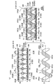
- the flexible substrate is formed in a spiral shape following the inner surface of the bending tube, and a part of the flexible substrate has a spiral portion fixed to the inner surface of the bending tube.
- the portions FPC2 that are separated for each spiral pitch PiS in the spiral portion FPC1 are arranged with a period twice the pitch Pi among the plurality of ring-shaped members 2132. It contacts the inner surface (wire insertion part 2132D) of each ring-shaped member 2132. And all each site
Landscapes
- Health & Medical Sciences (AREA)
- Life Sciences & Earth Sciences (AREA)
- Surgery (AREA)
- Engineering & Computer Science (AREA)
- Medical Informatics (AREA)
- Animal Behavior & Ethology (AREA)
- Radiology & Medical Imaging (AREA)
- Nuclear Medicine, Radiotherapy & Molecular Imaging (AREA)
- Biomedical Technology (AREA)
- Heart & Thoracic Surgery (AREA)
- Physics & Mathematics (AREA)
- Molecular Biology (AREA)
- Biophysics (AREA)
- Pathology (AREA)
- General Health & Medical Sciences (AREA)
- Public Health (AREA)
- Veterinary Medicine (AREA)
- Optics & Photonics (AREA)
- Rehabilitation Therapy (AREA)
- Gynecology & Obstetrics (AREA)
- Manufacturing & Machinery (AREA)
- Ultra Sonic Daignosis Equipment (AREA)
- Endoscopes (AREA)
Abstract
An ultrasonic endoscope is provided with: a vibrator provided on the front end side in the direction of insertion into a subject and transmitting and receiving ultrasonic waves; a bendable tube 213A provided closer to the base end side than the vibrator and having a plurality of ring-shaped members 2132 which are connected to each other in the insertion direction and which are bendable in at least two directions; a flexible tube interconnected with the base end side of the bendable tube 213A; a signal cable inserted into the flexible tube; and a flexible printed circuit board FPC inserted into the bendable tube 213A and electrically connecting the vibrator and the signal cable. The flexible printed circuit board FPC is formed in a helical shape following the shape of the inner surface of the bendable tube 213A and has a helical section FPC1, a part of which is affixed to the inner surface of the bendable tube 213A.
Description
本発明は、超音波内視鏡に関する。
The present invention relates to an ultrasonic endoscope.
従来、柔軟で細長い挿入部を人等の被検体内に挿入し、当該被検体内を観察する超音波内視鏡が知られている。このような超音波内視鏡では、挿入部は、超音波を送受信する振動子部と、振動子部より基端側に設けられ、操作部への操作に応じて湾曲可能な湾曲管と、湾曲管の基端側に連設される可撓管と、可撓管及び湾曲管の内部に挿通され、振動子部に電気的に接続する信号ケーブルとを備える。
しかしながら、このような構成では、湾曲管の湾曲動作に応じて信号ケーブルが屈曲するため、当該信号ケーブルが劣化する虞がある。
そこで、当該信号ケーブルの劣化を防止する構造として、以下の超音波内視鏡が提案されている(例えば、特許文献1参照)。
特許文献1に記載の超音波内視鏡では、信号ケーブルを湾曲管(湾曲部)内まで引き回さずに、当該湾曲管内にフレキシブル基板を配設し、当該フレキシブル基板にて振動子部(超音波プローブ)と可撓管の先端側まで引き回された信号ケーブルとを電気的に接続する構造を採用している。また、当該フレキシブル基板は、湾曲管の内部において、当該湾曲管との間に僅かに隙間を空けた状態で、当該湾曲管の軸線周りに螺旋状に巻いて配置されている。そして、当該フレキシブル基板における螺旋状の内部には、当該螺旋状の軸線に沿って、処置具を挿通するための処置具挿通チャンネル等の内蔵物が挿通されている。 2. Description of the Related Art Conventionally, an ultrasonic endoscope is known in which a flexible and elongated insertion portion is inserted into a subject such as a human and the inside of the subject is observed. In such an ultrasonic endoscope, the insertion unit includes a transducer unit that transmits and receives ultrasonic waves, a bending tube that is provided on the proximal side from the transducer unit, and can be bent according to an operation to the operation unit, A flexible tube connected to the proximal end side of the bending tube, and a signal cable inserted into the flexible tube and the bending tube and electrically connected to the vibrator unit.
However, in such a configuration, since the signal cable bends in accordance with the bending operation of the bending tube, the signal cable may be deteriorated.
Accordingly, the following ultrasonic endoscope has been proposed as a structure for preventing the signal cable from deteriorating (see, for example, Patent Document 1).
In the ultrasonic endoscope described inPatent Document 1, a flexible substrate is disposed in the bending tube without routing the signal cable into the bending tube (curving portion), and the vibrator portion ( A structure is employed in which an ultrasonic probe) is electrically connected to a signal cable routed to the distal end side of the flexible tube. In addition, the flexible substrate is disposed inside the bending tube in a spiral manner around the axis of the bending tube with a slight gap between the flexible substrate and the bending tube. A built-in object such as a treatment instrument insertion channel for inserting a treatment instrument is inserted along the spiral axis in the spiral interior of the flexible substrate.
しかしながら、このような構成では、湾曲管の湾曲動作に応じて信号ケーブルが屈曲するため、当該信号ケーブルが劣化する虞がある。
そこで、当該信号ケーブルの劣化を防止する構造として、以下の超音波内視鏡が提案されている(例えば、特許文献1参照)。
特許文献1に記載の超音波内視鏡では、信号ケーブルを湾曲管(湾曲部)内まで引き回さずに、当該湾曲管内にフレキシブル基板を配設し、当該フレキシブル基板にて振動子部(超音波プローブ)と可撓管の先端側まで引き回された信号ケーブルとを電気的に接続する構造を採用している。また、当該フレキシブル基板は、湾曲管の内部において、当該湾曲管との間に僅かに隙間を空けた状態で、当該湾曲管の軸線周りに螺旋状に巻いて配置されている。そして、当該フレキシブル基板における螺旋状の内部には、当該螺旋状の軸線に沿って、処置具を挿通するための処置具挿通チャンネル等の内蔵物が挿通されている。 2. Description of the Related Art Conventionally, an ultrasonic endoscope is known in which a flexible and elongated insertion portion is inserted into a subject such as a human and the inside of the subject is observed. In such an ultrasonic endoscope, the insertion unit includes a transducer unit that transmits and receives ultrasonic waves, a bending tube that is provided on the proximal side from the transducer unit, and can be bent according to an operation to the operation unit, A flexible tube connected to the proximal end side of the bending tube, and a signal cable inserted into the flexible tube and the bending tube and electrically connected to the vibrator unit.
However, in such a configuration, since the signal cable bends in accordance with the bending operation of the bending tube, the signal cable may be deteriorated.
Accordingly, the following ultrasonic endoscope has been proposed as a structure for preventing the signal cable from deteriorating (see, for example, Patent Document 1).
In the ultrasonic endoscope described in
ところで、フレキシブル基板は、操作部への操作に伴って、基端側に引っ張られる場合がある。特許文献1に記載の超音波内視鏡において、上述したようにフレキシブル基板が基端側に引っ張られた場合には、当該フレキシブル基板における螺旋状の内部に挿通された内蔵物を当該フレキシブル基板で締め付けることとなる。そして、このような動作(フレキシブル基板にて内蔵物を締め付ける動作)が繰り返し行われた場合には、フレキシブル基板が断線してしまうとともに、内蔵物に傷を付けてしまう、という問題がある。
By the way, the flexible substrate may be pulled toward the base end side in accordance with the operation to the operation unit. In the ultrasonic endoscope described in Patent Document 1, when the flexible substrate is pulled to the proximal end side as described above, the built-in object inserted into the spiral inside of the flexible substrate is the flexible substrate. It will be tightened. And when such operation | movement (operation | movement which clamps a built-in thing with a flexible substrate) is performed repeatedly, while a flexible substrate will be disconnected, there exists a problem that a built-in thing will be damaged.
本発明は、上記に鑑みてなされたものであって、フレキシブル基板の断線を防止するとともに、フレキシブル基板における螺旋状の内部に挿通された内蔵物に傷を付けてしまうことを防止することができる超音波内視鏡を提供することを目的とする。
The present invention has been made in view of the above, and can prevent breakage of a flexible substrate and can prevent damage to a built-in object inserted into a spiral inside of the flexible substrate. An object is to provide an ultrasonic endoscope.
上述した課題を解決し、目的を達成するために、本発明に係る超音波内視鏡は、被検体内への挿入方向の先端側に設けられ、超音波を送受信する振動子部と、前記振動子部より基端側に設けられ、前記挿入方向に沿って相互に連結されて少なくとも2方向に湾曲可能な複数のリング状部材を有する湾曲管と、前記湾曲管の基端側に連設される可撓管と、前記可撓管の内部に挿通される信号ケーブルと、前記湾曲管の内部に挿通され、前記振動子部及び前記信号ケーブルを電気的に接続するフレキシブル基板とを備え、前記フレキシブル基板は、前記湾曲管の内面に倣う螺旋状に形成され、一部が前記湾曲管の内面に固定される螺旋部を有することを特徴とする。
In order to solve the above-described problems and achieve the object, an ultrasonic endoscope according to the present invention is provided on the distal end side in the insertion direction into a subject, and a transducer unit for transmitting and receiving ultrasonic waves, A bending tube provided on the proximal end side from the transducer portion and connected to each other along the insertion direction and having a plurality of ring-shaped members that can be bent in at least two directions, and connected to the proximal end side of the bending tube A flexible tube, a signal cable inserted into the flexible tube, and a flexible substrate inserted into the curved tube and electrically connecting the vibrator unit and the signal cable, The flexible substrate is formed in a spiral shape following the inner surface of the bending tube, and a part of the flexible substrate has a spiral portion fixed to the inner surface of the bending tube.
また、本発明に係る超音波内視鏡は、上記発明において、前記螺旋部における螺旋ピッチ毎に離れた各部位は、前記リング状部材のピッチをPiとした場合に、前記複数のリング状部材のうちPi×2n(nは整数)の周期で配列される各リング状部材の内面にそれぞれ当接することを特徴とする。
Further, in the ultrasonic endoscope according to the present invention, in the above invention, each of the portions separated for each spiral pitch in the spiral portion has the plurality of ring-shaped members when the pitch of the ring-shaped member is Pi. Of the ring-shaped members arranged in a cycle of Pi × 2n (n is an integer).
また、本発明に係る超音波内視鏡は、上記発明において、前記螺旋部における螺旋ピッチ毎に離れた各部位の少なくともいずれかは、前記複数のリング状部材のうちPi×2n(nは整数)の周期で配列される各リング状部材の少なくともいずれかの内面に固定されることを特徴とする。
Moreover, in the ultrasonic endoscope according to the present invention, in the above invention, at least one of the portions separated for each spiral pitch in the spiral portion is Pi × 2n (n is an integer) among the plurality of ring-shaped members. ) Is fixed to at least one inner surface of each ring-shaped member arranged at a period of ().
また、本発明に係る超音波内視鏡は、上記発明において、前記螺旋部の幅寸法は、前記リング状部材における前記挿入方向の長さ寸法以下に設定されていることを特徴とする。
The ultrasonic endoscope according to the present invention is characterized in that, in the above invention, the width dimension of the spiral portion is set to be equal to or less than the length dimension in the insertion direction of the ring-shaped member.
また、本発明に係る超音波内視鏡は、上記発明において、前記複数のリング状部材を前記少なくとも2方向に湾曲させるワイヤを備え、前記複数のリング状部材は、前記ワイヤが挿通されるワイヤ挿通部をそれぞれ有し、前記螺旋部は、複数の前記ワイヤ挿通部の少なくともいずれかに固定されることを特徴とする。
The ultrasonic endoscope according to the present invention may further include a wire that bends the plurality of ring-shaped members in the at least two directions, and the plurality of ring-shaped members are wires through which the wires are inserted. It has an insertion part, respectively, and the spiral part is fixed to at least one of the plurality of wire insertion parts.
本発明に係る超音波内視鏡では、フレキシブル基板は、湾曲管の内面に倣う螺旋状に形成された螺旋部を有する。このため、操作部への操作に伴う湾曲管の湾曲動作にフレキシブル基板(螺旋部)を追従させ、当該フレキシブル基板が折れ曲がることを防止することができる。また、螺旋部は、一部が湾曲管の内面に固定される。このため、操作部に操作が施された場合であっても、フレキシブル基板が基端側に引っ張られることがなく、フレキシブル基板(螺旋部)が内蔵物を締め付ける動作を行うことがない。
したがって、本発明に係る超音波内視鏡によれば、フレキシブル基板の断線を防止することができるとともに、内蔵物に傷を付けてしまうことを防止することができる、という効果を奏する。 In the ultrasonic endoscope according to the present invention, the flexible substrate has a spiral portion formed in a spiral shape following the inner surface of the bending tube. For this reason, a flexible substrate (spiral part) can be made to follow the bending operation | movement of the bending tube accompanying operation to an operation part, and the said flexible substrate can be prevented from bending. Further, a part of the spiral portion is fixed to the inner surface of the bending tube. For this reason, even if it is a case where operation is performed to the operation part, a flexible substrate is not pulled to the base end side, and the flexible substrate (spiral part) does not perform the operation | movement which clamps a built-in thing.
Therefore, according to the ultrasonic endoscope according to the present invention, it is possible to prevent disconnection of the flexible substrate and to prevent the built-in object from being damaged.
以下に、図面を参照して、本発明を実施するための形態(以下、実施の形態)について説明する。なお、以下に説明する実施の形態によって本発明が限定されるものではない。さらに、図面の記載において、同一の部分には同一の符号を付している。
DETAILED DESCRIPTION Hereinafter, modes for carrying out the present invention (hereinafter referred to as embodiments) will be described with reference to the drawings. The present invention is not limited to the embodiments described below. Furthermore, the same code | symbol is attached | subjected to the same part in description of drawing.
〔内視鏡システムの概略構成〕
図1は、本発明の実施の形態に係る内視鏡システム1を模式的に示す図である。
内視鏡システム1は、超音波内視鏡を用いて人等の被検体内の超音波診断を行うシステムである。この内視鏡システム1は、図1に示すように、超音波内視鏡2と、超音波観測装置3と、内視鏡観察装置4と、表示装置5と、光源装置6とを備える。
超音波内視鏡2は、一部を被検体内に挿入可能とし、被検体内の体壁に向けて超音波パルスを送信するとともに被検体にて反射された超音波エコーを受信してエコー信号を出力する機能、及び被検体内を撮像して画像信号を出力する機能を有する。
なお、超音波内視鏡2の詳細な構成については、後述する。 [Schematic configuration of endoscope system]
FIG. 1 is a diagram schematically showing anendoscope system 1 according to an embodiment of the present invention.
Theendoscope system 1 is a system that performs ultrasonic diagnosis in a subject such as a person using an ultrasonic endoscope. As shown in FIG. 1, the endoscope system 1 includes an ultrasonic endoscope 2, an ultrasonic observation device 3, an endoscope observation device 4, a display device 5, and a light source device 6.
Theultrasonic endoscope 2 can be partially inserted into the subject, transmits an ultrasonic pulse toward the body wall in the subject, and receives and echoes an ultrasonic echo reflected from the subject. It has a function of outputting a signal and a function of imaging the inside of the subject and outputting an image signal.
The detailed configuration of theultrasonic endoscope 2 will be described later.
図1は、本発明の実施の形態に係る内視鏡システム1を模式的に示す図である。
内視鏡システム1は、超音波内視鏡を用いて人等の被検体内の超音波診断を行うシステムである。この内視鏡システム1は、図1に示すように、超音波内視鏡2と、超音波観測装置3と、内視鏡観察装置4と、表示装置5と、光源装置6とを備える。
超音波内視鏡2は、一部を被検体内に挿入可能とし、被検体内の体壁に向けて超音波パルスを送信するとともに被検体にて反射された超音波エコーを受信してエコー信号を出力する機能、及び被検体内を撮像して画像信号を出力する機能を有する。
なお、超音波内視鏡2の詳細な構成については、後述する。 [Schematic configuration of endoscope system]
FIG. 1 is a diagram schematically showing an
The
The
The detailed configuration of the
超音波観測装置3は、超音波ケーブル31(図1)を介して超音波内視鏡2に電気的に接続し、超音波ケーブル31を介して超音波内視鏡2にパルス信号を出力するとともに超音波内視鏡2からエコー信号を入力する。そして、超音波観測装置3は、当該エコー信号に所定の処理を施して超音波画像を生成する。
内視鏡観察装置4は、ビデオケーブル41(図1)を介して超音波内視鏡2に電気的に接続し、ビデオケーブル41を介して超音波内視鏡2からの画像信号を入力する。そして、内視鏡観察装置4は、当該画像信号に所定の処理を施して内視鏡画像を生成する。
表示装置5は、液晶または有機EL(Electro Luminescence)を用いて構成され、超音波観測装置3にて生成された超音波画像や、内視鏡観察装置4にて生成された内視鏡画像等を表示する。
光源装置6は、超音波内視鏡2に設けられた後述するコネクタ24(第3コネクタ部243)を介して超音波内視鏡2に接続し、被検体内を照明する照明光を超音波内視鏡2に供給する。 Theultrasonic observation apparatus 3 is electrically connected to the ultrasonic endoscope 2 via the ultrasonic cable 31 (FIG. 1), and outputs a pulse signal to the ultrasonic endoscope 2 via the ultrasonic cable 31. At the same time, an echo signal is input from the ultrasonic endoscope 2. Then, the ultrasonic observation device 3 performs a predetermined process on the echo signal to generate an ultrasonic image.
Theendoscope observation apparatus 4 is electrically connected to the ultrasonic endoscope 2 via a video cable 41 (FIG. 1) and inputs an image signal from the ultrasonic endoscope 2 via the video cable 41. . Then, the endoscope observation apparatus 4 performs a predetermined process on the image signal to generate an endoscope image.
Thedisplay device 5 is configured using liquid crystal or organic EL (Electro Luminescence), and an ultrasonic image generated by the ultrasonic observation device 3, an endoscope image generated by the endoscope observation device 4, and the like. Is displayed.
Thelight source device 6 is connected to the ultrasonic endoscope 2 via a connector 24 (third connector portion 243), which will be described later, provided on the ultrasonic endoscope 2, and the illumination light for illuminating the inside of the subject is ultrasonicated. Supplied to the endoscope 2.
内視鏡観察装置4は、ビデオケーブル41(図1)を介して超音波内視鏡2に電気的に接続し、ビデオケーブル41を介して超音波内視鏡2からの画像信号を入力する。そして、内視鏡観察装置4は、当該画像信号に所定の処理を施して内視鏡画像を生成する。
表示装置5は、液晶または有機EL(Electro Luminescence)を用いて構成され、超音波観測装置3にて生成された超音波画像や、内視鏡観察装置4にて生成された内視鏡画像等を表示する。
光源装置6は、超音波内視鏡2に設けられた後述するコネクタ24(第3コネクタ部243)を介して超音波内視鏡2に接続し、被検体内を照明する照明光を超音波内視鏡2に供給する。 The
The
The
The
〔超音波内視鏡の構成〕
超音波内視鏡2は、図1に示すように、挿入部21と、操作部22と、ユニバーサルケーブル23と、コネクタ24とを備える。
なお、以下に記載する「先端側」は、挿入部21の先端側(被検体内への挿入方向の先端側)を意味する。また、以下に記載する「基端側」は、挿入部21の先端から離間する側を意味する。
挿入部21は、被検体内に挿入される部分である。この挿入部21は、図1に示すように、先端側に設けられる超音波探触子211と、超音波探触子211の基端側に連結される硬性部材212と、硬性部材212の基端側に連結され湾曲可能とする湾曲部213と、湾曲部213の基端側に連結され可撓性を有する可撓管214とを備える。
ここで、挿入部21の内部には、光源装置6から供給された照明光を伝送するライトガイドLG(図5参照)、被写体像を基端側に伝送するイメージガイドIG(図5参照)、送気や送水等に用いられるチューブTB(図5参照)、処置具(例えば、穿刺針等)を挿通するための処置具チューブCH(図5参照)、上述したパルス信号やエコー信号を伝送する信号ケーブルCB(図2参照)、超音波探触子211を構成する後述する振動子部2111(図2参照)と信号ケーブルCBとを電気的に接続するフレキシブル基板FPC(図5参照)等が引き回されている。
なお、挿入部21の先端側の詳細な構成(超音波探触子211、硬性部材212、湾曲部213、及びフレキシブル基板FPC)については、後述する。 [Configuration of ultrasonic endoscope]
As shown in FIG. 1, theultrasonic endoscope 2 includes an insertion unit 21, an operation unit 22, a universal cable 23, and a connector 24.
The “tip side” described below means the tip side of the insertion portion 21 (tip side in the direction of insertion into the subject). The “proximal end side” described below means a side away from the distal end of theinsertion portion 21.
Theinsertion part 21 is a part inserted into the subject. As shown in FIG. 1, the insertion portion 21 includes an ultrasonic probe 211 provided on the distal end side, a rigid member 212 connected to the proximal end side of the ultrasonic probe 211, and a base of the rigid member 212. A bending portion 213 connected to the end side and capable of being bent is provided, and a flexible tube 214 connected to the proximal end side of the bending portion 213 and having flexibility.
Here, inside theinsertion portion 21, a light guide LG (see FIG. 5) that transmits the illumination light supplied from the light source device 6, an image guide IG (see FIG. 5) that transmits the subject image to the proximal side, A tube TB (see FIG. 5) used for air supply or water supply, a treatment instrument tube CH (see FIG. 5) for inserting a treatment instrument (for example, a puncture needle), and the aforementioned pulse signal and echo signal are transmitted. A signal cable CB (see FIG. 2), a flexible substrate FPC (see FIG. 5) that electrically connects a later-described transducer portion 2111 (see FIG. 2) constituting the ultrasonic probe 211 and the signal cable CB, and the like. Has been routed.
The detailed configuration of the distal end side of the insertion portion 21 (theultrasonic probe 211, the rigid member 212, the bending portion 213, and the flexible substrate FPC) will be described later.
超音波内視鏡2は、図1に示すように、挿入部21と、操作部22と、ユニバーサルケーブル23と、コネクタ24とを備える。
なお、以下に記載する「先端側」は、挿入部21の先端側(被検体内への挿入方向の先端側)を意味する。また、以下に記載する「基端側」は、挿入部21の先端から離間する側を意味する。
挿入部21は、被検体内に挿入される部分である。この挿入部21は、図1に示すように、先端側に設けられる超音波探触子211と、超音波探触子211の基端側に連結される硬性部材212と、硬性部材212の基端側に連結され湾曲可能とする湾曲部213と、湾曲部213の基端側に連結され可撓性を有する可撓管214とを備える。
ここで、挿入部21の内部には、光源装置6から供給された照明光を伝送するライトガイドLG(図5参照)、被写体像を基端側に伝送するイメージガイドIG(図5参照)、送気や送水等に用いられるチューブTB(図5参照)、処置具(例えば、穿刺針等)を挿通するための処置具チューブCH(図5参照)、上述したパルス信号やエコー信号を伝送する信号ケーブルCB(図2参照)、超音波探触子211を構成する後述する振動子部2111(図2参照)と信号ケーブルCBとを電気的に接続するフレキシブル基板FPC(図5参照)等が引き回されている。
なお、挿入部21の先端側の詳細な構成(超音波探触子211、硬性部材212、湾曲部213、及びフレキシブル基板FPC)については、後述する。 [Configuration of ultrasonic endoscope]
As shown in FIG. 1, the
The “tip side” described below means the tip side of the insertion portion 21 (tip side in the direction of insertion into the subject). The “proximal end side” described below means a side away from the distal end of the
The
Here, inside the
The detailed configuration of the distal end side of the insertion portion 21 (the
操作部22は、挿入部21の基端側に連結され、医師等からの各種操作を受け付ける部分である。この操作部22は、図1に示すように、湾曲部213を湾曲操作するための湾曲ノブ221と、各種操作を行うための複数の操作部材222とを備える。
また、操作部22には、挿入部21内に配設された処置具チューブCHに連通し、当該処置具チューブCHに処置具を挿通するための処置具挿入口223が形成されている。
さらに、操作部22の内部には、イメージガイドIGにて伝送された被写体像を撮像して画像信号を出力する撮像素子(図示略)と、イメージガイドIGにて伝送された被写体像を当該撮像素子に結像する光学系(図示略)とが配設されている。 Theoperation unit 22 is connected to the proximal end side of the insertion unit 21 and is a part that receives various operations from a doctor or the like. As shown in FIG. 1, the operation unit 22 includes a bending knob 221 for bending the bending portion 213 and a plurality of operation members 222 for performing various operations.
In addition, a treatmentinstrument insertion port 223 is formed in the operation section 22 so as to communicate with the treatment instrument tube CH disposed in the insertion section 21 and to insert the treatment instrument into the treatment instrument tube CH.
Further, inside theoperation unit 22, an imaging element (not shown) that captures the subject image transmitted by the image guide IG and outputs an image signal, and captures the subject image transmitted by the image guide IG. An optical system (not shown) that forms an image on the element is disposed.
また、操作部22には、挿入部21内に配設された処置具チューブCHに連通し、当該処置具チューブCHに処置具を挿通するための処置具挿入口223が形成されている。
さらに、操作部22の内部には、イメージガイドIGにて伝送された被写体像を撮像して画像信号を出力する撮像素子(図示略)と、イメージガイドIGにて伝送された被写体像を当該撮像素子に結像する光学系(図示略)とが配設されている。 The
In addition, a treatment
Further, inside the
ユニバーサルケーブル23は、操作部22から延在し、各種信号を伝送する複数の信号ケーブル(図示略)、及び光源装置6から供給された照明光を伝送する光ファイバ(図示略)等が配設されたケーブルである。
コネクタ24は、ユニバーサルケーブル23の端部に設けられている。そして、コネクタ24は、超音波ケーブル31、ビデオケーブル41、及び光源装置6がそれぞれ接続される第1~第3コネクタ部241~243を備える。 Theuniversal cable 23 extends from the operation unit 22 and includes a plurality of signal cables (not shown) that transmit various signals, an optical fiber (not shown) that transmits illumination light supplied from the light source device 6, and the like. Cable.
Theconnector 24 is provided at the end of the universal cable 23. The connector 24 includes first to third connector portions 241 to 243 to which the ultrasonic cable 31, the video cable 41, and the light source device 6 are respectively connected.
コネクタ24は、ユニバーサルケーブル23の端部に設けられている。そして、コネクタ24は、超音波ケーブル31、ビデオケーブル41、及び光源装置6がそれぞれ接続される第1~第3コネクタ部241~243を備える。 The
The
〔挿入部の構成〕
図2は、挿入部21の先端側を拡大した斜視図である。
以下、超音波探触子211、硬性部材212、湾曲部213、及びフレキシブル基板FPCの構成について順に説明する。 (Composition of insertion part)
FIG. 2 is an enlarged perspective view of the distal end side of theinsertion portion 21.
Hereinafter, the configurations of theultrasonic probe 211, the rigid member 212, the bending portion 213, and the flexible substrate FPC will be described in order.
図2は、挿入部21の先端側を拡大した斜視図である。
以下、超音波探触子211、硬性部材212、湾曲部213、及びフレキシブル基板FPCの構成について順に説明する。 (Composition of insertion part)
FIG. 2 is an enlarged perspective view of the distal end side of the
Hereinafter, the configurations of the
〔超音波探触子の構成〕
超音波探触子211は、図2に示すように、コンベックス型の超音波探触子であり、複数の超音波振動子が凸型の円弧を形成するように規則的に配列されてなる振動子部2111を有する。
ここで、超音波振動子は、音響レンズ、圧電素子、及び整合層を有し、被検体内の体壁よりも内部の超音波断層画像に寄与する超音波エコーを取得する。
そして、振動子部2111は、挿入部21の内部に引き回されたフレキシブル基板FPC及び信号ケーブルCBを介して超音波観測装置3から入力したパルス信号を超音波パルスに変換して被検体内に送信する。また、振動子部2111は、被検体内で反射された超音波エコーを電気的なエコー信号に変換し、挿入部21の内部に引き回されたフレキシブル基板FPC及び信号ケーブルCBを介して超音波観測装置3に出力する。 [Configuration of ultrasonic probe]
As shown in FIG. 2, theultrasonic probe 211 is a convex ultrasonic probe, and is a vibration in which a plurality of ultrasonic transducers are regularly arranged so as to form a convex arc. A child portion 2111 is included.
Here, the ultrasonic transducer has an acoustic lens, a piezoelectric element, and a matching layer, and acquires an ultrasonic echo that contributes to an internal ultrasonic tomographic image rather than a body wall in the subject.
Then, thetransducer unit 2111 converts the pulse signal input from the ultrasonic observation device 3 through the flexible substrate FPC and the signal cable CB routed inside the insertion unit 21 into an ultrasonic pulse, and enters the subject. Send. In addition, the transducer unit 2111 converts the ultrasonic echo reflected in the subject into an electrical echo signal, and transmits the ultrasonic wave via the flexible substrate FPC and the signal cable CB routed inside the insertion unit 21. Output to the observation device 3.
超音波探触子211は、図2に示すように、コンベックス型の超音波探触子であり、複数の超音波振動子が凸型の円弧を形成するように規則的に配列されてなる振動子部2111を有する。
ここで、超音波振動子は、音響レンズ、圧電素子、及び整合層を有し、被検体内の体壁よりも内部の超音波断層画像に寄与する超音波エコーを取得する。
そして、振動子部2111は、挿入部21の内部に引き回されたフレキシブル基板FPC及び信号ケーブルCBを介して超音波観測装置3から入力したパルス信号を超音波パルスに変換して被検体内に送信する。また、振動子部2111は、被検体内で反射された超音波エコーを電気的なエコー信号に変換し、挿入部21の内部に引き回されたフレキシブル基板FPC及び信号ケーブルCBを介して超音波観測装置3に出力する。 [Configuration of ultrasonic probe]
As shown in FIG. 2, the
Here, the ultrasonic transducer has an acoustic lens, a piezoelectric element, and a matching layer, and acquires an ultrasonic echo that contributes to an internal ultrasonic tomographic image rather than a body wall in the subject.
Then, the
〔硬性部材の構成〕
硬性部材212には、図2に示すように、取付用孔2121と、処置具チャンネル2122と、撮像用孔2123と、照明用孔2124とが形成されている。
取付用孔2121は、超音波探触子211が取り付けられる孔である。
処置具チャンネル2122は、処置具挿入口223を介して処置具チューブCHに挿通された各種処置具を外部に突出させる孔である。
撮像用孔2123は、内部にイメージガイドIGの一端が配設され、被写体像を当該イメージガイドIGの一端に取り込む孔である。
照明用孔2124は、内部にライトガイドLGの一端が配設され、ライトガイドLGを介して伝送された照明光を被写体内に照明する孔である。 [Configuration of rigid member]
As shown in FIG. 2, therigid member 212 has a mounting hole 2121, a treatment instrument channel 2122, an imaging hole 2123, and an illumination hole 2124.
Theattachment hole 2121 is a hole to which the ultrasonic probe 211 is attached.
Thetreatment instrument channel 2122 is a hole through which various treatment instruments inserted into the treatment instrument tube CH through the treatment instrument insertion port 223 protrude.
Theimage pickup hole 2123 is a hole in which one end of the image guide IG is disposed, and a subject image is taken into one end of the image guide IG.
Theillumination hole 2124 is a hole in which one end of the light guide LG is disposed to illuminate the illumination light transmitted through the light guide LG in the subject.
硬性部材212には、図2に示すように、取付用孔2121と、処置具チャンネル2122と、撮像用孔2123と、照明用孔2124とが形成されている。
取付用孔2121は、超音波探触子211が取り付けられる孔である。
処置具チャンネル2122は、処置具挿入口223を介して処置具チューブCHに挿通された各種処置具を外部に突出させる孔である。
撮像用孔2123は、内部にイメージガイドIGの一端が配設され、被写体像を当該イメージガイドIGの一端に取り込む孔である。
照明用孔2124は、内部にライトガイドLGの一端が配設され、ライトガイドLGを介して伝送された照明光を被写体内に照明する孔である。 [Configuration of rigid member]
As shown in FIG. 2, the
The
The
The
The
〔湾曲部の構成〕
湾曲部213は、図2に示すように、基端ベース2131、複数のリング状部材2132、及び先端ベース2133を有する湾曲管213Aと、シールド部材2134(図5参照)と、被覆部材2135(図5参照)とを備える。なお、図2では、説明の便宜上、シールド部材2134及び被覆部材2135の図示を省略(湾曲管213Aのみを図示)している。
基端ベース2131は、円筒形状を有し、基端側が可撓管214に連結する。
先端ベース2133は、円筒形状を有し、先端側が硬性部材212に連結する。
シールド部材2134は、EMC対策やノイズ対策を目的とした金属メッシュ等のシールド部材であり、湾曲管213Aの外周を被覆する部材である。
被覆部材2135は、ゴム等の柔軟な材質で構成され、シールド部材2134の外周を被覆する部材である。 (Structure of the curved part)
As shown in FIG. 2, the bendingportion 213 includes a bending tube 213A having a proximal end base 2131, a plurality of ring-shaped members 2132, and a distal end base 2133, a shield member 2134 (see FIG. 5), and a covering member 2135 (see FIG. 5). In FIG. 2, for convenience of explanation, illustration of the shield member 2134 and the covering member 2135 is omitted (only the curved tube 213A is shown).
Theproximal end base 2131 has a cylindrical shape, and the proximal end side is connected to the flexible tube 214.
Thedistal end base 2133 has a cylindrical shape, and the distal end side is connected to the rigid member 212.
Theshield member 2134 is a shield member such as a metal mesh for the purpose of EMC countermeasures and noise countermeasures, and is a member that covers the outer periphery of the bending tube 213A.
The coveringmember 2135 is made of a flexible material such as rubber and is a member that covers the outer periphery of the shield member 2134.
湾曲部213は、図2に示すように、基端ベース2131、複数のリング状部材2132、及び先端ベース2133を有する湾曲管213Aと、シールド部材2134(図5参照)と、被覆部材2135(図5参照)とを備える。なお、図2では、説明の便宜上、シールド部材2134及び被覆部材2135の図示を省略(湾曲管213Aのみを図示)している。
基端ベース2131は、円筒形状を有し、基端側が可撓管214に連結する。
先端ベース2133は、円筒形状を有し、先端側が硬性部材212に連結する。
シールド部材2134は、EMC対策やノイズ対策を目的とした金属メッシュ等のシールド部材であり、湾曲管213Aの外周を被覆する部材である。
被覆部材2135は、ゴム等の柔軟な材質で構成され、シールド部材2134の外周を被覆する部材である。 (Structure of the curved part)
As shown in FIG. 2, the bending
The
The
The
The covering
図3は、リング状部材2132を示す斜視図である。
複数のリング状部材2132は、同一の形状を有する。このため、以下では、一つのリング状部材2132の形状のみ説明する。
リング状部材2132は、図3に示すように、円筒状の基体2132Aと、2つの第1張出部2132Bと、2つの第2張出部2132Cと、2つのワイヤ挿通部2132Dとを備える。
2つの第1張出部2132Bは、基体2132Aの先端側の端部において、当該基体2132Aの中心軸を基準として180°の回転対称となる位置からそれぞれ先端側に張り出した部分である。そして、2つの第1張出部2132Bには、表裏を貫通し(基体2132Aの中心軸に直交する方向に貫通し)、ピンPN(図2)が挿通される第1ピン挿通孔2132Eがそれぞれ形成されている。
2つの第2張出部2132Cは、基体2132Aの基端側の端部において、2つの第1張出部2132Bに対向する位置からそれぞれ基端側に張り出した部分である。そして、2つの第2張出部2132Cには、第1張出部2132Bと同様に、表裏を貫通し、ピンPNが挿通される第2ピン挿通孔2132Fがそれぞれ形成されている。 FIG. 3 is a perspective view showing the ring-shapedmember 2132.
The plurality of ring-shapedmembers 2132 have the same shape. For this reason, only the shape of one ring-shaped member 2132 will be described below.
As shown in FIG. 3, the ring-shapedmember 2132 includes a cylindrical base 2132A, two first overhang portions 2132B, two second overhang portions 2132C, and two wire insertion portions 2132D.
The two first projectingportions 2132B are portions projecting toward the distal end side from positions that are 180 ° rotationally symmetric with respect to the central axis of the base body 2132A at the end portion on the distal end side of the base body 2132A. The two first projecting portions 2132B have first pin insertion holes 2132E that penetrate the front and back (penetrate in a direction orthogonal to the central axis of the base 2132A) and through which the pin PN (FIG. 2) is inserted. Is formed.
The two second projectingportions 2132C are portions projecting from the position facing the two first projecting portions 2132B to the proximal end side at the proximal end side of the base 2132A. Similarly to the first overhanging portion 2132B, the second overhanging portions 2132C are formed with second pin insertion holes 2132F that penetrate the front and back surfaces and through which the pin PN is inserted.
複数のリング状部材2132は、同一の形状を有する。このため、以下では、一つのリング状部材2132の形状のみ説明する。
リング状部材2132は、図3に示すように、円筒状の基体2132Aと、2つの第1張出部2132Bと、2つの第2張出部2132Cと、2つのワイヤ挿通部2132Dとを備える。
2つの第1張出部2132Bは、基体2132Aの先端側の端部において、当該基体2132Aの中心軸を基準として180°の回転対称となる位置からそれぞれ先端側に張り出した部分である。そして、2つの第1張出部2132Bには、表裏を貫通し(基体2132Aの中心軸に直交する方向に貫通し)、ピンPN(図2)が挿通される第1ピン挿通孔2132Eがそれぞれ形成されている。
2つの第2張出部2132Cは、基体2132Aの基端側の端部において、2つの第1張出部2132Bに対向する位置からそれぞれ基端側に張り出した部分である。そして、2つの第2張出部2132Cには、第1張出部2132Bと同様に、表裏を貫通し、ピンPNが挿通される第2ピン挿通孔2132Fがそれぞれ形成されている。 FIG. 3 is a perspective view showing the ring-shaped
The plurality of ring-shaped
As shown in FIG. 3, the ring-shaped
The two first projecting
The two second projecting
そして、複数のリング状部材2132のうち2つのリング状部材2132は、一方のリング状部材2132の各第1張出部2132Bと、他方のリング状部材2132の各第2張出部2132Cとを互いに重ね合わせ、各第1,第2ピン挿通孔2132E,2132FにピンPNをそれぞれ挿通することで互いに連結される。すなわち、複数のリング状部材2132は、上述した連結構造により、被検体内への挿入方向に沿って相互に連結されるとともに、ピンPNを介して回動自在(図2中、上下方向に回動自在)となる。
また、上述したように相互に連結された複数のリング状部材2132のうち、基端に位置するリング状部材2132は、基端ベース2131の先端側にピンPNを介して回動自在に連結される。先端に位置するリング状部材2132は、先端ベース2133の基端側にピンPNを介して回動自在に連結される。 Of the plurality of ring-shapedmembers 2132, two ring-shaped members 2132 include first projecting portions 2132 </ b> B of one ring-shaped member 2132 and second projecting portions 2132 </ b> C of the other ring-shaped member 2132. They are overlapped with each other and connected to each other by inserting the pin PN into each of the first and second pin insertion holes 2132E and 2132F. That is, the plurality of ring-shaped members 2132 are connected to each other along the insertion direction into the subject by the above-described connection structure, and are rotatable via the pin PN (in FIG. Moveable).
In addition, among the plurality of ring-shapedmembers 2132 connected to each other as described above, the ring-shaped member 2132 positioned at the proximal end is rotatably coupled to the distal end side of the proximal end base 2131 via the pin PN. The The ring-shaped member 2132 located at the distal end is rotatably connected to the proximal end side of the distal end base 2133 via a pin PN.
また、上述したように相互に連結された複数のリング状部材2132のうち、基端に位置するリング状部材2132は、基端ベース2131の先端側にピンPNを介して回動自在に連結される。先端に位置するリング状部材2132は、先端ベース2133の基端側にピンPNを介して回動自在に連結される。 Of the plurality of ring-shaped
In addition, among the plurality of ring-shaped
2つのワイヤ挿通部2132Dは、2本のアングルワイヤAW(本発明に係るワイヤに相当(図2))がそれぞれ挿通される部分である。そして、2つのワイヤ挿通部2132Dは、図3に示すように、基体2132Aにおいて、当該基体2132Aの中心軸を基準として、各第1,第2張出部2132B,2132Cを90°回転させた位置にそれぞれ設けられている。
具体的に、基体2132Aにおいて、当該基体2132Aの中心軸を基準として、各第1,第2張出部2132B,2132Cを90°回転させた位置には、当該基体2132Aの周方向に沿って延び、当該基体2132Aの中心軸に沿って互いに対向する一対のスリット孔2132G(図3)がそれぞれ形成されている。そして、2つのワイヤ挿通部2132Dは、基体2132Aにおいて、各一対のスリット孔2132Gの内側に位置する各部位が当該基体2132Aの中心軸に向けてそれぞれ折り曲げられた部分である。 The twowire insertion portions 2132D are portions through which two angle wires AW (corresponding to wires according to the present invention (FIG. 2)) are inserted. As shown in FIG. 3, the two wire insertion portions 2132 </ b> D are positions where the first and second projecting portions 2132 </ b> B and 2132 </ b> C are rotated 90 ° with respect to the central axis of the base 2132 </ b> A in the base 2132 </ b> A. Are provided respectively.
Specifically, in thebase 2132A, the first and second projecting portions 2132B and 2132C are rotated by 90 ° with respect to the central axis of the base 2132A, and extend along the circumferential direction of the base 2132A. A pair of slit holes 2132G (FIG. 3) facing each other are formed along the central axis of the base 2132A. The two wire insertion portions 2132D are portions of the base 2132A where the portions located inside the pair of slit holes 2132G are bent toward the central axis of the base 2132A.
具体的に、基体2132Aにおいて、当該基体2132Aの中心軸を基準として、各第1,第2張出部2132B,2132Cを90°回転させた位置には、当該基体2132Aの周方向に沿って延び、当該基体2132Aの中心軸に沿って互いに対向する一対のスリット孔2132G(図3)がそれぞれ形成されている。そして、2つのワイヤ挿通部2132Dは、基体2132Aにおいて、各一対のスリット孔2132Gの内側に位置する各部位が当該基体2132Aの中心軸に向けてそれぞれ折り曲げられた部分である。 The two
Specifically, in the
そして、2本のアングルワイヤAWは、図2に示すように、基体2132Aとワイヤ挿通部2132Dとの間を通るように、複数のリング状部材2132に挿通される。2本のアングルワイヤAWは、一端が湾曲ノブ221に接続され、他端が先端ベース2133に接続される。すなわち、医師等により湾曲ノブ221が操作されることで2本のアングルワイヤAWが適宜、牽引、開放され、湾曲管213A(湾曲部213)は、図2中、上方向及び下方向の2つの方向に湾曲する。
Then, as shown in FIG. 2, the two angle wires AW are inserted into the plurality of ring-shaped members 2132 so as to pass between the base 2132A and the wire insertion part 2132D. The two angle wires AW have one end connected to the bending knob 221 and the other end connected to the tip base 2133. That is, when the bending knob 221 is operated by a doctor or the like, the two angle wires AW are appropriately pulled and released, and the bending tube 213A (the bending portion 213) is moved upward and downward in FIG. Curve in the direction.
〔フレキシブル基板の構成〕
図4及び図5は、湾曲部213の内部に配設されるフレキシブル基板FPCの配設状態を示す図である。具体的に、図4(a)は、2つのワイヤ挿通部2132Dを通る平面(湾曲管213Aの中心軸Ax1を含む平面)にて湾曲管213Aを切断した断面図である。図4(b)は、フレキシブル基板FPCを側方から見た図である。図4(c)は、図4(a)に対応した断面図であって、湾曲管213Aの内部におけるフレキシブル基板FPCの配設状態を示す図である。なお、図4では、説明の便宜上、図2と同様に、シールド部材2134及び被覆部材2135の図示を省略(湾曲管213Aのみを図示)している。図5は、湾曲管213Aの中心軸Ax1に直交する平面にて湾曲部213を切断した断面図である。なお、図5では、説明の便宜上、フレキシブル基板FPCを二点鎖線で図示している。
フレキシブル基板FPCは、ポリイミド等の絶縁材料から構成された長尺状のシートに導体パターンが形成されたものであり、湾曲管213Aの内部に挿通されている。そして、フレキシブル基板FPCは、導体パターンを介して、振動子部2111と可撓管214の先端側まで引き回された信号ケーブルCBとを電気的に接続する。 [Configuration of flexible substrate]
4 and 5 are diagrams showing the arrangement state of the flexible substrate FPC arranged inside the bendingportion 213. FIG. Specifically, FIG. 4A is a cross-sectional view of the bending tube 213A cut along a plane passing through the two wire insertion portions 2132D (a plane including the central axis Ax1 of the bending tube 213A). FIG. 4B is a view of the flexible substrate FPC as viewed from the side. FIG. 4C is a cross-sectional view corresponding to FIG. 4A, and is a view showing an arrangement state of the flexible substrate FPC inside the bending tube 213A. In FIG. 4, for convenience of explanation, illustration of the shield member 2134 and the covering member 2135 is omitted (only the curved tube 213 </ b> A is shown), as in FIG. 2. FIG. 5 is a cross-sectional view of the bending portion 213 cut along a plane orthogonal to the central axis Ax1 of the bending tube 213A. In FIG. 5, for convenience of explanation, the flexible substrate FPC is illustrated by a two-dot chain line.
The flexible substrate FPC is formed by forming a conductive pattern on a long sheet made of an insulating material such as polyimide, and is inserted into the bendingtube 213A. The flexible substrate FPC electrically connects the vibrator portion 2111 and the signal cable CB routed to the distal end side of the flexible tube 214 via the conductor pattern.
図4及び図5は、湾曲部213の内部に配設されるフレキシブル基板FPCの配設状態を示す図である。具体的に、図4(a)は、2つのワイヤ挿通部2132Dを通る平面(湾曲管213Aの中心軸Ax1を含む平面)にて湾曲管213Aを切断した断面図である。図4(b)は、フレキシブル基板FPCを側方から見た図である。図4(c)は、図4(a)に対応した断面図であって、湾曲管213Aの内部におけるフレキシブル基板FPCの配設状態を示す図である。なお、図4では、説明の便宜上、図2と同様に、シールド部材2134及び被覆部材2135の図示を省略(湾曲管213Aのみを図示)している。図5は、湾曲管213Aの中心軸Ax1に直交する平面にて湾曲部213を切断した断面図である。なお、図5では、説明の便宜上、フレキシブル基板FPCを二点鎖線で図示している。
フレキシブル基板FPCは、ポリイミド等の絶縁材料から構成された長尺状のシートに導体パターンが形成されたものであり、湾曲管213Aの内部に挿通されている。そして、フレキシブル基板FPCは、導体パターンを介して、振動子部2111と可撓管214の先端側まで引き回された信号ケーブルCBとを電気的に接続する。 [Configuration of flexible substrate]
4 and 5 are diagrams showing the arrangement state of the flexible substrate FPC arranged inside the bending
The flexible substrate FPC is formed by forming a conductive pattern on a long sheet made of an insulating material such as polyimide, and is inserted into the bending
具体的に、フレキシブル基板FPCは、図4または図5に示すように、湾曲管213Aの中心軸Ax1(図4(a))に平行な仮想的な直線Ax2(図4(b))を中心とする螺旋形状を有する螺旋部FPC1を有する。なお、フレキシブル基板FPCにおいて、振動子部2111に電気的に接続する一端側の一部、及び信号ケーブルCBに電気的に接続する他端側の一部以外は、全て螺旋部FPC1で構成されている。
本実施の形態では、螺旋部FPC1の外径寸法D1(図4(b))は、湾曲管213A(基体2132A)の内径寸法D2(図4(a))と同一に設定されている。また、フレキシブル基板FPCの幅寸法D3(図4(b))は、基体2132Aにおける中心軸Ax1に平行な方向(被検体内への挿入方向)の長さ寸法D4(図4(a))と同一に設定されている。さらに、螺旋部FPC1の螺旋ピッチPiS(図4(b))は、リング状部材2132のピッチPi(図4(a))の2倍に設定されている。 Specifically, as shown in FIG. 4 or 5, the flexible substrate FPC is centered on a virtual straight line Ax2 (FIG. 4 (b)) parallel to the central axis Ax1 (FIG. 4 (a)) of the bendingtube 213A. And a spiral portion FPC1 having a spiral shape. In the flexible substrate FPC, all of the flexible substrate FPC except the part on one end side electrically connected to the vibrator part 2111 and the part on the other end side electrically connected to the signal cable CB are all configured by the spiral part FPC1. Yes.
In the present embodiment, the outer diameter D1 (FIG. 4B) of the spiral portion FPC1 is set to be the same as the inner diameter D2 (FIG. 4A) of the bendingtube 213A (base 2132A). The width dimension D3 (FIG. 4B) of the flexible substrate FPC is the same as the length dimension D4 (FIG. 4A) in the direction parallel to the central axis Ax1 in the base 2132A (insertion direction into the subject). They are set the same. Further, the helical pitch PiS (FIG. 4B) of the spiral portion FPC1 is set to be twice the pitch Pi of the ring-shaped member 2132 (FIG. 4A).
本実施の形態では、螺旋部FPC1の外径寸法D1(図4(b))は、湾曲管213A(基体2132A)の内径寸法D2(図4(a))と同一に設定されている。また、フレキシブル基板FPCの幅寸法D3(図4(b))は、基体2132Aにおける中心軸Ax1に平行な方向(被検体内への挿入方向)の長さ寸法D4(図4(a))と同一に設定されている。さらに、螺旋部FPC1の螺旋ピッチPiS(図4(b))は、リング状部材2132のピッチPi(図4(a))の2倍に設定されている。 Specifically, as shown in FIG. 4 or 5, the flexible substrate FPC is centered on a virtual straight line Ax2 (FIG. 4 (b)) parallel to the central axis Ax1 (FIG. 4 (a)) of the bending
In the present embodiment, the outer diameter D1 (FIG. 4B) of the spiral portion FPC1 is set to be the same as the inner diameter D2 (FIG. 4A) of the bending
そして、フレキシブル基板FPCは、湾曲管213Aの内部において、以下に示すように配設される。
すなわち、螺旋部FPC1は、湾曲管213Aの内面に倣って配設される。また、螺旋部FPC1における螺旋ピッチPiS毎に離れた各部位FPC2は、図4(c)または図5に示すように、複数のリング状部材2132のうちピッチPiの2倍の周期で配列される各リング状部材2132の内面(2つのワイヤ挿通部2132Dのうち一方のワイヤ挿通部2132D)に当接する。この際、各部位FPC2は、図4(c)に示すように、各リング状部材2132の外部にはみ出すことなく、各リング状部材2132の内部に位置付けられる。そして、各ワイヤ挿通部2132Dに当接した全ての各部位FPC2は、当該各ワイヤ挿通部2132Dに対して、接着剤や半田等により固定される。 The flexible substrate FPC is disposed inside the bendingtube 213A as shown below.
That is, the spiral portion FPC1 is disposed following the inner surface of the bendingtube 213A. Further, the portions FPC2 separated by the spiral pitch PiS in the spiral portion FPC1 are arranged at a period twice as long as the pitch Pi among the plurality of ring-shaped members 2132 as shown in FIG. 4 (c) or FIG. Each ring-shaped member 2132 contacts the inner surface (one of the two wire insertion portions 2132D, one wire insertion portion 2132D). At this time, each part FPC2 is positioned inside each ring-shaped member 2132 without protruding outside each ring-shaped member 2132 as shown in FIG. And all each site | part FPC2 contact | abutted to each wire penetration part 2132D is fixed with respect to the said each wire penetration part 2132D with an adhesive agent, solder, etc. FIG.
すなわち、螺旋部FPC1は、湾曲管213Aの内面に倣って配設される。また、螺旋部FPC1における螺旋ピッチPiS毎に離れた各部位FPC2は、図4(c)または図5に示すように、複数のリング状部材2132のうちピッチPiの2倍の周期で配列される各リング状部材2132の内面(2つのワイヤ挿通部2132Dのうち一方のワイヤ挿通部2132D)に当接する。この際、各部位FPC2は、図4(c)に示すように、各リング状部材2132の外部にはみ出すことなく、各リング状部材2132の内部に位置付けられる。そして、各ワイヤ挿通部2132Dに当接した全ての各部位FPC2は、当該各ワイヤ挿通部2132Dに対して、接着剤や半田等により固定される。 The flexible substrate FPC is disposed inside the bending
That is, the spiral portion FPC1 is disposed following the inner surface of the bending
以上説明した本実施の形態に係る超音波内視鏡2では、フレキシブル基板FPCは、湾曲管213Aの内面に倣う螺旋状に形成された螺旋部FPC1を有する。このため、操作部22への操作に伴う湾曲管213A(湾曲部213)の湾曲動作にフレキシブル基板FPC(螺旋部FPC1)を追従させ、当該フレキシブル基板FPCが折れ曲がることを防止することができる。また、螺旋部FPC1は、一部が湾曲管213Aの内面に固定される。このため、操作部22に操作が施された場合であっても、フレキシブル基板FPCが基端側に引っ張られることがなく、フレキシブル基板FPC(螺旋部FPC1)が内蔵物(ライトガイドLG、イメージガイドIG、チューブTB、処置具チューブCH等)を締め付ける動作を行うことがない。
したがって、本実施の形態に係る超音波内視鏡2によれば、フレキシブル基板FPCの断線を防止することができる、という効果を奏する。また、フレキシブル基板FPCが内蔵物を締め付ける動作を行うことがないため、当該内蔵物に傷が付くこともない。 In theultrasonic endoscope 2 according to the present embodiment described above, the flexible substrate FPC has a spiral portion FPC1 formed in a spiral shape following the inner surface of the bending tube 213A. For this reason, it is possible to cause the flexible substrate FPC (spiral portion FPC1) to follow the bending operation of the bending tube 213A (the bending portion 213) accompanying the operation of the operation portion 22, and to prevent the flexible substrate FPC from being bent. Further, a part of the spiral portion FPC1 is fixed to the inner surface of the bending tube 213A. For this reason, even when the operation unit 22 is operated, the flexible substrate FPC is not pulled toward the base end side, and the flexible substrate FPC (spiral portion FPC1) is built-in (light guide LG, image guide). IG, tube TB, treatment instrument tube CH, etc.) are not tightened.
Therefore, according to theultrasonic endoscope 2 according to the present embodiment, there is an effect that the disconnection of the flexible substrate FPC can be prevented. Further, since the flexible substrate FPC does not perform an operation of tightening the built-in object, the built-in object is not damaged.
したがって、本実施の形態に係る超音波内視鏡2によれば、フレキシブル基板FPCの断線を防止することができる、という効果を奏する。また、フレキシブル基板FPCが内蔵物を締め付ける動作を行うことがないため、当該内蔵物に傷が付くこともない。 In the
Therefore, according to the
特に、湾曲管213Aが湾曲動作を行うため、当該湾曲管213Aの内部に配設されるフレキシブル基板FPC(螺旋部FPC1)も当該湾曲動作に応じて、当該湾曲管213Aに対して動き易い(暴れ易い)ものとなる。すなわち、動きの小さい可撓管214ではなく、動きの大きい湾曲管213Aの内面に螺旋部FPC1の一部を固定することにより、湾曲管213Aの湾曲動作に螺旋部FPC1を追従させ、当該湾曲管213Aに対する螺旋部FPC1の動き(暴れ)を抑制することができる。そして、当該湾曲管213Aに対する螺旋部FPC1の動きを抑制することで、フレキシブル基板FPCの断線、及び、内蔵物への傷付けを効果的に防止することができる。
In particular, since the bending tube 213A performs a bending operation, the flexible substrate FPC (spiral portion FPC1) disposed inside the bending tube 213A is also easy to move with respect to the bending tube 213A according to the bending operation. Easy). That is, by fixing a part of the spiral portion FPC1 to the inner surface of the bending tube 213A having a large movement instead of the flexible tube 214 having a small movement, the spiral portion FPC1 is caused to follow the bending operation of the bending tube 213A. The movement (rambling) of the spiral portion FPC1 with respect to 213A can be suppressed. Then, by suppressing the movement of the spiral portion FPC1 with respect to the bending tube 213A, it is possible to effectively prevent disconnection of the flexible substrate FPC and damage to the built-in object.
また、本実施の形態に係る超音波内視鏡2では、螺旋部FPC1における螺旋ピッチPiS毎に離れた各部位FPC2は、複数のリング状部材2132のうちピッチPiの2倍の周期で配列される各リング状部材2132の内面(ワイヤ挿通部2132D)に当接する。そして、各ワイヤ挿通部2132Dに当接した全ての各部位FPC2は、当該各ワイヤ挿通部2132Dに対して、接着剤や半田等により固定される。このため、湾曲管213Aと螺旋部FPC1とを一体化し、湾曲管213Aの湾曲動作に螺旋部FPC1を確実に追従させることができる。すなわち、湾曲管213Aに対する螺旋部FPC1の動きを防止することで、フレキシブル基板FPCの断線、及び内蔵物への傷付けを効果的に防止することができるとともに、湾曲管213Aの湾曲力量を低減して操作性を向上させることができる。
Further, in the ultrasonic endoscope 2 according to the present embodiment, the portions FPC2 that are separated for each spiral pitch PiS in the spiral portion FPC1 are arranged with a period twice the pitch Pi among the plurality of ring-shaped members 2132. It contacts the inner surface (wire insertion part 2132D) of each ring-shaped member 2132. And all each site | part FPC2 contact | abutted to each wire penetration part 2132D is fixed with respect to the said each wire penetration part 2132D with an adhesive agent, solder, etc. FIG. Therefore, the bending tube 213A and the spiral portion FPC1 can be integrated, and the spiral portion FPC1 can reliably follow the bending operation of the bending tube 213A. That is, by preventing the movement of the spiral portion FPC1 with respect to the bending tube 213A, it is possible to effectively prevent disconnection of the flexible substrate FPC and damage to the built-in object, and reduce the amount of bending force of the bending tube 213A. Operability can be improved.
特に、ワイヤ挿通部2132Dは、湾曲管213Aの湾曲動作の際、リング状部材2132において、最も動きが大きい部分である。このため、動きの大きいワイヤ挿通部2132Dに螺旋部FPC1を固定することにより、湾曲管213Aの湾曲動作に螺旋部FPC1を確実に追従させることができる。
また、フレキシブル基板FPCの幅寸法D3は、基体2132Aにおける中心軸Ax1に平行な方向の長さ寸法D4と同一に設定されている。そして、各部位FPC2は、各リング状部材2132の外部にはみ出すことなく、各リング状部材2132の内部に位置付けられる。このため、湾曲管213Aの湾曲動作の際、各部位FPC2が隣接するリング状部材2132に機械的に干渉することがない。したがって、各部位FPC2が各リング状部材2132の外部にはみ出した場合と比較して、湾曲管213Aの湾曲力量をさらに低減し、操作性を向上させることができる。 In particular, thewire insertion portion 2132D is the portion with the largest movement in the ring-shaped member 2132 during the bending operation of the bending tube 213A. For this reason, by fixing the spiral portion FPC1 to the wire insertion portion 2132D having a large movement, the spiral portion FPC1 can reliably follow the bending operation of the bending tube 213A.
In addition, the width dimension D3 of the flexible substrate FPC is set to be the same as the length dimension D4 in the direction parallel to the central axis Ax1 in thebase body 2132A. Each part FPC2 is positioned inside each ring-shaped member 2132 without protruding outside each ring-shaped member 2132. For this reason, during the bending operation of the bending tube 213A, each part FPC2 does not mechanically interfere with the adjacent ring-shaped member 2132. Therefore, the amount of bending force of the bending tube 213A can be further reduced and the operability can be improved as compared with the case where each portion FPC2 protrudes outside the ring-shaped member 2132.
また、フレキシブル基板FPCの幅寸法D3は、基体2132Aにおける中心軸Ax1に平行な方向の長さ寸法D4と同一に設定されている。そして、各部位FPC2は、各リング状部材2132の外部にはみ出すことなく、各リング状部材2132の内部に位置付けられる。このため、湾曲管213Aの湾曲動作の際、各部位FPC2が隣接するリング状部材2132に機械的に干渉することがない。したがって、各部位FPC2が各リング状部材2132の外部にはみ出した場合と比較して、湾曲管213Aの湾曲力量をさらに低減し、操作性を向上させることができる。 In particular, the
In addition, the width dimension D3 of the flexible substrate FPC is set to be the same as the length dimension D4 in the direction parallel to the central axis Ax1 in the
(その他の実施形態)
ここまで、本発明を実施するための形態を説明してきたが、本発明は上述した実施の形態によってのみ限定されるべきものではない。
上述した実施の形態では、螺旋部FPC1は、各ワイヤ挿通部2132Dに当接した全ての各部位FPC2が当該各ワイヤ挿通部2132Dに対して接着剤や半田等にて固定されていたが、これに限られない。螺旋部FPC1の一部が湾曲管213Aの内面に固定されていれば、その他の位置で固定しても構わない。
また、螺旋部FPC1と湾曲管213Aとの固定は、接着剤や半田等に限られず、螺旋部FPC1及び湾曲管213Aに互いに係合する係合構造を設け、当該係合構造を利用して互いに固定する構造を採用しても構わない。 (Other embodiments)
So far, the embodiment for carrying out the present invention has been described, but the present invention should not be limited only by the embodiment described above.
In the above-described embodiment, the spiral portion FPC1 has all the portions FPC2 that are in contact with thewire insertion portions 2132D fixed to the wire insertion portions 2132D with an adhesive, solder, or the like. Not limited to. As long as a part of the spiral portion FPC1 is fixed to the inner surface of the bending tube 213A, it may be fixed at other positions.
Further, the fixing of the spiral portion FPC1 and the bendingtube 213A is not limited to an adhesive, solder, or the like. A fixing structure may be adopted.
ここまで、本発明を実施するための形態を説明してきたが、本発明は上述した実施の形態によってのみ限定されるべきものではない。
上述した実施の形態では、螺旋部FPC1は、各ワイヤ挿通部2132Dに当接した全ての各部位FPC2が当該各ワイヤ挿通部2132Dに対して接着剤や半田等にて固定されていたが、これに限られない。螺旋部FPC1の一部が湾曲管213Aの内面に固定されていれば、その他の位置で固定しても構わない。
また、螺旋部FPC1と湾曲管213Aとの固定は、接着剤や半田等に限られず、螺旋部FPC1及び湾曲管213Aに互いに係合する係合構造を設け、当該係合構造を利用して互いに固定する構造を採用しても構わない。 (Other embodiments)
So far, the embodiment for carrying out the present invention has been described, but the present invention should not be limited only by the embodiment described above.
In the above-described embodiment, the spiral portion FPC1 has all the portions FPC2 that are in contact with the
Further, the fixing of the spiral portion FPC1 and the bending
上述した実施の形態では、螺旋部FPC1における螺旋ピッチPiS毎に離れた各部位FPC2は、複数のリング状部材2132のうちピッチPiの2倍の周期で配列される各リング状部材2132の内面に当接していた(PiS=2×Pi)が、これに限られない。螺旋部FPC1における螺旋ピッチPiS毎に離れた各部位FPC2がピッチPiの2n(nは整数)倍の周期で配列される各リング状部材2132の内面に当接していれば(PiS=2n)、その他の螺旋ピッチとしても構わない。
In the above-described embodiment, the portions FPC2 separated by the helical pitch PiS in the spiral portion FPC1 are arranged on the inner surfaces of the ring-shaped members 2132 arranged at a cycle twice the pitch Pi among the plurality of ring-shaped members 2132. The contact (PiS = 2 × Pi) is not limited to this. If each part FPC2 separated for each spiral pitch PiS in the spiral part FPC1 is in contact with the inner surface of each ring-shaped member 2132 arranged with a period 2n (n is an integer) times the pitch Pi (PiS = 2n), Other spiral pitches may be used.
上述した実施の形態では、湾曲管213Aは、2つの方向(図2中、上方向及び下方向)に湾曲可能に構成されていたが、これに限られず、2つ以上の方向、例えば、4つの方向(図2中、上方向、下方向、左方向、及び右方向)に湾曲可能に構成しても構わない。
In the above-described embodiment, the bending tube 213A is configured to be bendable in two directions (upward and downward in FIG. 2), but is not limited thereto, and two or more directions, for example, 4 You may comprise so that it can curve in one direction (In FIG. 2, an upward direction, a downward direction, a left direction, and a right direction).
上述した実施の形態では、内視鏡システム1は、超音波画像を生成する機能、及び内視鏡画像を生成する機能の双方を有していたが、これに限られず、超音波画像を生成する機能のみを有する構成としても構わない。
上述した実施の形態において、内視鏡システム1は、医療分野に限られず、工業分野において用いられ、機械構造物等の被検体の内部を観察する内視鏡システムとしても構わない。 In the above-described embodiment, theendoscope system 1 has both a function of generating an ultrasound image and a function of generating an endoscope image. However, the present invention is not limited to this, and an ultrasound image is generated. It is also possible to adopt a configuration having only the function to perform.
In the above-described embodiment, theendoscope system 1 is not limited to the medical field, and may be used in an industrial field and may be an endoscope system that observes the inside of a subject such as a mechanical structure.
上述した実施の形態において、内視鏡システム1は、医療分野に限られず、工業分野において用いられ、機械構造物等の被検体の内部を観察する内視鏡システムとしても構わない。 In the above-described embodiment, the
In the above-described embodiment, the
1 内視鏡システム
2 超音波内視鏡
3 超音波観測装置
4 内視鏡観察装置
5 表示装置
6 光源装置
21 挿入部
22 操作部
23 ユニバーサルケーブル
24 コネクタ
31 超音波ケーブル
41 ビデオケーブル
211 超音波探触子
212 硬性部材
213 湾曲部
213A 湾曲管
214 可撓管
221 湾曲ノブ
222 操作部材
223 処置具挿入口
241~243 第1~第3コネクタ部
2111 振動子部
2121 取付用孔
2122 処置具チャンネル
2123 撮像用孔
2124 照明用孔
2131 基端ベース
2132 リング状部材
2132A 基体
2132B,2132C 第1,第2張出部
2132D ワイヤ挿通部
2132E,2132F 第1,第2ピン挿通孔
2132G スリット孔
2133 先端ベース
2134 シールド部材
2135 被覆部材
AX1 中心軸
AX2 直線
AW アングルワイヤ
CB 信号ケーブル
CH 処置具チューブ
D1 外径寸法
D2 内形寸法
D3 幅寸法
D4 長さ寸法
Pi ピッチ
PiS 螺旋ピッチ
FPC フレキシブル基板
FPC1 螺旋部
FPC2 部位
IG イメージガイド
LG ライトガイド
PN ピン
TB チューブ DESCRIPTION OFSYMBOLS 1 Endoscope system 2 Ultrasound endoscope 3 Ultrasound observation apparatus 4 Endoscope observation apparatus 5 Display apparatus 6 Light source device 21 Insertion part 22 Operation part 23 Universal cable 24 Connector 31 Ultrasonic cable 41 Video cable 211 Ultrasonic probe Tensile element 212 Hard member 213 Curved portion 213A Curved tube 214 Flexible tube 221 Curved knob 222 Operation member 223 Treatment tool insertion port 241 to 243 First to third connector portions 2111 Vibrator portion 2121 Mounting hole 2122 Treatment tool channel 2123 Imaging Hole 2124 Illumination hole 2131 Base end base 2132 Ring-shaped member 2132A Base 2132B, 2132C First and second overhanging parts 2132D Wire insertion part 2132E, 2132F First and second pin insertion holes 2132G Slit hole 2133 Tip base 2134 Shield Material 2135 Coating member AX1 Central axis AX2 Straight line AW Angle wire CB Signal cable CH Treatment tool tube D1 Outer diameter D2 Inner shape D3 Width D4 Length Dimension Pi pitch PiS Spiral pitch FPC Flexible board FPC1 Spiral part FPC2 Site IG Image guide LG light guide PN pin TB tube
2 超音波内視鏡
3 超音波観測装置
4 内視鏡観察装置
5 表示装置
6 光源装置
21 挿入部
22 操作部
23 ユニバーサルケーブル
24 コネクタ
31 超音波ケーブル
41 ビデオケーブル
211 超音波探触子
212 硬性部材
213 湾曲部
213A 湾曲管
214 可撓管
221 湾曲ノブ
222 操作部材
223 処置具挿入口
241~243 第1~第3コネクタ部
2111 振動子部
2121 取付用孔
2122 処置具チャンネル
2123 撮像用孔
2124 照明用孔
2131 基端ベース
2132 リング状部材
2132A 基体
2132B,2132C 第1,第2張出部
2132D ワイヤ挿通部
2132E,2132F 第1,第2ピン挿通孔
2132G スリット孔
2133 先端ベース
2134 シールド部材
2135 被覆部材
AX1 中心軸
AX2 直線
AW アングルワイヤ
CB 信号ケーブル
CH 処置具チューブ
D1 外径寸法
D2 内形寸法
D3 幅寸法
D4 長さ寸法
Pi ピッチ
PiS 螺旋ピッチ
FPC フレキシブル基板
FPC1 螺旋部
FPC2 部位
IG イメージガイド
LG ライトガイド
PN ピン
TB チューブ DESCRIPTION OF
Claims (5)
- 被検体内への挿入方向の先端側に設けられ、超音波を送受信する振動子部と、
前記振動子部より基端側に設けられ、前記挿入方向に沿って相互に連結されて少なくとも2方向に湾曲可能な複数のリング状部材を有する湾曲管と、
前記湾曲管の基端側に連設される可撓管と、
前記可撓管の内部に挿通される信号ケーブルと、
前記湾曲管の内部に挿通され、前記振動子部及び前記信号ケーブルを電気的に接続するフレキシブル基板とを備え、
前記フレキシブル基板は、
前記湾曲管の内面に倣う螺旋状に形成され、一部が前記湾曲管の内面に固定される螺旋部を有する
ことを特徴とする超音波内視鏡。 A transducer part that is provided on the distal end side in the direction of insertion into the subject and that transmits and receives ultrasound;
A bending tube provided on the base end side from the vibrator portion and having a plurality of ring-shaped members that are connected to each other along the insertion direction and can be bent in at least two directions;
A flexible tube continuously provided on the proximal end side of the bending tube;
A signal cable inserted through the flexible tube;
A flexible substrate that is inserted into the bending tube and electrically connects the vibrator unit and the signal cable;
The flexible substrate is
An ultrasonic endoscope characterized by having a spiral portion that is formed in a spiral shape following the inner surface of the bending tube, and a part of which is fixed to the inner surface of the bending tube. - 前記螺旋部における螺旋ピッチ毎に離れた各部位は、
前記リング状部材のピッチをPiとした場合に、前記複数のリング状部材のうちPi×2n(nは整数)の周期で配列される各リング状部材の内面にそれぞれ当接する
ことを特徴とする請求項1に記載の超音波内視鏡。 Each part separated for each spiral pitch in the spiral part,
When the pitch of the ring-shaped members is Pi, the ring-shaped members are in contact with the inner surfaces of the ring-shaped members arranged at a cycle of Pi × 2n (n is an integer). The ultrasonic endoscope according to claim 1. - 前記螺旋部における螺旋ピッチ毎に離れた各部位の少なくともいずれかは、
前記複数のリング状部材のうちPi×2n(nは整数)の周期で配列される各リング状部材の少なくともいずれかの内面に固定される
ことを特徴とする請求項2に記載の超音波内視鏡。 At least one of the parts separated for each helical pitch in the helical part,
The ultrasonic wave according to claim 2, wherein the plurality of ring-shaped members are fixed to at least one inner surface of each ring-shaped member arranged at a cycle of Pi × 2n (n is an integer). Endoscope. - 前記螺旋部の幅寸法は、
前記リング状部材における前記挿入方向の長さ寸法以下に設定されている
ことを特徴とする請求項2または3に記載の超音波内視鏡。 The width of the spiral is
The ultrasonic endoscope according to claim 2 or 3, wherein the length is set to be equal to or less than a length dimension of the ring-shaped member in the insertion direction. - 前記複数のリング状部材を前記少なくとも2方向に湾曲させるワイヤを備え、
前記複数のリング状部材は、
前記ワイヤが挿通されるワイヤ挿通部をそれぞれ有し、
前記螺旋部は、
複数の前記ワイヤ挿通部の少なくともいずれかに固定される
ことを特徴とする請求項1~4のいずれか一つに記載の超音波内視鏡。 A wire for bending the plurality of ring-shaped members in the at least two directions;
The plurality of ring-shaped members are:
Each has a wire insertion part through which the wire is inserted,
The spiral portion is
The ultrasonic endoscope according to any one of claims 1 to 4, wherein the ultrasonic endoscope is fixed to at least one of the plurality of wire insertion portions.
Priority Applications (3)
| Application Number | Priority Date | Filing Date | Title |
|---|---|---|---|
| JP2018518128A JP6547067B2 (en) | 2016-05-18 | 2017-03-21 | Ultrasound endoscope |
| CN201780029426.1A CN109152567B (en) | 2016-05-18 | 2017-03-21 | Ultrasonic endoscope |
| US16/184,097 US11375978B2 (en) | 2016-05-18 | 2018-11-08 | Ultrasound endoscope |
Applications Claiming Priority (2)
| Application Number | Priority Date | Filing Date | Title |
|---|---|---|---|
| JP2016-099318 | 2016-05-18 | ||
| JP2016099318 | 2016-05-18 |
Related Child Applications (1)
| Application Number | Title | Priority Date | Filing Date |
|---|---|---|---|
| US16/184,097 Continuation US11375978B2 (en) | 2016-05-18 | 2018-11-08 | Ultrasound endoscope |
Publications (1)
| Publication Number | Publication Date |
|---|---|
| WO2017199571A1 true WO2017199571A1 (en) | 2017-11-23 |
Family
ID=60325752
Family Applications (1)
| Application Number | Title | Priority Date | Filing Date |
|---|---|---|---|
| PCT/JP2017/011187 WO2017199571A1 (en) | 2016-05-18 | 2017-03-21 | Ultrasonic endoscope |
Country Status (4)
| Country | Link |
|---|---|
| US (1) | US11375978B2 (en) |
| JP (1) | JP6547067B2 (en) |
| CN (1) | CN109152567B (en) |
| WO (1) | WO2017199571A1 (en) |
Cited By (1)
| Publication number | Priority date | Publication date | Assignee | Title |
|---|---|---|---|---|
| WO2021149205A1 (en) * | 2020-01-22 | 2021-07-29 | オリンパス株式会社 | Ultrasonic vibrator unit and ultrasonic endoscope |
Families Citing this family (5)
| Publication number | Priority date | Publication date | Assignee | Title |
|---|---|---|---|---|
| USD867589S1 (en) * | 2017-03-23 | 2019-11-19 | Pioneer Medical Instrument Co., Ltd. | Steerable structure for endoscope |
| US11957319B2 (en) * | 2018-12-06 | 2024-04-16 | Verathon Inc. | Endobronchial ultrasound imaging |
| CN109730654B (en) * | 2019-03-11 | 2024-06-07 | 上海安清医疗器械有限公司 | Detection packaging structure and in-vivo detection device |
| CN110584571B (en) * | 2019-10-21 | 2022-04-26 | 苏州中科先进技术研究院有限公司 | Double-helix snake bone and endoscope |
| US20220257093A1 (en) * | 2021-02-18 | 2022-08-18 | Acclarent, Inc. | Flexible sensor assembly for ent instrument |
Citations (4)
| Publication number | Priority date | Publication date | Assignee | Title |
|---|---|---|---|---|
| JPH11305143A (en) * | 1998-04-21 | 1999-11-05 | Toshiba Corp | Electronic endoscope device |
| JP2004016725A (en) * | 2002-06-20 | 2004-01-22 | Pentax Corp | Ultrasonic endoscope |
| JP2010005148A (en) * | 2008-06-27 | 2010-01-14 | Fujinon Corp | Endoscope and method of signal transmission of endoscope |
| WO2013170150A1 (en) * | 2012-05-11 | 2013-11-14 | Volcano Corporation | Circuit architectures and electrical interfaces for rotational intravascular ultrasound (ivus) devices |
Family Cites Families (12)
| Publication number | Priority date | Publication date | Assignee | Title |
|---|---|---|---|---|
| JPH0523291A (en) * | 1991-07-24 | 1993-02-02 | Machida Endscope Co Ltd | Curved tube of endoscope |
| US7766838B2 (en) * | 2002-04-17 | 2010-08-03 | Hitachi Medical Corporation | Ultrasonic probe in body cavity |
| JP4395603B2 (en) * | 2004-03-31 | 2010-01-13 | 富士フイルム株式会社 | Ultrasound endoscope |
| WO2009146458A2 (en) * | 2008-05-30 | 2009-12-03 | Gore Enterprise Holdings, Inc. | Real time ultrasound catheter probe |
| US20110166455A1 (en) * | 2010-01-07 | 2011-07-07 | Cully Edward H | Catheter |
| JP5059231B2 (en) * | 2010-05-18 | 2012-10-24 | オリンパスメディカルシステムズ株式会社 | Medical equipment |
| CN104023617B (en) * | 2012-05-11 | 2016-05-18 | 奥林巴斯株式会社 | Flexible tube for endoscope and endoscope |
| EP2719338A4 (en) * | 2012-07-04 | 2015-07-29 | Olympus Medical Systems Corp | Ultrasonic endoscope |
| US20160270902A1 (en) * | 2012-11-13 | 2016-09-22 | Universitat Zurich | Device for fixation of a flexible element, particularly a natural or synthetical ligament or tendon, to a bone |
| WO2014186904A1 (en) * | 2013-05-24 | 2014-11-27 | The Governing Council Of The University Of Toronto | Ultrasonic signal processing for bone sonography |
| WO2015029503A1 (en) * | 2013-08-30 | 2015-03-05 | オリンパスメディカルシステムズ株式会社 | Endoscope |
| JP5990212B2 (en) * | 2014-03-26 | 2016-09-07 | 富士フイルム株式会社 | Endoscope insertion part and endoscope |
-
2017
- 2017-03-21 CN CN201780029426.1A patent/CN109152567B/en active Active
- 2017-03-21 JP JP2018518128A patent/JP6547067B2/en not_active Expired - Fee Related
- 2017-03-21 WO PCT/JP2017/011187 patent/WO2017199571A1/en active Application Filing
-
2018
- 2018-11-08 US US16/184,097 patent/US11375978B2/en active Active
Patent Citations (4)
| Publication number | Priority date | Publication date | Assignee | Title |
|---|---|---|---|---|
| JPH11305143A (en) * | 1998-04-21 | 1999-11-05 | Toshiba Corp | Electronic endoscope device |
| JP2004016725A (en) * | 2002-06-20 | 2004-01-22 | Pentax Corp | Ultrasonic endoscope |
| JP2010005148A (en) * | 2008-06-27 | 2010-01-14 | Fujinon Corp | Endoscope and method of signal transmission of endoscope |
| WO2013170150A1 (en) * | 2012-05-11 | 2013-11-14 | Volcano Corporation | Circuit architectures and electrical interfaces for rotational intravascular ultrasound (ivus) devices |
Cited By (1)
| Publication number | Priority date | Publication date | Assignee | Title |
|---|---|---|---|---|
| WO2021149205A1 (en) * | 2020-01-22 | 2021-07-29 | オリンパス株式会社 | Ultrasonic vibrator unit and ultrasonic endoscope |
Also Published As
| Publication number | Publication date |
|---|---|
| JPWO2017199571A1 (en) | 2019-03-07 |
| US20190069878A1 (en) | 2019-03-07 |
| CN109152567A (en) | 2019-01-04 |
| US11375978B2 (en) | 2022-07-05 |
| JP6547067B2 (en) | 2019-07-17 |
| CN109152567B (en) | 2021-06-18 |
Similar Documents
| Publication | Publication Date | Title |
|---|---|---|
| WO2017199571A1 (en) | Ultrasonic endoscope | |
| JP4618410B2 (en) | Ultrasound endoscope | |
| WO2007145182A1 (en) | Ultrasonic probe and ultrasonic endoscope with ultrasonic probe | |
| JP5973761B2 (en) | Cable connection structure | |
| US20180042463A1 (en) | Endoscope connector | |
| JP6133001B1 (en) | Ultrasonic transducer module and ultrasonic endoscope | |
| JP2006280407A (en) | Ultrasonic endoscope | |
| JP6013648B1 (en) | Ultrasound endoscope | |
| US11160530B2 (en) | Ultrasonic transducer module, ultrasonic endoscope and processing method of ultrasonic transducer module | |
| JP5283343B2 (en) | Ultrasound endoscope | |
| JP6791799B2 (en) | Endoscopic ultrasound | |
| CN107708573B (en) | Ultrasonic endoscope | |
| JP4300378B2 (en) | Separable ultrasound endoscope | |
| JP4248909B2 (en) | Ultrasound endoscope | |
| JP6800109B2 (en) | Endoscopic ultrasound | |
| WO2006051659A1 (en) | Ultrasonic endoscope | |
| JP6132963B2 (en) | Cable connection structure, ultrasound probe and ultrasound endoscope system | |
| JP2006212353A (en) | Electronic radial type ultrasonic endoscope | |
| US11944496B2 (en) | Ultrasound endoscope | |
| JP6952533B2 (en) | Endoscopic ultrasound | |
| JP7395277B2 (en) | Signal transmission wiring connection unit, endoscope, method for manufacturing signal transmission wiring connection unit, and ultrasonic transducer module | |
| JP2023128308A (en) | Endoscope | |
| JP2023128309A (en) | Endoscope | |
| JP2017074231A (en) | Method of manufacturing ultrasonic endoscope and ultrasonic endoscope | |
| JP6033521B1 (en) | Ultrasonic probe |
Legal Events
| Date | Code | Title | Description |
|---|---|---|---|
| ENP | Entry into the national phase |
Ref document number: 2018518128 Country of ref document: JP Kind code of ref document: A |
|
| NENP | Non-entry into the national phase |
Ref country code: DE |
|
| 121 | Ep: the epo has been informed by wipo that ep was designated in this application |
Ref document number: 17799005 Country of ref document: EP Kind code of ref document: A1 |
|
| 122 | Ep: pct application non-entry in european phase |
Ref document number: 17799005 Country of ref document: EP Kind code of ref document: A1 |