WO2017199537A1 - Observation device and method, and observation device control program - Google Patents
Observation device and method, and observation device control program Download PDFInfo
- Publication number
- WO2017199537A1 WO2017199537A1 PCT/JP2017/008563 JP2017008563W WO2017199537A1 WO 2017199537 A1 WO2017199537 A1 WO 2017199537A1 JP 2017008563 W JP2017008563 W JP 2017008563W WO 2017199537 A1 WO2017199537 A1 WO 2017199537A1
- Authority
- WO
- WIPO (PCT)
- Prior art keywords
- optical system
- imaging optical
- observation
- displacement sensor
- scanning direction
- Prior art date
Links
Images


Classifications
-
- G—PHYSICS
- G02—OPTICS
- G02B—OPTICAL ELEMENTS, SYSTEMS OR APPARATUS
- G02B7/00—Mountings, adjusting means, or light-tight connections, for optical elements
- G02B7/28—Systems for automatic generation of focusing signals
-
- G—PHYSICS
- G02—OPTICS
- G02B—OPTICAL ELEMENTS, SYSTEMS OR APPARATUS
- G02B21/00—Microscopes
- G02B21/0004—Microscopes specially adapted for specific applications
- G02B21/002—Scanning microscopes
- G02B21/0024—Confocal scanning microscopes (CSOMs) or confocal "macroscopes"; Accessories which are not restricted to use with CSOMs, e.g. sample holders
- G02B21/0036—Scanning details, e.g. scanning stages
-
- C—CHEMISTRY; METALLURGY
- C12—BIOCHEMISTRY; BEER; SPIRITS; WINE; VINEGAR; MICROBIOLOGY; ENZYMOLOGY; MUTATION OR GENETIC ENGINEERING
- C12N—MICROORGANISMS OR ENZYMES; COMPOSITIONS THEREOF; PROPAGATING, PRESERVING, OR MAINTAINING MICROORGANISMS; MUTATION OR GENETIC ENGINEERING; CULTURE MEDIA
- C12N5/00—Undifferentiated human, animal or plant cells, e.g. cell lines; Tissues; Cultivation or maintenance thereof; Culture media therefor
- C12N5/06—Animal cells or tissues; Human cells or tissues
-
- G—PHYSICS
- G02—OPTICS
- G02B—OPTICAL ELEMENTS, SYSTEMS OR APPARATUS
- G02B21/00—Microscopes
-
- G—PHYSICS
- G02—OPTICS
- G02B—OPTICAL ELEMENTS, SYSTEMS OR APPARATUS
- G02B21/00—Microscopes
- G02B21/0004—Microscopes specially adapted for specific applications
- G02B21/002—Scanning microscopes
-
- G—PHYSICS
- G02—OPTICS
- G02B—OPTICAL ELEMENTS, SYSTEMS OR APPARATUS
- G02B21/00—Microscopes
- G02B21/0004—Microscopes specially adapted for specific applications
- G02B21/002—Scanning microscopes
- G02B21/0024—Confocal scanning microscopes (CSOMs) or confocal "macroscopes"; Accessories which are not restricted to use with CSOMs, e.g. sample holders
- G02B21/008—Details of detection or image processing, including general computer control
-
- G—PHYSICS
- G02—OPTICS
- G02B—OPTICAL ELEMENTS, SYSTEMS OR APPARATUS
- G02B21/00—Microscopes
- G02B21/02—Objectives
-
- G—PHYSICS
- G02—OPTICS
- G02B—OPTICAL ELEMENTS, SYSTEMS OR APPARATUS
- G02B21/00—Microscopes
- G02B21/24—Base structure
- G02B21/241—Devices for focusing
-
- G—PHYSICS
- G02—OPTICS
- G02B—OPTICAL ELEMENTS, SYSTEMS OR APPARATUS
- G02B21/00—Microscopes
- G02B21/24—Base structure
- G02B21/26—Stages; Adjusting means therefor
Definitions
- the present invention relates to an observation apparatus for observing an image of an entire observation object by relatively moving a stage on which a container in which the observation object is accommodated and an imaging optical system for forming an image of the observation object.
- the present invention relates to a method and an observation apparatus control program.
- pluripotent stem cells such as ES (Embryonic Stem) cells and iPS (Induced uri Pluripotent Stem) cells and differentiation-induced cells are imaged with a microscope, etc., and the differentiation state of the cells is captured by capturing the characteristics of the images
- ES Embryonic Stem
- iPS Induced uri Pluripotent Stem
- Pluripotent stem cells such as ES cells and iPS cells have the ability to differentiate into cells of various tissues, and are attracting attention as being applicable in regenerative medicine, drug development, and disease elucidation. ing.
- the focal position of the imaging optical system is often adjusted to the bottom surface of the culture vessel, but the thickness of the bottom portion of the culture vessel is in the order of millimeters.
- the focal position for each observation area it is necessary to adjust the focal position for each observation area.
- it is desirable that the cell imaging time is short, and an apparatus capable of high-speed imaging is desired.
- Patent Document 1 in order to shorten the photographing time, at the time when an image of a certain observation area is captured, the focal position is measured in advance in an area adjacent to the observation area, and the measurement is performed before that.
- a method has been proposed in which an image is captured by performing focus control using the focused position.
- Patent Document 1 when measuring the focal position, as in the case of conventional autofocus control, an image of an area adjacent to the observation area is captured, and the focal position is determined based on the contrast of the image. Since it is measuring, it takes time for the arithmetic processing. Therefore, when the stage is moved at a high speed, there is a possibility that the calculation process and autofocus control based on the calculation process result will not be in time when the observation area reaches the measurement position.
- Patent Document 1 only a method of scanning the observation area in only one direction is proposed, and in such a scanning in only one direction, the scanning time becomes very long.
- the present invention can increase the speed of autofocus control for each observation area, thereby shortening the scanning time of the observation area in all ranges, and an observation control program.
- the purpose is to provide.
- An observation apparatus includes a stage on which a container in which an observation target is stored is installed, an imaging optical system having an objective lens that forms an image of the observation target in the container, and the objective lens is moved in the optical axis direction.
- an imaging optical system driving unit to be detected, a detection unit having at least one displacement sensor for detecting the vertical position of the container installed on the stage,
- An imaging optical system control unit that controls the imaging optical system driving unit, and at least one of the stage and the imaging optical system is moved in a main scanning direction in a horizontal plane and in a sub-scanning direction perpendicular to the main scanning direction, and A horizontal direction drive unit that reciprocates at least one of the main scan directions; and a scan control unit that controls the horizontal direction drive unit, wherein the detection unit is positioned more than the position of the observation area of the imaging optical system with respect to the container. Detecting a vertical position of the container at the position of the moving direction front range, and in accordance with a
- the detection unit includes at least two displacement sensors arranged in the main scanning direction with the objective lens interposed therebetween, and is used according to a change in the movement direction in the main scanning direction.
- the displacement sensor can be switched.
- the detection unit includes a displacement sensor moving mechanism that can move the displacement sensor to one side and the other side in the main scanning direction with the objective lens interposed therebetween. In accordance with the change of the moving direction, the position of the displacement sensor can be moved from the one side to the other side.
- the displacement sensor moving mechanism may include a guide mechanism that guides the displacement sensor from the one side to the other side.
- the imaging optical system control unit moves the imaging optical system drive unit when a preset time has elapsed after the detection unit detects the vertical position of the container.
- the objective lens can be moved in the optical axis direction by control.
- the imaging optical system control unit detects or detects when the observation region of the imaging optical system reaches the detection position after the detection unit detects the vertical position of the container.
- the objective lens can be moved in the optical axis direction by controlling the imaging optical system drive unit immediately before the observation area of the imaging optical system reaches the position.
- the imaging optical system control unit when the moving speed of at least one of the stage and the imaging optical system is changed by the scanning control unit, the imaging optical system control unit, depending on the changed moving speed, The preset time can be changed.
- an acceleration / deceleration region of movement in the main scanning direction of at least one of the stage and the imaging optical system is set on both sides of the container range in the main scanning direction, and the acceleration / deceleration region is set. It is desirable that the width in the main scanning direction and the interval in the main scanning direction between the imaging optical system and the displacement sensor be the same.
- the observation apparatus of the present invention may further include a vertical direction moving mechanism that integrally moves the imaging optical system, the imaging optical system drive unit, and the displacement sensor in the vertical direction.
- the imaging optical system drive unit includes a piezoelectric element, and the objective lens can be moved in the optical axis direction using the piezoelectric element.
- a laser displacement sensor can be used as the displacement sensor.
- the observation method of the present invention at least one of a stage on which a container in which an observation object is accommodated and an objective lens that forms an image of the observation object in the container is formed in the main scanning direction and the main scanning direction.
- the position of the container at a position on the front side in the moving direction of the observation area with respect to the position of the observation area of the imaging optical system with respect to the container The position in the vertical direction is detected using at least one displacement sensor, and the objective lens is moved in the optical axis direction based on the detected position in the vertical direction of the container, and the moving direction in the main scanning direction is changed.
- the position of the displacement sensor in the main scanning direction or the displacement sensor to be used is switched.
- An observation apparatus control program includes at least one of a stage on which a container in which an observation object is accommodated and an imaging optical system having an objective lens that forms an image of the observation object in the container in the main scanning direction and the main scanning direction.
- an observation apparatus control program for causing a computer to execute a procedure for moving in the sub-scanning direction orthogonal to the scanning direction and reciprocating at least one of the above in the main scanning direction, the observation is performed more than the position of the observation area of the imaging optical system relative to the container.
- the objective lens is moved in the direction of the optical axis based on the procedure of detecting the vertical position of the container at the front position in the moving direction of the area using at least one displacement sensor and the detected vertical position of the container.
- the displacement sensor position in the main scanning direction or the displacement sensor to be used according to the change of the moving direction in the main scanning direction. Characterized in that to perform the procedure for switching the computer.
- the observation apparatus and method and the observation apparatus control program of the present invention at least one of the stage on which the container is installed and the imaging optical system that forms an image of the observation target in the container is arranged in the main scanning direction and the sub scanning direction. And at least one of them is reciprocated in the main scanning direction.
- the stage or the imaging optical system is moved back and forth in the main scanning direction to scan the observation area of the imaging optical system, so that the stage is moved only in one direction as described in Patent Document 1 and observed.
- the scanning time of the observation area can be shortened.
- the position in the vertical direction of the container at the position on the front side in the moving direction of the observation area relative to the position of the observation area of the imaging optical system with respect to the container is detected using at least one displacement sensor, and the detection is performed. Since the autofocus control is performed by moving the objective lens in the optical axis direction based on the vertical position of the container, the autofocus control is performed based on the contrast of the captured image as in Patent Document 1. Compared with the case where it is performed, the autofocus control can be performed at high speed.
- the position of the displacement sensor in the main scanning direction or the displacement sensor to be used is switched in accordance with the change in the moving direction in the main scanning direction.
- the position of the container can always be detected prior to imaging.
- the figure which shows schematic structure of the microscope observation system using 1st Embodiment of the observation apparatus of this invention Schematic diagram showing the configuration of the imaging optical system Perspective view showing the structure of the stage
- Diagram showing the scanning position of the observation area in the culture vessel The figure which shows the positional relationship with an imaging optical system, the 1st displacement sensor, the 2nd displacement sensor, and culture
- the figure for demonstrating switching with a 1st displacement sensor and a 2nd displacement sensor The figure for demonstrating an example of the timing of autofocus control
- the block diagram which shows schematic structure of the microscope observation system using 2nd Embodiment of the observation apparatus of this invention.
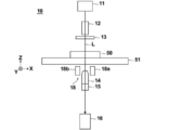
- FIG. 1 is a block diagram showing a schematic configuration of a microscope apparatus 10 in the microscope observation system of the present embodiment.
- the microscope apparatus 10 captures a phase difference image of cultured cells that are observation targets.
- the microscope apparatus 10 includes a white light source 11 that emits white light, a condenser lens 12, a slit plate 13, an imaging optical system 14, and an imaging optical system drive unit. 15, an image sensor 16, and a detection unit 18.
- the slit plate 13 is provided with a ring-shaped slit that transmits white light to the light-shielding plate that blocks white light emitted from the white light source 11, and the ring shape is obtained when white light passes through the slit. Illumination light L is formed.
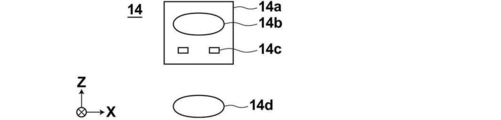
- FIG. 2 is a diagram showing a detailed configuration of the imaging optical system 14.
- the imaging optical system 14 includes a phase difference lens 14a and an imaging lens 14d.
- the phase difference lens 14a includes an objective lens 14b and a phase plate 14c.
- the phase plate 14 c is formed by forming a phase ring on a transparent plate that is transparent with respect to the wavelength of the illumination light L.
- the slit size of the slit plate 13 described above is in a conjugate relationship with the phase ring of the phase plate 14c.
- the phase ring is a ring in which a phase film that shifts the phase of incident light by a quarter wavelength and a neutral density filter that attenuates incident light are formed.
- the phase ring passes through the phase ring, the phase is shifted by 1 ⁇ 4 wavelength, and the brightness is weakened.
- most of the diffracted light diffracted by the observation object passes through the transparent plate of the phase plate 14c, and its phase and brightness do not change.
- the phase difference lens 14a having the objective lens 14b is moved in the optical axis direction of the objective lens 14b by the imaging optical system driving unit 15 shown in FIG.
- the objective lens 14b, the optical axis direction, and the Z direction are the same direction.
- the autofocus control is performed by the movement of the phase difference lens 14a in the Z direction, and the contrast of the phase difference image captured by the image sensor 16 is adjusted.
- the magnification of the phase difference lens 14a may be changed.
- the phase difference lens 14a or the imaging optical system 14 having different magnifications may be configured to be exchangeable. The exchange of the phase difference lens 14a or the imaging optical system 14 may be performed automatically or manually by the user.
- the imaging optical system driving unit 15 includes an actuator such as a piezoelectric element, and is driven based on a control signal output from the imaging optical system control unit 21 described later.
- the imaging optical system drive unit 15 is configured to pass the phase difference image that has passed through the phase difference lens 14a as it is.
- the configuration of the imaging optical system drive unit 15 is not limited to a piezoelectric element, and any other configuration that can move the phase difference lens 14a in the Z direction may be used.
- the imaging lens 14 d receives the phase difference image that has passed through the phase difference lens 14 a and the imaging optical system driving unit 15, and forms an image on the image sensor 16.
- the imaging device 16 captures the phase difference image formed by the imaging lens 14d.
- a CCD (Charge-Coupled Device) image sensor or a CMOS (Complementary Metal-Oxide Semiconductor) image sensor is used.
- CMOS Complementary Metal-Oxide Semiconductor
- an image sensor provided with RGB (Red Green Blue) color filters may be used, or a monochrome image sensor may be used.
- the detection unit 18 detects the position of the culture vessel 50 installed on the stage 51 in the Z direction (vertical direction).
- the detection unit 18 includes a first displacement sensor 18a and a second displacement sensor 18b.
- the first displacement sensor 18a and the second displacement sensor 18b are arranged side by side in the X direction shown in FIG. 1 with the phase difference lens 14a interposed therebetween.
- the first displacement sensor 18a and the second displacement sensor 18b in this embodiment are laser displacement meters, which irradiate the culture vessel 50 with laser light and detect the reflected light, thereby detecting Z on the bottom surface of the culture vessel 50. Detect the position of the direction.
- the bottom surface of the culture vessel 50 is a boundary surface between the bottom portion of the culture vessel 50 and the cell to be observed, that is, the observation target installation surface.
- the position information in the Z direction of the culture vessel 50 detected by the detection unit 18 is output to the imaging optical system control unit 21, and the imaging optical system control unit 21 performs imaging optics based on the input position information.
- the system drive unit 15 is controlled to perform autofocus control. The detection of the position of the culture vessel 50 by the first displacement sensor 18a and the second displacement sensor 18b and the auto-autofocus control by the imaging optical system control unit 21 will be described in detail later.
- a stage 51 is provided between the slit plate 13, the phase difference lens 14 a and the detection unit 18. On the stage 51, a culture vessel 50 in which cells to be observed are accommodated is installed.
- the culture vessel 50 a petri dish, a dish, a well plate, or the like can be used.
- the cells contained in the culture vessel 50 include pluripotent stem cells such as iPS cells and ES cells, nerves, skin, myocardium and liver cells induced to differentiate from the stem cells, and skin, retina extracted from the human body, Examples include heart muscle, blood cells, nerve and organ cells.
- the stage 51 is moved in the X and Y directions orthogonal to each other by a horizontal driving unit 17 (see FIG. 4) described later.
- the X direction and the Y direction are directions orthogonal to the Z direction, and are directions orthogonal to each other in the horizontal plane.
- the X direction is the main scanning direction
- the Y direction is the sub-scanning direction.
- FIG. 3 is a diagram illustrating an example of the stage 51.
- a rectangular opening 51a is formed.
- the culture vessel 50 is installed on the member forming the opening 51a, and the phase difference image of the cells in the culture vessel 50 is configured to pass through the opening 51a.
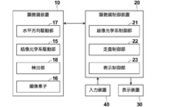
- FIG. 4 is a block diagram showing the configuration of the microscope observation system of the present embodiment.
- the block diagram of the one part structure controlled by each part of the microscope control apparatus 20 is shown.
- the microscope control device 20 controls the entire microscope device 10, and particularly includes an imaging optical system control unit 21, a scanning control unit 22, and a display control unit 23.
- the microscope control device 20 is composed of a computer including a central processing unit, a semiconductor memory, a hard disk, and the like, and an embodiment of the observation device control program of the present invention is installed on the hard disk. Then, when the observation apparatus control program is executed by the central processing unit, the imaging optical system control unit 21, the scanning control unit 22, and the display control unit 23 shown in FIG. 4 function.
- the imaging optical system control unit 21 controls the imaging optical system driving unit 15 based on the position information in the Z direction of the culture vessel 50 detected by the detection unit 18 as described above. Then, the objective lens 14b of the imaging optical system 14 is moved in the optical axis direction by driving the imaging optical system driving unit 15, and autofocus control is performed.
- the scanning control unit 22 drives and controls the horizontal direction driving unit 17, thereby moving the stage 51 in the X direction and the Y direction.
- the horizontal direction drive part 17 is comprised from the actuator which has a piezoelectric element etc.
- FIG. 5 is a diagram showing the scanning position of the observation area in the culture vessel 50 by a solid line M.
- a well plate having six wells W is used as the culture vessel 50.
- the observation area of the imaging optical system 14 moves along the solid line M from the scanning start point S to the scanning end point E. That is, the observation area is scanned in the positive X direction (rightward in FIG. 5), then moved in the Y direction (downward in FIG. 5), and scanned in the opposite negative direction (leftward in FIG. 5). Is done. The observation area then moves again in the Y direction and is scanned again in the positive direction. In this way, the observation area is scanned two-dimensionally in the culture vessel 50 by repeatedly performing reciprocal movement in the X direction and movement in the Y direction.
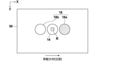
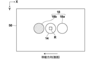
- FIGS. 6 and 7 show the positions of the imaging optical system 14, the first displacement sensor 18 a and the second displacement sensor 18 b, and the culture vessel 50 when the observation region R is at an arbitrary position in the culture vessel 50. It is the figure which showed the relationship.
- a first displacement sensor 18a and a second displacement sensor 18b are provided side by side in the X direction with the imaging optical system 14 interposed therebetween.
- the observation region R of the imaging optical system 14 is scanned two-dimensionally within the culture vessel 50 as described above. At this time, from the position of the observation region R of the imaging optical system 14 with respect to the culture vessel 50 In addition, the position of the culture vessel 50 in the Z direction is detected at the position in front of the observation area R in the moving direction. Specifically, when the observation area R moves in the direction of the arrow shown in FIG. 6 (the right direction in FIG. 6), the observation area R out of the first displacement sensor 18a and the second displacement sensor 18b.
- the position of the culture vessel 50 in the Z direction is detected by the first displacement sensor 18a on the front side in the R movement direction. Then, when the observation area R moves from the position shown in FIG. 6 to the position of the first displacement sensor 18a, autofocus control is performed using the previously detected position information of the culture vessel 50 in the Z direction. Then, a phase difference image is captured.
- the imaging optical system control unit 21 controls the imaging optical system drive unit 15 based on the position information in the Z direction of the culture vessel 50 detected in advance as described above, thereby performing autofocus. Take control. Specifically, in the imaging optical system control unit 21, the relationship between the position information of the culture vessel 50 in the Z direction and the amount of movement of the imaging optical system 14 in the optical axis direction is set in advance. The imaging optical system control unit 21 obtains the movement amount of the imaging optical system 14 in the optical axis direction based on the input position information of the culture vessel 50 in the Z direction, and concludes a control signal corresponding to the movement amount. The image is output to the image optical system driving unit 15. The imaging optical system drive unit 15 is driven based on the input control signal, whereby the imaging optical system 14 (objective lens 14b) moves in the optical axis direction, and corresponds to the position of the culture vessel 50 in the Z direction. Focus adjustment is performed.
- the detection timing of the position of the culture vessel 50 in each observation region R and the phase difference image The imaging timing is shifted in time. Therefore, the movement of the imaging optical system 14 (objective lens 14b) in the Z direction, that is, the autofocus control is performed after the position of the culture vessel 50 is detected by the first displacement sensor 18a or the second displacement sensor 18b. This is performed until the observation area R reaches the detection position.
- the position of the culture vessel 50 in the Z direction may be shifted due to some factor after the autofocus control until the observation area R reaches the detection position. There is a possibility that the focus position shifts.
- the autofocus control timing is just before the observation area R reaches the detection position, and the timing is sufficient to capture the phase difference image at the detection position.
- the observation area R sequentially moves in the X direction, and the detection position by the detection unit 18 is the position of Pd indicated by diagonal lines.
- the observation area R is from the time when it passes through the position Pr of the observation area R adjacent to the detection position Pd to the time when it reaches the detection position Pd.
- the autofocus control may be performed when the observation area R reaches the detection position Pd.
- the autofocus using the position information of the detection position from the detection timing by the first or second displacement sensor 18a and 18b so that the autofocus control timing becomes a desirable timing as described above.
- the time until the control timing is set in advance.
- the preset time is changed in accordance with the changing of the moving speed of the stage 51. Also good.
- the first displacement sensor 18a is moved by moving the first displacement sensor 18a or the second displacement sensor 18b in the X direction.
- the distance between the second displacement sensor 18b and the imaging optical system 14 may be changed.
- the first displacement sensor 18a and the second displacement sensor 18b are provided side by side in the X direction with the imaging optical system 14 interposed therebetween, and the culture vessel 50 is provided prior to the imaging of the phase difference image.
- the imaging optical system 14 In the case of detecting the position, in order to detect the position of the culture vessel 50 and capture the phase difference image in the entire range of the culture vessel 50, as shown in FIG. It is necessary to relatively move the imaging optical system 14, the first displacement sensor 18a, and the second displacement sensor 18b to the ranges R1 and R2.
- the width in the X direction of the range R1 is desirably the distance in the X direction between the first displacement sensor 18a and the imaging optical system 14, and the width in the X direction of the range R2 is the second displacement sensor 18b. It is desirable that the distance between the image forming optical system 14 and the imaging optical system 14 is X.
- the stage 51 when the observation region R is scanned in the range of the culture vessel 50 by moving the stage 51 in the X direction, it is desirable that the moving speed of the observation region R in the range of the culture vessel 50 is constant. Therefore, when the stage 51 starts to move in the X direction, it is necessary to accelerate until the stage 51 reaches a constant speed, and when the stage 51 finishes moving in the X direction, the stage 51 is decelerated from the constant speed and stopped. There is a need.
- the moving speed of the stage 51 in the X direction is set to a constant speed, it is possible to control the speed rapidly to a constant speed with almost no acceleration region, but when such control is performed, The liquid level of the culture solution or the like stored together with the cells in the culture vessel 50 may be shaken, leading to a decrease in the image quality of the phase difference image.
- a similar problem may occur when the stage 51 is stopped.
- the range R1 and the range R2 shown in FIG. 5 are set as the acceleration / deceleration range of the movement of the stage 51 in the X direction.
- the observation area R is scanned at a constant speed in the range of the culture container 50 without unnecessarily widening the scanning range. Can do.
- the shaking of the liquid level of the culture solution as described above can also be suppressed.
- the display control unit 23 generates a single composite phase difference image by combining the phase difference images of each observation region R imaged by the microscope apparatus 10, and the composite phase difference is generated.
- the image is displayed on the display device 30.
- the display device 30 displays the composite phase difference image generated by the display control unit 23 as described above, and includes, for example, a liquid crystal display. Further, the display device 30 may be configured by a touch panel and may also be used as the input device 40.
- the input device 40 includes a mouse and a keyboard, and accepts various setting inputs by the user.
- the input device 40 according to the present embodiment receives setting inputs such as an instruction to change the magnification of the phase difference lens 14a and an instruction to change the moving speed of the stage.
- the culture vessel 50 in which cells to be observed are accommodated is placed on the stage 51 (S10).
- the stage 51 moves, the observation area R of the imaging optical system 14 is set to the position of the scanning start point S shown in FIG. 5, and scanning of the observation area R is started (S12).
- the position of the culture vessel 50 is detected in advance for each observation area R, and when the observation area R reaches the detection position, a phase difference image is captured. Is done. Then, the position detection of the culture vessel 50 and the imaging of the phase difference image are performed while scanning the observation area R, and the phase difference image of the observation area R at a certain position and the front side of the scanning direction from the position are scanned. The position detection of the culture vessel 50 at the position is performed in parallel.
- the imaging optical system control unit 21 calculates the amount of movement of the imaging optical system 14 (objective lens 14b) in the Z direction based on the acquired position information of the culture vessel 50 in the Z direction (S16), and the movement thereof. The amount is stored together with the position on the XY coordinate of the detection position of the culture vessel 50 (S18).
- the observation area R moves toward the position where the position of the culture vessel 50 is detected by the first displacement sensor 18a in S18 (S20).
- the imaging optical system control unit 21 reads the movement amount immediately before the observation region R reaches the position where the position of the culture vessel 50 is detected, and performs autofocus control based on the movement amount (S22, S22). S24). That is, the imaging optical system control unit 21 drives and controls the imaging optical system driving unit 15 based on the movement amount stored in advance, and moves the imaging optical system 14 in the Z direction. Then, after the autofocus control, a phase difference image is taken when the observation region R reaches the position where the position of the culture vessel 50 is detected (S26).
- the phase difference image in the observation area R is output from the image sensor 16 to the display control unit 23 and stored. As described above, while the phase difference image in the observation area R is being captured in S26, the position detection of the culture vessel 50 is performed in parallel at the position in front of the observation area R in the scanning direction. .
- the displacement sensor to be used is switched from the first displacement sensor 18a to the second displacement sensor 18b (S30).
- the displacement sensor to be used is switched every time the observation area R moves to the acceleration / deceleration area R1 and R2, and the processes from S14 to S26 are repeated until all the scans are completed. Then, when the observation area R reaches the position of the scanning end point E shown in FIG. 5, all scanning is completed (S32, YES).
- the display control unit 23 combines the phase difference images of each observation region R to generate a combined phase difference image (S34), and displays the generated combined phase difference image on the display device 30. (S36).
- FIG. 10 is a diagram illustrating a schematic configuration of the microscope observation system according to the second embodiment.
- the microscope observation system of the second embodiment differs from the microscope observation system of the first embodiment in the configuration of the detection unit. Since the other configuration of the microscope observation system according to the second embodiment is the same as that of the first embodiment, the configuration of the detection unit of the microscope observation system according to the second embodiment will be mainly described below.
- the detection unit 18 of the first embodiment includes two displacement sensors, and the displacement unit to be used is switched according to the change in the moving direction of the observation area R.
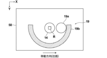
- the detection unit 19 of the second embodiment One displacement sensor is provided, and the position of the displacement sensor is switched according to the change in the moving direction of the observation area R.
- the detection unit 19 includes a displacement sensor 19a and a guide mechanism 19b that guides the displacement sensor 19a and moves the position thereof.
- the displacement sensor 19a is the same as the first and second displacement sensors 18a and 18b of the first embodiment, and includes a laser displacement sensor.
- the guide mechanism 19b includes a semicircular arc guide member, and moves the displacement sensor 19a along the guide member.
- the guide member moves the displacement sensor 19a from one side to the other side in the X direction across the imaging optical system 14 (objective lens 14b).
- FIG. 11 is a diagram showing the position of the displacement sensor 19a when the moving direction of the observation area R is the arrow direction in FIG. 11 (the right direction in FIG. 11).
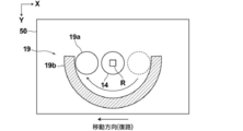
- FIG. 12 is a diagram showing the position of the displacement sensor 19a when the moving direction of the observation area R is the arrow direction in FIG. 12 (left direction in FIG. 12).
- the above-described guide mechanism 19b is provided as a displacement sensor moving mechanism for moving the position of the displacement sensor.
- the configuration of the displacement sensor moving mechanism is not limited to this, and the position of the displacement sensor is determined. Other configurations may be used as long as the configurations can be similarly changed.
- the detection units 18 and 19 detect the position of the culture vessel 50 in the Z direction and perform autofocus control using the detection information. For example, when the bottom of the culture vessel 50 is installed so as to float from the installation surface of the stage 51 or when the bottom of the culture vessel 50 is thick, the distance between the imaging optical system 14 and the bottom of the culture vessel 50 becomes large. Even when the imaging optical system drive unit 15 moves the imaging optical system 14 to the maximum in the Z direction, the position of the bottom surface of the culture vessel 50 does not fall within the range of the depth of field of the imaging optical system 14. There is a case.
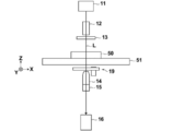
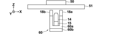
- the imaging optical system 14, the imaging optical system drive unit 15, the first displacement sensor 18a, and the second displacement sensor 18b are integrally formed in the Z direction. It is desirable to provide a vertical direction moving mechanism 60 for moving to the right.
- the vertical movement mechanism 60 includes a holding unit 60a that integrally holds the imaging optical system 14, the imaging optical system driving unit 15, the first displacement sensor 18a, and the second displacement sensor 18b, and the holding unit 60a as Z. And a Z-direction drive unit 60b that moves in the direction.
- the holding unit 60a holds the image forming optical system 14, the image forming optical system driving unit 15, the first displacement sensor 18a, and the second displacement sensor 18b while maintaining the relative positional relationship therebetween.
- the Z direction drive unit 60b includes an actuator such as a piezoelectric element.
- the vertical movement mechanism 60 is configured to pass the phase difference image formed by the imaging optical system 14 as it is.
- the imaging optical system 14, the imaging optical system driving unit 15, the first displacement sensor 18a, and the second displacement sensor 18b are moved using the vertical direction moving mechanism 60. By moving in the Z direction integrally, calibration of autofocus control is performed.
- the calibration first sets the position of the imaging optical system 14 in the Z direction as a reference position by driving the imaging optical system drive unit 15.
- This reference position is a reference position in the above-described autofocus control, and is the center position of the moving range of the imaging optical system 14 in the Z direction.
- the image formed by the imaging optical system 14 at each position is detected by the imaging element 16, and a phase difference image at each position is acquired. .
- a position where the contrast of the phase difference image is maximized is detected.
- the position where the contrast of the phase difference image becomes maximum for example, when the holding unit 60a is sequentially moved upward in the vertical direction, the position where the phase difference image is out of focus and the holding unit 60a are sequentially moved downward in the vertical direction. In this case, the position where the phase difference image is out of focus may be detected, and the center position of these detection positions may be detected as the position where the contrast of the phase difference image is maximized.
- the position where the contrast of the phase difference image is maximized is set as the reference position of the vertical movement mechanism 60, and the calibration is completed.
- the calibration may be performed at the center of gravity of the bottom of the culture vessel 50, for example, but may be performed at a plurality of locations on the bottom of the culture vessel 50. In that case, the average of the reference positions respectively detected at the plurality of locations may be set as the final reference position.
- FIG. 13 is a diagram illustrating an example in which a vertical movement mechanism 61 is provided in the microscope observation system of the second embodiment.
- the vertical movement mechanism 61 includes a holding unit 61a that integrally holds the imaging optical system 14, the imaging optical system driving unit 15, and the detection unit 19, and a Z-direction driving unit 61b that moves the holding unit 61a in the Z direction. It has.
- the holding unit 61 a holds the image forming optical system 14, the image forming optical system driving unit 15, and the displacement sensor 19 a of the detecting unit 19 while maintaining the relative positional relationship therebetween.
- the Z-direction drive unit 61b includes an actuator such as a piezoelectric element, for example, similarly to the Z-direction drive unit 60b described above.
- the calibration method is the same as in the case of the microscope observation system of the first embodiment described above.
- the observation area R is scanned by moving the stage 51.
- the present invention is not limited to this, and the stage 51 is fixed, and the imaging optical system 14 and other phase difference images are captured.
- the observation area R may be scanned by moving the configuration related to the observation area, or the observation area R may be moved by moving both the stage 51 and the imaging optical system 14 and other configurations related to imaging of the phase difference image. R may be scanned.
- the present invention is applied to a phase contrast microscope.
- the present invention is not limited to the phase contrast microscope, and is applied to other microscopes such as a differential interference microscope and a bright field microscope. Also good.
- the phase difference image formed by the image forming optical system 14 is picked up by the image pickup device 16, but the image is formed by the image forming optical system 14 without providing the image pickup device.
- An observation optical system or the like may be provided so that the user can directly observe the phase difference image of the observation target.
Abstract
Provided is an observation device and method as well as an observation control program with which the speed of autofocus control in each observation area can be increased and the scanning time in each observation area can be reduced. The present invention comprises: a stage 51; an imaging optical system 14 including an objective lens; a detection unit 18 including displacement sensors 18a, 18b that detect the position in the vertical direction of a culture container 50; an imaging optical system control unit 21 that controls an imaging optical system drive unit 15 on the basis of the vertical direction position of the culture container 50 to move the objective lens in the optical axis direction; and a horizontal direction drive unit 17 that moves the stage 51 in a main scanning direction and a sub scanning direction and that reciprocally moves the stage 51 in the main scanning direction. The detection unit 18 detects the vertical direction position of the culture container 50 at a position in the observation area more toward the front side in the movement direction than the position in the observation area of the imaging optical system 14 relative to the culture container 50, and switches the displacement sensor to be used according to changes in the movement direction in the main scanning direction.
Description
本発明は、観察対象が収容された容器が設置されたステージと観察対象の像を結像させる結像光学系とを相対的に移動させることによって、観察対象全体の像を観察する観察装置および方法並びに観察装置制御プログラムに関する。
The present invention relates to an observation apparatus for observing an image of an entire observation object by relatively moving a stage on which a container in which the observation object is accommodated and an imaging optical system for forming an image of the observation object. The present invention relates to a method and an observation apparatus control program.
従来、ES(Embryonic Stem)細胞およびiPS(Induced Pluripotent Stem)細胞などの多能性幹細胞や分化誘導された細胞などを顕微鏡などで撮像し、その画像の特徴を捉えることによって細胞の分化状態などを判定する方法が提案されている。
Conventionally, pluripotent stem cells such as ES (Embryonic Stem) cells and iPS (Induced uri Pluripotent Stem) cells and differentiation-induced cells are imaged with a microscope, etc., and the differentiation state of the cells is captured by capturing the characteristics of the images A determination method has been proposed.
ES細胞およびiPS細胞などの多能性幹細胞は、種々の組織の細胞に分化する能力を備えたものであり、再生医療、薬の開発、および病気の解明などにおいて応用が可能なものとして注目されている。
Pluripotent stem cells such as ES cells and iPS cells have the ability to differentiate into cells of various tissues, and are attracting attention as being applicable in regenerative medicine, drug development, and disease elucidation. ing.
一方、上述したように細胞を顕微鏡で撮像する際、高倍率な広視野画像を取得するため、たとえばウェルプレートなどの培養容器の範囲内を結像光学系の観察域によって走査し、観察域毎の画像を撮像した後、その観察域毎の画像を結合する、いわゆるタイリング撮影を行うことが提案されている。
On the other hand, as described above, when a cell is imaged with a microscope, in order to obtain a high-power wide-field image, for example, the inside of a culture vessel such as a well plate is scanned by the observation area of the imaging optical system. It has been proposed to perform so-called tiling photography in which images for each observation area are combined after the above images are taken.
ここで、上述したような観察域毎の画像を撮像する際、培養容器の底面に結像光学系の焦点位置を合わせることが多いが、培養容器の底部の厚さには、ミリオーダーでの製造公差があり、高倍率な撮影を行う場合には、観察域毎に焦点位置を合わせる必要がある。一方、細胞の撮影時間は短い方が望ましく、高速撮影可能な装置が望まれている。
Here, when taking an image for each observation region as described above, the focal position of the imaging optical system is often adjusted to the bottom surface of the culture vessel, but the thickness of the bottom portion of the culture vessel is in the order of millimeters. When there is a manufacturing tolerance and high-magnification imaging is performed, it is necessary to adjust the focal position for each observation area. On the other hand, it is desirable that the cell imaging time is short, and an apparatus capable of high-speed imaging is desired.
しかし、従来のオートフォーカス制御方法では、観察域毎に2秒程度の時間を要し、たとえば観察域の数が300である場合には、オートフォーカス制御に要する時間だけで100分かかることになり、高速撮影が不可能であった。
However, in the conventional autofocus control method, it takes about 2 seconds for each observation region. For example, when the number of observation regions is 300, only the time required for autofocus control takes 100 minutes. High-speed shooting was impossible.
特許文献1においては、撮影時間を短縮するため、ある観察域の画像を撮像している時点において、その観察域に隣接する領域で焦点位置を先行して計測しておき、その前持って計測された焦点位置を用いてフォーカス制御を行って画像の撮像を行う方法が提案されている。
In Patent Document 1, in order to shorten the photographing time, at the time when an image of a certain observation area is captured, the focal position is measured in advance in an area adjacent to the observation area, and the measurement is performed before that. A method has been proposed in which an image is captured by performing focus control using the focused position.
しかし、特許文献1においては、焦点位置を計測する際、やはり従来のオートフォーカス制御の場合と同様に、上記観察域に隣接する領域の画像を撮像し、その画像のコントラストに基づいて焦点位置を計測しているため、演算処理に時間がかかってしまう。したがって、ステージを高速に移動させた場合には、観察域が計測位置に到達した時点において演算処理およびその演算処理結果に基づくオートフォーカス制御が間に合わない可能性がある。
However, in Patent Document 1, when measuring the focal position, as in the case of conventional autofocus control, an image of an area adjacent to the observation area is captured, and the focal position is determined based on the contrast of the image. Since it is measuring, it takes time for the arithmetic processing. Therefore, when the stage is moved at a high speed, there is a possibility that the calculation process and autofocus control based on the calculation process result will not be in time when the observation area reaches the measurement position.
また、特許文献1では、観察域を一方向のみに走査する方法しか提案されておらず、このように一方向のみの走査では、走査時間が非常に長くなってしまう。
Further, in Patent Document 1, only a method of scanning the observation area in only one direction is proposed, and in such a scanning in only one direction, the scanning time becomes very long.
本発明は、上記の問題に鑑み、観察域毎のオートフォーカス制御を高速化することができ、これにより全ての範囲の観察域の走査時間を短縮することができる観察装置および方法並びに観察制御プログラムを提供することを目的とする。
In view of the above-described problems, the present invention can increase the speed of autofocus control for each observation area, thereby shortening the scanning time of the observation area in all ranges, and an observation control program. The purpose is to provide.
本発明の観察装置は、観察対象が収容された容器が設置されるステージと、容器内の観察対象の像を結像させる対物レンズを有する結像光学系と、対物レンズを光軸方向に移動させる結像光学系駆動部と、ステージに設置された容器の鉛直方向の位置を検出する少なくとも1つの変位センサを有する検出部と、検出部によって検出された容器の鉛直方向の位置に基づいて、結像光学系駆動部を制御する結像光学系制御部と、ステージおよび結像光学系の少なくとも一方を、水平面内の主走査方向および主走査方向に直交する副走査方向に移動させ、かつ上記少なくとも一方を主走査方向について往復移動させる水平方向駆動部と、水平方向駆動部を制御する走査制御部とを備え、検出部が、容器に対する結像光学系の観察域の位置よりも観察域の移動方向前側の位置において容器の鉛直方向の位置を検出し、かつ主走査方向の移動方向の変更に応じて、変位センサの主走査方向の位置または使用する変位センサを切り替える。
An observation apparatus according to the present invention includes a stage on which a container in which an observation target is stored is installed, an imaging optical system having an objective lens that forms an image of the observation target in the container, and the objective lens is moved in the optical axis direction. Based on the vertical position of the container detected by the detection unit, an imaging optical system driving unit to be detected, a detection unit having at least one displacement sensor for detecting the vertical position of the container installed on the stage, An imaging optical system control unit that controls the imaging optical system driving unit, and at least one of the stage and the imaging optical system is moved in a main scanning direction in a horizontal plane and in a sub-scanning direction perpendicular to the main scanning direction, and A horizontal direction drive unit that reciprocates at least one of the main scan directions; and a scan control unit that controls the horizontal direction drive unit, wherein the detection unit is positioned more than the position of the observation area of the imaging optical system with respect to the container. Detecting a vertical position of the container at the position of the moving direction front range, and in accordance with a change in the moving direction of the main scanning direction, switches the displacement sensors located or used in the main scanning direction of the displacement sensor.
また、上記本発明の観察装置において、検出部は、対物レンズを挟んで主走査方向について並べて設けられた少なくとも2つの変位センサを有し、主走査方向の移動方向の変更に応じて、使用する変位センサを切り替えることができる。
In the observation apparatus of the present invention, the detection unit includes at least two displacement sensors arranged in the main scanning direction with the objective lens interposed therebetween, and is used according to a change in the movement direction in the main scanning direction. The displacement sensor can be switched.
また、上記本発明の観察装置において、検出部は、対物レンズを挟んで主走査方向について一方の側と他方の側とに変位センサを移動可能な変位センサ移動機構を有し、主走査方向の移動方向の変更に応じて、変位センサの位置を上記一方の側から上記他方の側に移動することができる。
In the observation apparatus of the present invention, the detection unit includes a displacement sensor moving mechanism that can move the displacement sensor to one side and the other side in the main scanning direction with the objective lens interposed therebetween. In accordance with the change of the moving direction, the position of the displacement sensor can be moved from the one side to the other side.
また、上記本発明の観察装置において、変位センサ移動機構は、変位センサを上記一方の側から上記他方の側まで案内するガイド機構を備えることができる。
In the observation apparatus of the present invention, the displacement sensor moving mechanism may include a guide mechanism that guides the displacement sensor from the one side to the other side.
また、上記本発明の観察装置において、結像光学系制御部は、検出部によって容器の鉛直方向の位置が検出された後、予め設定された時間が経過した時点において結像光学系駆動部を制御して対物レンズを光軸方向に移動させることができる。
In the observation apparatus according to the present invention, the imaging optical system control unit moves the imaging optical system drive unit when a preset time has elapsed after the detection unit detects the vertical position of the container. The objective lens can be moved in the optical axis direction by control.
また、上記本発明の観察装置において、結像光学系制御部は、検出部によって容器の鉛直方向の位置が検出された後、その検出位置に結像光学系の観察域が到達した時点または検出位置に結像光学系の観察域が到達する直前において結像光学系駆動部を制御して対物レンズを光軸方向に移動させることができる。
In the observation apparatus of the present invention described above, the imaging optical system control unit detects or detects when the observation region of the imaging optical system reaches the detection position after the detection unit detects the vertical position of the container. The objective lens can be moved in the optical axis direction by controlling the imaging optical system drive unit immediately before the observation area of the imaging optical system reaches the position.
また、上記本発明の観察装置において、結像光学系制御部は、走査制御部によってステージおよび結像光学系の少なくとも一方の移動速度が変更された場合、その変更後の移動速度に応じて、予め設定された時間を変更することができる。
In the observation apparatus of the present invention, when the moving speed of at least one of the stage and the imaging optical system is changed by the scanning control unit, the imaging optical system control unit, depending on the changed moving speed, The preset time can be changed.
また、上記本発明の観察装置においては、容器の範囲の主走査方向の両側に、ステージおよび結像光学系の少なくとも一方の主走査方向への移動の加減速域を設定し、その加減速域の主走査方向の幅と結像光学系と変位センサとの主走査方向の間隔とを同じにすることが望ましい。
Further, in the observation apparatus of the present invention, an acceleration / deceleration region of movement in the main scanning direction of at least one of the stage and the imaging optical system is set on both sides of the container range in the main scanning direction, and the acceleration / deceleration region is set. It is desirable that the width in the main scanning direction and the interval in the main scanning direction between the imaging optical system and the displacement sensor be the same.
また、上記本発明の観察装置においては、結像光学系、結像光学系駆動部および変位センサを一体的に鉛直方向に移動させる鉛直方向移動機構を備えることができる。
The observation apparatus of the present invention may further include a vertical direction moving mechanism that integrally moves the imaging optical system, the imaging optical system drive unit, and the displacement sensor in the vertical direction.
また、上記本発明の観察装置において、結像光学系駆動部は、圧電素子を備え、その圧電素子を用いて対物レンズを光軸方向に移動させることができる。
In the observation apparatus of the present invention, the imaging optical system drive unit includes a piezoelectric element, and the objective lens can be moved in the optical axis direction using the piezoelectric element.
また、上記本発明の観察装置においては、変位センサとして、レーザ変位センサを用いることができる。
In the observation apparatus of the present invention, a laser displacement sensor can be used as the displacement sensor.
本発明の観察方法は、観察対象が収容された容器が設置されるステージおよび容器内の観察対象の像を結像させる対物レンズを有する結像光学系の少なくとも一方を主走査方向および主走査方向に直交する副走査方向に移動させ、かつ上記少なくとも一方を主走査方向について往復移動させる観察方法において、容器に対する結像光学系の観察域の位置よりも観察域の移動方向前側の位置における容器の鉛直方向の位置を、少なくとも1つの変位センサを用いて検出し、その検出した容器の鉛直方向の位置に基づいて、対物レンズを光軸方向に移動させ、かつ主走査方向の移動方向の変更に応じて、変位センサの主走査方向の位置または使用する変位センサを切り替える。
According to the observation method of the present invention, at least one of a stage on which a container in which an observation object is accommodated and an objective lens that forms an image of the observation object in the container is formed in the main scanning direction and the main scanning direction. In the observation method of moving in the sub-scanning direction orthogonal to the image and reciprocally moving at least one of the above-mentioned in the main scanning direction, the position of the container at a position on the front side in the moving direction of the observation area with respect to the position of the observation area of the imaging optical system with respect to the container The position in the vertical direction is detected using at least one displacement sensor, and the objective lens is moved in the optical axis direction based on the detected position in the vertical direction of the container, and the moving direction in the main scanning direction is changed. In response, the position of the displacement sensor in the main scanning direction or the displacement sensor to be used is switched.
本発明の観察装置制御プログラムは、観察対象が収容された容器が設置されるステージおよび容器内の観察対象の像を結像させる対物レンズを有する結像光学系の少なくとも一方を主走査方向および主走査方向に直交する副走査方向に移動させ、かつ上記少なくとも一方を主走査方向について往復移動させる手順をコンピュータに実行させる観察装置制御プログラムにおいて、容器に対する結像光学系の観察域の位置よりも観察域の移動方向前側の位置における容器の鉛直方向の位置を、少なくとも1つの変位センサを用いて検出する手順と、その検出した容器の鉛直方向の位置に基づいて、対物レンズを光軸方向に移動させる手順と、かつ主走査方向の移動方向の変更に応じて、変位センサの主走査方向の位置または使用する変位センサを切り替える手順とをコンピュータに実行させることを特徴とする。
An observation apparatus control program according to the present invention includes at least one of a stage on which a container in which an observation object is accommodated and an imaging optical system having an objective lens that forms an image of the observation object in the container in the main scanning direction and the main scanning direction. In an observation apparatus control program for causing a computer to execute a procedure for moving in the sub-scanning direction orthogonal to the scanning direction and reciprocating at least one of the above in the main scanning direction, the observation is performed more than the position of the observation area of the imaging optical system relative to the container. The objective lens is moved in the direction of the optical axis based on the procedure of detecting the vertical position of the container at the front position in the moving direction of the area using at least one displacement sensor and the detected vertical position of the container. And the displacement sensor position in the main scanning direction or the displacement sensor to be used according to the change of the moving direction in the main scanning direction. Characterized in that to perform the procedure for switching the computer.
本発明の観察装置および方法並びに観察装置制御プログラムによれば、容器が設置されるステージおよび容器内の観察対象の像を結像させる結像光学系の少なくとも一方を主走査方向および副走査方向に移動させ、かつ上記少なくとも一方を主走査方向について往復移動させる。このように、主走査方向についてステージまたは結像光学系を往復移動させて結像光学系の観察域を走査することによって、上述した特許文献1のような一方向にのみステージを移動させて観察域を走査する場合と比較すると、観察域の走査時間を短縮することができる。
According to the observation apparatus and method and the observation apparatus control program of the present invention, at least one of the stage on which the container is installed and the imaging optical system that forms an image of the observation target in the container is arranged in the main scanning direction and the sub scanning direction. And at least one of them is reciprocated in the main scanning direction. In this way, the stage or the imaging optical system is moved back and forth in the main scanning direction to scan the observation area of the imaging optical system, so that the stage is moved only in one direction as described in Patent Document 1 and observed. Compared to scanning the area, the scanning time of the observation area can be shortened.
さらに、本発明では、容器に対する結像光学系の観察域の位置よりも観察域の移動方向前側の位置における容器の鉛直方向の位置を、少なくとも1つの変位センサを用いて検出し、その検出した容器の鉛直方向の位置に基づいて、対物レンズを光軸方向に移動させることによってオートフォーカス制御を行うようにしたので、特許文献1のように撮像された画像のコントラストに基づいてオートフォーカス制御を行う場合と比較すると、高速にオートフォーカス制御を行うことができる。
Furthermore, in the present invention, the position in the vertical direction of the container at the position on the front side in the moving direction of the observation area relative to the position of the observation area of the imaging optical system with respect to the container is detected using at least one displacement sensor, and the detection is performed. Since the autofocus control is performed by moving the objective lens in the optical axis direction based on the vertical position of the container, the autofocus control is performed based on the contrast of the captured image as in Patent Document 1. Compared with the case where it is performed, the autofocus control can be performed at high speed.
さらに、本発明では、主走査方向の移動方向の変更に応じて、変位センサの主走査方向の位置または使用する変位センサを切り替えるようにしたので、観察域を往復移動させて走査する場合においても、常に、画像の撮像に先行して容器の位置の検出を行うことができる。
Furthermore, in the present invention, the position of the displacement sensor in the main scanning direction or the displacement sensor to be used is switched in accordance with the change in the moving direction in the main scanning direction. The position of the container can always be detected prior to imaging.
以下、本発明の観察装置および方法並びに観察装置制御プログラムの第1の実施形態を用いた顕微鏡観察システムについて、図面を参照しながら詳細に説明する。図1は、本実施形態の顕微鏡観察システムにおける顕微鏡装置10の概略構成を示すブロック図である。
Hereinafter, the microscope observation system using the first embodiment of the observation apparatus and method and the observation apparatus control program of the present invention will be described in detail with reference to the drawings. FIG. 1 is a block diagram showing a schematic configuration of a microscope apparatus 10 in the microscope observation system of the present embodiment.
顕微鏡装置10は、観察対象である培養された細胞の位相差画像を撮像する。具体的には、顕微鏡装置10は、図1に示すように、白色光を出射する白色光源11と、コンデンサレンズ12と、スリット板13と、結像光学系14と、結像光学系駆動部15と、撮像素子16と、検出部18とを備えている。
The microscope apparatus 10 captures a phase difference image of cultured cells that are observation targets. Specifically, as shown in FIG. 1, the microscope apparatus 10 includes a white light source 11 that emits white light, a condenser lens 12, a slit plate 13, an imaging optical system 14, and an imaging optical system drive unit. 15, an image sensor 16, and a detection unit 18.
スリット板13は、白色光源11から出射された白色光を遮光する遮光板に対して白色光を透過するリング形状のスリットが設けられたものであり、白色光がスリットを通過することによってリング状の照明光Lが形成される。
The slit plate 13 is provided with a ring-shaped slit that transmits white light to the light-shielding plate that blocks white light emitted from the white light source 11, and the ring shape is obtained when white light passes through the slit. Illumination light L is formed.
図2は、結像光学系14の詳細な構成を示す図である。結像光学系14は、図2に示すように、位相差レンズ14aおよび結像レンズ14dを備えている。そして、位相差レンズ14aは、対物レンズ14bおよび位相板14cを備えている。位相板14cは、照明光Lの波長に対して透明な透明板に対して位相リングを形成したものである。なお、上述したスリット板13のスリットの大きさは、位相板14cの位相リングと共役な関係にある。
FIG. 2 is a diagram showing a detailed configuration of the imaging optical system 14. As shown in FIG. 2, the imaging optical system 14 includes a phase difference lens 14a and an imaging lens 14d. The phase difference lens 14a includes an objective lens 14b and a phase plate 14c. The phase plate 14 c is formed by forming a phase ring on a transparent plate that is transparent with respect to the wavelength of the illumination light L. The slit size of the slit plate 13 described above is in a conjugate relationship with the phase ring of the phase plate 14c.
位相リングは、入射された光の位相を1/4波長ずらす位相膜と、入射された光を減光する減光フィルタとがリング状に形成されたものである。位相リングに入射された直接光は、位相リングを通過することによって位相が1/4波長ずれ、かつ、その明るさが弱められる。一方、観察対象によって回折された回折光は大部分が位相板14cの透明板を通過し、その位相および明るさは変化しない。
The phase ring is a ring in which a phase film that shifts the phase of incident light by a quarter wavelength and a neutral density filter that attenuates incident light are formed. When the direct light incident on the phase ring passes through the phase ring, the phase is shifted by ¼ wavelength, and the brightness is weakened. On the other hand, most of the diffracted light diffracted by the observation object passes through the transparent plate of the phase plate 14c, and its phase and brightness do not change.
対物レンズ14bを有する位相差レンズ14aは、図1に示す結像光学系駆動部15によって対物レンズ14bの光軸方向に移動する。なお、本実施形態においては、対物レンズ14bと光軸方向とZ方向(鉛直方向)とは同じ方向である。位相差レンズ14aのZ方向への移動によってオートフォーカス制御が行われ、撮像素子16によって撮像される位相差画像のコントラストが調整される。
The phase difference lens 14a having the objective lens 14b is moved in the optical axis direction of the objective lens 14b by the imaging optical system driving unit 15 shown in FIG. In the present embodiment, the objective lens 14b, the optical axis direction, and the Z direction (vertical direction) are the same direction. The autofocus control is performed by the movement of the phase difference lens 14a in the Z direction, and the contrast of the phase difference image captured by the image sensor 16 is adjusted.
また、位相差レンズ14aの倍率を変更可能な構成としてもよい。具体的には、異なる倍率を有する位相差レンズ14aまたは結像光学系14を交換可能に構成するようにしてもよい。位相差レンズ14aまたは結像光学系14の交換は、自動的に行うようにしてもよいし、ユーザが手動にて行うようにしてもよい。
Further, the magnification of the phase difference lens 14a may be changed. Specifically, the phase difference lens 14a or the imaging optical system 14 having different magnifications may be configured to be exchangeable. The exchange of the phase difference lens 14a or the imaging optical system 14 may be performed automatically or manually by the user.
結像光学系駆動部15は、たとえば圧電素子のようなアクチュエータを備え、後述する結像光学系制御部21から出力された制御信号に基づいて駆動する。なお、結像光学系駆動部15は、位相差レンズ14aを通過した位相差画像をそのまま通過させる構成となっている。また、結像光学系駆動部15の構成は圧電素子に限らず、位相差レンズ14aをZ方向に移動可能なものであればよく、その他の公知な構成を用いることができる。
The imaging optical system driving unit 15 includes an actuator such as a piezoelectric element, and is driven based on a control signal output from the imaging optical system control unit 21 described later. The imaging optical system drive unit 15 is configured to pass the phase difference image that has passed through the phase difference lens 14a as it is. The configuration of the imaging optical system drive unit 15 is not limited to a piezoelectric element, and any other configuration that can move the phase difference lens 14a in the Z direction may be used.
結像レンズ14dは、位相差レンズ14aおよび結像光学系駆動部15を通過した位相差画像が入射され、これを撮像素子16に結像する。
The imaging lens 14 d receives the phase difference image that has passed through the phase difference lens 14 a and the imaging optical system driving unit 15, and forms an image on the image sensor 16.
撮像素子16は、結像レンズ14dによって結像された位相差画像を撮像する。撮像素子16としては、CCD(Charge-Coupled Device)イメージセンサまたはCMOS(Complementary Metal-Oxide Semiconductor)イメージセンサなどが用いられる。撮像素子としては、RGB(Red Green Blue)のカラーフィルタが設けられた撮像素子を用いてもよいし、モノクロの撮像素子を用いるようにしてもよい。
The imaging device 16 captures the phase difference image formed by the imaging lens 14d. As the imaging element 16, a CCD (Charge-Coupled Device) image sensor or a CMOS (Complementary Metal-Oxide Semiconductor) image sensor is used. As the image sensor, an image sensor provided with RGB (Red Green Blue) color filters may be used, or a monochrome image sensor may be used.
検出部18は、ステージ51に設置された培養容器50のZ方向(鉛直方向)の位置を検出する。検出部18は、具体的には、第1の変位センサ18aおよび第2の変位センサ18bを備えている。第1の変位センサ18aおよび第2の変位センサ18bは、位相差レンズ14aを挟んで、図1に示すX方向に並べて設けられている。本実施形態における第1の変位センサ18aおよび第2の変位センサ18bはレーザ変位計であり、培養容器50にレーザ光を照射し、その反射光を検出することによって、培養容器50の底面のZ方向の位置を検出する。なお、培養容器50の底面とは、培養容器50の底部と観察対象である細胞との境界面であり、すなわち観察対象設置面である。
The detection unit 18 detects the position of the culture vessel 50 installed on the stage 51 in the Z direction (vertical direction). Specifically, the detection unit 18 includes a first displacement sensor 18a and a second displacement sensor 18b. The first displacement sensor 18a and the second displacement sensor 18b are arranged side by side in the X direction shown in FIG. 1 with the phase difference lens 14a interposed therebetween. The first displacement sensor 18a and the second displacement sensor 18b in this embodiment are laser displacement meters, which irradiate the culture vessel 50 with laser light and detect the reflected light, thereby detecting Z on the bottom surface of the culture vessel 50. Detect the position of the direction. The bottom surface of the culture vessel 50 is a boundary surface between the bottom portion of the culture vessel 50 and the cell to be observed, that is, the observation target installation surface.
検出部18によって検出された培養容器50のZ方向の位置情報は、結像光学系制御部21に出力され、結像光学系制御部21は、入力された位置情報に基づいて、結像光学系駆動部15を制御し、オートフォーカス制御を行う。なお、第1の変位センサ18aおよび第2の変位センサ18bによる培養容器50の位置の検出および結像光学系制御部21によるオートオートフォーカス制御については、後で詳述する。
The position information in the Z direction of the culture vessel 50 detected by the detection unit 18 is output to the imaging optical system control unit 21, and the imaging optical system control unit 21 performs imaging optics based on the input position information. The system drive unit 15 is controlled to perform autofocus control. The detection of the position of the culture vessel 50 by the first displacement sensor 18a and the second displacement sensor 18b and the auto-autofocus control by the imaging optical system control unit 21 will be described in detail later.
スリット板13と位相差レンズ14aおよび検出部18との間には、ステージ51が設けられている。ステージ51上には、観察対象である細胞が収容された培養容器50が設置される。
A stage 51 is provided between the slit plate 13, the phase difference lens 14 a and the detection unit 18. On the stage 51, a culture vessel 50 in which cells to be observed are accommodated is installed.
培養容器50としては、シャーレ、ディッシュまたはウェルプレートなどを用いることができる。また、培養容器50に収容される細胞としては、iPS細胞およびES細胞といった多能性幹細胞、幹細胞から分化誘導された神経、皮膚、心筋および肝臓の細胞、並びに人体から取り出された皮膚、網膜、心筋、血球、神経および臓器の細胞などがある。
As the culture vessel 50, a petri dish, a dish, a well plate, or the like can be used. The cells contained in the culture vessel 50 include pluripotent stem cells such as iPS cells and ES cells, nerves, skin, myocardium and liver cells induced to differentiate from the stem cells, and skin, retina extracted from the human body, Examples include heart muscle, blood cells, nerve and organ cells.
ステージ51は、後述する水平方向駆動部17(図4参照)によって互いに直交するX方向およびY方向に移動する。X方向およびY方向は、Z方向に直交する方向であり、水平面内において互いに直交する方向である。本実施形態においては、X方向を主走査方向とし、Y方向を副走査方向とする。
The stage 51 is moved in the X and Y directions orthogonal to each other by a horizontal driving unit 17 (see FIG. 4) described later. The X direction and the Y direction are directions orthogonal to the Z direction, and are directions orthogonal to each other in the horizontal plane. In the present embodiment, the X direction is the main scanning direction, and the Y direction is the sub-scanning direction.
図3は、ステージ51の一例を示す図である。ステージ51の中央には、矩形の開口51aが形成されている。この開口51aを形成する部材の上に培養容器50が設置され、培養容器50内の細胞の位相差画像が開口51aを通過するように構成されている。
FIG. 3 is a diagram illustrating an example of the stage 51. In the center of the stage 51, a rectangular opening 51a is formed. The culture vessel 50 is installed on the member forming the opening 51a, and the phase difference image of the cells in the culture vessel 50 is configured to pass through the opening 51a.
次に、顕微鏡装置10を制御する顕微鏡制御装置20の構成について説明する。図4は、本実施形態の顕微鏡観察システムの構成を示すブロック図である。なお、顕微鏡装置10については、顕微鏡制御装置20の各部により制御される一部の構成のブロック図を示している。
Next, the configuration of the microscope control device 20 that controls the microscope device 10 will be described. FIG. 4 is a block diagram showing the configuration of the microscope observation system of the present embodiment. In addition, about the microscope apparatus 10, the block diagram of the one part structure controlled by each part of the microscope control apparatus 20 is shown.
顕微鏡制御装置20は、顕微鏡装置10全体を制御し、特に、結像光学系制御部21、走査制御部22および表示制御部23を備える。
The microscope control device 20 controls the entire microscope device 10, and particularly includes an imaging optical system control unit 21, a scanning control unit 22, and a display control unit 23.
顕微鏡制御装置20は、中央処理装置、半導体メモリおよびハードディスクなどを備えたコンピュータから構成され、ハードディスクに本発明の観察装置制御プログラムの一実施形態がインストールされている。そして、この観察装置制御プログラムが中央処理装置によって実行されることによって、図4に示す結像光学系制御部21、走査制御部22および表示制御部23が機能する。
The microscope control device 20 is composed of a computer including a central processing unit, a semiconductor memory, a hard disk, and the like, and an embodiment of the observation device control program of the present invention is installed on the hard disk. Then, when the observation apparatus control program is executed by the central processing unit, the imaging optical system control unit 21, the scanning control unit 22, and the display control unit 23 shown in FIG. 4 function.
結像光学系制御部21は、上述したように検出部18によって検出された培養容器50のZ方向の位置情報に基づいて、結像光学系駆動部15を制御する。そして、結像光学系駆動部15の駆動によって結像光学系14の対物レンズ14bが光軸方向に移動し、オートフォーカス制御が行われる。
The imaging optical system control unit 21 controls the imaging optical system driving unit 15 based on the position information in the Z direction of the culture vessel 50 detected by the detection unit 18 as described above. Then, the objective lens 14b of the imaging optical system 14 is moved in the optical axis direction by driving the imaging optical system driving unit 15, and autofocus control is performed.
走査制御部22は、水平方向駆動部17を駆動制御し、これによりステージ51をX方向およびY方向に移動させる。水平方向駆動部17は、圧電素子などを有するアクチュエータから構成される。
The scanning control unit 22 drives and controls the horizontal direction driving unit 17, thereby moving the stage 51 in the X direction and the Y direction. The horizontal direction drive part 17 is comprised from the actuator which has a piezoelectric element etc.
以下、走査制御部22によるステージ51の移動制御および結像光学系制御部21によるオートフォーカス制御について、詳細に説明する。
Hereinafter, the movement control of the stage 51 by the scanning control unit 22 and the autofocus control by the imaging optical system control unit 21 will be described in detail.
本実施形態においては、走査制御部22による制御によってステージ51をX方向およびY方向に移動させ、結像光学系14の観察域を培養容器50内において2次元状に走査し、各観察域の位相差画像を撮像する。図5は、培養容器50内における観察域の走査位置を実線Mで示した図である。なお、本実施形態においては、培養容器50として6つのウェルWを有するウェルプレートを用いる。
In the present embodiment, the stage 51 is moved in the X direction and the Y direction by the control by the scanning control unit 22, and the observation area of the imaging optical system 14 is scanned two-dimensionally in the culture vessel 50. A phase difference image is taken. FIG. 5 is a diagram showing the scanning position of the observation area in the culture vessel 50 by a solid line M. In the present embodiment, a well plate having six wells W is used as the culture vessel 50.
図5に示すように、結像光学系14の観察域は、走査開始点Sから走査終了点Eまで実線Mに沿って移動する。すなわち、観察域は、X方向の正方向(図5の右方向)に走査された後、Y方向(図5の下方向)に移動し、逆の負方向(図5の左方向)に走査される。次いで、観察域は、再びY方向に移動し、再び正方向に走査される。このように、観察域は、X方向についての往復移動とY方向への移動を繰り返し行うことによって、培養容器50内を2次元状に走査される。
As shown in FIG. 5, the observation area of the imaging optical system 14 moves along the solid line M from the scanning start point S to the scanning end point E. That is, the observation area is scanned in the positive X direction (rightward in FIG. 5), then moved in the Y direction (downward in FIG. 5), and scanned in the opposite negative direction (leftward in FIG. 5). Is done. The observation area then moves again in the Y direction and is scanned again in the positive direction. In this way, the observation area is scanned two-dimensionally in the culture vessel 50 by repeatedly performing reciprocal movement in the X direction and movement in the Y direction.
図6および図7は、培養容器50内の任意の位置に観察域Rがある場合における結像光学系14、第1の変位センサ18aおよび第2の変位センサ18bと、培養容器50との位置関係を示した図である。
6 and 7 show the positions of the imaging optical system 14, the first displacement sensor 18 a and the second displacement sensor 18 b, and the culture vessel 50 when the observation region R is at an arbitrary position in the culture vessel 50. It is the figure which showed the relationship.
本実施形態においては、図6および図7に示すように、第1の変位センサ18aと第2の変位センサ18bが結像光学系14を挟んでX方向に並べて設けられている。そして、結像光学系14の観察域Rは、上述したように培養容器50内を2次元状に走査されるが、この際、培養容器50に対する結像光学系14の観察域Rの位置よりも観察域Rの移動方向前側の位置において培養容器50のZ方向の位置が検出される。具体的には、観察域Rが、図6に示す矢印方向(図6の右方向)に移動している場合には、第1の変位センサ18aおよび第2の変位センサ18bのうち、観察域Rの移動方向前側の第1の変位センサ18aによって培養容器50のZ方向の位置が検出される。そして、観察域Rが、図6に示す位置から第1の変位センサ18aの位置まで移動した場合に、前もって検出された培養容器50のZ方向の位置情報が用いられてオートフォーカス制御が行われ、位相差画像の撮像が行われる。
In the present embodiment, as shown in FIGS. 6 and 7, a first displacement sensor 18a and a second displacement sensor 18b are provided side by side in the X direction with the imaging optical system 14 interposed therebetween. The observation region R of the imaging optical system 14 is scanned two-dimensionally within the culture vessel 50 as described above. At this time, from the position of the observation region R of the imaging optical system 14 with respect to the culture vessel 50 In addition, the position of the culture vessel 50 in the Z direction is detected at the position in front of the observation area R in the moving direction. Specifically, when the observation area R moves in the direction of the arrow shown in FIG. 6 (the right direction in FIG. 6), the observation area R out of the first displacement sensor 18a and the second displacement sensor 18b. The position of the culture vessel 50 in the Z direction is detected by the first displacement sensor 18a on the front side in the R movement direction. Then, when the observation area R moves from the position shown in FIG. 6 to the position of the first displacement sensor 18a, autofocus control is performed using the previously detected position information of the culture vessel 50 in the Z direction. Then, a phase difference image is captured.
一方、観察域Rが、図7の矢印方向(図7の左方向)に移動している場合には、第1の変位センサ18aおよび第2の変位センサ18bのうち、観察域Rの移動方向前側の第2の変位センサ18bによって培養容器50のZ方向の位置が検出される。そして、観察域Rが、図7に示す位置から第2の変位センサ18bの位置まで移動した場合に、前もって検出された培養容器50のZ方向の位置情報が用いられてオートフォーカス制御が行われ、位相差画像の撮像が行われる。
On the other hand, when the observation area R moves in the direction of the arrow in FIG. 7 (left direction in FIG. 7), the movement direction of the observation area R among the first displacement sensor 18a and the second displacement sensor 18b. The position of the culture vessel 50 in the Z direction is detected by the second displacement sensor 18b on the front side. When the observation area R moves from the position shown in FIG. 7 to the position of the second displacement sensor 18b, the position information in the Z direction of the culture vessel 50 detected in advance is used to perform autofocus control. Then, a phase difference image is captured.
このように第1の変位センサ18aを用いた培養容器50の検出と第2の変位センサ18bを用いた培養容器50の検出とを観察域Rの移動方向に応じて切り替えることによって、常に、観察域Rの位相差画像の撮像に先行して、その観察域Rの位置における培養容器50のZ方向の位置情報を取得することができる。
In this way, by switching between the detection of the culture vessel 50 using the first displacement sensor 18a and the detection of the culture vessel 50 using the second displacement sensor 18b according to the moving direction of the observation area R, the observation is always performed. Prior to the imaging of the phase difference image in the region R, position information in the Z direction of the culture vessel 50 at the position of the observation region R can be acquired.
そして、結像光学系制御部21は、上述したように先行して検出された培養容器50のZ方向の位置情報に基づいて、結像光学系駆動部15を駆動制御することによって、オートフォーカス制御を行う。具体的には、結像光学系制御部21には、培養容器50のZ方向の位置情報と結像光学系14の光軸方向の移動量との関係が予め設定されている。結像光学系制御部21は、入力された培養容器50のZ方向の位置情報に基づいて、結像光学系14の光軸方向の移動量を求め、その移動量に応じた制御信号を結像光学系駆動部15に出力する。結像光学系駆動部15は、入力された制御信号に基づいて駆動し、これにより結像光学系14(対物レンズ14b)が光軸方向に移動し、培養容器50のZ方向の位置に応じたフォーカス調整が行われる。
Then, the imaging optical system control unit 21 controls the imaging optical system drive unit 15 based on the position information in the Z direction of the culture vessel 50 detected in advance as described above, thereby performing autofocus. Take control. Specifically, in the imaging optical system control unit 21, the relationship between the position information of the culture vessel 50 in the Z direction and the amount of movement of the imaging optical system 14 in the optical axis direction is set in advance. The imaging optical system control unit 21 obtains the movement amount of the imaging optical system 14 in the optical axis direction based on the input position information of the culture vessel 50 in the Z direction, and concludes a control signal corresponding to the movement amount. The image is output to the image optical system driving unit 15. The imaging optical system drive unit 15 is driven based on the input control signal, whereby the imaging optical system 14 (objective lens 14b) moves in the optical axis direction, and corresponds to the position of the culture vessel 50 in the Z direction. Focus adjustment is performed.
本実施形態においては、上述したように各観察域Rについてそれぞれ前もって培養容器50のZ方向の位置が検出されるため、各観察域Rの培養容器50の位置の検出タイミングと、位相差画像の撮像タイミングが時間的にずれる。したがって、結像光学系14(対物レンズ14b)のZ方向の移動、すなわちオートフォーカス制御は、第1の変位センサ18aまたは第2の変位センサ18bによって培養容器50の位置の検出が行われた後、その検出位置に観察域Rが到達するまでの間に行われる。
In the present embodiment, since the position in the Z direction of the culture vessel 50 is detected in advance for each observation region R as described above, the detection timing of the position of the culture vessel 50 in each observation region R and the phase difference image The imaging timing is shifted in time. Therefore, the movement of the imaging optical system 14 (objective lens 14b) in the Z direction, that is, the autofocus control is performed after the position of the culture vessel 50 is detected by the first displacement sensor 18a or the second displacement sensor 18b. This is performed until the observation area R reaches the detection position.
ここで、オートフォーカス制御のタイミングが早すぎる場合には、オートフォーカス制御の後、観察域Rが検出位置に到達するまでの間に、何らかの要因によって、培養容器50のZ方向の位置がずれる可能性があり、フォーカス位置がずれる可能性がある。
Here, when the timing of the autofocus control is too early, the position of the culture vessel 50 in the Z direction may be shifted due to some factor after the autofocus control until the observation area R reaches the detection position. There is a possibility that the focus position shifts.
したがって、オートフォーカス制御のタイミングは、観察域Rが検出位置に到達する直前であって、かつその検出位置における位相差画像の撮像が間に合うタイミングであることが望ましい。なお、観察域Rが検出位置に到達する直前とは、たとえば図8に示すように、観察域RがX方向に順次移動し、検出部18による検出位置が、斜線で示すPdの位置である場合には、観察域Rが、検出位置Pdに隣接する観察域Rの位置Prを通過した時点から検出位置Pdに到達するまでの間であることが望ましい。なお、観察域Rが検出位置Pdに到達した時点でオートフォーカス制御を行うようにしてもよい。
Therefore, it is desirable that the autofocus control timing is just before the observation area R reaches the detection position, and the timing is sufficient to capture the phase difference image at the detection position. Note that “immediately before the observation area R reaches the detection position”, for example, as shown in FIG. 8, the observation area R sequentially moves in the X direction, and the detection position by the detection unit 18 is the position of Pd indicated by diagonal lines. In this case, it is desirable that the observation area R is from the time when it passes through the position Pr of the observation area R adjacent to the detection position Pd to the time when it reaches the detection position Pd. Note that the autofocus control may be performed when the observation area R reaches the detection position Pd.
本実施形態においては、オートフォーカス制御のタイミングが、上述したような望ましいタイミングとなるように、第1または第2の変位センサ18aおよび18bによる検出タイミングからその検出位置の位置情報を用いたオートフォーカス制御のタイミングまでの時間が予め設定されている。
In the present embodiment, the autofocus using the position information of the detection position from the detection timing by the first or second displacement sensor 18a and 18b so that the autofocus control timing becomes a desirable timing as described above. The time until the control timing is set in advance.
なお、たとえば位相差レンズ14aの倍率の変更などによってステージ51の移動速度が変更された場合には、そのステージ51の移動速度の変更に応じて上記の予め設定された時間を変更するようにしてもよい。または、上記時間を変更する代わりに、ステージ51の移動速度が変更された場合に、第1の変位センサ18aまたは第2の変位センサ18bをX方向に移動させることによって、第1の変位センサ18aまたは第2の変位センサ18bと結像光学系14との距離を変更するようにしてもよい。
For example, when the moving speed of the stage 51 is changed by changing the magnification of the phase difference lens 14a, the preset time is changed in accordance with the changing of the moving speed of the stage 51. Also good. Alternatively, instead of changing the time, when the moving speed of the stage 51 is changed, the first displacement sensor 18a is moved by moving the first displacement sensor 18a or the second displacement sensor 18b in the X direction. Alternatively, the distance between the second displacement sensor 18b and the imaging optical system 14 may be changed.
また、本実施形態のように、結像光学系14を挟んで第1の変位センサ18aおよび第2の変位センサ18bをX方向に並べて設け、位相差画像の撮像に先行して培養容器50の位置を検出する場合、培養容器50の範囲の全域において培養容器50の位置検出および位相差画像の撮像を行うには、図5に示すように、培養容器50の範囲よりもX方向について外側の範囲R1およびR2まで結像光学系14、第1の変位センサ18aおよび第2の変位センサ18bを相対的に移動させる必要がある。そして、範囲R1のX方向の幅として、少なくとも第1の変位センサ18aと結像光学系14とのX方向の間隔を確保する必要があり、範囲R2のX方向の幅として、少なくとも第2の変位センサ18bと結像光学系14とのX方向の間隔を確保する必要がある。そして、観察域Rの走査時間をできるだけ短縮するには、観察域Rの走査範囲をできるだけ狭くすることが望ましい。したがって、範囲R1のX方向の幅は、第1の変位センサ18aと結像光学系14とのX方向の間隔とすることが望ましく、範囲R2のX方向の幅は、第2の変位センサ18bと結像光学系14とのX方向の間隔とすることが望ましい。
Further, as in the present embodiment, the first displacement sensor 18a and the second displacement sensor 18b are provided side by side in the X direction with the imaging optical system 14 interposed therebetween, and the culture vessel 50 is provided prior to the imaging of the phase difference image. In the case of detecting the position, in order to detect the position of the culture vessel 50 and capture the phase difference image in the entire range of the culture vessel 50, as shown in FIG. It is necessary to relatively move the imaging optical system 14, the first displacement sensor 18a, and the second displacement sensor 18b to the ranges R1 and R2. Then, it is necessary to secure at least the distance in the X direction between the first displacement sensor 18a and the imaging optical system 14 as the width in the X direction of the range R1, and at least the second width as the width in the X direction of the range R2. It is necessary to secure an interval in the X direction between the displacement sensor 18b and the imaging optical system 14. In order to shorten the scanning time of the observation area R as much as possible, it is desirable to make the scanning range of the observation area R as narrow as possible. Therefore, the width in the X direction of the range R1 is desirably the distance in the X direction between the first displacement sensor 18a and the imaging optical system 14, and the width in the X direction of the range R2 is the second displacement sensor 18b. It is desirable that the distance between the image forming optical system 14 and the imaging optical system 14 is X.
一方、ステージ51をX方向に移動させることによって観察域Rを培養容器50の範囲内において走査する場合、培養容器50の範囲における観察域Rの移動速度は一定であることが望ましい。したがって、ステージ51のX方向への移動開始時にはステージ51が一定の速度になるまで加速する必要があり、ステージ51のX方向への移動終了時には、ステージ51を一定の速度から減速して停止させる必要がある。
On the other hand, when the observation region R is scanned in the range of the culture vessel 50 by moving the stage 51 in the X direction, it is desirable that the moving speed of the observation region R in the range of the culture vessel 50 is constant. Therefore, when the stage 51 starts to move in the X direction, it is necessary to accelerate until the stage 51 reaches a constant speed, and when the stage 51 finishes moving in the X direction, the stage 51 is decelerated from the constant speed and stopped. There is a need.
また、ステージ51のX方向への移動速度を一定の速度にする場合、加速域をほとんどもたせることなく急速に一定の速度に制御することは可能であるが、このような制御を行った場合、培養容器50に細胞とともに収容された培養液などの液面が揺れてしまい、位相差画像の画質の低下を招く可能性がある。また、ステージ51を停止する際にも同様の問題が発生する可能性がある。
In addition, when the moving speed of the stage 51 in the X direction is set to a constant speed, it is possible to control the speed rapidly to a constant speed with almost no acceleration region, but when such control is performed, The liquid level of the culture solution or the like stored together with the cells in the culture vessel 50 may be shaken, leading to a decrease in the image quality of the phase difference image. In addition, a similar problem may occur when the stage 51 is stopped.
そこで、本実施形態においては、図5に示す範囲R1および範囲R2をステージ51のX方向への移動の加減速域に設定する。このように培養容器50の範囲のX方向の両側に加減速域を設定することによって、走査範囲を無駄に広げることなく、かつ培養容器50の範囲において観察域Rを一定の速度で走査することができる。さらに、上述したような培養液の液面の揺れも抑制することができる。
Therefore, in this embodiment, the range R1 and the range R2 shown in FIG. 5 are set as the acceleration / deceleration range of the movement of the stage 51 in the X direction. By thus setting the acceleration / deceleration areas on both sides in the X direction of the range of the culture container 50, the observation area R is scanned at a constant speed in the range of the culture container 50 without unnecessarily widening the scanning range. Can do. Furthermore, the shaking of the liquid level of the culture solution as described above can also be suppressed.
次に、図4に戻り、表示制御部23は、顕微鏡装置10によって撮像された各観察域Rの位相差画像を結合することによって、1枚の合成位相差画像を生成し、その合成位相差画像を表示装置30に表示させる。
Next, returning to FIG. 4, the display control unit 23 generates a single composite phase difference image by combining the phase difference images of each observation region R imaged by the microscope apparatus 10, and the composite phase difference is generated. The image is displayed on the display device 30.
表示装置30は、上述したように表示制御部23によって生成された合成位相差画像を表示し、たとえば液晶ディスプレイなどを備える。また、表示装置30をタッチパネルによって構成し、入力装置40と兼用するようにしてもよい。
The display device 30 displays the composite phase difference image generated by the display control unit 23 as described above, and includes, for example, a liquid crystal display. Further, the display device 30 may be configured by a touch panel and may also be used as the input device 40.
入力装置40は、マウスやキーボードなどを備え、ユーザによる種々の設定入力を受け付ける。本実施形態の入力装置40は、たとえば位相差レンズ14aの倍率の変更指示およびステージの移動速度の変更指示などの設定入力を受け付ける。
The input device 40 includes a mouse and a keyboard, and accepts various setting inputs by the user. The input device 40 according to the present embodiment receives setting inputs such as an instruction to change the magnification of the phase difference lens 14a and an instruction to change the moving speed of the stage.
次に、本実施形態の顕微鏡観察システムの作用について、図9に示すフローチャートを参照しながら説明する。
Next, the operation of the microscope observation system of this embodiment will be described with reference to the flowchart shown in FIG.
まず、観察対象である細胞が収容された培養容器50が、ステージ51上に設置される(S10)。
First, the culture vessel 50 in which cells to be observed are accommodated is placed on the stage 51 (S10).
次に、ステージ51が移動して結像光学系14の観察域Rが、図5に示す走査開始点Sの位置に設定され、観察域Rの走査が開始される(S12)。
Next, the stage 51 moves, the observation area R of the imaging optical system 14 is set to the position of the scanning start point S shown in FIG. 5, and scanning of the observation area R is started (S12).
ここで、本実施形態においては、上述したように各観察域Rについて、先行して培養容器50の位置検出が行われ、その検出位置まで観察域Rが到達した時点において、位相差画像の撮像が行われる。そして、この培養容器50の位置検出と位相差画像の撮像は、観察域Rを走査しながら行われ、ある位置の観察域Rの位相差画像の撮像と、その位置よりも走査方向について前側の位置における培養容器50の位置検出とが並行して行わる。
Here, in the present embodiment, as described above, the position of the culture vessel 50 is detected in advance for each observation area R, and when the observation area R reaches the detection position, a phase difference image is captured. Is done. Then, the position detection of the culture vessel 50 and the imaging of the phase difference image are performed while scanning the observation area R, and the phase difference image of the observation area R at a certain position and the front side of the scanning direction from the position are scanned. The position detection of the culture vessel 50 at the position is performed in parallel.
具体的には、図6の矢印方向に観察域Rが移動している場合には、第1の変位センサ18aによって培養容器50のZ方向の位置が検出され(S14)、その検出された位置情報が、結像光学系制御部21によって取得される。結像光学系制御部21は、取得した培養容器50のZ方向の位置情報に基づいて、結像光学系14(対物レンズ14b)のZ方向への移動量を算出し(S16)、その移動量を培養容器50の検出位置のX-Y座標上の位置とともに記憶する(S18)。
Specifically, when the observation area R moves in the direction of the arrow in FIG. 6, the position of the culture vessel 50 in the Z direction is detected by the first displacement sensor 18a (S14), and the detected position Information is acquired by the imaging optical system control unit 21. The imaging optical system control unit 21 calculates the amount of movement of the imaging optical system 14 (objective lens 14b) in the Z direction based on the acquired position information of the culture vessel 50 in the Z direction (S16), and the movement thereof. The amount is stored together with the position on the XY coordinate of the detection position of the culture vessel 50 (S18).
次いで、S18において第1の変位センサ18aによって培養容器50の位置検出が行われた位置に向かって観察域Rが移動する(S20)。そして、結像光学系制御部21は、培養容器50の位置検出が行われた位置に観察域Rが到達する直前において移動量を読み出し、その移動量に基づいてオートフォーカス制御を行う(S22,S24)。すなわち、結像光学系制御部21は、予め記憶された移動量に基づいて結像光学系駆動部15を駆動制御し、結像光学系14をZ方向に移動させる。そして、オートフォーカス制御後、培養容器50の位置検出が行われた位置に観察域Rが到達した時点において、位相差画像の撮像を行う(S26)。観察域Rの位相差画像は、撮像素子16から表示制御部23に出力されて記憶される。なお、上述したように、S26における観察域Rの位相差画像の撮像が行われている間、上記観察域Rよりも走査方向について前側の位置において培養容器50の位置検出が並行して行われる。
Next, the observation area R moves toward the position where the position of the culture vessel 50 is detected by the first displacement sensor 18a in S18 (S20). The imaging optical system control unit 21 reads the movement amount immediately before the observation region R reaches the position where the position of the culture vessel 50 is detected, and performs autofocus control based on the movement amount (S22, S22). S24). That is, the imaging optical system control unit 21 drives and controls the imaging optical system driving unit 15 based on the movement amount stored in advance, and moves the imaging optical system 14 in the Z direction. Then, after the autofocus control, a phase difference image is taken when the observation region R reaches the position where the position of the culture vessel 50 is detected (S26). The phase difference image in the observation area R is output from the image sensor 16 to the display control unit 23 and stored. As described above, while the phase difference image in the observation area R is being captured in S26, the position detection of the culture vessel 50 is performed in parallel at the position in front of the observation area R in the scanning direction. .
そして、観察域Rが、図5に示す加減速域の範囲R2まで移動し、Y方向に移動した後、X方向について逆方向に走査される場合には(S28,YES)、すなわち、観察域Rの移動方向が、図6の矢印方向から図7の矢印方向に変更された場合には、使用する変位センサを第1の変位センサ18aから第2の変位センサ18bに切り替える(S30)。
When the observation area R moves to the acceleration / deceleration area range R2 shown in FIG. 5 and moves in the Y direction and then scans in the reverse direction with respect to the X direction (S28, YES), that is, the observation area When the moving direction of R is changed from the arrow direction of FIG. 6 to the arrow direction of FIG. 7, the displacement sensor to be used is switched from the first displacement sensor 18a to the second displacement sensor 18b (S30).
そして、全ての走査が終了していない場合には(S32,NO)、再び、観察域RがX方向に移動し、上述した培養容器50の位置検出と位相差画像の撮像が順次行われる(S14~S26)。
If all the scans are not completed (S32, NO), the observation area R moves again in the X direction, and the above-described position detection of the culture vessel 50 and imaging of the phase difference image are sequentially performed ( S14 to S26).
観察域Rが、加減速域の範囲R1およびR2まで移動する度に使用する変位センサが切り替えられ、全ての走査が終了するまでS14~S26までの処理が繰り返して行われる。そして、観察域Rが、図5に示す走査終了点Eの位置に到達した時点において全ての走査が終了する(S32,YES)。
The displacement sensor to be used is switched every time the observation area R moves to the acceleration / deceleration area R1 and R2, and the processes from S14 to S26 are repeated until all the scans are completed. Then, when the observation area R reaches the position of the scanning end point E shown in FIG. 5, all scanning is completed (S32, YES).
全ての走査が終了した後、表示制御部23は、各観察域Rの位相差画像を結合して合成位相差画像を生成し(S34)、その生成した合成位相差画像を表示装置30に表示させる(S36)。
After all the scans are completed, the display control unit 23 combines the phase difference images of each observation region R to generate a combined phase difference image (S34), and displays the generated combined phase difference image on the display device 30. (S36).
次に、本発明の第2の実施形態を用いた顕微鏡観察システムについて、図面を参照しながら詳細に説明する。図10は、第2の実施形態の顕微鏡観察システムの概略構成を示す図である。第2の実施形態の顕微鏡観察システムは、第1の実施形態の顕微鏡観察システムとは、検出部の構成が異なる。第2の実施形態の顕微鏡観察システムは、その他の構成は、第1の実施形態と同様であるので、以下、第2の実施形態の顕微鏡観察システムの検出部の構成を中心に説明する。
Next, a microscope observation system using the second embodiment of the present invention will be described in detail with reference to the drawings. FIG. 10 is a diagram illustrating a schematic configuration of the microscope observation system according to the second embodiment. The microscope observation system of the second embodiment differs from the microscope observation system of the first embodiment in the configuration of the detection unit. Since the other configuration of the microscope observation system according to the second embodiment is the same as that of the first embodiment, the configuration of the detection unit of the microscope observation system according to the second embodiment will be mainly described below.
第1の実施形態の検出部18は、2つの変位センサを備え、観察域Rの移動方向の変更に応じて使用する変位センサを切り替えるようにしたが、第2の実施形態の検出部19は、1つの変位センサを有し、観察域Rの移動方向の変更に応じて、その変位センサの位置を切り替えるようにした。
The detection unit 18 of the first embodiment includes two displacement sensors, and the displacement unit to be used is switched according to the change in the moving direction of the observation area R. However, the detection unit 19 of the second embodiment One displacement sensor is provided, and the position of the displacement sensor is switched according to the change in the moving direction of the observation area R.
図11および図12は、検出部19の具体的な構成を示す図である。検出部19は、図11および図12に示すように、変位センサ19aと変位センサ19aを案内してその位置を移動させるガイド機構19bとを備えている。
11 and 12 are diagrams showing a specific configuration of the detection unit 19. As shown in FIGS. 11 and 12, the detection unit 19 includes a displacement sensor 19a and a guide mechanism 19b that guides the displacement sensor 19a and moves the position thereof.
変位センサ19aは、第1の実施形態の第1および第2の変位センサ18aおよび18bと同様であり、レーザ変位センサから構成される。
The displacement sensor 19a is the same as the first and second displacement sensors 18a and 18b of the first embodiment, and includes a laser displacement sensor.
ガイド機構19bは、半円弧状のガイド部材を備え、このガイド部材に沿って変位センサ19aを移動させる。ガイド部材は、結像光学系14(対物レンズ14b)を挟んでX方向について一方の側から他方の側に変位センサ19aを移動させる。
The guide mechanism 19b includes a semicircular arc guide member, and moves the displacement sensor 19a along the guide member. The guide member moves the displacement sensor 19a from one side to the other side in the X direction across the imaging optical system 14 (objective lens 14b).
図11は、観察域Rの移動方向が、図11の矢印方向(図11の右方向)である場合における変位センサ19aの位置を示す図である。一方、図12は、観察域Rの移動方向が、図12の矢印方向(図12の左方向)である場合における変位センサ19aの位置を示す図である。観察域Rの移動方向が図11の矢印方向から図12に矢印方向に変更された場合には、変位センサ19aは図11に示す位置からガイド機構19bのガイド部材に沿って移動し、図12に示す位置に切り替えられる。
FIG. 11 is a diagram showing the position of the displacement sensor 19a when the moving direction of the observation area R is the arrow direction in FIG. 11 (the right direction in FIG. 11). On the other hand, FIG. 12 is a diagram showing the position of the displacement sensor 19a when the moving direction of the observation area R is the arrow direction in FIG. 12 (left direction in FIG. 12). When the moving direction of the observation area R is changed from the arrow direction in FIG. 11 to the arrow direction in FIG. 12, the displacement sensor 19a moves along the guide member of the guide mechanism 19b from the position shown in FIG. To the position shown in FIG.
なお、本実施形態においては、変位センサの位置を移動させる変位センサ移動機構として上述したガイド機構19bを設けるようにしたが、変位センサ移動機構の構成としてはこれに限らず、変位センサの位置を同様に変更可能な構成であれば、その他の構成を用いてもよい。
In the present embodiment, the above-described guide mechanism 19b is provided as a displacement sensor moving mechanism for moving the position of the displacement sensor. However, the configuration of the displacement sensor moving mechanism is not limited to this, and the position of the displacement sensor is determined. Other configurations may be used as long as the configurations can be similarly changed.
第2の実施形態の顕微鏡観察システムのその他の構成および作用については、第1の実施形態の顕微鏡観察システムと同様である。
Other configurations and operations of the microscope observation system of the second embodiment are the same as those of the microscope observation system of the first embodiment.
次に、上述した第1および第2の実施形態の顕微鏡観察システムの変形例について説明する。上記第1および第2の実施形態の顕微鏡観察システムにおいては、検出部18,19によって培養容器50のZ方向の位置を検出し、その検出情報を用いてオートフォーカス制御を行うようにしたが、たとえば培養容器50の底部がステージ51の設置面から浮いて設置されている場合または培養容器50の底部が厚い場合などには、結像光学系14と培養容器50の底面との距離が大きくなり、結像光学系駆動部15によって結像光学系14をZ方向に最大限移動させたとしても、結像光学系14の被写界深度の範囲内に培養容器50の底面の位置が収まらない場合がある。
Next, a modified example of the microscope observation system of the first and second embodiments described above will be described. In the microscope observation systems of the first and second embodiments, the detection units 18 and 19 detect the position of the culture vessel 50 in the Z direction and perform autofocus control using the detection information. For example, when the bottom of the culture vessel 50 is installed so as to float from the installation surface of the stage 51 or when the bottom of the culture vessel 50 is thick, the distance between the imaging optical system 14 and the bottom of the culture vessel 50 becomes large. Even when the imaging optical system drive unit 15 moves the imaging optical system 14 to the maximum in the Z direction, the position of the bottom surface of the culture vessel 50 does not fall within the range of the depth of field of the imaging optical system 14. There is a case.
そこで、上述したオートフォーカス制御によって培養容器50の底面の位置が、結像光学系14の被写界深度の範囲内に必ず収まるように、予めキャリブレーションを行うことが望ましい。
Therefore, it is desirable to perform calibration in advance so that the position of the bottom surface of the culture vessel 50 is always within the range of the depth of field of the imaging optical system 14 by the above-described autofocus control.
具体的には、たとえば第1の実施形態の顕微鏡観察システムにおいて、結像光学系14、結像光学系駆動部15、第1の変位センサ18aおよび第2の変位センサ18bを一体的にZ方向に移動させる鉛直方向移動機構60を設けることが望ましい。
Specifically, for example, in the microscope observation system of the first embodiment, the imaging optical system 14, the imaging optical system drive unit 15, the first displacement sensor 18a, and the second displacement sensor 18b are integrally formed in the Z direction. It is desirable to provide a vertical direction moving mechanism 60 for moving to the right.
鉛直方向移動機構60は、結像光学系14、結像光学系駆動部15、第1の変位センサ18aおよび第2の変位センサ18bを一体的に保持する保持部60aと、保持部60aをZ方向に移動させるZ方向駆動部60bとを備えている。
The vertical movement mechanism 60 includes a holding unit 60a that integrally holds the imaging optical system 14, the imaging optical system driving unit 15, the first displacement sensor 18a, and the second displacement sensor 18b, and the holding unit 60a as Z. And a Z-direction drive unit 60b that moves in the direction.
保持部60aは、結像光学系14、結像光学系駆動部15、第1の変位センサ18aおよび第2の変位センサ18bの相対的な位置関係を維持した状態でこれらを保持する。Z方向駆動部60bは、たとえば圧電素子などのアクチュエータを備える。なお、鉛直方向移動機構60は、結像光学系14によって結像された位相差画像をそのまま通過させる構成となっている。
The holding unit 60a holds the image forming optical system 14, the image forming optical system driving unit 15, the first displacement sensor 18a, and the second displacement sensor 18b while maintaining the relative positional relationship therebetween. The Z direction drive unit 60b includes an actuator such as a piezoelectric element. The vertical movement mechanism 60 is configured to pass the phase difference image formed by the imaging optical system 14 as it is.
そして、上述した位相差画像の撮像の前に、鉛直方向移動機構60を用いて、結像光学系14、結像光学系駆動部15、第1の変位センサ18aおよび第2の変位センサ18bを一体的にZ方向に移動させることによって、オートフォーカス制御のキャリブレーションが行われる。
Before the above-described phase difference image is captured, the imaging optical system 14, the imaging optical system driving unit 15, the first displacement sensor 18a, and the second displacement sensor 18b are moved using the vertical direction moving mechanism 60. By moving in the Z direction integrally, calibration of autofocus control is performed.
キャリブレーションは、具体的には、まず、結像光学系駆動部15を駆動することによって結像光学系14のZ方向の位置を基準位置に設定する。この基準位置とは、上述したオートフォーカス制御において基準となる位置であり、結像光学系14のZ方向の移動範囲の中心位置である。
Specifically, the calibration first sets the position of the imaging optical system 14 in the Z direction as a reference position by driving the imaging optical system drive unit 15. This reference position is a reference position in the above-described autofocus control, and is the center position of the moving range of the imaging optical system 14 in the Z direction.
次いで、Z方向駆動部60bにより保持部60aをZ方向に移動させながら、各位置において結像光学系14によって結像された像を撮像素子16により検出し、各位置の位相差画像を取得する。そして、位相差画像のコントラストが最大となる位置を検出する。位相差画像のコントラストが最大となる位置については、たとえば保持部60aを鉛直方向上方に順次移動させた場合に位相差画像のピントが合わなくなった位置と、保持部60aを鉛直方向下方に順次移動させた場合に位相差画像のピントが合わなくなった位置とを検出し、これらの検出位置の中心位置を位相差画像のコントラストが最大となる位置として検出するようにすればよい。
Next, while the holding unit 60a is moved in the Z direction by the Z direction driving unit 60b, the image formed by the imaging optical system 14 at each position is detected by the imaging element 16, and a phase difference image at each position is acquired. . Then, a position where the contrast of the phase difference image is maximized is detected. For the position where the contrast of the phase difference image becomes maximum, for example, when the holding unit 60a is sequentially moved upward in the vertical direction, the position where the phase difference image is out of focus and the holding unit 60a are sequentially moved downward in the vertical direction. In this case, the position where the phase difference image is out of focus may be detected, and the center position of these detection positions may be detected as the position where the contrast of the phase difference image is maximized.
そして、位相差画像のコントラストが最大となる位置を鉛直方向移動機構60の基準位置として設定してキャリブレーションを終了する。キャリブレーションは、たとえば培養容器50の底部の重心位置において行うようにすれば良いが、培養容器50の底部の複数箇所で行うようにしてもよい。その場合、その複数箇所でそれぞれ検出された基準位置の平均を最終的な基準位置として設定するようにすればよい。
Then, the position where the contrast of the phase difference image is maximized is set as the reference position of the vertical movement mechanism 60, and the calibration is completed. The calibration may be performed at the center of gravity of the bottom of the culture vessel 50, for example, but may be performed at a plurality of locations on the bottom of the culture vessel 50. In that case, the average of the reference positions respectively detected at the plurality of locations may be set as the final reference position.
図13は、第2の実施形態の顕微鏡観察システムに対して鉛直方向移動機構61を設けた例を示す図である。
FIG. 13 is a diagram illustrating an example in which a vertical movement mechanism 61 is provided in the microscope observation system of the second embodiment.
鉛直方向移動機構61は、結像光学系14、結像光学系駆動部15および検出部19を一体的に保持する保持部61aと、保持部61aをZ方向に移動させるZ方向駆動部61bとを備えている。
The vertical movement mechanism 61 includes a holding unit 61a that integrally holds the imaging optical system 14, the imaging optical system driving unit 15, and the detection unit 19, and a Z-direction driving unit 61b that moves the holding unit 61a in the Z direction. It has.
保持部61aは、結像光学系14、結像光学系駆動部15および検出部19の変位センサ19aの相対的な位置関係を維持した状態でこれらを保持する。Z方向駆動部61bは、上述したZ方向駆動部60bと同様に、たとえば圧電素子などのアクチュエータを備える。
The holding unit 61 a holds the image forming optical system 14, the image forming optical system driving unit 15, and the displacement sensor 19 a of the detecting unit 19 while maintaining the relative positional relationship therebetween. The Z-direction drive unit 61b includes an actuator such as a piezoelectric element, for example, similarly to the Z-direction drive unit 60b described above.
キャリブレーションの方法については、上述した第1の実施形態の顕微鏡観察システムの場合と同様である。
The calibration method is the same as in the case of the microscope observation system of the first embodiment described above.
なお、上記実施形態においては、ステージ51を移動させることによって観察域Rを走査するようにしたが、これに限らず、ステージ51を固定とし、結像光学系14およびその他の位相差画像の撮像に係る構成を移動させることによって観察域Rを走査するようにしてもよいし、ステージ51と結像光学系14およびその他の位相差画像の撮像に係る構成との双方を移動させることによって観察域Rを走査するようにしてもよい。
In the above-described embodiment, the observation area R is scanned by moving the stage 51. However, the present invention is not limited to this, and the stage 51 is fixed, and the imaging optical system 14 and other phase difference images are captured. The observation area R may be scanned by moving the configuration related to the observation area, or the observation area R may be moved by moving both the stage 51 and the imaging optical system 14 and other configurations related to imaging of the phase difference image. R may be scanned.
また、上記実施形態は、本発明を位相差顕微鏡に適用したものであるが、本発明は、位相差顕微鏡に限らず、微分干渉顕微鏡および明視野顕微鏡などのその他の顕微鏡に適用するようにしてもよい。
In the above embodiment, the present invention is applied to a phase contrast microscope. However, the present invention is not limited to the phase contrast microscope, and is applied to other microscopes such as a differential interference microscope and a bright field microscope. Also good.
また、上記実施形態においては、結像光学系14によって結像された位相差画像を撮像素子16によって撮像するようにしたが、撮像素子を設けることなく、結像光学系14によって結像された観察対象の位相差像をユーザが直接観察できるように観察光学系などを設けるようにしてもよい。
In the above embodiment, the phase difference image formed by the image forming optical system 14 is picked up by the image pickup device 16, but the image is formed by the image forming optical system 14 without providing the image pickup device. An observation optical system or the like may be provided so that the user can directly observe the phase difference image of the observation target.
10 顕微鏡装置
11 白色光源
12 コンデンサレンズ
13 スリット板
14 結像光学系
14a 位相差レンズ
14b 対物レンズ
14c 位相板
14d 結像レンズ
15 結像光学系駆動部
16 撮像素子
17 水平方向駆動部
18,19 検出部
18a 第1の変位センサ
18b 第2の変位センサ
19 検出部
19a 変位センサ
19b ガイド機構
20 顕微鏡制御装置
21 結像光学系制御部
22 走査制御部
23 表示制御部
30 表示装置
40 入力装置
50 培養容器
51 ステージ
51a 開口
60,61 鉛直方向移動機構
60a,61a 保持部
60b,61b Z方向駆動部
S 走査開始点
E 走査終了点
L 照明光
M 観察域の走査位置
Pd 検出位置
Pr 検出位置Pdに隣接する観察域Rの位置
R 観察域
R1,R2 加減速の範囲
W ウェル DESCRIPTION OFSYMBOLS 10 Microscope apparatus 11 White light source 12 Condenser lens 13 Slit plate 14 Imaging optical system 14a Phase difference lens 14b Objective lens 14c Phase plate 14d Imaging lens 15 Imaging optical system drive part 16 Imaging element 17 Horizontal direction drive parts 18 and 19 Detection Unit 18a First displacement sensor 18b Second displacement sensor 19 Detection unit 19a Displacement sensor 19b Guide mechanism 20 Microscope control device 21 Imaging optical system control unit 22 Scan control unit 23 Display control unit 30 Display device 40 Input device 50 Culture vessel 51 Stage 51a Opening 60, 61 Vertical direction moving mechanism 60a, 61a Holding part 60b, 61b Z direction driving part S Scan start point E Scan end point L Illumination light M Scanning position Pd of observation area Pd Detection position Pr Adjacent to detection position Pd Position R of observation area R Observation area R1, R2 Acceleration / deceleration range W Well
11 白色光源
12 コンデンサレンズ
13 スリット板
14 結像光学系
14a 位相差レンズ
14b 対物レンズ
14c 位相板
14d 結像レンズ
15 結像光学系駆動部
16 撮像素子
17 水平方向駆動部
18,19 検出部
18a 第1の変位センサ
18b 第2の変位センサ
19 検出部
19a 変位センサ
19b ガイド機構
20 顕微鏡制御装置
21 結像光学系制御部
22 走査制御部
23 表示制御部
30 表示装置
40 入力装置
50 培養容器
51 ステージ
51a 開口
60,61 鉛直方向移動機構
60a,61a 保持部
60b,61b Z方向駆動部
S 走査開始点
E 走査終了点
L 照明光
M 観察域の走査位置
Pd 検出位置
Pr 検出位置Pdに隣接する観察域Rの位置
R 観察域
R1,R2 加減速の範囲
W ウェル DESCRIPTION OF
Claims (13)
- 観察対象が収容された容器が設置されるステージと、
前記容器内の前記観察対象の像を結像させる対物レンズを有する結像光学系と、
前記対物レンズを光軸方向に移動させる結像光学系駆動部と、
前記ステージに設置された前記容器の鉛直方向の位置を検出する少なくとも1つの変位センサを有する検出部と、
該検出部によって検出された前記容器の鉛直方向の位置に基づいて、前記結像光学系駆動部を制御する結像光学系制御部と、
前記ステージおよび前記結像光学系の少なくとも一方を、水平面内の主走査方向および該主走査方向に直交する副走査方向に移動させ、かつ前記少なくとも一方を前記主走査方向について往復移動させる水平方向駆動部と、
該水平方向駆動部を制御する走査制御部とを備え、
前記検出部が、前記容器に対する前記結像光学系の観察域の位置よりも該観察域の移動方向前側の位置において前記容器の鉛直方向の位置を検出し、かつ前記主走査方向の移動方向の変更に応じて、前記変位センサの前記主走査方向の位置または使用する前記変位センサを切り替えることを特徴とする観察装置。 A stage on which a container containing an observation object is installed;
An imaging optical system having an objective lens that forms an image of the observation object in the container;
An imaging optical system driving unit that moves the objective lens in the optical axis direction;
A detection unit having at least one displacement sensor for detecting a vertical position of the container installed on the stage;
An imaging optical system control unit that controls the imaging optical system drive unit based on the vertical position of the container detected by the detection unit;
Horizontal driving that moves at least one of the stage and the imaging optical system in a main scanning direction in a horizontal plane and a sub-scanning direction orthogonal to the main scanning direction, and reciprocates the at least one in the main scanning direction. And
A scanning control unit for controlling the horizontal direction driving unit,
The detection unit detects a vertical position of the container at a position in front of the observation area in the movement direction of the imaging optical system with respect to the container, and moves in the movement direction in the main scanning direction. An observation apparatus characterized by switching the position of the displacement sensor in the main scanning direction or the displacement sensor to be used according to the change. - 前記検出部が、前記対物レンズを挟んで前記主走査方向について並べて設けられた少なくとも2つの前記変位センサを有し、前記主走査方向の移動方向の変更に応じて、使用する前記変位センサを切り替える請求項1記載の観察装置。 The detection unit has at least two displacement sensors provided side by side in the main scanning direction with the objective lens interposed therebetween, and switches the displacement sensor to be used according to a change in the movement direction in the main scanning direction. The observation apparatus according to claim 1.
- 前記検出部が、前記対物レンズを挟んで前記主走査方向について一方の側と他方の側とに前記変位センサを移動可能な変位センサ移動機構を有し、前記主走査方向の移動方向の変更に応じて、前記変位センサの位置を前記一方の側から前記他方の側に移動する請求項1記載の観察装置。 The detection unit includes a displacement sensor moving mechanism capable of moving the displacement sensor on one side and the other side in the main scanning direction with the objective lens interposed therebetween, for changing the moving direction in the main scanning direction. The observation apparatus according to claim 1, wherein the position of the displacement sensor is moved from the one side to the other side accordingly.
- 前記変位センサ移動機構が、前記変位センサを前記一方の側から前記他方の側まで案内するガイド機構を備えた請求項3記載の観察装置。 The observation apparatus according to claim 3, wherein the displacement sensor moving mechanism includes a guide mechanism for guiding the displacement sensor from the one side to the other side.
- 前記結像光学系制御部が、前記検出部によって前記容器の鉛直方向の位置が検出された後、予め設定された時間が経過した時点において前記結像光学系駆動部を制御して前記対物レンズを光軸方向に移動させる請求項1から4いずれか1項記載の観察装置。 The imaging optical system control unit controls the imaging optical system driving unit to control the objective lens when a preset time has elapsed after the detection unit detects the vertical position of the container. The observation device according to claim 1, wherein the observation device is moved in an optical axis direction.
- 前記結像光学系制御部が、前記検出部によって前記容器の鉛直方向の位置が検出された後、該検出位置に前記結像光学系の観察域が到達した時点または前記検出位置に前記結像光学系の観察域が到達する直前において前記結像光学系駆動部を制御して前記対物レンズを光軸方向に移動させる請求項5記載の観察装置。 The imaging optical system control section detects the vertical position of the container by the detection section and then reaches the detection position when the observation area of the imaging optical system reaches the detection position or the imaging position at the detection position. The observation apparatus according to claim 5, wherein the objective lens is moved in the optical axis direction by controlling the imaging optical system drive unit immediately before the observation area of the optical system reaches.
- 前記結像光学系制御部が、前記走査制御部によって前記ステージおよび前記結像光学系の少なくとも一方の移動速度が変更された場合、該変更後の移動速度に応じて、前記予め設定された時間を変更する請求項5または6記載の観察装置。 When the moving speed of at least one of the stage and the imaging optical system is changed by the scanning control unit, the imaging optical system control unit performs the preset time according to the changed moving speed. 7. The observation device according to claim 5 or 6, wherein:
- 前記容器の範囲の前記主走査方向の両側に、前記ステージおよび前記結像光学系の少なくとも一方の前記主走査方向への移動の加減速域が設定されており、該加減速域の前記主走査方向の幅と前記結像光学系と前記変位センサとの前記主走査方向の間隔とが同じである請求項1から7いずれか1項記載の観察装置。 An acceleration / deceleration area for movement of at least one of the stage and the imaging optical system in the main scanning direction is set on both sides of the container range in the main scanning direction, and the main scanning of the acceleration / deceleration area is performed. The observation apparatus according to claim 1, wherein a width in a direction and an interval in the main scanning direction between the imaging optical system and the displacement sensor are the same.
- 前記結像光学系、前記結像光学系駆動部および前記変位センサを一体的に鉛直方向に移動させる鉛直方向移動機構を備えた請求項1から8いずれか1項記載の観察装置。 The observation apparatus according to any one of claims 1 to 8, further comprising a vertical movement mechanism that integrally moves the imaging optical system, the imaging optical system drive unit, and the displacement sensor in the vertical direction.
- 前記結像光学系駆動部が、圧電素子を備え、該圧電素子を用いて前記対物レンズを光軸方向に移動させる請求項1から9いずれか1項記載の観察装置。 The observation apparatus according to any one of claims 1 to 9, wherein the imaging optical system driving unit includes a piezoelectric element, and the objective lens is moved in the optical axis direction using the piezoelectric element.
- 前記変位センサが、レーザ変位センサである請求項1から10いずれか1項記載の観察装置。 The observation device according to any one of claims 1 to 10, wherein the displacement sensor is a laser displacement sensor.
- 観察対象が収容された容器が設置されるステージおよび前記容器内の前記観察対象の像を結像させる対物レンズを有する結像光学系の少なくとも一方を主走査方向および該主走査方向に直交する副走査方向に移動させ、かつ前記少なくとも一方を前記主走査方向について往復移動させる観察方法において、
前記容器に対する前記結像光学系の観察域の位置よりも該観察域の移動方向前側の位置における前記容器の鉛直方向の位置を、少なくとも1つの変位センサを用いて検出し、該検出した容器の鉛直方向の位置に基づいて、前記対物レンズを光軸方向に移動させ、かつ前記主走査方向の移動方向の変更に応じて、前記変位センサの前記主走査方向の位置または使用する前記変位センサを切り替えることを特徴とする観察方法。 At least one of a stage on which a container containing an observation object is installed and an imaging optical system having an objective lens for forming an image of the observation object in the container is a sub-scanning direction orthogonal to the main scanning direction and the main scanning direction. In the observation method of moving in the scanning direction and reciprocating the at least one in the main scanning direction,
A position in the vertical direction of the container at a position on the front side in the movement direction of the observation area relative to the position of the observation area of the imaging optical system with respect to the container is detected using at least one displacement sensor. The objective lens is moved in the optical axis direction based on the position in the vertical direction, and the position of the displacement sensor in the main scanning direction or the displacement sensor to be used is changed according to the change in the moving direction in the main scanning direction. An observation method characterized by switching. - 観察対象が収容された容器が設置されるステージおよび前記容器内の前記観察対象の像を結像させる対物レンズを有する結像光学系の少なくとも一方を主走査方向および該主走査方向に直交する副走査方向に移動させ、かつ前記少なくとも一方を前記主走査方向について往復移動させる手順をコンピュータに実行させる観察装置制御プログラムにおいて、
前記容器に対する前記結像光学系の観察域の位置よりも該観察域の移動方向前側の位置における前記容器の鉛直方向の位置を、少なくとも1つの変位センサを用いて検出する手順と、該検出した容器の鉛直方向の位置に基づいて、前記対物レンズを光軸方向に移動させる手順と、前記主走査方向の移動方向の変更に応じて、前記変位センサの前記主走査方向の位置または使用する前記変位センサを切り替える手順とをコンピュータに実行させることを特徴とする観察装置制御プログラム。 At least one of a stage on which a container containing an observation object is installed and an imaging optical system having an objective lens for forming an image of the observation object in the container is a sub-scanning direction orthogonal to the main scanning direction and the main scanning direction. In an observation apparatus control program for causing a computer to execute a procedure for moving in the scanning direction and reciprocating the at least one in the main scanning direction,
A procedure for detecting the position in the vertical direction of the container at a position on the front side in the moving direction of the observation area relative to the position of the observation area of the imaging optical system with respect to the container using the at least one displacement sensor; Based on the position of the container in the vertical direction, the objective lens is moved in the optical axis direction, and the position of the displacement sensor in the main scanning direction is used or used depending on the change of the moving direction in the main scanning direction. An observation apparatus control program that causes a computer to execute a procedure for switching a displacement sensor.
Priority Applications (3)
| Application Number | Priority Date | Filing Date | Title |
|---|---|---|---|
| EP17798974.6A EP3460557B1 (en) | 2016-05-17 | 2017-03-03 | Observation device and method, and observation device control program |
| KR1020187031959A KR102116199B1 (en) | 2016-05-17 | 2017-03-03 | Observation device and method and observation device control program |
| US16/177,577 US11009689B2 (en) | 2016-05-17 | 2018-11-01 | Observation device, observation method, and observation device control program |
Applications Claiming Priority (2)
| Application Number | Priority Date | Filing Date | Title |
|---|---|---|---|
| JP2016-098541 | 2016-05-17 | ||
| JP2016098541A JP6698421B2 (en) | 2016-05-17 | 2016-05-17 | Observation device and method, and observation device control program |
Related Child Applications (1)
| Application Number | Title | Priority Date | Filing Date |
|---|---|---|---|
| US16/177,577 Continuation US11009689B2 (en) | 2016-05-17 | 2018-11-01 | Observation device, observation method, and observation device control program |
Publications (1)
| Publication Number | Publication Date |
|---|---|
| WO2017199537A1 true WO2017199537A1 (en) | 2017-11-23 |
Family
ID=60326391
Family Applications (1)
| Application Number | Title | Priority Date | Filing Date |
|---|---|---|---|
| PCT/JP2017/008563 WO2017199537A1 (en) | 2016-05-17 | 2017-03-03 | Observation device and method, and observation device control program |
Country Status (5)
| Country | Link |
|---|---|
| US (1) | US11009689B2 (en) |
| EP (1) | EP3460557B1 (en) |
| JP (1) | JP6698421B2 (en) |
| KR (1) | KR102116199B1 (en) |
| WO (1) | WO2017199537A1 (en) |
Cited By (1)
| Publication number | Priority date | Publication date | Assignee | Title |
|---|---|---|---|---|
| WO2020066503A1 (en) * | 2018-09-27 | 2020-04-02 | 富士フイルム株式会社 | Observation system and observation method and observation system control program |
Families Citing this family (1)
| Publication number | Priority date | Publication date | Assignee | Title |
|---|---|---|---|---|
| JP7109130B2 (en) * | 2018-04-04 | 2022-07-29 | 株式会社エビデント | microscope |
Citations (3)
| Publication number | Priority date | Publication date | Assignee | Title |
|---|---|---|---|---|
| JPH10307252A (en) * | 1997-05-07 | 1998-11-17 | Hitachi Denshi Ltd | Automatic focusing optical television camera microscope |
| JP2003295065A (en) * | 2002-03-29 | 2003-10-15 | Natl Inst Of Radiological Sciences | Microscope apparatus |
| US20150309297A1 (en) * | 2011-06-08 | 2015-10-29 | Carl Zeiss Microscopy Gmbh | Autofocus method for microscope and microscope comprising autofocus device |
Family Cites Families (11)
| Publication number | Priority date | Publication date | Assignee | Title |
|---|---|---|---|---|
| JP2000266995A (en) * | 1999-03-18 | 2000-09-29 | Hitachi Denshi Ltd | Microscope focusing point detecting method |
| US6924929B2 (en) * | 2002-03-29 | 2005-08-02 | National Institute Of Radiological Sciences | Microscope apparatus |
| US20050089208A1 (en) * | 2003-07-22 | 2005-04-28 | Rui-Tao Dong | System and method for generating digital images of a microscope slide |
| JP4936841B2 (en) * | 2006-09-28 | 2012-05-23 | 株式会社キーエンス | Confocal microscope, confocal microscope operation method, confocal microscope operation program, computer-readable recording medium, and recorded apparatus |
| JP5043629B2 (en) * | 2007-12-17 | 2012-10-10 | オリンパス株式会社 | Laser scanning microscope and measuring method of surface shape thereof |
| JP5340820B2 (en) * | 2009-06-19 | 2013-11-13 | オリンパス株式会社 | Confocal laser microscope |
| JP2011081211A (en) | 2009-10-07 | 2011-04-21 | Olympus Corp | Microscope system |
| US20130169788A1 (en) * | 2010-10-29 | 2013-07-04 | Canon Kabushiki Kaisha | Microscope, image acquisition apparatus, and image acquisition system |
| JP6211063B2 (en) * | 2012-05-02 | 2017-10-11 | ライカ バイオシステムズ イメージング インコーポレイテッド | Real-time focusing in line scan imaging |
| CN103852878B (en) * | 2014-01-08 | 2016-05-25 | 麦克奥迪实业集团有限公司 | A kind of microsection fast digital scanning means and method thereof with real-time focusing |
| WO2016022359A1 (en) * | 2014-08-06 | 2016-02-11 | Cellomics, Inc. | Image-based laser autofocus system |
-
2016
- 2016-05-17 JP JP2016098541A patent/JP6698421B2/en active Active
-
2017
- 2017-03-03 EP EP17798974.6A patent/EP3460557B1/en active Active
- 2017-03-03 WO PCT/JP2017/008563 patent/WO2017199537A1/en unknown
- 2017-03-03 KR KR1020187031959A patent/KR102116199B1/en active IP Right Grant
-
2018
- 2018-11-01 US US16/177,577 patent/US11009689B2/en active Active
Patent Citations (3)
| Publication number | Priority date | Publication date | Assignee | Title |
|---|---|---|---|---|
| JPH10307252A (en) * | 1997-05-07 | 1998-11-17 | Hitachi Denshi Ltd | Automatic focusing optical television camera microscope |
| JP2003295065A (en) * | 2002-03-29 | 2003-10-15 | Natl Inst Of Radiological Sciences | Microscope apparatus |
| US20150309297A1 (en) * | 2011-06-08 | 2015-10-29 | Carl Zeiss Microscopy Gmbh | Autofocus method for microscope and microscope comprising autofocus device |
Non-Patent Citations (1)
| Title |
|---|
| See also references of EP3460557A4 * |
Cited By (2)
| Publication number | Priority date | Publication date | Assignee | Title |
|---|---|---|---|---|
| WO2020066503A1 (en) * | 2018-09-27 | 2020-04-02 | 富士フイルム株式会社 | Observation system and observation method and observation system control program |
| JPWO2020066503A1 (en) * | 2018-09-27 | 2021-08-30 | 富士フイルム株式会社 | Observation device and method and observation device control program |
Also Published As
| Publication number | Publication date |
|---|---|
| US11009689B2 (en) | 2021-05-18 |
| EP3460557A1 (en) | 2019-03-27 |
| US20190072749A1 (en) | 2019-03-07 |
| KR102116199B1 (en) | 2020-05-27 |
| JP2017207567A (en) | 2017-11-24 |
| KR20180126585A (en) | 2018-11-27 |
| JP6698421B2 (en) | 2020-05-27 |
| EP3460557A4 (en) | 2019-06-26 |
| EP3460557B1 (en) | 2022-12-14 |
Similar Documents
| Publication | Publication Date | Title |
|---|---|---|
| US20190121058A1 (en) | Imaging device, imaging method and imaging control program | |
| WO2018154924A1 (en) | Microscopic device, observation method, and control program for microscopic device | |
| WO2018061756A1 (en) | Observation device and method, and observation device control program | |
| US10659694B2 (en) | Imaging device, imaging method and imaging device control program | |
| JP6824388B2 (en) | Observation device, observation control method, and observation control program | |
| WO2017199537A1 (en) | Observation device and method, and observation device control program | |
| JP6861842B2 (en) | Observation device and method and observation device control program | |
| WO2018061635A1 (en) | Observation device and method, and observation device control program | |
| JP6812562B2 (en) | Observation device and method and observation device control program | |
| JP6848086B2 (en) | Observation device and method and observation device control program |
Legal Events
| Date | Code | Title | Description |
|---|---|---|---|
| ENP | Entry into the national phase |
Ref document number: 20187031959 Country of ref document: KR Kind code of ref document: A |
|
| NENP | Non-entry into the national phase |
Ref country code: DE |
|
| 121 | Ep: the epo has been informed by wipo that ep was designated in this application |
Ref document number: 17798974 Country of ref document: EP Kind code of ref document: A1 |
|
| ENP | Entry into the national phase |
Ref document number: 2017798974 Country of ref document: EP Effective date: 20181217 |