WO2017199306A1 - 無線通信システム、基地局、及び、端末 - Google Patents
無線通信システム、基地局、及び、端末 Download PDFInfo
- Publication number
- WO2017199306A1 WO2017199306A1 PCT/JP2016/064517 JP2016064517W WO2017199306A1 WO 2017199306 A1 WO2017199306 A1 WO 2017199306A1 JP 2016064517 W JP2016064517 W JP 2016064517W WO 2017199306 A1 WO2017199306 A1 WO 2017199306A1
- Authority
- WO
- WIPO (PCT)
- Prior art keywords
- unit
- signal
- terminal
- interference
- reception
- Prior art date
- Legal status (The legal status is an assumption and is not a legal conclusion. Google has not performed a legal analysis and makes no representation as to the accuracy of the status listed.)
- Ceased
Links
Images





Classifications
-
- H—ELECTRICITY
- H04—ELECTRIC COMMUNICATION TECHNIQUE
- H04B—TRANSMISSION
- H04B1/00—Details of transmission systems, not covered by a single one of groups H04B3/00 - H04B13/00; Details of transmission systems not characterised by the medium used for transmission
- H04B1/69—Spread spectrum techniques
- H04B1/707—Spread spectrum techniques using direct sequence modulation
- H04B1/7097—Interference-related aspects
- H04B1/7103—Interference-related aspects the interference being multiple access interference
-
- H—ELECTRICITY
- H04—ELECTRIC COMMUNICATION TECHNIQUE
- H04W—WIRELESS COMMUNICATION NETWORKS
- H04W24/00—Supervisory, monitoring or testing arrangements
-
- H—ELECTRICITY
- H04—ELECTRIC COMMUNICATION TECHNIQUE
- H04W—WIRELESS COMMUNICATION NETWORKS
- H04W72/00—Local resource management
- H04W72/04—Wireless resource allocation
Definitions
- the technology described in this specification relates to a wireless communication system, a base station, and a terminal.
- full-duplex (FD) communication and half-duplex (HD) communication are known.
- FD communication it is possible to receive while performing transmission.
- the FD communication is performed by, for example, frequency division duplex (FDD) using different frequencies for transmission and reception.
- FDD frequency division duplex
- HD communication In contrast, in HD communication, only one of transmission and reception is performed at a certain time.
- the HD communication is performed by, for example, time division duplex (TDD), which uses the same frequency for transmission and reception and divides transmission and reception in time.
- TDD time division duplex
- FD communication when FD communication is to be performed in one frequency band between a base station and a terminal, the reception of another terminal (downlink, DL) Uplink (uplink, UL) transmissions can interfere. When the interference occurs, DL reception quality at the terminal is degraded.
- one of the objects of the technology described in this specification is to improve reception quality of a downlink signal from a base station to a terminal.
- the wireless communication system may include a base station, a first terminal that communicates with the base station, and a second terminal that communicates with the base station.
- the base station may include a transmission unit and a control unit.
- the transmission unit may transmit the downlink signal scrambled using the first code sequence to the first terminal.
- the control unit may notify the first terminal of information regarding the second code sequence used by the second terminal for scrambling of the uplink signal.
- the first terminal may include a receiving unit that performs reception processing of the downlink signal using the first code sequence and the second code sequence.
- the base station may include a transmission unit and a control unit.
- the transmission unit may transmit the downlink signal scrambled using the first code sequence to the first terminal.
- the control unit may notify the first terminal of information related to a second code sequence used by the second terminal for uplink signal scrambling.
- the first terminal of the first and second terminals communicating with the base station may include a receiving unit and a control unit.
- the receiving unit may receive a downlink signal scrambled by the base station using the first code sequence.
- the control unit may receive, from the base station, information related to a second code sequence used for scrambling an uplink signal transmitted from the second terminal to the base station.
- the receiving unit may perform the downlink signal reception process using the first code sequence and the second code sequence.
- the reception quality of the downlink signal from the base station to the terminal can be improved.
- FIG. 1 is a block diagram illustrating a configuration example of a wireless communication system according to an embodiment.
- the wireless communication system 1 illustrated in FIG. 1 may include, for example, a wireless terminal 11, a base station 12, and a core network 13.
- a wireless terminal 11 may include, for example, a wireless terminal 11, a base station 12, and a core network 13.
- attention is focused on one wireless terminal 11 and one base station 12, but there are two or more wireless terminals 11 and base stations 12 in the wireless communication system 1. You can do it.
- the wireless terminal 11 can wirelessly communicate with the base station 12 in a wireless area formed or provided by the base station 12.
- the “wireless terminal” may be referred to as “wireless device”, “wireless device”, “terminal device”, or the like.
- the wireless terminal 11 may be a fixed terminal whose position does not change, or may be a mobile terminal (which may be referred to as a “mobile device”) whose position changes.
- the wireless terminal 11 may be a mobile UE such as a mobile phone, a smartphone, or a tablet terminal.
- UE is an abbreviation for “User Equipment”.
- the base station 12 forms or provides a wireless area that enables wireless communication with the wireless terminal 11.
- the “wireless area” may be referred to as “cell”, “coverage area”, “communication area”, “service area”, and the like.
- the base station 12 may be, for example, an “eNB” compliant with a 3rd generation partnership project (3GPP) long term evolution (LTE) or LTE-Advanced (hereinafter collectively referred to as “LTE”).
- 3GPP 3rd generation partnership project
- LTE long term evolution
- LTE-Advanced hereinafter collectively referred to as “LTE”.
- ENB is an abbreviation for “evolved Node B”. Note that a communication point that is separated from the base station main body and is located at a remote location, such as remote radioequipment (RRE) or remote radiohead (RRH), may correspond to the base station 12.
- RRE remote radioequipment
- RRH remote radiohead
- the “cell” formed or provided by the base station 12 may be divided into “sector cells”.
- the “cell” may include a macro cell and a small cell.
- a small cell is an example of a cell having a radio wave coverage (coverage) smaller than that of a macro cell.
- the name of the small cell may be different depending on the coverage area.
- the small cell may be referred to as “femtocell”, “picocell”, “microcell”, “nanocell”, “metrocell”, “homecell”, and the like.
- the core network 13 may include an SGW 31, an MME 32, and a PGW 33 as illustrated in FIG.
- SGW is an abbreviation for “Serving Gateway”.
- PGW is an abbreviation of “Packet Data Data Network Gateway”.
- MME is an abbreviation of “Mobility Management Entity”.
- the core network 13 may be regarded as corresponding to an “upper network” for the base station 12.
- the SGW 31, the MME 32, and the PGW 33 may be regarded as corresponding to an element (NE) or an entity of the “core network”, and may be collectively referred to as a “core node”.
- the base station 12 may be connected to the core network 13 by an “S1 interface” which is an example of a wired interface. However, the base station 12 may be communicably connected to the core network 13 via a wireless interface.
- a network including the base station 12 and the core network 13 may be referred to as a radio access network (RAN).
- RAN radio access network
- An example of RAN is “Evolved Universal Terrestrial Radio Access Network, E-UTRAN”.
- the base station 12 may be communicatively connected to the SGW 31 and the MME 32, for example.
- the base station 12 and the SGW 31 and the MME 32 may be communicably connected via an interface called an S1 interface, for example.
- the SGW 31 may be communicably connected to the PGW 33 through an interface called an S5 interface.
- the PGW 33 may be communicably connected to a packet data network (PDN) such as the Internet or an intranet.
- PDN packet data network
- User packets can be transmitted and received between the wireless terminal 11 and the PDN via the SGW 31 and the PGW 33.
- the user packet is an example of user data, and may be referred to as a user plane signal.
- the SGW 31 may process a user plane signal.
- the control plane signal may be processed by the MME 32.
- the SGW 31 may be communicably connected to the MME 32 via an interface called an S11 interface.
- the MME 32 illustratively manages the location information of the wireless terminal 11.
- the SGW 31 may perform movement control such as user plane signal path switching accompanying movement of the wireless terminal 11 based on the position information managed by the MME 32, for example.
- the mobility control may include control associated with the handover of the radio terminal 11.
- the radio area formed by the eNB may be a “cell” or a “sector”.
- a cell formed by an eNB may be referred to as a “macro cell”.
- a radio base station (eNB) that forms a macro cell may be referred to as a “macro base station”, a “macro eNB”, a “MeNB”, or the like.
- a “cell” is an example of a wireless area formed according to the reachable range (also referred to as “coverage”) of a radio wave transmitted by a wireless base station.
- a wireless device such as a mobile station located in a cell can wirelessly communicate with a wireless base station that forms the cell.
- a small cell having a smaller coverage than the macro cell may be arranged in the macro cell (MC).
- Small cell may include, for example, cells called “home cell”, “femto cell”, “pico cell”, “micro cell”, “metro cell”, and the like.
- the eNB 12 may control setting (may be referred to as “allocation”) of radio resources used for communication with the UE 11. This control may be referred to as “scheduling”. Radio resources (sometimes simply referred to as “resources”) may be two-dimensionally distinguished by way of example in the frequency domain and the time domain.
- the eNB 12 may perform scheduling in units obtained by dividing radio resources that can be used for communication with the UE 11 in the frequency domain and the time domain.
- Time Division Duplex TDD
- frequency division duplex FDD
- downlink (downlink, DL) communication and uplink (uplink, UL) communication are performed at different times.
- the eNB 12 schedules the time for DL communication and the time for UL communication at different times for the UE 11 in one frequency band. Therefore, the eNB 12 and the UE 11 perform transmission and reception at different times in one frequency band.
- DL communication and UL communication are performed using different frequencies (or frequency bands).
- the eNB 12 may schedule the frequency for DL communication and the frequency for UL communication to different frequencies regardless of the communication timing. Therefore, the eNB 12 and the UE 11 can perform reception at a frequency different from the transmission frequency while performing transmission.
- FDD is an example of full duplex (FD) communication because transmission and reception can be performed simultaneously.
- TDD is an example of half-duplex (HD) communication because transmission and reception cannot be performed simultaneously in one frequency band (if it is performed, inter-signal interference occurs and communication becomes impossible).
- interference between signals in the following four cases may occur.
- a UL transmission signal to the eNB 12 may interfere with a DL reception signal from the eNB 12. In the worst case, the UE 11 cannot perform DL reception normally.
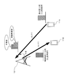
- a UL transmission signal of another UE 11 ⁇ / b> B located near the UE 11 ⁇ / b> A interferes with a DL reception signal from the eNB 12. obtain. If the UE 11A is located at the cell edge and the DL reception power from the eNB 12 is smaller than the interference power due to the UL transmission signal of the UE 11B, in the worst case, the UE 11A cannot receive the DL normally. .
- the DL transmission signal to the UE 11 may interfere with the UL reception signal from the UE 11.
- the base station 12 cannot perform UL reception normally.
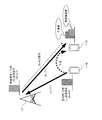
- a DL transmission signal to the UE 11 ⁇ / b> B may interfere with a UL signal received from another UE 11 ⁇ / b> A located in the vicinity of the eNB 12. If the UL reception power from the UE 11A located at the cell center is smaller than the DL transmission power to the UE 11B located at the cell edge, in the worst case, the eNB 12 cannot perform UL reception normally.
- the eNB 12 notifies the UE 11 of information regarding parameters used in other communication (communication of one or both of UL and DL) that may cause interference in the communication of the eNB 12 or the UE 11.
- information on parameters is information on code sequences used for one or both of signal scrambling and spreading (hereinafter, sometimes referred to as “code information” for convenience). Even if the same radio resource is used in different communications, the individual communications can be identified and separated by the code information.
- a code sequence used for scrambling may be referred to as a “scrambling code”, and a code sequence used for spreading may be referred to as a “spreading code”.
- orthogonal code may be used as the code.
- orthogonal codes include orthogonal variable spreading factor (Orthogonal Variable Spreading Factor, OVSF) code and Gold code.
- an OVSF code may be used as the channelization code
- a Gold code may be used as the scrambling code.
- “scrambling” is to multiply 1-bit information by a 1-bit or multiple-bit code
- “spreading” is to multiply 1-bit information by multiple-bit information. It is to be. Therefore, “scrambling” may be regarded as a concept including “diffusion”.
- Code information is not limited to information that explicitly (or directly) displays a code sequence.
- information that displays a code sequence implicitly (or indirectly), such as an identifier (ID) for identifying a code sequence or information used to generate a code sequence corresponds to “code information”. Also good.
- the eNB 12 may notify the UE 11 of code information used in another communication (second communication) that may interfere with a certain communication (first communication).
- the UE 11 may abbreviate an interference wave signal component (hereinafter referred to as an “interference signal”) due to other communication in a received signal (may be referred to as “desired wave signal”). ) Can be removed or suppressed. “Removal” may be rephrased as “cancel”, and “suppression” may be rephrased as “suppression” or “reduction”.
- the DL communication (reception) from the eNB 12 of the UE 11 corresponds to the “first communication”
- the UL communication (transmission) to the eNB 12 of the UE 11 is an interference source for the “first communication”. It corresponds to “second communication” that can be.
- DL communication (reception) from the eNB 12 of the first UE 11A corresponds to “first communication”
- UL communication transmission
- second communication can be an interference source for “first communication”.
- the UL communication (reception) from the UE 11 of the eNB 12 corresponds to the “first communication”
- the DL communication (transmission) to the UE 11 of the eNB 12 is an interference source for the “first communication”. This corresponds to “second communication” that can be.
- the UL communication (reception) from the first UE 11A of the eNB 12 corresponds to the “first communication”
- the DL communication to the second UE 11B of the eNB 12 corresponds to “second communication” that can be an interference source for “first communication”.
- the case of the previous item (1) is an example in which the UL transmission interferes with the DL reception of the UE 11 itself
- the case of the previous item (3) is an example in which the DL transmission interferes with the UL reception of the eNB 12 itself. It is.
- the code information used in each communication it may be considered that the code information used in each communication is known, so the “notification” of the code information may be unnecessary. However, “notification” is not prohibited.
- the code information used for DL transmission that can be an interference source for UL reception may be considered to be known in the eNB 12, and therefore “notification” of the code information may be unnecessary. However, “notification” is not prohibited.
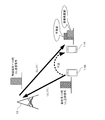
- the eNB 12 uses the code information Sc (spreading code or scrambling) used by the second UE 11B for UL transmission to the eNB 12 as shown in FIG. 4 at least in the case (2) of the previous section (2).
- code) # 2 may be notified to the first UE 11A.
- Sc # 1 represents code information used by the eNB 12 for DL transmission to the first UE 11A.
- Sc # 1 is an example of a first code sequence
- Sc # 2 is an example of a second code sequence.
- UE11A can identify the interference signal by UL transmission of other UE11B, and can remove or suppress an interference signal using the notified code information Sc # 2 in the DL reception signal from eNB12 become.
- the code information may be individually notified to a specific UE 11 or may be notified to a plurality of UEs 11. In other words, the code information may be included in broadcast information that the eNB 12 broadcasts to the radio area.
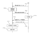
- FIG. 5 is a sequence diagram illustrating an operation example of the wireless communication system 1 according to the first embodiment.
- the eNB 12 may transmit a known signal periodically or aperiodically (processing P11).
- the known signal is a known signal between the UE 11 and the eNB 12, and may be, for example, a pilot signal.
- the pilot signal may be a DL common pilot signal.
- the common pilot signal may illustratively be a cell common reference signal (common RS) or a cell specific RS (cell specific RS).
- the UE 11 may measure the DL radio channel quality (processing P12 in FIGS. 5 and 7).
- the “wireless line” may be referred to as a “wireless channel”.
- the measurement of the radio channel quality by the UE 11 may be performed periodically or aperiodically.
- the index of “radio channel quality” is, for example, RS received power (RS received power, RSRP), RS received quality (RS received quality, RSRQ), RS SIR (RS signal to interference ratio, RS SIR) ), Channel quality indicator (channel quality indicator, CQI), and the like.
- the UE 11 may transmit the measurement result of the radio channel quality to the eNB 12 (may be referred to as “notification”) (processing P13 in FIGS. 5 and 7).
- the notification of the measurement result from the UE 11 to the eNB 12 may be performed periodically or aperiodically.
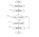
- ENB12 may perform "interference control", if the measurement result of radio channel quality is received from UE11 (process P14).
- the eNB 12 monitors and determines whether or not the measurement result of the radio channel quality is received from the UE 11 (processing P141). If the measurement result is received (YES), the received measurement result is predetermined. It may be determined whether it is lower than the threshold value (process P142).
- the eNB 12 may determine whether the received RSRQ is smaller than a predetermined threshold TH RSRQ .
- This determination corresponds to determining whether or not the measurement result of the DL radio channel quality at the UE 11 is lower than a predetermined threshold quality. In other words, this determination corresponds to determining whether or not the influence of interference due to other communication on the communication between the UE 11 and the eNB 12 is greater than a predetermined threshold.
- the eNB 12 performs other communication that may cause interference with the DL reception at the UE 11.
- Code information to be used may be determined (process P143). “Code information used in other communication that may cause interference” may be referred to as “interference wave code information” for convenience.
- the communication of other UE11 which uses one or both of the said UE11 own UL transmission, the same radio
- wireless resource for example, UL
- the eNB 12 may transmit and notify the determined interference wave code information to the transmission source UE 11 of the radio channel quality measurement result (process P15 in FIGS. 5 and 6). Thereafter, the eNB 12 may transmit a data signal (for example, user data) to the UE 11 (process P16 in FIG. 5).
- a data signal for example, user data
- the eNB 12 May transfer the process to process P141.
- the eNB 12 does not need to notify the UE 11 of the interference wave code information. However, even if the measurement result of the radio channel quality is equal to or higher than the threshold, the interference wave code information may be notified to the UE 11.
- the UE 11 determines whether or not code information (in other words, interference wave code information) used in other communication is received from the eNB 12 (processing P15a).
- code information in other words, interference wave code information
- the UE 11 uses the received code information to identify the interference signal included in the DL reception signal, and remove or suppress the interference signal (see FIG. 5 and process P17 of FIG. 7).
- the DL reception signal is, for example, a data signal transmitted from the eNB 12 to the UE 11 in the process P16 of FIG.
- the interference wave code information is a spreading code
- the UE 11 may demodulate and decode the received signal (process P18 in FIGS. 5 and 7). Thereby, the DL reception quality in the UE 11 can be improved, and the DL transmission speed and throughput can be improved.
- the UE 11 may demodulate and decode the received signal as usual (process P18).
- the information notified from the eNB 12 to the UE 11 for the removal or suppression of the interference signal is not limited to the interference wave code information.
- the eNB 12 notifies the UE 11 of information on one or both of the modulation scheme and the coding scheme used in other communication that may cause interference with the DL reception of the UE 11 together with the interference wave code information or individually. May be.
- An example of information regarding both the modulation scheme and the coding scheme is MCS information.
- MCS is an abbreviation for “modulation and coding” scheme.
- the UE 11 When the UE 11 demodulates and decodes the received signal, the UE 11 uses the information regarding one or both of the modulation scheme and the coding scheme of other communication notified from the eNB 12 to improve the identification accuracy of the interference signal included in the received signal. It can be improved. Therefore, UE11 can improve the removal performance or suppression performance of the interference signal contained in a received signal.
- Non-limiting examples of interference wave code information include spreading code, spreading code identifier (ID), scrambling code, scrambling code ID, information for generating scrambling code, etc. The same).
- Non-Patent Document 1 As an example of information for generating the scrambling code, as described in Sections 6.3.1 and 7.2 of Non-Patent Document 1, a slot number ( ns ), terminal identification information (C- RNTI, nRNTI ), cell ID (N Cell ID ), etc. (hereinafter the same).
- the eNB 12 may be implemented with a radio resource (which may be referred to as an “HD resource” for convenience) in which one or both of pilot signal transmission and code information notification are set for HD communication.
- a radio resource which may be referred to as an “HD resource” for convenience
- FD communication For communication after the code information is notified to the UE 11 using the HD resource, for example, transmission of a data signal from the eNB 12 to the UE 11 (processing P16), processing or control for interference removal or suppression can be performed in the UE 11. Therefore, FD communication is acceptable.
- the eNB 12 may switch the communication with the UE 11 after notifying the UE 11 of the code information from HD communication to FD communication.
- the eNB 12 may transmit a data signal to the UE 11 using a radio resource set for FD communication (may be referred to as “FD resource” for convenience).
- the radio channel quality measurement (process P12) at the UE 11 may be preferably performed in a situation where there is interference due to other communication, rather than in a situation where there is no interference due to other communication or a suppressed situation. is there.
- the interference wave code information may not be notified from the eNB 12 to the UE 11 in a situation where there is no interference due to other communication or in a suppressed situation (for example, NO in process P142 of FIG. 6).
- transmission of pilot signals may be performed with FD resources.
- the UE 11 may receive a pilot signal using the FD resource and transmit a measurement result of the radio channel quality to the eNB 12 using the HD resource.
- the notification of the interference wave code information to the UE 11 may be performed when the UE 11 requests the eNB 12 to transmit the code information.
- FIG. 10 shows an operation example of the wireless communication system 1 according to the second embodiment.
- FIG. 11 illustrates an operation example of the UE 11 according to the second embodiment
- FIG. 12 illustrates an operation example of the eNB 12 according to the second embodiment.
- the UE 11 may set a threshold value related to the radio channel quality (processing P22 and P32).
- the threshold value may be notified from the eNB 12 (processes P21 and P31), or may be stored in advance in the UE 11.
- the said threshold value may be a threshold value equivalent to the threshold value which eNB12 used for the comparison with the measurement result of radio channel quality in process P142 of 1st Example (FIG. 6) exemplarily.
- the UE 11 When the UE 11 receives a known signal (process P23 in FIG. 10) transmitted periodically or aperiodically by the eNB 12 (process P33 in FIG. 11), the UE 11 measures the radio channel quality in the same manner as in the first embodiment. (Process P24 in FIG. 10 and Process P34 in FIG. 11).
- the known signal may be a pilot signal, for example, as in the first embodiment.
- the UE 11 compares the measurement result with the set threshold value to determine whether the measurement result is less than the threshold value, in other words, the DL radio channel quality is equal to the predetermined threshold quality. Or lower (step P35 in FIG. 11).
- the UE 11 may request the eNB 12 for code information of other communication that may cause interference of DL reception, in other words, interference wave code information. (Process P25 in FIG. 10 and Process P36 in FIG. 11).
- the UE 11 does not need to request code information from the eNB 12. In this case, the UE 11 may demodulate and decode a DL signal (for example, a data signal) received thereafter as usual (processing P39).
- a DL signal for example, a data signal
- the eNB 12 may perform interference control when a code information request is received from the UE 11 (process P26 in FIG. 10). For example, as illustrated in FIG. 12, the eNB 12 monitors and determines whether a request for code information is received from the UE 11 (process P261).
- the eNB 12 may determine code information to be used in other communications that may cause interference with DL reception at the UE 11 (process P262).
- the eNB 12 may transmit and notify the determined code information to the requesting UE 11 (process P27 in FIGS. 10 and 12). After transmitting the code information, the eNB 12 may transmit a data signal to the UE 11 that is the code information request source (process P28 in FIG. 10).
- eNB12 may continue monitoring whether the request
- the UE 11 uses the code information to identify the interference signal included in the received signal, as in the first embodiment, and the interference signal Is removed or suppressed (process P29 in FIG. 10 and process P38 in FIG. 11).
- the received signal is, for example, a data signal transmitted from the eNB 12 to the UE 11 in the process P28 of FIG.
- the UE 11 may demodulate and decode the received signal after removing or suppressing the interference signal in the received signal (process P30 in FIG. 10 and process P39 in FIG. 11). Thereby, the DL reception quality in the UE 11 can be improved, and the DL transmission speed and throughput can be improved.
- the eNB 12 is one of the modulation scheme and the coding scheme used in other communications that may cause interference with the DL reception of the UE 11, for example, together with the interference wave code information or individually. Alternatively, the UE 11 may be notified of information regarding both.
- the notification of information regarding one or both of the modulation scheme and the coding scheme may also be performed by the eNB 12 receiving a request from the UE 11 in the same manner as the notification of the code information.
- the UE 11 may make a request for information regarding one or both of the modulation scheme and the coding scheme together with the request for code information or individually.
- the threshold notification (process P21), the pilot signal transmission (process P23), the code information request (process P25), and the code information notification (process P27) illustrated in FIG. Part or all may be implemented by HD communication (for example, refer to FIG. 13).
- the eNB 12 may allocate HD resources to some or all of threshold notification, pilot signal transmission, code information request, and code information notification.
- FD communication may be used.
- the eNB 12 may switch the communication with the UE 11 after notifying the UE 11 of the code information from HD communication to FD communication.
- the eNB 12 may perform transmission of a data signal to the UE 11 using FD resources.
- the radio channel quality measurement (process P24 in FIG. 10) at the UE 11 may be preferably performed in a situation where interference due to other communication exists, so that the pilot signal The transmission may be performed with FD resources.
- the UE 11 may receive the pilot signal with the FD resource and measure the radio channel quality, and may request the code information for the eNB 12 with the HD resource.
- FIG. 15 is a block diagram illustrating a configuration example of the eNB 12 according to an embodiment.
- the eNB 12 may exemplarily include an antenna 120, a transmission unit 121, a reception unit 122, and a control unit 123.
- the antenna 120 illustratively radiates a radio (RF) signal output from the transmission unit 121 to the space, receives an RF signal from the space, and outputs the RF signal to the reception unit 122.
- RF radio
- the antenna 120 is shared by the transmission unit 121 and the reception unit 122, but may be separate.
- the transmission unit 121 exemplarily generates a DL radio signal transmitted to the UE 11 and outputs the DL radio signal to the antenna 120.
- the receiving unit 122 illustratively receives a UL radio signal transmitted from the UE 11 and received by the antenna 120, and demodulates and decodes the received radio signal.
- the control unit 123 illustratively controls the operation of the transmission unit 121 (in other words, DL transmission processing) and the operation of the reception unit 122 (in other words, UL reception processing).
- the “transmission process” and the “reception process” may be referred to as “transmission operation” and “reception operation”, respectively.
- the transmission unit 121 may include a known signal generation unit 1211, a radio channel control information generation unit 1212, an encoding unit 1213, a scramble / modulation unit 1214, and a transmission radio unit 1215.
- the transmission unit 121 may be exemplarily provided with a broadcast information generation unit that acquires information broadcast to a radio area (e.g., a cell) provided by the eNB 12 and generates broadcast information.
- the broadcast information may include system information, information on radio resource control (RRC), and the like.
- the system information may include, for example, a master information block (master information block, MIB) and a system information block (system information block, SIB).
- the known signal generation unit 1211 exemplarily generates a known signal (for example, a pilot signal) to be transmitted to the radio area provided by the eNB 12 according to control by the control unit 123.
- a known signal for example, a pilot signal
- the radio channel control information generation unit 1212 exemplarily generates radio channel control information in accordance with control from the control unit 123 (for example, a radio channel control unit 1231 described later).
- the radio channel control information may include a message regarding a random access (RA) procedure with the UE 11, information regarding RRC, and the like.
- RA random access
- the interference wave code information described above may be included in the broadcast information or may be included in the control information of the radio channel.
- the control information for controlling switching between the FD communication and the HD communication described above (sometimes referred to as “FD / HD control information” for convenience) may be included in the broadcast information or wirelessly. It may be included in the channel control information.
- the above-described generation units 1211 and 1212 may be elements of the control unit 123.
- the encoding unit 1213 illustratively encodes an input signal.
- the input signal to the encoding unit 1213 is illustratively one of a DL transmission data signal, a known signal generated by the known signal generation unit 1211, and control information generated by the radio channel control information generation unit 1212. It may be one or more.
- notification information may also be input to the encoding unit 1213.
- the scramble / modulation unit 1214 illustratively scrambles and modulates the output signal of the encoding unit 1213.
- DL interference wave code information may be used for scrambling by the scramble / modulation section 1214.
- the interference wave code information may be scrambling code, spreading code, or information for generating scrambling code or spreading code.
- the transmission radio unit 1215 illustratively converts the frequency of the output signal of the scramble / modulation unit 1214 into a radio frequency to generate a DL radio signal.
- the DL radio signal may be appropriately amplified in the transmission radio unit 1225.
- control unit 123 for example, a base station setting control unit 1232 or a radio channel control unit 1231 described later. May be controlled by
- the reception unit 122 includes a reception radio unit 1221, a demodulation / descrambling unit 1222, an interference wave reception radio unit 1223, an interference wave demodulation / descramble unit 1224, a decoding unit 1225, and radio channel quality information extraction.
- a portion 1226 may be provided.
- the reception radio unit 1221 may illustratively amplify a UL radio signal received by the antenna 120 and convert it to a baseband signal.
- the demodulation / scramble unit 1222 illustratively demodulates and descrambles the output signal of the reception radio unit 1221.
- Interference wave reception radio section 1223 may exemplarily appropriately amplify an interference signal for the UL reception radio signal and convert it to a baseband signal. Note that since the interference reception signal is included in the UL reception radio signal, the interference wave reception radio unit 1223 and the reception radio unit 1221 may be integrated into one reception radio unit.
- the interference wave demodulation / descrambling unit 1224 illustratively interferes with the UL reception radio signal by demodulating and descrambling the output signal of the interference wave reception radio unit 1223 using the DL interference wave code information. Identify and extract signals.
- the interference signal identified and extracted by the interference wave demodulation / descrambling unit 1224 may be input to the demodulation / descrambling unit 1222.
- the demodulation / descrambling unit 1222 subtracts the interference signal input from the interference wave demodulation / descrambling unit 1224 from, for example, the signal input from the reception radio unit 1221, thereby removing or suppressing the interference signal. Do.
- the decoding unit 1225 decodes the received signal from which the interference signal is removed or suppressed in the demodulation / descrambling unit 1222 as described above.
- the radio channel quality information extraction unit 1226 illustratively extracts information on the radio channel quality from the received signal decoded by the decoding unit 1225.
- the information regarding the radio channel quality may be, for example, the above-described RSRP, RSRQ, RS SIR, CQI, or the like.
- the information on the extracted radio channel quality may be input to the control unit 123 (for example, the radio channel control unit 1231) and used for controlling the radio channel, for example.
- Radio channel quality information extraction section 1226 may be an element of control section 123.
- the control unit 123 may exemplarily include a radio channel control unit 1231, a base station setting control unit 1232, and a storage unit 1233.
- the radio channel control unit 1231 illustratively controls a radio channel with the UE 11.
- control related to removal or suppression of the interference signal described above may be referred to as “interference control” for convenience
- control related to the RA procedure may be included.
- FD communication for convenience
- HD communication Control related to switching between the two
- control unit 123 can be regarded as functioning as a notification unit for notifying the UE 11 by including the interference wave code information in the broadcast information or the control information of the radio channel.
- Information regarding control of the radio channel may be transmitted / received as appropriate by communication with a core node (for example, the MME 32) or another eNB 12, for example.
- the communication between the eNBs 12 may be exemplarily performed on the X2 interface.
- the X2 interface is an example of a communication interface between base stations.
- the base station setting control unit 1232 illustratively controls the setting of one or both of the transmission operation of the transmission unit 121 and the reception operation of the reception unit 122.
- the transmission operation setting control for the transmission unit 121 may be, for example, setting control for any one or more of the encoding unit 1213, the scramble / modulation unit 1214, and the transmission radio unit 1215.
- the setting control for the encoding 1213 may include setting control related to the encoding method, the encoding rate, and the like, for example.
- the setting control for the scramble / modulation unit 1214 may include setting control related to scramble processing and modulation scheme, for example.
- the setting control for the transmission radio unit 1215 may include setting control related to the transmission power of the DL radio signal, for example.
- the reception operation setting control for the reception unit 122 includes any one of the reception radio unit 1221, the demodulation / descrambling unit 1222, the interference wave reception radio unit 1223, the interference wave demodulation / descrambling unit 1224, and the decoding unit 1225. It may be setting control for one or more.
- the setting control for one or both of the reception radio unit 1221 and the interference wave reception radio unit 1223 may include setting control related to the amplification factor of the reception radio signal, for example.
- the setting control for the demodulation / descrambling unit 1222 may include, for example, setting control regarding descrambling processing and demodulation method corresponding to the scrambling processing and modulation method used for the UL RF signal transmitted by the UE 11. .
- the setting control for the interference wave demodulation / descrambling unit 1224 may include, for example, setting control for interference wave code information, setting control for descrambling processing based on interference wave code information, setting control for demodulation method, and the like. .
- the setting control for the decoding unit 1225 may include, for example, setting control related to a decoding process corresponding to a coding scheme and a coding rate used for the UL RF signal transmitted by the UE 11.
- the storage unit 1233 may exemplarily store system information, interference wave code information, FD / HD control information, and the like. Note that the information stored in the storage unit 1233 may be appropriately transmitted and received through communication with the core node (for example, the MME 32) or another eNB 12.
- FIG. 16 is a block diagram illustrating a configuration example of the UE 11 according to an embodiment.
- the UE 11 illustrated in FIG. 16 may include an antenna 110, a transmission unit 111, a reception unit 112, and a control unit 113, for example.
- the antenna 110 illustratively radiates the RF signal output from the transmission unit 111 to the space, receives the RF signal from the space, and outputs the RF signal to the reception unit 112.
- the antenna 110 is shared by the transmission unit 111 and the reception unit 112, but may be separate.
- the transmission unit 111 illustratively generates a UL RF signal to be transmitted to the eNB 12 and outputs the UL RF signal to the antenna 110.
- the receiving unit 112 illustratively receives a DL RF signal transmitted from the eNB 12 and received by the antenna 110, and demodulates and decodes the received RF signal.
- the control unit 113 illustratively controls the operation of the transmission unit 111 (in other words, UL transmission processing) and the operation of the reception unit 112 (in other words, DL reception processing).
- transmission processing and “reception processing” may be considered to be synonymous with the above-described “transmission operation” and “reception operation”, respectively.
- the transmission unit 111 may exemplarily include a radio channel quality information generation unit 1111, a control information generation unit 1112, an encoding unit 1113, a scramble / modulation unit 1114, and a transmission radio unit 1115.
- the radio channel quality information generation unit 1111 exemplarily shows information on radio channel quality transmitted to the eNB 12 based on the radio channel quality measured by the radio channel quality measurement unit 1128 described later (hereinafter, “radio channel quality information”). May be abbreviated to be generated).
- the “radio channel quality information” may be, for example, the aforementioned RSRP, RSRQ, RS SIR, CQI, or the like.
- the control information generation unit 1112 exemplarily acquires control information regarding control of the radio channel with the eNB 12 from the control unit 113 (for example, a radio channel control unit 1131 described later), and transmits the control information to the eNB 12 Is generated.
- Radio channel control includes, for example, cell selection control, RA procedure control, RRC connection control, interference wave code information reception and request control, and switching between FD communication and HD communication. Control etc. may be included.
- radio channel quality information generation unit 1111 and the control information generation unit 1112 may be elements of the control unit 113.
- the encoding unit 1113 illustratively encodes the input signal.
- Examples of the input signal to the encoding unit 1113 include a UL transmission data signal, radio channel quality information generated by the radio channel quality information generation unit 1111, and control information generated by the control information generation unit 1112. Any one or more of these may be sufficient.
- the scramble / modulation unit 1114 illustratively scrambles and modulates the output signal of the encoding unit 1113.
- the encoding method and the encoding rate in the encoding unit 1113 may be exemplarily controlled by the control unit 113 (for example, a terminal setting control unit 1132, which will be described later, or a radio channel control unit 1131).
- the control unit 113 for example, a terminal setting control unit 1132, which will be described later, or a radio channel control unit 1131.
- the scramble processing and modulation method in the scramble / modulation unit 1114 may be controlled by the control unit 113 (for example, the terminal setting control unit 1132 or the radio channel control unit 1131), for example.
- the transmission radio unit 1115 illustratively converts the frequency of the signal input from the scramble / modulation unit 1114 into a radio frequency to generate a UL RF signal.
- the UL RF signal may be appropriately amplified in transmission radio section 1115.
- the reception unit 112 includes a reception radio unit 1121, a demodulation / descrambling unit 1122, an interference wave reception radio unit 1123, an interference wave demodulation / descramble unit 1124, and a decoding unit 1125. It's okay.
- the reception unit 112 may include a radio channel control information extraction unit 1126, a pilot signal extraction unit 1127, and a radio channel quality measurement unit 1128.
- Receiving radio section 1121 may exemplarily amplify a DL RF signal received by antenna 110 and convert it into a baseband signal.
- the demodulation / descrambling unit 1122 illustratively demodulates and descrambles the output signal of the reception radio unit 1121.
- the interference wave reception radio unit 1123 may exemplarily appropriately amplify an interference signal with respect to a DL reception radio signal and convert the interference signal to a baseband signal. Since an interference signal is included in the DL reception radio signal, the interference wave reception radio unit 1123 and the reception radio unit 1121 may be integrated into one reception radio unit.
- the interference wave demodulation / descrambling unit 1124 exemplarily interferes with the UL reception radio signal by demodulating and descrambling the output signal of the interference wave reception radio unit 1123 using the UL interference wave code information. Identify and extract signals.
- the UL interference wave code information may be, for example, code information notified from the eNB 12 and may be stored in the control unit 113 (for example, a storage unit 1133 described later).
- the interference signal identified and extracted by the interference wave demodulation / descrambling unit 1124 may be input to the demodulation / descrambling unit 1122.
- the demodulation / descrambling unit 1122 subtracts the interference signal input from the interference wave demodulation / descrambling unit 1124 from, for example, the signal input from the reception radio unit 1121, thereby removing or suppressing the interference signal.
- the decoding unit 1125 decodes the reception signal from which the interference signal is removed or suppressed in the demodulation / descrambling unit 1122 as described above.
- the radio channel control information extraction unit 1126 illustratively extracts radio channel control information from the reception signal decoded by the decoding unit 1125.
- the radio channel control information may include, for example, a message related to the RA procedure, interference wave code information, FD / HD control information, and the like.
- the extracted control information may be input to the control unit 113 (for example, a radio channel control unit 1131 described later), for example.
- the pilot signal extraction unit 1127 illustratively extracts a pilot signal from the reception signal decoded by the decoding unit 1125.
- the extracted pilot signal (in other words, the received pilot signal) may be input to the radio channel quality measurement unit 1128, for example.
- the radio channel quality measurement unit 1127 illustratively measures DL radio channel quality (for example, RSRP, RSRQ, RS SIR, CQI, etc. described above) based on the received pilot signal.
- the measurement result may be input to the control unit 113 (for example, a radio channel control unit 1131 described later). Further, the measurement result may be input to the radio channel quality information generation unit 1111 of the transmission unit 111 in order to notify (feedback) to the eNB 12.
- the receiving unit 112 may be provided with a broadcast information extracting unit that extracts broadcast information from the reception signal decoded by the decoding unit 1125.
- Interference wave code information and FD / HD control information may be set in the broadcast information.
- extraction units 1126 and 1127, the generation units 1111 and 1112, and the radio channel quality measurement unit 1128 described above may be elements of the control unit 113.
- the control unit 113 may include a radio channel control unit 1131, a terminal setting control unit 1132, and a storage unit 1133 as illustrated in FIG. 16.
- the radio channel control unit 1131 illustratively controls a radio channel with the eNB 12 based on information stored in the storage unit 1133, control information extracted from the received signal, and the like.
- the control of the radio channel includes, for example, control related to cell selection, control related to RA procedure, control related to reception and request of interference wave code information, control related to switching between FD communication and HD communication, and the like. Good.
- the terminal setting control unit 1132 illustratively controls the setting of one or both of the transmission operation of the transmission unit 111 and the reception operation of the reception unit 112.
- the storage unit 1133 illustratively stores and manages system information, interference wave code information, FD / HD control information, and the like.
- the FD / HD control information may be information stored in advance in the storage unit 1133 or may be information included in the broadcast information broadcast from the eNB 12.
- the transmission operation setting control for the transmission unit 111 may be, for example, setting control for any one or more of the encoding unit 1113, the scramble / modulation unit 1114, and the transmission radio unit 1115.
- the setting control for the encoding unit 1113 may include setting control related to the encoding scheme and the encoding rate, for example.
- the setting control for the scramble / modulation unit 1114 may include setting control related to scramble processing and modulation scheme, for example.
- the setting control for the transmission radio unit 1115 may include, for example, setting control related to the transmission power of the UL RF signal.
- the setting control of the receiving operation for the receiving unit 112 may be, for example, a setting control for any one or more of the units 1121 to 1125 and 1128.
- the setting control for one or both of the reception radio unit 1121 and the interference wave reception radio unit 1123 may include setting control related to the amplification factor of the DL reception RF signal, for example.
- the setting control for the demodulation / descrambling unit 1122 may include, for example, setting control related to the demodulation method corresponding to the modulation method used for the DL RF signal transmitted by the eNB 12 and setting control related to the descrambling process. .
- the setting control for the interference wave demodulation / descrambling unit 1124 may include, for example, setting control related to interference wave code information, setting control related to descrambling processing based on interference wave code information, setting control related to a demodulation method, and the like. .
- the setting control for the decoding unit 1125 may include, for example, setting control related to a decoding process corresponding to the coding scheme and coding rate used for the DL RF signal transmitted by the eNB 12.
- the setting control for the radio channel quality measurement unit 1128 may include setting control related to the measurement timing of the radio channel quality.
- the radio channel quality measurement unit 1128 may be set and controlled to measure the radio channel quality during the FD communication implementation period as described above.
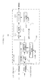
- interference suppression processing Next, a configuration example of a processing unit that removes or suppresses interference signals will be described with reference to FIGS. 17 and 18. Note that the processing unit that removes or suppresses the interference signal may be referred to as an “interference suppression processing unit”, an “interference control unit”, or an “interference canceller” for convenience.
- FIG. 17 is a block diagram illustrating a first configuration example of the interference canceller according to the embodiment
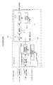
- FIG. 18 is a block diagram illustrating a second configuration example of the interference canceller according to the embodiment.
- the interference canceller 20 of the first configuration example may exemplarily include a demodulation / descrambling unit 21 and an interference wave demodulation / descrambling unit 22.
- the interference canceller 20 may be applied to each of the reception unit 112 of the UE 11 illustrated in FIG. 16 and the eNB 12 illustrated in FIG.
- the demodulation / descrambling unit 21 in FIG. 17 may correspond to the demodulation / descrambling unit 1122 in FIG. 16 and the demodulation / descrambling unit 1222 in FIG.
- the interference wave demodulation / descramble unit 22 in FIG. 17 may correspond to the interference wave demodulation / descramble unit 1124 in FIG. 16 and the interference wave demodulation / descramble unit 1224 in FIG.
- the demodulation / descrambling unit 21 may include an adder 211, a demodulation unit 212, a descrambling unit 213, and a scrambling code generation unit 214, for example.
- the interference wave demodulation / descrambling unit 22 may include, for example, an interference wave demodulation unit 221, a correlation calculation unit 222, and an interference wave scrambling code generation unit 223.
- the adder 211 adds the reception signal output from the reception radio unit 1121 (or 1221) and the output signal of the interference wave demodulation / descrambling unit 22.
- the output signal of the interference wave demodulation / descrambling unit 22 is, for example, an interference signal having a negative value. Accordingly, the adder 211 substantially subtracts the interference signal from the received signal. Thereby, an interference signal is removed or suppressed in the received signal. Note that the adder 211 may be replaced with a subtractor if the sign of the output signal of the interference wave demodulation / descramble unit 22 is inverted.
- the demodulator 212 illustratively demodulates the received signal from which the interference signal has been removed or suppressed by the adder 211. Therefore, the reception SIR of the demodulated signal is improved.
- the descrambling unit 213 illustratively descrambles the signal demodulated by the demodulating unit 212 using the scrambling code generated by the scrambling code generating unit 214.
- the scrambling code generation unit 214 illustratively receives input of information for generating a scrambling code and generates a scrambling code.
- the scrambling code is an example of a code for receiving and identifying a desired wave signal.
- Information for generating a scrambling code may be provided from the control unit 113 (for example, the terminal setting control unit 1132) in the UE 11, and from the control unit 123 (for example, the base station setting control unit 1232) in the eNB 12. May be.
- the interference wave demodulation unit 221 illustratively demodulates a signal input from the interference reception radio unit 1123 (or 1223).
- the correlation calculation unit 222 illustratively calculates the correlation between the signal demodulated by the interference wave demodulation unit 221 and the scrambling code of the interference signal generated by the interference wave scrambling code generation unit 223. Then, correlation calculation section 222 identifies a signal having a relatively high correlation in the correlation calculation result as an interference signal (may be referred to as “specification”), and outputs the specified interference signal to adder 211. .
- the above demodulation and correlation calculation by the interference wave demodulation unit 221 and the correlation calculation unit 222 may be regarded as a process of demodulating and regenerating the interference signal included in the received signal.
- the interference wave scrambling code generation unit 223 illustratively receives the input of the interference wave code information and generates a scrambling code used for correlation calculation by the correlation calculation unit 222.
- the interference wave code information may be provided from the control unit 113 (for example, the terminal setting control unit 1132) in the UE 11, and may be provided from the control unit 123 (for example, the base station setting control unit 1232) in the eNB 12.
- the scrambling code used for correlation calculation in the reception unit 112 of the UE 11 may be a scrambling code used for UL communication of another UE 11. Since the eNB 12 knows the scrambling code used by other UEs 11 for UL communication, as described above, the eNB 12 is notified of the interference wave code information.
- the scrambling code used for correlation calculation in the reception unit 122 of the eNB 12 may be a scrambling code used by the eNB for DL transmission or a scrambling code used by another UE 11 for UL transmission.
- the eNB 12 knows these scrambling codes, and therefore does not have to receive notification of interference wave code information.
- the correlation calculation by the correlation calculation unit 222 may be performed using each of the scrambling codes used in the plurality of other communications if there are a plurality of other communications that may cause interference. For example, if a plurality of scrambling codes are notified from the eNB 12 as interference wave code information in the UE 11, the correlation between each of the scrambling codes and the signal demodulated by the interference wave demodulation unit 221 is a correlation calculation unit. It may be calculated at 222.
- the reception unit 112 (or 122) identifies the interference signal component by descrambling the reception signal using the interference wave code information. Then, descrambling using a scrambling code for receiving and identifying the desired wave signal is applied to the result of subtracting the identified interference signal component from the received signal. Thereby, the reception SIR of the desired wave signal can be improved.
- the interference canceller 40 illustrated in FIG. 18 differs from the first configuration example illustrated in FIG. 17 in that a spreading code is used instead of the scrambling code.
- the interference canceller 40 includes a demodulation / despreading unit 41 including a despreading unit 413 and a spreading code generation unit 414, and an interference wave demodulation / despreading unit 42 including a despreading unit 422 and an interference wave spreading code generation unit 423. , May be provided.
- the demodulation / despreading unit 41 may include, for example, an adder 411 and a demodulation unit 412 in addition to the despreading unit 413 and the spreading code generation unit 414.
- the adder 411 and the demodulator 412 may be equivalent to the adder 211 and the demodulator 212 illustrated in FIG.
- the despreading unit 413 despreads the signal demodulated by the demodulating unit 412 using the spreading code of the interference signal generated by the spreading code generating unit 414.
- the interference wave demodulation / despreading unit 42 may include, for example, an interference wave demodulation unit 421.
- the interference wave demodulation unit 421 may be equivalent to the interference wave demodulation unit 221 illustrated in FIG.
- the despreading unit 422 despreads the signal demodulated by the interference wave demodulation unit 421 using the interference signal spreading code generated by the interference wave spreading code generation unit 423.
- the interference canceller 40 illustrated in FIG. 18 may be applied to each of the reception unit 112 of the UE 11 illustrated in FIG. 16 and the eNB 12 illustrated in FIG. 15, as in the first configuration example illustrated in FIG. .
- the demodulation / descrambling unit 1122 in FIG. 16 and the demodulation / descrambling unit 1222 in FIG. 15 may be replaced with the demodulation / despreading unit 41 in FIG.
- the interference wave demodulation / descrambling unit 1124 in FIG. 16 and the interference wave demodulation / descrambling unit 1224 in FIG. 15 may be replaced with the interference wave demodulation / despreading unit 42 in FIG.
- the spreading code generating unit 414 receives the input of the interference wave code information and generates a spreading code, for example.
- Information for generating the spreading code may be given from the control unit 113 (for example, the terminal setting control unit 1132) in the UE 11, and from the control unit 123 (for example, the base station setting control unit 1232) in the eNB 12. It's okay.
- the interference wave spreading code generation unit 423 receives input of information for generating a spreading code of the interference signal and uses it for the despreading in the despreading unit 422. Generated spreading code.
- the interference wave code information may be provided from the control unit 113 (for example, the terminal setting control unit 1132) in the UE 11, and may be provided from the control unit 123 (for example, the base station setting control unit 1232) in the eNB 12.
- the interference signal is extracted and identified by despreading by the despreading unit 422, and the interference signal is input to the adder 411.
- the adder 411 exemplarily adds the reception signal output from the reception radio unit 1121 (or 1221) and the interference signal obtained in the interference wave demodulation / despreading unit 42.
- the interference signal output from the interference wave demodulation / despreading unit 42 may have a negative value. Accordingly, the adder 411 substantially subtracts the interference signal from the received signal. Thereby, an interference signal is removed or suppressed in the received signal. Note that the adder 411 may be replaced with a subtractor if the sign of the output signal of the interference wave demodulation / despreading unit 42 is inverted.
- the received signal from which the interference signal has been removed or suppressed by the adder 411 is demodulated by the demodulator 412 and despread by the despreader 413. Therefore, the reception SIR of the reception signal is improved. Further, in the second configuration example, gain improvement by despreading can be expected as compared with the first configuration example.
- the spreading code used for despreading may be a spreading code used for UL communication of other UEs 11. Since the eNB 12 knows the spreading code used by other UEs 11 for UL communication, the eNB 12 is notified as interference wave code information as described above.
- the spreading code used for despreading may be a spreading code used by the eNB for DL transmission or a spreading code used by another UE 11 for UL transmission.
- the eNB 12 knows these spreading codes, and therefore does not have to receive notification of interference wave code information.
- the despreading in the despreading unit 422 may be performed using each of the spreading codes used in a plurality of other communications if there are a plurality of other communications that may cause interference. For example, if a plurality of spreading codes are notified from the eNB 12 as interference wave code information in the UE 11, the signal demodulated by the interference wave demodulating unit 421 using each of the spreading codes is despread in the despreading unit 422. May be diffused.
- NAICS is an abbreviation for “network-assisted interference cancellation and suppression”.
- MU-MIMO is an abbreviation for “multi user multiple-input and multiple-output”.
- SU-MIMO is a technology that improves transmission capacity (for example, the amount of information that can be transmitted in one transmission) by setting a plurality of transmission paths between a base station and one wireless terminal, for example.
- Information transmitted through the transmission path is referred to as a “stream”.
- each stream is multiplied by a code at the time of transmission, and the stream is separated using the code on the receiving side.
- Precoding is used, for example, for W-CDMA or LTE MIMO transmission.
- W-CDMA is an abbreviation of “wideband code division multiple access”.
- MU-MIMO uses a plurality of streams transmitted through a plurality of transmission paths by a plurality of wireless terminals using precoding. Thereby, in MU-MIMO, it is possible to perform communication simultaneously with a plurality of wireless terminals using the same wireless resource.
- NAICS NAICS is studied as an example of countermeasures against the interference.
- NAICS is based on the assumption of SU-MIMO as described above, it is assumed that DL signals intended for other radio terminals interfere with DL reception desired wave signals in the radio terminals, and interference is eliminated.
- the object to be suppressed is a DL signal.
- the above-described embodiment includes a case where a UL transmission signal interferes with a DL reception signal.
- the transmission source of the UL transmission signal is the wireless terminal itself or another wireless terminal.
- the transmission source of the UL transmission signal is another wireless terminal
- the terminal identification information for example, C-RNTI
- the scrambling code generated using the terminal identification information is also different.
- W-CDMA since the radio resources are divided and identified by the spreading code, in the MU-MIMO transmission, the same spreading code may be used for the same radio terminal. Therefore, in W-CDMA MU-MIMO transmission, a wireless terminal can remove or suppress interference if it knows its own spreading code information without knowing the spreading code information of other wireless terminals. is there.
- the wireless terminal needs to know the code information that the other wireless terminal uses for UL transmission.
- the wireless terminal cannot identify and specify another wireless terminal that is the source of the UL signal that causes interference.
- the base station can know the transmission source terminal of the UL signal that causes interference.
- the interference wave code information to be notified from the eNB 12 to the UE 11 may be code information used in all communications by the eNB 12.
- the eNB 12 may notify the code information used in all communications to the UE 11 at the time of setting a radio channel with the UE 11, and the UE 11 may store the notified code information.
- FIG. 19 (A) and FIG. 19 (B) schematically show an example.
- the eNB 12 can communicate with the UE 11A and the UE 11B.
- the eNB 12 performs DL transmission to the first UE 11A using the first scrambling code (or spreading code) Sc # 1. Also, the second UE 11B performs UL transmission to the eNB 12 using the second scrambling code (or spreading code) Sc # 2.
- the first UE 11A performs UL transmission to the eNB 12 using the third scrambling code (or spreading code) Sc # 3. Further, the eNB 12 performs DL transmission to the second UE 11B using the fourth scrambling code (or spreading code) Sc # 4.
- the UL and DL communications illustrated in FIGS. 19A and 19B may be performed at the same frequency (f1), may be performed at different times, or may be performed at the same time. May be implemented. However, inter-signal interference becomes a problem in simultaneous communication using the same frequency (f1).
- the eNB 12 transmits all of the first to fourth scrambling codes (or spreading codes) Sc # 1 to Sc # 4 to the first UE 11A without being limited to the second scrambling code (or spreading code) Sc # 2. May be notified.
- Sc # 1 to Sc # 4 are examples of the first to fourth code sequences, respectively.
- the first UE 11A performs DL reception using the first scrambling code (or spreading code) Sc # 1 and UL transmission using the third scrambling code (or spreading code) at the same frequency (f1). ) At the same time.
- the UE 11A can perform FD communication with the eNB 12 using the same radio resource.
- the control unit 123 includes the transmission unit 121 and the reception so that the DL transmission by the transmission unit 121 and the UL reception by the reception unit 122 are performed at the same frequency (f1).
- the operation of the unit 122 may be controlled.
- code information may be stored in advance in the UE 11 (for example, the storage unit 1133 in FIG. 16), for example, code information used in all communications when the UE 11 is manufactured.
- the interference wave code information may be transmitted / received between the eNBs 12 as an example.
- transmitting / receiving the interference wave code information between the eNBs 12 for example, it is possible to remove or suppress interference between the UEs 11 connected to different eNBs 12.
Landscapes
- Engineering & Computer Science (AREA)
- Computer Networks & Wireless Communication (AREA)
- Signal Processing (AREA)
- Mobile Radio Communication Systems (AREA)
Abstract
基地局(12)は、第1のコード系列を用いてスクランブリングした下り信号を、前記第1の端末(11A)へ送信する。また、基地局(12)は、第2の端末(11B)が上り信号のスクランブリングに用いる第2のコード系列に関する情報を、第1の端末(11A)に通知する。第1の端末(11A)は、前記第1のコード系列と前記第2のコード系列とを用いて、前記下り信号の受信処理を行なう。
Description
本明細書に記載する技術は、無線通信システム、基地局、及び、端末に関する。
通信の態様として、全二重(full duplex, FD)通信と半二重(half duplex, HD)通信とが知られている。
FD通信では、送信を行ないながら受信を行なうことが可能である。FD通信は、例えば、送信と受信とで異なる周波数を用いる周波数分割複信(frequency division duplex, FDD)で実施される。
これに対し、HD通信では、或る時間において送信及び受信の一方のみを行なう。HD通信は、例えば、送信と受信とで同一周波数を用い、送信と受信とを時間的に分ける時分割複信(time division duplex, TDD)で実施される。
3GPP TS36.V211 V8.9.0 (2009-12)
3GPP TR25.766 V13.0.0 (2015-09)
無線通信システムにおいて、例えば、基地局と端末との間で、1つの周波数帯域においてFD通信を実施しようとすると、或る端末の下り(ダウンリンク,DL)の受信に対して、他の端末の上り(アップリンク,UL)の送信が干渉し得る。当該干渉が生じると、端末でのDLの受信品質が低下する。
1つの側面では、本明細書に記載する技術の目的の1つは、基地局から端末への下り信号の受信品質を向上することにある。
1つの側面において、無線通信システムは、基地局と、基地局と通信する第1の端末と、基地局と通信する第2の端末と、を備えてよい。基地局は、送信部と制御部とを備えてよい。送信部は、第1のコード系列を用いてスクランブリングした下り信号を、前記第1の端末へ送信してよい。制御部は、前記第2の端末が上り信号のスクランブリングに用いる第2のコード系列に関する情報を、前記第1の端末に通知してよい。一方、前記第1の端末は、前記第1のコード系列と前記第2のコード系列とを用いて、前記下り信号の受信処理を行なう受信部を備えてよい。
また、1つの側面において、基地局は、送信部と制御部とを備えてよい。送信部は、第1のコード系列を用いてスクランブリングした下り信号を、第1の端末へ送信してよい。制御部は、第2の端末が上り信号のスクランブリングに用いる第2のコード系列に関する情報を、前記第1の端末に通知してよい。
更に、1つの側面において、基地局と通信する第1及び第2の端末のうちの前記第1の端末は、受信部と制御部とを備えてよい。受信部は、基地局が第1のコード系列を用いてスクランブリングした下り信号を受信してよい。制御部は、前記第2の端末が前記基地局へ送信する上り信号のスクランブリングに用いる第2のコード系列に関する情報を、前記基地局から受信してよい。そして、受信部は、前記第1のコード系列と前記第2のコード系列とを用いて、前記下り信号の受信処理を行なってよい。
1つの側面として、基地局から端末への下り信号の受信品質を向上できる。
以下、図面を参照して実施の形態を説明する。ただし、以下に説明する実施形態は、あくまでも例示であり、以下に明示しない種々の変形や技術の適用を排除する意図はない。また、以下に説明する各種の例示的態様は、適宜に組み合わせて実施しても構わない。なお、以下の実施形態で用いる図面において、同一符号を付した部分は、特に断らない限り、同一若しくは同様の部分を表す。
図1は、一実施形態に係る無線通信システムの構成例を示すブロック図である。図1に示す無線通信システム1は、例示的に、無線端末11と、基地局12と、コアネットワーク13と、を備えてよい。なお、図1の例では、1台の無線端末11と1台の基地局12とに着目しているが、無線端末11及び基地局12は、いずれも、無線通信システム1において2台以上存在してよい。
無線端末11は、基地局12が形成又は提供する無線エリアにおいて基地局12と無線通信することが可能である。「無線端末」は、「無線デバイス」、「無線装置」、あるいは「端末装置」等と称されてもよい。
無線端末11は、その位置が変化しない固定端末であってもよいし、その位置が変化する移動端末(「移動機」と称してもよい。)であってもよい。非限定的な一例として、無線端末11は、携帯電話やスマートフォン、タブレット端末等の移動可能なUEであってよい。「UE」は、「User Equipment」の略称である。
基地局12は、無線端末11との無線通信を可能にする無線エリアを形成又は提供する。「無線エリア」は、「セル」、「カバレッジエリア」、「通信エリア」、「サービスエリア」等と称されてもよい。
基地局12は、例示的に、3rd generation partnership project(3GPP)のlong term evolution(LTE)やLTE-Advanced(以下「LTE」と総称する。)に準拠した「eNB」であってよい。
「eNB」は、「evolved Node B」の略称である。なお、remote radio equipment(RRE)やremote radio head(RRH)等と称される、基地局本体から分離されて遠隔地に配置された通信ポイントが、基地局12に該当してもよい。
基地局12が形成又は提供する「セル」は「セクタセル」に分割されてもよい。「セル」には、マクロセルやスモールセルが含まれてよい。スモールセルは、マクロセルよりも電波到達範囲(カバレッジ)の小さいセルの一例である。
スモールセルは、カバレッジエリアに応じて呼称が異なってよい。例えば、スモールセルは、「フェムトセル」、「ピコセル」、「マイクロセル」、「ナノセル」、「メトロセル」、「ホームセル」等と称されてもよい。
コアネットワーク13には、図1に例示するように、SGW31、MME32、及び、PGW33が含まれてよい。「SGW」は、「Serving Gateway」の略称である。「PGW」は、「Packet Data Network Gateway」の略称である。「MME」は、「Mobility Management Entity」の略称である。
コアネットワーク13は、基地局12に対する「上位ネットワーク」に相当すると捉えてよい。SGW31、MME32、及び、PGW33は、「コアネットワーク」のエレメント(NE)あるいはエンティティに相当すると捉えてよく、「コアノード」と総称してよい。
基地局12は、コアネットワーク13に、有線インタフェースの一例である「S1インタフェース」によって接続されてよい。ただし、基地局12は、無線インタフェースによってコアネットワーク13と通信可能に接続されても構わない。
基地局12とコアネットワーク13とを含むネットワークは、無線アクセスネットワーク(RAN)と称されてもよい。RANの一例は、「Evolved Universal Terrestrial Radio Access Network, E-UTRAN」である。
また、基地局12は、例示的に、SGW31及びMME32と通信可能に接続されてよい。基地局12と、SGW31及びMME32と、の間は、例えば、S1インタフェースと称されるインタフェースによって通信可能に接続されてよい。
SGW31は、S5インタフェースと称されるインタフェースによってPGW33と通信可能に接続されてよい。PGW33は、インターネットやイントラネット等のパケットデータネットワーク(PDN)と通信可能に接続されてよい。
SGW31及びPGW33を介して、無線端末11とPDNとの間でユーザパケットの送受信が可能である。ユーザパケットは、ユーザデータの一例であり、ユーザプレーン信号と称してもよい。
例示的に、SGW31は、ユーザプレーン信号を処理してよい。制御プレーン信号は、MME32が処理してよい。SGW31は、S11インタフェースと称されるインタフェースによってMME32と通信可能に接続されてよい。
MME32は、例示的に、無線端末11の位置情報を管理する。SGW31は、MME32で管理されている位置情報を基に、例えば、無線端末11の移動に伴うユーザプレーン信号のパス切り替え等の移動制御を実施してよい。移動制御には、無線端末11のハンドオーバに伴う制御が含まれてよい。
eNBが形成する無線エリアは、「セル」又は「セクタ」であってよい。eNBが形成するセルは、「マクロセル」と称されてよい。マクロセルを形成する無線基地局(eNB)は、「マクロ基地局」、「マクロeNB」、又は、「MeNB」等と称されてもよい。
eNBが形成する無線エリアは、「セル」又は「セクタ」であってよい。eNBが形成するセルは、「マクロセル」と称されてよい。マクロセルを形成する無線基地局(eNB)は、「マクロ基地局」、「マクロeNB」、又は、「MeNB」等と称されてもよい。
なお、「セル」は、無線基地局が送信する無線電波の到達可能範囲(「カバレッジ」と称してもよい。)に応じて形成される無線エリアの一例である。セル内に位置する移動局等の無線機器が、当該セルを形成する無線基地局と無線通信することが可能である。
LTEでは、マクロセルの他にスモールセル(SC)を活用してシステム容量の増大を図る技術に関する議論が行なわれている。例えば、マクロセル(MC)に、マクロセルよりもカバレッジの小さい「スモールセル」が配置されることがある。
「スモールセル」には、例示的に、「ホームセル」、「フェムトセル」、「ピコセル」、「マイクロセル」、「メトロセル」等と称されるセルが含まれてよい。
eNB12は、UE11との通信に用いる無線リソースの設定(「割当」と称してもよい。)を制御してよい。当該制御は、「スケジューリング」と称されてもよい。無線リソース(単に「リソース」と称することもある)は、例示的に、周波数領域及び時間領域によって2次元的に区別されてよい。
eNB12は、UE11との通信に利用可能な無線リソースを、周波数領域及び時間領域で分割した単位でスケジューリングを実施してよい。
UE11とeNB12との間の無線通信には、時分割複信(Time Division Duplex:TDD)、及び、周波数分割複信(Frequency Division Duplex:FDD)のいずれが適用されてもよい。
TDDでは、1つの周波数(又は周波数帯域)を用いて、下り(ダウンリンク,DL)の通信と、上り(アップリンク,UL)の通信と、が異なる時間に実施される。
例えば、eNB12は、UE11に対して、1つの周波数帯域においてDL通信のための時間とUL通信のための時間とを異なる時間にスケジューリングする。したがって、eNB12及びUE11は、1つの周波数帯域において送信と受信とを異なる時間に実施する。
これに対し、FDDでは、DLの通信とULの通信とが異なる周波数(又は周波数帯域)を用いて実施される。
例えば、eNB12は、DL通信のための周波数とUL通信のための周波数とを通信のタイミングに関わらず異なる周波数にスケジューリングしてよい。したがって、eNB12及びUE11は、送信を行ないながら送信周波数とは異なる周波数にて受信を行なうことができる。
FDDは、送信と受信とを同時に実施できるから、全二重(full duplex, FD)通信の一例である。TDDは、1つの周波数帯域において送信と受信とを同時には実施できない(実施すると信号間干渉が生じて通信が不能になる)から、半二重(half duplex, HD)通信の一例である。
例えば、同一周波数(仮に、「f1」と表記する。)を用いたFD通信では、以下に例示する4つのケースの信号間干渉が生じ得る。
(1)UE11の内部において、eNB12へのULの送信信号が、当該eNB12からのDLの受信信号に干渉し得る。最悪の場合、UE11は、DL受信が正常に行なえなくなる。
(2)また、図2に模式的に例示するように、或るUE11Aにおいて、eNB12からのDLの受信信号に対して、当該UE11Aの近傍に位置する他のUE11BのULの送信信号が干渉し得る。仮に、UE11Aがセル端に位置しており、eNB12からのDLの受信電力が、UE11BのULの送信信号による干渉電力よりも小さくなると、最悪の場合、UE11Aは、DLの受信が正常に行なえなくなる。
(3)一方、eNB12では、UE11へのDLの送信信号が、UE11からのULの受信信号に干渉し得る。最悪の場合、基地局12は、UL受信が正常に行なえなくなる。
(4)また、eNB12では、図3に模式的に例示するように、UE11BへのDLの送信信号が、当該eNB12の近傍に位置する他のUE11Aから受信されるULの信号に干渉し得る。仮に、セル中心に位置するUE11AからのULの受信電力が、セル端に位置するUE11BへのDLの送信電力よりも小さくなると、最悪の場合、eNB12は、UL受信を正常に行なえなくなる。
そこで、以下では、例えば、eNB12が、eNB12又はUE11の通信において干渉となり得る他の通信(UL及びDLの一方又は双方の通信)で使用されるパラメータに関する情報を、UE11に通知する。
「パラメータに関する情報」の一例は、信号のスクランブリング及び拡散の一方又は双方に用いられるコード系列の情報(以下、便宜的に「コード情報」と総称することがある。)である。異なる通信で同じ無線リソースが使用されても、コード情報によって個々の通信を識別、分離することが可能である。
なお、スクランブリングに用いられるコード系列は、「スクランブリングコード」と称してよく、拡散に用いられるコード系列は、「拡散コード」と称してよい。
コードには、直交符号が用いられてよい。直交符号の非限定的な一例としては、直交可変拡散率(Orthogonal Variable Spreading Factor, OVSF)コードや、Goldコードが挙げられる。
チャネライゼーションコードとスクランブリングコードとを用いて2階層の「拡散」が実施される場合、チャネライゼーションコードに、OVSFコードが用いられることがあり、スクランブリングコードに、Goldコードが用いられることがある。
なお、「スクランブリング」は、1ビットの情報に対して1ビット又は複数ビットの符号を乗算することであるのに対し、「拡散」は、1ビットの情報に対して複数ビットの情報を乗算することである。したがって、「スクランブリング」は、「拡散」を含む概念であると捉えてもよい。
「コード情報」は、コード系列を明示的に(あるいは直接に)表示する情報に限られなくてよい。例えば、コード系列を識別するための識別子(ID)や、コード系列の生成に用いられる情報等の、コード系列を暗示的(あるいは間接的)に表示する情報が、「コード情報」に該当してもよい。
eNB12は、或る通信(第1の通信)に干渉し得る他の通信(第2の通信)で使用されるコード情報を、UE11に通知してよい。
UE11は、通知されたコード情報を用いて、受信信号(「希望波信号」と称してもよい。)において、他の通信による干渉波信号成分(以下「干渉信号」と略称することがある。)を識別することで干渉信号を除去又は抑圧できる。なお、「除去」は「キャンセル」と言い換えてもよく、「抑圧」は「抑制」又は「低減」と言い換えてもよい。
前項(1)のケースでは、UE11のeNB12からのDL通信(受信)が「第1の通信」に該当し、当該UE11のeNB12へのUL通信(送信)が「第1の通信」に対する干渉源となり得る「第2の通信」に該当する。
前項(2)のケース(図2の例)では、第1のUE11AのeNB12からのDL通信(受信)が「第1の通信」に該当し、第2のUE11BからeNB12へのUL通信(送信)が「第1の通信」に対する干渉源となり得る「第2の通信」に該当する。
前項(3)のケースでは、eNB12のUE11からのUL通信(受信)が「第1の通信」に該当し、当該eNB12のUE11へのDL通信(送信)が「第1の通信」に対する干渉源となり得る「第2の通信」に相当する。
前項(4)のケース(図3の例)では、eNB12の第1のUE11AからのUL通信(受信)が「第1の通信」に該当し、当該eNB12の第2のUE11BへのDL通信(送信)が「第1の通信」に対する干渉源となり得る「第2の通信」に該当する。
ここで、前項(1)のケースは、UE11自身のDL受信にUL送信が内部で干渉する例であり、前項(3)のケースは、eNB12自身のUL受信にDL送信が内部で干渉する例である。UE11及びeNB12のいずれにしても、自身が各通信で使用するコード情報は既知であると考えてよいので、コード情報の「通知」は不要でよい。ただし、「通知」が禁じられるわけではない。
また、前項(4)のケースでは、UL受信の干渉源となり得るDL送信に使用するコード情報は、eNB12において既知であると考えてよいから、コード情報の「通知」は不要でよい。ただし、「通知」が禁じられるわけではない。
以上より、eNB12は、少なくとも前項(2)のケース(図2の例)において、例えば図4に示すように、第2のUE11BがeNB12へのUL送信に使用するコード情報Sc(spreading code or scrambling code)#2を、第1のUE11Aに通知してよい。
なお、図4において、Sc#1は、eNB12が、第1のUE11AへのDL送信に使用するコード情報を表す。Sc#1は、第1のコード系列の一例であり、Sc#2は、第2のコード系列の一例である。
これにより、UE11Aは、eNB12からのDLの受信信号において、通知されたコード情報Sc#2を用いて、他のUE11BのUL送信による干渉信号を識別して干渉信号を除去又は抑圧することが可能になる。
なお、コード情報は、特定のUE11に対して個別的に通知されてもよいし、複数のUE11宛に報知されてもよい。別言すると、コード情報は、eNB12が無線エリアに報知する報知情報に含められてもよい。
(動作例)
以下、上述した無線通信システム1の動作例について幾つかの実施例を説明する。
以下、上述した無線通信システム1の動作例について幾つかの実施例を説明する。
(第1実施例)
図5は、第1実施例に係る無線通信システム1の動作例を示すシーケンス図である。図5に例示するようにeNB12は、周期的又は非周期的に既知信号を送信してよい(処理P11)。既知信号は、UE11とeNB12との間で既知の信号であって、例示的に、パイロット信号であってよい。
図5は、第1実施例に係る無線通信システム1の動作例を示すシーケンス図である。図5に例示するようにeNB12は、周期的又は非周期的に既知信号を送信してよい(処理P11)。既知信号は、UE11とeNB12との間で既知の信号であって、例示的に、パイロット信号であってよい。
パイロット信号は、DLの共通パイロット信号であってよい。共通パイロット信号は、例示的に、セル共通のリファレンス信号(common RS)であってもよいし、セル固有のRS(cell specific RS)であってもよい。
UE11は、eNB12が送信した既知信号を受信すると、DLの無線回線品質の測定を実施してよい(図5及び図7の処理P12)。「無線回線」は、「無線チャネル」と称してもよい。UE11による無線チャネル品質の測定は、周期的に実施されてもよいし非周期的に実施されてもよい。
「無線チャネル品質」の指標は、例示的に、RSの受信電力(RS received power, RSRP)や、RSの受信品質(RS received quality, RSRQ)、RSのSIR(RS signal to interference ratio, RS SIR)、チャネル品質指標(channel quality indicator, CQI)等であってよい。
UE11は、無線チャネル品質の測定結果をeNB12宛に送信(「通知」と称してもよい。)してよい(図5及び図7の処理P13)。UE11からeNB12への測定結果の通知についても、周期的に実施されてもよいし非周期的に実施されてもよい。
eNB12は、UE11から無線チャネル品質の測定結果を受信すると、「干渉制御」を実施してよい(処理P14)。
例えば図6に示すように、eNB12は、無線チャネル品質の測定結果をUE11から受信したか否かを監視、判定し(処理P141)、受信していれば(YES)、受信した測定結果が所定の閾値よりも低いか否かを判定してよい(処理P142)。
仮に、無線チャネル品質の測定結果がRSRQであったとすると、eNB12は、受信RSRQが所定の閾値THRSRQよりも小さいか否かを判定してよい。
当該判定は、UE11でのDLの無線チャネル品質の測定結果が、所定の閾値品質よりも低いか否かを判定することに相当する。別言すると、当該判定は、UE11とeNB12との間の通信に対する他通信による干渉の影響が所定の閾値よりも大きいか否かを判定することに相当する。
判定の結果、UE11でのDLの無線チャネル品質の測定結果が、所定の閾値品質よりも低ければ(処理P142でYES)、eNB12は、UE11でのDL受信に対して干渉となり得る他の通信で使用するコード情報を決定してよい(処理P143)。「干渉となり得る他の通信で使用するコード情報」は、便宜的に、「干渉波コード情報」と称してよい。
なお、UE11でのDL受信に対して干渉となり得る他の通信の一例としては、当該UE11自身のUL送信や、同一無線リソース及び隣接無線リソースの一方又は双方を用いる他のUE11の通信(例えばUL送信)が挙げられる。
eNB12は、決定した干渉波コード情報を、無線チャネル品質測定結果の送信元UE11宛に、送信、通知してよい(図5及び図6の処理P15)。その後、eNB12は、当該UE11宛に、データ信号(例えば、ユーザデータ)を送信してよい(図5の処理P16)。
なお、UE11から無線チャネル品質の測定結果が受信されない場合(図6の処理P141でNO)、及び、無線チャネル品質の測定結果が閾値以上であった場合(図6の処理P142でNO)、eNB12は、処理P141へ処理を移行してよい。
別言すると、これらの場合、eNB12は、干渉波コード情報を、UE11に通知しなくてよい。ただし、無線チャネル品質の測定結果が閾値以上であっても、干渉波コード情報をUE11に通知することとしても構わない。
一方、UE11は、例えば図7に示すように、eNB12から他通信で使用されるコード情報(別言すると、干渉波コード情報)が受信されるか否かを判定する(処理P15a)。
干渉波コード情報が受信されれば(処理P15aでYES)、UE11は、受信したコード情報を用いて、DLの受信信号に含まれる干渉信号を識別し、当該干渉信号を除去又は抑圧する(図5及び図7の処理P17)。DLの受信信号は、例えば図5の処理P16でeNB12がUE11宛に送信したデータ信号である。
例えば、干渉波コード情報が拡散コードであれば、拡散コードを用いて受信信号を逆拡散することで、干渉や雑音に埋もれている受信希望波であるデータ信号を識別、抽出することが可能である。
受信信号において干渉信号を除去又は抑圧した上で、UE11は、受信信号の復調及び復号を実施してよい(図5及び図7の処理P18)。これにより、UE11におけるDLの受信品質を向上でき、DLの伝送速度やスループットを向上できる。
eNB12から干渉波コード情報が受信されない場合(図7の処理P15aでNO)、UE11は、受信信号を通常通りに復調及び復号してよい(処理P18)。
なお、上述した例において、干渉信号の除去又は抑圧のためにeNB12からUE11に通知する情報は、干渉波コード情報に限られなくてよい。
例えば、eNB12は、干渉波コード情報と共に、あるいは、個別に、UE11のDL受信に対して干渉となり得る他の通信で用いられる変調方式及び符号化方式の一方又は双方に関する情報を、UE11に通知してもよい。変調方式及び符号化方式の双方に関する情報の一例は、MCS情報である。「MCS」は、「modulation and coding scheme」の略称である。
UE11は、受信信号を復調及び復号する際に、eNB12から通知された、他通信の変調方式及び符号化方式の一方又は双方に関する情報を用いることで、受信信号に含まれる干渉信号の識別精度を向上できる。したがって、UE11は、受信信号に含まれる干渉信号の除去性能又は抑圧性能を向上できる。
なお、干渉波コード情報の非限定的な一例としては、拡散コード、拡散コード識別子(ID)、スクランブリングコード、スクランブリングコードID、スクランブリングコードを生成するための情報等が挙げられる(以下、同様)。
スクランブリングコードを生成するための情報の一例としては、非特許文献1の6.3.1節及び7.2節に記載されるような、スロット番号(ns)、端末識別情報(C-RNTI,nRNTI)、セルID(NCell
ID)等が挙げられる(以下、同様)。
(第1実施例の変形例)
図8に例示した、パイロット信号の送信(処理P11)、無線チャネル品質の測定結果の通知(処理P13)、及び、コード情報の通知(処理P15)の一部又は全部は、半二重(half duplex, HD)通信にて実施されてよい(例えば図9参照)。
図8に例示した、パイロット信号の送信(処理P11)、無線チャネル品質の測定結果の通知(処理P13)、及び、コード情報の通知(処理P15)の一部又は全部は、半二重(half duplex, HD)通信にて実施されてよい(例えば図9参照)。
例えば、eNB12は、パイロット信号の送信及びコード情報の通知の一方又は双方をHD通信用に設定した無線リソース(便宜的に「HDリソース」と称してよい。)にて実施してよい。
HDリソースでの通信は、送信及び受信の一方に限られるから、全二重(full duplex, FD)通信に比して、他通信による干渉発生を回避あるいは抑圧し易い。したがって、HDリソースにてパイロット信号やコード情報を送信することで、UE11が干渉波コード情報を未受信で、干渉除去又は抑圧のための処理又は制御が動作しない状態であっても、UE11におけるパイロット信号やコード情報の受信品質を向上し易い。
HDリソースにてコード情報をUE11に通知した後の通信、例えば、eNB12からUE11へのデータ信号の送信(処理P16)に関しては、UE11において干渉除去又は抑圧のための処理又は制御が動作可能となるので、FD通信で構わない。
例えば、eNB12は、コード情報をUE11に通知した後の当該UE11との通信を、HD通信からFD通信に切り替えてよい。例示的に、eNB12は、FD通信用に設定した無線リソース(便宜的に「FDリソース」と称してよい。)にて、UE11へデータ信号の送信を実施してよい。
なお、UE11での無線チャネル品質測定(処理P12)については、他通信による干渉が無い状況あるいは抑圧された状況で実施するよりも、他通信による干渉が存在する状況で実施した方が好ましい場合もある。
他通信による干渉が無い状況あるいは抑圧された状況では、eNB12からUE11へ干渉波コード情報が通知されない場合(例えば図6の処理P142でNOの場合)があるためである。
そのため、パイロット信号の送信についてはFDリソースにて実施されてもよい。例えば図9に示すように、UE11は、FDリソースにてパイロット信号を受信し、HDリソースにて無線チャネル品質の測定結果をeNB12宛に送信してよい。
(第2実施例)
UE11に対する干渉波コード情報の通知は、UE11がeNB12に対してコード情報の送信を要求することで実施されてもよい。
UE11に対する干渉波コード情報の通知は、UE11がeNB12に対してコード情報の送信を要求することで実施されてもよい。
図10に、第2実施例に係る無線通信システム1の動作例を示す。また、図11に、第2実施例に係るUE11の動作例を示し、図12に、第2実施例に係るeNB12の動作例を示す。
図10及び図11に例示するように、UE11は、無線チャネル品質に関する閾値を設定してよい(処理P22及びP32)。当該閾値は、eNB12から通知されてもよいし(処理P21及びP31)、予めUE11において記憶されていてもよい。なお、当該閾値は、例示的に、第1実施例(図6)の処理P142において、eNB12が無線チャネル品質の測定結果との比較に用いた閾値と同等な閾値であってよい。
UE11は、eNB12が周期的又は非周期的に送信した既知信号(図10の処理P23)を受信すると(図11の処理P33)、第1実施例と同様にして、無線チャネル品質の測定を実施してよい(図10の処理P24及び図11の処理P34)。なお、既知信号は、第1実施例同様に、例えば、パイロット信号であってよい。
無線チャネル品質が測定されると、UE11は、測定結果と設定した閾値とを比較することで、測定結果が閾値未満であるか否か、別言すると、DLの無線チャネル品質が所定の閾値品質よりも低いか否かを判定してよい(図11の処理P35)。
無線チャネル品質の測定結果が閾値未満であれば(処理P35でYES)、UE11は、DL受信の干渉となり得る他の通信のコード情報、別言すると、干渉波コード情報をeNB12に要求してよい(図10の処理P25及び図11の処理P36)。
なお、無線チャネル品質の測定結果が閾値以上であれば(図11の処理P35でNO)、UE11は、eNB12に対してコード情報の要求を実施しなくてよい。この場合、UE11は、その後に受信されるDLの信号(例えばデータ信号)を通常通りに復調及び復号してよい(処理P39)。
一方、eNB12は、UE11からコード情報の要求が受信されると、干渉制御を実施してよい(図10の処理P26)。例えば、eNB12は、図12に例示するように、UE11からコード情報の要求が受信されるか否かを監視、判定している(処理P261)。
コード情報の要求が受信されれば(処理P261でYES)、eNB12は、UE11でのDL受信に対して干渉となり得る他の通信で使用するコード情報を決定してよい(処理P262)。
そして、eNB12は、決定したコード情報を、要求元のUE11宛に送信、通知してよい(図10及び図12の処理P27)。コード情報の送信後、eNB12は、コード情報要求元のUE11宛に、データ信号を送信してよい(図10の処理P28)。
なお、UE11からコード情報の要求が受信されない場合(図12の処理P261でNO)、eNB12は、コード情報の要求が受信されるか否かを継続して監視してよい。別言すると、eNB12は、干渉波コード情報を、UE11に通知しなくてよい。
一方、UE11は、eNB12からコード情報が受信されると(図11の処理P37)、第1実施例と同様、当該コード情報を用いて、受信信号に含まれる干渉信号を識別し、当該干渉信号を除去又は抑圧する(図10の処理P29及び図11の処理P38)。受信信号は、例えば図10の処理P28でeNB12がUE11宛に送信したデータ信号である。
受信信号において干渉信号を除去又は抑圧した上で、UE11は、受信信号の復調及び復号を実施してよい(図10の処理P30及び図11の処理P39)。これにより、UE11におけるDLの受信品質を向上でき、DLの伝送速度やスループットを向上できる。
なお、第1実施例と同様に、eNB12は、例えば、干渉波コード情報と共に、あるいは、個別に、UE11のDL受信に対して干渉となり得る他の通信で用いられる変調方式及び符号化方式の一方又は双方に関する情報を、UE11に通知してもよい。
変調方式及び符号化方式の一方又は双方に関する情報の通知についても、コード情報の通知と同様に、eNB12がUE11から要求を受信することで実施してよい。UE11は、変調方式及び符号化方式の一方又は双方に関する情報の要求を、コード情報の要求と共に、あるいは、個別に実施してよい。
(第2実施例の変形例)
第1実施例と同様、図10に例示した、閾値の通知(処理P21)、パイロット信号の送信(処理P23)、コード情報の要求(処理P25)、及び、コード情報の通知(処理P27)の一部又は全部は、HD通信にて実施されてよい(例えば図13参照)。
第1実施例と同様、図10に例示した、閾値の通知(処理P21)、パイロット信号の送信(処理P23)、コード情報の要求(処理P25)、及び、コード情報の通知(処理P27)の一部又は全部は、HD通信にて実施されてよい(例えば図13参照)。
例えば、eNB12は、閾値の通知、パイロット信号の送信、コード情報の要求、及び、コード情報の通知の一部又は全部に対してHDリソースを割り当ててよい。
HDリソースにて、閾値の通知や、パイロット信号の送信、コード情報の要求、コード情報の通知が実施されることで、それぞれの受信品質を向上し易い。
HDリソースにてコード情報がUE11に通知された後の通信、例えば、eNB12からUE11へのデータ信号の送信(処理P28)に関しては、UE11において干渉除去又は抑圧のための処理又は制御が動作可能となるので、FD通信で構わない。
例えば、eNB12は、コード情報をUE11に通知した後の当該UE11との通信を、HD通信からFD通信に切り替えてよい。例示的に、eNB12は、FDリソースにて、UE11へデータ信号の送信を実施してよい。
なお、第1実施例で既述のとおり、UE11での無線チャネル品質測定(図10の処理P24)については、他通信による干渉が存在する状況で実施した方が好ましい場合もあるから、パイロット信号の送信についてはFDリソースにて実施されてもよい。
例えば図14に示すように、UE11は、FDリソースにてパイロット信号を受信して無線チャネル品質の測定を実施し、eNB12に対するコード情報の要求については、HDリソースにて実施してよい。
(eNB12及びUE11の構成例)
次に、図15~図18を参照して、上述した第1及び第2実施例を含む実施形態の動作をサポートするeNB12及びUE11の構成例について説明する。
次に、図15~図18を参照して、上述した第1及び第2実施例を含む実施形態の動作をサポートするeNB12及びUE11の構成例について説明する。
(eNB12の構成例)
図15は、一実施形態に係るeNB12の構成例を示すブロック図である。図15に示すように、eNB12は、例示的に、アンテナ120、送信部121、受信部122、及び、制御部123を備えてよい。
図15は、一実施形態に係るeNB12の構成例を示すブロック図である。図15に示すように、eNB12は、例示的に、アンテナ120、送信部121、受信部122、及び、制御部123を備えてよい。
アンテナ120は、例示的に、送信部121から出力される無線(RF)信号を空間へ放射し、また、空間からRF信号を受信して受信部122に出力する。図15の例において、アンテナ120は、送信部121と受信部122とに共用であるが個別であってもよい。
送信部121は、例示的に、UE11宛に送信するDLの無線信号を生成してアンテナ120へ出力する。
受信部122は、例示的に、UE11が送信してアンテナ120で受信されたULの無線信号を受信し、受信した無線信号の復調及び復号を行なう。
制御部123は、例示的に、送信部121の動作(別言すると、DLの送信処理)と、受信部122の動作(別言すると、ULの受信処理)と、を制御する。なお、「送信処理」及び「受信処理」は、それぞれ、「送信動作」及び「受信動作」と称してもよい。
送信部121は、図15に例示するように、既知信号生成部1211、無線チャネル制御情報生成部1212、符号化部1213、スクランブル・変調部1214、及び、送信無線部1215を備えてよい。
なお、送信部121には、例示的に、eNB12が提供する無線エリア(例示的に、セル)に報知する情報を取得して報知情報を生成する報知情報生成部が備えられてもよい。報知情報には、例示的に、システム情報や、無線リソース制御(RRC)に関する情報等が含まれてよい。システム情報には、例示的に、マスター情報ブロック(master information block, MIB)及びシステム情報ブロック(system information block, SIB)が含まれてよい。
既知信号生成部1211は、例示的に、制御部123による制御に従って、eNB12が提供する無線エリアへ送信する既知信号(例えば、パイロット信号)を生成する。
無線チャネル制御情報生成部1212は、例示的に、制御部123(例えば、後述する無線チャネル制御部1231)からの制御に従って、無線チャネルの制御情報を生成する。無線チャネルの制御情報には、UE11との間のランダムアクセス(RA)プロシージャに関するメッセージや、RRCに関する情報等が含まれてよい。
既述の干渉波コード情報は、報知情報に含まれてもよいし、無線チャネルの制御情報に含まれてもよい。また、既述のFD通信とHD通信との切り替えを制御する制御情報(便宜的に「FD/HD制御情報」と称することがある。)についても、報知情報に含まれてもよいし、無線チャネルの制御情報に含まれてもよい。
なお、上記の各生成部1211及び1212(既述の報知情報生成部が含まれてよい。)の一部又は全部は、制御部123のエレメントであってもよい。
符号化部1213は、例示的に、入力信号を符号化する。符号化部1213への入力信号は、例示的に、DLの送信データ信号、既知信号生成部1211で生成された既知信号、及び、無線チャネル制御情報生成部1212で生成された制御情報のいずれか1以上であってよい。報知情報生成部が備えられる場合には、報知情報も符号化部1213に入力されてよい。
スクランブル・変調部1214は、例示的に、符号化部1213の出力信号をスクランブルし変調する。スクランブル・変調部1214でのスクランブルには、DLの干渉波コード情報が用いられてよい。干渉波コード情報は、既述のとおり、スクランブリングコード、拡散コード、あるいは、スクランブリングコード又は拡散コードを生成するための情報であってよい。
送信無線部1215は、例示的に、スクランブル・変調部1214の出力信号の周波数を無線周波数へ変換して、DLの無線信号を生成する。DLの無線信号は、送信無線部1225において、適宜に増幅されてよい。
なお、符号化部1213、スクランブル・変調部1214、及び、送信無線部1215の動作は、例示的に、制御部123(例えば、後述する基地局設定制御部1232、あるいは、無線チャネル制御部1231)によって制御されてよい。
一方、受信部122は、例示的に、受信無線部1221、復調・デスクランブル部1222、干渉波受信無線部1223、干渉波復調・デスクランブル部1224、復号部1225、及び、無線チャネル品質情報抽出部1226を備えてよい。
受信無線部1221は、例示的に、アンテナ120で受信されたULの無線信号を適宜に増幅してベースバンド信号に変換してよい。
復調・スクランブル部1222は、例示的に、受信無線部1221の出力信号を復調しデスクランブルする。
干渉波受信無線部1223は、例示的に、ULの受信無線信号に対する干渉信号を適宜に増幅してベースバンド信号に変換してよい。なお、ULの受信無線信号に干渉信号が含まれるから、干渉波受信無線部1223と受信無線部1221とは、1つの受信無線部に統合されても構わない。
干渉波復調・デスクランブル部1224は、例示的に、干渉波受信無線部1223の出力信号を、DLの干渉波コード情報を用いて、復調しデスクランブルすることで、ULの受信無線信号に対する干渉信号を識別、抽出する。
干渉波復調・デスクランブル部1224にて識別、抽出された干渉信号は、復調・デスクランブル部1222に入力されてよい。これにより、復調・デスクランブル部1222は、干渉波復調・デスクランブル部1224から入力された干渉信号を、例えば受信無線部1221から入力された信号から減算することで、干渉信号の除去又は抑圧を行なう。
復号部1225は、例示的に、復調・デスクランブル部1222において上述のごとく干渉信号の除去又は抑圧が施された受信信号を復号する。
無線チャネル品質情報抽出部1226は、例示的に、復号部1225にて復号された受信信号から無線チャネル品質に関する情報を抽出する。無線チャネル品質に関する情報は、例示的に、既述のRSRPやRSRQ、RS SIR、CQI等であってよい。
抽出された無線チャネル品質に関する情報は、例示的に、制御部123(例えば、無線チャネル制御部1231)に入力されて、無線チャネルの制御に用いられてよい。なお、無線チャネル品質情報抽出部1226は、制御部123のエレメントであってもよい。
制御部123は、例示的に、無線チャネル制御部1231、基地局設定制御部1232、及び、記憶部1233を備えてよい。
無線チャネル制御部1231は、例示的に、UE11との間の無線チャネルを制御する。無線チャネルの制御には、例示的に、既述の干渉信号の除去又は抑圧に関する制御(便宜的に「干渉制御」と称してもよい。)や、RAプロシージャに関する制御、FD通信とHD通信との切り替えに関する制御等が含まれてよい。
干渉制御に着目すると、制御部123は、干渉波コード情報を報知情報あるいは無線チャネルの制御情報に含めてUE11宛に通知する通知部として機能すると捉えることができる。
無線チャネルの制御に関する情報は、例示的に、コアノード(例えば、MME32)や他のeNB12との通信によって適宜に送受信されてよい。eNB12同士の通信は、例示的に、X2インタフェースにて実施されてよい。X2インタフェースは、基地局間通信インタフェースの一例である。
基地局設定制御部1232は、例示的に、送信部121の送信動作、及び、受信部122の受信動作の一方又は双方の設定を制御する。
送信部121に対する送信動作の設定制御は、例示的に、符号化部1213、スクランブル・変調部1214、及び、送信無線部1215のいずれか1つ以上に対する設定制御であってよい。
符号化1213に対する設定制御には、例示的に、符号化方式や符号化率等に関する設定制御が含まれてよい。
スクランブル・変調部1214に対する設定制御には、例示的に、スクランブル処理や変調方式に関する設定制御が含まれてよい。
送信無線部1215に対する設定制御には、例示的に、DLの無線信号の送信電力に関する設定制御が含まれてよい。
受信部122に対する受信動作の設定制御は、例示的に、受信無線部1221、復調・デスクランブル部1222、干渉波受信無線部1223、干渉波復調・デスクランブル部1224、及び、復号部1225のいずれか1つ以上に対する設定制御であってよい。
受信無線部1221及び干渉波受信無線部1223の一方又は双方に対する設定制御には、例示的に、受信無線信号の増幅率に関する設定制御が含まれてよい。
復調・デスクランブル部1222に対する設定制御には、例示的に、UE11が送信したULのRF信号に用いられたスクランブル処理及び変調方式に対応したデスクランブル処理及び復調方式に関する設定制御が含まれてよい。
干渉波復調・デスクランブル部1224に対する設定制御には、例示的に、干渉波コード情報に関する設定制御、干渉波コード情報に基づくデスクランブル処理に関する設定制御、復調方式に関する設定制御等が含まれてよい。
復号部1225に対する設定制御には、例示的に、UE11が送信したULのRF信号に用いられた符号化方式、符号化率に対応した復号処理に関する設定制御が含まれてよい。
記憶部1233は、例示的に、システム情報や、干渉波コード情報、FD/HD制御情報等を記憶してよい。なお、記憶部1233において記憶する情報は、コアノード(例えば、MME32)や他のeNB12との通信によって適宜に送受信されてよい。
(UE11の構成例)
図16は、一実施形態に係るUE11の構成例を示すブロック図である。図16に示すUE11は、例示的に、アンテナ110、送信部111、受信部112、及び、制御部113を備えてよい。
図16は、一実施形態に係るUE11の構成例を示すブロック図である。図16に示すUE11は、例示的に、アンテナ110、送信部111、受信部112、及び、制御部113を備えてよい。
アンテナ110は、例示的に、送信部111から出力されるRF信号を空間へ放射し、また、空間からRF信号を受信して受信部112に出力する。図16の例において、アンテナ110は、送信部111と受信部112とに共用であるが個別であってもよい。
送信部111は、例示的に、eNB12宛に送信するULのRF信号を生成してアンテナ110へ出力する。
受信部112は、例示的に、eNB12が送信してアンテナ110で受信されたDLのRF信号を受信し、受信したRF信号の復調及び復号を行なう。
制御部113は、例示的に、送信部111の動作(別言すると、ULの送信処理)と、受信部112の動作(別言すると、DLの受信処理)と、を制御する。なお、「送信処理」及び「受信処理」は、それぞれ、既述の「送信動作」及び「受信動作」と同義であると捉えてよい。
送信部111は、例示的に、無線チャネル品質情報生成部1111、制御情報生成部1112、符号化部1113、スクランブル・変調部1114、及び、送信無線部1115を備えてよい。
無線チャネル品質情報生成部1111は、例示的に、後述する無線チャネル品質測定部1128で測定された無線チャネル品質を基に、eNB12宛に送信する無線チャネル品質に関する情報(以下「無線チャネル品質情報」と略称することがある。)を生成する。「無線チャネル品質情報」は、例示的に、既述のRSRPやRSRQ、RS SIR、CQI等であってよい。
制御情報生成部1112は、例示的に、制御部113(例えば、後述の無線チャネル制御部1131)から、eNB12との間の無線チャネルの制御に関する情報を取得して、eNB12宛に送信する制御情報を生成する。
「無線チャネルの制御」には、例示的に、セル選択制御や、RAプロシージャに関する制御、RRCコネクションの制御、干渉波コード情報の受信や要求に関する制御、FD通信とHD通信との間の切り替えに関する制御等が含まれてよい。
なお、無線チャネル品質情報生成部1111及び制御情報生成部1112の一方又は双方は、制御部113のエレメントであってもよい。
符号化部1113は、例示的に、入力信号を符号化する。符号化部1113への入力信号には、例示的に、ULの送信データ信号、無線チャネル品質情報生成部1111で生成された無線チャネル品質情報、及び、制御情報生成部1112で生成された制御情報のいずれか1以上であってよい。
スクランブル・変調部1114は、例示的に、符号化部1113の出力信号をスクランブルし変調する。
なお、符号化部1113での符号化方式や符号化率は、例示的に、制御部113(例えば、後述する端末設定制御部1132、あるいは、無線チャネル制御部1131)によって制御されてよい。
また、スクランブル・変調部1114でのスクランブル処理や変調方式も、例示的に、制御部113(例えば、端末設定制御部1132、あるいは、無線チャネル制御部1131)によって制御されてよい。
送信無線部1115は、例示的に、スクランブル・変調部1114から入力される信号の周波数を無線周波数へ変換して、ULのRF信号を生成する。ULのRF信号は、送信無線部1115において、適宜に増幅されてよい
一方、受信部112は、図16に例示するように、受信無線部1121、復調・デスクランブル部1122、干渉波受信無線部1123、干渉波復調・デスクランブル部1124、及び、復号部1125を備えてよい。また、受信部112は、無線チャネル制御情報抽出部1126、パイロット信号抽出部1127、及び、無線チャネル品質測定部1128を備えてよい。
受信無線部1121は、例示的に、アンテナ110で受信されたDLのRF信号を適宜に増幅してベースバンド信号に変換してよい。
復調・デスクランブル部1122は、例示的に、受信無線部1121の出力信号を復調しデスクランブルする。
干渉波受信無線部1123は、例示的に、DLの受信無線信号に対する干渉信号を適宜に増幅してベースバンド信号に変換してよい。なお、DLの受信無線信号に干渉信号が含まれるから、干渉波受信無線部1123と受信無線部1121とは、1つの受信無線部に統合されても構わない。
干渉波復調・デスクランブル部1124は、例示的に、干渉波受信無線部1123の出力信号を、ULの干渉波コード情報を用いて、復調しデスクランブルすることで、ULの受信無線信号に対する干渉信号を識別、抽出する。ULの干渉波コード情報は、例示的に、eNB12から通知されたコード情報であってよく、制御部113(例えば、後述の記憶部1133)に記憶されてよい。
干渉波復調・デスクランブル部1124にて識別、抽出された干渉信号は、復調・デスクランブル部1122に入力されてよい。これにより、復調・デスクランブル部1122は、干渉波復調・デスクランブル部1124から入力された干渉信号を、例えば受信無線部1121から入力された信号から減算することで、干渉信号の除去又は抑圧を行なう。
復号部1125は、例示的に、復調・デスクランブル部1122において上述のごとく干渉信号の除去又は抑圧が施された受信信号を復号する。
無線チャネル制御情報抽出部1126は、例示的に、復号部1125で復号された受信信号から、無線チャネルの制御情報を抽出する。無線チャネルの制御情報には、例示的に、RAプロシージャに関するメッセージや、干渉波コード情報、FD/HD制御情報等が含まれてよい。抽出した制御情報は、例示的に、制御部113(例えば、後述の無線チャネル制御部1131)に入力されてよい。
パイロット信号抽出部1127は、例示的に、復号部1125で復号された受信信号から、パイロット信号を抽出する。抽出したパイロット信号(別言すると、受信パイロット信号)は、例示的に、無線チャネル品質測定部1128に入力されてよい。
無線チャネル品質測定部1127は、例示的に、受信パイロット信号を基に、DLの無線チャネル品質(例えば、既述のRSRPやRSRQ、RS SIR、CQI等)を測定する。測定結果は、例示的に、制御部113(例えば、後述の無線チャネル制御部1131)に入力されてよい。また、測定結果は、eNB12宛に通知(フィードバック)するために、送信部111の無線チャネル品質情報生成部1111に入力されてよい。
なお、受信部112には、復号部1125で復号された受信信号から、報知情報を抽出する報知情報抽出部が備えられてもよい。報知情報に、干渉波コード情報やFD/HD制御情報が設定されていてもよい。
なお、上述した抽出部1126及び1127、生成部1111及び1112、及び、無線チャネル品質測定部1128の一部又は全部は、制御部113のエレメントであってもよい。
制御部113は、図16に例示するように、無線チャネル制御部1131、端末設定制御部1132、及び、記憶部1133を備えてよい。
無線チャネル制御部1131は、例示的に、記憶部1133に記憶されている情報や、受信信号から抽出された制御情報等を基に、eNB12との間の無線チャネルを制御する。無線チャネルの制御には、例示的に、セル選択に関する制御や、RAプロシージャに関する制御、干渉波コード情報の受信や要求に関する制御、FD通信とHD通信との間の切り替え関する制御等が含まれてよい。
端末設定制御部1132は、例示的に、送信部111の送信動作、及び、受信部112の受信動作の一方又は双方の設定を制御する。
記憶部1133は、例示的に、システム情報や、干渉波コード情報、FD/HD制御情報等を記憶、管理する。FD/HD制御情報は、例示的に、事前に記憶部1133に記憶された情報であってもよいし、eNB12から報知された報知情報に含まれていた情報であってもよい。
送信部111に対する送信動作の設定制御は、例示的に、符号化部1113、スクランブル・変調部1114、及び、送信無線部1115のいずれか1つ以上に対する設定制御であってよい。
符号化部1113に対する設定制御には、例示的に、符号化方式や符号化率に関する設定制御が含まれてよい。
スクランブル・変調部1114に対する設定制御には、例示的に、スクランブル処理や変調方式に関する設定制御が含まれてよい。
送信無線部1115に対する設定制御には、例示的に、ULのRF信号の送信電力に関する設定制御が含まれてよい。
受信部112に対する受信動作の設定制御は、例示的に、各部1121~1125及び1128のいずれか1つ以上に対する設定制御であってよい。
受信無線部1121及び干渉波受信無線部1123の一方又は双方に対する設定制御には、例示的に、DLの受信RF信号の増幅率に関する設定制御が含まれてよい。
復調・デスクランブル部1122に対する設定制御には、例示的に、eNB12が送信したDLのRF信号に用いられた変調方式に対応した復調方式に関する設定制御やデスクランブル処理に関する設定制御が含まれてよい。
干渉波復調・デスクランブル部1124に対する設定制御には、例示的に、干渉波コード情報に関する設定制御、干渉波コード情報に基づくデスクランブル処理に関する設定制御、復調方式に関する設定制御等が含まれてよい。
復号部1125に対する設定制御には、例示的に、eNB12が送信したDLのRF信号に用いられた符号化方式、符号化率に対応した復号処理に関する設定制御が含まれてよい。
無線チャネル品質測定部1128に対する設定制御には、例示的に、無線チャネル品質の測定タイミングに関する設定制御が含まれてよい。例えば、無線チャネル品質測定部1128は、既述のようにFD通信の実施期間において無線チャネル品質の測定を行なうように設定制御されてよい。
(干渉抑圧処理の具体例)
次に、図17及び図18を参照して、干渉信号を除去又は抑圧する処理部の構成例について説明する。なお、干渉信号を除去又は抑圧する処理部は、便宜的に、「干渉抑圧処理部」、「干渉制御部」あるいは「干渉キャンセラ」と称してもよい。
次に、図17及び図18を参照して、干渉信号を除去又は抑圧する処理部の構成例について説明する。なお、干渉信号を除去又は抑圧する処理部は、便宜的に、「干渉抑圧処理部」、「干渉制御部」あるいは「干渉キャンセラ」と称してもよい。
図17は、一実施形態に係る干渉キャンセラの第1構成例を示すブロック図であり、図18は、一実施形態に係る干渉キャンセラの第2構成例を示すブロック図である。
(第1構成例)
図17に例示するように、第1構成例の干渉キャンセラ20は、例示的に、復調・デスクランブル部21と、干渉波復調・デスクランブル部22と、を備えてよい。
図17に例示するように、第1構成例の干渉キャンセラ20は、例示的に、復調・デスクランブル部21と、干渉波復調・デスクランブル部22と、を備えてよい。
干渉キャンセラ20は、図16に例示したUE11の受信部112、及び、図15に例示したeNB12のそれぞれに適用されてよい。
例えば、図17における復調・デスクランブル部21は、図16における復調・デスクランブル部1122及び図15における復調・デスクランブル部1222に該当してよい。また、図17における干渉波復調・デスクランブル部22は、図16における干渉波復調・デスクランブル部1124及び図15における干渉波復調・デスクランブル部1224に該当してよい。
図17に例示する干渉キャンセラ20において、復調・デスクランブル部21は、例示的に、加算器211、復調部212、デスクランブル部213、及び、スクランブリングコード生成部214を備えてよい。
また、干渉波復調・デスクランブル部22は、例示的に、干渉波復調部221、相関算出部222、及び、干渉波スクランブリングコード生成部223を備えてよい。
復調・デスクランブル部21において、加算器211は、例示的に、受信無線部1121(又は1221)から出力される受信信号と、干渉波復調・デスクランブル部22の出力信号と、を加算する。
ここで、干渉波復調・デスクランブル部22の出力信号は、例示的に、負の値を有する干渉信号である。したがって、加算器211では、実質的に、受信信号から干渉信号が減算される。これにより、受信信号において干渉信号が除去又は抑圧される。なお、干渉波復調・デスクランブル部22の出力信号の正負を反転させれば、加算器211は、減算器に置換されてよい。
復調部212は、例示的に、加算器211によって干渉信号が除去又は抑圧された受信信号を復調する。したがって、復調された信号の受信SIRが向上する。
デスクランブル部213は、例示的に、復調部212で復調された信号を、スクランブリングコード生成部214によって生成されたスクランブリングコードを用いて、デスクランブルする。
スクランブリングコード生成部214は、例示的に、スクランブリングコードを生成するための情報の入力を受けて、スクランブリングコードを生成する。当該スクランブリングコードは、希望波信号を受信、識別するためのコードの一例である。
スクランブリングコードを生成するための情報は、UE11においては制御部113(例えば、端末設定制御部1132)から与えられてよく、eNB12においては制御部123(例えば、基地局設定制御部1232)から与えられてよい。
一方、干渉波復調・デスクランブル部22において、干渉波復調部221は、例示的に、干渉受信無線部1123(又は1223)から入力される信号を復調する。
相関算出部222は、例示的に、干渉波復調部221で復調された信号と、干渉波スクランブリングコード生成部223で生成された、干渉信号のスクランブリングコードと、の相関を算出する。そして、相関算出部222は、相関算出結果において、相対的に相関が高い信号を干渉信号と識別(「特定」と称してもよい。)して、特定した干渉信号を加算器211に出力する。
以上の干渉波復調部221及び相関算出部222による復調及び相関算出は、受信信号に含まれる干渉信号を復調して再生成する処理と捉えてもよい。
干渉波スクランブリングコード生成部223は、例示的に、干渉波コード情報の入力を受けて、相関算出部222による相関算出に用いられるスクランブリングコードを生成する。干渉波コード情報は、UE11においては制御部113(例えば、端末設定制御部1132)から与えられてよく、eNB12においては制御部123(例えば、基地局設定制御部1232)から与えられてよい。
なお、UE11においては、例示的に、DL受信に対して他のUE11のUL送信が干渉となり得る。そのため、UE11の受信部112において、相関算出に用いられるスクランブリングコードは、他のUE11のUL通信に用いられるスクランブリングコードであってよい。他のUE11がUL通信に使用するスクランブリングコードは、eNB12が把握しているから、既述のように、干渉波コード情報としてeNB12から通知される。
これに対し、eNB12においては、例示的に、或るUE11からのUL受信に対して当該eNBによるDL送信又は他のUE11のUL送信が干渉となり得る。そのため、eNB12の受信部122において、相関算出に用いられるスクランブリングコードは、当該eNBがDL送信に使用するスクランブリングコード、又は、他のUE11がUL送信に使用するスクランブリングコードであってよい。eNB12は、UE11とは異なり、これらのスクランブリングコードを把握しているから、干渉波コード情報の通知を受けなくて構わない。
相関算出部222での相関算出は、干渉となり得る他の通信が複数存在すれば、複数の他の通信で使用されるスクランブリングコードのそれぞれを用いて実施されてよい。例えば、UE11において、eNB12から干渉波コード情報として複数のスクランブリングコードが通知されていれば、当該スクランブリングコードのそれぞれと、干渉波復調部221で復調された信号と、の相関が相関算出部222において算出されてよい。
以上のように、受信部112(又は122)では、干渉波コード情報を用いて受信信号をデスクランブリングすることで干渉信号成分を識別する。そして、識別した干渉信号成分を受信信号から減じた結果に、希望波信号を受信、識別するためのスクランブリングコードを用いたデスクランブリングを適用する。これにより、希望波信号の受信SIRを向上できる。
(第2構成例)
図18に例示する干渉キャンセラ40は、図17に例示した第1構成例に比して、スクランブリングコードに代えて拡散コードを用いる点が異なる。
図18に例示する干渉キャンセラ40は、図17に例示した第1構成例に比して、スクランブリングコードに代えて拡散コードを用いる点が異なる。
例えば、干渉キャンセラ40は、逆拡散部413及び拡散コード生成部414を含む復調・逆拡散部41と、逆拡散部422及び干渉波拡散コード生成部423を含む干渉波復調・逆拡散部42と、を備えてよい。
復調・逆拡散部41には、逆拡散部413及び拡散コード生成部414の他、例示的に、加算器411、及び、復調部412が備えられてよい。加算器411及び復調部412は、それぞれ、図17に例示した加算器211及び復調部212と同等でよい。
逆拡散部413は、復調部412で復調された信号を、拡散コード生成部414で生成された、干渉信号の拡散コードを用いて逆拡散する。
干渉波復調・逆拡散部42には、逆拡散部422及び干渉波拡散コード生成部423の他、例示的に、干渉波復調部421が備えられてよい。
干渉波復調部421は、図17に例示した干渉波復調部221と同等でよい。逆拡散部422は、干渉波復調部421で復調された信号を、干渉波拡散コード生成部423で生成された、干渉信号の拡散コードを用いて逆拡散する。
なお、図18に例示する干渉キャンセラ40は、図17に例示した第1構成例と同様、図16に例示したUE11の受信部112、及び、図15に例示したeNB12のそれぞれに適用されてよい。
例えば、図16における復調・デスクランブル部1122及び図15における復調・デスクランブル部1222は、図18における復調・逆拡散部41に置き換えられてよい。また、図16における干渉波復調・デスクランブル部1124及び図15における干渉波復調・デスクランブル部1224は、図18における干渉波復調・逆拡散部42に置き換えられてよい。
復調・逆拡散部41において、拡散コード生成部414は、例示的に、干渉波コード情報の入力を受けて、拡散コードを生成する。拡散コードを生成するための情報は、UE11においては制御部113(例えば、端末設定制御部1132)から与えられてよく、eNB12においては制御部123(例えば、基地局設定制御部1232)から与えられてよい。
干渉波復調・逆拡散部42において、干渉波拡散コード生成部423は、例示的に、干渉信号の拡散コードを生成するための情報の入力を受けて、逆拡散部422での逆拡散に用いられる拡散コードを生成する。
干渉波コード情報は、UE11においては制御部113(例えば、端末設定制御部1132)から与えられてよく、eNB12においては制御部123(例えば、基地局設定制御部1232)から与えられてよい。
逆拡散部422での逆拡散によって干渉信号が抽出、識別されて当該干渉信号が加算器411に入力される。
加算器411は、例示的に、受信無線部1121(又は1221)から出力される受信信号と、干渉波復調・逆拡散部42において得られた干渉信号と、を加算する。
第1構成例と同様に、干渉波復調・逆拡散部42から出力される干渉信号は、負の値を有していてよい。したがって、加算器411では、実質的に、受信信号から干渉信号が減算される。これにより、受信信号において干渉信号が除去又は抑圧される。なお、干渉波復調・逆拡散部42の出力信号の正負を反転させれば、加算器411は、減算器に置換されてよい。
加算器411によって干渉信号が除去又は抑圧された受信信号は、復調部412にて復調され、逆拡散部413にて逆拡散される。したがって、受信信号の受信SIRが向上する。また、第2構成例では、第1構成例に比して、逆拡散によるゲイン向上が期待できる。
なお、UE11においては、例示的に、DL受信に対して他のUE11のUL送信が干渉となり得る。そのため、UE11の受信部112において、逆拡散に用いられる拡散コードは、他のUE11のUL通信に用いられる拡散コードであってよい。他のUE11がUL通信に使用する拡散コードは、eNB12が把握しているから、既述のように、干渉波コード情報としてeNB12から通知される。
これに対し、eNB12においては、例示的に、或るUE11からのUL受信に対して当該eNBによるDL送信又は他のUE11のUL送信が干渉となり得る。そのため、eNB12の受信部122において、逆拡散に用いられる拡散コードは、当該eNBがDL送信に使用する拡散コード、又は、他のUE11がUL送信に使用する拡散コードであってよい。eNB12は、UE11とは異なり、これらの拡散コードを把握しているから、干渉波コード情報の通知を受けなくて構わない。
逆拡散部422での逆拡散は、干渉となり得る他の通信が複数存在すれば、複数の他の通信で使用される拡散コードのそれぞれを用いて実施されてよい。例えば、UE11において、eNB12から干渉波コード情報として複数の拡散コードが通知されていれば、当該拡散コードのそれぞれを用いて、干渉波復調部421で復調された信号が、逆拡散部422において逆拡散されてよい。
(比較例)
次に、上述した実施形態の比較例として、NAICSについて説明する。「NAICS」は、「network-assisted interference cancellation and suppression」の略称である。
次に、上述した実施形態の比較例として、NAICSについて説明する。「NAICS」は、「network-assisted interference cancellation and suppression」の略称である。
NAICSでは、DLのMU-MIMO伝送を前提とするため、基地局には干渉制御機能は備えられない。なお、「MU-MIMO」は、「multi user multiple-input and multiple-output」の略称である。MU-MIMOを説明する前に、SU(single user)-MIMOについて説明する。
SU-MIMOは、例えば基地局と1つの無線端末との間に複数の伝送路を設定することによって伝送容量(例えば、一度の送信で伝送可能な情報量)を改善する技術であり、個々の伝送路で伝送される情報は「ストリーム」と称される。
無線端末におけるDL受信では、個々のストリームを分離して復調する。ストリーム分離の方法としては、伝送路行列を推定することで分離を行なう方法や、「プリコーディング」と呼ばれる方法等がある。
プリコーディングでは、送信に際して個々のストリームに対してコードを乗算し、受信側において当該コードを用いてストリームを分離する。プリコーディングは、例えば、W-CDMAや、LTEのMIMO伝送に用いられている。「W-CDMA」は、「wideband code division multiple access」の略称である。
MU-MIMOは、プリコーディングを用いて、複数の伝送路を伝送される複数のストリームを複数の無線端末で使用する。これにより、MU-MIMOでは、同じ無線リソースを用いて複数の無線端末と同時に通信を行なうことが可能である。ただし、ストリーム間で干渉が生じる場合があり、その干渉対策の一例としてNAICSが検討されている。
NAICSは、既述のとおりSU-MIMOを前提とするため、無線端末において、DLの受信希望波信号に対して他の無線端末向けのDL信号が干渉することを想定しており、干渉の除去又は抑圧する対象はDL信号である。
これに対し、上述した実施形態では、DLの受信信号に対してULの送信信号が干渉するケースを想定に含む。ULの送信信号の送信元は、無線端末自身、あるいは、他の無線端末である。
ULの送信信号の送信元が他の無線端末である場合、無線端末が異なれば、端末識別情報(例えば、C-RNTI)が異なるため、端末識別情報を用いて生成されるスクランブリングコードも異なる。
なお、W-CDMAでは、無線リソースを拡散コードで分割、識別するため、MU-MIMO伝送において、同じ無線端末であれば拡散コードは同一でよい。したがって、W-CDMAのMU-MIMO伝送において、無線端末は、他の無線端末の拡散コードの情報を知らなくても、自身の拡散コードの情報を知っていれば干渉の除去又は抑圧が可能である。
一方、干渉を除去又は抑圧する対象が他の無線端末のUL信号である場合、当該無線端末は、他の無線端末がUL送信に使用するコード情報を知る必要がある。
しかし、無線端末は、干渉となるUL信号の送信元である他の無線端末を識別、特定することはできない。干渉となるUL信号の送信元端末を知り得るのは基地局である。
そこで、上述した実施形態では、既述のとおり、基地局12から無線端末11宛に、無線端末11でのDL受信に対して干渉となり得る他の通信、例えば、他の無線端末11がUL送信に使用するコード情報を通知する。
(その他)
既述の第1実施例及び第2実施例を含む実施形態において、eNB12からUE11宛に通知する対象の干渉波コード情報は、eNB12による全ての通信で使用されるコード情報としてもよい。
既述の第1実施例及び第2実施例を含む実施形態において、eNB12からUE11宛に通知する対象の干渉波コード情報は、eNB12による全ての通信で使用されるコード情報としてもよい。
例えば、eNB12は、UE11との無線チャネル設定時等において、UE11に対して全ての通信で使用されるコード情報を通知してよく、UE11は、通知されたコード情報を記憶してよい。
図19(A)及び図19(B)に一例を模式的に示す。図19(A)及び図19(B)において、eNB12は、UE11AとUE11Bと通信することが可能である。
ここで、例えば図19(A)に示すように、eNB12は、第1のUE11Aへ第1のスクランブリングコード(又は拡散コード)Sc#1を用いてDL送信を行なう。また、第2のUE11Bは、eNB12へ第2のスクランブリングコード(又は拡散コード)Sc#2を用いてUL送信を行なう。
更に、図19(B)に例示するように、第1のUE11Aは、eNB12へ第3のスクランブリングコード(又は拡散コード)Sc#3を用いてUL送信を行なう。また、eNB12は、第2のUE11Bへ第4のスクランブリングコード(又は拡散コード)Sc#4を用いてDL送信を行なう。
なお、図19(A)及び図19(B)に例示するUL及びDLの各通信は、同一周波数(f1)にて実施されてよく、また、異なる時期に実施されてもよいし同時期に実施されてもよい。ただし、信号間干渉が問題になるのは同一周波数(f1)を用いた同時期の通信である。
eNB12は、第2のスクランブリングコード(又は拡散コード)Sc#2に限らず、第1~第4のスクランブリングコード(又は拡散コード)Sc#1~Sc#4の全てを、第1のUE11Aに通知してよい。なお、Sc#1~Sc#4は、それぞれ、第1~第4のコード系列の一例である。
第1のUE11Aは、第1のスクランブリングコード(又は拡散コード)Sc#1を用いたDL受信と、第3のスクランブリングコード(又は拡散コード)を用いたUL送信と、を同一周波数(f1)にて同時期に実施することができる。
別言すると、UE11Aは、同一無線リソースを用いてeNB12とFD通信が可能である。例えば、eNB12において、制御部123(図15参照)は、送信部121によるDL送信と、受信部122によるUL受信と、が同一周波数(f1)にて実施されるように、送信部121及び受信部122の動作を制御してよい。
なお、コード情報は、例えば、UE11の製造時等に全ての通信で使用されるコード情報を、UE11(例えば、図16の記憶部1133)に予め記憶させておいてもよい。
また、干渉波コード情報は、例示的に、eNB12間で送受信されてもよい。干渉波コード情報をeNB12間で送受信することで、例えば、異なるeNB12に接続するUE11間の干渉を除去又は抑圧することが可能である。また、UE11が接続しているeNB12(例えば、サービングセル)とは異なるeNB12の通信によるUE11に対する干渉を除去又は抑圧することも可能になる。
1 無線通信システム
11,11A,11B 無線端末(UE)
110 アンテナ
111 送信部
1111 無線チャネル品質情報生成部
1112 制御情報生成部
1113 符号化部
1114 スクランブル・変調部
1115 送信無線部
112 受信部
1121 受信無線部
1122 復調・デスクランブル部
1123 干渉波受信無線部
1124 干渉波復調・デスクランブル部
1125 復号部
1126 無線チャネル制御情報抽出部
1127 パイロット信号抽出部
1128 無線チャネル品質測定部
113 制御部
1131 無線チャネル制御部
1132 端末設定制御部
1133 記憶部
12 基地局(eNB)
120 アンテナ
121 送信部
1211 既知信号生成部
1212 無線チャネル制御情報生成部
1213 符号化部
1214 スクランブル・変調部
1215 送信無線部
122 受信部
1221 受信無線部
1222 復調・デスクランブル部
1223 干渉波受信無線部
1224 干渉波復調・デスクランブル部
1225 復号部
1226 無線チャネル品質情報抽出部
123 制御部
1231 無線チャネル制御部
1232 基地局設定制御部
1233 記憶部
13 コアネットワーク
20,40 干渉抑圧処理部(干渉キャンセラ)
21 復調・デスクランブル部
211 加算器
212 復調部
213 デスクランブル部
214 スクランブリングコード生成部
22 干渉波復調・デスクランブル部
221 干渉波復調部
222 相関算出部
223 干渉波スクランブリングコード生成部
41 復調・逆拡散部
411 加算器
412 復調部
413 逆拡散部
414 拡散コード生成部
42 干渉波復調・逆拡散部
421 干渉波復調部
422 逆拡散部
423 干渉波拡散コード生成部
31 SGW
32 MME
33 PGW
11,11A,11B 無線端末(UE)
110 アンテナ
111 送信部
1111 無線チャネル品質情報生成部
1112 制御情報生成部
1113 符号化部
1114 スクランブル・変調部
1115 送信無線部
112 受信部
1121 受信無線部
1122 復調・デスクランブル部
1123 干渉波受信無線部
1124 干渉波復調・デスクランブル部
1125 復号部
1126 無線チャネル制御情報抽出部
1127 パイロット信号抽出部
1128 無線チャネル品質測定部
113 制御部
1131 無線チャネル制御部
1132 端末設定制御部
1133 記憶部
12 基地局(eNB)
120 アンテナ
121 送信部
1211 既知信号生成部
1212 無線チャネル制御情報生成部
1213 符号化部
1214 スクランブル・変調部
1215 送信無線部
122 受信部
1221 受信無線部
1222 復調・デスクランブル部
1223 干渉波受信無線部
1224 干渉波復調・デスクランブル部
1225 復号部
1226 無線チャネル品質情報抽出部
123 制御部
1231 無線チャネル制御部
1232 基地局設定制御部
1233 記憶部
13 コアネットワーク
20,40 干渉抑圧処理部(干渉キャンセラ)
21 復調・デスクランブル部
211 加算器
212 復調部
213 デスクランブル部
214 スクランブリングコード生成部
22 干渉波復調・デスクランブル部
221 干渉波復調部
222 相関算出部
223 干渉波スクランブリングコード生成部
41 復調・逆拡散部
411 加算器
412 復調部
413 逆拡散部
414 拡散コード生成部
42 干渉波復調・逆拡散部
421 干渉波復調部
422 逆拡散部
423 干渉波拡散コード生成部
31 SGW
32 MME
33 PGW
Claims (9)
- 基地局と、
前記基地局と通信する第1の端末と、
前記基地局と通信する第2の端末と、を備え、
前記基地局は、
第1のコード系列を用いてスクランブリングした下り信号を、前記第1の端末へ送信する送信部と、
前記第2の端末が上り信号のスクランブリングに用いる第2のコード系列に関する情報を、前記第1の端末に通知する制御部と、を備え、
前記第1の端末は、
前記第1のコード系列と前記第2のコード系列とを用いて、前記下り信号の受信処理を行なう受信部を備えた、無線通信システム。 - 前記制御部は、
前記第1の端末からの前記第2のコード系列の要求に対して、前記第2のコード系列の通知を行なう、請求項1に記載の無線通信システム。 - 前記第1の端末の前記受信部は、
前記第2のコード系列を用いて前記下り信号をデスクランブリングすることで干渉信号成分を識別し、識別した前記干渉信号成分を前記下り信号から減じた結果に、前記第1のコード系列を用いたデスクランブリングを適用する、請求項1又は2に記載の無線通信システム。 - 前記第1の端末は、
前記下り信号の前記第1のコード系列を用いた受信と、上り信号のスクランブリングに第3のコード系列を用いた送信と、を、同一周波数にて実施する、請求項3に記載の無線通信システム。 - 第1のコード系列を用いてスクランブリングした下り信号を、第1の端末へ送信する送信部と、
第2の端末が上り信号のスクランブリングに用いる第2のコード系列に関する情報を、前記第1の端末に通知する制御部と、
を備えた、基地局。 - 前記制御部は、
前記第1の端末からの前記第2のコード系列の要求に対して、前記第2のコード系列の通知を行なう、請求項5に記載の基地局。 - 基地局と通信する第1及び第2の端末のうちの前記第1の端末であって、
前記基地局が第1のコード系列を用いてスクランブリングした下り信号を受信する受信部と、
前記第2の端末が前記基地局へ送信する上り信号のスクランブリングに用いる第2のコード系列に関する情報を、前記基地局から受信する制御部と、を備え、
前記受信部は、
前記第1のコード系列と前記第2のコード系列とを用いて、前記下り信号の受信処理を行なう、端末。 - 前記制御部は、前記第2のコード系列に関する情報を前記基地局に要求する、請求項7に記載の端末。
- 前記基地局宛に上り信号を送信する送信部を備え、
前記制御部は、
前記下り信号の前記第1のコード系列を用いた前記受信部による受信と、前記上り信号のスクランブリングに第3のコード系列を用いた前記送信部による送信と、を、同一周波数に制御する、請求項7又は8に記載の端末。
Priority Applications (2)
| Application Number | Priority Date | Filing Date | Title |
|---|---|---|---|
| PCT/JP2016/064517 WO2017199306A1 (ja) | 2016-05-16 | 2016-05-16 | 無線通信システム、基地局、及び、端末 |
| JP2018517948A JP6575681B2 (ja) | 2016-05-16 | 2016-05-16 | 無線通信システム、基地局、及び、端末 |
Applications Claiming Priority (1)
| Application Number | Priority Date | Filing Date | Title |
|---|---|---|---|
| PCT/JP2016/064517 WO2017199306A1 (ja) | 2016-05-16 | 2016-05-16 | 無線通信システム、基地局、及び、端末 |
Publications (1)
| Publication Number | Publication Date |
|---|---|
| WO2017199306A1 true WO2017199306A1 (ja) | 2017-11-23 |
Family
ID=60324976
Family Applications (1)
| Application Number | Title | Priority Date | Filing Date |
|---|---|---|---|
| PCT/JP2016/064517 Ceased WO2017199306A1 (ja) | 2016-05-16 | 2016-05-16 | 無線通信システム、基地局、及び、端末 |
Country Status (2)
| Country | Link |
|---|---|
| JP (1) | JP6575681B2 (ja) |
| WO (1) | WO2017199306A1 (ja) |
Cited By (1)
| Publication number | Priority date | Publication date | Assignee | Title |
|---|---|---|---|---|
| JPWO2022029832A1 (ja) * | 2020-08-03 | 2022-02-10 |
Citations (4)
| Publication number | Priority date | Publication date | Assignee | Title |
|---|---|---|---|---|
| JPH08274701A (ja) * | 1995-03-30 | 1996-10-18 | Toshiba Corp | 無線通信システム |
| JPH10126313A (ja) * | 1996-10-21 | 1998-05-15 | Matsushita Electric Ind Co Ltd | Cdma移動体通信装置 |
| JP2009515374A (ja) * | 2005-11-08 | 2009-04-09 | 日本電気株式会社 | Hsdpa対応携帯端末における干渉除去方法 |
| WO2015141689A1 (ja) * | 2014-03-20 | 2015-09-24 | シャープ株式会社 | 端末装置、基地局装置、および集積回路 |
Family Cites Families (1)
| Publication number | Priority date | Publication date | Assignee | Title |
|---|---|---|---|---|
| JP6208409B2 (ja) * | 2012-04-06 | 2017-10-04 | 株式会社Nttドコモ | ユーザ装置及び通信方法 |
-
2016
- 2016-05-16 WO PCT/JP2016/064517 patent/WO2017199306A1/ja not_active Ceased
- 2016-05-16 JP JP2018517948A patent/JP6575681B2/ja not_active Expired - Fee Related
Patent Citations (4)
| Publication number | Priority date | Publication date | Assignee | Title |
|---|---|---|---|---|
| JPH08274701A (ja) * | 1995-03-30 | 1996-10-18 | Toshiba Corp | 無線通信システム |
| JPH10126313A (ja) * | 1996-10-21 | 1998-05-15 | Matsushita Electric Ind Co Ltd | Cdma移動体通信装置 |
| JP2009515374A (ja) * | 2005-11-08 | 2009-04-09 | 日本電気株式会社 | Hsdpa対応携帯端末における干渉除去方法 |
| WO2015141689A1 (ja) * | 2014-03-20 | 2015-09-24 | シャープ株式会社 | 端末装置、基地局装置、および集積回路 |
Cited By (3)
| Publication number | Priority date | Publication date | Assignee | Title |
|---|---|---|---|---|
| JPWO2022029832A1 (ja) * | 2020-08-03 | 2022-02-10 | ||
| WO2022029832A1 (ja) * | 2020-08-03 | 2022-02-10 | 日本電信電話株式会社 | 光伝送システム、光受信装置及び光送信装置 |
| JP7530008B2 (ja) | 2020-08-03 | 2024-08-07 | 日本電信電話株式会社 | 光伝送システム、光受信装置及び光送信装置 |
Also Published As
| Publication number | Publication date |
|---|---|
| JP6575681B2 (ja) | 2019-09-18 |
| JPWO2017199306A1 (ja) | 2019-02-21 |
Similar Documents
| Publication | Publication Date | Title |
|---|---|---|
| US10327282B2 (en) | Network node, a wireless device and methods therein for selecting a communication mode in a wireless communications network | |
| CN104247282B (zh) | 移动终端处使用信令传输的信息的小区间干扰消除 | |
| EP3216294B1 (en) | D2d communication device and method of transmission for overlapped d2d resource pools | |
| US9722747B2 (en) | Data transmission method and apparatus in network supporting coordinated transmission | |
| JP6017308B2 (ja) | 異種ネットワークにおけるサブフレーム・インターレースのための方法および装置 | |
| US9281929B2 (en) | Providing mobile-guided downlink interference management | |
| US10129893B2 (en) | Network node and method for handling cellular and D2D communications in a wireless communications network | |
| US9226200B2 (en) | Network assisted interference cancellation | |
| CN106465167B (zh) | 用于在无线电通信网络中启用设备到设备(d2d)通信的用户设备、网络节点以及其中的方法 | |
| US10356771B2 (en) | Method and device for transmitting downlink information in wireless communication system | |
| KR101951530B1 (ko) | 풀 듀플렉스 통신을 위한 장치 및 방법들 | |
| AU2017228748A1 (en) | Relay for enhanced machine type communication and narrow band-internet of things | |
| US20140016565A1 (en) | Communication system, base station apparatus, terminal apparatus, and communication method | |
| JP2013504984A5 (ja) | ||
| JP2017521925A (ja) | 干渉キャンセレーション及び抑制受信機を利用したcsiエンハンスメントのためのユーザ装置及び方法 | |
| WO2013026643A1 (en) | A method to facilitate the minimization of inter-cell interference by exploiting its known characteristics | |
| JP2018011249A (ja) | 通信システム、基地局装置、通信端末装置および通信方法 | |
| US11831568B2 (en) | Techniques for phase tracking to enable higher modulation orders in wireless communications | |
| EP3435703B1 (en) | Wireless base station, remote device and communication control method | |
| EP2730139A1 (en) | Methods and arrangements for handling a downlink transmission in a cellular network | |
| JP6575681B2 (ja) | 無線通信システム、基地局、及び、端末 | |
| EP3435732B1 (en) | Wireless base station and communication control method | |
| WO2017221352A1 (ja) | 無線通信システム、基地局、及び、無線端末 |
Legal Events
| Date | Code | Title | Description |
|---|---|---|---|
| WWE | Wipo information: entry into national phase |
Ref document number: 2018517948 Country of ref document: JP |
|
| NENP | Non-entry into the national phase |
Ref country code: DE |
|
| 121 | Ep: the epo has been informed by wipo that ep was designated in this application |
Ref document number: 16902326 Country of ref document: EP Kind code of ref document: A1 |
|
| 122 | Ep: pct application non-entry in european phase |
Ref document number: 16902326 Country of ref document: EP Kind code of ref document: A1 |