WO2017197842A1 - Appareil de recyclage d'énergie thermique intelligent et système de climatisation - Google Patents
Appareil de recyclage d'énergie thermique intelligent et système de climatisation Download PDFInfo
- Publication number
- WO2017197842A1 WO2017197842A1 PCT/CN2016/103676 CN2016103676W WO2017197842A1 WO 2017197842 A1 WO2017197842 A1 WO 2017197842A1 CN 2016103676 W CN2016103676 W CN 2016103676W WO 2017197842 A1 WO2017197842 A1 WO 2017197842A1
- Authority
- WO
- WIPO (PCT)
- Prior art keywords
- heat conducting
- direct current
- thermoelectric converter
- hollow heat
- hollow
- Prior art date
Links
- 238000004064 recycling Methods 0.000 title claims abstract description 16
- 238000004378 air conditioning Methods 0.000 title claims abstract description 9
- 238000006243 chemical reaction Methods 0.000 claims abstract description 45
- 238000005057 refrigeration Methods 0.000 claims abstract description 43
- 238000004146 energy storage Methods 0.000 claims abstract description 28
- 230000017525 heat dissipation Effects 0.000 claims abstract description 7
- 238000011084 recovery Methods 0.000 claims description 22
- 230000008859 change Effects 0.000 claims description 15
- 238000001816 cooling Methods 0.000 claims description 14
- 229910052751 metal Inorganic materials 0.000 claims description 12
- 239000002184 metal Substances 0.000 claims description 12
- 238000001914 filtration Methods 0.000 claims description 7
- 238000004891 communication Methods 0.000 claims description 6
- 239000000835 fiber Substances 0.000 claims description 6
- 239000007788 liquid Substances 0.000 claims description 4
- 239000006260 foam Substances 0.000 claims description 3
- 230000007613 environmental effect Effects 0.000 abstract description 4
- 238000004134 energy conservation Methods 0.000 abstract 1
- 238000005265 energy consumption Methods 0.000 abstract 1
- 238000012546 transfer Methods 0.000 description 15
- 239000012071 phase Substances 0.000 description 8
- 238000000034 method Methods 0.000 description 6
- WHXSMMKQMYFTQS-UHFFFAOYSA-N Lithium Chemical compound [Li] WHXSMMKQMYFTQS-UHFFFAOYSA-N 0.000 description 3
- 229910052744 lithium Inorganic materials 0.000 description 3
- 239000012808 vapor phase Substances 0.000 description 3
- 239000000463 material Substances 0.000 description 2
- 230000008569 process Effects 0.000 description 2
- 230000009471 action Effects 0.000 description 1
- 230000004075 alteration Effects 0.000 description 1
- 238000010586 diagram Methods 0.000 description 1
- 230000005484 gravity Effects 0.000 description 1
- 238000009776 industrial production Methods 0.000 description 1
- 238000009434 installation Methods 0.000 description 1
- 238000004519 manufacturing process Methods 0.000 description 1
- 238000012986 modification Methods 0.000 description 1
- 230000004048 modification Effects 0.000 description 1
- 238000011160 research Methods 0.000 description 1
- 229920006395 saturated elastomer Polymers 0.000 description 1
- 238000012360 testing method Methods 0.000 description 1
- 239000002699 waste material Substances 0.000 description 1
Images


Classifications
-
- H—ELECTRICITY
- H02—GENERATION; CONVERSION OR DISTRIBUTION OF ELECTRIC POWER
- H02J—CIRCUIT ARRANGEMENTS OR SYSTEMS FOR SUPPLYING OR DISTRIBUTING ELECTRIC POWER; SYSTEMS FOR STORING ELECTRIC ENERGY
- H02J7/00—Circuit arrangements for charging or depolarising batteries or for supplying loads from batteries
- H02J7/32—Circuit arrangements for charging or depolarising batteries or for supplying loads from batteries for charging batteries from a charging set comprising a non-electric prime mover rotating at constant speed
-
- H—ELECTRICITY
- H02—GENERATION; CONVERSION OR DISTRIBUTION OF ELECTRIC POWER
- H02J—CIRCUIT ARRANGEMENTS OR SYSTEMS FOR SUPPLYING OR DISTRIBUTING ELECTRIC POWER; SYSTEMS FOR STORING ELECTRIC ENERGY
- H02J7/00—Circuit arrangements for charging or depolarising batteries or for supplying loads from batteries
-
- H02J7/025—
-
- H—ELECTRICITY
- H02—GENERATION; CONVERSION OR DISTRIBUTION OF ELECTRIC POWER
- H02N—ELECTRIC MACHINES NOT OTHERWISE PROVIDED FOR
- H02N11/00—Generators or motors not provided for elsewhere; Alleged perpetua mobilia obtained by electric or magnetic means
-
- H—ELECTRICITY
- H02—GENERATION; CONVERSION OR DISTRIBUTION OF ELECTRIC POWER
- H02N—ELECTRIC MACHINES NOT OTHERWISE PROVIDED FOR
- H02N11/00—Generators or motors not provided for elsewhere; Alleged perpetua mobilia obtained by electric or magnetic means
- H02N11/002—Generators
Definitions
- the invention relates to the technical field of energy utilization, in particular to an intelligent thermal energy recycling device and an air conditioning system.
- Refrigeration equipment is a device for generating a low-temperature environment, which can be used to effectively use cold amount to refrigerate food or other items, to manufacture a low-temperature environment for performance testing and scientific research of products, and to achieve certain cooling processes in industrial production. , or air conditioning and so on.
- refrigeration equipment itself generally generates a large amount of heat, which is radiated to the surrounding environment. On the one hand, it affects the ambient temperature of the surrounding environment. , causing waste of heat.
- the present invention aims to solve at least one of the technical problems in the related art to some extent. Accordingly, it is an object of the present invention to provide an intelligent thermal energy recovery device.
- Another object of the present invention is to provide an air conditioning system having the above thermal energy recovery and utilization device.
- an intelligent thermal energy recycling device includes:
- thermoelectric converter being disposed on a heat dissipating surface of the refrigerating device for converting thermal energy into a first direct current
- the DC conversion unit is connected to the thermoelectric converter for converting the first DC power to the second DC power;
- An energy storage battery the energy storage battery is connected to the DC conversion power source for storing the second DC power and outputting a third DC power;
- the first inverter being connected to the energy storage battery for converting the third direct current into a first alternating current and supplying the first alternating current output to the refrigeration device.
- the thermoelectric converter can be used to convert the thermal energy radiated by the refrigeration device into the first direct current, and the first direct current is boosted to the second direct current by the direct current conversion unit, and then stored in the energy storage.
- the energy storage battery can output the third direct current when needed, convert it into the first alternating current through the first inverter, and output the supply to the refrigeration device.
- the power generated by the recycling is used to supply power to the refrigeration equipment, which can reduce the power consumption of the refrigeration equipment and achieve the purpose of energy saving and environmental protection.
- the surrounding environment can be prevented from being affected by the heat of the cooling device, and the quality of the environment in which the refrigeration device is located can be improved.
- the smart heat energy recycling device may further have the following additional technical features:
- the method further includes:
- the wireless charging device is disposed on a bottom surface or a side surface of the cooling device, and is connected to the DC conversion unit for receiving wirelessly transmitted electrical energy;
- the DC conversion unit is further configured to convert the electrical energy into a fourth direct current
- the energy storage battery is further configured to store the fourth direct current
- the DC conversion unit comprises:
- the second inverter is connected to the thermoelectric converter and the wireless charging device, configured to convert the first direct current into a second alternating current, or convert the electrical energy into a third alternating current;
- the rectifying and filtering circuit is connected to the second inverter, configured to convert the second alternating current into a first low voltage direct current, or convert the third alternating current into a second low voltage direct current;
- the DC-DC conversion circuit is connected to the rectification filter circuit, configured to boost the first low-voltage DC power to form the second DC power, or boost the second low-voltage DC power
- the fourth direct current is formed later.
- the method further includes:
- a heat conduction device is attached to a heat dissipation surface of the refrigeration device, and a hot end of the thermoelectric converter is attached to the heat conduction device.
- the heat transfer device comprises:
- thermoelectric converter a first hollow heat conducting plate, the first hollow heat conducting plate is horizontally arranged, and a hot end of the thermoelectric converter is attached to the first hollow heat conducting plate;
- the second hollow heat conducting plate is vertically disposed and attached to a heat dissipating surface of the refrigeration device;
- phase change medium the phase change medium being filled in the medium circuit, and configured to change from a liquid state to a vapor state when a temperature is greater than a predetermined value.
- a plurality of said third hollow heat conducting plates are equally spaced, adjacent to said two A heat sink is interposed between the third hollow heat conducting plates.
- the first, second and third hollow heat conducting plates are filled with a foam metal or metal fiber sintered felt.
- the heat sink is wavy.
- the method further includes:
- thermoelectric converter disposed at a cold end of the thermoelectric converter for absorbing heat of the cold end of the thermoelectric converter.
- the air conditioning system of the embodiment of the invention includes:
- thermoelectric converter of the smart heat energy recovery device is disposed on a heat dissipation surface of the air conditioner.
- FIG. 1 is a schematic structural view of an intelligent thermal energy recovery and utilization device according to an embodiment of the present invention
- FIG. 2 is a schematic structural diagram of a DC conversion unit in an intelligent thermal energy recovery and utilization device according to an embodiment of the present invention
- FIG. 3 is a schematic structural view of an intelligent thermal energy recovery and utilization device according to another embodiment of the present invention.
- thermoelectric converter 4 is a schematic perspective view showing a mounting structure of a thermoelectric converter according to an embodiment of the present invention.
- thermoelectric converter 5 is a schematic view showing another perspective mounting structure of a thermoelectric converter according to an embodiment of the present invention.
- thermoelectric converter 6 is a schematic view showing a mounting structure of a thermoelectric converter according to another embodiment of the present invention.
- Figure 7 is a schematic view showing the structure of a heat transfer device in another embodiment of the present invention.
- Thermoelectric converter 10 Thermoelectric converter 10;
- first and second are used for descriptive purposes only and are not to be construed as indicating or implying a relative importance or implicitly indicating the number of technical features indicated.
- features defining “first” and “second” may include one or more of the features either explicitly or implicitly.
- the meaning of "a plurality” is two or more unless specifically and specifically defined otherwise.
- the terms “installation”, “connected”, “connected”, “fixed” and the like shall be understood broadly, and may be either a fixed connection or a detachable connection, unless explicitly stated and defined otherwise. , or connected integrally; may be mechanical connection or electrical connection; may be directly connected, or may be indirectly connected through an intermediate medium, and may be internal communication between the two elements.
- installation shall be understood broadly, and may be either a fixed connection or a detachable connection, unless explicitly stated and defined otherwise.
- , or connected integrally may be mechanical connection or electrical connection; may be directly connected, or may be indirectly connected through an intermediate medium, and may be internal communication between the two elements.
- the specific meanings of the above terms in the present invention can be understood on a case-by-case basis.
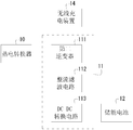
- an embodiment of the present invention provides an intelligent thermal energy recovery and utilization device 100 , including a thermoelectric converter 10 , a DC conversion unit 11 , an energy storage battery 12 , and a first inverter 13 .
- thermoelectric converter 10 is disposed on a heat dissipation surface of the refrigeration device 20 for converting thermal energy into a first direct current.
- the refrigeration device 20 may be an air conditioner, a refrigerator, a wine cabinet, and other refrigeration devices 20, as shown in FIG. 3 and FIG. 4, in one example of the present invention, the thermoelectric converter 10 may be attached to the back of the air conditioner and the air conditioner. The relative position of the inner capillary.
- the thermoelectric converter 10 can also be disposed at other locations, such as the side of the air conditioner, etc. position.
- thermoelectric converter 10 is mounted on the heat dissipating surface of the refrigerating apparatus 20, and converts heat radiated from the heat dissipating surface into electric energy.
- the thermoelectric converter 10 can employ a thermopile structure.
- the DC conversion unit 11 is connected to the thermoelectric converter 10 for converting the first DC voltage to the second DC power. That is, the thermoelectric converter 10 forms a lower voltage of the first direct current, and the first direct current of the low voltage is converted into the second direct current of the higher voltage by the direct current converting unit 11. For example, the thermoelectric converter 10 converts the voltage at which the first direct current is formed to 5 V, and the voltage converted to the formed second direct current by the direct current converting unit 11 is 24V.
- the energy storage battery 12 is connected to the DC conversion power source for storing the second DC power and outputting a third DC power. That is, the energy storage battery 12 can store the second direct current output from the direct current conversion unit 11. At the same time, the energy storage battery 12 outputs a third direct current when it is necessary to supply power to the device.
- the energy storage battery 12 can adopt a high-energy lithium battery or the like, and the high-energy lithium battery has a high specific energy, and the high-energy lithium battery can store more electric energy, and the use is long.
- the first inverter 13 is connected to the energy storage battery 12 for converting the third direct current into a first alternating current and supplying the first alternating current output to the refrigeration device 20. That is to say, the electric energy stored in the energy storage battery 12 can be supplied to the refrigeration device 20 after being inverted.
- the thermoelectric converter 10 can be used to convert the thermal energy emitted by the refrigeration device 20 into a first direct current, and the first direct current is boosted and converted into a second direct current by the direct current conversion unit 11. It is stored in the energy storage battery 12 again.
- the energy storage battery 12 can output a third direct current when needed, convert it into a first alternating current through the first inverter 13, and output it to the refrigeration device 20.
- the power generated by the recycling is used to supply power to the refrigeration device 20, which can reduce the power consumption of the refrigeration device 20 and achieve the purpose of energy saving and environmental protection.
- the surrounding environment can be prevented from being affected by the heat of the cooling device 20, and the quality of the environment in which the refrigeration device 20 is located can be improved.
- a wireless charging device 14 is further disposed.
- the wireless charging device 14 is disposed on a bottom surface or a side surface of the refrigeration device 20, and is coupled to the DC conversion unit. 11 connected to receive wirelessly transmitted power.
- the DC conversion unit 11 is further configured to convert the electrical energy into a fourth direct current
- the energy storage battery 12 is further configured to store the fourth direct current.
- the wireless charging device 14 is mounted on the refrigeration device 20, and the energy storage battery 12 can be charged by the wireless charging device 14. Specifically, the electrical energy received by the wireless charging device 14 is first converted into a high voltage by the DC conversion unit 11. The fourth direct current is stored in the energy storage battery 12. In this way, it can be ensured that the energy storage battery 12 can When the power is saturated, when the power grid is powered off, the energy storage battery 12 can be effectively utilized to supply power to the refrigeration device 20, thereby ensuring that the food or articles stored in the refrigeration device 20 are not deteriorated due to power outages.
- the DC conversion unit 11 includes a second inverter 111, a rectification filter circuit 112, and a DC-DC conversion circuit 113.
- the second inverter 111 is connected to the thermoelectric converter and the wireless charging device 14 for converting the first direct current into the second alternating current or converting the electrical energy into the third alternating current.
- the rectifying and filtering circuit 112 is connected to the second inverter 111 for converting the second alternating current into a first low voltage direct current or converting the third alternating current into a second low voltage direct current.
- the DC-DC conversion circuit 113 is connected to the rectification and filtering circuit 112 for boosting the first low-voltage DC power to form the second DC power, or boosting the second low-voltage DC power to form the fourth DC power.
- the first direct current output by the thermoelectric converter 10 or the electric energy output by the wireless charging device 14 is first converted into alternating current by the second inverter 111, and then formed and filtered by the rectifying and filtering circuit 112 to form a low-voltage direct current. Finally, the low-voltage direct current is converted into a high-voltage direct current through the DC-DC conversion circuit 113.
- the DC converter unit 11 can ensure that the second DC power and the fourth DC power formed by the conversion are more stable.
- a heat transfer device 15 is further disposed, the heat transfer device 15 is attached to a heat dissipation surface of the refrigeration device 20, and the hot end of the thermoelectric converter 10 is attached to The heat transfer device 15.
- the heat transfer device 15 is attached to the back surface of the refrigeration unit 20, and the hot end of the thermoelectric converter 10 is attached to the heat transfer device 15.
- the heat of the refrigeration device 20 can be quickly conducted to the hot end of the thermoelectric converter 10 through the heat conduction device 15, thereby ensuring that the hot end of the thermoelectric converter 10 has a higher temperature.
- the temperature difference between the hot end and the cold end of the thermoelectric converter 10 can be increased, and the greater the temperature difference, the greater the electric energy generated, that is, the higher the voltage of the first direct current formed by the conversion. That is, the conversion efficiency of the thermoelectric converter 10 is improved.
- the heat transfer device 15 includes a first hollow heat conducting plate 151, a second hollow heat conducting plate 152, a third hollow heat conducting plate 153, and a phase change medium.
- first hollow heat conducting plate 151 is horizontally disposed, and the hot end of the thermoelectric converter 10 is attached to the first hollow heat conducting plate 151.
- the second hollow heat conducting plate 152 is vertically disposed and attached to the heat dissipating surface of the refrigeration device 20 .
- a plurality of third hollow heat conducting plates 153 are obliquely disposed between the first hollow heat conducting plate 151 and the second hollow heat conducting plate 152, and an upper end of each of the third hollow heat conducting plates 153 and the first hollow heat conducting plate 151 is connected to each other, and a lower end of each of the third hollow heat conducting plates 153 is in communication with the second hollow heat conducting plate 152 to connect the first, second and third hollow heat conducting plates 151, 152, 153 Form a dielectric loop.
- the third hollow heat conducting plate 153 and the first A hollow heat conducting plate 151 and a second hollow heat conducting plate 152 form a triangular structure.
- a phase change medium is filled in the medium circuit and configured to change from a liquid state to a vapor state when the temperature is greater than a predetermined value.
- the second hollow heat conducting plate 152 absorbs the heat of the refrigeration device 20, and the internal phase change medium absorbs heat into a vapor state, and the vapor phase change medium rises to the first hollow through the plurality of third hollow heat conducting plates 153.
- the heat conducting plate 151 in the direction indicated by the arrow in the figure, the high temperature vapor phase change medium transfers heat to the first hollow heat conducting plate 151, and the first hollow heat conducting plate 151 quickly conducts the temperature to the hot end of the thermoelectric converter 10 Therefore, after the first hollow heat conducting plate 151 exchanges heat with the thermoelectric converter 10, the temperature thereof is lowered.
- thermoelectric converter 10 Since the temperature of the first hollow heat conducting plate 151 is lowered, the vapor phase variable medium is recondensed into a liquid state. And falling freely under the action of gravity, falling into the second hollow heat conducting plate 152 via the plurality of third hollow heat conducting plates 153, and circulating, the heat can be quickly transferred to the hot end of the thermoelectric converter 10, so that the thermoelectric converter 10 The thermal energy at the hot end is concentrated to reach a higher temperature, thereby causing a larger temperature difference between the hot end and the cold end of the thermoelectric converter 10, and finally, the conversion efficiency of the thermoelectric converter 10 is improved.
- thermoelectric converter 10 the conversion efficiency of the thermoelectric converter 10 is low, and thus the general application thereof is affected.
- the heat of the refrigeration device 20 can be quickly The transfer to the hot end of the thermoelectric converter 10 allows the thermoelectric converter 10 to reach a higher temperature per unit time, thus improving the conversion efficiency of the thermoelectric converter 10, ensuring its practicability and reliability.
- a plurality of the third hollow heat conducting plates 153 are equally spaced, between two adjacent third hollow heat conducting plates 153.
- a heat sink 154 is sandwiched. In this way, the heat transfer between the adjacent two third hollow heat conducting plates 153 is more rapid, so that the phase change medium inside thereof is disguised faster, and the heat energy transfer efficiency is further improved.
- the fins 154 are undulating, and the undulating fins 154 may increase the heat transfer area, thereby making the heat conduction between the third hollow heat conducting plates 153 more uniform and faster.
- the first, second and third hollow thermally conductive plates 151, 152, 153 are filled with a foamed metal or metal fiber sintered felt. Since the foamed metal or metal fiber sintered felt has a mesh-like structure, the phase-change medium can penetrate into the mesh-like structure, and the phase-change medium has a larger contact area with the foamed metal or metal fiber sintered felt, first and second. After the temperature of the third hollow heat conducting plate 151, 152, 153 is transmitted to the foam metal or metal fiber sintered felt in the interior thereof, it can be quickly transferred to the phase change medium, thereby causing the phase change medium to rapidly heat up and disguise to form a vapor state. Thereby, the heat transfer efficiency can be further improved, thereby further improving the conversion efficiency of the thermoelectric converter 10.
- a cooling device (not shown) is further provided, the cooling device being disposed at a cold end of the thermoelectric converter 10 for absorbing heat of the cold end of the thermoelectric converter 10. That is, in the thermoelectric converter The cold end of 10 is provided with a cooling device, by which the cold end of the thermoelectric converter 10 can be rapidly cooled, thereby further increasing the temperature between the hot end and the cold end of the thermoelectric converter 10, thereby further improving the thermoelectric converter. 10 conversion efficiency.
- the cooling device can adopt a structure such as a cooling fan, a water-cooled heat exchange coil, and the like.
- thermoelectric converter 10 can achieve higher conversion efficiency, and the heat energy of the recovery refrigeration device 20 can be utilized to the utmost extent, and the utility and reliability are further improved. high.
- An embodiment of the present invention provides an air conditioning system including an air conditioner and a thermal energy recovery device 100 of the refrigeration device 20 as described above, wherein the thermoelectric converter 10 of the smart thermal energy recovery device 100 is disposed in the air conditioner. Cooling surface.
- the heat energy of the air conditioner can be recycled.
- using the electric energy generated by the recycling to supply power to the air conditioner can reduce the power consumption of the air conditioner and achieve the purpose of energy saving and environmental protection.
- the surrounding environment can be prevented from being affected by the heat of the air conditioner, thereby improving the quality of the environment in which the air conditioner is located.
Abstract
La présente invention concerne un appareil de recyclage d'énergie thermique intelligent et un système de climatisation, l'appareil de recyclage d'énergie thermique (100) comprenant un convertisseur thermoélectrique (10), une unité de conversion de courant continu (11), une batterie de stockage d'énergie (12) et un premier onduleur (13), le convertisseur thermoélectrique (10) étant agencé sur une face de dissipation thermique d'un dispositif de réfrigération (20) et étant utilisé pour convertir l'énergie thermique en un premier courant continu; l'unité de conversion de courant continu (11) est connectée au convertisseur thermoélectrique (10) et est utilisée pour effectuer une conversion de tension d'amplification sur le premier courant continu pour convertir celui-ci en un deuxième courant continu; la batterie de stockage d'énergie (12) est connectée à l'unité de conversion de courant continu (11), et est utilisée pour stocker le deuxième courant continu et délivrer en sortie un troisième courant continu; et le premier onduleur (13) est connecté à la batterie de stockage d'énergie (12), et est utilisé pour convertir le troisième courant continu en un premier courant alternatif et pour transmettre le premier courant alternatif au dispositif de réfrigération (20). Au moyen de l'appareil, l'énergie thermique du dispositif de réfrigération peut être recyclée. En outre, l'énergie électrique formée par le recyclage est utilisée pour fournir de l'énergie à un dispositif de réfrigération, la consommation d'énergie électrique du dispositif de réfrigération peut être réduite, et les objectifs de conservation d'énergie et de protection de l'environnement peuvent être atteints.
Applications Claiming Priority (2)
| Application Number | Priority Date | Filing Date | Title |
|---|---|---|---|
| CN201610345377.XA CN105846531B (zh) | 2016-05-20 | 2016-05-20 | 智能热能回收利用装置及空调系统 |
| CN201610345377.X | 2016-05-20 |
Publications (1)
| Publication Number | Publication Date |
|---|---|
| WO2017197842A1 true WO2017197842A1 (fr) | 2017-11-23 |
Family
ID=56594090
Family Applications (1)
| Application Number | Title | Priority Date | Filing Date |
|---|---|---|---|
| PCT/CN2016/103676 WO2017197842A1 (fr) | 2016-05-20 | 2016-10-28 | Appareil de recyclage d'énergie thermique intelligent et système de climatisation |
Country Status (2)
| Country | Link |
|---|---|
| CN (1) | CN105846531B (fr) |
| WO (1) | WO2017197842A1 (fr) |
Cited By (5)
| Publication number | Priority date | Publication date | Assignee | Title |
|---|---|---|---|---|
| CN109633955A (zh) * | 2018-11-23 | 2019-04-16 | 重庆天胜科技有限公司 | 一种具有边缘自动恢复功能的液晶屏 |
| CN110332619A (zh) * | 2019-07-01 | 2019-10-15 | 江苏盖德冷冻机有限公司 | 一种空调冷凝器节能控制装置及其控制方法 |
| CN114336916A (zh) * | 2020-09-30 | 2022-04-12 | 西安西电高压开关有限责任公司 | 一种gis用采集器供电系统 |
| US11627834B2 (en) | 2017-08-09 | 2023-04-18 | Sharkninja Operating Llc | Cooking system for cooking food |
| US11751722B2 (en) | 2019-02-25 | 2023-09-12 | Sharkninja Operating Llc | Cooking device and components thereof |
Families Citing this family (6)
| Publication number | Priority date | Publication date | Assignee | Title |
|---|---|---|---|---|
| CN105846531B (zh) * | 2016-05-20 | 2019-08-23 | 广东百事泰电子商务股份有限公司 | 智能热能回收利用装置及空调系统 |
| CN107171596B (zh) * | 2017-05-17 | 2019-03-29 | 西北工业大学 | 一种基于塞贝克效应的红外抑制装置及其抑制方法 |
| CN111853964B (zh) * | 2019-04-24 | 2021-09-21 | 重庆海尔空调器有限公司 | 空调器 |
| CN110071662B (zh) * | 2019-04-29 | 2020-08-04 | 华中科技大学 | 一种利用泡沫金属回收余热的温差发电装置 |
| CN110925064A (zh) * | 2019-12-03 | 2020-03-27 | 安徽江淮汽车集团股份有限公司 | 尾气热能系统回收装置和车辆 |
| CN111916866B (zh) * | 2020-07-27 | 2021-06-29 | 东方醒狮(福建)储能科技有限公司 | 一种储能车及其控制方法 |
Citations (9)
| Publication number | Priority date | Publication date | Assignee | Title |
|---|---|---|---|---|
| CN1812247A (zh) * | 2005-01-26 | 2006-08-02 | 戴开煌 | 致冷或致热并带温差发电的装置 |
| US20100072943A1 (en) * | 2008-09-25 | 2010-03-25 | Energy Recovery Technology, Llc | Vehicle energy recovery system |
| CN203423164U (zh) * | 2013-06-05 | 2014-02-05 | 张剑锋 | 均温超导散热器 |
| CN103887897A (zh) * | 2014-03-10 | 2014-06-25 | 四川长虹电器股份有限公司 | 一种无线供电的冰箱及其工作方法 |
| CN104253565A (zh) * | 2014-10-09 | 2014-12-31 | 成都中环资(集团)有限公司 | 一种空调废热废能发电装置 |
| CN204612090U (zh) * | 2015-01-30 | 2015-09-02 | 郑州轻工业学院 | 一种利用压缩机余热进行温差发电的空调机 |
| CN105024591A (zh) * | 2015-08-10 | 2015-11-04 | 珠海格力电器股份有限公司 | 一种利用温差发电的系统及方法 |
| CN105846531A (zh) * | 2016-05-20 | 2016-08-10 | 广东百事泰电子商务股份有限公司 | 智能热能回收利用装置及空调系统 |
| CN205610312U (zh) * | 2016-05-20 | 2016-09-28 | 广东百事泰电子商务股份有限公司 | 智能热能回收利用装置及空调系统 |
Family Cites Families (3)
| Publication number | Priority date | Publication date | Assignee | Title |
|---|---|---|---|---|
| JP2012007778A (ja) * | 2010-06-23 | 2012-01-12 | Komatsu Ltd | 熱交換器 |
| CN204100404U (zh) * | 2014-09-14 | 2015-01-14 | 深圳市沃森空调技术有限公司 | 可无线充电的空调器 |
| CN104279678A (zh) * | 2014-10-29 | 2015-01-14 | 广东志高空调有限公司 | 一种具有废热回收功能的空调器 |
-
2016
- 2016-05-20 CN CN201610345377.XA patent/CN105846531B/zh active Active
- 2016-10-28 WO PCT/CN2016/103676 patent/WO2017197842A1/fr active Application Filing
Patent Citations (9)
| Publication number | Priority date | Publication date | Assignee | Title |
|---|---|---|---|---|
| CN1812247A (zh) * | 2005-01-26 | 2006-08-02 | 戴开煌 | 致冷或致热并带温差发电的装置 |
| US20100072943A1 (en) * | 2008-09-25 | 2010-03-25 | Energy Recovery Technology, Llc | Vehicle energy recovery system |
| CN203423164U (zh) * | 2013-06-05 | 2014-02-05 | 张剑锋 | 均温超导散热器 |
| CN103887897A (zh) * | 2014-03-10 | 2014-06-25 | 四川长虹电器股份有限公司 | 一种无线供电的冰箱及其工作方法 |
| CN104253565A (zh) * | 2014-10-09 | 2014-12-31 | 成都中环资(集团)有限公司 | 一种空调废热废能发电装置 |
| CN204612090U (zh) * | 2015-01-30 | 2015-09-02 | 郑州轻工业学院 | 一种利用压缩机余热进行温差发电的空调机 |
| CN105024591A (zh) * | 2015-08-10 | 2015-11-04 | 珠海格力电器股份有限公司 | 一种利用温差发电的系统及方法 |
| CN105846531A (zh) * | 2016-05-20 | 2016-08-10 | 广东百事泰电子商务股份有限公司 | 智能热能回收利用装置及空调系统 |
| CN205610312U (zh) * | 2016-05-20 | 2016-09-28 | 广东百事泰电子商务股份有限公司 | 智能热能回收利用装置及空调系统 |
Cited By (7)
| Publication number | Priority date | Publication date | Assignee | Title |
|---|---|---|---|---|
| US11627834B2 (en) | 2017-08-09 | 2023-04-18 | Sharkninja Operating Llc | Cooking system for cooking food |
| CN109633955A (zh) * | 2018-11-23 | 2019-04-16 | 重庆天胜科技有限公司 | 一种具有边缘自动恢复功能的液晶屏 |
| CN109633955B (zh) * | 2018-11-23 | 2023-09-29 | 深圳市博纳森光电有限公司 | 一种具有边缘自动恢复功能的液晶屏 |
| US11751722B2 (en) | 2019-02-25 | 2023-09-12 | Sharkninja Operating Llc | Cooking device and components thereof |
| US11766152B2 (en) | 2019-02-25 | 2023-09-26 | Sharkninja Operating Llc | Cooking device and components thereof |
| CN110332619A (zh) * | 2019-07-01 | 2019-10-15 | 江苏盖德冷冻机有限公司 | 一种空调冷凝器节能控制装置及其控制方法 |
| CN114336916A (zh) * | 2020-09-30 | 2022-04-12 | 西安西电高压开关有限责任公司 | 一种gis用采集器供电系统 |
Also Published As
| Publication number | Publication date |
|---|---|
| CN105846531A (zh) | 2016-08-10 |
| CN105846531B (zh) | 2019-08-23 |
Similar Documents
| Publication | Publication Date | Title |
|---|---|---|
| WO2017197842A1 (fr) | Appareil de recyclage d'énergie thermique intelligent et système de climatisation | |
| CN204612090U (zh) | 一种利用压缩机余热进行温差发电的空调机 | |
| JP3118240U (ja) | 半導体冷暖用電気器具 | |
| CN106486719A (zh) | 一种基于半导体制冷片的动力电池热管理系统 | |
| CN104279678A (zh) | 一种具有废热回收功能的空调器 | |
| CN101865557A (zh) | 制冷制热装置、以及带所述装置的杯子 | |
| CN106931573A (zh) | 模块化便携式半导体空调 | |
| CN102573420B (zh) | 一种嵌入式机柜空调制冷系统 | |
| US20130174580A1 (en) | Household System with Multiple Peltier Systems | |
| CN105932525B (zh) | 一种便携式激光冷却及供电装置 | |
| CN107131699A (zh) | 蓄冷式半导体制冷冰箱 | |
| CN102299614A (zh) | 一种基于半导体制冷的逆变器散热系统 | |
| Rokde et al. | Peltier based eco-friendly smart refrigerator for rural areas | |
| KR20130047118A (ko) | 열전시스템이 적용된 통신용 옥외 함체 | |
| CN106766494A (zh) | 太阳能温差发电移动冰箱 | |
| CN205718139U (zh) | 一种便携式太阳能制冷箱 | |
| CN106524631A (zh) | 组合式半导体制冷冰箱 | |
| CN105783366A (zh) | 一种便携式太阳能制冷箱 | |
| CN206895115U (zh) | 一种电子通讯设备的散热器 | |
| CN206449955U (zh) | 组合式半导体制冷冰箱 | |
| CN206322817U (zh) | 一种基于半导体制冷片的动力电池热管理系统 | |
| KR102283829B1 (ko) | 주름형 냉각핀 기반 에너지저장시스템 | |
| CN202066620U (zh) | 轻型半导体制冷的温度标定设备 | |
| CN207230799U (zh) | 半导体空调模组 | |
| CN201697390U (zh) | 制冷制热装置、以及带所述装置的杯子 |
Legal Events
| Date | Code | Title | Description |
|---|---|---|---|
| NENP | Non-entry into the national phase |
Ref country code: DE |
|
| 121 | Ep: the epo has been informed by wipo that ep was designated in this application |
Ref document number: 16902221 Country of ref document: EP Kind code of ref document: A1 |
|
| 122 | Ep: pct application non-entry in european phase |
Ref document number: 16902221 Country of ref document: EP Kind code of ref document: A1 |