WO2017195632A1 - メッシュ式ネブライザおよび交換部材 - Google Patents
メッシュ式ネブライザおよび交換部材 Download PDFInfo
- Publication number
- WO2017195632A1 WO2017195632A1 PCT/JP2017/016772 JP2017016772W WO2017195632A1 WO 2017195632 A1 WO2017195632 A1 WO 2017195632A1 JP 2017016772 W JP2017016772 W JP 2017016772W WO 2017195632 A1 WO2017195632 A1 WO 2017195632A1
- Authority
- WO
- WIPO (PCT)
- Prior art keywords
- main body
- mesh
- replacement member
- nebulizer
- side wall
- Prior art date
- Legal status (The legal status is an assumption and is not a legal conclusion. Google has not performed a legal analysis and makes no representation as to the accuracy of the status listed.)
- Ceased
Links
Images


Classifications
-
- A—HUMAN NECESSITIES
- A61—MEDICAL OR VETERINARY SCIENCE; HYGIENE
- A61M—DEVICES FOR INTRODUCING MEDIA INTO, OR ONTO, THE BODY; DEVICES FOR TRANSDUCING BODY MEDIA OR FOR TAKING MEDIA FROM THE BODY; DEVICES FOR PRODUCING OR ENDING SLEEP OR STUPOR
- A61M11/00—Sprayers or atomisers specially adapted for therapeutic purposes
- A61M11/005—Sprayers or atomisers specially adapted for therapeutic purposes using ultrasonics
-
- A—HUMAN NECESSITIES
- A61—MEDICAL OR VETERINARY SCIENCE; HYGIENE
- A61M—DEVICES FOR INTRODUCING MEDIA INTO, OR ONTO, THE BODY; DEVICES FOR TRANSDUCING BODY MEDIA OR FOR TAKING MEDIA FROM THE BODY; DEVICES FOR PRODUCING OR ENDING SLEEP OR STUPOR
- A61M11/00—Sprayers or atomisers specially adapted for therapeutic purposes
-
- A—HUMAN NECESSITIES
- A61—MEDICAL OR VETERINARY SCIENCE; HYGIENE
- A61M—DEVICES FOR INTRODUCING MEDIA INTO, OR ONTO, THE BODY; DEVICES FOR TRANSDUCING BODY MEDIA OR FOR TAKING MEDIA FROM THE BODY; DEVICES FOR PRODUCING OR ENDING SLEEP OR STUPOR
- A61M15/00—Inhalators
- A61M15/0085—Inhalators using ultrasonics
-
- B—PERFORMING OPERATIONS; TRANSPORTING
- B05—SPRAYING OR ATOMISING IN GENERAL; APPLYING FLUENT MATERIALS TO SURFACES, IN GENERAL
- B05B—SPRAYING APPARATUS; ATOMISING APPARATUS; NOZZLES
- B05B17/00—Apparatus for spraying or atomising liquids or other fluent materials, not covered by the preceding groups
- B05B17/04—Apparatus for spraying or atomising liquids or other fluent materials, not covered by the preceding groups operating with special methods
- B05B17/06—Apparatus for spraying or atomising liquids or other fluent materials, not covered by the preceding groups operating with special methods using ultrasonic or other kinds of vibrations
- B05B17/0607—Apparatus for spraying or atomising liquids or other fluent materials, not covered by the preceding groups operating with special methods using ultrasonic or other kinds of vibrations generated by electrical means, e.g. piezoelectric transducers
- B05B17/0623—Apparatus for spraying or atomising liquids or other fluent materials, not covered by the preceding groups operating with special methods using ultrasonic or other kinds of vibrations generated by electrical means, e.g. piezoelectric transducers coupled with a vibrating horn
- B05B17/063—Apparatus for spraying or atomising liquids or other fluent materials, not covered by the preceding groups operating with special methods using ultrasonic or other kinds of vibrations generated by electrical means, e.g. piezoelectric transducers coupled with a vibrating horn having an internal channel for supplying the liquid or other fluent material
-
- B—PERFORMING OPERATIONS; TRANSPORTING
- B05—SPRAYING OR ATOMISING IN GENERAL; APPLYING FLUENT MATERIALS TO SURFACES, IN GENERAL
- B05B—SPRAYING APPARATUS; ATOMISING APPARATUS; NOZZLES
- B05B17/00—Apparatus for spraying or atomising liquids or other fluent materials, not covered by the preceding groups
- B05B17/04—Apparatus for spraying or atomising liquids or other fluent materials, not covered by the preceding groups operating with special methods
- B05B17/06—Apparatus for spraying or atomising liquids or other fluent materials, not covered by the preceding groups operating with special methods using ultrasonic or other kinds of vibrations
- B05B17/0607—Apparatus for spraying or atomising liquids or other fluent materials, not covered by the preceding groups operating with special methods using ultrasonic or other kinds of vibrations generated by electrical means, e.g. piezoelectric transducers
- B05B17/0638—Apparatus for spraying or atomising liquids or other fluent materials, not covered by the preceding groups operating with special methods using ultrasonic or other kinds of vibrations generated by electrical means, e.g. piezoelectric transducers spray being produced by discharging the liquid or other fluent material through a plate comprising a plurality of orifices
- B05B17/0646—Vibrating plates, i.e. plates being directly subjected to the vibrations, e.g. having a piezoelectric transducer attached thereto
-
- A—HUMAN NECESSITIES
- A61—MEDICAL OR VETERINARY SCIENCE; HYGIENE
- A61M—DEVICES FOR INTRODUCING MEDIA INTO, OR ONTO, THE BODY; DEVICES FOR TRANSDUCING BODY MEDIA OR FOR TAKING MEDIA FROM THE BODY; DEVICES FOR PRODUCING OR ENDING SLEEP OR STUPOR
- A61M15/00—Inhalators
- A61M15/0001—Details of inhalators; Constructional features thereof
- A61M15/0021—Mouthpieces therefor
-
- A—HUMAN NECESSITIES
- A61—MEDICAL OR VETERINARY SCIENCE; HYGIENE
- A61M—DEVICES FOR INTRODUCING MEDIA INTO, OR ONTO, THE BODY; DEVICES FOR TRANSDUCING BODY MEDIA OR FOR TAKING MEDIA FROM THE BODY; DEVICES FOR PRODUCING OR ENDING SLEEP OR STUPOR
- A61M2205/00—General characteristics of the apparatus
- A61M2205/82—Internal energy supply devices
- A61M2205/8206—Internal energy supply devices battery-operated
Definitions
- the present invention relates to a mesh type nebulizer, and more particularly to a mesh type nebulizer that atomizes a liquid supplied between a vibrating surface and a mesh portion and ejects the liquid through the mesh portion.
- the present invention also relates to an exchange member used to construct such a mesh nebulizer.
- the main body is provided with a horn vibrator, and can be attached to and detached from the main body and can be opened and closed (rotated). It is known to have a mesh cap that can be moved).
- the vibration surface of the horn vibrator faces the mesh portion of the mesh cap.
- a chemical solution is supplied between the vibration surface and the mesh portion, and a driving voltage is applied to the horn vibrator to vibrate the vibration surface.
- medical solution is atomized through the said mesh part, and it ejects.
- the mesh type nebulizer it is necessary to remove the mesh cap from the main body each time after use, and to wash, disinfect, and dry the mesh cap including the mesh portion. For this reason, there is a problem that care is troublesome for the user. Further, since the mesh cap including the mesh portion is a consumable part, it is usually necessary to replace the mesh cap within about one year even if the user properly cares for it. Since the mesh cap is relatively large and expensive, there is a problem that the cost burden for the replacement member is large for the user. In addition, if the mesh cap is not properly cleaned, the spray efficiency is lowered and unsanitary. Moreover, since the mesh cap is a precision part, it is difficult to clean.
- an object of the present invention is to provide a mesh type nebulizer that is easy for the user and requires less cost for replacement members.
- an object of the present invention is to provide an exchange member used for constructing such a mesh nebulizer.
- the mesh nebulizer of the present invention is A mesh type nebulizer that atomizes and ejects liquid through the mesh part, A main body having a concave portion opened upward;
- the main body A vibrating portion having a vibrating surface disposed at a position corresponding to the bottom surface of the recess;
- a liquid supply unit that supplies liquid toward the vibration surface of the vibration unit,
- a cap member that covers the upper part of the main body so as to be openable and closable;
- the replacement member includes a film-like mesh portion that should face the vibration surface, a bottom plate portion that supports the periphery of the mesh portion, a side wall portion that continues to the outer edge of the bottom plate portion and should face the side surface of the recess.
- the protruding portion that protrudes toward the main body side of the cap member presses the bottom plate portion of the replacement member toward the bottom surface of the recess, and
- the replacement member is positioned with respect to the longitudinal direction of the main body.
- the “film-like mesh portion” means an element for having a plurality of through holes penetrating the film and atomizing the liquid through the through holes.
- the planar shape of the concave portion widely includes an annular shape such as a circle and a rounded square (a square with rounded corners).
- the “vertical direction” of the main body means the vertical direction in general.
- the user who intends to use the mesh type nebulizer of the present invention can attach and detach the replacement member having the mesh portion to the concave portion opened upward from the main body with the cap member open to the main body. Installing. Thereby, the bottom plate portion (supporting the periphery of the mesh portion) of the replacement member faces the bottom surface of the recess, and the side wall portion of the replacement member faces the side surface of the recess. In this mounted state, the user closes the cap member with respect to the main body. Then, the protrusion provided on the main body side of the cap member presses the bottom plate portion of the replacement member toward the bottom surface of the recess to position the replacement member with respect to the longitudinal direction of the main body. To do.
- the mesh part of the said replacement member is positioned facing the vibration surface of the said vibration part distribute
- the mesh nebulizer can be easily assembled (this state is referred to as an assembled state).
- the liquid supply part supplies liquid toward the vibration surface of the vibration part. Thereby, a liquid is supplied between the vibration surface and the mesh part. And a drive voltage is applied to the said vibration part, and a vibration surface is vibrated. Thereby, the liquid is atomized and ejected through the mesh portion (more precisely, a plurality of through holes penetrating the film).
- the user opens the cap member with respect to the main body and removes the replacement member from the recess.
- the replacement member is typically disposable. In that case, the user does not need to clean, disinfect, and dry the replacement member including the mesh portion. Therefore, care is easy for the user. Further, since the replacement member is configured to be separated from the main body and the cap member, it can be relatively small and manufactured at low cost. Therefore, the cost burden for the replacement member can be reduced for the user.
- the side surface of the concave portion of the main body is gradually opened upward,
- the side wall portion of the replacement member is gradually opened toward the upper side so as to correspond to the side surface of the concave portion of the main body.
- the side surface of the concave portion of the main body is gradually opened upward. Therefore, when the user places the replacement member around the recess when the replacement member is mounted, the side wall portion of the replacement member is guided by the side surface of the recess, and the bottom plate portion (mesh of the replacement member) Supporting the periphery of the portion) is opposed to the bottom surface of the recess, and the side wall portion of the replacement member is opposed to the side surface of the recess. Therefore, the user can easily attach the replacement member to the recess of the main body.
- the replacement member includes a knob portion that is continuous with the upper edge of the side wall portion and extends radially in a specific direction around the center of the side wall portion. .
- the replacement member when the replacement member is mounted, the user holds the pick portion with his / her hand (for example, picks with the thumb and the index finger), so that the mesh portion of the replacement member is placed on the mesh portion.
- the replacement member can be easily mounted in the recess of the main body without touching with a finger.
- the user can easily remove the replacement member from the recess by holding the pick portion with his / her hand (eg, picking with the thumb and index finger).
- the mesh type nebulizer according to one embodiment is characterized in that the knob portion extends in opposite directions with respect to the center of the side wall portion.
- the replacement member when the replacement member is mounted, the user uses his / her hand (for example, thumb and forefinger) to place portions extending in the opposite directions of the knob portion on both sides. By pinching from the (outside) toward the center, the replacement member can be easily mounted in the concave portion of the main body without touching the mesh portion of the replacement member with a finger.
- the replacement member when the replacement member is mounted, the user is mounted with the other part of the hand holding the knob of the replacement member (for example, the little finger, the palm, etc.) in contact with the side surface of the main body. If it does, the position shift (blurring) of the hand with respect to the main body can be easily suppressed.
- the user can more easily attach the replacement member to the recess of the main body.
- the user sandwiches the portion extending in the opposite direction of the knob part from both sides (outside) toward the center with his / her hand (for example, thumb and forefinger), The replacement member can be easily removed from the recess.
- a groove extending radially from the recess to a specific orientation is formed around the upper edge of the recess in the main body so as to correspond to the knob portion of the replacement member. It is provided.
- the user aligns the knob of the replacement member with the groove around the upper edge of the recess, thereby Positioning in the circumferential direction is possible.
- the vibrating surface is arranged perpendicular to the longitudinal direction of the main body,
- the bottom surface of the concave portion of the main body is inclined with respect to the longitudinal direction of the main body,
- the mesh portion and the bottom plate portion of the replacement member are inclined with respect to the center of the side wall portion so as to correspond to the bottom surface of the concave portion of the main body.
- the bottom surface of the concave portion of the main body is inclined with respect to the longitudinal direction of the main body, and the replacement member so as to correspond to the bottom surface of the concave portion of the main body.
- the mesh portion and the bottom plate portion are inclined with respect to the center of the side wall portion. Therefore, if the user places the replacement member around the recess when the replacement member is mounted, the mesh portion and the bottom plate portion of the replacement member correspond to the bottom surface of the recess of the main body. Be guided to. Therefore, the positioning of the replacement member in the circumferential direction and the vertical axis direction with respect to the concave portion is assisted.
- the mesh portion is inclined and opposed to the vibration surface. Therefore, at the time of use, the part which has a suitable clearance gap with respect to the said vibration surface among the said mesh parts functions, and spraying of a liquid is performed effectively.
- the mesh type nebulizer according to one embodiment is characterized in that a packing is provided on the side surface of the concave portion of the main body so as to surround and contact the side wall portion of the replacement member in the circumferential direction.
- packing is provided on the side surface of the concave portion of the main body so as to surround and contact the side wall portion of the replacement member in the circumferential direction. Therefore, thanks to this packing, the liquid supplied between the vibrating surface and the mesh portion overflows to the outside through the gap between the side surface of the concave portion and the side wall portion of the replacement member. Can be prevented.
- the replacement member is made of a synthetic resin.
- the replacement member is made of synthetic resin. Therefore, the replacement member can be manufactured at a low cost.
- the cap member is rotatably connected to the main body via a hinge.
- the cap member is rotatably connected to the main body via a hinge. Therefore, the user can easily open and close the cap member with respect to the main body. Further, the cap member is not lost.
- the exchange member of the present invention is an exchange member used to configure the mesh nebulizer, A film-like mesh portion to be opposed to the vibration surface; A bottom plate portion supporting the periphery of the mesh portion; And a side wall portion that is continuous with the outer edge of the bottom plate portion and should face the side surface of the recess.
- the replacement member of the present invention is typically disposable after being used in the mesh nebulizer. In that case, the user does not need to clean, disinfect, and dry the replacement member including the mesh portion. Therefore, care is easy for the user. Further, since the replacement member is configured to be separated from the main body and the cap member, it can be relatively small and manufactured at low cost. Therefore, the cost burden for the replacement member can be reduced for the user.
- the replacement member includes a knob portion that is continuous with the upper edge of the side wall portion and extends radially in a specific direction around the center of the side wall portion.
- the user can touch the mesh portion of the replacement member with his / her finger by holding the pick portion with his / her hand (eg, picking with the thumb and forefinger).
- the replacement member can be easily mounted in the recess of the main body.
- the user can easily remove the replacement member from the recess by holding the pick portion with his / her hand (eg, picking with the thumb and index finger).
- the knob portion extends in opposite directions with respect to the center of the side wall portion.
- the replacement member of this embodiment When the replacement member of this embodiment is mounted, the user uses his / her hand (for example, thumb and forefinger) to place the portion of the knob that extends in the opposite direction from both sides (outside) to the center. By pinching in the direction, the replacement member can be easily mounted in the concave portion of the main body without touching the mesh portion of the replacement member with a finger.
- the user when the replacement member is mounted, the user is mounted with the other part of the hand holding the knob of the replacement member (for example, the little finger, the palm, etc.) in contact with the side surface of the main body. If it does, the position shift (blurring) of the hand with respect to the main body can be easily suppressed.
- the user can more easily attach the replacement member to the recess of the main body.
- the user sandwiches the portion extending in the opposite direction of the knob part from both sides (outside) toward the center with his / her hand (for example, thumb and forefinger), The replacement member can be easily removed from the recess.
- the mesh type nebulizer of the present invention is easy for the user to maintain and the cost for the replacement member is small.
- the replacement member of the present invention can be relatively small and manufactured at low cost. Therefore, the cost burden for the replacement member can be reduced for the user.
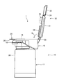
- FIG. 5A is a view showing a state where the mesh nebulizer is assembled (assembled state) as viewed from the right side.
- FIG. 5 (B) and 5 (C) are views showing the mesh type nebulizer of FIG. 5 (A) as viewed from the front and from above, respectively. It is a figure which shows the longitudinal cross-section when the mesh type nebulizer in an assembly state is seen from the right side. It is a figure which expands and shows the vicinity of the replacement member in FIG.
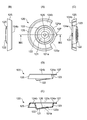
- FIG. 8A is a plan view showing the replacement member.
- FIGS. 8B, 8C, and 8D are views showing the replacement member as viewed from the left side, the right side, and the lower side in FIG. 8A, respectively.
- FIG. 8E is a cross-sectional view taken along the line VIIIE-VIIIE in FIG.
- FIG. 8F is an enlarged view showing the vicinity of the mesh portion in FIG.
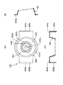
- FIG. 12A is a plan view showing the replacement member of the first modified example.
- 12 (B), 12 (C), and 12 (D) are views showing the replacement member of the first modified example as viewed from the left side, the right side, and the lower side in FIG. 12 (A), respectively.
- FIG. 12E is a view showing a cross section taken along line XIIE-XIIE in FIG.
- FIG. 13A is a plan view showing an exchange member of a second modification.
- FIG. 13B is a diagram showing a schematic cross section when the replacement member of the second modification is viewed from the right side in FIG.
- FIG. 14A is a plan view showing an exchange member of a third modification.
- FIG. 14B is a diagram showing a schematic cross-section when the replacement member of the third modified example is viewed from the right side in FIG.
- FIG. 15A is a plan view showing an exchange member of a fourth modification.
- FIGS. 15B and 15C are schematic cross-sectional views of the replacement member of the fourth modification when viewed from the right side and the lower side in FIG. 15A, respectively.
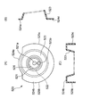
- FIG. 16A is a plan view showing an exchange member of a fifth modification.
- FIGS. 16B and 16C are schematic cross-sectional views of the replacement member of the fifth modification when viewed from the right side and the lower side in FIG. 16A, respectively.
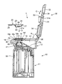
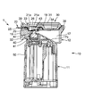
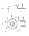
- FIG. 1 shows a mesh nebulizer according to an embodiment of the present invention (the whole is denoted by reference numeral 1) viewed obliquely in an exploded state.
- FIG. 2 shows a longitudinal section when the mesh nebulizer 1 in the exploded state of FIG. 1 is viewed from the right side (the direction indicated by the arrow A in FIG. 1).
- the mesh nebulizer 1 includes a main body lower portion 11 having a substantially quadrangular prism-like outer shape, and a substantially lower portion 11 that is detachably fitted to the main body lower portion 11 from above. And a main body upper part 12 having an elliptical columnar outer shape.
- the main body lower portion 11 and the main body upper portion 12 constitute a main body 10.
- a power switch 50 for turning on / off the power supply of the nebulizer 1 is provided on the front surface of the lower part 11 of the main body.
- LED lamps 51 and 52 for notifying the operation state of the nebulizer 1 are provided at the upper left corner and the upper right corner on the front side of the upper surface of the lower body 11, respectively.
- a control system, which will be described later, is mainly mounted inside the lower body 11.
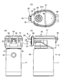
- a recess 16 having a substantially circular planar shape opened upward is provided in the front half of the upper surface of the main body upper portion 12 so as to receive an exchange member 20 described later.
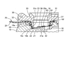
- the concave portion 16 has a bottom surface 16b inclined with respect to the longitudinal direction (vertical direction) of the main body 10, and a side surface 16c that is continuous with the bottom surface 16b and gradually opens upward. And have.
- a groove 16e is provided to extend to.
- grooves 16 f extending radially from the recess 16 to the rear side in this example are provided so as to correspond to a tip protrusion 27 of the replacement member 20 described later.
- a packing 29 is provided so as to surround and contact a side surface 16 c of the recess 16 of the main body 10 in a circumferential direction with a side wall 23 of the replacement member 20 described later.
- the vibration unit 40 includes an ultrasonic transducer 41 disposed at a position spaced downward from the recess 16, a vibration surface 43 disposed horizontally at a position corresponding to the bottom surface 16 b of the recess 16, and the ultrasonic transducer 41. And a horn 42 that amplifies the vibration of the ultrasonic transducer 41 and transmits it to the vibration surface 43.
- a driving voltage for the ultrasonic transducer 41 is supplied from the lower body 11 through a contact electrode provided between the upper body 12 and the lower body 11.
- a liquid storage portion 17 having a substantially semicircular planar shape is provided in a region corresponding to the latter half of the upper surface of the upper portion 12 of the main body.
- the liquid storage part 17 has a bottom surface 17 b that gradually becomes shallower toward the front side.
- a liquid supply path 18 for supplying a liquid (chemical solution) from the liquid storage unit 17 toward the vibration surface 43 of the vibration unit 40 is provided continuously to the front side portion of the liquid storage unit 17.
- the liquid storage part 17 and the liquid supply path 18 constitute a liquid supply part. In the disassembled state of FIGS. 1 and 2, the liquid storage unit 17 is open upward. Therefore, the user can put the chemical into the liquid storage unit 17 from above.
- a substantially oval plate-like cover 31 is coupled to the rear edge of the upper surface of the main body upper portion 12 so as to be rotatable with respect to the main body upper portion 12 via a hinge 38 as indicated by an arrow B. .
- the cover 31 has a protrusion 33 having a substantially cylindrical shape on the side facing the upper surface of the main body upper portion 12 and a mesa portion having a substantially semicircular planar shape corresponding to the planar shape of the liquid storage portion 17. 34.
- the protrusion 33 functions to position the replacement member 20.
- the mesa unit 34 blocks the upper part of the liquid storage unit 17 and prevents the liquid medicine from overflowing from the liquid storage unit 17.
- the cover 31 is rotatable with respect to the cover 31 via a hinge 39 as indicated by an arrow C, and is substantially U-shaped. Are connected.
- the engagement frame 32 is rotated toward the front surface of the main body upper portion 12 in a state in which the cover 31 is closed with respect to the main body upper portion 12, It is designed to engage. Thereby, the cover 31 can be fixed to the main body upper portion 12 in a closed state.
- the cover 31 and the engagement frame 32 constitute a cap member 30. With this configuration, the user can easily open and close the cap member 30 with respect to the main body 10 (main body upper portion 12). Further, the cap member 30 is not lost.
- FIG. 1 and 2 show an exchange member 20 configured separately from the main body 10 and the cap member 30.
- the replacement member 20 is detachably attached to the concave portion 16 of the main body upper portion 12 in advance when the nebulizer 1 is used.
- the replacement member 20 supports the flat film 21 to be opposed to the vibration surface 43 (see FIGS. 1 and 2) and the periphery of the film 21.
- a flange portion 24 that extends radially (outward in the radial direction) around the upper edge thereof.
- the film 21 is attached to the upper surface of the bottom plate portion 22 by adhesion or welding.
- a substantially central region of the film 21 forms a mesh portion 21a.
- FIG. 8F shows an enlarged view of the vicinity of the mesh portion 21a in FIG.
- a flat annular ring member 26 having a thickness of about 400 ⁇ m is attached to the position surrounding the mesh portion 21a on the film 21 by adhesion or welding. The ring member 26 is attached to keep the mesh portion 21a as flat as possible and adjust the natural frequency of the film 21 including the mesh portion 21a.
- the inner diameter ID of the ring member 26 is set to 2.2 mm, and the outer dimension OD is set to 6.0 mm.
- the mesh portion 21a is located in the opening 26o of the ring member 26 so that the atomized chemical liquid can be discharged through the above-described through hole.
- the mesh portion 21a and the bottom plate portion 22 of the replacement member 20 correspond to the center 23c of the side wall portion 23 so as to correspond to the bottom surface 16b (see FIG. 2) of the concave portion 16 of the main body 10. Is inclined. Moreover, the side wall part 23 of the replacement member 20 is gradually opened as it corresponds to the side surface 16c (refer FIG. 2) of the recessed part 16 of the main body 10 as it goes upwards.
- a protrusion 22p protrudes inward in the radial direction from the bottom plate portion 22, and reaches the position directly below the ring member 26 and stops.
- the grip 25 extends beyond the flange 24 and has a specific orientation with respect to the periphery of the center 23c of the side wall 23. (In this example, it extends radially to the left in FIGS. 8A and 8E).
- the knob 25 is provided for the convenience of picking up and down with the thumb and index finger, for example.
- the knob portion 25 is provided with unevenness 25p for preventing slipping.
- the tip protrusion 27 extends beyond the flange portion 24 in the opposite direction to the extension of the knob 25, and in this example, FIGS. 8A and 8E. Projecting to the right.
- the knob 25 and the tip protrusion 27 enable the positioning of the replacement member 20 in the circumferential direction with respect to the recess 16 when the user mounts the replacement member 20 in the recess 16 of the main body upper portion 12.
- all elements constituting the replacement member 20 are made of synthetic resin. Therefore, the replacement member 20 can be manufactured at low cost.
- Synthetic resins constituting the replacement member 20 include polyamide resin, polyester, syndiopolystyrene, polysulfone, polyethersulfone, polyetheretherketone, polyetherimide, polyamideimide, PPS (polyphenylene sulfide), epoxy, phenol, polyimide. Etc.
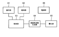
- FIG. 9 shows a block configuration of a control system mounted on the main body 10 of the mesh nebulizer 1.
- the mesh nebulizer 1 includes an operation unit 61, a notification unit 62, a control unit 63, an oscillation frequency generation unit 64, an atomization unit 65, and a power supply unit 66.
- the operation unit 61 includes the power switch 50 shown in FIG.
- the notification unit 62 includes the LED lamps 51 and 52 shown in FIG. 1, and may further include a buzzer (not shown).
- the oscillation frequency generation unit 64 applies an alternating drive voltage to the atomization unit 65 based on a control signal from the control unit 63. This drive voltage is output over a certain output time after the power switch 50 is pressed, for example.
- the output time can be measured by a timer (not shown).
- the atomization part 65 includes the vibration part 40 and the mesh part 21a of the replacement member 20 shown in FIG.
- the AC drive voltage from the oscillation frequency generation unit 64 is applied to the ultrasonic transducer 41 of the vibration unit 40 that forms the atomization unit 65.
- the vibration of the ultrasonic transducer 41 is amplified by the horn 42 and transmitted to the vibration surface 43.
- the vibration surface 43 vibrates, the chemical solution supplied to the gap between the vibration surface 43 and the mesh portion 21a is atomized and ejected through the mesh portion 21a.
- the control unit 63 includes a CPU (Central Processing Unit) and sends a signal to the atomization unit 65 via the oscillation frequency generation unit 64 to control the atomization amount, the continuous operation time, and the like. In addition, the control unit 63 notifies that the power is turned on when the LED lamp 51 is turned on, the battery capacity is insufficient due to the blinking of the LED lamp 52, and the like.
- the power supply unit 66 includes a battery (for example, a DC3V chargeable / dischargeable secondary battery), and supplies power to each unit of the control system.
- a user who intends to use the mesh nebulizer 1 has a concave portion 16 having a shape opened upward from the main body 10 with the cap member 30 open to the main body 10 as shown in FIGS. 1 and 2.
- the replacement member 20 having the mesh portion 21a is attached.
- the replacement member 20 When the replacement member 20 is mounted, the user holds the picking portion 25 with his / her hand (for example, pinching the picking portion 25 up and down with the thumb and the index finger) to the mesh portion 21 a of the replacement member 20.
- the replacement member 20 can be easily attached to the recess 16 of the main body 10 without touching with a finger.
- the user aligns the tip protrusion 27 and the knob 25 of the replacement member 20 with the groove 16f and the groove 16e around the upper edge of the recess 16, respectively. Positioning in the circumferential direction is possible.
- the side surface 16c of the concave portion 16 of the main body 10 gradually opens as it goes upward.
- the side wall part 23 of the replacement member 20 is gradually opened as it corresponds to the side surface 16c (refer FIG. 2) of the recessed part 16 of the main body 10 as it goes upwards. Therefore, if the user places the replacement member 20 around the recess 16 when the replacement member 20 is mounted, the side wall portion 23 of the replacement member 20 is guided downward by the side surface 16 c of the recess 16.
- the bottom surface 16b of the concave portion 16 of the main body 10 is inclined with respect to the longitudinal direction (vertical direction) of the main body 10, and the mesh of the replacement member 20 so as to correspond to the bottom surface 16b of the concave portion 16 of the main body 10.
- the part 21 a and the bottom plate part 22 are inclined with respect to the center 23 c of the side wall part 23. Therefore, if the user places the replacement member 20 around the recess 16 when the replacement member 20 is mounted, the mesh portion 21 a and the bottom plate portion 22 of the replacement member 20 correspond to the bottom surface 16 b of the recess 16 of the main body 10. To be guided. Therefore, positioning of the replacement member 20 in the circumferential direction and the vertical axis direction with respect to the recess 16 is assisted.
- the bottom plate portion 22 (supporting the periphery of the mesh portion 21 a) of the replacement member 20 faces the bottom surface 16 b of the recess 16, and the side wall portion 23 of the replacement member 20 is recessed. 16 faces the side surface 16c. Therefore, the user can easily attach the replacement member 20 to the recess 16 of the main body 10. This state is called a wearing state.
- the mesa part 34 of the cover 31 closes the upper part of the liquid storage part 17 and prevents the liquid medicine from overflowing from the liquid storage part 17.
- the protruding portion 33 that protrudes toward the main body upper portion 12 side of the cap member 30 is the bottom plate of the replacement member 20.
- the replacement member 20 is positioned with respect to the longitudinal direction of the main body 10 by pressing the portion 22 toward the bottom surface 16 b of the recess 16. Accordingly, the mesh portion 21a of the replacement member 20 is positioned to face the vibration surface 43 of the vibration portion 40 disposed at a position corresponding to the bottom surface 16b of the recess 16.
- the mesh portion 21a is inclined and opposed to the vibration surface 43. Therefore, at the time of use described below, the portion having an appropriate gap with respect to the vibration surface 43 of the mesh portion 21a functions, and the spraying of the chemical liquid is performed effectively.
- the packing 29 is provided so as to be in contact with the side surface 16c of the recess 16 of the main body 10 so as to surround the side wall portion 23 of the replacement member 20 in the circumferential direction. Therefore, thanks to the packing 29, the chemical solution supplied between the vibration surface 43 and the mesh portion 21 a can be used between the side surface 16 c of the concave portion 16 and the side wall portion 23 of the replacement member 20 in the following use. Can be prevented from overflowing to the outside.
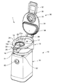
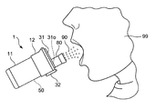
- the user When using the mesh nebulizer 1, the user puts a chemical solution in the liquid storage part 17 of the main body upper part 12 in advance. Then, as shown in FIG. 10, the user detachably attaches, for example, a mouthpiece 80 to the opening 31o in the protrusion 33 of the cover 31 in the assembled state. Instead of the mouthpiece 80, an inhalation mask that covers the face of the user 99 may be attached.
- the liquid medicine is supplied from the liquid storage part 17 constituting the liquid supply part through the liquid supply path 18 toward the vibration surface 43 of the vibration part 40. Is supplied. That is, the chemical solution is supplied between the vibration surface 43 and the mesh portion 21a.
- a driving voltage is applied to the ultrasonic transducer 41 of the vibrating unit 40 and the vibrating surface 43 is vibrated.
- medical solution 90 is atomized and ejected through the mesh part 21a (more precisely, the several through-hole which penetrates the film 21).
- the user After using the mesh nebulizer 1, the user removes the mouthpiece 80 and removes the upper body portion 12 from the lower body portion 11. Further, the cap member 30 is opened with respect to the upper portion 12 of the main body, and the replacement member 20 is removed from the recess 16. At this time, the user 99 can easily remove the replacement member 20 from the concave portion 16 by holding the pick portion 25 with his / her hand (for example, pinching the pick portion 25 with the thumb and the index finger). it can.
- the user tilts the upper part 12 of the main body and discharges the chemical solution remaining in the liquid storage unit 17.
- the mouthpiece 80 and the main body upper part 12 are cleaned, disinfected, and dried.
- the main body lower part 11 is also cleaned, disinfected, and dried as necessary.
- the replacement member 20 is typically disposable. In that case, the user does not need to clean, disinfect, and dry the replacement member 20 including the mesh portion 21a. Therefore, care is easy for the user. Moreover, since the replacement member 20 is configured separately from the main body 10 and the cap member 30 and is made of a synthetic resin, the replacement member 20 can be relatively small and manufactured at low cost. Therefore, the cost burden for the replacement member 20 can be reduced for the user.
- FIG. 11 shows the replacement member 120 of the first modified example viewed obliquely corresponding to the replacement member 20 in FIG. 12 (A) to 12 (E) show the replacement member 120 of the first modified example corresponding to FIGS. 8 (A) to 8 (E), respectively.
- 11 and 12A to 12E the reference numerals indicating the constituent elements of the replacement member 120 are each increased by 100 relative to the reference numerals indicating the corresponding constituent elements of the replacement member 20.
- the description which overlaps with the replacement member 20 is abbreviate
- the flange portion connected to the upper edge of the side wall portion 123 is divided into two portions 124a and 124b around the center 123c of the side wall portion 123.
- the flange portion 124a occupies an angle range of about 120 ° when viewed from the center 123c of the side wall portion 123 on the tip protrusion 127 side (right side) and extends radially.
- the flange portion 124b occupies an angular range of about 240 ° other than the flange portion 124a when viewed from the center 123c of the side wall portion 123, and extends radially.
- the radial dimension of the flange portion 124b is set larger than the radial dimension of the flange portion 124a.
- a skirt portion 125 as a knob portion is provided continuously with the outer edge of the flange portion 124b, instead of the knob portion 25 of the replacement member 20.
- the skirt portion 125 gradually opens as it goes downward, like a conical side surface, and substantially stops at the height of the bottom plate portion 122.
- the angle range of the skirt part 125 occupies about 240 degrees similarly to the angle range of the flange part 124b.
- the replacement member 120 When the replacement member 120 is mounted, the user uses his / her hand (for example, thumb and index finger) to indicate portions of the skirt portion 125 extending in opposite directions to each other, for example, by arrows G and H in FIG. As described above, by pinching from both sides (outside) toward the center, the replacement member 120 can be easily attached to the concave portion 16 of the main body upper portion 12 without touching the mesh portion 121a of the replacement member 120 with a finger. In particular, when the replacement member 120 is mounted, the user is mounted with the other part of the hand holding the skirt portion 125 of the replacement member 120 (for example, the little finger, the palm, etc.) in contact with the side surface of the main body 10.
- the user is mounted with the other part of the hand holding the skirt portion 125 of the replacement member 120 (for example, the little finger, the palm, etc.) in contact with the side surface of the main body 10.
- the position shift (shake) of the hand with respect to the main body 10 can be suppressed easily. Therefore, the user can more easily attach the replacement member 120 to the recess 16 of the main body upper portion 12. Further, after use, the user uses his / her hand (for example, thumb and forefinger) to place portions of the skirt portion 125 extending in opposite directions to each other as shown by arrows G and H in FIG. The replacement member 120 can be easily removed from the recess 16 by sandwiching from the (outside) toward the center.
- FIG. 13A shows the replacement member 220 of the second modification as viewed from above.
- FIG. 13B shows a schematic cross section of the replacement member 220 when viewed from the right side in FIG. 13A (for the sake of simplicity, a specific configuration in the vicinity of the mesh portion 221a is omitted, It is represented by a two-dot chain line).
- the reference numerals indicating the constituent elements of the replacement member 220 are each increased by 200 relative to the reference numerals indicating the corresponding constituent elements of the replacement member 20. Unless otherwise specified, the description of the replacement member 220 is omitted.
- a protrusion 223p protrudes radially inward from the side wall portion 223 so as to contact the upper surface of the ring member 226.
- the upper surface of the ring member 226 is pressed by the protrusion 223p.
- the film 21 can be kept as flat as possible.
- the protrusion 323p of the replacement member 320 of the third modification described later, the protrusion 423p of the replacement member 420 of the fourth modification, and the protrusion 523p of the replacement member 520 of the fifth modification are configured in the same manner, and similar effects are obtained. Play.
- the components corresponding to the tip protrusions 27 in the replacement member 20 are omitted. This also applies to replacement members 320, 420, and 520 described later.
- FIG. 14A shows the replacement member 320 of the third modification as viewed from above.
- FIG. 14B shows a schematic cross section of the replacement member 320 when viewed from the right side in FIG. 14A (for the sake of simplicity, a specific configuration in the vicinity of the mesh portion 321a is omitted, It is represented by a two-dot chain line).
- the reference numerals indicating the constituent elements of the replacement member 320 are each increased by 300 relative to the reference numerals indicating the corresponding constituent elements of the replacement member 20.
- the description which overlaps with the exchange member 20 is abbreviate
- the angle range occupied by the knob portion 325 with respect to the replacement member 20 around the center of the side wall portion 323 is expanded and set to about 270 °.
- the angular range in which the user can hold the grip portion 325 of the replacement member 320 around the center of the side wall portion 323 is widened. Becomes easier.
- FIG. 15A shows the replacement member 420 of the fourth modification as viewed from above.
- 15 (B) and 15 (C) show schematic cross sections of the replacement member 420 when viewed from the right side and the lower side in FIG. 15 (A), respectively (for the sake of simplicity, the mesh portion 421a). The specific configuration in the vicinity is omitted, and is represented by a two-dot chain line).
- the reference numerals indicating the constituent elements of the replacement member 420 are each increased by 400 relative to the reference numerals indicating the corresponding constituent elements of the replacement member 20. Unless otherwise specified, the description of the replacement member 420 that is the same as the replacement member 20 is omitted.
- the flange portion connected to the upper edge of the side wall portion 423 is divided into four portions 424a, 424b, 424c, and 424d around the center of the side wall portion 423. ing.
- the flange portions 424 a and 424 d occupy an angle range of about 90 ° when viewed from the center of the side wall portion 423 on the opposite sides in FIG. 15A and extend radially.
- the flange portions 424b and 424c extend leftward and rightward in FIG. 15A from the upper edge of the side wall portion 423 in opposite directions.
- the dimensions of the flange portions 424b and 424c in the left-right direction are set larger than the radial dimensions of the flange portions 424a and 424d.
- skirt portions 425 b and 425 c serving as knob portions are provided in continuation with the outer edges of the flange portions 424 b and 424 c instead of the knob portion 25 of the replacement member 20.
- These skirt portions 425b and 425c are each flat and extend vertically downward, and generally stop at the height of the bottom plate portion 422.
- the replacement member 420 When the replacement member 420 is attached, the user holds the skirt portions 425b and 425c with his / her own hands (for example, the thumb and the index finger) from both sides (outside) toward the center so that the finger is placed on the mesh portion 421a of the replacement member 420. It is possible to easily attach the replacement member 420 to the concave portion 16 of the upper portion 12 of the main body without touching. In particular, when the replacement member 420 is mounted, the user is in contact with the other part of the hand holding the skirt portions 425b and 425c (for example, the little finger, the palm, etc.) of the replacement member 420 against the side surface of the main body 10. If it is mounted, it is possible to easily suppress the displacement (blurring) of the hand with respect to the main body 10.
- his / her own hands for example, the thumb and the index finger
- the user can more easily attach the replacement member 420 to the concave portion 16 of the main body upper portion 12. Further, after use, the user can easily remove the replacement member 420 from the recess 16 by sandwiching the skirt portions 425b, 425c from both sides (outside) toward the center with their own hands (for example, thumb and forefinger). it can.
- FIG. 16A shows the replacement member 520 of the fifth modification as viewed from above.
- 16B and 16C show schematic cross sections of the replacement member 520 when viewed from the right side and the lower side in FIG. 16A, respectively (for the sake of simplicity, the mesh portion 521a is shown). The specific configuration in the vicinity is omitted, and is represented by a two-dot chain line).
- the reference numerals indicating the constituent elements of the replacement member 520 are each increased by 500 with respect to the reference numerals indicating the corresponding constituent elements of the replacement member 20.
- the description which overlaps with the exchange member 20 is abbreviate
- the flange portion connected to the upper edge of the side wall portion 523 is around the center of the side wall portion 523. Is divided into two parts 524a and 524b.
- the flange portion 524a occupies an angle range of about 90 ° when viewed from the center of the side wall portion 523, and extends radially.
- the flange portion 524b occupies an angular range of about 270 ° other than the flange portion 524a when viewed from the center of the side wall portion 523, and extends radially.
- the radial dimension of the flange part 524b is set larger than the radial dimension of the flange part 524a.
- the skirt as a knob is connected to the outer edges of only the left and right portions in FIG. 16A of the flange portion 524b. Portions 525b and 525c are provided. Each of the skirt portions 525b and 525c extends downward like a side surface of the cylinder, and stops substantially at the height of the bottom plate portion 522.
- the replacement member 520 When the replacement member 520 is mounted, the user sandwiches the skirt portions 525b and 525c with their own hands (for example, the thumb and the index finger) from both sides (outside) toward the center, so that the mesh portion 521a of the replacement member 520 is sandwiched.
- the replacement member 520 can be easily attached to the concave portion 16 of the main body upper portion 12 without touching with a finger.
- the user when the replacement member 520 is mounted, the user is mounted with the other part of the hand holding the skirt 525 of the replacement member 520 (for example, the little finger, the palm, etc.) in contact with the side surface of the main body 10. If it does, the position shift (shake) of the hand with respect to the main body 10 can be suppressed easily.
- the user can more easily attach the replacement member 520 to the concave portion 16 of the main body upper portion 12. Further, after use, the user can easily remove the replacement member 520 from the recess 16 by sandwiching the skirt portions 525b, 525c from both sides (outside) toward the center with their own hands (for example, thumb and forefinger). Can do.
- the planar shape of the recess 16 in the upper part 12 of the main body is circular. Accordingly, the planar shape of the bottom plate portion and the side wall portions of the replacement members 20, 120, 220, 320, 420, and 520 is assumed to be circular. However, the present invention is not limited to this, and the planar shape of the recess 16 may be another annular shape such as a rounded square (a square with rounded corners). In that case, what is necessary is just to set the planar shape of the baseplate part of an exchange member, and a side wall part according to the planar shape of the recessed part 16. FIG.
Landscapes
- Health & Medical Sciences (AREA)
- Engineering & Computer Science (AREA)
- Life Sciences & Earth Sciences (AREA)
- Animal Behavior & Ethology (AREA)
- Anesthesiology (AREA)
- Biomedical Technology (AREA)
- Heart & Thoracic Surgery (AREA)
- Hematology (AREA)
- Veterinary Medicine (AREA)
- Public Health (AREA)
- General Health & Medical Sciences (AREA)
- Pulmonology (AREA)
- Bioinformatics & Cheminformatics (AREA)
- Special Spraying Apparatus (AREA)
- Containers And Packaging Bodies Having A Special Means To Remove Contents (AREA)
- Percussion Or Vibration Massage (AREA)
Priority Applications (3)
| Application Number | Priority Date | Filing Date | Title |
|---|---|---|---|
| DE112017002377.7T DE112017002377T5 (de) | 2016-05-09 | 2017-04-27 | Vernebler vom Netztyp und Austauschelement |
| CN201780029023.7A CN109152888A (zh) | 2016-05-09 | 2017-04-27 | 网眼式喷雾器和更换构件 |
| US16/168,881 US10926045B2 (en) | 2016-05-09 | 2018-10-24 | Mesh nebulizer and replacement member |
Applications Claiming Priority (2)
| Application Number | Priority Date | Filing Date | Title |
|---|---|---|---|
| JP2016-094028 | 2016-05-09 | ||
| JP2016094028A JP6686682B2 (ja) | 2016-05-09 | 2016-05-09 | メッシュ式ネブライザおよび交換部材 |
Related Child Applications (1)
| Application Number | Title | Priority Date | Filing Date |
|---|---|---|---|
| US16/168,881 Continuation US10926045B2 (en) | 2016-05-09 | 2018-10-24 | Mesh nebulizer and replacement member |
Publications (1)
| Publication Number | Publication Date |
|---|---|
| WO2017195632A1 true WO2017195632A1 (ja) | 2017-11-16 |
Family
ID=60266473
Family Applications (1)
| Application Number | Title | Priority Date | Filing Date |
|---|---|---|---|
| PCT/JP2017/016772 Ceased WO2017195632A1 (ja) | 2016-05-09 | 2017-04-27 | メッシュ式ネブライザおよび交換部材 |
Country Status (5)
| Country | Link |
|---|---|
| US (1) | US10926045B2 (enExample) |
| JP (1) | JP6686682B2 (enExample) |
| CN (1) | CN109152888A (enExample) |
| DE (1) | DE112017002377T5 (enExample) |
| WO (1) | WO2017195632A1 (enExample) |
Cited By (1)
| Publication number | Priority date | Publication date | Assignee | Title |
|---|---|---|---|---|
| EP4285970A1 (en) * | 2022-06-01 | 2023-12-06 | GaleMed Corporation | Quick-release nebulizer |
Families Citing this family (4)
| Publication number | Priority date | Publication date | Assignee | Title |
|---|---|---|---|---|
| US20170043106A1 (en) * | 2015-03-23 | 2017-02-16 | Stamford Devices Limited | Aerosol generator |
| JP6733442B2 (ja) * | 2016-09-08 | 2020-07-29 | オムロンヘルスケア株式会社 | メッシュ式ネブライザ |
| JP6988365B2 (ja) * | 2017-10-20 | 2022-01-05 | オムロンヘルスケア株式会社 | メッシュ式ネブライザおよび交換部材 |
| USD953518S1 (en) * | 2020-05-20 | 2022-05-31 | Shenzhen Imdk Medical Technology Co., Ltd | Portable mesh nebulizer |
Citations (2)
| Publication number | Priority date | Publication date | Assignee | Title |
|---|---|---|---|---|
| WO2002028545A1 (en) * | 2000-10-05 | 2002-04-11 | Omron Corporation | Liquid spray device |
| JP2014004208A (ja) * | 2012-06-26 | 2014-01-16 | Omron Healthcare Co Ltd | 液体噴霧装置 |
Family Cites Families (6)
| Publication number | Priority date | Publication date | Assignee | Title |
|---|---|---|---|---|
| CN2503903Y (zh) * | 2001-09-07 | 2002-08-07 | 关华生 | 一种方便拆装的喷雾器雾化片固定装置 |
| JP5652790B2 (ja) * | 2011-09-22 | 2015-01-14 | オムロンヘルスケア株式会社 | 液体噴霧装置 |
| CN202605462U (zh) * | 2012-01-12 | 2012-12-19 | 利佳精密科技股份有限公司 | 可更换喷雾头的雾化器结构 |
| ITMI20121923A1 (it) * | 2012-11-12 | 2014-05-13 | Flaem Nuova Spa | Apparecchio nebulizzatore portatile ad uso medicale, con accesso facilitato al gruppo mesh |
| JP6401273B2 (ja) * | 2013-08-16 | 2018-10-10 | ベクチュラ・ゲーエムベーハー | 吸入装置用投与システム |
| JP6733442B2 (ja) * | 2016-09-08 | 2020-07-29 | オムロンヘルスケア株式会社 | メッシュ式ネブライザ |
-
2016
- 2016-05-09 JP JP2016094028A patent/JP6686682B2/ja active Active
-
2017
- 2017-04-27 CN CN201780029023.7A patent/CN109152888A/zh active Pending
- 2017-04-27 WO PCT/JP2017/016772 patent/WO2017195632A1/ja not_active Ceased
- 2017-04-27 DE DE112017002377.7T patent/DE112017002377T5/de active Pending
-
2018
- 2018-10-24 US US16/168,881 patent/US10926045B2/en active Active
Patent Citations (2)
| Publication number | Priority date | Publication date | Assignee | Title |
|---|---|---|---|---|
| WO2002028545A1 (en) * | 2000-10-05 | 2002-04-11 | Omron Corporation | Liquid spray device |
| JP2014004208A (ja) * | 2012-06-26 | 2014-01-16 | Omron Healthcare Co Ltd | 液体噴霧装置 |
Cited By (1)
| Publication number | Priority date | Publication date | Assignee | Title |
|---|---|---|---|---|
| EP4285970A1 (en) * | 2022-06-01 | 2023-12-06 | GaleMed Corporation | Quick-release nebulizer |
Also Published As
| Publication number | Publication date |
|---|---|
| US10926045B2 (en) | 2021-02-23 |
| JP2017202026A (ja) | 2017-11-16 |
| US20190054258A1 (en) | 2019-02-21 |
| DE112017002377T5 (de) | 2019-01-17 |
| CN109152888A (zh) | 2019-01-04 |
| JP6686682B2 (ja) | 2020-04-22 |
Similar Documents
| Publication | Publication Date | Title |
|---|---|---|
| CN111201057B (zh) | 网眼式雾化器和更换构件 | |
| JP6733442B2 (ja) | メッシュ式ネブライザ | |
| WO2017195632A1 (ja) | メッシュ式ネブライザおよび交換部材 | |
| JP2019076243A5 (enExample) | ||
| JP2018038668A5 (enExample) | ||
| JP2017202026A5 (enExample) | ||
| JP5652790B2 (ja) | 液体噴霧装置 | |
| US9050424B2 (en) | Magnetic coupling for aerosol generating apparatus | |
| US9050425B2 (en) | Magnetic coupling for aerosol generating apparatus | |
| JP2008104966A (ja) | 霧化装置、吸引装置 | |
| TW201803616A (zh) | 微霧化裝置 | |
| WO2014002769A1 (ja) | 液体噴霧装置 | |
| TWM551500U (zh) | 可更換霧化模組及具逆向清洗功能之霧化器及其霧化模組 | |
| WO2014002771A1 (ja) | 液体噴霧装置 | |
| JP6701935B2 (ja) | メッシュ式ネブライザおよび交換セット | |
| CN109689138B (zh) | 网眼式喷雾器和药液包 | |
| BR112020007587B1 (pt) | Membro de substituição, e, nebulizador do tipo malha | |
| JP2018046945A5 (enExample) | ||
| WO2022270256A1 (ja) | ネブライザ | |
| JP2019051217A (ja) | メッシュ式ネブライザ |
Legal Events
| Date | Code | Title | Description |
|---|---|---|---|
| 121 | Ep: the epo has been informed by wipo that ep was designated in this application |
Ref document number: 17795993 Country of ref document: EP Kind code of ref document: A1 |
|
| 122 | Ep: pct application non-entry in european phase |
Ref document number: 17795993 Country of ref document: EP Kind code of ref document: A1 |