WO2017195540A1 - Ultrasound imaging device, image processing device and method therefor - Google Patents
Ultrasound imaging device, image processing device and method therefor Download PDFInfo
- Publication number
- WO2017195540A1 WO2017195540A1 PCT/JP2017/015573 JP2017015573W WO2017195540A1 WO 2017195540 A1 WO2017195540 A1 WO 2017195540A1 JP 2017015573 W JP2017015573 W JP 2017015573W WO 2017195540 A1 WO2017195540 A1 WO 2017195540A1
- Authority
- WO
- WIPO (PCT)
- Prior art keywords
- image
- ultrasonic
- imaging apparatus
- unit
- ultrasound
- Prior art date
Links
Images


Classifications
-
- A—HUMAN NECESSITIES
- A61—MEDICAL OR VETERINARY SCIENCE; HYGIENE
- A61B—DIAGNOSIS; SURGERY; IDENTIFICATION
- A61B8/00—Diagnosis using ultrasonic, sonic or infrasonic waves
- A61B8/13—Tomography
- A61B8/14—Echo-tomography
Definitions
- the present invention relates to an ultrasonic imaging apparatus, and more particularly to an imaging technique for simultaneously displaying an imaged ultrasonic image and a predetermined characteristic part in a subject.
- the ultrasonic imaging apparatus irradiates the subject with ultrasonic waves and images the structure inside the subject using the reflected signal, the patient can be observed non-invasively and in real time.
- the positional relationship of the scan plane is calculated by attaching a position sensor to the ultrasonic probe, and it corresponds to the image of the ultrasonic scan plane from the three-dimensional diagnostic volume (3D image) data captured from the medical image diagnostic apparatus.
- 3D image three-dimensional diagnostic volume
- An image diagnostic system that constructs and displays a two-dimensional cross-sectional image is also becoming popular.
- the diagnostic 3D image data is generally image data taken from another medical image pickup device such as an X-ray CT (Computed Tomography) device or an MRI (Magnetic Resonance Imaging) device in addition to ultrasound.
- Patent Document 1 a two-dimensional cross-sectional image corresponding to an ultrasonic two-dimensional (2D) image that is an image of an ultrasonic scan plane is constructed from diagnostic three-dimensional (3D) image data captured from a medical image diagnostic apparatus.
- the cross-sectional direction of the two-dimensional cross-sectional image is set according to the purpose of diagnosis and the type of the ultrasonic probe.
- the ultrasonic scan plane image and the diagnostic 3D image are aligned, and the diagnostic 3D image is two-dimensionally converted. Build and display cross-sectional images.
- Non-Patent Document 1 discloses an ultrasonic 3D image stitching method and the like.
- Patent Document 1 a user sets a point on a mark that can be observed on both the ultrasonic scan plane image and the two-dimensional cross-sectional image constructed from the diagnostic 3D image, and matches the positions. Need to be aligned. Such a complicated user operation and the burden on the subject in an open state are major issues. Moreover, in the technique of Patent Document 1, there is a problem that information such as the position and name of an anatomical feature portion cannot be displayed in real time.
- An object of the present invention is to provide an ultrasonic imaging apparatus, an image processing apparatus, and a method thereof that are capable of automatically and in real time displaying information on characteristic parts in an intraoperative ultrasonic image and accurately guiding a surgery. It is in.
- an ultrasonic imaging apparatus that transmits an ultrasonic wave to a subject and receives an ultrasonic wave from the subject, and an ultrasonic probe.
- An image generation unit that generates an ultrasonic 2D image from a received signal of a child and generates an ultrasonic 3D image by transmitting and receiving ultrasonic waves a plurality of times, and an image processing device that receives and processes the ultrasonic 2D image and the ultrasonic 3D image
- the image processing apparatus estimates and identifies the characteristic part of the subject from the ultrasonic 3D image, aligns the ultrasonic 2D image and the ultrasonic 3D image, and places the characteristic part on the ultrasonic 2D image.
- An ultrasonic imaging apparatus for displaying the information is provided.
- an image processing apparatus includes a feature part position estimation / identification unit that estimates and identifies a feature part of a subject from an ultrasonic 3D image of the subject, Image processing including an image alignment unit that performs alignment between the ultrasonic 2D image and the ultrasonic 3D image of the subject and calculates the position of the 2D cross-sectional image of the ultrasonic 3D image corresponding to the ultrasonic 2D image Providing the device.
- an image processing method in an image processing apparatus wherein the image processing apparatus estimates and identifies a characteristic part of a subject from an ultrasonic 3D image of the subject.
- the characteristic part of the subject is estimated and identified from the ultrasonic 3D image, the ultrasonic 2D image and the ultrasonic 3D image are aligned, and the characteristic part information is displayed on the ultrasonic 2D image. Therefore, it is possible to accurately guide the operation.
- FIG. 1 is a block diagram showing an example of the overall configuration of an ultrasonic imaging apparatus according to Embodiment 1.
- FIG. FIG. 1 is a block diagram illustrating a hardware configuration example of an ultrasonic imaging apparatus according to a first embodiment.
- 1 is a functional block diagram of an image processing apparatus of an ultrasonic imaging apparatus according to Embodiment 1.
- FIG. FIG. 3 is a flowchart showing a process flow of the ultrasonic imaging apparatus according to the first embodiment.
- FIG. 3 is an explanatory diagram illustrating an example of a characteristic part according to the first embodiment. Explanatory drawing which shows the other example of the characteristic part based on Example 1.
- FIG. Explanatory drawing which shows the other example of the characteristic part based on Example 1.
- FIG. 3 is a diagram illustrating an example of ultrasonic feature region information according to the first embodiment.
- FIG. 3 is a flowchart showing a position estimation / identification process of a characteristic part from volume data according to the first embodiment.
- FIG. 3 is a flowchart illustrating an alignment process between an ultrasonic 2D image and an ultrasonic 3D image according to the first embodiment.
- FIG. 3 is a diagram illustrating an initial position of an alignment process between an ultrasonic 2D image and an ultrasonic 3D image according to the first embodiment.
- FIG. 6 is a functional block diagram of an image processing apparatus of an ultrasonic imaging apparatus according to a second embodiment. The figure which shows an example of the display screen of a display, and a button selection means based on each Example.
- FIG. 9 is a block diagram illustrating an example of the overall configuration of an ultrasonic imaging apparatus according to a third embodiment.
- FIG. 9 is a block diagram illustrating a hardware configuration example of an ultrasonic imaging apparatus according to a third
- the feature part information means the position and name of the feature part, and also the distance relation information, and the distance relation means the projection distance from the feature part to the ultrasonic 2D image. .
- the first embodiment is an ultrasonic imaging apparatus that transmits an ultrasonic wave to a subject and receives an ultrasonic wave from the subject, and an ultrasonic wave 2D from a reception signal of the ultrasonic probe.
- the image processing apparatus includes an image generation unit that generates an image and generates an ultrasonic 3D image by transmitting and receiving ultrasonic waves a plurality of times, and an image processing apparatus that receives and processes the ultrasonic 2D image and the ultrasonic 3D image.
- the ultrasonic imaging that estimates and identifies the characteristic part of the subject from the ultrasonic 3D image, aligns the ultrasonic 2D image and the ultrasonic 3D image, and displays the characteristic part information on the ultrasonic 2D image It is the Example of an apparatus.
- the image processing apparatus is a feature part position estimation / identification unit that estimates and identifies a feature part of a subject from an ultrasound 3D image of the subject, an ultrasound 2D image of the subject, and an ultrasound 3D. It is an Example of an image processing apparatus provided with the image position alignment part which performs position alignment with an image and calculates the position of 2D cross-sectional image of the ultrasonic 3D image corresponding to an ultrasonic 2D image, and its method.
- position estimation and name identification are performed on a predetermined anatomical feature portion from an ultrasonic 3D image obtained by imaging a subject.
- an ultrasonic 2D image captured in real time during surgery that is, a 2D image of an ultrasonic scan surface and an ultrasonic 3D image are aligned, a geometric transformation matrix for alignment is calculated, and an estimated feature part And the distance relationship between the position of the captured ultrasonic 2D image.
- the distance relationship which is one of the information on the characteristic part in the present embodiment means the projection distance from the characteristic part in the subject to the ultrasonic 2D image.
- the 2D cross-sectional image of the ultrasonic 3D image corresponding to the ultrasonic 2D image from the three-dimensional position of the characteristic part of the subject estimated from the ultrasonic 3D image, that is, the coordinates of the point in the 3D space. That is, the projection distance to the position of the surface in the three-dimensional space, and the calculated projection distance is set as a distance relationship with the ultrasonic 2D image of the characteristic part.
- the ultrasonic imaging apparatus of the present embodiment includes an ultrasonic probe 7, an image generation unit 107, and an image processing device 108, and further includes a transmission unit 102, a transmission / reception switching unit 101, The receiving unit 105, a user interface (UI) 121, and a control unit 106 are configured. An image obtained by the ultrasonic imaging apparatus 100 is displayed on the display 16. The display 16 may be included in the user interface (UI) 121.
- the configuration example of the ultrasonic imaging apparatus shown in FIG. 1 is commonly used in other embodiments.
- the transmission unit 102 generates a transmission signal under the control of the control unit 106 and passes it to each of a plurality of ultrasonic elements constituting the ultrasonic probe 7 called an ultrasonic probe. Thereby, each of the plurality of ultrasonic elements of the ultrasonic probe 7 transmits an ultrasonic wave toward the subject 120.
- the ultrasonic waves reflected by the subject 120 reach the plural ultrasonic elements of the ultrasonic probe 7 again and are received and converted into electric signals.
- the signal received by the ultrasonic element is delayed by a predetermined delay amount corresponding to the position of the reception focal point and phased and added by the receiving unit 105. This is repeated for each of a plurality of reception focal points.
- the phasing addition signal is transferred from the reception unit 105 to the image generation unit 107.
- the transmission / reception switching unit 101 selectively connects the transmission unit 102 or the reception unit 105 to the ultrasound probe 7.
- the image generation unit 107 performs processing such as arranging the phasing addition signal received from the reception unit 105 at a position corresponding to the reception focus, and generates an ultrasonic 2D image. While the user rolls the ultrasonic probe 7, the image generation unit 107 can generate a plurality of ultrasonic 2D images and synthesize the ultrasonic 3D images.
- the image processing apparatus 108 receives the ultrasonic 3D image from the image generation unit 107, and performs name identification and position estimation of a predetermined anatomical feature part. Further, the image processing apparatus 108 receives the ultrasonic 2D image generated in real time, aligns the ultrasonic 2D image and the ultrasonic 3D image, and obtains the name and position of the obtained characteristic part and the ultrasonic 2D. The distance relationship with the image is displayed on the ultrasonic 2D image generated in real time.
- FIG. 2 is a block diagram illustrating a hardware configuration example of the image processing apparatus 108 and the user interface 121.
- the hardware configuration example shown in FIG. 2 is commonly used in other embodiments as well as the configuration of the ultrasonic imaging apparatus in FIG.
- the image processing apparatus 108 includes a CPU (processor) 1, a ROM (nonvolatile memory: a read-only storage medium) 2, a RAM (volatile memory: a storage medium capable of reading and writing data) 3, a storage device 4, and display control. Part 15 is provided.
- the user interface 121 includes a medium input unit 11, an input control unit 13 and an input device 14, and a display 16.
- the image generation unit 107, the image processing apparatus 108, and the user interface 121 are connected to each other via the bus 5.
- At least one of the ROM 2 and the RAM 3 of the image processing apparatus 108 stores in advance a program and data for the arithmetic processing of the CPU 1 necessary for realizing the operation of the image processing apparatus 108.
- Various processes of the image processing apparatus 108 are realized by the CPU 1 executing a program stored in advance in at least one of the ROM 2 and the RAM 3.
- the program executed by the CPU 1 may be stored in a storage medium 12 such as an optical disk, for example, and the medium input unit 11 (for example, an optical disk drive) may read the program and store it in the RAM 3.
- the program may be stored in the storage device 4 and the program may be loaded from the storage device 4 into the RAM 3.
- the program may be stored in the ROM 2 in advance.
- the storage device 4 may include a nonvolatile semiconductor storage medium such as a flash memory, for example.
- a nonvolatile semiconductor storage medium such as a flash memory
- An external storage device connected via a network or the like may be used.
- the input device 14 is a device that receives user operations, and includes, for example, a keyboard, a trackball, an operation panel, a foot switch, and the like.
- the input control unit 13 receives an operation input input by a user.
- the operation input received by the input control unit 13 is processed by the CPU 1.
- the display control unit 15 performs control to display the image data obtained by the processing of the CPU 1 on the display 16.
- the display 16 displays an image under the control of the display control unit 15.
- FIG. 3 is a functional block diagram showing one function of the image processing apparatus 108 of the present embodiment.
- the image processing apparatus 108 includes an ultrasonic 3D image acquisition unit 21, an ultrasonic 3D image feature site position estimation / identification unit 22, and an ultrasonic 2D image acquisition unit 24. Further, the image processing apparatus 108 includes ultrasonic feature part information 23 indicating information on the name and position of the feature part, an ultrasonic 2D-3D image registration unit 25, and an image display unit 26.
- step S201 the ultrasonic probe 7 is applied and a display prompting the user to perform scanning while turning is displayed on the display 16.
- the transmission unit 102, the reception unit 105, and the image generation unit 107 continuously generate an ultrasonic 2D image.
- the image generation unit 107 synthesizes an ultrasonic 3D image from continuously generated ultrasonic 2D images.
- the ultrasonic 3D image acquisition unit 21 receives the synthesized ultrasonic 3D image.
- the characteristic part position estimation / identification unit 22 of the ultrasonic 3D image estimates the position of a predetermined anatomical characteristic part from the ultrasonic 3D image using a known machine learning technique, and estimates According to the result, the name of each characteristic part is identified.
- the characteristic site is a medically defined organ or site within the organ such as the portal vein umbilicus of the liver, the inflow of the inferior vena cava, the gallbladder, and the bifurcation points of the liver portal vein or vein. is there.
- FIG. 5A, FIG. 5B, and FIG. 5C are explanatory diagrams showing the three-dimensional position of the portal vein umbilical portion of the liver, the inflow portion of the inferior vena cava, and the features of the gallbladder as features in the ultrasound 3D image. is there.
- the cube 50 shown in FIG. 5A, FIG. 5B, and FIG. 5C shows the surrounding local area
- FIG. 6 shows an example of the characteristic part name estimated and identified from the ultrasonic 3D image and the three-dimensional position information as the ultrasonic characteristic part information 23.
- These ultrasonic characteristic part information 23 can be stored as a table in the RAM 3 or the storage device 4.
- step S203 the ultrasonic 2D image acquisition unit 24 receives the 2D ultrasonic image acquired in real time from the image generation unit 107.
- the ultrasonic 2D-3D image registration unit 25 receives the ultrasonic 3D image and the ultrasonic 2D image from the ultrasonic 3D image acquisition unit 21 and the ultrasonic 2D image acquisition unit 24, respectively, and aligns the two.
- a registration transformation matrix for performing the above is calculated. Details of the alignment transformation matrix calculation will be described later.
- step S205 the image display unit 26 receives the ultrasonic 3D image, the ultrasonic 2D image, the ultrasonic characteristic part information 23, the alignment conversion matrix, and further the position of the 2D cross-sectional image.
- the image display unit 26 uses these data to calculate the projection distance from the coordinates of the point on the 3D space of the characteristic part of the subject to the position of the 2D cross-sectional image of the ultrasonic 3D image corresponding to the ultrasonic 2D image.
- the calculated projection distance is set as a distance relationship with the ultrasonic 2D image of the characteristic part.
- the image display unit 26 displays the ultrasonic 2D image on the screen of the display 16 as shown in an example in FIG.
- the image display unit 26 uses the alignment conversion matrix to project from the position of the characteristic part in the three-dimensional coordinate system of the ultrasonic 3D image to the currently displayed ultrasonic 2D image, and the projected location The markers 17B and 18B indicated by the location of the characteristic part and the X mark are displayed. That is, the image display unit 26 displays in real time on the ultrasonic 2D image on the display 16 the name of the characteristic part estimated from the ultrasonic 3D image and the positional relationship between the characteristic part and the ultrasonic 2D image acquired in real time. Therefore, accurate surgical navigation for the user can be realized.
- the image display unit 26 determines the position of the 2D cross-sectional image of the ultrasonic 3D image corresponding to the ultrasonic 2D image from the coordinates of the point on the 3D space of the characteristic part of the subject estimated from the ultrasonic 3D image. Is calculated as the distance relationship between the characteristic part and the ultrasonic 2D image acquired in real time. Then, the sizes of the markers 17B and 18B are displayed in proportion to the projection distance that is the distance relationship between the calculated feature portion and the ultrasonic 2D image.
- the size of the markers 17B and 18B is displayed in proportion to the calculated projection distance, whereby the positional relationship between the two is displayed. Can be grasped at a glance, so that the usability of the user is further improved.
- the image display unit 26 can turn on and off the display of the feature part names 17A and 18A and the markers 17B and 18B by user selection of the check box 28, and only when the user needs it. Characteristic part names 17A and 18A and markers 17B and 18B can be displayed. Note that the touch panel operation button 19 in FIG. 11A and FIG. 11B are described in the second embodiment.
- the image display unit 26 changes one color of the real-time ultrasonic 2D image and the 2D cross-sectional image at a position corresponding to the ultrasonic 2D image of the ultrasonic 3D image.
- An image in which these two are superimposed transparently can be generated and displayed on the display 16.
- the image display unit 26 displays the feature part names 17A and 18A and the markers 17B and 18B on the 2D image generated by superimposing them. Even in this case, the image display unit 26 can display the size of the markers 17B and 18B in proportion to the calculated projection distance from the characteristic part to the ultrasonic 2D image.
- the characteristic part position estimation / identification unit 22 of the ultrasonic 3D image receives the ultrasonic 3D image from the image generation unit 107.
- the characteristic part position estimation / identification unit 22 of the ultrasonic 3D image performs position estimation and name identification of the characteristic part candidate.
- the feature part position estimation / identification unit 22 of the ultrasound 3D image reduces the size of the ultrasound 3D image and searches for feature part candidates with a coarse resolution using machine learning.
- a method of position estimation and name identification of a characteristic part for example, a Hough Forest method that is a known machine learning method can be used.
- the characteristic part position estimation / identification unit 22 of the ultrasonic 3D image obtains a local 3D image that is a local region around the searched characteristic part candidate from the normal size ultrasonic 3D image.
- the feature part position estimation / identification unit 22 of the ultrasound 3D image searches and identifies the feature part in detail in the local region surrounding the feature part candidate.
- the above Hough Forest method can be used.
- a known deep learning method 3D CNN (convolutional neural network) method can be used.
- step S405 the characteristic part position estimation / identification unit 22 excludes the characteristic part as an erroneous identification part when the characteristic part identification score obtained in the search in step S404 is equal to or less than a predetermined threshold.
- step S ⁇ b> 406 the characteristic part position estimation / identification unit 22 of the ultrasonic 3D image outputs the position / name information of the identified characteristic part as the ultrasonic characteristic part information 23.
- the processing of the ultrasonic 2D-3D image alignment unit 25 of the present embodiment will be described in detail using the flowchart shown in FIG.
- the processing of the ultrasonic 2D-3D image alignment unit 25 is also realized by executing a program by the CPU 1.
- the ultrasonic 2D-3D image registration unit 25 receives the ultrasonic 3D image from the ultrasonic 3D image acquisition unit 21 and the ultrasonic 2D image from the ultrasonic 2D image acquisition unit 24, and converts the ultrasonic 3D image.
- the corresponding three-dimensional position of the ultrasonic 2D image is roughly estimated from the inside. That is, the initial position of the corresponding ultrasonic 2D image is estimated.
- FIG. 9 shows 15 examples of three-dimensional initial position candidates used in the ultrasonic 2D-3D image alignment unit 25. Each position 91 is shown in each pattern.
- the ultrasonic 2D image is input to the 15-pattern discriminator using machine learning, and the position 91 of the pattern that can obtain the highest discrimination score is obtained from the ultrasonic 2D image acquisition unit 24.
- the initial position of the ultrasonic 2D image The ultrasonic 2D-3D image registration unit 25 selects a 3D position candidate of a 2D cross-sectional image corresponding to the ultrasonic 2D image from the ultrasonic 3D image and uses it as an initial position.
- the ultrasonic 2D image and the ultrasonic wave Position alignment with the 3D image is performed, and a 2D cross-sectional image of the ultrasound 3D image corresponding to the ultrasound 2D image is calculated.
- ⁇ Classifiers for each pattern are created by learning.
- a large number of ultrasonic 3D images are collected as learning data, 2D cross-sectional images at each position 91 in FIG. 9 are extracted from each ultrasonic 3D image, and created as learning data of a pattern corresponding to the position. Further, in order to increase the quantity and diversity of learning data, a 2D cross-sectional image is extracted from each position 91 in FIG. 9 by performing a random and small range of translation and rotation angle, and used as learning data at that position. .
- learning data of the three-dimensional initial positions of the 15 patterns in FIG. 9 can be created, and a discriminator for each pattern can be created by using machine learning.
- a machine learning method for example, a well-known Adaboost method or a deep learning method can be used.
- the ultrasonic 2D-3D image registration unit 25 estimates the translation and rotation angle, which is geometric conversion information for ultrasonic 2D-3D image alignment, from the estimated initial position of the ultrasonic 2D image. To do.
- the ultrasonic 2D-3D image alignment unit 25 constructs a 2D cross-sectional image corresponding to the ultrasonic 2D image from the ultrasonic 3D image using the obtained parallel movement and rotation angle.
- step S304 the ultrasonic 2D-3D image alignment unit 25 performs an image similarity evaluation function between the 2D cross-sectional image obtained from the ultrasonic 3D image and the ultrasonic 2D image acquired by the ultrasonic 2D image acquisition unit 24. Perform the operation.
- a known mutual information amount can be used as the image similarity.
- step S305 the ultrasonic 2D-3D image registration unit 25 performs translation and rotation so that the image similarity between the 2D cross-sectional image obtained from the ultrasonic 3D image and the ultrasonic 2D image is maximized or maximized. Convergence calculation is performed to obtain the angle.
- step S306 if the image similarity is not converged, the translation and the rotation angle are updated in order to obtain a higher similarity. Then, Steps S303 to S305 are performed again using the updated parallel movement and rotation angle.
- the ultrasonic 2D-3D image registration unit 25 outputs the translation and rotation angle information obtained in step S307, the position of the 2D cross-sectional image, and the like.
- the processing of the ultrasonic 2D-3D image alignment unit 25 in FIG. 3 can be completed.
- the initial position of the alignment of the subsequent ultrasonic 2D image after completion of the alignment of the first ultrasonic 2D image is the previous time.
- the translation and rotation angle information which is the alignment result of the acquired ultrasonic 2D image, can be used. That is, if the processes in steps S303 to S307 are performed using the parallel movement and rotation angle of the previous ultrasonic 2D image, real-time ultrasonic 2D-3D image alignment is possible.
- the relationship between the name and position of the characteristic part in the patient and the projection distance from the characteristic part to the ultrasonic 2D image is represented in the ultrasonic 2D image. Real-time display and automatic and accurate surgical navigation can be realized.
- the image processing apparatus 108 is provided inside the ultrasonic imaging apparatus 100.
- the image processing apparatus 108 illustrated in FIGS. 1 and 2 is different from the ultrasonic imaging apparatus 100. It is also possible to use the device. In that case, the image processing apparatus 108 and the ultrasonic imaging apparatus 100 are connected via a signal line or a network.
- the image processing apparatus 108 is mounted on a general computer or a processing apparatus such as a workstation, and is connected to the ultrasonic imaging apparatus 100 via a network.
- the image processing apparatus 108 receives the ultrasonic 3D image for identifying the characteristic part and the ultrasonic 2D image for alignment from the ultrasonic imaging apparatus that is the client terminal via the network, respectively.
- the position estimation / identification process and the image alignment process of FIG. 8 are performed.
- the name and position information of the identified characteristic part and the ultrasonic 2D-3D image alignment result are transmitted to the client terminal.
- the ultrasonic imaging apparatus 100 can perform alignment processing by using the calculation capability of the image processing apparatus 108 connected via a network. Therefore, the ultrasonic imaging apparatus 100 is a small and simple ultrasonic imaging apparatus. It is possible to provide a device capable of displaying the name and distance relationship of a characteristic part on an ultrasonic 2D image in real time.
- position estimation and name identification are performed on a predetermined anatomical feature part from an ultrasonic 3D image obtained by imaging a subject, and the part and name are being operated on. It is possible to display an ultrasonic 2D image including a distance relationship with the ultrasonic 2D image captured in real time to realize automatic and accurate surgical navigation.
- position estimation and name identification are performed on a predetermined anatomical feature portion from an ultrasound 3D image, and the ultrasound 2D image and the ultrasound 3D image captured in real time during surgery are aligned.
- the distance relationship between the position / name of the identified characteristic part and the ultrasonic 2D image is displayed on the ultrasonic 2D image.
- the addition and correction of feature parts or the correction of the geometric transformation calculation of the alignment can be performed based on a user instruction. This is an example. That is, an ultrasonic imaging apparatus, the image processing apparatus stitches together an ultrasonic 3D image and an ultrasonic 3D image obtained by imaging with an ultrasonic probe other than the ultrasonic 3D image.
- FIG. 4 is an example of an ultrasonic imaging apparatus that displays the position, name, and distance relationship of a characteristic part on an ultrasonic 2D image using the position of the characteristic part and the position of a 2D cross-sectional image of the second ultrasonic 3D image. .
- the image processing apparatus includes a correction unit that joins an ultrasonic 3D image and an ultrasonic 3D image other than the ultrasonic 3D image to generate a second ultrasonic 3D image, and estimates a characteristic part position.
- the identification unit estimates and identifies the characteristic part of the subject from the second ultrasonic 3D image
- the image alignment unit performs alignment between the ultrasonic 2D image and the second ultrasonic 3D image, and the ultrasonic 2D It is an Example of the image processing apparatus which calculates the position of 2D cross-sectional image of the 2nd ultrasonic 3D image corresponding to an image, and its image processing method.
- the same components and processes as those of the first embodiment are denoted by the same reference numerals and the description thereof is omitted.
- FIG. 10 is a functional block diagram illustrating functions of the image processing apparatus 108 according to the second embodiment
- FIG. 11 is a diagram illustrating an example of a display screen and a button selection unit according to the second embodiment.
- the image processing apparatus 108 according to the present exemplary embodiment includes an ultrasonic 3D image acquisition unit 21, an ultrasonic 3D image characteristic part position estimation / identification unit 22, and an ultrasonic 2D image acquisition unit 24. Including.
- the image processing apparatus 108 further includes feature part identification and And an alignment result correction unit 27.
- the image display unit 26 displays the ultrasonic 2D image on the screen of the display 16 as shown in FIG. 11 (a) as an example. Based on the distance relationship with the 2D image, etc., the positions of the identified feature parts, names 17A and 18A, and the markers 17B and 18B indicating the distance relation between the feature part and the ultrasonic 2D image are displayed on the screen.
- the position and name of the identified feature part and the distance relationship between the feature part and the ultrasonic 2D image are displayed on the display 16.
- the feature part identification and alignment result correcting unit 27 displays the touch panel operation button 19 as a display for inquiring whether the user determines that the feature part identification and alignment is successful. That is, touch panel operation buttons 19 such as volume addition, characteristic part manual correction, alignment initial position correction, and alignment detail correction are displayed on the display 16, and the user's judgment is made via the button selection means of the input device 14 such as a mouse. Accept. When the user inputs through the input device 14 that the feature part identification and the alignment are successful, the alignment process is completed.
- the feature part identification and alignment result correction unit 27 of this embodiment performs the correction process of the feature part identification and the alignment. Execute.
- the feature part identification and alignment result correction unit 27 displays a display asking whether or not the user determines to additionally acquire an ultrasonic volume on the display 16, and the user is input via the input device 14 or the touch panel operation button 19. Accept the judgment.
- the user determines that the feature part information is insufficient and additionally acquires one or more ultrasound 3D images from the ultrasound probe in addition to the ultrasound 3D image described above, the input is performed via the input device 14 or the touch panel operation button 19. In such a case, the ultrasonic imaging apparatus 100 additionally acquires an ultrasonic 3D image.
- the feature part identification and alignment result correcting unit 27 performs a stitching, ie, stitching, with the additionally acquired ultrasonic 3D image and the original ultrasonic 3D image, that is, one synthesized ultrasonic 3D image, that is, A second ultrasonic 3D image is generated.
- a stitching method for example, the method described in Non-Patent Document 1 can be used.
- the feature part identification and alignment result correcting unit 27 uses the second ultrasonic 3D image generated by the stitching process to identify the characteristic part in FIG. 7 and the ultrasonic 2D-3D in FIG. Perform image alignment processing. Since the characteristic part identification process and the alignment process are the same as those in the first embodiment, description thereof will be omitted.
- the ultrasonic characteristic part information 23 shown as an example in FIG. 6, that is, the position of the characteristic part of the ultrasonic 3D image The user manually corrects the names using the input device 14 or the like.
- the feature part identification and alignment result correction unit 27 receives the position / name information of the corrected 3D image feature part, and outputs it to the image display unit 26.
- the image display unit 26 executes the image display process in step 205 of FIG.
- the feature part identification and alignment result correction unit 27 is displayed on the display 16 as shown in FIG.
- the alignment initial position pattern is displayed and the user's selection is accepted.
- the user can also manually fine-correct the selected initial alignment position pattern.
- the user acquires an ultrasonic 2D image from the corrected alignment initial position.
- the feature part identification and alignment result correction unit 27 receives the corrected alignment initial position pattern and the ultrasonic 2D image, and executes the processes of steps S302 to S307 in FIG.
- the feature region identification and alignment result correction unit 27 receives from the ultrasonic 2D image acquisition unit 24.
- the ultrasonic 2D image and the 2D cross-sectional image of the ultrasonic 3D image corresponding to the ultrasonic 2D image are superimposed on the display 16 and displayed.
- the user corrects the alignment with the ultrasonic 2D image while manually adjusting the position and rotation angle of the 2D cross-sectional image.
- the feature part identification and alignment result correction unit 27 receives the corrected alignment result and outputs it to the image display unit 26.
- the image display unit 26 executes the image display process in step 205 of FIG. 4 described above. Also in the present embodiment, the image display unit 26 can display the names 17A and 18A of the characteristic parts and the markers 17B and 18B when the user needs, by user selection of the check box 28.
- an ultrasonic imaging apparatus capable of executing addition or correction of feature parts and recalculation of coordinate conversion information for alignment based on a user instruction.
- the ultrasonic probe includes a position sensor, and the image generation unit generates an ultrasonic 3D image from the ultrasonic 2D image and the position information of the ultrasonic probe obtained from the position sensor.
- the image generation unit generates an ultrasonic 3D image from the ultrasonic 2D image and the position information of the ultrasonic probe obtained from the position sensor.
- position estimation and name identification are performed on a predetermined anatomical feature part from an ultrasonic 3D image generated by transmitting and receiving ultrasonic waves a plurality of times, and an ultrasonic 2D image captured in real time during surgery Alignment with the ultrasonic 3D image was performed, and the distance relationship between the position / name of the identified characteristic part and the ultrasonic 2D image was displayed on the ultrasonic 2D image.
- a position sensor is attached to an ultrasonic probe, an ultrasonic image is generated from a reception signal of the ultrasonic probe, and position information of the ultrasonic probe obtained from the ultrasonic image and the position sensor is used. From the ultrasonic 3D image, position estimation and name identification are performed on a predetermined anatomical feature part.
- the positional information from the position sensor of the ultrasonic probe is used to align the ultrasonic 2D image and the ultrasonic 3D image. Then, the position, name, and distance relationship between the identified characteristic part and the ultrasonic 2D image are displayed on the ultrasonic 2D image.
- the same components and processes as those of the first embodiment are denoted by the same reference numerals and description thereof is omitted.
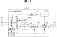
- FIG. 12 illustrates a configuration example of the ultrasonic imaging apparatus according to the third embodiment.
- FIG. 13 is a block diagram illustrating a hardware configuration example of the image processing apparatus 108 and the user interface 121 according to the third embodiment. 12 and 13, a position detection unit 6 and a position sensor 8 are further added to the configuration of the first embodiment.
- the position detection unit 6 detects the position of the ultrasonic probe 7 from the output of the position sensor 8.
- a magnetic sensor unit can be used as the position detection unit 6.
- the position detection unit 6 can detect the coordinates from the position serving as the reference point, that is, the position information of the ultrasonic probe, by forming a magnetic field space and the magnetic sensor as the position sensor 8 detecting the magnetic field. .
- FIG. 3 is a functional block diagram illustrating a functional example of the image processing apparatus 108 according to the third embodiment. Further, the operation processing of the image processing apparatus 108 in the third embodiment shown in FIG. 3 is as shown in the flowchart of FIG.
- the image generation unit 107 generates an ultrasonic image from the reception signal of the ultrasonic probe 7, and generates ultrasonic 3D from the ultrasonic image and the position information of the ultrasonic probe obtained from the position sensor 8. Generate an image.
- the ultrasonic 2D-3D image alignment unit 25 detects the position information of the ultrasonic probe added to the ultrasonic 3D image and the ultrasonic 2D imaged in real time during the operation. An alignment transformation matrix for performing alignment is calculated using the position information of the ultrasound probe added to the image.
- Other processes in the third embodiment are the same as those in the first embodiment.
- the position sensor is attached to the ultrasonic probe, the ultrasonic image is generated from the reception signal of the ultrasonic probe, and the ultrasonic probe obtained from the ultrasonic image and the position sensor is used.
- An ultrasonic 3D image is generated from the position information of the tentacles, and position estimation and name identification are performed on a predetermined anatomical feature portion from the ultrasonic 3D image.
- the position information of the identified characteristic part is registered by aligning the ultrasonic 2D image and the ultrasonic 3D image using the position information of the ultrasonic probe.
- an ultrasonic imaging apparatus capable of displaying the name and information on the distance relationship with the ultrasonic 2D image on the ultrasonic 2D image can be configured.
- the position of a predetermined anatomical characteristic part is estimated and the name is identified from an ultrasound 3D image, and an ultrasound scan that is an ultrasound 3D image and an ultrasound 2D image captured in real time. Alignment with the two-dimensional image of the surface, projecting the position of the feature part on the ultrasound 2D image, calculating the distance relationship between the feature part and the ultrasound 2D image, and positioning the feature part on the ultrasound 2D image.
- the ultrasonic imaging apparatus which displays the name and the information on the distance relationship with the ultrasonic 2D image can be provided.
- the present invention is not limited to the ultrasonic imaging apparatus, but can be realized as an image processing apparatus connected to the ultrasonic imaging apparatus via a network and an image processing method thereof.
- a part of the configuration of one embodiment can be replaced with the configuration of another embodiment, and the configuration of another embodiment can be added to the configuration of one embodiment. Further, it is possible to add, delete, and replace other configurations for a part of the configuration of each embodiment.
Abstract
The present invention displays, automatically and in real time, information of an anatomical feature part of a subject, in an intraoperative ultrasound image, and accurately guides an operation. An ultrasound imaging device comprises: an image generation unit that transmits ultrasonic waves to a subject, generates an ultrasonic 2D image from reception signals of an ultrasonic probe which receives ultrasonic waves from a subject, and generates an ultrasonic 3D image by sending and receiving ultrasonic waves multiple times; and an image processing device that processes the ultrasonic 2D image and the ultrasonic 3D image. The image processing device includes: an ultrasonic 3D image feature part position estimation and identification unit 22 that estimates and identifies a feature part of a subject from an ultrasonic 3D image acquired by an ultrasonic 3D image acquisition unit 21; an ultrasonic 2D-3D image position aligning unit 25 that aligns the positions of the ultrasonic 2D image and the ultrasonic 3D image; and an image display unit 26 that uses obtained feature part position information and the position alignment results to display, on a real-time ultrasonic 2D image, information on the feature part position, name and distance relationship with the ultrasonic 2D image.
Description
本発明は、超音波撮像装置に係り、特に、撮像した超音波画像と、被検体内所定の特徴部位を同時に表示する撮像技術に関する。
The present invention relates to an ultrasonic imaging apparatus, and more particularly to an imaging technique for simultaneously displaying an imaged ultrasonic image and a predetermined characteristic part in a subject.
超音波撮像装置は、超音波を被検体に照射し、その反射信号により被検体内部の構造を画像化するため、無侵襲かつリアルタイムに患者を観察することが可能である。また、超音波探触子に位置センサを貼り付けてスキャン面の位置関係を算出し、医用画像診断装置から撮像した3次元診断用ボリューム(3D画像)データから、超音波スキャン面の画像に対応する2次元断面画像を構築し、表示する画像診断システムも普及し始めている。その診断用3D画像データは、超音波のほか、X線CT(Computed Tomography)装置あるいはMRI(Magnetic Resonance Imaging)装置などの他の医用画像撮像装置から撮像された画像データが一般的である。
Since the ultrasonic imaging apparatus irradiates the subject with ultrasonic waves and images the structure inside the subject using the reflected signal, the patient can be observed non-invasively and in real time. In addition, the positional relationship of the scan plane is calculated by attaching a position sensor to the ultrasonic probe, and it corresponds to the image of the ultrasonic scan plane from the three-dimensional diagnostic volume (3D image) data captured from the medical image diagnostic apparatus. An image diagnostic system that constructs and displays a two-dimensional cross-sectional image is also becoming popular. The diagnostic 3D image data is generally image data taken from another medical image pickup device such as an X-ray CT (Computed Tomography) device or an MRI (Magnetic Resonance Imaging) device in addition to ultrasound.
特許文献1には、医用画像診断装置から撮像した診断用3次元(3D)画像データから、超音波スキャン面の画像である超音波2次元(2D)画像に対応する2次元断面画像を構築する際に、診断目的および超音波プローブの種類に応じて2次元断面画像の断面方向を設定する。得られた断面方向と超音波探触子に貼り付けられた位置センサの位置情報に基づいて、超音波スキャン面の画像と診断用3D画像との位置合わせを行い、診断用3D画像から2次元断面画像を構築し表示する。また、非特許文献1は、超音波3D画像のスティッチング法などを開示している。
In Patent Document 1, a two-dimensional cross-sectional image corresponding to an ultrasonic two-dimensional (2D) image that is an image of an ultrasonic scan plane is constructed from diagnostic three-dimensional (3D) image data captured from a medical image diagnostic apparatus. At this time, the cross-sectional direction of the two-dimensional cross-sectional image is set according to the purpose of diagnosis and the type of the ultrasonic probe. Based on the obtained cross-sectional direction and the position information of the position sensor attached to the ultrasonic probe, the ultrasonic scan plane image and the diagnostic 3D image are aligned, and the diagnostic 3D image is two-dimensionally converted. Build and display cross-sectional images. Non-Patent Document 1 discloses an ultrasonic 3D image stitching method and the like.
近年では、被検体の手術中に腫瘍等の手術すべき領域を、無侵襲かつリアルタイムで撮像できる術中超音波画像で確認することが望まれている。さらに、手術を正確にガイドするためには、術中超音波画像に、被検体内腫瘍や解剖学的な特徴部位の位置、名称、および距離関係などの情報をリアルタイムに表示することが望まれている。また、手術中の医師等のユーザの手が、術中超音波画像と被検体との位置合わせのために、手動入力装置のスイッチやマウス等に触ることはできるだけ避けたい。また、開腹状態の被検体の負担を軽減するために、できるだけ短時間に位置合わせを行うことが望ましい。
In recent years, it has been desired to confirm an area to be operated such as a tumor during an operation on a subject with an intraoperative ultrasound image that can be imaged non-invasively and in real time. Furthermore, in order to accurately guide the operation, it is desired to display information such as the position, name, and distance relationship of the tumor in the subject and the anatomical features in real time on the intraoperative ultrasound image. Yes. In addition, it is desirable to avoid as much as possible that the hand of a user such as a doctor during surgery touches a switch or a mouse of a manual input device in order to align the intraoperative ultrasound image and the subject. In addition, it is desirable to perform alignment in as short a time as possible in order to reduce the burden on the subject in the open state.
しかしながら、特許文献1の技術では、ユーザにより、超音波スキャン面の画像と診断用3D画像から構築される2次元断面画像の両方で観察可能な目印上に点を設定し位置を一致させる目印合わせにより位置合わせを行う必要がある。このような繁雑なユーザ操作および開腹状態の被検体の負担が大きな課題である。また、特許文献1の技術では、解剖学的な特徴部位の位置や名称などの情報をリアルタイムに表示できないという課題がある。
However, in the technique of Patent Document 1, a user sets a point on a mark that can be observed on both the ultrasonic scan plane image and the two-dimensional cross-sectional image constructed from the diagnostic 3D image, and matches the positions. Need to be aligned. Such a complicated user operation and the burden on the subject in an open state are major issues. Moreover, in the technique of Patent Document 1, there is a problem that information such as the position and name of an anatomical feature portion cannot be displayed in real time.
本発明の目的は、術中超音波画像に特徴部位の情報を自動的かつリアルタイムに表示し、手術を正確にガイドすることが可能な超音波撮像装置、画像処理装置、及びその方法を提供することにある。
An object of the present invention is to provide an ultrasonic imaging apparatus, an image processing apparatus, and a method thereof that are capable of automatically and in real time displaying information on characteristic parts in an intraoperative ultrasonic image and accurately guiding a surgery. It is in.
上記の目的を達成するため、本発明においては、超音波撮像装置であって、被検体に超音波を送信し、被検体からの超音波を受信する超音波探触子と、超音波探触子の受信信号から超音波2D画像を生成し、複数回の超音波の送受信により超音波3D画像を生成する画像生成部と、超音波2D画像と超音波3D画像を受け取って処理する画像処理装置とを備え、画像処理装置は、超音波3D画像から被検体の特徴部位を推定および識別し、超音波2D画像と超音波3D画像との位置合わせを行い、超音波2D画像上に、特徴部位の情報を表示する超音波撮像装置を提供する。
In order to achieve the above object, according to the present invention, there is provided an ultrasonic imaging apparatus that transmits an ultrasonic wave to a subject and receives an ultrasonic wave from the subject, and an ultrasonic probe. An image generation unit that generates an ultrasonic 2D image from a received signal of a child and generates an ultrasonic 3D image by transmitting and receiving ultrasonic waves a plurality of times, and an image processing device that receives and processes the ultrasonic 2D image and the ultrasonic 3D image The image processing apparatus estimates and identifies the characteristic part of the subject from the ultrasonic 3D image, aligns the ultrasonic 2D image and the ultrasonic 3D image, and places the characteristic part on the ultrasonic 2D image. An ultrasonic imaging apparatus for displaying the information is provided.
また、上記の目的を達成するため、本発明においては、画像処理装置であって、被検体についての超音波3D画像から被検体の特徴部位を推定および識別する特徴部位位置推定・識別部と、被検体についての超音波2D画像と、超音波3D画像との位置合わせを行い、超音波2D画像に対応する超音波3D画像の2D断面画像の位置を算出する画像位置合わせ部とを備える画像処理装置を提供する。
In order to achieve the above object, according to the present invention, an image processing apparatus includes a feature part position estimation / identification unit that estimates and identifies a feature part of a subject from an ultrasonic 3D image of the subject, Image processing including an image alignment unit that performs alignment between the ultrasonic 2D image and the ultrasonic 3D image of the subject and calculates the position of the 2D cross-sectional image of the ultrasonic 3D image corresponding to the ultrasonic 2D image Providing the device.
さらに、上記の目的を達成するため、本発明においては、画像処理装置における画像処理方法であって、画像処理装置は、被検体についての超音波3D画像から被検体の特徴部位を推定および識別し、被検体についての超音波2D画像と、超音波3D画像との位置合わせを行い、超音波2D画像に対応する前記超音波3D画像の2D断面画像の位置を算出する画像処理方法を提供する。
Furthermore, in order to achieve the above object, according to the present invention, there is provided an image processing method in an image processing apparatus, wherein the image processing apparatus estimates and identifies a characteristic part of a subject from an ultrasonic 3D image of the subject. Provided is an image processing method for aligning an ultrasonic 2D image and an ultrasonic 3D image of a subject and calculating a position of a 2D cross-sectional image of the ultrasonic 3D image corresponding to the ultrasonic 2D image.
本発明によれば、超音波3D画像から被検体の特徴部位を推定および識別し、超音波2D画像と超音波3D画像との位置合わせを行い、特徴部位の情報を超音波2D画像に表示することにより、手術を正確にガイドすることが可能となる。
According to the present invention, the characteristic part of the subject is estimated and identified from the ultrasonic 3D image, the ultrasonic 2D image and the ultrasonic 3D image are aligned, and the characteristic part information is displayed on the ultrasonic 2D image. Therefore, it is possible to accurately guide the operation.
以下、本発明の実施の形態を図面に基づいて詳細に説明する。なお、実施の形態を説明するための全図において、同一部分には原則として同一の符号を付し、その繰り返しの説明は省略する。なお、本明細書において、特徴部位の情報とは、特徴部位の位置、名称、更には距離関係の情報を意味し、距離関係とは、特徴部位から超音波2D画像までの投影距離を意味する。
Hereinafter, embodiments of the present invention will be described in detail with reference to the drawings. Note that components having the same function are denoted by the same reference symbols throughout the drawings for describing the embodiment, and the repetitive description thereof will be omitted. In this specification, the feature part information means the position and name of the feature part, and also the distance relation information, and the distance relation means the projection distance from the feature part to the ultrasonic 2D image. .
実施例1は、超音波撮像装置であって、被検体に超音波を送信し、被検体からの超音波を受信する超音波探触子と、超音波探触子の受信信号から超音波2D画像を生成し、複数回の超音波の送受信により超音波3D画像を生成する画像生成部と、超音波2D画像と超音波3D画像を受け取って処理する画像処理装置とを備え、画像処理装置は、超音波3D画像から被検体の特徴部位を推定および識別し、超音波2D画像と超音波3D画像との位置合わせを行い、超音波2D画像上に、特徴部位の情報を表示する超音波撮像装置の実施例である。また、画像処理装置であって、被検体についての超音波3D画像から被検体の特徴部位を推定および識別する特徴部位位置推定・識別部と、被検体についての超音波2D画像と、超音波3D画像との位置合わせを行い、超音波2D画像に対応する超音波3D画像の2D断面画像の位置を算出する画像位置合わせ部とを備える画像処理装置、およびその方法の実施例である。
The first embodiment is an ultrasonic imaging apparatus that transmits an ultrasonic wave to a subject and receives an ultrasonic wave from the subject, and an ultrasonic wave 2D from a reception signal of the ultrasonic probe. The image processing apparatus includes an image generation unit that generates an image and generates an ultrasonic 3D image by transmitting and receiving ultrasonic waves a plurality of times, and an image processing apparatus that receives and processes the ultrasonic 2D image and the ultrasonic 3D image. The ultrasonic imaging that estimates and identifies the characteristic part of the subject from the ultrasonic 3D image, aligns the ultrasonic 2D image and the ultrasonic 3D image, and displays the characteristic part information on the ultrasonic 2D image It is the Example of an apparatus. In addition, the image processing apparatus is a feature part position estimation / identification unit that estimates and identifies a feature part of a subject from an ultrasound 3D image of the subject, an ultrasound 2D image of the subject, and an ultrasound 3D. It is an Example of an image processing apparatus provided with the image position alignment part which performs position alignment with an image and calculates the position of 2D cross-sectional image of the ultrasonic 3D image corresponding to an ultrasonic 2D image, and its method.
本実施例の超音波撮像装置においては、被検体を撮像した超音波3D画像から、所定の解剖学的な特徴部位に対し、位置推定と名称識別を行う。また、手術中にリアルタイムに撮像した超音波2D画像、すなわち超音波スキャン面の2D画像と超音波3D画像との位置合わせを行い、位置合わせ用の幾何変換行列を算出し、推定された特徴部位の位置と、撮像した超音波2D画像との距離関係を算出する。得られた特徴部位の名称・位置と、超音波2D画像との距離関係を、特徴部位の情報として超音波2D画像上に表示することにより、リアルタイムに手術をガイドすることを可能とする。
In the ultrasonic imaging apparatus according to the present embodiment, position estimation and name identification are performed on a predetermined anatomical feature portion from an ultrasonic 3D image obtained by imaging a subject. In addition, an ultrasonic 2D image captured in real time during surgery, that is, a 2D image of an ultrasonic scan surface and an ultrasonic 3D image are aligned, a geometric transformation matrix for alignment is calculated, and an estimated feature part And the distance relationship between the position of the captured ultrasonic 2D image. By displaying the distance / relationship between the name / position of the obtained characteristic part and the ultrasonic 2D image on the ultrasonic 2D image as characteristic part information, it is possible to guide the operation in real time.
ここで、本実施例における特徴部位の情報の一つである距離関係は、被検体内の特徴部位から超音波2D画像までの投影距離を意味する。好適には、超音波3D画像から推定された被検体の特徴部位の3次元的な位置、すなわち、3D空間上の点の座標から、超音波2D画像に対応する超音波3D画像の2D断面画像の位置、すなわち3次元空間上の面の位置までの投影距離を算出し、この算出した投影距離を特徴部位の超音波2D画像との距離関係とする。
Here, the distance relationship which is one of the information on the characteristic part in the present embodiment means the projection distance from the characteristic part in the subject to the ultrasonic 2D image. Preferably, the 2D cross-sectional image of the ultrasonic 3D image corresponding to the ultrasonic 2D image from the three-dimensional position of the characteristic part of the subject estimated from the ultrasonic 3D image, that is, the coordinates of the point in the 3D space. , That is, the projection distance to the position of the surface in the three-dimensional space, and the calculated projection distance is set as a distance relationship with the ultrasonic 2D image of the characteristic part.
<構成及び動作>
以下、実施例1の超音波撮像装置の具体的な一構成例について詳述する。図1に示すように、本実施例の超音波撮像装置は、超音波探触子7と、画像生成部107と、画像処理装置108とを備え、さらに、送信部102、送受切替部101、受信部105、ユーザインタフェース(UI)121、および、制御部106とから構成される。この超音波撮像装置100で得られる画像は、ディスプレイ16に表示される。なお、ディスプレイ16は、ユーザインタフェース(UI)121に含まれる構成であっても良い。図1に示す超音波撮像装置の構成例は、他の実施例においても共通に利用される。 <Configuration and operation>
Hereinafter, a specific configuration example of the ultrasonic imaging apparatus according to the first embodiment will be described in detail. As shown in FIG. 1, the ultrasonic imaging apparatus of the present embodiment includes anultrasonic probe 7, an image generation unit 107, and an image processing device 108, and further includes a transmission unit 102, a transmission / reception switching unit 101, The receiving unit 105, a user interface (UI) 121, and a control unit 106 are configured. An image obtained by the ultrasonic imaging apparatus 100 is displayed on the display 16. The display 16 may be included in the user interface (UI) 121. The configuration example of the ultrasonic imaging apparatus shown in FIG. 1 is commonly used in other embodiments.
以下、実施例1の超音波撮像装置の具体的な一構成例について詳述する。図1に示すように、本実施例の超音波撮像装置は、超音波探触子7と、画像生成部107と、画像処理装置108とを備え、さらに、送信部102、送受切替部101、受信部105、ユーザインタフェース(UI)121、および、制御部106とから構成される。この超音波撮像装置100で得られる画像は、ディスプレイ16に表示される。なお、ディスプレイ16は、ユーザインタフェース(UI)121に含まれる構成であっても良い。図1に示す超音波撮像装置の構成例は、他の実施例においても共通に利用される。 <Configuration and operation>
Hereinafter, a specific configuration example of the ultrasonic imaging apparatus according to the first embodiment will be described in detail. As shown in FIG. 1, the ultrasonic imaging apparatus of the present embodiment includes an
送信部102は、制御部106の制御下で、送信信号を生成し、超音波プローブと呼ばれる超音波探触子7を構成する複数の超音波素子各々に受け渡す。これにより、超音波探触子7の複数の超音波素子は、それぞれ超音波を被検体120に向かって送信する。被検体120で反射等された超音波は、再び超音波探触子7の複数の超音波素子に到達して受信され、電気信号に変換される。超音波素子が受信した信号は、受信部105によって、受信焦点の位置に応じた所定の遅延量で遅延され、整相加算される。これを複数の受信焦点ごとについて繰り返す。整相加算信号は、受信部105から画像生成部107に受け渡される。送受切替部101は、送信部102または受信部105を選択的に超音波探触子7に接続する。
The transmission unit 102 generates a transmission signal under the control of the control unit 106 and passes it to each of a plurality of ultrasonic elements constituting the ultrasonic probe 7 called an ultrasonic probe. Thereby, each of the plurality of ultrasonic elements of the ultrasonic probe 7 transmits an ultrasonic wave toward the subject 120. The ultrasonic waves reflected by the subject 120 reach the plural ultrasonic elements of the ultrasonic probe 7 again and are received and converted into electric signals. The signal received by the ultrasonic element is delayed by a predetermined delay amount corresponding to the position of the reception focal point and phased and added by the receiving unit 105. This is repeated for each of a plurality of reception focal points. The phasing addition signal is transferred from the reception unit 105 to the image generation unit 107. The transmission / reception switching unit 101 selectively connects the transmission unit 102 or the reception unit 105 to the ultrasound probe 7.
画像生成部107は、受信部105から受け取った整相加算信号を受信焦点に対応する位置に並べる等の処理を行い、超音波2D画像を生成する。ユーザが超音波探触子7を煽りながら、画像生成部107が複数の超音波2D画像を生成して、超音波3D画像を合成ことができる。
The image generation unit 107 performs processing such as arranging the phasing addition signal received from the reception unit 105 at a position corresponding to the reception focus, and generates an ultrasonic 2D image. While the user rolls the ultrasonic probe 7, the image generation unit 107 can generate a plurality of ultrasonic 2D images and synthesize the ultrasonic 3D images.
画像処理装置108は、画像生成部107から超音波3D画像を受け取って、所定の解剖学的な特徴部位の名称識別と位置推定を行う。また、画像処理装置108は、リアルタイムに生成した超音波2D画像を受け取って、超音波2D画像と超音波3D画像との位置合わせを行い、得られた特徴部位の名称・位置と、超音波2D画像との距離関係を、リアルタイムに生成した超音波2D画像に表示する。
The image processing apparatus 108 receives the ultrasonic 3D image from the image generation unit 107, and performs name identification and position estimation of a predetermined anatomical feature part. Further, the image processing apparatus 108 receives the ultrasonic 2D image generated in real time, aligns the ultrasonic 2D image and the ultrasonic 3D image, and obtains the name and position of the obtained characteristic part and the ultrasonic 2D. The distance relationship with the image is displayed on the ultrasonic 2D image generated in real time.
以下、画像処理装置108とユーザインタフェース(UI)121の具体的な構成と動作について詳しく説明する。
図2は、画像処理装置108とユーザインタフェース121のハードウェア構成例を示すブロック図である。図2に示すハードウェア構成例は、図1の超音波撮像装置の構成同様、他の実施例においても、共通に用いられる。 Hereinafter, specific configurations and operations of theimage processing apparatus 108 and the user interface (UI) 121 will be described in detail.
FIG. 2 is a block diagram illustrating a hardware configuration example of theimage processing apparatus 108 and the user interface 121. The hardware configuration example shown in FIG. 2 is commonly used in other embodiments as well as the configuration of the ultrasonic imaging apparatus in FIG.
図2は、画像処理装置108とユーザインタフェース121のハードウェア構成例を示すブロック図である。図2に示すハードウェア構成例は、図1の超音波撮像装置の構成同様、他の実施例においても、共通に用いられる。 Hereinafter, specific configurations and operations of the
FIG. 2 is a block diagram illustrating a hardware configuration example of the
画像処理装置108は、CPU(プロセッサ)1、ROM(不揮発性メモリ:読出専用の記憶媒体)2、RAM(揮発性メモリ:データの読み書きが可能な記憶媒体)3、記憶装置4、及び表示制御部15を備えている。ユーザインタフェース121は、媒体入力部11、入力制御部13および入力装置14、及びディスプレイ16を備えている。画像生成部107、画像処理装置108、ユーザインタフェース121は、バス5によって相互に接続されている。
The image processing apparatus 108 includes a CPU (processor) 1, a ROM (nonvolatile memory: a read-only storage medium) 2, a RAM (volatile memory: a storage medium capable of reading and writing data) 3, a storage device 4, and display control. Part 15 is provided. The user interface 121 includes a medium input unit 11, an input control unit 13 and an input device 14, and a display 16. The image generation unit 107, the image processing apparatus 108, and the user interface 121 are connected to each other via the bus 5.
画像処理装置108のROM2およびRAM3の少なくとも一方には、画像処理装置108の動作を実現するために必要とされるCPU1の演算処理のためのプログラムとデータが予め格納されている。CPU1が、このROM2およびRAM3の少なくとも一方に予め格納されたプログラムを実行することによって、画像処理装置108の各種処理が実現される。なお、CPU1が実行するプログラムは、例えば、光ディスクなどの記憶媒体12に格納しておき、媒体入力部11(例えば、光ディスクドライブ)がそのプログラムを読み込んでRAM3に格納する様にしてもよい。また、記憶装置4に当該プログラムを格納しておき、記憶装置4からそのプログラムをRAM3にロードしてもよい。また、ROM2にあらかじめ当該プログラムを記憶させておいてもよい。
At least one of the ROM 2 and the RAM 3 of the image processing apparatus 108 stores in advance a program and data for the arithmetic processing of the CPU 1 necessary for realizing the operation of the image processing apparatus 108. Various processes of the image processing apparatus 108 are realized by the CPU 1 executing a program stored in advance in at least one of the ROM 2 and the RAM 3. The program executed by the CPU 1 may be stored in a storage medium 12 such as an optical disk, for example, and the medium input unit 11 (for example, an optical disk drive) may read the program and store it in the RAM 3. Alternatively, the program may be stored in the storage device 4 and the program may be loaded from the storage device 4 into the RAM 3. Further, the program may be stored in the ROM 2 in advance.
記憶装置4は、例えば、フラッシュメモリなどの不揮発性半導体記憶媒体を備えてもよい。また、ネットワークなどを介して接続された外部記憶装置を利用してもよい。
The storage device 4 may include a nonvolatile semiconductor storage medium such as a flash memory, for example. An external storage device connected via a network or the like may be used.
入力装置14は、ユーザの操作を受け付ける装置であり、例えば、キーボード、トラックボール、操作パネル、フットスイッチなどを含む。入力制御部13は、ユーザによって入力された操作入力を受け付ける。入力制御部13が受けた操作入力は、CPU1によって処理される。表示制御部15は、例えば、CPU1の処理で得られた画像データをディスプレイ16に表示させる制御を行う。ディスプレイ16は、表示制御部15の制御下で画像を表示する。
The input device 14 is a device that receives user operations, and includes, for example, a keyboard, a trackball, an operation panel, a foot switch, and the like. The input control unit 13 receives an operation input input by a user. The operation input received by the input control unit 13 is processed by the CPU 1. For example, the display control unit 15 performs control to display the image data obtained by the processing of the CPU 1 on the display 16. The display 16 displays an image under the control of the display control unit 15.
図3は、本実施例の画像処理装置108の一機能を示す機能ブロック図である。図3に示すように、画像処理装置108は、超音波3D画像取得部21と、超音波3D画像の特徴部位位置推定・識別部22と、超音波2D画像取得部24とを含む。更に、画像処理装置108は、特徴部位の名称・位置の情報を示す超音波特徴部位情報23と、超音波2D-3D画像位置合わせ部25と、画像表示部26とを含む。
FIG. 3 is a functional block diagram showing one function of the image processing apparatus 108 of the present embodiment. As illustrated in FIG. 3, the image processing apparatus 108 includes an ultrasonic 3D image acquisition unit 21, an ultrasonic 3D image feature site position estimation / identification unit 22, and an ultrasonic 2D image acquisition unit 24. Further, the image processing apparatus 108 includes ultrasonic feature part information 23 indicating information on the name and position of the feature part, an ultrasonic 2D-3D image registration unit 25, and an image display unit 26.
図4に示すフローチャートを用いて、図3に示した画像処理装置108の動作処理を説明する。まず、ステップS201において、超音波探触子7を当てて、煽りながらスキャンを行うように促す表示をディスプレイ16に表示する。ユーザが表示に従い超音波探触子7をその臓器の区域でスキャンすると、送信部102、受信部105および画像生成部107により、連続的に超音波2D画像が生成される。画像生成部107により、連続的に生成された超音波2D画像から超音波3D画像が合成される。超音波3D画像取得部21は、合成された超音波3D画像を受け付ける。
The operation processing of the image processing apparatus 108 shown in FIG. 3 will be described using the flowchart shown in FIG. First, in step S201, the ultrasonic probe 7 is applied and a display prompting the user to perform scanning while turning is displayed on the display 16. When the user scans the ultrasound probe 7 in the area of the organ according to the display, the transmission unit 102, the reception unit 105, and the image generation unit 107 continuously generate an ultrasonic 2D image. The image generation unit 107 synthesizes an ultrasonic 3D image from continuously generated ultrasonic 2D images. The ultrasonic 3D image acquisition unit 21 receives the synthesized ultrasonic 3D image.
ステップS202において、超音波3D画像の特徴部位位置推定・識別部22は、公知の機械学習の手法を用いて、超音波3D画像から、所定の解剖学的な特徴部位の位置を推定し、推定結果に従い、各特徴部位の名称を識別する。ここで特徴部位とは、例えば肝臓の門脈臍部、下大静脈の流入部、胆嚢、そして肝臓門脈や静脈の各分岐点など、医学的に定義されている臓器や臓器内の部位である。
In step S202, the characteristic part position estimation / identification unit 22 of the ultrasonic 3D image estimates the position of a predetermined anatomical characteristic part from the ultrasonic 3D image using a known machine learning technique, and estimates According to the result, the name of each characteristic part is identified. Here, the characteristic site is a medically defined organ or site within the organ such as the portal vein umbilicus of the liver, the inflow of the inferior vena cava, the gallbladder, and the bifurcation points of the liver portal vein or vein. is there.
図5A、図5B、図5Cは、超音波3D画像において、特徴部位としての肝臓の門脈臍部、下大静脈の流入部、胆嚢の3次元的な位置や画像の特徴を示す説明図である。図5A、図5B、図5Cに示した立方体50が上記の解剖学的な特徴部位それぞれの位置の周囲局所領域を示している。超音波3D画像の特徴部位位置推定・識別部22における特徴部位の位置推定と名称識別の詳細は後で述べる。
FIG. 5A, FIG. 5B, and FIG. 5C are explanatory diagrams showing the three-dimensional position of the portal vein umbilical portion of the liver, the inflow portion of the inferior vena cava, and the features of the gallbladder as features in the ultrasound 3D image. is there. The cube 50 shown in FIG. 5A, FIG. 5B, and FIG. 5C shows the surrounding local area | region of the position of each said anatomical feature part. Details of the position estimation and name identification of the characteristic part in the characteristic part position estimation / identification unit 22 of the ultrasonic 3D image will be described later.
図6に、超音波特徴部位情報23である、超音波3D画像から推定・識別された特徴部位の名称、および3次元位置情報の一例を示す。これらの超音波特徴部位情報23は、RAM3や記憶装置4などにテーブルとして記憶することができる。
FIG. 6 shows an example of the characteristic part name estimated and identified from the ultrasonic 3D image and the three-dimensional position information as the ultrasonic characteristic part information 23. These ultrasonic characteristic part information 23 can be stored as a table in the RAM 3 or the storage device 4.
ステップS203において、超音波2D画像取得部24は、画像生成部107からリアルタイムに取得した2D超音波画像を受け付ける。
In step S203, the ultrasonic 2D image acquisition unit 24 receives the 2D ultrasonic image acquired in real time from the image generation unit 107.
ステップS204において、超音波2D-3D画像位置合わせ部25は、超音波3D画像取得部21と超音波2D画像取得部24から、超音波3D画像と超音波2D画像をそれぞれ受け付けて両者の位置合わせを行うための位置合わせ変換行列を算出する。位置合わせ変換行列算出の詳細は後で述べる。
In step S204, the ultrasonic 2D-3D image registration unit 25 receives the ultrasonic 3D image and the ultrasonic 2D image from the ultrasonic 3D image acquisition unit 21 and the ultrasonic 2D image acquisition unit 24, respectively, and aligns the two. A registration transformation matrix for performing the above is calculated. Details of the alignment transformation matrix calculation will be described later.
ステップS205において、画像表示部26は超音波3D画像と、超音波2D画像と、超音波特徴部位情報23と、位置合わせ変換行列と、更には2D断面画像の位置を受け取る。画像表示部26は、これらのデータを用いて、被検体の特徴部位の3D空間上の点の座標から、超音波2D画像に対応する超音波3D画像の2D断面画像の位置までの投影距離を算出し、この算出した投影距離を特徴部位の超音波2D画像との距離関係とする。そして、画像表示部26は、超音波2D画像を、図11の(a)に一例を示すようにディスプレイ16の画面に表示する。そして、識別された特徴部位の位置、名称17A、18Aと、特徴部位と超音波2D画像との距離関係を画面上に表示する。その際、画像表示部26は、位置合わせ変換行列を用いて、超音波3D画像の3次元座標系における特徴部位の位置から、現在表示されている超音波2D画像へ投影し、投影された場所に特徴部位の場所と×印で示すマーカ17B、18Bを表示する。すなわち、画像表示部26は、超音波3D画像から推定した特徴部位の名称と、特徴部位とリアルタイムに取得した超音波2D画像との位置関係を、ディスプレイ16上の超音波2D画像にリアルタイムに表示することができるため、ユーザに対する正確な手術ナビゲーションを実現することができる。
In step S205, the image display unit 26 receives the ultrasonic 3D image, the ultrasonic 2D image, the ultrasonic characteristic part information 23, the alignment conversion matrix, and further the position of the 2D cross-sectional image. The image display unit 26 uses these data to calculate the projection distance from the coordinates of the point on the 3D space of the characteristic part of the subject to the position of the 2D cross-sectional image of the ultrasonic 3D image corresponding to the ultrasonic 2D image. The calculated projection distance is set as a distance relationship with the ultrasonic 2D image of the characteristic part. Then, the image display unit 26 displays the ultrasonic 2D image on the screen of the display 16 as shown in an example in FIG. Then, the position of the identified feature part, names 17A and 18A, and the distance relationship between the feature part and the ultrasonic 2D image are displayed on the screen. At that time, the image display unit 26 uses the alignment conversion matrix to project from the position of the characteristic part in the three-dimensional coordinate system of the ultrasonic 3D image to the currently displayed ultrasonic 2D image, and the projected location The markers 17B and 18B indicated by the location of the characteristic part and the X mark are displayed. That is, the image display unit 26 displays in real time on the ultrasonic 2D image on the display 16 the name of the characteristic part estimated from the ultrasonic 3D image and the positional relationship between the characteristic part and the ultrasonic 2D image acquired in real time. Therefore, accurate surgical navigation for the user can be realized.
上述した通り、画像表示部26は、超音波3D画像から推定された被検体の特徴部位の3D空間上の点の座標から、超音波2D画像に対応する超音波3D画像の2D断面画像の位置までの投影距離を算出し、特徴部位とリアルタイムに取得した超音波2D画像との距離関係とする。そして、マーカ17B、18Bのサイズを、算出した特徴部位と超音波2D画像との距離関係である投影距離に比例して表示する。すなわち、画像表示部26では、超音波2D画像上に特徴部位を示すマーカを表示する際に、マーカ17B、18Bのサイズを算出した投影距離と比例するように表示することにより、両者の位置関係が一目で把握できるのでユーザの使い勝手がより向上する。
As described above, the image display unit 26 determines the position of the 2D cross-sectional image of the ultrasonic 3D image corresponding to the ultrasonic 2D image from the coordinates of the point on the 3D space of the characteristic part of the subject estimated from the ultrasonic 3D image. Is calculated as the distance relationship between the characteristic part and the ultrasonic 2D image acquired in real time. Then, the sizes of the markers 17B and 18B are displayed in proportion to the projection distance that is the distance relationship between the calculated feature portion and the ultrasonic 2D image. That is, in the image display unit 26, when displaying the marker indicating the characteristic part on the ultrasonic 2D image, the size of the markers 17B and 18B is displayed in proportion to the calculated projection distance, whereby the positional relationship between the two is displayed. Can be grasped at a glance, so that the usability of the user is further improved.
なお、画像表示部26は、チェックボックス28のユーザ選択により、特徴部位の名称17A、18Aと、マーカ17B、18Bの表示をオンとオフにすることができ、ユーザが必要とする場合にのみ、特徴部位の名称17A、18Aと、マーカ17B、18Bを表示することができる。なお、図11の(a)のタッチパネル操作ボタン19、及び図11の(b)については、実施例2において説明する。
The image display unit 26 can turn on and off the display of the feature part names 17A and 18A and the markers 17B and 18B by user selection of the check box 28, and only when the user needs it. Characteristic part names 17A and 18A and markers 17B and 18B can be displayed. Note that the touch panel operation button 19 in FIG. 11A and FIG. 11B are described in the second embodiment.
また、ステップS205の表示の際に、画像表示部26は、リアルタイムの超音波2D画像と、超音波3D画像の超音波2D画像に対応する位置の2D断面画像の内の一方の色を変えて、これら二つを透過的に重畳した画像を生成して、ディスプレイ16に表示することができる。さらに、画像表示部26は、特徴部位の名称17A、18Aとマーカ17B、18Bを、重畳して生成した2D画像に表示する。この場合においても、画像表示部26はマーカ17B、18Bのサイズを、算出した特徴部位から超音波2D画像への投影距離に比例して表示することが可能である。
Further, at the time of the display in step S205, the image display unit 26 changes one color of the real-time ultrasonic 2D image and the 2D cross-sectional image at a position corresponding to the ultrasonic 2D image of the ultrasonic 3D image. An image in which these two are superimposed transparently can be generated and displayed on the display 16. Furthermore, the image display unit 26 displays the feature part names 17A and 18A and the markers 17B and 18B on the 2D image generated by superimposing them. Even in this case, the image display unit 26 can display the size of the markers 17B and 18B in proportion to the calculated projection distance from the characteristic part to the ultrasonic 2D image.
続いて図7に示すフローチャートを用いて、本実施例の超音波3D画像の特徴部位位置推定・識別部22の処理を詳述する。先に説明した通り、画像処理装置108は、CPU1のプログラム実行によって実現されるため、図7の各処理もCPU1のプログラム処理によって実現される。
Subsequently, the processing of the characteristic part position estimation / identification unit 22 of the ultrasonic 3D image of the present embodiment will be described in detail using the flowchart shown in FIG. As described above, since the image processing apparatus 108 is realized by the program execution of the CPU 1, each process of FIG. 7 is also realized by the program process of the CPU 1.
まず、ステップS401において、超音波3D画像の特徴部位位置推定・識別部22は、画像生成部107から超音波3D画像を受け付ける。ステップS402においては、超音波3D画像の特徴部位位置推定・識別部22は、特徴部位候補の位置推定と名称識別を行う。処理速度を向上するため、超音波3D画像の特徴部位位置推定・識別部22は、超音波3D画像のサイズを縮小して、機械学習を用いて粗い解像度で特徴部位候補を探索する。特徴部位の位置推定と名称識別の方法としては、例えば、公知の機械学習の方法であるHough Forest法を用いることができる。
First, in step S401, the characteristic part position estimation / identification unit 22 of the ultrasonic 3D image receives the ultrasonic 3D image from the image generation unit 107. In step S402, the characteristic part position estimation / identification unit 22 of the ultrasonic 3D image performs position estimation and name identification of the characteristic part candidate. In order to improve the processing speed, the feature part position estimation / identification unit 22 of the ultrasound 3D image reduces the size of the ultrasound 3D image and searches for feature part candidates with a coarse resolution using machine learning. As a method of position estimation and name identification of a characteristic part, for example, a Hough Forest method that is a known machine learning method can be used.
つぎに、ステップS403においては、超音波3D画像の特徴部位位置推定・識別部22は、通常サイズの超音波3D画像から、探索された特徴部位候補の周囲局所領域である局所3D画像を取得する。ステップS404において、超音波3D画像の特徴部位位置推定・識別部22は、特徴部位候補の周囲局所領域において、詳細に特徴部位を探索と識別を行う。ここで、上述のHough Forest法を用いることができる。また、より高精度な位置推定・識別結果が望ましい場合、公知の深層学習(Deep Learning)方法である3D CNN(Convolutional Neural Network)法を用いることができる。
Next, in step S403, the characteristic part position estimation / identification unit 22 of the ultrasonic 3D image obtains a local 3D image that is a local region around the searched characteristic part candidate from the normal size ultrasonic 3D image. . In step S404, the feature part position estimation / identification unit 22 of the ultrasound 3D image searches and identifies the feature part in detail in the local region surrounding the feature part candidate. Here, the above Hough Forest method can be used. When a more accurate position estimation / identification result is desired, a known deep learning method 3D CNN (convolutional neural network) method can be used.
ステップS405においては、特徴部位位置推定・識別部22は、ステップS404の探索で得られた特徴部位の識別スコアが、所定の閾値以下になる場合、その特徴部位を誤識別部位として除外する。ステップS406において、超音波3D画像の特徴部位位置推定・識別部22は、識別された特徴部位の位置・名称情報を、超音波特徴部位情報23として出力する。
In step S405, the characteristic part position estimation / identification unit 22 excludes the characteristic part as an erroneous identification part when the characteristic part identification score obtained in the search in step S404 is equal to or less than a predetermined threshold. In step S <b> 406, the characteristic part position estimation / identification unit 22 of the ultrasonic 3D image outputs the position / name information of the identified characteristic part as the ultrasonic characteristic part information 23.
続いて、図8に示すフローチャートを用いて、本実施例の超音波2D-3D画像位置合わせ部25の処理を詳述する。超音波2D-3D画像位置合わせ部25の処理も、CPU1によるプログラム実行によって実現される。
Subsequently, the processing of the ultrasonic 2D-3D image alignment unit 25 of the present embodiment will be described in detail using the flowchart shown in FIG. The processing of the ultrasonic 2D-3D image alignment unit 25 is also realized by executing a program by the CPU 1.
ステップS301において、超音波2D-3D画像位置合わせ部25は、超音波3D画像取得部21から超音波3D画像、超音波2D画像取得部24から超音波2D画像を受け付けて、超音波3D画像の中から超音波2D画像の対応する3次元位置を大まかに推定する。すなわち、対応する超音波2D画像の初期位置を推定する。
In step S301, the ultrasonic 2D-3D image registration unit 25 receives the ultrasonic 3D image from the ultrasonic 3D image acquisition unit 21 and the ultrasonic 2D image from the ultrasonic 2D image acquisition unit 24, and converts the ultrasonic 3D image. The corresponding three-dimensional position of the ultrasonic 2D image is roughly estimated from the inside. That is, the initial position of the corresponding ultrasonic 2D image is estimated.
図9には、超音波2D-3D画像位置合わせ部25で用いる3次元初期位置候補の例を15パターン示している。各パターン中にそれぞれの位置91を示した。初期位置を推定する時に、機械学習を用いて超音波2D画像をこの15パターンの識別器に入力し、一番高い識別スコアを得られるパターンの位置91を超音波2D画像取得部24から得られた超音波2D画像の初期位置とする。超音波2D-3D画像位置合わせ部25は、超音波3D画像から超音波2D画像に対応する2D断面画像の3次元位置の候補を選択して初期位置として用い、超音波2D画像と前記超音波3D画像との位置合わせを行い、超音波2D画像に対応する超音波3D画像の2D断面画像を算出する。
FIG. 9 shows 15 examples of three-dimensional initial position candidates used in the ultrasonic 2D-3D image alignment unit 25. Each position 91 is shown in each pattern. When estimating the initial position, the ultrasonic 2D image is input to the 15-pattern discriminator using machine learning, and the position 91 of the pattern that can obtain the highest discrimination score is obtained from the ultrasonic 2D image acquisition unit 24. The initial position of the ultrasonic 2D image. The ultrasonic 2D-3D image registration unit 25 selects a 3D position candidate of a 2D cross-sectional image corresponding to the ultrasonic 2D image from the ultrasonic 3D image and uses it as an initial position. The ultrasonic 2D image and the ultrasonic wave Position alignment with the 3D image is performed, and a 2D cross-sectional image of the ultrasound 3D image corresponding to the ultrasound 2D image is calculated.
各パターンの識別器は学習で作成される。多数の超音波3D画像を学習データとして集めて、各々の超音波3D画像から、図9の各位置91における2D断面画像を抽出し、その位置に対応するパターンの学習データとして作成する。また、学習データの数量と多様性を増やすために、図9の各位置91から、ランダムかつ小範囲の平行移動と回転角度をさせて、2D断面画像を抽出し、その位置の学習データとして用いる。これによって、例えば、図9の15パターンの3次元初期位置の学習データを作成でき、機械学習を用いて、各パターンの識別器を作成することが可能となる。機械学習の方法としては、例えば、公知のAdaboost法や深層学習法を用いることができる。
識別 Classifiers for each pattern are created by learning. A large number of ultrasonic 3D images are collected as learning data, 2D cross-sectional images at each position 91 in FIG. 9 are extracted from each ultrasonic 3D image, and created as learning data of a pattern corresponding to the position. Further, in order to increase the quantity and diversity of learning data, a 2D cross-sectional image is extracted from each position 91 in FIG. 9 by performing a random and small range of translation and rotation angle, and used as learning data at that position. . Thereby, for example, learning data of the three-dimensional initial positions of the 15 patterns in FIG. 9 can be created, and a discriminator for each pattern can be created by using machine learning. As a machine learning method, for example, a well-known Adaboost method or a deep learning method can be used.
ステップS302において、超音波2D-3D画像位置合わせ部25は、推定された超音波2D画像の初期位置から、超音波2D-3D画像位置合わせ用の幾何変換情報である平行移動と回転角度を推定する。ステップS303において、超音波2D-3D画像位置合わせ部25は、得られた平行移動と回転角度を用いて、超音波3D画像から超音波2D画像に対応する2D断面画像を構築する。
In step S302, the ultrasonic 2D-3D image registration unit 25 estimates the translation and rotation angle, which is geometric conversion information for ultrasonic 2D-3D image alignment, from the estimated initial position of the ultrasonic 2D image. To do. In step S303, the ultrasonic 2D-3D image alignment unit 25 constructs a 2D cross-sectional image corresponding to the ultrasonic 2D image from the ultrasonic 3D image using the obtained parallel movement and rotation angle.
ステップS304において、超音波2D-3D画像位置合わせ部25は、超音波3D画像から得られた2D断面画像と、超音波2D画像取得部24で取得された超音波2D画像の画像類似度評価関数の演算を行う。画像類似度としては、公知の相互情報量を使用することができる。
In step S304, the ultrasonic 2D-3D image alignment unit 25 performs an image similarity evaluation function between the 2D cross-sectional image obtained from the ultrasonic 3D image and the ultrasonic 2D image acquired by the ultrasonic 2D image acquisition unit 24. Perform the operation. A known mutual information amount can be used as the image similarity.
ステップS305において、超音波2D-3D画像位置合わせ部25は、超音波3D画像から得られた2D断面画像と、超音波2D画像の画像類似度が最大、あるいは極大となるような平行移動と回転角度を求めるため、収束計算を実施する。
In step S305, the ultrasonic 2D-3D image registration unit 25 performs translation and rotation so that the image similarity between the 2D cross-sectional image obtained from the ultrasonic 3D image and the ultrasonic 2D image is maximized or maximized. Convergence calculation is performed to obtain the angle.
ステップS306においては、画像類似度が収束していない場合は、より高い類似度を得るために、平行移動と回転角度を更新する。そして、更新された平行移動と回転角度を用いて、ステップS303~S305を改めて実施する。
In step S306, if the image similarity is not converged, the translation and the rotation angle are updated in order to obtain a higher similarity. Then, Steps S303 to S305 are performed again using the updated parallel movement and rotation angle.
一方、ステップS305において類似度が収束している場合は、超音波2D-3D画像位置合わせ部25は、ステップS307において求められた平行移動と回転角度情報、2D断面画像の位置等を出力することによって、図3の超音波2D-3D画像位置合わせ部25の処理を完了することができる。
On the other hand, if the similarity is converged in step S305, the ultrasonic 2D-3D image registration unit 25 outputs the translation and rotation angle information obtained in step S307, the position of the 2D cross-sectional image, and the like. Thus, the processing of the ultrasonic 2D-3D image alignment unit 25 in FIG. 3 can be completed.
また、リアルタイムかつ連続的に取得した複数の超音波2D画像に対し、最初の超音波2D画像の位置合わせが完了した後の後続の超音波2D画像の位置合わせの初期位置は、前の時刻で取得した超音波2D画像の位置合わせ結果である平行移動と回転角度情報を用いることができる。すなわち、前の超音波2D画像の平行移動と回転角度を用いて、ステップS303~S307の処理を行えば、リアルタイムな超音波2D-3D画像位置合わせが可能となる。
In addition, with respect to a plurality of ultrasonic 2D images acquired continuously in real time, the initial position of the alignment of the subsequent ultrasonic 2D image after completion of the alignment of the first ultrasonic 2D image is the previous time. The translation and rotation angle information, which is the alignment result of the acquired ultrasonic 2D image, can be used. That is, if the processes in steps S303 to S307 are performed using the parallel movement and rotation angle of the previous ultrasonic 2D image, real-time ultrasonic 2D-3D image alignment is possible.
以上説明した通り、本実施例の超音波撮像装置によれば、患者体内の特徴部位の名称・位置と、特徴部位から超音波2D画像までの投影距離を示す距離関係を、超音波2D画像にリアルタイムに表示し、自動かつ正確な手術ナビゲーションを実現することが可能となる。
As described above, according to the ultrasonic imaging apparatus of the present embodiment, the relationship between the name and position of the characteristic part in the patient and the projection distance from the characteristic part to the ultrasonic 2D image is represented in the ultrasonic 2D image. Real-time display and automatic and accurate surgical navigation can be realized.
なお、実施例1の構成では、画像処理装置108を超音波撮像装置100の内部に備える構成であったが、図1、図2に示す画像処理装置108を、超音波撮像装置100とは別の装置とすることも可能である。その場合、画像処理装置108と超音波撮像装置100とは、信号線やネットワークを介して接続する。例えば、画像処理装置108を一般的な計算機、あるいは、ワークステーションなどの処理装置に実装し、ネットワークを介して超音波撮像装置100と接続する。
In the configuration of the first embodiment, the image processing apparatus 108 is provided inside the ultrasonic imaging apparatus 100. However, the image processing apparatus 108 illustrated in FIGS. 1 and 2 is different from the ultrasonic imaging apparatus 100. It is also possible to use the device. In that case, the image processing apparatus 108 and the ultrasonic imaging apparatus 100 are connected via a signal line or a network. For example, the image processing apparatus 108 is mounted on a general computer or a processing apparatus such as a workstation, and is connected to the ultrasonic imaging apparatus 100 via a network.
この場合、画像処理装置108は、特徴部位識別をする超音波3D画像、及び位置合わせする超音波2D画像は、ネットワークを介してクライアント端末である超音波撮像装置からそれぞれ受け取り、図7の特徴部位位置推定・識別処理と図8の画像位置合わせ処理を行う。そして、識別された特徴部位の名称と位置情報、および超音波2D-3D画像位置合わせ結果は、クライアント端末に送信する。これにより、比較的大きな演算量が必要な画像処理装置108を、クライアント端末である超音波撮像装置100に搭載する必要がない。そのため超音波撮像装置100は、ネットワークを介して接続された画像処理装置108の演算能力を用いて位置合わせ処理を行うことができるため、小型で簡素な超音波撮像装置でありながら、患者体内の特徴部位の名称と距離関係を、超音波2D画像にリアルタイムに表示可能な装置を提供できる。
In this case, the image processing apparatus 108 receives the ultrasonic 3D image for identifying the characteristic part and the ultrasonic 2D image for alignment from the ultrasonic imaging apparatus that is the client terminal via the network, respectively. The position estimation / identification process and the image alignment process of FIG. 8 are performed. Then, the name and position information of the identified characteristic part and the ultrasonic 2D-3D image alignment result are transmitted to the client terminal. As a result, it is not necessary to mount the image processing apparatus 108 that requires a relatively large calculation amount on the ultrasonic imaging apparatus 100 that is a client terminal. Therefore, the ultrasonic imaging apparatus 100 can perform alignment processing by using the calculation capability of the image processing apparatus 108 connected via a network. Therefore, the ultrasonic imaging apparatus 100 is a small and simple ultrasonic imaging apparatus. It is possible to provide a device capable of displaying the name and distance relationship of a characteristic part on an ultrasonic 2D image in real time.
以上説明したように、本実施例によれば、被検体を撮像した超音波3D画像から、所定の解剖学的な特徴部位に対し、位置推定と名称識別を行い、その部位と名称を手術中にリアルタイムに撮像した超音波2D画像との距離関係を含めて超音波2D画像に表示し、自動かつ正確な手術ナビゲーションを実現することが可能となる。
As described above, according to the present embodiment, position estimation and name identification are performed on a predetermined anatomical feature part from an ultrasonic 3D image obtained by imaging a subject, and the part and name are being operated on. It is possible to display an ultrasonic 2D image including a distance relationship with the ultrasonic 2D image captured in real time to realize automatic and accurate surgical navigation.
実施例1では、超音波3D画像から、所定の解剖学的な特徴部位に対し、位置推定と名称識別を行い、手術中にリアルタイムに撮像した超音波2D画像と超音波3D画像と位置合わせし、識別された特徴部位の位置・名称と、超音波2D画像との距離関係を、超音波2D画像上に表示した。実施例2は、この実施例1の構成に加えて更に、特徴部位の追加や修正、または位置合わせの幾何変換計算の修正を、ユーザ指示に基づいて実行することが可能な超音波撮像装置の実施例である。すなわち、超音波撮像装置であって、その画像処理装置は、超音波3D画像と、超音波3D画像以外の超音波探触子で撮像して得られた超音波3D画像とをつなぎ合わせして第2超音波3D画像を生成し、超音波2D画像と第2超音波3D画像との位置合わせを行い、超音波2D画像に対応する第2超音波3D画像の2D断面画像の位置を算出し、特徴部位の位置と第2超音波3D画像の2D断面画像の位置を用いて、超音波2D画像上に特徴部位の位置、名称、および距離関係を表示する超音波撮像装置の実施例である。
In the first embodiment, position estimation and name identification are performed on a predetermined anatomical feature portion from an ultrasound 3D image, and the ultrasound 2D image and the ultrasound 3D image captured in real time during surgery are aligned. The distance relationship between the position / name of the identified characteristic part and the ultrasonic 2D image is displayed on the ultrasonic 2D image. In the second embodiment, in addition to the configuration of the first embodiment, the addition and correction of feature parts or the correction of the geometric transformation calculation of the alignment can be performed based on a user instruction. This is an example. That is, an ultrasonic imaging apparatus, the image processing apparatus stitches together an ultrasonic 3D image and an ultrasonic 3D image obtained by imaging with an ultrasonic probe other than the ultrasonic 3D image. A second ultrasonic 3D image is generated, the ultrasonic 2D image and the second ultrasonic 3D image are aligned, and the position of the 2D cross-sectional image of the second ultrasonic 3D image corresponding to the ultrasonic 2D image is calculated. FIG. 4 is an example of an ultrasonic imaging apparatus that displays the position, name, and distance relationship of a characteristic part on an ultrasonic 2D image using the position of the characteristic part and the position of a 2D cross-sectional image of the second ultrasonic 3D image. .
また、画像処理装置であって、超音波3D画像と、超音波3D画像以外の超音波3D画像とをつなぎ合わせし、第2の超音波3D画像を生成する修正部を備え、特徴部位位置推定・識別部は、第2超音波3D画像から被検体の特徴部位を推定および識別し、画像位置合わせ部は、超音波2D画像と第2超音波3D画像との位置合わせを行い、超音波2D画像に対応する第2超音波3D画像の2D断面画像の位置を算出する画像処理装置、及びその画像処理方法の実施例である。なお、実施例2の説明において、実施例1と同じ構成及び処理については、同じ符号を付して説明を省略する。
In addition, the image processing apparatus includes a correction unit that joins an ultrasonic 3D image and an ultrasonic 3D image other than the ultrasonic 3D image to generate a second ultrasonic 3D image, and estimates a characteristic part position. The identification unit estimates and identifies the characteristic part of the subject from the second ultrasonic 3D image, and the image alignment unit performs alignment between the ultrasonic 2D image and the second ultrasonic 3D image, and the ultrasonic 2D It is an Example of the image processing apparatus which calculates the position of 2D cross-sectional image of the 2nd ultrasonic 3D image corresponding to an image, and its image processing method. In the description of the second embodiment, the same components and processes as those of the first embodiment are denoted by the same reference numerals and the description thereof is omitted.
<構成及び動作>
図10は、実施例2における画像処理装置108の機能を示す機能ブロック図、図11は実施例2におけるディスプレイの表示画面とボタン選択手段の一例を示す図である。図10に示すように、本実施例の画像処理装置108は、超音波3D画像取得部21と、超音波3D画像の特徴部位位置推定・識別部22と、超音波2D画像取得部24とを含む。また、画像処理装置108は、特徴部位の名称・位置の情報を示す超音波特徴部位情報23と、超音波2D-3D画像位置合わせ部25と、画像表示部26に加え、更に特徴部位識別および位置合わせ結果の修正部27とを含む。本実施例においても、画像表示部26は、超音波2D画像を、図11の(a)に一例を示すようにディスプレイ16の画面に表示し、超音波特徴部位情報、及び特徴部位の超音波2D画像との距離関係などに基づき、識別された特徴部位の位置、名称17A、18A、特徴部位と超音波2D画像との距離関係をそのサイズで示すマーカ17B、18Bを画面上に表示する。 <Configuration and operation>
FIG. 10 is a functional block diagram illustrating functions of theimage processing apparatus 108 according to the second embodiment, and FIG. 11 is a diagram illustrating an example of a display screen and a button selection unit according to the second embodiment. As illustrated in FIG. 10, the image processing apparatus 108 according to the present exemplary embodiment includes an ultrasonic 3D image acquisition unit 21, an ultrasonic 3D image characteristic part position estimation / identification unit 22, and an ultrasonic 2D image acquisition unit 24. Including. In addition to the ultrasonic feature part information 23 indicating the name / position information of the feature part, the ultrasonic 2D-3D image registration unit 25, and the image display unit 26, the image processing apparatus 108 further includes feature part identification and And an alignment result correction unit 27. Also in the present embodiment, the image display unit 26 displays the ultrasonic 2D image on the screen of the display 16 as shown in FIG. 11 (a) as an example. Based on the distance relationship with the 2D image, etc., the positions of the identified feature parts, names 17A and 18A, and the markers 17B and 18B indicating the distance relation between the feature part and the ultrasonic 2D image are displayed on the screen.
図10は、実施例2における画像処理装置108の機能を示す機能ブロック図、図11は実施例2におけるディスプレイの表示画面とボタン選択手段の一例を示す図である。図10に示すように、本実施例の画像処理装置108は、超音波3D画像取得部21と、超音波3D画像の特徴部位位置推定・識別部22と、超音波2D画像取得部24とを含む。また、画像処理装置108は、特徴部位の名称・位置の情報を示す超音波特徴部位情報23と、超音波2D-3D画像位置合わせ部25と、画像表示部26に加え、更に特徴部位識別および位置合わせ結果の修正部27とを含む。本実施例においても、画像表示部26は、超音波2D画像を、図11の(a)に一例を示すようにディスプレイ16の画面に表示し、超音波特徴部位情報、及び特徴部位の超音波2D画像との距離関係などに基づき、識別された特徴部位の位置、名称17A、18A、特徴部位と超音波2D画像との距離関係をそのサイズで示すマーカ17B、18Bを画面上に表示する。 <Configuration and operation>
FIG. 10 is a functional block diagram illustrating functions of the
本実施例においては、図11の(a)に一例を示すように、識別された特徴部位の位置、名称と、特徴部位と超音波2D画像との距離関係をディスプレイ16に表示した状態で、特徴部位識別および位置合わせ結果の修正部27は、ユーザが特徴部位識別および位置合わせが成功と判断するかどうかを尋ねる表示として、タッチパネル操作ボタン19を表示する。すなわち、ボリューム追加、特徴部位手動修正、位置合わせ初期位置修正、位置合わせ詳細修正等のタッチパネル操作ボタン19をディスプレイ16に表示し、マウス等の入力装置14のボタン選択手段を介して、ユーザの判断を受け付ける。ユーザが、特徴部位識別と位置合わせが成功であると入力装置14を介して入力した場合には、位置合わせ処理は終了である。なお、このボタン選択手段としては、入力装置14とタッチパネル操作ボタン19に代え、トラックボールや、図15の(b)に示したような術中に使うためのUSBケーブル20Bで接続されたフットスイッチ20Aを利用することができる。
In the present embodiment, as shown in FIG. 11A, for example, the position and name of the identified feature part and the distance relationship between the feature part and the ultrasonic 2D image are displayed on the display 16. The feature part identification and alignment result correcting unit 27 displays the touch panel operation button 19 as a display for inquiring whether the user determines that the feature part identification and alignment is successful. That is, touch panel operation buttons 19 such as volume addition, characteristic part manual correction, alignment initial position correction, and alignment detail correction are displayed on the display 16, and the user's judgment is made via the button selection means of the input device 14 such as a mouse. Accept. When the user inputs through the input device 14 that the feature part identification and the alignment are successful, the alignment process is completed. As the button selection means, instead of the input device 14 and the touch panel operation button 19, a foot switch 20A connected by a trackball or a USB cable 20B for use during an operation as shown in FIG. Can be used.
一方、ユーザが、特徴部位識別と位置合わせが不成功と判断して入力した場合には、本実施例の特徴部位識別および位置合わせ結果の修正部27は、特徴部位識別と位置合わせの修正処理を実行する。
On the other hand, when the user determines that the feature part identification and the alignment are unsuccessful and inputs them, the feature part identification and alignment result correction unit 27 of this embodiment performs the correction process of the feature part identification and the alignment. Execute.
特徴部位識別および位置合わせ結果の修正部27は、ユーザが追加で超音波ボリュームを取得すると判断するかどうかを尋ねる表示をディスプレイ16に表示し、入力装置14やタッチパネル操作ボタン19を介して、ユーザの判断を受け付ける。ユーザが特徴部位の情報が不足と判断し、上述した超音波3D画像以外に超音波探触子から1以上の超音波3D画像を追加取得すると、入力装置14やタッチパネル操作ボタン19を介して入力した場合には、超音波撮像装置100は超音波3D画像を追加取得する。そして、特徴部位識別および位置合わせ結果の修正部27は、追加取得した超音波3D画像と元の超音波3D画像とつなぎ合わせ、すなわちスティッチングを行い、合成された1つの超音波3D画像、すなわち第2超音波3D画像を生成する。スティッチング処理の方法としては、例えば、非特許文献1に記載の方法を用いることができる。
The feature part identification and alignment result correction unit 27 displays a display asking whether or not the user determines to additionally acquire an ultrasonic volume on the display 16, and the user is input via the input device 14 or the touch panel operation button 19. Accept the judgment. When the user determines that the feature part information is insufficient and additionally acquires one or more ultrasound 3D images from the ultrasound probe in addition to the ultrasound 3D image described above, the input is performed via the input device 14 or the touch panel operation button 19. In such a case, the ultrasonic imaging apparatus 100 additionally acquires an ultrasonic 3D image. Then, the feature part identification and alignment result correcting unit 27 performs a stitching, ie, stitching, with the additionally acquired ultrasonic 3D image and the original ultrasonic 3D image, that is, one synthesized ultrasonic 3D image, that is, A second ultrasonic 3D image is generated. As a stitching method, for example, the method described in Non-Patent Document 1 can be used.
特徴部位識別および位置合わせ結果の修正部27は、スティッチング処理により生成された第2超音波3D画像を用いて、前述の図7の特徴部位識別、および前述の図8の超音波2D-3D画像位置合わせ処理を実行する。特徴部位識別処理、および位置合わせ処理は実施例1と同様であるので説明は省略する。
The feature part identification and alignment result correcting unit 27 uses the second ultrasonic 3D image generated by the stitching process to identify the characteristic part in FIG. 7 and the ultrasonic 2D-3D in FIG. Perform image alignment processing. Since the characteristic part identification process and the alignment process are the same as those in the first embodiment, description thereof will be omitted.
一方、ユーザが、超音波3D画像を追加取得しないで、手動で修正すると判断・入力する場合、図6にその一例を示した超音波特徴部位情報23、すなわち超音波3D画像の特徴部位の位置と名称を、ユーザが入力装置14等を使って手動で修正する。特徴部位識別および位置合わせ結果の修正部27は、修正済の3D画像特徴部位の位置・名称情報を受け付けて、画像表示部26に出力する。画像表示部26は、前述の図4のステップ205の画像表示処理を実行する。
On the other hand, when the user determines and inputs that correction is performed manually without additionally acquiring an ultrasonic 3D image, the ultrasonic characteristic part information 23 shown as an example in FIG. 6, that is, the position of the characteristic part of the ultrasonic 3D image The user manually corrects the names using the input device 14 or the like. The feature part identification and alignment result correction unit 27 receives the position / name information of the corrected 3D image feature part, and outputs it to the image display unit 26. The image display unit 26 executes the image display process in step 205 of FIG.
また、ユーザが、入力装置14やタッチパネル操作ボタン19を介して、位置合わせ初期位置修正と判断・入力する場合、特徴部位識別および位置合わせ結果の修正部27は、ディスプレイ16に、例えば図9の位置合わせ初期位置パターンを表示し、ユーザの選択を受け付ける。ユーザは、選択した位置合わせ初期位置パターンを手動で微修正することもできる。そして、ユーザは修正済の位置合わせ初期位置から、超音波2D画像を取得する。特徴部位識別および位置合わせ結果の修正部27は、修正済の位置合わせ初期位置パターンと超音波2D画像を受け付けて、図8のステップS302~S307の処理を実行する。
In addition, when the user determines and inputs the initial alignment correction via the input device 14 or the touch panel operation button 19, the feature part identification and alignment result correction unit 27 is displayed on the display 16 as shown in FIG. The alignment initial position pattern is displayed and the user's selection is accepted. The user can also manually fine-correct the selected initial alignment position pattern. Then, the user acquires an ultrasonic 2D image from the corrected alignment initial position. The feature part identification and alignment result correction unit 27 receives the corrected alignment initial position pattern and the ultrasonic 2D image, and executes the processes of steps S302 to S307 in FIG.
さらに、ユーザが、入力装置14やタッチパネル操作ボタン19を介して、位置合わせ詳細修正と判断・入力する場合、特徴部位識別および位置合わせ結果の修正部27は、超音波2D画像取得部24からの超音波2D画像と、当該超音波2D画像に対応する超音波3D画像の2D断面画像をディスプレイ16に重畳して表示する。ユーザは、2D断面画像の位置や回転角度を手動で調整しながら、超音波2D画像との位置合わせを修正する。特徴部位識別および位置合わせ結果の修正部27は、修正済の位置合わせ結果を受け付けて、画像表示部26に出力する。
Furthermore, when the user determines / inputs the detailed alignment correction via the input device 14 or the touch panel operation button 19, the feature region identification and alignment result correction unit 27 receives from the ultrasonic 2D image acquisition unit 24. The ultrasonic 2D image and the 2D cross-sectional image of the ultrasonic 3D image corresponding to the ultrasonic 2D image are superimposed on the display 16 and displayed. The user corrects the alignment with the ultrasonic 2D image while manually adjusting the position and rotation angle of the 2D cross-sectional image. The feature part identification and alignment result correction unit 27 receives the corrected alignment result and outputs it to the image display unit 26.
そして、画像表示部26は、前述の図4のステップ205の画像表示処理を実行する。なお、本実施例においても、画像表示部26はチェックボックス28のユーザ選択により、ユーザが必要とする場合に特徴部位の名称17A、18Aと、マーカ17B、18Bを表示することができる。
Then, the image display unit 26 executes the image display process in step 205 of FIG. 4 described above. Also in the present embodiment, the image display unit 26 can display the names 17A and 18A of the characteristic parts and the markers 17B and 18B when the user needs, by user selection of the check box 28.
以上のように、本実施例では、ユーザ指示に基づいて、特徴部位の追加もしくは修正、そして位置合わせの座標変換情報の再計算を実行することが可能な超音波撮像装置を構成することができる。
As described above, according to the present embodiment, it is possible to configure an ultrasonic imaging apparatus capable of executing addition or correction of feature parts and recalculation of coordinate conversion information for alignment based on a user instruction. .
実施例3は、超音波探触子が位置センサを備え、画像生成部は、超音波2D画像と、位置センサから得た超音波探触子の位置情報から超音波3D画像を生成する構成の超音波撮像装置の実施例である。実施例1では、複数回超音波の送受信により生成した超音波3D画像から、所定の解剖学的な特徴部位に対し位置推定と名称識別を行い、手術中にリアルタイムに撮像した超音波2D画像と超音波3D画像と位置合わせし、識別された特徴部位の位置・名称と超音波2D画像との距離関係を、超音波2D画像上に表示した。実施例3では、超音波探触子に位置センサを取り付け、超音波探触子の受信信号から超音波画像を生成するとともに、超音波画像と位置センサから得た超音波探触子の位置情報から超音波3D画像を生成し、この超音波3D画像から、所定の解剖学的な特徴部位に対し、位置推定と名称識別を行う。
In the third embodiment, the ultrasonic probe includes a position sensor, and the image generation unit generates an ultrasonic 3D image from the ultrasonic 2D image and the position information of the ultrasonic probe obtained from the position sensor. It is an Example of an ultrasonic imaging device. In the first embodiment, position estimation and name identification are performed on a predetermined anatomical feature part from an ultrasonic 3D image generated by transmitting and receiving ultrasonic waves a plurality of times, and an ultrasonic 2D image captured in real time during surgery Alignment with the ultrasonic 3D image was performed, and the distance relationship between the position / name of the identified characteristic part and the ultrasonic 2D image was displayed on the ultrasonic 2D image. In the third embodiment, a position sensor is attached to an ultrasonic probe, an ultrasonic image is generated from a reception signal of the ultrasonic probe, and position information of the ultrasonic probe obtained from the ultrasonic image and the position sensor is used. From the ultrasonic 3D image, position estimation and name identification are performed on a predetermined anatomical feature part.
更に、実施例3では、手術中にリアルタイムに超音波2D画像を撮像する際に、超音波探触子の位置センサからの位置情報を用いて、超音波2D画像と超音波3D画像と位置合わせし、識別された特徴部位の位置、名称、及び超音波2D画像との距離関係を、超音波2D画像上に表示する。なお、本実施例の説明においても、実施例1と同じ構成及び処理については、同じ符号を付して説明を省略する。
Furthermore, in the third embodiment, when an ultrasonic 2D image is captured in real time during surgery, the positional information from the position sensor of the ultrasonic probe is used to align the ultrasonic 2D image and the ultrasonic 3D image. Then, the position, name, and distance relationship between the identified characteristic part and the ultrasonic 2D image are displayed on the ultrasonic 2D image. In the description of the present embodiment, the same components and processes as those of the first embodiment are denoted by the same reference numerals and description thereof is omitted.
<構成及び動作>
図12は、実施例3の超音波撮像装置の一構成例を示す。また、図13は、本実施例3における画像処理装置108とユーザインタフェース121のハードウェア構成例を示すブロック図である。図12、図13においては、実施例1の構成に更に位置検出ユニット6と位置センサ8を加える。位置検出ユニット6は、位置センサ8の出力から、超音波探触子7の位置を検出する。例えば、位置検出ユニット6として、磁気センサユニットを用いることができる。位置検出ユニット6は、磁場空間を形成し位置センサ8である磁気センサが磁場を検出することにより、基準点となる位置からの座標、すなわち超音波探触子の位置情報を検出することができる。 <Configuration and operation>
FIG. 12 illustrates a configuration example of the ultrasonic imaging apparatus according to the third embodiment. FIG. 13 is a block diagram illustrating a hardware configuration example of theimage processing apparatus 108 and the user interface 121 according to the third embodiment. 12 and 13, a position detection unit 6 and a position sensor 8 are further added to the configuration of the first embodiment. The position detection unit 6 detects the position of the ultrasonic probe 7 from the output of the position sensor 8. For example, a magnetic sensor unit can be used as the position detection unit 6. The position detection unit 6 can detect the coordinates from the position serving as the reference point, that is, the position information of the ultrasonic probe, by forming a magnetic field space and the magnetic sensor as the position sensor 8 detecting the magnetic field. .
図12は、実施例3の超音波撮像装置の一構成例を示す。また、図13は、本実施例3における画像処理装置108とユーザインタフェース121のハードウェア構成例を示すブロック図である。図12、図13においては、実施例1の構成に更に位置検出ユニット6と位置センサ8を加える。位置検出ユニット6は、位置センサ8の出力から、超音波探触子7の位置を検出する。例えば、位置検出ユニット6として、磁気センサユニットを用いることができる。位置検出ユニット6は、磁場空間を形成し位置センサ8である磁気センサが磁場を検出することにより、基準点となる位置からの座標、すなわち超音波探触子の位置情報を検出することができる。 <Configuration and operation>
FIG. 12 illustrates a configuration example of the ultrasonic imaging apparatus according to the third embodiment. FIG. 13 is a block diagram illustrating a hardware configuration example of the
実施例1と同様に、実施例3の画像処理装置108の機能例を示す機能ブロック図は図3である。また、図3に示した実施例3における画像処理装置108の動作処理は図4のフローチャートに示す通りである。
As in the first embodiment, FIG. 3 is a functional block diagram illustrating a functional example of the image processing apparatus 108 according to the third embodiment. Further, the operation processing of the image processing apparatus 108 in the third embodiment shown in FIG. 3 is as shown in the flowchart of FIG.
実施例3における画像生成部107は、超音波探触子7の受信信号から超音波画像を生成するとともに、超音波画像と位置センサ8から得た超音波探触子の位置情報から超音波3D画像を生成する。実施例3における図4のステップS204において、超音波2D-3D画像位置合わせ部25は、超音波3D画像に付与した超音波探触子の位置情報と、手術中にリアルタイムに撮像した超音波2D画像に付与した超音波探触子の位置情報を用いて、位置合わせを行うための位置合わせ変換行列を算出する。実施例3におけるそれ以外の処理は、実施例1と同様である。
The image generation unit 107 according to the third embodiment generates an ultrasonic image from the reception signal of the ultrasonic probe 7, and generates ultrasonic 3D from the ultrasonic image and the position information of the ultrasonic probe obtained from the position sensor 8. Generate an image. In step S204 of FIG. 4 in the third embodiment, the ultrasonic 2D-3D image alignment unit 25 detects the position information of the ultrasonic probe added to the ultrasonic 3D image and the ultrasonic 2D imaged in real time during the operation. An alignment transformation matrix for performing alignment is calculated using the position information of the ultrasound probe added to the image. Other processes in the third embodiment are the same as those in the first embodiment.
以上のように、実施例3では、超音波探触子に位置センサを取り付け、超音波探触子の受信信号から超音波画像を生成するとともに、超音波画像と位置センサから得た超音波探触子の位置情報から超音波3D画像を生成し、超音波3D画像から、所定の解剖学的な特徴部位に対し、位置推定と名称識別を行う。更に、手術中にリアルタイムに超音波2D画像を撮像する際に、超音波探触子の位置情報を用いて、超音波2D画像と超音波3D画像と位置合わせし、識別された特徴部位の位置、名称、及び超音波2D画像との距離関係の情報を、超音波2D画像上に表示することが可能な超音波撮像装置を構成することができる。
As described above, in the third embodiment, the position sensor is attached to the ultrasonic probe, the ultrasonic image is generated from the reception signal of the ultrasonic probe, and the ultrasonic probe obtained from the ultrasonic image and the position sensor is used. An ultrasonic 3D image is generated from the position information of the tentacles, and position estimation and name identification are performed on a predetermined anatomical feature portion from the ultrasonic 3D image. Further, when an ultrasonic 2D image is captured in real time during surgery, the position information of the identified characteristic part is registered by aligning the ultrasonic 2D image and the ultrasonic 3D image using the position information of the ultrasonic probe. Thus, an ultrasonic imaging apparatus capable of displaying the name and information on the distance relationship with the ultrasonic 2D image on the ultrasonic 2D image can be configured.
以上詳述した本発明は、超音波3D画像から、所定の解剖学的な特徴部位の位置推定と名称識別を行い、超音波3D画像と、リアルタイムで撮像した超音波2D画像である超音波スキャン面の2次元画像との位置合わせを行い、超音波2D画像に特徴部位の位置を投影し、特徴部位と超音波2D画像との距離関係を算出し、当該超音波2D画像に特徴部位の位置、名称、及び超音波2D画像との距離関係の情報を表示する超音波撮像装置を提供することができる。
In the present invention described in detail above, the position of a predetermined anatomical characteristic part is estimated and the name is identified from an ultrasound 3D image, and an ultrasound scan that is an ultrasound 3D image and an ultrasound 2D image captured in real time. Alignment with the two-dimensional image of the surface, projecting the position of the feature part on the ultrasound 2D image, calculating the distance relationship between the feature part and the ultrasound 2D image, and positioning the feature part on the ultrasound 2D image The ultrasonic imaging apparatus which displays the name and the information on the distance relationship with the ultrasonic 2D image can be provided.
なお、本発明は上記した実施例に限定されるものではなく、様々な変形例が含まれる。例えば、上記した実施例は本発明のより良い理解のために詳細に説明したのであり、必ずしも説明の全ての構成を備えるものに限定されものではない。上述した通り、本発明は、超音波撮像装置に限定されるものでなく、ネットワークを介して超音波撮像装置と接続された画像処理装置、及びその画像処理方法として実現することができることは言うまでもない。また、ある実施例の構成の一部を他の実施例の構成に置き換えることが可能であり、また、ある実施例の構成に他の実施例の構成を加えることが可能である。また、各実施例の構成の一部について、他の構成の追加・削除・置換をすることが可能である。
In addition, this invention is not limited to the above-mentioned Example, Various modifications are included. For example, the above-described embodiments have been described in detail for better understanding of the present invention, and are not necessarily limited to those having all the configurations described. As described above, the present invention is not limited to the ultrasonic imaging apparatus, but can be realized as an image processing apparatus connected to the ultrasonic imaging apparatus via a network and an image processing method thereof. . Further, a part of the configuration of one embodiment can be replaced with the configuration of another embodiment, and the configuration of another embodiment can be added to the configuration of one embodiment. Further, it is possible to add, delete, and replace other configurations for a part of the configuration of each embodiment.
更に、上述した各構成、機能、画像処理装置等は、それらの一部又は全部を実現するプログラムを作成する例を説明したが、それらの一部又は全部を例えば集積回路で設計する等によりハードウェアで実現しても良い。
Further, the above-described configuration, function, image processing apparatus, and the like have been described as an example of creating a program that realizes part or all of them. It may be realized by wear.
1 CPU
2 ROM
3 RAM
4 記憶装置
5 バス
6 位置検出ユニット
7 超音波探触子
8 位置センサ
10 画像撮像装置
11 媒体入力部
12 記憶媒体
13 入力制御部
14 入力装置
15 表示制御部
16 ディスプレイ
17A、18A 名称
17B、18B マーカ
19 タッチパネル操作ボタン
20A フットスイッチ
20B USBケーブル
21 超音波3D画像取得部
22 超音波3D画像の特徴部位位置推定・識別部
23 超音波特徴部位情報
24 超音波2D画像取得部
25 超音波2D-3D画像位置合わせ部
26 画像表示部
27 特徴部位識別および位置合わせ結果の修正部
28 チェックボックス
50 立方体
91 位置
100 超音波撮像装置
101 送受切替部
102 送信部
105 受信部
106 制御部
107 画像生成部
108 画像処理装置
120 ユーザ
121 ユーザインタフェース(UI) 1 CPU
2 ROM
3 RAM
4Storage Device 5 Bus 6 Position Detection Unit 7 Ultrasound Probe 8 Position Sensor 10 Image Imaging Device 11 Medium Input Unit 12 Storage Medium 13 Input Control Unit 14 Input Device 15 Display Control Unit 16 Display 17A, 18A Name 17B, 18B Marker 19 Touch Panel Operation Button 20A Foot Switch 20B USB Cable 21 Ultrasonic 3D Image Acquisition Unit 22 Ultrasonic 3D Image Feature Part Location Estimation / Identification Unit 23 Ultrasonic Feature Part Information 24 Ultrasonic 2D Image Acquisition Unit 25 Ultrasonic 2D-3D Image Alignment unit 26 Image display unit 27 Feature part identification and alignment result correction unit 28 Check box 50 Cube 91 Position 100 Ultrasound imaging device 101 Transmission / reception switching unit 102 Transmission unit 105 Reception unit 106 Control unit 107 Image generation unit 108 Image processing Device 120 User 121 User In Face (UI)
2 ROM
3 RAM
4 記憶装置
5 バス
6 位置検出ユニット
7 超音波探触子
8 位置センサ
10 画像撮像装置
11 媒体入力部
12 記憶媒体
13 入力制御部
14 入力装置
15 表示制御部
16 ディスプレイ
17A、18A 名称
17B、18B マーカ
19 タッチパネル操作ボタン
20A フットスイッチ
20B USBケーブル
21 超音波3D画像取得部
22 超音波3D画像の特徴部位位置推定・識別部
23 超音波特徴部位情報
24 超音波2D画像取得部
25 超音波2D-3D画像位置合わせ部
26 画像表示部
27 特徴部位識別および位置合わせ結果の修正部
28 チェックボックス
50 立方体
91 位置
100 超音波撮像装置
101 送受切替部
102 送信部
105 受信部
106 制御部
107 画像生成部
108 画像処理装置
120 ユーザ
121 ユーザインタフェース(UI) 1 CPU
2 ROM
3 RAM
4
Claims (15)
- 超音波撮像装置であって、
被検体に超音波を送信し、前記被検体からの超音波を受信する超音波探触子と、
前記超音波探触子の受信信号から超音波2次元(2D)画像を生成し、複数回の超音波の送受信により超音波3次元(3D)画像を生成する画像生成部と、
前記超音波2D画像と、前記超音波3D画像を受け取って処理する画像処理装置と、を備え、
前記画像処理装置は、
前記超音波3D画像から前記被検体の特徴部位を推定および識別し、
前記超音波2D画像と前記超音波3D画像との位置合わせを行い、
前記超音波2D画像上に、前記特徴部位の情報を表示する、
ことを特徴とする超音波撮像装置。 An ultrasonic imaging device comprising:
An ultrasonic probe that transmits ultrasonic waves to the subject and receives ultrasonic waves from the subject; and
An image generation unit that generates an ultrasonic two-dimensional (2D) image from a reception signal of the ultrasonic probe, and generates an ultrasonic three-dimensional (3D) image by transmitting and receiving ultrasonic waves a plurality of times;
The ultrasonic 2D image, and an image processing device that receives and processes the ultrasonic 3D image,
The image processing apparatus includes:
Estimating and identifying the characteristic part of the subject from the ultrasound 3D image;
Align the ultrasonic 2D image and the ultrasonic 3D image,
Displaying the information of the characteristic part on the ultrasonic 2D image;
An ultrasonic imaging apparatus. - 請求項1に記載の超音波撮像装置であって、
前記特徴部位の情報は、前記特徴部位の位置、名称、および前記超音波2D画像との距離関係である、
ことを特徴とする超音波撮像装置。 The ultrasonic imaging apparatus according to claim 1,
The information on the characteristic part is a position relation, a name of the characteristic part, and a distance relationship with the ultrasonic 2D image.
An ultrasonic imaging apparatus. - 請求項2に記載の超音波撮像装置であって、
前記画像処理装置は、
前記超音波3D画像から前記特徴部位の位置、名称を推定および識別する特徴部位位置推定・識別部を備える、
ことを特徴とする超音波撮像装置。 The ultrasonic imaging apparatus according to claim 2,
The image processing apparatus includes:
A feature part position estimation / identification unit that estimates and identifies the position and name of the feature part from the ultrasonic 3D image,
An ultrasonic imaging apparatus. - 請求項3に記載の超音波撮像装置であって、
前記画像処理装置は、
前記超音波2D画像と前記超音波3D画像との位置合わせを行う画像位置合わせ部を備え、
前記画像位置合わせ部は、前記超音波2D画像に対応する前記超音波3D画像の2D断面画像の位置を算出する、
ことを特徴とする超音波撮像装置。 The ultrasonic imaging apparatus according to claim 3,
The image processing apparatus includes:
An image alignment unit for aligning the ultrasonic 2D image and the ultrasonic 3D image;
The image alignment unit calculates a position of a 2D cross-sectional image of the ultrasonic 3D image corresponding to the ultrasonic 2D image;
An ultrasonic imaging apparatus. - 請求項4に記載の超音波撮像装置であって、
前記超音波2D画像を表示する画像表示部を備え、
前記画像表示部は、
前記特徴部位の位置と前記2D断面画像の位置を用いて、前記超音波2D画像との距離関係を算出し、前記特徴部位の位置、名称、および前記超音波2D画像との距離関係を、前記超音波2D画像上に表示する、
ことを特徴とする超音波撮像装置。 The ultrasonic imaging apparatus according to claim 4,
An image display unit for displaying the ultrasonic 2D image;
The image display unit
Using the position of the characteristic part and the position of the 2D cross-sectional image, the distance relationship between the ultrasonic 2D image is calculated, and the distance relation between the position of the characteristic part, the name, and the ultrasonic 2D image Display on ultrasound 2D image,
An ultrasonic imaging apparatus. - 請求項5に記載の超音波撮像装置であって、
前記画像表示部は、
前記超音波2D画像と、前記2D断面画像とを重畳した画像を表示する、
ことを特徴とする超音波撮像装置。 The ultrasonic imaging apparatus according to claim 5,
The image display unit
Displaying an image in which the ultrasonic 2D image and the 2D cross-sectional image are superimposed;
An ultrasonic imaging apparatus. - 請求項4に記載の超音波撮像装置であって、
前記画像位置合わせ部は、
前記超音波3D画像から前記超音波2D画像に対応する2D断面画像の3次元位置の候補を選択して初期位置として用い、前記超音波2D画像と前記超音波3D画像との位置合わせを行い、前記超音波2D画像に対応する前記超音波3D画像の2D断面画像を算出する、
ことを特徴とする超音波撮像装置。 The ultrasonic imaging apparatus according to claim 4,
The image alignment unit
A candidate of a 3D position of a 2D cross-sectional image corresponding to the ultrasound 2D image is selected from the ultrasound 3D image and used as an initial position, and the ultrasound 2D image and the ultrasound 3D image are aligned, Calculating a 2D cross-sectional image of the ultrasound 3D image corresponding to the ultrasound 2D image;
An ultrasonic imaging apparatus. - 請求項4に記載の超音波撮像装置であって、
前記画像処理装置は、
前記超音波3D画像と、前記超音波3D画像以外の前記超音波探触子で撮像して得られた超音波3D画像とをつなぎ合わせして、第2超音波3D画像を生成し、
前記超音波2D画像と前記第2超音波3D画像との位置合わせを行い、前記超音波2D画像に対応する前記第2超音波3D画像の2D断面画像の位置を算出し、
前記特徴部位の位置と前記第2超音波3D画像の2D断面画像の位置を用いて、前記超音波2D画像上に前記特徴部位の位置、名称、および距離関係を表示する、
ことを特徴とする超音波撮像装置。 The ultrasonic imaging apparatus according to claim 4,
The image processing apparatus includes:
Connecting the ultrasonic 3D image and the ultrasonic 3D image obtained by imaging with the ultrasonic probe other than the ultrasonic 3D image to generate a second ultrasonic 3D image;
Aligning the ultrasonic 2D image and the second ultrasonic 3D image, calculating a position of a 2D cross-sectional image of the second ultrasonic 3D image corresponding to the ultrasonic 2D image;
Using the position of the characteristic part and the position of the 2D cross-sectional image of the second ultrasonic 3D image, the position, name, and distance relationship of the characteristic part are displayed on the ultrasonic 2D image.
An ultrasonic imaging apparatus. - 請求項4に記載の超音波撮像装置であって、
前記画像処理装置は、
前記特徴部位位置推定・識別部で推定および識別された前記特徴部位の位置、名称を修正する修正部を更に備える、
ことを特徴とする超音波撮像装置。 The ultrasonic imaging apparatus according to claim 4,
The image processing apparatus includes:
A correction unit for correcting the position and name of the characteristic part estimated and identified by the characteristic part position estimation / identification unit;
An ultrasonic imaging apparatus. - 請求項9に記載の超音波撮像装置であって、
前記修正部は、前記画像位置合わせ部で算出した、前記超音波2D画像に対応する前記超音波3D画像の前記2D断面画像の位置を修正する、
ことを特徴とする超音波撮像装置。 The ultrasonic imaging apparatus according to claim 9,
The correction unit corrects the position of the 2D cross-sectional image of the ultrasonic 3D image corresponding to the ultrasonic 2D image calculated by the image alignment unit;
An ultrasonic imaging apparatus. - 請求項1に記載の超音波撮像装置であって、
前記超音波探触子は位置センサを備え、
前記画像生成部は、前記超音波2D画像と、前記位置センサから得た前記超音波探触子の位置情報から前記超音波3D画像を生成する、
ことを特徴とする超音波撮像装置。 The ultrasonic imaging apparatus according to claim 1,
The ultrasonic probe includes a position sensor,
The image generation unit generates the ultrasonic 3D image from the ultrasonic 2D image and position information of the ultrasonic probe obtained from the position sensor.
An ultrasonic imaging apparatus. - 画像処理装置であって、
被検体についての超音波3D画像から前記被検体の特徴部位を推定および識別する特徴部位位置推定・識別部と、
前記被検体についての超音波2D画像と、前記超音波3D画像との位置合わせを行い、前記超音波2D画像に対応する前記超音波3D画像の2D断面画像の位置を算出する画像位置合わせ部と、を備える、
ことを特徴とする画像処理装置。 An image processing apparatus,
A feature part position estimation / identification unit that estimates and identifies a feature part of the subject from an ultrasound 3D image of the subject;
An image alignment unit that performs alignment between the ultrasonic 2D image of the subject and the ultrasonic 3D image, and calculates a position of a 2D cross-sectional image of the ultrasonic 3D image corresponding to the ultrasonic 2D image; Comprising
An image processing apparatus. - 請求項12に記載の画像処理装置であって、
前記超音波3D画像と、前記超音波3D画像以外の超音波3D画像とをつなぎ合わせし、第2の超音波3D画像を生成する修正部を更に備え、
前記特徴部位位置推定・識別部は、前記第2超音波3D画像から前記被検体の特徴部位を推定および識別し、
前記画像位置合わせ部は、前記超音波2D画像と前記第2超音波3D画像との位置合わせを行い、前記超音波2D画像に対応する前記第2超音波3D画像の2D断面画像の位置を算する、
ことを特徴とする画像処理装置。 The image processing apparatus according to claim 12,
A correction unit for connecting the ultrasonic 3D image and an ultrasonic 3D image other than the ultrasonic 3D image to generate a second ultrasonic 3D image;
The characteristic part position estimation / identification unit estimates and identifies the characteristic part of the subject from the second ultrasonic 3D image,
The image alignment unit aligns the ultrasonic 2D image and the second ultrasonic 3D image, and calculates a position of a 2D cross-sectional image of the second ultrasonic 3D image corresponding to the ultrasonic 2D image. To
An image processing apparatus. - 画像処理装置における画像処理方法であって、
前記画像処理装置は、
被検体についての超音波3D画像から前記被検体の特徴部位を推定および識別し、
前記被検体についての超音波2D画像と、前記超音波3D画像との位置合わせを行い、前記超音波2D画像に対応する前記超音波3D画像の2D断面画像の位置を算出する、
ことを特徴とする画像処理方法。 An image processing method in an image processing apparatus,
The image processing apparatus includes:
Estimating and identifying a characteristic part of the subject from an ultrasound 3D image of the subject,
Aligning the ultrasound 2D image of the subject and the ultrasound 3D image, and calculating the position of the 2D cross-sectional image of the ultrasound 3D image corresponding to the ultrasound 2D image;
An image processing method. - 請求項14に記載の画像処理方法であって、
前記画像処理装置は、
前記超音波3D画像と、前記超音波3D画像以外の超音波3D画像とをつなぎ合わせし、第2超音波3D画像を生成し、
前記第2超音波3D画像から前記被検体の特徴部位を推定および識別し、
前記超音波2D画像と前記第2超音波3D画像との位置合わせを行い、前記超音波2D画像に対応する前記第2超音波3D画像の2D断面画像の位置を算出する、
ことを特徴とする画像処理方法。 The image processing method according to claim 14, comprising:
The image processing apparatus includes:
Connecting the ultrasonic 3D image and an ultrasonic 3D image other than the ultrasonic 3D image to generate a second ultrasonic 3D image;
Estimating and identifying the characteristic part of the subject from the second ultrasonic 3D image;
The ultrasonic 2D image and the second ultrasonic 3D image are aligned, and the position of the 2D cross-sectional image of the second ultrasonic 3D image corresponding to the ultrasonic 2D image is calculated.
An image processing method.
Priority Applications (1)
| Application Number | Priority Date | Filing Date | Title |
|---|---|---|---|
| CN201780013492.XA CN108697410B (en) | 2016-05-12 | 2017-04-18 | Ultrasonic imaging apparatus, image processing apparatus, and method thereof |
Applications Claiming Priority (2)
| Application Number | Priority Date | Filing Date | Title |
|---|---|---|---|
| JP2016-095761 | 2016-05-12 | ||
| JP2016095761A JP6689666B2 (en) | 2016-05-12 | 2016-05-12 | Ultrasonic imaging device |
Publications (1)
| Publication Number | Publication Date |
|---|---|
| WO2017195540A1 true WO2017195540A1 (en) | 2017-11-16 |
Family
ID=60266475
Family Applications (1)
| Application Number | Title | Priority Date | Filing Date |
|---|---|---|---|
| PCT/JP2017/015573 WO2017195540A1 (en) | 2016-05-12 | 2017-04-18 | Ultrasound imaging device, image processing device and method therefor |
Country Status (3)
| Country | Link |
|---|---|
| JP (1) | JP6689666B2 (en) |
| CN (1) | CN108697410B (en) |
| WO (1) | WO2017195540A1 (en) |
Cited By (2)
| Publication number | Priority date | Publication date | Assignee | Title |
|---|---|---|---|---|
| WO2020174778A1 (en) * | 2019-02-28 | 2020-09-03 | 富士フイルム株式会社 | Ultrasonic endoscopic system and operating method of ultrasonic endoscopic system |
| JPWO2021039101A1 (en) * | 2019-08-27 | 2021-03-04 |
Families Citing this family (2)
| Publication number | Priority date | Publication date | Assignee | Title |
|---|---|---|---|---|
| KR102512104B1 (en) * | 2020-05-07 | 2023-03-22 | 한국과학기술연구원 | Apparatus and method for generating 3d ultrasound image |
| JP2021186211A (en) * | 2020-05-28 | 2021-12-13 | 株式会社日立製作所 | Ultrasonic imaging apparatus, and surgery support system and method using the same |
Citations (4)
| Publication number | Priority date | Publication date | Assignee | Title |
|---|---|---|---|---|
| JP2008212680A (en) * | 2007-03-06 | 2008-09-18 | General Electric Co <Ge> | Method and apparatus for tracking points in ultrasound image |
| JP2008246264A (en) * | 2003-05-08 | 2008-10-16 | Hitachi Medical Corp | Ultrasonic diagnostic apparatus |
| JP2010042190A (en) * | 2008-08-18 | 2010-02-25 | Toshiba Corp | Medical image processor, ultrasonic diagnostic apparatus, and medical image processing program |
| JP2013165936A (en) * | 2011-04-06 | 2013-08-29 | Canon Inc | Information processing apparatus |
Family Cites Families (13)
| Publication number | Priority date | Publication date | Assignee | Title |
|---|---|---|---|---|
| US8435181B2 (en) * | 2002-06-07 | 2013-05-07 | Verathon Inc. | System and method to identify and measure organ wall boundaries |
| CN101271526B (en) * | 2008-04-22 | 2010-05-12 | 深圳先进技术研究院 | Method for object automatic recognition and three-dimensional reconstruction in image processing |
| JP5395538B2 (en) * | 2009-06-30 | 2014-01-22 | 株式会社東芝 | Ultrasonic diagnostic apparatus and image data display control program |
| US8824762B2 (en) * | 2010-10-22 | 2014-09-02 | The Johns Hopkins University | Method and system for processing ultrasound data |
| JP6058290B2 (en) * | 2011-07-19 | 2017-01-11 | 東芝メディカルシステムズ株式会社 | Image processing system, apparatus, method, and medical image diagnostic apparatus |
| CN104093362B (en) * | 2011-12-21 | 2017-05-17 | 柯尼卡美能达株式会社 | Ultrasound diagnostic apparatus and contour extraction method |
| JP6073563B2 (en) * | 2012-03-21 | 2017-02-01 | 東芝メディカルシステムズ株式会社 | Ultrasonic diagnostic apparatus, image processing apparatus, and image processing program |
| CN104797196B (en) * | 2012-09-26 | 2016-11-16 | 株式会社日立制作所 | Diagnostic ultrasound equipment and ultrasonic two-dimensional tomographic image generation method |
| KR102106535B1 (en) * | 2013-02-06 | 2020-05-06 | 삼성전자주식회사 | Method, apparatus and system for generating model representing deformation of shape and location of organ in respiration cycle |
| WO2014143697A1 (en) * | 2013-03-15 | 2014-09-18 | Stephanie Littell | Evaluating electromagnetic imagery by comparing to other individual's imagery |
| EP2807978A1 (en) * | 2013-05-28 | 2014-12-03 | Universität Bern | Method and system for 3D acquisition of ultrasound images |
| CN105433977B (en) * | 2014-07-31 | 2020-02-07 | 东芝医疗系统株式会社 | Medical imaging system, surgical guidance system, and medical imaging method |
| CN104398272B (en) * | 2014-10-21 | 2017-09-19 | 无锡海斯凯尔医学技术有限公司 | Select the method and device and elastomeric check system of detection zone |
-
2016
- 2016-05-12 JP JP2016095761A patent/JP6689666B2/en active Active
-
2017
- 2017-04-18 WO PCT/JP2017/015573 patent/WO2017195540A1/en active Application Filing
- 2017-04-18 CN CN201780013492.XA patent/CN108697410B/en active Active
Patent Citations (4)
| Publication number | Priority date | Publication date | Assignee | Title |
|---|---|---|---|---|
| JP2008246264A (en) * | 2003-05-08 | 2008-10-16 | Hitachi Medical Corp | Ultrasonic diagnostic apparatus |
| JP2008212680A (en) * | 2007-03-06 | 2008-09-18 | General Electric Co <Ge> | Method and apparatus for tracking points in ultrasound image |
| JP2010042190A (en) * | 2008-08-18 | 2010-02-25 | Toshiba Corp | Medical image processor, ultrasonic diagnostic apparatus, and medical image processing program |
| JP2013165936A (en) * | 2011-04-06 | 2013-08-29 | Canon Inc | Information processing apparatus |
Cited By (8)
| Publication number | Priority date | Publication date | Assignee | Title |
|---|---|---|---|---|
| WO2020174778A1 (en) * | 2019-02-28 | 2020-09-03 | 富士フイルム株式会社 | Ultrasonic endoscopic system and operating method of ultrasonic endoscopic system |
| CN113490455A (en) * | 2019-02-28 | 2021-10-08 | 富士胶片株式会社 | Ultrasonic endoscope system and method for operating ultrasonic endoscope system |
| JPWO2020174778A1 (en) * | 2019-02-28 | 2021-12-16 | 富士フイルム株式会社 | How to operate the ultrasonic endoscopy system and the ultrasonic endoscopy system |
| JP7218425B2 (en) | 2019-02-28 | 2023-02-06 | 富士フイルム株式会社 | Endoscopic Ultrasound System and Method of Operating Endoscopic Ultrasound System |
| JPWO2021039101A1 (en) * | 2019-08-27 | 2021-03-04 | ||
| WO2021039101A1 (en) * | 2019-08-27 | 2021-03-04 | 富士フイルム株式会社 | Ultrasonic endoscope system and operating method for ultrasonic endoscope system |
| CN114302679A (en) * | 2019-08-27 | 2022-04-08 | 富士胶片株式会社 | Ultrasonic endoscope system and method for operating ultrasonic endoscope system |
| JP7158596B2 (en) | 2019-08-27 | 2022-10-21 | 富士フイルム株式会社 | Endoscopic Ultrasound System and Method of Operating Endoscopic Ultrasound System |
Also Published As
| Publication number | Publication date |
|---|---|
| JP2017202125A (en) | 2017-11-16 |
| JP6689666B2 (en) | 2020-04-28 |
| CN108697410A (en) | 2018-10-23 |
| CN108697410B (en) | 2021-06-04 |
Similar Documents
| Publication | Publication Date | Title |
|---|---|---|
| RU2748435C2 (en) | Ultrasonic system and method for breast tissue visualization | |
| JP6490820B2 (en) | Ultrasonic imaging apparatus, image processing apparatus, and method | |
| JP5858636B2 (en) | Image processing apparatus, processing method thereof, and program | |
| CN109310400B (en) | Ultrasound system and method for breast tissue imaging and annotation of breast ultrasound images | |
| WO2017195540A1 (en) | Ultrasound imaging device, image processing device and method therefor | |
| EP3832599A1 (en) | Device for providing 3d image registration and method therefor | |
| JP6097452B2 (en) | Ultrasonic imaging system and ultrasonic imaging method | |
| JP6383483B2 (en) | Ultrasonic imaging apparatus and image processing apparatus | |
| US20180360427A1 (en) | Ultrasonic diagnostic apparatus and medical image processing apparatus | |
| CA3102807A1 (en) | Orientation detection in fluoroscopic images | |
| JP2017225835A (en) | Image processing device | |
| US10521069B2 (en) | Ultrasonic apparatus and method for controlling the same | |
| JP6887942B2 (en) | Ultrasound imaging equipment, image processing equipment, and methods | |
| US20190388061A1 (en) | Ultrasound diagnosis apparatus displaying shear wave data for object and method for operating same | |
| JP6382031B2 (en) | Ultrasonic diagnostic apparatus and control program therefor | |
| JP7027029B2 (en) | Ultrasound diagnostic equipment and medical image processing equipment | |
| US20210038184A1 (en) | Ultrasound diagnostic device and ultrasound image processing method | |
| JP2008259764A (en) | Ultrasonic diagnostic equipment and diagnosis program of the equipment | |
| JP6391544B2 (en) | Medical image processing apparatus, medical image processing method, and program | |
| JP6598565B2 (en) | Image processing apparatus, image processing method, and program | |
| KR20200140683A (en) | Apparatus and method for aligning ultrasound image and 3D medical image |
Legal Events
| Date | Code | Title | Description |
|---|---|---|---|
| NENP | Non-entry into the national phase |
Ref country code: DE |
|
| 121 | Ep: the epo has been informed by wipo that ep was designated in this application |
Ref document number: 17795901 Country of ref document: EP Kind code of ref document: A1 |
|
| 122 | Ep: pct application non-entry in european phase |
Ref document number: 17795901 Country of ref document: EP Kind code of ref document: A1 |