WO2017194007A1 - 一种二级预编码方法及装置 - Google Patents
一种二级预编码方法及装置 Download PDFInfo
- Publication number
- WO2017194007A1 WO2017194007A1 PCT/CN2017/084184 CN2017084184W WO2017194007A1 WO 2017194007 A1 WO2017194007 A1 WO 2017194007A1 CN 2017084184 W CN2017084184 W CN 2017084184W WO 2017194007 A1 WO2017194007 A1 WO 2017194007A1
- Authority
- WO
- WIPO (PCT)
- Prior art keywords
- network device
- level precoding
- codebook
- precoding matrix
- codeword
- Prior art date
Links
Images


Classifications
-
- H—ELECTRICITY
- H04—ELECTRIC COMMUNICATION TECHNIQUE
- H04B—TRANSMISSION
- H04B7/00—Radio transmission systems, i.e. using radiation field
- H04B7/02—Diversity systems; Multi-antenna system, i.e. transmission or reception using multiple antennas
- H04B7/04—Diversity systems; Multi-antenna system, i.e. transmission or reception using multiple antennas using two or more spaced independent antennas
- H04B7/0413—MIMO systems
- H04B7/0456—Selection of precoding matrices or codebooks, e.g. using matrices antenna weighting
- H04B7/046—Selection of precoding matrices or codebooks, e.g. using matrices antenna weighting taking physical layer constraints into account
- H04B7/0469—Selection of precoding matrices or codebooks, e.g. using matrices antenna weighting taking physical layer constraints into account taking special antenna structures, e.g. cross polarized antennas into account
-
- H—ELECTRICITY
- H04—ELECTRIC COMMUNICATION TECHNIQUE
- H04B—TRANSMISSION
- H04B7/00—Radio transmission systems, i.e. using radiation field
- H04B7/02—Diversity systems; Multi-antenna system, i.e. transmission or reception using multiple antennas
- H04B7/04—Diversity systems; Multi-antenna system, i.e. transmission or reception using multiple antennas using two or more spaced independent antennas
- H04B7/0413—MIMO systems
- H04B7/0417—Feedback systems
-
- H—ELECTRICITY
- H04—ELECTRIC COMMUNICATION TECHNIQUE
- H04B—TRANSMISSION
- H04B7/00—Radio transmission systems, i.e. using radiation field
- H04B7/02—Diversity systems; Multi-antenna system, i.e. transmission or reception using multiple antennas
- H04B7/04—Diversity systems; Multi-antenna system, i.e. transmission or reception using multiple antennas using two or more spaced independent antennas
- H04B7/0413—MIMO systems
- H04B7/0452—Multi-user MIMO systems
-
- H—ELECTRICITY
- H04—ELECTRIC COMMUNICATION TECHNIQUE
- H04B—TRANSMISSION
- H04B7/00—Radio transmission systems, i.e. using radiation field
- H04B7/02—Diversity systems; Multi-antenna system, i.e. transmission or reception using multiple antennas
- H04B7/04—Diversity systems; Multi-antenna system, i.e. transmission or reception using multiple antennas using two or more spaced independent antennas
- H04B7/0413—MIMO systems
- H04B7/0456—Selection of precoding matrices or codebooks, e.g. using matrices antenna weighting
- H04B7/0478—Special codebook structures directed to feedback optimisation
-
- H—ELECTRICITY
- H04—ELECTRIC COMMUNICATION TECHNIQUE
- H04B—TRANSMISSION
- H04B7/00—Radio transmission systems, i.e. using radiation field
- H04B7/02—Diversity systems; Multi-antenna system, i.e. transmission or reception using multiple antennas
- H04B7/04—Diversity systems; Multi-antenna system, i.e. transmission or reception using multiple antennas using two or more spaced independent antennas
- H04B7/06—Diversity systems; Multi-antenna system, i.e. transmission or reception using multiple antennas using two or more spaced independent antennas at the transmitting station
- H04B7/0613—Diversity systems; Multi-antenna system, i.e. transmission or reception using multiple antennas using two or more spaced independent antennas at the transmitting station using simultaneous transmission
- H04B7/0615—Diversity systems; Multi-antenna system, i.e. transmission or reception using multiple antennas using two or more spaced independent antennas at the transmitting station using simultaneous transmission of weighted versions of same signal
- H04B7/0617—Diversity systems; Multi-antenna system, i.e. transmission or reception using multiple antennas using two or more spaced independent antennas at the transmitting station using simultaneous transmission of weighted versions of same signal for beam forming
-
- H—ELECTRICITY
- H04—ELECTRIC COMMUNICATION TECHNIQUE
- H04B—TRANSMISSION
- H04B7/00—Radio transmission systems, i.e. using radiation field
- H04B7/02—Diversity systems; Multi-antenna system, i.e. transmission or reception using multiple antennas
- H04B7/04—Diversity systems; Multi-antenna system, i.e. transmission or reception using multiple antennas using two or more spaced independent antennas
- H04B7/06—Diversity systems; Multi-antenna system, i.e. transmission or reception using multiple antennas using two or more spaced independent antennas at the transmitting station
- H04B7/0613—Diversity systems; Multi-antenna system, i.e. transmission or reception using multiple antennas using two or more spaced independent antennas at the transmitting station using simultaneous transmission
- H04B7/0615—Diversity systems; Multi-antenna system, i.e. transmission or reception using multiple antennas using two or more spaced independent antennas at the transmitting station using simultaneous transmission of weighted versions of same signal
- H04B7/0619—Diversity systems; Multi-antenna system, i.e. transmission or reception using multiple antennas using two or more spaced independent antennas at the transmitting station using simultaneous transmission of weighted versions of same signal using feedback from receiving side
- H04B7/0621—Feedback content
- H04B7/063—Parameters other than those covered in groups H04B7/0623 - H04B7/0634, e.g. channel matrix rank or transmit mode selection
-
- H—ELECTRICITY
- H04—ELECTRIC COMMUNICATION TECHNIQUE
- H04B—TRANSMISSION
- H04B7/00—Radio transmission systems, i.e. using radiation field
- H04B7/02—Diversity systems; Multi-antenna system, i.e. transmission or reception using multiple antennas
- H04B7/10—Polarisation diversity; Directional diversity
-
- H—ELECTRICITY
- H04—ELECTRIC COMMUNICATION TECHNIQUE
- H04L—TRANSMISSION OF DIGITAL INFORMATION, e.g. TELEGRAPHIC COMMUNICATION
- H04L5/00—Arrangements affording multiple use of the transmission path
- H04L5/003—Arrangements for allocating sub-channels of the transmission path
- H04L5/0048—Allocation of pilot signals, i.e. of signals known to the receiver
Definitions
- the present application relates to the field of wireless communications, and in particular, to a secondary precoding technique and a channel information feedback technique in a wireless communication system.
- Massive MIMO Massive Multiple-Input Multiple-Output
- 5G Fifth Generation Mobile Communication
- Massive MIMO adopts the traditional precoding architecture to implement precoding at the baseband.
- the number of medium RF channels is the same as the number of transmitting antennas, and the baseband processing complexity is the same. The complexity and cost of implementing RF and medium RF will be high.
- the second-level precoding becomes a hot research problem of Massive MIMO.
- the space reduction is achieved by the first-level precoding of the radio frequency, which reduces the complexity and cost, and realizes the second-level precoding through the baseband.
- User interference suppression The existing two-stage precoding research is mostly directed to systems that can utilize the uplink and downlink channel reciprocity, such as LTE (Long Term Evolution) TDD (Time Division Duplex) system, which is estimated by using uplink pilot signals.
- LTE Long Term Evolution
- TDD Time Division Duplex
- Downstream channel information For systems where the uplink and downlink are not in the same frequency band, such as LTE FDD (Frequency Division Duplex) systems, there is currently no hardware architecture that can be applied to DBF (Digital Beamforming) or A two-stage precoding solution that meets the requirements of the system under the hardware architecture of Hybrid Analog and Digital Beamforming (Hybrid Analog and Digital Beamforming), especially the channel information feedback scheme. Especially lacking. Therefore, a secondary precoding scheme that includes a channel information feedback scheme and can be used in a DBF hardware architecture or a fully connected secondary HBF hardware architecture can also obtain a superior performance.
- DBF Digital Beamforming
- Hybrid Analog and Digital Beamforming Hybrid Analog and Digital Beamforming
- This paper describes a secondary precoding method, apparatus and system that aims to improve the performance of a secondary precoding system through the application of a secondary precoding method that includes a spatial correlation matrix information feedback scheme.
- an embodiment of the present application provides a secondary precoding method.
- the method includes the first network device transmitting a first reference signal, the first reference signal being used for estimating the spatial correlation matrix information, and the first network device receiving the spatial correlation matrix information sent by the second network device;
- the spatial correlation matrix information determines a first level precoding matrix.
- the first level precoding matrix is determined according to the spatial correlation matrix information fed back by the second network device, and the space related information of all users of the cell may be further compared with the use of the specified first level precoding matrix.
- the first reference signal includes a set of reference signals transmitted on the horizontal antenna array and a set of reference signals transmitted on the vertical antenna array.
- the set of reference signals transmitted on the horizontal antenna array and a set of reference signals transmitted on the vertical antenna array may be: a set of reference signals transmitted on the N 1 antenna ports and a set of 2N 2 the reference signal transmitted from the antenna port, wherein, N 1 is the number of the same polarization direction of the antenna element in each column of the antenna array, the antenna ports of the N 1 the same polarization direction of the antenna array N 1 of the same column
- the antenna elements are composed, N 2 is the number of columns of the antenna array, and the 2N 2 antenna ports are composed of 2N 2 antenna elements in two polarization directions in the same row of the antenna array; or one set is on 2N 1 antenna ports a transmitted reference signal and a set of reference signals transmitted on N 2 antenna ports, wherein N 1 is the number of antenna elements in the same polarization direction in each column of the antenna array, and the 2N 1 antenna ports
- the second network device can respectively measure the channels of the horizontal and vertical antenna arrays by using the reference signals transmitted on the horizontal antenna array and the vertical antenna array, respectively, and quantize and feed back channel correlations in the above two dimensions according to the estimated channel information.
- the codeword corresponding to the matrix so that the first network device can calculate a complete spatial correlation matrix according to the codeword corresponding to the channel correlation matrix in the above two dimensions.
- the first network device may indicate, by signaling, a codebook of the quantized channel correlation matrix that the second network device needs to use, without separately notifying whether the reference signal currently sent by the second network device is a horizontal antenna array or a vertical antenna array. Sent.
- the first reference signal includes: a reference signal sent by the N/S group on the S antenna ports, and a N of the reference signal sent by the N/S group on the S antenna ports.
- the beam directions are orthogonal to each other, where N is the number of antenna elements of the antenna array, S is the number of antenna ports, and S ⁇ N.
- N is the number of antenna elements of the antenna array
- S is the number of antenna ports
- S ⁇ N the second network device can be made to measure the complete physical channel, thereby estimating, quantifying and feeding back the spatial correlation matrix information to the first network device.
- the transmission method of such reference signals can be applied to both DBF (Digital Beamforming) and HBF (Hybrid Analog and Digital Beamforming), hybrid analog and digital precoding or hybrid analog and digital beamforming.
- the architecture can support the use of more flexible hardware architectures.
- the first network device may indicate, by signaling, a weight of the second network device used to send the reference signal, the number of antenna units N, the number of horizontally polarized antenna units N 2 , and the number of vertically co-polarized antenna units N 1 So that the second network device estimates, quantizes the spatial correlation matrix and feeds back the spatial correlation matrix information.
- the spatial correlation matrix information includes a codeword index of the first codebook and a codeword index of the second codebook.
- the first network device passes the codeword of the first codebook And the code word of the second codebook Calculating codewords of the spatial correlation matrix among them Represents the kronecker product between matrices.
- the spatial correlation matrix information comprises a codeword index of a spatial correlation matrix.
- the first network device receives a codeword index of a spatial correlation matrix fed back by the second network device, and determines a codeword of the spatial correlation matrix in the spatial correlation matrix codebook according to the received codeword index. Where the codeword in the spatial correlation matrix codebook satisfies Representing the kronecker product between matrices, Is the codeword of the first codebook, Is the code word of the second codebook.
- the codeword in the first codebook Satisfy among them,
- n 1 is the number of antenna elements in the single-polarized antenna array
- the single-polarized antenna array is composed of antenna elements in the same row or in the same column in the same polarization direction in the antenna array.
- the codeword in the second codebook Satisfy
- n 2 is the number of antenna elements in the same polarization direction in the cross-polarized antenna array
- the cross-polarized antenna array is composed of antenna elements of two polarization directions in the same row or in the same column in the antenna array.
- the second precoding method further includes: the first network device sends a second reference signal encoded by the first level precoding matrix, and the second reference signal is used for the second level pre Determining, by the first network device, the second level precoding matrix indication sent by the second network device; the first network device determining, according to the received second level precoding matrix indication, the second level precoding matrix; The network device performs second-level precoding on the downlink data by using the first-level precoding matrix and the second-level precoding matrix; the first network device sends the downlink data that is subjected to the second-level pre-coding.
- the downlink data may include any type of information that is carried on the downlink physical channel, such as service information and control signaling, which is not limited in this application.
- the first network device sends the first level precoding matrix information to the second network device for the determination of the second level precoding matrix indication.
- the first network device determines, in the first-level precoding codebook, the codeword corresponding to the first-level precoding matrix; the first network device sends the codeword index corresponding to the first-level precoding matrix to the second network device. For the determination of the second level precoding matrix indication.
- the first network device according to the codeword corresponding to the first level precoding matrix
- Codewords of spatial correlation matrices Determining the equivalent channel correlation matrix Determining a codeword according to a second level precoding matrix indication reported by the second network device
- Adaptive codebook structure based on equivalent channel correlation matrix Determining an adaptive codeword of the second network device; and determining a final second-level precoding matrix according to the adaptive codewords of the plurality of second network devices.
- the codebook of the codeword W′ may be a DFT (Discrete Fourier Transform) codebook or a 3GPP (3rd Generation Partnership Project) TS 36.211 V13.1.0 protocol.
- the codebook fed back by the PMI may also be other forms of codebooks that can characterize channel information.
- Adaptive codebook structure based on equivalent channel correlation matrix The definition can better describe the correlation characteristics of the downlink equivalent channel and improve the accuracy of the second-level precoding matrix, thereby improving the performance of the secondary precoding system.
- the first network device may indicate whether the adaptive codebook structure based on the equivalent channel correlation matrix used by the second network device adopts the method provided by the embodiment of the present application. form.
- the first network device is based on the first level precoding matrix C and the codeword of the spatial correlation matrix. Determining the equivalent channel correlation matrix Determining a codeword W' according to a second-level precoding matrix indication reported by the second network device; according to an adaptive codebook structure based on an equivalent channel correlation matrix Determining an adaptive codeword of the second network device; and determining a final second-level precoding matrix based on the adaptive codewords of the plurality of second network devices.
- v 1 -v s are column vectors of different N x 1 dimensions
- v 1 -vs is a (N/S) ⁇ 1 dimensional column vector
- N is the number of antenna elements of the antenna array
- S is the number of antenna ports
- S ⁇ N The second-level pre-coding method provided by the embodiment of the present application can be applied to different hardware architectures by using the code-word form of the first-level pre-coded codebook provided by the embodiment of the present application, so as to select better performance by selecting.
- Hardware architecture such as DBF architecture or fully connected HBF architecture, improves the performance of the secondary precoding system.
- the first network device may indicate a codeword type of the first level precoding codebook used by the second network device.
- the feedback period of the spatial correlation matrix information is greater than the feedback period indicated by the second level precoding matrix.
- an embodiment of the present application provides a secondary precoding method.
- the method includes: a second level precoding method, comprising: receiving, by a second network device, a first reference signal sent by the first network device; and determining, by the second network device, spatial correlation matrix information according to the received first reference signal; The second network device sends the spatial correlation matrix information to the first network device.
- the first reference signal includes a set of reference signals transmitted on the horizontal antenna array and a set of reference signals transmitted on the vertical antenna array.
- the set of reference signals transmitted on the horizontal antenna array and a set of reference signals transmitted on the vertical antenna array may be: a set of reference signals transmitted on the N 1 antenna ports and a set of 2N 2 the reference signal transmitted from the antenna port, wherein, N 1 is the number of the same polarization direction of the antenna element in each column of the antenna array, the antenna ports of the N 1 the same polarization direction of the antenna array N 1 of the same column
- the antenna elements are composed, N 2 is the number of columns of the antenna array, and the 2N 2 antenna ports are composed of 2N 2 antenna elements in two polarization directions in the same row of the antenna array; or one set is on 2N 1 antenna ports a transmitted reference signal and a set of reference signals transmitted on N 2 antenna ports, wherein N 1 is the number of antenna elements in the same polarization direction in each column of the antenna array, and the 2N 1 antenna ports
- the second network device can measure the channels of the horizontal and vertical antenna arrays respectively by receiving the reference signals respectively transmitted on the horizontal antenna array and the vertical antenna array, and quantize and feed back the channel correlations in the above two dimensions according to the estimated channel information.
- the codeword corresponding to the matrix so that the first network device can calculate a complete spatial correlation matrix according to the codeword corresponding to the channel correlation matrix in the above two dimensions.
- the second network device may further receive, by the first network device, the codebook of the quantized channel correlation matrix that needs to be used, without knowing whether the currently received reference signal is sent by the horizontal antenna array or the vertical antenna array.
- the first reference signal includes: a reference signal sent by the N/S group on the S antenna ports, and a N of the reference signal sent by the N/S group on the S antenna ports.
- the beam directions are orthogonal to each other, where N is the number of antenna elements of the antenna array, S is the number of antenna ports, and S ⁇ N.
- the second network device can measure the complete physical channel, thereby estimating, quantifying and feeding back the spatial correlation matrix information to the first network device.
- the transmission of such reference signals can be applied to both the DBF architecture and the HBF architecture, and can support the use of a more flexible hardware architecture.
- the second network device may receive, by using the signaling, the weight of the reference signal, the number of antenna units N, the number of horizontally polarized antenna units N 2, and the number of vertically co-polarized antenna units. N 1 , so that the second network device estimates, quantizes the spatial correlation matrix and feeds back the spatial correlation matrix information.
- the spatial correlation matrix information includes a codeword index of the first codebook and a codeword index of the second codebook.
- the second network device separately measures the channels of the horizontal and vertical antenna arrays and the corresponding channel correlation matrix according to the received reference signals, and then combines the corresponding codebooks to determine the codes of the first codebook respectively. The word index and the codeword index of the second codebook.
- the second network device measures complete channel information and a spatial correlation matrix according to the received reference signal, and the codebook structure according to the spatial correlation matrix Determining a codeword of the first codebook and a codeword of the second codebook, respectively, wherein Representing the kronecker product between matrices, Is the codeword of the first codebook, Is the code word of the second codebook.
- the spatial correlation matrix information comprises a codeword index of a spatial correlation matrix.
- the second network device separately measures the channels of the horizontal and vertical antenna arrays and the corresponding channel correlation matrix according to the received reference signals, and then combines the corresponding codebooks to determine the codes of the first codebook respectively.
- a word index and a codeword index of the second codebook according to a codebook structure of a spatial correlation matrix Determining a codeword index of the spatial correlation matrix in a codebook of the spatial correlation matrix, wherein Representing the kronecker product between matrices, Is the codeword of the first codebook, Is the code word of the second codebook.
- the second network device measures complete channel information and a spatial correlation matrix based on the received reference signal and determines a codeword index of the spatial correlation matrix.
- the codeword in the first codebook Satisfy among them,
- n 1 is the number of antenna elements in the single-polarized antenna array
- the single-polarized antenna array is composed of antenna elements in the same row or in the same column in the same polarization direction in the antenna array.
- the codeword in the second codebook Satisfy
- n 2 is the number of antenna elements in the same polarization direction in the cross-polarized antenna array
- the cross-polarized antenna array is composed of antenna elements of two polarization directions in the same row or in the same column in the antenna array.
- the second precoding method further includes: receiving, by the second network device, the second reference signal that is sent by the first network device and encoded by the first level precoding matrix; Second reference signal Determining a second level precoding matrix indication; the second network device sends the second level precoding matrix indication to the first network device; and the second network device receives the second level precoded downlink data sent by the first network device.
- the downlink data may include any type of information that is carried on the downlink physical channel, such as service information and control signaling, which is not limited in this application.
- the second network device receives a corresponding codeword index of the first-level precoding matrix sent by the first network device in the first-level precoding codebook; and the second network device is configured according to the first level Determining, by the code matrix, a corresponding codeword index in the first level precoding codebook, a codeword corresponding to the first level precoding matrix in the first level precoding codebook; and the second network device according to the first level precoding matrix Determining a second level precoding matrix indication in the first level precoding codebook corresponding codeword and the second reference signal.
- the second network device is configured according to the codeword corresponding to the first level precoding matrix Codewords of spatial correlation matrices Determining the equivalent channel correlation matrix Adaptive codebook structure based on equivalent channel correlation matrix And receiving the second reference signal to determine a codeword index of the codeword W'; and transmitting the codeword index of the codeword W' as a second-level precoding matrix indication to the first network device.
- the codebook of the codeword W′ may be a DFT (Discrete Fourier Transform) codebook or a 3GPP (3rd Generation Partnership Project) TS 36.211 V13.1.0 protocol.
- the codebook fed back by the PMI Precoding Matrix Indicator
- PMI Precoding Matrix Indicator
- the second network device may receive the indication of the first network device, and determine, according to the indication, whether the adaptive codebook structure based on the equivalent channel correlation matrix is provided by using the embodiment of the present application. form.
- the second network device estimates the corresponding codeword in the first level precoding matrix in the first level precoding matrix; the second network device according to the estimated first level precoding matrix Determining the second level precoding matrix indication in the first level precoding codebook corresponding codeword and the second reference signal.
- the second network device is based on the received second reference signal and the codeword of the spatial correlation matrix Estimating the corresponding codeword in the first level precoding matrix in the first level precoding matrix And determine the equivalent channel correlation matrix Adaptive codebook structure based on equivalent channel correlation matrix And receiving the second reference signal to determine a codeword index of the codeword W'; and transmitting the codeword index of the codeword W' as a second-level precoding matrix indication to the first network device.
- v 1 -v s are column vectors of different N x 1 dimensions
- v 1 -v s is a (N/S) ⁇ 1 dimensional column vector
- N is the number of antenna elements of the antenna array
- S is the number of antenna ports
- S ⁇ N The second-level pre-coding method provided by the embodiment of the present application can be applied to different hardware architectures by using the code-word form of the first-level pre-coded codebook provided by the embodiment of the present application, so as to select better performance by selecting.
- Hardware architecture such as DBF architecture or fully connected HBF architecture, improves the performance of the secondary precoding system.
- the second network device may receive an indication of the first network device, and select a codeword type of the used first-level precoding codebook according to the indication.
- the feedback period of the spatial correlation matrix information is greater than the feedback period indicated by the second level precoding matrix.
- the embodiment of the present application provides a first network device, where the first network device has a function of implementing behavior of the first network device in the foregoing method.
- the functions may be implemented by hardware or by corresponding software implemented by hardware.
- the hardware or software includes one or more modules corresponding to the functions described above.
- the embodiment of the present application provides a second network device, where the second network device has a function of implementing behavior of the second network device in the foregoing method.
- the functions may be implemented by hardware or by corresponding software implemented by hardware.
- the hardware or software includes one or more modules corresponding to the functions described above.
- the embodiment of the present application provides a first network device, where the structure of the first network device includes a transmitter, a receiver, and a processor.
- the transmitter and receiver are configured to support communication between a first network device and a second network device, and the transmitter is configured to send information or data involved in the foregoing method to a second network device, the receiver is configured to support The first network device receives information or data transmitted by the second network device involved in the above method; the processor is configured to support the first network device to perform a corresponding function in the foregoing method.
- the first network device can also include a memory for coupling with the processor to store program instructions and data necessary for the first network device.
- the first network device may further include an interface unit for supporting communication with other first network devices, such as communication with a core network node.
- the embodiment of the present application provides a second network device, where the structure of the second network device includes a receiver, a transmitter, and a processor.
- the transmitter is configured to support the second network device to send the information or data involved in the foregoing method to the first network device
- the receiver is configured to support the second network device to receive the information sent by the first network device involved in the foregoing method.
- the processor being configured to support the second network device to perform a corresponding function in the above method.
- the second network device may further include a memory for coupling with the processor to save program instructions and data necessary for the second network device.
- the embodiment of the present application provides a communication system, where the system includes the first network device and the second network device.
- an embodiment of the present application provides a computer storage medium for storing computer software instructions used by the first network device, which includes a program designed to perform the above aspects.
- the embodiment of the present application provides a computer storage medium for storing computer software instructions used by the second network device, which includes a program designed to perform the above aspects.
- the solution provided by the embodiment of the present application aims to improve the performance of the secondary precoding system by applying the secondary precoding method including the spatial correlation matrix information feedback scheme.
- FIG. 1 is a schematic diagram of a possible application scenario of the present application
- FIG. 2a is a schematic diagram of a possible first network device architecture involved in the present application
- FIG. 2b is a schematic diagram of another possible first network device architecture involved in the present application.
- FIG. 2c is a schematic diagram of still another possible first network device architecture involved in the present application.
- 2d is a schematic diagram of another possible first network device architecture involved in the present application.
- FIG. 3 is a schematic diagram of a possible rectangular antenna array according to the present application.
- FIG. 4 is a schematic flowchart diagram of a two-level precoding method according to an embodiment of the present disclosure
- FIG. 5 is a schematic flowchart diagram of another secondary precoding method according to an embodiment of the present disclosure.
- FIG. 6 is a schematic structural diagram of a first network device according to an embodiment of the present disclosure.
- FIG. 7 is a schematic structural diagram of a second network device according to an embodiment of the present application.
- the network architecture and the service scenario described in the embodiments of the present application are for the purpose of more clearly illustrating the technical solutions of the embodiments of the present application, and do not constitute a limitation of the technical solutions provided by the embodiments of the present application.
- the technical solutions provided by the embodiments of the present application are equally applicable to similar technical problems.
- the technology described in this application may be applicable to an LTE (Long Term Evolution) system and a subsequent evolved system such as the 5th Generation mobile communication (5G), or other technologies using various wireless access technologies.
- a wireless communication system such as a system employing code division multiple access, frequency division multiple access, time division multiple access, orthogonal frequency division multiple access, single carrier frequency division multiple access, etc., is particularly suitable for channel information feedback and/or
- a scenario in which a secondary precoding technique is applied such as a wireless network using Massive MIMO technology, a wireless network using distributed antenna technology, and the like.
- FIG. 1 is a schematic diagram of a possible application scenario of the present application.
- the UE User Equipment accesses the network side device through the wireless interface for communication, and can also communicate with another user equipment, such as D2D (Device to Device) or M2M (Machine to Machine). ) Communication under the scene.
- the network side device can communicate with the user equipment, and can also communicate with another network side device, such as communication between the macro base station and the access point.
- the terms "network” and "system” are often used interchangeably, but those skilled in the art can understand the meaning.
- the user equipment referred to in the present application may include various handheld devices having wireless communication functions, in-vehicle devices, wearable devices, computing devices, control devices, or other processing devices connected to the wireless modem, and various forms of user devices ( User Equipment, UE), Mobile Station (MS), Terminal (Terminal) or Terminal Equipment (Terminal Equipment).
- UE User Equipment
- MS Mobile Station
- Terminal Terminal
- Terminal Equipment Terminal Equipment
- the network side device involved in the present application includes a base station (BS), a network controller, or a mobile switching center, etc., wherein the device that directly communicates with the user equipment through the wireless channel is usually a base station, and the base station may include various a form of a macro base station, a micro base station, a relay station, an access point, or a remote radio unit (RRU), etc., of course, wireless communication with the user equipment may also be another network side device having a wireless communication function.
- BS base station
- RRU remote radio unit
- the name of a device having a base station function may be different, for example, in an LTE network, called an evolved Node B (eNB or eNodeB), at 3G (the In the 3rd Generation, third generation network, it is called Node B and so on.
- eNB evolved Node B
- 3G the In the 3rd Generation, third generation network, it is called Node B and so on.
- precoding and “beamforming” are collectively referred to as “precoding” because beamforming is usually done by precoding in the field. The technician can understand the meaning.
- the network device in the embodiment of the present invention includes the network side device and/or the user device in the foregoing wireless communication system.
- the first network device may be a base station
- the second network device may be a user equipment.
- 2a is a schematic diagram of a conventional DBF (Digital Beamforming, Digital Pre-coding or Digital Beamforming) architecture.
- the K data streams to be transmitted are pre-coded by the baseband to generate N signals to be transmitted on the N antennas, which are processed by the radio frequency link and the power amplifier and then transmitted through the N antennas.
- DBF Digital Beamforming, Digital Pre-coding or Digital Beamforming
- FIG. 2b is a schematic diagram of a secondary DBF architecture involved in the present application.
- the K data streams to be transmitted are subjected to second-stage precoding by the baseband to generate S data streams, and then the first-stage precoding is performed by the medium-frequency application digital pre-coding technology to generate N-channel signals to be transmitted on the N antennas, and then The RF link and power amplifier are processed and sent through N antennas.
- FIG. 2c and 2d are schematic diagrams of a secondary HBF (Hybrid Analog and Digital Beamforming) hybrid analog and digital precoding or hybrid analog and digital beamforming architecture.
- the K data streams to be transmitted are subjected to second-stage precoding by the baseband to generate S data streams, and then the first-stage precoding is performed by the intermediate radio frequency application analog precoding technology to generate N signals to be transmitted on the N antennas, and then The RF link and power amplifier are processed and sent through N antennas.
- the analog precoding is done by a phase shifting network.
- FIG. 2c and FIG. 2d is that FIG. 2c is a fully connected architecture, and FIG. 2d is a partial connection architecture.
- the fully connected architecture can form a better beam pointing, and thus the performance is better than that of the partial connection structure.
- the precoding architecture shown in Figures 2b-2d compared to the conventional DBF architecture shown in Figure 2a, can reduce the amount of baseband computation and reduce the cost of medium RF due to the simplification of the baseband precoding process and the reduction of the medium RF link. income.
- the solution provided by the embodiments of the present application can be applied to any of the precoding architectures shown in Figures 2a-2d and obtain better performance than the existing secondary precoding techniques. It will be appreciated that for clarity and ease of illustration, Figures 2a-2d only show the structure and data flow direction associated with secondary precoding in the first network device, and the first network device may also have other and implement its Functionally related structure and/or data stream processing capabilities are not limited in this application. It should be noted that the solution provided by the embodiment of the present application may be applied to other possible first network device architectures, which is not limited in this application.
- FIG. 3 is a schematic diagram of a possible rectangular antenna array according to the present application.
- a two-dimensional planarly spaced antenna array structure is generally described in the form of (N 1 , N 2 , P), where N 1 is an antenna unit of the same polarization direction included in each column of the antenna array. (antenna elements), N 2 is the number of columns of the antenna array, and P is the number of polarization directions.
- 3 specifically shows a rectangular uniform antenna array (N 1 , N 2 , 2) with cross polarization and a number of polarization directions of 2.
- the numerical expression next to each antenna element in the figure is the number of the antenna unit.
- the "antenna unit" in the antenna array is also often described directly using the term “antenna”, but the meaning can be understood by those skilled in the art.
- C represents a first level precoding matrix
- W represents a second level precoding matrix
- N is the number of antenna elements of the antenna array
- S is an antenna. The number of ports, and there is S ⁇ N.
- the embodiment provided by the present application may also be applied to a system that uses other forms of antenna arrays, such as a single-polarized antenna array, which is not limited in this application.
- the embodiment of the present application provides a secondary precoding scheme including a spatial correlation matrix information feedback scheme, thereby improving the performance of the secondary precoding system.
- the embodiments of the present application will be further described in detail below based on the common aspects related to the present application described above.
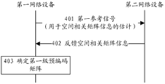
- FIG. 4 is a schematic flowchart diagram of a secondary precoding method according to an embodiment of the present application.
- the first network device sends a first reference signal to the second network device for estimation of spatial correlation matrix information.
- the first network device configuration can be used for reference signals for spatial correlation matrix information estimation and sent to the second network device.
- the first network device may send multiple sets of reference signals on different antenna ports according to structural features of the antenna array, so that the second network device measures channels corresponding to different antenna ports according to the received reference signals and calculates channels. Correlation matrix.
- the first network device may also send multiple sets of reference signals on the same or different antenna ports, and ensure that multiple beams used for transmitting the reference signals are orthogonal to each other, so that the second network device is based on the received reference signals.
- the spatial correlation matrix is measured.
- the specific form of the reference signal may be pre-agreed, for example, using CSI RS (Channel State Information Reference Signals) defined in the 3GPP (3rd Generation Partnership Project) TS 36.211 V13.1.0 protocol. ) or other reference signals that can meet the requirements, which is not limited in this application.
- CSI RS Channel State Information Reference Signals
- the second network device feeds back spatial correlation matrix information to the first network device.
- the second network device performs channel measurement according to the received reference signal, and feeds back spatial correlation matrix information to the first network device according to the channel measurement result.
- the spatial correlation matrix information may be channel correlation matrix information decomposed into different dimensions, such as a codeword index indicating a channel correlation matrix of different dimensions; or may be a codeword index directly indicating a spatial correlation matrix.
- the first network device determines the first level precoding matrix according to the spatial correlation matrix information fed back by the second network device.
- the first network device may determine the first level precoding matrix based on spatial correlation matrix information fed back by all of the second network devices in the area (eg, one cell) it serves.
- the first network device may calculate the first-level precoding matrix according to the capacity maximization criterion according to the spatial correlation matrix information of all the second network devices.
- the flexible first reference signal transmission mode can adapt to different hardware structures (such as DBF architecture, fully connected HBF architecture, partially connected HBF architecture, etc.), so that the secondary precoding system is under different hardware structures. Get better performance.
- the channel feedback solution provided by the present application for example, the embodiment corresponding to FIG. 4 above, can be applied to other systems that need to feedback user channel information, in addition to the secondary precoding system. This application does not limit this.
- the first network device sends a first reference signal to the second network device for estimation of spatial correlation matrix information.
- the first reference signal sent by the first network device includes: a set of reference signals transmitted on the N 1 antenna ports and a set of reference signals transmitted on the 2N 2 antenna ports, where N 1 is The number of antenna elements in the same polarization direction in each column of the antenna array, the N 1 antenna ports are composed of N 1 antenna elements in the same polarization direction in the same column of the antenna array, and N 2 is the number of columns of the antenna array. 2N 2 antenna ports are composed of 2N 2 antenna elements in two polarization directions in the same row of the antenna array.
- the first network device sends a first configuration and the N 1 group of the reference signal transmitted from the antenna port for measuring vertical antenna array channel, provided this group coding matrix as the reference signal
- the first network device reconfigures and transmits a reference signal transmitted on the 2N 2 antenna ports to measure the horizontal antenna array channel, and the coding matrix C′′ of the group reference signal is at (1+iN 1 row, i+1 column) and (1+N 1 N 2 +iN 1 row, N 2 +i+1 column)
- the first reference signal sent by the first network device includes: a set of reference signals transmitted on 2N 1 antenna ports and a set of reference signals transmitted on N 2 antenna ports, where N 1 The number of antenna elements in the same polarization direction in each column of the antenna array.
- the 2N 1 antenna port is composed of 2N 1 antenna elements in two polarization directions in the same column of the antenna array, and N 2 is the number of columns of the antenna array.
- the N 2 antenna ports are composed of N 2 antenna elements in the same polarization direction in the same row of the antenna array.
- the specific configuration and transmission mode process is similar to the above example, except that the group reference signal selects 2N 1 dual-polarized antenna port for measuring the vertical antenna array channel, and selects N 1 single-polarized antenna ports for measuring the horizontal antenna.
- the array channel is selected, and elements other than zero in C' and C" in this embodiment are selected correspondingly according to the rules in the above examples.
- the first reference signal sent by the first network device includes: a reference signal sent by the N/S group on the S antenna ports, and the reference signal sent by the N/S group on the S antenna ports
- the N beam directions are orthogonal to each other, where N is the number of antenna elements of the antenna array, S is the number of antenna ports, and S ⁇ N.
- the first network device configures and sends the precoded reference signal sent on the N/S group S antenna port to estimate the complete physical channel, and estimates the actual physical channel H of the MxN dimension, where M is the user.
- M the number of antennas
- This type of reference signal can be applied to both the DBF architecture and the HBF architecture to support the use of a more flexible hardware architecture.
- the second network device estimates spatial correlation matrix information based on the received reference signal.
- the second network device receives, by the first network device, a first reference signal that includes a set of reference signals transmitted on the N 1 antenna ports and a set of reference signals transmitted on the 2N 2 antenna ports,
- a first reference signal that includes a set of reference signals transmitted on the N 1 antenna ports and a set of reference signals transmitted on the 2N 2 antenna ports
- selecting an optimal codeword in the second codebook The selection may be based on the minimum distance criterion or other criteria, which is not limited in this application.
- the codewords in the first codebook are designed as n 1 ⁇ n 1 Hermitian matrices:
- the codewords in the second codebook are designed as n 2 ⁇ n 2 Hermitian matrices:
- n 2 is the number of antenna elements in the same polarization direction in the cross-polarized antenna array
- the cross-polarized antenna array is composed of antenna elements of two polarization directions in the same row or in the same column in the antenna array.
- the first network device may indicate, by signaling, a codebook of the quantized channel correlation matrix that the second network device needs to use, without notifying whether the reference signal currently sent by the second network device is a horizontal antenna array or a vertical antenna array.
- the first network device indicates, to the second network device, a codebook type used by each group of reference signals by using 1-bit RRC (Radio Resource Control) higher layer signaling, for example, '0' indicates that the first codebook is used, 1' indicates the use of the second codebook.
- RRC Radio Resource Control
- the second network device receiving a first network device comprises a first reference signal sent by a set of reference signals transmitted over antenna ports 2N 1 and a set of reference signals transmitted over antenna ports N 2
- the method and process for estimating the spatial correlation matrix information by the second network device and the design of the first codebook and the second codebook are similar to the above examples, and are not described herein again, except that in this example, according to 2N 1
- the horizontal antenna array and the vertical antenna array are both single-polarized antenna arrays, and the solution provided by the embodiment of the present application can still be used.
- the difference is that the horizontal antenna array channel correlation matrix and the vertical antenna array channel correlation matrix at this time are both quantized using the first codebook described above.
- the second network device receives the reference signal sent by the N/S group sent by the first network device on the S antenna ports, and the reference signal sent by the N/S group on the S antenna ports
- the N beam directions are orthogonal to each other, where N is the number of antenna elements of the antenna array, S is the number of antenna ports, and S ⁇ N.
- N is the number of antenna elements of the antenna array
- S is the number of antenna ports
- S ⁇ N For specific configuration and transmission mode, refer to the description of the example in Section 501, and details are not described herein again.
- selecting the optimal codeword in the spatial correlation matrix codebook It can be selected according to the minimum distance criterion, or can be selected according to other criteria, which is not limited in this application.
- the first network device indicates to the user the transmit beam weight of the reference signal sent by the N/S group on the S antenna ports, the number of transmit antenna units N, and the number of horizontally polarized antenna units N 2 And the number of vertically polarized antenna elements N 1 so that the second network device is used to estimate the channel H and determine the optimal codeword in the spatial correlation matrix codebook
- the spatial correlation matrix codebook is designed as a Kronecker Product of the first codebook and the second codebook, ie among them with
- the design of the codebook is the same as the example described above.
- each RRU Remote Radio Unit
- word (Subscript i denotes the codeword of the spatial correlation matrix of different RRU feedbacks)
- the codeword of the spatial correlation matrix For all of the above A Hermitian matrix of block diagonal structures.
- the second network device feeds back the spatial correlation matrix information to the first network device.
- the spatial correlation matrix information includes a codeword index of a first codebook and a codeword index of a second codebook.
- the second network device determines a codeword index of the first codebook and the second codebook according to channel measurements of different dimensions and feeds back to the first network device.
- the second network device measures complete channel information and codewords of the spatial correlation matrix And according to Determining a codeword index of the first codebook and the second codebook and feeding back to the first network device. Determining, by the first network device, the codewords of the first codebook and the second codebook according to the codeword index of the first codebook and the second codebook, and then according to Determine the codeword of the spatial correlation matrix.
- the spatial correlation matrix information includes a codeword index of a spatial correlation matrix.
- the second network device determines the codewords of the first codebook and the second codebook according to channel measurements of different dimensions, and according to A codeword index of the spatial correlation matrix is determined and fed back to the first network device.
- the second network device measures complete channel information and codewords of the spatial correlation matrix The codeword index of the spatial correlation matrix is fed back to the first network device.
- the first network device determines a codeword of the spatial correlation matrix based on a codeword index of the spatial correlation matrix.
- the first network device determines the first level precoding matrix according to the spatial correlation matrix information fed back by the second network device.
- the first network device may determine the first level precoding matrix based on spatial correlation matrix information fed back by all of the second network devices in the area (eg, one cell) it serves.
- the first network device may calculate the first-level precoding matrix according to the capacity maximization criterion according to the spatial correlation matrix information of all the second network devices.
- the first level precoding matrix determined by the first network device may be directly obtained by calculation according to spatial correlation matrix information, or may be calculated and quantized according to spatial correlation matrix information, for example, according to the calculation result.
- the optimal codeword is selected as the first level precoding matrix in the first level precoding codebook.
- the first network device transmits a second reference signal that is precoded by the first stage to the second network device.
- the second reference signal is used for the determination of the coding matrix indication by the second stage.
- the specific form of the second reference signal may be pre-defined, for example, using the CSI RS defined in the 3GPP TS 36.211 V13.1.0 protocol or other reference signals that can meet the requirements, which is not limited in this application.
- the second network device determines a second level precoding matrix indication based on the received second reference signal.
- the second network device can determine the second level precoding matrix indication using a prior art scheme.
- the technical solution for determining the second-level precoding matrix indication in the existing LTE system may be selected in the codebook for PMI (Precoding Matrix Indicator) feedback defined in the 3GPP TS 36.211 V13.1.0 protocol. A specific codeword and determining the second level precoding matrix indication.
- PMI Precoding Matrix Indicator
- the second network device determines the second level precoding matrix indication in conjunction with the equivalent channel correlation matrix and the second reference signal.
- an adaptive codebook structure based on an equivalent channel correlation matrix is an equivalent channel correlation matrix
- the codebook of the codeword W′ may be a DFT (Discrete Fourier Transform) codebook or a PMI (Precoding Matrix Indicator) feedback defined in the 3GPP TS 36.211 V13.1.0 protocol.
- the codebook may also be in other forms of codebook form that can characterize channel information.
- Adaptive codebook structure based on equivalent channel correlation matrix The definition can better describe the correlation characteristics of the downlink equivalent channel and improve the accuracy of the second-level precoding matrix, thereby improving the performance of the secondary precoding system.
- the second network device may receive the indication of the first network device, and determine, according to the indication, whether the adaptive codebook structure based on the equivalent channel correlation matrix is provided by using the embodiment of the present application.
- the first network device indicates, by using 1-bit RRC (Radio Resource Control) higher layer signaling, an adaptive codebook structure based on an equivalent channel correlation matrix to the second network device, for example, '0' indicates that the current use is used.
- RRC Radio Resource Control
- the codebook defined in the 3GPP protocol, ie '1' indicates the use of an adaptive codebook form containing an equivalent channel correlation matrix
- the first network device transmits first level precoding matrix information to the second network device for determination of the second level precoding matrix indication.
- the first network device determines, in the first-level precoding codebook, the codeword corresponding to the first-level precoding matrix; the first network device sends the codeword index corresponding to the first-level precoding matrix to the second network device.
- the first network device and the second network device both correspond to the codewords in the first level precoding codebook according to the first level precoding matrix.
- Codewords of the spatial correlation matrix obtained in Section 502 Or the codewords of the first codebook and the second codebook to calculate an equivalent channel correlation matrix
- the second network device determines a rank r (Rank) according to the received second reference signal and an equivalent channel correlation matrix, and a codeword W' in the codebook representing the short-term narrowband channel feature corresponding to the rank r, and
- the codeword index of W' is fed back to the first network device as the second level precoding matrix indication.
- the second level precoding matrix indication may also be fed back to the first network device together with channel information such as RI (Rank Indication) and/or CQI (Channel Quality Indicator).
- the second network device estimates a corresponding codeword in the first level precoding matrix in the first level precoding matrix; the second network device is in accordance with the estimated first level precoding matrix. Determining, by the corresponding codeword in the primary precoding codebook and the second reference signal, the second level precoding matrix indication.
- the second network device estimates an unquantized equivalent channel correlation matrix based on the measured equivalent channel H eff Then estimating the codeword corresponding to the first level precoding matrix in the first level precoding codebook ⁇
- the estimating a codeword corresponding to the first-level precoding matrix may be adopted, or other criteria may be adopted. This application does not limit this. The following uses the minimum distance criterion as an example. Estimated way.
- the second network device can learn the codeword of the quantized spatial correlation matrix When estimated, it can be estimated according to the following formula
- part 502 when the second network device can learn the unquantized spatial correlation matrix R, it can be estimated according to the following formula.
- the second network device is based on the estimate Calculate the equivalent channel correlation matrix
- the second network device determines a rank r (Rank) according to the received second reference signal and an equivalent channel correlation matrix, and a codeword W' in the codebook representing the short-term narrowband channel feature corresponding to the rank r, and The codeword index of W' is fed back to the first network device as the second level precoding matrix indication.
- the second level precoding matrix indication may also be fed back to the first network device together with channel information such as RI (Rank Indication) and/or CQI (Channel Quality Indicator).
- the codeword in the first stage precoding codebook ⁇ Can be a non-block diagonal structure:
- v 1 -v s are N ⁇ 1 dimensional mutually different column vectors, selected from a predefined codebook that can be indicated by Q1 bit cells, such as DFT codebook, Kronecker codebook or 3GPP TS 36.211
- Q1 bit cells such as DFT codebook, Kronecker codebook or 3GPP TS 36.211
- the codebook defined in the V13.1.0 protocol is not limited in this application.
- the codeword in the first stage precoding codebook ⁇ can be indicated by a Q1S bit cell.
- the codeword in the first stage precoding codebook ⁇ Can be a block diagonal structure:
- v 1 -v s is a (N/S) ⁇ 1 dimensional column vector selected from a predefined codebook that can be indicated by a Q2 bit cell, such as a DFT codebook, a Kronecker codebook or a 3GPP TS 36.211
- the codebook defined in the V13.1.0 protocol is not limited in this application.
- the codeword in this ⁇ can be indicated by a Q2-bit cell.
- the first network device may indicate, by using 1-bit signaling, a type of the first-level pre-coded codebook selected by the second network device, for example, '0' indicates that the non-block diagonal structure codebook is used, and '1 'Represents the block diagonal structure codebook described above.
- the codeword form of the first-level pre-encoded codebook provided by the embodiment of the present application can be implemented in the embodiment of the present application.
- the secondary precoding method is applied to different hardware architectures to improve the performance of the secondary precoding system by selecting a better hardware architecture.
- a non-block diagonal structure codebook can be applied to the DBF architecture or full connection.
- the HBF architecture, the block diagonal structure codebook can be applied to the partially connected HBF architecture or the DBF architecture.
- the block diagonal structure codebook can also support the application of the embodiment of the present application in the distributed antenna system.
- the second network device feeds back a second level precoding matrix indication.
- the second network device can perform feedback of the second level precoding matrix indication using existing signaling and cells in the system, for example, in an LTE system, according to the provisions of 3GPP TS 36.211 V13.1.0.
- the second-stage precoding matrix indicates that the PMI is fed back through the PUCCH (Physical Uplink Control Channel) and/or the PUSCH (Physical Uplink Shared Channel), and signaling or cells may be added.
- the feedback indicated by the second level precoding matrix is not limited in this application.
- the second network device may separately feed back the second level precoding matrix indication, or may also feed back the RI (Rank Indication) and/or the CQI (Channel Quality) while feeding back the second level precoding matrix indication.
- Channel information such as Indicator, Channel Quality Indicator), which is not limited in this application.
- the first network device determines the second level precoding matrix according to the second level precoding matrix indication.
- the first network device is configured according to a codeword corresponding to the first level precoding matrix Codewords of spatial correlation matrices Determining the equivalent channel correlation matrix Determining a codeword W' according to a second-level precoding matrix indication reported by the second network device; according to an adaptive codebook structure based on an equivalent channel correlation matrix Determining an adaptive codeword of the second network device; and determining a final second-level precoding matrix according to the adaptive codewords of the plurality of second network devices.
- the first network device may use a traditional MU-MIMO (Multi User Multiple Input Multiple Output) technology based on equivalent channel information, including user scheduling and precoding algorithms such as ZF (Zero Forcing, The zero-forcing algorithm or the like determines the second-level pre-coding matrix, and the plurality of second network devices may be determined according to a user scheduling algorithm, or may be determined according to other criteria, which is not limited in this application.
- MU-MIMO Multi User Multiple Input Multiple Output
- ZF Zero-forcing
- the zero-forcing algorithm or the like determines the second-level pre-coding matrix
- the plurality of second network devices may be determined according to a user scheduling algorithm, or may be determined according to other criteria, which is not limited in this application.
- the first network device is based on the first level precoding matrix C and the codeword of the spatial correlation matrix. Determining the equivalent channel correlation matrix Determining a codeword W' according to a second-level precoding matrix indication reported by the second network device; according to an adaptive codebook structure based on an equivalent channel correlation matrix Determining an adaptive codeword of the second network device; and determining a final second-level precoding matrix according to the adaptive codewords of the plurality of second network devices.
- sections 505-508 can also be independently applied to a system that needs to feed back a channel correlation matrix and determine a precoding matrix, and is not limited to the first level precoding provided by the embodiment of the present application.
- the determination method ie, sections 501-504 is used in combination.
- the first network device precodes the downlink data using the first level and second level precoding matrices.
- the first network device sends the second-level precoded downlink data to the second network device.
- FIG. 6 is a schematic diagram showing a possible structure of the first network device involved in the foregoing embodiment.
- the first network device includes a transmitter, a receiver, and a processor in its structure.
- the first network device may also include an interface unit in the structure for supporting communication with other first network devices, such as communication with a core network node.
- the first network device involved in the present application includes a transmitter 601, a receiver 602, a processor 603, and a memory 604.
- the transmitter 601 and the receiver 602 are configured to support transmission and reception of information between the first network device and the second network device in the foregoing embodiment.
- the processor 603 performs various functions for communicating with a second network device.
- the processor 603 also performs the processing involved in the first network device in Figures 4 and 5.
- the memory 604 is used to store program codes and data of the first network device.
- Figure 6 only shows a simplified design of the first network device.
- the first network device may include any number of transmitters, receivers, processors, memories, etc., and all of the first network devices that can implement the present application are within the scope of the present application.
- the first network device may be a base station or other network side device with a base station function.
- Fig. 7 shows a simplified schematic diagram of one possible design structure of the second network device involved in the above embodiment.
- the structure of the second network device includes a transmitter, a receiver, and a processor.
- the structure of the second network device involved in the present application includes a transmitter 701, a receiver 702, a processor 703, and a memory 704.
- the traffic or signaling data to be transmitted is processed by the transmitter 701 to generate an uplink signal, which is transmitted to the first network device described in the above embodiment via the antenna.
- the antenna receives the downlink signal transmitted by the first network device in the above embodiment, and the receiver 702 processes the signal received from the antenna and transmits it to other devices or modules that require further processing of the signal, such as a processor. .
- the service data and the signaling message are processed. These units are processed according to the radio access technology employed by the radio access network (e.g., access technologies of LTE and other evolved systems).
- the processor 703 is further configured to perform control and management on the action of the second network device, where the processing performed by the second network device in the foregoing embodiment is performed, for example, to control the second network device to receive downlink information, and/or according to The received downlink information carries out other processes of the techniques described herein.
- the processor 703 is configured to support the second network device to perform the processing procedure involving the second network device in FIG. 4 and FIG. 5.
- the memory 704 is configured to store program codes and data for the second network device.
- the second network device may be a user equipment.
- the steps of a method or algorithm described in connection with the present disclosure may be implemented in a hardware or may be implemented by a processor executing software instructions.
- the software instructions may be comprised of corresponding software modules that may be stored in RAM memory, flash memory, ROM memory, EPROM memory, EEPROM memory, registers, hard disk, removable hard disk, CD-ROM, or any other form of storage well known in the art.
- An exemplary storage medium is coupled to the processor to enable the processor to read information from, and write information to, the storage medium.
- the storage medium can also be an integral part of the processor.
- the processor and the storage medium can be located in an ASIC. Additionally, the ASIC can be located in the first network device or the second network device.
- the processor and the storage medium may also exist as a discrete component in the first network device or the second network device.
- some or all of the steps of the method or algorithm described in the present application may also be implemented by means of a chip system, the chip system comprising at least one chip.
- the chip system may also include other discrete devices.
- the functions described herein can be implemented in hardware, software, firmware, or any combination thereof.
- the functions may be stored in a computer readable medium or transmitted as one or more instructions or code on a computer readable medium.
- Computer readable media includes both computer storage media and communication media including any medium that facilitates transfer of a computer program from one location to another.
- a storage medium may be any available media that can be accessed by a general purpose or special purpose computer.
Landscapes
- Engineering & Computer Science (AREA)
- Signal Processing (AREA)
- Computer Networks & Wireless Communication (AREA)
- Physics & Mathematics (AREA)
- Mathematical Physics (AREA)
- Radio Transmission System (AREA)
Priority Applications (2)
| Application Number | Priority Date | Filing Date | Title |
|---|---|---|---|
| EP17795625.7A EP3444960B1 (de) | 2016-05-13 | 2017-05-12 | Verfahren und vorrichtung zur zweistufigen vorcodierung |
| US16/186,831 US10630353B2 (en) | 2016-05-13 | 2018-11-12 | Two-stage precoding method and apparatus |
Applications Claiming Priority (2)
| Application Number | Priority Date | Filing Date | Title |
|---|---|---|---|
| CN201610323177.4 | 2016-05-13 | ||
| CN201610323177.4A CN107395259B (zh) | 2016-05-13 | 2016-05-13 | 一种二级预编码方法及装置 |
Related Child Applications (1)
| Application Number | Title | Priority Date | Filing Date |
|---|---|---|---|
| US16/186,831 Continuation US10630353B2 (en) | 2016-05-13 | 2018-11-12 | Two-stage precoding method and apparatus |
Publications (1)
| Publication Number | Publication Date |
|---|---|
| WO2017194007A1 true WO2017194007A1 (zh) | 2017-11-16 |
Family
ID=60266306
Family Applications (1)
| Application Number | Title | Priority Date | Filing Date |
|---|---|---|---|
| PCT/CN2017/084184 WO2017194007A1 (zh) | 2016-05-13 | 2017-05-12 | 一种二级预编码方法及装置 |
Country Status (4)
| Country | Link |
|---|---|
| US (1) | US10630353B2 (de) |
| EP (1) | EP3444960B1 (de) |
| CN (1) | CN107395259B (de) |
| WO (1) | WO2017194007A1 (de) |
Cited By (1)
| Publication number | Priority date | Publication date | Assignee | Title |
|---|---|---|---|---|
| US20220038145A1 (en) * | 2019-03-29 | 2022-02-03 | Huawei Technologies Co., Ltd. | Communication method and apparatus |
Families Citing this family (7)
| Publication number | Priority date | Publication date | Assignee | Title |
|---|---|---|---|---|
| CN107733493B (zh) * | 2016-08-10 | 2021-02-12 | 华为技术有限公司 | 用于确定预编码矩阵的方法和装置 |
| JP2019118039A (ja) * | 2017-12-27 | 2019-07-18 | 富士通株式会社 | 基地局装置、スケジューリング方法、及び無線通信システム |
| CN108306698B (zh) * | 2017-12-29 | 2021-04-09 | 上海华为技术有限公司 | 一种下行信道测量的方法及装置 |
| CN110855340A (zh) * | 2019-11-11 | 2020-02-28 | 无锡北邮感知技术产业研究院有限公司 | 一种混合预编码方法及装置 |
| US10965386B1 (en) * | 2020-03-06 | 2021-03-30 | Rockwell Collins, Inc. | System and method for calibrating antenna array |
| CN113765549B (zh) * | 2020-06-03 | 2023-04-07 | 华为技术有限公司 | 通信方法及装置 |
| WO2022006778A1 (en) * | 2020-07-08 | 2022-01-13 | Zte Corporation | Systems and methods for codeword reporting by wireless communication device for uplink tranmissions |
Citations (6)
| Publication number | Priority date | Publication date | Assignee | Title |
|---|---|---|---|---|
| CN101442351A (zh) * | 2007-11-19 | 2009-05-27 | 电子科技大学 | 结合块对角化和统一信道分解反馈算法的多用户mimo系统 |
| WO2009128630A1 (en) * | 2008-04-17 | 2009-10-22 | Samsung Electronics Co., Ltd. | Apparatus and method for precoding by midamble in multiple input multiple output wireless communication system |
| US20110194631A1 (en) * | 2010-02-11 | 2011-08-11 | Samsung Electronics Co., Ltd. | Unified feedback frame for supporting a plurality of feedback modes and a multiple-input multiple-output (mimo) communication system using the unified feedback frame |
| CN102299775A (zh) * | 2010-06-24 | 2011-12-28 | 上海贝尔股份有限公司 | 一种预编码矩阵的选择方法和装置 |
| CN102725990A (zh) * | 2010-04-06 | 2012-10-10 | 上海贝尔股份有限公司 | 执行空间信息辅助的分级反馈的方法和设备 |
| CN105450343A (zh) * | 2014-08-30 | 2016-03-30 | 华为技术有限公司 | 一种预编码的方法、装置及系统 |
Family Cites Families (2)
| Publication number | Priority date | Publication date | Assignee | Title |
|---|---|---|---|---|
| CN102868479B (zh) * | 2011-07-07 | 2015-06-03 | 华为技术有限公司 | 多天线传输方法、装置及系统 |
| WO2017107002A1 (en) * | 2015-12-21 | 2017-06-29 | Orange | Method and device for beamforming |
-
2016
- 2016-05-13 CN CN201610323177.4A patent/CN107395259B/zh active Active
-
2017
- 2017-05-12 WO PCT/CN2017/084184 patent/WO2017194007A1/zh active Application Filing
- 2017-05-12 EP EP17795625.7A patent/EP3444960B1/de active Active
-
2018
- 2018-11-12 US US16/186,831 patent/US10630353B2/en active Active
Patent Citations (6)
| Publication number | Priority date | Publication date | Assignee | Title |
|---|---|---|---|---|
| CN101442351A (zh) * | 2007-11-19 | 2009-05-27 | 电子科技大学 | 结合块对角化和统一信道分解反馈算法的多用户mimo系统 |
| WO2009128630A1 (en) * | 2008-04-17 | 2009-10-22 | Samsung Electronics Co., Ltd. | Apparatus and method for precoding by midamble in multiple input multiple output wireless communication system |
| US20110194631A1 (en) * | 2010-02-11 | 2011-08-11 | Samsung Electronics Co., Ltd. | Unified feedback frame for supporting a plurality of feedback modes and a multiple-input multiple-output (mimo) communication system using the unified feedback frame |
| CN102725990A (zh) * | 2010-04-06 | 2012-10-10 | 上海贝尔股份有限公司 | 执行空间信息辅助的分级反馈的方法和设备 |
| CN102299775A (zh) * | 2010-06-24 | 2011-12-28 | 上海贝尔股份有限公司 | 一种预编码矩阵的选择方法和装置 |
| CN105450343A (zh) * | 2014-08-30 | 2016-03-30 | 华为技术有限公司 | 一种预编码的方法、装置及系统 |
Cited By (2)
| Publication number | Priority date | Publication date | Assignee | Title |
|---|---|---|---|---|
| US20220038145A1 (en) * | 2019-03-29 | 2022-02-03 | Huawei Technologies Co., Ltd. | Communication method and apparatus |
| US11929799B2 (en) * | 2019-03-29 | 2024-03-12 | Huawei Technologies Co., Ltd. | Communication method and apparatus |
Also Published As
| Publication number | Publication date |
|---|---|
| EP3444960A4 (de) | 2019-04-10 |
| US20190081669A1 (en) | 2019-03-14 |
| EP3444960B1 (de) | 2023-10-11 |
| CN107395259A (zh) | 2017-11-24 |
| EP3444960A1 (de) | 2019-02-20 |
| CN107395259B (zh) | 2020-04-21 |
| US10630353B2 (en) | 2020-04-21 |
Similar Documents
| Publication | Publication Date | Title |
|---|---|---|
| US11671154B2 (en) | Methods and devices for determining precoder parameters in a wireless communication network | |
| CN108631847B (zh) | 传输信道状态信息的方法、终端设备和网络设备 | |
| CN107733493B (zh) | 用于确定预编码矩阵的方法和装置 | |
| JP6594443B2 (ja) | 基地局及びプリコーディングマトリックス決定方法 | |
| WO2017194007A1 (zh) | 一种二级预编码方法及装置 | |
| EP3963733A1 (de) | Verfahren und vorrichtungen zur csi-meldung in einem drahtloskommunikationssystem | |
| TWI538428B (zh) | 在網路中通信的方法、副站台及主站台 | |
| JP6583409B2 (ja) | 無線通信制御方法、無線通信システム、受信装置および送信装置 | |
| WO2016179801A1 (en) | Method and apparatus for channel state information feedback for full dimensional mimo | |
| CN111788785B (zh) | 一种预编码矩阵索引上报方法、通信装置及介质 | |
| WO2018094709A1 (zh) | 一种确定预编码矩阵的方法、装置及系统 | |
| CN115173909A (zh) | 用于频率参数化线性组合码本的码本子集限制 | |
| WO2019218317A1 (en) | Eigenvalue-based channel hardening and explicit feedback | |
| CN118120154A (zh) | 针对类型ii信道状态信息的信道状态信息省略 |
Legal Events
| Date | Code | Title | Description |
|---|---|---|---|
| NENP | Non-entry into the national phase |
Ref country code: DE |
|
| WWE | Wipo information: entry into national phase |
Ref document number: 2017795625 Country of ref document: EP |
|
| ENP | Entry into the national phase |
Ref document number: 2017795625 Country of ref document: EP Effective date: 20181114 |
|
| 121 | Ep: the epo has been informed by wipo that ep was designated in this application |
Ref document number: 17795625 Country of ref document: EP Kind code of ref document: A1 |