WO2017188647A2 - 보호회로모듈을 갖는 이차 전지 - Google Patents
보호회로모듈을 갖는 이차 전지 Download PDFInfo
- Publication number
- WO2017188647A2 WO2017188647A2 PCT/KR2017/004161 KR2017004161W WO2017188647A2 WO 2017188647 A2 WO2017188647 A2 WO 2017188647A2 KR 2017004161 W KR2017004161 W KR 2017004161W WO 2017188647 A2 WO2017188647 A2 WO 2017188647A2
- Authority
- WO
- WIPO (PCT)
- Prior art keywords
- circuit module
- tab
- cap plate
- terminal
- protection circuit
- Prior art date
- Legal status (The legal status is an assumption and is not a legal conclusion. Google has not performed a legal analysis and makes no representation as to the accuracy of the status listed.)
- Ceased
Links
Images




Classifications
-
- H—ELECTRICITY
- H01—ELECTRIC ELEMENTS
- H01M—PROCESSES OR MEANS, e.g. BATTERIES, FOR THE DIRECT CONVERSION OF CHEMICAL ENERGY INTO ELECTRICAL ENERGY
- H01M50/00—Constructional details or processes of manufacture of the non-active parts of electrochemical cells other than fuel cells, e.g. hybrid cells
- H01M50/50—Current conducting connections for cells or batteries
- H01M50/572—Means for preventing undesired use or discharge
- H01M50/574—Devices or arrangements for the interruption of current
- H01M50/581—Devices or arrangements for the interruption of current in response to temperature
-
- H—ELECTRICITY
- H01—ELECTRIC ELEMENTS
- H01M—PROCESSES OR MEANS, e.g. BATTERIES, FOR THE DIRECT CONVERSION OF CHEMICAL ENERGY INTO ELECTRICAL ENERGY
- H01M10/00—Secondary cells; Manufacture thereof
- H01M10/04—Construction or manufacture in general
- H01M10/0413—Large-sized flat cells or batteries for motive or stationary systems with plate-like electrodes
-
- H—ELECTRICITY
- H01—ELECTRIC ELEMENTS
- H01M—PROCESSES OR MEANS, e.g. BATTERIES, FOR THE DIRECT CONVERSION OF CHEMICAL ENERGY INTO ELECTRICAL ENERGY
- H01M10/00—Secondary cells; Manufacture thereof
- H01M10/05—Accumulators with non-aqueous electrolyte
- H01M10/052—Li-accumulators
-
- H—ELECTRICITY
- H01—ELECTRIC ELEMENTS
- H01M—PROCESSES OR MEANS, e.g. BATTERIES, FOR THE DIRECT CONVERSION OF CHEMICAL ENERGY INTO ELECTRICAL ENERGY
- H01M50/00—Constructional details or processes of manufacture of the non-active parts of electrochemical cells other than fuel cells, e.g. hybrid cells
- H01M50/50—Current conducting connections for cells or batteries
- H01M50/543—Terminals
-
- H—ELECTRICITY
- H01—ELECTRIC ELEMENTS
- H01M—PROCESSES OR MEANS, e.g. BATTERIES, FOR THE DIRECT CONVERSION OF CHEMICAL ENERGY INTO ELECTRICAL ENERGY
- H01M2200/00—Safety devices for primary or secondary batteries
- H01M2200/10—Temperature sensitive devices
- H01M2200/106—PTC
-
- Y—GENERAL TAGGING OF NEW TECHNOLOGICAL DEVELOPMENTS; GENERAL TAGGING OF CROSS-SECTIONAL TECHNOLOGIES SPANNING OVER SEVERAL SECTIONS OF THE IPC; TECHNICAL SUBJECTS COVERED BY FORMER USPC CROSS-REFERENCE ART COLLECTIONS [XRACs] AND DIGESTS
- Y02—TECHNOLOGIES OR APPLICATIONS FOR MITIGATION OR ADAPTATION AGAINST CLIMATE CHANGE
- Y02E—REDUCTION OF GREENHOUSE GAS [GHG] EMISSIONS, RELATED TO ENERGY GENERATION, TRANSMISSION OR DISTRIBUTION
- Y02E60/00—Enabling technologies; Technologies with a potential or indirect contribution to GHG emissions mitigation
- Y02E60/10—Energy storage using batteries
Definitions
- the present invention relates to a secondary battery, and more particularly to a secondary battery having a protective circuit module.
- a rechargeable battery is a battery that can be charged and discharged unlike a primary battery that is not rechargeable.
- Low-capacity secondary batteries are used in portable electronic devices such as mobile phones, notebook computers, and camcorders, and large-capacity batteries are widely used as power sources for driving motors in hybrid vehicles.
- Representative secondary batteries include nickel-cadmium (Ni-Cd) batteries, nickel-hydrogen (Ni-MH) batteries, lithium (Li) batteries, and lithium ion (Li-ion) secondary batteries.
- lithium ion secondary batteries have about three times higher operating voltage than nickel-cadmium batteries or nickel-hydrogen batteries, which are widely used as power sources for portable electronic equipment. In addition, it is widely used in view of high energy density per unit weight.
- the secondary battery mainly uses a lithium oxide as a positive electrode active material and a carbon material as a negative electrode active material.
- a battery is classified into a liquid electrolyte battery and a polymer electrolyte battery according to the type of electrolyte.
- a battery using a liquid electrolyte is called a lithium ion battery, and a battery using a polymer electrolyte is called a lithium polymer battery.
- One aspect of the present invention provides a secondary battery capable of reducing a height.
- a secondary battery is an electrode assembly having a first electrode, a second electrode, and a separator interposed between the first electrode and the second electrode, a case having a space in which the electrode assembly is accommodated, the case And a cap plate coupled to the opening formed in the cap plate, a terminal fixed to the cap plate, a protective circuit module stacked on the cap plate, and a safety member electrically connecting the protective circuit module and the terminal. Is spaced apart laterally from the side end of the protective circuit module.
- the safety member may include a first tab connected to the cap plate, a second tab connected to the protection circuit module, and a current blocking device interposed between the first tab and the second tab.
- the first tab and the second tab may protrude in the same direction and be stacked at intervals, and the terminal may be located between the protective circuit module and the safety member.
- the second tab may include a first opening formed on the first tab to expose the first tab, wherein the first tab is a base portion joined to the current blocking device and a connection portion bent at the base portion. It may include a terminal junction portion that is bent at the connection portion and bonded to the terminal.
- the base portion and the terminal junction portion may be disposed in parallel, and the terminal junction portion may be disposed above the base portion, and the second tab may be disposed on the first portion and the first portion bonded to the current blocking device. And a second portion connected to the second portion and a second portion having a larger width than the first portion and bonded to the protection circuit module, wherein the opening may be formed in the second portion.
- the second tab is bent from the first portion to connect the first portion and the second portion and the fourth portion and the fifth portion bent from the first portion to connect the second portion and the third portion It includes, and the fourth portion and the fifth portion may be arranged in parallel.
- the first tab and the second tab may protrude in different directions to be stacked at intervals, and the safety member may be located between the terminal and the protective circuit module.
- a first insulating film may be installed between the protective circuit module and the cap plate, and a second insulating film may be installed between the safety member and the cap plate.
- the protective circuit module and the cap may be bonded to the cap plate. Further comprising a connection member for connecting the plate, the protective circuit module may include a hole for exposing the connection member.
- the protective circuit module may have a length that is 1/3 to 2/3 of the length of the cap plate.
- the overall height may be reduced as compared with the conventional secondary battery.
- FIG. 1 is an exploded perspective view illustrating a rechargeable battery according to a first exemplary embodiment of the present invention.
- FIG. 2 is a cross-sectional view taken while the members shown in FIG. 1 are combined.
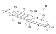
- FIG 3 is a perspective view showing a safety member according to a first embodiment of the present invention.
- FIG. 4 is a cross-sectional view taken along the line IV-IV of FIG. 3 of the present invention.
- FIG. 5 is a cross-sectional view of a rechargeable battery according to a second exemplary embodiment of the present invention.
- FIG. 6 is a perspective view showing a safety member according to a second embodiment of the present invention.
- FIG. 1 is an exploded perspective view illustrating a rechargeable battery according to a first exemplary embodiment of the present invention
- FIG. 2 is a cross-sectional view of the rechargeable battery when the members illustrated in FIG. 1 are combined.
- the secondary battery 101 includes an electrode assembly 10, a case 20, a cap plate 41, a protective circuit module 30, and a safety member ( 70).
- a rectangular battery is described as an example, the present invention is not limited thereto, and the present invention may be applied to various secondary batteries such as a pouch battery and a lithium polymer battery.
- the electrode assembly 10 includes an anode (first electrode) 11, a cathode (second electrode) 12, and a separator 13 disposed between the anode 11 and the cathode 12.
- the positive electrode 11 has a long stripe shape and includes a positive electrode coating portion, which is a region in which a positive electrode active material layer is formed, and a positive electrode non-coating portion, which is a region in which the active material is not coated.
- the positive electrode blank is located at one end in the longitudinal direction of the positive electrode.
- the negative electrode 12 has an elongated stripe shape and includes a negative electrode coating portion, which is a region in which a negative electrode active material layer is formed, and a negative electrode non-coating portion, which is a region in which the active material is not coated.
- the negative electrode uncoated portion is located at one end in the longitudinal direction of the negative electrode.
- the positive electrode 11 and the negative electrode 12 are wound up after being interposed between the separator 13 as an insulator, to form a jelly-roll.
- the present invention is not limited thereto, and the electrode assembly may be formed in a stacked structure in order so that a separator is interposed between the positive electrode and the negative electrode.
- the positive electrode tab 16 is fixed to the positive electrode 11, and the negative electrode tab 17 is fixed to the negative electrode 12.
- the positive electrode tab 16 and the negative electrode tab 17 are arranged parallel to the winding axis.
- the positive electrode tab 16 and the negative electrode tab 17 protrude in the direction in which the opening is formed in the case 20, and are spaced apart by a predetermined distance.
- the positive electrode tab 16 is made of an electrically conductive material such as nickel and aluminum, and is electrically connected to the cap plate 41.
- the negative electrode tab 17 is made of an electrically conductive material such as copper and nickel, and is electrically connected to the terminal 45.
- the case 20 has an opening 20a formed at an upper end thereof, and is formed of a box accommodating the electrode assembly 10.
- the case 20 provides a space for accommodating the electrode assembly 10 and the electrolyte therein and is electrically connected to the positive electrode tab 16.
- the case 20 may be manufactured by processing aluminum or an aluminum alloy by a method such as metal deep drawing.
- the cap plate 41 is coupled to the opening 20a of the case 20 to seal the case 20 and is made of an electrically conductive metal material such as aluminum or an aluminum alloy.
- the positive electrode tab 16 is joined to the lower surface of the cap plate 41 by welding, and the cap plate 41 and the case 20 are charged with the positive electrode.
- the upper insulating member 53 is installed between the electrode assembly 10 and the cap plate 41.
- the upper insulating member 53 includes a base 53a and a supporting wall 53b protruding from the side ends of the base 53a.
- the base 53a has a plate shape, and the base 53a is formed with a first tab hole 53d through which the positive electrode tab 16 penetrates and a second tab hole 53c through which the negative electrode tab 17 penetrates. have.
- the support wall 53b is formed to extend along the circumference of the base 53a.
- the terminal 45 is positioned at the center of the cap plate 41, and the cap plate 41 is formed with a terminal hole 48 into which the terminal 45 is inserted.
- the terminal 45 is installed on the cap plate 41 via the insulating gasket 46, and the insulating gasket 46 electrically insulates the terminal 45 and the cap plate 41 while surrounding the terminal 45. do.
- the terminal 45 is installed to penetrate the cap plate 41 and the connecting plate 52, and the connecting plate 52 is disposed between the electrode assembly 10 and the cap plate 41 inside the case 20.
- the connecting plate 52 has a plate shape and is disposed in parallel with the cap plate 41.
- the terminal 45 is fixed to the cap plate 41 and the connection plate 52 by riveting in a state where the terminal 45 is installed to penetrate the cap plate 41 and the connection plate 52.
- the negative electrode tab 17 is fixed to the connecting plate 52 by welding, so that the terminal 45 may be electrically connected to the negative electrode 12 via the connecting plate 52 and the negative electrode tab 17.
- An insulating plate 51 is provided between the cap plate 41 and the connecting plate 52 to insulate the connecting plate 52 from the cap plate 41.
- the insulating plate 51 is made of a plate having electrical insulation, and is disposed in parallel with the cap plate 41.
- the insulating plate 51 has a terminal hole 51a through which the terminal 45 passes.
- the connection plate 52 is formed in a plate shape extending in one direction, and the connection plate 52 has a terminal hole 52a through which the terminal 45 passes.
- the protection circuit module 30 may be installed on the cap plate 41 and may include a substrate 31 and circuit elements 32 mounted on the substrate 31.
- the protective circuit module 30 has a shorter length than the cap plate 41, and the length of the protective circuit module 30 may be 1/3 to 2/3 of the length of the cap plate 41.
- the lead terminal 35 is installed in the protection circuit module 30 and is electrically connected to the cap plate 41 through the connection member 38.
- the lead terminal 35 may be connected to an external device.
- the connecting member 38 is made of a bent metal plate and is welded to the cap plate 41.
- the protection circuit module 30 has a hole 36 exposing the connection member 38, and the connection member 38 may be welded to the cap plate 41 through the hole 36.
- the first insulating film 49 is installed between the protective circuit module 30 and the cap plate 41, the first insulating film 49 is the protective circuit module 30 and the cap plate 41 directly Prevent contact
- the first insulating film 49 includes a seating hole 49a into which the connecting member 38 is inserted.
- the secondary battery 101 further includes an upper cover 60 covering the protection circuit module 30, and the upper cover 60 may be fixed to the cap plate 41 by a screw or the like.
- the upper cover 60 includes a top plate 61 and a side wall 62 protruding from the top plate 61 toward the cap plate 41, and the side wall 62 surrounds the protective circuit module 30.
- the upper plate 61 is formed with a first through hole 63 and a second through hole 64, and the first through hole 63 is located above the terminal 45 and has an opening 726 formed in the safety member 70. 3, and the second through hole 64 is disposed above the hole 36 to communicate with the hole 36.
- FIG 3 is a perspective view showing a safety member according to a first embodiment of the present invention
- Figure 4 is a cross-sectional view taken along the line IV-IV in Figure 3 of the present invention.
- the protection circuit module 30 is also electrically connected to the terminal 45 via the safety member 70.
- the safety member 70 is disposed laterally spaced apart from the side end of the protection circuit module 30, the safety member 70 may be disposed in parallel with the protection circuit module 30.
- the safety member 70 is interposed between the first tab 71 connected to the terminal 45, the second tab 72 connected to the protection circuit module 30, and the first tab 71 and the second tab 72. And a current blocking element 75.
- the second insulating film 47 is installed between the safety member 70 and the cap plate 41, and the second insulating film 47 insulates the safety member 70 from the cap plate 41.
- the current blocking element 75 cuts off the current when an overcurrent flows.
- the current blocking device 75 may be a PTC device.
- the PTC device is a device in which the resistance increases as the temperature increases, and when the temperature of the secondary battery increases, the resistance is increased to block the current.
- the first tab 71 and the second tab 72 protrude in the same direction.
- the first tab 71 and the second tab 72 protrude in the direction toward the protection circuit module 30, and are stacked at intervals by the current blocking device 75.
- the terminal 45 is positioned between the safety member 70 and the protection circuit module 30.
- the safety member 70 is spaced apart in one direction at the side end of the terminal 45, and the protection circuit module 30 is spaced apart in the other direction at the side end of the terminal 45.
- the safety member 70 may be located on a side different from the protection circuit module 30 on the basis of the terminal 45.
- the safety member 70 may be sufficiently secured with an installation space of the protection circuit module 30. Minimize waste of space due to installation of
- the first tab 71 is bent from the base portion 711 and the base portion 711 bonded to the current blocking element 75 and the connecting portion 713 and the connecting portion 713 protruded upward, the terminal ( And a terminal joining portion 714 joined to 45.
- the base part 711 is disposed on the second insulating film 47, and the connection part 713 may be bent vertically upward from the base part 711.
- the terminal junction part 714 is bent at the connection part 713 and formed in parallel with the base part 711, and abuts on the upper surface of the terminal 45 to be welded to the terminal 45.
- the terminal junction portion 714 is disposed above the base portion 711.
- the second tab 72 is connected to the first portion 721 and the first portion 721 bonded to the current interrupting device 75 and has a larger width than the first portion 721. And a third portion 725 connected to the second portion 723 and bonded to the protection circuit module 30.
- the second tab 72 further includes an opening 726 formed in the second portion 723.
- the opening 726 is formed on the first tab 71 to expose the first tab 71, so that the first tab 71 and the terminal 45 can be easily joined through the opening 726. have.
- the laser may be irradiated to the terminal junction 714 through the opening 726, and a welding rod may be inserted into the opening 726 to weld the terminal junction 714 and the terminal 45 to each other.
- the second tab 72 is a fifth portion connecting the first portion 721 and the second portion 723 and a fifth portion connecting the second portion 723 and the third portion 725. It may include a portion 724.
- the fourth portion 722 is bent vertically upward from the first portion 721 such that the second portion 723 can be located above the first portion 721.
- the fifth portion 724 is bent vertically downward in the second portion 723.
- the third portion 725 may be located further below the second portion 723 and the first portion 721, and the third portion 725 may be disposed with the second portion 723 and the first portion 721. May be arranged in parallel.
- the fourth portion 722 and the fifth portion 724 may be arranged in parallel.
- the safety member 70 since the safety member 70 is disposed laterally spaced from the side end of the protection circuit module 30, the overall height of the secondary battery 101 may be reduced. In addition, since the first tab 71 and the second tab 72 protrude in the same direction, the installation space of the safety member 70 may be minimized. In addition, since the opening 726 is formed in the second tab 72, the first tab 71 can be easily welded to the terminal 45.
- FIGS. 5 and 6 are cross-sectional views illustrating a rechargeable battery according to a second exemplary embodiment of the present invention
- FIG. 6 is a perspective view illustrating a safety member according to a second exemplary embodiment of the present invention.
- the secondary battery 102 according to the second embodiment has the same structure as the secondary battery according to the first embodiment except for the safety member 80 and its installation position. Bar overlapping description of the same structure is omitted.
- the secondary battery 102 includes an electrode assembly 10 accommodated in the case 20, a cap plate 41 coupled to the case 20, and a protective circuit module disposed on the cap plate 41. 30) and the safety member 80.
- the terminal 45 is disposed in the cap plate 41, and the terminal 45 is disposed to be biased toward one side from the center of the cap plate 41.
- the terminals 45 are disposed in a direction opposite to the direction in which the protection circuit module 30 is located.
- the first insulating film 49 and the second insulating film 47 are attached to the cap plate 41, and the first insulating film 49 and the second insulating film 47 are cap plates based on the terminal 45. It is attached to both parts of the longitudinal direction of 41, respectively.
- the protection circuit module 30 and the safety member 80 are positioned on the first insulation film 49, and the first insulation film 49 includes the protection circuit module 30 and the safety member 80 with the cap plate 41. Insulate from The safety member 80 is laterally spaced apart from the side end of the protective circuit module 30, the safety member 80 may be disposed in parallel with the protective circuit module 30.
- the safety member 80 is interposed between the first tab 81 connected to the terminal 45, the second tab 82 connected to the protection circuit module 30, and the first tab 81 and the second tab 82. And a current interrupt device 83.
- the second insulating film 47 is installed between the safety member 80 and the cap plate 41, and the second insulating film 47 insulates the safety member 80 from the cap plate 41.
- the first tab 81 and the second tab 82 protrude in opposite directions, the first tab 81 protrudes toward the terminal, and the second tab 82 protrudes toward the protection circuit module 30. do.
- the safety member 80 is located between the terminal 45 and the protection circuit module 30. That is, the protection circuit module 30 is spaced apart in one direction from the side end of the safety member 80, the terminal 45 is spaced apart in the other direction from the side end of the safety member (80).
- the first tab 81 is bent from the base portion 811 and the base portion 811 joined to the current interruption element 83 and the base portion 811 protruding upward, and bent from the connection portion 813 to the terminal 45. And a terminal junction portion 815 joined thereto.
- connection part 813 is bent vertically upward from the base part 811, and the terminal junction part 815 is bent from the connection part 813 and disposed in parallel with the base part 811.
- the terminal junction part 815 is disposed above the base part 811, and abuts on the upper surface of the terminal 45 to be welded to the terminal 45.
- the second tab 82 includes a first portion 821 bonded to the current interrupting element 83 and a second portion 823 connected to the protection circuit module 30 and extending from the first portion 821. .
- the overall height of the secondary battery may be reduced.
- top cover 61 top plate
- connection part 714, 815 terminal connection part
Landscapes
- Chemical & Material Sciences (AREA)
- Chemical Kinetics & Catalysis (AREA)
- Electrochemistry (AREA)
- General Chemical & Material Sciences (AREA)
- Engineering & Computer Science (AREA)
- Manufacturing & Machinery (AREA)
- Connection Of Batteries Or Terminals (AREA)
- Battery Mounting, Suspending (AREA)
Abstract
본 발명의 일 측면은 높이를 감소시킬 수 있는 이차 전지를 제공한다. 본 발명의 일 실시예에 따른 이차 전지는 제1 전극, 제2 전극, 및 제1 전극과 제2 전극 사이에 개재된 세퍼레이터를 갖는 전극 어셈블리, 상기 전극 어셈블리가 수납되는 공간을 갖는 케이스, 상기 케이스에 형성된 개구에 결합된 캡 플레이트, 상기 캡 플레이트에 고정된 단자, 상기 캡 플레이트에 적층 배치된 보호회로모듈, 및 상기 보호회로모듈과 상기 단자를 전기적으로 연결하는 안전 부재를 포함하고, 상기 안전 부재는 상기 보호회로모듈의 측단에서 측방향으로 이격 배치된다.
Description
본 발명은 이차 전지에 관한 것으로서, 보다 상세하게는 보호회로모듈을 갖는 이차 전지에 관한 것이다.
이차 전지(rechargeable battery)는 충전이 불가능한 일차 전지와는 달리 충전 및 방전이 가능한 전지이다. 저용량의 이차 전지는 휴대폰이나 노트북 컴퓨터 및 캠코더와 같이 휴대가 가능한 소형 전자기기에 사용되고, 대용량 전지는 하이브리드 자동차 등의 모터 구동용 전원으로 널리 사용되고 있다.
대표적인 이차 전지에는 니켈-카드뮴(Ni-Cd)전지와 니켈-수소(Ni-MH)전지 및 리튬(Li) 전지와 리튬 이온(Li-ion) 이차 전지 등이 있다. 특히, 리튬 이온 이차 전지는 휴대용 전자 장비 전원으로 많이 사용되고 있는 니켈-카드뮴 전지나, 니켈-수소 전지보다 작동 전압이 약 3배나 높다. 또한, 단위 중량당 에너지 밀도가 높다는 측면에서 널리 사용되고 있다.
이차 전지는 주로 양극 활물질로 리튬계 산화물, 음극 활물질로는 탄소재를 사용하고 있다. 일반적으로는, 전해질의 종류에 따라 액체 전해질 전지와, 고분자 전해질 전지로 분류되며, 액체 전해질을 사용하는 전지를 리튬 이온 전지라 하고, 고분자 전해질을 사용하는 전지를 리튬 폴리머 전지라고 한다.
이차 전지는 용량을 증가시키는 것이 무엇보다 중요한데, 작은 부피의 이차 전지가 큰 용량을 갖는 것이 중요하다.
본 발명의 일 측면은 높이를 감소시킬 수 있는 이차 전지를 제공한다.
본 발명의 일 실시예에 따른 이차 전지는 제1 전극, 제2 전극, 및 제1 전극과 제2 전극 사이에 개재된 세퍼레이터를 갖는 전극 어셈블리, 상기 전극 어셈블리가 수납되는 공간을 갖는 케이스, 상기 케이스에 형성된 개구에 결합된 캡 플레이트, 상기 캡 플레이트에 고정된 단자, 상기 캡 플레이트에 적층 배치된 보호회로모듈, 및 상기 보호회로모듈과 상기 단자를 전기적으로 연결하는 안전 부재를 포함하고, 상기 안전 부재는 상기 보호회로모듈의 측단에서 측방향으로 이격 배치된다.
상기 안전 부재는 상기 캡 플레이트에 연결된 제1탭, 상기 보호회로모듈에 연결된 제2탭 및 상기 제1탭과 상기 제2탭 사이에 개재된 전류차단소자를 포함할 수 있다.
상기 제1탭과 제2탭은 동일한 방향으로 돌출되어 간격을 두고 적층될 수 있으며, 상기 단자는 상기 보호회로모듈과 상기 안전 부재 사이에 위치할 수 있다.
상기 제2탭은 제1탭 상에 형성되어 상기 제1탭을 노출시키는 제1 개구를 포함할 수 있으며, 상기 제1탭은 상기 전류차단소자에 접합된 베이스부와 상기 베이스부에서 절곡된 연결부, 상기 연결부에서 절곡되어 상기 상기 단자에 접합된 단자 접합부를 포함할 수 있다.
상기 베이스부와 상기 단자 접합부는 평행하게 배치되고, 상기 단자 접합부는 상기 베이스부보다 더 상부에 배치될 수 있으며, 상기 제2탭은 상기 전류차단소자에 접합된 제1부분과 상기 제1부분에 연결되며 상기 제1부분보다 더 큰 폭을 갖는 제2부분과 제2부분과 연결되며 보호회로모듈에 접합된 제3부분을 포함하고, 상기 개구는 상기 제2부분에 형성될 수 있다.
상기 제2탭은 상기 제1부분에서 절곡되어 상기 제1부분과 상기 제2부분을 연결하는 제4부분과 상기 제1부분에서 절곡되어 상기 제2부분과 상기 제3부분을 연결하는 제5부분을 포함하고, 상기 제4부분과 상기 제5부분은 평행하게 배치될 수 있다.
상기 제1탭과 제2탭은 서로 다른 방향으로 돌출되어 간격을 두고 적층될 수 있으며, 상기 안전 부재는 상기 단자와 상기 보호회로모듈 사이에 위치할 수 있다.
상기 보호회로모듈과 상기 캡 플레이트 사이에는 제1절연 필름이 설치되고, 상기 안전 부재와 상기 캡 플레이트 사이에는 제2절연 필름이 설치될 수 있으며, 상기 캡 플레이트에 접합되어 상기 보호회로모듈과 상기 캡 플레이트를 연결하는 연결부재를 더 포함하고, 상기 보호회로모듈은 상기 연결부재를 노출시키는 홀을 포함할 수 있다.
상기 보호회로모듈은 상기 캡 플레이트의 길이의 1/3 내지 2/3인 길이를 갖도록 이루어질 수 있다.
본 발명의 일 실시예에 따르면 안전 부재가 보호회로모듈의 측방향으로 이격 배치되므로 종래의 이차 전지에 비하여 전체 높이를 감소시킬 수 있다.
도 1은 본 발명의 제1 실시예에 따른 이차 전지를 도시한 분해 사시도이다.
도 2는 도 1에 도시된 부재들이 결합된 상태에서 잘라 본 단면도이다.
도 3은 본 발명의 제1 실시예에 따른 안전 부재를 도시한 사시도이다.
도 4는 본 발명의 도 3에서 Ⅳ-Ⅳ선을 따라 잘라 본 단면도이다.
도 5는 본 발명의 제2 실시예에 따른 이차 전지를 도시한 단면도이다.
도 6은 본 발명의 제2 실시예에 따른 안전 부재를 도시한 사시도이다.
이하, 첨부한 도면을 참고로 하여 본 발명의 실시예에 대하여 본 발명이 속하는 기술분야에서 통상의 지식을 가진 자가 용이하게 실시할 수 있도록 상세히 설명한다. 본 발명은 여러 가지 상이한 형태로 구현될 수 있으며 여기에서 설명하는 실시예에 한정되지 않는다.
도면에서 본 발명을 명확하게 설명하기 위해서 설명과 관계없는 부분은 생략하였으며, 명세서 전체를 통하여 동일 또는 유사한 구성요소에 대해서는 동일한 참조부호를 붙였다.
명세서 전체에서, 어떤 부분이 다른 부분과 "연결"되어 있다고 할 때, 이는 "직접적으로 연결"되어 있는 경우뿐 만 아니라, 다른 부재를 사이에 두고 "간접적으로 연결"된 것도 포함한다. 또한, 어떤 부분이 어떤 구성요소를 "포함"한다고 할 때, 이는 특별히 반대되는 기재가 없는 한 다른 구성요소를 제외하는 것이 아니라 다른 구성요소를 더 포함할 수 있는 것을 의미한다.
도 1은 본 발명의 제1 실시예에 따른 이차 전지를 도시한 분해 사시도이고, 도 2는 도 1에 도시된 부재들이 결합된 상태에서 잘라 본 단면도이다.
도 1 및 도 2를 참조하여 설명하면, 본 실시예에 따른 이차 전지(101)는 전극 어셈블리(10)와 케이스(20), 캡 플레이트(41), 보호회로모듈(30), 및 안전 부재(70)를 포함한다. 이하에서는 각형 전지를 예로써 설명하나, 본 발명이 이에 제한되는 것은 아니며, 본 발명은 파우치 전지, 리튬 폴리머 전지 등 다양한 이차 전지에 대하여 적용될 수 있다.
전극 어셈블리(10)는 양극(제1 전극)(11), 음극(제2 전극)(12) 및 양극(11)과 음극(12) 사이에 배치된 세퍼레이터(13)를 포함한다. 양극(11)는 길게 이어진 띠 형상으로 이루어지며, 양극 활물질층이 형성된 영역인 양극 코팅부와 활물질이 코팅되지 않는 영역인 양극 무지부를 포함한다. 양극 무지부는 양극의 길이방향 일측 단부에 위치한다.
음극(12)은 길게 이어진 띠 형상으로 이루어지며, 음극 활물질층이 형성된 영역인 음극 코팅부와 활물질이 코팅되지 않는 영역인 음극 무지부를 포함한다. 음극 무지부는 음극의 길이방향 일측 단부에 위치한다. 양극(11) 및 음극(12)은 절연체인 세퍼레이터(13)를 사이에 개재한 후 권취되어 젤리-롤 형태가 된다.
다만 본 발명이 이에 제한되는 것은 아니며, 전극 어셈블리는 양극과 음극 사이에 세퍼레이터가 개재되도록 차례로 적층된 구조로 이루어질 수 있다.
양극(11)에는 양극 탭(16)이 고정 설치되고, 음극(12)에는 음극 탭(17)이 고정 설치된다. 양극 탭(16)과 음극 탭(17)은 권회축과 평행하도록 배치된다. 양극 탭(16)과 음극 탭(17)은 케이스(20)에서 개구가 형성된 방향으로 돌출되며, 소정 거리 이격되어 있다.
양극 탭(16)은 니켈, 알루미늄과 같은 전기 전도성 재질로 이루어지며, 캡 플레이트(41)에 전기적으로 연결된다. 음극 탭(17)은 구리, 니켈과 같은 전기 전도성 재질로 이루어지며, 단자(45)와 전기적으로 연결된다.
케이스(20)는 상단에 개구부(20a)가 형성되어 전극 어셈블리(10)를 수용하는 상자로 이루어진다. 케이스(20)는 내부에 전극 어셈블리(10)와 전해액이 수용되는 공간을 제공하며, 양극 탭(16)과 전기적으로 연결된다. 케이스(20)는 알루미늄 또는 알루미늄 합금을 금속 딥 드로잉(deep drawing)과 같은 방법으로 가공하여 제작될 수 있다.
캡 플레이트(41)는 케이스(20)의 개구부(20a)에 결합되어 케이스(20)를 밀폐하며 알루미늄 또는 알루미늄 합금과 같은 전기 전도성 금속 재질로 이루어진다. 캡 플레이트(41)의 하면에는 양극 탭(16)이 용접으로 접합되어, 캡 플레이트(41)와 케이스(20)는 양극으로 대전된다.
전극 어셈블리(10)와 캡 플레이트(41) 사이에는 상부 절연부재(53)가 설치된다. 상부 절연부재(53)는 베이스(53a)와 베이스(53a)의 측단에서 돌출된 지지벽(53b)을 포함한다. 베이스(53a)는 판 형상으로 이루어지며, 베이스(53a)에는 양극 탭(16)이 관통하는 제1 탭 홀(53d)과 음극 탭(17)이 관통하는 제2 탭 홀(53c)이 형성되어 있다. 지지벽(53b)은 베이스(53a)의 둘레를 따라 이어져 형성된다.
단자(45)는 캡 플레이트(41)의 중앙에 위치하며, 캡 플레이트(41)에는 단자(45)가 삽입되는 단자 홀(48)이 형성된다. 단자(45)는 절연 개스킷(46)을 매개로 캡 플레이트(41)에 설치되며 절연 개스킷(46)은 단자(45)의 둘레를 감싸면서 단자(45)와 캡 플레이트(41)를 전기적으로 절연한다.
단자(45)는 캡 플레이트(41)와 접속 플레이트(52)를 관통하도록 설치되는데, 접속 플레이트(52)는 케이스(20)의 내부에서 전극 어셈블리(10)와 캡 플레이트(41) 사이에 배치된다. 접속 플레이트(52)는 판 형상으로 이루어지며, 캡 플레이트(41)와 평행하게 배치된다.
단자(45)는 캡 플레이트(41)와 접속 플레이트(52)를 관통하도록 설치된 상태에서 리벳팅에 의하여 캡 플레이트(41)와 접속 플레이트(52)에 고정된다. 음극 탭(17)은 접속 플레이트(52)에 용접으로 고정되며 이에 따라 단자(45)는 접속 플레이트(52)와 음극 탭(17)을 매개로 음극(12)과 전기적으로 연결될 수 있다.
캡 플레이트(41)와 접속 플레이트(52) 사이에는 접속 플레이트(52)를 캡 플레이트(41)에 대하여 절연하는 절연 플레이트(51)가 설치된다. 절연 플레이트(51)는 전기적인 절연성을 갖는 판으로 이루어지며, 캡 플레이트(41)와 평행하게 배치된다. 절연 플레이트(51)는 단자(45)가 관통하는 단자 홀(51a)을 갖는다. 접속 플레이트(52)는 일방향으로 길게 이어진 판상으로 이루어지며, 접속 플레이트(52)는 단자(45)가 관통하는 단자 홀(52a)을 갖는다.
보호회로모듈(30)은 캡 플레이트(41) 상에 설치되며, 기판(31)과 기판(31)에 실장된 회로소자들(32)을 포함할 수 있다. 보호회로모듈(30)은 캡 플레이트(41)보다 짧은 길이를 갖는데, 보호회로모듈(30)의 길이는 캡 플레이트(41)의 길이의 1/3 내지 2/3로 이루어질 수 있다.
보호회로모듈(30)에는 리드 단자(35)가 설치되며 연결부재(38)를 매개로 캡 플레이트(41)에 전기적으로 연결된다. 리드 단자(35)는 외부 기기와 연결될 수 있다. 연결부재(38)는 절곡된 금속판으로 이루어지며, 캡 플레이트(41)에 용접된다. 보호회로모듈(30)에는 연결부재(38)를 노출시키는 홀(36)이 형성되며, 홀(36)을 통해서 연결부재(38)를 캡 플레이트(41)에 용접할 수 있다.
한편, 보호회로모듈(30)과 캡 플레이트(41)에 사이에는 제1절연 필름(49)이 설치되는데, 제1절연 필름(49)은 보호회로모듈(30)과 캡 플레이트(41)가 직접 접촉하는 것을 방지한다. 제1절연 필름(49)은 연결부재(38)가 삽입되는 안착 홀(49a)을 포함한다.
이차 전지(101)는 보호회로모듈(30)을 덮는 상부 커버(60)를 더 포함하는데, 상부 커버(60)는 캡 플레이트(41)에 나사 등에 의하여 고정될 수 있다. 상부 커버(60)는 상판(61)과 상판(61)에서 캡 플레이트(41)를 향하여 돌출된 측벽(62)을 포함하며, 측벽(62)은 보호회로모듈(30)을 감싼다.
상판(61)에는 제1관통구(63)와 제2관통구(64)가 형성되며 제1관통구(63)는 단자(45)의 상부에 위치하며 안전 부재(70)에 형성된 개구(726, 도 3에 도시)와 연통되며 제2관통구(64)는 홀(36)의 상부에 배치되어 홀(36)과 연통된다.
도 3은 본 발명의 제1 실시예에 따른 안전 부재를 도시한 사시도이고, 도 4는 본 발명의 도 3에서 Ⅳ-Ⅳ선을 따라 잘라 본 단면도이다.
도 3 및 도 4를 참조하여 설명하면, 또한 보호회로모듈(30)은 안전 부재(70)를 매개로 단자(45)와 전기적으로 연결된다. 안전 부재(70)는 보호회로모듈(30)의 측단에서 측방향으로 이격 배치되는데, 안전 부재(70)는 보호회로모듈(30)과 평행하게 배치될 수 있다.
안전 부재(70)는 단자(45)에 연결된 제1탭(71), 보호회로모듈(30)에 연결된 제2탭(72) 및 제1탭(71)과 제2탭(72) 사이에 개재된 전류차단소자(75)를 포함한다. 안전 부재(70)와 캡 플레이트(41) 사이에는 제2절연 필름(47)이 설치되며, 제2절연 필름(47)은 안전 부재(70)와 캡 플레이트(41) 사이를 절연한다. 전류차단소자(75)는 과전류가 흐를 때 전류를 차단시킨다. 본 발명의 실시예에 따르면, 전류차단소자(75)는 PTC 소자일 수 있다. PTC 소자는 온도가 증가할수록 저항이 증가하는 소자로서 이차 전지의 온도가 상승하면 저항을 증가시켜서 전류를 차단한다.
제1탭(71)과 제2탭(72)은 동일한 방향으로 돌출되는데, 보호회로모듈(30)을 향하는 방향으로 돌출되어 전류차단소자(75)에 의하여 간격을 두고 적층된다. 제1탭(71)과 제2탭(72)이 동일한 방향으로 돌출되면 안전 부재(70)와 보호회로모듈(30) 사이에 단자(45)가 위치한다. 안전 부재(70)는 단자(45)의 측단에서 일 방향으로 이격 배치되고, 보호회로모듈(30)은 단자(45)의 측단에서 타 방향으로 이격 배치된다.
이에 따라 단자(45)를 기준으로 안전 부재(70)가 보호회로모듈(30)과 서로 다른 편에 위치할 수 있으며, 보호회로모듈(30)의 설치 공간을 충분히 확보하면서, 안전 부재(70)의 설치로 인한 공간의 낭비를 최소화할 수 있다.
한편, 제1탭(71)은 전류차단소자(75)에 접합된 베이스부(711)와 베이스부(711)에서 절곡되어 상부로 돌출된 연결부(713), 연결부(713)에서 절곡되어 단자(45)에 접합된 단자 접합부(714)를 포함한다. 베이스부(711)는 제2절연 필름(47) 상에 배치되며, 연결부(713)는 베이스부(711)에서 상부를 향하여 수직으로 절곡될 수 있다. 단자 접합부(714)는 연결부(713)에서 절곡되어 베이스부(711)와 평행하게 형성되며 단자(45)의 상면과 맞닿아 단자(45)에 용접된다. 단자 접합부(714)는 베이스부(711)보다 더 상부에 배치된다.
제2탭(72)은 전류차단소자(75)에 접합된 제1부분(721)과 제1부분(721)에 연결되며 제1부분(721)보다 더 큰 폭을 갖는 제2부분(723), 및 제2부분(723)과 연결되며 보호회로모듈(30)에 접합된 제3부분(725)을 포함한다.
제2탭(72)은 제2부분(723)에 형성된 개구(726)를 더 포함한다. 개구(726)는 제1탭(71) 상에 형성되어 제1탭(71)을 노출시키며, 이에 따라 개구(726)를 통해서 제1탭(71)과 단자(45)를 용이하게 접합할 수 있다. 개구(726)를 통해서 단자 접합부(714)에 레이저가 조사될 수 있으며, 용접봉이 개구(726)에 삽입되어 단자 접합부(714)와 단자(45)가 용접될 수도 있다.
또한, 제2탭(72)은 제1부분(721)과 제2부분(723)을 연결하는 제4부분(722)과 제2부분(723)과 제3부분(725)을 연결하는 제5부분(724)을 포함할 수 있다. 제4부분(722)은 제1부분(721)에서 상부를 향하여 수직으로 절곡되며 이에 따라 제2부분(723)은 제1부분(721)보다 더 위에 위치할 수 있다. 제5부분(724)은 제2부분(723)에서 하부를 향하여 수직으로 절곡된다.
제3부분(725)은 제2부분(723) 및 제1부분(721)보다 더 아래에 위치할 수 있으며, 제3부분(725)은 제2부분(723) 및 제1부분(721)과 평행하게 배치될 수 있다. 또한, 제4부분(722)과 제5부분(724)은 평행하게 배치될 수 있다.
상기한 바와 같이 제1실시예에 따르면 안전 부재(70)가 보호회로모듈(30)의 측단에서 측방향으로 이격 배치되므로 이차 전지(101)의 전체 높이를 감소시킬 수 있다. 또한, 제1탭(71)과 제2탭(72)이 동일한 방향으로 돌출되므로 안전 부재(70)의 설치 공간을 최소화할 수 있다. 또한, 제2탭(72)에 개구(726)가 형성되므로 제1탭(71)을 단자(45)에 용이하게 용접할 수 있다.
이하에서는 도 5 및 도 6을 참조하여 제2 실시예에 따른 이차 전지에 대해서 설명한다. 도 5는 본 발명의 제2 실시예에 따른 이차 전지를 도시한 단면도이고, 도 6은 본 발명의 제2 실시예에 따른 안전 부재를 도시한 사시도이다.
도 5 및 도 6을 참조하면, 본 제2 실시예에 따른 이차 전지(102)는 안전 부재(80)와 이의 설치 위치를 제외하고는 상기한 제1 실시예에 따른 이차 전지와 동일한 구조로 이루어지는바, 동일한 구조에 대한 중복 설명은 생략한다.
이차 전지(102)는 케이스(20)에 케이스(20)에 수납된 전극 어셈블리(10), 케이스(20)에 결합된 캡 플레이트(41), 캡 플레이트(41) 상에 배치된 보호회로모듈(30)과 안전 부재(80)를 포함한다.
캡 플레이트(41)에는 단자(45)가 배치되는데, 단자(45)는 캡 플레이트(41)의 중심에서 일측으로 치우쳐 배치된다. 단자(45)는 보호회로모듈(30)이 위치하는 방향의 반대방향으로 치우쳐 배치된다. 캡 플레이트(41)에는 제1절연 필름(49)과 제2절연 필름(47)이 부착되며, 제1절연 필름(49)과 제2절연 필름(47)은 단자(45)를 기준으로 캡 플레이트(41)의 길이방향 양쪽 부분에 각각 부착된다.
제1절연 필름(49) 상에는 보호회로모듈(30)과 안전 부재(80)가 위치하며, 제1절연 필름(49)은 보호회로모듈(30)과 안전 부재(80)를 캡 플레이트(41)로부터 절연시킨다. 안전 부재(80)는 보호회로모듈(30)의 측단에서 측방향으로 이격 배치되는데 안전 부재(80)는 보호회로모듈(30)과 평행하게 배치될 수 있다.
안전 부재(80)는 단자(45)에 연결된 제1탭(81), 보호회로모듈(30)에 연결된 제2탭(82) 및 제1탭(81)과 제2탭(82) 사이에 개재된 전류차단소자(83)를 포함한다. 안전 부재(80)와 캡 플레이트(41) 사이에는 제2절연 필름(47)이 설치되며, 제2절연 필름(47)은 안전 부재(80)와 캡 플레이트(41) 사이를 절연한다.
제1탭(81)과 제2탭(82)은 서로 반대 방향으로 돌출되는데, 제1탭(81)은 단자를 향하여 돌출되고, 제2탭(82)은 보호회로모듈(30)을 향하여 돌출된다. 여기서 안전 부재(80)는 단자(45)와 보호회로모듈(30) 사이에 위치한다. 즉, 보호회로모듈(30)은 안전 부재(80)의 측단에서 일 방향으로 이격 배치되고, 단자(45)는 안전 부재(80)의 측단에서 타 방향으로 이격 배치된다.
제1탭(81)은 전류차단소자(83)에 접합된 베이스부(811)와 베이스부(811)에서 절곡되어 상부로 돌출된 연결부(813), 연결부(813)에서 절곡되어 단자(45)에 접합된 단자 접합부(815)를 포함한다.
연결부(813)는 베이스부(811)에서 상부를 향하여 수직으로 절곡되며, 단자 접합부(815)는 연결부(813)에서 절곡되어 베이스부(811)와 평행하게 배치된다. 단자 접합부(815)는 베이스부(811)보다 더 상부에 배치되며, 단자(45)의 상면과 맞닿아 단자(45)에 용접된다. 제2탭(82)은 전류차단소자(83)에 접합된 제1부분(821)과 제1부분(821)에서 이어지며 보호회로모듈(30)에 접합된 제2부분(823)을 포함한다.
제2실시예와 같이 안전 부재(80)가 보호회로모듈에서 측방향으로 이격 배치되면 이차 전지의 전체 높이를 감소시킬 수 있다.
이상 본 발명의 바람직한 실시예에 대하여 설명하였지만, 본 발명이 이에 한정되는 것은 아니며 특허청구범위와 발명의 상세한 설명 및 첨부한 도면의 범위 안에서 여러 가지로 변형하여 실시할 수 있다.
- 부호의 설명 -
101, 102: 이차 전지 10: 전극 어셈블리
11: 양극 12: 음극
13: 세퍼레이터 16: 양극 탭
17: 음극 탭 20: 케이스
20a: 개구부 30: 보호회로모듈
31: 기판 32: 회로소자들
35: 리드 단자 36: 홀
38: 연결부재 41: 캡 플레이트
45: 단자 46: 절연 개스킷
47: 제2절연 필름 49: 제1절연 필름
49a: 안착 홀 51: 절연 플레이트
52: 접속 플레이트 53: 상부 절연부재
53a: 베이스 53b: 지지벽
60: 상부 커버 61: 상판
62: 측벽 63: 제1관통구
64: 제2관통구 70, 80: 안전 부재
71, 81: 제1탭 711, 811: 베이스부
713, 813: 연결부 714, 815: 단자 접합부
72, 82: 제2탭 721, 821: 제1부분
722: 제4부분 723, 823: 제2부분
724: 제5부분 725: 제3부분
726: 개구 75, 83: 전류차단소자
Claims (14)
- 제1 전극, 제2 전극, 및 제1 전극과 제2 전극 사이에 개재된 세퍼레이터를 갖는 전극 어셈블리;상기 전극 어셈블리가 수납되는 공간을 갖는 케이스;상기 케이스에 형성된 개구에 결합된 캡 플레이트;상기 캡 플레이트에 고정된 단자;상기 캡 플레이트에 적층 배치된 보호회로모듈; 및상기 보호회로모듈과 상기 단자를 전기적으로 연결하는 안전 부재;를 포함하고,상기 안전 부재는 상기 보호회로모듈의 측단에서 측방향으로 이격 배치된 이차 전지.
- 제1항에 있어서,상기 안전 부재는 상기 캡 플레이트에 연결된 제1탭, 상기 보호회로모듈에 연결된 제2탭 및 상기 제1탭과 상기 제2탭 사이에 개재된 전류차단소자를 포함하는 이차 전지.
- 제2항에 있어서,상기 제1탭과 제2탭은 동일한 방향으로 돌출되어 간격을 두고 적층된 이차 전지.
- 제3항에 있어서,상기 단자는 상기 보호회로모듈과 상기 안전 부재 사이에 위치하는 이차 전지.
- 제3항에 있어서,상기 제2탭은 제1탭 상에 형성되어 상기 제1탭을 노출시키는 제1 개구를 포함하는 이차 전지.
- 제5항에 있어서,상기 제1탭은 상기 전류차단소자에 접합된 베이스부와 상기 베이스부에서 절곡된 연결부, 상기 연결부에서 절곡되어 상기 상기 단자에 접합된 단자 접합부를 포함하는 이차 전지.
- 제6항에 있어서,상기 베이스부와 상기 단자 접합부는 평행하게 배치되고, 상기 단자 접합부는 상기 베이스부보다 더 상부에 배치된 이차 전지.
- 제5항에 있어서,상기 제2탭은 상기 전류차단소자에 접합된 제1부분과 상기 제1부분에 연결되며 상기 제1부분보다 더 큰 폭을 갖는 제2부분과 제2부분과 연결되며 보호회로모듈에 접합된 제3부분을 포함하고, 상기 개구는 제2부분에 형성된 이차 전지.
- 제8항에 있어서,상기 제2탭은 상기 제1부분에서 절곡되어 상기 제1부분과 상기 제2부분을 연결하는 제4부분과 상기 제1부분에서 절곡되어 상기 제2부분과 상기 제3부분을 연결하는 제5부분을 포함하고, 상기 제4부분과 상기 제5부분은 평행하게 배치된 이차 전지.
- 제9항에 있어서,상기 제1탭과 제2탭은 서로 다른 방향으로 돌출되어 간격을 두고 적층된 이차 전지.
- 제1항에 있어서,상기 안전 부재는 상기 단자와 상기 보호회로모듈 사이에 위치하는 이차 전지.
- 제1항에 있어서,상기 보호회로모듈과 상기 캡 플레이트 사이에는 제1절연 필름이 설치되고, 상기 안전 부재와 상기 캡 플레이트 사이에는 제2절연 필름이 설치된 이차 전지.
- 제1항에 있어서,상기 캡 플레이트에 접합되어 상기 보호회로모듈과 상기 캡 플레이트를 연결하는 연결부재를 더 포함하고, 상기 보호회로모듈은 상기 연결부재를 노출시키는 홀을 포함하는 이차 전지.
- 제1항 내지 제13항 중 어느 한 항에 있어서,상기 보호회로모듈은 상기 캡 플레이트의 길이의 1/3 내지 2/3인 길이를 갖는 이차 전지.
Applications Claiming Priority (2)
| Application Number | Priority Date | Filing Date | Title |
|---|---|---|---|
| KR10-2016-0050890 | 2016-04-26 | ||
| KR1020160050890A KR102623625B1 (ko) | 2016-04-26 | 2016-04-26 | 보호회로모듈을 갖는 이차 전지 |
Publications (2)
| Publication Number | Publication Date |
|---|---|
| WO2017188647A2 true WO2017188647A2 (ko) | 2017-11-02 |
| WO2017188647A3 WO2017188647A3 (ko) | 2018-08-02 |
Family
ID=60160882
Family Applications (1)
| Application Number | Title | Priority Date | Filing Date |
|---|---|---|---|
| PCT/KR2017/004161 Ceased WO2017188647A2 (ko) | 2016-04-26 | 2017-04-19 | 보호회로모듈을 갖는 이차 전지 |
Country Status (2)
| Country | Link |
|---|---|
| KR (1) | KR102623625B1 (ko) |
| WO (1) | WO2017188647A2 (ko) |
Cited By (1)
| Publication number | Priority date | Publication date | Assignee | Title |
|---|---|---|---|---|
| CN111433968A (zh) * | 2017-12-04 | 2020-07-17 | 三星Sdi株式会社 | 电池组 |
Families Citing this family (1)
| Publication number | Priority date | Publication date | Assignee | Title |
|---|---|---|---|---|
| JP7581372B2 (ja) * | 2021-04-02 | 2024-11-12 | 香港時代新能源科技有限公司 | エンドキャップアセンブリ、電池セル、電池及び電池セルの製造方法と機器 |
Family Cites Families (5)
| Publication number | Priority date | Publication date | Assignee | Title |
|---|---|---|---|---|
| JP4300768B2 (ja) * | 2002-08-06 | 2009-07-22 | パナソニック株式会社 | 電池装置 |
| EP1714334B1 (en) * | 2004-01-28 | 2017-11-08 | Lg Chem, Ltd. | Secondary battery of assemble-type structure |
| KR20080037864A (ko) * | 2006-10-27 | 2008-05-02 | 삼성에스디아이 주식회사 | 리튬 이차 전지 |
| KR101082865B1 (ko) * | 2007-11-29 | 2011-11-11 | 주식회사 엘지화학 | 도전성 패턴이 형성된 보호회로 기판을 포함하는 전지팩 |
| KR101450221B1 (ko) * | 2013-04-17 | 2014-10-15 | 주식회사 아이티엠반도체 | 배터리 보호회로 모듈 패키지 |
-
2016
- 2016-04-26 KR KR1020160050890A patent/KR102623625B1/ko active Active
-
2017
- 2017-04-19 WO PCT/KR2017/004161 patent/WO2017188647A2/ko not_active Ceased
Cited By (2)
| Publication number | Priority date | Publication date | Assignee | Title |
|---|---|---|---|---|
| CN111433968A (zh) * | 2017-12-04 | 2020-07-17 | 三星Sdi株式会社 | 电池组 |
| CN111433968B (zh) * | 2017-12-04 | 2023-09-19 | 三星Sdi株式会社 | 电池组 |
Also Published As
| Publication number | Publication date |
|---|---|
| KR20170121953A (ko) | 2017-11-03 |
| KR102623625B1 (ko) | 2024-01-09 |
| WO2017188647A3 (ko) | 2018-08-02 |
Similar Documents
| Publication | Publication Date | Title |
|---|---|---|
| WO2021125504A1 (ko) | 이차 전지 | |
| WO2018147603A1 (ko) | 이차 전지 | |
| WO2019050152A1 (ko) | 벤팅 가스를 이용하여 커넥터를 파단시키는 구조를 갖는 배터리 모듈 | |
| US9257691B2 (en) | Battery pack | |
| WO2015167046A1 (ko) | 이차 전지용 회로 기판 및 이를 포함하는 배터리 팩 | |
| WO2012077967A2 (ko) | 캡 조립체 및 이를 이용한 이차 전지 | |
| WO2018199439A1 (ko) | 이차 전지 | |
| WO2018203593A1 (ko) | 배터리 팩 및 이의 제조방법 | |
| WO2023113122A1 (ko) | 전해액 누액 검출기능이 구비된 전지 모듈 및 이를 포함하는 전지 팩 | |
| WO2018026105A1 (ko) | 이차 전지 | |
| WO2018212447A1 (ko) | 이차 전지 | |
| WO2022004987A1 (ko) | 이차 전지 | |
| WO2017188533A1 (ko) | 멤브레인을 갖는 이차 전지 | |
| WO2018088691A1 (ko) | 배터리 팩 | |
| WO2018004159A1 (ko) | 이차전지 | |
| WO2018056630A1 (ko) | 이차 전지 | |
| WO2018164389A1 (ko) | 이차 전지 | |
| WO2019050180A1 (ko) | 이차 전지 | |
| WO2023136496A1 (ko) | 안전성이 향상된 파우치형 전지 셀 및 이를 포함하는 전지 모듈 | |
| WO2023113424A1 (ko) | 이차 전지 | |
| WO2018080074A1 (ko) | 이차 전지 | |
| WO2017222199A1 (ko) | 이차 전지 | |
| WO2022071759A1 (ko) | 이차전지 및 이를 포함하는 디바이스 | |
| WO2021162238A1 (ko) | 레일형 소켓이 구비된 전지 모듈 및 이를 포함하는 전지 팩 | |
| WO2016039503A1 (ko) | 과전류 차단수단이 구비된 이차전지 |
Legal Events
| Date | Code | Title | Description |
|---|---|---|---|
| NENP | Non-entry into the national phase |
Ref country code: DE |
|
| 121 | Ep: the epo has been informed by wipo that ep was designated in this application |
Ref document number: 17789832 Country of ref document: EP Kind code of ref document: A2 |
|
| 122 | Ep: pct application non-entry in european phase |
Ref document number: 17789832 Country of ref document: EP Kind code of ref document: A2 |