WO2017187583A1 - 生体縫合装置 - Google Patents
生体縫合装置 Download PDFInfo
- Publication number
- WO2017187583A1 WO2017187583A1 PCT/JP2016/063303 JP2016063303W WO2017187583A1 WO 2017187583 A1 WO2017187583 A1 WO 2017187583A1 JP 2016063303 W JP2016063303 W JP 2016063303W WO 2017187583 A1 WO2017187583 A1 WO 2017187583A1
- Authority
- WO
- WIPO (PCT)
- Prior art keywords
- staple
- ejection hole
- staple ejection
- jaw
- living body
- Prior art date
- Legal status (The legal status is an assumption and is not a legal conclusion. Google has not performed a legal analysis and makes no representation as to the accuracy of the status listed.)
- Ceased
Links
- 0 *CC(C*)N=C Chemical compound *CC(C*)N=C 0.000 description 2
Images





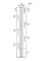
Classifications
-
- A—HUMAN NECESSITIES
- A61—MEDICAL OR VETERINARY SCIENCE; HYGIENE
- A61B—DIAGNOSIS; SURGERY; IDENTIFICATION
- A61B17/00—Surgical instruments, devices or methods
- A61B17/068—Surgical staplers, e.g. containing multiple staples or clamps
Definitions
- the present invention relates to a biological suturing device.
- a living body suturing device that joins living tissues by applying energy and reinforces the joining strength by stapling is known (for example, see Patent Document 1).
- a living body suturing device (electrosurgical tool) described in Patent Document 1 includes a long first jaw (jaw member) having a first clamping surface, and the first clamping surface facing the first clamping surface. And a long second jaw (jaw member) having a second clamping surface for clamping the living tissue therebetween.
- the first jaw is provided with a structure for driving staples into the living tissue.
- the second jaw is provided with a pair of electrodes for applying energy to the living tissue.
- the living body suturing device described in Patent Document 1 employs the following structure as a structure for driving staples into living tissue.
- a plurality of first and second staple ejection holes for ejecting staples to the outside are formed on the first clamping surface.
- the plurality of first staple ejection holes are located on one end side in the width direction of the first clamping surface, and are arranged in parallel along the longitudinal direction of the first clamping surface.
- the plurality of second staple ejection holes are located at the other end side in the width direction of the first clamping surface, and are provided at positions facing the respective first staple ejection holes in the width direction.
- a plurality of first staple holding members (drivers), a plurality of second staple holding members (drivers), and a driving member (wedge) are provided inside the first jaw.
- the plurality of first staple holding members are respectively provided for the plurality of first staple ejection holes, and hold the respective staples inside the first jaw.
- the plurality of second staple holding members have the same shape as the first staple holding member, are respectively provided for the plurality of second staple ejection holes, and hold the respective staples inside the first jaw.
- the drive member moves to the distal end side along the longitudinal direction of the first jaw in the first jaw in response to an operation on an operation knob provided in the living body suturing device.
- the driving member sequentially presses the first and second staple holding members in accordance with the movement, and sequentially ejects the staples from the plurality of first and second staple ejection holes.
- the staple ejected from the first jaw first punctures the living tissue sandwiched between the first jaw and the second jaw, and then needles the anvil provided on the second sandwiching surface of the second jaw. The tip abuts, and finally the needle tip is bent by the anvil. That is, when the staple is driven into the living tissue, the staple follows the above-described process, and therefore it is necessary to apply a relatively large driving force (a force for operating the driving member) to the driving member.
- the first and second staple ejection holes are provided at positions facing each other in the width direction of the first jaw. .
- the drive member sequentially presses the two first and second staple holding members simultaneously in accordance with the movement of the first jaw toward the distal end along the longitudinal direction, and from the first and second staple ejection holes.
- two staples are sequentially ejected. That is, since two staples are simultaneously driven into the living tissue, there is a problem that it is necessary to apply a large driving force (a force for operating the driving member) to the driving member at the start of staple driving.
- the present invention has been made in view of the above, and an object of the present invention is to provide a living body suturing device that can reduce the driving force at the start of staple driving.
- a living body suturing device includes a first jaw having a first clamping surface provided with staple ejection holes, and a first jaw surface facing the first jaw.
- a second jaw having a second clamping surface for clamping the living tissue with the first clamping surface, a staple ejected from the staple ejection hole, a staple holding member for retaining the staple, and the staple ejection hole
- a drive member that moves in a second direction that intersects a first direction in which the staple is ejected, presses the staple holding member in accordance with the movement, and ejects the staple from the staple ejection hole; and An excision portion disposed along the direction and excising the living tissue sandwiched between the first sandwiching surface and the second sandwiching surface.
- first staple ejection hole provided in the one surface and a second provided in the other surface
- a staple ejection hole, and the first staple ejection hole and the second staple ejection hole are provided at positions shifted from each other in the second direction.
- the living body suturing device according to the present invention has an effect that the driving force at the start of staple driving can be reduced.
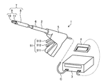
- FIG. 1 is a diagram schematically showing a treatment system according to Embodiment 1 of the present invention.
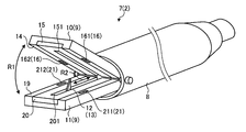
- FIG. 2 is a perspective view schematically showing the biological suturing device shown in FIG.
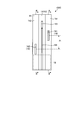
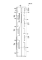
- FIG. 3 is a view of the first jaw shown in FIGS. 1 and 2 as viewed from the first clamping surface side.
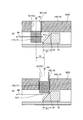
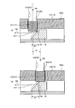
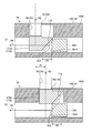
- FIG. 4 is a cross-sectional view of the first jaw shown in FIGS. 1 to 3.
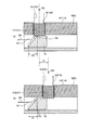
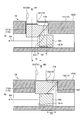
- FIG. 5 is a diagram illustrating a state in which the first and second staple holding members are interlocked with the operation of the driving member illustrated in FIG. 4.
- FIG. 6 is a diagram illustrating a state in which the first and second staple holding members are interlocked with the operation of the driving member illustrated in FIG. 4.
- FIG. 5 is a diagram illustrating a state in which the first and second staple holding members are interlocked with the operation of the driving member illustrated in FIG. 4.
- FIG. 7 is a diagram illustrating a state in which the first and second staple holding members are interlocked with the operation of the driving member illustrated in FIG. 4.
- FIG. 8 is a diagram illustrating a state in which the first and second staple holding members are interlocked with the operation of the driving member illustrated in FIG. 4.
- FIG. 9 is a view of the second jaw shown in FIGS. 1 and 2 as viewed from the second clamping surface side.
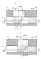
- FIG. 10 is a diagram schematically showing a first jaw constituting the living body suturing device according to Embodiment 2 of the present invention.
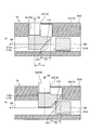
- FIG. 11 is a diagram illustrating a state in which the first and second staple holding members are interlocked with the operation of the driving member illustrated in FIG. 10.
- FIG. 12 is a diagram illustrating a state in which the first and second staple holding members are interlocked with the operation of the driving member illustrated in FIG. 10.
- FIG. 13 is a diagram illustrating a state in which the first and second staple holding members are interlocked with the operation of the driving member illustrated in FIG. 10.
- FIG. 14 is a diagram illustrating a state in which the first and second staple holding members are interlocked with the operation of the driving member illustrated in FIG. 10.
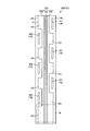
- FIG. 15 is a view of the first jaw constituting the living body suturing device according to Embodiment 3 of the present invention as viewed from the first clamping surface side.
- FIG. 16 is a view of the first jaw constituting the living body suturing device according to the fourth embodiment of the present invention as viewed from the first clamping surface side.
- FIG. 17 is a view of the first jaw constituting the living body suturing device according to the fifth embodiment of the present invention as seen from the first clamping surface side.
- FIG. 18 is a diagram showing a modification of the
- FIG. 1 is a diagram schematically showing a treatment system 1 according to Embodiment 1 of the present invention.
- the treatment system 1 treats (joins (or anastomoses), detaches, etc.) biological tissues to be treated by applying energy and stapling.
- the treatment system 1 includes a treatment tool 2, a control device 3, and a foot switch 4.
- the treatment tool 2 is, for example, a linear type surgical treatment tool for performing treatment on a living tissue through the abdominal wall.
- the treatment tool 2 includes a handle 5, a first shaft 6, and a living body suturing device 7.
- the handle 5 is a portion that the operator holds.
- the handle 5 is provided with a plurality of operation knobs 51 (in the first embodiment, three of first to third operation knobs 511 to 513).
- the first shaft 6 has a substantially cylindrical shape, and one end (the right end portion in FIG. 1) is connected to the handle 5.
- an electric cable C (FIG. 1) connected to the control device 3 is disposed from one end side to the other end side via the handle 5.
- FIG. 2 is a perspective view schematically showing the living body suturing device 7.
- the living body suturing device 7 is a disposable part discarded after use, and is detachably attached to the other end (the left end in FIG. 1) of the first shaft 6.
- the living body suturing device 7 is not limited to a configuration (disposable configuration) that is detachable from the first shaft 6, and may be configured integrally with the first shaft 6.
- the biological suturing device 7 includes a second shaft 8 and a clamping portion 9 as shown in FIG. 1 or FIG.
- the second shaft 8 has a substantially cylindrical shape, and one end (the right end portion in FIGS. 1 and 2) is the other end of the first shaft 6 (the left end portion in FIG. 1). ) Is detachable. Moreover, the clamping part 9 is attached to the other end (the left end part in FIGS. 1 and 2) of the second shaft 8.
- the first and second shafts 6 and 8 are connected to each other in a state where the second shaft 8 is attached to the first shaft 6, and according to the operation of the first operation knob 511 by the operator, First and second opening / closing mechanisms (not shown) for opening and closing the first and second jaws 10 and 11 (FIGS. 1 and 2) constituting the holding portion 9 are provided.
- first and second shafts 6 and 8 are connected to each other with the second shaft 8 attached to the first shaft 6, and according to the operation of the second operation knob 512 by the operator,
- the drive member 18 (see FIGS. 3 and 4) is operated to fire U-shaped first and second staples St1 and St2 (see FIG. 4) made of metal or resin to stapling the living tissue.
- First and second firing mechanisms (not shown) are provided.
- the first and second shafts 6 and 8 are connected to each other with the second shaft 8 attached to the first shaft 6, and according to the operation of the third operation knob 513 by the operator,
- First and second moving mechanisms (not shown) for moving the cutter 12 (FIG. 2) are provided.
- the electric cable C routed to the other end (the left end portion in FIG. 1) of the first shaft 6 with the second shaft 8 attached to the first shaft 6. Are connected to the first and second energy generators 15 and 20 (FIG. 2).
- the clamping unit 9 is a part that clamps a living tissue and treats the living tissue.
- the clamping unit 9 includes a first jaw 10, a second jaw 11, and a cutter 12 (FIG. 2).
- the first and second jaws 10 and 11 are pivotally supported on the other end (left end portion in FIGS. 1 and 2) of the second shaft 8 so as to be opened and closed in the direction of the arrow R1 (FIG. 2).
- the living tissue can be clamped according to the operation of the operation knob 511.
- the detailed configuration of the first and second jaws 10 and 11 will be described later.
- the cutter 12 is attached to the other end of the second shaft 8 so as to be movable along the direction of the arrow R2 (FIG.
- the cutter 12 has a function as the excision part 13 according to the present invention.
- the first jaw 10 is disposed on the upper side in FIGS. 1 and 2 with respect to the second jaw 11, and has a hollow, substantially rectangular parallelepiped shape extending along the central axis of the second shaft 8.
- the material of the first jaw 10 include a material having high heat resistance and excellent electrical insulation, for example, PEEK (polyether ether ketone) resin.
- the shape of the first jaw 10 is not limited to a rectangular parallelepiped shape, and it may be configured to improve the insertability to the trocar by giving the outer peripheral surface a curvature. 1 and 2 of the first jaw 10 functions as a first clamping surface 14 that clamps the living tissue with the second jaw 11.
- FIG. 3 is a view of the first jaw 10 as viewed from the first clamping surface 14 side.
- FIG. 4 is a cross-sectional view of the first jaw 10. Specifically, FIG. 4A is a cross-sectional view taken along line AA in FIG.
- FIG. 4B is a sectional view taken along line BB in FIG.
- the first energy generating unit 15 is embedded in the first clamping surface 14 at a substantially central position in the width direction of the first clamping surface 14.
- the first energy generation unit 15 is embedded in the first clamping surface 14 with the surface exposed, and generates energy under the control of the control device 3.
- the 1st energy generation part 15 also has a function as the cutting part 13 (energy generation part) which concerns on this invention.
- the first energy generating unit 15 is configured by, for example, a conductive material such as copper, or a heater that generates heat when electric power is applied.
- the first energy generation unit 15 extends along the longitudinal direction of the first jaw 10 and is set so that the longitudinal dimension thereof is substantially the same as the longitudinal dimension of the first jaw 10.
- the first energy generation unit 15 has a surface (a surface on the lower side in FIG. 2) in a region other than the region where the first energy generation unit 15 is disposed on the first clamping surface 14 (first described later). , Except for the second staple ejection holes 161 and 162), it is embedded in the first clamping surface 14 so as to be substantially flush.
- the first energy generating unit 15 is connected to the second jaw 11 by the control device 3 via the electric cable C and the connection unit (not shown) with the second shaft 8 attached to the first shaft 6. Energy is generated by supplying electric power to the second energy generation unit 20 (FIG. 2). That is, the first energy generating unit 15 is configured as an electrode or a heater to which high frequency power is supplied.
- one end in the longitudinal direction of the first energy generation unit 15 (as shown in FIG. 2 or 3) is provided at a substantially central position in the width direction of the first energy generation unit 15.
- a first cutter moving groove that extends along the longitudinal direction from the end portion on the second shaft 8 side (in FIG. 2, right end portion (lower end portion in FIG. 3)) toward the other end and serves as a moving path of the cutter 12. 151 is formed.
- first and second staple ejection holes 161 and 162 for ejecting the first and second staples St ⁇ b> 1 and St ⁇ b> 2 are formed in the first clamping surface 14.
- the first and second staple ejection holes 161 and 162 differ only in the positions formed in the first jaw 10 and have the same shape and function. For this reason, the description of the first and second staple ejection holes 161 and 162 will be described by using the first and second staple ejection holes 161 and 162 as the staple ejection holes 16 (FIGS. 2 to 4).
- the first and second staples St1, St2 are different only in the positions where they are disposed, and have the same shape and function.
- the first and second staples St1 and St2 will be described as the staple St (FIG. 4).
- the staple ejection hole 16 is formed by an elongated hole that penetrates the inside and outside of the first jaw 10 and extends along the longitudinal direction of the first jaw 10, and holds the staple St on the first clamping surface. 14 in the normal direction R3 (FIG. 4).
- the normal direction R3 corresponds to the first direction according to the present invention.
- the normal direction R3 is referred to as a first direction R3.
- the formation positions of the first and second staple ejection holes 161 and 162 will be described later.
- first and second staple holding members 171 and 172 and a drive member 18 are disposed inside the first jaw 10.
- the first and second staple holding members 171 and 172 differ only in the positions where they are disposed on the first jaw 10, and have the same shape and function. For this reason, the first and second staple holding members 171 and 172 will be described as the staple holding member 17 with respect to overlapping portions.
- the staple holding member 17 has a rectangular parallelepiped shape that can be inserted into the staple ejection hole 16, and holds the staple St on the upper surface in FIG.
- the staple holding member 17 is disposed so as to be movable from the inside of the first jaw 10 to the staple ejection hole 16 in the first direction R3.
- the drive member 18 is disposed inside the first jaw 10, and in the longitudinal direction of the first jaw 10 by the first and second firing mechanisms (not shown) according to the operation of the second operation knob 512 by the operator. Move to R4 (FIGS. 3 and 4). Then, the drive member 18 presses the staple holding member 17 at the distal end portion (the end portion on the distal end side of the first jaw 10) in accordance with the movement of the first jaw 10 toward the distal end side along the longitudinal direction R4. Then, the staple holding member 17 is moved in the first direction R3 (the staple St is ejected from the staple ejection hole 16).
- the longitudinal direction R4 intersects with the first direction R3 (orthogonal in the first embodiment) and corresponds to the second direction according to the present invention.
- the longitudinal direction R4 is referred to as a second direction R4.
- the drive member 18 is formed in a prismatic shape, and the distal end portion of the drive member 18 is inclined toward the base end side (the base end side of the first jaw 10) from the bottom to the top in FIG.
- a drive-side inclined surface 181 is formed.
- the drive-side inclined surface 181 has a drive-side slidable contact area Ar1 that slidably contacts the staple holding member 17 when the drive member 18 moves to the distal end side of the first jaw 10 along the second direction R4 (FIG. 3, FIG. 3). 4).
- the drive-side inclined surface 181 is a portion that moves the staple holding member 17 in the first direction R3 while being in sliding contact with the staple holding member 17.
- the first and second staple ejection holes 161 and 162 are formed at the following positions, respectively.
- the first staple injection hole 161 is formed when the first clamping surface 14 is divided into one (the right side in FIG. 3) surface 141 and the other (the left side in FIG. 3) surface 142 with the cut portion 13 as the center.
- the surface 141 is provided.
- the second staple ejection hole 162 is provided on the other surface 142.
- the first and second staple ejection holes 161 and 162 are provided at positions shifted from each other in the second direction R4, as shown in FIG. 3 or FIG.
- the first staple ejection hole 161 is provided at a position shifted from the position facing the second staple ejection hole 162 to the distal end side of the first jaw 10 along the second direction R4 with respect to the cut portion 13 as a reference.
- the distance between the first and second staple ejection holes 161 and 162 shifted in the second direction R4 is Pi (FIGS. 3 and 4).
- a length dimension along the second direction R4 in the driving side sliding contact area Ar1 is defined as D1 (FIG. 4).
- the first staple St1 and the first staple holding member 171 are respectively disposed at positions corresponding to the first staple ejection holes 161 as shown in FIG.
- the second staple St2 and the second staple holding member 172 are disposed at positions corresponding to the second staple ejection holes 162, respectively.
- FIG. 5A, FIG. 6A, FIG. 7A, and FIG. 8A are cross-sectional views corresponding to FIG. 5 (b), FIG. 6 (b), FIG. 7 (b), and FIG. 8 (b) are cross-sectional views corresponding to FIG. 4 (b).
- the second staple ejection hole 162 (second staple St2 and second staple holding member 172) is located with respect to the first staple ejection hole 161 (first staple St1 and first staple holding member 171).
- the first jaw 10 is provided at a position shifted to the proximal end side. Therefore, the driving member 18 first comes into contact with the second staple holding member 172 in accordance with the movement of the first jaw 10 toward the distal end side along the second direction R4.
- the driving-side inclined surface 181 is slidably contacted with the second staple holding member 172 as shown in FIGS. 5B and 6B. 2
- the staple holding member 172 is pressed.
- FIG. 6 shows a point in time when the ejection of the second staple St2 is completed.
- FIG. 6B shows the second staple St2.
- FIG. 7B and FIG. 8B the second staple St2 is shown for convenience of explanation.
- One staple holding member 171 is pressed. As a result, the first staple holding member 171 moves in the first direction R3 and is inserted from the inside of the first jaw 10 into the first staple ejection hole 161. Then, the first staple St1 is ejected from the first staple ejection hole 161 in the first direction R3.
- the second jaw 11 has a substantially rectangular parallelepiped shape extending along the central axis of the second shaft 8.
- a material having high heat resistance and excellent electrical insulation for example, PEEK resin can be exemplified.
- the shape of the second jaw 11 is not limited to a rectangular parallelepiped shape like the first jaw 11, but is configured to improve the insertability to the trocar by giving the outer peripheral surface a curvature. It doesn't matter.
- the upper surface of the second jaw 11 in FIGS. 1 and 2 functions as a second clamping surface 19 that clamps the living tissue with the first clamping surface 14.
- FIG. 9 is a view of the second jaw 11 as viewed from the second clamping surface 19 side.
- the second energy generating unit 20 is embedded in the second clamping surface 19 at a substantially central position in the width direction of the second clamping surface 19.
- the second energy generation unit 20 is embedded in the second clamping surface 19 with the surface exposed, and generates energy under the control of the control device 3.
- the 2nd energy generation part 20 also has a function as the cutting part 13 (energy generation part) which concerns on this invention.
- the 2nd energy generation part 20 is comprised by the heater which heat
- the second energy generating unit 20 is set so as to extend along the longitudinal direction of the second jaw 11 and the longitudinal dimension thereof is substantially the same as the longitudinal dimension of the second jaw 11.
- the second energy generation unit 20 has a surface (upper surface in FIG. 2) in a region other than a region where the second energy generation unit 20 is disposed on the second clamping surface 19 (first described later). Embedded in the second clamping surface 19 so as to be substantially flush with the second needle tip receiving portions 211 and 212). Furthermore, the second energy generation unit 20 faces the first energy generation unit 15 in a state where the first and second jaws 10 and 11 are closed.
- the second energy generation unit 20 generates the first energy by the control device 3 via the electric cable C and the connection unit (not shown) with the second shaft 8 attached to the first shaft 6. Energy is generated by supplying electric power to the unit 15. That is, the second energy generation unit 15 is configured as an electrode or a heater to which high frequency power is supplied.
- a substantially central position in the width direction of the second energy generating unit 20 (a position facing the first cutter moving groove 151 in a state where the first and second jaws 10 and 11 are closed).
- a second cutter moving groove 201 that extends along the longitudinal direction toward the other end and serves as a moving path of the cutter 12 is formed.
- first and second needle tip receiving portions 211 and 212 are formed on the second clamping surface 19 in regions other than the second energy generating portion 20, respectively.
- the first and second needle tip receiving portions 211 and 212 are different only in the formed positions, and have the same shape and function. For this reason, with respect to the portions where the descriptions of the first and second needle tip receiving portions 211 and 212 overlap, the first and second needle tip receiving portions 211 and 212 are used as the needle tip receiving portion 21 (FIGS. 2 and 9). explain.
- the needle tip receiving portion 21 is constituted by a recess formed in the second clamping surface 19.
- the needle tip receiving portion 21 receives the needle tips (both ends of the U-shaped staple St) ejected from the staple ejection hole 16 and deforms the needle tips (the U-shaped staple St is substantially B). It has a function of deforming into a letter shape.
- the first needle tip receiving portion 211 has the second clamping surface 19 on one side (left side in FIG. 9) and the other side (right side in FIG. 9) with the second clamping surface 19 centered on the cutting portion 13 (second energy generating portion 20). ) Is provided on one surface 191.
- the one surface 191 faces one surface 141 of the first clamping surface 14 in a state where the first and second jaws 10 and 11 are closed.
- the first needle tip receiving portion 211 faces the first staple ejection hole 161 in a state where the first and second jaws 10 and 11 are closed.
- the second needle tip receiving portion 212 is provided on the other surface 192.
- the other surface 192 faces the other surface 142 of the first clamping surface 14 in a state where the first and second jaws 10 and 11 are closed.
- the second needle tip receiving portion 212 faces the second staple ejection hole 162 in a state where the first and second jaws 10 and 11 are closed.
- the needle tip receiving portion 21 is configured to receive the staple tips of the staple St (both ends of the U-shaped staple St). Therefore, it may be provided in one-to-two.
- the foot switch 4 is a part operated by the operator with his / her foot. Then, in response to the operation to the foot switch 4, for example, supply of high-frequency power or the like is started from the control device 3 to the biological suturing device 7 (first and second energy generating units 15 and 20).
- the first and second energy generators 15 and 20 are configured as electrodes or heaters. In the following, for convenience of explanation, the case where the first and second energy generating units 15 and 20 are configured by electrodes (when high-frequency power is supplied between the first and second energy generating units 15 and 20). Explained as an example.
- the means for starting the supply of high-frequency power is not limited to the foot switch 4, and a switch operated by hand or the like may also be employed.
- the control device 3 includes a CPU (Central Processing Unit) and the like, and comprehensively controls the operation of the biological suturing device 7 according to a predetermined control program. More specifically, the control device 3 responds to the operation of the foot switch 4 by the surgeon via the electric cable C and the connecting portion (not shown), and the first and second energy generating portions 15 and 20. During this period, high-frequency power having a preset output is supplied.
- CPU Central Processing Unit
- a high-frequency current flows between the first and second energy generation units 15 and 20, and a part of the living tissue sandwiched between the first and second energy generation units 15 and 20 (hereinafter, Joule heat is generated at the energy bonding site. And the energy joining part is joined by generation
- the surgeon operates the third operation knob 513.
- the cutter 12 moves to the distal end side of the living body suturing device 7, and cuts out the substantially center position in the width direction at the energy bonding portion.
- the stapling of the living tissue by operating the second operation knob 512 is performed between the time when the living tissue is held by the first and second jaws 10 and 11 until the foot switch 4 is operated, or the foot Between the time when the switch 4 is operated and the time when the third operation knob 513 is operated (while supplying high-frequency power to the first and second energy generating units 15 and 20 or after completing the supply of the high-frequency power) It may be executed at any timing.
- a notification unit not shown
- the surgeon recognizes that the above-described high-frequency power supply has been completed.
- the notification unit include a display that displays predetermined information, an LED (Light Emitting Diode) that notifies predetermined information by lighting or blinking, and a speaker that notifies predetermined information by sound.
- the first and second staple ejection holes 161 and 162 are provided at positions shifted from each other in the second direction R4. Therefore, the driving member 18 first presses the second staple holding member 172 and then presses the first staple holding member 171 in accordance with the movement of the first jaw 10 toward the distal end side along the second direction R4. . That is, the drive member 18 does not press the first and second staple holding members 171 and 172 at the same time when the staple St is started to be driven. From the above, the surgeon only moves the drive member 18 along the second direction R4 along the second direction R4 by operating the second operation knob 512 with a relatively small force at the start of driving of the staple St. The staple St can be driven into the living tissue. Therefore, the operability of the treatment tool 2 can be improved.
- a period that partially overlaps the first period and the second period it is necessary to simultaneously press the first and second staple holding members 171 and 172 with the driving member 18 during the overlapping period. is there. For this reason, the surgeon needs to operate the second operation knob 512 with a relatively large force during the overlapping period.
- the first and second periods do not overlap each other and are independent periods, so that the surgeon can always perform the first and second periods with a relatively small force during the first and second periods.
- the two operation knob 512 may be operated. Therefore, the operability of the treatment tool 2 can be further improved.
- FIG. 10 is a diagram schematically showing a living body suturing device 7A according to Embodiment 2 of the present invention. Specifically, FIG. 10A is a cross-sectional view corresponding to FIG. FIG. 10B is a cross-sectional view corresponding to FIG.
- the staple holding member 17 and the drive member 18 have shapes different from those of the biological suturing device 7 described in the first embodiment. Different staple holding members 17A and drive members 18A are employed.
- the drive member 18 ⁇ / b> A has the drive-side inclined surface 181 at the tip portion omitted from the drive member 18 described in the first embodiment.
- tip of the drive member 18A is comprised by the flat surface 181A orthogonal to 2nd direction R4.
- the staple holding member 17A corresponds to the first and second staple ejection holes 161 and 162 (first and second staples St1 and St2) similarly to the staple holding member 17 described in the first embodiment.
- 1 and 2nd staple holding members 171A and 172A are provided.
- the first and second staple holding members 171A and 172A have the same shape and function. For this reason, as for the overlapping description of the first and second staple holding members 171A and 172A, the first and second staple holding members 171A and 172A will be described as the staple holding member 17A.
- the staple holding member 17A has the same function as the staple holding member 17 described in the first embodiment and is disposed at the same position, but has a different shape. Specifically, as shown in FIG.
- the staple holding member 17 ⁇ / b> A is formed in a prismatic shape extending in the width direction of the first jaw 10. Then, on the proximal end side of the staple holding member 17 (the proximal end side of the first jaw 10), a holding-side inclined surface 173 that is inclined toward the proximal end side is formed from the lower side to the upper side in FIG. ing.
- the holding-side inclined surface 173 has a holding-side slidable contact area Ar2 (see FIG. 10) that slidably contacts the front end of the drive member 18A when the drive member 18A moves to the front end side of the first jaw 10 along the second direction R4. ). That is, the holding-side inclined surface 173 is a portion that is pressed by the driving member 18A while being in sliding contact with the driving member 18A.
- 11 to 14 are views showing a state in which the first and second staple holding members 171A and 172A are interlocked with the operation of the driving member 18A. Specifically, (a) in FIG. 11, (a) in FIG. 12, (a) in FIG. 13, and (a) in FIG. 14 are cross-sectional views corresponding to (a) in FIG. 11B, FIG. 12B, and FIG.
- FIGS. 14B are cross-sectional views corresponding to FIG. 10B.
- the behavior of the first and second staple holding members 171A and 172A according to the movement of the driving member 18A toward the distal end side of the first jaw 10 is shown in time series in the order of FIGS.
- the drive member 18A moves from the pre-operation position (position shown in FIG. 10) on the proximal end side of the first jaw 10 to the first and second firing mechanisms (illustrated). Omitted) moves to the tip side of the first jaw 10 along the second direction R4.
- the second staple ejection hole 162 (second staple St2 and second staple holding member 172A) is similar to the first embodiment described above in that the first staple ejection hole 161 (first staple St1 and first staple holding).
- the member 171 ⁇ / b> A) is provided at a position shifted toward the proximal end side of the first jaw 10.
- the drive member 18A first contacts the second staple holding member 172A in accordance with the movement of the first jaw 10 toward the distal end side along the second direction R4.
- the holding-side inclined surface 173 of the second staple holding member 172A is moved toward the tip of the driving member 18A as shown in FIGS. 11B and 12B. It is pressed while sliding.
- the second staple holding member 172A moves in the first direction R3 and moves from the inside of the first jaw 10 to the second staple ejection hole 162.
- the second staple St2 is ejected from the second staple ejection hole 162 in the first direction R3.
- FIG. 12 shows a point in time when the ejection of the second staple St2 is completed, but for convenience of explanation, the second staple St is shown in FIG.
- the second staple St2 is shown for convenience of explanation.
- the holding-side inclined surface 173 of the first staple holding member 171A moves to the tip of the driving member 18A as shown in FIGS. 13 (a) and 14 (a). It is pressed while sliding.
- the first staple holding member 171A moves in the first direction R3 and moves from the inside of the first jaw 10 to the first staple ejection hole 161. Then, the first staple St1 is ejected from the first staple ejection hole 161 in the first direction R3.
- the staple holding member 17A and the driving member 18A having different shapes from the staple holding member 17 and the driving member 18 described in the first embodiment are employed. Also, the same effects as those of the first embodiment described above can be obtained.
- FIG. 15 is a view of the first jaw 10B constituting the living body suturing device 7B according to Embodiment 3 of the present invention as viewed from the first clamping surface 14 side.
- the first and second staple ejection holes 161 and 162 are respectively provided to the biological suturing device 7 described in the first embodiment.
- a plurality (three in the third embodiment) are provided.
- the three first staple ejection holes 161 are juxtaposed along the second direction R4 on one surface 141.
- three first staples St1 and first staple holding members 161 are provided in correspondence with the three first staple ejection holes 161.
- the three second staple ejection holes 162 are arranged side by side along the second direction R4 on the other surface 142.
- three second staples St ⁇ b> 2 and second staple holding members 162 are provided in correspondence with the three second staple ejection holes 162.
- the second jaw according to the third embodiment is provided with three first needle tip receiving portions corresponding to the three first staple ejection holes 161, and three Three second needle tip receiving portions are provided corresponding to the second staple ejection holes 162.
- first and second staple ejection holes 161 and 162 are provided as in the third embodiment described above, the same effects as those of the first embodiment described above can be obtained. Further, since a plurality of first and second staple ejection holes 161 and 162 are provided, the bonding strength of the living tissue can be further reinforced by stapling with the plurality of first and second staples St1 and St2. In particular, the intervals Pi1 and Pi2 are set to twice D1 (twice Pi). Therefore, while improving the operability of the treatment instrument 2, the first and second staples St1 and St2 can be densely driven into the living tissue to reinforce the bonding strength of the living tissue.
- FIG. 16 is a view of the first jaw 10B constituting the living body suturing device 7C according to the fourth embodiment of the present invention as viewed from the first clamping surface 14 side.
- the first energy generating unit 15 is different in shape from the first energy generating unit 15 as compared with the biological suturing device 7B described in the third embodiment.
- An energy generating unit 15C is employed.
- the first energy generating unit 15C includes a main energy generating unit 152 and a sub energy generating unit 153 as shown in FIG.
- the first energy generation unit 15C is arranged with the first energy generation unit 15C on the first clamping surface 14 in the same manner as the first energy generation unit 15 described in the first to third embodiments. It is embedded in the first clamping surface 14 so as to be substantially flush with a region other than the region that is formed.
- the main energy generation unit 152 is provided between the three first staple ejection holes 161 and the three second staple ejection holes 162, and the first energy generation unit 15 described in the first to third embodiments described above. Have the same shape.
- the sub energy generating portion 153 is a portion that is integrally formed with the main energy generating portion 152 and that protrudes from the outer edge in the width direction of the main energy generating portion 152 in a direction away from the first and second staple ejection holes 161 and 162. . That is, the auxiliary energy generation unit 153 is positioned between each adjacent first staple ejection hole 161 and between each adjacent second staple ejection hole 162.
- the second energy generation unit provided in the second jaw according to the fourth embodiment has a shape corresponding to the first energy generation unit 15C.
- a sub-energy generating unit 153 is provided between each adjacent first staple ejection hole 161 and between each adjacent second staple ejection hole 162. For this reason, in the living tissue, energy can be applied between the adjacent first staples St1 and between the adjacent second staples St2, and the bonding strength of the living tissue can be further increased.
- FIG. 17 is a view of the first jaw 10B constituting the living body suturing device 7D according to Embodiment 5 of the present invention as viewed from the first clamping surface 14 side.
- the living body suturing device 7D according to the fifth embodiment employs a configuration in which the cutter 12 is omitted and the living tissue is excised by applying energy. That is, in the biological suturing device 7D, as shown in FIG. 17, the first energy generating unit 15D having a shape different from that of the first energy generating unit 15 is different from the biological suturing device 7C described in the fourth embodiment. Adopted.
- the first energy generation unit 15D includes a cutting energy generation unit 154 and a joining energy generation unit 155, as shown in FIG.
- the excision energy generation unit 154 is a part that applies energy to the living tissue and excises the living tissue.
- the cutting energy generating part 154 extends along the longitudinal direction of the first jaw 10B, and is set so that the longitudinal dimension is substantially the same as the longitudinal dimension of the first jaw 10B.
- the resecting energy generation unit 154 is disposed at a substantially central position in the width direction of the first jaw 10B.
- the excision energy generating unit 154 is disposed in the same manner as the first energy generating unit 15 described in the first to third embodiments. It is embedded in the first clamping surface 14 so as to be substantially flush with a region other than the region that is formed.
- the joining energy generating unit 155 is a part that applies energy to the living tissue and joins the living tissue.
- the joining energy generation unit 155 is configured by dividing the first energy generation unit 15C described in the fourth embodiment into two bodies at the center in the width direction.
- the joining energy generating sections 155 are cut so that the sub energy generating sections 153 are positioned between the adjacent first staple ejection holes 161 and between the adjacent second staple ejection holes 162.
- a predetermined gap is provided from the energy generating unit 154 and the cutting energy generating unit 154 is disposed on both sides in the width direction.
- Each joining energy generating portion 155 is embedded in the first clamping surface 14 so that the surface thereof is substantially flush with the surface of the cutting energy generating portion 154.
- the second energy generation unit provided in the second jaw according to the fifth embodiment has a shape corresponding to the first energy generation unit 15D.
- the control device 3 according to the fifth embodiment outputs a preset output between each bonding energy generation unit 155 in the first energy generation unit 15D and each bonding energy generation unit in the second energy generation unit.
- a high-frequency power of an output similar to the output described in Embodiments 1 to 4 (hereinafter referred to as a first output) is supplied.
- a first output A high-frequency power of an output similar to the output described in Embodiments 1 to 4
- control device 3 generates high-frequency power having a second output higher than the first output between the ablation energy generation unit 154 in the first energy generation unit 15D and the ablation energy generation unit in the second energy generation unit. Supply. Thereby, the living tissue sandwiched between the excision energy generation unit 154 in the first energy generation unit 15D and the excision energy generation unit in the second energy generation unit is excised.
- FIG. 18 is a diagram showing a modification of the fifth embodiment of the present invention. Specifically, FIG. 18 corresponds to FIG. In the above-described first jaw 10B according to the fifth embodiment, as shown in FIG. 18, a configuration in which the sub energy generation units 153 are omitted from the two joining energy generation units 155 may be employed. Even in the case of such a configuration, similarly to the above-described fifth embodiment, by omitting the cutter 12, it is possible to reduce the number of parts and reduce the size of the biological suturing device 7D.
- the surfaces of the first energy generating unit 15D are configured as flat surfaces, but are not limited thereto.
- the shape of the surface may be changed to a surface other than a flat surface.
- the cutter 12 is omitted, the surface of the first energy generation unit 15 or 15C is changed to a surface other than a flat surface, and the living tissue is excised by applying energy. You may comprise.
- the configuration according to the above-described second embodiment may be employed in the biological suturing devices 7B to 7D according to the above-described third to fifth embodiments.
Landscapes
- Health & Medical Sciences (AREA)
- Life Sciences & Earth Sciences (AREA)
- Surgery (AREA)
- Heart & Thoracic Surgery (AREA)
- Engineering & Computer Science (AREA)
- Biomedical Technology (AREA)
- Nuclear Medicine, Radiotherapy & Molecular Imaging (AREA)
- Medical Informatics (AREA)
- Molecular Biology (AREA)
- Animal Behavior & Ethology (AREA)
- General Health & Medical Sciences (AREA)
- Public Health (AREA)
- Veterinary Medicine (AREA)
- Surgical Instruments (AREA)
Abstract
生体縫合装置7は、ステープル射出孔16が設けられた第1挟持面14を有する第1ジョー10と、ステープル射出孔16から射出されるステープルと、ステープルを保持するステープル保持部材と、第2方向R4に移動し、当該移動に応じてステープル保持部材を押圧してステープルをステープル射出孔16から射出させる駆動部材と、第2方向R4に沿って配置され、第1ジョー10及び第2ジョーにて挟持された生体組織を切除する切除部13とを備える。ステープル射出孔16は、切除部13を中心にして第1挟持面14を一方の面141と他方の面142とに分割した場合に、一方の面に設けられた第1ステープル射出孔161と、他方の面142に設けられた第2ステープル射出孔162とを備える。第1,第2ステープル射出孔161,162は、第2方向R4に互いにずれた位置にそれぞれ設けられている。
Description
本発明は、生体縫合装置に関する。
従来、エネルギの付与により生体組織を接合し、ステープリングにより当該接合強度を補強する生体縫合装置が知られている(例えば、特許文献1参照)。
特許文献1に記載の生体縫合装置(電気手術具)は、第1挟持面を有する長尺状の第1ジョー(顎部材)と、第1挟持面に対向して当該第1挟持面との間で生体組織を挟持する第2挟持面を有する長尺状の第2ジョー(顎部材)とを備える。そして、第1ジョーには、生体組織にステープルを打ち込む構造が設けられている。また、第2ジョーには、生体組織にエネルギを付与する一対の電極が設けられている。
特許文献1に記載の生体縫合装置(電気手術具)は、第1挟持面を有する長尺状の第1ジョー(顎部材)と、第1挟持面に対向して当該第1挟持面との間で生体組織を挟持する第2挟持面を有する長尺状の第2ジョー(顎部材)とを備える。そして、第1ジョーには、生体組織にステープルを打ち込む構造が設けられている。また、第2ジョーには、生体組織にエネルギを付与する一対の電極が設けられている。
具体的に、特許文献1に記載の生体縫合装置では、生体組織にステープルを打ち込む構造として、以下の構造を採用している。
第1挟持面には、ステープルを外部に射出する複数の第1,第2ステープル射出孔が形成されている。複数の第1ステープル射出孔は、第1挟持面の幅方向の一端側に位置し、当該第1挟持面の長手方向に沿って並設されている。また、複数の第2ステープル射出孔は、第1挟持面の幅方向の他端側に位置し、各第1ステープル射出孔に対して当該幅方向にそれぞれ対向する位置に設けられている。
また、第1ジョーの内部には、複数の第1ステープル保持部材(ドライバ)と、複数の第2ステープル保持部材(ドライバ)と、駆動部材(ウェッジ)とが設けられている。
複数の第1ステープル保持部材は、複数の第1ステープル射出孔に対してそれぞれ設けられ、第1ジョーの内部において、各ステープルをそれぞれ保持する。
複数の第2ステープル保持部材は、第1ステープル保持部材と同一の形状を有し、複数の第2ステープル射出孔に対してそれぞれ設けられ、第1ジョーの内部において、各ステープルをそれぞれ保持する。
駆動部材は、生体縫合装置に設けられた操作ノブへの操作に応じて、第1ジョーの内部において、当該第1ジョーの長手方向に沿って先端側に移動する。そして、駆動部材は、当該移動に応じて各第1,第2ステープル保持部材を順次、押圧し、ステープルを複数の第1,第2ステープル射出孔から順次、射出させる。
第1挟持面には、ステープルを外部に射出する複数の第1,第2ステープル射出孔が形成されている。複数の第1ステープル射出孔は、第1挟持面の幅方向の一端側に位置し、当該第1挟持面の長手方向に沿って並設されている。また、複数の第2ステープル射出孔は、第1挟持面の幅方向の他端側に位置し、各第1ステープル射出孔に対して当該幅方向にそれぞれ対向する位置に設けられている。
また、第1ジョーの内部には、複数の第1ステープル保持部材(ドライバ)と、複数の第2ステープル保持部材(ドライバ)と、駆動部材(ウェッジ)とが設けられている。
複数の第1ステープル保持部材は、複数の第1ステープル射出孔に対してそれぞれ設けられ、第1ジョーの内部において、各ステープルをそれぞれ保持する。
複数の第2ステープル保持部材は、第1ステープル保持部材と同一の形状を有し、複数の第2ステープル射出孔に対してそれぞれ設けられ、第1ジョーの内部において、各ステープルをそれぞれ保持する。
駆動部材は、生体縫合装置に設けられた操作ノブへの操作に応じて、第1ジョーの内部において、当該第1ジョーの長手方向に沿って先端側に移動する。そして、駆動部材は、当該移動に応じて各第1,第2ステープル保持部材を順次、押圧し、ステープルを複数の第1,第2ステープル射出孔から順次、射出させる。
ところで、第1ジョーから射出されたステープルは、先ず当該第1ジョーと第2ジョーとに挟持された生体組織を穿刺し、次に当該第2ジョーの第2挟持面に設けられたアンビルに針先が当接し、最後にアンビルにて針先が折り曲げられる。すなわち、生体組織にステープルを打ち込む際には、ステープルが上述した過程を辿るため、比較的に大きな駆動力(駆動部材を動作させる力)を駆動部材に与える必要がある。
ここで、特許文献1に記載の生体縫合装置では、第1,第2ステープル射出孔(第1,第2ステープル保持部材)は、第1ジョーの幅方向にそれぞれ対向する位置に設けられている。このため、駆動部材は、第1ジョーの長手方向に沿う先端側への移動に応じて、同時に2つの第1,第2ステープル保持部材を順次、押圧し、第1,第2ステープル射出孔から同時に2つのステープルを順次、射出させる。すなわち、ステープルを同時に2つずつ、生体組織に打ち込むことになるため、ステープルの打ち込み開始時に急激に大きな駆動力(駆動部材を動作させる力)を駆動部材に与える必要がある、という問題がある。
ここで、特許文献1に記載の生体縫合装置では、第1,第2ステープル射出孔(第1,第2ステープル保持部材)は、第1ジョーの幅方向にそれぞれ対向する位置に設けられている。このため、駆動部材は、第1ジョーの長手方向に沿う先端側への移動に応じて、同時に2つの第1,第2ステープル保持部材を順次、押圧し、第1,第2ステープル射出孔から同時に2つのステープルを順次、射出させる。すなわち、ステープルを同時に2つずつ、生体組織に打ち込むことになるため、ステープルの打ち込み開始時に急激に大きな駆動力(駆動部材を動作させる力)を駆動部材に与える必要がある、という問題がある。
本発明は、上記に鑑みてなされたものであって、ステープルの打ち込み開始時の駆動力を低減させることができる生体縫合装置を提供することを目的とする。
上述した課題を解決し、目的を達成するために、本発明に係る生体縫合装置は、ステープル射出孔が設けられた第1挟持面を有する第1ジョーと、前記第1挟持面に対向して当該第1挟持面との間で生体組織を挟持する第2挟持面を有する第2ジョーと、前記ステープル射出孔から射出されるステープルと、前記ステープルを保持するステープル保持部材と、前記ステープル射出孔から前記ステープルが射出される第1方向に交差する第2方向に移動し、当該移動に応じて前記ステープル保持部材を押圧して前記ステープルを前記ステープル射出孔から射出させる駆動部材と、前記第2方向に沿って配置され、前記第1挟持面及び前記第2挟持面にて挟持された前記生体組織を切除する切除部と、を備え、前記ステープル射出孔は、前記切除部を中心にして前記第1挟持面を一方の面と他方の面とに分割した場合に、当該一方の面に設けられた第1ステープル射出孔と、当該他方の面に設けられた第2ステープル射出孔と、を備え、前記第1ステープル射出孔と前記第2ステープル射出孔とは、前記第2方向に互いにずれた位置にそれぞれ設けられている。
本発明に係る生体縫合装置によれば、ステープルの打ち込み開始時の駆動力を低減させることができる、という効果を奏する。
以下に、図面を参照して、本発明を実施するための形態(以下、実施の形態)について説明する。なお、以下に説明する実施の形態によって本発明が限定されるものではない。さらに、図面の記載において、同一の部分には同一の符号を付している。
(実施の形態1)
〔処置システムの概略構成〕
図1は、本発明の実施の形態1に係る処置システム1を模式的に示す図である。
処置システム1は、エネルギの付与及びステープリングにより、処置対象である生体組織を処置(接合(若しくは吻合)及び切離等)する。この処置システム1は、図1に示すように、処置具2と、制御装置3と、フットスイッチ4とを備える。
〔処置システムの概略構成〕
図1は、本発明の実施の形態1に係る処置システム1を模式的に示す図である。
処置システム1は、エネルギの付与及びステープリングにより、処置対象である生体組織を処置(接合(若しくは吻合)及び切離等)する。この処置システム1は、図1に示すように、処置具2と、制御装置3と、フットスイッチ4とを備える。
〔処置具の構成〕
処置具2は、例えば、腹壁を通して生体組織に処置を行うためのリニアタイプの外科医療用処置具である。この処置具2は、図1に示すように、ハンドル5と、第1シャフト6と、生体縫合装置7とを備える。
ハンドル5は、術者が把持する部分である。そして、このハンドル5には、図1に示すように、複数の操作ノブ51(本実施の形態1では、第1~第3操作ノブ511~513の3つ)が設けられている。
第1シャフト6は、図1に示すように、略円筒形状を有し、一端(図1中、右端部)がハンドル5に接続されている。この第1シャフト6の内部には、制御装置3に接続された電気ケーブルC(図1)がハンドル5を介して一端側から他端側まで配設されている。
処置具2は、例えば、腹壁を通して生体組織に処置を行うためのリニアタイプの外科医療用処置具である。この処置具2は、図1に示すように、ハンドル5と、第1シャフト6と、生体縫合装置7とを備える。
ハンドル5は、術者が把持する部分である。そして、このハンドル5には、図1に示すように、複数の操作ノブ51(本実施の形態1では、第1~第3操作ノブ511~513の3つ)が設けられている。
第1シャフト6は、図1に示すように、略円筒形状を有し、一端(図1中、右端部)がハンドル5に接続されている。この第1シャフト6の内部には、制御装置3に接続された電気ケーブルC(図1)がハンドル5を介して一端側から他端側まで配設されている。
〔生体縫合装置の構成〕
図2は、生体縫合装置7を模式的に示す斜視図である。
生体縫合装置7は、使用後に廃棄されるディスポーザブルな部分であり、第1シャフト6の他端(図1中、左端部)に着脱自在に取り付けられる。なお、生体縫合装置7は、第1シャフト6に対して着脱自在とする構成(ディスポーザブルな構成)に限らず、第1シャフト6に一体的に構成しても構わない。この生体縫合装置7は、図1または図2に示すように、第2シャフト8と、挟持部9とを備える。
図2は、生体縫合装置7を模式的に示す斜視図である。
生体縫合装置7は、使用後に廃棄されるディスポーザブルな部分であり、第1シャフト6の他端(図1中、左端部)に着脱自在に取り付けられる。なお、生体縫合装置7は、第1シャフト6に対して着脱自在とする構成(ディスポーザブルな構成)に限らず、第1シャフト6に一体的に構成しても構わない。この生体縫合装置7は、図1または図2に示すように、第2シャフト8と、挟持部9とを備える。
第2シャフト8は、図1または図2に示すように、略円筒形状を有し、一端(図1,図2中、右端部)が第1シャフト6の他端(図1中、左端部)に着脱自在とする。また、挟持部9は、第2シャフト8の他端(図1,図2中、左端部)に取り付けられている。そして、第1,第2シャフト6,8の内部には、第1シャフト6に第2シャフト8が取り付けられた状態で、互いに連結し、術者による第1操作ノブ511の操作に応じて、挟持部9を構成する第1,第2ジョー10,11(図1,図2)を開閉させる第1,第2開閉機構(図示略)がそれぞれ設けられている。また、第1,第2シャフト6,8の内部には、第1シャフト6に第2シャフト8が取り付けられた状態で、互いに連結し、術者による第2操作ノブ512の操作に応じて、駆動部材18(図3,図4参照)を動作させ、金属若しくは樹脂で構成されたU字状の第1,第2ステープルSt1,St2(図4参照)を発射させ、生体組織のステープリングを行う第1,第2発射機構(図示略)がそれぞれ設けられている。さらに、第1,第2シャフト6,8の内部には、第1シャフト6に第2シャフト8が取り付けられた状態で、互いに連結し、術者による第3操作ノブ513の操作に応じて、カッタ12(図2)を移動させる第1,第2移動機構(図示略)がそれぞれ設けられている。また、第2シャフト8の内部には、第1シャフト6に第2シャフト8が取り付けられた状態で、第1シャフト6の他端(図1中、左端部)まで引き回された電気ケーブルCと、第1,第2エネルギ発生部15,20(図2)とをそれぞれ電気的に接続する接続部(図示略)が設けられている。
挟持部9は、生体組織を挟持して、当該生体組織を処置する部分である。この挟持部9は、図1または図2に示すように、第1ジョー10と、第2ジョー11と、カッタ12(図2)とを備える。
第1,第2ジョー10,11は、矢印R1(図2)方向に開閉可能に第2シャフト8の他端(図1,図2中、左端部)に軸支され、術者による第1操作ノブ511の操作に応じて、生体組織を挟持可能とする。
なお、第1,第2ジョー10,11の詳細な構成については、後述する。
カッタ12は、第2シャフト8の他端に対して矢印R2(図2)方向に沿って移動可能に取り付けられ、術者による第3操作ノブ513の操作に応じて、移動する。そして、カッタ12は、当該移動により、第1,第2ジョー10,11にて挟持された生体組織を切断する。すなわち、カッタ12は、本発明に係る切除部13としての機能を有する。
第1,第2ジョー10,11は、矢印R1(図2)方向に開閉可能に第2シャフト8の他端(図1,図2中、左端部)に軸支され、術者による第1操作ノブ511の操作に応じて、生体組織を挟持可能とする。
なお、第1,第2ジョー10,11の詳細な構成については、後述する。
カッタ12は、第2シャフト8の他端に対して矢印R2(図2)方向に沿って移動可能に取り付けられ、術者による第3操作ノブ513の操作に応じて、移動する。そして、カッタ12は、当該移動により、第1,第2ジョー10,11にて挟持された生体組織を切断する。すなわち、カッタ12は、本発明に係る切除部13としての機能を有する。
〔第1ジョーの構成〕
第1ジョー10は、第2ジョー11に対して、図1,図2中、上方側に配設され、第2シャフト8の中心軸に沿って延びる中空の略直方体形状を有する。この第1ジョー10の材料としては、高い耐熱性を有し、かつ、優れた電気絶縁性を有する材料、例えば、PEEK(ポリエーテルエーテルケトン)樹脂を例示することができる。また、第1ジョー10の形状は、直方体形状に限定されるものではなく、外周面に曲率を持たせることにより、トロッカに対する挿入性を向上させるように構成しても構わない。
そして、第1ジョー10における図1,図2中、下方側の面は、第2ジョー11との間で生体組織を挟持する第1挟持面14として機能する。
第1ジョー10は、第2ジョー11に対して、図1,図2中、上方側に配設され、第2シャフト8の中心軸に沿って延びる中空の略直方体形状を有する。この第1ジョー10の材料としては、高い耐熱性を有し、かつ、優れた電気絶縁性を有する材料、例えば、PEEK(ポリエーテルエーテルケトン)樹脂を例示することができる。また、第1ジョー10の形状は、直方体形状に限定されるものではなく、外周面に曲率を持たせることにより、トロッカに対する挿入性を向上させるように構成しても構わない。
そして、第1ジョー10における図1,図2中、下方側の面は、第2ジョー11との間で生体組織を挟持する第1挟持面14として機能する。
図3は、第1ジョー10を第1挟持面14側から見た図である。図4は、第1ジョー10の断面図である。具体的に、図4の(a)は、図3のA-A線の断面図である。図4の(b)は、図3のB-B線の断面図である。
第1挟持面14において、当該第1挟持面14の幅方向の略中心位置には、図2または図3に示すように、第1エネルギ発生部15が埋め込まれている。
第1エネルギ発生部15は、表面が露出した状態で第1挟持面14に埋め込まれ、制御装置3による制御の下、エネルギを発生する。そして、第1エネルギ発生部15は、本発明に係る切除部13(エネルギ発生部)としての機能も有する。
具体的に、第1エネルギ発生部15は、例えば、銅等の導電性材料、あるいは電力を印加することで発熱するヒータで構成されている。本実施の形態1では、第1エネルギ発生部15は、第1ジョー10の長手方向に沿って延び、当該長手方向の寸法が第1ジョー10における長手方向の寸法と略同一となるように設定されている。また、第1エネルギ発生部15は、その表面(図2中、下方側の面)が第1挟持面14における当該第1エネルギ発生部15が配設された領域以外の領域(後述する第1,第2ステープル射出孔161,162を除く)と略面一となるように第1挟持面14に埋め込まれている。そして、第1エネルギ発生部15は、第1シャフト6に第2シャフト8が取り付けられた状態で、電気ケーブルC及び上述した接続部(図示略)を介して、制御装置3により第2ジョー11の第2エネルギ発生部20(図2)との間に電力が供給されることで、エネルギを発生する。すなわち、第1エネルギ発生部15は、高周波電力が供給される電極、あるいはヒータとして構成されている。
第1挟持面14において、当該第1挟持面14の幅方向の略中心位置には、図2または図3に示すように、第1エネルギ発生部15が埋め込まれている。
第1エネルギ発生部15は、表面が露出した状態で第1挟持面14に埋め込まれ、制御装置3による制御の下、エネルギを発生する。そして、第1エネルギ発生部15は、本発明に係る切除部13(エネルギ発生部)としての機能も有する。
具体的に、第1エネルギ発生部15は、例えば、銅等の導電性材料、あるいは電力を印加することで発熱するヒータで構成されている。本実施の形態1では、第1エネルギ発生部15は、第1ジョー10の長手方向に沿って延び、当該長手方向の寸法が第1ジョー10における長手方向の寸法と略同一となるように設定されている。また、第1エネルギ発生部15は、その表面(図2中、下方側の面)が第1挟持面14における当該第1エネルギ発生部15が配設された領域以外の領域(後述する第1,第2ステープル射出孔161,162を除く)と略面一となるように第1挟持面14に埋め込まれている。そして、第1エネルギ発生部15は、第1シャフト6に第2シャフト8が取り付けられた状態で、電気ケーブルC及び上述した接続部(図示略)を介して、制御装置3により第2ジョー11の第2エネルギ発生部20(図2)との間に電力が供給されることで、エネルギを発生する。すなわち、第1エネルギ発生部15は、高周波電力が供給される電極、あるいはヒータとして構成されている。
また、第1エネルギ発生部15において、当該第1エネルギ発生部15の幅方向の略中心位置には、図2または図3に示すように、当該第1エネルギ発生部15における長手方向の一端(第2シャフト8側の端部(図2中、右端部(図3中、下端部))から他端に向けて当該長手方向に沿って延び、カッタ12の移動経路となる第1カッタ移動溝151が形成されている。
また、第1挟持面14には、図2ないし図4に示すように、第1,第2ステープルSt1,St2をそれぞれ射出する第1,第2ステープル射出孔161,162が形成されている。
第1,第2ステープル射出孔161,162は、第1ジョー10に形成された位置が異なるのみであり、形状及び機能は同一である。このため、第1,第2ステープル射出孔161,162で説明が重複する部分については、第1,第2ステープル射出孔161,162をステープル射出孔16(図2~図4)として説明する。同様に、第1,第2ステープルSt1,St2は、配設される位置が異なるのみであり、形状及び機能は同一である。このため、第1,第2ステープルSt1,St2で説明が重複する部分については、第1,第2ステープルSt1,St2をステープルSt(図4)として説明する。
ステープル射出孔16は、図3または図4に示すように、第1ジョー10の内外を貫通し、第1ジョー10の長手方向に沿って延びる長穴で構成され、ステープルStを第1挟持面14の法線方向R3(図4)に射出する。
当該法線方向R3は、本発明に係る第1方向に相当する。以下では、説明の便宜上、法線方向R3を第1方向R3と記載する。
なお、第1,第2ステープル射出孔161,162の形成位置については後述する。
第1,第2ステープル射出孔161,162は、第1ジョー10に形成された位置が異なるのみであり、形状及び機能は同一である。このため、第1,第2ステープル射出孔161,162で説明が重複する部分については、第1,第2ステープル射出孔161,162をステープル射出孔16(図2~図4)として説明する。同様に、第1,第2ステープルSt1,St2は、配設される位置が異なるのみであり、形状及び機能は同一である。このため、第1,第2ステープルSt1,St2で説明が重複する部分については、第1,第2ステープルSt1,St2をステープルSt(図4)として説明する。
ステープル射出孔16は、図3または図4に示すように、第1ジョー10の内外を貫通し、第1ジョー10の長手方向に沿って延びる長穴で構成され、ステープルStを第1挟持面14の法線方向R3(図4)に射出する。
当該法線方向R3は、本発明に係る第1方向に相当する。以下では、説明の便宜上、法線方向R3を第1方向R3と記載する。
なお、第1,第2ステープル射出孔161,162の形成位置については後述する。
ここで、第1ジョー10の内部には、図4に示すように、第1,第2ステープル保持部材171,172と、駆動部材18とが配設されている。
第1,第2ステープル保持部材171,172は、第1ジョー10に配設される位置が異なるのみであり、形状及び機能は同一である。このため、第1,第2ステープル保持部材171,172で説明が重複する部分については、第1,第2ステープル保持部材171,172をステープル保持部材17として説明する。
ステープル保持部材17は、ステープル射出孔16に挿通可能な直方体形状を有し、図4中、上方側の面でステープルStを保持する。そして、ステープル保持部材17は、第1ジョー10の内部からステープル射出孔16へと第1方向R3に移動可能に配設されている。
第1,第2ステープル保持部材171,172は、第1ジョー10に配設される位置が異なるのみであり、形状及び機能は同一である。このため、第1,第2ステープル保持部材171,172で説明が重複する部分については、第1,第2ステープル保持部材171,172をステープル保持部材17として説明する。
ステープル保持部材17は、ステープル射出孔16に挿通可能な直方体形状を有し、図4中、上方側の面でステープルStを保持する。そして、ステープル保持部材17は、第1ジョー10の内部からステープル射出孔16へと第1方向R3に移動可能に配設されている。
駆動部材18は、第1ジョー10の内部に配設され、術者による第2操作ノブ512の操作に応じて、第1,第2発射機構(図示略)により、第1ジョー10の長手方向R4(図3,図4)に移動する。そして、駆動部材18は、長手方向R4に沿った第1ジョー10の先端側への移動に応じて、先端部分(第1ジョー10の先端側の端部)にてステープル保持部材17を押圧し、ステープル保持部材17を第1方向R3に移動させる(ステープルStをステープル射出孔16から射出させる)。
なお、長手方向R4は、第1方向R3に交差(本実施の形態1では直交)し、本発明に係る第2方向に相当する。以下では、説明の便宜上、長手方向R4を第2方向R4と記載する。
なお、長手方向R4は、第1方向R3に交差(本実施の形態1では直交)し、本発明に係る第2方向に相当する。以下では、説明の便宜上、長手方向R4を第2方向R4と記載する。
この駆動部材18は、角柱状に形成され、この駆動部材18の先端部分には、図4中、下方から上方に向かうにしたがって、基端側(第1ジョー10の基端側)に傾斜した駆動側傾斜面181が形成されている。
この駆動側傾斜面181は、駆動部材18が第2方向R4に沿って第1ジョー10の先端側に移動した際に、ステープル保持部材17に摺接する駆動側摺接領域Ar1(図3,図4)を有する。すなわち、駆動側傾斜面181は、ステープル保持部材17に摺接しつつ当該ステープル保持部材17を第1方向R3に移動させる部分である。
この駆動側傾斜面181は、駆動部材18が第2方向R4に沿って第1ジョー10の先端側に移動した際に、ステープル保持部材17に摺接する駆動側摺接領域Ar1(図3,図4)を有する。すなわち、駆動側傾斜面181は、ステープル保持部材17に摺接しつつ当該ステープル保持部材17を第1方向R3に移動させる部分である。
そして、第1,第2ステープル射出孔161,162は、以下に示す位置にそれぞれ形成されている。
第1ステープル射出孔161は、切除部13を中心として第1挟持面14を一方(図3中、右側)の面141及び他方(図3中、左側)の面142に分割した場合に、一方の面141に設けられている。また、第2ステープル射出孔162は、他方の面142に設けられている。そして、第1,第2ステープル射出孔161,162は、図3または図4に示すように、第2方向R4に互いにずれた位置にそれぞれ設けられている。言い換えれば、第1ステープル射出孔161は、切除部13を基準として、第2ステープル射出孔162に対向する位置から第2方向R4に沿って第1ジョー10の先端側にずれた位置に設けられている。
ここで、第1,第2ステープル射出孔161,162における第2方向R4にずれた間隔(第1ステープル射出孔161における長手方向の中心位置と第2ステープル射出孔162における長手方向の中心位置との第2方向R4の間隔)をPi(図3,図4)とする。また、駆動側摺接領域Ar1における第2方向R4に沿う長さ寸法をD1(図4)とする。そして、第1,第2ステープル射出孔161,162は、Pi=D1の関係を満足するようにそれぞれ形成されている。
なお、第1ステープルSt1及び第1ステープル保持部材171は、図4の(a)に示すように、第1ステープル射出孔161に対応した位置にそれぞれ配設されている。また、第2ステープルSt2及び第2ステープル保持部材172は、図4の(b)に示すように、第2ステープル射出孔162に対応した位置にそれぞれ配設されている。
第1ステープル射出孔161は、切除部13を中心として第1挟持面14を一方(図3中、右側)の面141及び他方(図3中、左側)の面142に分割した場合に、一方の面141に設けられている。また、第2ステープル射出孔162は、他方の面142に設けられている。そして、第1,第2ステープル射出孔161,162は、図3または図4に示すように、第2方向R4に互いにずれた位置にそれぞれ設けられている。言い換えれば、第1ステープル射出孔161は、切除部13を基準として、第2ステープル射出孔162に対向する位置から第2方向R4に沿って第1ジョー10の先端側にずれた位置に設けられている。
ここで、第1,第2ステープル射出孔161,162における第2方向R4にずれた間隔(第1ステープル射出孔161における長手方向の中心位置と第2ステープル射出孔162における長手方向の中心位置との第2方向R4の間隔)をPi(図3,図4)とする。また、駆動側摺接領域Ar1における第2方向R4に沿う長さ寸法をD1(図4)とする。そして、第1,第2ステープル射出孔161,162は、Pi=D1の関係を満足するようにそれぞれ形成されている。
なお、第1ステープルSt1及び第1ステープル保持部材171は、図4の(a)に示すように、第1ステープル射出孔161に対応した位置にそれぞれ配設されている。また、第2ステープルSt2及び第2ステープル保持部材172は、図4の(b)に示すように、第2ステープル射出孔162に対応した位置にそれぞれ配設されている。
第1,第2ステープル射出孔161,162が上述した位置に形成されているため、第1,第2ステープル保持部材171,172は、駆動部材18の動作に応じて、以下に示すように動作する。
図5ないし図8は、駆動部材18の動作に第1,第2ステープル保持部材171,172が連動する様子を示す図である。具体的に、図5の(a)、図6の(a)、図7の(a)、及び図8の(a)は、図4の(a)に対応した断面図である。また、図5の(b)、図6の(b)、図7の(b)、及び図8の(b)は、図4の(b)に対応した断面図である。そして、駆動部材18における第1ジョー10の先端側への移動に応じた第1,第2ステープル保持部材171,172の挙動を図5~図8の順に時系列で示している。
術者により第2操作ノブ512が操作されると、駆動部材18は、第1ジョー10の基端側の動作前位置(図4に示した位置)から、第1,第2発射機構(図示略)により、第2方向R4に沿って第1ジョー10の先端側に移動する。
図5ないし図8は、駆動部材18の動作に第1,第2ステープル保持部材171,172が連動する様子を示す図である。具体的に、図5の(a)、図6の(a)、図7の(a)、及び図8の(a)は、図4の(a)に対応した断面図である。また、図5の(b)、図6の(b)、図7の(b)、及び図8の(b)は、図4の(b)に対応した断面図である。そして、駆動部材18における第1ジョー10の先端側への移動に応じた第1,第2ステープル保持部材171,172の挙動を図5~図8の順に時系列で示している。
術者により第2操作ノブ512が操作されると、駆動部材18は、第1ジョー10の基端側の動作前位置(図4に示した位置)から、第1,第2発射機構(図示略)により、第2方向R4に沿って第1ジョー10の先端側に移動する。
ここで、第2ステープル射出孔162(第2ステープルSt2及び第2ステープル保持部材172)は、上述したように、第1ステープル射出孔161(第1ステープルSt1及び第1ステープル保持部材171)に対して、第1ジョー10の基端側にずれた位置に設けられている。
このため、駆動部材18は、第2方向R4に沿う第1ジョー10の先端側への移動に応じて、先ず、第2ステープル保持部材172に当接する。そして、駆動部材18の移動が継続されると、駆動側傾斜面181は、図5の(b)及び図6の(b)に示すように、第2ステープル保持部材172に摺接しつつ当該第2ステープル保持部材172を押圧する。これにより、第2ステープル保持部材172は、第1方向R3に移動し、第1ジョー10の内部から第2ステープル射出孔162に挿通される。そして、第2ステープルSt2は、第2ステープル射出孔162から第1方向R3に射出される。なお、図6は、第2ステープルSt2の射出が完了した時点を示しているが、説明の便宜上、図6の(b)では第2ステープルSt2を図示している。図7の(b)及び図8の(b)でも同様に、説明の便宜上、第2ステープルSt2を図示している。
このため、駆動部材18は、第2方向R4に沿う第1ジョー10の先端側への移動に応じて、先ず、第2ステープル保持部材172に当接する。そして、駆動部材18の移動が継続されると、駆動側傾斜面181は、図5の(b)及び図6の(b)に示すように、第2ステープル保持部材172に摺接しつつ当該第2ステープル保持部材172を押圧する。これにより、第2ステープル保持部材172は、第1方向R3に移動し、第1ジョー10の内部から第2ステープル射出孔162に挿通される。そして、第2ステープルSt2は、第2ステープル射出孔162から第1方向R3に射出される。なお、図6は、第2ステープルSt2の射出が完了した時点を示しているが、説明の便宜上、図6の(b)では第2ステープルSt2を図示している。図7の(b)及び図8の(b)でも同様に、説明の便宜上、第2ステープルSt2を図示している。
ここで、第1ステープル射出孔161(第1ステープルSt1及び第1ステープル保持部材171)と第2ステープル射出孔162(第2ステープルSt2及び第2ステープル保持部材172)とは、上述したように、Pi=D1の関係を満足するようにそれぞれ形成されている。
このため、駆動部材18は、第2ステープルSt2の射出を完了する前は第1ステープル保持部材171に当接しておらず(図5の(a))、第2ステープルSt2の射出を完了した時点で第1ステープル保持部材171に当接する(図6の(a))。そして、駆動部材18の移動が継続されると、駆動側傾斜面181は、図7の(a)及び図8の(a)に示すように、第1ステープル保持部材171に摺接しつつ当該第1ステープル保持部材171を押圧する。これにより、第1ステープル保持部材171は、第1方向R3に移動し、第1ジョー10の内部から第1ステープル射出孔161に挿通される。そして、第1ステープルSt1は、第1ステープル射出孔161から第1方向R3に射出される。
このため、駆動部材18は、第2ステープルSt2の射出を完了する前は第1ステープル保持部材171に当接しておらず(図5の(a))、第2ステープルSt2の射出を完了した時点で第1ステープル保持部材171に当接する(図6の(a))。そして、駆動部材18の移動が継続されると、駆動側傾斜面181は、図7の(a)及び図8の(a)に示すように、第1ステープル保持部材171に摺接しつつ当該第1ステープル保持部材171を押圧する。これにより、第1ステープル保持部材171は、第1方向R3に移動し、第1ジョー10の内部から第1ステープル射出孔161に挿通される。そして、第1ステープルSt1は、第1ステープル射出孔161から第1方向R3に射出される。
〔第2ジョーの構成〕
第2ジョー11は、第2シャフト8の中心軸に沿って延びる略直方体形状を有する。この第2ジョー11の材料としては、第1ジョー10と同様に、高い耐熱性を有し、かつ、優れた電気絶縁性を有する材料、例えば、PEEK樹脂を例示することができる。また、第2ジョー11の形状は、第1ジョー11と同様に、直方体形状に限定されるものではなく、外周面に曲率を持たせることにより、トロッカに対する挿入性を向上させるように構成しても構わない。
そして、第2ジョー11における図1,2中、上方側の面は、第1挟持面14との間で生体組織を挟持する第2挟持面19として機能する。
第2ジョー11は、第2シャフト8の中心軸に沿って延びる略直方体形状を有する。この第2ジョー11の材料としては、第1ジョー10と同様に、高い耐熱性を有し、かつ、優れた電気絶縁性を有する材料、例えば、PEEK樹脂を例示することができる。また、第2ジョー11の形状は、第1ジョー11と同様に、直方体形状に限定されるものではなく、外周面に曲率を持たせることにより、トロッカに対する挿入性を向上させるように構成しても構わない。
そして、第2ジョー11における図1,2中、上方側の面は、第1挟持面14との間で生体組織を挟持する第2挟持面19として機能する。
図9は、第2ジョー11を第2挟持面19側から見た図である。
第2挟持面19において、当該第2挟持面19の幅方向の略中心位置には、図2または図9に示すように、第2エネルギ発生部20が埋め込まれている。
第2エネルギ発生部20は、表面が露出した状態で第2挟持面19に埋め込まれ、制御装置3による制御の下、エネルギを発生する。そして、第2エネルギ発生部20は、本発明に係る切除部13(エネルギ発生部)としての機能も有する。
具体的に、第2エネルギ発生部20は、例えば、銅等の導電性材料、あるいは電力を印加することで発熱するヒータで構成されている。本実施の形態1では、第2エネルギ発生部20は、第2ジョー11の長手方向に沿って延び、当該長手方向の寸法が第2ジョー11における長手方向の寸法と略同一となるように設定されている。また、第2エネルギ発生部20は、その表面(図2中、上方側の面)が第2挟持面19における当該第2エネルギ発生部20が配設された領域以外の領域(後述する第1,第2針先受け部211,212を除く)と略面一となるように第2挟持面19に埋め込まれている。さらに、第2エネルギ発生部20は、第1,第2ジョー10,11が閉じた状態で、第1エネルギ発生部15に対向する。そして、第2エネルギ発生部20は、第1シャフト6に第2シャフト8が取り付けられた状態で、電気ケーブルC及び上述した接続部(図示略)を介して、制御装置3により第1エネルギ発生部15との間に電力が供給されることで、エネルギを発生する。すなわち、第2エネルギ発生部15は、高周波電力が供給される電極、あるいはヒータとして構成されている。
第2挟持面19において、当該第2挟持面19の幅方向の略中心位置には、図2または図9に示すように、第2エネルギ発生部20が埋め込まれている。
第2エネルギ発生部20は、表面が露出した状態で第2挟持面19に埋め込まれ、制御装置3による制御の下、エネルギを発生する。そして、第2エネルギ発生部20は、本発明に係る切除部13(エネルギ発生部)としての機能も有する。
具体的に、第2エネルギ発生部20は、例えば、銅等の導電性材料、あるいは電力を印加することで発熱するヒータで構成されている。本実施の形態1では、第2エネルギ発生部20は、第2ジョー11の長手方向に沿って延び、当該長手方向の寸法が第2ジョー11における長手方向の寸法と略同一となるように設定されている。また、第2エネルギ発生部20は、その表面(図2中、上方側の面)が第2挟持面19における当該第2エネルギ発生部20が配設された領域以外の領域(後述する第1,第2針先受け部211,212を除く)と略面一となるように第2挟持面19に埋め込まれている。さらに、第2エネルギ発生部20は、第1,第2ジョー10,11が閉じた状態で、第1エネルギ発生部15に対向する。そして、第2エネルギ発生部20は、第1シャフト6に第2シャフト8が取り付けられた状態で、電気ケーブルC及び上述した接続部(図示略)を介して、制御装置3により第1エネルギ発生部15との間に電力が供給されることで、エネルギを発生する。すなわち、第2エネルギ発生部15は、高周波電力が供給される電極、あるいはヒータとして構成されている。
また、第2エネルギ発生部20において、当該第2エネルギ発生部20の幅方向の略中心位置(第1,第2ジョー10,11が閉じた状態で第1カッタ移動溝151に対向する位置)には、図2または図9に示すように、第2エネルギ発生部20における長手方向の一端(第2シャフト8側の端部(図2中、右端部(図9中、下端部))から他端に向けて当該長手方向に沿って延び、カッタ12の移動経路となる第2カッタ移動溝201が形成されている。
また、第2挟持面19には、図2または図9に示すように、第2エネルギ発生部20を除く領域に、第1,第2針先受け部211,212がそれぞれ形成されている。
なお、第1,第2針先受け部211,212は、形成された位置が異なるのみであり、形状及び機能は同一である。このため、第1,第2針先受け部211,212で説明が重複する部分については、第1,第2針先受け部211,212を針先受け部21(図2,図9)として説明する。
針先受け部21は、第2挟持面19に形成された凹部で構成されている。そして、針先受け部21は、ステープル射出孔16から射出されたステープルStの針先(U字状のステープルStの両端)を受け、当該針先を変形(U字状のステープルStを略B字状に変形)する機能を有する。
なお、第1,第2針先受け部211,212は、形成された位置が異なるのみであり、形状及び機能は同一である。このため、第1,第2針先受け部211,212で説明が重複する部分については、第1,第2針先受け部211,212を針先受け部21(図2,図9)として説明する。
針先受け部21は、第2挟持面19に形成された凹部で構成されている。そして、針先受け部21は、ステープル射出孔16から射出されたステープルStの針先(U字状のステープルStの両端)を受け、当該針先を変形(U字状のステープルStを略B字状に変形)する機能を有する。
そして、第1針先受け部211は、切除部13(第2エネルギ発生部20)を中心として第2挟持面19を一方(図9中、左側)の面191及び他方(図9中、右側)の面192に分割した場合に、一方の面191に設けられている。当該一方の面191は、第1,第2ジョー10,11が閉じた状態で、第1挟持面14の一方の面141に対向する。また、第1針先受け部211は、第1,第2ジョー10,11が閉じた状態で、第1ステープル射出孔161に対向する。
また、第2針先受け部212は、他方の面192に設けられている。当該他方の面192は、第1,第2ジョー10,11が閉じた状態で、第1挟持面14の他方の面142に対向する。また、第2針先受け部212は、第1,第2ジョー10,11が閉じた状態で、第2ステープル射出孔162に対向する。
なお、ステープル射出孔16と針先受け部21との数を1対1で設けていたが、針先受け部21は、ステープルStの針先(U字状のステープルStの両端)を受ける構成であるため、1対2で設けても構わない。
また、第2針先受け部212は、他方の面192に設けられている。当該他方の面192は、第1,第2ジョー10,11が閉じた状態で、第1挟持面14の他方の面142に対向する。また、第2針先受け部212は、第1,第2ジョー10,11が閉じた状態で、第2ステープル射出孔162に対向する。
なお、ステープル射出孔16と針先受け部21との数を1対1で設けていたが、針先受け部21は、ステープルStの針先(U字状のステープルStの両端)を受ける構成であるため、1対2で設けても構わない。
〔制御装置及びフットスイッチの構成〕
フットスイッチ4は、術者が足で操作する部分である。そして、フットスイッチ4への当該操作に応じて、制御装置3から生体縫合装置7(第1,第2エネルギ発生部15,20)に例えば、高周波電力等の供給が開始される。上述したように、第1,第2エネルギ発生部15,20は、電極あるいはヒータとして構成されている。以下では、説明の便宜上、第1,第2エネルギ発生部15,20が電極で構成されている場合(第1,第2エネルギ発生部15,20の間に高周波電力が供給される場合)を例に説明する。
なお、高周波電力の供給を開始させる手段としては、フットスイッチ4に限らず、その他、手で操作するスイッチ等を採用しても構わない。
制御装置3は、CPU(Central Processing Unit)等を含んで構成され、所定の制御プログラムにしたがって、生体縫合装置7の動作を統括的に制御する。より具体的に、制御装置3は、術者によるフットスイッチ4への操作に応じて、電気ケーブルC及び上述した接続部(図示略)を介して、第1,第2エネルギ発生部15,20の間に、予め設定した出力の高周波電力を供給する。
フットスイッチ4は、術者が足で操作する部分である。そして、フットスイッチ4への当該操作に応じて、制御装置3から生体縫合装置7(第1,第2エネルギ発生部15,20)に例えば、高周波電力等の供給が開始される。上述したように、第1,第2エネルギ発生部15,20は、電極あるいはヒータとして構成されている。以下では、説明の便宜上、第1,第2エネルギ発生部15,20が電極で構成されている場合(第1,第2エネルギ発生部15,20の間に高周波電力が供給される場合)を例に説明する。
なお、高周波電力の供給を開始させる手段としては、フットスイッチ4に限らず、その他、手で操作するスイッチ等を採用しても構わない。
制御装置3は、CPU(Central Processing Unit)等を含んで構成され、所定の制御プログラムにしたがって、生体縫合装置7の動作を統括的に制御する。より具体的に、制御装置3は、術者によるフットスイッチ4への操作に応じて、電気ケーブルC及び上述した接続部(図示略)を介して、第1,第2エネルギ発生部15,20の間に、予め設定した出力の高周波電力を供給する。
〔処置システムの動作〕
次に、上述した処置システム1の動作(作動方法)について説明する。
術者は、処置具2を把持し、当該処置具2の先端部分(生体縫合装置7及び第1シャフト6の一部)を、例えば、トロッカ等を用いて腹腔内に挿入する。そして、術者は、第1操作ノブ511を操作し、第1,第2ジョー10,11にて生体組織を挟持する。
次に、術者は、フットスイッチ4を操作する。当該フットスイッチ4への操作に応じて、制御装置3は、電気ケーブルC及び上述した接続部を介して、第1,第2エネルギ発生部15,20の間に予め設定した時間だけ高周波電力を供給する。当該高周波電力の供給に伴い、第1,第2エネルギ発生部15,20間で高周波電流が流れ、生体組織において、第1,第2エネルギ発生部15,20間に挟持された部位(以下、エネルギ接合部位と記載)にジュール熱が発生する。そして、当該ジュール熱の発生により、エネルギ接合部位は接合される。
そして、術者は、第3操作ノブ513を操作する。当該第3操作ノブ513の操作に応じて、カッタ12は、生体縫合装置7の先端側に移動し、エネルギ接合部位における幅方向の略中心位置を切除する。
次に、上述した処置システム1の動作(作動方法)について説明する。
術者は、処置具2を把持し、当該処置具2の先端部分(生体縫合装置7及び第1シャフト6の一部)を、例えば、トロッカ等を用いて腹腔内に挿入する。そして、術者は、第1操作ノブ511を操作し、第1,第2ジョー10,11にて生体組織を挟持する。
次に、術者は、フットスイッチ4を操作する。当該フットスイッチ4への操作に応じて、制御装置3は、電気ケーブルC及び上述した接続部を介して、第1,第2エネルギ発生部15,20の間に予め設定した時間だけ高周波電力を供給する。当該高周波電力の供給に伴い、第1,第2エネルギ発生部15,20間で高周波電流が流れ、生体組織において、第1,第2エネルギ発生部15,20間に挟持された部位(以下、エネルギ接合部位と記載)にジュール熱が発生する。そして、当該ジュール熱の発生により、エネルギ接合部位は接合される。
そして、術者は、第3操作ノブ513を操作する。当該第3操作ノブ513の操作に応じて、カッタ12は、生体縫合装置7の先端側に移動し、エネルギ接合部位における幅方向の略中心位置を切除する。
なお、第2操作ノブ512を操作することによる生体組織のステープリングは、第1,第2ジョー10,11にて生体組織を挟持してからフットスイッチ4を操作するまでの間、あるいは、フットスイッチ4を操作してから第3操作ノブ513を操作するまでの間(第1,第2エネルギ発生部15,20への高周波電力の供給中、あるいは、当該高周波電力の供給を完了した後)のいずれのタイミングで実行しても構わない。
ここで、第1,第2エネルギ発生部15,20への高周波電力の供給後にステープリングを実行する場合には、処置システム1に設けられた報知部(図示略)から所定の情報を報知させ、上述した高周波電力の供給を完了した旨を術者に認識させることが好ましい。当該報知部としては、例えば、所定の情報を表示するディスプレイ、点灯あるいは点滅により所定の情報を報知するLED(Light Emitting Diode)、音声により所定の情報を報知するスピーカ等を例示することができる。
ここで、第1,第2エネルギ発生部15,20への高周波電力の供給後にステープリングを実行する場合には、処置システム1に設けられた報知部(図示略)から所定の情報を報知させ、上述した高周波電力の供給を完了した旨を術者に認識させることが好ましい。当該報知部としては、例えば、所定の情報を表示するディスプレイ、点灯あるいは点滅により所定の情報を報知するLED(Light Emitting Diode)、音声により所定の情報を報知するスピーカ等を例示することができる。
以上説明した本実施の形態1に係る生体縫合装置1では、第1,第2ステープル射出孔161,162は、第2方向R4に互いにずれた位置にそれぞれ設けられている。このため、駆動部材18は、第2方向R4に沿う第1ジョー10の先端側への移動に応じて、先ず第2ステープル保持部材172を押圧し、次に第1ステープル保持部材171を押圧する。すなわち、駆動部材18は、ステープルStの打ち込み開始時において、第1,第2ステープル保持部材171,172を同時に押圧することがない。
以上のことから、術者は、ステープルStの打ち込み開始時に、比較的に小さな力で第2操作ノブ512を操作するだけで、駆動部材18を第2方向R4に沿って第1ジョー10の先端側に移動させ、生体組織にステープルStを打ち込むことができる。したがって、処置具2の操作性を向上させることができる。
以上のことから、術者は、ステープルStの打ち込み開始時に、比較的に小さな力で第2操作ノブ512を操作するだけで、駆動部材18を第2方向R4に沿って第1ジョー10の先端側に移動させ、生体組織にステープルStを打ち込むことができる。したがって、処置具2の操作性を向上させることができる。
特に、第1,第2ステープル射出孔161,162は、Pi=D1の関係を満足するようにそれぞれ形成されている。このため、駆動部材18にて第1ステープル保持部材171を押圧する期間(以下、第1期間と記載)と、駆動部材18にて第2ステープル保持部材172を押圧する期間(以下、第2期間と記載)とは、互いに重ならず、独立した期間となる。
ここで、第1期間と第2期間とに一部重なる期間があった場合には、当該重なる期間中、駆動部材18にて第1,第2ステープル保持部材171,172を同時に押圧する必要がある。このため、術者は、当該重なる期間中には、比較的に大きな力で第2操作ノブ512を操作する必要がある。
これに対して、上述したように第1,第2期間を互いに重ならず、独立した期間とすることで、術者は、第1,第2期間中、常時、比較的に小さな力で第2操作ノブ512を操作すればよい。したがって、処置具2の操作性をさらに向上させることができる。
ここで、第1期間と第2期間とに一部重なる期間があった場合には、当該重なる期間中、駆動部材18にて第1,第2ステープル保持部材171,172を同時に押圧する必要がある。このため、術者は、当該重なる期間中には、比較的に大きな力で第2操作ノブ512を操作する必要がある。
これに対して、上述したように第1,第2期間を互いに重ならず、独立した期間とすることで、術者は、第1,第2期間中、常時、比較的に小さな力で第2操作ノブ512を操作すればよい。したがって、処置具2の操作性をさらに向上させることができる。
(実施の形態2)
次に、本発明の実施の形態2について説明する。
以下の説明では、上述した実施の形態1と同様の構成には同一符号を付し、その詳細な説明は省略または簡略化する。
図10は、本発明の実施の形態2に係る生体縫合装置7Aを模式的に示す図である。具体的に、図10の(a)は、図4の(a)に対応した断面図である。また、図10の(b)は、図4の(b)に対応した断面図である。
本実施の形態2に係る生体縫合装置7Aでは、図10に示すように、上述した実施の形態1で説明した生体縫合装置7に対して、ステープル保持部材17及び駆動部材18とはそれぞれ形状の異なるステープル保持部材17A及び駆動部材18Aを採用している。
駆動部材18Aは、図10に示すように、上述した実施の形態1で説明した駆動部材18に対して、先端部分の駆動側傾斜面181が省略されている。そして、駆動部材18Aの先端は、第2方向R4に直交する平坦面181Aで構成されている。
次に、本発明の実施の形態2について説明する。
以下の説明では、上述した実施の形態1と同様の構成には同一符号を付し、その詳細な説明は省略または簡略化する。
図10は、本発明の実施の形態2に係る生体縫合装置7Aを模式的に示す図である。具体的に、図10の(a)は、図4の(a)に対応した断面図である。また、図10の(b)は、図4の(b)に対応した断面図である。
本実施の形態2に係る生体縫合装置7Aでは、図10に示すように、上述した実施の形態1で説明した生体縫合装置7に対して、ステープル保持部材17及び駆動部材18とはそれぞれ形状の異なるステープル保持部材17A及び駆動部材18Aを採用している。
駆動部材18Aは、図10に示すように、上述した実施の形態1で説明した駆動部材18に対して、先端部分の駆動側傾斜面181が省略されている。そして、駆動部材18Aの先端は、第2方向R4に直交する平坦面181Aで構成されている。
ステープル保持部材17Aは、上述した実施の形態1で説明したステープル保持部材17と同様に、第1,第2ステープル射出孔161,162(第1,第2ステープルSt1,St2)に対応して第1,第2ステープル保持部材171A,172Aを備える。
第1,第2ステープル保持部材171A,172Aは、形状及び機能は同一である。このため、第1,第2ステープル保持部材171A,172Aで説明が重複する部分については、第1,第2ステープル保持部材171A,172Aをステープル保持部材17Aとして説明する。
ステープル保持部材17Aは、上述した実施の形態1で説明したステープル保持部材17に対して、同一の機能を有し、同一の位置に配設されているが、形状が異なる。
具体的に、ステープル保持部材17Aは、図10に示すように、第1ジョー10の幅方向に延びる角柱状に形成されている。そして、このステープル保持部材17の基端側(第1ジョー10の基端側)には、図10中、下方から上方に向かうにしたがって、基端側に傾斜した保持側傾斜面173が形成されている。
この保持側傾斜面173は、駆動部材18Aが第2方向R4に沿って第1ジョー10の先端側に移動した際に、当該駆動部材18Aの先端に摺接する保持側摺接領域Ar2(図10)を有する。すなわち、保持側傾斜面173は、駆動部材18Aに摺接しつつ当該駆動部材18Aにて押圧される部分である。
第1,第2ステープル保持部材171A,172Aは、形状及び機能は同一である。このため、第1,第2ステープル保持部材171A,172Aで説明が重複する部分については、第1,第2ステープル保持部材171A,172Aをステープル保持部材17Aとして説明する。
ステープル保持部材17Aは、上述した実施の形態1で説明したステープル保持部材17に対して、同一の機能を有し、同一の位置に配設されているが、形状が異なる。
具体的に、ステープル保持部材17Aは、図10に示すように、第1ジョー10の幅方向に延びる角柱状に形成されている。そして、このステープル保持部材17の基端側(第1ジョー10の基端側)には、図10中、下方から上方に向かうにしたがって、基端側に傾斜した保持側傾斜面173が形成されている。
この保持側傾斜面173は、駆動部材18Aが第2方向R4に沿って第1ジョー10の先端側に移動した際に、当該駆動部材18Aの先端に摺接する保持側摺接領域Ar2(図10)を有する。すなわち、保持側傾斜面173は、駆動部材18Aに摺接しつつ当該駆動部材18Aにて押圧される部分である。
そして、ステープル保持部材17Aは、保持側摺接領域Ar2における第2方向R4に沿う長さ寸法をD2とした場合に、Pi=D2の関係を満足するように形成されている。
ステープル保持部材17Aが上述した関係を満足するように形成されているため、第1,第2ステープル保持部材171A,172Aは、駆動部材18Aの動作に応じて、以下に示すように動作する。
図11ないし図14は、駆動部材18Aの動作に第1,第2ステープル保持部材171A,172Aが連動する様子を示す図である。具体的に、図11の(a)、図12の(a)、図13の(a)、及び図14の(a)は、図10の(a)に対応した断面図である。また、図11の(b)、図12の(b)、及び図14の(b)は、図10の(b)に対応した断面図である。そして、駆動部材18Aにおける第1ジョー10の先端側への移動に応じた第1,第2ステープル保持部材171A,172Aの挙動を図11~図14の順に時系列で示している。
ステープル保持部材17Aが上述した関係を満足するように形成されているため、第1,第2ステープル保持部材171A,172Aは、駆動部材18Aの動作に応じて、以下に示すように動作する。
図11ないし図14は、駆動部材18Aの動作に第1,第2ステープル保持部材171A,172Aが連動する様子を示す図である。具体的に、図11の(a)、図12の(a)、図13の(a)、及び図14の(a)は、図10の(a)に対応した断面図である。また、図11の(b)、図12の(b)、及び図14の(b)は、図10の(b)に対応した断面図である。そして、駆動部材18Aにおける第1ジョー10の先端側への移動に応じた第1,第2ステープル保持部材171A,172Aの挙動を図11~図14の順に時系列で示している。
術者により第2操作ノブ512が操作されると、駆動部材18Aは、第1ジョー10の基端側の動作前位置(図10に示した位置)から、第1,第2発射機構(図示略)により、第2方向R4に沿って第1ジョー10の先端側に移動する。
ここで、第2ステープル射出孔162(第2ステープルSt2及び第2ステープル保持部材172A)は、上述した実施の形態1と同様に、第1ステープル射出孔161(第1ステープルSt1及び第1ステープル保持部材171A)に対して、第1ジョー10の基端側にずれた位置に設けられている。
このため、駆動部材18Aは、第2方向R4に沿う第1ジョー10の先端側への移動に応じて、先ず、第2ステープル保持部材172Aに当接する。そして、駆動部材18の移動が継続されると、第2ステープル保持部材172Aの保持側傾斜面173は、図11の(b)及び図12の(b)に示すように、駆動部材18Aの先端に摺接しつつ押圧される。これにより、第2ステープル保持部材172Aは、第1方向R3に移動し、第1ジョー10の内部から第2ステープル射出孔162へと移動する。そして、第2ステープルSt2は、第2ステープル射出孔162から第1方向R3に射出される。なお、図12は、第2ステープルSt2の射出が完了した時点を示しているが、説明の便宜上、図12の(b)では第2ステープルStを図示している。図13の(b)及び図14の(b)でも同様に、説明の便宜上、第2ステープルSt2を図示している。
ここで、第2ステープル射出孔162(第2ステープルSt2及び第2ステープル保持部材172A)は、上述した実施の形態1と同様に、第1ステープル射出孔161(第1ステープルSt1及び第1ステープル保持部材171A)に対して、第1ジョー10の基端側にずれた位置に設けられている。
このため、駆動部材18Aは、第2方向R4に沿う第1ジョー10の先端側への移動に応じて、先ず、第2ステープル保持部材172Aに当接する。そして、駆動部材18の移動が継続されると、第2ステープル保持部材172Aの保持側傾斜面173は、図11の(b)及び図12の(b)に示すように、駆動部材18Aの先端に摺接しつつ押圧される。これにより、第2ステープル保持部材172Aは、第1方向R3に移動し、第1ジョー10の内部から第2ステープル射出孔162へと移動する。そして、第2ステープルSt2は、第2ステープル射出孔162から第1方向R3に射出される。なお、図12は、第2ステープルSt2の射出が完了した時点を示しているが、説明の便宜上、図12の(b)では第2ステープルStを図示している。図13の(b)及び図14の(b)でも同様に、説明の便宜上、第2ステープルSt2を図示している。
ここで、ステープル保持部材17Aは、上述したように、Pi=D2の関係を満足するように形成されている。
このため、駆動部材18Aは、第2ステープルSt2の射出を完了する前は第1ステープル保持部材171Aに当接しておらず(図11の(a))、第2ステープルSt2の射出を完了した時点で第1ステープル保持部材171Aに当接する(図12の(a))。そして、駆動部材18Aの移動が継続されると、第1ステープル保持部材171Aの保持側傾斜面173は、図13の(a)及び図14の(a)に示すように、駆動部材18Aの先端に摺接しつつ押圧される。これにより、第1ステープル保持部材171Aは、第1方向R3に移動し、第1ジョー10の内部から第1ステープル射出孔161へと移動する。そして、第1ステープルSt1は、第1ステープル射出孔161から第1方向R3に射出される。
このため、駆動部材18Aは、第2ステープルSt2の射出を完了する前は第1ステープル保持部材171Aに当接しておらず(図11の(a))、第2ステープルSt2の射出を完了した時点で第1ステープル保持部材171Aに当接する(図12の(a))。そして、駆動部材18Aの移動が継続されると、第1ステープル保持部材171Aの保持側傾斜面173は、図13の(a)及び図14の(a)に示すように、駆動部材18Aの先端に摺接しつつ押圧される。これにより、第1ステープル保持部材171Aは、第1方向R3に移動し、第1ジョー10の内部から第1ステープル射出孔161へと移動する。そして、第1ステープルSt1は、第1ステープル射出孔161から第1方向R3に射出される。
以上説明した本実施の形態2のように、上述した実施の形態1で説明したステープル保持部材17及び駆動部材18とはそれぞれ形状の異なるステープル保持部材17A及び駆動部材18Aを採用した場合であっても、上述した実施の形態1と同様の効果を奏する。
(実施の形態3)
次に、本発明の実施の形態3について説明する。
以下の説明では、上述した実施の形態1と同様の構成には同一符号を付し、その詳細な説明は省略または簡略化する。
図15は、本発明の実施の形態3に係る生体縫合装置7Bを構成する第1ジョー10Bを第1挟持面14側から見た図である。
本実施の形態3に係る生体縫合装置7Bでは、図15に示すように、上述した実施の形態1で説明した生体縫合装置7に対して、第1,第2ステープル射出孔161,162をそれぞれ複数(本実施の形態3では、3つ)設けている。
次に、本発明の実施の形態3について説明する。
以下の説明では、上述した実施の形態1と同様の構成には同一符号を付し、その詳細な説明は省略または簡略化する。
図15は、本発明の実施の形態3に係る生体縫合装置7Bを構成する第1ジョー10Bを第1挟持面14側から見た図である。
本実施の形態3に係る生体縫合装置7Bでは、図15に示すように、上述した実施の形態1で説明した生体縫合装置7に対して、第1,第2ステープル射出孔161,162をそれぞれ複数(本実施の形態3では、3つ)設けている。
具体的に、3つの第1ステープル射出孔161は、図15に示すように、一方の面141において、第2方向R4に沿って並設されている。なお、具体的な図示は省略したが、第1ステープルSt1及び第1ステープル保持部材161は、3つの第1ステープル射出孔161に対応させて3つずつ設けられている。
また、3つの第2ステープル射出孔162も同様に、他方の面142において、第2方向R4に沿って並設されている。なお、具体的な図示は省略したが、第2ステープルSt2及び第2ステープル保持部材162は、3つの第2ステープル射出孔162に対応させて3つずつ設けられている。
また、3つの第2ステープル射出孔162も同様に、他方の面142において、第2方向R4に沿って並設されている。なお、具体的な図示は省略したが、第2ステープルSt2及び第2ステープル保持部材162は、3つの第2ステープル射出孔162に対応させて3つずつ設けられている。
そして、本実施の形態3に係る第1,第2ステープル射出孔161,162は、上述した実施の形態1と同様に、Pi=D1の関係を満足するように形成されている。このため、互いに隣り合う各第1ステープル射出孔161の間隔Pi1(図15)と、互いに隣り合う各第2ステープル射出孔162の間隔Pi2(図15)とは、D1の2倍(Piの2倍)となっている。
なお、具体的な図示は省略したが、本実施の形態3に係る第2ジョーには、3つの第1ステープル射出孔161に対応させて3つの第1針先受け部が設けられ、3つの第2ステープル射出孔162に対応させて3つの第2針先受け部が設けられている。
なお、具体的な図示は省略したが、本実施の形態3に係る第2ジョーには、3つの第1ステープル射出孔161に対応させて3つの第1針先受け部が設けられ、3つの第2ステープル射出孔162に対応させて3つの第2針先受け部が設けられている。
以上説明した本実施の形態3のように、第1,第2ステープル射出孔161,162をそれぞれ複数設けた場合であっても、上述した実施の形態1と同様の効果を奏する。
また、第1,第2ステープル射出孔161,162をそれぞれ複数設けているため、複数の第1,第2ステープルSt1,St2によるステープリングによって、生体組織の接合強度をさらに補強することができる。
特に、間隔Pi1,Pi2は、D1の2倍(Piの2倍)に設定されている。このため、処置具2の操作性を向上させながらも、第1,第2ステープルSt1,St2を密に生体組織に打ち込み、生体組織の接合強度を補強することができる。
また、第1,第2ステープル射出孔161,162をそれぞれ複数設けているため、複数の第1,第2ステープルSt1,St2によるステープリングによって、生体組織の接合強度をさらに補強することができる。
特に、間隔Pi1,Pi2は、D1の2倍(Piの2倍)に設定されている。このため、処置具2の操作性を向上させながらも、第1,第2ステープルSt1,St2を密に生体組織に打ち込み、生体組織の接合強度を補強することができる。
(実施の形態4)
次に、本発明の実施の形態4について説明する。
以下の説明では、上述した実施の形態3と同様の構成には同一符号を付し、その詳細な説明は省略または簡略化する。
図16は、本発明の実施の形態4に係る生体縫合装置7Cを構成する第1ジョー10Bを第1挟持面14側から見た図である。
本実施の形態4に係る生体縫合装置7Cでは、図16に示すように、上述した実施の形態3で説明した生体縫合装置7Bに対して、第1エネルギ発生部15とは形状の異なる第1エネルギ発生部15Cを採用している。
次に、本発明の実施の形態4について説明する。
以下の説明では、上述した実施の形態3と同様の構成には同一符号を付し、その詳細な説明は省略または簡略化する。
図16は、本発明の実施の形態4に係る生体縫合装置7Cを構成する第1ジョー10Bを第1挟持面14側から見た図である。
本実施の形態4に係る生体縫合装置7Cでは、図16に示すように、上述した実施の形態3で説明した生体縫合装置7Bに対して、第1エネルギ発生部15とは形状の異なる第1エネルギ発生部15Cを採用している。
具体的に、第1エネルギ発生部15Cは、図16に示すように、主エネルギ発生部152と、副エネルギ発生部153とを備える。なお、第1エネルギ発生部15Cは、上述した実施の形態1~3で説明した第1エネルギ発生部15と同様に、その表面が第1挟持面14における当該第1エネルギ発生部15Cが配設された領域以外の領域と略面一となるように第1挟持面14に埋め込まれている。
主エネルギ発生部152は、3つの第1ステープル射出孔161と、3つの第2ステープル射出孔162との間に設けられ、上述した実施の形態1~3で説明した第1エネルギ発生部15と同一の形状を有する。
副エネルギ発生部153は、主エネルギ発生部152に一体形成され、当該主エネルギ発生部152の幅方向外縁から第1,第2ステープル射出孔161,162に離間する方向にそれぞれ張り出した部分である。すなわち、副エネルギ発生部153は、隣り合う各第1ステープル射出孔161の間と隣り合う各第2ステープル射出孔162の間とにそれぞれ位置付けられる。
なお、具体的な図示は省略したが、本実施の形態4に係る第2ジョーに設けられる第2エネルギ発生部は、第1エネルギ発生部15Cに対応した形状を有する。
主エネルギ発生部152は、3つの第1ステープル射出孔161と、3つの第2ステープル射出孔162との間に設けられ、上述した実施の形態1~3で説明した第1エネルギ発生部15と同一の形状を有する。
副エネルギ発生部153は、主エネルギ発生部152に一体形成され、当該主エネルギ発生部152の幅方向外縁から第1,第2ステープル射出孔161,162に離間する方向にそれぞれ張り出した部分である。すなわち、副エネルギ発生部153は、隣り合う各第1ステープル射出孔161の間と隣り合う各第2ステープル射出孔162の間とにそれぞれ位置付けられる。
なお、具体的な図示は省略したが、本実施の形態4に係る第2ジョーに設けられる第2エネルギ発生部は、第1エネルギ発生部15Cに対応した形状を有する。
以上説明した本実施の形態4のように、第1エネルギ発生部15Cを採用した場合であっても、上述した実施の形態3と同様の効果を奏する。
また、隣り合う各第1ステープル射出孔161の間と隣り合う各第2ステープル射出孔162の間とにそれぞれ副エネルギ発生部153が設けられている。このため、生体組織において、隣り合う各第1ステープルSt1の間と隣り合う各第2ステープルSt2の間とにもエネルギを付与し、生体組織の接合強度をさらに高めることができる。
また、隣り合う各第1ステープル射出孔161の間と隣り合う各第2ステープル射出孔162の間とにそれぞれ副エネルギ発生部153が設けられている。このため、生体組織において、隣り合う各第1ステープルSt1の間と隣り合う各第2ステープルSt2の間とにもエネルギを付与し、生体組織の接合強度をさらに高めることができる。
(実施の形態5)
次に、本発明の実施の形態5について説明する。
以下の説明では、上述した実施の形態4と同様の構成には同一符号を付し、その詳細な説明は省略または簡略化する。
図17は、本発明の実施の形態5に係る生体縫合装置7Dを構成する第1ジョー10Bを第1挟持面14側から見た図である。
本実施の形態5に係る生体縫合装置7Dでは、カッタ12を省略し、エネルギの付与により生体組織を切除する構成を採用している。すなわち、生体縫合装置7Dでは、図17に示すように、上述した実施の形態4で説明した生体縫合装置7Cに対して、第1エネルギ発生部15とは形状の異なる第1エネルギ発生部15Dを採用している。
次に、本発明の実施の形態5について説明する。
以下の説明では、上述した実施の形態4と同様の構成には同一符号を付し、その詳細な説明は省略または簡略化する。
図17は、本発明の実施の形態5に係る生体縫合装置7Dを構成する第1ジョー10Bを第1挟持面14側から見た図である。
本実施の形態5に係る生体縫合装置7Dでは、カッタ12を省略し、エネルギの付与により生体組織を切除する構成を採用している。すなわち、生体縫合装置7Dでは、図17に示すように、上述した実施の形態4で説明した生体縫合装置7Cに対して、第1エネルギ発生部15とは形状の異なる第1エネルギ発生部15Dを採用している。
具体的に、第1エネルギ発生部15Dは、図17に示すように、切除用エネルギ発生部154と、接合用エネルギ発生部155とを備える。
切除用エネルギ発生部154は、生体組織に対してエネルギを付与し、当該生体組織を切除する部分である。この切除用エネルギ発生部154は、第1ジョー10Bの長手方向に沿って延び、当該長手方向の寸法が第1ジョー10Bにおける長手方向の寸法と略同一となるように設定されている。そして、切除用エネルギ発生部154は、第1ジョー10Bの幅方向の略中心位置に配設される。なお、切除用エネルギ発生部154は、上述した実施の形態1~3で説明した第1エネルギ発生部15と同様に、その表面が第1挟持面14における当該切除用エネルギ発生部154が配設された領域以外の領域と略面一となるように第1挟持面14に埋め込まれている。
切除用エネルギ発生部154は、生体組織に対してエネルギを付与し、当該生体組織を切除する部分である。この切除用エネルギ発生部154は、第1ジョー10Bの長手方向に沿って延び、当該長手方向の寸法が第1ジョー10Bにおける長手方向の寸法と略同一となるように設定されている。そして、切除用エネルギ発生部154は、第1ジョー10Bの幅方向の略中心位置に配設される。なお、切除用エネルギ発生部154は、上述した実施の形態1~3で説明した第1エネルギ発生部15と同様に、その表面が第1挟持面14における当該切除用エネルギ発生部154が配設された領域以外の領域と略面一となるように第1挟持面14に埋め込まれている。
接合用エネルギ発生部155は、生体組織に対してエネルギを付与し、当該生体組織を接合する部分である。この接合用エネルギ発生部155は、上述した実施の形態4で説明した第1エネルギ発生部15Cを幅方向の中心で2体に分割した構成である。そして、各接合用エネルギ発生部155は、隣り合う各第1ステープル射出孔161の間と隣り合う各第2ステープル射出孔162の間とにそれぞれ各副エネルギ発生部153が位置するように、切除用エネルギ発生部154から所定の隙間を空けて当該切除用エネルギ発生部154の幅方向両側にそれぞれ配設される。なお、各接合用エネルギ発生部155は、その表面が切除用エネルギ発生部154の表面と略面一となるように第1挟持面14に埋め込まれている。
なお、具体的な図示は省略したが、本実施の形態5に係る第2ジョーに設けられる第2エネルギ発生部は、第1エネルギ発生部15Dに対応した形状を有する。
そして、本実施の形態5に係る制御装置3は、第1エネルギ発生部15Dにおける各接合用エネルギ発生部155と第2エネルギ発生部における各接合用エネルギ発生部との間に、予め設定した出力(上述した実施の形態1~4で説明した出力と同様の出力、以下、第1出力と記載)の高周波電力を供給する。これにより、第1エネルギ発生部15Dにおける各接合用エネルギ発生部155と第2エネルギ発生部における各接合用エネルギ発生部との間に挟持された生体組織は、接合される。一方、制御装置3は、第1エネルギ発生部15Dにおける切除用エネルギ発生部154と第2エネルギ発生部における切除用エネルギ発生部との間に、第1出力よりも高い第2出力の高周波電力を供給する。これにより、第1エネルギ発生部15Dにおける切除用エネルギ発生部154と第2エネルギ発生部における切除用エネルギ発生部との間に挟持された生体組織は、切除される。
そして、本実施の形態5に係る制御装置3は、第1エネルギ発生部15Dにおける各接合用エネルギ発生部155と第2エネルギ発生部における各接合用エネルギ発生部との間に、予め設定した出力(上述した実施の形態1~4で説明した出力と同様の出力、以下、第1出力と記載)の高周波電力を供給する。これにより、第1エネルギ発生部15Dにおける各接合用エネルギ発生部155と第2エネルギ発生部における各接合用エネルギ発生部との間に挟持された生体組織は、接合される。一方、制御装置3は、第1エネルギ発生部15Dにおける切除用エネルギ発生部154と第2エネルギ発生部における切除用エネルギ発生部との間に、第1出力よりも高い第2出力の高周波電力を供給する。これにより、第1エネルギ発生部15Dにおける切除用エネルギ発生部154と第2エネルギ発生部における切除用エネルギ発生部との間に挟持された生体組織は、切除される。
以上説明した本実施の形態5のように、カッタ12ではなくエネルギにより生体組織を切除する構成を採用した場合であっても、上述した実施の形態4と同様の効果を奏する。
また、カッタ12を省略することで、部品点数を削減し、生体縫合装置7Dの小型化を図ることができる。
また、カッタ12を省略することで、部品点数を削減し、生体縫合装置7Dの小型化を図ることができる。
(実施の形態5の変形例)
図18は、本発明の実施の形態5の変形例を示す図である。具体的に、図18は、図17に対応した図である。
上述した実施の形態5に係る第1ジョー10Bにおいて、図18に示すように、2つの接合用エネルギ発生部155から各副エネルギ発生部153を省略した構成を採用しても構わない。
このように構成した場合であっても、上述した実施の形態5と同様に、カッタ12を省略することで、部品点数を削減し、生体縫合装置7Dの小型化を図ることができる。
図18は、本発明の実施の形態5の変形例を示す図である。具体的に、図18は、図17に対応した図である。
上述した実施の形態5に係る第1ジョー10Bにおいて、図18に示すように、2つの接合用エネルギ発生部155から各副エネルギ発生部153を省略した構成を採用しても構わない。
このように構成した場合であっても、上述した実施の形態5と同様に、カッタ12を省略することで、部品点数を削減し、生体縫合装置7Dの小型化を図ることができる。
(その他の実施形態)
ここまで、本発明を実施するための形態を説明してきたが、本発明は上述した実施の形態1~5によってのみ限定されるべきものではない。
上述した実施の形態1~5では、生体組織に付与するエネルギとして、高周波エネルギや熱エネルギを採用していたが、これに限らず、超音波エネルギを付与する構成を採用しても構わない。
上述した実施の形態1~5では、ステープリング(駆動部材18の移動)を手動(第2操作ノブ512の操作)で行う構成としていたが、これに限らず、モータ等の駆動部により自動で行う構成を採用しても構わない。このような構成を採用した場合であっても、本発明によれば、比較的に小さな駆動力を駆動部材18(18A)に与えることでステープリングを行うことができるため、大型の駆動部(モータ)を用いる必要がない。
ここまで、本発明を実施するための形態を説明してきたが、本発明は上述した実施の形態1~5によってのみ限定されるべきものではない。
上述した実施の形態1~5では、生体組織に付与するエネルギとして、高周波エネルギや熱エネルギを採用していたが、これに限らず、超音波エネルギを付与する構成を採用しても構わない。
上述した実施の形態1~5では、ステープリング(駆動部材18の移動)を手動(第2操作ノブ512の操作)で行う構成としていたが、これに限らず、モータ等の駆動部により自動で行う構成を採用しても構わない。このような構成を採用した場合であっても、本発明によれば、比較的に小さな駆動力を駆動部材18(18A)に与えることでステープリングを行うことができるため、大型の駆動部(モータ)を用いる必要がない。
上述した実施の形態1~5では、第1,第2ステープル射出孔161,162は、Pi=D1(Pi=D2)の関係を満足するように形成されていたが、これに限らず、第2方向R4に互いにずれた位置にそれぞれ設けられていればよい(Piが0でなければよい)。すなわち、第1,第2ステープル射出孔161,162は、Pi<D1(Pi<D2)、あるいは、Pi>D1(Pi>D2)の関係を満足するように形成しても構わない。
上述した実施の形態5では、第1エネルギ発生部15D(切除用エネルギ発生部154及び接合用エネルギ発生部155)の表面は、平坦面で構成されていたが、これに限られない。例えば、生体組織の切除を効果的に行うために、当該表面の形状を平坦面以外の面に変更しても構わない。
また、上述した実施の形態1~4において、カッタ12を省略し、第1エネルギ発生部15,15Cの表面を平坦面以外の面に変更し、エネルギの付与により、生体組織を切除するように構成しても構わない。
また、上述した実施の形態1~4において、カッタ12を省略し、第1エネルギ発生部15,15Cの表面を平坦面以外の面に変更し、エネルギの付与により、生体組織を切除するように構成しても構わない。
上述した実施の形態2に係る構成(ステープル保持部材17A及び駆動部材18A)を上述した実施の形態3~5に係る生体縫合装置7B~7Dに採用しても構わない。
1 処置システム
2 処置具
3 制御装置
4 フットスイッチ
5 ハンドル
6 第1シャフト
7,7A~7D 生体縫合装置
8 第2シャフト
9 挟持部
10,10B 第1ジョー
11 第2ジョー
12 カッタ
13 切除部
14 第1挟持面
15,15C,15D 第1エネルギ発生部
16 ステープル射出孔
17,17A ステープル保持部材
18,18A 駆動部材
19 第2挟持面
20 第2エネルギ発生部
21 針先受け部
51 操作ノブ
141 一方の面
142 他方の面
151 第1カッタ移動溝
152 主エネルギ発生部
153 副エネルギ発生部
154 切除用エネルギ発生部
155 接合用エネルギ発生部
161,162 第1,第2ステープル射出孔
171,171A 第1ステープル保持部材
172,172A 第2ステープル保持部材
173 保持側傾斜面
181 駆動側傾斜面
181A 平坦面
191 一方の面
192 他方の面
201 第2カッタ移動溝
211,212 第1,第2針先受け部
511~513 第1~第3操作ノブ
Ar1 駆動側摺接領域
Ar2 保持側摺接領域
C 電気ケーブル
R1,R2 矢印
R3,R4 第1,第2方向
St ステープル
St1,St2 第1,第2ステープル
2 処置具
3 制御装置
4 フットスイッチ
5 ハンドル
6 第1シャフト
7,7A~7D 生体縫合装置
8 第2シャフト
9 挟持部
10,10B 第1ジョー
11 第2ジョー
12 カッタ
13 切除部
14 第1挟持面
15,15C,15D 第1エネルギ発生部
16 ステープル射出孔
17,17A ステープル保持部材
18,18A 駆動部材
19 第2挟持面
20 第2エネルギ発生部
21 針先受け部
51 操作ノブ
141 一方の面
142 他方の面
151 第1カッタ移動溝
152 主エネルギ発生部
153 副エネルギ発生部
154 切除用エネルギ発生部
155 接合用エネルギ発生部
161,162 第1,第2ステープル射出孔
171,171A 第1ステープル保持部材
172,172A 第2ステープル保持部材
173 保持側傾斜面
181 駆動側傾斜面
181A 平坦面
191 一方の面
192 他方の面
201 第2カッタ移動溝
211,212 第1,第2針先受け部
511~513 第1~第3操作ノブ
Ar1 駆動側摺接領域
Ar2 保持側摺接領域
C 電気ケーブル
R1,R2 矢印
R3,R4 第1,第2方向
St ステープル
St1,St2 第1,第2ステープル
Claims (8)
- ステープル射出孔が設けられた第1挟持面を有する第1ジョーと、
前記第1挟持面に対向して当該第1挟持面との間で生体組織を挟持する第2挟持面を有する第2ジョーと、
前記ステープル射出孔から射出されるステープルと、
前記ステープルを保持するステープル保持部材と、
前記ステープル射出孔から前記ステープルが射出される第1方向に交差する第2方向に移動し、当該移動に応じて前記ステープル保持部材を押圧して前記ステープルを前記ステープル射出孔から射出させる駆動部材と、
前記第2方向に沿って配置され、前記第1挟持面及び前記第2挟持面にて挟持された前記生体組織を切除する切除部と、を備え、
前記ステープル射出孔は、前記切除部を中心にして前記第1挟持面を一方の面と他方の面とに分割した場合に、当該一方の面に設けられた第1ステープル射出孔と、当該他方の面に設けられた第2ステープル射出孔と、を備え、
前記第1ステープル射出孔と前記第2ステープル射出孔とは、前記第2方向に互いにずれた位置にそれぞれ設けられている
生体縫合装置。 - 前記駆動部材は、前記第2方向に対して傾斜するとともに、当該駆動部材の移動に応じて前記ステープル保持部材に摺接する駆動側摺接領域を有する駆動側傾斜面を備え、
前記第1ステープル射出孔と前記第2ステープル射出孔との前記第2方向にずれた間隔をPiとし、前記駆動側摺接領域における前記第2方向に沿う長さ寸法をD1とした場合に、前記第1ステープル射出孔と前記第2ステープル射出孔と前記駆動部材とは、Pi≧D1の関係を満足するようにそれぞれ設けられている
請求項1に記載の生体縫合装置。 - 前記第1ステープル射出孔と前記第2ステープル射出孔と前記駆動部材とは、Pi=D1の関係を満足するようにそれぞれ設けられている
請求項2に記載の生体縫合装置。 - 前記ステープル保持部材は、前記第2方向に対して傾斜するとともに、前記駆動部材の移動に応じて当該駆動部材に摺接する保持側摺接領域を有する保持側傾斜面を備え、
前記第1ステープル射出孔と前記第2ステープル射出孔との前記第2方向にずれた間隔をPiとし、前記保持側摺接領域における前記第2方向に沿う長さ寸法をD2とした場合に、前記第1ステープル射出孔と前記第2ステープル射出孔と前記ステープル保持部材とは、Pi≧D2の関係を有するようにそれぞれ設けられている
請求項1に記載の生体縫合装置。 - 前記第1ステープル射出孔と前記第2ステープル射出孔と前記駆動部材とは、Pi=D2の関係を有するようにそれぞれ設けられている
請求項4に記載の生体縫合装置。 - 前記切除部は、エネルギを発生するエネルギ発生部を備える
請求項1~5のいずれか一つに記載の生体縫合装置。 - 前記切除部は、カッタをさらに備え、前記エネルギにより前記生体組織を縫合した後、前記カッタにより当該生体組織を切除する
請求項6に記載の生体縫合装置。 - 前記一方の面には、前記第2方向に沿って、複数の前記第1ステープル射出孔がそれぞれ設けられ、
前記他方の面には、前記第2方向に沿って、複数の前記第2ステープル射出孔がそれぞれ設けられ、
前記エネルギ発生部は、前記複数の第1ステープル射出孔と前記複数の第2ステープル射出孔との間に設けられた主エネルギ発生部と、隣り合う各前記第1ステープル射出孔の間と隣り合う各前記第2ステープル射出孔の間とにそれぞれ設けられた副エネルギ発生部とを備える
請求項6または7に記載の生体縫合装置。
Priority Applications (1)
| Application Number | Priority Date | Filing Date | Title |
|---|---|---|---|
| PCT/JP2016/063303 WO2017187583A1 (ja) | 2016-04-27 | 2016-04-27 | 生体縫合装置 |
Applications Claiming Priority (1)
| Application Number | Priority Date | Filing Date | Title |
|---|---|---|---|
| PCT/JP2016/063303 WO2017187583A1 (ja) | 2016-04-27 | 2016-04-27 | 生体縫合装置 |
Publications (1)
| Publication Number | Publication Date |
|---|---|
| WO2017187583A1 true WO2017187583A1 (ja) | 2017-11-02 |
Family
ID=60161353
Family Applications (1)
| Application Number | Title | Priority Date | Filing Date |
|---|---|---|---|
| PCT/JP2016/063303 Ceased WO2017187583A1 (ja) | 2016-04-27 | 2016-04-27 | 生体縫合装置 |
Country Status (1)
| Country | Link |
|---|---|
| WO (1) | WO2017187583A1 (ja) |
Citations (2)
| Publication number | Priority date | Publication date | Assignee | Title |
|---|---|---|---|---|
| EP1300117A2 (en) * | 1993-10-08 | 2003-04-09 | United States Surgical Corporation | Surgical apparatus for applying surgical fasteners |
| JP2009213878A (ja) * | 2008-02-14 | 2009-09-24 | Ethicon Endo Surgery Inc | Rf電極を有する外科用切断・固定器具 |
-
2016
- 2016-04-27 WO PCT/JP2016/063303 patent/WO2017187583A1/ja not_active Ceased
Patent Citations (2)
| Publication number | Priority date | Publication date | Assignee | Title |
|---|---|---|---|---|
| EP1300117A2 (en) * | 1993-10-08 | 2003-04-09 | United States Surgical Corporation | Surgical apparatus for applying surgical fasteners |
| JP2009213878A (ja) * | 2008-02-14 | 2009-09-24 | Ethicon Endo Surgery Inc | Rf電極を有する外科用切断・固定器具 |
Similar Documents
| Publication | Publication Date | Title |
|---|---|---|
| US11207129B2 (en) | Electric stapler device | |
| EP0695535B1 (en) | Ultrasonic haemostatic and cutting instrument | |
| EP3998978B1 (en) | Jaw for surgical instrument end effector | |
| CN102413787B (zh) | 外科手术器具 | |
| US10194977B2 (en) | Electrosurgical system | |
| CN103099670B (zh) | 手术钳 | |
| US7717914B2 (en) | Treatment device | |
| JP5137303B2 (ja) | 止血鉗子スタイルの機器における、組織を分割するための機構 | |
| JP6329996B2 (ja) | コードレスのパワーアシスト医療用焼灼および切断装置 | |
| JP4398406B2 (ja) | 手術器具 | |
| US9907600B2 (en) | Ultrasonic anastomosis instrument with piezoelectric sealing head | |
| JP4804871B2 (ja) | モノポーラ伸長部を有するバイポーラ鉗子 | |
| JP4461008B2 (ja) | 電気手術用ステープリング装置 | |
| US20130085496A1 (en) | Surgical Forceps | |
| WO2012081515A1 (ja) | 治療用処置装置 | |
| US20170000558A1 (en) | Medical treatment apparatus | |
| WO2017187583A1 (ja) | 生体縫合装置 | |
| JPWO2015137024A1 (ja) | 処置デバイス及び処置システム | |
| WO2017085847A1 (ja) | エネルギ処置具及びエネルギ処置システム | |
| CN106994042B (zh) | 用于组织密封和机械夹持的装置和方法 | |
| JP2015080579A (ja) | 手術用処置具 | |
| WO2014102849A1 (ja) | バイポーラ電気外科装置 |
Legal Events
| Date | Code | Title | Description |
|---|---|---|---|
| NENP | Non-entry into the national phase |
Ref country code: DE |
|
| 121 | Ep: the epo has been informed by wipo that ep was designated in this application |
Ref document number: 16900453 Country of ref document: EP Kind code of ref document: A1 |
|
| 122 | Ep: pct application non-entry in european phase |
Ref document number: 16900453 Country of ref document: EP Kind code of ref document: A1 |
|
| NENP | Non-entry into the national phase |
Ref country code: JP |