〔実施形態1〕
上述のとおり、従来、金属ターゲットを支持する基板として、炭素材料、等方性グラファイト、アルミニウム(Al)等が用いられてきた。特に、放射化の程度が比較的小さく、かつ真空中にて3000℃の耐熱性を有するグラファイトは理想的な材料であり、従来、炭素基板として等方性グラファイト材料が用いられてきた。しかしながら、等方性グラファイト基板は、先に述べた理由により高エネルギーの陽子ビームに対し十分な耐久性・耐熱性を有するとは言い難く、より高い耐久性を持つターゲットが強く要望されていた。
Embodiment 1
As described above, conventionally, a carbon material, isotropic graphite, aluminum (Al), or the like has been used as a substrate for supporting a metal target. In particular, graphite having a relatively low degree of activation and heat resistance of 3000 ° C. in a vacuum is an ideal material, and conventionally, an isotropic graphite material has been used as a carbon substrate. However, it is difficult to say that an isotropic graphite substrate has sufficient durability and heat resistance for a high-energy proton beam for the reasons described above, and a target with higher durability has been strongly demanded.
そこで、本願発明者らはグラファイト材料の熱伝導特性に異方性を持たせ、ターゲット面方向の熱伝導率を高くすることによって、ターゲット基板上で発生した熱を速やかに拡散させる事を考えた。これによってターゲット基板の温度上昇を防ぎ、陽子ビームの照射に対し十分な耐久性・耐熱性を有する支持基板の開発を目指して鋭意開発を行なった。
Therefore, the inventors of the present application considered that the heat generated on the target substrate can be quickly diffused by providing anisotropy in the thermal conductivity characteristics of the graphite material and increasing the thermal conductivity in the target surface direction. . In this way, the development of a support substrate that prevents the temperature of the target substrate from rising and has sufficient durability and heat resistance against proton beam irradiation has been carried out.
その結果、特定の特性を有し、かつ所定の寸法としたグラファイトを用いることにより、放射化の程度を小さくするとともに、陽子ビームの照射に対し十分な耐久性・耐熱性を有する支持基板を開発することに成功した。具体的には、グラファイトの熱伝導特性に異方性を持たせ、ターゲット面方向の熱伝導度を高くする事で発生する熱を速やかに拡散させて、基板の温度上昇を防止する。
As a result, by using graphite with specific characteristics and a predetermined size, we developed a support substrate that reduces the degree of activation and has sufficient durability and heat resistance against proton beam irradiation. Succeeded in doing. Specifically, anisotropy is imparted to the thermal conductivity characteristics of graphite, and heat generated by increasing the thermal conductivity in the direction of the target surface is quickly diffused to prevent the temperature of the substrate from rising.
このような本発明のグラファイト基板では、従来の等方性グラファイト基板等において必要とされていた基板の厚さよりも遥かに薄い膜でも、ターゲット基板として十分な耐久性を有する事が分かった。薄いターゲット基板とする事の最大のメリットは、従来よりも低い加速エネルギーの陽子ビームの照射によって、有害性の低い低エネルギーの熱中性子・熱外中性子を効率的に発生させる事が出来る点にある。この様な熱中性子・熱外中性子はガン治療などの医療用途として有用である。また、低加速エネルギーの陽子ビームを用いる第二のメリットとして、陽子ビームによるターゲットの放射化の程度を抑制できること、第三のメリットとして加速器自体を小型化できること、を挙げる事ができる。
It has been found that such a graphite substrate of the present invention has sufficient durability as a target substrate even with a film that is much thinner than the thickness of the substrate required for conventional isotropic graphite substrates. The greatest advantage of using a thin target substrate is that low-energy low-energy thermal neutrons and epithermal neutrons can be efficiently generated by irradiating a proton beam with lower acceleration energy than before. . Such thermal neutrons and epithermal neutrons are useful for medical applications such as cancer therapy. The second advantage of using a proton beam with low acceleration energy is that the degree of activation of the target by the proton beam can be suppressed, and the third advantage is that the accelerator itself can be miniaturized.
通常は、陽子ビームの加速エネルギーが小さくなると、その様なビーム照射による発熱量も減少するだろうと考えられるが、加速ビーム照射による発熱の場合にはそうではなく、陽子ビームの加速エネルギーが低い場合でも、エネルギーが高い場合と全く同様な耐熱性が要求される。これについては後に詳しく解説するが(陽子ビームの加速エネルギーと発熱の項)、グラファイト基板の膜厚を小さくすると、物理的な強度が弱くなるのみでなく、陽子ビームの照射による単位体積あたりの熱負荷は大きくなるので、要求される耐久性・耐熱性に関しては同等の性能が要求されるのである。そのため、厚みの薄い炭素・あるいはグラファイトは中性子発生基板としては耐えられない、と考えることが従来の知見となっていた。
Normally, if the acceleration energy of the proton beam is reduced, it is considered that the amount of heat generated by such beam irradiation will also decrease, but this is not the case with the heat generated by the accelerated beam irradiation, but when the acceleration energy of the proton beam is low. However, exactly the same heat resistance as when energy is high is required. Although this will be explained in detail later (acceleration energy and heat generation of proton beam), reducing the film thickness of the graphite substrate not only weakens the physical strength but also heat per unit volume due to proton beam irradiation. Since the load becomes large, equivalent performance is required for the required durability and heat resistance. For this reason, it has been a conventional finding that thin carbon and / or graphite cannot be used as a neutron generating substrate.
しかしながら、本願発明者らは、独自の研究を重ねることにより、熱伝導度等の諸特性に優れたグラファイト膜を製造する技術を確立し、さらに100μm~1μmの範囲であれば基板としての機械的強度も実現できる事を発見した。
However, the inventors of the present application have established a technique for producing a graphite film excellent in various properties such as thermal conductivity by repeating original research, and if it is in the range of 100 μm to 1 μm, the mechanical properties as a substrate are established. I found that strength could be realized.
本願発明者らは、さらに研究開発を進め、驚くべきことに、かかるグラファイト膜であれば厚さ100μm以下であっても、陽子ビーム照射による熱負荷にも耐え得るという新規知見を見出した。この様な極めて薄いグラファイト膜が厚い膜と同等の高い耐熱特性を持つ理由は、放熱が固体の熱伝導のみによるのではなく、輻射による放熱効果が大きくなり、熱容量の小さなグラファイト薄膜を有効に冷却し得ることによると考えられる。
The inventors of the present application further proceeded with research and development, and surprisingly found that such a graphite film can withstand a heat load caused by proton beam irradiation even if the thickness is 100 μm or less. The reason why such an extremely thin graphite film has the same high heat resistance as that of a thick film is that the heat dissipation is not only due to solid heat conduction, but the heat dissipation effect by radiation is increased, effectively cooling the graphite thin film with a small heat capacity. It is thought that it is possible.
このような薄いターゲットを用いれば、先に述べたように加速エネルギーの低い陽子ビーム(2MeV~6MeV程度)を用いる事も可能であり、それによってターゲットの放射化の程度を小さくする事ができる。さらには、この様な低加速エネルギーの陽子で作製した中性子線は有害な速中性子を含まないために、ガン治療などの医療用の中性子発生ターゲット、あるいは装置として最適なものとなる。かかる知見に基づく本願発明の技術思想は、従来の知見を覆すものであり、従来の知見から予測できるものではなく、本願発明者らが独自に完成させたものである。
If such a thin target is used, it is possible to use a proton beam with a low acceleration energy (about 2 MeV to 6 MeV) as described above, thereby reducing the degree of activation of the target. Furthermore, since neutrons produced with protons of such low acceleration energy do not contain harmful fast neutrons, they are optimal as neutron generation targets or devices for medical treatment such as cancer treatment. The technical idea of the present invention based on such knowledge overturns the conventional knowledge, cannot be predicted from the conventional knowledge, and has been independently completed by the inventors of the present application.
以下、本発明の実施の形態について、詳細に説明する。
Hereinafter, embodiments of the present invention will be described in detail.
図1に示されるように、本実施形態に係るターゲット(A)は、金属膜3と、グラファイト膜4と、からなり、陽子ビーム1を金属膜3及びグラファイト膜4の膜面にて衝突させ中性子2を発生させるためのものである。金属膜3の表面とグラファイト膜4の表面とは、境界面を介して接している。これにより、陽子ビームの衝突による核反応熱を2種類の材料に分担させることができる。
As shown in FIG. 1, the target (A) according to this embodiment includes a metal film 3 and a graphite film 4, and causes a proton beam 1 to collide with the film surfaces of the metal film 3 and the graphite film 4. This is for generating neutron 2. The surface of the metal film 3 and the surface of the graphite film 4 are in contact via a boundary surface. Thereby, the nuclear reaction heat by the collision of the proton beam can be shared between the two types of materials.
(金属膜3について)
陽子ビームを膜面にて衝突させる金属膜3は、ベリリウム材料またはリチウム材料により構成されている。これにより、低エネルギーの陽子ビームとの衝突によって、低エネルギーの中性子2を発生させることができる。
(About metal film 3)
The metal film 3 that causes the proton beam to collide with the film surface is made of a beryllium material or a lithium material. Thereby, the low energy neutron 2 can be generated by the collision with the low energy proton beam.
具体的には、金属膜3がベリリウム材料により構成されている場合、3MeV~11MeVの陽子ビームの衝突により、核反応9Be(p,n)反応を起こさせることができる。また、金属膜3がリチウム材料により構成されている場合、2MeV~4MeVの陽子ビームの衝突により、核反応6Li(p,n)反応または7Li(p,n)反応を起こさせることができる。
Specifically, when the metal film 3 is made of a beryllium material, a nuclear reaction 9 Be (p, n) reaction can be caused by collision of a proton beam of 3 MeV to 11 MeV. Further, when the metal film 3 is made of a lithium material, a nuclear reaction 6 Li (p, n) reaction or 7 Li (p, n) reaction can be caused by collision of a proton beam of 2 MeV to 4 MeV. .
ここでいう「ベリリウム材料」とは、ベリリウム元素の単一元素材料、ベリリウム化合物、ベリリウム合金、及びベリリウム複合材料のことを意味する。また、「リチウム材料」とは、リチウム元素の単一元素材料(リチウム元素の単体金属であり、以後、リチウムという)、リチウム化合物、リチウム合金、及びリチウムの複合材料のことを意味する。ここで、ベリリウム、ベリリウム化合物、ベリリウム合金、及びベリリウム複合材料をベリリウム材料と総称し、リチウム、リチウム化合物、リチウム合金、及びリチウム複合材料をリチウム材料と総称したのは、中性子発生の原理が、特定元素における特有の核反応に基づいているからである。すなわち、ターゲットへの加速陽子ビームの照射による中性子発生の原理は、陽子ビームとターゲットに含まれている特定元素の原子との物理的な核反応に基づくものであるので、ターゲットが特定元素の化合物及び複合材料である場合も、該特定元素の単体の場合と同様の核反応によって中性子を生ずるからである。すなわち、本発明では、ベリリウムやリチウム以外に、ベリリウム化合物、ベリリウム合金、及びベリリウム複合材料、リチウム化合物、リチウム合金、及びリチウム複合材料を用いることができる。ターゲット材料として上記特定元素の化合物や複合材料を用いる場合には、該化合物や複合材料に含まれる特定元素(ベリリウム元素及びリチウム元素のこと)以外の元素が陽子や中性子による放射化を受けないような、また副生水素原子との反応によって有害物質を生じないような元素であることが望ましい。このような元素としては、例えば、炭素、ケイ素、窒素、りん、酸素、硫黄等を挙げることができるが、これらに限定するものではない。
“Beryllium material” as used herein means a single element material of beryllium, a beryllium compound, a beryllium alloy, and a beryllium composite material. The “lithium material” means a single element material of lithium element (a simple metal of lithium element, hereinafter referred to as lithium), a lithium compound, a lithium alloy, and a composite material of lithium. Here, beryllium, beryllium compounds, beryllium alloys, and beryllium composite materials are collectively referred to as beryllium materials, and lithium, lithium compounds, lithium alloys, and lithium composite materials are collectively referred to as lithium materials. This is because it is based on a unique nuclear reaction in elements. That is, the principle of neutron generation by irradiating the target with an accelerated proton beam is based on a physical nuclear reaction between the proton beam and an atom of a specific element contained in the target. Also in the case of a composite material, neutrons are generated by a nuclear reaction similar to the case of the specific element alone. That is, in the present invention, in addition to beryllium and lithium, beryllium compounds, beryllium alloys, and beryllium composite materials, lithium compounds, lithium alloys, and lithium composite materials can be used. When a compound or composite material of the above specific element is used as the target material, elements other than the specific element (beryllium element and lithium element) contained in the compound or composite material should not be activated by protons or neutrons. In addition, it is desirable that the element does not generate harmful substances by reaction with by-product hydrogen atoms. Examples of such elements include, but are not limited to, carbon, silicon, nitrogen, phosphorus, oxygen, sulfur and the like.
金属膜3におけるグラファイト膜4と反対側の表面は、陽子の進行方向に対面している。このように配置した構成では、金属膜3の厚さを陽子の理論的飛程よりも薄くすることによって、陽子が金属膜3を通過する過程で一部の陽子による核反応を起こさせ、残りの陽子による核反応をグラファイト膜4の通過過程で起こすように設計することができる。したがって、核反応による熱負荷が一種類の材料に集中することがないので、材料が負担する熱負荷を軽減することができる。
The surface of the metal film 3 on the side opposite to the graphite film 4 faces the direction in which the protons travel. In the arrangement thus arranged, the thickness of the metal film 3 is made thinner than the theoretical range of the protons, thereby causing a nuclear reaction by some protons in the process of the protons passing through the metal film 3, and the remaining It can be designed to cause a nuclear reaction by protons in the process of passing through the graphite film 4. Therefore, since the heat load due to the nuclear reaction does not concentrate on one kind of material, the heat load borne by the material can be reduced.
ターゲット(A)における金属膜3の厚さは、陽子のベリリウムまたはリチウム中での理論的飛程よりもかなり薄くすることができる。なぜなら、グラファイト膜4が金属膜3の支持材及び冷却材として機能し、金属膜3及びグラファイト膜4の各材料が負担する熱負荷を軽減されるからである。
The thickness of the metal film 3 in the target (A) can be made much thinner than the theoretical range in proton beryllium or lithium. This is because the graphite film 4 functions as a support material and a coolant for the metal film 3, and the thermal load borne by each material of the metal film 3 and the graphite film 4 is reduced.
例えば、11MeVの陽子のベリリウム中での理論的飛程は約0.94mmである。それゆえ、ターゲット基板をベリリウム材料からなる金属膜3のみにより構成した場合、ベリリウム材料からなる金属膜3は1mm以上の厚みが必要であった。一方、本実施形態に係るターゲット(A)における金属膜3は、1mmよりもかなり薄くすることが可能である。金属膜3がベリリウム材料からなる場合、金属膜3の厚さは、好ましくは10μm以上であり1mm未満である。さらに好ましくは、金属膜3の厚さは、20μm以上であり0.5mm以下である。金属膜3の厚さが10μm未満である場合、耐熱性が低下する。
For example, the theoretical range of 11 MeV protons in beryllium is about 0.94 mm. Therefore, when the target substrate is composed only of the metal film 3 made of beryllium material, the metal film 3 made of beryllium material needs to have a thickness of 1 mm or more. On the other hand, the metal film 3 in the target (A) according to the present embodiment can be made considerably thinner than 1 mm. When the metal film 3 is made of a beryllium material, the thickness of the metal film 3 is preferably 10 μm or more and less than 1 mm. More preferably, the thickness of the metal film 3 is 20 μm or more and 0.5 mm or less. When the thickness of the metal film 3 is less than 10 μm, the heat resistance decreases.
また、1MeVの陽子のリチウム中での理論的飛程は約2mmである。それゆえ、金属膜3がリチウム材料からなる場合、ターゲット(A)における金属膜3は、2mmよりもかなり薄くすることが可能である。金属膜3がリチウム材料からなる場合、金属膜3の厚さは、好ましくは10μm以上であり1mm未満である。さらに好ましくは、金属膜3の厚さは、20μm以上であり0.5mm以下である。金属膜3の厚さが10μm未満である場合、耐熱性が低下する。
Also, the theoretical range of 1 MeV protons in lithium is about 2 mm. Therefore, when the metal film 3 is made of a lithium material, the metal film 3 in the target (A) can be made considerably thinner than 2 mm. When the metal film 3 is made of a lithium material, the thickness of the metal film 3 is preferably 10 μm or more and less than 1 mm. More preferably, the thickness of the metal film 3 is 20 μm or more and 0.5 mm or less. When the thickness of the metal film 3 is less than 10 μm, the heat resistance decreases.
また、金属膜3における陽子の照射面の表面積は、陽子の出力設定に応じて適宜設定することができる。通常、ターゲット基板の単位面積当たりの熱負荷の最大値は、陽子の出力を陽子の照射面積で割った値とみなされる。それゆえ、金属膜3の表面からの除熱能力は、ターゲット(A)の熱負荷以上に設計される。例えば、BNCT等の医療用の中性子を発生するために必要な陽子の出力は、最大約30kWであると試算されているので、例えば、ターゲットとなる金属膜の表面積が30cm2であるとすると、熱負荷は、約10MW/m2になる。この熱負荷は、中性子生成ターゲットとなる金属膜として厚さ1mm、表面積30cm2のベリリウム膜を用いた場合、ベリリウムの温度を毎秒約3000℃上昇させるのに等しい熱負荷である。
Further, the surface area of the proton irradiation surface in the metal film 3 can be appropriately set according to the proton output setting. Usually, the maximum value of the heat load per unit area of the target substrate is regarded as a value obtained by dividing the proton output by the proton irradiation area. Therefore, the heat removal capability from the surface of the metal film 3 is designed to be higher than the heat load of the target (A). For example, the proton output necessary for generating medical neutrons such as BNCT is estimated to be about 30 kW at the maximum. For example, if the surface area of the target metal film is 30 cm 2 , The heat load is about 10 MW / m 2 . When a beryllium film having a thickness of 1 mm and a surface area of 30 cm 2 is used as a metal film serving as a neutron generation target, this heat load is equal to increasing the beryllium temperature by about 3000 ° C. per second.
金属膜3の表面積は、上述した大きな熱負荷を低減させるために、陽子の進行方向に対して垂直な平面積以上の値にすることが好ましい。例えば、金属膜3の表面積を陽子の進行方向に対して垂直な平面積の2倍に出来れば、金属膜3の照射平面積当たりの熱負荷を2分の1以下に軽減することができる。金属膜3の表面積を大きくするには、例えば、金属膜3表面に凹凸を施す、表面に凹凸のある基板としてのグラファイト膜4に金属膜3を担持させる、金属膜3を粉末加工する、等の方法によって可能である。金属膜3がベリリウム材料から構成されている場合、ベリリウム材料の表面加工は、例えば、レーザーアブレーション、エッチング、鋳型成形、等の方法によって可能である。なお、ここでいう「平面積」とは、金属膜3における陽子の照射面を平面としたときの、該平坦面の面積を意味する。
The surface area of the metal film 3 is preferably set to a value equal to or larger than the plane area perpendicular to the traveling direction of protons in order to reduce the large heat load described above. For example, if the surface area of the metal film 3 can be made twice as large as the plane area perpendicular to the traveling direction of protons, the heat load per irradiation plane area of the metal film 3 can be reduced to half or less. In order to increase the surface area of the metal film 3, for example, the surface of the metal film 3 is made uneven, the metal film 3 is supported on a graphite film 4 as a substrate having an uneven surface, the metal film 3 is powder processed, etc. It is possible by the method. When the metal film 3 is made of a beryllium material, the surface processing of the beryllium material can be performed by a method such as laser ablation, etching, or molding. Here, the “planar area” means an area of the flat surface when the proton irradiation surface of the metal film 3 is a flat surface.
このように、本実施形態では、金属膜3と、グラファイト膜4と、からなるターゲット(A)に対し、低エネルギーの陽子を衝突させることによって中性子を発生させている。金属膜3がベリリウム材料から構成されている場合、ターゲット(A)における金属膜3側では核反応9Be(p,n)反応が起きる。金属膜3がリチウム材料から構成されている場合、ターゲット(A)における金属膜3側では核反応6Li(p,n)反応または7Li(p,n)反応が起こる。また、ターゲット(A)におけるグラファイト膜4側では核反応12C(p,n)反応が起きる。
Thus, in the present embodiment, neutrons are generated by colliding low energy protons against the target (A) composed of the metal film 3 and the graphite film 4. When the metal film 3 is made of a beryllium material, a nuclear reaction 9 Be (p, n) reaction occurs on the metal film 3 side in the target (A). When the metal film 3 is made of a lithium material, a nuclear reaction 6 Li (p, n) reaction or 7 Li (p, n) reaction occurs on the metal film 3 side in the target (A). Further, a nuclear reaction 12 C (p, n) reaction occurs on the graphite film 4 side in the target (A).
(グラファイト膜4について)
本実施形態において、金属膜3を支持する基板(以下、ターゲット基板ともいう)は1μm以上、100μm以下という薄いグラファイト膜4である。グラファイト膜4は、熱容量が小さいので、エネルギーロスが低減し、中性子の発生効率が向上する。
(Regarding the graphite film 4)
In this embodiment, the substrate (hereinafter also referred to as a target substrate) that supports the metal film 3 is a thin graphite film 4 having a thickness of 1 μm or more and 100 μm or less. Since the graphite film 4 has a small heat capacity, energy loss is reduced and neutron generation efficiency is improved.
グラファイト膜4は、照射陽子及び発生中性子による放射化を軽減して、有害且つ放射化能の高い速中性子が低減された低エネルギー中性子を発生させる上で好適な材料である。グラファイトは、中性子発生効率が高く且つ放射化されにくい材料であり、熱・熱外中性子の吸収が少なく、中性子減速効果が高い。
The graphite film 4 is a material suitable for generating low-energy neutrons that are reduced by irradiation protons and generated neutrons to reduce harmful and high activation fast neutrons. Graphite is a material that has high neutron generation efficiency and is difficult to be activated, has little absorption of thermal and epithermal neutrons, and has a high neutron moderating effect.
グラファイト膜4は、膜面方向の熱伝導度は、1500W/(m・K)以上であり、厚さが、1μm以上、100μm以下であれば、その他の構成は特に限定されない。かかるグラファイト膜4は、ターゲットして必要な機械的強度を有し、かつ、膜面方向に高い熱伝導性を有しているので、好ましい。なお、ここでいう膜厚とは、グラファイト膜4の陽子の進行方向における長さをいう。
The graphite film 4 has a thermal conductivity in the film surface direction of 1500 W / (m · K) or more, and other configurations are not particularly limited as long as the thickness is 1 μm or more and 100 μm or less. Such a graphite film 4 is preferable because it has the required mechanical strength as a target and high thermal conductivity in the film surface direction. The film thickness here refers to the length of the graphite film 4 in the traveling direction of protons.
この様な金属膜3とグラファイト膜4とからなるターゲット(A)は、従来のターゲットよりも遥かに薄いにもかかわらず、陽子ビーム1の照射に対し十分な耐久性・耐熱性を有している。かかるターゲットにおいては、発生した中性子を減速させる効果は低いが、それゆえに低エネルギーの陽子ビーム1の照射によって、所望の低エネルギーの熱・熱外中性子を得る事が可能になる。
The target (A) composed of such a metal film 3 and a graphite film 4 has sufficient durability and heat resistance against irradiation with the proton beam 1 even though it is much thinner than the conventional target. Yes. In such a target, the effect of decelerating the generated neutrons is low. Therefore, it is possible to obtain desired low-energy thermal and epithermal neutrons by irradiation with the low-energy proton beam 1.
また、金属膜3、およびその周辺の部材が放射化している場合、中性子発生装置からターゲット(A)を取出すと作業者が被曝するおそれがあり、さらに、これらの部材が放射化した場合、その放射性廃棄物としての処理などが問題となる。しかしながら、本発明のターゲットであれば、中性子発生のために低エネルギーの陽子ビームの利用が可能となるので放射化の程度を画期的に低減する事ができる。
Further, when the metal film 3 and its peripheral members are activated, there is a risk that the operator may be exposed if the target (A) is taken out from the neutron generator, and when these members are activated, Treatment as radioactive waste is a problem. However, if the target of the present invention is used, it is possible to use a low-energy proton beam for generating neutrons, so that the degree of activation can be dramatically reduced.
(グラファイト膜4の製造方法)
本実施形態におけるグラファイト膜4の製造方法は、特に限定されないが、例えば、高分子膜を焼成等の熱処理することによって、グラファイト膜4を作製する方法が挙げられる。この方法では大面積膜状のグラファイトの作製が可能であり、例えば、300mmΦの面積の膜も容易に作製する事が出来る。したがって、ターゲット基板として上記特許文献に記載されているHOPG、単結晶グラファイト、ダイヤモンドなどの炭素材料と比較して、実用的な観点からは全く問題のない製造方法である。
(Method for producing graphite film 4)
Although the manufacturing method of the graphite film 4 in this embodiment is not specifically limited, For example, the method of producing the graphite film 4 by heat-processing a polymer film, such as baking, is mentioned. This method makes it possible to produce a large-area film-like graphite. For example, a film having an area of 300 mmΦ can be easily produced. Therefore, compared with carbon materials such as HOPG, single crystal graphite, and diamond described in the above-mentioned patent documents as the target substrate, this is a production method having no problem at all from a practical viewpoint.
本実施形態の一例のグラファイト膜4の製造方法は、芳香族ポリイミドフィルムを炭化する炭化工程と、炭化した芳香族ポリイミドフィルムを黒鉛化する黒鉛化工程とを含む。
The manufacturing method of the graphite film 4 as an example of this embodiment includes a carbonization step of carbonizing the aromatic polyimide film and a graphitization step of graphitizing the carbonized aromatic polyimide film.
<炭化工程>
炭化工程は、出発物質である芳香族ポリイミドフィルムを減圧下もしくは窒素ガス中で予備加熱処理して炭化を行う。炭化の熱処理温度としては、500℃以上である事が好ましく、より好ましくは600℃以上、700℃以上で熱処理することが最も好ましい。
<Carbonization process>
In the carbonization step, the aromatic polyimide film, which is a starting material, is carbonized by preheating under reduced pressure or in nitrogen gas. The heat treatment temperature for carbonization is preferably 500 ° C. or higher, more preferably 600 ° C. or higher and 700 ° C. or higher.
<黒鉛化工程>
黒鉛化工程では、炭化したポリイミドフィルムを一度取り出した後、黒鉛化用の炉に移し変えてから黒鉛化を行ってもよいし、炭化から黒鉛化を連続的に行ってもよい。黒鉛化は、減圧下もしくは不活性ガス中で行われるが、不活性ガスとしてはアルゴン、ヘリウムが適当である。熱処理温度(焼成温度)としては2400℃以上、好ましくは2600℃以上、更に好ましくは2800℃以上まで処理するとよい。
<Graphitization process>
In the graphitization step, after carbonized polyimide film is taken out once, it may be transferred to a graphitization furnace and then graphitization may be performed, or carbonization and graphitization may be performed continuously. Graphitization is performed under reduced pressure or in an inert gas, and argon and helium are suitable as the inert gas. The heat treatment temperature (firing temperature) is 2400 ° C. or higher, preferably 2600 ° C. or higher, more preferably 2800 ° C. or higher.
炭素化処理の過程や黒鉛化過程ではシワが発生する事がある。しかし、本発明の用途には、このシワは全く問題にならない。先に述べた様に、グラファイト膜4をターゲット(A)の基板として使用する場合、むしろグラファイト膜4にシワがある方が、シワによる表面凹凸により金属膜3の表面積が増大する。その結果、陽子ビーム1の照射面積が向上し、中性子発生効率が上がるので好ましい。
Wrinkles may occur during the carbonization process and graphitization process. However, this wrinkle is not a problem for the application of the present invention. As described above, when the graphite film 4 is used as the substrate of the target (A), the surface of the metal film 3 increases due to the surface unevenness caused by the wrinkles when the graphite film 4 is wrinkled. As a result, the irradiation area of the proton beam 1 is improved, and the neutron generation efficiency is increased, which is preferable.
上記の方法によれば、良好なグラファイト配向性・結晶性を有し、かつ熱伝導性に優れたグラファイト膜4を得ることができる。
According to the above method, the graphite film 4 having good graphite orientation / crystallinity and excellent thermal conductivity can be obtained.
本実施形態で使用する高分子膜は、芳香族ポリイミド、芳香族ポリアミド、ポリオキサジアゾール、ポリベンゾチアゾール、ポリベンゾビスチアゾール、ポリベンゾオキサゾール、ポリベンゾビスオキサゾール、ポリパラフェニレンビニレン、ポリベンゾイミダゾール、ポリベンゾビスイミダゾール、芳香族ポリチアゾールのうちから選ばれた少なくとも一種類以上の高分子フィルムである。特に、本実施形態におけるグラファイト膜4の原料フィルムとして好ましいのは、芳香族ポリイミドフィルムである。
The polymer film used in this embodiment is aromatic polyimide, aromatic polyamide, polyoxadiazole, polybenzothiazole, polybenzobisthiazole, polybenzoxazole, polybenzobisoxazole, polyparaphenylene vinylene, polybenzimidazole. , At least one polymer film selected from polybenzobisimidazole and aromatic polythiazole. In particular, an aromatic polyimide film is preferable as a raw material film for the graphite film 4 in the present embodiment.
(グラファイト膜4の膜面方向の熱伝導度)
本実施形態におけるグラファイト膜4の膜面方向の熱伝導度は、1500W/(m・K)以上であり、1600W/(m・K)以上であることが好ましく、1700W/(m・K)以上であることがさらに好ましい。
(The thermal conductivity in the film surface direction of the graphite film 4)
The thermal conductivity in the film surface direction of the graphite film 4 in the present embodiment is 1500 W / (m · K) or more, preferably 1600 W / (m · K) or more, and preferably 1700 W / (m · K) or more. More preferably.
膜面方向の熱伝導度が1500W/(m・K)以上のグラファイト膜4を用いれば、より高い放熱性を有するグラファイト積層体を得ることができる。膜面方向の熱伝導度が1500W/(m・K)以上のグラファイト膜4は、金属膜3に比べて遥かに高い熱伝導性を有しているので、金属膜3において発生する熱をすみやかに膜面方向に拡散して、冷却機能もつ枠(図3、図4参照)へ導くことができる。
If a graphite film 4 having a thermal conductivity in the film surface direction of 1500 W / (m · K) or more is used, a graphite laminate having higher heat dissipation can be obtained. Since the graphite film 4 having a thermal conductivity in the film surface direction of 1500 W / (m · K) or more has a much higher thermal conductivity than the metal film 3, the heat generated in the metal film 3 is prompt. It can be diffused in the direction of the film surface and guided to a frame having a cooling function (see FIGS. 3 and 4).
また、グラファイト膜4は、膜面方向の熱伝導度が膜厚方向の熱伝導度と比較して100倍以上大きい異方性(配向性)を有していることが好ましい。
The graphite film 4 preferably has an anisotropy (orientation) in which the thermal conductivity in the film surface direction is 100 times or more larger than the thermal conductivity in the film thickness direction.
グラファイト膜4の膜面方向の熱伝導度は、次式(1)によって算出する。
The thermal conductivity in the film surface direction of the graphite film 4 is calculated by the following equation (1).
A=α×d×Cp ・・・・(1)
ここで、Aは、グラファイト膜4の膜面方向の熱伝導度、αはグラファイト膜4の膜面方向の熱拡散率、dはグラファイト膜4の密度、Cpはグラファイト膜4の比熱容量をそれぞれ表わしている。なお、グラファイト膜4の膜面方向の密度、熱拡散率、および比熱容量は、以下に述べる方法で求める。
A = α × d × Cp (1)
Here, A is the thermal conductivity in the film surface direction of the graphite film 4, α is the thermal diffusivity in the film surface direction of the graphite film 4, d is the density of the graphite film 4, and Cp is the specific heat capacity of the graphite film 4. It represents. The density, thermal diffusivity, and specific heat capacity in the film surface direction of the graphite film 4 are determined by the methods described below.
グラファイト膜4の密度は、100mm×100mmの形状に切り取られたサンプルについて重量および厚さを測定し、測定された重量の値を算出された体積の値(100mm×100mm×厚さ)にて割ること、により算出する。
The density of the graphite film 4 is obtained by measuring the weight and thickness of a sample cut into a shape of 100 mm × 100 mm, and dividing the measured weight value by the calculated volume value (100 mm × 100 mm × thickness). To calculate.
グラファイト膜4の比熱容量は、エスアイアイナノテクノロジー株式会社製の熱分析システムである示差走査熱量計DSC220CUを用い、20℃から260℃まで10℃/minの昇温条件下で測定する。
The specific heat capacity of the graphite film 4 is measured from 20 ° C. to 260 ° C. under a temperature rising condition of 10 ° C./min using a differential scanning calorimeter DSC220CU which is a thermal analysis system manufactured by SII Nano Technology.
なお、グラファイト膜4の膜厚方向の熱伝導度は、上記式(1)において、αをグラファイト膜4の膜厚方向の熱拡散率として、同様に算出することができる。
It should be noted that the thermal conductivity in the film thickness direction of the graphite film 4 can be similarly calculated by using α as the thermal diffusivity in the film thickness direction of the graphite film 4 in the above formula (1).
ここで、グラファイト膜4の膜面方向の熱拡散率は、グラファイト膜4の厚さが3μmを超える場合には、市販の光交流法に基づく熱拡散率測定装置(例えば、アルバック理工(株)社の「LaserPit」)を用いて測定することができる。例えば、4mm×40mmの形状に切り取られたグラファイト膜4のサンプルについて、20℃の雰囲気下、レーザー周波数10Hzにおいて測定する。一方、グラファイト膜4の厚さが3μm以下である場合、グラファイト膜4の膜面方向の熱拡散率は、市販の装置での正確な測定は難しいので、新たに開発した周期加熱法によって測定する。
Here, when the thickness of the graphite film 4 exceeds 3 μm, the thermal diffusivity in the film surface direction of the graphite film 4 is a thermal diffusivity measuring device (for example, ULVAC Riko Co., Ltd.) based on a commercially available optical alternating current method. ("LaserPit"). For example, a sample of the graphite film 4 cut into a shape of 4 mm × 40 mm is measured in a 20 ° C. atmosphere at a laser frequency of 10 Hz. On the other hand, when the thickness of the graphite film 4 is 3 μm or less, the thermal diffusivity in the film surface direction of the graphite film 4 is difficult to accurately measure with a commercially available apparatus, and thus is measured by a newly developed periodic heating method. .
また、グラファイト膜4の膜厚方向の熱拡散率はレーザーによるパルス加熱法によって測定する。この方法では膜の片方の面に照射したレーザーによる加熱後の膜裏面における温度応答(温度変化)を測定し、温度が一定温度に達するまでの時間(t)のハーフタイム(t1/2)を以下の式(2)を用いて算出する。
式(2)において、αは熱拡散率、τ0は熱拡散時間、dは試料厚さ、t1/2はハーフタイム、0.1388は用いた装置の装置定数である。
The thermal diffusivity in the film thickness direction of the graphite film 4 is measured by a pulse heating method using a laser. In this method, the temperature response (temperature change) on the back side of the film after heating with a laser irradiated on one side of the film is measured, and the half time (t 1/2 ) of the time (t) until the temperature reaches a certain temperature. Is calculated using the following equation (2).
In equation (2), α is the thermal diffusivity, τ 0 is the thermal diffusion time, d is the sample thickness, t 1/2 is the half time, and 0.1388 is the apparatus constant of the apparatus used.
(グラファイト膜4の厚さ)
本実施形態におけるグラファイト膜4の厚さは、1μm以上、100μm以下であり、より好ましくは2μm以上、100μm以下であり、特に好ましくは10μm以上、100μm以下である。この様な厚さの場合、基板として十分な機械的強度を有し、面方向の高い熱伝導特性(1500W/mK、以上)を実現することができる。
(Thickness of graphite film 4)
The thickness of the graphite film 4 in this embodiment is 1 μm or more and 100 μm or less, more preferably 2 μm or more and 100 μm or less, and particularly preferably 10 μm or more and 100 μm or less. In the case of such a thickness, it has sufficient mechanical strength as a substrate, and can achieve high thermal conductivity (1500 W / mK or more) in the surface direction.
グラファイト膜4の厚さは、次の方法で測定する。厚さゲージ(ハイデンハイン(株)社製、HElDENH:AIN-CERTO)を用い、50mm×50mmの形状に切り取られたグラファイト膜4のサンプルについて、25℃の恒温室にて任意の10点における厚さを測定し、当該測定値の平均値として、グラファイト膜4の厚さを算出する。
The thickness of the graphite film 4 is measured by the following method. Using a thickness gauge (HEIDENH: AIN-CERTO, manufactured by HEIDENHAIN Co., Ltd.), a sample of the graphite film 4 cut into a 50 mm × 50 mm shape was measured at any 10 points in a constant temperature room at 25 ° C. The thickness of the graphite film 4 is calculated as an average value of the measured values.
(グラファイト膜4の膜面方向の電気伝導度)
本実施形態におけるグラファイト膜4の膜面方向の電気伝導度は、16000S/cm以上であることが好ましく、17000S/cm以上であることが好ましく、18000S/cm以上であることが最も好ましい。
(Electric conductivity in the film surface direction of the graphite film 4)
The electrical conductivity in the film surface direction of the graphite film 4 in this embodiment is preferably 16000 S / cm or more, more preferably 17000 S / cm or more, and most preferably 18000 S / cm or more.
また、グラファイト膜4は、膜面方向の電気伝導度が膜厚方向の電気伝導度の100倍以上である異方性(配向性)を有していることが好ましい。
The graphite film 4 preferably has anisotropy (orientation) in which the electric conductivity in the film surface direction is 100 times or more the electric conductivity in the film thickness direction.
グラファイト膜4の電気伝導度は、4探針法で定電流を印加(例えば、(株)三菱化学アナリテック製ロレスタGP)することによって測定する。
The electrical conductivity of the graphite film 4 is measured by applying a constant current by a four-probe method (for example, Loresta GP manufactured by Mitsubishi Chemical Analytech Co., Ltd.).
(グラファイト膜4の密度)
グラファイト膜4の密度は、高いほど自己支持性、機械的強度特性に優れるので好ましい。また、グラファイト膜4の密度が高いほど荷電粒子線との相互作用が高くなり、中性子の減速効果が高くなる。また、高密度のグラファイト膜4では、構成するグラファイト層間に隙間がないために、熱伝導度が高くなる傾向がある。グラファイト膜4の密度が低い場合、荷電粒子線の減速効率が悪く、さらに構成するグラファイト層間の空気層の影響により熱伝導度も低下してしまうため好ましくない。また、空気層としての空洞部分では、熱伝導性が悪くなることにより熱が蓄積しやすくなる、あるいは、加熱による温度上昇により空洞部分に存在する空気層の膨張が起こると考えられる。それゆえ、低密度のグラファイト膜4は劣化・破壊しやすい。これらのことから、グラファイト膜4の密度は大きいことが好ましい。具体的には、1.60g/cm3以上が好ましく、1.70g/cm3以上が好ましく、1.80g/cm3以上がより好ましく、2.00g/cm3以上がより好ましく、2.10g/cm3以上が最も好ましい。また、グラファイト膜4の密度の上限について、グラファイト膜4の密度は、理論値である2.26g/cm3以下であり、2.25g/cm3以下であってもよい。
(Density of graphite film 4)
The higher the density of the graphite film 4, the better the self-supporting property and the mechanical strength characteristics. Further, the higher the density of the graphite film 4, the higher the interaction with the charged particle beam, and the higher the neutron moderating effect. Moreover, in the high-density graphite film 4, there is no gap between the constituting graphite layers, so that the thermal conductivity tends to increase. When the density of the graphite film 4 is low, the speed reduction efficiency of the charged particle beam is poor, and the thermal conductivity is also lowered due to the influence of the air layer between the graphite layers to constitute, which is not preferable. Further, it is considered that in the hollow portion as the air layer, heat is easily accumulated due to poor thermal conductivity, or expansion of the air layer existing in the hollow portion occurs due to a temperature rise due to heating. Therefore, the low-density graphite film 4 is easily deteriorated or broken. For these reasons, the density of the graphite film 4 is preferably large. Specifically, preferably 1.60 g / cm 3 or more, preferably 1.70 g / cm 3 or more, more preferably 1.80 g / cm 3 or more, 2.00 g / cm 3 or more, more preferably, 2.10 g / Cm 3 or more is most preferable. Further, the upper limit of the density of the graphite film 4, the density of the graphite film 4 is 2.26 g / cm 3 or less is a theoretical value, may be 2.25 g / cm 3 or less.
グラファイト膜4の密度は、100mm×100mmの形状に切り取られたグラファイト膜4のサンプルについて、重量および厚さを測定し、測定された重量の値を、算出された体積の値(100mm×100mm×厚さ)にて割ることにより、算出する。
The density of the graphite film 4 was determined by measuring the weight and thickness of a sample of the graphite film 4 cut into a shape of 100 mm × 100 mm, and calculating the measured weight value as the calculated volume value (100 mm × 100 mm × Calculate by dividing by (thickness).
(グラファイト膜4の機械的強度)
グラファイト膜4の機械的強度は、膜厚が100μm以下である場合には、そのMIT耐屈曲試験によって推定する事ができる。MIT試験における屈曲回数は、500回以上が好ましく、より好ましくは1000回以上、更に好ましくは2000回以上であるとよい。グラファイト膜4のMIT耐屈曲試験は次のとおり行う。1.5×10cmの試験片3枚を抜き出す。東洋精機(株)製のMIT耐揉疲労試験機型式Dを用いて、試験荷重100gf(0.98N)、速度90回/分、折り曲げクランプの曲率半径Rは2mmで行う。23℃の雰囲気下、折り曲げ角度は左右へ135度で切断するまでの折り曲げ回数を測定する。
(Mechanical strength of the graphite film 4)
The mechanical strength of the graphite film 4 can be estimated by the MIT bending resistance test when the film thickness is 100 μm or less. The number of bends in the MIT test is preferably 500 times or more, more preferably 1000 times or more, and still more preferably 2000 times or more. The MIT bending resistance test of the graphite film 4 is performed as follows. Three test pieces of 1.5 × 10 cm are extracted. Using a MIT fatigue resistance tester model D manufactured by Toyo Seiki Co., Ltd., the test load is 100 gf (0.98 N), the speed is 90 times / minute, and the radius of curvature R of the bending clamp is 2 mm. In an atmosphere of 23 ° C., the number of bending until the bending angle is 135 degrees to the left and right is measured.
なお、本実施形態において100μm以上の厚さのグラファイト基板は十分な機械的強度を有しており、機械的強度は問題にならない。
In this embodiment, the graphite substrate having a thickness of 100 μm or more has a sufficient mechanical strength, and the mechanical strength is not a problem.
(ターゲットの構成)
図1に示されるように、本実施形態に係るターゲット(A)は、金属膜3の表面とグラファイト膜4の表面とが境界面を介して接している構造を有する。すなわち、グラファイト膜4と金属膜3とが直接接合された構造である。このような構造は、金属膜3が比較的厚い場合には、例えば、グラファイト膜4の片面にベリリウムをホットプレスやHIP処理を施すことによって作製することができる。また、金属膜3が比較的薄いベリリウムの場合には、例えば、グラファイト膜4の片面にベリリウムを蒸着することによって作製することができる。
(Target configuration)
As shown in FIG. 1, the target (A) according to the present embodiment has a structure in which the surface of the metal film 3 and the surface of the graphite film 4 are in contact via a boundary surface. That is, the graphite film 4 and the metal film 3 are directly joined. In the case where the metal film 3 is relatively thick, such a structure can be produced by, for example, subjecting one surface of the graphite film 4 to hot pressing or HIP treatment with beryllium. When the metal film 3 is relatively thin beryllium, for example, it can be produced by vapor-depositing beryllium on one side of the graphite film 4.
また、図2は、本実施形態に係るターゲットの変形例を示す断面図である。図2に示されるように、変形例1としてのターゲット(B)は、ターゲット支持枠5を備えている。ターゲット支持枠5は、少なくともグラファイト膜4の周縁部を支持する枠であり、金属により構成されていることが好ましい。金属が好ましい理由は、機械的強度、熱伝導性、及び耐久性に優れた材料であるためである。
FIG. 2 is a cross-sectional view showing a modification of the target according to the present embodiment. As shown in FIG. 2, the target (B) as the first modification includes a target support frame 5. The target support frame 5 is a frame that supports at least the peripheral edge of the graphite film 4 and is preferably made of metal. The metal is preferable because it is a material excellent in mechanical strength, thermal conductivity, and durability.
このように、変形例1のターゲット(B)は、ターゲット支持枠5により支持された構成である。それゆえ、ターゲット(B)を容易に着脱可能とするカートリッジ型構造(カセット型構造)とすることができる。また、ターゲット支持枠5が金属からなる場合、ターゲット(B)にて発生する熱を、ターゲット支持枠5を通して、容易に別途設けられた冷却機構へ導くことができる。
Thus, the target (B) of Modification 1 is supported by the target support frame 5. Therefore, a cartridge type structure (cassette type structure) in which the target (B) can be easily attached and detached can be obtained. In addition, when the target support frame 5 is made of metal, the heat generated in the target (B) can be easily guided to a separately provided cooling mechanism through the target support frame 5.
また、図3は、本実施形態に係るターゲットの他の変形例を示す断面図である。図3に示されるように、変形例2としてのターゲット(C)では、ターゲット支持枠5内部に、冷却機構としての冷媒流路6が設けられている。また、冷媒流路6に流す冷媒として冷却水等の熱伝導性が高い液体、あるいは気体が用いられる。
FIG. 3 is a cross-sectional view showing another modification of the target according to the present embodiment. As shown in FIG. 3, in the target (C) as the second modification, a refrigerant flow path 6 as a cooling mechanism is provided inside the target support frame 5. In addition, a liquid having high thermal conductivity such as cooling water or a gas is used as the refrigerant flowing through the refrigerant flow path 6.
このように、ターゲット支持枠5内部に冷媒流路6が設けられているので、ターゲット(C)に発生する熱は、ターゲット支持枠5に設けられた冷却機構として冷媒流路6によって速やかに冷却される。それゆえ、ターゲット(C)の耐久性が向上すると共に核反応の効率が上がる。
Thus, since the refrigerant flow path 6 is provided inside the target support frame 5, the heat generated in the target (C) is quickly cooled by the refrigerant flow path 6 as a cooling mechanism provided in the target support frame 5. Is done. Therefore, the durability of the target (C) is improved and the efficiency of the nuclear reaction is increased.
また、図4は、本実施形態に係るターゲットのさらに他の変形例を示す断面図である。図4に示すように、本実施形態に係る変形例3としてのターゲット(D)におけるグラファイト膜4は、所望に応じて、外部に露出した全面が放射線耐性・耐腐食性の金属材料膜7により被覆されていてもよい。金属材料膜7の材料としては、例えばチタン等が挙げられる。図4に示す構成によれば、ターゲット(D)全体を真空下に置くことにより、大気に接することによる酸化性の雰囲気での酸化劣化を防止することができる。
FIG. 4 is a cross-sectional view showing still another modification of the target according to the present embodiment. As shown in FIG. 4, the graphite film 4 in the target (D) as the modified example 3 according to the present embodiment has a radiation-resistant / corrosion-resistant metal material film 7 entirely exposed to the outside as desired. It may be coated. Examples of the material of the metal material film 7 include titanium. According to the configuration shown in FIG. 4, by placing the entire target (D) under vacuum, it is possible to prevent oxidative degradation in an oxidizing atmosphere due to contact with the atmosphere.
(陽子ビームの加速エネルギーと発熱)
ターゲット(A)~(D)、及び後述する実施形態2のターゲット(E)においては、荷電粒子としての陽子はグラファイト膜4を通過するが、標的物質(ここではグラファイト膜4)の荷電粒子(陽子)に対する衝突阻止能(エネルギー損失)は、下記のBetheの式(3)によって表される。
ここで、eは電子の素電荷、mは電子の質量、vは電子の速度、zは入射粒子の核電荷数、Zは標的物質の原子番号、Nは標的物質の単位体積中の原子数、Iは標的物質の平均励起ポテンシャル、βはcを光速度としてv/cを表す。
(Acceleration energy and heat generation of proton beam)
In the targets (A) to (D) and the target (E) of Embodiment 2 described later, protons as charged particles pass through the graphite film 4, but charged particles (in this case, the graphite film 4) of the target substance (graphite film 4). The collision stopping power (energy loss) for protons is expressed by the following Bethe equation (3).
Here, e is the elementary charge of the electron, m is the mass of the electron, v is the velocity of the electron, z is the number of nuclear charges of the incident particle, Z is the atomic number of the target substance, and N is the number of atoms in the unit volume of the target substance. , I is the average excitation potential of the target substance, and β is v / c, where c is the speed of light.
図5は、Betheの式(3)に基づく阻止能と粒子の運動エネルギーとの関係を示すグラフである。図5に示されるように、標的物質の荷電粒子に対する衝突阻止能(エネルギー損失)は、粒子の運動エネルギーが低いAからBまで阻止能が増加し、Bにて最大になる。そして、BからCまでI/v2に比例して減少し、Cにて最小になる。そして、CからDまで、Betheの式(3)の対数項が実効的になり、緩やかに増加する。
FIG. 5 is a graph showing the relationship between the stopping power based on Bethe's formula (3) and the kinetic energy of the particles. As shown in FIG. 5, the collision stopping power (energy loss) of the target substance with respect to the charged particles increases from A to B where the kinetic energy of the particles is low, and becomes maximum at B. And it decreases in proportion to I / v 2 from B to C, and becomes the minimum at C. Then, from C to D, the logarithmic term of Bethe's formula (3) becomes effective and gradually increases.
本発明の対象となる陽子は、B~Cのエネルギー範囲にある荷電粒子線であり、比較的低エネルギーである。Bにおける荷電粒子線のエネルギーはMeVオーダー(例えば2MeV)であり、CにおけるエネルギーはGeVオーダー(例えば3GeV)である。そして、Bにおける標的物質の阻止能は、Cにおける標的物質の阻止能と比較して100倍程度高い。
The proton subject to the present invention is a charged particle beam in the energy range of B to C, and has a relatively low energy. The energy of the charged particle beam in B is MeV order (for example, 2 MeV), and the energy in C is GeV order (for example, 3 GeV). And the blocking ability of the target substance in B is about 100 times higher than the blocking ability of the target substance in C.
発明の主要用途であるガン治療やBNCT(ホウ素中性子補足療法)用の小型加速器のエネルギー領域1~100MeVにおいては、粒子エネルギーの増加に従って阻止能は低下する。従って、より低いエネルギーの粒子はターゲットに入射後、狭いターゲット領域でエネルギーを失い熱となる。すなわち、阻止能の大きな低エネルギー領域でのターゲットの単位体積あたりの基板の熱負荷は、高エネルギー領域の粒子照射による熱負荷よりも大きくなる。すなわち、加速陽子ビーム照射による発熱は陽子ビームの加速エネルギーが小さくなっても低減されず、従って低エネルギー陽子ビーム照射の場合でも、ターゲットに対する高い耐久性が要求される。
In the energy region of 1 to 100 MeV of a small accelerator for cancer treatment and BNCT (boron neutron supplementation therapy), which are the main uses of the invention, the stopping power decreases as the particle energy increases. Therefore, the lower energy particles lose energy in a narrow target area and become heat after entering the target. That is, the thermal load of the substrate per unit volume of the target in the low energy region where the stopping power is large is larger than the thermal load due to particle irradiation in the high energy region. That is, the heat generated by irradiation with an accelerated proton beam is not reduced even when the acceleration energy of the proton beam is reduced. Therefore, even in the case of low energy proton beam irradiation, high durability for the target is required.
(中性子発生方法)
本実施形態に係る中性子発生方法では、ターゲットに対し低エネルギーの陽子を真空下で衝突させることによって、有害且つ放射化能の高い速中性子が低減された低エネルギー中性子を発生させる。本実施形態では、ターゲットとして、上述した特性を有するグラファイト膜4、及び該グラファイト膜4の片面に付着された厚さ10μm以上1mm未満の金属膜3から構成される基板を用いる。これにより、本実施形態に係る中性子発生方法は、重金属に比べ放射化のレベルを低減でき、有害且つ放射化能の高い速中性子が低減された低エネルギー中性子の発生効率を小さくする事が出来る。また、核反応に伴う熱負荷をグラファイト基板によって軽減できるので、冷却機構をコンパクトにすることができる。
(Neutron generation method)
In the neutron generation method according to the present embodiment, low-energy neutrons with reduced harmful and high-activation fast neutrons are generated by colliding low energy protons under vacuum with a target. In this embodiment, a substrate composed of the graphite film 4 having the above-described characteristics and a metal film 3 having a thickness of 10 μm or more and less than 1 mm attached to one surface of the graphite film 4 is used as a target. Thereby, the neutron generation method according to the present embodiment can reduce the level of activation compared to heavy metals, and can reduce the generation efficiency of low energy neutrons in which fast neutrons that are harmful and have high activation ability are reduced. Further, since the thermal load accompanying the nuclear reaction can be reduced by the graphite substrate, the cooling mechanism can be made compact.
金属膜3がベリリウムにより構成されている場合、本実施形態における中性子発生方法において使用する陽子の加速エネルギーは3MeV以上11MeV未満であることが好ましく、より好ましくは4MeV以上8MeV以下である。陽子の加速エネルギーが3MeV未満であると中性子の発生効率が著しく低下するので、本発明において使用する陽子の加速エネルギーは3MeV以上であることが好ましい。また、陽子の加速エネルギーが11MeV以上であると部材の放射化が著しくなるだけでなく、速中性子の発生が多くなったり、毒性の高いトリチウム等の放射性物質が副生することもあるので、陽子の加速エネルギーは11MeV未満であることが好ましい。部材の放射化を低減させ、有害且つ放射化能の高い速中性子が低減された低エネルギー中性子を選択的に発生するためにより好ましい陽子の加速エネルギーは、4MeV以上8MeV以下である。
When the metal film 3 is made of beryllium, the acceleration energy of protons used in the neutron generation method in this embodiment is preferably 3 MeV or more and less than 11 MeV, more preferably 4 MeV or more and 8 MeV or less. When the proton acceleration energy is less than 3 MeV, the generation efficiency of neutrons is remarkably lowered. Therefore, the proton acceleration energy used in the present invention is preferably 3 MeV or more. In addition, if the acceleration energy of the proton is 11 MeV or more, not only the activation of the member becomes remarkable, but also the generation of fast neutrons or the generation of radioactive materials such as highly toxic tritium may occur. The acceleration energy of is preferably less than 11 MeV. More preferable proton acceleration energy is 4 MeV or more and 8 MeV or less in order to reduce the activation of the member and selectively generate low energy neutrons with reduced harmful and high activation fast neutrons.
また、金属膜3がリチウムにより構成されている場合、本実施形態における中性子発生方法において使用する陽子の加速エネルギーは2MeV以上4MeV以下であることが好ましい。リチウムの7Li(p,n)反応の閾値が約2MeVであるため、陽子の加速エネルギーが2MeV未満であると中性子の発生効率が著しく低下する。また、陽子の加速エネルギーが4MeVを超えると部材の放射化が著しくなるだけでなく、速中性子の発生が多くなるので、陽子の加速エネルギーは4MeV以下であることが好ましい。
Moreover, when the metal film 3 is comprised with lithium, it is preferable that the acceleration energy of the proton used in the neutron generation method in this embodiment is 2 MeV or more and 4 MeV or less. Since the threshold value of the 7 Li (p, n) reaction of lithium is about 2 MeV, the generation efficiency of neutrons is remarkably lowered when the acceleration energy of protons is less than 2 MeV. Further, when the acceleration energy of the proton exceeds 4 MeV, not only the activation of the member becomes remarkable, but also the generation of fast neutrons increases. Therefore, the acceleration energy of the proton is preferably 4 MeV or less.
なお、本実施形態に係る中性子発生方法において、陽子のターゲットへの衝突は真空下で行う。
In the neutron generation method according to this embodiment, protons collide with the target under vacuum.
本実施形態において、ターゲット表面に形成された金属膜3の表面は陽子の進行方向に対面するように設ける事が好ましい。これは、最初に陽子と金属との核反応を起こすためである。
In this embodiment, it is preferable to provide the surface of the metal film 3 formed on the target surface so as to face the traveling direction of protons. This is because a nuclear reaction between protons and metal occurs first.
本実施形態における中性子発生方法によって発生させることができる中性子は、熱中性子又は熱外中性子を多く含む低エネルギー中性子である。低エネルギー中性子とは、有害且つ放射化能の高い速中性子が低減された中性子のことである。速中性子は、熱中性子又は熱外中性子に比べてエネルギーが二桁以上高いので生物学的に有害であり且つ放射化能が極めて高い。中性子の種類には、速中性子、熱外中性子、熱中性子、及び冷中性子がある。これらの中性子は、エネルギー的に明確に区分されているものではなく、炉物理、遮へい、線量計測、分析、医療などの分野によってエネルギー区分が異なる。例えば、原子力防災基礎用語によれば、「速中性子とは、中性子のうち、大きな運動量をもつものを速中性子(高速中性子)とよび、炉物理、遮へい、線量計測などの分野によってこの値は異なるが、0.5MeV以上を速中性子というのが一般的である」と記述されている。また、医療分野では熱外中性子とは、1eV~10keVの範囲の中性子というのが一般的であり、熱中性子とは、0.5eV以下の中性子というのが一般的である。本発明でいう低エネルギー中性子とは、0.5MeV以上の速中性子が低減された中性子のことをいう。照射陽子のエネルギーが8MeVを超えると0.5MeV以上の中性子が含まれることもあるが、その程度は従来の一次中性子に比べてかなり低減することができる。
The neutrons that can be generated by the neutron generation method in this embodiment are low-energy neutrons that contain a large amount of thermal neutrons or epithermal neutrons. Low-energy neutrons are neutrons that are reduced from harmful and high activation fast neutrons. Fast neutrons are biologically harmful and have a very high activation ability because their energy is two orders of magnitude higher than thermal neutrons or epithermal neutrons. Neutron types include fast neutrons, epithermal neutrons, thermal neutrons, and cold neutrons. These neutrons are not clearly separated in terms of energy, and the energy classification varies depending on the fields such as reactor physics, shielding, dosimetry, analysis, and medicine. For example, according to the basic term of nuclear disaster prevention, “Fast neutrons are those that have a large momentum among fast neutrons (fast neutrons), and this value varies depending on fields such as reactor physics, shielding, and dosimetry. However, it is common for fast neutrons to be 0.5 MeV or higher ". In the medical field, epithermal neutrons are generally neutrons in the range of 1 eV to 10 keV, and thermal neutrons are generally neutrons of 0.5 eV or less. The low energy neutron referred to in the present invention means a neutron in which fast neutrons of 0.5 MeV or more are reduced. When the irradiation proton energy exceeds 8 MeV, neutrons of 0.5 MeV or more may be included, but the degree can be considerably reduced as compared with the conventional primary neutrons.
(中性子発生装置)
本実施形態に係る中性子発生装置は、ターゲットと、水素イオン発生器と、線形加速器と、陽子照射部とを備えている。中性子発生装置における陽子を発生させるための加速器は、線形加速器である。従来は、ターゲットに衝突させるための陽子として11MeV以上の高エネルギー陽子を用いるためにシンクロトロンやサイクロトロン等の大型加速器が用いられていた。本実施形態では、主に2MeV以上11MeV未満の陽子を用いるので、線形加速器でも十分に所要とする大電流の陽子を発生することができる。
(Neutron generator)
The neutron generator according to the present embodiment includes a target, a hydrogen ion generator, a linear accelerator, and a proton irradiation unit. The accelerator for generating protons in the neutron generator is a linear accelerator. Conventionally, large accelerators such as synchrotrons and cyclotrons have been used to use high-energy protons of 11 MeV or higher as protons for colliding with a target. In the present embodiment, protons of 2 MeV or more and less than 11 MeV are mainly used, so that a sufficiently large proton can be generated even with a linear accelerator.
線形加速器の一端には水素イオン発生器が設けられている。水素イオン発生器からの水素イオンは荷電粒子変換膜を通して加速空洞に入射し、加速される。
A hydrogen ion generator is provided at one end of the linear accelerator. Hydrogen ions from the hydrogen ion generator enter the acceleration cavity through the charged particle conversion film and are accelerated.
水素イオン発生器は、特に限定されるものではなく、従来のプロトン発生器、負水素イオン発生器、等を用いることができる。加速空洞としては、高周波加速空洞、DC加速空洞、常伝導加速空洞、超伝導加速空洞等を用いることができる。
The hydrogen ion generator is not particularly limited, and a conventional proton generator, negative hydrogen ion generator, or the like can be used. As the acceleration cavity, a high-frequency acceleration cavity, a DC acceleration cavity, a normal conduction acceleration cavity, a superconductivity acceleration cavity, or the like can be used.
陽子ビーム照射部は、線形加速器における水素イオン発生器と反対側に設けられている。陽子ビーム照射部は、線形加速器とターゲットとの間に配されている。陽子照射部としては、特に限定されるものではなく、従来の四重極電磁石及び偏向電磁石を備える陽子照射部を用いることができる。
The proton beam irradiation unit is provided on the opposite side of the hydrogen ion generator in the linear accelerator. The proton beam irradiation unit is disposed between the linear accelerator and the target. The proton irradiation unit is not particularly limited, and a conventional proton irradiation unit including a quadrupole electromagnet and a deflection electromagnet can be used.
線形加速器にて加速された陽子は、線形加速器の先端部に連結された陽子照射部に導かれ、陽子照射部の先端に設けられたターゲットに衝突する。この衝突を経て低エネルギー中性子が発生する。
The proton accelerated by the linear accelerator is guided to the proton irradiation unit connected to the tip of the linear accelerator, and collides with a target provided at the tip of the proton irradiation unit. Low energy neutrons are generated through this collision.
上述したように、ターゲット(B)~(D)は、金属膜3、グラファイト膜4、および冷却機能を兼ねたターゲット支持枠5を備えた構成となっている。それゆえ、金属膜3、グラファイト膜4、およびターゲット支持枠5が一体化したカートリッジ型構造とすることが可能である。本実施形態に係る中性子発生装置は、カートリッジ型構造を有するターゲット(B)~(D)が半自動脱着構造を有する真空フランジを介して陽子照射部の先端部分に設けられた構成であってもよい。これにより、ターゲットの劣化に際して、新品との着脱交換を遠隔操作によって簡易に行うことができる。
As described above, the targets (B) to (D) include the metal film 3, the graphite film 4, and the target support frame 5 that also functions as a cooling function. Therefore, a cartridge type structure in which the metal film 3, the graphite film 4, and the target support frame 5 are integrated can be obtained. The neutron generator according to the present embodiment may have a configuration in which the targets (B) to (D) having a cartridge type structure are provided at the tip portion of the proton irradiation unit via a vacuum flange having a semi-automatic desorption structure. . Thereby, when the target is deteriorated, it is possible to easily attach and detach the new target by remote control.
また、ターゲット(A)~(D)では低エネルギー陽子ビームに使用が可能である事から、有害な速中性子の発生が低減されるので、本実施形態では発生中性子を減速させるための減速機構が小型化できる。したがって、本実施形態に係る中性子発生装置は、BNCT等の医療用の中性子を発生するための医療用中性子発生装置として、小規模の医療機関においても設置可能である。
In addition, since the target (A) to (D) can be used for a low-energy proton beam, generation of harmful fast neutrons is reduced. In this embodiment, a deceleration mechanism for decelerating the generated neutrons is provided. Can be downsized. Therefore, the neutron generator according to the present embodiment can be installed in a small medical institution as a medical neutron generator for generating medical neutrons such as BNCT.
また、従来のターゲット基板よりもはるかに薄いターゲット基板が実現できれば、より小型の加速器を用いて(すなわち、より加速エネルギーの低い陽子ビームを用いて)、中性子を発生させる事が可能になる。この様な低エネルギー陽子によって発生させた中性子は、ガン治療用として有害性な速中性子を含まない。したがって、本発明のターゲットによって、ガン治療に有益な低エネルギーの熱中性子・熱外中性子を発生させ、同時にターゲットの放射化を低減させることができる。このような本発明の特徴は、ガン治療用の中性子発生ターゲットとして画期的である。
Also, if a target substrate that is much thinner than a conventional target substrate can be realized, neutrons can be generated using a smaller accelerator (that is, using a proton beam with lower acceleration energy). Neutrons generated by such low energy protons do not contain fast neutrons that are harmful for cancer treatment. Therefore, the target of the present invention can generate low energy thermal neutrons and epithermal neutrons useful for cancer treatment, and simultaneously reduce activation of the target. Such a feature of the present invention is epoch-making as a neutron generation target for cancer treatment.
〔実施形態2〕
本発明の他の実施形態について図6に基づいて説明すれば、以下のとおりである。図6は、本実施形態に係るターゲット(E)の概略構成を示す断面図である。図6に示されるように、本実施形態に係るターゲット(E)は、金属膜3を支持する基板が、グラファイト膜4が積層されたグラファイト積層体8である点が、前記実施形態1と異なる。照射される加速陽子ビームのエネルギーが比較的高く、照射による発熱量が極めて大きい場合、本実施形態のように、金属膜3を支持する基板をグラファイト積層体8により構成してもよい。
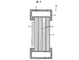
[Embodiment 2]
The following will describe another embodiment of the present invention with reference to FIG. FIG. 6 is a cross-sectional view showing a schematic configuration of the target (E) according to the present embodiment. As shown in FIG. 6, the target (E) according to the present embodiment is different from the first embodiment in that the substrate that supports the metal film 3 is a graphite laminate 8 in which the graphite film 4 is laminated. . When the energy of the accelerated proton beam to be irradiated is relatively high and the amount of heat generated by the irradiation is extremely large, the substrate that supports the metal film 3 may be composed of the graphite laminate 8 as in this embodiment.
グラファイト膜4の膜厚は、1μm以上、100μm以下である。グラファイト積層体8は、複数のグラファイト膜4を加圧下での加熱による接合、または加熱下での加圧による接合により作製することが可能である。すなわち、グラファイト積層体8は、複数枚のグラファイト膜4の加圧接合物または加熱接合物である。このように、金属膜3を支持する基板がグラファイト積層体8により構成されているので、陽子ビームの照射に対する耐久性・耐熱性が増す。
The film thickness of the graphite film 4 is 1 μm or more and 100 μm or less. The graphite laminate 8 can be produced by joining a plurality of graphite films 4 by heating under pressure or by pressure under heating. That is, the graphite laminate 8 is a pressure bonded product or a heated bonded product of a plurality of graphite films 4. Thus, since the substrate that supports the metal film 3 is composed of the graphite laminate 8, the durability and heat resistance against proton beam irradiation are increased.
ターゲット基板としてのグラファイト積層体8の膜厚は、100μm以上、20mm以下であり、より好ましくは200μm以上、10mm以下である。
The film thickness of the graphite laminate 8 as the target substrate is 100 μm or more and 20 mm or less, more preferably 200 μm or more and 10 mm or less.
また、本実施形態にかかるターゲット(E)においても、必要に応じて、図6に示されるように、冷却機構としての冷媒流路6を備えたターゲット支持枠5が取り付けられている事が好ましい。
Moreover, also in the target (E) concerning this embodiment, it is preferable that the target support frame 5 provided with the refrigerant | coolant flow path 6 as a cooling mechanism is attached as needed, as FIG. 6 shows. .
ここで、実施形態2の様に複数のグラファイト膜4を積層することは、加速陽子ビームのエネルギーが比較的高い場合に有用である。加速陽子ビームのエネルギーが高くターゲットが薄すぎる場合には陽子ビームがターゲットを通過してしまう。そのために中性子生成効率が著しく低下するばかりで無く、発生した中性子と陽子ビームが混在することになり好ましくない。さらに、陽子ビームが遮断されるような場合でも、高エネルギーの陽子ビームを用いて中性子を発生させる場合には、ガン治療などの医療用途には有害な速中性子が混じることがある。ターゲット基板は、この様な中性子を減速させる役割も担う場合もあるため、中性子発生用ターゲットには、照射する陽子ビームのエネルギーと発生させる中性子の使用目的にあった厚さのターゲットとする必要がある。
Here, stacking a plurality of graphite films 4 as in the second embodiment is useful when the energy of the accelerated proton beam is relatively high. If the energy of the accelerated proton beam is high and the target is too thin, the proton beam will pass through the target. Therefore, not only the neutron generation efficiency is remarkably lowered but also the generated neutrons and proton beams are mixed, which is not preferable. Furthermore, even when the proton beam is interrupted, if neutrons are generated using a high-energy proton beam, fast neutrons that are harmful to medical applications such as cancer treatment may be mixed. Since the target substrate may also play a role of slowing down such neutrons, the target for neutron generation should be a target with a thickness that matches the energy of the proton beam to be irradiated and the intended use of the generated neutrons. is there.
本実施形態2では、厚さ1μm~100μmの範囲の複数枚のグラファイト膜4を積層して作製するので、基本的に熱伝導や電気伝導特性を損なう事が無く、基本的にどの様な厚さのターゲット基板の作製も可能であり、極めて優れた方法であるといえる。
In the second embodiment, since a plurality of graphite films 4 having a thickness in the range of 1 μm to 100 μm are laminated, the heat conduction and the electric conduction characteristics are basically not impaired, and basically any thickness is obtained. It is possible to produce a target substrate, which is an extremely excellent method.
(圧着積層の方法)
複数枚のグラファイト膜4を積層して、希望する厚さの基板を作製する方法は、特に制限はないが、基板が極めて高い温度に曝されることを考えると、複数枚のグラファイト膜4を、接着剤を用いる事無く、直接加圧・加熱処理によって圧着してグラファイト積層体8を形成することが好ましい。加圧・加熱の条件については、十分な接合強度を持つグラファイト積層体8を形成することができれば特に制限はないが、加熱の温度は200℃~3000℃の範囲、印加圧力は104パスカル以上であり、真空、またはアルゴンや窒素などの不活性ガス中にて加圧・加熱を行うことが好ましい。特に、加圧しながら加熱する、あるいは加熱しながら加圧することは積層体作製の方法として好ましい。また、グラファイト積層体8に用いられるグラファイト膜4は必ずしも完全にグラファイト化されたものである必要はなく、600℃以上、より好ましくは800℃以上、最も好ましくは1000℃以上の温度で炭素化した膜であっても構わない。このように炭素化した膜を積層し、例えば2800℃以上の温度で加熱、加圧すれば目的のターゲット基板を得ることができる。
(Method of pressure lamination)
There is no particular limitation on a method for manufacturing a substrate having a desired thickness by laminating a plurality of graphite films 4, but considering that the substrate is exposed to an extremely high temperature, the plurality of graphite films 4 are formed. It is preferable that the graphite laminate 8 is formed by pressure bonding by direct pressure and heat treatment without using an adhesive. The conditions of pressure and heat, is not particularly limited as long as it can form a graphite laminate 8 with sufficient bonding strength, range of temperature of 200 ° C. ~ 3000 ° C. the heating, the applied pressure is 10 4 Pascal or It is preferable to pressurize and heat in a vacuum or an inert gas such as argon or nitrogen. In particular, heating while applying pressure or applying pressure while heating is preferable as a method for producing a laminate. Further, the graphite film 4 used for the graphite laminate 8 is not necessarily completely graphitized, and is carbonized at a temperature of 600 ° C. or higher, more preferably 800 ° C. or higher, and most preferably 1000 ° C. or higher. It may be a film. By stacking the carbonized films in this way and heating and pressurizing at a temperature of, for example, 2800 ° C. or higher, the target substrate can be obtained.
本発明は上述した各実施形態に限定されるものではなく、請求項に示した範囲で種々の変更が可能であり、異なる実施形態にそれぞれ開示された技術的手段を適宜組み合わせて得られる実施形態についても本発明の技術的範囲に含まれる。さらに、各実施形態にそれぞれ開示された技術的手段を組み合わせることにより、新しい技術的特徴を形成することができる。
The present invention is not limited to the above-described embodiments, and various modifications are possible within the scope shown in the claims, and embodiments obtained by appropriately combining technical means disclosed in different embodiments. Is also included in the technical scope of the present invention. Furthermore, a new technical feature can be formed by combining the technical means disclosed in each embodiment.
〔まとめ〕
本発明の一実施形態に係るターゲットは、少なくとも、ベリリウム材料またはリチウム材料から構成される金属膜と、グラファイト膜から構成される基板と、を有し、加速された陽子を、前記金属膜及び前記基板面に衝突させて中性子を発生させるためのターゲットであって、前記グラファイト膜の膜面方向の熱伝導度は、1500W/(m・K)以上であり、膜面方向の熱伝導度が膜厚方向の熱伝導度の100倍以上であり、前記グラファイト膜の厚さは、1μm以上、100μm以下であることを特徴としている。
[Summary]
A target according to an embodiment of the present invention includes at least a metal film made of a beryllium material or a lithium material, and a substrate made of a graphite film, and accelerated protons are used for the metal film and the metal film. A target for generating neutrons by colliding with a substrate surface, wherein the thermal conductivity in the film surface direction of the graphite film is 1500 W / (m · K) or more, and the thermal conductivity in the film surface direction is a film The thermal conductivity in the thickness direction is 100 times or more, and the thickness of the graphite film is 1 μm or more and 100 μm or less.
上記の構成によれば、前記基板はグラファイト膜から構成されているので、基板の放射化の程度を小さくする事ができる。また、前記グラファイト膜の膜面方向の熱伝導度は、1500W/(m・K)以上であり、膜面方向の熱伝導度が膜厚方向の熱伝導度と比較して100倍以上大きいので、陽子ビームの照射によって発生する熱を速やかに冷却部に移動させる事が出来るため、十分な耐久性を有している。
According to the above configuration, since the substrate is made of a graphite film, the degree of activation of the substrate can be reduced. Further, the thermal conductivity in the film surface direction of the graphite film is 1500 W / (m · K) or more, and the thermal conductivity in the film surface direction is more than 100 times larger than the thermal conductivity in the film thickness direction. Since the heat generated by the irradiation of the proton beam can be quickly moved to the cooling section, it has sufficient durability.
また、前記グラファイト膜の厚さは、1μm以上、100μm以下である。この様な厚さを有するグラファイト膜は、非常に薄いにも関わらず、金属膜を支持する基板としての必要な機械的強度を具備している。
The thickness of the graphite film is 1 μm or more and 100 μm or less. Although the graphite film having such a thickness is very thin, the graphite film has a necessary mechanical strength as a substrate for supporting the metal film.
さらに、この様な薄いターゲットであれば、従来よりも加速エネルギーの低い低放射化の陽子ビームを用いて、医療用途に最適な低エネルギーの熱中性子・熱外中性子を発生させる事が出来る。
Furthermore, with such a thin target, it is possible to generate low-energy thermal neutrons and epithermal neutrons that are optimal for medical use by using a low-activation proton beam that has a lower acceleration energy than before.
本発明の一実施形態に係るターゲットにおいて、前記グラファイト膜の膜面方向の電気伝導度は、16000S/cm以上であり、膜面方向の電気伝導度が膜厚方向の電気伝導度の100倍以上であることが好ましい。
In the target according to an embodiment of the present invention, the electric conductivity in the film surface direction of the graphite film is 16000 S / cm or more, and the electric conductivity in the film surface direction is 100 times or more of the electric conductivity in the film thickness direction. It is preferable that
電気伝導度の測定は、熱伝導度特性の測定と比べて極めて容易であり、電気伝導特性と熱伝導特性は良く比例しているので、電気伝導特性の測定によって、グラファイト膜の基板としての性能を適正に管理することができる。
Measurement of electrical conductivity is much easier than measurement of thermal conductivity characteristics, and the electrical conductivity characteristics and thermal conductivity characteristics are in good proportion to each other. Can be managed properly.
本発明の一実施形態に係るターゲットにおいて、前記基板は、前記グラファイト膜が複数枚積層されたグラファイト積層体から構成され、前記基板の厚さは、100μm以上、20mm以下であることが好ましい。
In the target according to an embodiment of the present invention, the substrate is preferably composed of a graphite laminate in which a plurality of the graphite films are laminated, and the thickness of the substrate is preferably 100 μm or more and 20 mm or less.
上記の構成によれば、前記基板は、前記グラファイト膜が複数枚積層されたグラファイト積層体から構成されているので、熱伝導特性を損なうことなく、より厚い基板を実現することができる。このような、複数枚のグラファイト膜からなる基板は、従来の等方性グラファイトからなる基板よりも薄いにも関わらず、十分な耐久性を有している。これによって比較的高いエネルギーの陽子ビーム照射に対する耐久性、耐熱性が向上し、現在もっぱら医療用に使用されているエネルギー領域の陽子ビームのみならず、さらに高いエネルギーの陽子ビームを用いた中性子発生に対応することができる。
According to the above configuration, since the substrate is composed of a graphite laminate in which a plurality of the graphite films are laminated, a thicker substrate can be realized without impairing heat conduction characteristics. Such a substrate made of a plurality of graphite films has sufficient durability despite being thinner than a conventional substrate made of isotropic graphite. As a result, durability and heat resistance against irradiation of relatively high energy proton beams are improved, and not only proton beams in the energy range currently used for medical purposes but also neutron generation using higher energy proton beams. Can respond.
また、本発明の一実施形態に係るターゲットにおいて、前記グラファイト積層体は、複数枚の前記グラファイト膜の、加圧下での加熱による接合物、または加熱下での加圧による接合物であることが好ましい。
Moreover, in the target according to an embodiment of the present invention, the graphite laminate may be a bonded product of a plurality of the graphite films by heating under pressure, or a bonded product by applying pressure under heating. preferable.
これによって、接着剤等を使用する事無く厚い基板が得られるので、陽子ビームの照射に対する耐久性、耐熱性が向上し、低放射化を実現することができる。
As a result, a thick substrate can be obtained without using an adhesive or the like, so that durability and heat resistance against proton beam irradiation can be improved, and low radiation can be realized.
本発明の一実施形態に係るターゲットにおいて、前記グラファイト膜の密度は、1.60g/cm3以上、2.26g/cm3以下であることが好ましい。
In the target according to an embodiment of the present invention, the density of the graphite film is preferably 1.60 g / cm 3 or more and 2.26 g / cm 3 or less.
本発明のターゲットにおいて、前記グラファイト膜と前記金属膜とが直接接合された構造であることが好ましい。換言すると、前記グラファイト膜に積層された金属からなる金属膜を含むことが好ましい。ここでいう「前記グラファイト膜に積層された金属からなる金属膜」は、前記グラファイト膜に直接接合された金属膜を意味する。
The target of the present invention preferably has a structure in which the graphite film and the metal film are directly bonded. In other words, it is preferable to include a metal film made of metal laminated on the graphite film. The “metal film made of metal laminated on the graphite film” herein means a metal film directly bonded to the graphite film.
本発明の一実施形態に係るターゲットにおいて、前記ターゲットを支持する支持枠を備えたことが好ましい。
The target according to an embodiment of the present invention preferably includes a support frame that supports the target.
上記の構成によれば、前記ターゲットを支持する支持枠を備えたので、ターゲットの機械的強度、耐久性を向上させることができる。
According to the above configuration, since the support frame for supporting the target is provided, the mechanical strength and durability of the target can be improved.
本発明の一実施形態に係るターゲットにおいて前記支持枠は、前記ターゲットを冷却する冷却機構を備えたことが好ましい。
In the target according to an embodiment of the present invention, the support frame preferably includes a cooling mechanism for cooling the target.
これにより、陽子ビームの照射によりターゲットに熱が発生すると、支持枠の冷却機構によって速やかに冷却されるので、ターゲットの耐久性が向上すると共に核反応の効率が上がる。
Thus, when heat is generated in the target by irradiation with the proton beam, it is cooled quickly by the cooling mechanism of the support frame, so that the durability of the target is improved and the efficiency of the nuclear reaction is increased.
本発明の一実施形態に係る中性子発生装置は、陽子を加速するための加速器と、上述のターゲットに対して、前記加速器によって加速された陽子を照射するための陽子照射部と、を備えたことを特徴としている。
A neutron generator according to an embodiment of the present invention includes an accelerator for accelerating protons, and a proton irradiation unit for irradiating the above target with protons accelerated by the accelerator. It is characterized by.
これにより、陽子ビームの照射に対し十分な耐久性、耐熱性を有し、放射化の程度を小さくし得る中性子発生装置を実現することができる。
This makes it possible to realize a neutron generator that has sufficient durability and heat resistance against proton beam irradiation and can reduce the degree of activation.
本発明の一実施形態に係るターゲットの製造方法は、ベリリウム材料またはリチウム材料から構成される金属膜と、グラファイトから構成される1または複数のグラファイト膜と、を有し、陽子を前記金属膜及び前記グラファイト膜の膜面にて衝突させ中性子を発生させるためのターゲットの製造方法であって、前記グラファイト膜を、高分子膜を焼成することにより作製することを特徴としている。
A method for manufacturing a target according to an embodiment of the present invention includes a metal film made of a beryllium material or a lithium material, and one or more graphite films made of graphite. A method of manufacturing a target for generating neutrons by colliding with a film surface of the graphite film, wherein the graphite film is manufactured by firing a polymer film.
上記の構成のように、高分子膜を焼成することにより、前記特性(熱伝導度、電気伝導度、機械的強度、等)を持ち、1μm~100μmの範囲の厚さのグラファイト膜を得ることができる。これにより、陽子ビームの照射に対し十分な耐久性、耐熱性を有し、放射化の程度を小さくし得るターゲットの製造方法を実現することができる。
By baking the polymer film as described above, a graphite film having the above characteristics (thermal conductivity, electrical conductivity, mechanical strength, etc.) and a thickness in the range of 1 μm to 100 μm can be obtained. Can do. Thereby, it is possible to realize a method for manufacturing a target that has sufficient durability and heat resistance against irradiation with a proton beam and can reduce the degree of activation.