EP3447773A1 - Target, target production method, and neutron generation device - Google Patents
Target, target production method, and neutron generation device Download PDFInfo
- Publication number
- EP3447773A1 EP3447773A1 EP17786030.1A EP17786030A EP3447773A1 EP 3447773 A1 EP3447773 A1 EP 3447773A1 EP 17786030 A EP17786030 A EP 17786030A EP 3447773 A1 EP3447773 A1 EP 3447773A1
- Authority
- EP
- European Patent Office
- Prior art keywords
- target
- graphite
- film
- graphite film
- proton
- Prior art date
- Legal status (The legal status is an assumption and is not a legal conclusion. Google has not performed a legal analysis and makes no representation as to the accuracy of the status listed.)
- Granted
Links
- 238000004519 manufacturing process Methods 0.000 title description 2
- OKTJSMMVPCPJKN-UHFFFAOYSA-N Carbon Chemical compound [C] OKTJSMMVPCPJKN-UHFFFAOYSA-N 0.000 claims abstract description 236
- 229910002804 graphite Inorganic materials 0.000 claims abstract description 233
- 239000010439 graphite Substances 0.000 claims abstract description 233
- 229910052751 metal Inorganic materials 0.000 claims abstract description 104
- 239000002184 metal Substances 0.000 claims abstract description 104
- 239000000758 substrate Substances 0.000 claims abstract description 73
- 239000000463 material Substances 0.000 claims description 42
- 238000000034 method Methods 0.000 claims description 39
- 229910052790 beryllium Inorganic materials 0.000 claims description 30
- ATBAMAFKBVZNFJ-UHFFFAOYSA-N beryllium atom Chemical compound [Be] ATBAMAFKBVZNFJ-UHFFFAOYSA-N 0.000 claims description 30
- WHXSMMKQMYFTQS-UHFFFAOYSA-N Lithium Chemical compound [Li] WHXSMMKQMYFTQS-UHFFFAOYSA-N 0.000 claims description 24
- 229910052744 lithium Inorganic materials 0.000 claims description 24
- 238000001816 cooling Methods 0.000 claims description 20
- 230000007246 mechanism Effects 0.000 claims description 14
- 238000010438 heat treatment Methods 0.000 claims description 12
- 238000003825 pressing Methods 0.000 claims description 7
- 238000010304 firing Methods 0.000 claims description 6
- 239000010408 film Substances 0.000 description 268
- 238000006243 chemical reaction Methods 0.000 description 19
- 239000002245 particle Substances 0.000 description 19
- 238000011275 oncology therapy Methods 0.000 description 11
- 239000002131 composite material Substances 0.000 description 10
- 230000002285 radioactive effect Effects 0.000 description 8
- 239000013077 target material Substances 0.000 description 8
- 239000013078 crystal Substances 0.000 description 7
- 125000003118 aryl group Chemical group 0.000 description 6
- 239000002826 coolant Substances 0.000 description 6
- GPRLSGONYQIRFK-UHFFFAOYSA-N hydron Chemical compound [H+] GPRLSGONYQIRFK-UHFFFAOYSA-N 0.000 description 6
- 239000007769 metal material Substances 0.000 description 6
- 229920001721 polyimide Polymers 0.000 description 6
- 239000000523 sample Substances 0.000 description 6
- 238000012360 testing method Methods 0.000 description 6
- IJGRMHOSHXDMSA-UHFFFAOYSA-N Atomic nitrogen Chemical compound N#N IJGRMHOSHXDMSA-UHFFFAOYSA-N 0.000 description 5
- 239000003575 carbonaceous material Substances 0.000 description 5
- 230000007423 decrease Effects 0.000 description 5
- 229910003460 diamond Inorganic materials 0.000 description 5
- 239000010432 diamond Substances 0.000 description 5
- 230000000694 effects Effects 0.000 description 5
- 238000005087 graphitization Methods 0.000 description 5
- 230000020169 heat generation Effects 0.000 description 5
- XKRFYHLGVUSROY-UHFFFAOYSA-N Argon Chemical compound [Ar] XKRFYHLGVUSROY-UHFFFAOYSA-N 0.000 description 4
- -1 HOPG Inorganic materials 0.000 description 4
- 229910052782 aluminium Inorganic materials 0.000 description 4
- XAGFODPZIPBFFR-UHFFFAOYSA-N aluminium Chemical compound [Al] XAGFODPZIPBFFR-UHFFFAOYSA-N 0.000 description 4
- 238000003763 carbonization Methods 0.000 description 4
- 238000010000 carbonizing Methods 0.000 description 4
- 239000000126 substance Substances 0.000 description 4
- 230000037303 wrinkles Effects 0.000 description 4
- 229910000952 Be alloy Inorganic materials 0.000 description 3
- ZOXJGFHDIHLPTG-UHFFFAOYSA-N Boron Chemical compound [B] ZOXJGFHDIHLPTG-UHFFFAOYSA-N 0.000 description 3
- 229910000733 Li alloy Inorganic materials 0.000 description 3
- HBBGRARXTFLTSG-UHFFFAOYSA-N Lithium ion Chemical compound [Li+] HBBGRARXTFLTSG-UHFFFAOYSA-N 0.000 description 3
- 230000001133 acceleration Effects 0.000 description 3
- 230000008901 benefit Effects 0.000 description 3
- 150000001573 beryllium compounds Chemical class 0.000 description 3
- 229910052796 boron Inorganic materials 0.000 description 3
- 229910052799 carbon Inorganic materials 0.000 description 3
- 150000001875 compounds Chemical class 0.000 description 3
- 230000003247 decreasing effect Effects 0.000 description 3
- 229910021397 glassy carbon Inorganic materials 0.000 description 3
- 239000007770 graphite material Substances 0.000 description 3
- 230000017525 heat dissipation Effects 0.000 description 3
- 239000011261 inert gas Substances 0.000 description 3
- 239000001989 lithium alloy Substances 0.000 description 3
- 150000002642 lithium compounds Chemical class 0.000 description 3
- 238000005259 measurement Methods 0.000 description 3
- 229910052755 nonmetal Inorganic materials 0.000 description 3
- 230000008569 process Effects 0.000 description 3
- 230000009467 reduction Effects 0.000 description 3
- 238000002560 therapeutic procedure Methods 0.000 description 3
- 239000000853 adhesive Substances 0.000 description 2
- 230000001070 adhesive effect Effects 0.000 description 2
- 229910052786 argon Inorganic materials 0.000 description 2
- 125000004429 atom Chemical group 0.000 description 2
- PWOSZCQLSAMRQW-UHFFFAOYSA-N beryllium(2+) Chemical compound [Be+2] PWOSZCQLSAMRQW-UHFFFAOYSA-N 0.000 description 2
- 239000006227 byproduct Substances 0.000 description 2
- 239000011248 coating agent Substances 0.000 description 2
- 238000000576 coating method Methods 0.000 description 2
- 239000000470 constituent Substances 0.000 description 2
- 239000000498 cooling water Substances 0.000 description 2
- 238000004980 dosimetry Methods 0.000 description 2
- 229910052757 nitrogen Inorganic materials 0.000 description 2
- 230000005855 radiation Effects 0.000 description 2
- 238000011160 research Methods 0.000 description 2
- 102100037364 Craniofacial development protein 1 Human genes 0.000 description 1
- 206010073306 Exposure to radiation Diseases 0.000 description 1
- 101000880187 Homo sapiens Craniofacial development protein 1 Proteins 0.000 description 1
- OAICVXFJPJFONN-UHFFFAOYSA-N Phosphorus Chemical compound [P] OAICVXFJPJFONN-UHFFFAOYSA-N 0.000 description 1
- 239000004642 Polyimide Substances 0.000 description 1
- XUIMIQQOPSSXEZ-UHFFFAOYSA-N Silicon Chemical compound [Si] XUIMIQQOPSSXEZ-UHFFFAOYSA-N 0.000 description 1
- NINIDFKCEFEMDL-UHFFFAOYSA-N Sulfur Chemical compound [S] NINIDFKCEFEMDL-UHFFFAOYSA-N 0.000 description 1
- RTAQQCXQSZGOHL-UHFFFAOYSA-N Titanium Chemical compound [Ti] RTAQQCXQSZGOHL-UHFFFAOYSA-N 0.000 description 1
- YZCKVEUIGOORGS-NJFSPNSNSA-N Tritium Chemical compound [3H] YZCKVEUIGOORGS-NJFSPNSNSA-N 0.000 description 1
- 238000004458 analytical method Methods 0.000 description 1
- 239000004760 aramid Substances 0.000 description 1
- 229920003235 aromatic polyamide Polymers 0.000 description 1
- QVGXLLKOCUKJST-UHFFFAOYSA-N atomic oxygen Chemical compound [O] QVGXLLKOCUKJST-UHFFFAOYSA-N 0.000 description 1
- 238000005452 bending Methods 0.000 description 1
- 230000008859 change Effects 0.000 description 1
- 239000012141 concentrate Substances 0.000 description 1
- 238000007796 conventional method Methods 0.000 description 1
- 238000005260 corrosion Methods 0.000 description 1
- 230000007797 corrosion Effects 0.000 description 1
- 238000009792 diffusion process Methods 0.000 description 1
- 229910001873 dinitrogen Inorganic materials 0.000 description 1
- 238000005530 etching Methods 0.000 description 1
- 230000005284 excitation Effects 0.000 description 1
- 239000007789 gas Substances 0.000 description 1
- 229910001385 heavy metal Inorganic materials 0.000 description 1
- 239000001307 helium Substances 0.000 description 1
- 229910052734 helium Inorganic materials 0.000 description 1
- SWQJXJOGLNCZEY-UHFFFAOYSA-N helium atom Chemical compound [He] SWQJXJOGLNCZEY-UHFFFAOYSA-N 0.000 description 1
- 238000007731 hot pressing Methods 0.000 description 1
- 229910052739 hydrogen Inorganic materials 0.000 description 1
- 239000001257 hydrogen Substances 0.000 description 1
- 125000004435 hydrogen atom Chemical group [H]* 0.000 description 1
- 230000003993 interaction Effects 0.000 description 1
- 230000001788 irregular Effects 0.000 description 1
- 238000010030 laminating Methods 0.000 description 1
- 238000000608 laser ablation Methods 0.000 description 1
- 239000007788 liquid Substances 0.000 description 1
- 238000002156 mixing Methods 0.000 description 1
- 238000000465 moulding Methods 0.000 description 1
- 238000010525 oxidative degradation reaction Methods 0.000 description 1
- 230000001590 oxidative effect Effects 0.000 description 1
- 229910052760 oxygen Inorganic materials 0.000 description 1
- 239000001301 oxygen Substances 0.000 description 1
- 229920001277 pectin Polymers 0.000 description 1
- 230000002093 peripheral effect Effects 0.000 description 1
- 239000011574 phosphorus Substances 0.000 description 1
- 229910052698 phosphorus Inorganic materials 0.000 description 1
- 229920002480 polybenzimidazole Polymers 0.000 description 1
- 229920002577 polybenzoxazole Polymers 0.000 description 1
- 229920000642 polymer Polymers 0.000 description 1
- 239000000843 powder Substances 0.000 description 1
- 230000002265 prevention Effects 0.000 description 1
- 239000000941 radioactive substance Substances 0.000 description 1
- 239000002901 radioactive waste Substances 0.000 description 1
- 239000002994 raw material Substances 0.000 description 1
- 230000004044 response Effects 0.000 description 1
- 229910052710 silicon Inorganic materials 0.000 description 1
- 239000010703 silicon Substances 0.000 description 1
- 239000007787 solid Substances 0.000 description 1
- 239000007858 starting material Substances 0.000 description 1
- 229910052717 sulfur Inorganic materials 0.000 description 1
- 239000011593 sulfur Substances 0.000 description 1
- 238000002076 thermal analysis method Methods 0.000 description 1
- 239000010409 thin film Substances 0.000 description 1
- 239000010936 titanium Substances 0.000 description 1
- 229910052719 titanium Inorganic materials 0.000 description 1
- 231100000331 toxic Toxicity 0.000 description 1
- 230000002588 toxic effect Effects 0.000 description 1
- 238000012546 transfer Methods 0.000 description 1
- 229910052722 tritium Inorganic materials 0.000 description 1
- 238000007740 vapor deposition Methods 0.000 description 1
Images


Classifications
-
- G—PHYSICS
- G21—NUCLEAR PHYSICS; NUCLEAR ENGINEERING
- G21G—CONVERSION OF CHEMICAL ELEMENTS; RADIOACTIVE SOURCES
- G21G4/00—Radioactive sources
- G21G4/02—Neutron sources
-
- G—PHYSICS
- G21—NUCLEAR PHYSICS; NUCLEAR ENGINEERING
- G21K—TECHNIQUES FOR HANDLING PARTICLES OR IONISING RADIATION NOT OTHERWISE PROVIDED FOR; IRRADIATION DEVICES; GAMMA RAY OR X-RAY MICROSCOPES
- G21K5/00—Irradiation devices
- G21K5/04—Irradiation devices with beam-forming means
-
- G—PHYSICS
- G21—NUCLEAR PHYSICS; NUCLEAR ENGINEERING
- G21K—TECHNIQUES FOR HANDLING PARTICLES OR IONISING RADIATION NOT OTHERWISE PROVIDED FOR; IRRADIATION DEVICES; GAMMA RAY OR X-RAY MICROSCOPES
- G21K5/00—Irradiation devices
- G21K5/08—Holders for targets or for other objects to be irradiated
-
- H—ELECTRICITY
- H05—ELECTRIC TECHNIQUES NOT OTHERWISE PROVIDED FOR
- H05H—PLASMA TECHNIQUE; PRODUCTION OF ACCELERATED ELECTRICALLY-CHARGED PARTICLES OR OF NEUTRONS; PRODUCTION OR ACCELERATION OF NEUTRAL MOLECULAR OR ATOMIC BEAMS
- H05H3/00—Production or acceleration of neutral particle beams, e.g. molecular or atomic beams
- H05H3/06—Generating neutron beams
-
- H—ELECTRICITY
- H05—ELECTRIC TECHNIQUES NOT OTHERWISE PROVIDED FOR
- H05H—PLASMA TECHNIQUE; PRODUCTION OF ACCELERATED ELECTRICALLY-CHARGED PARTICLES OR OF NEUTRONS; PRODUCTION OR ACCELERATION OF NEUTRAL MOLECULAR OR ATOMIC BEAMS
- H05H6/00—Targets for producing nuclear reactions
Definitions
- the present invention relates to a target, a method of producing a target, and a neutron generator.
- Patent Literature 1 discloses an accelerator neutron source for neutron generation for boron neutron capture therapy.
- the accelerator neutron source disclosed in Patent Literature 1 includes: a metal target in a plate shape for irradiation with a charged particle beam (proton beam); and a cooling apparatus for cooling the metal target.
- the metal target in a plate shape is irradiated with a charged particle beam accelerated by the accelerator, and thereby neutrons are generated.
- the metal target is cooled by the cooling apparatus.
- the conventional targets for neutron generation configured such that a metal target is disposed on a substrate as described above, however, have issues in that they have poor durability and poor heat resistance against proton beams.
- a target including a cooling mechanism for example, a flow channel for passage of cooling water
- the metal plate including a cooling mechanism is made of aluminum.
- the half-life of aluminum is 300,000 years, which means that aluminum becomes radioactive to an extremely large extent. Highly radioactive targets cannot be handled by humans. This leads to difficulty in irradiation with high-energy proton beams and continuous use of the beams.
- Patent Literatures 2, 4, and 5 disclose specific examples of such a carbon material, such as isotropic graphite materials, single-crystal graphite, HOPG, glassy carbon, single-crystal diamond, and epitaxial diamond.
- a target for neutron generation in reality is required to be large enough for actual use, that is, for example, the target needs to be about 10 mm to 500 mm in diameter.
- the present invention was made in view of the above issues, and an object thereof is to provide a target that is much thinner than conventional targets, that is sufficiently durable and sufficiently heat-resistant against a large quantity of heat generated by proton beam irradiation, and that can reduce the extent of radioactivation, a method of producing a target, and a neutron generator.
- a method of producing a target of another aspect of the present invention is a method of producing a target that includes: a metal film composed of a beryllium material or a lithium material; and one or more graphite films composed of graphite, the target being configured to generate a neutron upon collision of a proton with a surface of the metal film and a surface of the graphite film, the method including a step of preparing the one or more graphite films by firing one or more polymeric films.
- conventionally used materials for a substrate for supporting a metal target are carbon materials, isotropic graphite, aluminum (Al), and the like.
- graphite which becomes radioactive only to a relatively small extent and which is resistant to heat (3000°C) in vacuum, is an ideal material, and isotropic graphite materials have been conventionally used as carbon substrates.
- isotropic graphite substrates are far from sufficient in terms of durability and heat resistance against high-energy proton beams for the foregoing reasons, and there has been a strong demand for targets with higher durability.
- Such a graphite substrate of an embodiment of the present invention was found to be sufficiently durable to serve as a target substrate, despite that it is a thin film much thinner than the substrate thickness required for conventional isotropic graphite substrates and the like.
- the greatest benefit of a thin target substrate is that low-energy, less-harmful thermal and epithermal neutrons can be efficiently generated by irradiation with a proton beam accelerated only to an energy lower than conventional. Such thermal and epithermal neutrons are useful for medical applications such as cancer therapy.
- the second benefit of using a proton beam accelerated only to a low energy is that the extent of radioactivation of the target by the proton beam can be reduced, and the third benefit is that the accelerator itself can be reduced in size.
- a reduction in thickness of a graphite substrate leads not only to a reduction in mechanical strength but also to an increase in heat load per unit volume induced by proton beam irradiation. This results in requirements of the same level of durability and heat resistance both in the case of a proton beam accelerated only to a low energy and in the case of a proton beam accelerated to a high energy. Therefore, it has been thought that thin carbon or thin graphite is not enough to serve as a neutron generation substrate.
- the inventors did several researches on their own and established a technique to produce a graphite film that has excellent properties such as excellent thermal conductivity.
- the inventors also found that the mechanical strength that is enough to serve as a substrate can be achieved, provided that the range of from 100 ⁇ m to 1 ⁇ m is satisfied.
- this graphite film can withstand the heat load generated by irradiation with a proton beam, despite being 100 ⁇ m or less in thickness.
- a thin target enables use of a proton beam accelerated only to a low energy (about 2 MeV to 6 MeV), as described earlier. This makes it possible to reduce the extent of radioactivation of the target. Furthermore, since a neutron beam produced with the use of such protons accelerated only to a low energy does not contain harmful fast neutrons, a neutron generation target or apparatus using such a neutron beam are suitable for medical use such as cancer therapy.
- the technical idea of the present invention based on the above finding reverses conventional findings, and is not the one that is predictable from conventional findings but the one that has been accomplished by the inventors themselves.
- the metal film 3 whose surface collides with the proton beam, is composed of a beryllium material or a lithium material. With this configuration, the metal film 3 is capable of generating a low-energy neutron 2 upon collision with a low-energy proton beam.
- the term “beryllium material” refers to a single element material of beryllium element, a beryllium compound, a beryllium alloy, or a beryllium composite material.
- the term “lithium material” refers to a single element material of lithium element (metal consists only of lithium element, hereinafter referred to as lithium), a lithium compound, a lithium alloy, or a lithium composite material.
- beryllium, beryllium compounds, beryllium alloys, and beryllium composite materials are collectively referred to as "beryllium materials” and lithium, lithium compounds, lithium alloys, and lithium composite materials are collectively referred to as “lithium materials” is that the principle of neutron generation is based on a nuclear reaction that is specific to a specific element.
- the principle of neutron generation caused by irradiation of a target with an accelerated proton beam is based on a physical nuclear reaction between the proton beam and atoms of a specific element contained in the target, and thus, also in a case where the target is composed of a compound of the specific element or a composite material of the specific element, the neutrons are generated through a similar nuclear reaction to the case of a simple substance of the specific element.
- beryllium compounds, beryllium alloys, beryllium composite materials, lithium compounds, lithium alloys, and lithium composite materials can be used, as well as beryllium and lithium.
- the elements other than the specific element contained in the compound or the composite material are those which are not radioactivated by protons or neutrons or which do not produce any harmful substance through the reaction with by-product hydrogen atoms.
- examples of such elements include, but are not limited to, carbon, silicon, nitrogen, phosphorus, oxygen, and sulfur.
- the opposite side of the metal film 3 from the graphite film 4 faces the direction of travel of protons.
- Such an arrangement achieves the following: when a metal film 3 having a thickness that is thinner than the theoretical range of proton is employed, some protons undergo a nuclear reaction while passing through the metal film 3 and other protons undergo a nuclear reaction while passing through the graphite film 4. With this arrangement, the heat load resulting from the nuclear reactions does not concentrate in one material. This makes it possible to reduce the heat load that the materials experience.
- the metal film 3 of the target (A) can have a thickness that is much less than the theoretical range of proton in beryllium or lithium. This is because the graphite film 4 serves to support and cool the metal film 3 and thereby the heat loads that the metal film 3 and the graphite film 4 experience are reduced.
- the area of the surface of the metal film 3 irradiated with proton can be determined appropriately depending on the power setting of the proton.
- the maximum value of heat load per unit area of a target substrate is represented by a value obtained by dividing the output power of proton by the area irradiated with the proton.
- the metal film 3 is designed such that its ability to release heat from a surface is equal to or greater than the heat load that the target (A) experiences.
- the output power of proton necessary for generation of neutron for medial use such as BNCT is calculated to be about 30 kW at maximum.
- the heat load is calculated to be about 10 MW/m 2 .
- This heat load is equivalent to heat that raises the temperature of beryllium by about 3000°C per second, in a case where the metal film serving as a neutron generation target is a beryllium film having a thickness of 1 mm and a surface area of 30cm 2 .
- the surface area of the metal film 3 is preferably equal to or larger than a plane area perpendicular to the direction of travel of proton, for reducing the foregoing large heat load.
- the heat load per unit plane area of the metal film 3 irradiated with the proton is reduced to equal to or less than one-half.
- the surface area of the metal film 3 can be increased, for example, by imparting irregularities to the surface of the metal film 3, by causing a graphite film 4 having irregularities on its surface and serving as a substrate to support the metal film 3, by coating powder on the metal film 3, or the like method.
- the surface of the beryllium material can be fabricated by, for example, laser ablation, etching, molding, or the like method.
- the term "plane area" refers to the area of proton beam spot on a surface of the metal film 3, assuming that the surface is flat.
- neutrons are generated through collision of low-energy protons with the target (A), which is constituted by the metal film 3 and the graphite film 4.
- the target (A) which is constituted by the metal film 3 and the graphite film 4.
- the nuclear reaction 9 Be(p,n) takes place in the metal film 3 of the target (A).
- the nuclear reaction 6 Li(p,n) or 7 Li(p,n) takes place in the metal film 3 of the target (A).
- the nuclear reaction 12 C(p,n) takes place in the graphite film 4 of the target (A).
- the graphite film 4 is suitable in order to reduce the extent of radioactivation resulting from incident protons and generated neutrons and to produce low-energy neutrons with a reduced amount of fast neutrons that are harmful and that have the high ability to cause radioactivation.
- Graphite is a material that is highly efficient in generating neutrons and that does not easily become radioactive, absorbs few thermal and epithermal neutrons, and is highly effective in decelerating neutrons.
- the target (A) which is constituted by the foregoing metal film 3 and graphite film 4, is sufficiently durable and sufficiently heat-resistant against irradiation with the proton beam 1, despite that the target (A) is much thinner than conventional targets.
- This target is not so effective in decelerating generated neutrons. However, this makes it possible to obtain desired low-energy thermal and epithermal neutrons by irradiation with the low-energy proton beam 1.
- neutrons can be generated with the use of a low-energy proton beam. This makes it possible to dramatically reduce the extent of radioactivation.
- a method of producing a graphite film 4 in accordance with Embodiment 1 is not particularly limited, and is, for example, a method of preparing a graphite film 4 by treating a polymeric film with heat (e.g., by firing a polymeric film).
- this method it is possible to prepare graphite in the form of a large-area film, and, for example, it is even possible to easily prepare a film having an area of 300 mm in diameter.
- this production method does not involve any issue from the practical point of view, as compared to carbon materials disclosed as target substrates in the foregoing Patent Literatures, such as HOPG, single-crystal graphite, and diamond.
- a method of producing a graphite film 4 of one example of Embodiment 1 includes a carbonizing step including carbonizing an aromatic polyimide film and a graphitizing step including graphitizing the carbonized aromatic polyimide film.
- the carbonizing step involves carrying out carbonization by preheating an aromatic polyimide film, which is a starting material, under reduced pressure or in nitrogen gas.
- the heat treatment temperature for carbonization is preferably 500°C or above, more preferably at 600°C or above, most preferably 700°C or above.
- graphitization may be carried out after removing the carbonized polyimide film from a furnace and then transferring it to a graphitization furnace, or carbonization and graphitization may be carried out continuously.
- the graphitization is carried out under reduced pressure or in an inert gas. Suitable inert gases are argon and helium.
- the treatment may be carried out until the heat treatment temperature (firing temperature) reaches 2400°C or above, preferably 2600°C or above, more preferably 2800°C or above.
- wrinkles may appear.
- the wrinkles are not an issue at all in applications of the present invention.
- the wrinkles in the graphite film 4 would rather contribute to an increase in surface area of the metal film 3, due to the irregular surface resulting from the wrinkles. It follows that the area irradiated with the proton beam 1 increases, and neutron generation efficiency increases. This is preferred.
- a polymeric film for use in Embodiment 1 is a polymeric film of at least one polymer selected from aromatic polyimides, aromatic polyamides, polyoxadiazoles, polybenzothiazoles, polybenzobisthiazoles, polybenzoxazoles, polybenzobisoxasoles, polyparaphenylene vinylenes, polybenzimidazoles, polybenzobisimidazoles, and aromatic polythiazoles.
- a particularly preferable raw material film for the graphite film 4 of Embodiment 1 is an aromatic polyimide film.
- the thermal conductivity in a surface direction of the graphite film 4 in Embodiment 1 is equal to or greater than 1500 W/(m ⁇ K), preferably equal to or greater than 1600 W/(m ⁇ K), more preferably equal to or greater than 1700 W/(m ⁇ K).
- a graphite film 4 having a thermal conductivity in the surface direction of 1500 W/(m ⁇ K) or greater provides multilayer graphite having a better heat dissipation performance.
- a graphite film 4 having a thermal conductivity in the surface direction of 1500 W/(m ⁇ K) or grater is much higher in thermal conductivity than the metal film 3, and therefore is capable of quickly diffusing, in the surface direction, heat generated in the metal film 3 and guiding the heat to a frame having a cooling function (refer to Figs. 3 and 4 ).
- the thermal conductivity in the thickness direction of the graphite film 4 can be calculated in the same manner as described above using the foregoing equation (1), except that ⁇ in the equation is the thermal diffusivity in the thickness direction of the graphite film 4.
- the thermal diffusivity in the thickness direction of the graphite film 4 is determined by a pulse heating method using a laser.
- a laser is shined on one surface of the film and thereby the film is heated, and thereafter a temperature response (temperature change) at the opposite surface of the film is measured.
- ⁇ thermal diffusivity
- ⁇ 0 the period of thermal diffusion
- d represents the thickness of a sample
- t 1/2 represents half-time
- 0.1388 is the apparatus constant of the apparatus used.
- the thickness of the graphite film 4 in Embodiment 1 is 1 ⁇ m or greater and 100 ⁇ m or less, more preferably 2 ⁇ m or greater and 100 ⁇ m or less, particularly preferably 10 ⁇ m or greater and 100 ⁇ m or less.
- a graphite film 4 having such a thickness has a sufficient mechanical strength to serve as a substrate, and provides high thermal conductivity characteristics in the surface direction (equal to or greater than 1500 W/mK).
- the thickness of the graphite film 4 is measured in the following manner: thicknesses at any ten locations of a sample measuring 50 mm ⁇ 50 mm cut from the graphite film 4 are measured in a thermostatic chamber at 25°C with the use of a thickness gage (HEIDENHAIN-CERTO, manufactured by HEIDENHAIN); and the mean of the thicknesses is used as the thickness of the graphite film 4.
- HEIDENHAIN-CERTO manufactured by HEIDENHAIN
- the electric conductivity in the surface direction of the graphite film 4 in Embodiment 1 is preferably 16000 S/cm or greater, preferably 17000 S/cm or greater, most preferably 18000 S/cm or greater.
- the graphite film 4 preferably has anisotropy (orientation) such that the electric conductivity in the surface direction of the graphite film 4 is equal to or greater than 100 times the electric conductivity in the thickness direction of the graphite film 4.
- the electrical conductivity of the graphite film 4 is measured by applying a constant current in a four-point probe method (for example, by using Loresta-GP, manufactured by Mitsubishi Chemical Analytech Co., Ltd.)
- the graphite film 4 preferably has a higher density, because a higher density provides better self-supporting property and better mechanical strength characteristics. Furthermore, a graphite film 4 having a greater density causes a greater interaction with a charged particle beam, and thus provides a greater neutron decelerating effect. In addition, a graphite film 4 having a high density has little gap between its constituent graphite layers, and therefore such a graphite film 4 tends to have a high thermal conductivity.
- a graphite film 4 has a low density
- such a graphite film 4 has a poor efficiency in decelerating a charged particle beam
- the graphite film 4 also has a decreased thermal conductivity due to the effects of air layers between the constituent graphite layers. This is therefore not preferred.
- thermal conductivity is poor and thus heat is likely to be trapped in these portions, or that the air layers in the hollow portions expand due to temperature increase caused by heat. Therefore, a graphite film 4 having a low density easily deteriorates and/or is damaged.
- the graphite film 4 preferably has a high density.
- the density is preferably 1.60 g/cm 3 or greater, preferably 1.70 g/cm 3 or greater, more preferably 1.80 g/cm 3 or greater, more preferably 2.00 g/cm 3 or greater, most preferably 2.10 g/cm 3 or greater.
- the density of the graphite film 4 is 2.26 g/cm 3 (theoretical value) or less, and may be 2.25 g/cm 3 or less.
- the density of the graphite film 4 is measured in the following manner: a sample measuring 100 mm ⁇ 100 mm cut from the graphite film 4 is measured for weight and thickness; and the measured value of the weight is divided by the value of volume (calculated from 100 mm ⁇ 100 mm ⁇ thickness).
- the mechanical strength of the graphite film 4 can be estimated by performing an MIT folding endurance test on the graphite film 4, in a case where the graphite film 4 is equal to or less than 100 ⁇ m in thickness.
- the number of times the graphite film 4 is folded in the MIT folding endurance test may be preferably 500 or more, more preferably 1000 or more, even more preferably 2000 or more.
- the MIT folding endurance test for the graphite film 4 is carried out in the following manner. Three test pieces each measuring 1.5 ⁇ 10 cm are removed from the graphite film 4. The test is carried out with the use of an MIT crease-flex fatigue resistance tester Model D manufactured by Toyo Seiki Seisaku-sho, Ltd.
- test load is 100 gf (0.98 N)
- speed is 90 times/min.
- radius of curvature R of folding clamp is 2 mm.
- the graphite film 4 is folded to an angle of 135° in either direction in an atmosphere of 23°C, and the number of times the graphite film 4 is folded before the graphite film 4 is severed is counted.
- a graphite substrate equal to or greater than 100 ⁇ m in thickness has a sufficient mechanical strength and thus mechanical strength is not an issue.
- Fig. 2 is a cross-sectional view illustrating a variation of the target in accordance with Embodiment 1.
- a target (B) which is Variation 1
- the target support frame 5 is a frame that supports at least the peripheral portion of the graphite film 4, and is preferably composed of a metal because the metal has excellent mechanical strength, excellent thermal conductivity, and excellent durability.
- the target (B) of Variation 1 is supported by the target support frame 5.
- This makes it possible to achieve a cartridge-type structure (cassette-type structure) that makes the target (B) easily attachable/detachable.
- the target support frame 5 is composed of a metal, heat generated in the target (B) can be easily guided through the target support frame 5 to a separately provided cooling mechanism.
- Fig. 3 is a cross-sectional view illustrating another variation of the target in accordance with Embodiment 1.
- a target (C) which is Variation 2
- a coolant for passage through the coolant flow channel 6 is a liquid with a high thermal conductivity such as cooling water, or a gas.
- the target support frame 5 since the target support frame 5 has the coolant flow channel 6 therein, heat generated in the target (C) is quickly cooled by the coolant flow channel 6 serving as a cooling mechanism provided in the target support frame 5. This improves the durability of the target (C) and also improves nuclear reaction efficiency.
- the collision stopping power (energy loss) of a target material (in this case, the graphite film 4) for a charged particle (proton) is represented by the following Bethe equation (equation (3)):
- S col ⁇ 4 ⁇ ⁇ e 4 z 2 N mv 2 Z ln 2 mv 2 I 1 ⁇ ⁇ 2 ⁇ ⁇ 2
- e represents elementary charge of electron
- m represents mass of electron
- v velocity of electron
- z nuclear charge of incident particle
- Z represents the atomic number of the target material
- N represents the number of atoms per unit volume of the target material
- I represents the mean excitation potential of the target material
- ⁇ represents v/c where c is the speed of light.
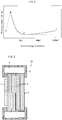
- Fig. 5 is a graph showing the relationship between the stopping power based on the Bethe equation (equation (3)) and kinetic energy of particle.
- the collision stopping power (energy loss) of a target material for a charged particle increases from A (kinetic energy of particle is low) to B and reaches maximum at B.
- the stopping power decreases from B to C in proportion to I/v 2 , and reaches minimum at C.
- the stopping power gradually increases from C to D, where logarithms of the Bethe equation (equation (3)) are effective.
- the heat generation caused by irradiation with an accelerated proton beam is not reduced even when the energy of the accelerated proton beam is small, and therefore, even in the case of irradiation with a low-energy proton beam, the target is required to have high durability.
- a method of generating neutrons in accordance with Embodiment 1 involves generating low-energy neutrons with a reduced amount of fast neutrons that are harmful and that have the high ability to cause radioactivation, through collision of low-energy protons with a target in vacuum.
- the target used in Embodiment 1 is a substrate constituted by: a graphite film 4 having the foregoing properties; and a metal film 3 that is attached to one side of the graphite film 4 and that is equal to or greater than 10 ⁇ m and less than 1 mm in thickness.
- a surface of the metal film 3, that is, the surface located at a target's surface, is arranged so as to face the direction of travel of proton. This is in order to allow a nuclear reaction between proton and metal to take place first.
- Neutrons that can be generated by the method of generating neutrons in accordance with Embodiment 1 are low-energy neutrons including large amounts of thermal neutrons or epithermal neutrons.
- Low-energy neutrons refer to neutrons with a reduced amount of fast-neutrons that are harmful and that have the high ability to cause radioactivation.
- Fast neutrons are 100 times or more as high in energy as thermal neutrons or epithermal neutrons, and therefore are biologically harmful and have the very high ability to cause radioactivation.
- Neutron is categorized into fast neutron, epithermal neutron, thermal neutron, and cold neutron.
- epithermal neutron usually refers to neutron falling within the energy range of from 1 eV to 10 keV
- thermal neutron usually refers to neutron falling within the energy range of equal to and less than 0.5 eV.
- low-energy neutron refers to neutron with a reduced amount of fast neutron of 0.5 MeV or greater.
- the energy of incident proton is greater than 8 MeV
- neutron of 5 MeV or greater may be contained; however, the amount of such neutron can be reduced significantly as compared to conventional primary neutron.
- a neutron generator in accordance with Embodiment 1 includes a target, a hydrogen ion generator, a linear accelerator, and a proton emitting section.
- An accelerator for generating protons in a neutron generator is a linear accelerator.
- a large accelerator such as a synchrotron or a cyclotron is used in order to use, as proton for collision with a target, high-energy proton of 11 MeV or greater.
- mainly used proton is equal to or greater than 2 MeV and less than 11 MeV. Therefore, a linear accelerator is sufficient to generate desired large-current proton.
- the linear accelerator includes the hydrogen ion generator at one end thereof. Hydrogen ions from the hydrogen ion generator enter an acceleration cavity through a charged particle converting film and are accelerated.
- the hydrogen ion generator is not particularly limited, and can be, for example, a conventional proton generator, a conventional negative hydrogen ion generator, or the like.
- the acceleration cavity can be a radio frequency accelerating cavity, a DC acceleration cavity, a normal conducting accelerating cavity, a superconducting accelerating cavity, or the like.
- the proton beam emitting section is provided on the opposite side of the linear accelerator from the hydrogen ion generator.
- the proton beam emitting section is provided between the linear accelerator and the target.
- the proton emitting section is not particularly limited, and can be a conventional proton emitting section that includes a quadrupole electromagnet and a bending magnet.
- the protons accelerated by the linear accelerator are guided to the proton emitting section connected at an end of the linear accelerator, and collide with the target at an end of the proton emitting section. Through this collision, low-energy neutrons are generated.
- the targets (B) to (D) each include a metal film 3, a graphite film 4, and a target support frame 5 that has a cooling function.
- the neutron generator in accordance with Embodiment 1 may employ the following arrangement: a target (B), (C), or (D), which has a cartridge-type structure, is provided at an end of the proton emitting section with a vacuum flange therebetween which has a semiautomatic detach/attach structure. This makes it possible to easily replace a deteriorated target with a new target by detaching the deteriorated target and attaching the new target via remote control.
- a neutron generator in accordance with Embodiment 1 can also be installed in small-scale medical institutions as a medical neutron generator for generation of neutron for medical purposes such as BNCT.
- a substrate that supports a metal film 3 may be constituted by a graphite stack 8 as described in Embodiment 2.
- each of the graphite films 4 is equal to or greater than 1 ⁇ m and equal to or less than 100 ⁇ m.
- the graphite stack 8 can be prepared by uniting a plurality of graphite films 4 by heating the graphite films 4 under pressure or by uniting a plurality of graphite films 4 by pressing the graphite films 4 under heat. That is, the graphite stack 8 is a laminate of a plurality of graphite films 4 united together by means of pressure or heat. Since the substrate that supports the metal film 3 is constituted by the graphite stack 8 as described above, durability and heat resistance against proton beam irradiation improve.
- the thickness of the graphite stack 8, which serves as a target substrate, is equal to or greater than 100 ⁇ m and equal to or less than 20 mm, more preferably equal to or greater than 200 ⁇ m and equal to or less than 10 mm.
- the target (E) in accordance with Embodiment 2 also preferably has a target support frame 5 attached thereto as illustrated in Fig. 6 , depending on need.
- the target support frame 5 has a flow channel 6 serving as a cooling mechanism.
- stacking a plurality of graphite films 4 like Embodiment 2 is useful in a case where the energy of an accelerated proton beam is relatively high. If the energy of an accelerated proton beam is high and a target is too thin, the proton beam unintentionally passes through the target. This not only dramatically reduces neutron generation efficiency but also causes mixing of generated neutrons and a proton beam, and thus is not preferred. Furthermore, even in a case where the proton beam is shielded against, fast neutrons that are harmful in medical applications such as cancer therapy may be mixed in the generated neutrons if neutron generation is carried out using a high-energy proton beam.
- the target substrate in some cases serves also to decelerate such neutrons, and therefore a target for neutron generation is required to have a thickness that is suitable for the energy of a proton beam with which the target is irradiated and that is suitable for the intended purpose of generated neutrons.
- the graphite stack 8 is prepared by stacking together a plurality of graphite films 4 each having a thickness in the range of from 1 ⁇ m to 100 ⁇ m. Therefore, thermal conductivity or electric conductivity characteristics are basically not lost, and basically a target substrate of any thickness can be prepared. Embodiment 2 thus provides a very superior method.
- the conditions under which the graphite films 4 are pressed and/or heated are not limited, provided that the graphite films 4 constituting the resulting graphite stack 8 are sufficiently strongly united together, but the graphite films 4 are pressed and/or heated preferably in vacuum or in an inert gas such as argon or nitrogen under the conditions in which heating temperature is in the range of from 200°C to 3000°C and applied pressure is equal to or greater than 10 4 pascals. Heating while pressing or pressing while heating is particularly preferred as a method of preparing a laminate.
- the graphite films 4 constituting the graphite stack 8 do not necessarily have to be fully graphitized, and may be films carbonized at a temperature equal to or above 600°C, more preferably equal to or above 800°C, most preferably equal to or above 1000°C. By stacking such carbonized films and, for example, heating the films and/or pressing the films at a temperature equal to or above 2800°C, it is possible to obtain a desired target substrate.
- the present invention is not limited to the embodiments, but can be altered by a skilled person in the art within the scope of the claims.
- the present invention also encompasses, in its technical scope, any embodiment derived by combining technical means disclosed in differing embodiments. Further, it is possible to form a new technical feature by combining the technical means disclosed in the respective embodiments.
- the substrate is constituted by a graphite film.
- the graphite film has a thermal conductivity in a surface direction of 1500 W/(m ⁇ K) or greater, and the thermal conductivity in the surface direction of the graphite film is equal to or greater than 100 times a thermal conductivity in a thickness direction of the graphite film. This makes it possible to quickly transfer the heat generated by proton beam irradiation to a cooling section, and thus the substrate is sufficiently durable.
- the graphite film has a thickness of 1 ⁇ m or greater and 100 ⁇ m or less.
- a graphite film having such a thickness is mechanically strong enough to serve as a substrate that supports a metal film despite its very small thickness.
- the target in accordance with one embodiment of the present invention is preferably arranged such that: the graphite film has an electric conductivity in the surface direction of 16000 S/cm or greater; and the electric conductivity in the surface direction of the graphite film is equal to or greater than 100 times an electric conductivity in the thickness direction of the graphite film.
- the measurement of electric conductivity is very easy as compared to the measurement of thermal conductivity characteristics, and electric conductivity characteristics are well proportional to thermal conductivity characteristics. It is therefore possible to appropriately manage the performance of a graphite film as a substrate by measurement of electric conductivity characteristics.
- the target in accordance with one embodiment of the present invention is preferably arranged such that: the substrate is constituted by a graphite stack which is a plurality of the graphite films stacked together; and the substrate is equal to or greater than 100 ⁇ m and equal to or less than 20 mm in thickness.
- the substrate is constituted by a graphite stack which is a plurality of the graphite films stacked together. This makes it possible to obtain a thicker substrate without losing thermal conductivity characteristics.
- a substrate constituted by a plurality of graphite films is sufficiently durable despite its thickness smaller than conventional substrates composed of isotropic graphite. This improves durability and heat resistance against irradiation with relatively high-energy proton beams, and is capable of not only neutron generation using proton beams in the energy ranges currently used only in medical applications but also neutron generation using higher-energy proton beams.
- the target in accordance with one embodiment of the present invention is preferably arranged such that the graphite stack is a laminate obtained by uniting the plurality of graphite films by heating the plurality of graphite films under pressure or a laminate obtained by uniting the plurality of graphite films by pressing the plurality of graphite films under heat.
- the target in accordance with one embodiment of the present invention is preferably arranged such that the graphite film is equal to or greater than 1.60 g/cm 3 and equal to or less than 2.26 g/cm 3 in density.
- the target of an embodiment of the present invention is preferably structured such that the graphite film and the metal film are directly joined together.
- the target includes a metal film that is composed of a metal and that is stacked on the graphite film.
- metal film that is composed of a metal and that is stacked on the graphite film refers to a metal film directly joined to the graphite film.
- the target in accordance with one embodiment of the present invention preferably has a support frame that supports the target.
- the target has a support frame that supports the target. This improves the mechanical strength and durability of the target.
- the target in accordance with one embodiment of the present invention is preferably arranged such that the support frame includes a cooling mechanism for cooling the target.
- a neutron generator in accordance with one embodiment of the present invention includes: an accelerator configured to accelerate a proton; and a proton emitting section configured to emit, toward the foregoing target, the proton accelerated by the accelerator.
- a method of producing a target in accordance with one embodiment of the present invention is a method of producing a target that includes: a metal film composed of a beryllium material or a lithium material; and one or more graphite films composed of graphite, the target being configured to generate a neutron upon collision of a proton with a surface of the metal film and a surface of the graphite film, the method including a step of preparing the one or more graphite films by firing one or more polymeric films.
- the present invention can be used in, for example, a medical neutron generator for generation of neutron for medical purposes such as BNCT.
Abstract
Description
- The present invention relates to a target, a method of producing a target, and a neutron generator.
- Neutrons are used in, for example, studying crystal structure or magnetic structure of substances based on a neutron beam diffraction phenomenon caused by crystals, or in medical applications such as cancer therapy. In particular, boron neutron capture therapy (BCNT), which is a selective cancer therapy, has been promising in recent years, and this increases the importance of neutron generators used for those purposes. For example, Patent Literature 1 discloses an accelerator neutron source for neutron generation for boron neutron capture therapy. The accelerator neutron source disclosed in Patent Literature 1 includes: a metal target in a plate shape for irradiation with a charged particle beam (proton beam); and a cooling apparatus for cooling the metal target. In this accelerator neutron source, the metal target in a plate shape is irradiated with a charged particle beam accelerated by the accelerator, and thereby neutrons are generated. The metal target is cooled by the cooling apparatus.
- A target for neutron generation by irradiation with a proton beam is disclosed by, for example,
Patent Literatures 2 to 5. The targets disclosed inCited Literatures 2 to 5 are composite targets each composed of: a non-metal material; and beryllium or lithium. The non-metal material used is isotropic high-density graphite. -
- [Patent Literature 1] Japanese Patent Application Publication, Tokukai, No.
2006-196353 - [Patent Literature 2] Japanese Patent Application Publication, Tokukai, No.
2012-119062 - [Patent Literature 3] Japanese Patent Application Publication, Tokukai, No.
2012-186012 - [Patent Literature 4] Japanese Patent Application Publication, Tokukai, No.
2012-243640 - [Patent Literature 5] Japanese Patent Application Publication, Tokukai, No.
2013-206726 - The conventional targets for neutron generation configured such that a metal target is disposed on a substrate as described above, however, have issues in that they have poor durability and poor heat resistance against proton beams.
- A proton beam, after entering a metal target, induces generation of a huge quantity of heat, usually as much as 10 to 20 MW/m2 or greater, within the metal target. That is, a substrate that supports the metal target and that is made of a non-metal material is required to be highly durable and highly heat-resistant against charged particle beam irradiation. However, conventional materials for a support substrate are far from sufficient in terms of durability and heat resistance against proton beam irradiation.
- Furthermore, especially in a case where the quantity of heat generated by irradiation with a high-energy proton beam is extremely large, usually a target including a cooling mechanism (for example, a flow channel for passage of cooling water) is used. The metal plate including a cooling mechanism is made of aluminum. The half-life of aluminum is 300,000 years, which means that aluminum becomes radioactive to an extremely large extent. Highly radioactive targets cannot be handled by humans. This leads to difficulty in irradiation with high-energy proton beams and continuous use of the beams.
- Study has been done on use of a target substrate made of a carbon material that does not easily become radioactive, in order to reduce such radioactivation.
Patent Literatures - The present invention was made in view of the above issues, and an object thereof is to provide a target that is much thinner than conventional targets, that is sufficiently durable and sufficiently heat-resistant against a large quantity of heat generated by proton beam irradiation, and that can reduce the extent of radioactivation, a method of producing a target, and a neutron generator.
- A target of one aspect of the present invention includes, at least: a metal film composed of a beryllium material or a lithium material; and a substrate constituted by a graphite film, the target being configured to generate a neutron upon collision of an accelerated proton with a surface of the metal film and a surface of the substrate, the graphite film having a thermal conductivity in a surface direction of 1500 W/(m·K) or greater, the thermal conductivity in the surface direction of the graphite film being equal to or greater than 100 times a thermal conductivity in a thickness direction of the graphite film, the graphite film having a thickness of 1 µm or greater and 100 µm or less.
- A method of producing a target of another aspect of the present invention is a method of producing a target that includes: a metal film composed of a beryllium material or a lithium material; and one or more graphite films composed of graphite, the target being configured to generate a neutron upon collision of a proton with a surface of the metal film and a surface of the graphite film, the method including a step of preparing the one or more graphite films by firing one or more polymeric films.
- A target of one aspect of the present invention is sufficiently durable and sufficiently heat-resistant against proton beam irradiation, brings about the effect of being able to reduce the extent of radioactivation, and, in addition, can be reduced in thickness to a much greater extent than conventional targets. This makes it possible to generate, by use of a proton beam accelerated only to an energy lower than conventional, low-energy thermal and epithermal neutrons suitable for medical applications such as cancer therapy.
-
-
Fig. 1 is a cross-sectional view schematically illustrating a configuration of a target (A) in accordance with Embodiment 1 of the present invention. An a-b face of a graphite film extends along a surface direction of a target substrate, and heat diffuses in the surface direction. -
Fig. 2 is a cross-sectional view schematically illustrating a configuration of a target (B) in accordance with Embodiment 1 of the present invention. The target (B) includes a frame mechanism for support. -
Fig. 3 is a cross-sectional view schematically illustrating a configuration of a target (C) in accordance with Embodiment 1 of the present invention. The target (C) includes a frame structure for support and a cooling mechanism. -
Fig. 4 is a cross-sectional view schematically illustrating a configuration of a target (D) in accordance with Embodiment 1 of the present invention. -
Fig. 5 is a graph showing the relationship between the stopping power based on the Bethe equation (equation (3)) and kinetic energy of particle. -
Fig. 6 is a cross-sectional view schematically illustrating a configuration of a target substrate (E) whose thickness is controlled by stacking a plurality of graphite films. - As described earlier, conventionally used materials for a substrate for supporting a metal target are carbon materials, isotropic graphite, aluminum (Al), and the like. In particular, graphite, which becomes radioactive only to a relatively small extent and which is resistant to heat (3000°C) in vacuum, is an ideal material, and isotropic graphite materials have been conventionally used as carbon substrates. However, isotropic graphite substrates are far from sufficient in terms of durability and heat resistance against high-energy proton beams for the foregoing reasons, and there has been a strong demand for targets with higher durability.
- In view of this, the inventors came up with an idea of quickly diffusing heat generated on a target substrate by imparting anisotropy to the thermal conductivity characteristics of a graphite material and thereby increasing the thermal conductivity in a surface direction of the target. The inventors studied hard in an attempt to develop a support substrate that prevents temperature rise of the target substrate by the above process and that is sufficiently durable and sufficiently heat-resistant against proton beam irradiation.
- As a result, the inventors succeeded in developing a support substrate that can reduce the extent of radioactivation and that has sufficient durability and sufficient heat resistance against proton beam irradiation, by employing graphite having specific properties and certain dimensions. Specifically, temperature rise of a substrate is prevented by quickly diffusing generated heat by imparting anisotropy to the thermal conductivity characteristics of graphite and thereby increasing the thermal conductivity in a surface direction of the target.
- Such a graphite substrate of an embodiment of the present invention was found to be sufficiently durable to serve as a target substrate, despite that it is a thin film much thinner than the substrate thickness required for conventional isotropic graphite substrates and the like. The greatest benefit of a thin target substrate is that low-energy, less-harmful thermal and epithermal neutrons can be efficiently generated by irradiation with a proton beam accelerated only to an energy lower than conventional. Such thermal and epithermal neutrons are useful for medical applications such as cancer therapy. The second benefit of using a proton beam accelerated only to a low energy is that the extent of radioactivation of the target by the proton beam can be reduced, and the third benefit is that the accelerator itself can be reduced in size.
- It is natural to think that as the energy of an accelerated proton beam lowers, the quantity of heat generated due to such beam irradiation also decreases. However, this does not apply in a case of heat generation caused by irradiation with an accelerated beam. In the case of heat generation caused by irradiation with an accelerated beam, completely the same level of heat resistance is required both in a case of a proton beam accelerated only to a low energy and in a case of a proton beam accelerated to a high energy. The reason therefor will be described later in detail (in "Energy of accelerated proton beam and heat generation" section). Briefly, a reduction in thickness of a graphite substrate leads not only to a reduction in mechanical strength but also to an increase in heat load per unit volume induced by proton beam irradiation. This results in requirements of the same level of durability and heat resistance both in the case of a proton beam accelerated only to a low energy and in the case of a proton beam accelerated to a high energy. Therefore, it has been thought that thin carbon or thin graphite is not enough to serve as a neutron generation substrate.
- The inventors, however, did several researches on their own and established a technique to produce a graphite film that has excellent properties such as excellent thermal conductivity. The inventors also found that the mechanical strength that is enough to serve as a substrate can be achieved, provided that the range of from 100 µm to 1 µm is satisfied.
- The inventors did a further research and newly found that, surprisingly, this graphite film can withstand the heat load generated by irradiation with a proton beam, despite being 100 µm or less in thickness. The reason why such a very thin graphite film has high heat resistant characteristics equivalent to those of a thick film appears that heat dissipation is achieved not only by heat conduction of a solid but also by a great heat dissipation effect by radiation, which can effectively cool a thin graphite film with small heat capacity.
- Use of such a thin target enables use of a proton beam accelerated only to a low energy (about 2 MeV to 6 MeV), as described earlier. This makes it possible to reduce the extent of radioactivation of the target. Furthermore, since a neutron beam produced with the use of such protons accelerated only to a low energy does not contain harmful fast neutrons, a neutron generation target or apparatus using such a neutron beam are suitable for medical use such as cancer therapy. The technical idea of the present invention based on the above finding reverses conventional findings, and is not the one that is predictable from conventional findings but the one that has been accomplished by the inventors themselves.
- The following description will discuss embodiments of the present invention in detail.
- As illustrated in
Fig. 1 , a target (A) in accordance with Embodiment 1 is constituted by ametal film 3 and agraphite film 4, and is configured to generate aneutron 2 upon collision of a proton beam 1 with a surface of themetal film 3 and a surface of thegraphite film 4. A surface of themetal film 3 and the surface of thegraphite film 4 constitute the interface between themetal film 3 and thegraphite film 4. This makes it possible to allow heat of nuclear reaction, generated by the collision of the proton beam, to be shared by two materials. - The
metal film 3, whose surface collides with the proton beam, is composed of a beryllium material or a lithium material. With this configuration, themetal film 3 is capable of generating a low-energy neutron 2 upon collision with a low-energy proton beam. - Specifically, in a case where the
metal film 3 is composed of a beryllium material, it is possible to allow themetal film 3 to undergo the 9Be(p,n) nuclear reaction upon collision with a proton beam of 3 MeV to 11 MeV. In a case where themetal film 3 is composed of a lithium material, it is possible to allow themetal film 3 to undergo the 6Li(p,n) nuclear reaction or the 7Li(p,n) nuclear reaction upon collision with a proton beam of 2 MeV to 4 MeV. - As used herein, the term "beryllium material" refers to a single element material of beryllium element, a beryllium compound, a beryllium alloy, or a beryllium composite material. As used herein, the term "lithium material" refers to a single element material of lithium element (metal consists only of lithium element, hereinafter referred to as lithium), a lithium compound, a lithium alloy, or a lithium composite material. The reason why beryllium, beryllium compounds, beryllium alloys, and beryllium composite materials are collectively referred to as "beryllium materials" and lithium, lithium compounds, lithium alloys, and lithium composite materials are collectively referred to as "lithium materials" is that the principle of neutron generation is based on a nuclear reaction that is specific to a specific element. That is, the principle of neutron generation caused by irradiation of a target with an accelerated proton beam is based on a physical nuclear reaction between the proton beam and atoms of a specific element contained in the target, and thus, also in a case where the target is composed of a compound of the specific element or a composite material of the specific element, the neutrons are generated through a similar nuclear reaction to the case of a simple substance of the specific element. That is, in an embodiment of the present invention, beryllium compounds, beryllium alloys, beryllium composite materials, lithium compounds, lithium alloys, and lithium composite materials can be used, as well as beryllium and lithium. In a case where a compound or composite material of the foregoing specific element (beryllium element or lithium element) is used as a target material, it is preferable that the elements other than the specific element contained in the compound or the composite material are those which are not radioactivated by protons or neutrons or which do not produce any harmful substance through the reaction with by-product hydrogen atoms. Examples of such elements include, but are not limited to, carbon, silicon, nitrogen, phosphorus, oxygen, and sulfur.
- The opposite side of the
metal film 3 from thegraphite film 4 faces the direction of travel of protons. Such an arrangement achieves the following: when ametal film 3 having a thickness that is thinner than the theoretical range of proton is employed, some protons undergo a nuclear reaction while passing through themetal film 3 and other protons undergo a nuclear reaction while passing through thegraphite film 4. With this arrangement, the heat load resulting from the nuclear reactions does not concentrate in one material. This makes it possible to reduce the heat load that the materials experience. - The
metal film 3 of the target (A) can have a thickness that is much less than the theoretical range of proton in beryllium or lithium. This is because thegraphite film 4 serves to support and cool themetal film 3 and thereby the heat loads that themetal film 3 and thegraphite film 4 experience are reduced. - For example, the theoretical range of proton of 11 MeV in beryllium is about 0.94 mm. Therefore, in a case where a target substrate consists only of a
metal film 3 made of a beryllium material, themetal film 3 made of a beryllium material is required to be equal to or greater than 1 mm in thickness. In contrast, themetal film 3 of the target (A) in accordance with Embodiment 1 can have a thickness much less than 1 mm. In a case where themetal film 3 is made of a beryllium material, the thickness of themetal film 3 is preferably equal to or greater than 10 µm and less than 1 mm, more preferably equal to or greater than 20 µm and less than 0.5 mm. Ametal film 3 less than 10 µm in thickness has a decreased heat resistance. - The theoretical range of proton of 1 MeV in lithium is about 2 mm. Therefore, in a case where the
metal film 3 is made of a lithium material, themetal film 3 of the target (A) can have a thickness much less than 2 mm. In a case where themetal film 3 is made of a lithium material, the thickness of themetal film 3 is preferably equal to or greater than 10 µm and less than 1 mm, more preferably equal to or greater than 20 µm and less than 0.5 mm. Ametal film 3 less than 10 µm in thickness has a decreased heat resistance. - The area of the surface of the
metal film 3 irradiated with proton can be determined appropriately depending on the power setting of the proton. Usually, the maximum value of heat load per unit area of a target substrate is represented by a value obtained by dividing the output power of proton by the area irradiated with the proton. Thus, themetal film 3 is designed such that its ability to release heat from a surface is equal to or greater than the heat load that the target (A) experiences. For example, the output power of proton necessary for generation of neutron for medial use such as BNCT is calculated to be about 30 kW at maximum. Therefore, assuming that, for example, the area of a surface of a metal film serving as a target is 30 cm2, the heat load is calculated to be about 10 MW/m2. This heat load is equivalent to heat that raises the temperature of beryllium by about 3000°C per second, in a case where the metal film serving as a neutron generation target is a beryllium film having a thickness of 1 mm and a surface area of 30cm2. - The surface area of the
metal film 3 is preferably equal to or larger than a plane area perpendicular to the direction of travel of proton, for reducing the foregoing large heat load. For example, in a case where the surface area of themetal film 3 is twice as large as the plane area perpendicular to the direction of travel of the proton, the heat load per unit plane area of themetal film 3 irradiated with the proton is reduced to equal to or less than one-half. The surface area of themetal film 3 can be increased, for example, by imparting irregularities to the surface of themetal film 3, by causing agraphite film 4 having irregularities on its surface and serving as a substrate to support themetal film 3, by coating powder on themetal film 3, or the like method. In a case where themetal film 3 is composed of a beryllium material, the surface of the beryllium material can be fabricated by, for example, laser ablation, etching, molding, or the like method. As used herein, the term "plane area" refers to the area of proton beam spot on a surface of themetal film 3, assuming that the surface is flat. - As has been described, in Embodiment 1, neutrons are generated through collision of low-energy protons with the target (A), which is constituted by the
metal film 3 and thegraphite film 4. In a case where themetal film 3 is composed of a beryllium material, the nuclear reaction 9Be(p,n) takes place in themetal film 3 of the target (A). In a case where themetal film 3 is composed of a lithium material, the nuclear reaction 6Li(p,n) or 7Li(p,n) takes place in themetal film 3 of the target (A). On the other hand, the nuclear reaction 12C(p,n) takes place in thegraphite film 4 of the target (A). - In Embodiment 1, a substrate that supports the metal film 3 (such a substrate is hereinafter also referred to as a target substrate) is a
thin graphite film 4 that is equal to or greater than 1 µm and equal to or less than 100 µm in thickness. Thegraphite film 4 has a small heat capacity, and thus energy loss is reduced and neutron generation efficiency improves. - The
graphite film 4 is suitable in order to reduce the extent of radioactivation resulting from incident protons and generated neutrons and to produce low-energy neutrons with a reduced amount of fast neutrons that are harmful and that have the high ability to cause radioactivation. Graphite is a material that is highly efficient in generating neutrons and that does not easily become radioactive, absorbs few thermal and epithermal neutrons, and is highly effective in decelerating neutrons. - The
graphite film 4 only needs to have a thermal conductivity in a surface direction of 1500 W/(m·K) or greater and a thickness of 1 µm or greater and 100 µm or less. Other configurations of thegraphite film 4 are not particularly limited. Such agraphite film 4 is preferred, because such agraphite film 4 has a mechanical strength necessary for a target and has a high thermal conductivity in the surface direction. As used herein, the term "thickness" refers to a dimension of thegraphite film 4 along the direction of travel of proton. - The target (A), which is constituted by the foregoing
metal film 3 andgraphite film 4, is sufficiently durable and sufficiently heat-resistant against irradiation with the proton beam 1, despite that the target (A) is much thinner than conventional targets. This target is not so effective in decelerating generated neutrons. However, this makes it possible to obtain desired low-energy thermal and epithermal neutrons by irradiation with the low-energy proton beam 1. - In a case where the
metal film 3 and a member near themetal film 3 have become radioactive, a worker is at a risk of exposure to radiation when the worker removes the target (A) from a neutron generator. Furthermore, in a case where these members become radioactive, disposal of these members as radioactive waste, for example, will be a problem. In this regard, according to a target of an embodiment of the present invention, neutrons can be generated with the use of a low-energy proton beam. This makes it possible to dramatically reduce the extent of radioactivation. - A method of producing a
graphite film 4 in accordance with Embodiment 1 is not particularly limited, and is, for example, a method of preparing agraphite film 4 by treating a polymeric film with heat (e.g., by firing a polymeric film). In this method, it is possible to prepare graphite in the form of a large-area film, and, for example, it is even possible to easily prepare a film having an area of 300 mm in diameter. Thus, this production method does not involve any issue from the practical point of view, as compared to carbon materials disclosed as target substrates in the foregoing Patent Literatures, such as HOPG, single-crystal graphite, and diamond. - A method of producing a
graphite film 4 of one example of Embodiment 1 includes a carbonizing step including carbonizing an aromatic polyimide film and a graphitizing step including graphitizing the carbonized aromatic polyimide film. - The carbonizing step involves carrying out carbonization by preheating an aromatic polyimide film, which is a starting material, under reduced pressure or in nitrogen gas. The heat treatment temperature for carbonization is preferably 500°C or above, more preferably at 600°C or above, most preferably 700°C or above.
- In the graphitizing step, graphitization may be carried out after removing the carbonized polyimide film from a furnace and then transferring it to a graphitization furnace, or carbonization and graphitization may be carried out continuously. The graphitization is carried out under reduced pressure or in an inert gas. Suitable inert gases are argon and helium. The treatment may be carried out until the heat treatment temperature (firing temperature) reaches 2400°C or above, preferably 2600°C or above, more preferably 2800°C or above.
- During the carbonization process and graphitization process, wrinkles may appear. The wrinkles, however, are not an issue at all in applications of the present invention. As described earlier, in a case where the
graphite film 4 is used as a substrate for the target (A), the wrinkles in thegraphite film 4 would rather contribute to an increase in surface area of themetal film 3, due to the irregular surface resulting from the wrinkles. It follows that the area irradiated with the proton beam 1 increases, and neutron generation efficiency increases. This is preferred. - According to the above method, it is possible to obtain a
graphite film 4 that has good graphite orientation and good graphite crystallinity and that has excellent thermal conductivity. - A polymeric film for use in Embodiment 1 is a polymeric film of at least one polymer selected from aromatic polyimides, aromatic polyamides, polyoxadiazoles, polybenzothiazoles, polybenzobisthiazoles, polybenzoxazoles, polybenzobisoxasoles, polyparaphenylene vinylenes, polybenzimidazoles, polybenzobisimidazoles, and aromatic polythiazoles. A particularly preferable raw material film for the
graphite film 4 of Embodiment 1 is an aromatic polyimide film. - The thermal conductivity in a surface direction of the
graphite film 4 in Embodiment 1 is equal to or greater than 1500 W/(m·K), preferably equal to or greater than 1600 W/(m·K), more preferably equal to or greater than 1700 W/(m·K). - Use of a
graphite film 4 having a thermal conductivity in the surface direction of 1500 W/(m·K) or greater provides multilayer graphite having a better heat dissipation performance. Agraphite film 4 having a thermal conductivity in the surface direction of 1500 W/(m·K) or grater is much higher in thermal conductivity than themetal film 3, and therefore is capable of quickly diffusing, in the surface direction, heat generated in themetal film 3 and guiding the heat to a frame having a cooling function (refer toFigs. 3 and 4 ). - Furthermore, the
graphite film 4 preferably has anisotropy (orientation) such that the thermal conductivity in the surface direction of thegraphite film 4 is equal to or greater than 100 times the thermal conductivity in the thickness direction of thegraphite film 4. - The thermal conductivity in the surface direction of the
graphite film 4 is calculated using the following equation (1):
graphite film 4, α represents the thermal diffusivity in the surface direction of thegraphite film 4, d represents the density of thegraphite film 4, and Cp represents the specific heat capacity of thegraphite film 4. The density, the thermal diffusivity, and the specific heat capacity in the surface direction of thegraphite film 4 are obtained in the following manner. - The density of the
graphite film 4 is measured in the following manner: a sample measuring 100 mm × 100 mm cut from thegraphite film 4 is measured for weight and thickness; and the measured value of the weight is divided by the value of volume (calculated from 100 mm × 100 mm × thickness). - The specific heat capacity of the
graphite film 4 is measured with the use of a differential scanning calorimeter DSC220CU, which is a thermal analysis system manufactured by SII NanoTechnology Inc., in the condition in which temperature is raised from 20°C to 260°C at 10 °C/min. - The thermal conductivity in the thickness direction of the
graphite film 4 can be calculated in the same manner as described above using the foregoing equation (1), except that α in the equation is the thermal diffusivity in the thickness direction of thegraphite film 4. - In a case where the thickness of the
graphite film 4 is greater than 3 µm, the thermal diffusivity in the surface direction of thegraphite film 4 can be measured with the use of a commercially-available thermal diffusivity measuring instrument using a light alternating-current method (for example, "LaserPIT" available from ULVAC RIKO, Inc.) in the following manner, for example: a sample measuring 4 mm × 40 mm cut from thegraphite film 4 is measured in an atmosphere of 20°C at a laser frequency of 10 Hz. On the other hand, in a case where the thickness of thegraphite film 4 is equal to or less than 3 µm, the thermal diffusivity in the surface direction of thegraphite film 4 is difficult to accurately measure with the use of a commercially-available instrument, and thus is measured by a newly developed periodical heating method. - The thermal diffusivity in the thickness direction of the
graphite film 4 is determined by a pulse heating method using a laser. In this method, a laser is shined on one surface of the film and thereby the film is heated, and thereafter a temperature response (temperature change) at the opposite surface of the film is measured. Then, half-time (t1/2) of time (t) taken for the temperature to reach a certain temperature is calculated using the following equation (2):
- The thickness of the
graphite film 4 in Embodiment 1 is 1 µm or greater and 100 µm or less, more preferably 2 µm or greater and 100 µm or less, particularly preferably 10 µm or greater and 100 µm or less. Agraphite film 4 having such a thickness has a sufficient mechanical strength to serve as a substrate, and provides high thermal conductivity characteristics in the surface direction (equal to or greater than 1500 W/mK). - The thickness of the
graphite film 4 is measured in the following manner: thicknesses at any ten locations of a sample measuring 50 mm × 50 mm cut from thegraphite film 4 are measured in a thermostatic chamber at 25°C with the use of a thickness gage (HEIDENHAIN-CERTO, manufactured by HEIDENHAIN); and the mean of the thicknesses is used as the thickness of thegraphite film 4. - The electric conductivity in the surface direction of the
graphite film 4 in Embodiment 1 is preferably 16000 S/cm or greater, preferably 17000 S/cm or greater, most preferably 18000 S/cm or greater. - Furthermore, the
graphite film 4 preferably has anisotropy (orientation) such that the electric conductivity in the surface direction of thegraphite film 4 is equal to or greater than 100 times the electric conductivity in the thickness direction of thegraphite film 4. - The electrical conductivity of the
graphite film 4 is measured by applying a constant current in a four-point probe method (for example, by using Loresta-GP, manufactured by Mitsubishi Chemical Analytech Co., Ltd.) - The
graphite film 4 preferably has a higher density, because a higher density provides better self-supporting property and better mechanical strength characteristics. Furthermore, agraphite film 4 having a greater density causes a greater interaction with a charged particle beam, and thus provides a greater neutron decelerating effect. In addition, agraphite film 4 having a high density has little gap between its constituent graphite layers, and therefore such agraphite film 4 tends to have a high thermal conductivity. In a case where agraphite film 4 has a low density, such agraphite film 4 has a poor efficiency in decelerating a charged particle beam, and, in addition, thegraphite film 4 also has a decreased thermal conductivity due to the effects of air layers between the constituent graphite layers. This is therefore not preferred. It is also inferred that, in the air layers (hollow portions), thermal conductivity is poor and thus heat is likely to be trapped in these portions, or that the air layers in the hollow portions expand due to temperature increase caused by heat. Therefore, agraphite film 4 having a low density easily deteriorates and/or is damaged. In view of these matters, thegraphite film 4 preferably has a high density. Specifically, the density is preferably 1.60 g/cm3 or greater, preferably 1.70 g/cm3 or greater, more preferably 1.80 g/cm3 or greater, more preferably 2.00 g/cm3 or greater, most preferably 2.10 g/cm3 or greater. In regard to the upper limit of the density of thegraphite film 4, the density of thegraphite film 4 is 2.26 g/cm3 (theoretical value) or less, and may be 2.25 g/cm3 or less. - The density of the
graphite film 4 is measured in the following manner: a sample measuring 100 mm × 100 mm cut from thegraphite film 4 is measured for weight and thickness; and the measured value of the weight is divided by the value of volume (calculated from 100 mm × 100 mm × thickness). - The mechanical strength of the
graphite film 4 can be estimated by performing an MIT folding endurance test on thegraphite film 4, in a case where thegraphite film 4 is equal to or less than 100 µm in thickness. The number of times thegraphite film 4 is folded in the MIT folding endurance test may be preferably 500 or more, more preferably 1000 or more, even more preferably 2000 or more. The MIT folding endurance test for thegraphite film 4 is carried out in the following manner. Three test pieces each measuring 1.5 × 10 cm are removed from thegraphite film 4. The test is carried out with the use of an MIT crease-flex fatigue resistance tester Model D manufactured by Toyo Seiki Seisaku-sho, Ltd. under the conditions in which test load is 100 gf (0.98 N), speed is 90 times/min., and radius of curvature R of folding clamp is 2 mm. Thegraphite film 4 is folded to an angle of 135° in either direction in an atmosphere of 23°C, and the number of times thegraphite film 4 is folded before thegraphite film 4 is severed is counted. - It should be noted that, in Embodiment 1, a graphite substrate equal to or greater than 100 µm in thickness has a sufficient mechanical strength and thus mechanical strength is not an issue.
- As illustrated in
Fig. 1 , the target (A) in accordance with Embodiment 1 is structured such that a surface of themetal film 3 and a surface of thegraphite film 4 constitute the interface between themetal film 3 and thegraphite film 4. That is, the target (A) is structured such that thegraphite film 4 and themetal film 3 are directly joined together. Such a structure can be prepared, for example, in a case where themetal film 3 is relatively thick, by coating beryllium on one side of thegraphite film 4 by hot pressing, HIP, or the like. In a case where themetal film 3 is relatively thin beryllium, the structure can be prepared by, for example, forming beryllium on one side of thegraphite film 4 by vapor deposition. -
Fig. 2 is a cross-sectional view illustrating a variation of the target in accordance with Embodiment 1. As illustrated inFig. 2 , a target (B), which is Variation 1, has atarget support frame 5. Thetarget support frame 5 is a frame that supports at least the peripheral portion of thegraphite film 4, and is preferably composed of a metal because the metal has excellent mechanical strength, excellent thermal conductivity, and excellent durability. - As described above, the target (B) of Variation 1 is supported by the
target support frame 5. This makes it possible to achieve a cartridge-type structure (cassette-type structure) that makes the target (B) easily attachable/detachable. Furthermore, in a case where thetarget support frame 5 is composed of a metal, heat generated in the target (B) can be easily guided through thetarget support frame 5 to a separately provided cooling mechanism. -
Fig. 3 is a cross-sectional view illustrating another variation of the target in accordance with Embodiment 1. As illustrated inFig. 3 , a target (C), which isVariation 2, has atarget support frame 5 that has therein acoolant flow channel 6 serving as a cooling mechanism. A coolant for passage through thecoolant flow channel 6 is a liquid with a high thermal conductivity such as cooling water, or a gas. - As described above, since the
target support frame 5 has thecoolant flow channel 6 therein, heat generated in the target (C) is quickly cooled by thecoolant flow channel 6 serving as a cooling mechanism provided in thetarget support frame 5. This improves the durability of the target (C) and also improves nuclear reaction efficiency. -
Fig. 4 is a cross-sectional view illustrating a further variation of the target in accordance with Embodiment 1. As illustrated inFig. 4 , agraphite film 4 in a target (D), which isVariation 3 in accordance with Embodiment 1, may have its exposed outer surface entirely coated with ametal material film 7 that is resistant to radiation and corrosion, depending on need. A material for themetal material film 7 is, for example, titanium or the like. According to the configuration illustrated inFig. 4 , when the target (D) is entirely placed in vacuum, the target (D) is prevented from undergoing oxidative degradation in oxidizing atmosphere that is caused by contact with air. - In the targets (A) to (D) and in a target (E) of Embodiment 2 (described later), protons (charged particles) pass through the
graphite film 4. In this regard, the collision stopping power (energy loss) of a target material (in this case, the graphite film 4) for a charged particle (proton) is represented by the following Bethe equation (equation (3)):
-
Fig. 5 is a graph showing the relationship between the stopping power based on the Bethe equation (equation (3)) and kinetic energy of particle. As illustrated inFig. 5 , the collision stopping power (energy loss) of a target material for a charged particle increases from A (kinetic energy of particle is low) to B and reaches maximum at B. Then, the stopping power decreases from B to C in proportion to I/v2, and reaches minimum at C. Then, the stopping power gradually increases from C to D, where logarithms of the Bethe equation (equation (3)) are effective. - Protons, which are for use in the present invention, form a charged particle beam falling within the energy range of from B to C, which is a relatively low energy range. The energy of the charged particle beam at B is on the order of MeV (for example, 2 MeV), and the energy of the charged particle beam at C is on the order of GeV (for example, 3 GeV). The stopping power of the target material at B is about 100 times as high as the stopping power of the target material at C.
- In the energy range of from 1 to 100 MeV in which a small accelerator for cancer therapy or boron neutron capture therapy (BNCT), which are major applications of the present invention, is used, the stopping power decreases as the particle energy increases. Therefore, lower-energy particles, after entering a target, lose energy and turn into heat within a narrow target region. That is, the heat load that the substrate experiences, per unit volume of the target, in the low-energy region where the stopping power is large is larger than the heat load resulting from particle irradiation in the high-energy range. That is, the heat generation caused by irradiation with an accelerated proton beam is not reduced even when the energy of the accelerated proton beam is small, and therefore, even in the case of irradiation with a low-energy proton beam, the target is required to have high durability.
- A method of generating neutrons in accordance with Embodiment 1 involves generating low-energy neutrons with a reduced amount of fast neutrons that are harmful and that have the high ability to cause radioactivation, through collision of low-energy protons with a target in vacuum. The target used in Embodiment 1 is a substrate constituted by: a
graphite film 4 having the foregoing properties; and ametal film 3 that is attached to one side of thegraphite film 4 and that is equal to or greater than 10 µm and less than 1 mm in thickness. With this arrangement, the method of generating neutrons in accordance with Embodiment 1 is capable of reducing the level of radioactivation as compared to heavy metals and is capable of reducing the generation efficiency of low-energy neutrons with a recued amount of fast neutrons that are harmful and that have the high ability to cause radioactivation. Furthermore, since the heat load associated with nuclear reactions can be reduced by the graphite substrate, the cooling mechanism can be reduced in size. - In a case where the
metal film 3 is composed of beryllium, the energy of accelerated proton for use in the method of generating neutrons in accordance with Embodiment 1 is preferably equal to or greater than 3 MeV and less than 11 MeV, more preferably equal to or greater than 4 MeV and equal to or less than 8 MeV. The energy of accelerated proton for use in an embodiment of the present invention is preferably equal to or greater than 3 MeV, because, if the energy of accelerated proton is less than 3 MeV, the generation efficiency of neutrons dramatically decreases. On the other hand, the energy of accelerated proton is preferably less than 11 MeV, because, if the energy of accelerated proton is equal to or greater than 11 MeV, this may cause not only a dramatic radioactivation of members but also generation of a large amount of fast neutrons, generation of by-product radioactive substances such as highly toxic tritium, and the like. The energy of accelerated proton is preferably equal to or greater than 4 MeV and equal to or less than 8 MeV in order to reduce the extent of radioactivation of members and to selectively generate low-energy neutrons with a recued amount of fast neutrons that are harmful and that have the high ability to cause radioactivation. - In a case where the
metal film 3 is composed of lithium, the energy of accelerated proton for use in the method of generating neutrons in accordance with Embodiment 1 is preferably equal to or greater than 2 MeV and equal to or less than 4 MeV. Since the threshold for the 7Li(p,n) reaction of lithium is about 2 MeV, an energy of accelerated proton less than 2 MeV causes a dramatic decrease in neutron generation efficiency. On the other hand, the energy of accelerated proton is preferably equal to or less than 4 MeV, because an energy of accelerated proton more than 4 MeV not only causes members to become radioactive to a great extent but also causes generation of a large amount of fast neutrons. - In the method of generating neutrons in accordance with Embodiment 1, collision of protons with a target is carried out in vacuum.
- In Embodiment 1, it is preferable that a surface of the
metal film 3, that is, the surface located at a target's surface, is arranged so as to face the direction of travel of proton. This is in order to allow a nuclear reaction between proton and metal to take place first. - Neutrons that can be generated by the method of generating neutrons in accordance with Embodiment 1 are low-energy neutrons including large amounts of thermal neutrons or epithermal neutrons. Low-energy neutrons refer to neutrons with a reduced amount of fast-neutrons that are harmful and that have the high ability to cause radioactivation. Fast neutrons are 100 times or more as high in energy as thermal neutrons or epithermal neutrons, and therefore are biologically harmful and have the very high ability to cause radioactivation. Neutron is categorized into fast neutron, epithermal neutron, thermal neutron, and cold neutron. These kinds of neutron are not definitely categorized in terms of energy, and the energy categories are different among the fields such as reactor physics, shielding, dosimetry, analyses, and medical fields. For example, Basic Terminology for Nuclear Disaster Prevention (Genshiryoku bousai kiso yougo) states that "Among neutrons, those with large momentum are called fast neutrons. Generally, neutrons of 0.5 MeV or greater are referred to as fast neutrons, although this value varies among fields such as reactor physics, shielding, or dosimetry". On the other hand, in medical fields, epithermal neutron usually refers to neutron falling within the energy range of from 1 eV to 10 keV, whereas thermal neutron usually refers to neutron falling within the energy range of equal to and less than 0.5 eV. The term "low-energy neutron" as used in the present invention refers to neutron with a reduced amount of fast neutron of 0.5 MeV or greater. When the energy of incident proton is greater than 8 MeV, neutron of 5 MeV or greater may be contained; however, the amount of such neutron can be reduced significantly as compared to conventional primary neutron.
- A neutron generator in accordance with Embodiment 1 includes a target, a hydrogen ion generator, a linear accelerator, and a proton emitting section. An accelerator for generating protons in a neutron generator is a linear accelerator. In conventional techniques, a large accelerator such as a synchrotron or a cyclotron is used in order to use, as proton for collision with a target, high-energy proton of 11 MeV or greater. In Embodiment 1, mainly used proton is equal to or greater than 2 MeV and less than 11 MeV. Therefore, a linear accelerator is sufficient to generate desired large-current proton.
- The linear accelerator includes the hydrogen ion generator at one end thereof. Hydrogen ions from the hydrogen ion generator enter an acceleration cavity through a charged particle converting film and are accelerated.
- The hydrogen ion generator is not particularly limited, and can be, for example, a conventional proton generator, a conventional negative hydrogen ion generator, or the like. The acceleration cavity can be a radio frequency accelerating cavity, a DC acceleration cavity, a normal conducting accelerating cavity, a superconducting accelerating cavity, or the like.
- The proton beam emitting section is provided on the opposite side of the linear accelerator from the hydrogen ion generator. The proton beam emitting section is provided between the linear accelerator and the target. The proton emitting section is not particularly limited, and can be a conventional proton emitting section that includes a quadrupole electromagnet and a bending magnet.
- The protons accelerated by the linear accelerator are guided to the proton emitting section connected at an end of the linear accelerator, and collide with the target at an end of the proton emitting section. Through this collision, low-energy neutrons are generated.
- As has been described, the targets (B) to (D) each include a
metal film 3, agraphite film 4, and atarget support frame 5 that has a cooling function. This makes it possible to obtain a cartridge-type structure in which themetal film 3, thegraphite film 4, and thetarget support frame 5 are joined together. The neutron generator in accordance with Embodiment 1 may employ the following arrangement: a target (B), (C), or (D), which has a cartridge-type structure, is provided at an end of the proton emitting section with a vacuum flange therebetween which has a semiautomatic detach/attach structure. This makes it possible to easily replace a deteriorated target with a new target by detaching the deteriorated target and attaching the new target via remote control. - Furthermore, with respect to the targets (A) to (D), low-energy proton beams can be used, and therefore generation of harmful fast neutron is reduced. It is therefore possible, in Embodiment 1, to reduce the size of a deceleration mechanism for decelerating generated neutrons. Thus, a neutron generator in accordance with Embodiment 1 can also be installed in small-scale medical institutions as a medical neutron generator for generation of neutron for medical purposes such as BNCT.
- Furthermore, if it is possible to obtain a target substrate much thinner than conventional target substrates, it will be possible to generate neutrons with the use of a smaller accelerator (that is, with the use of a proton beam accelerated only to an energy lower than conventional). Neutrons generated using such low-energy protons do not contain fast neutrons that are harmful in cancer therapy. Therefore, with a target of an embodiment of the present invention, it is possible to generate low-energy thermal and epithermal neutrons that are useful in cancer therapy while reducing the extent of radioactivation of the target. Such characteristics of an embodiment the present invention are innovative as a neutron generation target for cancer therapy.
- The following description will discuss another embodiment of the present invention with reference to
Fig. 6. Fig. 6 is a cross-sectional view schematically illustrating a configuration of a target (E) in accordance withEmbodiment 2. As illustrated inFig. 6 , the target (E) in accordance withEmbodiment 2 is different from the foregoing Embodiment 1 in that a substrate that supports ametal film 3 is agraphite stack 8 constituted bygraphite films 4 stacked together. In a case where the energy of an accelerated proton beam with which the target (E) is irradiated is relatively high and the quantity of heat generated by irradiation with the beam is extremely large, a substrate that supports ametal film 3 may be constituted by agraphite stack 8 as described inEmbodiment 2. - The thickness of each of the
graphite films 4 is equal to or greater than 1 µm and equal to or less than 100 µm. Thegraphite stack 8 can be prepared by uniting a plurality ofgraphite films 4 by heating thegraphite films 4 under pressure or by uniting a plurality ofgraphite films 4 by pressing thegraphite films 4 under heat. That is, thegraphite stack 8 is a laminate of a plurality ofgraphite films 4 united together by means of pressure or heat. Since the substrate that supports themetal film 3 is constituted by thegraphite stack 8 as described above, durability and heat resistance against proton beam irradiation improve. - The thickness of the
graphite stack 8, which serves as a target substrate, is equal to or greater than 100 µm and equal to or less than 20 mm, more preferably equal to or greater than 200 µm and equal to or less than 10 mm. - The target (E) in accordance with
Embodiment 2 also preferably has atarget support frame 5 attached thereto as illustrated inFig. 6 , depending on need. Thetarget support frame 5 has aflow channel 6 serving as a cooling mechanism. - By the way, stacking a plurality of
graphite films 4 likeEmbodiment 2 is useful in a case where the energy of an accelerated proton beam is relatively high. If the energy of an accelerated proton beam is high and a target is too thin, the proton beam unintentionally passes through the target. This not only dramatically reduces neutron generation efficiency but also causes mixing of generated neutrons and a proton beam, and thus is not preferred. Furthermore, even in a case where the proton beam is shielded against, fast neutrons that are harmful in medical applications such as cancer therapy may be mixed in the generated neutrons if neutron generation is carried out using a high-energy proton beam. The target substrate in some cases serves also to decelerate such neutrons, and therefore a target for neutron generation is required to have a thickness that is suitable for the energy of a proton beam with which the target is irradiated and that is suitable for the intended purpose of generated neutrons. - In
Embodiment 2, thegraphite stack 8 is prepared by stacking together a plurality ofgraphite films 4 each having a thickness in the range of from 1 µm to 100 µm. Therefore, thermal conductivity or electric conductivity characteristics are basically not lost, and basically a target substrate of any thickness can be prepared.Embodiment 2 thus provides a very superior method. - A method of preparing a substrate of a desired thickness by stacking a plurality of
graphite films 4 is not particularly limited. In consideration that the substrate is exposed to extremely high temperature, it is preferable that thegraphite stack 8 is formed by press-bonding a plurality ofgraphite films 4 by directly pressing and/or heating thegraphite films 4 without use of adhesives. The conditions under which thegraphite films 4 are pressed and/or heated are not limited, provided that thegraphite films 4 constituting the resultinggraphite stack 8 are sufficiently strongly united together, but thegraphite films 4 are pressed and/or heated preferably in vacuum or in an inert gas such as argon or nitrogen under the conditions in which heating temperature is in the range of from 200°C to 3000°C and applied pressure is equal to or greater than 104 pascals. Heating while pressing or pressing while heating is particularly preferred as a method of preparing a laminate. Thegraphite films 4 constituting thegraphite stack 8 do not necessarily have to be fully graphitized, and may be films carbonized at a temperature equal to or above 600°C, more preferably equal to or above 800°C, most preferably equal to or above 1000°C. By stacking such carbonized films and, for example, heating the films and/or pressing the films at a temperature equal to or above 2800°C, it is possible to obtain a desired target substrate. - The present invention is not limited to the embodiments, but can be altered by a skilled person in the art within the scope of the claims. The present invention also encompasses, in its technical scope, any embodiment derived by combining technical means disclosed in differing embodiments. Further, it is possible to form a new technical feature by combining the technical means disclosed in the respective embodiments.
- A target in accordance with one embodiment of the present invention is a target including, at least: a metal film composed of a beryllium material or a lithium material; and a substrate constituted by a graphite film, the target being configured to generate a neutron upon collision of an accelerated proton with a surface of the metal film and a surface of the substrate, the graphite film having a thermal conductivity in a surface direction of 1500 W/(m·K) or greater, the thermal conductivity in the surface direction of the graphite film being equal to or greater than 100 times a thermal conductivity in a thickness direction of the graphite film, the graphite film having a thickness of 1 µm or greater and 100 µm or less.
- According to the above arrangement, the substrate is constituted by a graphite film. This makes it possible to reduce the extent of radioactivation of the substrate. Furthermore, the graphite film has a thermal conductivity in a surface direction of 1500 W/(m·K) or greater, and the thermal conductivity in the surface direction of the graphite film is equal to or greater than 100 times a thermal conductivity in a thickness direction of the graphite film. This makes it possible to quickly transfer the heat generated by proton beam irradiation to a cooling section, and thus the substrate is sufficiently durable.
- Furthermore, the graphite film has a thickness of 1 µm or greater and 100 µm or less. A graphite film having such a thickness is mechanically strong enough to serve as a substrate that supports a metal film despite its very small thickness.
- Furthermore, with the use of such a thin target, it is possible to generate low-energy thermal and epithermal neutrons that are suitable for medical purposes, using a proton beam which has been accelerated only to an energy lower than conventional beams and which causes less radioactivation.
- The target in accordance with one embodiment of the present invention is preferably arranged such that: the graphite film has an electric conductivity in the surface direction of 16000 S/cm or greater; and the electric conductivity in the surface direction of the graphite film is equal to or greater than 100 times an electric conductivity in the thickness direction of the graphite film.
- The measurement of electric conductivity is very easy as compared to the measurement of thermal conductivity characteristics, and electric conductivity characteristics are well proportional to thermal conductivity characteristics. It is therefore possible to appropriately manage the performance of a graphite film as a substrate by measurement of electric conductivity characteristics.
- The target in accordance with one embodiment of the present invention is preferably arranged such that: the substrate is constituted by a graphite stack which is a plurality of the graphite films stacked together; and the substrate is equal to or greater than 100 µm and equal to or less than 20 mm in thickness.
- According to the above arrangement, the substrate is constituted by a graphite stack which is a plurality of the graphite films stacked together. This makes it possible to obtain a thicker substrate without losing thermal conductivity characteristics. Such a substrate constituted by a plurality of graphite films is sufficiently durable despite its thickness smaller than conventional substrates composed of isotropic graphite. This improves durability and heat resistance against irradiation with relatively high-energy proton beams, and is capable of not only neutron generation using proton beams in the energy ranges currently used only in medical applications but also neutron generation using higher-energy proton beams.
- The target in accordance with one embodiment of the present invention is preferably arranged such that the graphite stack is a laminate obtained by uniting the plurality of graphite films by heating the plurality of graphite films under pressure or a laminate obtained by uniting the plurality of graphite films by pressing the plurality of graphite films under heat.
- This makes it possible to obtain a thick substrate without having to use an adhesive or the like. Thus, durability and heat resistance against proton beam irradiation improve, and reduced radioactivation is achieved.
- The target in accordance with one embodiment of the present invention is preferably arranged such that the graphite film is equal to or greater than 1.60 g/cm3 and equal to or less than 2.26 g/cm3 in density.
- The target of an embodiment of the present invention is preferably structured such that the graphite film and the metal film are directly joined together. In other words, it is preferable that the target includes a metal film that is composed of a metal and that is stacked on the graphite film. As used herein, the term "metal film that is composed of a metal and that is stacked on the graphite film" refers to a metal film directly joined to the graphite film.
- The target in accordance with one embodiment of the present invention preferably has a support frame that supports the target.
- According to the above arrangement, the target has a support frame that supports the target. This improves the mechanical strength and durability of the target.
- The target in accordance with one embodiment of the present invention is preferably arranged such that the support frame includes a cooling mechanism for cooling the target.
- With this arrangement, when heat is generated in the target by proton beam irradiation, the target is quickly cooled by the cooling mechanism of the support frame. Accordingly, the durability of the target improves and also nuclear reaction efficiency improves.
- A neutron generator in accordance with one embodiment of the present invention includes: an accelerator configured to accelerate a proton; and a proton emitting section configured to emit, toward the foregoing target, the proton accelerated by the accelerator.
- With this arrangement, it is possible to obtain a neutron generator that is sufficiently durable and heat-resistant against proton beam irradiation and that can reduce the extent of radioactivation.
- A method of producing a target in accordance with one embodiment of the present invention is a method of producing a target that includes: a metal film composed of a beryllium material or a lithium material; and one or more graphite films composed of graphite, the target being configured to generate a neutron upon collision of a proton with a surface of the metal film and a surface of the graphite film, the method including a step of preparing the one or more graphite films by firing one or more polymeric films.
- By firing a polymeric film like the above arrangement, it is possible to obtain a graphite film that has the foregoing characteristics (thermal conductivity, electric conductivity, mechanical strength, and the like) and that has a thickness in the range of from 1 µm to 100 µm. This makes it possible to provide a method of producing a target that is sufficiently durable and heat-resistant against proton beam irradiation and that can reduce the extent of radioactivation.
- The present invention can be used in, for example, a medical neutron generator for generation of neutron for medical purposes such as BNCT.
-
- 1
- Proton beam (proton)
- 2
- Neutron
- 3
- Metal film
- 4
- Graphite film (substrate)
- 5
- Target support frame (support frame)
- 6
- Coolant flow channel (cooling mechanism)
- 7
- Metal material film
- 8
- Graphite stack
- (A) to (E)
- Target
Claims (10)
- A target comprising, at least: a metal film composed of a beryllium material or a lithium material; and a substrate constituted by a graphite film, the target being configured to generate a neutron upon collision of an accelerated proton with a surface of the metal film and a surface of the substrate,
the graphite film having a thermal conductivity in a surface direction of 1500 W/(m·K) or greater, the thermal conductivity in the surface direction of the graphite film being equal to or greater than 100 times a thermal conductivity in a thickness direction of the graphite film,
the graphite film having a thickness of 1 µm or greater and 100 µm or less. - The target according to claim 1, wherein the graphite film has an electric conductivity in the surface direction of 16000 S/cm or greater, and the electric conductivity in the surface direction of the graphite film is equal to or greater than 100 times an electric conductivity in the thickness direction of the graphite film.
- The target according to claim 1 or 2, wherein:the substrate is constituted by a graphite stack which is a plurality of the graphite films stacked together; andthe substrate is equal to or greater than 100 µm and equal to or less than 20 mm in thickness.
- The target according to claim 3, wherein the graphite stack is a laminate obtained by uniting the plurality of graphite films by heating the plurality of graphite films under pressure or a laminate obtained by uniting the plurality of graphite films by pressing the plurality of graphite films under heat.
- The target according to any one of claims 1 to 4, wherein the graphite film is equal to or greater than 1.60 g/cm3 and equal to or less than 2.26 g/cm3.
- The target according to any one of claims 1 to 5, wherein the target is structured such that the graphite film and the metal film are directly joined together.
- The target according to any one of claims 1 to 6, comprising a support frame that supports the target.
- The target according to claim 7, wherein the support frame includes a cooling mechanism for cooling the target.
- A neutron generator comprising:an accelerator configured to accelerate a proton; anda proton emitting section configured to emit, toward the target recited in any one of claims 1 to 8, the proton accelerated by the accelerator.
- A method of producing a target that includes: a metal film composed of a beryllium material or a lithium material; and one or more graphite films composed of graphite, the target being configured to generate a neutron upon collision of a proton with a surface of the metal film and a surface of the graphite film, the method comprising
a step of preparing the one or more graphite films by firing one or more polymeric films.
Applications Claiming Priority (2)
| Application Number | Priority Date | Filing Date | Title |
|---|---|---|---|
| JP2016085302 | 2016-04-21 | ||
| PCT/JP2017/015906 WO2017183693A1 (en) | 2016-04-21 | 2017-04-20 | Target, target production method, and neutron generation device |
Publications (3)
| Publication Number | Publication Date |
|---|---|
| EP3447773A1 true EP3447773A1 (en) | 2019-02-27 |
| EP3447773A4 EP3447773A4 (en) | 2019-03-27 |
| EP3447773B1 EP3447773B1 (en) | 2021-06-09 |
Family
ID=60116133
Family Applications (1)
| Application Number | Title | Priority Date | Filing Date |
|---|---|---|---|
| EP17786030.1A Active EP3447773B1 (en) | 2016-04-21 | 2017-04-20 | Target, target production method, and neutron generation device |
Country Status (5)
| Country | Link |
|---|---|
| US (1) | US20190122780A1 (en) |
| EP (1) | EP3447773B1 (en) |
| JP (1) | JPWO2017183693A1 (en) |
| CN (1) | CN109074890B (en) |
| WO (1) | WO2017183693A1 (en) |
Cited By (3)
| Publication number | Priority date | Publication date | Assignee | Title |
|---|---|---|---|---|
| EP3447774A4 (en) * | 2016-04-21 | 2019-05-08 | Kaneka Corporation | Support substrate for radioisotope production, target plate for radioisotope production, and production method for support substrate |
| DE102018007843B3 (en) * | 2018-10-01 | 2020-01-16 | Forschungszentrum Jülich GmbH | Method for finding a target material and target material for a neutron source |
| US11177116B2 (en) | 2016-04-28 | 2021-11-16 | Kaneka Corporation | Beam intensity converting film, and method of manufacturing beam intensity converting film |
Families Citing this family (10)
| Publication number | Priority date | Publication date | Assignee | Title |
|---|---|---|---|---|
| JP7061899B2 (en) * | 2018-03-07 | 2022-05-02 | 株式会社アルバック | Lithium target manufacturing method and manufacturing equipment |
| CN108550411A (en) * | 2018-05-29 | 2018-09-18 | 河南太粒科技有限公司 | A kind of inserted target structure |
| US11430580B2 (en) * | 2018-07-09 | 2022-08-30 | Advanced Accelerator Applications | Neutron activator includes a metallic plate target configured to produce protons through interaction with a proton beam and method of use |
| JP7164161B2 (en) * | 2018-08-02 | 2022-11-01 | 国立研究開発法人理化学研究所 | Target structure, target device, and apparatus comprising target device |
| KR20230164717A (en) * | 2021-04-02 | 2023-12-04 | 티에이이 테크놀로지스, 인크. | Materials and compositions for protection of target materials |
| AU2022309543A1 (en) * | 2021-07-16 | 2024-02-15 | Neuboron Therapy System Ltd. | Target material for particle beam generation apparatus |
| WO2024054607A2 (en) * | 2022-09-09 | 2024-03-14 | The Regents Of The University Of California | Deuteron breakup neutron target for isotope production |
| US20240121879A1 (en) * | 2022-10-05 | 2024-04-11 | Tae Technologies, Inc. | Lithium target with intermediate layer |
| CN115499993B (en) * | 2022-10-21 | 2024-02-20 | 国重医疗科技(重庆)有限公司 | Neutron target system |
| CN116913573B (en) * | 2023-08-01 | 2024-01-23 | 烟台大学 | Neutron beam-gathering device |
Family Cites Families (15)
| Publication number | Priority date | Publication date | Assignee | Title |
|---|---|---|---|---|
| JPH08222239A (en) * | 1995-02-10 | 1996-08-30 | Tanaka Kikinzoku Kogyo Kk | Carbon plate for fuel cell and its manufacture |
| JPH09142820A (en) * | 1995-11-21 | 1997-06-03 | Matsushita Electric Ind Co Ltd | Anisotropic graphite thin film substrate, and application device and application element using the same |
| US5920601A (en) * | 1996-10-25 | 1999-07-06 | Lockheed Martin Idaho Technologies Company | System and method for delivery of neutron beams for medical therapy |
| JP3950389B2 (en) * | 2002-08-14 | 2007-08-01 | 浜松ホトニクス株式会社 | X-ray tube |
| JP2006196353A (en) | 2005-01-14 | 2006-07-27 | Hitachi Ltd | Accelerator neutron source and boron neutron acquisition treatment system using this |
| JP3186199U (en) * | 2010-09-21 | 2013-09-26 | グラフテック インターナショナル ホールディングス インコーポレーテッド | Composite heat spreader |
| JP5700536B2 (en) | 2011-03-04 | 2015-04-15 | 大学共同利用機関法人 高エネルギー加速器研究機構 | Composite type target |
| JP5751673B2 (en) * | 2011-09-02 | 2015-07-22 | 大学共同利用機関法人 高エネルギー加速器研究機構 | Composite type target, neutron generation method using composite type target, and neutron generator using composite type target |
| JP5697021B2 (en) | 2010-11-29 | 2015-04-08 | 大学共同利用機関法人 高エネルギー加速器研究機構 | Composite type target, neutron generation method using composite type target, and neutron generator using composite type target |
| JP2012243640A (en) | 2011-05-20 | 2012-12-10 | High Energy Accelerator Research Organization | Compound target, neutron generation method using the same, and neutron generator using the same |
| JP2013206726A (en) | 2012-03-28 | 2013-10-07 | High Energy Accelerator Research Organization | Composite target, neutron generation method using composite target, and neutron generator using composite target |
| WO2013154177A1 (en) * | 2012-04-12 | 2013-10-17 | 大学共同利用機関法人 高エネルギー加速器研究機構 | Combined-type target, neutron-generating method using combined-type target, and neutron-generating device using combined-type target |
| US20130280470A1 (en) * | 2012-04-20 | 2013-10-24 | Julian Norly | Thermal Management For Aircraft Composites |
| JP6113453B2 (en) * | 2012-07-13 | 2017-04-12 | 株式会社八神製作所 | Target for neutron generator and manufacturing method thereof |
| CN104561906B (en) * | 2014-12-24 | 2017-03-08 | 武汉理工大学 | A kind of gradient boron carbide film and preparation method thereof |
-
2017
- 2017-04-20 US US16/092,986 patent/US20190122780A1/en not_active Abandoned
- 2017-04-20 JP JP2018513212A patent/JPWO2017183693A1/en active Pending
- 2017-04-20 EP EP17786030.1A patent/EP3447773B1/en active Active
- 2017-04-20 CN CN201780024720.3A patent/CN109074890B/en active Active
- 2017-04-20 WO PCT/JP2017/015906 patent/WO2017183693A1/en active Application Filing
Cited By (4)
| Publication number | Priority date | Publication date | Assignee | Title |
|---|---|---|---|---|
| EP3447774A4 (en) * | 2016-04-21 | 2019-05-08 | Kaneka Corporation | Support substrate for radioisotope production, target plate for radioisotope production, and production method for support substrate |
| US11239003B2 (en) | 2016-04-21 | 2022-02-01 | Kaneka Corporation | Support substrate for radioisotope production, target plate for radioisotope production, and production method for support substrate |
| US11177116B2 (en) | 2016-04-28 | 2021-11-16 | Kaneka Corporation | Beam intensity converting film, and method of manufacturing beam intensity converting film |
| DE102018007843B3 (en) * | 2018-10-01 | 2020-01-16 | Forschungszentrum Jülich GmbH | Method for finding a target material and target material for a neutron source |
Also Published As
| Publication number | Publication date |
|---|---|
| US20190122780A1 (en) | 2019-04-25 |
| CN109074890B (en) | 2023-07-04 |
| JPWO2017183693A1 (en) | 2018-12-13 |
| EP3447773B1 (en) | 2021-06-09 |
| EP3447773A4 (en) | 2019-03-27 |
| CN109074890A (en) | 2018-12-21 |
| WO2017183693A1 (en) | 2017-10-26 |
Similar Documents
| Publication | Publication Date | Title |
|---|---|---|
| EP3447773B1 (en) | Target, target production method, and neutron generation device | |
| US11239003B2 (en) | Support substrate for radioisotope production, target plate for radioisotope production, and production method for support substrate | |
| Møller et al. | Antiproton stopping at low energies: Confirmation of velocity-proportional stopping power | |
| JP5697021B2 (en) | Composite type target, neutron generation method using composite type target, and neutron generator using composite type target | |
| JP2013206726A (en) | Composite target, neutron generation method using composite target, and neutron generator using composite target | |
| Hengstler et al. | Physical properties of monolithic U8 wt.%–Mo | |
| JP5751673B2 (en) | Composite type target, neutron generation method using composite type target, and neutron generator using composite type target | |
| JP6218174B2 (en) | Composite type target, neutron generation method using composite type target, and neutron generator using composite type target | |
| US10420959B2 (en) | Energy degrader, charged particle beam emission system provided with same, and method of producing graphite film | |
| Storms | An explanation of low-energy nuclear reactions (cold fusion) | |
| US8227020B1 (en) | Dislocation site formation techniques | |
| Nolen et al. | Liquid-lithium cooling for 100-kW ISOL and fragmentation targets | |
| JP2012186012A (en) | Compound target | |
| US11177116B2 (en) | Beam intensity converting film, and method of manufacturing beam intensity converting film | |
| Yoshihashi et al. | High heat removal technique for a lithium neutron generation target used for an accelerator-driven BNCT system | |
| Nazir et al. | Enhancement of critical current density in helium ion irradiated Ba (Fe, Co) 2As2 thin films | |
| Torrisi et al. | Target normal sheath ion acceleration by fs laser irradiating metal/reduced graphene oxide targets | |
| Benson et al. | Opportunities and Challenges of a Low-energy Positron Source in the LERF | |
| WO2023136238A1 (en) | Lithium target for bnct, and neutron generation method using lithium target for bnct | |
| Mitchell et al. | DT fusion neutron radiation strengthening of copper and niobium | |
| Moreno et al. | Structural changes in a copper alloy due to helium implantation | |
| Rocca | Ultra-high energy density relativistic plasmas from nanostructures: scaling to ultra-high intensities | |
| Tsuchiya et al. | Radiation damage of proton conductive ceramics under 14 MeV fast neutron irradiation | |
| Gardes | Basic Data for Materials Modifications and Analysis | |
| Lipson et al. | Evidence for condensed matter enhanced nuclear reactions in metals with a high hydrogen solubility |
Legal Events
| Date | Code | Title | Description |
|---|---|---|---|
| STAA | Information on the status of an ep patent application or granted ep patent |
Free format text: STATUS: THE INTERNATIONAL PUBLICATION HAS BEEN MADE |
|
| PUAI | Public reference made under article 153(3) epc to a published international application that has entered the european phase |
Free format text: ORIGINAL CODE: 0009012 |
|
| STAA | Information on the status of an ep patent application or granted ep patent |
Free format text: STATUS: REQUEST FOR EXAMINATION WAS MADE |
|
| 17P | Request for examination filed |
Effective date: 20181107 |
|
| AK | Designated contracting states |
Kind code of ref document: A1 Designated state(s): AL AT BE BG CH CY CZ DE DK EE ES FI FR GB GR HR HU IE IS IT LI LT LU LV MC MK MT NL NO PL PT RO RS SE SI SK SM TR |
|
| AX | Request for extension of the european patent |
Extension state: BA ME |
|
| A4 | Supplementary search report drawn up and despatched |
Effective date: 20190225 |
|
| RIC1 | Information provided on ipc code assigned before grant |
Ipc: G21G 4/02 20060101ALI20190219BHEP Ipc: H05H 3/06 20060101ALI20190219BHEP Ipc: G21K 5/08 20060101AFI20190219BHEP Ipc: H05H 6/00 20060101ALI20190219BHEP |
|
| DAV | Request for validation of the european patent (deleted) | ||
| DAX | Request for extension of the european patent (deleted) | ||
| GRAP | Despatch of communication of intention to grant a patent |
Free format text: ORIGINAL CODE: EPIDOSNIGR1 |
|
| STAA | Information on the status of an ep patent application or granted ep patent |
Free format text: STATUS: GRANT OF PATENT IS INTENDED |
|
| INTG | Intention to grant announced |
Effective date: 20200922 |
|
| GRAJ | Information related to disapproval of communication of intention to grant by the applicant or resumption of examination proceedings by the epo deleted |
Free format text: ORIGINAL CODE: EPIDOSDIGR1 |
|
| STAA | Information on the status of an ep patent application or granted ep patent |
Free format text: STATUS: REQUEST FOR EXAMINATION WAS MADE |
|
| INTC | Intention to grant announced (deleted) | ||
| GRAP | Despatch of communication of intention to grant a patent |
Free format text: ORIGINAL CODE: EPIDOSNIGR1 |
|
| STAA | Information on the status of an ep patent application or granted ep patent |
Free format text: STATUS: GRANT OF PATENT IS INTENDED |
|
| INTG | Intention to grant announced |
Effective date: 20210126 |
|
| GRAS | Grant fee paid |
Free format text: ORIGINAL CODE: EPIDOSNIGR3 |
|
| GRAA | (expected) grant |
Free format text: ORIGINAL CODE: 0009210 |
|
| STAA | Information on the status of an ep patent application or granted ep patent |
Free format text: STATUS: THE PATENT HAS BEEN GRANTED |
|
| AK | Designated contracting states |
Kind code of ref document: B1 Designated state(s): AL AT BE BG CH CY CZ DE DK EE ES FI FR GB GR HR HU IE IS IT LI LT LU LV MC MK MT NL NO PL PT RO RS SE SI SK SM TR |
|
| REG | Reference to a national code |
Ref country code: GB Ref legal event code: FG4D |
|
| REG | Reference to a national code |
Ref country code: CH Ref legal event code: EP Ref country code: AT Ref legal event code: REF Ref document number: 1401161 Country of ref document: AT Kind code of ref document: T Effective date: 20210615 |
|
| REG | Reference to a national code |
Ref country code: DE Ref legal event code: R096 Ref document number: 602017040069 Country of ref document: DE |
|
| REG | Reference to a national code |
Ref country code: IE Ref legal event code: FG4D |
|
| REG | Reference to a national code |
Ref country code: LT Ref legal event code: MG9D |
|
| PG25 | Lapsed in a contracting state [announced via postgrant information from national office to epo] |
Ref country code: FI Free format text: LAPSE BECAUSE OF FAILURE TO SUBMIT A TRANSLATION OF THE DESCRIPTION OR TO PAY THE FEE WITHIN THE PRESCRIBED TIME-LIMIT Effective date: 20210609 Ref country code: LT Free format text: LAPSE BECAUSE OF FAILURE TO SUBMIT A TRANSLATION OF THE DESCRIPTION OR TO PAY THE FEE WITHIN THE PRESCRIBED TIME-LIMIT Effective date: 20210609 Ref country code: HR Free format text: LAPSE BECAUSE OF FAILURE TO SUBMIT A TRANSLATION OF THE DESCRIPTION OR TO PAY THE FEE WITHIN THE PRESCRIBED TIME-LIMIT Effective date: 20210609 Ref country code: BG Free format text: LAPSE BECAUSE OF FAILURE TO SUBMIT A TRANSLATION OF THE DESCRIPTION OR TO PAY THE FEE WITHIN THE PRESCRIBED TIME-LIMIT Effective date: 20210909 |
|
| REG | Reference to a national code |
Ref country code: AT Ref legal event code: MK05 Ref document number: 1401161 Country of ref document: AT Kind code of ref document: T Effective date: 20210609 |
|
| REG | Reference to a national code |
Ref country code: NL Ref legal event code: MP Effective date: 20210609 |
|
| PG25 | Lapsed in a contracting state [announced via postgrant information from national office to epo] |
Ref country code: GR Free format text: LAPSE BECAUSE OF FAILURE TO SUBMIT A TRANSLATION OF THE DESCRIPTION OR TO PAY THE FEE WITHIN THE PRESCRIBED TIME-LIMIT Effective date: 20210910 Ref country code: RS Free format text: LAPSE BECAUSE OF FAILURE TO SUBMIT A TRANSLATION OF THE DESCRIPTION OR TO PAY THE FEE WITHIN THE PRESCRIBED TIME-LIMIT Effective date: 20210609 Ref country code: SE Free format text: LAPSE BECAUSE OF FAILURE TO SUBMIT A TRANSLATION OF THE DESCRIPTION OR TO PAY THE FEE WITHIN THE PRESCRIBED TIME-LIMIT Effective date: 20210609 Ref country code: LV Free format text: LAPSE BECAUSE OF FAILURE TO SUBMIT A TRANSLATION OF THE DESCRIPTION OR TO PAY THE FEE WITHIN THE PRESCRIBED TIME-LIMIT Effective date: 20210609 Ref country code: NO Free format text: LAPSE BECAUSE OF FAILURE TO SUBMIT A TRANSLATION OF THE DESCRIPTION OR TO PAY THE FEE WITHIN THE PRESCRIBED TIME-LIMIT Effective date: 20210909 |
|
| PG25 | Lapsed in a contracting state [announced via postgrant information from national office to epo] |
Ref country code: SK Free format text: LAPSE BECAUSE OF FAILURE TO SUBMIT A TRANSLATION OF THE DESCRIPTION OR TO PAY THE FEE WITHIN THE PRESCRIBED TIME-LIMIT Effective date: 20210609 Ref country code: SM Free format text: LAPSE BECAUSE OF FAILURE TO SUBMIT A TRANSLATION OF THE DESCRIPTION OR TO PAY THE FEE WITHIN THE PRESCRIBED TIME-LIMIT Effective date: 20210609 Ref country code: NL Free format text: LAPSE BECAUSE OF FAILURE TO SUBMIT A TRANSLATION OF THE DESCRIPTION OR TO PAY THE FEE WITHIN THE PRESCRIBED TIME-LIMIT Effective date: 20210609 Ref country code: PT Free format text: LAPSE BECAUSE OF FAILURE TO SUBMIT A TRANSLATION OF THE DESCRIPTION OR TO PAY THE FEE WITHIN THE PRESCRIBED TIME-LIMIT Effective date: 20211011 Ref country code: RO Free format text: LAPSE BECAUSE OF FAILURE TO SUBMIT A TRANSLATION OF THE DESCRIPTION OR TO PAY THE FEE WITHIN THE PRESCRIBED TIME-LIMIT Effective date: 20210609 Ref country code: ES Free format text: LAPSE BECAUSE OF FAILURE TO SUBMIT A TRANSLATION OF THE DESCRIPTION OR TO PAY THE FEE WITHIN THE PRESCRIBED TIME-LIMIT Effective date: 20210609 Ref country code: AT Free format text: LAPSE BECAUSE OF FAILURE TO SUBMIT A TRANSLATION OF THE DESCRIPTION OR TO PAY THE FEE WITHIN THE PRESCRIBED TIME-LIMIT Effective date: 20210609 Ref country code: CZ Free format text: LAPSE BECAUSE OF FAILURE TO SUBMIT A TRANSLATION OF THE DESCRIPTION OR TO PAY THE FEE WITHIN THE PRESCRIBED TIME-LIMIT Effective date: 20210609 Ref country code: EE Free format text: LAPSE BECAUSE OF FAILURE TO SUBMIT A TRANSLATION OF THE DESCRIPTION OR TO PAY THE FEE WITHIN THE PRESCRIBED TIME-LIMIT Effective date: 20210609 |
|
| PG25 | Lapsed in a contracting state [announced via postgrant information from national office to epo] |
Ref country code: PL Free format text: LAPSE BECAUSE OF FAILURE TO SUBMIT A TRANSLATION OF THE DESCRIPTION OR TO PAY THE FEE WITHIN THE PRESCRIBED TIME-LIMIT Effective date: 20210609 |
|
| REG | Reference to a national code |
Ref country code: DE Ref legal event code: R097 Ref document number: 602017040069 Country of ref document: DE |
|
| PLBE | No opposition filed within time limit |
Free format text: ORIGINAL CODE: 0009261 |
|
| STAA | Information on the status of an ep patent application or granted ep patent |
Free format text: STATUS: NO OPPOSITION FILED WITHIN TIME LIMIT |
|
| PG25 | Lapsed in a contracting state [announced via postgrant information from national office to epo] |
Ref country code: DK Free format text: LAPSE BECAUSE OF FAILURE TO SUBMIT A TRANSLATION OF THE DESCRIPTION OR TO PAY THE FEE WITHIN THE PRESCRIBED TIME-LIMIT Effective date: 20210609 |
|
| 26N | No opposition filed |
Effective date: 20220310 |
|
| PG25 | Lapsed in a contracting state [announced via postgrant information from national office to epo] |
Ref country code: AL Free format text: LAPSE BECAUSE OF FAILURE TO SUBMIT A TRANSLATION OF THE DESCRIPTION OR TO PAY THE FEE WITHIN THE PRESCRIBED TIME-LIMIT Effective date: 20210609 |
|
| PG25 | Lapsed in a contracting state [announced via postgrant information from national office to epo] |
Ref country code: IT Free format text: LAPSE BECAUSE OF FAILURE TO SUBMIT A TRANSLATION OF THE DESCRIPTION OR TO PAY THE FEE WITHIN THE PRESCRIBED TIME-LIMIT Effective date: 20210609 |
|
| GBPC | Gb: european patent ceased through non-payment of renewal fee |
Effective date: 20220420 |
|
| REG | Reference to a national code |
Ref country code: BE Ref legal event code: MM Effective date: 20220430 |
|
| PG25 | Lapsed in a contracting state [announced via postgrant information from national office to epo] |
Ref country code: MC Free format text: LAPSE BECAUSE OF FAILURE TO SUBMIT A TRANSLATION OF THE DESCRIPTION OR TO PAY THE FEE WITHIN THE PRESCRIBED TIME-LIMIT Effective date: 20210609 Ref country code: LU Free format text: LAPSE BECAUSE OF NON-PAYMENT OF DUE FEES Effective date: 20220420 Ref country code: GB Free format text: LAPSE BECAUSE OF NON-PAYMENT OF DUE FEES Effective date: 20220420 Ref country code: FR Free format text: LAPSE BECAUSE OF NON-PAYMENT OF DUE FEES Effective date: 20220430 |
|
| PG25 | Lapsed in a contracting state [announced via postgrant information from national office to epo] |
Ref country code: BE Free format text: LAPSE BECAUSE OF NON-PAYMENT OF DUE FEES Effective date: 20220430 |
|
| PG25 | Lapsed in a contracting state [announced via postgrant information from national office to epo] |
Ref country code: IE Free format text: LAPSE BECAUSE OF NON-PAYMENT OF DUE FEES Effective date: 20220420 |
|
| PGFP | Annual fee paid to national office [announced via postgrant information from national office to epo] |
Ref country code: DE Payment date: 20230228 Year of fee payment: 7 Ref country code: CH Payment date: 20230501 Year of fee payment: 7 |
|
| PG25 | Lapsed in a contracting state [announced via postgrant information from national office to epo] |
Ref country code: HU Free format text: LAPSE BECAUSE OF FAILURE TO SUBMIT A TRANSLATION OF THE DESCRIPTION OR TO PAY THE FEE WITHIN THE PRESCRIBED TIME-LIMIT; INVALID AB INITIO Effective date: 20170420 |
|
| PG25 | Lapsed in a contracting state [announced via postgrant information from national office to epo] |
Ref country code: MK Free format text: LAPSE BECAUSE OF FAILURE TO SUBMIT A TRANSLATION OF THE DESCRIPTION OR TO PAY THE FEE WITHIN THE PRESCRIBED TIME-LIMIT Effective date: 20210609 Ref country code: CY Free format text: LAPSE BECAUSE OF FAILURE TO SUBMIT A TRANSLATION OF THE DESCRIPTION OR TO PAY THE FEE WITHIN THE PRESCRIBED TIME-LIMIT Effective date: 20210609 |