WO2017183554A1 - 作業支援装置及び作業支援システム - Google Patents
作業支援装置及び作業支援システム Download PDFInfo
- Publication number
- WO2017183554A1 WO2017183554A1 PCT/JP2017/015120 JP2017015120W WO2017183554A1 WO 2017183554 A1 WO2017183554 A1 WO 2017183554A1 JP 2017015120 W JP2017015120 W JP 2017015120W WO 2017183554 A1 WO2017183554 A1 WO 2017183554A1
- Authority
- WO
- WIPO (PCT)
- Prior art keywords
- work
- temperature
- unit
- target area
- support device
- Prior art date
- Legal status (The legal status is an assumption and is not a legal conclusion. Google has not performed a legal analysis and makes no representation as to the accuracy of the status listed.)
- Ceased
Links
Images




Classifications
-
- H—ELECTRICITY
- H04—ELECTRIC COMMUNICATION TECHNIQUE
- H04N—PICTORIAL COMMUNICATION, e.g. TELEVISION
- H04N7/00—Television systems
- H04N7/18—Closed-circuit television [CCTV] systems, i.e. systems in which the video signal is not broadcast
-
- G—PHYSICS
- G05—CONTROLLING; REGULATING
- G05B—CONTROL OR REGULATING SYSTEMS IN GENERAL; FUNCTIONAL ELEMENTS OF SUCH SYSTEMS; MONITORING OR TESTING ARRANGEMENTS FOR SUCH SYSTEMS OR ELEMENTS
- G05B19/00—Program-control systems
- G05B19/02—Program-control systems electric
- G05B19/18—Numerical control [NC], i.e. automatically operating machines, in particular machine tools, e.g. in a manufacturing environment, so as to execute positioning, movement or co-ordinated operations by means of program data in numerical form
- G05B19/409—Numerical control [NC], i.e. automatically operating machines, in particular machine tools, e.g. in a manufacturing environment, so as to execute positioning, movement or co-ordinated operations by means of program data in numerical form characterised by using manual data input [MDI] or by using control panel, e.g. controlling functions with the panel; characterised by control panel details or by setting parameters
-
- G—PHYSICS
- G01—MEASURING; TESTING
- G01J—MEASUREMENT OF INTENSITY, VELOCITY, SPECTRAL CONTENT, POLARISATION, PHASE OR PULSE CHARACTERISTICS OF INFRARED, VISIBLE OR ULTRAVIOLET LIGHT; COLORIMETRY; RADIATION PYROMETRY
- G01J5/00—Radiation pyrometry, e.g. infrared or optical thermometry
-
- G—PHYSICS
- G05—CONTROLLING; REGULATING
- G05B—CONTROL OR REGULATING SYSTEMS IN GENERAL; FUNCTIONAL ELEMENTS OF SUCH SYSTEMS; MONITORING OR TESTING ARRANGEMENTS FOR SUCH SYSTEMS OR ELEMENTS
- G05B15/00—Systems controlled by a computer
- G05B15/02—Systems controlled by a computer electric
-
- G—PHYSICS
- G05—CONTROLLING; REGULATING
- G05B—CONTROL OR REGULATING SYSTEMS IN GENERAL; FUNCTIONAL ELEMENTS OF SUCH SYSTEMS; MONITORING OR TESTING ARRANGEMENTS FOR SUCH SYSTEMS OR ELEMENTS
- G05B19/00—Program-control systems
- G05B19/02—Program-control systems electric
- G05B19/418—Total factory control, i.e. centrally controlling a plurality of machines, e.g. direct or distributed numerical control [DNC], flexible manufacturing systems [FMS], integrated manufacturing systems [IMS] or computer integrated manufacturing [CIM]
-
- G—PHYSICS
- G05—CONTROLLING; REGULATING
- G05D—SYSTEMS FOR CONTROLLING OR REGULATING NON-ELECTRIC VARIABLES
- G05D23/00—Control of temperature
- G05D23/19—Control of temperature characterised by the use of electric means
- G05D23/1917—Control of temperature characterised by the use of electric means using digital means
-
- G—PHYSICS
- G06—COMPUTING OR CALCULATING; COUNTING
- G06T—IMAGE DATA PROCESSING OR GENERATION, IN GENERAL
- G06T7/00—Image analysis
- G06T7/0002—Inspection of images, e.g. flaw detection
- G06T7/0004—Industrial image inspection
- G06T7/001—Industrial image inspection using an image reference approach
-
- G—PHYSICS
- G07—CHECKING-DEVICES
- G07C—TIME OR ATTENDANCE REGISTERS; REGISTERING OR INDICATING THE WORKING OF MACHINES; GENERATING RANDOM NUMBERS; VOTING OR LOTTERY APPARATUS; ARRANGEMENTS, SYSTEMS OR APPARATUS FOR CHECKING NOT PROVIDED FOR ELSEWHERE
- G07C3/00—Registering or indicating the condition or the working of machines or other apparatus, other than vehicles
-
- H—ELECTRICITY
- H04—ELECTRIC COMMUNICATION TECHNIQUE
- H04N—PICTORIAL COMMUNICATION, e.g. TELEVISION
- H04N23/00—Cameras or camera modules comprising electronic image sensors; Control thereof
- H04N23/10—Cameras or camera modules comprising electronic image sensors; Control thereof for generating image signals from different wavelengths
- H04N23/11—Cameras or camera modules comprising electronic image sensors; Control thereof for generating image signals from different wavelengths for generating image signals from visible and infrared light wavelengths
-
- H—ELECTRICITY
- H04—ELECTRIC COMMUNICATION TECHNIQUE
- H04N—PICTORIAL COMMUNICATION, e.g. TELEVISION
- H04N23/00—Cameras or camera modules comprising electronic image sensors; Control thereof
- H04N23/45—Cameras or camera modules comprising electronic image sensors; Control thereof for generating image signals from two or more image sensors being of different type or operating in different modes, e.g. with a CMOS sensor for moving images in combination with a charge-coupled device [CCD] for still images
-
- H—ELECTRICITY
- H04—ELECTRIC COMMUNICATION TECHNIQUE
- H04N—PICTORIAL COMMUNICATION, e.g. TELEVISION
- H04N23/00—Cameras or camera modules comprising electronic image sensors; Control thereof
- H04N23/60—Control of cameras or camera modules
- H04N23/63—Control of cameras or camera modules by using electronic viewfinders
-
- H—ELECTRICITY
- H04—ELECTRIC COMMUNICATION TECHNIQUE
- H04N—PICTORIAL COMMUNICATION, e.g. TELEVISION
- H04N23/00—Cameras or camera modules comprising electronic image sensors; Control thereof
- H04N23/90—Arrangement of cameras or camera modules, e.g. multiple cameras in TV studios or sports stadiums
-
- G—PHYSICS
- G01—MEASURING; TESTING
- G01J—MEASUREMENT OF INTENSITY, VELOCITY, SPECTRAL CONTENT, POLARISATION, PHASE OR PULSE CHARACTERISTICS OF INFRARED, VISIBLE OR ULTRAVIOLET LIGHT; COLORIMETRY; RADIATION PYROMETRY
- G01J5/00—Radiation pyrometry, e.g. infrared or optical thermometry
- G01J2005/0077—Imaging
-
- G—PHYSICS
- G05—CONTROLLING; REGULATING
- G05B—CONTROL OR REGULATING SYSTEMS IN GENERAL; FUNCTIONAL ELEMENTS OF SUCH SYSTEMS; MONITORING OR TESTING ARRANGEMENTS FOR SUCH SYSTEMS OR ELEMENTS
- G05B2219/00—Program-control systems
- G05B2219/30—Nc systems
- G05B2219/36—Nc in input of data, input key till input tape
- G05B2219/36167—Use camera of handheld device, pda, pendant, head mounted display
-
- G—PHYSICS
- G06—COMPUTING OR CALCULATING; COUNTING
- G06T—IMAGE DATA PROCESSING OR GENERATION, IN GENERAL
- G06T2207/00—Indexing scheme for image analysis or image enhancement
- G06T2207/10—Image acquisition modality
- G06T2207/10024—Color image
-
- G—PHYSICS
- G06—COMPUTING OR CALCULATING; COUNTING
- G06T—IMAGE DATA PROCESSING OR GENERATION, IN GENERAL
- G06T2207/00—Indexing scheme for image analysis or image enhancement
- G06T2207/10—Image acquisition modality
- G06T2207/10048—Infrared image
-
- G—PHYSICS
- G06—COMPUTING OR CALCULATING; COUNTING
- G06V—IMAGE OR VIDEO RECOGNITION OR UNDERSTANDING
- G06V20/00—Scenes; Scene-specific elements
- G06V20/20—Scenes; Scene-specific elements in augmented reality scenes
Definitions
- the present invention relates to a work support device and a work support system.
- Patent Document 1 discloses a work support device that uses a head-mounted display unit called a head-mounted display and presents information related to work to the worker. By using such a head-mounted display, the operator does not have to hold the portable information terminal in his / her hand, and can perform work efficiently.
- a visible light imaging unit and an infrared imaging unit are provided, and a visible light image captured by the visible light imaging unit and an infrared image captured by the infrared imaging unit are displayed on the head mounted display, and visible.
- a work support device that detects a component having an abnormal temperature from a component detected from a light image and a temperature distribution image acquired from an infrared image, and notifies the operator of the abnormality through a head-mounted display. Yes.
- Patent Document 1 discloses a method for detecting a part having an abnormal temperature, but does not consider a method for notifying an operator of the progress of work. For this reason, even if the work support device is used, it may be difficult for the worker to grasp the progress of the work.
- an object of the present invention is to provide a work support device and a work support system that can inform the worker of the progress of work.
- a work support apparatus includes a visible light image capturing unit that captures a visible light image, a thermal image capturing unit that captures a thermal image, and visible light captured by the visible light image capturing unit.
- a work progress determination unit that determines the work progress from the image and the thermal image captured by the thermal image capturing unit; and a display unit that displays the determination result of the work progress.
- the constituent elements are not necessarily indispensable unless otherwise specified and clearly considered essential in principle. Needless to say.
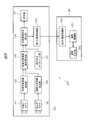
- FIG. 1 is a block diagram showing an example of the configuration of the work support apparatus according to Embodiment 1 of the present invention.
- the work support device 150 includes a visible light camera 101 as a visible light imaging unit, a far infrared camera 103 as a thermal image imaging unit, a work target region extraction unit 102, a temperature distribution image generation unit 104, A work target area temperature calculation unit 105, a work progress status determination unit 106, and a display unit 107 are provided.
- the visible light camera 101 is connected to the work target area extraction unit 102.
- the work target area extraction unit 102 is connected to the visible light camera 101 and the work target area temperature calculation unit 105.
- the far-infrared camera 103 is connected to the temperature distribution image generation unit 104.
- the temperature distribution image generation unit 104 is connected to the far-infrared camera 103 and the work target region temperature calculation unit 105.
- the work target area temperature calculation unit 105 is connected to the work target area extraction unit 102, the temperature distribution image generation unit 104, and the work progress status determination unit 106.
- the work progress status determination unit 106 is connected to the work target region temperature calculation unit 105 and the display unit 107.
- the visible light camera 101 captures, for example, a visible light image of the work target area and its surrounding area, and outputs the captured visible light image to the work target area extraction unit 102.
- the work area extraction unit 102 extracts a work area from the visible light image.
- the work target area extraction unit 102 stores data related to the work content, and extracts the work target area from the visible light image by comparing the data specifying the work target area with the visible light image.
- the work target area extraction unit 102 specifies the shape and size of an object in the visible light image by performing image processing on the visible light image, and refers to the shape and size of the work target registered in advance. To do.
- the work target area extraction unit 102 extracts a work target area for temperature measurement from the captured visible light image.
- the far-infrared camera 103 captures a thermal image of the work target area and its surroundings, and outputs the captured thermal image to the temperature distribution image generation unit 104.
- the visible light camera 101 and the far-infrared camera 103 are preferably adjusted so that, for example, the imaging area of the far-infrared camera 103 and the imaging area of the visible-light camera 101 are substantially equal.
- the temperature distribution image generation unit 104 generates a temperature distribution image from the thermal image captured by the far infrared camera 103.
- the temperature distribution image generation unit 104 converts a thermal image captured by the far-infrared camera 103 into a visible light image and generates a temperature distribution image.
- different colors are displayed for each temperature. For example, in the temperature distribution image, the low temperature is displayed in blue, the medium temperature is displayed in yellow, and the high temperature is displayed in red.
- the work target area temperature calculation unit 105 calculates the work temperature of the work target area extracted by the work target area extraction unit 102 based on the temperature distribution image generated by the visible light image and the temperature distribution image generation unit 104. For example, the work target region temperature calculation unit 105 compares the visible light image and the temperature distribution image with respect to the work target region that is the target of temperature measurement extracted by the work target region extraction unit 102, and performs work on the temperature distribution image. The target area is specified, and the temperature of the work target area is calculated.
- the work progress status determination unit 106 determines the work progress status based on the work temperature of the work target area calculated by the work target area temperature calculation unit 105. For example, the work progress status determination unit 106 determines the work progress status based on the work temperature of the work target area and the work time for the work target area. Specifically, the work progress situation determination unit 106 starts measuring the work time when the work target area reaches or exceeds a predetermined work temperature set in advance, and based on the work time and the predetermined work time set in advance. To determine the work progress.
- the work progress determination unit 106 includes a data storage unit (not shown).
- the data storage unit displays the work content, a predetermined work temperature for each work target area, a predetermined work time, and the display unit 107.
- Various data related to images and the like, a control program related to control of each unit constituting the work support apparatus 150, such as the work progress determination unit 106, and the like may be stored.
- the data storage unit may be provided in other components constituting the work support apparatus 150 or may be provided independently.
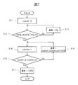
- FIG. 2 is a flowchart showing an example of the operation of the work progress situation determination unit in the first embodiment of the present invention.
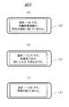
- FIG. 3 is a diagram illustrating an example of an image displayed on the display unit in accordance with the work progress status.
- the operation of the work progress determination unit will be described by taking the work of heating the work target area as an example.
- the heating operation is performed by, for example, a work device (not shown).
- the reason why such a process is provided is to reset the work time measured in the work performed before this process.
- the work progress status determination unit 106 resets the work time, the process progresses to step S12.
- step S12 the work progress determination unit 106 compares the work temperature (Temp_target) of the work target area calculated by the work target area temperature calculation unit 105 with a predetermined work temperature (Temp_set) set in advance.
- the work progress situation determination unit 106 reads a predetermined work temperature (Temp_set) corresponding to the work content from, for example, a data storage unit (not shown).
- the work progress determination unit 106 determines that the work temperature of the work target area is lower than the predetermined work temperature, that is, the work temperature of the work target area does not reach the predetermined work temperature (Temp_target ⁇ In Temp_set), it is determined that the work progress status is 0%, and the process proceeds to step S13 (the determination result is No).
- step S ⁇ b> 13 the work progress determination unit 106 reads data related to an image indicating that the progress rate is 0% on the display unit 107 from a data storage unit (not shown), and outputs the read data to the display unit 107.
- the display unit 107 displays an image related to the determination result as shown in FIG. 3A based on the data output from the work progress situation determination unit 106, for example.
- the display unit 107 may display, for example, an image indicating the status of the work target area together with the determination result.
- the work progress determination unit 106 proceeds to step S12 again. Accordingly, the work progress situation determination unit 106 repeatedly executes these steps S12 to S13 until the work temperature of the work target area reaches a predetermined work temperature.
- step S12 the work progress situation determination unit 106 determines that the work temperature of the work target area is equal to or higher than the predetermined work temperature, that is, the work temperature of the work target area reaches the predetermined work temperature (Temp_target ⁇ In (Temp_set), the process proceeds to step S14 (the determination result is Yes).
- step S14 the work progress status determination unit 106 starts measuring a work time (counter) (counter ++).
- the work time may be counted up at a predetermined cycle, and the work time may be measured by replacing the count number with the work time, or the work time may be measured directly. You may make it measure time.
- a predetermined work time to be described later is also expressed by the count number.
- step S15 the work progress determination unit 106 compares the work time (counter) with a predetermined work time (counter_set) required for the work.
- the work progress determination unit 106 reads a predetermined work time (counter_set) corresponding to the work content from, for example, a data storage unit (not shown). As a result of comparing these times, if the work time is less than the predetermined work time (counter ⁇ counter_set), the work progress status determination unit 106 proceeds to step S16 (the determination result is No).
- the display unit 107 may display an image indicating information such as the remaining time until the completion of work, for example, as shown in FIG.
- the work progress situation determination unit 106 proceeds to step S14 again and executes the operations according to steps S14 and S15. That is, since the work progress status is less than 100% here, the work progress status determination unit 106 returns to step S14 again. Therefore, the work progress status determination unit 106 repeatedly executes these steps S14 to S16 until the work time reaches a predetermined work time and the work progress status reaches 100%.
- step S15 the work progress situation determination unit 106 compares the time, and if the work time is equal to or longer than the predetermined work time (counter ⁇ counter_set), the work on the work target area is completed. It determines with having completed and transfers to process S17 (determination result is Yes).
- step S ⁇ b> 17 the work progress situation determination unit 106 reads data related to an image indicating that the work is completed from a data storage unit (not shown), and outputs the read data to the display unit 107. Based on the data output from the work progress determination unit 106, the display unit 107 displays, for example, an image related to the determination result as shown in FIG. 3C, for example, an image indicating that the work progress is 100%. To do. In addition, the display unit 107 may display an image indicating that the work is completed, for example, as shown in FIG. When an image indicating that the work on the work target area is completed is displayed on the display unit 107, the work progress status determination unit 106 ends a series of operations related to the determination of the work progress status.
- the display unit 107 accepts input of data related to the image related to the determination result of the work progress status output from the work progress status determination unit 106, and displays various images based on the input data.
- various display panels such as a liquid crystal panel, an organic EL (electroluminescence) panel, and so-called electronic paper are used.
- the work target region extraction unit 102, the temperature distribution image generation unit 104, the work target region temperature calculation unit 105, and the work progress status determination unit 106 may be realized by different hardware or by software. Good. Further, these components may be realized together in one hardware, or may be realized together in one software. Moreover, these components may be realized in other components.
- FIG. 4 is a diagram showing an example of the work support apparatus according to Embodiment 1 of the present invention.
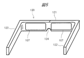
- FIG. 5 is a diagram showing an example of a form of the head mounted display according to Embodiment 1 of the present invention.
- the display unit 107 of the work support device 150 is provided in the head mounted display 120 as shown in FIGS. 4 and 5, for example.
- a visible light camera 101, a far infrared camera 103, and the like are attached to the head mounted display 120.
- the visible light camera 101 and the far-infrared camera 103 may be attached in the vicinity of the display unit 107 as shown in FIG. 4, or may be attached to a work helmet or the like worn by the worker 190, for example.
- the work target area extraction unit 102, the temperature distribution image generation unit 104, the work target area temperature calculation unit 105, the work progress status determination unit 106, and the like are not displayed.
- the included control unit may be provided separately, and the control unit may be connected to the visible light camera 101, the far infrared camera 103, the display unit 107, and the like.
- the head mounted display 120 is a glasses-type display device worn by the operator 190 on the head. As shown in FIGS. 4 and 5, the head mounted display 120 includes a frame 121, temples 122 and 123, a pad 124, a display unit 107, and the like.
- the frame 121 is a member that supports the display unit 107.
- the temple 122 is connected to the right end of the frame 121 when viewed from the operator 190 when attached, and extends toward the rear of the operator 190.
- the temple 123 is connected to the left end of the frame 121 when viewed from the operator 190 when attached, and extends toward the rear of the operator 190.
- the pad 124 is placed on the nose 191 of the worker 190, and the temples 122 and 123 come into contact with the side of the worker 190 and the ear (not shown).
- the head mounted display 120 is supported on the head of the operator 190.
- the display unit 107 is arranged in front of the worker 190.
- the worker 190 can acquire information necessary for the work by looking at the image displayed on the display unit 107 without using one or both hands.
- the display unit 107 may be provided only on one of the left and right sides.
- the display unit 107 may be configured to be attached to, for example, an eyeglass lens used by the operator 190, or may be configured to be attached to, for example, work goggles or an eyeglass lens. It may be what was done.
- the work progress determination unit 106 determines the work progress based on the visible light image captured by the visible light camera 101 and the thermal image captured by the far infrared camera 103, and The determination result is displayed on the display unit 107.
- the work target region temperature calculation unit 105 performs the work from the work target region extracted by the work target region extraction unit 102 and the temperature distribution image generated by the temperature distribution image generation unit 104.
- the work temperature of the target area is calculated, and the work progress determination unit 106 determines the work progress based on the calculated work temperature and the work time for the work target area, and the determination result of the work progress is displayed on the display unit 107. Is displayed.
- the work progress situation determination unit 106 determines the work time when the work target area reaches a predetermined work temperature or higher. Measurement is started, and the work progress status is determined based on the work time and a predetermined work time set in advance until the work is completed.
- the display unit 107 displays the result of the determination of the work progress status, the image of the status of the work target area as shown in FIGS. 3A to 3C, and the completion of the work.
- An image such as the remaining time, an image indicating that the work has been completed, and the like are displayed together with the determination result of the work progress status.
- the worker 190 can acquire additional information related to the work target area, and thus can grasp the work progress status in more detail.
- the work target area extraction unit 102 extracts a work target area from the visible light image captured by the visible light camera 101, and the temperature distribution image generation unit 104 performs the far infrared camera 103.
- a temperature distribution image is generated from the thermal image captured in step, and the work target area temperature calculation unit 105 calculates the work temperature of the work target area based on the work target area and the temperature distribution image.
- the visible light camera 101 and the far-infrared camera 103 are adjusted so that the imaging region of the far-infrared camera 103 and the imaging region of the visible light camera 101 are substantially equal. Yes.
- the visible light image and the temperature distribution image can be easily compared, and the working temperature of the work target area can be calculated more accurately. Thereby, the accuracy of work can be improved.
- the display unit 107 is provided in the head mounted display 120. According to this configuration, the display unit 107 is placed in front of the eyes of the worker 190 by mounting the head mounted display 120 on the head, so that the determination result of the work progress status can be acquired without using both hands. .
- the work progress status determination unit 106 determines the work progress status for the next work after one work is completed. For example, when the work progress status of one work reaches 100%, the work content of the next step is displayed on the display unit 107, and the work progress status determination unit 106 determines the work progress status of the next work. Start.
- FIG. 6 is a flowchart showing an example of the operation of the work progress status determination unit in the second embodiment of the present invention.
- FIG. 7 is a diagram illustrating an example of an image displayed on the display unit in accordance with the work progress status.
- step S17 an image indicating that the work on the work target area has been completed is displayed on the display unit 107, for example, an image indicating that the work progress has reached 100% as shown in FIG. Then, the work progress situation determination unit 106 proceeds to step S28 shown in FIG.
- step S28 the work progress situation determination unit 106 determines whether or not there is a next work. For example, the work progress status determination unit 106 reads out data related to the work content from a data storage unit (not shown) and compares the data with the completed work content to determine the presence or absence of the next work. If the work progress status determination unit 106 determines that there is a next work, the process progresses to step S29 (the determination result is No).
- step S ⁇ b> 29 the work progress situation determination unit 106 reads data related to an image indicating that the next work is to be transferred from, for example, a data storage unit (not shown), and outputs the read data to the display unit 107. Based on the data output from the work progress status determination unit 106, the display unit 107 displays an image indicating that the next work is to be performed, for example, as illustrated in FIG. In addition to this, the display unit 107 displays, for example, an image indicating the specific content of the next operation, as shown in FIG. 7A, together with an image indicating that the next operation is to be performed. You may make it do.
- the work progress determination unit 106 reads a predetermined work temperature (Temp_set) and a predetermined work time (counter_set) corresponding to the next work content from, for example, a data storage unit (not shown), and reads the predetermined work temperature and the predetermined work temperature. Update work time data. When these operations are executed, the work progress determination unit 106 proceeds to step S11 and determines the work progress regarding the next work content.
- step S28 when the work progress determination unit 106 determines that there is no next work, the process progresses to step S30 (the determination result is Yes).
- step S ⁇ b> 30 the work progress situation determination unit 106 reads data related to an image indicating that all work has been completed, for example, from a data storage unit (not shown), and outputs the read data to the display unit 107.
- the display unit 107 displays, based on the data output from the work progress status determination unit 106, an image indicating that all work has been completed, as shown in FIG. 7B, for example.
- the display unit 107 may display specific instruction contents to the worker 190 after the work is completed, for example, as shown in FIG.
- the work progress status determination unit 106 ends a series of operations related to determination of the work progress status.
- the work progress determination unit 106 automatically determines the work progress for the next work, and determines the work progress for the next work. It is displayed on the display unit 107. According to this configuration, even when a plurality of operations are continuously performed, the determination result regarding the progress of the operation is automatically displayed. Therefore, the determination of the operation progress is performed for each operation. Can be omitted, and the working efficiency can be greatly improved.
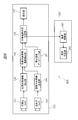
- FIG. 8 is a block diagram showing an example of the configuration of the work support system according to Embodiment 3 of the present invention.
- the work support system 200 includes a work support device 250 and a work device 260.
- the work support apparatus 250 includes a visible light camera 101 as a visible light imaging unit, a far infrared camera 103 as a thermal image imaging unit, a work target region extraction unit 102, a temperature distribution image generation unit 104, and a work target region temperature calculation unit 105.
- the work equipment 260 includes a temperature control unit 261 and a temperature generation unit 262.
- the appropriate temperature database unit 251 of the work support apparatus 250 is connected to the work progress determination unit 106.
- the work progress status determination unit 106 is connected to the appropriate temperature database unit 251 and the temperature control unit 261 of the work device 260.
- the work progress determination unit 106 and the temperature control unit 261 are connected by wiring such as a cable, for example. Thereby, the work support apparatus 250 and the work equipment 260 are connected.
- the temperature control unit 261 is connected to the work progress status determination unit 106 and the temperature generation unit 262.
- the visible light camera 101, the far-infrared camera 103 as a thermal image capturing unit, the work target region extraction unit 102, the temperature distribution image generation unit 104, the work target region temperature calculation unit 105, and the display unit 107 are implemented. Since it is described in the first embodiment, detailed description is omitted.
- the appropriate temperature database unit 251 holds information related to the appropriate temperature of the work target area during work.
- the appropriate temperature database unit 251 may hold information related to appropriate temperatures for a plurality of operations, or may hold information related to appropriate temperatures updated for each operation.
- the work progress status determination unit 106 determines the work progress status as described above, calculates the difference between the work temperature of the work target area and the appropriate temperature read from the appropriate temperature database unit 251, and calculates the difference as difference temperature information. Is output to the temperature control unit 261 of the work equipment 260.
- the temperature control unit 261 performs temperature control based on the differential temperature information output from the work progress situation determination unit 106. For example, when the temperature control unit 261 determines that the work temperature of the work target area is lower than the appropriate temperature based on the difference temperature information, the temperature control unit 261 performs control to increase the work temperature. Specifically, the temperature control unit 261 performs control to increase the temperature of the temperature generation unit 262 with respect to the temperature generation unit 262. Specifically, the temperature control unit 261 increases the amount of current supplied to a temperature adjustment member such as a heater (not shown) that constitutes the temperature generation unit 262, for example. As a result, the working temperature for the work target area increases. At that time, the work progress situation determination unit 106 may display an image indicating that the temperature of the work device 260 is increased on the display unit 107.
- a temperature adjustment member such as a heater (not shown) that constitutes the temperature generation unit 262
- the temperature control unit 261 determines that the work temperature in the work target area is higher than the appropriate temperature based on the difference temperature information, the temperature control unit 261 performs control to suppress the increase in the work temperature. Specifically, the temperature control unit 261 performs control to suppress the temperature increase of the temperature generation unit 262 with respect to the temperature generation unit 262. Specifically, the temperature control unit 261 decreases the amount of current supplied to, for example, a heater. Thereby, the raise of working temperature is suppressed. At that time, the work progress status determination unit 106 may display an image indicating that the temperature of the work device 260 is prevented from rising on the display unit 107.
- the temperature control unit 261 may perform control to reduce the work temperature. Specifically, the temperature control unit 261 performs control to lower the temperature of the temperature generation unit 262 with respect to the temperature generation unit 262. Specifically, the temperature control unit 261 further reduces the amount of current supplied to, for example, a heater. Alternatively, the temperature control unit 261 temporarily stops the current supply to the heater or the like. Thereby, working temperature is reduced. At that time, the work progress situation determination unit 106 may display an image indicating that the temperature of the work device 260 is decreased on the display unit 107.
- the temperature controller 261 may be realized by hardware or software.
- the temperature control unit 261 may be realized in hardware or software of other components.
- the temperature control unit 261 controls, for example, the amount of current supplied to the temperature generation unit 262 to control the temperature generation unit 262.
- the temperature is controlled.
- the work temperature in the work target area can be controlled while the work support device 250 and the work device 260 are linked, so that work can be performed more efficiently.
- work can be improved.
- the work progress situation determination unit 106 displays an image related to the temperature control information for the work device 260 on the display unit 107. According to this configuration, the worker 190 can know not only the work progress status but also the status of the work equipment 260, and thus can obtain more detailed information regarding the work.
- FIG. 9 is a block diagram showing an example of the configuration of the work support system according to Embodiment 4 of the present invention.
- the work support system 200 includes a work support device 350 and a work device 360.
- the work support apparatus 350 includes the components of the work support apparatus 250 illustrated in FIG. 8 and a first communication processing unit 352.
- the work device 360 includes the components of the work device 260 shown in FIG. 8 and a second communication processing unit 363.
- the work progress determination unit 106 outputs the difference temperature information to the first communication processing unit 352.
- the first communication processing unit 352 is connected to the work progress status determination unit 106.
- the first communication processing unit 352 is an external interface that connects the work support apparatus 350 and the work device 360, and is connected to the second communication processing unit 363 of the work device 360 via a wireless network. .
- the first communication processing unit 352 and the second communication processing unit 363 can exchange data with each other via a wireless network.
- the first communication processing unit 352 transmits the differential temperature information output from the work progress situation determination unit 106 to the second communication processing unit 363.
- the second communication processing unit 363 is connected to the temperature control unit 261.
- the second communication processing unit 363 is an external interface that connects the work support device 350 and the work device 360, and is connected to the first communication processing unit 352 of the work support device 350 via a wireless network. Yes.
- the second communication processing unit 363 outputs the difference temperature information received from the first communication processing unit 352 to the temperature control unit 261.
- the temperature control unit 261 performs the temperature control as described above based on the differential temperature information output from the second communication processing unit 363, for example.
- the first communication processing unit 352 and the second communication processing unit 363 are connected via a wireless network, and the first communication processing unit 352 and the second communication processing unit 363 are connected.
- Various data such as differential temperature information is transmitted and received between them.
- the temperature control of the work device 360 can be performed based on the differential temperature information.
- the work equipment 360 can be easily handled and the work can be easily performed.
- step S12 when the work temperature of the work target area exceeds the predetermined work temperature, that is, the work temperature of the work target area does not reach the predetermined work temperature ( For Temp_target> Temp_set, the work progress status determination unit 106 determines that the work progress status is 0%, and proceeds to step S13 (the determination result is No).
- step S14 the process proceeds to step S14 ( The determination result is Yes).
- a process for determining the work temperature is not provided.
- a step of determining the working temperature during the measurement may be provided.
- the working time measurement may be temporarily stopped, and the remaining working time may be measured after the working temperature is recovered. According to such a configuration, work accuracy can be further improved.
Landscapes
- Engineering & Computer Science (AREA)
- Multimedia (AREA)
- Physics & Mathematics (AREA)
- General Physics & Mathematics (AREA)
- Signal Processing (AREA)
- Automation & Control Theory (AREA)
- Human Computer Interaction (AREA)
- Quality & Reliability (AREA)
- General Engineering & Computer Science (AREA)
- Theoretical Computer Science (AREA)
- Manufacturing & Machinery (AREA)
- Computer Vision & Pattern Recognition (AREA)
- Spectroscopy & Molecular Physics (AREA)
- General Factory Administration (AREA)
- Radiation Pyrometers (AREA)
Abstract
可視光画像を撮像する可視光カメラ(可視光画像撮像部)と、熱画像を撮像する遠赤外カメラ(熱画像撮像部)と、可視光カメラで撮像された可視光画像及び遠赤外カメラで撮像された熱画像から作業進捗状況を判定する作業進捗状況判定部と、作業進捗状況の判定結果を表示する表示部と、を有する。
Description
本発明は、作業支援装置及び作業支援システムに関するものである。
近年、装置や設備の保守作業において携帯情報端末を用いた作業効率化が図られている。このような携帯情報端末によれば、作業員はあらかじめ作業情報を携帯情報端末に取り込んでおき、作業中は作業情報を画面に表示させることで必要な情報を得ることが可能である。
しかしながら、携帯情報端末を手に持って画面を見ながら作業をする必要があり、このような状態では、作業が煩雑となり、却って作業効率が低下する場合があった。そこで、携帯情報端末を手に取ることなく作業者に情報を提供することができる作業支援装置が提案されている。
例えば、特許文献1には、ヘッドマウントディスプレイと呼ばれる頭部搭載型の表示部を使用し、作業に関する情報を作業者に提示する作業支援装置が開示されている。このようなヘッドマウントディスプレイを用いることで、作業者は、携帯情報端末を手に持つ必要がなくなり、効率的に作業を実施することができる。
また、特許文献1には、可視光撮像部及び赤外線撮像部が設けられ、可視光撮像部で撮像された可視光線像及び赤外線撮像部で撮像された赤外線像がヘッドマウントディスプレイに表示され、可視光線像から検出された部品と、赤外線像から取得された温度分布画像とから、温度が異常である部品を検知し、ヘッドマウントディスプレイを通じて作業者に異常が通知される作業支援装置が開示されている。
ところで、特許文献1では、異常な温度となる部品を検知する方法については開示されているが、作業の進捗状況を作業者へ通知する方法については考慮されていなかった。このため、作業支援装置を使用していても、作業者は、作業の進捗状況を把握することが困難な場合があった。
そこで、本発明の目的は、作業の進捗状況を作業者に知らせることができる作業支援装置及び作業支援システムを提供することにある。
本願において開示される発明のうち、代表的なものの概要を簡単に説明すれば、以下のとおりである。
本発明の代表的な実施の形態による作業支援装置は、可視光画像を撮像する可視光画像撮像部と、熱画像を撮像する熱画像撮像部と、可視光画像撮像部で撮像された可視光画像及び熱画像撮像部で撮像された熱画像から作業進捗状況を判定する作業進捗状況判定部と、作業進捗状況の判定結果を表示する表示部と、を有する。
本願において開示される発明のうち、代表的なものによって得られる効果を簡単に説明すれば以下のとおりである。
すなわち、本発明の代表的な実施の形態によれば、作業の進捗状況を作業者に知らせることができる作業支援装置を提供することができる。
以下、本発明の実施の形態を図面に基づいて詳細に説明する。なお、実施の形態を説明するための全ての図において、同一の機能を有する部材には同一の符号を付し、その繰り返しの説明は省略する。また、図面をわかりやすくするために平面図であってもハッチングを付す場合がある。
さらに、以下の実施の形態では便宜上その必要があるときは、複数のセクションまたは実施の形態に分割して説明するが、特に明示した場合を除き、それらはお互いに無関係なものではなく、一方は他方の一部または全部の変形例、詳細、補足説明などの関係にある。
また、以下の実施の形態において、要素の数など(個数、数値、量、範囲などを含む)に言及する場合、特に明示した場合および原理的に明らかに特定の数に限定される場合などを除き、その特定の数に限定されるものではなく、特定の数以上でも以下でも良いものとする。
また、以下の実施の形態において、その構成要素(要素ステップ等も含む)は、特に明示した場合および原理的に明らかに必須であると考えられる場合等を除き、必ずしも必須のものではないことは言うまでもない。
また、以下の実施の形態において、構成要素等について、「Aからなる」、「Aよりなる」、「Aを有する」、「Aを含む」と言うときは、特にその要素のみである旨明示した場合等を除き、それ以外の要素を排除するものでないことは言うまでもない。同様に、以下の実施の形態において、構成要素等の形状、位置関係等に言及するときは、特に明示した場合および原理的に明らかにそうでないと考えられる場合等を除き、実質的にその形状等に近似または類似するもの等を含むものとする。このことは、上記数値および範囲等についても同様である。
(実施の形態1)
図1は、本発明の実施の形態1に係る作業支援装置の構成の一例を示すブロック図である。作業支援装置150は、図1に示すように、可視光撮像部としての可視光カメラ101、熱画像撮像部としての遠赤外カメラ103、作業対象領域抽出部102、温度分布画像生成部104、作業対象領域温度算出部105、作業進捗状況判定部106、表示部107を備えている。
図1は、本発明の実施の形態1に係る作業支援装置の構成の一例を示すブロック図である。作業支援装置150は、図1に示すように、可視光撮像部としての可視光カメラ101、熱画像撮像部としての遠赤外カメラ103、作業対象領域抽出部102、温度分布画像生成部104、作業対象領域温度算出部105、作業進捗状況判定部106、表示部107を備えている。
可視光カメラ101は、作業対象領域抽出部102と接続されている。作業対象領域抽出部102は、可視光カメラ101及び作業対象領域温度算出部105と接続されている。遠赤外カメラ103は、温度分布画像生成部104と接続されている。温度分布画像生成部104は、遠赤外カメラ103及び作業対象領域温度算出部105と接続されている。作業対象領域温度算出部105は、作業対象領域抽出部102、温度分布画像生成部104及び作業進捗状況判定部106と接続されている。作業進捗状況判定部106は、作業対象領域温度算出部105及び表示部107と接続されている。
可視光カメラ101は、例えば、作業対象領域やその周辺領域の可視光画像を撮像し、撮像した可視光画像を作業対象領域抽出部102に出力する。
作業対象領域抽出部102は、可視光画像から作業対象領域を抽出する。例えば、作業対象領域抽出部102には、作業内容に関するデータが格納され、作業対象領域を特定するデータと可視光画像とを比較することにより、可視光画像から作業対象領域を抽出する。詳しくは、作業対象領域抽出部102は、可視光画像を画像処理することにより可視光画像中の物体の形状や大きさを特定し、事前に登録されている作業対象物の形状や大きさと参照する。このように、作業対象領域抽出部102は、撮像された可視光画像の中から温度測定を行う作業対象領域を抽出する。
遠赤外カメラ103は、例えば、作業対象領域やその周辺の熱画像を撮像し、撮像した熱画像を温度分布画像生成部104に出力する。
可視光カメラ101及び遠赤外カメラ103は、例えば、遠赤外カメラ103の撮像領域と可視光カメラ101の撮像領域とがほぼ同等となるように、調整されていることが好ましい。
温度分布画像生成部104は、遠赤外カメラ103で撮像された熱画像から温度分布画像を生成する。例えば、温度分布画像生成部104は、遠赤外カメラ103で撮像された熱画像を可視光画像に変換して温度分布画像を生成する。温度分布画像では、温度ごとに異なる色が表示されている。例えば、温度分布画像では、低温が青色で表示され、中温が黄色で表示され、高温が赤色で表示されている。
作業対象領域温度算出部105は、可視光画像及び温度分布画像生成部104において生成された温度分布画像に基づいて作業対象領域抽出部102で抽出された作業対象領域の作業温度を算出する。例えば、作業対象領域温度算出部105は、作業対象領域抽出部102で抽出された温度測定の対象となる作業対象領域について、可視光画像と温度分布画像とを比較することにより温度分布画像における作業対象領域を特定し、作業対象領域の温度を算出する。
作業進捗状況判定部106は、作業対象領域温度算出部105で算出された作業対象領域の作業温度に基づいて作業進捗状況を判定する。例えば、作業進捗状況判定部106は、作業対象領域の作業温度及び作業対象領域に対する作業時間に基づいて作業進捗状況を判定する。具体的には、作業進捗状況判定部106は、作業対象領域が予め設定された所定の作業温度以上に達したら作業時間の計測を開始し、作業時間及び予め設定された所定の作業時間に基づいて作業進捗状況を判定する。
作業進捗状況判定部106には、例えば、図示しないデータ格納部が設けられ、データ格納部には、作業内容、作業対象領域ごとの所定の作業温度、所定の作業時間、表示部107に表示させる画像等に関する各種データや、作業進捗状況判定部106等、作業支援装置150を構成する各部の制御に係る制御プログラム等が格納されるようにしてもよい。また、データ格納部は、作業支援装置150を構成するその他の構成要素に設けられるようにしてもよいし、独立して設けられてもよい。
ここで、作業進捗状況判定部106において作業進捗状況の判定に係る一連の動作について詳しく説明する。図2は、本発明の実施の形態1における作業進捗状況判定部の動作の一例を示すフローチャート図である。図3は、作業進捗状況に応じて表示部に表示される画像の一例を示す図である。
以下では、作業対象領域に対して加熱する作業を例に挙げて、作業進捗状況判定部の動作を説明する。また、加熱作業は、例えば、図示しない作業機器により実施される。
まず、工程S11では、作業進捗状況判定部106は、作業時間を「0」にセットする(counter=0)。このような工程を設けているのは、これ以前に実施した作業において計測した作業時間をリセットするためである。作業進捗状況判定部106は、作業時間をリセットすると、工程S12に移行する。
工程S12では、作業進捗状況判定部106は、作業対象領域温度算出部105で算出された作業対象領域の作業温度(Temp_target)と、予め設定された所定の作業温度(Temp_set)とを比較する。作業進捗状況判定部106は、作業内容に対応する所定の作業温度(Temp_set)を、例えば図示しないデータ格納部から読み出す。作業進捗状況判定部106は、これらの温度を比較した結果、作業対象領域の作業温度が所定の作業温度未満、すなわち、作業対象領域の作業温度が所定の作業温度に達していない場合(Temp_target<Temp_set)には、作業進捗状況が0%であると判定し、工程S13に移行する(判定結果がNo)。
工程S13では、作業進捗状況判定部106は、表示部107に進捗率が0%であることを示す画像に関するデータを、図示しないデータ格納部から読み出し、読み出したデータを表示部107に出力する。表示部107は、作業進捗状況判定部106から出力されたデータに基づいて、例えば図3(a)に示すような判定結果に関する画像を表示する。また、表示部107は、これ以外にも、図3(a)に示すように、例えば作業対象領域の状況等について示す画像を判定結果と合わせて表示するようにしてもよい。表示部107にこのような画像が表示されると、作業進捗状況判定部106は再び工程S12に移行する。したがって、作業進捗状況判定部106は、作業対象領域の作業温度が、所定の作業温度に達するまで、これらの工程S12~S13を繰り返し実行する。
これに対して、工程S12において、作業進捗状況判定部106は、作業対象領域の作業温度が所定の作業温度以上、すなわち、作業対象領域の作業温度が所定の作業温度に達した場合(Temp_target≧Temp_set)には、工程S14に移行する(判定結果がYes)。
工程S14では、作業進捗状況判定部106は、作業時間(counter)の計測(counter++)を開始する。作業時間の計測方法としては、例えば、所定の周期で作業時間をカウントアップし、そのカウント数を作業時間に置き換えることにより作業時間を計測するようにしてもよいし、時間を直接計ることにより作業時間を計測するようにしてもよい。なお、カウントにより作業時間を計測する場合には、後述する所定の作業時間もカウント数で表されることとなる。作業進捗状況判定部106は、作業時間の計測を開始すると、工程S15に移行する。
工程S15では、作業進捗状況判定部106は、作業時間(counter)と作業に要する所定の作業時間(counter_set)とを比較する。作業進捗状況判定部106は、作業内容に対応する所定の作業時間(counter_set)を、例えば図示しないデータ格納部から読み出す。作業進捗状況判定部106は、これらの時間を比較した結果、作業時間が所定の作業時間未満である場合(counter<counter_set)には、工程S16に移行する(判定結果がNo)。
工程S16では、作業進捗状況判定部106は、作業時間(counter)及び所定の作業時間(counter_set)に基づいて作業進捗状況を判定する。具体的には、作業進捗状況判定部106は、次の式「作業進捗=counter/(counter_set)*100(%)」を用いて作業進捗状況を示す数値を具体的に算出する。また、作業進捗状況判定部106は、作業進捗状況を算出すると、作業中であることを示す画像に関するデータを図示しないデータ格納部から読み出し、読み出したデータを表示部107に出力する。表示部107は、作業進捗状況判定部106から出力されたデータに基づいて、例えば図3(b)に示すような判定結果に関する画像、例えば作業進捗状況の具体的な数値を表示する。また、表示部107は、これ以外にも、例えば図3(b)に示すような、作業完了までの残り時間等の情報を示す画像を判定結果と合わせて表示するようにしてもよい。表示部107にこのような画像が表示されると、作業進捗状況判定部106は、再び工程S14に移行し、工程S14、S15に係る動作を実行する。すなわち、ここでは作業進捗状況が100%未満であるため、作業進捗状況判定部106は、再び工程S14に戻る。したがって、作業進捗状況判定部106は、作業時間が所定の作業時間に達し作業進捗状況が100%となるまで、これらの工程S14~S16を繰り返し実行する。
これに対して、工程S15において、作業進捗状況判定部106は、これらの時間を比較した結果、作業時間が所定の作業時間以上である場合(counter≧counter_set)には、作業対象領域に対する作業が完了したものと判定し、工程S17に移行する(判定結果がYes)。
工程S17では、作業進捗状況判定部106は、作業が完了したことを示す画像に関するデータを図示しないデータ格納部から読み出し、読み出したデータを表示部107に出力する。表示部107は、作業進捗状況判定部106から出力されたデータに基づいて、例えば図3(c)に示すような判定結果に関する画像、例えば作業進捗状況が100%であることを示す画像を表示する。また、表示部107は、これ以外にも、例えば図3(c)に示すような、作業が完了したことを示す画像を判定結果と合わせて表示するようにしてもよい。表示部107に、作業対象領域に対する作業が完了したことを示す画像が表示されると、作業進捗状況判定部106は、作業進捗状況の判定に係る一連の動作を終了する。
表示部107は、上述したように、作業進捗状況判定部106から出力された作業進捗状況の判定結果等に関する画像に関するデータ等の入力を受け付け、入力されたデータに基づいて各種画像を表示する。表示部107には、例えば、液晶パネル、有機EL(electroluminescence)パネル、いわゆる電子ペーパー等の各種表示パネルが用いられる。
作業対象領域抽出部102、温度分布画像生成部104、作業対象領域温度算出部105、作業進捗状況判定部106については、それぞれに異なるハードウェアで実現されてもよいし、ソフトウェアで実現されてもよい。また、これらの構成要素が、1つのハードウェアの中でまとめて実現されてもよいし、1つのソフトウェアの中でまとめて実現されてもよい。また、これらの構成要素が、その他の構成要素中で実現されてもよい。
ここで、作業支援装置150の形態の一例について説明する。図4は、本発明の実施の形態1に係る作業支援装置の形態の一例を示す図である。図5は、本発明の実施の形態1に係るヘッドマウントディスプレイの形態の一例を示す図である。
作業支援装置150の表示部107は、例えば図4、図5に示すように、ヘッドマウントディスプレイ120に設けられている。ヘッドマウントディスプレイ120には、例えば図4に示すように、可視光カメラ101、遠赤外カメラ103等が取り付けられている。 可視光カメラ101、遠赤外カメラ103は、図4に示すように表示部107の近傍に取り付けられてもよいし、例えば、作業者190が装着する作業用ヘルメット等に取り付けられてもよい。なお、図4には、作業対象領域抽出部102、温度分布画像生成部104、作業対象領域温度算出部105、作業進捗状況判定部106等が表示されていないが、例えば、これらの構成要素を含んだ制御ユニットが別体で設けられ、制御ユニットが可視光カメラ101、遠赤外カメラ103、表示部107等と接続されるようにしてもよい。
ヘッドマウントディスプレイ120は、作業者190が頭部に装着する眼鏡タイプの表示装置である。ヘッドマウントディスプレイ120は、図4、図5に示すように、フレーム121、テンプル122、123、パッド124、表示部107等を備えている。
フレーム121は、表示部107を支持する部材である。テンプル122は、装着された際に作業者190から見てフレーム121の右側の端部と接続され、作業者190の後方に向かって延在している。テンプル123は、装着された際に作業者190から見てフレーム121の左側の端部と接続され、作業者190の後方に向かって延在している。
ヘッドマウントディスプレイ120の装着時には、図4に示すように、パッド124が作業者190の鼻191に載置され、テンプル122、123が作業者190の側頭部及び図示しない耳と当接することにより、ヘッドマウントディスプレイ120が作業者190の頭部に支持される。そうすると、表示部107は、作業者190の眼前に配置される。作業者190は、片手または両手を使うことなく、表示部107に表示された画像を見ることで作業に必要な情報を取得することができる。
図4、図5には、ヘッドマウントディスプレイ120に2つの表示部107が実装された場合について示されているが、このような構成に限定されるものではない。例えば、表示部107が左右いずれか片方にのみ設けられてもよい。
表示部107は、例えば、作業者190が使用するメガネ用レンズに取り付けることができるように構成されたものであってもよいし、例えば作業用ゴーグルやメガネ用レンズ等に貼り付けられるように構成されたものであってもよい。
本実施の形態によれば、可視光カメラ101で撮像された可視光画像及び遠赤外カメラ103で撮像された熱画像に基づいて、作業進捗状況判定部106が、作業進捗状況を判定し、判定結果が表示部107に表示される。
この構成によれば、作業者190が表示部107に表示された作業進捗状況の判定結果を見ることが可能となるので、作業の進捗状況を作業者に知らせることができる。
また、本実施の形態によれば、作業対象領域抽出部102で抽出された作業対象領域と、温度分布画像生成部104で生成された温度分布画像とから、作業対象領域温度算出部105において作業対象領域の作業温度が算出され、作業進捗状況判定部106では、算出された作業温度及び作業対象領域に対する作業時間に基づいて作業進捗状況が判定され、作業進捗状況の判定結果が表示部107に表示される。
この構成によれば、作業温度及び作業時間により作業進捗状況が判定されるので、作業の精度を向上させることができる。
また、本実施の形態によれば、作業対象領域を加熱する作業を行う場合には、作業進捗状況判定部106は、作業対象領域が予め設定された所定の作業温度以上に達したら作業時間の計測を開始し、作業時間及び予め設定された、作業が完了するまでの所定の作業時間に基づいて作業進捗状況を判定する。
この構成によれば、作業対象領域の温度が所定の作業温度よりも低い場合における作業については作業時間がカウントされなくなるので、作業の精度をより一層向上させることができる。
また、本実施の形態によれば、表示部107には、作業進捗状況の判定結果とともに、図3(a)~(c)に示すような、作業対象領域の状況等について画像、作業完了までの残り時間等の画像、作業が完了したことを示す画像などが、作業進捗状況の判定結果と合わせて表示される。この構成によれば、作業者190は、作業対象領域に関する付加的情報を取得することができるので、作業進捗状況をより詳細に把握することができる。
また、本実施の形態によれば、作業対象領域抽出部102が、可視光カメラ101で撮像された可視光画像から作業対象領域を抽出し、温度分布画像生成部104が、遠赤外カメラ103で撮像された熱画像から温度分布画像を生成し、作業対象領域温度算出部105が、作業対象領域及び温度分布画像に基づいて作業対象領域の作業温度を算出する。この構成によれば、作業対象領域の温度が正確に算出されるので、作業の精度を向上させることができる。
また、本実施の形態によれば、可視光カメラ101及び遠赤外カメラ103は、遠赤外カメラ103の撮像領域と可視光カメラ101の撮像領域とがほぼ同等となるように、調整されている。この構成によれば、可視光画像と温度分布画像との比較が容易となり、作業対象領域の作業温度をより正確に算出することができる。また、これにより、作業の精度を向上させることができる。
また、本実施の形態によれば、表示部107は、ヘッドマウントディスプレイ120に設けられている。この構成によれば、ヘッドマウントディスプレイ120を頭部に装着することにより表示部107が作業者190の眼前に配置されるので、両手を使うことなく作業進捗状況の判定結果を取得することができる。
(実施の形態2)
次に、本発明の実施の形態2について説明する。本実施の形態に係る作業支援装置では、複数の作業を実施する場合には、作業進捗状況判定部106は、1つの作業が完了した後、次の作業についての作業進捗状況を判定する。例えば、1つの作業について作業進捗状況が100%に達したら、表示部107には次のステップの作業内容が表示され、作業進捗状況判定部106は、次の作業についての作業進捗状況の判定を開始する。
次に、本発明の実施の形態2について説明する。本実施の形態に係る作業支援装置では、複数の作業を実施する場合には、作業進捗状況判定部106は、1つの作業が完了した後、次の作業についての作業進捗状況を判定する。例えば、1つの作業について作業進捗状況が100%に達したら、表示部107には次のステップの作業内容が表示され、作業進捗状況判定部106は、次の作業についての作業進捗状況の判定を開始する。
図6は、本発明の実施の形態2における作業進捗状況判定部の動作の一例を示すフローチャート図である。図7は、作業進捗状況に応じて表示部に表示される画像の一例を示す図である。
このうち、工程S11~S17における作業進捗状況判定部106の動作については、実施の形態1における動作と同一であるため、詳細な説明を省略する。
工程S17において、表示部107に作業対象領域に対する作業が完了したことを示す画像、例えば図3(c)に示すような、作業進捗状況が100%に達したことを示す画像等が表示されると、作業進捗状況判定部106は、図6に示す工程S28に移行する。工程S28では、作業進捗状況判定部106は、次の作業の有無を判定する。作業進捗状況判定部106は、例えば、図示しないデータ格納部から作業内容に関するデータを読み出して、完了した作業内容と比較することにより、次の作業の有無を判定する。作業進捗状況判定部106は、次の作業があると判断した場合には、工程S29に移行する(判定結果がNo)。
工程S29では、作業進捗状況判定部106は、次の作業に移行することを示す画像に関するデータを、例えば図示しないデータ格納部から読み出し、読み出したデータを表示部107に出力する。表示部107は、作業進捗状況判定部106から出力されたデータに基づいて、例えば図7(a)に示すような、次の作業に移行することを示す画像を表示する。また、表示部107は、これ以外にも、例えば図7(a)に示すような、次の作業の具体的内容を示す画像等を、次の作業に移行することを示す画像と合わせて表示するようにしてもよい。また、作業進捗状況判定部106は、次の作業内容に対応する所定の作業温度(Temp_set)、所定の作業時間(counter_set)を、例えば図示しないデータ格納部から読み出し、所定の作業温度、所定の作業時間に関するデータを更新する。これらの動作が実行されると、作業進捗状況判定部106は、工程S11に移行し、次の作業内容に関する作業進捗状況の判定を行う。
これに対して、工程S28において、作業進捗状況判定部106は、次の作業がないと判断した場合には、工程S30に移行する(判定結果がYes)。工程S30では、作業進捗状況判定部106は、すべての作業が完了したことを示す画像に関するデータを、例えば図示しないデータ格納部から読み出し、読み出したデータを表示部107に出力する。表示部107は、作業進捗状況判定部106から出力されたデータに基づいて、例えば図7(b)に示すような、すべての作業が完了したことを示す画像を表示する。また、表示部107は、これ以外にも、例えば図7(b)に示すような、作業終了後における作業者190への具体的な指示内容を表示するようにしてもよい。表示部107に、すべての作業が完了したことを示す画像が表示されると、作業進捗状況判定部106は、作業進捗状況の判定に係る一連の動作を終了する。
本実施の形態によれば、作業進捗状況判定部106では、1つの作業が完了した後、次の作業についての作業進捗状況の判定が自動的に実施され、次の作業についての作業進捗状況が表示部107に表示される。この構成によれば、複数の作業が連続して実施される場合でも、作業の進捗状況に関する判定結果が自動的に表示されるようになるので、作業ごとに作業進捗状況の判定を実施させるための動作を省略することができ、作業効率を大幅に向上させることができる。
(実施の形態3)
次に、本発明の実施の形態3について説明する。本実施の形態では、作業支援装置と、作業者が加熱等の作業を行っている作業機器とからなる作業支援システムについて説明する。
次に、本発明の実施の形態3について説明する。本実施の形態では、作業支援装置と、作業者が加熱等の作業を行っている作業機器とからなる作業支援システムについて説明する。
図8は、本発明の実施の形態3に係る作業支援システムの構成の一例を示すブロック図である。作業支援システム200は、図8に示すように、作業支援装置250、作業機器260を備えている。作業支援装置250は、可視光撮像部としての可視光カメラ101、熱画像撮像部としての遠赤外カメラ103、作業対象領域抽出部102、温度分布画像生成部104、作業対象領域温度算出部105、作業進捗状況判定部106、表示部107、適正温度データベース部251を備えている。作業機器260は、温度制御部261、温度発生部262を備えている。
作業支援装置250の適正温度データベース部251は、作業進捗状況判定部106と接続されている。作業進捗状況判定部106は、適正温度データベース部251及び作業機器260の温度制御部261と接続されている。作業進捗状況判定部106と温度制御部261とは、例えばケーブル等の配線で接続されている。これにより、作業支援装置250と作業機器260とが接続されている。温度制御部261は、作業進捗状況判定部106及び温度発生部262と接続されている。このうち、可視光カメラ101、熱画像撮像部としての遠赤外カメラ103、作業対象領域抽出部102、温度分布画像生成部104、作業対象領域温度算出部105、表示部107については、実施の形態1で説明しているので、詳細な説明を省略する。
適正温度データベース部251は、作業時における作業対象領域の適正温度に関する情報を保持する。適正温度データベース部251は、例えば、複数の作業についての適正温度に関する情報を保持するようにしてもよいし、作業ごとに更新した適正温度に関する情報を保持するようにしてもよい。
作業進捗状況判定部106は、上述したような、作業進捗状況を判定するとともに、作業対象領域の作業温度と適正温度データベース部251から読み出した適正温度との差分を算出し、差分を差分温度情報として作業機器260の温度制御部261に出力する。
温度制御部261は、作業進捗状況判定部106から出力された差分温度情報に基づいて温度制御を行う。例えば、温度制御部261は、差分温度情報に基づいて作業対象領域の作業温度が適正温度よりも低いと判断した場合には、作業温度を上昇させる制御を実施する。詳しくは、温度制御部261は、温度発生部262に対して、温度発生部262の温度を上昇させる制御を実施する。具体的には、温度制御部261は、例えば、温度発生部262を構成する図示しないヒーター等の温度調節部材への電流供給量を増加させる。これにより、作業対象領域に対する作業温度が上昇する。その際、作業進捗状況判定部106は、作業機器260の温度を上昇させていることを示す画像を、表示部107に表示させるようにしてもよい。
これに対して、温度制御部261は、差分温度情報に基づいて作業対象領域の作業温度が適正温度よりも高いと判断した場合には、作業温度の上昇を抑える制御を実施する。詳しくは、温度制御部261は、温度発生部262に対して、温度発生部262の温度上昇を抑える制御を実施する。具体的には、温度制御部261は、例えば、ヒーター等への電流供給量を減少させる。これにより、作業温度の上昇が抑えられる。その際、作業進捗状況判定部106は、作業機器260の温度を上昇が抑えられていることを示す画像を、表示部107に表示させるようにしてもよい。
また、温度制御部261は、差分温度情報に基づいて作業対象領域の作業温度が適正温度よりも高すぎると判断した場合には、作業温度を低下させる制御を実施してもよい。詳しくは、温度制御部261は、温度発生部262に対して、温度発生部262の温度を低下させる制御を実施する。具体的には、温度制御部261は、例えば、ヒーター等への電流供給量をさらに減少させる。あるいは、温度制御部261は、ヒーター等への電流供給を一時的に停止させる。これにより、作業温度を低下させる。その際、作業進捗状況判定部106は、作業機器260の温度を低下させていることを示す画像を、表示部107に表示させるようにしてもよい。
温度制御部261は、ハードウェアで実現されてもよいし、ソフトウェアで実現されてもよい。また、温度制御部261は、その他の構成要素のハードウェア、ソフトウェアの中で実現されてもよい。
本実施の形態によれば、作業進捗状況判定部106で算出された差分温度情報に基づいて、温度制御部261は、例えば、温度発生部262への電流供給量を制御して温度発生部262の温度を制御している。この構成によれば、作業支援装置250と作業機器260とを連携させながら作業対象領域の作業温度を制御することができるので、より効率的に作業を行うことができる。また、この構成によれば、作業対象領域に対する作業が適正温度付近で実施されることとなるので、作業の精度を向上させることができる。
また、本実施の形態によれば、作業進捗状況判定部106は、作業機器260への温度制御情報に関する画像が表示部107に表示される。この構成によれば、作業者190は、作業進捗状況以外にも、作業機器260の状況も知ることができるので、作業に関するより詳しい情報を取得することができる。
(実施の形態4)
次に、本発明の実施の形態4について説明する。本実施の形態では、作業支援装置と、作業機器とが無線で接続された作業支援システムについて説明する。
次に、本発明の実施の形態4について説明する。本実施の形態では、作業支援装置と、作業機器とが無線で接続された作業支援システムについて説明する。
図9は、本発明の実施の形態4に係る作業支援システムの構成の一例を示すブロック図である。作業支援システム200は、図9に示すように、作業支援装置350、作業機器360を備えている。作業支援装置350は、図8に示す作業支援装置250の構成要素と、第1の通信処理部352とを備えている。作業機器360は、図8に示す作業機器260の構成要素と、第2の通信処理部363とを備えている。
本実施の形態では、作業進捗状況判定部106は、差分温度情報を第1の通信処理部352に出力する。
第1の通信処理部352は、作業進捗状況判定部106と接続されている。また、第1の通信処理部352は、作業支援装置350と作業機器360とを接続する外部インターフェイスであり、無線のネットワークを介して作業機器360の第2の通信処理部363と接続されている。第1の通信処理部352及び第2の通信処理部363は、無線のネットワークを介して相互にデータの送受信が可能である。例えば、第1の通信処理部352は、作業進捗状況判定部106から出力された差分温度情報を、第2の通信処理部363に送信する。
第2の通信処理部363は、温度制御部261と接続されている。また、第2の通信処理部363は、作業支援装置350と作業機器360とを接続する外部インターフェイスであり、無線のネットワークを介して作業支援装置350の第1の通信処理部352と接続されている。第2の通信処理部363は、第1の通信処理部352から受信した差分温度情報を温度制御部261に出力する。
温度制御部261は、第2の通信処理部363から出力された差分温度情報に基づいて、例えば、上述したような温度制御を行う。
本実施の形態によれば、第1の通信処理部352と第2の通信処理部363とが無線のネットワークを介して接続され、第1の通信処理部352及び第2の通信処理部363の間で差分温度情報等の各種データの送受信がなされる。この構成によれば、作業支援装置350と作業機器360とが配線で接続されていなくても、差分温度情報に基づいて作業機器360の温度制御を実施することができるので、作業支援装置350及び作業機器360の取り回しが容易になり作業を実施しやすくなる。
(その他の実施の形態)
上記の実施の形態では、作業対象領域に対して加熱する作業を例に挙げて説明したが、このような場合に限定されるものではなく、例えば作業対象領域に対して冷却する作業にも適用することが可能である。この場合において、図2、図6に示す工程S12では、作業対象領域の作業温度が所定の作業温度を超えている、すなわち、作業対象領域の作業温度が所定の作業温度に達していない場合(Temp_target>Temp_set)には、作業進捗状況判定部106は、作業進捗状況が0%であると判定し、工程S13に移行する(判定結果がNo)。これに対して、作業対象領域の作業温度が所定の作業温度以下、すなわち、作業対象領域の作業温度が所定の作業温度に達している場合(Temp_target≦Temp_set)には、工程S14に移行する(判定結果がYes)。
上記の実施の形態では、作業対象領域に対して加熱する作業を例に挙げて説明したが、このような場合に限定されるものではなく、例えば作業対象領域に対して冷却する作業にも適用することが可能である。この場合において、図2、図6に示す工程S12では、作業対象領域の作業温度が所定の作業温度を超えている、すなわち、作業対象領域の作業温度が所定の作業温度に達していない場合(Temp_target>Temp_set)には、作業進捗状況判定部106は、作業進捗状況が0%であると判定し、工程S13に移行する(判定結果がNo)。これに対して、作業対象領域の作業温度が所定の作業温度以下、すなわち、作業対象領域の作業温度が所定の作業温度に達している場合(Temp_target≦Temp_set)には、工程S14に移行する(判定結果がYes)。
また、図2、図6では、作業対象領域の作業温度が所定の作業温度に達し、作業時間の計測が開始されると、作業温度を判定する工程が設けられていないが、例えば、作業時間の計測中に作業温度を判定する工程を設けてもよい。この場合には、例えば、作業温度が低下した場合に、一時的に作業時間の計測を停止し、作業温度が回復してから残りの作業時間を計測するようにしてもよい。このような構成によれば、作業精度をさらに向上させることができる。
以上、本発明者によってなされた発明を発明の実施の形態に基づき具体的に説明したが、本発明は前記発明の実施の形態に限定されるものではなく、その要旨を逸脱しない範囲で種々変更可能であることは言うまでもない。
なお、本発明は上記した実施の形態に限定されるものではなく、様々な変形例が含まれる。例えば、上記した実施の形態は本発明を分かりやすく説明するために詳細に説明したものであり、必ずしも説明した全ての構成を備えるものに限定されるものではない。
また、ある実施の形態の構成の一部を他の実施の形態の構成に置き換えることが可能であり、また、ある実施の形態の構成に他の実施の形態の構成を加えることも可能である。また、各実施の形態の構成の一部について、他の構成の追加、削除、置換をすることが可能である。なお、図面に記載した各部材や相対的なサイズは、本発明を分かりやすく説明するため簡素化・理想化しており、実装上はより複雑な形状となる場合がある。
101…可視光カメラ、102…作業対象領域抽出部、103…遠赤外カメラ、104…温度分布画像生成部、105…作業対象領域温度算出部、106…作業進捗状況判定部、107…表示部、120…ヘッドマウントディスプレイ、150…作業支援装置、200作業支援システム、250…作業支援装置、251…適正温度データベース部、260…作業機器、261…温度制御部、262…温度発生部、300…作業支援システム、350…作業支援装置、352…第1の通信処理部、360…作業機器、363…第2の通信処理部
Claims (8)
- 可視光画像を撮像する可視光画像撮像部と、
熱画像を撮像する熱画像撮像部と、
前記可視光画像撮像部で撮像された前記可視光画像及び前記熱画像撮像部で撮像された前記熱画像から作業進捗状況を判定する作業進捗状況判定部と、
前記作業進捗状況の判定結果を表示する表示部と、
を有する作業支援装置。 - 請求項1に記載の作業支援装置において、
前記可視光画像から作業対象領域を抽出する作業対象領域抽出部と、
前記熱画像から温度分布画像を生成する温度分布画像生成部と、
前記可視光画像及び前記温度分布画像に基づいて前記作業対象領域の作業温度を算出する作業対象領域温度算出部と、を備え、
前記作業進捗状況判定部は、前記作業対象領域の前記作業温度及び前記作業対象領域に対する作業時間に基づいて前記作業進捗状況を判定する、
作業支援装置。 - 請求項2に記載の作業支援装置において、
前記作業対象領域を加熱する作業を行う際に、
前記作業進捗状況判定部は、前記作業対象領域が予め設定された所定の作業温度以上に達したら前記作業時間の計測を開始し、前記作業時間及び予め設定された、作業に要する所定の作業時間に基づいて前記作業進捗状況を判定する、
作業支援装置。 - 請求項2に記載の作業支援装置において、
前記作業対象領域を冷却する作業を行う際に、
前記作業進捗状況判定部は、前記作業対象領域が予め設定された所定の作業温度以下に達したら前記作業時間の計測を開始し、前記作業時間及び予め設定された、作業に要する所定の作業時間に基づいて前記作業進捗状況を判定する、
作業支援装置。 - 請求項1に記載の作業支援装置において、
複数の作業を実施する場合には、
前記作業進捗状況判定部は、1つの作業が完了した後、次の作業についての前記作業進捗状況を判定する、
作業支援装置。 - 請求項1に記載の作業支援装置において、
前記表示部が、作業者が頭部に装着する眼鏡タイプの表示装置に設けられている、
作業支援装置。 - 請求項2に記載の作業支援装置と、
前記作業支援装置と接続された作業機器と、
を備え、
前記作業支援装置は、作業時における前記作業対象領域の適正温度に関する情報を保持する適正温度データベース部を有し、
前記作業機器は、温度制御部と、温度発生部とを有し、
前記作業支援装置の前記作業進捗状況判定部は、前記作業対象領域の前記作業温度と前記適正温度データベース部から読み出した前記適正温度との差分を算出し、前記差分を差分温度情報として前記作業機器の前記温度制御部に出力し、
前記作業機器の前記温度制御部は、前記差分温度情報に基づいて前記温度発生部の温度制御を行う、
作業支援システム。 - 請求項2に記載の作業支援装置と、
前記作業支援装置と通信可能な作業機器と、
を備え、
前記作業支援装置は、作業時における前記作業対象領域の適正温度に関する情報を保持する適正温度データベース部と、前記作業機器と通信を行う第1の通信処理部と、を有し、
前記作業機器は、前記作業支援装置と通信を行う第2の通信処理部と、温度制御部と、温度発生部とを有し、
前記作業支援装置の前記作業進捗状況判定部は、前記作業対象領域の前記作業温度と前記適正温度データベース部から読み出した前記適正温度との差分を算出し、前記差分を差分温度情報として前記第1の通信処理部に出力し、
前記第1の通信処理部は、前記差分温度情報を前記作業機器の前記第2の通信処理部に送信し、
前記作業機器の前記第2の通信処理部は、受信した前記差分温度情報を前記温度制御部に出力し、
前記作業機器の前記温度制御部は、前記差分温度情報に基づいて前記温度発生部の温度制御を行う、
作業支援システム。
Priority Applications (5)
| Application Number | Priority Date | Filing Date | Title |
|---|---|---|---|
| CN201780024639.5A CN109073470B (zh) | 2016-04-19 | 2017-04-13 | 作业辅助装置和作业辅助系统 |
| US16/094,476 US10565450B2 (en) | 2016-04-19 | 2017-04-13 | Work supporting apparatus and work supporting system |
| US16/739,285 US11380095B2 (en) | 2016-04-19 | 2020-01-10 | Work supporting apparatus and work supporting system |
| US17/831,491 US11676379B2 (en) | 2016-04-19 | 2022-06-03 | Work supporting apparatus and work supporting system |
| US18/136,379 US12087053B2 (en) | 2016-04-19 | 2023-04-19 | Work supporting apparatus and work supporting system |
Applications Claiming Priority (2)
| Application Number | Priority Date | Filing Date | Title |
|---|---|---|---|
| JP2016-083301 | 2016-04-19 | ||
| JP2016083301A JP6758893B2 (ja) | 2016-04-19 | 2016-04-19 | 作業支援装置及び作業支援システム |
Related Child Applications (2)
| Application Number | Title | Priority Date | Filing Date |
|---|---|---|---|
| US16/094,476 A-371-Of-International US10565450B2 (en) | 2016-04-19 | 2017-04-13 | Work supporting apparatus and work supporting system |
| US16/739,285 Continuation US11380095B2 (en) | 2016-04-19 | 2020-01-10 | Work supporting apparatus and work supporting system |
Publications (1)
| Publication Number | Publication Date |
|---|---|
| WO2017183554A1 true WO2017183554A1 (ja) | 2017-10-26 |
Family
ID=60116860
Family Applications (1)
| Application Number | Title | Priority Date | Filing Date |
|---|---|---|---|
| PCT/JP2017/015120 Ceased WO2017183554A1 (ja) | 2016-04-19 | 2017-04-13 | 作業支援装置及び作業支援システム |
Country Status (4)
| Country | Link |
|---|---|
| US (4) | US10565450B2 (ja) |
| JP (1) | JP6758893B2 (ja) |
| CN (2) | CN109073470B (ja) |
| WO (1) | WO2017183554A1 (ja) |
Cited By (1)
| Publication number | Priority date | Publication date | Assignee | Title |
|---|---|---|---|---|
| WO2020173983A1 (de) * | 2019-02-26 | 2020-09-03 | Wago Verwaltungsgesellschaft Mbh | Verfahren und vorrichtung zum überwachen eines industriellen prozessschrittes |
Families Citing this family (8)
| Publication number | Priority date | Publication date | Assignee | Title |
|---|---|---|---|---|
| JP6987351B2 (ja) * | 2016-04-19 | 2021-12-22 | マクセル株式会社 | 作業支援装置及び作業支援方法 |
| WO2018078868A1 (ja) * | 2016-10-31 | 2018-05-03 | 株式会社オプティム | コンピュータシステム、物体の診断方法及びプログラム |
| WO2019059044A1 (ja) * | 2017-09-20 | 2019-03-28 | 日本電気株式会社 | 情報処理装置、制御方法、及びプログラム |
| US11709099B2 (en) | 2019-07-01 | 2023-07-25 | Snap-On Incorporated | Method and system for calibrating imaging system |
| US11555743B2 (en) * | 2019-07-01 | 2023-01-17 | Snap-On Incorporated | Method and system for calibrating imaging system |
| JP7395137B2 (ja) * | 2019-12-12 | 2023-12-11 | 株式会社関電工 | ヘッドマウント型温度分布認識装置 |
| CN111707372B (zh) * | 2020-05-29 | 2021-05-07 | 北京都是科技有限公司 | 人体温度检测方法、系统、装置及图像处理器 |
| JP7223194B1 (ja) | 2022-05-27 | 2023-02-15 | 株式会社エクサウィザーズ | 情報処理方法、コンピュータプログラム、情報処理装置及び情報処理システム |
Citations (6)
| Publication number | Priority date | Publication date | Assignee | Title |
|---|---|---|---|---|
| EP0691559A1 (en) * | 1994-07-07 | 1996-01-10 | Gec-Marconi Limited | Head-mountable display system |
| JP2002132341A (ja) * | 2000-10-26 | 2002-05-10 | Toshiba Corp | 現場点検装置 |
| JP2006144114A (ja) * | 2004-07-30 | 2006-06-08 | Jfe Steel Kk | 転炉スラグ流出量定量化方法、転炉の操業方法およびそれらの装置 |
| JP2010197153A (ja) * | 2009-02-24 | 2010-09-09 | Konica Minolta Holdings Inc | 作業支援装置及び作業支援システム |
| JP2013130541A (ja) * | 2011-12-22 | 2013-07-04 | Tohto C-Tech Corp | 接着検査装置 |
| JP2016030850A (ja) * | 2014-07-29 | 2016-03-07 | Jfeスチール株式会社 | 転炉排出流判定装置、転炉排出流判定方法、溶銑予備処理方法、及び転炉予備処理の操業方法 |
Family Cites Families (38)
| Publication number | Priority date | Publication date | Assignee | Title |
|---|---|---|---|---|
| US6369893B1 (en) * | 1998-05-19 | 2002-04-09 | Cepheid | Multi-channel optical detection system |
| US6591084B1 (en) * | 1998-04-27 | 2003-07-08 | General Dynamics Decision Systems, Inc. | Satellite based data transfer and delivery system |
| US6993394B2 (en) * | 2002-01-18 | 2006-01-31 | Calfacion Corporation | System method and apparatus for localized heating of tissue |
| US20030163177A1 (en) * | 2002-01-18 | 2003-08-28 | Eggers Philip E. | System method and apparatus for localized heating of tissue |
| KR100793800B1 (ko) * | 2006-06-30 | 2008-01-11 | 엘지전자 주식회사 | 세탁장치 및 그 스팀발생기 제어방법 |
| US20080105749A1 (en) * | 2006-09-19 | 2008-05-08 | Ming Lei | Methods for automatically imaging barcodes |
| US20090072142A1 (en) * | 2007-09-14 | 2009-03-19 | Forensicare Incorporated | Scanning system and techniques for medical and/or forensic assessment using the same |
| US8374438B1 (en) * | 2007-10-04 | 2013-02-12 | Redshift Systems Corporation | Visual template-based thermal inspection system |
| US10232237B2 (en) * | 2009-06-03 | 2019-03-19 | Flir Systems, Inc. | Thermal-assisted golf rangefinder systems and methods |
| CA2712202A1 (en) * | 2009-08-06 | 2011-02-06 | White Box, Inc. | Video scanner system and method |
| US20110032326A1 (en) * | 2009-08-06 | 2011-02-10 | Milton Bernard Hollander | Video scanner system and method |
| US10180572B2 (en) * | 2010-02-28 | 2019-01-15 | Microsoft Technology Licensing, Llc | AR glasses with event and user action control of external applications |
| JP5499854B2 (ja) * | 2010-04-08 | 2014-05-21 | ソニー株式会社 | 頭部装着型ディスプレイにおける光学的位置調整方法 |
| JP5574423B2 (ja) * | 2010-09-24 | 2014-08-20 | カシオ計算機株式会社 | 撮像装置、表示制御方法及びプログラム |
| US9734477B2 (en) * | 2010-11-01 | 2017-08-15 | Nike, Inc. | Wearable device having athletic functionality |
| US9396463B2 (en) * | 2010-12-14 | 2016-07-19 | Diebold Self-Service Systems, Division Of Diebold, Incorporated | Automated banking system controlled responsive to data bearing records |
| US20160187654A1 (en) * | 2011-02-28 | 2016-06-30 | Microsoft Technology Licensing, Llc | See-through near-eye display glasses with a light transmissive wedge shaped illumination system |
| CN102715844A (zh) * | 2011-03-29 | 2012-10-10 | 乐信股份公司 | 用于确定剩余烹饪时间的方法以及利用该方法的显示装置、烹饪器具和厨房网络 |
| US20120247623A1 (en) | 2011-04-04 | 2012-10-04 | Matuska Robert A | Optimization and Control of Metallurgical Properties During Homogenization of an Alloy |
| US20130169816A1 (en) * | 2011-12-28 | 2013-07-04 | Jhen-Jia Hu | Monitoring and managing device, monitoring and managing system and method of data center |
| US9626078B2 (en) * | 2012-01-06 | 2017-04-18 | Lg Electronics Inc. | Mobile terminal |
| CN103376159B (zh) * | 2012-04-27 | 2017-10-27 | 富泰华工业(深圳)有限公司 | 热成像装置、热成像方法及热成像控制系统 |
| WO2014062725A1 (en) * | 2012-10-17 | 2014-04-24 | N2 Imaging Systems, LLC | Imaging adapter head for personal imaging devices |
| JP5734263B2 (ja) * | 2012-11-16 | 2015-06-17 | 三菱電機株式会社 | 空気調和機の室内機 |
| US9448407B2 (en) * | 2012-12-13 | 2016-09-20 | Seiko Epson Corporation | Head-mounted display device, control method for head-mounted display device, and work supporting system |
| US9541912B1 (en) * | 2012-12-13 | 2017-01-10 | Google Inc. | Synchronization of appliances to a schedule of a user |
| US9788714B2 (en) * | 2014-07-08 | 2017-10-17 | Iarmourholdings, Inc. | Systems and methods using virtual reality or augmented reality environments for the measurement and/or improvement of human vestibulo-ocular performance |
| US9335547B2 (en) * | 2013-03-25 | 2016-05-10 | Seiko Epson Corporation | Head-mounted display device and method of controlling head-mounted display device |
| WO2015154094A1 (en) * | 2014-04-05 | 2015-10-08 | Zand Jason M | Apparatus, systems, and methods for mapping of tissue oxygenation |
| US20170027450A1 (en) * | 2014-04-13 | 2017-02-02 | H.T Bioimaging Ltd. | A device and method for cancer detection, diagnosis and treatment guidance using active thermal imaging |
| US9846981B2 (en) * | 2014-06-12 | 2017-12-19 | Wellfence Llc | Access monitoring system for remote locations |
| JP6800845B2 (ja) * | 2014-10-29 | 2020-12-16 | ルーメンコア インコーポレイテッド | 統合型蛍光スキャニングシステム |
| US20160203445A1 (en) * | 2015-01-13 | 2016-07-14 | Fluke Corporation | Work order integration and equipment status tracking |
| US10339382B2 (en) * | 2015-05-31 | 2019-07-02 | Fieldbit Ltd. | Feedback based remote maintenance operations |
| US9767432B1 (en) * | 2016-06-20 | 2017-09-19 | Amazon Technologies, Inc. | Inventory event detection using residual heat information |
| US20210344371A1 (en) * | 2018-10-16 | 2021-11-04 | Walbro Llc | System for optimized use of device with tool driven by a prime mover |
| US12208171B2 (en) * | 2020-04-30 | 2025-01-28 | Aristocrat Technologies, Inc. | Ultraviolet disinfection and sanitizing systems and methods for electronic gaming devices and other gaming equipment |
| US11989676B2 (en) * | 2020-05-04 | 2024-05-21 | Certinia Inc. | Risk management data channel interleaved with enterprise data to facilitate assessment responsive to a risk event |
-
2016
- 2016-04-19 JP JP2016083301A patent/JP6758893B2/ja active Active
-
2017
- 2017-04-13 US US16/094,476 patent/US10565450B2/en active Active
- 2017-04-13 CN CN201780024639.5A patent/CN109073470B/zh active Active
- 2017-04-13 CN CN202111021101.3A patent/CN113766187A/zh active Pending
- 2017-04-13 WO PCT/JP2017/015120 patent/WO2017183554A1/ja not_active Ceased
-
2020
- 2020-01-10 US US16/739,285 patent/US11380095B2/en active Active
-
2022
- 2022-06-03 US US17/831,491 patent/US11676379B2/en active Active
-
2023
- 2023-04-19 US US18/136,379 patent/US12087053B2/en active Active
Patent Citations (6)
| Publication number | Priority date | Publication date | Assignee | Title |
|---|---|---|---|---|
| EP0691559A1 (en) * | 1994-07-07 | 1996-01-10 | Gec-Marconi Limited | Head-mountable display system |
| JP2002132341A (ja) * | 2000-10-26 | 2002-05-10 | Toshiba Corp | 現場点検装置 |
| JP2006144114A (ja) * | 2004-07-30 | 2006-06-08 | Jfe Steel Kk | 転炉スラグ流出量定量化方法、転炉の操業方法およびそれらの装置 |
| JP2010197153A (ja) * | 2009-02-24 | 2010-09-09 | Konica Minolta Holdings Inc | 作業支援装置及び作業支援システム |
| JP2013130541A (ja) * | 2011-12-22 | 2013-07-04 | Tohto C-Tech Corp | 接着検査装置 |
| JP2016030850A (ja) * | 2014-07-29 | 2016-03-07 | Jfeスチール株式会社 | 転炉排出流判定装置、転炉排出流判定方法、溶銑予備処理方法、及び転炉予備処理の操業方法 |
Cited By (1)
| Publication number | Priority date | Publication date | Assignee | Title |
|---|---|---|---|---|
| WO2020173983A1 (de) * | 2019-02-26 | 2020-09-03 | Wago Verwaltungsgesellschaft Mbh | Verfahren und vorrichtung zum überwachen eines industriellen prozessschrittes |
Also Published As
| Publication number | Publication date |
|---|---|
| US20220301306A1 (en) | 2022-09-22 |
| US20190130183A1 (en) | 2019-05-02 |
| JP6758893B2 (ja) | 2020-09-23 |
| CN113766187A (zh) | 2021-12-07 |
| US11676379B2 (en) | 2023-06-13 |
| US10565450B2 (en) | 2020-02-18 |
| CN109073470B (zh) | 2021-09-21 |
| US11380095B2 (en) | 2022-07-05 |
| JP2017194300A (ja) | 2017-10-26 |
| US12087053B2 (en) | 2024-09-10 |
| US20230252781A1 (en) | 2023-08-10 |
| CN109073470A (zh) | 2018-12-21 |
| US20200151452A1 (en) | 2020-05-14 |
Similar Documents
| Publication | Publication Date | Title |
|---|---|---|
| US12087053B2 (en) | Work supporting apparatus and work supporting system | |
| KR102304917B1 (ko) | 환경 감지 기능을 구비한 용접 정보 제공 장치 | |
| US11865648B2 (en) | Multiple input welding vision system | |
| JP6179927B2 (ja) | 遠隔行動誘導システム及びその処理方法 | |
| CN111722401A (zh) | 显示装置、显示控制方法以及显示系统 | |
| JP7299292B2 (ja) | 作業支援装置 | |
| JP6987351B2 (ja) | 作業支援装置及び作業支援方法 | |
| JP6690277B2 (ja) | 画像処理制御方法、画像処理制御プログラムおよび情報処理装置 | |
| KR102304916B1 (ko) | 용접 정보 제공 장치 | |
| JP7507935B2 (ja) | 作業支援方法 | |
| KR102494142B1 (ko) | 고화질 영상을 제공하는 용접 가이딩 시스템 | |
| WO2014061294A1 (ja) | 瞳孔位置測定方法及び両用レンズの作製方法 | |
| JP2019045285A (ja) | 測定支援システム | |
| KR102768069B1 (ko) | 용접 영상 처리 방법 및 그 장치 | |
| KR102160207B1 (ko) | 고화질 영상을 제공하는 용접 가이딩 시스템 | |
| CN109974891A (zh) | 标示物体温度的方法 | |
| KR20230011627A (ko) | 용접 영상 처리 장치 및 방법 | |
| CN119747814A (zh) | 包括相机聚焦指示标志和焦点调整的焊接记录系统 | |
| US20150138418A1 (en) | Camera apparatus, and method of generating view finder image signal |
Legal Events
| Date | Code | Title | Description |
|---|---|---|---|
| NENP | Non-entry into the national phase |
Ref country code: DE |
|
| 121 | Ep: the epo has been informed by wipo that ep was designated in this application |
Ref document number: 17785893 Country of ref document: EP Kind code of ref document: A1 |
|
| 122 | Ep: pct application non-entry in european phase |
Ref document number: 17785893 Country of ref document: EP Kind code of ref document: A1 |