WO2017183282A1 - ゴムの選定方法 - Google Patents
ゴムの選定方法 Download PDFInfo
- Publication number
- WO2017183282A1 WO2017183282A1 PCT/JP2017/006494 JP2017006494W WO2017183282A1 WO 2017183282 A1 WO2017183282 A1 WO 2017183282A1 JP 2017006494 W JP2017006494 W JP 2017006494W WO 2017183282 A1 WO2017183282 A1 WO 2017183282A1
- Authority
- WO
- WIPO (PCT)
- Prior art keywords
- rubber
- test sample
- test
- impact
- types
- Prior art date
- Legal status (The legal status is an assumption and is not a legal conclusion. Google has not performed a legal analysis and makes no representation as to the accuracy of the status listed.)
- Ceased
Links
Images


Classifications
-
- B—PERFORMING OPERATIONS; TRANSPORTING
- B65—CONVEYING; PACKING; STORING; HANDLING THIN OR FILAMENTARY MATERIAL
- B65G—TRANSPORT OR STORAGE DEVICES, e.g. CONVEYORS FOR LOADING OR TIPPING, SHOP CONVEYOR SYSTEMS OR PNEUMATIC TUBE CONVEYORS
- B65G15/00—Conveyors having endless load-conveying surfaces, i.e. belts and like continuous members, to which tractive effort is transmitted by means other than endless driving elements of similar configuration
- B65G15/30—Belts or like endless load-carriers
- B65G15/32—Belts or like endless load-carriers made of rubber or plastics
-
- G—PHYSICS
- G01—MEASURING; TESTING
- G01N—INVESTIGATING OR ANALYSING MATERIALS BY DETERMINING THEIR CHEMICAL OR PHYSICAL PROPERTIES
- G01N3/00—Investigating strength properties of solid materials by application of mechanical stress
- G01N3/30—Investigating strength properties of solid materials by application of mechanical stress by applying a single impulsive force, e.g. by falling weight
-
- G—PHYSICS
- G01—MEASURING; TESTING
- G01N—INVESTIGATING OR ANALYSING MATERIALS BY DETERMINING THEIR CHEMICAL OR PHYSICAL PROPERTIES
- G01N3/00—Investigating strength properties of solid materials by application of mechanical stress
- G01N3/30—Investigating strength properties of solid materials by application of mechanical stress by applying a single impulsive force, e.g. by falling weight
- G01N3/303—Investigating strength properties of solid materials by application of mechanical stress by applying a single impulsive force, e.g. by falling weight generated only by free-falling weight
-
- G—PHYSICS
- G01—MEASURING; TESTING
- G01N—INVESTIGATING OR ANALYSING MATERIALS BY DETERMINING THEIR CHEMICAL OR PHYSICAL PROPERTIES
- G01N3/00—Investigating strength properties of solid materials by application of mechanical stress
- G01N3/40—Investigating hardness or rebound hardness
-
- G—PHYSICS
- G01—MEASURING; TESTING
- G01N—INVESTIGATING OR ANALYSING MATERIALS BY DETERMINING THEIR CHEMICAL OR PHYSICAL PROPERTIES
- G01N3/00—Investigating strength properties of solid materials by application of mechanical stress
- G01N3/40—Investigating hardness or rebound hardness
- G01N3/48—Investigating hardness or rebound hardness by performing impressions under impulsive load by indentors, e.g. falling ball
-
- G—PHYSICS
- G01—MEASURING; TESTING
- G01N—INVESTIGATING OR ANALYSING MATERIALS BY DETERMINING THEIR CHEMICAL OR PHYSICAL PROPERTIES
- G01N33/00—Investigating or analysing materials by specific methods not covered by groups G01N1/00 - G01N31/00
- G01N33/44—Resins; Plastics; Rubber; Leather
- G01N33/445—Rubber
-
- B—PERFORMING OPERATIONS; TRANSPORTING
- B65—CONVEYING; PACKING; STORING; HANDLING THIN OR FILAMENTARY MATERIAL
- B65G—TRANSPORT OR STORAGE DEVICES, e.g. CONVEYORS FOR LOADING OR TIPPING, SHOP CONVEYOR SYSTEMS OR PNEUMATIC TUBE CONVEYORS
- B65G2812/00—Indexing codes relating to the kind or type of conveyors
- B65G2812/02—Belt or chain conveyors
- B65G2812/02128—Belt conveyors
- B65G2812/02178—Belt conveyors characterised by the material
- B65G2812/02198—Non-metallic belts
-
- G—PHYSICS
- G01—MEASURING; TESTING
- G01N—INVESTIGATING OR ANALYSING MATERIALS BY DETERMINING THEIR CHEMICAL OR PHYSICAL PROPERTIES
- G01N2203/00—Investigating strength properties of solid materials by application of mechanical stress
- G01N2203/003—Generation of the force
- G01N2203/0032—Generation of the force using mechanical means
- G01N2203/0039—Hammer or pendulum
Definitions
- the present invention relates to a rubber selection method, and more particularly to a rubber selection method that can select an appropriate rubber that matches the actual use of an object when selecting a rubber to be used for an object such as a conveyor belt. is there.
- Patent Documents 1 to 3 Conventionally, various methods for evaluating the impact resistance of a conveyor belt have been proposed (see, for example, Patent Documents 1 to 3).
- the impact resistance of rubber is evaluated by grasping the damage state of a test sample that collides with an impact imparting body such as a weight.
- Japanese Unexamined Patent Publication No. 2010-216852 Japanese Unexamined Patent Publication No. 2011-257187 Japanese Unexamined Patent Publication No. 2012-189533
- An object of the present invention is to provide a rubber selection method capable of selecting an appropriate rubber that matches the actual use of an object when selecting a rubber to be used for the object such as a conveyor belt.
- the rubber selecting method of the present invention is a method of selecting rubber used for an object used while an impacting object collides with the impact imparting body for a plurality of types of rubber test samples having different physical properties.
- An impact test for free-falling is performed under predetermined test conditions, and the loss energy absorbed by the test sample when the impact imparting body collides with the test sample, the thermal energy generated in the test sample, Acquire data of at least one item out of three items with the indentation amount of the impact imparting body with respect to the test sample, and based on the ranking of the superiority of the plurality of types of test samples in the item from which the data was acquired
- a specific test sample is selected from the types of test samples.
- Another rubber selection method of the present invention is a method of selecting rubber used for an object used while a collision object collides, and allows the impact imparting body to freely fall on a plurality of types of rubber test samples having different physical properties.
- An impact test is performed under predetermined test conditions, and loss energy absorbed by the test sample when the impact imparting body collides with the test sample, thermal energy generated in the test sample, and the test sample with respect to the test sample.
- a plurality of types of rubber test samples having different physical properties are used, and the energy loss absorbed by the test sample when the impact imparting body collides with these test samples by free-falling, the test sample
- the data of at least one of the three items of the heat energy generated in step 3 and the intrusion amount of the impact imparting body with respect to the test sample is acquired and used.
- These items are closely related to the durability (impact resistance) of rubber. Therefore, it is possible to select an appropriate rubber that matches the actual use of the object by selecting the most suitable rubber based on the rank (order) of the superiority of the multiple types of test samples in these items. Become.
- FIG. 1 is an explanatory diagram (flow chart) illustrating a flow when selecting an appropriate rubber according to the present invention.
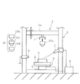
- FIG. 2 is an explanatory diagram illustrating the basic structure of the impact test apparatus.
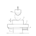
- FIG. 3 is an explanatory view schematically illustrating a test sample that is deformed by a free-falling impact imparting body.
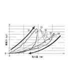
- FIG. 4 is a graph illustrating the relationship between the impact force at room temperature and the amount of intrusion.
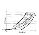
- FIG. 5 is a graph illustrating the relationship between the impact force at 70 ° C. and the amount of intrusion.
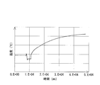
- FIG. 6 is a graph illustrating the change over time of the surface temperature of the test sample.
- FIG. 7 is an explanatory diagram (flow chart) illustrating a flow when selecting an appropriate rubber according to another embodiment of the present invention.
- the rubber selection method of the present invention will be described based on the embodiment shown in the drawings.
- gum used for the target object used while a collision object collides is selected.
- the object is a conveyor belt and the rubber to be selected is an upper cover rubber of the conveyor belt will be described as an example.
- an appropriate test sample (rubber) to be used as the upper cover rubber is selected from a plurality of types of rubber test samples S having different physical properties (for example, viscoelastic properties) by the procedure illustrated in FIG.
- an impact test in which the impact imparting body 10 is freely dropped is performed on a plurality of types of rubber test samples S having different physical properties under predetermined test conditions.
- This test condition is preferably set to a condition corresponding to the environment when the selected rubber (test sample S) is actually used as the upper cover rubber of the conveyor belt.
- the impact test apparatus 1 includes an installation base 2 on which the test sample S is installed, an impact imparting body 10 that freely drops the test sample S, a load meter 5, a displacement meter 6, and a calculation unit 8. Yes. Furthermore, it has a temperature sensor 7 and a temperature controller 9.
- the impact imparting body 10 it is desirable to include a plurality of types of impact imparting bodies 10a, 10b, 10c, and 10d having different specifications such as the lower end shape and weight. From these plural types of specifications, the impact imparting body 10 having specifications approximate to the conveyed product that gives an impact to the upper cover rubber in actual use is selected.
- a beam portion 3a extends between the standing frame 3 and a holding mechanism 4 is provided on the beam portion 3a.
- the beam portion 3a can be arbitrarily moved to a height position and fixed.
- the impact applying body 10a detachably held by the holding mechanism 4 is configured to freely fall toward the test sample S installed on the plate-shaped installation table 2 when the holding is released.
- the load cell 5 is installed below the installation table 2 and measures the impact force acting on the test sample S.
- the displacement meter 6 measures the indentation amount H of the impact imparting body 10 a that has collided with the test sample S by free fall. When the shape of the lower end of the impact imparting body 10 is sharp, the indentation amount H becomes the flaw depth.
- Measurement data of the load meter 5 and the displacement meter 6 is input to the calculation unit 8. As the calculation unit 8, various computers can be used.
- the temperature sensor 7 measures the surface temperature of the test sample S.
- the surface temperature measured by the temperature sensor 7 is input to the calculation unit 8.
- thermography or the like can be used as the temperature sensor 7, thermography or the like.
- the temperature controller 9 heats or cools the test sample S, and sets the temperature of the test sample S to an arbitrary temperature.
- the temperature controller 9 installed on the lower surface of the installation table 2 heats or cools the installation table 2 to indirectly heat or cool the test sample S and set it to an arbitrary temperature.
- a constant temperature case or the like in which the entire test apparatus is covered with a cover and the inside of the cover can be set to an arbitrary atmospheric temperature can be used.
- the procedure for acquiring the data of each item using this impact test apparatus 1 is as follows.
- the test sample S is installed on the installation base 2 illustrated in FIG.
- An appropriate impact imparting body 10a that approximates the actual use condition of the conveyor belt 11 is selected from a plurality of types of impact imparting bodies 10 and attached to the holding mechanism 4. Further, the impact applying body 10 is set to an appropriate height position (for example, a position at a height h from the surface of the test sample S) by moving the beam portion 3a.
- the test sample S is set to a predetermined temperature by the temperature controller 9.
- the holding by the holding mechanism 4 with respect to the impact imparting body 10 is released, and the impact imparting body 10 is freely dropped and collided with the test sample S.
- M is a known mass of the impact imparting body 10.
- the load force 5 sequentially measures the impact force acting on the test sample S. Further, the displacement amount H of the impact imparting body 10 with respect to the test sample S illustrated in FIG.
- the impact force measured by the load meter 5 and the indentation amount H measured by the displacement meter 6 are input to the calculation unit 8. This indentation amount H varies depending on the rubber physical properties.
- FIG. 4 shows measurement data when four types of test samples S (S1 to S4) are tested at room temperature under the same test conditions (when the test sample S is about 20 ° C.).
- FIG. 5 shows measurement data when testing is performed at 70 ° C. by changing only the temperatures of the four types of test samples S (S1 to S4).
- the calculation unit 8 calculates the loss energy E1 absorbed by the test sample S when the impact imparting body 10 and the test sample S collide based on the input measurement data. 4 and 5, the range of the data curve of each test sample S that rises to the right indicates the impact force and the amount of intrusion H from when the impact imparting body 10 contacts the test sample S to the deepest indentation. Shows the relationship. Therefore, the intrusion energy Ea can be calculated by integrating this data curve in this range.
- the range to the left of these data curves shows the relationship between the impact force and the amount of indentation H until the impact imparting body 10 retreats from the test sample S to the deepest position and then rebounds from the test sample 10. ing. Therefore, the repulsive energy Eb can be calculated by integrating this data curve in this range.
- This loss energy E1 (or loss energy E1 / impact energy E) varies depending on rubber physical properties.
- the surface temperature of the test sample S immediately after the impact imparting body 10 bounces can be sequentially measured by the temperature sensor 7.
- the surface temperature measured by the temperature sensor 7 is input to the calculation unit 8. As illustrated in FIG. 6, the surface temperature of the test sample at room temperature is measured, and the change with time can be grasped.
- the calculation unit 8 calculates the thermal energy E2 generated in the test sample S when the impact imparting body 10 and the test sample S collide based on the measured surface temperature and the intrusion amount H.
- the rising temperature ⁇ T (maximum rising temperature ⁇ T) of the test sample S due to the collision with the impact imparting body 10 is found.
- the specific heat c of the test sample S is known in advance.
- the mass m of the test sample S whose temperature has increased is calculated as follows, for example.
- the indentation amount H of the impact imparting body 10 is measured by the displacement meter 6. Since the shape of the impact imparting body 10 is known in advance, for example, the maximum cross-sectional area and the maximum amount of intrusion of the portion of the impact imparting body 10 that is invaded into the test sample S when it is most deeply invaded.
- the volume V calculated by multiplying by H is defined as the volume V of the test sample S whose temperature has increased. Since the specific gravity ⁇ of the test sample S is known in advance, the mass m of the test sample S whose temperature has increased can be calculated by multiplying the volume V and the specific gravity ⁇ .
- the thermal energy E2 can be calculated by multiplying the mass m, the specific heat c, and the rising temperature ⁇ T. This thermal energy E2 varies depending on the rubber physical properties.
- the impact test is performed for each item (loss energy E1, thermal energy E, indentation amount H) from which the data was acquired.
- the relative evaluation of the plurality of types of test samples S performed is performed.
- ⁇ Specific relative evaluation method ranks the superiority of multiple types of test samples S in the items for which data was acquired.
- the loss energy E1 for example, it is evaluated that the greater the loss energy E1, the better the impact resistance, and it is ranked first, second, third, fourth as being excellent in order of the loss energy E1.
- the thermal energy E2 for example, it is evaluated that the larger the thermal energy E2, the better the impact resistance, and the ranking (1st to 4th) is ranked as being superior in the descending order of the thermal energy E2.
- the intrusion amount H for example, the smaller the indentation amount H is, the smaller the flaw depth is. To 4th place.
- a comprehensive evaluation of each test sample S is performed.
- a specific test sample S is selected from a plurality of types of test samples S1 to S4 based on the above-described ranking.
- the test sample S with the highest priority (first place) in that item is specified, and this test sample S is selected.
- preset priorities between the respective items are set in advance. For example, items with high priority are set in the order of loss energy E1, intrusion amount H, and heat energy E2. Then, based on the priority order of the plurality of types of test samples S in each item and the priority order between the respective items set in advance, a specific optimum from among the plurality of types of test samples S1 to S4. Test sample S (rubber) is selected.
- test sample S1 if a test sample S1 has the highest advantage in all items, the test sample S1 is selected.
- the test sample S2 is selected with an emphasis on the order of the test sample S in the item with the highest priority (loss energy E1).
- the present invention data of at least one of the three items of the loss energy E1, the thermal energy E2, and the intrusion amount H, which are closely related to the durability (impact resistance) of the rubber, is acquired. Use. Therefore, by selecting the most suitable rubber based on the order of superiority of the multiple types of test samples S in these items, an appropriate rubber (upper cover rubber) that matches the actual use of the object (conveyor belt) can be obtained. It becomes possible to select.
- an appropriate upper cover rubber according to the life of the conveyor belt. It is also possible to select an upper cover rubber that can make the flaw depth within an allowable range. When selection is performed using the data of the above three items, it is easy to select an appropriate rubber (upper cover rubber) that matches the actual use with high accuracy.
- an impact test is performed using a plurality of test samples S when selecting an appropriate rubber.
- data that has already been accumulated through an impact test is used without performing an impact test.
- At least one item of the three items of data of the loss energy E1, the thermal energy E2, and the intrusion amount H described in the previous embodiment is acquired, and the item from which the data is acquired.
- the correlation between the viscoelastic properties of each test sample S are previously grasped.
- loss coefficient (tan ⁇ ) loss coefficient (tan ⁇ )
- storage elastic modulus (E ′) loss elastic modulus (E ′′) and the like can be used.
- the order of superiority of multiple types of test samples S in the items for which data is acquired is previously grasped.
- the loss energy E1 is evaluated to be superior in impact resistance as the loss energy E1 is larger, and the loss energy E1 is ranked in the order of greater loss energy E1.
- the thermal energy E2 for example, the larger the thermal energy E2, the higher the impact resistance, and the higher the thermal energy E2, the higher the order of the thermal energy E2.
- the intrusion amount H for example, the smaller the intrusion amount H is, the smaller the flaw depth is. .
- a database showing the correlation with the viscoelastic properties of each test sample S is created and stored in a computing device such as a computer. Furthermore, this database associates an order of superiority of a plurality of types of test samples S in each item. Moreover, since the data of each item has temperature dependence, it is good to create the database for every predetermined temperature.
- viscoelastic characteristics of a plurality of types of candidate rubbers are input to the arithmetic unit.
- a specific rubber is selected from a plurality of types of candidate rubbers based on the input viscoelastic characteristics and the above-described correlation and order.
- each item (loss energy E1, energy E2, indentation depth H) and the viscoelastic characteristics that are grasped in advance and the values of the input viscoelastic characteristics, respectively,
- data for each item is calculated.
- the degree of loss energy E1, energy E2, and indentation depth H of each rubber is determined.
- Priorities are set in advance between the items. For example, items with high priority are set in the order of loss energy E1, intrusion amount H, and heat energy E2.
- the object is a conveyor belt and the rubber to be selected is exemplified as an upper cover rubber.
- the present invention is not limited to this.
- Other examples of rubbers that can be selected using the present invention include lower cover rubber for conveyor belts, tread rubber for tires, and the like.
Landscapes
- Chemical & Material Sciences (AREA)
- Health & Medical Sciences (AREA)
- Life Sciences & Earth Sciences (AREA)
- Immunology (AREA)
- Analytical Chemistry (AREA)
- Biochemistry (AREA)
- General Health & Medical Sciences (AREA)
- General Physics & Mathematics (AREA)
- Physics & Mathematics (AREA)
- Pathology (AREA)
- Engineering & Computer Science (AREA)
- Mechanical Engineering (AREA)
- Food Science & Technology (AREA)
- Medicinal Chemistry (AREA)
- Investigating Strength Of Materials By Application Of Mechanical Stress (AREA)
- Belt Conveyors (AREA)
Abstract
Description
2 設置台
3 フレーム
3a 梁部
4 保持機構
5 荷重計
6 変位計
7 温度センサ
8 演算部
9 温度調節器
10 衝撃付与体
S(S1、S2、S3、S4) 試験サンプル
Claims (5)
- 衝突物が衝突しながら使用される対象物に用いるゴムの選定方法において、
物性の異なる複数種類のゴムの試験サンプルに対して衝撃付与体を自由落下させる衝撃試験を所定の試験条件下で行い、前記衝撃付与体が前記試験サンプルに衝突した際に前記試験サンプルにより吸収された損失エネルギと、前記試験サンプルに発生した熱エネルギと、前記試験サンプルに対する前記衝撃付与体の陥入量との3項目のうちの少なくとも1項目のデータを取得し、データを取得した項目における前記複数種類の試験サンプルの優位性の順位に基づいて、前記複数種類の試験サンプルの中から特定の試験サンプルを選定することを特徴とするゴムの選定方法。 - 前記3項目のデータを取得し、それぞれの項目における前記複数種類の試験サンプルの優位性の順位と、予め設定されているそれぞれの項目間の優先順位とに基づいて、前記複数種類の試験サンプルの中から最適な試験サンプルを選定する請求項1に記載のゴムの選定方法。
- 前記物性に少なくとも粘弾性特性が含まれる請求項1または2に記載のゴムの選定方法。
- 衝突物が衝突しながら使用される対象物に用いるゴムの選定方法において、
物性の異なる複数種類のゴムの試験サンプルに対して衝撃付与体を自由落下させる衝撃試験を所定の試験条件下で行い、前記衝撃付与体が前記試験サンプルに衝突した際に前記試験サンプルにより吸収された損失エネルギと、前記試験サンプルに発生した熱エネルギと、前記試験サンプルに対する前記衝撃付与体の陥入量との3項目のデータのうちの少なくとも1項目を取得して、データを取得した項目とそれぞれの前記試験サンプルの粘弾性特性との相関関係と、データを取得した項目における前記複数種類の試験サンプルの優位性の序列とを予め把握しておき、
ゴムを選定する際に、候補となる複数種類のゴムの粘弾性特性と、予め把握している前記相関関係および前記序列とに基づいて、候補となる前記複数種類のゴムの中から特定のゴムを選定することを特徴とするゴムの選定方法。 - 前記対象物がコンベヤベルトである請求項1~4のいずれかに記載のゴムの選定方法。
Priority Applications (4)
| Application Number | Priority Date | Filing Date | Title |
|---|---|---|---|
| DE112017002097.2T DE112017002097B4 (de) | 2016-04-22 | 2017-02-22 | Kautschukauswahlverfahren |
| AU2017252992A AU2017252992B2 (en) | 2016-04-22 | 2017-02-22 | Rubber selection method |
| US16/095,669 US10625942B2 (en) | 2016-04-22 | 2017-02-22 | Rubber selection method |
| CN201780022923.9A CN109073521B (zh) | 2016-04-22 | 2017-02-22 | 橡胶的选定方法 |
Applications Claiming Priority (2)
| Application Number | Priority Date | Filing Date | Title |
|---|---|---|---|
| JP2016-085951 | 2016-04-22 | ||
| JP2016085951A JP6743473B2 (ja) | 2016-04-22 | 2016-04-22 | ゴムの選定方法 |
Publications (1)
| Publication Number | Publication Date |
|---|---|
| WO2017183282A1 true WO2017183282A1 (ja) | 2017-10-26 |
Family
ID=60116842
Family Applications (1)
| Application Number | Title | Priority Date | Filing Date |
|---|---|---|---|
| PCT/JP2017/006494 Ceased WO2017183282A1 (ja) | 2016-04-22 | 2017-02-22 | ゴムの選定方法 |
Country Status (6)
| Country | Link |
|---|---|
| US (1) | US10625942B2 (ja) |
| JP (1) | JP6743473B2 (ja) |
| CN (1) | CN109073521B (ja) |
| AU (1) | AU2017252992B2 (ja) |
| DE (1) | DE112017002097B4 (ja) |
| WO (1) | WO2017183282A1 (ja) |
Families Citing this family (1)
| Publication number | Priority date | Publication date | Assignee | Title |
|---|---|---|---|---|
| JP6743472B2 (ja) * | 2016-04-22 | 2020-08-19 | 横浜ゴム株式会社 | 衝撃試験方法および装置 |
Citations (3)
| Publication number | Priority date | Publication date | Assignee | Title |
|---|---|---|---|---|
| JPH10260123A (ja) * | 1997-03-18 | 1998-09-29 | Bridgestone Corp | 弾性体の物性試験装置 |
| JP2012189533A (ja) * | 2011-03-14 | 2012-10-04 | Yokohama Rubber Co Ltd:The | コンベヤベルトの衝撃試験装置および方法 |
| WO2016042999A1 (ja) * | 2014-09-16 | 2016-03-24 | 横浜ゴム株式会社 | 衝撃試験装置および方法 |
Family Cites Families (13)
| Publication number | Priority date | Publication date | Assignee | Title |
|---|---|---|---|---|
| US4313337A (en) * | 1980-03-17 | 1982-02-02 | The Dow Chemical Company | Apparatus for evaluating the impact resistance of synthetic resinous products |
| CA1204533A (en) * | 1980-11-20 | 1986-05-13 | Akitaro Nakahira | Rubber material |
| US5929316A (en) * | 1997-07-22 | 1999-07-27 | King Design Industrial Co., Ltd. | Air hammer type impact tester |
| DE19904448A1 (de) * | 1999-02-04 | 2000-08-24 | Murat Bajozitovic Bakirov | Verfahren zur zerstörungsfreien Ermittlung mechanischer Eigenschaften von Objektbereichen |
| US7320242B2 (en) * | 2002-03-12 | 2008-01-22 | The University Of Akron | Tensile impact apparatus |
| CN100587463C (zh) * | 2004-07-08 | 2010-02-03 | 日东电工株式会社 | 冲击试验装置及冲击试验方法 |
| JP4619157B2 (ja) * | 2004-07-08 | 2011-01-26 | 日東電工株式会社 | 衝撃試験装置及び衝撃試験方法 |
| JP5227860B2 (ja) | 2009-03-13 | 2013-07-03 | 横浜ゴム株式会社 | コンベヤベルトの衝撃試験方法および装置 |
| JP5486412B2 (ja) | 2010-06-07 | 2014-05-07 | 横浜ゴム株式会社 | コンベヤベルトの耐衝撃性の評価システムおよび評価方法 |
| JP5834486B2 (ja) * | 2011-05-18 | 2015-12-24 | 横浜ゴム株式会社 | コンベヤベルトの評価装置および評価方法 |
| CN103175669A (zh) * | 2011-12-21 | 2013-06-26 | 鸿富锦精密工业(深圳)有限公司 | 撞击头及应用该撞击头的机械冲击试验机 |
| CN204732032U (zh) * | 2015-07-09 | 2015-10-28 | 中国人民解放军空军勤务学院 | 工程教学用冲击试验装置 |
| JP6743472B2 (ja) * | 2016-04-22 | 2020-08-19 | 横浜ゴム株式会社 | 衝撃試験方法および装置 |
-
2016
- 2016-04-22 JP JP2016085951A patent/JP6743473B2/ja active Active
-
2017
- 2017-02-22 DE DE112017002097.2T patent/DE112017002097B4/de active Active
- 2017-02-22 CN CN201780022923.9A patent/CN109073521B/zh active Active
- 2017-02-22 WO PCT/JP2017/006494 patent/WO2017183282A1/ja not_active Ceased
- 2017-02-22 US US16/095,669 patent/US10625942B2/en active Active
- 2017-02-22 AU AU2017252992A patent/AU2017252992B2/en not_active Ceased
Patent Citations (3)
| Publication number | Priority date | Publication date | Assignee | Title |
|---|---|---|---|---|
| JPH10260123A (ja) * | 1997-03-18 | 1998-09-29 | Bridgestone Corp | 弾性体の物性試験装置 |
| JP2012189533A (ja) * | 2011-03-14 | 2012-10-04 | Yokohama Rubber Co Ltd:The | コンベヤベルトの衝撃試験装置および方法 |
| WO2016042999A1 (ja) * | 2014-09-16 | 2016-03-24 | 横浜ゴム株式会社 | 衝撃試験装置および方法 |
Also Published As
| Publication number | Publication date |
|---|---|
| DE112017002097B4 (de) | 2025-05-15 |
| AU2017252992B2 (en) | 2020-06-18 |
| CN109073521B (zh) | 2021-03-09 |
| AU2017252992A1 (en) | 2018-10-25 |
| US10625942B2 (en) | 2020-04-21 |
| CN109073521A (zh) | 2018-12-21 |
| US20190127150A1 (en) | 2019-05-02 |
| DE112017002097T5 (de) | 2019-01-03 |
| JP6743473B2 (ja) | 2020-08-19 |
| JP2017194407A (ja) | 2017-10-26 |
Similar Documents
| Publication | Publication Date | Title |
|---|---|---|
| JP6743472B2 (ja) | 衝撃試験方法および装置 | |
| Celik | Determination of bruise susceptibility of pears (Ankara variety) to impact load by means of FEM-based explicit dynamics simulation | |
| Uhlmann et al. | Discrete element modelling of drag finishing | |
| Curà et al. | Dissipative aspects in thermographic methods | |
| Lee et al. | Fatigue life prediction of solder joints with consideration of frequency, temperature and cracking energy density | |
| JP6743473B2 (ja) | ゴムの選定方法 | |
| JP2012141283A (ja) | 変態塑性係数測定装置および変態塑性係数測定方法 | |
| US10656055B2 (en) | Conveyor belt specification determining method | |
| JP2014202652A (ja) | 材料の耐衝撃曲げ・せん断特性の評価方法 | |
| Liu et al. | Compressive mechanical property analysis of EVA foam: its buffering effects at different impact velocities | |
| Liu et al. | Experimental method and FE simulation model for evaluation of wafer probing parameters | |
| JP7056650B2 (ja) | ゴム部材の耐衝撃性評価方法 | |
| Crochon | Modeling in the Viscoelastic Behavior of Polyimide Matrix at Elevated Temperature | |
| WO2019064758A1 (ja) | コンベヤベルトの寿命予測方法 | |
| JP7110551B2 (ja) | コンベヤベルト | |
| Farroni et al. | Physical modeling of a dynamic dial indicator for the non-destructive evaluation of tire tread viscoelastic characteristics | |
| Lee et al. | Analysis of excessive deformation behavior of a PMMA-touch screen panel laminated material in a high temperature condition | |
| Marco et al. | Heat build-up measurements on SFRP: fast determination of fatigue properties and validation of a fatigue criterion on automotive parts | |
| TH18055U (th) | กระบวนการทำนายคุณสมบัติทางกายภาพจากข้อมูลจากการตรวจวัดในกระบวนการแปรรูปทางอุตสาหกรรม | |
| Wilkus¹ et al. | MULTISCAL SYNERGETIC MODEL OF THE DIE WEAR IN HOT FORGING PROCESS | |
| Omori et al. | Evaluation of drop impact load for portable electronic components | |
| Nassiri et al. | Modeling static bruising in apple fruits: a comparative study, part I: analytical approach | |
| Yamashita et al. | Improvement of Drop-Hammer Compression Test for Rubber Material | |
| WO2016170929A1 (ja) | コンベヤベルトの仕様決定方法 |
Legal Events
| Date | Code | Title | Description |
|---|---|---|---|
| ENP | Entry into the national phase |
Ref document number: 2017252992 Country of ref document: AU Date of ref document: 20170222 Kind code of ref document: A |
|
| 121 | Ep: the epo has been informed by wipo that ep was designated in this application |
Ref document number: 17785627 Country of ref document: EP Kind code of ref document: A1 |
|
| 122 | Ep: pct application non-entry in european phase |
Ref document number: 17785627 Country of ref document: EP Kind code of ref document: A1 |
|
| WWG | Wipo information: grant in national office |
Ref document number: 112017002097 Country of ref document: DE |