WO2017183252A1 - Appareil terminal, appareil station de base et procédé de communication - Google Patents
Appareil terminal, appareil station de base et procédé de communication Download PDFInfo
- Publication number
- WO2017183252A1 WO2017183252A1 PCT/JP2017/003683 JP2017003683W WO2017183252A1 WO 2017183252 A1 WO2017183252 A1 WO 2017183252A1 JP 2017003683 W JP2017003683 W JP 2017003683W WO 2017183252 A1 WO2017183252 A1 WO 2017183252A1
- Authority
- WO
- WIPO (PCT)
- Prior art keywords
- resource
- rat
- subframe
- physical
- predetermined
- Prior art date
Links
- 238000004891 communication Methods 0.000 title claims abstract description 113
- 238000000034 method Methods 0.000 title claims description 123
- 230000005540 biological transmission Effects 0.000 claims abstract description 224
- 238000012545 processing Methods 0.000 claims abstract description 79
- 230000011664 signaling Effects 0.000 claims abstract description 72
- 238000013507 mapping Methods 0.000 description 47
- 238000005259 measurement Methods 0.000 description 45
- 230000008569 process Effects 0.000 description 41
- 238000010586 diagram Methods 0.000 description 29
- 238000007726 management method Methods 0.000 description 25
- 230000006870 function Effects 0.000 description 20
- 238000005516 engineering process Methods 0.000 description 19
- 230000002776 aggregation Effects 0.000 description 15
- 238000004220 aggregation Methods 0.000 description 15
- 238000006243 chemical reaction Methods 0.000 description 8
- 238000001514 detection method Methods 0.000 description 8
- 230000009977 dual effect Effects 0.000 description 8
- 230000000737 periodic effect Effects 0.000 description 8
- 101000741965 Homo sapiens Inactive tyrosine-protein kinase PRAG1 Proteins 0.000 description 7
- 102100038659 Inactive tyrosine-protein kinase PRAG1 Human genes 0.000 description 7
- 230000010267 cellular communication Effects 0.000 description 7
- 238000013468 resource allocation Methods 0.000 description 6
- 230000000694 effects Effects 0.000 description 5
- 230000004044 response Effects 0.000 description 5
- 241000700159 Rattus Species 0.000 description 4
- 230000003321 amplification Effects 0.000 description 4
- 125000004122 cyclic group Chemical group 0.000 description 4
- 230000007274 generation of a signal involved in cell-cell signaling Effects 0.000 description 4
- 238000003199 nucleic acid amplification method Methods 0.000 description 4
- 239000008186 active pharmaceutical agent Substances 0.000 description 3
- 239000000969 carrier Substances 0.000 description 3
- 239000000284 extract Substances 0.000 description 3
- 230000005577 local transmission Effects 0.000 description 3
- 239000011159 matrix material Substances 0.000 description 3
- 238000012544 monitoring process Methods 0.000 description 3
- 238000012937 correction Methods 0.000 description 2
- 230000010354 integration Effects 0.000 description 2
- 230000007774 longterm Effects 0.000 description 2
- 230000001151 other effect Effects 0.000 description 2
- 230000010363 phase shift Effects 0.000 description 2
- 239000004065 semiconductor Substances 0.000 description 2
- 238000000926 separation method Methods 0.000 description 2
- 230000005236 sound signal Effects 0.000 description 2
- 238000012546 transfer Methods 0.000 description 2
- 230000001133 acceleration Effects 0.000 description 1
- 230000003044 adaptive effect Effects 0.000 description 1
- 230000001413 cellular effect Effects 0.000 description 1
- 230000008859 change Effects 0.000 description 1
- 230000000295 complement effect Effects 0.000 description 1
- 239000000470 constituent Substances 0.000 description 1
- 239000006185 dispersion Substances 0.000 description 1
- 239000004973 liquid crystal related substance Substances 0.000 description 1
- 229910044991 metal oxide Inorganic materials 0.000 description 1
- 150000004706 metal oxides Chemical class 0.000 description 1
- 238000010295 mobile communication Methods 0.000 description 1
- 239000013307 optical fiber Substances 0.000 description 1
- 230000002085 persistent effect Effects 0.000 description 1
- 230000007480 spreading Effects 0.000 description 1
- 238000001774 stimulated Raman spectroscopy Methods 0.000 description 1
- 230000001360 synchronised effect Effects 0.000 description 1
Images


Classifications
-
- H—ELECTRICITY
- H04—ELECTRIC COMMUNICATION TECHNIQUE
- H04L—TRANSMISSION OF DIGITAL INFORMATION, e.g. TELEGRAPHIC COMMUNICATION
- H04L5/00—Arrangements affording multiple use of the transmission path
- H04L5/003—Arrangements for allocating sub-channels of the transmission path
- H04L5/0042—Arrangements for allocating sub-channels of the transmission path intra-user or intra-terminal allocation
-
- H—ELECTRICITY
- H04—ELECTRIC COMMUNICATION TECHNIQUE
- H04W—WIRELESS COMMUNICATION NETWORKS
- H04W72/00—Local resource management
- H04W72/04—Wireless resource allocation
- H04W72/044—Wireless resource allocation based on the type of the allocated resource
- H04W72/0446—Resources in time domain, e.g. slots or frames
-
- H—ELECTRICITY
- H04—ELECTRIC COMMUNICATION TECHNIQUE
- H04W—WIRELESS COMMUNICATION NETWORKS
- H04W72/00—Local resource management
- H04W72/04—Wireless resource allocation
- H04W72/044—Wireless resource allocation based on the type of the allocated resource
- H04W72/0453—Resources in frequency domain, e.g. a carrier in FDMA
-
- H—ELECTRICITY
- H04—ELECTRIC COMMUNICATION TECHNIQUE
- H04B—TRANSMISSION
- H04B17/00—Monitoring; Testing
- H04B17/30—Monitoring; Testing of propagation channels
- H04B17/382—Monitoring; Testing of propagation channels for resource allocation, admission control or handover
-
- H—ELECTRICITY
- H04—ELECTRIC COMMUNICATION TECHNIQUE
- H04B—TRANSMISSION
- H04B7/00—Radio transmission systems, i.e. using radiation field
- H04B7/02—Diversity systems; Multi-antenna system, i.e. transmission or reception using multiple antennas
- H04B7/04—Diversity systems; Multi-antenna system, i.e. transmission or reception using multiple antennas using two or more spaced independent antennas
- H04B7/06—Diversity systems; Multi-antenna system, i.e. transmission or reception using multiple antennas using two or more spaced independent antennas at the transmitting station
- H04B7/0613—Diversity systems; Multi-antenna system, i.e. transmission or reception using multiple antennas using two or more spaced independent antennas at the transmitting station using simultaneous transmission
- H04B7/068—Diversity systems; Multi-antenna system, i.e. transmission or reception using multiple antennas using two or more spaced independent antennas at the transmitting station using simultaneous transmission using space frequency diversity
-
- H—ELECTRICITY
- H04—ELECTRIC COMMUNICATION TECHNIQUE
- H04L—TRANSMISSION OF DIGITAL INFORMATION, e.g. TELEGRAPHIC COMMUNICATION
- H04L27/00—Modulated-carrier systems
- H04L27/26—Systems using multi-frequency codes
- H04L27/2601—Multicarrier modulation systems
- H04L27/2602—Signal structure
- H04L27/26025—Numerology, i.e. varying one or more of symbol duration, subcarrier spacing, Fourier transform size, sampling rate or down-clocking
-
- H—ELECTRICITY
- H04—ELECTRIC COMMUNICATION TECHNIQUE
- H04L—TRANSMISSION OF DIGITAL INFORMATION, e.g. TELEGRAPHIC COMMUNICATION
- H04L27/00—Modulated-carrier systems
- H04L27/26—Systems using multi-frequency codes
- H04L27/2601—Multicarrier modulation systems
- H04L27/2647—Arrangements specific to the receiver only
- H04L27/2655—Synchronisation arrangements
- H04L27/2666—Acquisition of further OFDM parameters, e.g. bandwidth, subcarrier spacing, or guard interval length
-
- H—ELECTRICITY
- H04—ELECTRIC COMMUNICATION TECHNIQUE
- H04L—TRANSMISSION OF DIGITAL INFORMATION, e.g. TELEGRAPHIC COMMUNICATION
- H04L5/00—Arrangements affording multiple use of the transmission path
- H04L5/0091—Signaling for the administration of the divided path
-
- H—ELECTRICITY
- H04—ELECTRIC COMMUNICATION TECHNIQUE
- H04L—TRANSMISSION OF DIGITAL INFORMATION, e.g. TELEGRAPHIC COMMUNICATION
- H04L5/00—Arrangements affording multiple use of the transmission path
- H04L5/0091—Signaling for the administration of the divided path
- H04L5/0094—Indication of how sub-channels of the path are allocated
-
- H—ELECTRICITY
- H04—ELECTRIC COMMUNICATION TECHNIQUE
- H04W—WIRELESS COMMUNICATION NETWORKS
- H04W56/00—Synchronisation arrangements
- H04W56/001—Synchronization between nodes
-
- H—ELECTRICITY
- H04—ELECTRIC COMMUNICATION TECHNIQUE
- H04W—WIRELESS COMMUNICATION NETWORKS
- H04W56/00—Synchronisation arrangements
- H04W56/001—Synchronization between nodes
- H04W56/002—Mutual synchronization
-
- H—ELECTRICITY
- H04—ELECTRIC COMMUNICATION TECHNIQUE
- H04W—WIRELESS COMMUNICATION NETWORKS
- H04W72/00—Local resource management
- H04W72/04—Wireless resource allocation
-
- H—ELECTRICITY
- H04—ELECTRIC COMMUNICATION TECHNIQUE
- H04W—WIRELESS COMMUNICATION NETWORKS
- H04W72/00—Local resource management
- H04W72/20—Control channels or signalling for resource management
- H04W72/23—Control channels or signalling for resource management in the downlink direction of a wireless link, i.e. towards a terminal
- H04W72/232—Control channels or signalling for resource management in the downlink direction of a wireless link, i.e. towards a terminal the control data signalling from the physical layer, e.g. DCI signalling
-
- H—ELECTRICITY
- H04—ELECTRIC COMMUNICATION TECHNIQUE
- H04W—WIRELESS COMMUNICATION NETWORKS
- H04W76/00—Connection management
- H04W76/10—Connection setup
- H04W76/15—Setup of multiple wireless link connections
-
- H—ELECTRICITY
- H04—ELECTRIC COMMUNICATION TECHNIQUE
- H04L—TRANSMISSION OF DIGITAL INFORMATION, e.g. TELEGRAPHIC COMMUNICATION
- H04L1/00—Arrangements for detecting or preventing errors in the information received
- H04L1/12—Arrangements for detecting or preventing errors in the information received by using return channel
- H04L1/16—Arrangements for detecting or preventing errors in the information received by using return channel in which the return channel carries supervisory signals, e.g. repetition request signals
- H04L1/18—Automatic repetition systems, e.g. Van Duuren systems
- H04L1/1867—Arrangements specially adapted for the transmitter end
- H04L1/1893—Physical mapping arrangements
-
- H—ELECTRICITY
- H04—ELECTRIC COMMUNICATION TECHNIQUE
- H04L—TRANSMISSION OF DIGITAL INFORMATION, e.g. TELEGRAPHIC COMMUNICATION
- H04L47/00—Traffic control in data switching networks
- H04L47/70—Admission control; Resource allocation
-
- H—ELECTRICITY
- H04—ELECTRIC COMMUNICATION TECHNIQUE
- H04L—TRANSMISSION OF DIGITAL INFORMATION, e.g. TELEGRAPHIC COMMUNICATION
- H04L67/00—Network arrangements or protocols for supporting network services or applications
- H04L67/14—Session management
- H04L67/141—Setup of application sessions
-
- H—ELECTRICITY
- H04—ELECTRIC COMMUNICATION TECHNIQUE
- H04W—WIRELESS COMMUNICATION NETWORKS
- H04W48/00—Access restriction; Network selection; Access point selection
- H04W48/18—Selecting a network or a communication service
-
- H—ELECTRICITY
- H04—ELECTRIC COMMUNICATION TECHNIQUE
- H04W—WIRELESS COMMUNICATION NETWORKS
- H04W88/00—Devices specially adapted for wireless communication networks, e.g. terminals, base stations or access point devices
- H04W88/02—Terminal devices
- H04W88/06—Terminal devices adapted for operation in multiple networks or having at least two operational modes, e.g. multi-mode terminals
Definitions
- the present disclosure relates to a terminal device, a base station device, and a communication method.
- LTE Long Term Evolution
- LTE-A LTE-Advanced
- LTE-A Pro LTE-Advanced Pro
- NR New Radio
- NRAT New Radio Access
- EUTRA Evolved Universal Terrestrial Radio Access
- FEUTRA Frether EUTRA
- LTE and NR a base station device (base station) is also called eNodeB (evolved NodeB), and a terminal device (mobile station, mobile station device, terminal) is also called UE (User Equipment).
- LTE and NR are cellular communication systems in which a plurality of areas covered by a base station apparatus are arranged in a cell shape. A single base station apparatus may manage a plurality of cells.
- NR is a radio access system for LTE that is different from LTE as a next-generation radio access method.
- Technology NR is eMBB (Enhanced mobile broadband), mMTC (Massive machine type) communications) and URLLC (Ultra reliable and low) It is an access technology that can handle various use cases including latency communications.
- NR is examined with the aim of a technology framework that addresses usage scenarios, requirements, and deployment scenarios in those use cases. Details of NR scenarios and requirements are disclosed in Non-Patent Document 1.
- transmission signal parameters such as subcarrier spacing and symbol length are optimally designed according to use cases.
- transmission signal parameters physical parameters
- the terminal device using the extension technology multiplexes with the conventional LTE terminal device from the viewpoint of frequency utilization efficiency. Therefore, the extension technology in LTE is required to be backward compatible, and may limit the extension technology. As a result, such limitations can have an impact on the overall system transmission efficiency.
- the present disclosure has been made in view of the above problems, and an object thereof is to transmit the entire system by flexibly designing according to various use cases in a communication system in which a base station device and a terminal device communicate. It is an object of the present invention to provide a base station device, a terminal device, a communication system, a communication method, and an integrated circuit that can greatly improve the efficiency.
- a terminal device that communicates with a base station device, and sets up at least one first RAT and at least one second RAT by higher layer signaling from the base station device.
- a layer processing unit, and a reception unit that receives a transmission signal in the first RAT and a transmission signal in the second RAT.
- the transmission signal in the first RAT is 1 in each subframe. Mapped to resource elements configured based on one physical parameter, the transmission signal in the second RAT is mapped to resource elements configured based on one or more physical parameters in each of the subframes; and Based on one physical parameter in a predetermined resource included in each of the subframes. Are mapped to resource elements configured Te, the terminal device is provided.
- a base station apparatus that communicates with a terminal apparatus, wherein at least one first RAT and at least one second RAT are set for the terminal apparatus by higher layer signaling.
- An upper layer processing unit, and a transmission unit that transmits a transmission signal in the first RAT and a transmission signal in the second RAT, and the transmission signal in the first RAT includes subframes, respectively.
- the transmission signal in the second RAT is mapped to resource elements configured based on one or more physical parameters in each of the subframes, And one physical parameter in a predetermined resource included in each of the subframes Are mapped to resource elements configured based, base station apparatus is provided.
- a communication method used in a terminal apparatus that communicates with a base station apparatus, wherein at least one first RAT and at least one second are transmitted by higher layer signaling from the base station apparatus. And a step of receiving a transmission signal in the first RAT and a transmission signal in the second RAT, wherein the transmission signal in the first RAT is a subframe.
- the transmission signal in the first RAT is a subframe.
- the transmission signal in the second RAT is mapped to resource elements configured on the basis of one or more physical parameters in each of the subframes.
- the communication method is provided.
- a communication method used in a base station apparatus that communicates with a terminal apparatus, wherein at least one first RAT and at least one second are transmitted to the terminal apparatus by higher layer signaling. And a step of transmitting a transmission signal in the first RAT and a transmission signal in the second RAT, wherein the transmission signal in the first RAT is a subframe.
- the transmission signal in the first RAT is a subframe.
- the transmission signal in the second RAT is mapped to resource elements configured on the basis of one or more physical parameters in each of the subframes.
- the communication method is provided.
- FIG. 38 is a block diagram illustrating an example of a schematic configuration of a car navigation device 920 to which the technology according to the present disclosure can be applied.
- the wireless communication system includes at least a base station device 1 and a terminal device 2.
- the base station device 1 can accommodate a plurality of terminal devices.
- the base station device 1 can be connected to other base station devices by means of an X2 interface.
- the base station apparatus 1 can be connected to an EPC (Evolved Packet Core) by means of an S1 interface.
- the base station apparatus 1 can be connected to an MME (Mobility Management Entity) by means of an S1-MME interface, and can be connected to an S-GW (Serving Gateway) by means of an S1-U interface.
- the S1 interface supports a many-to-many connection between the MME and / or S-GW and the base station apparatus 1.
- the base station apparatus 1 and the terminal device 2 support LTE and / or NR, respectively.
- each of the base station device 1 and the terminal device 2 supports one or more radio access technologies (RAT).
- RAT includes LTE and NR.
- One RAT corresponds to one cell (component carrier). That is, when multiple RATs are supported, each RAT corresponds to a different cell.
- a cell is a combination of downlink resources, uplink resources, and / or side links.
- LTE is referred to as a first RAT
- NR is referred to as a second RAT.
- Downlink communication is communication from the base station device 1 to the terminal device 2.
- Uplink communication is communication from the terminal device 2 to the base station device 1.
- the side link communication is communication from the terminal device 2 to another terminal device 2.
- Side link communication is defined for proximity direct detection and proximity direct communication between terminal devices.
- the side link communication can use the same frame configuration as the uplink and downlink. Further, side link communication may be limited to a part (subset) of uplink resources and / or downlink resources.
- the base station apparatus 1 and the terminal apparatus 2 can support communication using a set of one or more cells in the downlink, uplink, and / or side link.
- a set of a plurality of cells is also referred to as carrier aggregation or dual connectivity. Details of carrier aggregation and dual connectivity will be described later.
- Each cell uses a predetermined frequency bandwidth. A maximum value, a minimum value, and a settable value in a predetermined frequency bandwidth can be defined in advance.
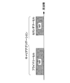
- FIG. 1 is a diagram showing an example of component carrier settings in the present embodiment.
- one LTE cell and two NR cells are set.
- One LTE cell is set as a primary cell.
- the two NR cells are set as a primary secondary cell and a secondary cell, respectively.
- the two NR cells are integrated by carrier aggregation.
- the LTE cell and the NR cell are integrated by dual connectivity. Note that the LTE cell and the NR cell may be integrated by carrier aggregation.
- the NR since the NR can be assisted by the LTE cell that is the primary cell, the NR may not support some functions such as a function for performing stand-alone communication.
- the function for stand-alone communication includes a function necessary for initial connection.
- FIG. 2 is a diagram illustrating an example of component carrier settings in the present embodiment.
- two NR cells are set.
- the two NR cells are set as a primary cell and a secondary cell, respectively, and are integrated by carrier aggregation.
- the support of the LTE cell becomes unnecessary by supporting the function for the NR cell to perform stand-alone communication.
- the two NR cells may be integrated by dual connectivity.
- a radio frame composed of 10 ms (milliseconds) is defined.
- Each radio frame is composed of two half frames.
- the time interval of the half frame is 5 ms.
- Each half frame is composed of five subframes.
- the subframe time interval is 1 ms and is defined by two consecutive slots.
- the slot time interval is 0.5 ms.
- the i-th subframe in the radio frame is composed of a (2 ⁇ i) th slot and a (2 ⁇ i + 1) th slot. That is, 10 subframes are defined in each radio frame.
- the subframe includes a downlink subframe, an uplink subframe, a special subframe, a sidelink subframe, and the like.
- the downlink subframe is a subframe reserved for downlink transmission.
- An uplink subframe is a subframe reserved for uplink transmission.
- the special subframe is composed of three fields. The three fields include DwPTS (Downlink Pilot Time Slot), GP (Guard Period), and UpPTS (Uplink Pilot Time Slot). The total length of DwPTS, GP, and UpPTS is 1 ms.
- DwPTS is a field reserved for downlink transmission.
- UpPTS is a field reserved for uplink transmission.
- GP is a field in which downlink transmission and uplink transmission are not performed. Note that the special subframe may be configured only by DwPTS and GP, or may be configured only by GP and UpPTS.
- the special subframe is arranged between the downlink subframe and the uplink subframe in TDD, and is used for switching from the downlink subframe to the uplink subframe.
- the side link subframe is a subframe reserved or set for side link communication.
- the side link is used for proximity direct communication and proximity direct detection between terminal devices.
- a single radio frame includes a downlink subframe, an uplink subframe, a special subframe, and / or a sidelink subframe. Also, a single radio frame may be composed of only downlink subframes, uplink subframes, special subframes, or sidelink subframes.
- the radio frame configuration is defined by the frame configuration type.
- Frame configuration type 1 is applicable only to FDD.
- Frame configuration type 2 is applicable only to TDD.
- Frame configuration type 3 is applicable only to operation of LAA (Licensed Assisted Access) secondary cells.
- each of the 10 subframes in one radio frame corresponds to one of a downlink subframe, an uplink subframe, and a special subframe.
- Subframe 0, subframe 5 and DwPTS are always reserved for downlink transmission.
- the subframe immediately following UpPTS and its special subframe is always reserved for uplink transmission.
- each subframe in one radio frame is reserved for downlink transmission.
- the terminal device 2 treats each subframe as an empty subframe.
- the terminal apparatus 2 assumes that no signal and / or channel exists in the subframe unless a predetermined signal, channel and / or downlink transmission is detected in the subframe.
- Downlink transmission is dedicated in one or more consecutive subframes.
- the first subframe of the downlink transmission may start from anywhere within that subframe.
- the last subframe of the downlink transmission may be either completely occupied or dedicated at a time interval defined by DwPTS.
- 10 subframes in one radio frame may be reserved for uplink transmission. Further, each of the 10 subframes in one radio frame may correspond to any of a downlink subframe, an uplink subframe, a special subframe, and a sidelink subframe.
- the base station apparatus 1 may transmit a physical downlink channel and a physical downlink signal in DwPTS of the special subframe.
- the base station apparatus 1 can restrict PBCH transmission in DwPTS of the special subframe.
- the terminal device 2 may transmit the physical uplink channel and the physical uplink signal in the UpPTS of the special subframe.
- the terminal device 2 can restrict transmission of some physical uplink channels and physical uplink signals in the UpPTS of the special subframe.
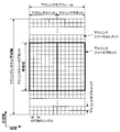
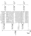
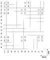
- FIG. 3 is a diagram illustrating an example of an LTE downlink subframe in the present embodiment.
- the diagram shown in FIG. 3 is also referred to as an LTE downlink resource grid.
- the base station apparatus 1 can transmit an LTE physical downlink channel and / or an LTE physical downlink signal in a downlink subframe to the terminal apparatus 2.
- the terminal device 2 can receive an LTE physical downlink channel and / or an LTE physical downlink signal in the downlink subframe from the base station device 1.
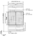
- FIG. 4 is a diagram illustrating an example of an LTE uplink subframe in the present embodiment.
- the diagram shown in FIG. 4 is also referred to as an LTE uplink resource grid.
- the terminal device 2 can transmit an LTE physical uplink channel and / or an LTE physical uplink signal in an uplink subframe to the base station device 1.
- the base station apparatus 1 can receive an LTE physical uplink channel and / or an LTE physical uplink signal in an uplink subframe from the terminal apparatus 2.
- LTE physical resources can be defined as follows.
- One slot is defined by a plurality of symbols.
- the physical signal or physical channel transmitted in each of the slots is represented by a resource grid.
- the resource grid is defined by a plurality of subcarriers in the frequency direction and a plurality of OFDM symbols in the time direction.
- the resource grid is defined by a plurality of subcarriers in the frequency direction and a plurality of SC-FDMA symbols in the time direction.
- the number of subcarriers or resource blocks may be determined depending on the cell bandwidth.
- the number of symbols in one slot is determined by the CP (Cyclic Prefix) type.
- the CP type is a normal CP or an extended CP.
- the number of OFDM symbols or SC-FDMA symbols constituting one slot is seven.
- the number of OFDM symbols or SC-FDMA symbols constituting one slot is six.
- Each element in the resource grid is called a resource element.
- the resource element is identified using a subcarrier index (number) and a symbol index (number).
- the OFDM symbol or SC-FDMA symbol is also simply referred to as a symbol.
- the resource block is used for mapping a certain physical channel (such as PDSCH or PUSCH) to a resource element.
- the resource block includes a virtual resource block and a physical resource block.
- a certain physical channel is mapped to a virtual resource block.
- a virtual resource block is mapped to a physical resource block.
- One physical resource block is defined by a predetermined number of consecutive symbols in the time domain.
- One physical resource block is defined from a predetermined number of consecutive subcarriers in the frequency domain. The number of symbols and the number of subcarriers in one physical resource block are determined based on the type of CP in the cell, the subcarrier spacing, and / or parameters set by higher layers.
- one physical resource block is composed of (7 ⁇ 12) resource elements. Physical resource blocks are numbered from 0 in the frequency domain. Further, two resource blocks in one subframe corresponding to the same physical resource block number are defined as physical resource block pairs (PRB pair, RB pair).
- the predetermined parameter is a parameter related to the transmission signal.
- Parameters related to the transmission signal include CP length, subcarrier interval, number of symbols in one subframe (predetermined time length), number of subcarriers in one resource block (predetermined frequency band), multiple access scheme, and signal Includes waveforms.
- the downlink signal and the uplink signal are generated using one predetermined parameter in each predetermined time length (for example, subframe).
- the terminal apparatus 2 generates a downlink signal transmitted from the base station apparatus 1 and an uplink signal transmitted to the base station apparatus 1 with one predetermined parameter for each predetermined time length.
- the base station apparatus 1 generates a downlink signal transmitted to the terminal apparatus 2 and an uplink signal transmitted from the terminal apparatus 2 with one predetermined parameter for each predetermined time length.
- ⁇ Frame structure of NR in this embodiment> In each of the NR cells, one or more predetermined parameters are used in a certain predetermined time length (for example, subframe). That is, in the NR cell, the downlink signal and the uplink signal are each generated with one or more predetermined parameters in a predetermined time length.
- the terminal apparatus 2 generates a downlink signal transmitted from the base station apparatus 1 and an uplink signal transmitted to the base station apparatus 1 with one or more predetermined parameters in a predetermined time length.
- the base station apparatus 1 generates a downlink signal to be transmitted to the terminal apparatus 2 and an uplink signal to be transmitted from the terminal apparatus 2 with one or more predetermined parameters for each predetermined time length.
- the predetermined method includes FDM (Frequency Division Multiplexing), TDM (Time Division Multiplexing), CDM (Code Division Multiplexing), and / or SDM (Spatial Division Multiplexing).
- FDM Frequency Division Multiplexing
- TDM Time Division Multiplexing
- CDM Code Division Multiplexing
- SDM Spatial Division Multiplexing
- a plurality of types of combinations of predetermined parameters set in the NR cell can be specified in advance as a parameter set.
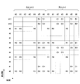
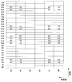
- FIG. 5 is a diagram illustrating an example of a parameter set relating to a transmission signal in the NR cell.
- the parameters related to the transmission signal included in the parameter set are the subcarrier interval, the number of subcarriers per resource block in the NR cell, the number of symbols per subframe, and the CP length type.
- the CP length type is a CP length type used in the NR cell.
- CP length type 1 corresponds to a normal CP in LTE
- CP length type 2 corresponds to an extended CP in LTE.
- Parameter sets related to transmission signals in the NR cell can be individually defined for the downlink and uplink. Also, parameter sets related to transmission signals in the NR cell can be set independently for the downlink and uplink.
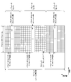
- FIG. 6 is a diagram illustrating an example of an NR downlink subframe in the present embodiment.
- a signal generated using the parameter set 1, the parameter set 0, and the parameter set 2 is FDM in the cell (system bandwidth).
- the diagram shown in FIG. 6 is also referred to as the NR downlink resource grid.
- the base station apparatus 1 can transmit an NR physical downlink channel and / or an NR physical downlink signal in a downlink subframe to the terminal apparatus 2.
- the terminal device 2 can receive the NR physical downlink channel and / or the NR physical downlink signal in the downlink subframe from the base station device 1.
- FIG. 7 is a diagram illustrating an example of an uplink subframe of NR in the present embodiment.
- a signal generated using parameter set 1, parameter set 0, and parameter set 2 is FDM in a cell (system bandwidth).
- the diagram shown in FIG. 6 is also referred to as the NR uplink resource grid.
- the base station apparatus 1 can transmit an NR physical uplink channel and / or an NR physical uplink signal in an uplink subframe to the terminal apparatus 2.
- the terminal apparatus 2 can receive the NR physical uplink channel and / or the NR physical uplink signal in the uplink subframe from the base station apparatus 1.
- An antenna port is defined so that a propagation channel carrying one symbol can be inferred from a propagation channel carrying another symbol at the same antenna port. For example, it can be assumed that different physical resources in the same antenna port are transmitted on the same propagation channel. In other words, a symbol at a certain antenna port can be demodulated by estimating a propagation channel using a reference signal at that antenna port. There is one resource grid per antenna port.
- An antenna port is defined by a reference signal. Each reference signal can define a plurality of antenna ports.
- antenna port 0 to 3 are antenna ports to which CRS is transmitted. That is, the PDSCH transmitted through the antenna ports 0 to 3 can be demodulated by the CRS corresponding to the antenna ports 0 to 3.
- the two antenna ports satisfy a predetermined condition, they can be expressed as quasi-identical positions (QCL: Quasi co-location).
- the predetermined condition is that the wide-area characteristics of a propagation channel carrying a symbol at one antenna port can be inferred from the propagation channel carrying a symbol at another antenna port.
- Global characteristics include delay dispersion, Doppler spread, Doppler shift, average gain and / or average delay.
- the antenna port number may be defined differently for each RAT, or may be defined in common between RATs.
- antenna ports 0 to 3 in LTE are antenna ports through which CRS is transmitted.
- the antenna ports 0 to 3 can be antenna ports through which CRS similar to LTE is transmitted.
- an antenna port for transmitting a CRS similar to LTE can have an antenna port number different from antenna ports 0 to 3.
- the predetermined antenna port number can be applied to LTE and / or NR.
- the physical channel includes a physical downlink channel, a physical uplink channel, and a physical side link channel.
- the physical signal includes a physical downlink signal, a physical uplink signal, and a side link physical signal.
- the physical channel and physical signal in LTE are also referred to as LTE physical channel and LTE physical signal, respectively.
- the physical channel and physical signal in NR are also referred to as NR physical channel and NR physical signal, respectively.
- the LTE physical channel and the NR physical channel can be defined as different physical channels.
- the LTE physical signal and the NR physical signal can be defined as different physical signals.
- the LTE physical channel and the NR physical channel are also simply referred to as physical channels, and the LTE physical signal and the NR physical signal are also simply referred to as physical signals. That is, the description for the physical channel can be applied to both the LTE physical channel and the NR physical channel.
- the description for the physical signal can be applied to both the LTE physical signal and the NR physical signal.
- Physical downlink channels include physical broadcast channel (PBCH: Physical Broadcast Channel), PCFICH (Physical Control Format Indicator Channel), PHICH (Physical Hybrid automatic repeat request Indicator Channel), physical downlink control channel (PDCCH: Physical Downlink Control Channel). , Enhanced physical downlink control channel (EPDCCH: EnhancedEnhancePDCCH), MTC (Machine Type Communication) physical downlink control channel (MPDCCH: MTC PDCCH), relay physical downlink control channel (R-PDCCH: Relay PDCCH), physical downlink Includes shared channel (PDSCH: Physical Downlink Shared Channel), PMCH (Physical Multicast Channel), etc.
- PBCH Physical Broadcast Channel
- PCFICH Physical Control Format Indicator Channel
- PHICH Physical Hybrid automatic repeat request Indicator Channel
- PDCCH Physical Downlink Control Channel
- EPCCH Enhanced Physical downlink control channel
- MTC Machine Type Communication
- MTC Machine Type Communication
- R-PDCCH Relay PDCCH
- Physical downlink Includes shared channel
- the physical downlink signal includes a synchronization signal (SS: Synchronization signal), a downlink reference signal (DL-RS: Downlink Reference Signal), a detection signal (DS: Discovery signal), and the like.
- SS Synchronization signal
- DL-RS Downlink Reference Signal
- DS Discovery signal
- the synchronization signal includes a primary synchronization signal (PSS) and a secondary synchronization signal (SSS).
- PSS primary synchronization signal
- SSS secondary synchronization signal
- the reference signal in the downlink includes a cell-specific reference signal (CRS), a terminal-specific reference signal associated with PDSCH (PDSCH-DMRS), and a demodulation associated with EPDCCH.
- CRS cell-specific reference signal
- PDSCH-DMRS terminal-specific reference signal associated with PDSCH
- demodulation associated with EPDCCH REDCCH-DMRS: Demodulation reference signal associated with EPDCCH
- PRS Positioning Reference Signal
- CSI reference signal CSI reference signal
- TRS Tracking reference signal
- PDSCH-DMRS is also referred to as URS associated with PDSCH or simply URS.
- EPDCCH-DMRS is also referred to as DMRS related to EPDCCH or simply DMRS.
- CSI-RS includes NZP CSI-RS (Non-Zero Power CSI-RS).
- Downlink resources include ZP CSI-RS (Zero Power CSI-RS), CSI-IM (Channel State Information-Interference Measurement), and the like.
- the physical uplink channel includes a physical uplink shared channel (PUSCH), a physical uplink control channel (PUCCH), a physical random access channel (PRACH), and the like. .
- PUSCH physical uplink shared channel
- PUCCH physical uplink control channel
- PRACH physical random access channel
- the physical uplink signal includes an uplink reference signal (UL-RS).
- UL-RS uplink reference signal
- the uplink reference signal includes an uplink demodulation signal (UL-DMRS: Uplink demodulation signal), a sounding reference signal (SRS: Sounding reference signal), and the like.
- UL-DMRS is associated with PUSCH or PUCCH transmission.
- SRS is not associated with PUSCH or PUCCH transmission.
- Physical side link channels include physical side link broadcast channel (PSBCH: Physical Sidelink Broadcast Channel), physical side link control channel (PSCCH: Physical Sidelink Control Channel), physical side link detection channel (PSDCH: Physical Sidelink Discovery Channel), and physical Includes side link shared channel (PSSCH).
- PSBCH Physical Sidelink Broadcast Channel
- PSCCH Physical Sidelink Control Channel
- PSDCH Physical Sidelink Discovery Channel
- PSSCH physical Includes side link shared channel
- Physical channels and physical signals are also simply called channels and signals. That is, the physical downlink channel, the physical uplink channel, and the physical side link channel are also referred to as a downlink channel, an uplink channel, and a side link channel, respectively.
- the physical downlink signal, the physical uplink signal, and the physical side link signal are also referred to as a downlink signal, an uplink signal, and a side link signal, respectively.
- BCH, MCH, UL-SCH and DL-SCH are transport channels.
- a channel used in the medium access control (MAC) layer is called a transport channel.
- the unit of the transport channel used in the MAC layer is also called a transport block (transport block: TB) or a MAC PDU (Protocol Data Unit).
- transport block transport block: TB
- MAC PDU Network Data Unit
- HARQ Hybrid Automatic Repeat reQuest
- the transport block is a unit of data that the MAC layer delivers to the physical layer. In the physical layer, the transport block is mapped to a code word, and an encoding process is performed for each code word.
- the downlink reference signal and the uplink reference signal are also simply referred to as a reference signal (RS).
- RS reference signal
- LTE physical channel and LTE physical signal in this embodiment As already described, the description for the physical channel and the physical signal can be applied to the LTE physical channel and the LTE physical signal, respectively.
- the LTE physical channel and the LTE physical signal are referred to as follows.
- LTE physical downlink channels include LTE-PBCH, LTE-PCFICH, LTE-PHICH, LTE-PDCCH, LTE-EPDCCH, LTE-MPDCCH, LTE-R-PDCCH, LTE-PDSCH, and LTE-PMCH.
- LTE physical downlink signals include LTE-SS, LTE-DL-RS, LTE-DS, and the like.
- LTE-SS includes LTE-PSS, LTE-SSS, and the like.
- LTE-RS includes LTE-CRS, LTE-PDSCH-DMRS, LTE-EPDCCH-DMRS, LTE-PRS, LTE-CSI-RS, LTE-TRS, and the like.
- LTE physical uplink channels include LTE-PUSCH, LTE-PUCCH, LTE-PRACH, and the like.
- the LTE physical uplink signal includes LTE-UL-RS.
- LTE-UL-RS includes LTE-UL-DMRS, LTE-SRS, and the like.
- the LTE physical side link channel includes LTE-PSBCH, LTE-PSCCH, LTE-PSDCH, LTE-PSSCH, and the like.
- NR physical channel and NR physical signal in this embodiment As already described, the description for the physical channel and the physical signal can be applied to the NR physical channel and the NR physical signal, respectively.
- the NR physical channel and the NR physical signal are referred to as follows.
- NR physical downlink channels include NR-PBCH, NR-PCFICH, NR-PHICH, NR-PDCCH, NR-EPDCCH, NR-MPDCCH, NR-R-PDCCH, NR-PDSCH, and NR-PMCH.
- NR physical downlink signals include NR-SS, NR-DL-RS, NR-DS, and the like.
- NR-SS includes NR-PSS, NR-SSS, and the like.
- the NR-RS includes NR-CRS, NR-PDSCH-DMRS, NR-EPDCCH-DMRS, NR-PRS, NR-CSI-RS, NR-TRS, and the like.
- NR physical uplink channels include NR-PUSCH, NR-PUCCH, NR-PRACH, and the like.
- NR physical uplink signal includes NR-UL-RS.
- NR-UL-RS includes NR-UL-DMRS and NR-SRS.
- NR physical side link channel includes NR-PSBCH, NR-PSCCH, NR-PSDCH, NR-PSSCH, and the like.
- the PBCH is used to broadcast an MIB (Master Information Block) that is broadcast information unique to the serving cell of the base station apparatus 1.
- MIB Master Information Block
- PBCH is transmitted only in subframe 0 in the radio frame.
- the MIB can be updated at 40 ms intervals.
- the PBCH is repeatedly transmitted at a period of 10 ms. Specifically, an initial MIB transmission is performed in subframe 0 in a radio frame that satisfies the condition that the remainder of SFN (System Frame Number) divided by 4 is 0, and in subframe 0 in all other radio frames. MIB retransmission is performed.
- SFN is a radio frame number (system frame number).
- MIB is system information. For example, the MIB includes information indicating SFN.
- PCFICH is used to transmit information on the number of OFDM symbols used for transmission of PDCCH.
- a region indicated by PCFICH is also referred to as a PDCCH region.
- Information transmitted by PCFICH is also referred to as CFI (Control Format Indicator).
- the PHICH transmits HARQ-ACK (HARQ indicator, HARQ feedback, response information) indicating ACK (ACKnowledgement) or NACK (Negative ACKnowledgement) for the uplink data (Uplink Shared Channel: UL-SCH) received by the base station apparatus 1. Used to do. For example, when HARQ-ACK indicating ACK is received, the corresponding uplink data is not retransmitted. For example, when the terminal apparatus 2 receives HARQ-ACK indicating NACK, the terminal apparatus 2 retransmits corresponding uplink data in a predetermined uplink subframe.
- a certain PHICH transmits a HARQ-ACK for certain uplink data.
- the base station apparatus 1 transmits each HARQ-ACK for a plurality of uplink data included in the same PUSCH using a plurality of PHICHs.
- PDCCH and EPDCCH are used to transmit downlink control information (DCI). Mapping of information bits of downlink control information is defined as a DCI format.
- the downlink control information includes a downlink grant (downlink grant) and an uplink grant (uplink grant).
- the downlink grant is also referred to as a downlink assignment or a downlink allocation.
- the PDCCH is transmitted by a set of one or more continuous CCEs (Control Channel Elements).
- the CCE is composed of nine REGs (Resource Element Groups).
- the REG is composed of four resource elements.
- EPDCCH is transmitted by a set of one or more continuous ECCEs (Enhanced Control Channel Elements).
- ECCE is composed of multiple EREGs (Enhanced Resource Element Group).
- the downlink grant is used for scheduling the PDSCH in a certain cell.
- the downlink grant is used for scheduling the PDSCH in the same subframe as the subframe in which the downlink grant is transmitted.
- the uplink grant is used for scheduling the PUSCH in a certain cell.
- the uplink grant is used for scheduling a single PUSCH in a subframe that is four or more times after the subframe in which the uplink grant is transmitted.
- the CRC parity bit is added to DCI.
- the CRC parity bit is scrambled by RNTI (Radio Network Temporary Identifier).
- the RNTI is an identifier that can be defined or set according to the purpose of the DCI.
- the RNTI is set as an identifier preliminarily specified in the specification, an identifier set as information specific to a cell, an identifier set as information specific to the terminal device 2, or information specific to a group belonging to the terminal device 2.
- Identifier For example, in monitoring PDCCH or EPDCCH, the terminal device 2 descrambles a CRC parity bit added to DCI with a predetermined RNTI and identifies whether the CRC is correct. If the CRC is correct, it can be seen that the DCI is the DCI for the terminal device 2.
- PDSCH is used to transmit downlink data (Downlink Shared Channel: DL-SCH).
- DL-SCH Downlink Shared Channel
- the PDSCH is also used for transmitting higher layer control information.
- PMCH is used to transmit multicast data (Multicast Channel: MCH).
- a plurality of PDCCHs may be frequency, time and / or spatially multiplexed.
- a plurality of EPDCCHs may be frequency, time and / or spatially multiplexed.
- a plurality of PDSCHs may be frequency, time and / or spatially multiplexed.
- PDCCH, PDSCH and / or EPDCCH may be frequency, time and / or spatially multiplexed.
- the synchronization signal is used for the terminal apparatus 2 to synchronize the downlink frequency domain and / or time domain.
- the synchronization signal is PSS (Primary Synchronization Signal) and SSS (Secondary Synchronization Signal).
- the synchronization signal is arranged in a predetermined subframe in the radio frame. For example, in the TDD scheme, the synchronization signal is arranged in subframes 0, 1, 5, and 6 in the radio frame. In the FDD scheme, the synchronization signal is arranged in subframes 0 and 5 in the radio frame.
- PSS may be used for coarse frame / symbol timing synchronization (time domain synchronization) and cell group identification.
- SSS may be used for more accurate frame timing synchronization and cell identification. That is, frame timing synchronization and cell identification can be performed by using PSS and SSS.
- the downlink reference signal is transmitted from the terminal apparatus 2 to the physical downlink channel propagation path estimation, propagation path correction, and downlink CSI (Channel State Information, channel state information) and / or measurement of positioning of the terminal device 2 is used.
- the physical downlink channel propagation path estimation, propagation path correction, and downlink CSI Channel State Information, channel state information
- CRS is transmitted in the entire bandwidth of the subframe.
- CRS is used to receive (demodulate) PBCH, PDCCH, PHICH, PCFICH, and PDSCH.
- the CRS may be used for the terminal device 2 to calculate downlink channel state information.
- PBCH, PDCCH, PHICH, and PCFICH are transmitted by an antenna port used for transmission of CRS.
- CRS supports 1, 2 or 4 antenna port configurations.
- CRS is transmitted on one or more of antenna ports 0-3.
- URS related to PDSCH is transmitted in a subframe and a band used for transmission of PDSCH related to URS. URS is used to demodulate the PDSCH with which the URS is associated. The URS associated with the PDSCH is transmitted on one or more of the antenna ports 5, 7-14.
- the PDSCH is transmitted by an antenna port used for transmission of CRS or URS based on the transmission mode and the DCI format.
- the DCI format 1A is used for scheduling of PDSCH transmitted through an antenna port used for CRS transmission.
- the DCI format 2D is used for scheduling of the PDSCH transmitted through the antenna port used for URS transmission.
- DMRS related to EPDCCH is transmitted in subframes and bands used for transmission of EPDCCH related to DMRS.
- DMRS is used to demodulate the EPDCCH with which DMRS is associated.
- the EPDCCH is transmitted through an antenna port used for DMRS transmission.
- the DMRS associated with the EPDCCH is transmitted on one or more of the antenna ports 107-114.
- CSI-RS is transmitted in the set subframe. Resources for transmitting the CSI-RS are set by the base station apparatus 1.
- the CSI-RS is used for the terminal apparatus 2 to calculate downlink channel state information.
- the terminal device 2 performs signal measurement (channel measurement) using CSI-RS.
- CSI-RS supports configuration of some or all antenna ports of 1, 2, 4, 8, 12, 16, 24 and 32.
- CSI-RS is transmitted on one or more of antenna ports 15-46.
- the supported antenna port may be determined based on the terminal device capability of the terminal device 2, the setting of the RRC parameter, and / or the set transmission mode.
- ZP CSI-RS resources are set by higher layers. ZP CSI-RS resources are transmitted with zero output power. That is, no ZP CSI-RS resource is transmitted. PDSCH and EPDCCH are not transmitted in the resource set by ZP CSI-RS.
- ZP CSI-RS resources are used by neighboring cells to transmit NZP CSI-RS.
- ZP CSI-RS resources are used to measure CSI-IM.
- the ZP CSI-RS resource is a resource to which a predetermined channel such as PDSCH is not transmitted. In other words, a predetermined channel is mapped by excluding ZP CSI-RS resources (rate matching and puncturing).
- the CSI-IM resource is set by the base station apparatus 1.
- the CSI-IM resource is a resource used for measuring interference in CSI measurement.
- the CSI-IM resource can be set by overlapping (overlapping) a part of the ZP CSI-RS resource. For example, when a CSI-IM resource is set to overlap with a part of a ZP CSI-RS resource, a signal from a cell performing CSI measurement is not transmitted with the resource. In other words, the base station apparatus 1 does not transmit PDSCH or EPDCCH or the like in the resource set by CSI-IM. Therefore, the terminal device 2 can perform CSI measurement efficiently.
- the MBSFN RS is transmitted in the entire band of the subframe used for PMCH transmission.
- the MBSFN RS is used for PMCH demodulation.
- PMCH is transmitted through an antenna port used for transmission of MBSFN RS.
- the MBSFN RS is transmitted via the antenna port 4.
- PRS is used for the terminal device 2 to measure the positioning of the terminal device 2.
- the PRS is transmitted through the antenna port 6.
- TRS can be mapped only to a predetermined subframe. For example, TRS is mapped to subframes 0 and 5.
- the TRS can use the same configuration as part or all of the CRS.
- the position of the resource element to which the TRS is mapped can be the same as the position of the resource element to which the CRS of antenna port 0 is mapped.
- a sequence (value) used for TRS can be determined based on information set through PBCH, PDCCH, EPDCCH, or PDSCH (RRC signaling).
- a sequence (value) used for TRS can be determined based on parameters such as a cell ID (for example, a physical layer cell identifier) and a slot number.
- the sequence (value) used for TRS can be determined by a method (formula) different from the sequence (value) used for CRS of antenna port 0.
- the PUCCH is a physical channel used for transmitting uplink control information (UPCI).
- the uplink control information includes downlink channel state information (CSI), scheduling request (SR) indicating a request for PUSCH resources, downlink data (Transport block: TB, Downlink-Shared Channel: DL).
- -SCH downlink data for HARQ-ACK.
- HARQ-ACK is also referred to as ACK / NACK, HARQ feedback, or response information.
- HARQ-ACK for downlink data indicates ACK, NACK, or DTX.
- PUSCH is a physical channel used for transmitting uplink data (Uplink-Shared Channel: UL-SCH).
- the PUSCH may also be used to transmit HARQ-ACK and / or channel state information along with uplink data. Also, the PUSCH may be used to transmit only channel state information or only HARQ-ACK and channel state information.
- PRACH is a physical channel used to transmit a random access preamble.
- the PRACH can be used for the terminal device 2 to synchronize with the base station device 1 in the time domain.
- PRACH is an initial connection establishment procedure (processing), a handover procedure, a connection re-establishment procedure, synchronization for uplink transmission (timing adjustment), and / or PUSCH resource request. Also used to indicate
- a plurality of PUCCHs are frequency, time, space and / or code multiplexed.
- a plurality of PUSCHs may be frequency, time, space and / or code multiplexed.
- PUCCH and PUSCH may be frequency, time, space and / or code multiplexed.
- the PRACH may be arranged over a single subframe or two subframes. A plurality of PRACHs may be code-multiplexed.
- Uplink DMRS is related to transmission of PUSCH or PUCCH.
- DMRS is time-multiplexed with PUSCH or PUCCH.
- the base station apparatus 1 may use DMRS to perform PUSCH or PUCCH propagation path correction.
- PUSCH transmission includes multiplexing and transmitting PUSCH and DMRS.
- transmission of PUCCH includes multiplexing and transmitting PUCCH and DMRS.
- the uplink DMRS is also referred to as UL-DMRS.
- SRS is not related to PUSCH or PUCCH transmission.
- the base station apparatus 1 may use SRS in order to measure the uplink channel state.
- the SRS is transmitted using the last SC-FDMA symbol in the uplink subframe. That is, the SRS is arranged in the last SC-FDMA symbol in the uplink subframe.
- the terminal device 2 can restrict simultaneous transmission of SRS and PUCCH, PUSCH and / or PRACH in an SC-FDMA symbol of a certain cell.
- the terminal apparatus 2 transmits PUSCH and / or PUCCH using an SC-FDMA symbol excluding the last SC-FDMA symbol in the uplink subframe in an uplink subframe of a certain cell, and the uplink subframe
- the SRS can be transmitted using the last SC-FDMA symbol in the frame. That is, in a certain uplink subframe of a certain cell, the terminal device 2 can transmit SRS, PUSCH and PUCCH.
- trigger type 0 SRS and trigger type 1 SRS are defined as SRSs having different trigger types.
- the trigger type 0 SRS is transmitted when parameters related to the trigger type 0 SRS are set by higher layer signaling.
- the trigger type 1 SRS is transmitted when a parameter related to the trigger type 1 SRS is set by higher layer signaling and transmission is requested by an SRS request included in the DCI format 0, 1A, 2B, 2C, 2D, or 4.
- the SRS request is included in both FDD and TDD for DCI formats 0, 1A, and 4, and is included only in TDD for DCI formats 2B, 2C, and 2D.
- a resource element group is used to define a mapping between resource elements and control channels.
- REG is used for mapping of PDCCH, PHICH, or PCFICH.
- the REG is composed of four consecutive resource elements that are not used for CRS in the same OFDM symbol and in the same resource block.
- the REG is configured from the first OFDM symbol to the fourth OFDM symbol in the first slot in a certain subframe.
- Extended resource element group is used to define the mapping between resource elements and extended control channels.
- EREG is used for EPDCCH mapping.
- One resource block pair is composed of 16 EREGs. Each EREG is assigned a number from 0 to 15 for each resource block pair.
- Each EREG is composed of nine resource elements excluding resource elements used for DM-RS associated with EPDCCH in one resource block pair.
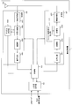
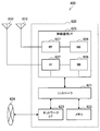
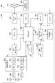
- FIG. 8 is a schematic block diagram illustrating the configuration of the base station device 1 of the present embodiment.
- the base station apparatus 1 includes an upper layer processing unit 101, a control unit 103, a receiving unit 105, a transmitting unit 107, and a transmission / reception antenna 109.
- the reception unit 105 includes a decoding unit 1051, a demodulation unit 1053, a demultiplexing unit 1055, a radio reception unit 1057, and a channel measurement unit 1059.
- the transmission unit 107 includes an encoding unit 1071, a modulation unit 1073, a multiplexing unit 1075, a radio transmission unit 1077, and a downlink reference signal generation unit 1079.
- the base station apparatus 1 can support one or more RATs. Part or all of the units included in the base station apparatus 1 shown in FIG. 8 can be individually configured according to the RAT.
- the reception unit 105 and the transmission unit 107 are individually configured with LTE and NR.
- the NR cell a part or all of each unit included in the base station apparatus 1 shown in FIG.
- the radio reception unit 1057 and the radio transmission unit 1077 can be individually configured according to a parameter set related to a transmission signal.
- the upper layer processing unit 101 includes a medium access control (MAC) layer, a packet data integration protocol (Packet Data Convergence Protocol: PDCP) layer, a radio link control (Radio Link Control: RLC) layer, a radio resource control (Radio). Process Resource Control: RRC) layer. Further, the upper layer processing unit 101 generates control information for controlling the reception unit 105 and the transmission unit 107 and outputs the control information to the control unit 103.
- MAC medium access control
- PDCP Packet Data Convergence Protocol
- RLC Radio Link Control
- Radio Radio
- RRC Radio Resource Control
- the control unit 103 controls the reception unit 105 and the transmission unit 107 based on the control information from the higher layer processing unit 101.
- the control unit 103 generates control information for the upper layer processing unit 101 and outputs the control information to the upper layer processing unit 101.
- the control unit 103 inputs the decoded signal from the decoding unit 1051 and the channel estimation result from the channel measurement unit 1059.
- the control unit 103 outputs a signal to be encoded to the encoding unit 1071.
- the control unit 103 is used to control all or part of the base station apparatus 1.
- the upper layer processing unit 101 performs processing and management related to RAT control, radio resource control, subframe setting, scheduling control, and / or CSI report control.
- the processing and management in the upper layer processing unit 101 is performed for each terminal device or for the terminal devices connected to the base station device.
- the processing and management in the upper layer processing unit 101 may be performed only by the upper layer processing unit 101, or may be acquired from an upper node or another base station device. Further, the processing and management in the upper layer processing unit 101 may be performed individually according to the RAT. For example, the upper layer processing unit 101 individually performs processing and management in LTE and processing and management in NR.
- management related to RAT is performed.
- management related to LTE and / or management related to NR is performed.
- Management regarding NR includes setting and processing of parameter sets regarding transmission signals in the NR cell.
- radio resource control in the upper layer processing unit 101, generation and / or management of downlink data (transport block), system information, RRC message (RRC parameter), and / or MAC control element (CE) is performed. Done.
- subframe setting in the upper layer processing unit 101 subframe setting, subframe pattern setting, uplink-downlink setting, uplink reference UL-DL setting, and / or downlink reference UL-DL setting are managed. Is called.
- the subframe setting in higher layer processing section 101 is also referred to as base station subframe setting.
- the subframe setting in the higher layer processing unit 101 can be determined based on the uplink traffic volume and the downlink traffic volume. Further, the subframe setting in the upper layer processing unit 101 can be determined based on the scheduling result of the scheduling control in the upper layer processing unit 101.
- the frequency and subframe to which a physical channel is allocated, the physical channel's A coding rate, a modulation scheme, transmission power, and the like are determined.
- the control unit 103 generates control information (DCI format) based on the scheduling result of scheduling control in the upper layer processing unit 101.
- the CSI report of the terminal device 2 is controlled.
- the setting related to the CSI reference resource to be assumed for calculating the CSI in the terminal device 2 is controlled.
- the receiving unit 105 receives a signal transmitted from the terminal device 2 via the transmission / reception antenna 109 in accordance with control from the control unit 103, further performs reception processing such as separation, demodulation, and decoding, and receives the received information. Output to the control unit 103. Note that the reception process in the reception unit 105 is performed based on a setting specified in advance or a setting notified from the base station apparatus 1 to the terminal apparatus 2.
- the radio reception unit 1057 converts the uplink signal received via the transmission / reception antenna 109 into an intermediate frequency (down-conversion), removes unnecessary frequency components, and appropriately maintains the signal level. Control of amplification level, quadrature demodulation based on in-phase and quadrature components of received signal, conversion from analog signal to digital signal, removal of guard interval (GI), and / or fast Fourier transform (Fast Fourier transform) Extract frequency domain signals by Transform: FFT).
- GI guard interval
- FFT fast Fourier transform
- the demultiplexing unit 1055 separates an uplink channel such as PUCCH or PUSCH and / or an uplink reference signal from the signal input from the radio reception unit 1057.
- the demultiplexing unit 1055 outputs the uplink reference signal to the channel measurement unit 1059.
- the demultiplexing unit 1055 performs channel compensation for the uplink channel from the channel estimation value input from the channel measurement unit 1059.
- the demodulation unit 1053 receives a received signal using a modulation scheme such as BPSK (Binary Phase Shift Keying), QPSK (Quadrature Phase Shift Keying), 16QAM (Quadrature Amplitude Modulation), 64QAM, or 256QAM for the modulation symbol of the uplink channel. Is demodulated.
- Demodulation section 1053 separates and demodulates the MIMO multiplexed uplink channel.
- the decoding unit 1051 performs a decoding process on the demodulated uplink channel encoded bits.
- the decoded uplink data and / or uplink control information is output to the control unit 103.
- Decoding section 1051 performs decoding processing for each transport block for PUSCH.
- the channel measurement unit 1059 measures the propagation path estimation value and / or channel quality from the uplink reference signal input from the demultiplexing unit 1055, and outputs it to the demultiplexing unit 1055 and / or the control unit 103.
- UL-DMRS measures a channel estimation value for channel compensation for PUCCH or PUSCH
- SRS measures channel quality in the uplink.
- the transmission unit 107 performs transmission processing such as encoding, modulation, and multiplexing on the downlink control information and the downlink data input from the higher layer processing unit 101 according to the control from the control unit 103. For example, the transmission unit 107 generates and multiplexes PHICH, PDCCH, EPDCCH, PDSCH, and a downlink reference signal, and generates a transmission signal. Note that the transmission processing in the transmission unit 107 is based on settings specified in advance, settings notified from the base station apparatus 1 to the terminal apparatus 2, or settings notified via the PDCCH or EPDCCH transmitted in the same subframe. Done.
- the encoding unit 1071 performs HARQ indicator (HARQ-ACK), downlink control information, and downlink data input from the control unit 103 with predetermined encoding such as block encoding, convolutional encoding, and turbo encoding. Encoding is performed using a method.
- the modulation unit 1073 modulates the coded bits input from the coding unit 1071 with a predetermined modulation method such as BPSK, QPSK, 16QAM, 64QAM, 256QAM.
- the downlink reference signal generation unit 1079 generates a downlink reference signal based on a physical cell identifier (PCI), an RRC parameter set in the terminal device 2, and the like.
- Multiplexer 1075 multiplexes the modulation symbols and downlink reference signals for each channel and arranges them in a predetermined resource element.
- the radio transmission unit 1077 converts the signal from the multiplexing unit 1075 into a time-domain signal by inverse fast Fourier transform (IFFT), adds a guard interval, generates a baseband digital signal, Performs conversion to analog signal, quadrature modulation, conversion from intermediate frequency signal to high frequency signal (up-convert), removal of excess frequency components, power amplification, etc. to generate a transmission signal .
- IFFT inverse fast Fourier transform
- the transmission signal output from the wireless transmission unit 1077 is transmitted from the transmission / reception antenna 109.
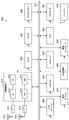
- FIG. 9 is a schematic block diagram showing the configuration of the terminal device 2 of the present embodiment.
- the terminal device 2 includes an upper layer processing unit 201, a control unit 203, a reception unit 205, a transmission unit 207, and a transmission / reception antenna 209.
- the reception unit 205 includes a decoding unit 2051, a demodulation unit 2053, a demultiplexing unit 2055, a radio reception unit 2057, and a channel measurement unit 2059.
- the transmission unit 207 includes an encoding unit 2071, a modulation unit 2073, a multiplexing unit 2075, a radio transmission unit 2077, and an uplink reference signal generation unit 2079.
- the terminal device 2 can support one or more RATs. Some or all of the units included in the terminal device 2 illustrated in FIG. 9 can be individually configured according to the RAT.
- the reception unit 205 and the transmission unit 207 are individually configured with LTE and NR.
- the NR cell some or all of the units included in the terminal device 2 shown in FIG. 9 can be individually configured according to the parameter set related to the transmission signal.
- the radio reception unit 2057 and the radio transmission unit 2077 can be individually configured according to a parameter set related to a transmission signal.
- the higher layer processing unit 201 outputs the uplink data (transport block) to the control unit 203.
- the upper layer processing unit 201 includes a medium access control (MAC) layer, a packet data integration protocol (Packet Data Convergence Protocol: PDCP) layer, a radio link control (Radio Link Control: RLC) layer, a radio resource control (Radio). Process Resource Control: RRC) layer. Further, the upper layer processing unit 201 generates control information for controlling the reception unit 205 and the transmission unit 207 and outputs the control information to the control unit 203.
- MAC medium access control
- PDCP Packet Data Convergence Protocol
- RLC Radio Link Control
- RRC Radio Resource Control
- the control unit 203 controls the reception unit 205 and the transmission unit 207 based on the control information from the higher layer processing unit 201.
- the control unit 203 generates control information for the upper layer processing unit 201 and outputs the control information to the upper layer processing unit 201.
- the control unit 203 inputs the decoded signal from the decoding unit 2051 and the channel estimation result from the channel measurement unit 2059.
- the control unit 203 outputs a signal to be encoded to the encoding unit 2071. Further, the control unit 203 may be used to control all or part of the terminal device 2.
- the upper layer processing unit 201 performs processing and management related to RAT control, radio resource control, subframe setting, scheduling control, and / or CSI report control.
- the processing and management in the upper layer processing unit 201 are performed based on settings specified in advance and / or settings based on control information set or notified from the base station apparatus 1.
- the control information from the base station apparatus 1 includes an RRC parameter, a MAC control element, or DCI.
- the processing and management in the upper layer processing unit 201 may be performed individually according to the RAT.
- the upper layer processing unit 201 individually performs processing and management in LTE and processing and management in NR.
- management related to RAT is performed.
- management related to LTE and / or management related to NR is performed.
- Management regarding NR includes setting and processing of parameter sets regarding transmission signals in the NR cell.
- radio resource control in the higher layer processing unit 201 management of setting information in the own apparatus is performed.
- radio resource control in the upper layer processing unit 201 generation and / or management of uplink data (transport block), system information, RRC message (RRC parameter), and / or MAC control element (CE) is performed. Done.
- the subframe setting in the upper layer processing unit 201 the subframe setting in the base station apparatus 1 and / or a base station apparatus different from the base station apparatus 1 is managed.
- the subframe configuration includes uplink or downlink configuration, subframe pattern configuration, uplink-downlink configuration, uplink reference UL-DL configuration, and / or downlink reference UL-DL configuration for the subframe.
- the subframe setting in the higher layer processing unit 201 is also referred to as terminal subframe setting.
- control information for performing control related to scheduling for the reception unit 205 and the transmission unit 207 is generated based on DCI (scheduling information) from the base station apparatus 1.
- control related to CSI reporting to the base station apparatus 1 is performed.
- the channel measurement unit 2059 controls settings related to CSI reference resources that are assumed to calculate CSI.
- resources (timing) used for reporting CSI are controlled based on DCI and / or RRC parameters.
- the receiving unit 205 receives the signal transmitted from the base station apparatus 1 via the transmission / reception antenna 209 according to the control from the control unit 203, and further performs reception processing such as separation, demodulation, decoding, and the like. Is output to the control unit 203. Note that the reception process in the reception unit 205 is performed based on a predetermined setting or a notification or setting from the base station apparatus 1.
- the radio reception unit 2057 converts the uplink signal received via the transmission / reception antenna 209 to an intermediate frequency (down-conversion), removes unnecessary frequency components, and appropriately maintains the signal level. Control of amplification level, quadrature demodulation based on in-phase and quadrature components of received signal, conversion from analog signal to digital signal, removal of guard interval (GI), and / or fast Fourier transform (Fast Fourier transform) Extracts frequency domain signals using Transform (FFT).
- FFT Fast Fourier transform
- the demultiplexing unit 2055 separates a downlink channel such as PHICH, PDCCH, EPDCCH, or PDSCH, a downlink synchronization signal, and / or a downlink reference signal from the signal input from the radio reception unit 2057.
- the demultiplexing unit 2055 outputs the downlink reference signal to the channel measurement unit 2059.
- the demultiplexing unit 2055 performs channel compensation for the downlink channel from the channel estimation value input from the channel measurement unit 2059.
- the demodulator 2053 demodulates the received signal using a modulation scheme such as BPSK, QPSK, 16QAM, 64QAM, 256QAM, etc., with respect to the downlink channel modulation symbols.
- the demodulator 2053 separates and demodulates the MIMO multiplexed downlink channel.
- the decoding unit 2051 performs a decoding process on the demodulated downlink channel encoded bits.
- the decoded downlink data and / or downlink control information is output to the control unit 203.
- the decoding unit 2051 performs a decoding process for each transport block on the PDSCH.
- the channel measurement unit 2059 measures the estimated value of the propagation path and / or the channel quality from the downlink reference signal input from the demultiplexing unit 2055 and outputs it to the demultiplexing unit 2055 and / or the control unit 203.
- the downlink reference signal used for measurement by the channel measurement unit 2059 may be determined based on at least the transmission mode set by the RRC parameter and / or other RRC parameters.
- DL-DMRS measures an estimated value of a propagation path for performing propagation path compensation for PDSCH or EPDCCH.
- CRS measures a channel estimation value for performing channel compensation for PDCCH or PDSCH and / or a channel in the downlink for reporting CSI.
- CSI-RS measures the channel in the downlink for reporting CSI.
- the channel measurement unit 2059 calculates RSRP (Reference Signal Received Power) and / or RSRQ (Reference Signal Received Quality) based on the CRS, CSI-RS, or detection signal, and outputs it to the upper layer processing unit
- the transmission unit 207 performs transmission processing such as encoding, modulation, and multiplexing on the uplink control information and the uplink data input from the higher layer processing unit 201 according to the control from the control unit 203. For example, the transmission unit 207 generates and multiplexes an uplink channel such as PUSCH or PUCCH and / or an uplink reference signal, and generates a transmission signal. Note that the transmission processing in the transmission unit 207 is performed based on settings specified in advance or settings or notifications from the base station apparatus 1.
- the encoding unit 2071 encodes the HARQ indicator (HARQ-ACK), the uplink control information, and the uplink data input from the control unit 203 with predetermined encoding such as block encoding, convolutional encoding, and turbo encoding. Encoding is performed using a method.
- the modulation unit 2073 modulates the coded bits input from the coding unit 2071 using a predetermined modulation method such as BPSK, QPSK, 16QAM, 64QAM, or 256QAM.
- the uplink reference signal generation unit 2079 generates an uplink reference signal based on the RRC parameter set in the terminal device 2 and the like.
- Multiplexing section 2075 multiplexes the modulation symbols and uplink reference signals for each channel and arranges them in a predetermined resource element.
- the radio transmission unit 2077 converts the signal from the multiplexing unit 2075 into a time-domain signal by inverse fast Fourier transform (IFFT), adds a guard interval, generates a baseband digital signal, Performs conversion to analog signal, quadrature modulation, conversion from intermediate frequency signal to high frequency signal (up-convert), removal of excess frequency components, power amplification, etc. to generate a transmission signal .
- IFFT inverse fast Fourier transform
- the transmission signal output from the wireless transmission unit 2077 is transmitted from the transmission / reception antenna 209.
- the base station apparatus 1 and the terminal apparatus 2 can use various methods for control information signaling (notification, notification, and setting), respectively.
- Signaling of control information can be performed in various layers.
- the signaling of control information includes physical layer signaling that is signaling through the physical layer (layer), RRC signaling that is signaling through the RRC layer, and MAC signaling that is signaling through the MAC layer.
- the RRC signaling is dedicated RRC signaling (Dedicated RRC signaling) for notifying control information unique to the terminal device 2 or common RRC signaling (Common RRC signaling) for notifying control information unique to the base station device 1.
- Signaling used by higher layers as viewed from the physical layer, such as RRC signaling and MAC signaling is also referred to as upper layer signaling.
- RRC signaling is realized by signaling RRC parameters.
- MAC signaling is realized by signaling a MAC control element.
- Physical layer signaling is realized by signaling downlink control information (DCI: Downlink Control Information) or uplink control information (UCI: Uplink Control Information).
- DCI Downlink Control Information
- UCI Uplink Control Information
- the RRC parameter and the MAC control element are transmitted using PDSCH or PUSCH.
- DCI is transmitted using PDCCH or EPDCCH.
- UCI is transmitted using PUCCH or PUSCH.
- RRC signaling and MAC signaling are used to signal semi-static control information and are also referred to as semi-static signaling.
- Physical layer signaling is used to signal dynamic control information and is also referred to as dynamic signaling.
- DCI is used for PDSCH scheduling or PUSCH scheduling.
- the UCI is used for CSI reporting, HARQ-ACK reporting, and / or scheduling request (SR).
- SR scheduling request
- the DCI is notified using a DCI format having a predefined field.
- predetermined information bits are mapped.
- DCI notifies downlink scheduling information, uplink scheduling information, side link scheduling information, aperiodic CSI report request, or uplink transmission power command.
- the DCI format monitored by the terminal device 2 is determined by the transmission mode set for each serving cell. That is, a part of the DCI format monitored by the terminal device 2 can be different depending on the transmission mode.
- the terminal device 2 in which the downlink transmission mode 1 is set monitors the DCI format 1A and the DCI format 1.
- the terminal device 2 in which the downlink transmission mode 4 is set monitors the DCI format 1A and the DCI format 2.
- the terminal device 2 in which the uplink transmission mode 1 is set monitors the DCI format 0.
- the terminal device 2 in which the uplink transmission mode 2 is set monitors the DCI format 0 and the DCI format 4.
- the control region in which the PDCCH that notifies the DCI for the terminal device 2 is not notified, and the terminal device 2 detects the DCI for the terminal device 2 by blind decoding (blind detection). Specifically, the terminal device 2 monitors a set of PDCCH candidates in the serving cell. Monitoring means attempting to decode with all monitored DCI formats for each of the PDCCHs in the set. For example, the terminal device 2 tries to decode all the aggregation levels, PDCCH candidates, and DCI formats that may be transmitted to the terminal device 2. The terminal device 2 recognizes the DCI (PDCCH) that has been successfully decoded (detected) as the DCI (PDCCH) for the terminal device 2.
- PDCCH DCI
- Cyclic Redundancy Check is added to DCI.
- the CRC is used for DCI error detection and DCI blind detection.
- CRC CRC parity bit
- RNTI Radio Network Temporary Identifier
- the terminal device 2 detects whether it is DCI for the terminal device 2 based on the RNTI. Specifically, the terminal device 2 descrambles the bit corresponding to the CRC with a predetermined RNTI, extracts the CRC, and detects whether the corresponding DCI is correct.
- RNTI is specified or set according to the purpose and application of DCI.
- RNTI is C-RNTI (Cell-RNTI), SPS C-RNTI (Semi Persistent Scheduling C-RNTI), SI-RNTI (System Information-RNTI), P-RNTI (Paging-RNTI), RA-RNTI (Random Access) -RNTI), TPC-PUCCH-RNTI (Transmit Power Control-PUCCH-RNTI), TPC-PUSCH-RNTI (Transmit Power Control-PUSCH-RNTI), Temporary C-RNTI, M-RNTI (MBMS (Multimedia Broadcast Multicast Services) ) -RNTI) and eIMTA-RNTI.
- C-RNTI Cell-RNTI
- SPS C-RNTI Semi Persistent Scheduling C-RNTI
- SI-RNTI System Information-RNTI
- P-RNTI Paging-RNTI
- RA-RNTI Random Access
- TPC-PUCCH-RNTI Transmit Power
- C-RNTI and SPS C-RNTI are RNTIs specific to the terminal device 2 in the base station device 1 (cell), and are identifiers for identifying the terminal device 2.
- C-RNTI is used to schedule PDSCH or PUSCH in a certain subframe.
- the SPS C-RNTI is used to activate or release periodic scheduling of resources for PDSCH or PUSCH.
- a control channel having a CRC scrambled by SI-RNTI is used for scheduling an SIB (System Information Block).
- SIB System Information Block
- a control channel with a CRC scrambled with P-RNTI is used to control paging.
- a control channel having a CRC scrambled with RA-RNTI is used to schedule a response to RACH.
- a control channel having a CRC scrambled by TPC-PUCCH-RNTI is used for power control of PUCCH.
- a control channel having a CRC scrambled by TPC-PUSCH-RNTI is used to perform power control of PUSCH.
- a control channel having a CRC scrambled with Temporary C-RNTI is used by a mobile station apparatus for which C-RNTI is not set or recognized.
- a control channel with CRC scrambled with M-RNTI is used to schedule MBMS.
- a control channel having a CRC scrambled by eIMTA-RNTI is used for notifying information on TDD UL / DL configuration of a TDD serving cell in dynamic TDD (eIMTA). Note that the DCI format may be scrambled not only by the above RNTI but also by a new RNTI.
- Scheduling information includes information for performing scheduling in units of resource blocks or resource block groups as frequency domain scheduling.
- the resource block group is a set of consecutive resource blocks, and indicates resources allocated to terminal devices to be scheduled.
- the size of the resource block group is determined according to the system bandwidth.
- DCI is transmitted using a control channel such as PDCCH or EPDCCH.
- the terminal device 2 monitors a set of PDCCH candidates and / or a set of EPDCCH candidates of one or more activated serving cells configured by RRC signaling.
- monitoring means trying to decode PDCCH and / or EPDCCH in a set corresponding to all monitored DCI formats.
- the PDCCH candidate set or EPDCCH candidate set is also called a search space.
- a search space a shared search space (CSS) and a terminal-specific search space (USS) are defined.
- the CSS may be defined only for the search space for PDCCH.
- CSS Common Search Space
- the base station apparatus 1 maps a common control channel to a CSS among a plurality of terminal apparatuses, thereby reducing resources for transmitting the control channel.
- USS UE-specific Search Space
- the USS is a search space set using at least parameters specific to the terminal device 2. Therefore, the USS is a search space unique to the terminal device 2, and a control channel unique to the terminal device 2 can be individually transmitted. Therefore, the base station apparatus 1 can efficiently map control channels unique to a plurality of terminal apparatuses.
- USS may be set so as to be used in common by a plurality of terminal devices. Since a common USS is set for a plurality of terminal devices, parameters unique to the terminal device 2 are set so as to have the same value among the plurality of terminal devices. For example, a unit set to the same parameter among a plurality of terminal devices is a cell, a transmission point, a group of predetermined terminal devices, or the like.
- the search space for each aggregation level is defined by a set of PDCCH candidates.
- Each PDCCH is transmitted using a set of one or more CCEs (Control Channel Elements).
- the number of CCEs used for one PDCCH is also referred to as an aggregation level. For example, the number of CCEs used for one PDCCH is 1, 2, 4 or 8.
- the search space for each aggregation level is defined by a set of EPDCCH candidates.
- Each EPDCCH is transmitted using a set of one or more ECCEs (Enhanced Control Channel Elements).
- the number of ECCEs used for one EPDCCH is also referred to as an aggregation level. For example, the number of ECCEs used for one EPDCCH is 1, 2, 4, 8, 16, or 32.
- the number of PDCCH candidates or the number of EPDCCH candidates is determined based on at least the search space and the aggregation level. For example, in CSS, the number of PDCCH candidates at aggregation levels 4 and 8 is 4 and 2, respectively. For example, in USS, the numbers of PDCCH candidates in aggregations 1, 2, 4, and 8 are 6, 6, 2, and 2, respectively.
- Each ECCE is composed of multiple EREGs (Enhanced resource element groups).
- EREG is used to define the mapping of EPDCCH to resource elements.
- 16 EREGs numbered from 0 to 15, are defined. That is, EREG0 to EREG15 are defined in each RB pair.
- EREG0 to EREG15 are periodically defined by giving priority to the frequency direction with respect to resource elements other than resource elements to which predetermined signals and / or channels are mapped. For example, the resource element to which the demodulation reference signal associated with the EPDCCH transmitted through the antenna ports 107 to 110 is mapped does not define EREG.
- the number of ECCEs used for one EPDCCH depends on the EPDCCH format and is determined based on other parameters.
- the number of ECCEs used for one EPDCCH is also referred to as an aggregation level.
- the number of ECCEs used for one EPDCCH is determined based on the number of resource elements that can be used for EPDCCH transmission in one RB pair, the EPDCCH transmission method, and the like.
- the number of ECCEs used for one EPDCCH is 1, 2, 4, 8, 16, or 32.
- the number of EREGs used for one ECCE is determined based on the type of subframe and the type of cyclic prefix, and is 4 or 8. As transmission methods of EPDCCH, distributed transmission and localized transmission are supported.
- EPDCCH can use distributed transmission or local transmission.
- Distributed transmission and local transmission differ in the mapping of ECCE to EREG and RB pairs.
- one ECCE is configured using EREGs of a plurality of RB pairs.
- one ECCE is configured using one RB pair of EREGs.
- the base station apparatus 1 performs settings related to the EPDCCH for the terminal apparatus 2.
- the terminal device 2 monitors a plurality of EPDCCHs based on the setting from the base station device 1.
- a set of RB pairs with which the terminal device 2 monitors the EPDCCH can be set.
- the set of RB pairs is also referred to as an EPDCCH set or an EPDCCH-PRB set.
- One or more EPDCCH sets can be set for one terminal device 2.
- Each EPDCCH set is composed of one or more RB pairs.
- the setting regarding EPDCCH can be performed individually for each EPDCCH set.
- the base station apparatus 1 can set a predetermined number of EPDCCH sets for the terminal apparatus 2. For example, up to two EPDCCH sets can be configured as EPDCCH set 0 and / or EPDCCH set 1. Each of the EPDCCH sets can be configured with a predetermined number of RB pairs. Each EPDCCH set constitutes one set of a plurality of ECCEs. The number of ECCEs configured in one EPDCCH set is determined based on the number of RB pairs set as the EPDCCH set and the number of EREGs used for one ECCE. If the number of ECCEs configured in one EPDCCH set is N, each EPDCCH set configures ECCEs numbered from 0 to N-1. For example, when the number of EREGs used for one ECCE is 4, an EPDCCH set composed of four RB pairs constitutes 16 ECCEs.
- the terminal device 2 reports (reports) CSI to the base station device 1.
- the base station apparatus 1 controls time and frequency resources used for reporting CSI.
- the terminal device 2 is configured for CSI from the base station device 1 by RRC signaling.
- one or more CSI processes are set in a predetermined transmission mode.
- the CSI reported by the terminal device 2 corresponds to the CSI process.
- the CSI process is a unit of control or setting related to CSI.
- Each of the CSI processes can independently configure settings for CSI-RS resources, CSI-IM resources, periodic CSI reporting (eg, reporting period and offset), and / or aperiodic CSI reporting.
- CSI is composed of CQI (Channel quality indicator), PMI (Precoding matrix indicator), PTI (Precoding type indicator), RI (Rank indicator), and / or CRI (CSI-RS resource indicator).
- RI indicates the number of transmission layers (number of ranks).
- PMI is information indicating a precoding matrix defined in advance.
- the PMI indicates one precoding matrix by one piece of information or two pieces of information.
- the PMI in the case of using two pieces of information is also referred to as a first PMI and a second PMI.
- CQI is information indicating a combination of a modulation scheme and a coding rate defined in advance.
- the CRI is information (single instance) indicating one CSI-RS resource selected from the CSI-RS resources when two or more CSI-RS resources are set in one CSI process.
- the terminal device 2 reports the recommended CSI to the base station device 1.
- the terminal device 2 reports a CQI that satisfies a predetermined reception quality for each transport block (codeword).
- one CSI-RS resource is selected from the set CSI-RS resources.
- the reported PMI, CQI and RI are calculated (selected) based on the reported CRI.
- the terminal apparatus 2 reports the CRI, so that a precoding (beam) suitable for the terminal apparatus 2 is reported.
- the subframes (reporting instances) in which periodic CSI reporting is possible are determined by the reporting period and the subframe offset set by the higher layer parameters (CQIPMI index, RI index, CRI index).
- the higher layer parameters can be set independently for the subframe set set for measuring CSI. When only one piece of information is set for a plurality of subframe sets, the information can be common among the subframe sets.
- one or more periodic CSI reports are set up by higher layer signaling.
- the CSI report type supports the PUCCH CSI report mode.
- the CSI report type is also referred to as a PUCCH report type.
- Type 1 reports support CQI feedback for terminal selection subbands.
- Type 1a reports support subband CQI and second PMI feedbanks.
- Type 2, type 2b, and type 2c reports support wideband CQI and PMI feedback.
- Type 2a reports support wideband PMI feedbanks.
- Type 3 reports support RI feedback.
- Type 4 reports support wideband CQI feedback.
- Type 5 reports support RI and wideband PMI feedback.
- Type 6 reports support RI and PTI feedback.
- Type 7 reports support CRI and RI feedback.
- Type 8 reports support CRI, RI and wideband PMI feedback.
- Type 9 reports support CRI, RI, and PTI feedback.
- the terminal device 2 is set with information related to CSI measurement and CSI reporting from the base station device 1.
- CSI measurements are made based on reference signals and / or reference resources (eg, CRS, CSI-RS, CSI-IM resources, and / or DRS).
- the reference signal used for CSI measurement is determined based on transmission mode settings and the like.
- CSI measurement is performed based on channel measurement and interference measurement. For example, channel measurement measures the power of a desired cell. Interference measurement measures power other than the desired cell and noise power.
- the terminal device 2 performs channel measurement and interference measurement based on CRS. For example, in CSI measurement, the terminal device 2 performs channel measurement based on CSI-RS and performs interference measurement based on CRS. For example, in CSI measurement, the terminal device 2 performs channel measurement based on CSI-RS and performs interference measurement based on CSI-IM resources.
- the CSI process is set as information unique to the terminal device 2 by higher layer signaling.
- the terminal device 2 is set with one or more CSI processes, and performs CSI measurement and CSI reporting based on the settings of the CSI processes. For example, when a plurality of CSI processes are set, the terminal device 2 independently reports a plurality of CSIs based on the CSI processes.
- Each CSI process is configured for cell state information, CSI process identifier, CSI-RS configuration information, CSI-IM configuration information, subframe pattern configured for CSI report, and periodic CSI report. And / or configuration information regarding aperiodic CSI reporting. Note that the settings for cell state information may be common to multiple CSI processes.
- the terminal device 2 uses a CSI reference resource to perform CSI measurement. For example, the terminal apparatus 2 measures the CSI when the PDSCH is transmitted using a group of downlink physical resource blocks indicated by the CSI reference resource.
- the CSI subframe set is configured by higher layer signaling, each CSI reference resource belongs to one of the CSI subframe sets and does not belong to both of the CSI subframe sets.
- the CSI reference resource is defined by a group of downlink physical resource blocks corresponding to the band associated with the measured CQI value.
- the CSI reference resource is defined by RI and PMI on which the measured CQI conditions. That is, in the layer direction (spatial direction), the CSI reference resource is defined by RI and PMI assumed or generated when CQI is measured.
- the CSI reference resource is defined by one or more predetermined downlink subframes.
- the CSI reference resource is defined by a valid subframe that is a predetermined number before the subframe that reports CSI.
- the predetermined number of subframes defining the CSI reference resource is determined based on the transmission mode, the frame configuration type, the number of CSI processes to be configured, and / or the CSI reporting mode. For example, when one CSI process and a periodic CSI report mode are set for the terminal device 2, the predetermined number of subframes defining the CSI reference resource is 4 out of valid downlink subframes. This is the minimum value.
- An effective subframe is a subframe that satisfies a predetermined condition.
- a downlink subframe in a serving cell is considered valid if some or all of the following conditions are true:
- a valid downlink subframe is a subframe in the ON state in the terminal device 2 in which RRC parameters related to the ON state and the OFF state are set.
- a valid downlink subframe is set as a downlink subframe in the terminal device 2.
- a valid downlink subframe is not an MBSFN (Multimedia Broadcast multicast service Single Frequency Network) subframe in a predetermined transmission mode.
- MBSFN Multimedia Broadcast multicast service Single Frequency Network
- a valid downlink subframe is not included in the range of the measurement interval set in the terminal device 2.
- the effective downlink subframe is an element or part of the CSI subframe set linked to the periodic CSI report when the CSI subframe set is set in the terminal apparatus 2 in the periodic CSI report. It is.
- a valid downlink subframe is a CSI subframe set element or one of the CSI subframe sets linked to the downlink subframe with the corresponding CSI request in the uplink DCI format in the aperiodic CSI report for the CSI process.
- a predetermined transmission mode, a plurality of CSI processes, and a CSI subframe set for the CSI process are set in the terminal device 2.
- the terminal device 2 is configured with a plurality of cells and can perform multicarrier transmission. Communication in which the terminal device 2 uses a plurality of cells is called CA (carrier aggregation) or DC (dual connectivity). The contents described in the present embodiment can be applied to each or a part of a plurality of cells set for the terminal device 2.
- a cell set in the terminal device 2 is also referred to as a serving cell.
- a plurality of serving cells to be set include one primary cell (PCell: Primary Cell) and one or more secondary cells (SCell: Secondary Cell).
- PCell Primary Cell
- SCell Secondary Cell
- One primary cell and one or more secondary cells may be set for the terminal device 2 that supports CA.
- the primary cell is a serving cell in which an initial connection establishment procedure has been performed, a serving cell that has started a connection re-establishment procedure, or a cell designated as a primary cell in a handover procedure.
- the primary cell operates at the primary frequency.
- the secondary cell can be set after the connection is established or reconstructed.
- the secondary cell operates at the secondary frequency.
- the connection is also referred to as an RRC connection.
- DC is an operation in which a predetermined terminal device 2 consumes radio resources provided from at least two different network points.
- the network points are a master base station device (MeNB: Master eNB) and a secondary base station device (SeNB: Secondary eNB).
- the dual connectivity is that the terminal device 2 performs RRC connection at at least two network points. In dual connectivity, two network points may be connected by a non-ideal backhaul.
- a base station apparatus 1 connected to at least an S1-MME (Mobility Management Entity) and serving as a mobility anchor of a core network is referred to as a master base station apparatus.
- the base station apparatus 1 that is not a master base station apparatus that provides additional radio resources to the terminal apparatus 2 is referred to as a secondary base station apparatus.
- the group of serving cells related to the master base station apparatus is also referred to as a master cell group (MCG).
- MCG master cell group
- a group of serving cells related to the secondary base station apparatus is also referred to as a secondary cell group (SCG).
- the primary cell belongs to MCG.
- SCG a secondary cell corresponding to a primary cell is referred to as a primary secondary cell (PSCell: Primary Secondary Cell).
- the PSCell base station apparatus constituting the pSCell
- the PSCell may support functions (capability, performance) equivalent to the PCell (base station apparatus constituting the PCell).
- only some functions of PCell may be supported by PSCell.
- PSCell may support a function of performing PDCCH transmission using a search space different from CSS or USS. Further, the PSCell may always be in an activated state.
- PSCell is a cell which can receive PUCCH.
- a radio bearer (data radio bearer (DRB: Date Radio Bearer) and / or signaling radio bearer (SRB)) may be individually allocated in the MeNB and SeNB.
- the duplex mode may be individually set for MCG (PCell) and SCG (PSCell). MCG (PCell) and SCG (PSCell) may not be synchronized with each other.
- a plurality of timing adjustment parameters (TAG: Timing Advance Group) may be set independently for MCG (PCell) and SCG (PSCell).
- TAG Timing Advance Group
- the terminal device 2 transmits UCI corresponding to the cell in MCG only by MeNB (PCell), and transmits UCI corresponding to the cell in SCG only by SeNB (pSCell).
- a transmission method using PUCCH and / or PUSCH is applied to each cell group.
- PUCCH and PBCH are transmitted only by PCell or PSCell.
- PRACH is transmitted only by PCell or PSCell unless a plurality of TAGs (Timing Advance Groups) are set between cells in CG.
- SPS Semi-Persistent Scheduling
- DRX Discontinuous Transmission
- the same DRX as the PCell or PSCell in the same cell group may be performed.
- information / parameters related to MAC settings are basically shared with PCell or PSCell in the same cell group. Some parameters may be set for each secondary cell. Some timers and counters may be applied only to PCell or PSCell.
- cells to which the TDD scheme is applied and cells to which the FDD scheme is applied may be aggregated.
- the present disclosure can be applied to either a cell to which TDD is applied or a cell to which FDD is applied.
- the terminal apparatus 2 transmits information indicating a combination of bands in which CA is supported by the terminal apparatus 2 to the base station apparatus 1.
- the terminal device 2 transmits to the base station device 1 information indicating whether or not simultaneous transmission and reception in the plurality of serving cells in a plurality of different bands are supported for each combination of bands.
- the base station device 1 can use a plurality of methods as a method of assigning PDSCH and / or PUSCH resources to the terminal device 2.
- Resource allocation methods include dynamic scheduling, semi-persistent scheduling, multi-subframe scheduling, and cross-subframe scheduling.
- one DCI performs resource allocation in one subframe. Specifically, PDCCH or EPDCCH in a certain subframe performs scheduling for PDSCH in that subframe. PDCCH or EPDCCH in a certain subframe performs scheduling for PUSCH in a predetermined subframe after that subframe.
- one DCI performs resource allocation in one or more subframes.
- PDCCH or EPDCCH in a certain subframe performs scheduling for PDSCH in one or more subframes after a predetermined number of subframes.
- PDCCH or EPDCCH in a certain subframe performs scheduling for PUSCH in one or more subframes after a predetermined number of times from the subframe.
- the predetermined number can be an integer greater than or equal to zero.
- the predetermined number may be defined in advance or may be determined based on physical layer signaling and / or RRC signaling.
- consecutive subframes may be scheduled, or subframes having a predetermined period may be scheduled.
- the number of subframes to be scheduled may be predetermined or may be determined based on physical layer signaling and / or RRC signaling.
- one DCI performs resource allocation in one subframe.
- PDCCH or EPDCCH in a certain subframe performs scheduling for PDSCH in one subframe that is a predetermined number after that subframe.
- PDCCH or EPDCCH in a certain subframe performs scheduling for PUSCH in one subframe after a predetermined number of times from the subframe.
- the predetermined number can be an integer greater than or equal to zero.
- the predetermined number may be defined in advance or may be determined based on physical layer signaling and / or RRC signaling.
- continuous subframes may be scheduled, or subframes having a predetermined period may be scheduled.
- one DCI performs resource allocation in one or more subframes.
- the terminal device 2 sets information related to SPS by RRC signaling and detects PDCCH or EPDCCH for enabling SPS, the terminal device 2 enables processing related to SPS, and performs predetermined PDSCH and / or PUSCH based on the setting related to SPS.
- the terminal apparatus 2 detects PDCCH or EPDCCH for releasing SPS when SPS is valid, the terminal apparatus 2 releases (invalidates) SPS and stops receiving predetermined PDSCH and / or PUSCH.
- the release of the SPS may be performed based on a case where a predetermined condition is satisfied. For example, the SPS is released when a predetermined number of empty transmission data is received. Empty transmission of data for releasing SPS corresponds to MAC PDU (Protocol Data Unit) including zero MAC SDU (Service Data Unit).
- MAC PDU Protocol Data Unit
- MAC SDU Service Data Unit
- Information related to SPS by RRC signaling includes SPS C-RNTI, which is the RNTI of SPS, information related to PDSCH scheduled period (interval), information related to PUSCH scheduled period (interval), and settings for releasing SPS.
- SPS C-RNTI is the RNTI of SPS
- information related to PDSCH scheduled period (interval) information related to PUSCH scheduled period (interval)
- settings for releasing SPS information related to SPS by RRC signaling.
- SPS is supported only for primary cells and / or primary secondary cells.
- HARQ has various characteristics.
- HARQ transmits and retransmits transport blocks.
- HARQ processes a predetermined number of processes (HARQ processes) are used (set), and each of the processes operates independently in a stop-and-wait manner.
- HARQ is asynchronous and operates adaptively. That is, in the downlink, retransmission is always scheduled through the PDCCH.
- Uplink HARQ-ACK (response information) corresponding to downlink transmission is transmitted on PUCCH or PUSCH.
- the PDCCH notifies the HARQ process number indicating the HARQ process and information indicating whether the transmission is an initial transmission or a retransmission.
- HARQ operates synchronously or asynchronously.
- Downlink HARQ-ACK response information corresponding to uplink transmission is transmitted by PHICH.
- the operation of a terminal device is determined based on HARQ feedback received by the terminal device and / or PDCCH received by the terminal device. For example, when the PDCCH is not received and the HARQ feedback is ACK, the terminal apparatus does not perform transmission (retransmission) and retains data in the HARQ buffer. In that case, the PDCCH may be sent to resume retransmission.
- the terminal apparatus when the PDCCH is not received and the HARQ feedback is NACK, the terminal apparatus performs non-adaptive retransmission in a predetermined uplink subframe. For example, when a PDCCH is received, the terminal apparatus performs transmission or retransmission based on the content notified by the PDCCH regardless of the content of HARQ feedback.
- HARQ may be operated only asynchronously. That is, downlink HARQ-ACK is not transmitted, and retransmission in uplink may always be scheduled through PDCCH.
- HARQ-ACK indicates ACK, NACK, or DTX.
- HARQ-ACK indicates that the transport block (codeword, channel) corresponding to the HARQ-ACK has been correctly received (decoded).
- NACK indicates that the transport block (codeword, channel) corresponding to the HARQ-ACK has not been correctly received (decoded).
- HARQ-ACK is DTX, it indicates that there is no transport block (codeword, channel) corresponding to the HARQ-ACK (not transmitted).
- a predetermined number of HARQ processes are set (defined) in each of the downlink and the uplink. For example, in FDD, a maximum of 8 HARQ processes are used per serving cell. Also, for example, in TDD, the maximum number of HARQ processes is determined by uplink / downlink configuration. The maximum number of HARQ processes may be determined based on RTT (Round Trip Time). For example, if the RTT is 8 TTI, the maximum number of HARQ processes can be 8.
- HARQ information is composed of at least NDI (New Data Indicator) and TBS (Transport Block Size).
- NDI is information indicating whether the transport block corresponding to the HARQ information is initially transmitted or retransmitted.
- TBS is the size of the transport block.
- a transport block is a block of data in a transport channel (transport layer), and can be a unit for performing HARQ.
- the HARQ information further includes a HARQ process ID (HARQ process number).
- HARQ information further includes RV (Redundancy Version) which is information for designating information bits and parity bits after encoding for the transport block.
- RV Redundancy Version
- the HARQ information includes a set of NDI and TBS for each transport block.
- FIG. 10 is a diagram illustrating an example of LTE downlink resource element mapping in the present embodiment.
- the number of OFDM symbols in one resource block and one slot is 7, a set of resource elements in one resource block pair is shown.
- the first seven OFDM symbols in the time direction in the resource block pair are also referred to as slot 0 (first slot).
- the last seven OFDM symbols in the time direction in the resource block pair are also referred to as slot 1 (second slot).
- Each of the OFDM symbols in each slot (resource block) is indicated by OFDM symbol numbers 0 to 6.
- each of the subcarriers in the frequency direction in the resource block pair is indicated by subcarrier numbers 0-11.
- the subcarrier numbers are assigned differently over the system bandwidth. For example, when the system bandwidth is composed of 6 resource blocks, subcarriers to which subcarrier numbers 0 to 71 are assigned are used.
- the resource element (k, l) is a resource element indicated by a subcarrier number k and an OFDM symbol number l.
- Resource elements indicated by R0 to R3 indicate cell-specific reference signals of antenna ports 0 to 3, respectively.
- the cell-specific reference signals of the antenna ports 0 to 3 are also referred to as CRS (Cell-specific RS).
- CRS Cell-specific RS
- the CRS is a case of four antenna ports, but the number can be changed.
- CRS can use one antenna port or two antenna ports.
- the CRS can be shifted in the frequency direction based on the cell ID.
- the CRS can be shifted in the frequency direction based on the remainder obtained by dividing the cell ID by 6.
- Resource elements indicated by C1 to C4 indicate transmission path condition measurement reference signals (CSI-RS) of the antenna ports 15 to 22.
- Resource elements indicated by C1 to C4 indicate CSI-RSs of CDM group 1 to CDM group 4, respectively.
- the CSI-RS includes an orthogonal sequence (orthogonal code) using a Walsh code and a scramble code using a pseudo-random sequence.
- the CSI-RS is code division multiplexed by orthogonal codes such as Walsh codes in the CDM group.
- CSI-RSs are frequency division multiplexed (FDM) between CDM groups.
- the CSI-RS of the antenna ports 15 and 16 is mapped to C1.
- the CSI-RS of antenna ports 17 and 18 is mapped to C2.
- the CSI-RS of antenna ports 19 and 20 is mapped to C3.
- the CSI-RS of the antenna ports 21 and 22 is mapped to C4.
- the CSI-RS can be set as reference signals corresponding to the eight antenna ports of the antenna ports 15 to 22.
- the CSI-RS can be set as reference signals corresponding to the four antenna ports of the antenna ports 15 to 18.
- the CSI-RS can be set as a reference signal corresponding to two antenna ports of the antenna ports 15-16.
- the CSI-RS can be set as a reference signal corresponding to one antenna port of the antenna port 15.
- the CSI-RS can be mapped to some subframes, for example, can be mapped for each of a plurality of subframes. Multiple mapping patterns for CSI-RS resource elements are defined. Further, the base station apparatus 1 can set a plurality of CSI-RSs for the terminal apparatus 2.
- CSI-RS can make transmission power zero.
- CSI-RS with zero transmission power is also referred to as zero power CSI-RS.
- Zero power CSI-RS is set independently of CSI-RS of antenna ports 15-22.
- the CSI-RS of the antenna ports 15 to 22 is also referred to as non-zero power CSI-RS.
- the base station apparatus 1 sets CSI-RS as unique control information for the terminal apparatus 2 through RRC signaling.
- CSI-RS is set by the base station device 1 through RRC signaling.
- the CSI-IM resource that is a resource for measuring the interference power can be set in the terminal device 2.
- the terminal device 2 generates feedback information using CRS, CSI-RS and / or CSI-IM resources based on the setting from the base station device 1.
- Resource elements indicated by D1 and D2 indicate DL-DMRSs of CDM group 1 and CDM group 2, respectively.
- the DL-DMRS is configured using an orthogonal sequence (orthogonal code) using a Walsh code and a scramble sequence using a pseudo-random sequence.
- the DL-DMRS is independent for each antenna port and can be multiplexed within each resource block pair.
- DL-DMRS is orthogonal to each other between antenna ports due to CDM and / or FDM.
- the DL-DMRS is CDMed by orthogonal codes in the CDM group.
- DL-DMRSs are FDM between CDM groups.
- DL-DMRSs in the same CDM group are mapped to the same resource element.
- the DL-DMRSs in the same CDM group use different orthogonal sequences between antenna ports, and these orthogonal sequences are orthogonal to each other.
- the DL-DMRS for PDSCH can use a part or all of the eight antenna ports (antenna ports 7 to 14). That is, the PDSCH associated with the DL-DMRS can perform MIMO transmission up to 8 ranks.
- the DL-DMRS for EPDCCH can use part or all of the four antenna ports (antenna ports 107 to 110). Also, the DL-DMRS can change the CDM spreading code length and the number of mapped resource elements in accordance with the number of ranks of associated channels.
- the DL-DMRS for PDSCH transmitted through the antenna ports 7, 8, 11 and 13 is mapped to the resource element indicated by D1.
- the DL-DMRS for PDSCH transmitted at antenna ports 9, 10, 12 and 14 is mapped to the resource element indicated by D2.
- the DL-DMRS for EPDCCH transmitted through the antenna ports 107 and 108 is mapped to the resource element indicated by D1.
- the DL-DMRS for EPDCCH transmitted through antenna ports 109 and 110 is mapped to the resource element indicated by D2.
- the predetermined resource may also be referred to as NR-RB (NR resource block) as a resource block in NR.
- the predetermined resource is a unit of assignment for a predetermined channel or a predetermined signal such as NR-PDSCH or NR-PDCCH, a unit for defining mapping for a resource element of the predetermined channel or the predetermined signal, and / or a parameter. It can be defined based on the unit in which the set is set.
- FIG. 11 is a diagram showing an example of NR downlink resource element mapping in the present embodiment.
- FIG. 11 shows a set of resource elements in a predetermined resource when parameter set 0 is used.
- the predetermined resource shown in FIG. 11 is a resource having the same time length and frequency bandwidth as one resource block pair in LTE.
- the predetermined resource includes 14 OFDM symbols indicated by OFDM symbol numbers 0 to 13 in the time direction, and 12 subcarriers indicated by subcarrier numbers 0 to 11 in the frequency direction. Is done.
- the subcarrier number is allocated over the system bandwidth.
- Resource elements indicated by C1 to C4 indicate transmission path condition measurement reference signals (CSI-RS) of the antenna ports 15 to 22.
- Resource elements indicated by D1 to D2 indicate DL-DMRSs of CDM group 1 to CDM group 2, respectively.
- FIG. 12 is a diagram showing an example of NR downlink resource element mapping in the present embodiment.
- FIG. 12 shows a set of resource elements in a predetermined resource when the parameter set 1 is used.
- the predetermined resource shown in FIG. 12 is a resource having the same time length and frequency bandwidth as one resource block pair in LTE.
- the predetermined resource is composed of 7 OFDM symbols indicated by OFDM symbol numbers 0 to 6 in the time direction and 24 subcarriers indicated by subcarrier numbers 0 to 23 in the frequency direction. Is done.
- the system bandwidth is composed of a plurality of predetermined resources, the subcarrier number is allocated over the system bandwidth.
- Resource elements indicated by C1 to C4 indicate transmission path condition measurement reference signals (CSI-RS) of the antenna ports 15 to 22.
- Resource elements indicated by D1 to D2 indicate DL-DMRSs of CDM group 1 to CDM group 2, respectively.
- FIG. 13 is a diagram illustrating an example of NR downlink resource element mapping in the present embodiment.
- FIG. 13 shows a set of resource elements in a predetermined resource when the parameter set 1 is used.
- the predetermined resource shown in FIG. 13 is a resource having the same time length and frequency bandwidth as one resource block pair in LTE.
- the predetermined resource includes 28 OFDM symbols indicated by OFDM symbol numbers 0 to 27 in the time direction, and 6 subcarriers indicated by subcarrier numbers 0 to 6 in the frequency direction. Is done.
- the subcarrier number is allocated over the system bandwidth.
- Resource elements indicated by C1 to C4 indicate transmission path condition measurement reference signals (CSI-RS) of the antenna ports 15 to 22.
- Resource elements indicated by D1 to D2 indicate DL-DMRSs of CDM group 1 to CDM group 2, respectively.
- a reference signal corresponding to CRS in LTE may not be transmitted.
- parameters related to transmission signals can be defined, set or specified in the mapping to resource elements.
- resource element mapping can be performed using various methods. In the present embodiment, the NR resource element mapping method is described for the downlink, but can be similarly applied to the uplink and the side link.
- the first mapping method related to resource element mapping in NR is a method of setting or defining a parameter (physical parameter) related to a transmission signal for a predetermined resource.
- a parameter related to a transmission signal is set for the predetermined resource.
- Parameters related to a transmission signal set for a predetermined resource include subframe intervals of subcarriers in the predetermined resource, the number of subcarriers included in the predetermined resource, the number of symbols included in the predetermined resource, and the CP in the predetermined resource. Long type, multiple access scheme used in a given resource, and / or parameter set in a given resource.
- the resource grid in NR can be defined by a predetermined resource.
- FIG. 14 is a diagram illustrating an example of a resource element mapping method of NR in the present embodiment.
- one or more predetermined resources can be FDM in a predetermined system bandwidth and a predetermined time domain (subframe).
- the bandwidth in the predetermined resource and / or the time length in the predetermined resource can be specified in advance.
- the bandwidth in the predetermined resource corresponds to 180 kHz
- the time length in the predetermined resource corresponds to 1 millisecond. That is, the predetermined resource corresponds to the same bandwidth and time length as the resource block pair in LTE.
- the bandwidth in the predetermined resource and / or the time length in the predetermined resource can be set by RRC signaling.
- the bandwidth in the predetermined resource and / or the time length in the predetermined resource are set unique to the base station apparatus 1 (cell) based on information included in the MIB or SIB transmitted through the broadcast channel or the like.
- the bandwidth in the predetermined resource and / or the time length in the predetermined resource is set unique to the terminal device 2 based on control information specific to the terminal device 2.
- a parameter related to a transmission signal set for a predetermined resource can be set by RRC signaling.
- the parameter is set unique to the base station apparatus 1 (cell) based on information included in MIB or SIB transmitted through a broadcast channel or the like. Further, for example, the parameter is set unique to the terminal device 2 based on control information unique to the terminal device 2.
- the parameter setting relating to the transmission signal set for the predetermined resource is performed based on at least one of the following methods or definitions.
- the predetermined resource group is a set of predetermined resources continuous in the frequency direction.
- the number of predetermined resources included in the group may be defined in advance or may be set through RRC signaling.
- the predetermined resource in which a certain parameter is set is a predetermined predetermined resource determined based on information indicating the predetermined resource to be started and / or the predetermined resource to be end.
- the information can be set through RRC signaling or the like.
- a predetermined resource in which a certain parameter is set is indicated by bitmap information.
- each bit included in the bitmap information corresponds to a predetermined resource or a predetermined group of resources.
- the parameter is set for a predetermined resource or a predetermined group of resources corresponding to the bit.
- the bitmap information can be set through RRC signaling or the like.
- Predefined parameters are used for predetermined resources to which predetermined signals or predetermined channels are mapped (transmitted).
- a predetermined parameter is used as a predetermined resource for transmitting a synchronization signal or a broadcast channel.
- the predefined parameters correspond to the same bandwidth and time length as the resource block pair in LTE.
- a predetermined time region including a predetermined resource to which a predetermined signal or a predetermined channel is mapped (transmitted) is a predetermined parameter.
- a predetermined parameter is used for a subframe including a predetermined resource in which a synchronization signal or a broadcast channel is transmitted.
- the predefined parameters correspond to the same bandwidth and time length as the resource block pair in LTE.
- Predetermined parameters are used for predetermined resources for which no parameters are set. For example, in a predetermined resource for which no parameter is set, the same parameter as that of the predetermined resource in which the synchronization signal or the broadcast channel is transmitted is used.
- Parameters that can be set in one cell are limited.
- the subcarrier interval that can be set in one cell is a value that makes the bandwidth of a predetermined resource an integral multiple of the subcarrier interval.
- subcarrier intervals that can be set include 3.75 kHz, 7.5 kHz, 15 kHz, 30 kHz, and 60 kHz.
- the second mapping method for resource element mapping in NR is a method based on sub-resource elements used to define resource elements.
- the sub-resource element is used for defining, setting or defining a resource element corresponding to a parameter related to a transmission signal.
- the resource element and the sub-resource element are also referred to as a first element and a second element, respectively.
- the parameter (physical parameter) related to the transmission signal is set based on the setting related to the sub-resource element.
- the predetermined resource in a predetermined resource, the number or pattern of sub-resource elements constituting one resource element is set. Further, the predetermined resource can be the same as the predetermined resource described in the present embodiment.
- the resource grid in NR can be defined by a predetermined number of sub-resource elements.
- FIG. 15 is a diagram illustrating an example of an NR resource element mapping method according to the present embodiment.
- each of the predetermined resources includes 28 sub-resource elements in the time direction and 24 sub-resource elements in the frequency direction. That is, when the frequency bandwidth in a predetermined resource is 180 kHz, the frequency bandwidth in the sub-resource element is 7.5 kHz.
- the bandwidth in the sub-resource element and / or the time length in the sub-resource element can be specified in advance.
- the sub resource element corresponds to the same bandwidth (15 kHz) and time length as the sub resource element in LTE.
- the bandwidth in the sub-resource element and / or the time length in the sub-resource element can be set by RRC signaling.
- the bandwidth in the sub-resource element and / or the time length in the sub-resource element are set unique to the base station apparatus 1 (cell) based on information included in MIB or SIB transmitted through a broadcast channel or the like.
- the bandwidth in the sub-resource element and / or the time length in the sub-resource element is set unique to the terminal device 2 based on control information unique to the terminal device 2.
- the sub-resource element can correspond to the same bandwidth (15 kHz) and time length as the sub-resource element in LTE. .
- the setting related to the sub resource elements constituting one resource element is performed based on at least one of the following methods or definitions.
- the setting is performed individually for each predetermined resource.
- the setting is performed individually for each group of predetermined resources.
- the predetermined resource group is a set of predetermined resources continuous in the frequency direction.
- the number of predetermined resources included in the group may be defined in advance or may be set through RRC signaling.
- the predetermined resource for which the setting is performed is a predetermined predetermined resource determined based on information indicating the predetermined resource to be started and / or the predetermined resource to be ended.
- the information can be set through RRC signaling or the like.
- the predetermined resource for which the setting is performed is indicated by bitmap information.
- each bit included in the bitmap information corresponds to a predetermined resource or a predetermined group of resources.
- a certain bit included in the bitmap information is 1, a predetermined resource or a predetermined group of resources corresponding to the bit is set.
- the bitmap information can be set through RRC signaling or the like.
- sub-resource elements constituting one resource element are defined in advance.
- sub resource elements constituting one resource element are defined in advance.
- the predefined sub-resource element corresponds to the same bandwidth and time length as the resource element in LTE.
- one resource element is The constituent sub-resource elements are defined in advance.
- sub-resource elements constituting one resource element are defined in advance.
- the predefined sub-resource element corresponds to the same bandwidth and time length as the resource element in LTE.
- sub-resource elements constituting one resource element are defined in advance.
- the sub resource elements constituting one resource element are the same as the sub resource elements used in the predetermined resource in which the synchronization signal or the broadcast channel is transmitted.
- the setting is the number of sub-resource elements that constitute one resource element. It is the number in the frequency direction and / or the time direction in the sub-resource elements constituting one resource element.
- the sub-resource element is considered to be set as shown in FIG.
- the given resource when one resource element is composed of two sub-resource elements in the frequency direction and two sub-resource elements in the time direction, the given resource has 12 sub-carriers and 14 symbols. Consists of.
- This configuration (setting) is the same as the number of subcarriers and symbols configured in a resource block pair in LTE, and is suitable for an eMBB use case.
- the predetermined resource when one resource element is configured with four sub-resource elements in the frequency direction and one sub-resource element in the time direction, the predetermined resource includes six sub-carriers and 28 sub-resource elements. It is composed of symbols.
- This configuration (setting) is suitable for URLLC use cases.
- the predetermined resource when one resource element is configured with one sub-resource element in the frequency direction and four sub-resource elements in the time direction, the predetermined resource includes 24 sub-carriers and 7 sub-resource elements. It is composed of symbols. This configuration (setting) is suitable for use cases of mMTC.
- the number of sub-resource elements constituting one resource element described in (8) above is patterned in advance, and information (index) indicating the pattern is used for the setting.
- the pattern may include CP length type, sub-resource element definition, multiple access scheme, and / or parameter set.
- the number of subresource elements constituting one resource element is constant.
- the number of sub-resource elements constituting one resource element is four as in the example described in (8) above.
- a resource element having a bandwidth and a time length that allows the number of sub-resource elements constituting one resource element to be four can be configured.
- a predetermined resource is used for resource element mapping in the downlink, uplink, or side link in the NR.
- the predetermined resource may be used for resource element mapping in two or more links among a downlink, an uplink, and a side link.
- a predetermined resource is used for resource element mapping in the downlink and uplink.
- a predetermined number of symbols in front are used for resource element mapping in the downlink.
- a predetermined number of rear symbols are used for resource element mapping in the uplink.
- a predetermined number of symbols between a predetermined number of symbols in front and a predetermined number of symbols in the back may be used for the guard period.
- the same physical parameter may be used for the predetermined number of symbols in the front and the predetermined number of symbols in the back, or physical parameters that are set independently may be used.
- the NR is described as a link in which a downlink, an uplink, and a side link are independently defined.
- the downlink, uplink, and side link may be defined as a common link.
- the channels, signals, processes, and / or resources described in this embodiment are defined regardless of the downlink, uplink, and side link.
- a channel, a signal, a process, and / or a resource are determined based on a predetermined setting, a setting by RRC signaling, and / or control information in a physical layer.
- the terminal device 2 determines channels and signals that can be transmitted and received based on settings from the base station device 1.
- FIG. 16 is a block diagram illustrating a first example of a schematic configuration of an eNB to which the technology according to the present disclosure may be applied.
- the eNB 800 includes one or more antennas 810 and a base station device 820. Each antenna 810 and the base station apparatus 820 can be connected to each other via an RF cable.
- Each of the antennas 810 has a single or a plurality of antenna elements (for example, a plurality of antenna elements constituting a MIMO antenna), and is used for transmission and reception of radio signals by the base station apparatus 820.
- the eNB 800 includes a plurality of antennas 810 as illustrated in FIG. 16, and the plurality of antennas 810 may respectively correspond to a plurality of frequency bands used by the eNB 800, for example.
- FIG. 16 illustrates an example in which the eNB 800 includes a plurality of antennas 810, the eNB 800 may include a single antenna 810.
- the base station apparatus 820 includes a controller 821, a memory 822, a network interface 823, and a wireless communication interface 825.
- the controller 821 may be a CPU or a DSP, for example, and operates various functions of the upper layer of the base station apparatus 820. For example, the controller 821 generates a data packet from the data in the signal processed by the wireless communication interface 825, and transfers the generated packet via the network interface 823. The controller 821 may generate a bundled packet by bundling data from a plurality of baseband processors, and may transfer the generated bundled packet. In addition, the controller 821 is a logic that executes control such as radio resource control, radio bearer control, mobility management, inflow control, or scheduling. May have a typical function. Moreover, the said control may be performed in cooperation with a surrounding eNB or a core network node.
- the memory 822 includes RAM and ROM, and stores programs executed by the controller 821 and various control data (for example, terminal list, transmission power data, scheduling data, and the like).
- the network interface 823 is a communication interface for connecting the base station device 820 to the core network 824.
- the controller 821 may communicate with the core network node or other eNB via the network interface 823.
- the eNB 800 and the core network node or another eNB may be connected to each other by a logical interface (for example, an S1 interface or an X2 interface).
- the network interface 823 may be a wired communication interface or a wireless communication interface for wireless backhaul.
- the network interface 823 may use a frequency band higher than the frequency band used by the wireless communication interface 825 for wireless communication.
- the wireless communication interface 825 supports any cellular communication scheme such as LTE (Long Term Evolution) or LTE-Advanced, and provides a wireless connection to terminals located in the cell of the eNB 800 via the antenna 810.
- the wireless communication interface 825 may typically include a baseband (BB) processor 826, an RF circuit 827, and the like.
- the BB processor 826 may perform, for example, encoding / decoding, modulation / demodulation, and multiplexing / demultiplexing, and each layer (for example, L1, MAC (Medium Access Control), RLC (Radio Link Control), and PDCP).
- Various signal processing of Packet Data Convergence Protocol
- Packet Data Convergence Protocol is executed.
- the BB processor 826 may have some or all of the logical functions described above instead of the controller 821.
- the BB processor 826 may be a module that includes a memory that stores a communication control program, a processor that executes the program, and related circuits. The function of the BB processor 826 may be changed by updating the program. Good.
- the module may be a card or a blade inserted into a slot of the base station apparatus 820, or a chip mounted on the card or the blade.
- the RF circuit 827 may include a mixer, a filter, an amplifier, and the like, and transmits and receives a radio signal via the antenna 810.
- the radio communication interface 825 includes a plurality of BB processors 826 as illustrated in FIG. 16, and the plurality of BB processors 826 may respectively correspond to a plurality of frequency bands used by the eNB 800, for example. Further, the wireless communication interface 825 includes a plurality of RF circuits 827 as shown in FIG. 16, and the plurality of RF circuits 827 may correspond to, for example, a plurality of antenna elements, respectively. 16 shows an example in which the wireless communication interface 825 includes a plurality of BB processors 826 and a plurality of RF circuits 827, the wireless communication interface 825 includes a single BB processor 826 or a single RF circuit 827. But you can.
- FIG. 17 is a block diagram illustrating a second example of a schematic configuration of an eNB to which the technology according to the present disclosure may be applied.
- the eNB 830 includes one or more antennas 840, a base station apparatus 850, and an RRH 860. Each antenna 840 and RRH 860 may be connected to each other via an RF cable. Base station apparatus 850 and RRH 860 can be connected to each other via a high-speed line such as an optical fiber cable.
- Each of the antennas 840 has a single or a plurality of antenna elements (for example, a plurality of antenna elements constituting a MIMO antenna), and is used for transmission / reception of radio signals by the RRH 860.
- the eNB 830 includes a plurality of antennas 840 as illustrated in FIG. 17, and the plurality of antennas 840 may respectively correspond to a plurality of frequency bands used by the eNB 830, for example. 17 shows an example in which the eNB 830 has a plurality of antennas 840, but the eNB 830 may have a single antenna 840.
- the base station device 850 includes a controller 851, a memory 852, a network interface 853, a wireless communication interface 855, and a connection interface 857.
- the controller 851, the memory 852, and the network interface 853 are the same as the controller 821, the memory 822, and the network interface 823 described with reference to FIG.
- the wireless communication interface 855 supports a cellular communication method such as LTE or LTE-Advanced, and provides a wireless connection to a terminal located in a sector corresponding to the RRH 860 via the RRH 860 and the antenna 840.
- the wireless communication interface 855 may typically include a BB processor 856 and the like.
- the BB processor 856 is the same as the BB processor 826 described with reference to FIG. 16 except that the BB processor 856 is connected to the RF circuit 864 of the RRH 860 via the connection interface 857.
- the wireless communication interface 855 includes a plurality of BB processors 856 as illustrated in FIG.
- FIG. 17 shows an example in which the wireless communication interface 855 includes a plurality of BB processors 856, but the wireless communication interface 855 may include a single BB processor 856.
- connection interface 857 is an interface for connecting the base station device 850 (wireless communication interface 855) to the RRH 860.
- the connection interface 857 may be a communication module for communication on the high-speed line that connects the base station apparatus 850 (wireless communication interface 855) and the RRH 860.
- the RRH 860 includes a connection interface 861 and a wireless communication interface 863.
- connection interface 861 is an interface for connecting the RRH 860 (wireless communication interface 863) to the base station device 850.
- the connection interface 861 may be a communication module for communication on the high-speed line.
- the wireless communication interface 863 transmits and receives wireless signals via the antenna 840.
- the wireless communication interface 863 may typically include an RF circuit 864 and the like.
- the RF circuit 864 may include a mixer, a filter, an amplifier, and the like, and transmits and receives wireless signals via the antenna 840.
- the wireless communication interface 863 includes a plurality of RF circuits 864 as shown in FIG. 17, and the plurality of RF circuits 864 may correspond to, for example, a plurality of antenna elements, respectively. Note that FIG. 17 illustrates an example in which the wireless communication interface 863 includes a plurality of RF circuits 864, but the wireless communication interface 863 may include a single RF circuit 864.
- the eNB 800, eNB 830, base station apparatus 820, or base station apparatus 850 illustrated in FIGS. 16 and 17 may correspond to the base station apparatus 1 described with reference to FIG.
- FIG. 18 is a block diagram illustrating an example of a schematic configuration of a smartphone 900 as the terminal device 2 to which the technology according to the present disclosure can be applied.
- the smartphone 900 includes a processor 901, a memory 902, a storage 903, an external connection interface 904, a camera 906, a sensor 907, a microphone 908, an input device 909, a display device 910, a speaker 911, a wireless communication interface 912, one or more antenna switches 915.
- One or more antennas 916, a bus 917, a battery 918 and an auxiliary controller 919 are provided.
- the processor 901 may be, for example, a CPU or a SoC (System on Chip), and controls the functions of the application layer and other layers of the smartphone 900.
- the memory 902 includes a RAM and a ROM, and stores programs executed by the processor 901 and data.
- the storage 903 can include a storage medium such as a semiconductor memory or a hard disk.
- the external connection interface 904 is an interface for connecting an external device such as a memory card or a USB (Universal Serial Bus) device to the smartphone 900.
- the camera 906 includes, for example, an image sensor such as a CCD (Charge Coupled Device) or a CMOS (Complementary Metal Oxide Semiconductor), and generates a captured image.
- the sensor 907 may include a sensor group such as a positioning sensor, a gyro sensor, a geomagnetic sensor, and an acceleration sensor.
- the microphone 908 converts sound input to the smartphone 900 into an audio signal.
- the input device 909 includes, for example, a touch sensor that detects a touch on the screen of the display device 910, a keypad, a keyboard, a button, or a switch, and receives an operation or information input from a user.
- the display device 910 has a screen such as a liquid crystal display (LCD) or an organic light emitting diode (OLED) display, and displays an output image of the smartphone 900.
- the speaker 911 converts an audio signal output from the smartphone 900 into audio.
- the wireless communication interface 912 supports any cellular communication method such as LTE or LTE-Advanced, and performs wireless communication.
- the wireless communication interface 912 may typically include a BB processor 913, an RF circuit 914, and the like.
- the BB processor 913 may perform, for example, encoding / decoding, modulation / demodulation, and multiplexing / demultiplexing, and performs various signal processing for wireless communication.
- the RF circuit 914 may include a mixer, a filter, an amplifier, and the like, and transmits and receives radio signals via the antenna 916.
- the wireless communication interface 912 may be a one-chip module in which the BB processor 913 and the RF circuit 914 are integrated.
- the wireless communication interface 912 may include a plurality of BB processors 913 and a plurality of RF circuits 914 as illustrated in FIG. 18 shows an example in which the wireless communication interface 912 includes a plurality of BB processors 913 and a plurality of RF circuits 914, the wireless communication interface 912 includes a single BB processor 913 or a single RF circuit 914. But you can.
- the wireless communication interface 912 may support other types of wireless communication methods such as a short-range wireless communication method, a proximity wireless communication method, or a wireless LAN (Local Area Network) method in addition to the cellular communication method.
- a BB processor 913 and an RF circuit 914 for each wireless communication method may be included.
- Each of the antenna switches 915 switches the connection destination of the antenna 916 among a plurality of circuits (for example, circuits for different wireless communication systems) included in the wireless communication interface 912.
- Each of the antennas 916 includes a single or a plurality of antenna elements (for example, a plurality of antenna elements constituting a MIMO antenna), and is used for transmission / reception of a radio signal by the radio communication interface 912.
- the smartphone 900 may include a plurality of antennas 916 as illustrated in FIG. 18 illustrates an example in which the smartphone 900 includes a plurality of antennas 916, the smartphone 900 may include a single antenna 916.
- the smartphone 900 may include an antenna 916 for each wireless communication method.
- the antenna switch 915 may be omitted from the configuration of the smartphone 900.
- the bus 917 connects the processor 901, the memory 902, the storage 903, the external connection interface 904, the camera 906, the sensor 907, the microphone 908, the input device 909, the display device 910, the speaker 911, the wireless communication interface 912, and the auxiliary controller 919 to each other.
- the battery 918 supplies power to each block of the smartphone 900 illustrated in FIG. 18 through a power supply line partially illustrated by a broken line in the drawing.
- the auxiliary controller 919 operates the minimum necessary functions of the smartphone 900 in the sleep mode.
- FIG. 19 is a block diagram illustrating an example of a schematic configuration of a car navigation device 920 to which the technology according to the present disclosure can be applied.
- the car navigation device 920 includes a processor 921, a memory 922, a GPS (Global Positioning System) module 924, a sensor 925, a data interface 926, a content player 927, a storage medium interface 928, an input device 929, a display device 930, a speaker 931, and wireless communication.
- the interface 933 includes one or more antenna switches 936, one or more antennas 937, and a battery 938.
- the processor 921 may be a CPU or SoC, for example, and controls the navigation function and other functions of the car navigation device 920.
- the memory 922 includes RAM and ROM, and stores programs and data executed by the processor 921.
- the GPS module 924 measures the position (for example, latitude, longitude, and altitude) of the car navigation device 920 using GPS signals received from GPS satellites.
- the sensor 925 may include a sensor group such as a gyro sensor, a geomagnetic sensor, and an atmospheric pressure sensor.
- the data interface 926 is connected to the in-vehicle network 941 through a terminal (not shown), for example, and acquires data generated on the vehicle side such as vehicle speed data.
- the content player 927 reproduces content stored in a storage medium (for example, CD or DVD) inserted into the storage medium interface 928.
- the input device 929 includes, for example, a touch sensor, a button, or a switch that detects a touch on the screen of the display device 930, and receives an operation or information input from the user.
- the display device 930 has a screen such as an LCD or an OLED display, and displays a navigation function or an image of content to be reproduced.
- the speaker 931 outputs the navigation function or the audio of the content to be played back.
- the wireless communication interface 933 supports any cellular communication method such as LTE or LTE-Advanced, and performs wireless communication.
- the wireless communication interface 933 may typically include a BB processor 934, an RF circuit 935, and the like.
- the BB processor 934 may perform, for example, encoding / decoding, modulation / demodulation, and multiplexing / demultiplexing, and performs various signal processing for wireless communication.
- the RF circuit 935 may include a mixer, a filter, an amplifier, and the like, and transmits and receives a radio signal via the antenna 937.
- the wireless communication interface 933 may be a one-chip module in which the BB processor 934 and the RF circuit 935 are integrated.
- the wireless communication interface 933 may include a plurality of BB processors 934 and a plurality of RF circuits 935 as shown in FIG.
- FIG. 19 shows an example in which the wireless communication interface 933 includes a plurality of BB processors 934 and a plurality of RF circuits 935.
- the wireless communication interface 933 includes a single BB processor 934 or a single RF circuit 935. But you can.
- the wireless communication interface 933 may support other types of wireless communication methods such as a short-range wireless communication method, a proximity wireless communication method, or a wireless LAN method in addition to the cellular communication method.
- a BB processor 934 and an RF circuit 935 may be included for each communication method.
- Each of the antenna switches 936 switches the connection destination of the antenna 937 among a plurality of circuits included in the wireless communication interface 933 (for example, circuits for different wireless communication systems).
- Each of the antennas 937 has a single or a plurality of antenna elements (for example, a plurality of antenna elements constituting a MIMO antenna), and is used for transmission / reception of a radio signal by the radio communication interface 933.
- the car navigation device 920 may include a plurality of antennas 937 as shown in FIG. FIG. 19 shows an example in which the car navigation device 920 includes a plurality of antennas 937, but the car navigation device 920 may include a single antenna 937.
- the car navigation device 920 may include an antenna 937 for each wireless communication method.
- the antenna switch 936 may be omitted from the configuration of the car navigation device 920.
- the battery 938 supplies power to each block of the car navigation apparatus 920 shown in FIG. 19 through a power supply line partially shown by broken lines in the drawing. Further, the battery 938 stores electric power supplied from the vehicle side.
- the technology according to the present disclosure may be realized as an in-vehicle system (or vehicle) 940 including one or more blocks of the car navigation device 920 described above, an in-vehicle network 941, and a vehicle side module 942.
- vehicle-side module 942 generates vehicle-side data such as vehicle speed, engine speed, or failure information, and outputs the generated data to the in-vehicle network 941.
- a terminal device that communicates with a base station device, An upper layer processing unit configured to set at least one first RAT and at least one second RAT by upper layer signaling from the base station apparatus; A receiving unit for receiving a transmission signal in the first RAT and a transmission signal in the second RAT; The transmission signal in the first RAT is mapped to a resource element configured based on one physical parameter in each subframe, The transmission signal in the second RAT is mapped to resource elements configured based on one or more physical parameters in each subframe, and one physical in a predetermined resource included in each subframe. A terminal device mapped to a resource element configured based on a parameter.
- a base station device that communicates with a terminal device, An upper layer processing unit configured to set at least one first RAT and at least one second RAT by higher layer signaling to the terminal device; A transmission unit for transmitting a transmission signal in the first RAT and a transmission signal in the second RAT; The transmission signal in the first RAT is mapped to a resource element configured based on one physical parameter in each subframe, The transmission signal in the second RAT is mapped to resource elements configured based on one or more physical parameters in each subframe, and one physical in a predetermined resource included in each subframe.
- a base station apparatus mapped to resource elements configured based on parameters.
Landscapes
- Engineering & Computer Science (AREA)
- Signal Processing (AREA)
- Computer Networks & Wireless Communication (AREA)
- Physics & Mathematics (AREA)
- Mathematical Physics (AREA)
- Electromagnetism (AREA)
- Mobile Radio Communication Systems (AREA)
Abstract
Priority Applications (12)
| Application Number | Priority Date | Filing Date | Title |
|---|---|---|---|
| EP23173277.7A EP4236614A3 (fr) | 2016-04-21 | 2017-02-02 | Appareil terminal, appareil de station de base et procédé de communication |
| CN202310544617.9A CN116567823A (zh) | 2016-04-21 | 2017-02-02 | 终端设备、基站设备和通信方法 |
| US16/088,567 US11057883B2 (en) | 2016-04-21 | 2017-02-02 | Terminal device, base station device, and communication method for communicating according to a determined subcarrier spacing |
| CN201780023214.2A CN109076550B (zh) | 2016-04-21 | 2017-02-02 | 终端设备、基站设备和通信方法 |
| BR112018070999A BR112018070999A2 (pt) | 2016-04-21 | 2017-02-02 | dispositivo de terminal, dispositivo de estação base, e, método de comunicação |
| CN202110835618.XA CN113541911B (zh) | 2016-04-21 | 2017-02-02 | 终端设备、基站设备和通信方法 |
| EP21187084.5A EP3968557B1 (fr) | 2016-04-21 | 2017-02-02 | Appareil terminal, appareil de station de base et procédé de communication |
| EP17785597.0A EP3448103B1 (fr) | 2016-04-21 | 2017-02-02 | Appareil terminal, appareil station de base et procédé de communication |
| AU2017252917A AU2017252917A1 (en) | 2016-04-21 | 2017-02-02 | Terminal apparatus, base station apparatus, and communication method |
| JP2018512787A JP7277140B2 (ja) | 2016-04-21 | 2017-02-02 | 端末装置、基地局装置、通信方法 |
| US17/340,193 US11818693B2 (en) | 2016-04-21 | 2021-06-07 | Terminal device, base station device, and communication method for communicating according to a determined subcarrier spacing |
| US18/370,953 US20240015709A1 (en) | 2016-04-21 | 2023-09-21 | Terminal device, base station device, and communication method for communicating according to a determined subcarrier spacing |
Applications Claiming Priority (2)
| Application Number | Priority Date | Filing Date | Title |
|---|---|---|---|
| JP2016085087 | 2016-04-21 | ||
| JP2016-085087 | 2016-04-21 |
Related Child Applications (2)
| Application Number | Title | Priority Date | Filing Date |
|---|---|---|---|
| US16/088,567 A-371-Of-International US11057883B2 (en) | 2016-04-21 | 2017-02-02 | Terminal device, base station device, and communication method for communicating according to a determined subcarrier spacing |
| US17/340,193 Continuation US11818693B2 (en) | 2016-04-21 | 2021-06-07 | Terminal device, base station device, and communication method for communicating according to a determined subcarrier spacing |
Publications (1)
| Publication Number | Publication Date |
|---|---|
| WO2017183252A1 true WO2017183252A1 (fr) | 2017-10-26 |
Family
ID=60116763
Family Applications (1)
| Application Number | Title | Priority Date | Filing Date |
|---|---|---|---|
| PCT/JP2017/003683 WO2017183252A1 (fr) | 2016-04-21 | 2017-02-02 | Appareil terminal, appareil station de base et procédé de communication |
Country Status (7)
| Country | Link |
|---|---|
| US (3) | US11057883B2 (fr) |
| EP (3) | EP3448103B1 (fr) |
| JP (1) | JP7277140B2 (fr) |
| CN (3) | CN113541911B (fr) |
| AU (1) | AU2017252917A1 (fr) |
| BR (1) | BR112018070999A2 (fr) |
| WO (1) | WO2017183252A1 (fr) |
Cited By (4)
| Publication number | Priority date | Publication date | Assignee | Title |
|---|---|---|---|---|
| WO2020072847A1 (fr) * | 2018-10-05 | 2020-04-09 | Intel Corporation | Dmrs supplémentaire de pdsch nr prenant en compte le partage dl lte-nr |
| CN111373674A (zh) * | 2017-11-22 | 2020-07-03 | 高通股份有限公司 | 基于通信服务优先级类型的信道报告 |
| JP2021520105A (ja) * | 2018-04-04 | 2021-08-12 | テレフオンアクチーボラゲット エルエム エリクソン(パブル) | 通信システムにおける時間ドメイン割り当てを提供するためのシステムおよび方法 |
| US11464007B2 (en) * | 2018-07-17 | 2022-10-04 | Lg Electronics Inc. | Method and device for determining TBS in NR V2X |
Families Citing this family (12)
| Publication number | Priority date | Publication date | Assignee | Title |
|---|---|---|---|---|
| CN108632984B (zh) | 2017-03-24 | 2021-09-21 | 展讯通信(上海)有限公司 | 公共控制信道的配置及接收方法、装置 |
| US11658774B2 (en) * | 2017-03-31 | 2023-05-23 | Motorola Mobility Llc | Determining a resource field that carries feedback information |
| US11246049B2 (en) | 2017-05-05 | 2022-02-08 | Motorola Mobility Llc | Method and apparatus for transmitting a measurement report on a wireless network |
| JP6935516B2 (ja) * | 2017-05-17 | 2021-09-15 | オッポ広東移動通信有限公司Guangdong Oppo Mobile Telecommunications Corp., Ltd. | 情報の伝送方法及び関連製品 |
| CN109150473B (zh) * | 2017-06-16 | 2022-10-04 | 华为技术有限公司 | 通信方法、网络设备、终端设备和系统 |
| WO2019066318A1 (fr) * | 2017-09-29 | 2019-04-04 | 한국전자통신연구원 | Procédé d'indication de priorité de réservation dans un système de communications |
| US11812516B2 (en) * | 2018-01-25 | 2023-11-07 | Ntt Docomo, Inc | User apparatus and base station apparatus for indicating a band combination that can be applied to dual connectivity |
| KR102616557B1 (ko) | 2018-02-13 | 2023-12-26 | 삼성전자 주식회사 | 무선 통신 시스템에서 데이터 및 제어 정보 송수신 방법 및 장치 |
| CN111511034B (zh) * | 2019-01-31 | 2022-06-28 | 华为技术有限公司 | 一种调度请求处理方法及装置 |
| WO2021000284A1 (fr) * | 2019-07-03 | 2021-01-07 | Qualcomm Incorporated | Adaptation de débit pour partage de spectre entre différentes technologies d'accès radioélectrique |
| US11405129B2 (en) * | 2020-07-02 | 2022-08-02 | T-Mobile Usa, Inc. | Uplink modulation mode based on UE conditions |
| WO2024031557A1 (fr) * | 2022-08-11 | 2024-02-15 | Apple Inc. | Commutation de forme d'onde dynamique |
Family Cites Families (22)
| Publication number | Priority date | Publication date | Assignee | Title |
|---|---|---|---|---|
| US9867203B2 (en) * | 2008-07-11 | 2018-01-09 | Qualcomm Incorporated | Synchronous TDM-based communication in dominant interference scenarios |
| WO2012023819A2 (fr) * | 2010-08-18 | 2012-02-23 | 엘지전자 주식회사 | Procédé et appareil de transmission de données de liaison montante dans un système d'accès sans fil |
| KR101480531B1 (ko) * | 2010-09-13 | 2015-01-08 | 한국전자통신연구원 | 무선통신 시스템에서 부반송파 간격의 제어장치 및 방법 |
| KR101555117B1 (ko) * | 2011-05-27 | 2015-09-22 | 엘지전자 주식회사 | 다중 노드 시스템에서 채널 상태 정보 전송 방법 및 장치 |
| EP3346743B1 (fr) * | 2011-07-04 | 2022-09-07 | Comcast Cable Communications, LLC | Transmission d'informations d'état de canal |
| KR101595676B1 (ko) * | 2011-08-12 | 2016-02-18 | 인터디지탈 패튼 홀딩스, 인크 | 무선 시스템에서의 융통성있는 대역폭 동작을 위한 다운링크 리소스 할당 |
| US9160511B2 (en) * | 2012-01-30 | 2015-10-13 | Qualcomm Incorporated | Cyclic prefix in evolved multimedia broadcast multicast service with high transmit power |
| WO2014042373A1 (fr) * | 2012-09-16 | 2014-03-20 | 엘지전자 주식회사 | Procédé de réception ou de transmission d'un signal de diffusion dans un système de communication sans fil et appareil pour ce procédé |
| WO2014054887A1 (fr) | 2012-10-02 | 2014-04-10 | 한양대학교 산학협력단 | Procédé d'émission et de réception de signal et de canal de liaison descendante, terminal associé et station de base associée |
| EP2911320B1 (fr) * | 2012-10-22 | 2020-12-30 | QUALCOMM Incorporated | Procédé pour configurer une trame sans fil d'équipement utilisateur et équipement utilisateur, et procédé pour configurer une trame sans fil de station de base et station de base |
| US10567971B2 (en) | 2013-08-11 | 2020-02-18 | Coherent Logix, Incorporated | Broadcast/broadband convergence network |
| JP6496740B2 (ja) * | 2013-09-26 | 2019-04-03 | コーヒレント・ロジックス・インコーポレーテッド | 次世代放送システム及び方法 |
| EP3076737B1 (fr) * | 2013-12-30 | 2021-09-08 | Huawei Technologies Co., Ltd. | Procédé, appareil et système de coordination de brouillage |
| CN105359604B (zh) * | 2014-02-28 | 2020-02-14 | 华为技术有限公司 | 一种使用非授权频谱通信的方法、设备及系统 |
| US9888372B2 (en) * | 2014-03-24 | 2018-02-06 | Lg Electronics Inc. | Communication method of in-vehicle communication apparatus in wireless communication system, and apparatus therefor |
| CN105637964B (zh) * | 2014-05-15 | 2021-06-01 | 华为技术有限公司 | 一种基站、用户设备及通信信号的发送、接收方法 |
| US10630599B2 (en) | 2014-09-19 | 2020-04-21 | Sharp Kabushiki Kaisha | Terminal device, base station apparatus, and communication method |
| JP2017208584A (ja) * | 2014-09-29 | 2017-11-24 | シャープ株式会社 | 端末装置、および、基地局装置 |
| JP2018521525A (ja) * | 2015-05-29 | 2018-08-02 | インテル アイピー コーポレイション | 無線通信システムにおける最小システム情報送信 |
| US10117199B2 (en) * | 2015-09-24 | 2018-10-30 | Lg Electronics Inc. | Method of transmitting channel state information and apparatus therefor |
| US10716020B2 (en) * | 2016-02-23 | 2020-07-14 | Samsung Electronics Co., Ltd. | Method and apparatus for measurement reference signal |
| US10231198B2 (en) * | 2016-03-31 | 2019-03-12 | Lg Electronics Inc. | Method and user equipment for receiving downlink signal, and method and base station for transmitting downlink signal |
-
2017
- 2017-02-02 WO PCT/JP2017/003683 patent/WO2017183252A1/fr active Application Filing
- 2017-02-02 EP EP17785597.0A patent/EP3448103B1/fr active Active
- 2017-02-02 BR BR112018070999A patent/BR112018070999A2/pt not_active Application Discontinuation
- 2017-02-02 JP JP2018512787A patent/JP7277140B2/ja active Active
- 2017-02-02 AU AU2017252917A patent/AU2017252917A1/en not_active Abandoned
- 2017-02-02 US US16/088,567 patent/US11057883B2/en active Active
- 2017-02-02 CN CN202110835618.XA patent/CN113541911B/zh active Active
- 2017-02-02 EP EP21187084.5A patent/EP3968557B1/fr active Active
- 2017-02-02 CN CN201780023214.2A patent/CN109076550B/zh active Active
- 2017-02-02 CN CN202310544617.9A patent/CN116567823A/zh active Pending
- 2017-02-02 EP EP23173277.7A patent/EP4236614A3/fr active Pending
-
2021
- 2021-06-07 US US17/340,193 patent/US11818693B2/en active Active
-
2023
- 2023-09-21 US US18/370,953 patent/US20240015709A1/en active Pending
Non-Patent Citations (8)
| Title |
|---|
| "3rd Generation Partnership Project; Technical Specification Group Radio Access Network; Study on Scenarios and Requirements for Next Generation Access Technologies; (Release 14", 3GPP TR 38.913, February 2016 (2016-02-01), Retrieved from the Internet <URL:http:www.3gpp.org/ftp//Specs/archive/38_series/38.913/38913-020.zip> |
| "Initial views on numerology for NR access techonology", 3GPP TSG-RAN WG1#84B R1-163113, 11 April 2016 (2016-04-11), XP051079875 * |
| "Numerology Considerations for Next Generation New Radio Access", 3GPP TSG-RAN WG1#84B R1-162795, 11 April 2016 (2016-04-11), XP051080364 * |
| CMCC: "Discussion on the numerology and frame structure design for new radio", 3GPP TSG-RAN WG1#84B R1-162871, 11 April 2016 (2016-04-11), XP051080397 * |
| HUAWEI, HISILICON: "Scenario & design criteria on flexible numerologie s", 3GPP TSG-RAN WG1#84B R1-162156, 11 April 2016 (2016-04-11), XP051080002 * |
| INTERDIGITAL COMMUNICATIONS: "Control Plane Aspects for Interworking between NR and LTE", 3GPP TSG-RAN WG2#93BIS R2-162785, 11 April 2016 (2016-04-11), XP051082553 * |
| NOKIA, ALCATEL -LUCENT SHANGHAI BELL: "Flexible numerology for 5G New Radio", 3GPP TSG-RAN WG1#84B R1-162894, 11 April 2016 (2016-04-11), XP051079735 * |
| QUALCOMM INCORPORATED: "Numerology requirements", 3GPP TSG-RAN WG1#84B R1-162204, 11 April 2016 (2016-04-11), XP051080032 * |
Cited By (8)
| Publication number | Priority date | Publication date | Assignee | Title |
|---|---|---|---|---|
| CN111373674A (zh) * | 2017-11-22 | 2020-07-03 | 高通股份有限公司 | 基于通信服务优先级类型的信道报告 |
| CN111373674B (zh) * | 2017-11-22 | 2023-05-23 | 高通股份有限公司 | 用于无线通信的方法、装置和计算机可读介质 |
| JP2021520105A (ja) * | 2018-04-04 | 2021-08-12 | テレフオンアクチーボラゲット エルエム エリクソン(パブル) | 通信システムにおける時間ドメイン割り当てを提供するためのシステムおよび方法 |
| US11832319B2 (en) | 2018-04-04 | 2023-11-28 | Telefonaktiebolaget Lm Ericsson (Publ) | System and method for providing time domain allocations in a communication system |
| US11464007B2 (en) * | 2018-07-17 | 2022-10-04 | Lg Electronics Inc. | Method and device for determining TBS in NR V2X |
| US11678307B2 (en) | 2018-07-17 | 2023-06-13 | Lg Electronics Inc. | Method and device for determining TBS in NR V2X |
| WO2020072847A1 (fr) * | 2018-10-05 | 2020-04-09 | Intel Corporation | Dmrs supplémentaire de pdsch nr prenant en compte le partage dl lte-nr |
| CN112805954A (zh) * | 2018-10-05 | 2021-05-14 | 苹果公司 | 考虑lte-nr dl共享的nr pdsch的附加dmrs |
Also Published As
| Publication number | Publication date |
|---|---|
| US20210298017A1 (en) | 2021-09-23 |
| CN109076550A (zh) | 2018-12-21 |
| EP3448103A1 (fr) | 2019-02-27 |
| BR112018070999A2 (pt) | 2019-04-16 |
| CN109076550B (zh) | 2023-09-26 |
| US11057883B2 (en) | 2021-07-06 |
| JPWO2017183252A1 (ja) | 2019-02-21 |
| AU2017252917A1 (en) | 2018-10-25 |
| CN116567823A (zh) | 2023-08-08 |
| EP4236614A3 (fr) | 2023-09-20 |
| EP4236614A2 (fr) | 2023-08-30 |
| EP3968557A1 (fr) | 2022-03-16 |
| CN113541911A (zh) | 2021-10-22 |
| CN113541911B (zh) | 2023-05-23 |
| US20240015709A1 (en) | 2024-01-11 |
| US11818693B2 (en) | 2023-11-14 |
| EP3968557B1 (fr) | 2023-08-23 |
| EP3448103B1 (fr) | 2023-07-26 |
| EP3448103A4 (fr) | 2019-05-01 |
| JP7277140B2 (ja) | 2023-05-18 |
| US20200305151A1 (en) | 2020-09-24 |
Similar Documents
| Publication | Publication Date | Title |
|---|---|---|
| US11818693B2 (en) | Terminal device, base station device, and communication method for communicating according to a determined subcarrier spacing | |
| JP6838615B2 (ja) | 通信装置、通信方法、基地局およびプログラム | |
| JP6380705B2 (ja) | 端末装置、基地局装置および通信方法 | |
| WO2017169008A1 (fr) | Dispositif de terminal, dispositif de station de base et procédé de communication | |
| WO2017134954A1 (fr) | Dispositif terminal, dispositif station de base, et procédé de communication | |
| WO2017169003A1 (fr) | Dispositif terminal, station de base et procédé de communication | |
| JP7464064B2 (ja) | 通信方法および通信装置 | |
| JP6439883B2 (ja) | 端末装置、基地局装置および通信方法 | |
| WO2018029993A1 (fr) | Dispositif de communication, procédé de communication, et programme | |
| WO2018030158A1 (fr) | Dispositif de communication, procédé de communication, et programme | |
| JP2017208587A (ja) | 端末装置、基地局装置、通信方法 | |
| JP2018026623A (ja) | 通信装置、通信方法、及びプログラム | |
| WO2017130500A1 (fr) | Dispositif de terminal, dispositif de station de base et procédé de communication | |
| WO2017195479A1 (fr) | Dispositif terminal, dispositif de station de base et procédé de communication |
Legal Events
| Date | Code | Title | Description |
|---|---|---|---|
| WWE | Wipo information: entry into national phase |
Ref document number: 2018512787 Country of ref document: JP |
|
| WWE | Wipo information: entry into national phase |
Ref document number: 201780023214.2 Country of ref document: CN |
|
| NENP | Non-entry into the national phase |
Ref country code: DE |
|
| REG | Reference to national code |
Ref country code: BR Ref legal event code: B01A Ref document number: 112018070999 Country of ref document: BR |
|
| ENP | Entry into the national phase |
Ref document number: 2017252917 Country of ref document: AU Date of ref document: 20170202 Kind code of ref document: A |
|
| 121 | Ep: the epo has been informed by wipo that ep was designated in this application |
Ref document number: 17785597 Country of ref document: EP Kind code of ref document: A1 |
|
| WWE | Wipo information: entry into national phase |
Ref document number: 2017785597 Country of ref document: EP |
|
| ENP | Entry into the national phase |
Ref document number: 2017785597 Country of ref document: EP Effective date: 20181121 |
|
| REG | Reference to national code |
Ref country code: BR Ref legal event code: B01E Ref document number: 112018070999 Country of ref document: BR Free format text: REAPRESENTE A DECLARACAO REFERENTE AO DOCUMENTO DE PRIORIDADE DEVIDAMENTE ASSINADA, CONFORME ART. 408 C/C ART. 410, II, DO CODIGO DE PROCESSO CIVIL. |
|
| ENP | Entry into the national phase |
Ref document number: 112018070999 Country of ref document: BR Kind code of ref document: A2 Effective date: 20181011 |