WO2017183198A1 - Fastener tape and method for manufacturing fastener tape - Google Patents
Fastener tape and method for manufacturing fastener tape Download PDFInfo
- Publication number
- WO2017183198A1 WO2017183198A1 PCT/JP2016/062821 JP2016062821W WO2017183198A1 WO 2017183198 A1 WO2017183198 A1 WO 2017183198A1 JP 2016062821 W JP2016062821 W JP 2016062821W WO 2017183198 A1 WO2017183198 A1 WO 2017183198A1
- Authority
- WO
- WIPO (PCT)
- Prior art keywords
- tape
- yarns
- yarn
- heat
- fastener
- Prior art date
Links
Images


Classifications
-
- A—HUMAN NECESSITIES
- A44—HABERDASHERY; JEWELLERY
- A44B—BUTTONS, PINS, BUCKLES, SLIDE FASTENERS, OR THE LIKE
- A44B19/00—Slide fasteners
- A44B19/24—Details
- A44B19/34—Stringer tapes; Flaps secured to stringers for covering the interlocking members
-
- A—HUMAN NECESSITIES
- A44—HABERDASHERY; JEWELLERY
- A44B—BUTTONS, PINS, BUCKLES, SLIDE FASTENERS, OR THE LIKE
- A44B19/00—Slide fasteners
- A44B19/42—Making by processes not fully provided for in one other class, e.g. B21D53/50, B21F45/18, B22D17/16, B29D5/00
Definitions
- the present disclosure relates to a fastener tape and a method for manufacturing the fastener tape.
- Patent Document 1 discloses that a thread whose surface is coated with a synthetic resin is used as a warp or a weft so that the tape main part has a mesh-like structure.
- a predetermined number of warps are used for a predetermined width of the fastener tape.
- the weight of the fastener tape is increased, and the cost of the fastener tape is increased.
- reducing the number of warp yarns in the fastener tape causes warp misalignment in the width direction of the fastener tape, and is hardly studied as a practically effective option.
- the fastener tape is a fastener tape (100) having a tape upper surface and a lower surface (101, 102), Including a tape main part (112) including a structure in which the warp (10) and the weft (20) are woven;
- the tape main body portion (112) includes one or more barrier portions (30) that extend along the direction in which the warp yarn (10) extends and restrict displacement of the adjacent warp yarns (10) on both sides,
- the barrier portions (30) are alternately arranged at least on the first linear portions (31) extending so as to appear alternately on the upper and lower surfaces (101, 102) of the tape and on the upper and lower surfaces (101, 102) of the tape.
- the first linear portion (31) and the second linear portion (32) are partially fixed, including the second linear portion (32) extending so as to appear.
- the first and second linear portions (31, 32) are each Lower portions (31a, 32a) straddling the weft yarn (20) on the tape lower surface (102); Upper portions (31c, 32c) straddling the weft yarn (20) on the tape upper surface (101); A first connecting part (31b, 32b) that connects the lower part (31a, 32a) and the upper part (31c, 32c) and extends from the tape lower surface side to the tape upper surface side; The lower part (31a, 32a) and the upper part (31c, 32c) are connected, and includes a second connecting part (31d, 32d) extending from the tape upper surface side to the tape lower surface side, The first connecting portion (31b) of the first linear portion (31) and the second connecting portion (32d) of the second linear portion (32) are fixed, and the first linear portion (31). The second connecting portion (31d) and the first connecting portion (32b) of the second linear portion (32) adhere to each other.
- the direction in which the warp (10) extends in the plane on which the fastener tape (100) exists is the tape length direction
- the direction orthogonal to the direction in which the warp (10) extends is the tape width direction.
- the first and second linear portions (31, 32) alternately form a weft group (25) including two weft portions extending in the tape width direction on either the upper surface or the lower surface (101, 102) of the tape. It extends to straddle.
- the tape main body (112) includes a plurality of barrier portions (30).
- the plurality of barrier portions (30) include first and second barrier portions (30m, 30n), A plurality of warps (10) are provided between the first and second barrier portions (30m, 30n), and the plurality of warps (10) are warps that do not adhere to any adjacent warps (10) ( 10).
- the arrangement density of the plurality of warps (10) between the first and second barrier portions (30m, 30n) is one or more other portions of the tape main portion (112). Smaller than (R1, R3).
- the number of the plurality of warps (10) between the first and second barrier portions (30m, 30n) is one or more other portions of the tape main portion (112) ( Less than the number of the plurality of warps (10) in R1, R3).
- the barrier portion (30) further includes a third linear portion (33) extending so as to appear alternately on the upper surface and the lower surface (101, 102) of the tape, and the third linear shape.
- the part (33) is partially fixed to at least one of the first and second linear parts (31, 32).
- the method for manufacturing a fastener tape includes a first step of supplying a weft thread (20) and a warp thread (10) to manufacture a fastener tape (100) having an upper surface and a lower surface (101, 102) of the tape. At least a plurality of heat fusion yarns (51, 52, 53) are supplied adjacently as warp yarns (10), and non-heat is applied to both sides of the plurality of adjacent heat fusion yarns (51, 52, 53).
- the second step of heating the fastener tape (100) the plurality of adjacent heat fusion yarns (51, 52, 53) are partially fused, and the warp yarns (10
- an additional plurality of heat fusion yarns (54, 55, 56) are supplied adjacently as warp yarns (10), and the adjacent additional heat fusion yarns are provided.
- a warp yarn (10) of a non-heat-sealing yarn is supplied on both sides of the yarn (54, 55, 56).
- the plurality of heat fusion yarns (51, 52, 53) included in the fastener tape (100) heated in the second step are each A lower portion (51a, 52a, 53a) straddling the weft (20) on the lower surface (102) of the tape; An upper portion (51c, 52c, 53c) straddling the weft (20) on the upper surface (101) of the tape; A first connecting portion (31b, 32b) that connects the lower portion (51a, 52a, 53a) and the upper portion (51c, 52c, 53c) and extends from the tape lower surface (102) side to the tape upper surface (101) side; , A second connecting portion (31d, 32d) that connects the lower portion (51a, 52a, 53a) and the upper portion (51c, 52c, 53c) and extends from the tape upper surface (101) side to the tape lower surface (102) side.
- the first connecting portion (52b) of the heat-sealing yarn (52) is fused.
- the warp on both sides can be prevented from being displaced by the barrier portion of the tape main body.
- FIG. 4 is a schematic diagram showing a schematic cross-sectional configuration along IV-IV (a) in FIG. 3 and a schematic cross-sectional configuration along IV-IV (b) in FIG. 3.
- FIG. 1 it is a schematic front schematic diagram showing the structure of the tape main body provided with one barrier portion according to yet another example, and shows the tape upper surface of the fastener tape before the heating step.
- FIG. 1 It is a schematic flowchart which shows the manufacturing method of the fastener tape which concerns on the exemplary form of this indication.
- FIG. 1 shows the example in case the coil element of an example of a fastener element is woven with respect to a fastener tape.
- FIGS. 1 to 10 Each feature included in one or more disclosed embodiments and embodiments is not individually independent. Those skilled in the art can combine the embodiments and / or features without undue explanation. Those skilled in the art can also understand the synergistic effects of such combinations. In principle, duplicate descriptions between the embodiments are omitted.
- the reference drawings are mainly for description of the invention, and may be simplified for convenience of drawing.
- Each fastener stringer 300 includes a fastener tape 100 and a fastener element 200 provided on the side edge 111 of the fastener tape 100.
- a front stop 210 and a rear stop 220 are provided adjacent to the fastener element 200. In some embodiments, one or both of the front stop 210 and the rear stop 220 are omitted.
- the front-rear direction is understood with reference to the moving direction of the slider 400.
- the left and right fastener stringers 300 are closed, and the left and right fastener elements 200 are engaged.
- the slider 400 moves backward, the left and right fastener stringers 300 are opened, and the left and right fastener elements 200 are disengaged.
- the left-right direction is one of the directions orthogonal to the front-rear direction, and is parallel to the tape surface of the fastener tape 100.
- the vertical direction is another one of the directions orthogonal to the front-rear direction, and is orthogonal to the tape surface of the fastener tape 100.
- the fastener tape 100 has a tape upper surface and a lower surface 101, 102, and the approximate thickness of the fastener tape 100 is defined by these.
- the upper and lower surfaces 101 and 102 of the tape are named for convenience.
- the tape upper surface 101 does not necessarily have to be on the side where the upper blade 410 of the slider 400 exists.
- the tape lower surface 102 does not necessarily have to be on the side where the lower wing plate of the slider 400 exists.
- the fastener tape 100 of the left and right fastener stringer 300 has a side edge portion 111 that faces the fastener tape 100 of the other left and right fastener stringer 300.
- the side edge 111 is provided with a core string.
- the fastener tape 100 has a tape main body 112 adjacent to the side edge portion 111.
- the side edge 111 of the fastener tape 100 is provided on the inner side in the left-right direction with respect to the tape main body 112.
- the tape main body 112 is provided on the outer side in the left-right direction with respect to the side edge 111.
- the inner side in the left-right direction is a direction from a point or position on the tape main portion 112 of the fastener tape 100 of the fastener stringer 300 in the left-right direction to a point or position on the side edge 111.
- the outer side in the left-right direction is the direction opposite to the inner side in the left-right direction.
- the fastener element 200 is a coil element in which a monofilament is spirally wound in the illustrated example.
- the fastener element 200 includes an element row in which block-shaped resin elements are arranged at regular intervals in the front-rear direction, or an element row in which metal elements are arranged at regular intervals in the front-rear direction. .
- Various types of fastener elements may be used in various embodiments.
- the illustrated fastener element 200 includes a configuration in which unit structures are continuous along the front-rear direction.
- the unit structure includes an engaging head disposed on the inner side in the left-right direction than the side edge portion 111 of the fastener tape 100, an upper leg portion connected to the upper end of the engaging head and extending outward in the left-right direction, A lower leg connected to the lower end and extending outward in the left-right direction, and an inversion curved so as to join the outer end in the left-right direction of the lower leg to the outer end in the left-right direction of the upper leg of the adjacent basic unit Part.
- the mechanism by which the left and right fastener elements 200 mesh with each other is widely known to those skilled in the art and will not be described.
- the slider 400 includes an upper wing plate 410, a lower wing plate, a connecting column that connects the upper wing plate and the lower wing plate, a pulling attachment column 440 provided on the upper surface of the upper wing plate 410, and a pulling attachment column.
- One of the sliders having a handle 450 attached to 440.
- the left and right fastener elements 200 enter the slider 400 via the left and right front ports and engage with each other when passing through the connecting column of the slider 400.
- the left and right fastener elements 200 engaged with each other come out from the inside of the slider 400 through the rear opening of the slider 400.
- Various types of sliders can be used in various embodiments.
- the fastener tape 100 includes a structure in which warp yarns 10 extending in the front-rear direction and weft yarns 20 extending in the left-right direction are woven.
- the fastener tape 100 includes a tape main body 112 including a structure in which warps 10 extending in the front-rear direction and wefts 20 extending in the left-right direction are woven.
- the fastener tape 100 has a lateral width W100, a longitudinal length L100, and satisfies W100 ⁇ L100.
- the side edge portion 111 has a left-right width W111
- the tape main body portion 112 has a left-right width W112, which satisfies W111 ⁇ W112.
- the direction in which the warp 10 extends in the plane on which the fastener tape 100 exists is the tape length direction
- the direction perpendicular to the direction in which the warp 10 extends is the tape width direction.
- the front-rear direction referred to in the present specification is read in the tape length direction
- the left-right direction is read in the tape width direction to understand the disclosure of the present specification. These reverse readings are also possible.
- the tape main body 112 includes one or more barrier portions 30.
- the barrier portion 30 extends in the direction in which the warp yarn 10 extends, that is, in the tape length direction, and regulates the displacement of the adjacent warp yarns 10 in the tape width direction.
- the plurality of warp yarns 10 arranged adjacent to the barrier portion 30 include warp yarns 10 that do not adhere to any adjacent warp yarns 10. It can be said that the barrier portion 30 is incorporated in the structure of the warp 10 and the weft 20.
- the number of the barrier portions 30 provided in the tape main body 112 is not limited to the illustrated example. In some embodiments, the tape main body 112 is provided with 1, 2, 3, 4, 5, 6, 7, or 8 or more barrier portions 30.
- first and second barrier portions 30m and 30n are provided as two barrier portions.
- the first and second barrier portions 30m and 30n extend in parallel to the tape length direction while maintaining a constant interval in the tape width direction.
- Each barrier portion extends linearly in the tape length direction. Therefore, each barrier portion may be called a linear barrier.
- a third barrier portion 30r is optionally provided as a third barrier portion.
- the third barrier portion 30r is disposed in the vicinity of the fastener element 200. In the vicinity of the fastener element 200, contact between the slider 400 and the fastener tape 100 occurs, and the warp yarn 10 is easily displaced.
- the barrier portion 30 regulates the displacement of the warp yarn 10 adjacent to the left and right in the tape width direction. Therefore, it is allowed to secure a wide arrangement interval of the warps 10 at least in a range adjacent to the barrier portion 30. It is allowed to weave the fastener tape 100 with the reduced number of warps 10, the manufacturing efficiency of the fastener tape 100 can be increased, the weight of the fastener tape 100 can be reduced, or the cost of the fastener tape 100 can be reduced. Or all of this is achieved.
- the barrier portion 30 is constructed by fusing the heat fusion yarns 50 adjacent to the left and right in the tape main body portion 112 at a plurality of locations along the tape length direction.
- the number of heat fusion yarns 50 used to form one barrier portion 30 should not be limited to the illustrated example.
- one, two, three, four, five, six, seven, or eight or more thermal fusing yarns 50 are used to form one barrier portion 30.
- the tape main body 112 is configured by intersecting the warp 10 and the weft 20.
- the tape main body 112 includes a weft set 25 in which wefts 20 extending left and right in the tape width direction are arranged adjacent to each other in the front-rear direction.
- Each weft set 25 includes two weft portions extending in the tape width direction, and ends with a front weft portion and a rear weft portion.
- the left and right outer ends of the front weft portions included in the rear weft set 25 are located at the left and right outer ends of the rear weft portions included in the front weft set 25. It couple
- the tape main body 112 includes a plurality of thermal fusion yarn sets 60, and first and second thermal fusion yarn sets 61 and 62 in order to form a plurality of barrier portions 30.
- the first heat-sealing yarn set 61 includes three heat-sealing yarns 50, and ends up including first to third heat-sealing yarns 51 to 53.
- the second heat fusing yarn set 62 includes three heat fusing yarns 50, and ends up including fourth to sixth heat fusing yarns 54 to 56.
- the number of the heat-fusible yarns 50 included in the first heat-fusible yarn set 61 is greater or less than the number of the heat-fusible yarns 50 included in the second heat-welding yarn set 62.
- the first heat fusion yarn 51 and the second heat fusion yarn 52 are adjacent to each other in the tape width direction.
- the second heat fusion yarn 52 and the third heat fusion yarn 53 are adjacent to each other in the tape width direction.
- the first heat fusion yarn 51 and the third heat fusion yarn 53 are arranged adjacent to each other with the second heat fusion yarn 52 interposed therebetween in the tape width direction.
- the same relationship applied to the first to third heat fusion yarns 51 to 53 applies to the fourth to sixth heat fusion yarns 54 to 56.
- each heat-sealing yarn 50 extends in the front-rear direction while lifting and sinking in units of 25 weft sets.
- the fact that the heat fusion yarn 50 is lifted means that the heat fusion yarn 50 rises from the tape lower surface 102 side to the tape upper surface 101 side.
- the sinking of the thermal fusion yarn 50 means that the thermal fusion yarn 50 descends from the tape upper surface 101 side to the tape lower surface 102 side.
- the extending modes in the front-rear direction of the two adjacent heat-bonding yarns 50 are not the same.
- the second heat-sealing yarn 52 straddles it on the tape lower surface 102 side.
- the second heat fusion yarn 52 straddles it on the tape upper surface 101 side. It should be noted that it is not always necessary for the two adjacent heat-bonding yarns 50 to rise and fall in a complementary manner.
- the first heat fusion yarn 51 and the second heat fusion yarn 52 extend so as to appear alternately on the upper surface 101 of the tape, Similarly, it extends so as to appear alternately on the lower surface 102 of the tape.
- the second heat fusion yarn 52 and the third heat fusion yarn 53 extend so as to alternately appear on the tape upper surface 101 and similarly extend so as to appear alternately on the tape lower surface 102. Since the first heat fusion yarn 51 and the third heat fusion yarn 53 rise and fall in synchronization, the first heat fusion yarn 51 and the third heat fusion yarn 53 appear together on the upper surface 101 of the tape. And so as to appear together on the lower surface 102 of the tape.
- the region where the first to third heat fusion yarns 51 to 53 are arranged is called a first heat fusion yarn arrangement region, and the fourth to sixth heat fusion yarns 54 to 56 are arranged.
- This area may be referred to as a second heat fusion yarn arrangement area.
- three or more warp yarns 10 are arranged between the third heat fusion yarn 53 and the fourth heat fusion yarn 54. These three or more warps 10 do not adhere to one or both adjacent warps 10.
- five warp yarns 10 are arranged between the third heat fusion yarn 53 and the fourth heat fusion yarn 54. Each of these five warps 10 does not adhere to one or both adjacent warps 10.
- a plurality of warp yarns 10 are arranged on the opposite side of the first thermal fusion yarn 51 to the second thermal fusion yarn 52 and the opposite side of the sixth thermal fusion yarn 56 to the fifth thermal fusion yarn 55.
- the first heat-sealing yarn 51 connects the lower portion 51a straddling the weft assembly 25 on the tape lower surface 102 side, the upper portion 51c straddling the weft assembly 25 on the tape upper surface 101 side, and the lower portion 51a and the upper portion 51c.
- a first connecting portion 51b extending from the tape upper surface 101 toward the front side, a lower portion 51a and an upper portion 51c, and a second connecting portion 51d extending from the tape upper surface 101 side toward the tape lower surface 102 toward the front side.
- the first heat-fusible yarn 51 has a unit structure of these portions 51a to 51d continuously in the front-rear direction.
- the second heat-sealing yarn 52 connects the lower portion 52a straddling the weft assembly 25 on the tape lower surface 102 side, the upper portion 52c straddling the weft assembly 25 on the tape upper surface 101 side, and the lower portion 52a and the upper portion 52c.
- a first connecting portion 52b extending from the tape upper surface 101 toward the front side, a lower portion 52a and an upper portion 52c are connected, and a second connecting portion 52d extending from the tape upper surface 101 side toward the tape lower surface 102 toward the front side is included.
- the second heat-bonding yarn 52 is composed of the unit structures of these portions 52a to 52d continuously in the front-rear direction.
- the third heat fusion yarn 53 connects the lower portion 53a straddling the weft set 25 on the tape lower surface 102 side, the upper portion 53c straddling the weft set 25 on the tape upper surface 101 side, and the lower portion 53a and the upper portion 53c.
- a first connecting portion 53b extending from the tape upper surface 101 toward the front side, a lower portion 53a and an upper portion 53c, and a second connecting portion 53d extending from the tape upper surface 101 side toward the tape lower surface 102 toward the front side.
- the third heat-bonding yarn 53 is composed of the unit structures of these portions 53a to 53d continuously in the front-rear direction.
- the description of the first to third heat fusion yarns 51 to 53 applies to the fourth to sixth heat fusion yarns 54 to 56 as well.
- 1st connection part 51b of the 1st heat fusion yarn 51 and 2nd connection part 52d of the 2nd heat fusion yarn 52 are arranged adjacent to right and left in the tape width direction.
- the second connecting portion 51d of the first heat-sealing yarn 51 and the first connecting portion 52b of the second heat-sealing yarn 52 are arranged adjacent to each other in the tape width direction.
- the 1st connection part 52b of the 2nd heat-fusion yarn 52 and the 2nd connection part 53d of the 3rd heat-fusion yarn 53 are distribute
- the second connecting portion 52d of the second heat-sealing yarn 52 and the first connecting portion 53b of the third heat-sealing yarn 53 are arranged adjacent to each other in the tape width direction.
- the second connection portion 52 d of the second heat fusion yarn 52 is sandwiched between the first connection portion 51 b of the first heat fusion yarn 51 and the first connection portion 53 b of the third heat fusion yarn 53.
- the first connection portion 52 b of the second heat fusion yarn 52 is sandwiched between the second connection portion 51 d of the first heat fusion yarn 51 and the second connection portion 53 d of the third heat fusion yarn 53.
- the same relationship applied to the first to third heat fusion yarns 51 to 53 applies to the fourth to sixth heat fusion yarns 54 to 56.
- each heat fusion yarn 50 partially fixed to the adjacent heat fusion yarn 50 is described as a linear portion of the constituent elements of the barrier portion 30.
- the tape main portion 112 has linear portions 31 to 36 corresponding to the heat fusion yarns 51 to 56.
- Each of the linear portions 31 to 36 has a basic structure that is the same as that of each of the heat fusion yarns 51 to 56.
- the first linear portion 31 connects the lower portion 31a straddling the weft assembly 25 on the tape lower surface 102 side, the upper portion 31c straddling the weft assembly 25 on the tape upper surface 101 side, and the lower portion 31a and the upper portion 31c.
- a first connecting portion 31b extending from the side toward the tape upper surface 101 toward the front, a lower portion 31a and an upper portion 31c, and a second connecting portion 31d extending from the tape upper surface 101 toward the tape lower surface 102 toward the front. .
- the second linear portion 32 connects the lower portion 32a straddling the weft assembly 25 on the tape lower surface 102 side, the upper portion 32c straddling the weft assembly 25 on the tape upper surface 101 side, and the lower portion 32a and the upper portion 32c.
- a first connecting portion 32b extending toward the front side on the tape upper surface 101 side, a lower portion 32a and an upper portion 32c are connected, and a second connecting portion 32d extending frontward from the tape upper surface 101 side to the tape lower surface 102 side is included.
- the third linear portion 33 connects the lower portion 33a straddling the weft assembly 25 on the tape lower surface 102 side, the upper portion 33c straddling the weft assembly 25 on the tape upper surface 101 side, and the lower portion 33a and the upper portion 33c.
- a first connecting portion 33b extending toward the front side on the tape upper surface 101 side, a lower portion 33a and an upper portion 33c are connected, and a second connecting portion 33d extending forward from the tape upper surface 101 side to the tape lower surface 102 side is included.
- the first connecting portion 31b of the first linear portion 31 and the second connecting portion 32d of the second linear portion 32 that are adjacent to each other in the tape width direction are fixed.
- the second connecting portion 31d of the first linear portion 31 and the first connecting portion 32b of the second linear portion 32 adjacent to each other in the tape width direction are fixed.
- the fixing portions of the first connecting portions 32b are alternately provided in the tape length direction.
- the first connecting portion 32b of the second linear portion 32 and the second connecting portion 33d of the third linear portion 33 adjacent to each other in the tape width direction are fixed.
- the second connecting portion 32d of the second linear portion 32 and the first connecting portion 33b of the third linear portion 33 adjacent to each other in the tape width direction are fixed.
- the first connecting portion 32 b of the second linear portion 32 and the fixing portion of the second connecting portion 33 d of the third linear portion 33, and the second connecting portion 32 d of the second linear portion 32 and the third linear portion 33 of The fixing portions of the first connecting portions 33b are alternately provided in the tape length direction.
- the fourth to sixth linear portions 34 to 36 are configured in the same manner as the first to third linear portions 31 to 33.
- the first connecting portion 31b of the first linear portion 31 and the first connecting portion 33b of the third linear portion 33 are also fixed. Accordingly, the first connecting portion 31b of the first linear portion 31, the second connecting portion 32d of the second linear portion 32, and the first connecting portion 33b of the third linear portion 33 form one fixing portion. .
- the second connecting portion 31d of the first linear portion 31 and the second connecting portion 33d of the third linear portion 33 are also fixed. Accordingly, the second connecting portion 31d of the first linear portion 31, the first connecting portion 32b of the second linear portion 32, and the second connecting portion 33d of the third linear portion 33 form one fixing portion. . In some embodiments, the first linear portion 31 and the third linear portion 33 are not directly fixed.
- the fourth to sixth linear portions 34 to 36 are configured in the same manner as the first to third linear portions 31 to 33.
- the displacement in the tape width direction of the warp yarn 10 adjacent to the barrier portion 30 in the tape width direction is preferably prevented by the barrier portion 30. Is done. Thereby, it is allowed to reduce the arrangement density of the warps 10 in the region of the tape main body 112 adjacent to the barrier portion 30.
- adjacent portions of the heat-sealing yarn are fixed to form a fixing portion, and the fixing portion is arranged in the tape length direction, thereby providing a stronger barrier portion 30.
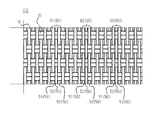
- the number of warp yarns 10 in the region R2 between the first barrier portion 30m and the second barrier portion 30n shown in FIG. Less than the number of warps 10 in the region R1 and / or the region R3 adjacent to R2.
- the region R1 is a region between the second barrier portion 30n and the fastener element 200.
- the region R3 is a region between the first barrier portion 30m and the side edge portion of the fastener tape 100 where the fastener element 200 is not provided.
- the arrangement density of the warps 10 in the region R2 is smaller than the arrangement density of the warps 10 in the region R1 and / or the region R3.
- the number of warp yarns 10 occupying the unit width in the tape width direction in the region R2 is smaller than the number of warp yarns 10 occupying the same unit width in the tape width direction in the region R1 and / or the region R3.
- the arrangement density of the warps 10 in the region R3 is equal to the arrangement density of the warps 10 in the region R2. In some embodiments, the arrangement density of the warps 10 at the side edge 111 is equal to the arrangement density of the warps 10 in the region R1.
- the inventor of the present application introduces a plurality of heat fusion yarns 50 that are selectively adjacent to a group of warp yarns arranged in the left-right direction when the fastener tape 100 is woven using a loom, contrary to the above-mentioned practice.
- a plurality of the heat fusion yarns 50 arranged adjacent to each other in the tape width direction are partially fused and fixed, and the lateral displacement of the adjacent warp yarns 10 is restricted.
- the significance of constructing the possible barrier portion 30 was found.
- the barrier portion 30 When the barrier portion 30 is formed on the tape main portion 112, the barrier portion 30 is fixed to the weft 20 or the weft set 25 more strongly than the warp 10. Therefore, the displacement of the warp yarn 10 adjacent to the barrier portion 30 in the tape width direction is suitably restricted.
- the warp yarns 10 can be arranged sparsely in either the left or right region of the barrier portion 30 or in both regions.
- the number of heat-sealing yarns 50 introduced into the tape main body 112 is smaller than the number of warp yarns 10 of the non-heat-sealing yarn included in the tape main body 112 of the fastener tape 100.
- the heat-sealing yarn 50 is usually more expensive than the non-heat-sealing warp yarn 10, and stricter temperature control may be required for storage.
- each barrier portion 30 is composed of three heat-sealing yarns 50, and a total of six heat-sealing yarns 50 are used, which increases the manufacturing cost of the fastener tape. It has been avoided.
- the heat-bonding yarn 50, the barrier portion 30, and / or the linear portion exhibit a color different from that of the warp yarn 10.
- design property can be simultaneously provided to the fastener tape 100.
- the heat fusion yarn 50 includes a core and a clad covering the core.
- the core is made of a heat resistant material.
- the cladding includes a heat melting material.
- the heat fusion yarn 50 is a solid linear body made of a heat melting material.
- the warp yarn 10 is formed by twisting a large number of thin yarns. In this case, the heat fusion yarn 50 is less resistant to the needle than the warp yarn 10.
- the heat fusion yarn 50, the barrier portion 30, and / or the linear portion exhibits a different color from the warp yarn 10, otherwise a needle that allows left-right displacement of the warp yarn 10 adjacent to the barrier portion 30. It is possible to reduce the risk of damage to the barrier portion 30 and the linear portion.
- FIG. 5 shows that three sets of adjacent heat-bonding yarn sets 61 to 63 are woven into the tape main body 112 in order to introduce the three barrier portions 30 into the tape main body 112. Even in such a case, the same effect as described above can be obtained.
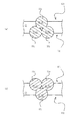
- 6 and 7 show an example in which each barrier portion 30 is composed of two heat-sealing yarns 50. Even in such a case, the same effect as described above can be obtained.
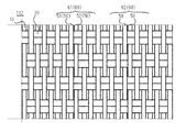
- FIG. 8 shows an example in which one barrier portion 30 formed from two heat-sealing yarns 50 is introduced into the tape main body 112. Even in such a case, the same effect as described above can be obtained.
- FIG. 9 shows an example in which adjacent heat-bonding yarns 50 extend back and forth in different modes. Even in such a case, the same effect as described above can be obtained. Specifically, in FIG. 9, the first heat fusion yarn 51 floats and sinks every two weft sets 25, while the second heat fusion yarn 52 rises and sinks every one weft set 25.
- the upper part of the first heat fusion yarn 51 straddling the weft set 25 on the tape upper surface 101 side and the upper part of the second heat fusion yarn 52 straddling the weft set 25 on the tape upper surface 101 side are also fused and fixed to each other. .
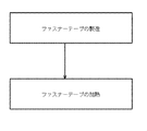
- FIG. 10 shows a method for manufacturing the fastener tape 100.
- the fastener element 200 is a coil element, it is incorporated into the fastener tape 100 when the fastener tape 100 is woven, or is sewn to the side edge 111 of the fastener tape 100 after the fastener tape 100 is woven.
- the fastener element 200 is a resin or metal element, the fastener element 200 is provided on the side edge 111 of the fastener tape 100 by a known method after the fastener tape 100 is woven.
- the method for manufacturing the fastener tape 100 includes a step of manufacturing the fastener tape and a step of heating the fastener tape.
- a fastener element is provided at the side edge of the fastener tape between the step of manufacturing the fastener tape and the step of heating the fastener tape.
- fastener elements are provided on the side edges of the fastener tape.
- the process which manufactures a fastener tape can use the loom currently used widely. By setting the weft and the warp to the loom and operating the loom, the illustrated example of the fastener tape can be manufactured.
- At least a plurality of heat fusion yarns 51 to 53 are supplied as warp yarns 10 adjacent to each other, and warp yarns 10 of non-heat fusion yarns are provided on both sides of the plurality of adjacent heat fusion yarns 51 to 53. Supplied.
- a plurality of additional heat fusing yarns 54-56 are fed adjacently as warp yarn 10, and non-heat fusing yarn warps on either side of the adjacent plurality of heat fusing yarns 54-56. 10 is supplied.
- the heat fusion yarn set 60 includes three heat fusion yarns.
- the first to third heat fusion yarns 51 to 53 are supplied adjacent to each other, and the non-heat fusion yarn warp yarn 10 is supplied on both sides of the first to third heat fusion yarns 51 to 53 arranged adjacent to each other. .
- a plurality of heat fusion yarn sets 60 are supplied.
- the fourth to sixth heat fusion yarns 54 to 56 are supplied adjacent to each other, and the fourth to sixth heat fusion yarns 54 to 56 arranged adjacent to each other are supplied.
- the non-heat-sealed warp yarn 10 is supplied.
- Three or more warp yarns 10 are supplied between the first to third heat fusion yarns 51 to 53 arranged adjacent to each other and the fourth to sixth heat fusion yarns 54 to 56 arranged adjacent to each other.
- the plurality of adjacent heat-sealing yarns 50 are partially fused to form a barrier portion 30 that prevents the displacement of the non-heat-sealing warp yarns 10.
- the heating temperature and the heating time are appropriately set in consideration of the material of the heat fusion yarn, the material of the weft and the warp.
- the first to third heat fusion yarns 51 to 53 are partially fixed to each other.
- the first connection portion 51b of the first heat fusion yarn 51 and the second connection portion 52d of the second heat fusion yarn 52 are fixed.
- the second connecting portion 51d of the first heat-sealing yarn 51 and the first connecting portion 52b of the second heat-sealing yarn 52 are fixed.
- the first connection portion 52b of the second heat fusion yarn 52 and the second connection portion 53d of the third heat fusion yarn 53 are fixed.
- the second connecting portion 52d of the second heat-sealing yarn 52 and the first connecting portion 53b of the third heat-sealing yarn 53 are fixed. Regarding the adjacent first heat fusion yarn 51 and third heat fusion yarn 53, the first connection portion 51b of the first heat fusion yarn 51 and the first connection portion 53b of the third heat fusion yarn 53 are fixed. The second connecting portion 51d of the first heat-sealing yarn 51 and the second connecting portion 53d of the third heat-sealing yarn 53 are fixed. Similarly, the fourth to sixth heat fusion yarns 54 to 56 are partially fixed to each other.
- the first and second heat fusion yarns 51 and 52 are partially fixed to each other.
- the first connection portion 51b of the first heat fusion yarn 51 and the second connection portion 52d of the second heat fusion yarn 52 are fixed.
- the second connecting portion 51d of the first heat-sealing yarn 51 and the first connecting portion 52b of the second heat-sealing yarn 52 are fixed.
- FIG. 11 shows an example in which a coil element as an example of a fastener element is woven into a fastener tape.
- the leg portions of the coil element 200 are fastened by a plurality of warps 10, and the side edges 111 of the fastener tape 100 are woven by the double pick wefts 20.
- the above-described steps or operations are performed so that the engaging head of the coil element 200 protrudes from the side edge portion 111.
- the coil element 200 is woven into the fastener tape 100 with one pick and one element.
- One element described here means one element of the coil element 200.
- the density of the wefts 20 in the fastener tape 100 is reduced, and the crossing density of the warp yarns 10 and the weft yarns 20 is also reduced. There is a risk.
- one or more barrier portions 30 are provided in the fastener tape 100, and it is possible to effectively cope with such a case.
- the upper and lower legs of one element of the coil element 200 are arranged between the weft sets 25 adjacent in the front-rear direction.
- the upper leg portion and the lower leg portion are coupled to each other via an engagement head that is formed to be wide on the left and right inner sides.
- An upper leg portion of an element is coupled to a lower leg portion of an adjacent element through a folded portion.
- the coil element 200 is constructed by a series of such basic elements.
Landscapes
- Woven Fabrics (AREA)
- Slide Fasteners (AREA)
Abstract
A fastener tape (100) has tape top and bottom surfaces (101, 102). The fastener tape (100) includes a tape main portion (112) that includes a structure in which warps (10) and wefts (20) are woven. The tape main portion (112) extends in the direction in which the warps (10) extend, and includes at least one barrier portion (30) that restrains the displacement of adjacent warps (10) on both sides of the barrier portion (30). The barrier portion (30) includes at least a first linear portion (31) that extends so as to alternately appear on the tape top and bottom surfaces (101, 102), and a second linear portion (32) that extends so as to alternately appear on the tape top and bottom surfaces (101, 102). The first linear portion (31) and the second linear portion (32) are partially fixed to each other.
Description
本開示は、ファスナーテープ及びファスナーテープの製造方法に関する。
The present disclosure relates to a fastener tape and a method for manufacturing the fastener tape.
特許文献1には、テープ主体部をメッシュ状の組織とするため、表面が合成樹脂によりコーティングされた糸を経糸又は緯糸として用いることが開示されている。
Patent Document 1 discloses that a thread whose surface is coated with a synthetic resin is used as a warp or a weft so that the tape main part has a mesh-like structure.
ファスナーテープのしっかりとした織り組織を構築するため、ファスナーテープの所定左右幅について所定本数の経糸が用いられる。しかしながら、この場合、ファスナーテープの高い製造効率を達成し難く、ファスナーテープの重量が増加し、またファスナーテープの原価が増加してしまう。他方、ファスナーテープにおける経糸の本数を減じることは、ファスナーテープ幅方向において経糸のズレが生じさせるため、現実的に有効な選択肢として殆ど検討されていない。
In order to build a firm weave structure of the fastener tape, a predetermined number of warps are used for a predetermined width of the fastener tape. However, in this case, it is difficult to achieve high production efficiency of the fastener tape, the weight of the fastener tape is increased, and the cost of the fastener tape is increased. On the other hand, reducing the number of warp yarns in the fastener tape causes warp misalignment in the width direction of the fastener tape, and is hardly studied as a practically effective option.
本開示の一態様に係るファスナーテープは、テープ上面及び下面(101、102)を有するファスナーテープ(100)であって、
経糸(10)と緯糸(20)が織られた組織を含むテープ主体部(112)を含み、
前記テープ主体部(112)は、経糸(10)が延びる方向に沿って延び、両側で隣接する経糸(10)の変位を規制する1以上の障壁部(30)を含み、
前記障壁部(30)は、少なくとも、前記テープ上面及び下面(101、102)に交互に現れるように延びる第1線状部(31)と、前記テープ上面及び下面(101、102)に交互に現れるように延びる第2線状部(32)を含み、前記第1線状部(31)と前記第2線状部(32)が部分的に固着している。 The fastener tape according to one aspect of the present disclosure is a fastener tape (100) having a tape upper surface and a lower surface (101, 102),
Including a tape main part (112) including a structure in which the warp (10) and the weft (20) are woven;
The tape main body portion (112) includes one or more barrier portions (30) that extend along the direction in which the warp yarn (10) extends and restrict displacement of the adjacent warp yarns (10) on both sides,
The barrier portions (30) are alternately arranged at least on the first linear portions (31) extending so as to appear alternately on the upper and lower surfaces (101, 102) of the tape and on the upper and lower surfaces (101, 102) of the tape. The first linear portion (31) and the second linear portion (32) are partially fixed, including the second linear portion (32) extending so as to appear.
幾つかの実施形態においては、前記第1及び第2線状部(31、32)は、各々、
前記テープ下面(102)において緯糸(20)を跨ぐ下部(31a、32a)と、
前記テープ上面(101)において緯糸(20)を跨ぐ上部(31c、32c)と、
前記下部(31a、32a)と前記上部(31c、32c)を連結し、前記テープ下面側から前記テープ上面側に延びる第1連結部(31b、32b)と、
前記下部(31a、32a)と前記上部(31c、32c)を連結し、前記テープ上面側から前記テープ下面側に延びる第2連結部(31d、32d)を含み、
前記第1線状部(31)の前記第1連結部(31b)と前記第2線状部(32)の前記第2連結部(32d)が固着し、前記第1線状部(31)の前記第2連結部(31d)と前記第2線状部(32)の前記第1連結部(32b)が固着する。 In some embodiments, the first and second linear portions (31, 32) are each
Lower portions (31a, 32a) straddling the weft yarn (20) on the tape lower surface (102);
Upper portions (31c, 32c) straddling the weft yarn (20) on the tape upper surface (101);
A first connecting part (31b, 32b) that connects the lower part (31a, 32a) and the upper part (31c, 32c) and extends from the tape lower surface side to the tape upper surface side;
The lower part (31a, 32a) and the upper part (31c, 32c) are connected, and includes a second connecting part (31d, 32d) extending from the tape upper surface side to the tape lower surface side,
The first connecting portion (31b) of the first linear portion (31) and the second connecting portion (32d) of the second linear portion (32) are fixed, and the first linear portion (31). The second connecting portion (31d) and the first connecting portion (32b) of the second linear portion (32) adhere to each other.
幾つかの実施形態においては、ファスナーテープ(100)が存在する平面において経糸(10)が延びる方向をテープ長さ方向とし、経糸(10)が延びる方向に直交する方向をテープ幅方向とする。前記第1及び第2線状部(31、32)は、テープ上面及び下面(101、102)のいずれかにおいて、テープ幅方向に延びる2本の緯糸部分を含む緯糸組(25)を交互に跨ぐように延びる。
In some embodiments, the direction in which the warp (10) extends in the plane on which the fastener tape (100) exists is the tape length direction, and the direction orthogonal to the direction in which the warp (10) extends is the tape width direction. The first and second linear portions (31, 32) alternately form a weft group (25) including two weft portions extending in the tape width direction on either the upper surface or the lower surface (101, 102) of the tape. It extends to straddle.
幾つかの実施形態においては、前記テープ主体部(112)が複数の障壁部(30)を含む。前記複数の障壁部(30)は、第1及び第2障壁部(30m、30n)を含み、
前記第1及び第2障壁部(30m、30n)の間には複数の経糸(10)が設けられ、前記複数の経糸(10)は、隣接するいずれの経糸(10)にも固着しない経糸(10)を含む。 In some embodiments, the tape main body (112) includes a plurality of barrier portions (30). The plurality of barrier portions (30) include first and second barrier portions (30m, 30n),
A plurality of warps (10) are provided between the first and second barrier portions (30m, 30n), and the plurality of warps (10) are warps that do not adhere to any adjacent warps (10) ( 10).
幾つかの実施形態においては、前記第1及び第2障壁部(30m、30n)の間には少なくとも3本の前記複数の経糸(10)が在る。
In some embodiments, there are at least three of the plurality of warps (10) between the first and second barrier portions (30m, 30n).
幾つかの実施形態においては、前記第1及び第2障壁部(30m、30n)の間における前記複数の経糸(10)の配列密度は、前記テープ主体部(112)の1以上の他の部分(R1、R3)よりも小さい。
In some embodiments, the arrangement density of the plurality of warps (10) between the first and second barrier portions (30m, 30n) is one or more other portions of the tape main portion (112). Smaller than (R1, R3).
幾つかの実施形態においては、前記第1及び第2障壁部(30m、30n)の間における前記複数の経糸(10)の本数は、前記テープ主体部(112)の1以上の他の部分(R1、R3)における前記複数の経糸(10)の本数よりも少ない。
In some embodiments, the number of the plurality of warps (10) between the first and second barrier portions (30m, 30n) is one or more other portions of the tape main portion (112) ( Less than the number of the plurality of warps (10) in R1, R3).
幾つかの実施形態においては、前記障壁部(30)は、前記テープ上面及び下面(101、102)に交互に現れるように延びる第3線状部(33)を更に含み、前記第3線状部(33)は、前記第1及び第2線状部(31、32)の少なくとも一方に対して部分的に固着する。
In some embodiments, the barrier portion (30) further includes a third linear portion (33) extending so as to appear alternately on the upper surface and the lower surface (101, 102) of the tape, and the third linear shape. The part (33) is partially fixed to at least one of the first and second linear parts (31, 32).
本開示の別側面に係るファスナーテープの製造方法は、緯糸(20)及び経糸(10)を供給し、テープ上面及び下面(101,102)を有するファスナーテープ(100)を製造する第1工程であって、少なくとも複数の熱融着糸(51、52、53)が経糸(10)として隣接して供給され、この隣接した複数の熱融着糸(51、52、53)の両側において非熱融着糸の経糸(10)が供給される、第1工程と、
前記ファスナーテープ(100)を加熱する第2工程であって、前記隣接した複数の熱融着糸(51、52、53)が部分的に融着し、前記非熱融着糸の経糸(10)の変位を阻止する障壁部(30)を形成する、第2工程を含む。 The method for manufacturing a fastener tape according to another aspect of the present disclosure includes a first step of supplying a weft thread (20) and a warp thread (10) to manufacture a fastener tape (100) having an upper surface and a lower surface (101, 102) of the tape. At least a plurality of heat fusion yarns (51, 52, 53) are supplied adjacently as warp yarns (10), and non-heat is applied to both sides of the plurality of adjacent heat fusion yarns (51, 52, 53). A first step in which a warp yarn (10) of the fused yarn is supplied;
In the second step of heating the fastener tape (100), the plurality of adjacent heat fusion yarns (51, 52, 53) are partially fused, and the warp yarns (10 A second step of forming a barrier portion (30) that prevents the displacement of.
幾つかの実施形態においては、前記第1工程において、追加の複数の熱融着糸(54、55、56)が経糸(10)として隣接して供給され、この隣接した追加の複数の熱融着糸(54、55、56)の両側において非熱融着糸の経糸(10)が供給される。
In some embodiments, in the first step, an additional plurality of heat fusion yarns (54, 55, 56) are supplied adjacently as warp yarns (10), and the adjacent additional heat fusion yarns are provided. A warp yarn (10) of a non-heat-sealing yarn is supplied on both sides of the yarn (54, 55, 56).
幾つかの実施形態においては、前記第1工程において、前記隣接した複数の熱融着糸(51、52、53)と前記追加の隣接した複数の熱融着糸(54、55、56)の間には少なくとも3本の経糸(10)が供給される。
In some embodiments, in the first step, the plurality of adjacent thermal fusion yarns (51, 52, 53) and the additional adjacent thermal fusion yarns (54, 55, 56). In between, at least three warps (10) are supplied.
幾つかの実施形態においては、前記第2工程において加熱される前記ファスナーテープ(100)に含まれる前記複数の熱融着糸(51、52、53)は、各々、
前記テープ下面(102)において緯糸(20)を跨ぐ下部(51a、52a、53a)と、
前記テープ上面(101)において緯糸(20)を跨ぐ上部(51c、52c、53c)と、
前記下部(51a、52a、53a)と前記上部(51c、52c、53c)を連結し、前記テープ下面(102)側から前記テープ上面(101)側に延びる第1連結部(31b、32b)と、
前記下部(51a、52a、53a)と前記上部(51c、52c、53c)を連結し、前記テープ上面(101)側から前記テープ下面(102)側に延びる第2連結部(31d、32d)を含み、
前記第2工程により、複数の熱融着糸(51、52、53)に含まれる第1熱融着糸(51)の第1連結部(51b)と複数の熱融着糸(51、52、53)に含まれる第2熱融着糸(52)の第2連結部(52d)が融着し、前記第1熱融着糸(51)の第2連結部(51d)と前記第2熱融着糸(52)の第1連結部(52b)が融着する。 In some embodiments, the plurality of heat fusion yarns (51, 52, 53) included in the fastener tape (100) heated in the second step are each
A lower portion (51a, 52a, 53a) straddling the weft (20) on the lower surface (102) of the tape;
An upper portion (51c, 52c, 53c) straddling the weft (20) on the upper surface (101) of the tape;
A first connecting portion (31b, 32b) that connects the lower portion (51a, 52a, 53a) and the upper portion (51c, 52c, 53c) and extends from the tape lower surface (102) side to the tape upper surface (101) side; ,
A second connecting portion (31d, 32d) that connects the lower portion (51a, 52a, 53a) and the upper portion (51c, 52c, 53c) and extends from the tape upper surface (101) side to the tape lower surface (102) side. Including
By the second step, the first connecting portion (51b) of the first heat-sealing yarn (51) and the plurality of heat-sealing yarns (51, 52) included in the plurality of heat-sealing yarns (51, 52, 53). 53), the second connecting portion (52d) of the second heat-sealing yarn (52) is fused, and the second connecting portion (51d) of the first heat-sealing yarn (51) and the second connecting portion (52d). The first connecting portion (52b) of the heat-sealing yarn (52) is fused.
本開示の一態様によれば、テープ主体部の障壁部によりその両側の経糸の変位を阻止できる。
According to one aspect of the present disclosure, the warp on both sides can be prevented from being displaced by the barrier portion of the tape main body.
以下、図1乃至図10を参照しつつ、本発明の非限定の例示の実施形態について説明する。開示の1以上の実施形態及び実施形態に包含される各特徴は、個々に独立したものではない。当業者は、過剰説明を要せず、各実施形態及び/又は各特徴を組み合わせることができる。当業者は、そのような組み合わせによる相乗効果も理解可能である。実施形態間の重複説明は、原則的に省略する。参照図面は、発明の記述を主たる目的とするものであり、作図の便宜のために簡略化されている場合がある。
Hereinafter, non-limiting exemplary embodiments of the present invention will be described with reference to FIGS. 1 to 10. Each feature included in one or more disclosed embodiments and embodiments is not individually independent. Those skilled in the art can combine the embodiments and / or features without undue explanation. Those skilled in the art can also understand the synergistic effects of such combinations. In principle, duplicate descriptions between the embodiments are omitted. The reference drawings are mainly for description of the invention, and may be simplified for convenience of drawing.
図1に示すスライドファスナー500は、左右一対のファスナーストリンガー300と、左右一対のファスナーストリンガー300を開閉するための一つのスライダー400を含む。各ファスナーストリンガー300は、ファスナーテープ100と、ファスナーテープ100の側縁部111に設けられたファスナーエレメント200を含む。ファスナーエレメント200に隣接して前止め210と後止め220が設けられる。幾つかの実施形態においては、前止め210及び後止め220の一方又は両方が省略される。
1 includes a pair of left and right fastener stringers 300 and a single slider 400 for opening and closing the pair of left and right fastener stringers 300. The slide fastener 500 shown in FIG. Each fastener stringer 300 includes a fastener tape 100 and a fastener element 200 provided on the side edge 111 of the fastener tape 100. A front stop 210 and a rear stop 220 are provided adjacent to the fastener element 200. In some embodiments, one or both of the front stop 210 and the rear stop 220 are omitted.
前後方向は、スライダー400の移動方向を基準として理解される。スライダー400の前進により左右のファスナーストリンガー300が閉じられ、左右のファスナーエレメント200が噛み合う。スライダー400の後進により左右のファスナーストリンガー300が開けられ、左右のファスナーエレメント200が非噛み合いになる。左右方向は、前後方向に直交する方向の一つであり、ファスナーテープ100のテープ面に関して平行である。上下方向は、前後方向に直交する方向の他の一つであり、ファスナーテープ100のテープ面に関して直交する。
The front-rear direction is understood with reference to the moving direction of the slider 400. As the slider 400 advances, the left and right fastener stringers 300 are closed, and the left and right fastener elements 200 are engaged. When the slider 400 moves backward, the left and right fastener stringers 300 are opened, and the left and right fastener elements 200 are disengaged. The left-right direction is one of the directions orthogonal to the front-rear direction, and is parallel to the tape surface of the fastener tape 100. The vertical direction is another one of the directions orthogonal to the front-rear direction, and is orthogonal to the tape surface of the fastener tape 100.
ファスナーテープ100は、テープ上面及び下面101、102を有し、これらによりファスナーテープ100の大凡の厚みが規定される。なお、テープ上面及び下面101、102は、便宜上、命名したものである。テープ上面101は、必ずしもスライダー400の上翼板410が存在する側に在る必要はない。テープ下面102は、必ずしもスライダー400の下翼板がある側に在る必要はない。
The fastener tape 100 has a tape upper surface and a lower surface 101, 102, and the approximate thickness of the fastener tape 100 is defined by these. Note that the upper and lower surfaces 101 and 102 of the tape are named for convenience. The tape upper surface 101 does not necessarily have to be on the side where the upper blade 410 of the slider 400 exists. The tape lower surface 102 does not necessarily have to be on the side where the lower wing plate of the slider 400 exists.
左右一方のファスナーストリンガー300のファスナーテープ100は、左右他方のファスナーストリンガー300のファスナーテープ100に対向する側縁部111を有する。幾つかの場合、側縁部111には芯紐が設けられる。ファスナーテープ100は、側縁部111に隣接してテープ主体部112を有する。ファスナーテープ100の側縁部111は、テープ主体部112に対して左右方向内側に設けられる。テープ主体部112は、側縁部111に対して左右方向外側に設けられる。なお、左右方向内側は、左右方向においてあるファスナーストリンガー300のファスナーテープ100のテープ主体部112上の点又は位置から側縁部111上の点又は位置に向かう方向である。左右方向外側は、左右方向内側の反対に向かう方向である。
The fastener tape 100 of the left and right fastener stringer 300 has a side edge portion 111 that faces the fastener tape 100 of the other left and right fastener stringer 300. In some cases, the side edge 111 is provided with a core string. The fastener tape 100 has a tape main body 112 adjacent to the side edge portion 111. The side edge 111 of the fastener tape 100 is provided on the inner side in the left-right direction with respect to the tape main body 112. The tape main body 112 is provided on the outer side in the left-right direction with respect to the side edge 111. The inner side in the left-right direction is a direction from a point or position on the tape main portion 112 of the fastener tape 100 of the fastener stringer 300 in the left-right direction to a point or position on the side edge 111. The outer side in the left-right direction is the direction opposite to the inner side in the left-right direction.
ファスナーエレメント200は、図示例においては、モノフィラメントがらせん状に巻かれたコイルエレメントである。しかしながら、他の形態においては、ファスナーエレメント200は、ブロック状の樹脂エレメントが前後方向に一定間隔で配置されたエレメント列を含み、若しくは金属エレメントが前後方向に一定間隔で配置されたエレメント列を含む。様々な実施形態において様々な種類のファスナーエレメントが用いられ得る。
The fastener element 200 is a coil element in which a monofilament is spirally wound in the illustrated example. However, in other forms, the fastener element 200 includes an element row in which block-shaped resin elements are arranged at regular intervals in the front-rear direction, or an element row in which metal elements are arranged at regular intervals in the front-rear direction. . Various types of fastener elements may be used in various embodiments.
図示例のファスナーエレメント200は、前後方向に沿って単位構造が連続した構成を含む。単位構造は、ファスナーテープ100の側縁部111よりも左右方向内側に配される係合頭部、係合頭部の上端に連結して左右方向外側に延びる上部脚部、係合頭部の下端に連結して左右方向外側に延びる下部脚部、及びこの下部脚部の左右方向外側の端部を隣接する基本単位の上部脚部の左右方向外側の端部に結合するように湾曲した反転部を含む。左右のファスナーエレメント200が噛み合う仕組みについては当業者に広く知られており、説明を省略する。
The illustrated fastener element 200 includes a configuration in which unit structures are continuous along the front-rear direction. The unit structure includes an engaging head disposed on the inner side in the left-right direction than the side edge portion 111 of the fastener tape 100, an upper leg portion connected to the upper end of the engaging head and extending outward in the left-right direction, A lower leg connected to the lower end and extending outward in the left-right direction, and an inversion curved so as to join the outer end in the left-right direction of the lower leg to the outer end in the left-right direction of the upper leg of the adjacent basic unit Part. The mechanism by which the left and right fastener elements 200 mesh with each other is widely known to those skilled in the art and will not be described.
スライダー400は、図示例においては、上翼板410と、下翼板、上翼板と下翼板を連結する連結柱、上翼板410の上面に設けられる引手取付柱440、及び引手取付柱440に取り付けられた引手450を有するスライダーの一つである。ユーザーが引手450を把持してスライダー400を前進させると、左右のファスナーエレメント200が左右の前口を介してスライダー400内に進入し、スライダー400の連結柱を通過するに際してお互いに係合する。スライダー400の更なる前進により噛み合い状態の左右のファスナーエレメント200がスライダー400の後口を介してスライダー400の内部から外部に出る。様々な実施形態において様々な種類のスライダーが用いられ得る。
In the illustrated example, the slider 400 includes an upper wing plate 410, a lower wing plate, a connecting column that connects the upper wing plate and the lower wing plate, a pulling attachment column 440 provided on the upper surface of the upper wing plate 410, and a pulling attachment column. One of the sliders having a handle 450 attached to 440. When the user holds the handle 450 and moves the slider 400 forward, the left and right fastener elements 200 enter the slider 400 via the left and right front ports and engage with each other when passing through the connecting column of the slider 400. As the slider 400 further advances, the left and right fastener elements 200 engaged with each other come out from the inside of the slider 400 through the rear opening of the slider 400. Various types of sliders can be used in various embodiments.
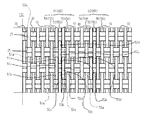
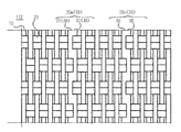
図1及び図2に示すように、ファスナーテープ100は、前後方向に延びる経糸10と左右方向に延びる緯糸20が織られた組織を含むものである。ファスナーテープ100は、前後方向に延びる経糸10と左右方向に延びる緯糸20が織られた組織を含むテープ主体部112を含む。図1に示すように、ファスナーテープ100は左右幅W100を有し、前後長L100を有し、W100<L100を満足する。側縁部111は左右幅W111を有し、テープ主体部112は左右幅W112を有し、W111<W112を満足する。
1 and 2, the fastener tape 100 includes a structure in which warp yarns 10 extending in the front-rear direction and weft yarns 20 extending in the left-right direction are woven. The fastener tape 100 includes a tape main body 112 including a structure in which warps 10 extending in the front-rear direction and wefts 20 extending in the left-right direction are woven. As shown in FIG. 1, the fastener tape 100 has a lateral width W100, a longitudinal length L100, and satisfies W100 <L100. The side edge portion 111 has a left-right width W111, and the tape main body portion 112 has a left-right width W112, which satisfies W111 <W112.
ファスナーテープ100が存在する平面において経糸10が延びる方向をテープ長さ方向とし、経糸10が延びる方向に直交する方向をテープ幅方向とする。適切又は必要であれば、本明細書で参照される前後方向をテープ長さ方向で読み替え、左右方向がテープ幅方向で読み替えて本明細書の開示内容が理解される。これらの逆の読み替えも同様に可能である。
The direction in which the warp 10 extends in the plane on which the fastener tape 100 exists is the tape length direction, and the direction perpendicular to the direction in which the warp 10 extends is the tape width direction. If appropriate or necessary, the front-rear direction referred to in the present specification is read in the tape length direction, and the left-right direction is read in the tape width direction to understand the disclosure of the present specification. These reverse readings are also possible.
本実施形態においては、テープ主体部112が1以上の障壁部30を含む。障壁部30は、経糸10が延びる方向、つまりテープ長さ方向に沿って延び、テープ幅方向において隣接する経糸10の変位を規制する。障壁部30に隣接して配される複数の経糸10は、隣接するいずれの経糸10にも固着しない経糸10を含む。障壁部30は、経糸10と緯糸20の組織に組み込まれるものとも言える。テープ主体部112に設けられる障壁部30の個数は図示例に限定されるものではない。実施形態によっては、テープ主体部112に1、2、3、4、5、6、7、又は8以上の障壁部30が設けられる。
In the present embodiment, the tape main body 112 includes one or more barrier portions 30. The barrier portion 30 extends in the direction in which the warp yarn 10 extends, that is, in the tape length direction, and regulates the displacement of the adjacent warp yarns 10 in the tape width direction. The plurality of warp yarns 10 arranged adjacent to the barrier portion 30 include warp yarns 10 that do not adhere to any adjacent warp yarns 10. It can be said that the barrier portion 30 is incorporated in the structure of the warp 10 and the weft 20. The number of the barrier portions 30 provided in the tape main body 112 is not limited to the illustrated example. In some embodiments, the tape main body 112 is provided with 1, 2, 3, 4, 5, 6, 7, or 8 or more barrier portions 30.
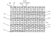
図1及び図3の図示例では、2つの障壁部として第1及び第2障壁部30m、30nが設けられる。第1及び第2障壁部30m、30nは、テープ幅方向において一定の間隔を維持しながらテープ長さ方向に平行に延びる。各障壁部は、テープ長さ方向に線状に延びる。従って、各障壁部を線状障壁と呼んでも構わない。
1 and 3, first and second barrier portions 30m and 30n are provided as two barrier portions. The first and second barrier portions 30m and 30n extend in parallel to the tape length direction while maintaining a constant interval in the tape width direction. Each barrier portion extends linearly in the tape length direction. Therefore, each barrier portion may be called a linear barrier.
なお、図1に示す場合、オプションとして3つ目の障壁部として第3障壁部30rが設けられる。第3障壁部30rは、ファスナーエレメント200の近傍に配される。ファスナーエレメント200の近傍では、スライダー400とファスナーテープ100の接触が生じ、経糸10がズレ易い。ファスナーエレメント200の近傍への上述の第3障壁部30rの配備により、かかる問題が回避又は低減され、ファスナーテープ100の耐久性が高められる。
In the case shown in FIG. 1, a third barrier portion 30r is optionally provided as a third barrier portion. The third barrier portion 30r is disposed in the vicinity of the fastener element 200. In the vicinity of the fastener element 200, contact between the slider 400 and the fastener tape 100 occurs, and the warp yarn 10 is easily displaced. By providing the above-described third barrier portion 30r in the vicinity of the fastener element 200, such a problem is avoided or reduced, and the durability of the fastener tape 100 is enhanced.
障壁部30は、テープ幅方向においてその左右に隣接する経糸10の変位を規制する。従って、少なくとも障壁部30に隣接する範囲において経糸10の配列間隔を広く確保することが許容される。より減じられた本数の経糸10でファスナーテープ100を織成することが許容され、ファスナーテープ100の製造効率が高められ、若しくはファスナーテープ100の重量が減じられ、若しくはファスナーテープ100の原価を低減でき、若しくはこれら全てが達成される。
The barrier portion 30 regulates the displacement of the warp yarn 10 adjacent to the left and right in the tape width direction. Therefore, it is allowed to secure a wide arrangement interval of the warps 10 at least in a range adjacent to the barrier portion 30. It is allowed to weave the fastener tape 100 with the reduced number of warps 10, the manufacturing efficiency of the fastener tape 100 can be increased, the weight of the fastener tape 100 can be reduced, or the cost of the fastener tape 100 can be reduced. Or all of this is achieved.
障壁部30は、テープ主体部112において左右に隣接した熱融着糸50をテープ長さ方向に沿って複数箇所で融着することにより構築される。一つの障壁部30を形成するために用いられる熱融着糸50の個数は図示例に限定されるべきではない。実施形態によっては、一つの障壁部30を形成するために1、2、3、4、5、6、7、又は8本以上の熱融着糸50が用いられる。経糸10として熱融着糸を用いて織成されたファスナーテープ100を加熱すると、隣接する熱融着糸の部分がお互いに融着し、その結果、隣接する熱融着糸の部分的な固着が達成される。
The barrier portion 30 is constructed by fusing the heat fusion yarns 50 adjacent to the left and right in the tape main body portion 112 at a plurality of locations along the tape length direction. The number of heat fusion yarns 50 used to form one barrier portion 30 should not be limited to the illustrated example. Depending on the embodiment, one, two, three, four, five, six, seven, or eight or more thermal fusing yarns 50 are used to form one barrier portion 30. When the fastener tape 100 woven using the heat fusion yarn as the warp yarn 10 is heated, the adjacent heat fusion yarn portions are fused to each other, and as a result, the adjacent heat fusion yarn is partially fixed. Is achieved.
図2に示すように、テープ主体部112は、経糸10と緯糸20が交差して構成される。テープ主体部112は、テープ幅方向に左右に延びる緯糸20が前後に隣接して配置された緯糸組25を含む。各緯糸組25は、テープ幅方向に延びる2本の緯糸部分を含み、端的には、前側緯糸部と後側緯糸部を含む。前後に配された緯糸組25に関して、後方の緯糸組25に含まれる前側緯糸部の左右方向外側の端部は、前方の緯糸組25に含まれる後側緯糸部の左右方向外側の端部に不図示の折返し部を介して結合される。
As shown in FIG. 2, the tape main body 112 is configured by intersecting the warp 10 and the weft 20. The tape main body 112 includes a weft set 25 in which wefts 20 extending left and right in the tape width direction are arranged adjacent to each other in the front-rear direction. Each weft set 25 includes two weft portions extending in the tape width direction, and ends with a front weft portion and a rear weft portion. With respect to the weft sets 25 arranged at the front and rear, the left and right outer ends of the front weft portions included in the rear weft set 25 are located at the left and right outer ends of the rear weft portions included in the front weft set 25. It couple | bonds through the folding part not shown.
図2の図示例では、テープ主体部112は、複数の障壁部30を形成するため、複数の熱融着糸組60、端的には第1及び第2熱融着糸組61、62を含む。第1熱融着糸組61は、3本の熱融着糸50を含み、端的には、第1乃至第3熱融着糸51~53を含む。第2熱融着糸組62は、3本の熱融着糸50を含み、端的には、第4乃至第6熱融着糸54~56を含む。他の形態においては、第1熱融着糸組61に含まれる熱融着糸50の本数が、第2熱融着糸組62に含まれる熱融着糸50の本数よりも多い又は少ない。
In the illustrated example of FIG. 2, the tape main body 112 includes a plurality of thermal fusion yarn sets 60, and first and second thermal fusion yarn sets 61 and 62 in order to form a plurality of barrier portions 30. . The first heat-sealing yarn set 61 includes three heat-sealing yarns 50, and ends up including first to third heat-sealing yarns 51 to 53. The second heat fusing yarn set 62 includes three heat fusing yarns 50, and ends up including fourth to sixth heat fusing yarns 54 to 56. In another embodiment, the number of the heat-fusible yarns 50 included in the first heat-fusible yarn set 61 is greater or less than the number of the heat-fusible yarns 50 included in the second heat-welding yarn set 62.
図2の図示例においては、第1熱融着糸51と第2熱融着糸52がテープ幅方向において左右に隣接する。第2熱融着糸52と第3熱融着糸53がテープ幅方向において左右に隣接する。第1熱融着糸51と第3熱融着糸53は、テープ幅方向において第2熱融着糸52を挟んで隣接して配置される。第1乃至第3熱融着糸51~53についてした同様の関係が第4乃至第6熱融着糸54~56についても当てはまる。
In the illustrated example of FIG. 2, the first heat fusion yarn 51 and the second heat fusion yarn 52 are adjacent to each other in the tape width direction. The second heat fusion yarn 52 and the third heat fusion yarn 53 are adjacent to each other in the tape width direction. The first heat fusion yarn 51 and the third heat fusion yarn 53 are arranged adjacent to each other with the second heat fusion yarn 52 interposed therebetween in the tape width direction. The same relationship applied to the first to third heat fusion yarns 51 to 53 applies to the fourth to sixth heat fusion yarns 54 to 56.
必ずしもこの限りではないが、図示例においては、各熱融着糸50は、一つの緯糸組25単位で浮き沈みしながら前後方向に延びる。熱融着糸50が浮くとは、熱融着糸50がテープ下面102側からテープ上面101側に上昇することを意味する。熱融着糸50が沈むとは、熱融着糸50がテープ上面101側からテープ下面102側に下降することを意味する。
Although not necessarily limited to this, in the illustrated example, each heat-sealing yarn 50 extends in the front-rear direction while lifting and sinking in units of 25 weft sets. The fact that the heat fusion yarn 50 is lifted means that the heat fusion yarn 50 rises from the tape lower surface 102 side to the tape upper surface 101 side. The sinking of the thermal fusion yarn 50 means that the thermal fusion yarn 50 descends from the tape upper surface 101 side to the tape lower surface 102 side.
図示例においては、隣接する2つの熱融着糸50の前後方向の延在態様は非同一である。例えば、同一の緯糸組25に関して、第1熱融着糸51がテープ上面101側でそれを跨ぐ時、第2熱融着糸52がテープ下面102側でそれを跨ぐ。同一の緯糸組25に関して、第1熱融着糸51がテープ下面102側でそれを跨ぐ時、第2熱融着糸52がテープ上面101側でそれを跨ぐ。なお、このように隣接する2つの熱融着糸50が相補的に浮き沈みする必要は必ずしもないことに留意されたい。
In the illustrated example, the extending modes in the front-rear direction of the two adjacent heat-bonding yarns 50 are not the same. For example, for the same weft set 25, when the first heat-sealing yarn 51 straddles it on the tape upper surface 101 side, the second heat-sealing yarn 52 straddles it on the tape lower surface 102 side. With respect to the same weft set 25, when the first heat fusion yarn 51 straddles it on the tape lower surface 102 side, the second heat fusion yarn 52 straddles it on the tape upper surface 101 side. It should be noted that it is not always necessary for the two adjacent heat-bonding yarns 50 to rise and fall in a complementary manner.
図示例においては、隣接する2つの熱融着糸50が相補的に浮き沈みするため、第1熱融着糸51及び第2熱融着糸52は、テープ上面101に交互に現れるように延び、同様にテープ下面102に交互に現れるように延びる。第2熱融着糸52及び第3熱融着糸53は、テープ上面101に交互に現れるように延び、同様にテープ下面102に交互に現れるように延びる。第1熱融着糸51と第3熱融着糸53は、同調して浮き沈みするため、第1熱融着糸51と第3熱融着糸53は、テープ上面101面に一緒に現れるように延び、同様にテープ下面102に一緒に現れるように延びる。
In the illustrated example, since the two adjacent heat fusion yarns 50 are complementarily raised and lowered, the first heat fusion yarn 51 and the second heat fusion yarn 52 extend so as to appear alternately on the upper surface 101 of the tape, Similarly, it extends so as to appear alternately on the lower surface 102 of the tape. The second heat fusion yarn 52 and the third heat fusion yarn 53 extend so as to alternately appear on the tape upper surface 101 and similarly extend so as to appear alternately on the tape lower surface 102. Since the first heat fusion yarn 51 and the third heat fusion yarn 53 rise and fall in synchronization, the first heat fusion yarn 51 and the third heat fusion yarn 53 appear together on the upper surface 101 of the tape. And so as to appear together on the lower surface 102 of the tape.
図2の図示例において、第1乃至第3熱融着糸51~53が配置された領域を第1熱融着糸配置領域と呼び、第4乃至第6熱融着糸54~56が配置された領域を第2熱融着糸配置領域と呼んでも良い。幾つかの実施形態においては、第3熱融着糸53と第4熱融着糸54の間には3本以上の経糸10が配される。これら3本以上の各経糸10は、隣接する一方又は両方の経糸10に対して固着しない。図示例においては、第3熱融着糸53と第4熱融着糸54の間には5本の経糸10が配される。これら5本の各経糸10は、隣接する一方又は両方の経糸10に対して固着しない。第1熱融着糸51の第2熱融着糸52と反対側及び、第6熱融着糸56の第5熱融着糸55と反対側には、複数の経糸10が配される。
In the illustrated example of FIG. 2, the region where the first to third heat fusion yarns 51 to 53 are arranged is called a first heat fusion yarn arrangement region, and the fourth to sixth heat fusion yarns 54 to 56 are arranged. This area may be referred to as a second heat fusion yarn arrangement area. In some embodiments, three or more warp yarns 10 are arranged between the third heat fusion yarn 53 and the fourth heat fusion yarn 54. These three or more warps 10 do not adhere to one or both adjacent warps 10. In the illustrated example, five warp yarns 10 are arranged between the third heat fusion yarn 53 and the fourth heat fusion yarn 54. Each of these five warps 10 does not adhere to one or both adjacent warps 10. A plurality of warp yarns 10 are arranged on the opposite side of the first thermal fusion yarn 51 to the second thermal fusion yarn 52 and the opposite side of the sixth thermal fusion yarn 56 to the fifth thermal fusion yarn 55.
第1熱融着糸51は、テープ下面102側で緯糸組25を跨ぐ下部51aと、テープ上面101側で緯糸組25を跨ぐ上部51cと、下部51aと上部51cを連結し、テープ下面102側からテープ上面101側に前側に向けて延びる第1連結部51bと、下部51aと上部51cを連結し、テープ上面101側からテープ下面102側に前側に向けて延びる第2連結部51dを含む。第1熱融着糸51は、これらの部分51a~51dの単位構造が前後方向に連続して成る。
The first heat-sealing yarn 51 connects the lower portion 51a straddling the weft assembly 25 on the tape lower surface 102 side, the upper portion 51c straddling the weft assembly 25 on the tape upper surface 101 side, and the lower portion 51a and the upper portion 51c. A first connecting portion 51b extending from the tape upper surface 101 toward the front side, a lower portion 51a and an upper portion 51c, and a second connecting portion 51d extending from the tape upper surface 101 side toward the tape lower surface 102 toward the front side. The first heat-fusible yarn 51 has a unit structure of these portions 51a to 51d continuously in the front-rear direction.
第2熱融着糸52は、テープ下面102側で緯糸組25を跨ぐ下部52aと、テープ上面101側で緯糸組25を跨ぐ上部52cと、下部52aと上部52cを連結し、テープ下面102側からテープ上面101側に前側に向けて延びる第1連結部52bと、下部52aと上部52cを連結し、テープ上面101側からテープ下面102側に前側に向けて延びる第2連結部52dを含む。第2熱融着糸52は、これらの部分52a~52dの単位構造が前後方向に連続して成る。
The second heat-sealing yarn 52 connects the lower portion 52a straddling the weft assembly 25 on the tape lower surface 102 side, the upper portion 52c straddling the weft assembly 25 on the tape upper surface 101 side, and the lower portion 52a and the upper portion 52c. A first connecting portion 52b extending from the tape upper surface 101 toward the front side, a lower portion 52a and an upper portion 52c are connected, and a second connecting portion 52d extending from the tape upper surface 101 side toward the tape lower surface 102 toward the front side is included. The second heat-bonding yarn 52 is composed of the unit structures of these portions 52a to 52d continuously in the front-rear direction.
第3熱融着糸53は、テープ下面102側で緯糸組25を跨ぐ下部53aと、テープ上面101側で緯糸組25を跨ぐ上部53cと、下部53aと上部53cを連結し、テープ下面102側からテープ上面101側に前側に向けて延びる第1連結部53bと、下部53aと上部53cを連結し、テープ上面101側からテープ下面102側に前側に向けて延びる第2連結部53dを含む。第3熱融着糸53は、これらの部分53a~53dの単位構造が前後方向に連続して成る。
The third heat fusion yarn 53 connects the lower portion 53a straddling the weft set 25 on the tape lower surface 102 side, the upper portion 53c straddling the weft set 25 on the tape upper surface 101 side, and the lower portion 53a and the upper portion 53c. A first connecting portion 53b extending from the tape upper surface 101 toward the front side, a lower portion 53a and an upper portion 53c, and a second connecting portion 53d extending from the tape upper surface 101 side toward the tape lower surface 102 toward the front side. The third heat-bonding yarn 53 is composed of the unit structures of these portions 53a to 53d continuously in the front-rear direction.
第1乃至第3熱融着糸51~53についてした説明が、同様に、第4乃至第6熱融着糸54~56に当てはまる。
The description of the first to third heat fusion yarns 51 to 53 applies to the fourth to sixth heat fusion yarns 54 to 56 as well.
第1熱融着糸51の第1連結部51bと第2熱融着糸52の第2連結部52dがテープ幅方向において左右に隣接して配される。同様に、第1熱融着糸51の第2連結部51dと第2熱融着糸52の第1連結部52bがテープ幅方向において左右に隣接して配される。第2熱融着糸52の第1連結部52bと第3熱融着糸53の第2連結部53dがテープ幅方向において左右に隣接して配される。同様に、第2熱融着糸52の第2連結部52dと第3熱融着糸53の第1連結部53bがテープ幅方向において左右に隣接して配される。第2熱融着糸52の第2連結部52dは、第1熱融着糸51の第1連結部51bと第3熱融着糸53の第1連結部53bの間に挟まれる。第2熱融着糸52の第1連結部52bは、第1熱融着糸51の第2連結部51dと第3熱融着糸53の第2連結部53dの間に挟まれる。第1乃至第3熱融着糸51~53についてした同様の関係が第4乃至第6熱融着糸54~56についても当てはまる。
1st connection part 51b of the 1st heat fusion yarn 51 and 2nd connection part 52d of the 2nd heat fusion yarn 52 are arranged adjacent to right and left in the tape width direction. Similarly, the second connecting portion 51d of the first heat-sealing yarn 51 and the first connecting portion 52b of the second heat-sealing yarn 52 are arranged adjacent to each other in the tape width direction. The 1st connection part 52b of the 2nd heat-fusion yarn 52 and the 2nd connection part 53d of the 3rd heat-fusion yarn 53 are distribute | arranged adjacent to right and left in a tape width direction. Similarly, the second connecting portion 52d of the second heat-sealing yarn 52 and the first connecting portion 53b of the third heat-sealing yarn 53 are arranged adjacent to each other in the tape width direction. The second connection portion 52 d of the second heat fusion yarn 52 is sandwiched between the first connection portion 51 b of the first heat fusion yarn 51 and the first connection portion 53 b of the third heat fusion yarn 53. The first connection portion 52 b of the second heat fusion yarn 52 is sandwiched between the second connection portion 51 d of the first heat fusion yarn 51 and the second connection portion 53 d of the third heat fusion yarn 53. The same relationship applied to the first to third heat fusion yarns 51 to 53 applies to the fourth to sixth heat fusion yarns 54 to 56.
図3及び図4に示すように、図2に示すファスナーテープ100を加熱するとテープ幅方向において隣接する熱融着糸の部分同士が融着及び固着する。隣接する熱融着糸の部分同士が固着して成る固着部がテープ長さ方向に規則的に形成される。
As shown in FIGS. 3 and 4, when the fastener tape 100 shown in FIG. 2 is heated, adjacent portions of the heat-sealing yarn in the tape width direction are fused and fixed. Adhering portions formed by adhering portions of adjacent heat-sealing yarns are regularly formed in the tape length direction.
加熱後のファスナーテープ100について、隣接する熱融着糸50に部分的に固着した各熱融着糸50は、障壁部30の構成要素の線状部として説明される。図2及び図3の対比から理解できるように、テープ主体部112には熱融着糸51~56に対応して線状部31~36が存在する。各線状部31~36は、各熱融着糸51~56と同様の基本構造が連続して構成される。例えば、第1線状部31は、テープ下面102側で緯糸組25を跨ぐ下部31aと、テープ上面101側で緯糸組25を跨ぐ上部31cと、下部31aと上部31cを連結し、テープ下面102側からテープ上面101側に前側に向けて延びる第1連結部31bと、下部31aと上部31cを連結し、テープ上面101側からテープ下面102側に前側に向けて延びる第2連結部31dを含む。
In the fastener tape 100 after heating, each heat fusion yarn 50 partially fixed to the adjacent heat fusion yarn 50 is described as a linear portion of the constituent elements of the barrier portion 30. As can be understood from the comparison between FIG. 2 and FIG. 3, the tape main portion 112 has linear portions 31 to 36 corresponding to the heat fusion yarns 51 to 56. Each of the linear portions 31 to 36 has a basic structure that is the same as that of each of the heat fusion yarns 51 to 56. For example, the first linear portion 31 connects the lower portion 31a straddling the weft assembly 25 on the tape lower surface 102 side, the upper portion 31c straddling the weft assembly 25 on the tape upper surface 101 side, and the lower portion 31a and the upper portion 31c. A first connecting portion 31b extending from the side toward the tape upper surface 101 toward the front, a lower portion 31a and an upper portion 31c, and a second connecting portion 31d extending from the tape upper surface 101 toward the tape lower surface 102 toward the front. .
第2線状部32は、テープ下面102側で緯糸組25を跨ぐ下部32aと、テープ上面101側で緯糸組25を跨ぐ上部32cと、下部32aと上部32cを連結し、テープ下面102側からテープ上面101側に前側に向けて延びる第1連結部32bと、下部32aと上部32cを連結し、テープ上面101側からテープ下面102側に前側に向けて延びる第2連結部32dを含む。
The second linear portion 32 connects the lower portion 32a straddling the weft assembly 25 on the tape lower surface 102 side, the upper portion 32c straddling the weft assembly 25 on the tape upper surface 101 side, and the lower portion 32a and the upper portion 32c. A first connecting portion 32b extending toward the front side on the tape upper surface 101 side, a lower portion 32a and an upper portion 32c are connected, and a second connecting portion 32d extending frontward from the tape upper surface 101 side to the tape lower surface 102 side is included.
第3線状部33は、テープ下面102側で緯糸組25を跨ぐ下部33aと、テープ上面101側で緯糸組25を跨ぐ上部33cと、下部33aと上部33cを連結し、テープ下面102側からテープ上面101側に前側に向けて延びる第1連結部33bと、下部33aと上部33cを連結し、テープ上面101側からテープ下面102側に前側に向けて延びる第2連結部33dを含む。
The third linear portion 33 connects the lower portion 33a straddling the weft assembly 25 on the tape lower surface 102 side, the upper portion 33c straddling the weft assembly 25 on the tape upper surface 101 side, and the lower portion 33a and the upper portion 33c. A first connecting portion 33b extending toward the front side on the tape upper surface 101 side, a lower portion 33a and an upper portion 33c are connected, and a second connecting portion 33d extending forward from the tape upper surface 101 side to the tape lower surface 102 side is included.
図3に示すように、テープ幅方向において左右に隣接する第1線状部31の第1連結部31bと第2線状部32の第2連結部32dが固着する。テープ幅方向において左右に隣接する第1線状部31の第2連結部31dと第2線状部32の第1連結部32bが固着する。第1線状部31の第1連結部31bと第2線状部32の第2連結部32dの固着部と、第1線状部31の第2連結部31dと第2線状部32の第1連結部32bの固着部がテープ長さ方向において交互に設けられる。
As shown in FIG. 3, the first connecting portion 31b of the first linear portion 31 and the second connecting portion 32d of the second linear portion 32 that are adjacent to each other in the tape width direction are fixed. The second connecting portion 31d of the first linear portion 31 and the first connecting portion 32b of the second linear portion 32 adjacent to each other in the tape width direction are fixed. The first connecting part 31b of the first linear part 31 and the fixing part of the second connecting part 32d of the second linear part 32, and the second connecting part 31d of the first linear part 31 and the second linear part 32 The fixing portions of the first connecting portions 32b are alternately provided in the tape length direction.
図3に示すように、テープ幅方向において左右に隣接する第2線状部32の第1連結部32bと第3線状部33の第2連結部33dが固着する。テープ幅方向において左右に隣接する第2線状部32の第2連結部32dと第3線状部33の第1連結部33bが固着する。第2線状部32の第1連結部32bと第3線状部33の第2連結部33dの固着部と、第2線状部32の第2連結部32dと第3線状部33の第1連結部33bの固着部がテープ長さ方向において交互に設けられる。
As shown in FIG. 3, the first connecting portion 32b of the second linear portion 32 and the second connecting portion 33d of the third linear portion 33 adjacent to each other in the tape width direction are fixed. The second connecting portion 32d of the second linear portion 32 and the first connecting portion 33b of the third linear portion 33 adjacent to each other in the tape width direction are fixed. The first connecting portion 32 b of the second linear portion 32 and the fixing portion of the second connecting portion 33 d of the third linear portion 33, and the second connecting portion 32 d of the second linear portion 32 and the third linear portion 33 of The fixing portions of the first connecting portions 33b are alternately provided in the tape length direction.
第4乃至第6線状部34~36についても第1乃至第3線状部31~33と同様に構成される。
The fourth to sixth linear portions 34 to 36 are configured in the same manner as the first to third linear portions 31 to 33.
図4(a)から理解できるように、第1線状部31の第1連結部31bと第3線状部33の第1連結部33bも固着する。従って、第1線状部31の第1連結部31b、第2線状部32の第2連結部32d、及び第3線状部33の第1連結部33bは、一つの固着部を形成する。
4A, the first connecting portion 31b of the first linear portion 31 and the first connecting portion 33b of the third linear portion 33 are also fixed. Accordingly, the first connecting portion 31b of the first linear portion 31, the second connecting portion 32d of the second linear portion 32, and the first connecting portion 33b of the third linear portion 33 form one fixing portion. .
図4(b)から理解できるように、第1線状部31の第2連結部31dと第3線状部33の第2連結部33dも固着する。従って、第1線状部31の第2連結部31d、第2線状部32の第1連結部32b、及び第3線状部33の第2連結部33dは、一つの固着部を形成する。幾つかの実施形態においては、第1線状部31と第3線状部33が直接的に固着しない。
As can be understood from FIG. 4B, the second connecting portion 31d of the first linear portion 31 and the second connecting portion 33d of the third linear portion 33 are also fixed. Accordingly, the second connecting portion 31d of the first linear portion 31, the first connecting portion 32b of the second linear portion 32, and the second connecting portion 33d of the third linear portion 33 form one fixing portion. . In some embodiments, the first linear portion 31 and the third linear portion 33 are not directly fixed.
第4乃至第6線状部34~36についても第1乃至第3線状部31~33と同様に構成される。
The fourth to sixth linear portions 34 to 36 are configured in the same manner as the first to third linear portions 31 to 33.
上述のように隣接する熱融着糸が融着及び固着して障壁部30を形成すると、テープ幅方向で障壁部30に隣接する経糸10のテープ幅方向の変位が障壁部30により好適に阻止される。これにより、障壁部30に隣接するテープ主体部112の領域において経糸10の配列密度を低くすることが許容される。上述のように隣接する熱融着糸の部分同士が固着して固着部を形成し、この固着部がテープ長さ方向において配列され、より強固な障壁部30が提供される。
As described above, when the adjacent heat-sealing yarn is fused and fixed to form the barrier portion 30, the displacement in the tape width direction of the warp yarn 10 adjacent to the barrier portion 30 in the tape width direction is preferably prevented by the barrier portion 30. Is done. Thereby, it is allowed to reduce the arrangement density of the warps 10 in the region of the tape main body 112 adjacent to the barrier portion 30. As described above, adjacent portions of the heat-sealing yarn are fixed to form a fixing portion, and the fixing portion is arranged in the tape length direction, thereby providing a stronger barrier portion 30.
幾つかの場合、図1に示される第1障壁部30mと第2障壁部30nの間の領域R2における経糸10の本数は、領域R2以外のテープ主体部112の他の部分、端的には領域R2に隣接する領域R1及び/又は領域R3における経糸10の本数よりも少ない。領域R1は、第2障壁部30nとファスナーエレメント200の間の領域である。領域R3は、第1障壁部30mと、ファスナーエレメント200が設けられていないファスナーテープ100の側縁部の間の領域である。
In some cases, the number of warp yarns 10 in the region R2 between the first barrier portion 30m and the second barrier portion 30n shown in FIG. Less than the number of warps 10 in the region R1 and / or the region R3 adjacent to R2. The region R1 is a region between the second barrier portion 30n and the fastener element 200. The region R3 is a region between the first barrier portion 30m and the side edge portion of the fastener tape 100 where the fastener element 200 is not provided.
幾つかの場合、領域R2における経糸10の配列密度は、領域R1及び/又は領域R3における経糸10の配列密度よりも小さい。換言すれば、領域R2でのテープ幅方向における単位幅に占める経糸10の本数が、領域R1及び/又は領域R3でのテープ幅方向における同単位幅に占める経糸10の本数よりも少ない。
In some cases, the arrangement density of the warps 10 in the region R2 is smaller than the arrangement density of the warps 10 in the region R1 and / or the region R3. In other words, the number of warp yarns 10 occupying the unit width in the tape width direction in the region R2 is smaller than the number of warp yarns 10 occupying the same unit width in the tape width direction in the region R1 and / or the region R3.
幾つかの場合、領域R3における経糸10の配列密度は、領域R2における経糸10の配列密度と等しい。幾つかの実施形態においては、側縁部111における経糸10の配列密度は、領域R1における経糸10の配列密度に等しい。
In some cases, the arrangement density of the warps 10 in the region R3 is equal to the arrangement density of the warps 10 in the region R2. In some embodiments, the arrangement density of the warps 10 at the side edge 111 is equal to the arrangement density of the warps 10 in the region R1.
ファスナーテープの左右幅に含まれる経糸10の本数を単純に減じることは、テープ幅方向における経糸10の左右変位を許容することに帰結してしまう。従って、所定の左右幅のファスナーテープに必要な経糸の本数には絶対的下限があるものと信じられている。しかし、このような経糸本数の下限を厳守するのみでは、ファスナーテープの製造効率を高めることや、ファスナーテープの重量を低減することや、ファスナーテープの原価を低減することはできない。
Simply reducing the number of warp yarns 10 included in the right and left width of the fastener tape results in allowing the left and right displacement of the warp yarns 10 in the tape width direction. Therefore, it is believed that there is an absolute lower limit on the number of warp yarns required for a predetermined width tape. However, it is impossible to increase the manufacturing efficiency of the fastener tape, reduce the weight of the fastener tape, or reduce the cost of the fastener tape only by strictly adhering to the lower limit of the number of warps.
本願発明者は、上述の慣行に反し、ファスナーテープ100を織機を用いて織成するに際して左右方向に多数配列される経糸群の中に選択的に隣接した複数の熱融着糸50を導入し、ファスナーテープの織成後の加熱工程により、テープ幅方向において隣接配置された複数の熱融着糸50同士を部分的に融着及び固着させ、隣接する経糸10の左右変位を規制することができる障壁部30を構築することの意義を見出した。
The inventor of the present application introduces a plurality of heat fusion yarns 50 that are selectively adjacent to a group of warp yarns arranged in the left-right direction when the fastener tape 100 is woven using a loom, contrary to the above-mentioned practice. In the heating process after weaving the fastener tape, a plurality of the heat fusion yarns 50 arranged adjacent to each other in the tape width direction are partially fused and fixed, and the lateral displacement of the adjacent warp yarns 10 is restricted. The significance of constructing the possible barrier portion 30 was found.
テープ主体部112に障壁部30が形成されると、障壁部30が、緯糸20又は緯糸組25に対して経糸10よりも強く固着する。従って、テープ幅方向において障壁部30に隣接する経糸10の変位が好適に規制される。障壁部30の左右のいずれかの領域又は両方の領域において経糸10を疎に配置することができる。
When the barrier portion 30 is formed on the tape main portion 112, the barrier portion 30 is fixed to the weft 20 or the weft set 25 more strongly than the warp 10. Therefore, the displacement of the warp yarn 10 adjacent to the barrier portion 30 in the tape width direction is suitably restricted. The warp yarns 10 can be arranged sparsely in either the left or right region of the barrier portion 30 or in both regions.
幾つかの実施形態においては、ファスナーテープ100のテープ主体部112に含まれる非熱融着糸の経糸10の本数に比してテープ主体部112に導入される熱融着糸50の本数は少ない。熱融着糸50は、通常、非熱融着糸の経糸10よりも価格が高く、その保管に際してはより厳密な温度管理が要求され得る。図1乃至図3の実施形態例においては、各障壁部30が3本の熱融着糸50から構成され、合計6本の熱融着糸50が用いられ、ファスナーテープの製造コストの高騰が回避されている。
In some embodiments, the number of heat-sealing yarns 50 introduced into the tape main body 112 is smaller than the number of warp yarns 10 of the non-heat-sealing yarn included in the tape main body 112 of the fastener tape 100. . The heat-sealing yarn 50 is usually more expensive than the non-heat-sealing warp yarn 10, and stricter temperature control may be required for storage. In the embodiment example of FIGS. 1 to 3, each barrier portion 30 is composed of three heat-sealing yarns 50, and a total of six heat-sealing yarns 50 are used, which increases the manufacturing cost of the fastener tape. It has been avoided.
幾つかの場合、少なくとも加熱工程後において、熱融着糸50、障壁部30、及び/又は線状部が経糸10とは異なる色を呈する。これにより、同時に、ファスナーテープ100に対してデザイン性を付与できる。経糸10とは異色の複数の障壁部30がテープ主体部112に導入される場合、テープ幅方向において一定間隔をあけて並走する障壁部30によりファスナーテープ100をガーメントに縫い付ける領域を明示することもできる。
In some cases, at least after the heating step, the heat-bonding yarn 50, the barrier portion 30, and / or the linear portion exhibit a color different from that of the warp yarn 10. Thereby, design property can be simultaneously provided to the fastener tape 100. When a plurality of barrier portions 30 different in color from the warp yarn 10 are introduced into the tape main body portion 112, an area in which the fastener tape 100 is sewn to the garment is clearly indicated by the barrier portions 30 that run in parallel at regular intervals in the tape width direction. You can also
熱融着糸50の具体的な構成や材料については、当業者により適切に決定される。例えば、熱融着糸50は、コアとコアを被覆するクラッドを含む。コアは耐熱材料から成る。クラッドは熱融解材料を含む。若しくは、熱融着糸50は、熱融解材料から成る中実の線状体である。経糸10は、多数の細い糸が撚られて成る。この場合、熱融着糸50は、経糸10よりも針に対する耐性が弱い。幾つかの場合、熱融着糸50、障壁部30、及び/又は線状部が経糸10とは異なる色を呈するため、さもなくば障壁部30に隣接する経糸10の左右変位を許容する針による障壁部30及び線状部の損傷リスクを低減することができる。
The specific configuration and material of the heat-fusible yarn 50 are appropriately determined by those skilled in the art. For example, the heat fusion yarn 50 includes a core and a clad covering the core. The core is made of a heat resistant material. The cladding includes a heat melting material. Alternatively, the heat fusion yarn 50 is a solid linear body made of a heat melting material. The warp yarn 10 is formed by twisting a large number of thin yarns. In this case, the heat fusion yarn 50 is less resistant to the needle than the warp yarn 10. In some cases, the heat fusion yarn 50, the barrier portion 30, and / or the linear portion exhibits a different color from the warp yarn 10, otherwise a needle that allows left-right displacement of the warp yarn 10 adjacent to the barrier portion 30. It is possible to reduce the risk of damage to the barrier portion 30 and the linear portion.
図5は、テープ主体部112に3つの障壁部30を導入するべく3組の隣接した熱融着糸組61~63がテープ主体部112に織り込まれることを示す。このような場合においても、上述と同様の効果を得ることができる。図6及び7は、各障壁部30が2本の熱融着糸50から構成される例を示す。このような場合においても、上述と同様の効果を得ることができる。
FIG. 5 shows that three sets of adjacent heat-bonding yarn sets 61 to 63 are woven into the tape main body 112 in order to introduce the three barrier portions 30 into the tape main body 112. Even in such a case, the same effect as described above can be obtained. 6 and 7 show an example in which each barrier portion 30 is composed of two heat-sealing yarns 50. Even in such a case, the same effect as described above can be obtained.
図8は、2本の熱融着糸50から形成される1つの障壁部30がテープ主体部112に導入される例を示す。このような場合においても、上述と同様の効果を得ることができる。図9は、隣接する熱融着糸50が異なる態様で前後に延びる例を示す。このような場合においても、上述と同様の効果を得ることができる。詳細には、図9においては、第1熱融着糸51が2つの緯糸組25毎に浮き沈みするのに対し、第2熱融着糸52が一つの緯糸組25毎に浮き沈みする。この場合、テープ上面101側で緯糸組25を跨ぐ第1熱融着糸51の上部と、テープ上面101側で緯糸組25を跨ぐ第2熱融着糸52の上部も互いに融着及び固着する。
FIG. 8 shows an example in which one barrier portion 30 formed from two heat-sealing yarns 50 is introduced into the tape main body 112. Even in such a case, the same effect as described above can be obtained. FIG. 9 shows an example in which adjacent heat-bonding yarns 50 extend back and forth in different modes. Even in such a case, the same effect as described above can be obtained. Specifically, in FIG. 9, the first heat fusion yarn 51 floats and sinks every two weft sets 25, while the second heat fusion yarn 52 rises and sinks every one weft set 25. In this case, the upper part of the first heat fusion yarn 51 straddling the weft set 25 on the tape upper surface 101 side and the upper part of the second heat fusion yarn 52 straddling the weft set 25 on the tape upper surface 101 side are also fused and fixed to each other. .
図10は、ファスナーテープ100の製造方法を示す。ファスナーエレメント200がコイルエレメントの場合、ファスナーテープ100の織成に際してファスナーテープ100に組み込まれ、若しくはファスナーテープ100の織成後にファスナーテープ100の側縁部111に対して縫い付けられる。ファスナーエレメント200が樹脂及び金属エレメントの場合、ファスナーテープ100の織成後にファスナーテープ100の側縁部111に対して公知の方法で設けられる。
FIG. 10 shows a method for manufacturing the fastener tape 100. When the fastener element 200 is a coil element, it is incorporated into the fastener tape 100 when the fastener tape 100 is woven, or is sewn to the side edge 111 of the fastener tape 100 after the fastener tape 100 is woven. When the fastener element 200 is a resin or metal element, the fastener element 200 is provided on the side edge 111 of the fastener tape 100 by a known method after the fastener tape 100 is woven.
図10に示すように、ファスナーテープ100の製造方法は、ファスナーテープを製造する工程と、ファスナーテープを加熱する工程を含む。幾つかの場合、ファスナーテープを製造する工程と、ファスナーテープを加熱する工程の間において、ファスナーテープの側縁部にファスナーエレメントが設けられる。他の場合、ファスナーテープを加熱する工程の後、ファスナーテープの側縁部にファスナーエレメントが設けられる。ファスナーテープを製造する工程は、汎用されている織機を用いることができる。織機に対し緯糸と経糸をセットし、織機を作動させることにより本願に図示例のファスナーテープを製造することができる。
As shown in FIG. 10, the method for manufacturing the fastener tape 100 includes a step of manufacturing the fastener tape and a step of heating the fastener tape. In some cases, a fastener element is provided at the side edge of the fastener tape between the step of manufacturing the fastener tape and the step of heating the fastener tape. In other cases, after the step of heating the fastener tape, fastener elements are provided on the side edges of the fastener tape. The process which manufactures a fastener tape can use the loom currently used widely. By setting the weft and the warp to the loom and operating the loom, the illustrated example of the fastener tape can be manufactured.
織機においては、少なくとも複数の熱融着糸51~53が経糸10として隣接して供給され、この隣接配置された複数の熱融着糸51~53の両側において非熱融着糸の経糸10が供給される。幾つかの場合、追加の複数の熱融着糸54~56が経糸10として隣接して供給され、この隣接した追加の複数の熱融着糸54~56の両側において非熱融着糸の経糸10が供給される。
In the loom, at least a plurality of heat fusion yarns 51 to 53 are supplied as warp yarns 10 adjacent to each other, and warp yarns 10 of non-heat fusion yarns are provided on both sides of the plurality of adjacent heat fusion yarns 51 to 53. Supplied. In some cases, a plurality of additional heat fusing yarns 54-56 are fed adjacently as warp yarn 10, and non-heat fusing yarn warps on either side of the adjacent plurality of heat fusing yarns 54-56. 10 is supplied.
図2に示す場合、熱融着糸組60が3本の熱融着糸を含む。第1乃至第3熱融着糸51~53が隣接して供給され、この隣接配置した第1乃至第3熱融着糸51~53の両側において非熱融着糸の経糸10が供給される。
In the case shown in FIG. 2, the heat fusion yarn set 60 includes three heat fusion yarns. The first to third heat fusion yarns 51 to 53 are supplied adjacent to each other, and the non-heat fusion yarn warp yarn 10 is supplied on both sides of the first to third heat fusion yarns 51 to 53 arranged adjacent to each other. .
図2に示す場合、複数の熱融着糸組60が供給される。第1乃至第3熱融着糸51~53に加えて、第4乃至第6熱融着糸54~56が隣接して供給され、この隣接配置した第4乃至第6熱融着糸54~56の両側において非熱融着糸の経糸10が供給される。隣接配置した第1乃至第3熱融着糸51~53と隣接配置した第4乃至第6熱融着糸54~56の間には3本以上の経糸10が供給される。
In the case shown in FIG. 2, a plurality of heat fusion yarn sets 60 are supplied. In addition to the first to third heat fusion yarns 51 to 53, the fourth to sixth heat fusion yarns 54 to 56 are supplied adjacent to each other, and the fourth to sixth heat fusion yarns 54 to 56 arranged adjacent to each other are supplied. On both sides of 56, the non-heat-sealed warp yarn 10 is supplied. Three or more warp yarns 10 are supplied between the first to third heat fusion yarns 51 to 53 arranged adjacent to each other and the fourth to sixth heat fusion yarns 54 to 56 arranged adjacent to each other.
ファスナーテープを加熱する工程においては、隣接配置された複数の熱融着糸50が部分的に融着し、非熱融着糸の経糸10の変位を阻止する障壁部30を形成する。加熱温度や加熱時間は、熱融着糸の材料、緯糸、経糸の材料を考慮して適切に設定される。
In the step of heating the fastener tape, the plurality of adjacent heat-sealing yarns 50 are partially fused to form a barrier portion 30 that prevents the displacement of the non-heat-sealing warp yarns 10. The heating temperature and the heating time are appropriately set in consideration of the material of the heat fusion yarn, the material of the weft and the warp.
図2に示す場合、第1乃至第3熱融着糸51~53が互いに部分的に固着する。隣接する第1熱融着糸51と第2熱融着糸52については、第1熱融着糸51の第1連結部51bと第2熱融着糸52の第2連結部52dが固着し、第1熱融着糸51の第2連結部51dと第2熱融着糸52の第1連結部52bが固着する。隣接する第2熱融着糸52と第3熱融着糸53については、第2熱融着糸52の第1連結部52bと第3熱融着糸53の第2連結部53dが固着し、第2熱融着糸52の第2連結部52dと第3熱融着糸53の第1連結部53bが固着する。隣接する第1熱融着糸51と第3熱融着糸53については、第1熱融着糸51の第1連結部51bと第3熱融着糸53の第1連結部53bが固着し、第1熱融着糸51の第2連結部51dと第3熱融着糸53の第2連結部53dが固着する。第4乃至第6熱融着糸54~56についても同様に互いに部分的に固着する。
In the case shown in FIG. 2, the first to third heat fusion yarns 51 to 53 are partially fixed to each other. Regarding the adjacent first heat fusion yarn 51 and second heat fusion yarn 52, the first connection portion 51b of the first heat fusion yarn 51 and the second connection portion 52d of the second heat fusion yarn 52 are fixed. The second connecting portion 51d of the first heat-sealing yarn 51 and the first connecting portion 52b of the second heat-sealing yarn 52 are fixed. Regarding the adjacent second heat fusion yarn 52 and third heat fusion yarn 53, the first connection portion 52b of the second heat fusion yarn 52 and the second connection portion 53d of the third heat fusion yarn 53 are fixed. The second connecting portion 52d of the second heat-sealing yarn 52 and the first connecting portion 53b of the third heat-sealing yarn 53 are fixed. Regarding the adjacent first heat fusion yarn 51 and third heat fusion yarn 53, the first connection portion 51b of the first heat fusion yarn 51 and the first connection portion 53b of the third heat fusion yarn 53 are fixed. The second connecting portion 51d of the first heat-sealing yarn 51 and the second connecting portion 53d of the third heat-sealing yarn 53 are fixed. Similarly, the fourth to sixth heat fusion yarns 54 to 56 are partially fixed to each other.
図8に示す場合、第1及び第2熱融着糸51、52が互いに部分的に固着する。隣接する第1熱融着糸51と第2熱融着糸52については、第1熱融着糸51の第1連結部51bと第2熱融着糸52の第2連結部52dが固着し、第1熱融着糸51の第2連結部51dと第2熱融着糸52の第1連結部52bが固着する。
In the case shown in FIG. 8, the first and second heat fusion yarns 51 and 52 are partially fixed to each other. Regarding the adjacent first heat fusion yarn 51 and second heat fusion yarn 52, the first connection portion 51b of the first heat fusion yarn 51 and the second connection portion 52d of the second heat fusion yarn 52 are fixed. The second connecting portion 51d of the first heat-sealing yarn 51 and the first connecting portion 52b of the second heat-sealing yarn 52 are fixed.
図11は、ファスナーエレメントの一例のコイルエレメントがファスナーテープに織り込まれる場合の例を示す。コイルエレメント200の脚部を複数本の経糸10によって締め付け、ダブルピックの緯糸20によってファスナーテープ100の側縁部111を織成する。コイルエレメント200の係合頭部が側縁部111から突出する形態となるように上述のステップ又は操作が行われる。図11に示す場合、1ピック1エレメントでファスナーテープ100に対するコイルエレメント200の織り込みが行われる。ここで述べる1エレメントは、コイルエレメント200の一個分のエレメントを意味する。この場合、ファスナーテープ100における緯糸20の密度が低下し、経糸10と緯糸20の交差密度も低下するため、ファスナーテープ100に縫い付けられたガーメントが引っ張られた際に経糸10のズレが生じ易くなるおそれがある。上述の例示形態においては、ファスナーテープ100に1以上の障壁部30が設けられ、かかる場合にも有効に対処可能である。
FIG. 11 shows an example in which a coil element as an example of a fastener element is woven into a fastener tape. The leg portions of the coil element 200 are fastened by a plurality of warps 10, and the side edges 111 of the fastener tape 100 are woven by the double pick wefts 20. The above-described steps or operations are performed so that the engaging head of the coil element 200 protrudes from the side edge portion 111. In the case shown in FIG. 11, the coil element 200 is woven into the fastener tape 100 with one pick and one element. One element described here means one element of the coil element 200. In this case, the density of the wefts 20 in the fastener tape 100 is reduced, and the crossing density of the warp yarns 10 and the weft yarns 20 is also reduced. There is a risk. In the above exemplary embodiment, one or more barrier portions 30 are provided in the fastener tape 100, and it is possible to effectively cope with such a case.
図11に示すように、前後方向で隣接する緯糸組25の間にコイルエレメント200の一個分のエレメントの上下の脚部が配される。上部脚部と下部脚部は、左右内方で幅広に成形された係合頭部を介して結合する。あるエレメントの上部脚部は、隣接するエレメントの下部脚部に折返し部を介して結合する。コイルエレメント200は、かかる基本エレメントの連続により構築される。
As shown in FIG. 11, the upper and lower legs of one element of the coil element 200 are arranged between the weft sets 25 adjacent in the front-rear direction. The upper leg portion and the lower leg portion are coupled to each other via an engagement head that is formed to be wide on the left and right inner sides. An upper leg portion of an element is coupled to a lower leg portion of an adjacent element through a folded portion. The coil element 200 is constructed by a series of such basic elements.
上述の教示を踏まえると、当業者をすれば、各実施形態に対して様々な変更を加えることができる。請求の範囲に盛り込まれた符号は、参考のためであり、請求の範囲を限定解釈する目的で参照されるべきものではない。
Based on the above teaching, those skilled in the art can make various modifications to the embodiments. Reference signs included in the claims are for reference only and should not be referenced for the purpose of limiting the scope of the claims.
100 ファスナーテープ
101 テープ上面
102 テープ下面
112 テープ主体部
10 経糸
20 緯糸
30 障壁部
31 第1線状部
32 第2線状部 DESCRIPTION OFSYMBOLS 100 Fastener tape 101 Tape upper surface 102 Tape lower surface 112 Tape main part 10 Warp 20 Weft 30 Barrier part 31 1st linear part 32 2nd linear part
101 テープ上面
102 テープ下面
112 テープ主体部
10 経糸
20 緯糸
30 障壁部
31 第1線状部
32 第2線状部 DESCRIPTION OF
Claims (12)
- テープ上面及び下面(101、102)を有するファスナーテープ(100)であって、
経糸(10)と緯糸(20)が織られた組織を含むテープ主体部(112)を含み、
前記テープ主体部(112)は、経糸(10)が延びる方向に沿って延び、両側で隣接する経糸(10)の変位を規制する1以上の障壁部(30)を含み、
前記障壁部(30)は、少なくとも、前記テープ上面及び下面(101、102)に交互に現れるように延びる第1線状部(31)と、前記テープ上面及び下面(101、102)に交互に現れるように延びる第2線状部(32)を含み、前記第1線状部(31)と前記第2線状部(32)が部分的に固着している、ファスナーテープ。 A fastener tape (100) having an upper surface and a lower surface (101, 102) of the tape,
Including a tape main part (112) including a structure in which the warp (10) and the weft (20) are woven;
The tape main body portion (112) includes one or more barrier portions (30) that extend along the direction in which the warp yarn (10) extends and restrict displacement of the adjacent warp yarns (10) on both sides,
The barrier portions (30) are alternately arranged at least on the first linear portions (31) extending so as to appear alternately on the upper and lower surfaces (101, 102) of the tape and on the upper and lower surfaces (101, 102) of the tape. A fastener tape comprising a second linear portion (32) extending so as to appear, wherein the first linear portion (31) and the second linear portion (32) are partially fixed. - 前記第1及び第2線状部(31、32)は、各々、
前記テープ下面(102)において緯糸(20)を跨ぐ下部(31a、32a)と、
前記テープ上面(101)において緯糸(20)を跨ぐ上部(31c、32c)と、
前記下部(31a、32a)と前記上部(31c、32c)を連結し、前記テープ下面(102)側から前記テープ上面(101)側に延びる第1連結部(31b、32b)と、
前記下部(31a、32a)と前記上部(31c、32c)を連結し、前記テープ上面(101)側から前記テープ下面(102)側に延びる第2連結部(31d、32d)を含み、
前記第1線状部(31)の前記第1連結部(31b)と前記第2線状部(32)の前記第2連結部(32d)が固着し、前記第1線状部(31)の前記第2連結部(31d)と前記第2線状部(32)の前記第1連結部(32b)が固着する、請求項1に記載のファスナーテープ。 The first and second linear portions (31, 32) are respectively
Lower portions (31a, 32a) straddling the weft yarn (20) on the tape lower surface (102);
Upper portions (31c, 32c) straddling the weft yarn (20) on the tape upper surface (101);
A first connecting portion (31b, 32b) that connects the lower portion (31a, 32a) and the upper portion (31c, 32c) and extends from the tape lower surface (102) side to the tape upper surface (101) side;
A second connecting portion (31d, 32d) that connects the lower portion (31a, 32a) and the upper portion (31c, 32c) and extends from the tape upper surface (101) side to the tape lower surface (102) side;
The first connecting portion (31b) of the first linear portion (31) and the second connecting portion (32d) of the second linear portion (32) are fixed, and the first linear portion (31). The fastener tape according to claim 1, wherein the second connecting portion (31d) and the first connecting portion (32b) of the second linear portion (32) are fixed to each other. - ファスナーテープ(100)が存在する平面において経糸(10)が延びる方向をテープ長さ方向とし、経糸(10)が延びる方向に直交する方向をテープ幅方向とする請求項1に記載のファスナーテープ(100)であって、
前記第1及び第2線状部(31、32)は、テープ上面及び下面(101、102)のいずれかにおいて、テープ幅方向に延びる2本の緯糸部分を含む緯糸組(25)を交互に跨ぐように延びる、請求項1又は2に記載のファスナーテープ。 The fastener tape according to claim 1, wherein a direction in which the warp yarn (10) extends in a plane on which the fastener tape (100) exists is a tape length direction, and a direction perpendicular to the direction in which the warp yarn (10) extends is a tape width direction. 100),
The first and second linear portions (31, 32) alternately form a weft group (25) including two weft portions extending in the tape width direction on either the upper surface or the lower surface (101, 102) of the tape. The fastener tape of Claim 1 or 2 extended so that it may straddle. - 前記テープ主体部(112)が複数の障壁部(30)を含む請求項1乃至3のいずれか一項に記載のファスナーテープ(100)であって、
前記複数の障壁部(30)は、第1及び第2障壁部(30m、30n)を含み、
前記第1及び第2障壁部(30m、30n)の間には複数の経糸(10)が設けられ、前記複数の経糸(10)は、隣接するいずれの経糸(10)にも固着しない経糸(10)を含む、ファスナーテープ。 The fastener tape (100) according to any one of claims 1 to 3, wherein the tape main body (112) includes a plurality of barrier portions (30).
The plurality of barrier portions (30) include first and second barrier portions (30m, 30n),
A plurality of warps (10) are provided between the first and second barrier portions (30m, 30n), and the plurality of warps (10) are warps that do not adhere to any adjacent warps (10) ( The fastener tape containing 10). - 前記第1及び第2障壁部(30m、30n)の間には少なくとも3本の前記複数の経糸(10)が在る、請求項4に記載のファスナーテープ。 The fastener tape according to claim 4, wherein there are at least three of the plurality of warps (10) between the first and second barrier portions (30m, 30n).
- 前記第1及び第2障壁部(30m、30n)の間における前記複数の経糸(10)の配列密度は、前記テープ主体部(112)の1以上の他の部分(R1、R3)よりも小さい、請求項4に記載のファスナーテープ。 The arrangement density of the plurality of warps (10) between the first and second barrier portions (30m, 30n) is smaller than one or more other portions (R1, R3) of the tape main portion (112). The fastener tape according to claim 4.
- 前記第1及び第2障壁部(30m、30n)の間における前記複数の経糸(10)の本数は、前記テープ主体部(112)の1以上の他の部分(R1、R3)における前記複数の経糸(10)の本数よりも少ない、請求項4に記載のファスナーテープ。 The number of the plurality of warps (10) between the first and second barrier portions (30m, 30n) is the plurality of the plurality of warps (R1, R3) in the one or more other portions (R1, R3) of the tape main portion (112). The fastener tape according to claim 4, wherein the number is less than the number of warps (10).
- 前記障壁部(30)は、前記テープ上面及び下面(101、102)に交互に現れるように延びる第3線状部(33)を更に含み、前記第3線状部(33)は、前記第1及び第2線状部(31、32)の少なくとも一方に対して部分的に固着する、請求項1乃至7のいずれか一項に記載のファスナーテープ。 The barrier portion (30) further includes a third linear portion (33) extending so as to appear alternately on the upper surface and the lower surface (101, 102) of the tape, and the third linear portion (33) includes the first linear portion (33). The fastener tape according to any one of claims 1 to 7, wherein the fastener tape is partially fixed to at least one of the first and second linear portions (31, 32).
- 緯糸(20)及び経糸(10)を供給し、テープ上面及び下面(101,102)を有するファスナーテープ(100)を製造する第1工程であって、少なくとも複数の熱融着糸(51、52、53)が経糸(10)として隣接して供給され、この隣接した複数の熱融着糸(51、52、53)の両側において非熱融着糸の経糸(10)が供給される、第1工程と、
前記ファスナーテープ(100)を加熱する第2工程であって、前記隣接した複数の熱融着糸(51、52、53)が部分的に融着し、前記非熱融着糸の経糸(10)の変位を阻止する障壁部(30)を形成する、第2工程を含む、ファスナーテープの製造方法。 Supplying the weft yarn (20) and the warp yarn (10) to produce a fastener tape (100) having an upper surface and a lower surface (101, 102) of the tape, at least a plurality of heat fusion yarns (51, 52) 53) are supplied adjacently as warp yarns (10), and warp yarns (10) of non-heat fusion yarns are supplied on both sides of the plurality of adjacent heat fusion yarns (51, 52, 53). 1 process,
In the second step of heating the fastener tape (100), the plurality of adjacent heat fusion yarns (51, 52, 53) are partially fused, and the warp yarns (10 The manufacturing method of a fastener tape including the 2nd process of forming the barrier part (30) which prevents the displacement of). - 前記第1工程において、追加の複数の熱融着糸(54、55、56)が経糸(10)として隣接して供給され、この隣接した追加の複数の熱融着糸(54、55、56)の両側において非熱融着糸の経糸(10)が供給される、請求項9に記載のファスナーテープの製造方法。 In the first step, an additional plurality of heat fusion yarns (54, 55, 56) are supplied adjacently as warp yarns (10), and the adjacent additional plurality of heat fusion yarns (54, 55, 56). The method for producing a fastener tape according to claim 9, wherein warp yarns (10) of non-heat-sealing yarns are supplied on both sides of (1).
- 前記第1工程において、前記隣接した複数の熱融着糸(51、52、53)と前記追加の隣接した複数の熱融着糸(54、55、56)の間には少なくとも3本の経糸(10)が供給される、請求項10に記載のファスナーテープの製造方法。 In the first step, at least three warp yarns are provided between the plurality of adjacent thermal fusion yarns (51, 52, 53) and the additional adjacent thermal fusion yarns (54, 55, 56). The manufacturing method of the fastener tape of Claim 10 with which (10) is supplied.
- 前記第2工程において加熱される前記ファスナーテープ(100)に含まれる前記複数の熱融着糸(51、52、53)は、各々、
前記テープ下面(102)において緯糸(20)を跨ぐ下部(51a、52a、53a)と、
前記テープ上面(101)において緯糸(20)を跨ぐ上部(51c、52c、53c)と、
前記下部(51a、52a、53a)と前記上部(51c、52c、53c)を連結し、前記テープ下面(102)側から前記テープ上面(101)側に延びる第1連結部(31b、32b)と、
前記下部(51a、52a、53a)と前記上部(51c、52c、53c)を連結し、前記テープ上面(101)側から前記テープ下面(102)側に延びる第2連結部(31d、32d)を含み、
前記第2工程により、複数の熱融着糸(51、52、53)に含まれる第1熱融着糸(51)の第1連結部(51b)と複数の熱融着糸(51、52、53)に含まれる第2熱融着糸(52)の第2連結部(52d)が融着し、前記第1熱融着糸(51)の第2連結部(51d)と前記第2熱融着糸(52)の第1連結部(52b)が融着する、請求項9乃至11のいずれか一項に記載のファスナーテープの製造方法。 The plurality of heat fusion yarns (51, 52, 53) included in the fastener tape (100) heated in the second step,
A lower portion (51a, 52a, 53a) straddling the weft (20) on the lower surface (102) of the tape;
An upper portion (51c, 52c, 53c) straddling the weft (20) on the upper surface (101) of the tape;
A first connecting portion (31b, 32b) that connects the lower portion (51a, 52a, 53a) and the upper portion (51c, 52c, 53c) and extends from the tape lower surface (102) side to the tape upper surface (101) side; ,
A second connecting portion (31d, 32d) that connects the lower portion (51a, 52a, 53a) and the upper portion (51c, 52c, 53c) and extends from the tape upper surface (101) side to the tape lower surface (102) side. Including
By the second step, the first connecting portion (51b) of the first heat-sealing yarn (51) and the plurality of heat-sealing yarns (51, 52) included in the plurality of heat-sealing yarns (51, 52, 53). 53), the second connecting portion (52d) of the second heat-sealing yarn (52) is fused, and the second connecting portion (51d) of the first heat-sealing yarn (51) and the second connecting portion (52d). The manufacturing method of the fastener tape as described in any one of Claims 9 thru | or 11 with which the 1st connection part (52b) of a heat-fusion thread | yarn (52) fuse | melts.
Priority Applications (3)
| Application Number | Priority Date | Filing Date | Title |
|---|---|---|---|
| PCT/JP2016/062821 WO2017183198A1 (en) | 2016-04-22 | 2016-04-22 | Fastener tape and method for manufacturing fastener tape |
| CN201680084834.2A CN109068816B (en) | 2016-04-22 | 2016-04-22 | Fastener tape and method for manufacturing fastener tape |
| TW106109486A TWI634853B (en) | 2016-04-22 | 2017-03-22 | Zipper chain cloth and zipper chain cloth manufacturing method |
Applications Claiming Priority (1)
| Application Number | Priority Date | Filing Date | Title |
|---|---|---|---|
| PCT/JP2016/062821 WO2017183198A1 (en) | 2016-04-22 | 2016-04-22 | Fastener tape and method for manufacturing fastener tape |
Publications (1)
| Publication Number | Publication Date |
|---|---|
| WO2017183198A1 true WO2017183198A1 (en) | 2017-10-26 |
Family
ID=60116685
Family Applications (1)
| Application Number | Title | Priority Date | Filing Date |
|---|---|---|---|
| PCT/JP2016/062821 WO2017183198A1 (en) | 2016-04-22 | 2016-04-22 | Fastener tape and method for manufacturing fastener tape |
Country Status (3)
| Country | Link |
|---|---|
| CN (1) | CN109068816B (en) |
| TW (1) | TWI634853B (en) |
| WO (1) | WO2017183198A1 (en) |
Families Citing this family (2)
| Publication number | Priority date | Publication date | Assignee | Title |
|---|---|---|---|---|
| CN111020816A (en) * | 2019-12-27 | 2020-04-17 | 江苏驰马拉链科技股份有限公司 | Flame-retardant zipper cloth belt and preparation method of flame-retardant zipper |
| CN115434136B (en) * | 2022-10-19 | 2024-02-13 | 东莞市思源织带实业有限公司 | Slitting method of high-elasticity woven belt |
Citations (3)
| Publication number | Priority date | Publication date | Assignee | Title |
|---|---|---|---|---|
| JPS59130517U (en) * | 1983-02-22 | 1984-09-01 | カラ−フアスナ−工業株式会社 | Slide fastener body |
| JPH0542731Y2 (en) * | 1986-12-02 | 1993-10-27 | ||
| JPH07124005A (en) * | 1993-11-04 | 1995-05-16 | Ykk Kk | Production of slide zipper |
Family Cites Families (15)
| Publication number | Priority date | Publication date | Assignee | Title |
|---|---|---|---|---|
| US4250598A (en) * | 1979-09-10 | 1981-02-17 | Textron Inc. | Woven slide fastener stringer with molded fastening elements |
| JPS5932580B2 (en) * | 1980-08-08 | 1984-08-09 | ワイケイケイ株式会社 | Knitted support tape for slide fasteners |
| US4425683A (en) * | 1981-10-14 | 1984-01-17 | Yoshida Kogyo K. K. | Separable slide fastener |
| JPH01141611U (en) * | 1988-03-22 | 1989-09-28 | ||
| JPH0779815A (en) * | 1993-09-10 | 1995-03-28 | Ykk Kk | Slide zipper and tape for the same |
| CA2118199C (en) * | 1993-10-29 | 1998-07-14 | Muchiji Shimono | Woven slide fastener stringer |
| US5456293A (en) * | 1994-08-01 | 1995-10-10 | Wangner Systems Corporation | Woven papermaking fabric with diagonally arranged pockets and troughs |
| JP2000303298A (en) * | 1999-04-14 | 2000-10-31 | Ykk Corp | Belt |
| JP3857541B2 (en) * | 2001-04-25 | 2006-12-13 | Ykk株式会社 | Belt |
| JP2003227049A (en) * | 2002-01-31 | 2003-08-15 | Ykk Corp | Method for producing reflective tape and the resulting reflective tape |
| JP2003334108A (en) * | 2002-05-20 | 2003-11-25 | Ykk Corp | Slide fastener with slider device |
| CN103082590B (en) * | 2009-07-13 | 2015-11-25 | Ykk株式会社 | Knit fastener stringer |
| EP2622982B1 (en) * | 2010-09-29 | 2016-08-24 | YKK Corporation | Fastener chain and slide fastener |
| US9668549B2 (en) * | 2011-09-09 | 2017-06-06 | Ykk Corporation | Fastener tape for slide fastener, and slide fastener |
| CN105442150B (en) * | 2015-12-22 | 2018-04-17 | 广东溢达纺织有限公司 | Ribbon and preparation method thereof |
-
2016
- 2016-04-22 WO PCT/JP2016/062821 patent/WO2017183198A1/en active Application Filing
- 2016-04-22 CN CN201680084834.2A patent/CN109068816B/en active Active
-
2017
- 2017-03-22 TW TW106109486A patent/TWI634853B/en active
Patent Citations (3)
| Publication number | Priority date | Publication date | Assignee | Title |
|---|---|---|---|---|
| JPS59130517U (en) * | 1983-02-22 | 1984-09-01 | カラ−フアスナ−工業株式会社 | Slide fastener body |
| JPH0542731Y2 (en) * | 1986-12-02 | 1993-10-27 | ||
| JPH07124005A (en) * | 1993-11-04 | 1995-05-16 | Ykk Kk | Production of slide zipper |
Also Published As
| Publication number | Publication date |
|---|---|
| CN109068816B (en) | 2021-06-01 |
| CN109068816A (en) | 2018-12-21 |
| TW201737832A (en) | 2017-11-01 |
| TWI634853B (en) | 2018-09-11 |
Similar Documents
| Publication | Publication Date | Title |
|---|---|---|
| JP5335998B2 (en) | Slide fastener and manufacturing method thereof | |
| JP5618447B2 (en) | Woven preform with integral off-axis stiffener | |
| JP4762113B2 (en) | Fastener stringer for hidden slide fasteners | |
| WO2017183198A1 (en) | Fastener tape and method for manufacturing fastener tape | |
| BRPI0910330B1 (en) | Preformed three-dimensional woven fabric and method for forming the same | |
| JP2009515058A (en) | Corner connection using fiber movement | |
| US20130160249A1 (en) | Fastener Stringer and Slide Fastener | |
| WO2012120602A1 (en) | Slide fastener and method for manufacturing same | |
| US20120244313A1 (en) | Hinge type seaming element for joining ends of an industrial textile | |
| WO2019106806A1 (en) | Fastener tape, fastener stringer, slide fastener, garment and manufacturing process for garment | |
| JP2008206986A (en) | Zip-fastener stopper | |
| TWI572794B (en) | Endloser gewebegurt | |
| WO2014010078A1 (en) | Fastener stringer and slide fastener | |
| JP5377777B2 (en) | Woven slide fastener | |
| WO2014013616A1 (en) | Fastener stringer and slide fastener | |
| JP3617598B2 (en) | Woven slide fastener | |
| JP6689999B2 (en) | Fastener tape for slide fasteners | |
| JP5464531B2 (en) | Slide fastener | |
| WO2021106226A1 (en) | Slide fastener | |
| WO2017119104A1 (en) | Fastener stringer and slide fastener | |
| JP2014136842A (en) | Method for manufacturing three-dimensional woven fabric, three-dimensional woven fabric structure, and loom | |
| JP4719033B2 (en) | Felt with seam for papermaking and method for producing the same | |
| WO2024105761A1 (en) | Fastner-attached product, method for producing fastner-attached product, and woven fastener stringer | |
| KR101540548B1 (en) | Woven fastener stringer and slide fastener | |
| WO2021199353A1 (en) | Fabric product and production method for same |
Legal Events
| Date | Code | Title | Description |
|---|---|---|---|
| NENP | Non-entry into the national phase |
Ref country code: DE |
|
| 121 | Ep: the epo has been informed by wipo that ep was designated in this application |
Ref document number: 16899470 Country of ref document: EP Kind code of ref document: A1 |
|
| 122 | Ep: pct application non-entry in european phase |
Ref document number: 16899470 Country of ref document: EP Kind code of ref document: A1 |
|
| NENP | Non-entry into the national phase |
Ref country code: JP |