WO2017179939A2 - Method for transmitting and receiving signals in wireless lan system and apparatus therefor - Google Patents
Method for transmitting and receiving signals in wireless lan system and apparatus therefor Download PDFInfo
- Publication number
- WO2017179939A2 WO2017179939A2 PCT/KR2017/004056 KR2017004056W WO2017179939A2 WO 2017179939 A2 WO2017179939 A2 WO 2017179939A2 KR 2017004056 W KR2017004056 W KR 2017004056W WO 2017179939 A2 WO2017179939 A2 WO 2017179939A2
- Authority
- WO
- WIPO (PCT)
- Prior art keywords
- sta
- channel
- channels
- signal
- primary channel
- Prior art date
Links
Images


Classifications
-
- H—ELECTRICITY
- H04—ELECTRIC COMMUNICATION TECHNIQUE
- H04W—WIRELESS COMMUNICATION NETWORKS
- H04W72/00—Local resource management
- H04W72/04—Wireless resource allocation
- H04W72/044—Wireless resource allocation based on the type of the allocated resource
- H04W72/0446—Resources in time domain, e.g. slots or frames
-
- H—ELECTRICITY
- H04—ELECTRIC COMMUNICATION TECHNIQUE
- H04W—WIRELESS COMMUNICATION NETWORKS
- H04W84/00—Network topologies
- H04W84/02—Hierarchically pre-organised networks, e.g. paging networks, cellular networks, WLAN [Wireless Local Area Network] or WLL [Wireless Local Loop]
- H04W84/10—Small scale networks; Flat hierarchical networks
- H04W84/12—WLAN [Wireless Local Area Networks]
-
- H—ELECTRICITY
- H04—ELECTRIC COMMUNICATION TECHNIQUE
- H04B—TRANSMISSION
- H04B7/00—Radio transmission systems, i.e. using radiation field
- H04B7/02—Diversity systems; Multi-antenna system, i.e. transmission or reception using multiple antennas
- H04B7/04—Diversity systems; Multi-antenna system, i.e. transmission or reception using multiple antennas using two or more spaced independent antennas
- H04B7/06—Diversity systems; Multi-antenna system, i.e. transmission or reception using multiple antennas using two or more spaced independent antennas at the transmitting station
- H04B7/0686—Hybrid systems, i.e. switching and simultaneous transmission
- H04B7/0695—Hybrid systems, i.e. switching and simultaneous transmission using beam selection
-
- H—ELECTRICITY
- H04—ELECTRIC COMMUNICATION TECHNIQUE
- H04L—TRANSMISSION OF DIGITAL INFORMATION, e.g. TELEGRAPHIC COMMUNICATION
- H04L27/00—Modulated-carrier systems
- H04L27/26—Systems using multi-frequency codes
- H04L27/2601—Multicarrier modulation systems
-
- H—ELECTRICITY
- H04—ELECTRIC COMMUNICATION TECHNIQUE
- H04L—TRANSMISSION OF DIGITAL INFORMATION, e.g. TELEGRAPHIC COMMUNICATION
- H04L5/00—Arrangements affording multiple use of the transmission path
- H04L5/0001—Arrangements for dividing the transmission path
- H04L5/0003—Two-dimensional division
- H04L5/0005—Time-frequency
- H04L5/0007—Time-frequency the frequencies being orthogonal, e.g. OFDM(A), DMT
- H04L5/001—Time-frequency the frequencies being orthogonal, e.g. OFDM(A), DMT the frequencies being arranged in component carriers
-
- H—ELECTRICITY
- H04—ELECTRIC COMMUNICATION TECHNIQUE
- H04L—TRANSMISSION OF DIGITAL INFORMATION, e.g. TELEGRAPHIC COMMUNICATION
- H04L5/00—Arrangements affording multiple use of the transmission path
- H04L5/003—Arrangements for allocating sub-channels of the transmission path
- H04L5/0048—Allocation of pilot signals, i.e. of signals known to the receiver
-
- H—ELECTRICITY
- H04—ELECTRIC COMMUNICATION TECHNIQUE
- H04L—TRANSMISSION OF DIGITAL INFORMATION, e.g. TELEGRAPHIC COMMUNICATION
- H04L5/00—Arrangements affording multiple use of the transmission path
- H04L5/0091—Signaling for the administration of the divided path
- H04L5/0092—Indication of how the channel is divided
-
- H—ELECTRICITY
- H04—ELECTRIC COMMUNICATION TECHNIQUE
- H04W—WIRELESS COMMUNICATION NETWORKS
- H04W74/00—Wireless channel access, e.g. scheduled or random access
- H04W74/002—Transmission of channel access control information
-
- H—ELECTRICITY
- H04—ELECTRIC COMMUNICATION TECHNIQUE
- H04W—WIRELESS COMMUNICATION NETWORKS
- H04W88/00—Devices specially adapted for wireless communication networks, e.g. terminals, base stations or access point devices
- H04W88/02—Terminal devices
-
- H—ELECTRICITY
- H04—ELECTRIC COMMUNICATION TECHNIQUE
- H04W—WIRELESS COMMUNICATION NETWORKS
- H04W88/00—Devices specially adapted for wireless communication networks, e.g. terminals, base stations or access point devices
- H04W88/08—Access point devices
- H04W88/10—Access point devices adapted for operation in multiple networks, e.g. multi-mode access points
-
- H—ELECTRICITY
- H04—ELECTRIC COMMUNICATION TECHNIQUE
- H04L—TRANSMISSION OF DIGITAL INFORMATION, e.g. TELEGRAPHIC COMMUNICATION
- H04L5/00—Arrangements affording multiple use of the transmission path
- H04L5/0001—Arrangements for dividing the transmission path
- H04L5/0014—Three-dimensional division
- H04L5/0023—Time-frequency-space
Definitions
- the following description relates to a method of operating a station in a WLAN system. More specifically, when a station transmits signals by bonding or combining a plurality of channels in a WLAN system, channel information for transmitting a signal and The present invention proposes a method for providing information on a primary channel among the channels, and a method for transmitting and receiving a signal based on the station and an apparatus therefor.
- IEEE 802.11a and b are described in 2.4. Using unlicensed band at GHz or 5 GHz, IEEE 802.11b provides a transmission rate of 11 Mbps and IEEE 802.11a provides a transmission rate of 54 Mbps.
- IEEE 802.11g applies orthogonal frequency-division multiplexing (OFDM) at 2.4 GHz to provide a transmission rate of 54 Mbps.
- IEEE 802.11n applies multiple input multiple output OFDM (MIMO-OFDM) to provide a transmission rate of 300 Mbps for four spatial streams. IEEE 802.11n supports channel bandwidths up to 40 MHz, in this case providing a transmission rate of 600 Mbps.
- the WLAN standard uses a maximum of 160MHz bandwidth, supports eight spatial streams, and supports IEEE 802.11ax standard through an IEEE 802.11ac standard supporting a speed of up to 1Gbit / s.
- IEEE 802.11ad defines performance enhancement for ultra-high throughput in the 60 GHz band, and IEEE 802.11ay for channel bonding and MIMO technology is introduced for the first time in the IEEE 802.11ad system.
- a signal may be transmitted using one or more channels by channel bonding or channel combining.
- the 11ay terminal eg, PCP / AP or station
- the 11ay terminal that transmits a signal provides channel configuration information on how many channels are available to the receiving 11ay terminal and based on this.
- a beacon through a primary channel (primary channel) Transmitting a frame or information indicating the primary channel to the second STA; transmitting information indicating a plurality of channels including the primary channel through which a signal is transmitted to the second STA; And transmitting a signal to the second STA through the plurality of channels.
- primary channel primary channel
- the first station apparatus in a first station apparatus for transmitting a signal in a WLAN system, has one or more RF (Radio Frequency) chains, and transmits and receives a signal with a second STA.
- a transceiver configured to be configured to be;
- a processor connected to the transceiver, the processor processing a signal transmitted / received with the second STA, wherein the processor transmits a beacon frame through a primary channel or indicates information on the primary channel.
- a beacon frame through a primary channel from the second STA Obtaining information about the primary channel by receiving a signal or receiving information indicating the primary channel; Receiving from the second STA information indicating a plurality of channels including the primary channel through which a signal is transmitted; And receiving a signal from the second STA through the plurality of channels.
- the first station in a first station apparatus for receiving a signal in a WLAN system, has one or more RF (Radio Frequency) chains, and transmits and receives a signal with a second STA.
- a transceiver configured to be configured to be;
- a processor connected to the transceiver, the processor processing a signal transmitted and received with the second STA, wherein the processor receives a beacon frame through a primary channel from the second STA or receives the primary channel.
- the plurality of channels may include 2 to 4 channels.
- the plurality of channels may be adjacent to each other.
- the two channels may include two channels adjacent to each other or two channels not adjacent to each other.
- information indicating the primary channel when information indicating the primary channel is transmitted, information indicating the primary channel and information indicating a plurality of channels through which the signal is transmitted may be transmitted through an enhanced directional multi-gigabit (EDMG) header A field. Can be.
- EDMG enhanced directional multi-gigabit
- the information indicating the primary channel and the information indicating a plurality of channels through which the signal is transmitted include an enhanced directional multi-gigabit (EDMG) operation element. Can be sent through.
- EDMG enhanced directional multi-gigabit
- information indicating the primary channel when information indicating the primary channel is transmitted, information indicating the primary channel and information indicating a plurality of channels through which the signal is transmitted may be simultaneously indicated through one indication field.
- the beacon frame may be transmitted during a BTI (Beacon Transmission Interval).
- BTI Beacon Transmission Interval
- the beacon frame may not be transmitted in any channel other than the main channel.
- the station according to the present invention has an effect that the signals can be transmitted and received to each other without error by bonding or combining one or more channels.
- FIG. 1 is a diagram illustrating an example of a configuration of a WLAN system.
- FIG. 2 is a diagram illustrating another example of a configuration of a WLAN system.
- FIG. 3 is a diagram for describing a channel in a 60 GHz band for explaining a channel bonding operation according to an embodiment of the present invention.
- FIG. 4 is a diagram illustrating a basic method of performing channel bonding in a WLAN system.
- 5 is a view for explaining the configuration of the beacon interval.
- FIG. 6 is a diagram for explaining a physical configuration of an existing radio frame.
- FIG. 7 and 8 are views for explaining the configuration of the header field of the radio frame of FIG.
- FIG. 10 shows an example of a beamforming training process applicable to the present invention.
- 11 and 12 show examples of an SLS step.
- 13 is a diagram showing examples of channel bonding applicable to the present invention.
- FIG. 15 is a diagram illustrating an example of an operation element and an operation information field of a MAC frame applicable to the present invention.
- 16 is a view for explaining an apparatus for implementing the method as described above.
- WLAN system will be described in detail as an example of the mobile communication system.
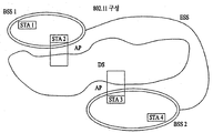
- FIG. 1 is a diagram illustrating an example of a configuration of a WLAN system.
- the WLAN system includes one or more basic service sets (BSSs).
- BSS is a set of stations (STAs) that can successfully synchronize and communicate with each other.
- An STA is a logical entity that includes a medium access control (MAC) and a physical layer interface to a wireless medium.
- the STA is an access point (AP) and a non-AP STA (Non-AP Station). Include.
- the portable terminal operated by the user among the STAs is a non-AP STA, and when referred to simply as an STA, it may also refer to a non-AP STA.
- a non-AP STA may be a terminal, a wireless transmit / receive unit (WTRU), a user equipment (UE), a mobile station (MS), a mobile terminal, or a mobile subscriber. It may also be called another name such as a mobile subscriber unit.
- the AP is an entity that provides an associated station (STA) coupled to the AP to access a distribution system (DS) through a wireless medium.
- STA station
- DS distribution system
- the AP may be called a centralized controller, a base station (BS), a Node-B, a base transceiver system (BTS), a personal basic service set central point / access point (PCP / AP), or a site controller.
- BSS can be divided into infrastructure BSS and Independent BSS (IBSS).
- IBSS Independent BSS
- the BBS shown in FIG. 1 is an IBSS.
- the IBSS means a BSS that does not include an AP. Since the IBSS does not include an AP, access to the DS is not allowed, thereby forming a self-contained network.
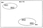
- FIG. 2 is a diagram illustrating another example of a configuration of a WLAN system.
- the BSS shown in FIG. 2 is an infrastructure BSS.
- Infrastructure BSS includes one or more STAs and APs.
- communication between non-AP STAs is performed via an AP.
- AP access point
- a plurality of infrastructure BSSs may be interconnected through a DS.
- a plurality of BSSs connected through a DS is called an extended service set (ESS).
- STAs included in the ESS may communicate with each other, and a non-AP STA may move from one BSS to another BSS while communicating seamlessly within the same ESS.
- the DS is a mechanism for connecting a plurality of APs.
- the DS is not necessarily a network, and there is no limitation on the form if it can provide a predetermined distribution service.
- the DS may be a wireless network such as a mesh network or a physical structure that connects APs to each other.
- FIG. 3 is a diagram for describing a channel in a 60 GHz band for explaining a channel bonding operation according to an embodiment of the present invention.
- channel 2 of the channels shown in FIG. 3 may be used in all regions and may be used as a default channel.
- Channels 2 and 3 can be used in most of the designations except Australia, which can be used for channel bonding.
- a channel used for channel bonding may vary, and the present invention is not limited to a specific channel.
- FIG. 4 is a diagram illustrating a basic method of performing channel bonding in a WLAN system.
- FIG. 4 illustrates the operation of 40 MHz channel bonding by combining two 20 MHz channels in an IEEE 802.11n system.
- 40/80/160 MHz channel bonding will be possible.
- the two exemplary channels of FIG. 4 include a primary channel and a secondary channel, so that the STA may examine the channel state in a CSMA / CA manner for the primary channel of the two channels. If the secondary channel is idle for a predetermined time (e.g. PIFS) at the time when the primary channel idles for a constant backoff interval and the backoff count becomes zero, the STA is assigned to the primary channel and Auxiliary channels can be combined to transmit data.
- PIFS a predetermined time
- channel bonding when channel bonding is performed based on contention as illustrated in FIG. 4, channel bonding may be performed only when the auxiliary channel is idle for a predetermined time at the time when the backoff count for the primary channel expires. Therefore, the use of channel bonding is very limited, and it is difficult to flexibly respond to the media situation.
- an aspect of the present invention proposes a method in which an AP transmits scheduling information to STAs to perform access on a scheduling basis. Meanwhile, another aspect of the present invention proposes a method of performing channel access based on the above-described scheduling or on a contention-based basis independently of the above-described scheduling. In addition, another aspect of the present invention proposes a method for performing communication through a spatial sharing technique based on beamforming.
- 5 is a view for explaining the configuration of the beacon interval.
- the time of the medium may be divided into beacon intervals. Lower periods within the beacon interval may be referred to as an access period. Different connection intervals within one beacon interval may have different access rules.
- the information about the access interval may be transmitted to the non-AP STA or the non-PCP by an AP or a personal basic service set control point (PCP).
- PCP personal basic service set control point
- one beacon interval may include one beacon header interval (BHI) and one data transfer interval (DTI).
- BHI may include a Beacon Transmission Interval (BTI), an Association Beamforming Training (A-BFT), and an Announcement Transmission Interval (ATI).
- BTI Beacon Transmission Interval
- A-BFT Association Beamforming Training
- ATI Announcement Transmission Interval
- the BTI means a section in which one or more DMG beacon frames can be transmitted.
- A-BFT refers to a section in which beamforming training is performed by an STA that transmits a DMG beacon frame during a preceding BTI.
- ATI means a request-response based management access interval between PCP / AP and non-PCP / non-AP STA.
- one or more Content Based Access Period (CBAP) and one or more Service Periods (SPs) may be allocated as data transfer intervals (DTIs).
- CBAP Content Based Access Period
- SPs Service Periods
- DTIs data transfer intervals
- PHY MCS Note Control PHY 0 Single carrier PHY (SC PHY) 1, ..., 1225, ..., 31 (low power SC PHY) OFDM PHY 13, ..., 24
- modulation modes can be used to meet different requirements (eg, high throughput or stability). Depending on your system, only some of these modes may be supported.
- FIG. 6 is a diagram for explaining a physical configuration of an existing radio frame.
- DMG Directional Multi-Gigabit
- the preamble of the radio frame may include a Short Training Field (STF) and a Channel Estimation (CE).
- the radio frame may include a header and a data field as a payload and optionally a training field for beamforming.
- FIG. 7 and 8 are views for explaining the configuration of the header field of the radio frame of FIG.
- FIG. 7 illustrates a case in which a single carrier (SC) mode is used.
- SC single carrier
- a header indicates information indicating an initial value of scrambling, a modulation and coding scheme (MCS), information indicating a length of data, and additional information.
- MCS modulation and coding scheme
- Information indicating the presence of a physical protocol data unit (PPDU), packet type, training length, aggregation, beam-framing request, last RSSI (Received Signal Strength Indicator), truncation, header check sequence (HCS) Information may be included.
- PPDU physical protocol data unit
- packet type packet type
- training length aggregation
- beam-framing request aggregation
- last RSSI Receiveived Signal Strength Indicator
- HCS header check sequence
- the header has 4 bits of reserved bits, which may be used in the following description.
- the OFDM header includes information indicating the initial value of scrambling, MCS, information indicating the length of data, information indicating the presence or absence of additional PPDUs, packet type, training length, aggregation, beam beaming request, last RSSI, truncation, Information such as a header check sequence (HCS) may be included.
- HCS header check sequence
- the header has 2 bits of reserved bits, and in the following description, such reserved bits may be utilized as in the case of FIG. 7.
- the IEEE 802.11ay system is considering introducing channel bonding and MIMO technology for the first time in the existing 11ad system.
- a new PPDU structure is needed. That is, the existing 11ad PPDU structure has limitations in supporting legacy terminals and implementing channel bonding and MIMO.
- a new field for the 11ay terminal may be defined after the legacy preamble and the legacy header field for supporting the legacy terminal.
- channel bonding and MIMO may be supported through the newly defined field.
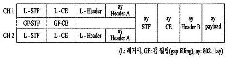
- FIG. 9 illustrates a PPDU structure according to one preferred embodiment of the present invention.
- the horizontal axis may correspond to the time domain and the vertical axis may correspond to the frequency domain.
- a frequency band (eg, 400 MHz band) of a predetermined size may exist between frequency bands (eg, 1.83 GHz) used in each channel.
- legacy preambles legacy STFs, legacy: CEs
- a new STF and a legacy ST can be simultaneously transmitted through a 400 MHz band between each channel. Gap filling of the CE field may be considered.
- the PPDU structure according to the present invention transmits ay STF, ay CE, ay header B, and payload in a broadband manner after legacy preamble, legacy header, and ay header A.
- ay header, ay Payload field, and the like transmitted after the header field may be transmitted through channels used for bonding.
- the ay header may be referred to as an enhanced directional multi-gigabit (EDMG) header to distinguish the ay header from the legacy header, and the name may be used interchangeably.
- EDMG enhanced directional multi-gigabit
- a total of six or eight channels may exist in 11ay, and a single STA may bond and transmit up to four channels.
- the ay header and ay Payload may be transmitted through 2.16 GHz, 4.32 GHz, 6.48 GHz, 8.64 GHz bandwidth.
- the PPDU format when repeatedly transmitting the legacy preamble without performing the gap-filling as described above may also be considered.
- ay STF, ay CE, and ay header B are replaced by a legacy preamble, legacy header, and ay header A without a GF-Filling and thus without the GF-STF and GF-CE fields shown by dotted lines in FIG. 8. It has a form of transmission.
- Beamforming is a mechanism for performing a link budget that a pair of STAs require for continuous communication.
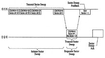
- BF training refers to a bi-directional sequence of BF frames using sector sweeps and provides the signaling necessary for each STA to determine the appropriate antenna system settings for transmission and reception. If the BF training is successfully completed, it can be said that the BF has been established.
- the BF frame includes all of a sector sweep (SSW) frame, an (EDMB) beacon frame, an SSW-Feedback frame, an SSW-ACK frame, or a BRP (Beam Refinement Protocol) frame. 10 shows an example of a beamforming training process applicable to the present invention.
- an STA that initiates BF training through transmission of a BF frame is called an initiator, and an STA that receives the BF frame and participates in the BF training initiated by the initiator is a responder ( responder).
- BF training that occurs within an Association BeamForming Training (A-BFT) assignment
- A-BFT Association BeamForming Training
- the AP or PCP / AP is an initiator, and the non-AP and non-PCP / AP STAs are responders.
- the idea within the SP assignment is in BF training, where the source (EDMG) STA of the SP is the initiator and the destination STA of the SP becomes the responder.
- TXOP Transmission Opportunity
- the TXOP holder is the initiator and the TXOP responder becomes the responder.
- the link from the initiator to the responder is called an initiator link and the link from the responder to the initiator is called a responder link.
- BF training begins with SLS (Sector Level Sweep) from the initiator. If requested by the initiator or responder, the SLS may be followed by the BRP (Beam Refinement Protocol).
- SLS System Level Sweep
- BRP Beam Refinement Protocol
- the purpose of the SLS phase is to enable communication between two STAs at the control PHY rate or higher MCS.
- the SLS phase only provides for transmitting BF training.
- the purpose of the BRP phase is to enable receive training and to enable iterative refinement of the antenna weight vector (AWV) of all transmitters and receivers at all STAs. If one of the STAs participating in the beam training chooses to use only one transmit antenna pattern, the reception training may be performed as part of the SLS step.
- ADV antenna weight vector
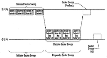
- the SLS step may include four elements: an initiator sweep (ISS) for training an initiator link and a responder sector sweep (RSS) for training a responder link. , SSW feedback, SSW ACK.
- ISS initiator sweep
- RSS responder sector sweep
- the initiator begins the SLS phase by sending the frame (s) of the ISS.
- the Responder does not begin sending the frame (s) of RSS before the ISS completes successfully. However, there may be an exception if the ISS occurs within the BTI.
- the initiator does not start SSW feedback before the RSS phase completes successfully. However, there may be an exception when the RSS is generated within the A-BFT.
- the Responder does not initiate the SSW ACK of the Initiator within the A-BFT.
- the Responder starts the SSW ACK of the initiator immediately after successful completion of the SSW feedback of the initiator.
- the BF frame transmitted by the initiator during the SLS phase may include an (EDMG) beacon frame, an SSW frame, and an SSW feedback frame.
- the BF frame transmitted by the responder may include an SSW frame and an SSW-ACK frame.
- TXSS Transmit Sector Sweep
- the initiator and responder poses their own sector of transport at the end of the SLS phase. If the ISS or RSS uses a receive sector sweep, each responder or initiator has its own receive sector.
- the STA does not change the transmit power during sector sweep.
- 11 and 12 show examples of an SLS step.
- the branch office has many sectors, and the responder has one transmitting sector and one receiving sector used in RSS.
- the responder transmits all responder SSW frames on the same transmission sector, while the initiator switches the receive antenna.
- the initiator has many transmission sectors and the responder has one transmission sector.
- receive training for the initiator may be performed at the BRP stage.
- SLS is a protocol for performing link detection in an 802.11ad system.
- a network node continuously transmits and receives a frame including the same information while changing only the direction of a beam.
- Indicators that indicate performance eg, Signal to Ratio (SNR), Received Signal Strength Indicator (RSSI), etc.
- SNR Signal to Ratio
- RSSI Received Signal Strength Indicator
- BRP can be summarized as follows.
- BRP is a protocol for fine-tuning the beam direction that can maximize the data rate in the beam direction determined by SLS or other means.
- the BRP includes beam training information defined for the BRP protocol and information reporting the training results. Beam training is performed using the frame. For example, the BRP transmits and receives a BRP frame using a beam determined by previous beam training, and performs beam training substantially using a beam training sequence included at the end of the successfully transmitted and received BRP frame. Beam training method.
- SLS uses the frame itself for beam training, but BRP may differ in that it uses only the beam training sequence.
- BT Beam Tracking
- Beam Tracking may be applied as an additional BF training method.
- BT Beam Tracking
- PHY header of the data frame by including a sequence for beam training at the end of the data frame, A beam training method of transmitting data and performing beam training at the same time.
- an STA may transmit and receive a signal using one or more channels.
- the STA decodes only one channel (for example, a primary channel), so that the STA receiving the signal not only receives the primary channel but also the secondary channel in order to properly receive the corresponding signal.
- Information may be needed that signals are transmitted using a secondary channel. More specifically, in order for the STA that receives the signal to properly receive the signal, channel configuration information on how many channels are available using the available channels may be needed.
- the present invention proposes a method for transmitting the channel configuration information using the Header-A field by optimizing the 11ay system.
- the present invention also proposes a method of transmitting channel configuration information of a PPDU to be transmitted later using a MAC frame (grant frame, trigger frame, or scheduling frame).
- the 11ay system to which the present invention is applicable may support up to eight channels, and support up to four channel bonding to transmit a signal to one STA.
- up to four channels may be bonded in the system for convenience of description, and an overlap case is excluded during channel bonding.
- a certain channel may be included in only one channel bonding and not included in a plurality of channel bonding (eg, two) when bonding a predetermined number (eg, two) channels.
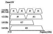
- a form of a channel that can be used for channel bonding or single channel transmission on a system supporting up to four channels may be represented as shown in FIG. 13.
- 13 is a diagram showing examples of channel bonding applicable to the present invention.
- the STA may transmit a signal using one channel type among # 1, # 2, # 3, and # 4. That is, the total number of cases of channel types that the STA can use for single channel transmission is four in total.
- the STA may transmit signals using the channel shape defined by # 9 by bonding # 1 and # 2 or by using the channel shape defined by # 11 by bonding # 3 and # 4. That is, the number of channel types that the STA can use for two channel bonding is two in total. In this case, as described above, the case of overlapping channels is excluded, and the case where the STA transmits signals by bonding # 2 and # 3 is excluded. In addition, since the available channel width varies according to each country and region, the form of the two-channel bonding described above may vary.
- the STA may transmit by using one of # 2, # 3, or # 4 when transmitting a single channel, and bonding # 2 and # 3 when bonding two channels.
- a signal may be transmitted or a signal may be transmitted by bonding # 3 and # 4, but in this case, since an overlay case is not allowed, only one of the above two cases may be applied.
- the STA may transmit signals using the channel type defined by # 17 by bonding # 1, # 2, and # 3, and when transmitting four channel bonding, the STA may # 1, # 2, # 3 and # 4 may be bonded to transmit a signal using a channel shape defined as # 25. Also in this case, channels different from the previous example may be bonded and mapped to different indices based on the available channel widths according to each country and region.
- channels different from the previous example may be bonded and mapped to different indices based on the available channel widths according to each country and region.
- it when using channel aggregation using two RF (Radio Frequency) chains, it can be expressed in the form of 2.16 GHz + 2.16 GHz, and the number of such forms is 4 C 2, which is 6 Has the number of cases.
- the number of channel bondings that the STA can use for signal transmission is 14 in total.
- an STA receiving a signal in a single channel transmission, although a corresponding channel operates as a primary channel, when two or more channels are bonded and operated, an STA receiving a signal must obtain information about which channel among the bonded channels is the primary channel. . This is because the terminal receiving the signal during the initial access performs the feedback on the I-TXSS during the SLS by transmitting the SSW frame through the primary channel. That is, if the STA receiving the signal does not acquire the information on the primary channel, the STA cannot know which channel to transmit the SSW frame, and thus the STA cannot perform the initial access.
- the present invention proposes the following two methods as a method for the STA to obtain information on the primary channel.
- the PCP / AP or STA transmits a signal only on the primary channel in the BTI period.
- the PCP / AP or STA has the capability of channel bonding, when the PCP / AP or STA transmits a beacon frame or a signal in the BTI section, the PCP / AP or STA transmits the corresponding signal only using the primary channel. That is, the same signal is not duplicated and transmitted on multiple channels. Through this, the STA receiving the beacon frame may recognize that the channel on which the signal is transmitted is the main channel.
- the PCP / AP or STA indicates the bonding channel information and the information on the primary channel together.
- the STA that receives the beacon frame may not know which channel is the primary channel. Accordingly, when the PCP / AP or the STA transmits information on the bonding channel to the STA that receives the corresponding signal, the PCP / AP or the STA may indicate information on which channel among the bonding channels is the primary channel.
- the STA when operating as described above (2), the STA may have a total of 27 channel combinations as follows.
- the PCP / AP or STA needs a field having a size of at least 5 bits to indicate the channel combination as described above.
- the corresponding information may be transmitted through the EDMG Header-A or the EDMG Header-B.
- the STA receiving the signal decodes one channel and then decodes the EDMG Header-A or EDMG Header-B field to obtain the channel combination information.
- the STA may change the reception procedure by recognizing channel bonding or channel combining. have.
- the STA that receives the signal includes a preamble, a legacy part, and an EDMG Header-A and EDMG.
- the Header-B field may also be received by changing the reception procedure by channel bonding or channel combining.
- the present invention proposes a method for reducing the number of bits required to indicate such a channel combination.
- channel combination information is transmitted using EDMG Header-A or EDMG Header-B.
- an STA that receives a signal operates as a reception procedure for decoding only one channel and receives the corresponding signal.
- the configuration may be extended even when the above channel combination information is transmitted through a MAC frame.
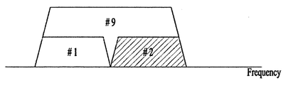
- a STA receiving a signal may distinguish whether the two-channel bonded channel type is channel # 9 or channel # 11 based on whether the detection or decoding is successful.
- only adjacent channels are bonded, and thus only need to indicate whether a channel having a lower frequency than the detected channel is bonded or an adjacent channel having a higher frequency than the detected channel is bonded. Therefore, in the case of two-channel bonding, the number of cases of information to be indicated is reduced to two.
- the PCP / AP or STA may transmit a signal by bonding channel # 1 and channel # 2.
- channel # 2 may be a primary channel.
- the STA receiving the signal decodes the EDMG Header-A or the EDMG Header-B in any one of channel # 1 or channel # 2 without obtaining information on channel bonding, By success of the decoding, it can be recognized that the two-channel bonding and two-channel bonding defined by # 9 at the same time.
- the STA acquires all of the channel configuration information by obtaining information on whether a low channel is a main channel or an upper channel having a high frequency among the channels constituting # 9. Can be obtained.
- the PCP / AP or STA may perform aggregation on adjacent channels as well as non-adjacent channels.
- the channel configuration of channel combination is the combination of # 1 and # 3 (two channel combinations are possible depending on the position of the main channel) and the combination of # 2 and # 4 (2 depending on the position of the main channel) Branch channel combination is possible) and # 1 and # 4 are combined (two channels can be combined depending on the position of the main channel) and # 2 and # 3 are combined (2 depending on the position of the main channel) Branch channel combinations are possible).
- the STA receiving the signal decodes the EDMG Header-A or EDMG Header-B received through any channel. Subsequently, the STA may recognize channel combining transmission through the decoding, and simultaneously extract some of the channel combining combinations in which the corresponding channel is used as a subset by using the position of the decoded channel. Subsequently, the configuration information on the main channel may indicate whether a channel having a lower frequency than the channel detected as the two channel bonding is the main channel or a channel having a high frequency is the main channel.
- the channel combinations through which the PCP / AP or STA can transmit signals may be represented by the following cases.
- the PCP / AP or STA may transmit a signal using one of a total of 16 channel configuration combinations, and the number of bits indicating the channel configuration combination may be represented by a total of 4 bits. have.
- case of 6 and 8 may be combined into one
- case of 7 and 9 may be combined into one and may indicate one of a total of 14 channel configuration combinations.
- the information on the channel configuration combination may be transmitted using a MAC frame.
- FIG. 15 is a diagram illustrating an example of an operation element and an operation information field of a MAC frame applicable to the present invention.
- the PCP / AP or STA When the PCP / AP or STA transmits the above-described channel configuration combination using a MAC frame, the PCP / AP or STA supports the legacy terminals by using the reserved bits of the operation element as shown in FIG. 15.
- Channel configuration information may be transmitted. A configuration of an operation element is shown in FIG. 15, and channel configuration information may be indicated using a 13-bit reserved bit in the operation element as shown in FIG. 15.
- the DMB operation element defined in the 11ad system may be utilized, or a new EDMG operation element for the 11ay system may be defined.
- the PCP / AP or STA may transmit channel configuration information through a capability element in a MAC frame.
- the DMB capability element defined in the 11ad system may be utilized, or a new EDMG capability element for the 11ay system may be defined.
- An STA that transmits a signal (hereinafter, referred to as a first STA) is an operating channel configured to operate like a primary channel or a primary channel set through a system to an STA that receives a signal (hereinafter, referred to as a second STA).
- a beacon frame is transmitted through an operation channel, or information indicating the primary channel is transmitted. More specifically, the first STA may transmit the beacon frame only to the primary channel among a plurality of channels in order to inform the second STA which channel is the primary channel. In this way, the second STA may recognize that the channel on which the beacon frame is received is the primary channel, or may recognize which channel is the primary channel by decoding the received information. In this case, the beacon frame may be transmitted during the BTI period.
- the first STA transmits information indicating a plurality of channels including the primary channel through which a signal is transmitted to the second STA, and transmits a signal to the second STA through the plurality of channels.
- the plurality of channels may include up to four channels of eight channels.
- the plurality of channels may be adjacent to each other as shown in FIG. 18.
- the present invention considers a case where a signal is transmitted by applying channel aggregation as well as channel bonding.
- the two channels may include two channels adjacent to each other or two channels not adjacent to each other.
- the first STA transmits information indicating the primary channel
- information indicating the primary channel information indicating the primary channel
- information indicating the primary channel information indicating a plurality of channels through which the signal is transmitted are EDMG Headers. It may be transmitted through the -A field or through the EDMG operation element field.
- the information indicating the primary channel, the information indicating the primary channel, and the information indicating the plurality of channels through which the signal is transmitted may include one indication field (eg, an EDMG Header-A or EDMG operation element field) described above. Can be indicated simultaneously.
- one indication field eg, an EDMG Header-A or EDMG operation element field
- a second STA may identify the information indicating the primary channel and the primary channel.
- the indicating information and the information indicating the plurality of channels through which the signal is transmitted are received using one of the plurality of channels, and the second STA transmits the signal transmitted from the first STA to the plurality of channels. Can be received using all of them.
- the beacon frame may be transmitted during a BTI (Beacon Transmission Interval).
- BTI Beacon Transmission Interval
- the beacon frame may not be transmitted in any channel other than the main channel.
- 16 is a view for explaining an apparatus for implementing the method as described above.
- the wireless device 100 transmits a signal by bonding or combining a plurality of channels in the above description
- the wireless device 150 transmits a signal transmitted by bonding or combining a plurality of channels in the above description.
- each station may correspond to an 11ay terminal or a PCP / AP.
- a station transmitting a signal is called a transmitting device 100
- a station receiving a signal is called a receiving device 150.
- the transmitter 100 may include a processor 110, a memory 120, and a transceiver 130
- the receiver device 150 may include a processor 160, a memory 170, and a transceiver 180. can do.
- the transceivers 130 and 180 may transmit / receive radio signals and may be executed in a physical layer such as IEEE 802.11 / 3GPP.
- the processors 110 and 160 are executed in the physical layer and / or the MAC layer and are connected to the transceivers 130 and 180.
- the processors 110 and 160 may perform the aforementioned UL MU scheduling procedure.
- the processors 110 and 160 and / or the transceivers 130 and 180 may include application-specific integrated circuits (ASICs), other chipsets, logic circuits, and / or data processors.
- the memory 120, 170 may include read-only memory (ROM), random access memory (RAM), flash memory, memory card, storage medium and / or other storage unit.
- ROM read-only memory
- RAM random access memory
- flash memory memory card
- storage medium storage medium and / or other storage unit.
- the method described above can be executed as a module (eg, process, function) that performs the functions described above.
- the module may be stored in the memories 120 and 170 and may be executed by the processors 110 and 160.
- the memories 120 and 170 may be disposed inside or outside the processes 110 and 160, and may be connected to the processes 110 and 160 by well-known means.
- the present invention has been described assuming that it is applied to an IEEE 802.11-based WLAN system, but the present invention is not limited thereto.
- the present invention can be applied in the same manner to various wireless systems capable of data transmission based on channel bonding.
Abstract
The present specification relates to a method for transmitting and receiving signals by a station in a wireless LAN (WLAN) system. More specifically, the present specification proposes a method for providing information on a primary channel and information on a channel for transmitting signals when a station transmits signals by bonding or combining a plurality of channels, and suggests a method for transmitting and receiving signals on the basis of such method for providing information, and an apparatus therefor.
Description
이하의 설명은 무선랜(WLAN) 시스템에서의 스테이션의 동작 방법에 대한 것으로서, 보다 구체적으로 무선랜 시스템에서 스테이션이 복수의 채널을 본딩 또는 결합하여 신호를 전송하는 경우, 신호를 전송하는 채널 정보 및 상기 채널 중 주 채널(primary channel)에 대한 정보를 제공하는 방법을 제안하고, 이에 기반하여 스테이션이 신호를 송수신하는 방법 및 이를 위한 장치에 대한 것이다.The following description relates to a method of operating a station in a WLAN system. More specifically, when a station transmits signals by bonding or combining a plurality of channels in a WLAN system, channel information for transmitting a signal and The present invention proposes a method for providing information on a primary channel among the channels, and a method for transmitting and receiving a signal based on the station and an apparatus therefor.
무선랜 기술에 대한 표준은 IEEE(Institute of Electrical and Electronics Engineers) 802.11 표준으로서 개발되고 있다. IEEE 802.11a 및 b는 2.4. GHz 또는 5 GHz에서 비면허 대역(unlicensed band)을 이용하고, IEEE 802.11b는 11 Mbps의 전송 속도를 제공하고, IEEE 802.11a는 54 Mbps의 전송 속도를 제공한다. IEEE 802.11g는 2.4 GHz에서 직교 주파수 분할 다중화(Orthogonal frequency-division multiplexing, OFDM)를 적용하여, 54 Mbps의 전송 속도를 제공한다. IEEE 802.11n은 다중입출력 OFDM(multiple input multiple output-OFDM, MIMO-OFDM)을 적용하여, 4 개의 공간적인 스트림(spatial stream)에 대해서 300 Mbps의 전송 속도를 제공한다. IEEE 802.11n에서는 채널 대역폭(channel bandwidth)을 40 MHz까지 지원하며, 이 경우에는 600 Mbps의 전송 속도를 제공한다. The standard for WLAN technology is being developed as an Institute of Electrical and Electronics Engineers (IEEE) 802.11 standard. IEEE 802.11a and b are described in 2.4. Using unlicensed band at GHz or 5 GHz, IEEE 802.11b provides a transmission rate of 11 Mbps and IEEE 802.11a provides a transmission rate of 54 Mbps. IEEE 802.11g applies orthogonal frequency-division multiplexing (OFDM) at 2.4 GHz to provide a transmission rate of 54 Mbps. IEEE 802.11n applies multiple input multiple output OFDM (MIMO-OFDM) to provide a transmission rate of 300 Mbps for four spatial streams. IEEE 802.11n supports channel bandwidths up to 40 MHz, in this case providing a transmission rate of 600 Mbps.
상술한 무선랜 표준은 최대 160MHz 대역폭을 사용하고, 8개의 공간 스트림을 지원하여 최대 1Gbit/s의 속도를 지원하는 IEEE 802.11ac 표준을 거쳐, IEEE 802.11ax 표준화에 대한 논의가 이루어지고 있다.The WLAN standard uses a maximum of 160MHz bandwidth, supports eight spatial streams, and supports IEEE 802.11ax standard through an IEEE 802.11ac standard supporting a speed of up to 1Gbit / s.
한편, IEEE 802.11ad에서는 60 GHz 대역에서의 초고속 처리율을 위한 성능향상을 규정하고 있으며, 이러한 IEEE 802.11ad 시스템에 처음으로 채널 본딩 및 MIMO 기술을 도입하기 위한 IEEE 802.11ay에 대한 논의가 이루어지고 있다.Meanwhile, IEEE 802.11ad defines performance enhancement for ultra-high throughput in the 60 GHz band, and IEEE 802.11ay for channel bonding and MIMO technology is introduced for the first time in the IEEE 802.11ad system.
본 발명이 적용 가능한 11ay 시스템에서는 채널 본딩 또는 채널 결합되어 하나 이상의 채널을 이용하여 신호가 전송될 수 있다.In the 11ay system to which the present invention is applicable, a signal may be transmitted using one or more channels by channel bonding or channel combining.
이에, 본 발명에서는 신호를 전송하는 11ay 단말 (예: PCP/AP 또는 스테이션)이 가용 채널 중 몇 개의 채널을 이용하여 신호를 전송하는지에 대한 채널 구성 정보를 수신 11ay 단말에게 제공하고, 이에 기반하여 신호를 송수신하는 방법을 제안한다.Accordingly, in the present invention, the 11ay terminal (eg, PCP / AP or station) that transmits a signal provides channel configuration information on how many channels are available to the receiving 11ay terminal and based on this. We propose a method for transmitting and receiving signals.
상술한 바와 같은 과제를 해결하기 위한 본 발명의 일 측면에서는 무선랜(WLAN) 시스템에서 제1 스테이션(STA)이 제2 STA에게 신호를 전송하는 방법에 있어서, 주 채널(primary channel)을 통해 비콘 프레임을 전송하거나 상기 주 채널을 지시하는 정보를 상기 제2 STA에게 전송;신호가 전송되는 상기 주 채널을 포함하는 복수의 채널들을 지시하는 정보를 상기 제2 STA에게 전송; 및 상기 복수의 채널들을 통해 상기 제2 STA에게 신호를 전송;하는 것을 포함하는, 무선랜 시스템에서의 신호 전송 방법을 제안한다.According to an aspect of the present invention for solving the above problems, in a method of transmitting a signal to a second STA by a first station (STA) in a WLAN system, a beacon through a primary channel (primary channel) Transmitting a frame or information indicating the primary channel to the second STA; transmitting information indicating a plurality of channels including the primary channel through which a signal is transmitted to the second STA; And transmitting a signal to the second STA through the plurality of channels.
한편, 본 발명의 다른 측면에서는 무선랜(WLAN) 시스템에서 신호를 전송하는 제1 스테이션 장치에 있어서, 상기 제1 스테이션 장치는 하나 이상의 RF(Radio Frequency) 체인을 가지고, 제2 STA과 신호를 송수신하도록 구성되는 송수신부; 및 상기 송수신부와 연결되어, 상기 제2 STA와 신호를 송수신한 신호를 처리하는 프로세서를 포함하되, 상기 프로세서는, 주 채널(primary channel)을 통해 비콘 프레임을 전송하거나 상기 주 채널을 지시하는 정보를 상기 제2 STA에게 전송; 신호가 전송되는 상기 주 채널을 포함하는 복수의 채널들을 지시하는 정보를 상기 제2 STA에게 전송; 및 상기 하나 이상의 채널을 통해 상기 제2 STA에게 신호를 전송;하도록 구성되는, 스테이션 장치를 제안한다.Meanwhile, in another aspect of the present invention, in a first station apparatus for transmitting a signal in a WLAN system, the first station apparatus has one or more RF (Radio Frequency) chains, and transmits and receives a signal with a second STA. A transceiver configured to be configured to be; And a processor connected to the transceiver, the processor processing a signal transmitted / received with the second STA, wherein the processor transmits a beacon frame through a primary channel or indicates information on the primary channel. Send to the second STA; Transmitting information indicating a plurality of channels including the primary channel through which a signal is transmitted to the second STA; And transmit a signal to the second STA via the one or more channels.
한편, 본 발명의 또 다른 측면에서는 무선랜(WLAN) 시스템에서 제1 스테이션(STA)이 제2 STA으로부터 신호를 수신하는 방법에 있어서, 상기 제2 STA으로부터 주 채널(primary channel)을 통해 비콘 프레임을 수신하거나 상기 주 채널을 지시하는 정보를 수신함으로써 상기 주 채널에 대한 정보를 획득; 신호가 전송되는 상기 주 채널을 포함하는 복수의 채널들을 지시하는 정보를 상기 제2 STA으로부터 수신; 및 상기 복수의 채널들을 통해 상기 제2 STA으로부터 신호를 수신;하는 것을 포함하는, 무선랜 시스템에서의 신호 수신 방법을 제안한다.Meanwhile, in another aspect of the present invention, in a method in which a first station (STA) receives a signal from a second STA in a WLAN system, a beacon frame through a primary channel from the second STA Obtaining information about the primary channel by receiving a signal or receiving information indicating the primary channel; Receiving from the second STA information indicating a plurality of channels including the primary channel through which a signal is transmitted; And receiving a signal from the second STA through the plurality of channels.
한편, 본 발명의 또 다른 측면에서는 무선랜(WLAN) 시스템에서 신호를 수신하는 제1 스테이션 장치에 있어서, 상기 제1 스테이션은 하나 이상의 RF(Radio Frequency) 체인을 가지고, 제2 STA과 신호를 송수신하도록 구성되는 송수신부; 및 상기 송수신부와 연결되어, 상기 제2 STA과 송수신한 신호를 처리하는 프로세서를 포함하되, 상기 프로세서는, 상기 제2 STA으로부터 주 채널(primary channel)을 통해 비콘 프레임을 수신하거나 상기 주 채널을 지시하는 정보를 수신함으로써 상기 주 채널에 대한 정보를 획득; 신호가 전송되는 상기 주 채널을 포함하는 복수의 채널들을 지시하는 정보를 상기 제2 STA으로부터 수신; 및 상기 복수의 채널들을 통해 상기 제2 STA에게 신호를 수신;하도록 구성되는, 스테이션 장치를 제안한다.In another aspect of the present invention, in a first station apparatus for receiving a signal in a WLAN system, the first station has one or more RF (Radio Frequency) chains, and transmits and receives a signal with a second STA. A transceiver configured to be configured to be; And a processor connected to the transceiver, the processor processing a signal transmitted and received with the second STA, wherein the processor receives a beacon frame through a primary channel from the second STA or receives the primary channel. Obtaining information about the primary channel by receiving indicating information; Receiving from the second STA information indicating a plurality of channels including the primary channel through which a signal is transmitted; And receive a signal to the second STA via the plurality of channels.
여기서, 상기 복수의 채널들은 2개 내지 4개 채널을 포함할 수 있다.Here, the plurality of channels may include 2 to 4 channels.
이때, 상기 복수 개의 채널들은 서로 인접한 채널들일 수 있다.In this case, the plurality of channels may be adjacent to each other.
특히 상기 복수의 채널들이 2개 채널들인 경우, 상기 2 개 채널들은 서로 인접한 2개 채널 또는 서로 인접하지 않은 2개 채널을 포함할 수 있다.In particular, when the plurality of channels are two channels, the two channels may include two channels adjacent to each other or two channels not adjacent to each other.
이때, 상기 주 채널을 지시하는 정보가 전송되는 경우, 상기 주 채널을 지시하는 정보 및 상기 신호가 전송되는 복수의 채널들을 지시하는 정보는 EDMG (enhanced directional multi-gigabit) 헤더 A 필드를 통해 전송될 수 있다.In this case, when information indicating the primary channel is transmitted, information indicating the primary channel and information indicating a plurality of channels through which the signal is transmitted may be transmitted through an enhanced directional multi-gigabit (EDMG) header A field. Can be.
또한, 상기 주 채널을 지시하는 정보가 전송되는 경우, 상기 주 채널을 지시하는 정보 및 상기 신호가 전송되는 복수의 채널들을 지시하는 정보는 EDMG (enhanced directional multi-gigabit) 동작 요소 (operation element)를 통해 전송될 수 있다.In addition, when information indicating the primary channel is transmitted, the information indicating the primary channel and the information indicating a plurality of channels through which the signal is transmitted include an enhanced directional multi-gigabit (EDMG) operation element. Can be sent through.
또한, 상기 주 채널을 지시하는 정보가 전송되는 경우, 상기 주 채널을 지시하는 정보 및 상기 신호가 전송되는 복수의 채널들을 지시하는 정보는 하나의 지시 필드를 통해 동시에 지시될 수 있다.In addition, when information indicating the primary channel is transmitted, information indicating the primary channel and information indicating a plurality of channels through which the signal is transmitted may be simultaneously indicated through one indication field.
또한, 상기 제1 STA이 상기 주 채널을 통해 비콘 프레임을 전송하는 경우, 상기 비콘 프레임은 BTI (Beacon Transmission Interval) 동안 전송될 수 있다.In addition, when the first STA transmits a beacon frame through the primary channel, the beacon frame may be transmitted during a BTI (Beacon Transmission Interval).
여기서, 바람직하게는 상기 비콘 프레임은 상기 주 채널을 제외한 다른 채널에서는 전송되지 않을 수 있다.Here, preferably, the beacon frame may not be transmitted in any channel other than the main channel.
상기와 같은 구성을 통해, 본 발명에 따른 스테이션은 하나 이상의 채널을 본딩 또는 결합하여 서로 간 신호를 오류 없이 송수신할 수 있다는 효과가 있다.Through the above configuration, the station according to the present invention has an effect that the signals can be transmitted and received to each other without error by bonding or combining one or more channels.
본 발명에서 얻을 수 있는 효과는 이상에서 언급한 효과들로 제한되지 않으며, 언급하지 않은 또 다른 효과들은 아래의 기재로부터 본 발명이 속하는 기술분야에서 통상의 지식을 가진 자에게 명확하게 이해될 수 있을 것이다.The effects obtainable in the present invention are not limited to the above-mentioned effects, and other effects not mentioned above may be clearly understood by those skilled in the art from the following description. will be.
본 명세서에 첨부되는 도면은 본 발명에 대한 이해를 제공하기 위한 것으로서 본 발명의 다양한 실시형태들을 나타내고 명세서의 기재와 함께 본 발명의 원리를 설명하기 위한 것이다. BRIEF DESCRIPTION OF THE DRAWINGS The drawings appended hereto are for the purpose of providing an understanding of the present invention and for illustrating various embodiments of the present invention and for describing the principles of the present invention together with the description of the specification.
도 1은 무선랜 시스템의 구성의 일례를 나타낸 도면이다.1 is a diagram illustrating an example of a configuration of a WLAN system.
도 2는 무선랜 시스템의 구성의 다른 예를 나타낸 도면이다.2 is a diagram illustrating another example of a configuration of a WLAN system.
도 3은 본 발명의 일 실시형태에 따른 채널 본딩 동작 설명을 위한 60GHz 대역에서의 채널을 설명하기 위한 도면이다.3 is a diagram for describing a channel in a 60 GHz band for explaining a channel bonding operation according to an embodiment of the present invention.
도 4는 무선랜 시스템에서 채널 본딩을 수행하는 기본적인 방법을 설명하기 위한 도면이다.4 is a diagram illustrating a basic method of performing channel bonding in a WLAN system.
도 5는 비콘 간격의 구성을 설명하기 위한 도면이다.5 is a view for explaining the configuration of the beacon interval.
도 6은 기존 무선 프레임의 물리 구성을 설명하기 위한 도면이다.6 is a diagram for explaining a physical configuration of an existing radio frame.
도 7 및 도 8은 도 6의 무선 프레임의 헤더 필드의 구성을 설명하기 위한 도면이다.7 and 8 are views for explaining the configuration of the header field of the radio frame of FIG.
도 9는 본 발명에 적용 가능한 PPDU 구조를 도시한 도면이다.9 illustrates a PPDU structure applicable to the present invention.
도 10은 본 발명에 적용 가능한 빔포밍 트레이닝 과정의 일 예를 나타낸다.10 shows an example of a beamforming training process applicable to the present invention.
도 11 및 도 12는 SLS 단계의 예시들을 나타낸 도면이다.11 and 12 show examples of an SLS step.
도 13은 본 발명에 적용 가능한 채널 본딩의 예시들을 나타낸 도면이다.13 is a diagram showing examples of channel bonding applicable to the present invention.
도 14는 2 채널 본딩의 일 예를 나타낸 것으로, 이중 channel #2가 주 채널인 일 예를 나타낸 도면이다.14 illustrates an example of two-channel bonding, in which dual channel # 2 is an example of a primary channel.
도 15는 본 발명에 적용 가능한 MAC 프레임의 동작 요소 (operation element) 및 동작 정보 필드 (operation information field)의 예시를 나타낸 도면이다.FIG. 15 is a diagram illustrating an example of an operation element and an operation information field of a MAC frame applicable to the present invention.
도 16은 상술한 바와 같은 방법을 구현하기 위한 장치를 설명하기 위한 도면이다.16 is a view for explaining an apparatus for implementing the method as described above.
이하, 본 발명에 따른 바람직한 실시 형태를 첨부된 도면을 참조하여 상세하게 설명한다. 첨부된 도면과 함께 이하에 개시될 상세한 설명은 본 발명의 예시적인 실시형태를 설명하고자 하는 것이며, 본 발명이 실시될 수 있는 유일한 실시형태를 나타내고자 하는 것이 아니다.Hereinafter, exemplary embodiments of the present invention will be described in detail with reference to the accompanying drawings. The detailed description, which will be given below with reference to the accompanying drawings, is intended to explain exemplary embodiments of the present invention and is not intended to represent the only embodiments in which the present invention may be practiced.
이하의 상세한 설명은 본 발명의 완전한 이해를 제공하기 위해서 구체적 세부사항을 포함한다. 그러나 당업자는 본 발명이 이러한 구체적 세부사항 없이도 실시될 수 있음을 안다. 몇몇 경우, 본 발명의 개념이 모호해지는 것을 피하기 위하여 공지의 구조 및 장치는 생략되거나, 각 구조 및 장치의 핵심기능을 중심으로 한 블록도 형식으로 도시된다. The following detailed description includes specific details in order to provide a thorough understanding of the present invention. However, one of ordinary skill in the art appreciates that the present invention may be practiced without these specific details. In some instances, well-known structures and devices are omitted or shown in block diagram form, centering on the core functions of each structure and device, in order to avoid obscuring the concepts of the present invention.
본 발명이 적용되는 이동통신 시스템은 다양하게 존재할 수 있으나, 이하에서는 이동통신 시스템의 일례로서 무선랜 시스템에 대해 구체적으로 설명한다.There may be various mobile communication systems to which the present invention is applied. Hereinafter, the WLAN system will be described in detail as an example of the mobile communication system.
1. One.
무선랜(Wireless LAN, Wireless LAN,
WLANWLAN
) 시스템) system
1-1. 무선랜 시스템 일반1-1. WLAN System General
도 1은 무선랜 시스템의 구성의 일례를 나타낸 도면이다.1 is a diagram illustrating an example of a configuration of a WLAN system.
도 1에 도시된 바와 같이, 무선랜 시스템은 하나 이상의 기본 서비스 세트(Basic Service Set, BSS)를 포함한다. BSS는 성공적으로 동기화를 이루어서 서로 통신할 수 있는 스테이션(Station, STA)의 집합이다. As shown in FIG. 1, the WLAN system includes one or more basic service sets (BSSs). A BSS is a set of stations (STAs) that can successfully synchronize and communicate with each other.
STA는 매체 접속 제어(Medium Access Control, MAC)와 무선 매체에 대한 물리계층(Physical Layer) 인터페이스를 포함하는 논리 개체로서, 액세스 포인트(access point, AP)와 비AP STA(Non-AP Station)을 포함한다. STA 중에서 사용자가 조작하는 휴대용 단말은 Non-AP STA로써, 단순히 STA라고 할 때는 Non-AP STA을 가리키기도 한다. Non-AP STA는 단말(terminal), 무선 송수신 유닛(Wireless Transmit/Receive Unit, WTRU), 사용자 장비(User Equipment, UE), 이동국(Mobile Station, MS), 휴대용 단말(Mobile Terminal), 또는 이동 가입자 유닛(Mobile Subscriber Unit) 등의 다른 명칭으로도 불릴 수 있다. An STA is a logical entity that includes a medium access control (MAC) and a physical layer interface to a wireless medium. The STA is an access point (AP) and a non-AP STA (Non-AP Station). Include. The portable terminal operated by the user among the STAs is a non-AP STA, and when referred to simply as an STA, it may also refer to a non-AP STA. A non-AP STA may be a terminal, a wireless transmit / receive unit (WTRU), a user equipment (UE), a mobile station (MS), a mobile terminal, or a mobile subscriber. It may also be called another name such as a mobile subscriber unit.
그리고, AP는 자신에게 결합된 STA(Associated Station)에게 무선 매체를 통해 분배 시스템(Distribution System, DS)으로의 접속을 제공하는 개체이다. AP는 집중 제어기, 기지국(Base Station, BS), Node-B, BTS(Base Transceiver System), PCP/AP(personal basic service set central point/access point) 또는 사이트 제어기 등으로 불릴 수도 있다. The AP is an entity that provides an associated station (STA) coupled to the AP to access a distribution system (DS) through a wireless medium. The AP may be called a centralized controller, a base station (BS), a Node-B, a base transceiver system (BTS), a personal basic service set central point / access point (PCP / AP), or a site controller.
BSS는 인프라스트럭처(infrastructure) BSS와 독립적인(Independent) BSS(IBSS)로 구분할 수 있다.BSS can be divided into infrastructure BSS and Independent BSS (IBSS).
도 1에 도시된 BBS는 IBSS이다. IBSS는 AP를 포함하지 않는 BSS를 의미하고, AP를 포함하지 않으므로, DS로의 접속이 허용되지 않아서 자기 완비적 네트워크(self-contained network)를 이룬다.The BBS shown in FIG. 1 is an IBSS. The IBSS means a BSS that does not include an AP. Since the IBSS does not include an AP, access to the DS is not allowed, thereby forming a self-contained network.
도 2는 무선랜 시스템의 구성의 다른 예를 나타낸 도면이다.2 is a diagram illustrating another example of a configuration of a WLAN system.
도 2에 도시된 BSS는 인프라스트럭처 BSS이다. 인프라스트럭처 BSS는 하나 이상의 STA 및 AP를 포함한다. 인프라스트럭처 BSS에서 비AP STA들 사이의 통신은 AP를 경유하여 이루어지는 것이 원칙이나, 비AP STA 간에 직접 링크(link)가 설정된 경우에는 비AP STA들 사이에서 직접 통신도 가능하다. The BSS shown in FIG. 2 is an infrastructure BSS. Infrastructure BSS includes one or more STAs and APs. In the infrastructure BSS, communication between non-AP STAs is performed via an AP. However, when a direct link is established between non-AP STAs, direct communication between non-AP STAs is also possible.
도 2에 도시된 바와 같이, 복수의 인프라스트럭처 BSS는 DS를 통해 상호 연결될 수 있다. DS를 통하여 연결된 복수의 BSS를 확장 서비스 세트(Extended Service Set, ESS)라 한다. ESS에 포함되는 STA들은 서로 통신할 수 있으며, 동일한 ESS 내에서 비AP STA는 끊김 없이 통신하면서 하나의 BSS에서 다른 BSS로 이동할 수 있다. As shown in FIG. 2, a plurality of infrastructure BSSs may be interconnected through a DS. A plurality of BSSs connected through a DS is called an extended service set (ESS). STAs included in the ESS may communicate with each other, and a non-AP STA may move from one BSS to another BSS while communicating seamlessly within the same ESS.
DS는 복수의 AP들을 연결하는 메커니즘(mechanism)으로서, 반드시 네트워크일 필요는 없으며, 소정의 분배 서비스를 제공할 수 있다면 그 형태에 대해서는 아무런 제한이 없다. 예컨대, DS는 메쉬(mesh) 네트워크와 같은 무선 네트워크일 수도 있고, AP들을 서로 연결시켜 주는 물리적인 구조물일 수도 있다. The DS is a mechanism for connecting a plurality of APs. The DS is not necessarily a network, and there is no limitation on the form if it can provide a predetermined distribution service. For example, the DS may be a wireless network such as a mesh network or a physical structure that connects APs to each other.
이상을 바탕으로 무선랜 시스템에서 채널 본딩 방식에 대해 설명한다.Based on the above, the channel bonding method in the WLAN system will be described.
1-2. 무선랜 시스템에서의 채널 1-2. Channel in WLAN system
본딩Bonding
도 3은 본 발명의 일 실시형태에 따른 채널 본딩 동작 설명을 위한 60GHz 대역에서의 채널을 설명하기 위한 도면이다.3 is a diagram for describing a channel in a 60 GHz band for explaining a channel bonding operation according to an embodiment of the present invention.
도 3에 도시된 바와 같이 60GHz 대역에서는 4개의 채널이 구성될 수 있으며, 일반 채널 대역폭은 2.16GHz일 수 있다. 60 GHz에서 사용 가능한 ISM 대역 (57 GHz ~ 66 GHz)은 각국 상황에 따라 다르게 규정될 수 있다. 일반적으로 도 3에 도시된 채널 중 채널 2는 모든 지역에서 사용 가능하여 default 채널로 사용될 수 있다. 호주를 제외한 대부분의 지적에서 채널 2 및 채널 3을 사용할 수 있으며, 이를 채널 본딩에 활용할 수 있다. 다만, 채널 본딩에 활용되는 채널은 다양할 수 있으며, 본 발명은 특정 채널에 한정되지 않는다.As shown in FIG. 3, four channels may be configured in the 60 GHz band, and a general channel bandwidth may be 2.16 GHz. The ISM bands available from 60 GHz (57 GHz to 66 GHz) may be defined differently in different countries. In general, channel 2 of the channels shown in FIG. 3 may be used in all regions and may be used as a default channel. Channels 2 and 3 can be used in most of the designations except Australia, which can be used for channel bonding. However, a channel used for channel bonding may vary, and the present invention is not limited to a specific channel.
도 4는 무선랜 시스템에서 채널 본딩을 수행하는 기본적인 방법을 설명하기 위한 도면이다.4 is a diagram illustrating a basic method of performing channel bonding in a WLAN system.
도 4의 예는 IEEE 802.11n 시스템에서 2개의 20MHz 채널을 결합하여 40 MHz 채널 본딩으로 동작하는 것을 예를 들어 설명한다. IEEE 802.11ac 시스템의 경우 40/80/160 MHz 채널 본딩이 가능할 것이다.The example of FIG. 4 illustrates the operation of 40 MHz channel bonding by combining two 20 MHz channels in an IEEE 802.11n system. For IEEE 802.11ac systems, 40/80/160 MHz channel bonding will be possible.
도 4의 예시적인 2개의 채널은 주 채널(Primary Channel) 및 보조 채널(Secondary Channel)을 포함하여, STA는 상기 2개의 채널 중 주 채널에 대해 CSMA/CA 방식으로 채널 상태를 검토할 수 있다. 만일 주 채널이 일정한 백오프 간격(backoff interval) 동안 유휴(idle)하여 백오프 카운트가 0이 되는 시점에서, 보조 채널이 소정 시간(예를 들어, PIFS) 동안 유휴인 경우, STA는 주 채널 및 보조 채널을 결합하여 데이터를 전송할 수 있다.The two exemplary channels of FIG. 4 include a primary channel and a secondary channel, so that the STA may examine the channel state in a CSMA / CA manner for the primary channel of the two channels. If the secondary channel is idle for a predetermined time (e.g. PIFS) at the time when the primary channel idles for a constant backoff interval and the backoff count becomes zero, the STA is assigned to the primary channel and Auxiliary channels can be combined to transmit data.
다만, 도 4와 같이 경쟁 기반으로 채널 본딩을 수행하는 경우 상술한 바와 같이 주 채널에 대한 백오프 카운트가 만료되는 시점에서 보조 채널이 일정 시간 동안 유휴 상태를 유지한 경우에 한하여 채널 본딩이 가능하기 때문에 채널 본딩의 활용이 매우 제한적이며, 매체 상황에 유연하게 대응하기 어려운 측면이 있다.However, when channel bonding is performed based on contention as illustrated in FIG. 4, channel bonding may be performed only when the auxiliary channel is idle for a predetermined time at the time when the backoff count for the primary channel expires. Therefore, the use of channel bonding is very limited, and it is difficult to flexibly respond to the media situation.
이에 따라 본 발명의 일 측면에서는 AP가 STA들에게 스케줄링 정보를 전송하여 스케줄링 기반으로 접속을 수행하는 방안을 제안한다. 한편, 본 발명의 다른 일 측면에서는 상술한 스케줄링에 기반하여 또는 상술한 스케줄링과 독립적으로 경쟁 기반으로 채널 접속을 수행하는 방안을 제안한다. 아울러, 본 발명의 다른 일 측면에서는 빔포밍(beamforming)에 기반하여 공간 공유(Spatial Sharing) 기법을 통해 통신을 수행하는 방법에 대해 제안한다.Accordingly, an aspect of the present invention proposes a method in which an AP transmits scheduling information to STAs to perform access on a scheduling basis. Meanwhile, another aspect of the present invention proposes a method of performing channel access based on the above-described scheduling or on a contention-based basis independently of the above-described scheduling. In addition, another aspect of the present invention proposes a method for performing communication through a spatial sharing technique based on beamforming.
1-3. 1-3.
비콘Beacons
간격 구성 Configure interval
도 5는 비콘 간격의 구성을 설명하기 위한 도면이다.5 is a view for explaining the configuration of the beacon interval.
11ad 기반 DMG BSS 시스템에서 매체의 시간은 비콘 간격들로 나누어질 수 있다. 비콘 간격 내의 하위 구간들은 접속 구간(Access Period)로 지칭될 수 있다. 하나의 비콘 간격 내의 서로 다른 접속 구간은 상이한 접속 규칙을 가질 수 있다. 이와 같은 접속 구간에 대한 정보는 AP 또는 PCP (Personal basic service set Control Point)에 의해 non-AP STA 또는 non-PCP에게 전송될 수 있다. In an 11ad based DMG BSS system, the time of the medium may be divided into beacon intervals. Lower periods within the beacon interval may be referred to as an access period. Different connection intervals within one beacon interval may have different access rules. The information about the access interval may be transmitted to the non-AP STA or the non-PCP by an AP or a personal basic service set control point (PCP).
도 5에 도시된 예와 같이 하나의 비콘 간격은 하나의 BHI (Beacon Header Interval)과 하나의 DTI (Data Transfer Interval)을 포함할 수 있다. BHI는 도 4에 도시된 바와 같이 BTI(Beacon Transmission Interval), A-BFT(Association Beamforming Training) 및 ATI(Announcement Transmission Interval)를 포함할 수 있다.As shown in FIG. 5, one beacon interval may include one beacon header interval (BHI) and one data transfer interval (DTI). As shown in FIG. 4, the BHI may include a Beacon Transmission Interval (BTI), an Association Beamforming Training (A-BFT), and an Announcement Transmission Interval (ATI).
BTI는 하나 이상의 DMG 비콘 프레임이 전송될 수 있는 구간을 의미한다. A-BFT는 선행하는 BTI 동안 DMG 비콘 프레임을 전송한 STA에 의한 빔포밍 트레이닝이 수행되는 구간을 의미한다. ATI는 PCP/AP와 non-PCP/non-AP STA 사이에 요청-응답 기반의 관리 접속 구간을 의미한다.The BTI means a section in which one or more DMG beacon frames can be transmitted. A-BFT refers to a section in which beamforming training is performed by an STA that transmits a DMG beacon frame during a preceding BTI. ATI means a request-response based management access interval between PCP / AP and non-PCP / non-AP STA.
한편, DTI(Data Transfer Interval)는 STA들 사이의 프레임 교환이 이루어지는 구간으로서, 도 5에 도시된 바와 같이 하나 이상의 CBAP(Contention Based Access Period) 및 하나 이상의 SP(Service Period)가 할당될 수 있다. 도 5에서는 2개의 CBAP과 2개의 SP가 할당되는 예를 도시하고 있으나, 이는 예시적인 것으로서 이에 한정될 필요는 없다.Meanwhile, as shown in FIG. 5, one or more Content Based Access Period (CBAP) and one or more Service Periods (SPs) may be allocated as data transfer intervals (DTIs). Although FIG. 5 shows an example in which two CBAPs and two SPs are allocated, this is merely an example and need not be limited thereto.
이하에서는 본 발명이 적용될 무선랜 시스템에서의 물리계층 구성에 대해 구체적으로 살펴본다.Hereinafter, the physical layer configuration in the WLAN system to which the present invention is applied will be described in detail.
1-4. 물리계층 구성1-4. Physical Layer Configuration
본 발명의 일 실시형태에 따른 무선랜 시스템에서는 다음과 같은 3가지 다른 변조 모드를 제공할 수 있는 것을 가정한다. In the WLAN system according to an embodiment of the present invention, it is assumed that three different modulation modes may be provided.
| PHYPHY | MCSMCS |
Note |
| Control PHYControl PHY | 00 | |
| Single carrier PHY(SC PHY)Single carrier PHY (SC PHY) | 1, ..., 1225, ..., 311, ..., 1225, ..., 31 | (low power SC PHY)(low power SC PHY) |
|
OFDM PHY |
13, ..., 2413, ..., 24 |
이와 같은 변조 모드들은 서로 상이한 요구조건(예를 들어, 높은 처리율 또는 안정성)을 만족시키기 위해 이용될 수 있다. 시스템에 따라 이들 중 일부 모드만 지원할 수도 있다.Such modulation modes can be used to meet different requirements (eg, high throughput or stability). Depending on your system, only some of these modes may be supported.
도 6은 기존 무선 프레임의 물리 구성을 설명하기 위한 도면이다.6 is a diagram for explaining a physical configuration of an existing radio frame.
모든 DMG (Directional Multi-Gigabit) 물리계층은 도 6에 도시된 바와 같은 필드들을 공통적으로 포함하는 것을 가정한다. 다만, 각각의 모드에 따라 개별적인 필드의 규정 방식 및 사용되는 변조/코딩 방식에 있어서 차이를 가질 수 있다.It is assumed that all DMG (Directional Multi-Gigabit) physical layers commonly include fields as shown in FIG. 6. However, there may be a difference in the method of defining individual fields and the modulation / coding method used according to each mode.
도 6에 도시된 바와 같이 무선프레임의 프리엠블은 STF (Short Training Field) 및 CE (Channel Estimation)을 포함할 수 있다. 또한, 무선 프레임은 헤더, 및 패이로드로서 데이터 필드와 선택적으로 빔포밍을 위한 TRN(Training) 필드를 포함할 수 있다.As shown in FIG. 6, the preamble of the radio frame may include a Short Training Field (STF) and a Channel Estimation (CE). In addition, the radio frame may include a header and a data field as a payload and optionally a training field for beamforming.
도 7 및 도 8은 도 6의 무선 프레임의 헤더 필드의 구성을 설명하기 위한 도면이다.7 and 8 are views for explaining the configuration of the header field of the radio frame of FIG.
구체적으로 도 7은 SC(Single Carrier) 모드가 이용되는 경우를 도시하고 있다., SC 모드에서 헤더는 스크램블링의 초기값을 나타내는 정보, MCS (Modulation and Coding Scheme), 데이터의 길이를 나타내는 정보, 추가적인 PPDU(Physical Protocol Data Unit)의 존재 여부를 나타내는 정보, 패킷 타입, 트레이닝 길이, Aggregation 여부, 빔 프레이닝 요청 여부, 마지막 RSSI (Received Signal Strenth Indicator), 절단(truncation) 여부, HCS (Header Check Sequence) 등의 정보를 포함할 수 있다. 또한, 도 7에 도시된 바와 같이 헤더는 4 비트의 유보 비트들(reserved bits)을 가지고 있으며, 이하의 설명에서는 이와 같은 유보 비트들을 활용할 수도 있다.Specifically, FIG. 7 illustrates a case in which a single carrier (SC) mode is used. In the SC mode, a header indicates information indicating an initial value of scrambling, a modulation and coding scheme (MCS), information indicating a length of data, and additional information. Information indicating the presence of a physical protocol data unit (PPDU), packet type, training length, aggregation, beam-framing request, last RSSI (Received Signal Strength Indicator), truncation, header check sequence (HCS) Information may be included. In addition, as shown in FIG. 7, the header has 4 bits of reserved bits, which may be used in the following description.
또한, 도 8은 OFDM 모드가 적용되는 경우의 헤더의 구체적인 구성을 도시하고 있다. OFDM 헤더는 스크램블링의 초기값을 나타내는 정보, MCS, 데이터의 길이를 나타내는 정보, 추가적인 PPDU의 존재 여부를 나타내는 정보, 패킷 타입, 트레이닝 길이, Aggregation 여부, 빔 프레이닝 요청 여부, 마지막 RSSI, 절단 여부, HCS (Header Check Sequence) 등의 정보를 포함할 수 있다. 또한, 도 8에 도시된 바와 같이 헤더는 2 비트의 유보 비트들을 가지고 있으며, 이하의 설명에서는 도 7의 경우와 마찬가지로 이와 같은 유보 비트들을 활용할 수도 있다.8 illustrates a specific configuration of a header when the OFDM mode is applied. The OFDM header includes information indicating the initial value of scrambling, MCS, information indicating the length of data, information indicating the presence or absence of additional PPDUs, packet type, training length, aggregation, beam beaming request, last RSSI, truncation, Information such as a header check sequence (HCS) may be included. In addition, as shown in FIG. 8, the header has 2 bits of reserved bits, and in the following description, such reserved bits may be utilized as in the case of FIG. 7.
상술한 바와 같이 IEEE 802.11ay 시스템은 기존 11ad 시스템에 처음으로 채널본딩 및 MIMO 기술의 도입을 고려하고 있다. 11ay에서 채널본딩 및 MIMO를 구현하기 위해서는 새로운 PPDU 구조가 필요하다. 즉, 기존 11ad PPDU 구조로는 레거시 단말을 지원함과 동시에 채널본딩과 MIMO를 구현하기에는 한계가 있다. As described above, the IEEE 802.11ay system is considering introducing channel bonding and MIMO technology for the first time in the existing 11ad system. To implement channel bonding and MIMO in 11ay, a new PPDU structure is needed. That is, the existing 11ad PPDU structure has limitations in supporting legacy terminals and implementing channel bonding and MIMO.
이를 위해 레거시 단말을 지원하기 위한 레거시 프리엠블, 레거시 헤더 필드 뒤에 11ay 단말을 위한 새로운 필드를 정의할 수 있으며, 여기서 새롭게 정의된 필드를 통하여 채널본딩과 MIMO를 지원할 수 있다.To this end, a new field for the 11ay terminal may be defined after the legacy preamble and the legacy header field for supporting the legacy terminal. Here, channel bonding and MIMO may be supported through the newly defined field.
도 9는 본 발명의 바람직한 일 실시형태에 따른 PPDU 구조를 도시한 도면이다. 도 9에서 가로축은 시간 영역에 세로축은 주파수 영역에 대응할 수 있다.9 illustrates a PPDU structure according to one preferred embodiment of the present invention. In FIG. 9, the horizontal axis may correspond to the time domain and the vertical axis may correspond to the frequency domain.
2개 이상의 채널을 본딩 하였을 때, 각 채널에서 사용되는 주파수 대역(예: 1.83GHz) 사이에는 일정 크기의 주파수 대역(예:400MHz 대역)이 존재할 수 있다. Mixed mode의 경우, 각 채널을 통하여 레거시 프리엠블 (레거시 STF, 레거시 :CE)이 duplicate로 전송되는데, 본 발명의 일 실시형태에서는 각 채널 사이의 400MHz 대역을 통하여 레거시 프리엠블과 함께 동시에 새로운 STF와 CE 필드의 전송(gap filling)을 고려할 수 있다.When two or more channels are bonded, a frequency band (eg, 400 MHz band) of a predetermined size may exist between frequency bands (eg, 1.83 GHz) used in each channel. In the mixed mode, legacy preambles (legacy STFs, legacy: CEs) are transmitted as duplicates through each channel. In an embodiment of the present invention, a new STF and a legacy ST can be simultaneously transmitted through a 400 MHz band between each channel. Gap filling of the CE field may be considered.
이 경우, 도 9에 도시된 바와 같이, 본 발명에 따른 PPDU 구조는 ay STF, ay CE, ay 헤더 B, 페이로드(payload)를 레거시 프리엠블, 레거시 헤더 및 ay 헤더 A 이후에 광대역으로 전송하는 형태를 가진다. 따라서, 헤더 필드 다음에 전송되는 ay 헤더, ay Payload 필드 등은 본딩에 사용되는 채널들을 통하여 전송할 수 있다. 이하, ay 헤더를 레거시 헤더와 구분하기 위해 EDMG (enhanced directional multi-gigabit) 헤더라 명명할 수도 있으며, 해당 명칭은 혼용하여 사용될 수 있다.In this case, as shown in FIG. 9, the PPDU structure according to the present invention transmits ay STF, ay CE, ay header B, and payload in a broadband manner after legacy preamble, legacy header, and ay header A. Has a form. Therefore, the ay header, ay Payload field, and the like transmitted after the header field may be transmitted through channels used for bonding. Hereinafter, the ay header may be referred to as an enhanced directional multi-gigabit (EDMG) header to distinguish the ay header from the legacy header, and the name may be used interchangeably.
일 예로, 11ay에는 총 6개 또는 8개의 채널(각 2.16 GHz)이 존재 할 수 있으며, 단일 STA으로는 최대 4개의 채널을 본딩하여 전송할 수 있다. 이에, ay 헤더와 ay Payload는 2.16GHz, 4.32GHz, 6.48GHz, 8.64GHz 대역폭을 통하여 전송할 수 있다.For example, a total of six or eight channels (each 2.16 GHz) may exist in 11ay, and a single STA may bond and transmit up to four channels. Thus, the ay header and ay Payload may be transmitted through 2.16 GHz, 4.32 GHz, 6.48 GHz, 8.64 GHz bandwidth.
또는, 상술한 바와 같은 Gap-Filling을 수행하지 않고 레거시 프리엠블을 반복하여 전송할 때의 PPDU 포맷 역시 고려할 수 있다.Alternatively, the PPDU format when repeatedly transmitting the legacy preamble without performing the gap-filling as described above may also be considered.
이 경우, Gap-Filling을 수행하지 않아 도 8에서 점선으로 도시된 GF-STF 및 GF-CE 필드 없이 ay STF, ay CE 및 ay 헤더 B를 레거시 프리엠블, 레거시 헤더 및 ay 헤더 A 이후에 광대역으로 전송하는 형태를 가진다.In this case, ay STF, ay CE, and ay header B are replaced by a legacy preamble, legacy header, and ay header A without a GF-Filling and thus without the GF-STF and GF-CE fields shown by dotted lines in FIG. 8. It has a form of transmission.
2. 본 발명에 적용 가능한 2. Applicable to the present invention
빔포밍Beamforming
( (
beamformingbeamforming
) 방법) Way
이하에서는 본 발명에 적용 가능한 빔포밍 방법 또는 빔포밍 프로토콜에 대해 상세히 설명한다.Hereinafter, a beamforming method or beamforming protocol applicable to the present invention will be described in detail.
빔포밍 (BF)은 한 쌍의 STA들이 연속적인 통신을 위해 필요로 하는 링크 버짓 (link budget) 을 수행하기 위한 매커니즘이다. BF 트레이닝은 섹터 스윕 (sector sweep)을 이용한 BF 프레임의 양방향 시퀀스를 의미하고, 각 STA이 전송 및 수신을 위해 적절한 안테나 시스템 셋팅을 결정하도록 필요한 시그널링을 제공한다. BF 트레이닝이 성공적으로 종료되면, BF는 수립(establish)되었다고 할 수 있다. 여기서 BF 프레임은 SSW(Sector SWeep) 프레임, (EDMB) 비콘 프레임, SSW-Feedback 프레임, SSW-ACK 프레임 또는 BRP(Beam Refinement Protocol) 프레임을 모두 포함한다. 도 10은 본 발명에 적용 가능한 빔포밍 트레이닝 과정의 일 예를 나타낸다.Beamforming (BF) is a mechanism for performing a link budget that a pair of STAs require for continuous communication. BF training refers to a bi-directional sequence of BF frames using sector sweeps and provides the signaling necessary for each STA to determine the appropriate antenna system settings for transmission and reception. If the BF training is successfully completed, it can be said that the BF has been established. Here, the BF frame includes all of a sector sweep (SSW) frame, an (EDMB) beacon frame, an SSW-Feedback frame, an SSW-ACK frame, or a BRP (Beam Refinement Protocol) frame. 10 shows an example of a beamforming training process applicable to the present invention.
도 10에 있어, BF 프레임의 전송을 통해 BF 트레이닝을 개시(initiate)하는 STA은 개시자(initiator)라고 명명하고, 상기 BF 프레임을 수신하며 상기 개시자가 개시하는 BF 트레이닝에 참여하는 STA은 응답자(responder)라고 명명한다. In FIG. 10, an STA that initiates BF training through transmission of a BF frame is called an initiator, and an STA that receives the BF frame and participates in the BF training initiated by the initiator is a responder ( responder).
A-BFT (Association BeamForming Training) 할당 내 발생하는 BF 트레이닝에 있어, AP 또는 PCP/AP는 개시자이고, 비-AP 및 비-PCP/AP STA은응답자가 된다. SP 할당 내 발상해는 BF 트레닝에 있어, 상기 SP의 소스 (EDMG) STA은 개시자이고, 상기 SP의 목적지 STA은 응답자가 된다. TXOP (Transmission Opportunity) 할당 내 BF 트레이닝에 있어, TXOP 홀더(holder)는 개시자이고, TXOP 응답자는 응답자가 된다.In BF training that occurs within an Association BeamForming Training (A-BFT) assignment, the AP or PCP / AP is an initiator, and the non-AP and non-PCP / AP STAs are responders. The idea within the SP assignment is in BF training, where the source (EDMG) STA of the SP is the initiator and the destination STA of the SP becomes the responder. For BF training in Transmission Opportunity (TXOP) assignment, the TXOP holder is the initiator and the TXOP responder becomes the responder.
상기 개시자로부터 상기 응답자로의 링크(link)는 개시자 링크 (initiator link)라 명명하고, 상기 응답자로부터 상기 개시자로의 링크는 응답자 링크 (responder link)라 명명한다.The link from the initiator to the responder is called an initiator link and the link from the responder to the initiator is called a responder link.
BF 트레이닝은 개시자로부터의 SLS(Sector Level Sweep)와 함께 시작한다. 개시자 또는 응답자의 요청이 있으면 상기 SLS에 이어 BRP (Beam Refinement Protocol)은 이어질 수 있다. BF training begins with SLS (Sector Level Sweep) from the initiator. If requested by the initiator or responder, the SLS may be followed by the BRP (Beam Refinement Protocol).
SLS 단계 (phase)의 목적은 제어 PHY 레이트 또는 상위 MCS 에서 두 STA들 사이의 통신을 가능하게 하는 것이다. 특히, SLS 단계는 오직 BF 트레이닝을 전송하는 것만을 제공한다.The purpose of the SLS phase is to enable communication between two STAs at the control PHY rate or higher MCS. In particular, the SLS phase only provides for transmitting BF training.
BRP 단계(phase)의 목적은 수신 트레이닝을 가능케 하고 모든 STA들에서 모든 송신기 및 수신기의 AWV (Antenna Weight Vector)의 반복적인 정제(iterative refinement)를 가능케 하는 것이다. 만약 빔 트레이닝에 참여하는 STA들 중 하나가 단 하나의 전송 안테나 패턴을 이용하기로 선택하면, 수신 트레이닝은 SLS 단계의 일부로 수행될 수 있다.The purpose of the BRP phase is to enable receive training and to enable iterative refinement of the antenna weight vector (AWV) of all transmitters and receivers at all STAs. If one of the STAs participating in the beam training chooses to use only one transmit antenna pattern, the reception training may be performed as part of the SLS step.
SLS 단계에 대해 보다 구체적으로 설명하면, 상기 SLS 단계는 다음의 네 요소를 포함할 수 있다: 개시자 링크를 트레이닝하기 위한 ISS(Initiator Sector Sweep), 응답자 링크를 트레이닝하기 위한 RSS(Responder Sector Sweep), SSW 피드백, SSW ACK.Specifically, the SLS step may include four elements: an initiator sweep (ISS) for training an initiator link and a responder sector sweep (RSS) for training a responder link. , SSW feedback, SSW ACK.
개시자는 ISS의 프레임(들)을 전송함으로써 SLS 단계를 시작한다.The initiator begins the SLS phase by sending the frame (s) of the ISS.
응답자는 상기 ISS가 성공적으로 완료되기 전에 RSS의 프레임(들)의 전송을 시작하지 않는다. 다만, ISS가 BTI 내에서 발생하는 경우에는 예외일 수 있다.The Responder does not begin sending the frame (s) of RSS before the ISS completes successfully. However, there may be an exception if the ISS occurs within the BTI.
개시자는 RSS 단계(phase)가 성공적으로 완료되기 전에 SSW 피드백을 시작하지 않는다. 다만, 상기 RSS가 A-BFT 내에서 발생하는 경우에는 예외일 수 있다. 응답자는 상기 A-BFT 내에서 개시자의 SSW ACK을 시작하지 않는다.The initiator does not start SSW feedback before the RSS phase completes successfully. However, there may be an exception when the RSS is generated within the A-BFT. The Responder does not initiate the SSW ACK of the Initiator within the A-BFT.
응답자는 개시자의 SSW 피드백의 성공적인 완료 이후에 즉시 상기 개시자의 SSW ACK을 시작한다.The Responder starts the SSW ACK of the initiator immediately after successful completion of the SSW feedback of the initiator.
SLS 단계 동안 개시자가 전송하는 BF 프레임은 (EDMG) 비콘 프레임, SSW 프레임 및 SSW 피드백 프레임을 포함할 수 있다. 상기 SLS 단계 동안, 응답자가 전송하는 BF 프레임은 SSW 프레임 및 SSW-ACK 프레임을 포함할 수 있다.The BF frame transmitted by the initiator during the SLS phase may include an (EDMG) beacon frame, an SSW frame, and an SSW feedback frame. During the SLS step, the BF frame transmitted by the responder may include an SSW frame and an SSW-ACK frame.
SLS 동안 개시자 및 응답자가 각각 TXSS (Transmit Sector Sweep)을 실시하게 되면, 상기 SLS 단계의 끝에 상기 개시자 및 응답자는 그들 자신의 전송 섹터를 보유(posess)하게 된다. 만약 ISS 또는 RSS가 수신 섹터 스윕 (receive sector sweep)을 사용하면(employ), 응답자 또는 개시자 각각은 그들 자신의 수신 섹터를 보유하게 된다.If the initiator and responder respectively perform TXSS (Transmit Sector Sweep) during SLS, the initiator and responder poses their own sector of transport at the end of the SLS phase. If the ISS or RSS uses a receive sector sweep, each responder or initiator has its own receive sector.
STA은 섹터 스윕 동안 전송 전력을 변경하지 않는다.The STA does not change the transmit power during sector sweep.
도 11 및 도 12는 SLS 단계의 예시들을 나타낸 도면이다.11 and 12 show examples of an SLS step.
도 11에서, 개지사는 많은 섹터들을 가지고 있고, 응답자는 RSS에서 사용되는 하나의 전송 섹터 및 수신 섹터를 갖는다. 이에, 응답자는 모든 응답자 SSW 프레임들을 동일한 전송 섹터를 통해 전송하고, 동시에 개시자는 수신 안테나를 변경(switching)한다.In Fig. 11, the branch office has many sectors, and the responder has one transmitting sector and one receiving sector used in RSS. Thus, the responder transmits all responder SSW frames on the same transmission sector, while the initiator switches the receive antenna.
도 12에서 개시자는 많은 전송 섹터를 가지고 있고, 응답자는 하나의 전송 섹터를 갖는다. 이 경우, 개시자를 위한 수신 트레이닝은 BRP 단계에서 수행될 수 있다.In FIG. 12 the initiator has many transmission sectors and the responder has one transmission sector. In this case, receive training for the initiator may be performed at the BRP stage.
이와 같은 SLS는 다음과 같이 정리할 수 있다.Such SLS can be summarized as follows.
SLS는 802.11ad 시스템에서 링크 감지(link detection)를 수행하는 프로토콜로서, 네트워크 노드들이 빔의 방향만을 변경하면서 동일한 정보를 포함하는 프레임을 연속적으로 송수신하고, 성공적으로 수신된 프레임들 중에서 수신 채널 링크의 성능을 나타내는 지표(예: SNR(Signal to Ratio), RSSI(Received Signal Strength Indicator) 등)이 가장 좋은 빔 방향을 선택하는 빔 훈련 방식이다. SLS is a protocol for performing link detection in an 802.11ad system. A network node continuously transmits and receives a frame including the same information while changing only the direction of a beam. Indicators that indicate performance (eg, Signal to Ratio (SNR), Received Signal Strength Indicator (RSSI), etc.) are beam training methods that select the best beam direction.
이어, BRP는 다음과 같이 정리할 수 있다.Then, BRP can be summarized as follows.
BRP는 SLS 혹은 다른 수단에 의해 결정된 빔 방향에서 데이터 전송율을 최대화할 수 있는 빔 방향을 세밀하게 조절하는 프로토콜로서, BRP 프로토콜을 위해 정의된, 빔 훈련 정보와 훈련 결과를 보고하는 정보를 포함하는 BRP 프레임을 이용하여 빔 훈련을 수행한다. 예컨대, BRP는 이전 빔 훈련에 의해 결정된 빔을 이용하여 BRP 프레임을 송수신하고, 성공적으로 송수신된 BRP 프레임의 끝 부분에 포함된 빔 훈련 시퀀스(beam training sequence)를 이용하여 실질적으로 빔 훈련을 수행하는 빔 훈련 방식이다. SLS는 빔 훈련을 위해서 프레임 자체를 이용하나, BRP는 빔 훈련 시퀀스만을 이용한다는 점에서 상이할 수 있다. BRP is a protocol for fine-tuning the beam direction that can maximize the data rate in the beam direction determined by SLS or other means. The BRP includes beam training information defined for the BRP protocol and information reporting the training results. Beam training is performed using the frame. For example, the BRP transmits and receives a BRP frame using a beam determined by previous beam training, and performs beam training substantially using a beam training sequence included at the end of the successfully transmitted and received BRP frame. Beam training method. SLS uses the frame itself for beam training, but BRP may differ in that it uses only the beam training sequence.
추가적인 BF 트레이닝 방법으로 BT(Beam Tracking) 가 적용될 수도 있다.BT (Beam Tracking) may be applied as an additional BF training method.
여기서, BT(Beam Tracking)는 데이터 송신과 빔 훈련을 동시에 수행할 수 있는 프로토콜로서, 데이터 프레임의 PHY 헤더에 빔 훈련 정보를 포함시키고, 데이터 프레임의 끝 부분에 빔 훈련을 위한 시퀀스를 포함시킴으로써, 데이터를 송신함과 동시에 빔 훈련을 수행하는 빔 훈련 방식을 의미한다.Here, BT (Beam Tracking) is a protocol that can perform data transmission and beam training at the same time, by including the beam training information in the PHY header of the data frame, by including a sequence for beam training at the end of the data frame, A beam training method of transmitting data and performing beam training at the same time.
3. 본 발명에서 제안하는 신호 송수신 방법3. Signal transmission and reception method proposed in the present invention
본 발명이 적용 가능한 11ay 시스템에서 STA은 하나 이상의 채널을 이용하여 신호를 송수신할 수 있다. 다만, 일반적인 Wi-FI 시스템에서 STA은 하나의 채널(예: 주 채널(Primary channel))에 대해서만 디코딩을 수행하는 바, 신호를 수신하는 STA이 해당 신호를 제대로 수신하기 위해서는 주 채널 뿐만 아니라 부 채널(secondary channel)을 이용하여 신호가 전송된다는 정보가 필요할 수 있다. 보다 구체적으로, 신호를 수신하는 STA이 해당 신호를 제대로 수신하기 위해서는 가용 채널 중 몇 개의 채널을 이용하여 신호가 전송되는지에 대한 채널 구성 정보가 필요할 수 있다.In the 11ay system to which the present invention is applicable, an STA may transmit and receive a signal using one or more channels. However, in a general Wi-FI system, the STA decodes only one channel (for example, a primary channel), so that the STA receiving the signal not only receives the primary channel but also the secondary channel in order to properly receive the corresponding signal. Information may be needed that signals are transmitted using a secondary channel. More specifically, in order for the STA that receives the signal to properly receive the signal, channel configuration information on how many channels are available using the available channels may be needed.
이에, 본 발명에서는 11ay 시스템에 최적화하여 상기와 같은 채널 구성 정보를 Header-A필드를 이용하여 전송하는 방법을 제안한다. 추가적으로, 본 발명에서는 MAC 프레임을 이용하여(grant frame, trigger frame 또는 scheduling frame) 차후 전송될 PPDU의 채널 구성정보를 전송하는 방법도 함께 제안한다.Accordingly, the present invention proposes a method for transmitting the channel configuration information using the Header-A field by optimizing the 11ay system. In addition, the present invention also proposes a method of transmitting channel configuration information of a PPDU to be transmitted later using a MAC frame (grant frame, trigger frame, or scheduling frame).
본 발명이 적용 가능한 11ay 시스템은 최대 8 개의 채널을 지원하며, 하나의 STA에게 신호를 전송하기 위해 최대 4 개의 채널 본딩을 지원할 수 있다. 이하, 본 발명에서는 설명의 편의상 시스템에서 최대 4개의 채널을 본딩할 수 있고, 채널 본딩 시 채널이 중첩되는 경우 (overlap case)는 배제한다고 가정한다. 구체적으로, 본 발명에서는 일정 개수 (예: 2개) 채널 본딩시 특정 채널은 하나의 채널 본딩에만 포함될 수 있고, 복수의 일정 개수 (예: 2개) 채널 본딩에 포함되지 않는다고 가정한다. 이에 따라, 최대 4개 채널을 지원하는 시스템상 채널 본딩 또는 단일 채널 (single channel) 전송 시 사용할 수 있는 채널의 형태는 도 13과 같이 나타낼 수 있다.The 11ay system to which the present invention is applicable may support up to eight channels, and support up to four channel bonding to transmit a signal to one STA. Hereinafter, in the present invention, it is assumed that up to four channels may be bonded in the system for convenience of description, and an overlap case is excluded during channel bonding. Specifically, in the present invention, it is assumed that a certain channel may be included in only one channel bonding and not included in a plurality of channel bonding (eg, two) when bonding a predetermined number (eg, two) channels. Accordingly, a form of a channel that can be used for channel bonding or single channel transmission on a system supporting up to four channels may be represented as shown in FIG. 13.
도 13은 본 발명에 적용 가능한 채널 본딩의 예시들을 나타낸 도면이다.13 is a diagram showing examples of channel bonding applicable to the present invention.
도 13에 도시된 바와 같이, 단일 채널 전송 시 STA은 #1, #2, #3, #4중 하나의 채널 형태를 이용하여 신호를 전송할 수 있다. 즉, STA이 단일 채널 전송을 위해 이용 가능한 채널 형태의 경우의 수는 총 4가지이다. As shown in FIG. 13, during a single channel transmission, the STA may transmit a signal using one channel type among # 1, # 2, # 3, and # 4. That is, the total number of cases of channel types that the STA can use for single channel transmission is four in total.
2개의 채널 본딩 전송 시 STA은 #1와 #2를 본딩하여 #9로 정의된 채널 형태를 이용하거나 #3와 #4를 본딩하여 #11로 정의된 채널 형태를 이용하여 신호를 전송할 수 있다. 즉, STA이 2개 채널 본딩을 위해 이용 가능한 채널 형태의 경우의 수는 총 2가지이다. 이때, 앞서 가정한 바와 같이 채널이 중첩되는 경우 (overlap case)는 배제하는 바, STA이 #2와 #3를 본딩하여 신호를 전송하는 경우는 배제한다. 또한, 각 나라 및 지역에 따라 가용한 채널 폭이 다르므로 앞서 기술한 2 채널 본딩의 형태는 달라질 수 있다. 예를 들어, 일부 지역에서 #1 채널을 사용할 수 없다면 STA은 단일 채널 전송 시에는 #2, #3, #4중 하나를 이용하여 전송할 수 있으며 2 채널 본딩 시에는 #2, #3을 본딩하여 신호를 전송하거나, #3과 #4을 본딩하여 신호를 전송할 수 있으나 이때 채널이 중첩되는 경우 (overlay case)를 허용하지 않으므로 상기 둘 중 하나의 경우만 적용될 수 있다.When transmitting two channel bondings, the STA may transmit signals using the channel shape defined by # 9 by bonding # 1 and # 2 or by using the channel shape defined by # 11 by bonding # 3 and # 4. That is, the number of channel types that the STA can use for two channel bonding is two in total. In this case, as described above, the case of overlapping channels is excluded, and the case where the STA transmits signals by bonding # 2 and # 3 is excluded. In addition, since the available channel width varies according to each country and region, the form of the two-channel bonding described above may vary. For example, if the # 1 channel is not available in some regions, the STA may transmit by using one of # 2, # 3, or # 4 when transmitting a single channel, and bonding # 2 and # 3 when bonding two channels. A signal may be transmitted or a signal may be transmitted by bonding # 3 and # 4, but in this case, since an overlay case is not allowed, only one of the above two cases may be applied.
3개의 채널 본딩 전송 시 STA은 #1, #2, #3을 본딩하여 #17로 정의된 채널 형태를 이용하여 신호를 전송할 수 있고, 4 개의 채널 본딩 전송 시 STA은 #1, #2, #3, #4를 본딩하여 #25로 정의된 채널 형태를 이용하여 신호를 전송할 수 있다. 이때의 경우도 각 나라 및 지역에 따라 가용한 채널 폭에 의거하여 앞의 예시와 다른 채널이 본딩되어 다른 인덱스로 매핑될 수 있다. 또는 2개의 RF (Radio Frequency) 체인(chain)을 사용하여 채널 결합 (channel aggregation)을 사용할 경우에는 2.16GHz+2.16GHz의 형태로 표현 할 수 있으며 이러한 형태의 경우의 수는 4C2로 총 6가지의 경우의 수를 갖는다.When transmitting three channel bonding, the STA may transmit signals using the channel type defined by # 17 by bonding # 1, # 2, and # 3, and when transmitting four channel bonding, the STA may # 1, # 2, # 3 and # 4 may be bonded to transmit a signal using a channel shape defined as # 25. Also in this case, channels different from the previous example may be bonded and mapped to different indices based on the available channel widths according to each country and region. Alternatively, when using channel aggregation using two RF (Radio Frequency) chains, it can be expressed in the form of 2.16 GHz + 2.16 GHz, and the number of such forms is 4 C 2, which is 6 Has the number of cases.
결론적으로, STA이 신호 전송을 위해 사용 가능한 채널 본딩의 경우의 수는 총 14가지이다.In conclusion, the number of channel bondings that the STA can use for signal transmission is 14 in total.
- Single channel -> 4가지-Single channel-> 4 types
- 2 channel bonding -> 2가지-2 channel bonding-> 2 kinds
- 3 channel bonding -> 1가지-3 channel bonding-> 1 type
- 4 channel bonding -> 1가지 -4 channel bonding-> 1 type
- Channel aggregation -> 6가지Channel aggregation-> 6 types
한편, 단일 채널 전송의 경우 해당 채널이 주 채널로 동작하지만, 2개 이상의 채널이 본딩되어 동작하는 경우 신호를 수신하는 STA은 본딩된 채널들 중 어느 채널이 주 채널인지에 대한 정보를 획득해야 한다. 왜냐하면 초기 접속 시 신호를 수신하는 단말은 주 채널을 통해 SSW 프레임을 전송함으로써 SLS동안 I-TXSS에 대한 피드백을 수행하기 때문이다. 즉, 신호를 수신하는 STA이 주 채널에 대한 정보를 획득하지 못하면 상기 STA은 어느 채널을 통하여 SSW 프레임을 전송할지를 알 수 없게 되고, 이로 인해 상기 STA은 초기 접속을 수행할 수 없게 된다.Meanwhile, in a single channel transmission, although a corresponding channel operates as a primary channel, when two or more channels are bonded and operated, an STA receiving a signal must obtain information about which channel among the bonded channels is the primary channel. . This is because the terminal receiving the signal during the initial access performs the feedback on the I-TXSS during the SLS by transmitting the SSW frame through the primary channel. That is, if the STA receiving the signal does not acquire the information on the primary channel, the STA cannot know which channel to transmit the SSW frame, and thus the STA cannot perform the initial access.
이에, 본 발명에서는 STA이 주 채널에 대한 정보를 획득하는 방법으로 다음의 두 가지 방안을 제안한다.Accordingly, the present invention proposes the following two methods as a method for the STA to obtain information on the primary channel.
(1) PCP/AP 또는 STA은 BTI 구간에서 주 채널로만 신호를 전송한다.(1) The PCP / AP or STA transmits a signal only on the primary channel in the BTI period.
PCP/AP 또는 STA이 채널 본딩할 능력 (capability)이 있다 할지라도, 상기 PCP/AP 또는 STA이 비콘 프레임을 전송하거나 BTI구간에서 신호를 전송하는 경우 주 채널을 이용해서만 해당 신호를 전송한다. 즉, 여러 채널에 동일한 신호를 복제(duplicate)하여 전송하지 않는다. 이를 통해 비콘 프레임을 수신한 STA은 신호가 전송된 채널이 주 채널임을 인지 할 수 있다.Although the PCP / AP or STA has the capability of channel bonding, when the PCP / AP or STA transmits a beacon frame or a signal in the BTI section, the PCP / AP or STA transmits the corresponding signal only using the primary channel. That is, the same signal is not duplicated and transmitted on multiple channels. Through this, the STA receiving the beacon frame may recognize that the channel on which the signal is transmitted is the main channel.
(2) PCP/AP 또는 STA은 본딩 채널 정보와 주 채널에 대한 정보를 같이 지시(indication)한다.(2) The PCP / AP or STA indicates the bonding channel information and the information on the primary channel together.
PCP/AP 또는 STA이 비콘 프레임을 여러 채널에 복제하여 전송할 경우, 상기 비콘 프레임을 수신하는 STA은 어느 채널이 주 채널인지를 알 수 없다. 이에, PCP/AP 또는 STA은 해당 신호를 수신하는 STA에게 본딩 채널에 대한 정보를 전송하는 경우, 상기 본딩 채널 중 어느 채널이 주 채널인지에 대한 정보를 함께 지시할 수 있다.When the PCP / AP or STA duplicates and transmits a beacon frame on several channels, the STA that receives the beacon frame may not know which channel is the primary channel. Accordingly, when the PCP / AP or the STA transmits information on the bonding channel to the STA that receives the corresponding signal, the PCP / AP or the STA may indicate information on which channel among the bonding channels is the primary channel.
구체적으로, 앞서 설명한 (2)와 같이 동작하는 경우, STA은 다음과 같이 총 27가지의 채널 조합을 가질 수 있다.Specifically, when operating as described above (2), the STA may have a total of 27 channel combinations as follows.
- Single channel -> 4가지 * 1 = 4가지Single channel-> 4 types * 1 = 4 types
- 2 channel bonding -> 2가지 * 2 = 4가지2 channel bonding-> 2 * 2 = 4
- 3 channel bonding -> 1가지 * 3 = 3가지3 channel bonding-> 1 * 3 = 3
- 4 channel bonding -> 1가지 * 4 = 4가지4 channel bonding-> 1 * 4 = 4
- Channel aggregation -> 6가지 * 2 = 12가지Channel aggregation-> 6 types * 2 = 12 types
이에, PCP/AP 또는 STA이 상기와 같은 채널 조합을 지시하기 위해서는 최소 5 비트 크기의 필드를 필요로 한다.Accordingly, the PCP / AP or STA needs a field having a size of at least 5 bits to indicate the channel combination as described above.
이때, 해당 정보는 EDMG Header-A 또는 EDMG Header-B를 통해 전송될 수 있다. 이 경우 신호를 수신하는 STA은 하나의 채널에 대한 디코딩을 수행하다가 EDMG Header-A 또는 EDMG Header-B 필드를 디코딩하여 채널 조합 정보를 획득하면, 채널 본딩 또는 채널 결합을 인지하여 수신 절차를 변경할 수 있다. 또는, 해당 정보가 MAC 프레임 (예: grant frame, trigger frame 또는 scheduling frame)을 이용하여 전송되는 경우, 신호를 수신하는 STA은 프리앰블(preamble), 레거시 부분 (legacy part) 및 EDMG Header-A와 EDMG Header-B 필드도 채널 본딩 또는 채널 결합으로 수신 절차를 변경하여 수신 할 수 있다. In this case, the corresponding information may be transmitted through the EDMG Header-A or the EDMG Header-B. In this case, the STA receiving the signal decodes one channel and then decodes the EDMG Header-A or EDMG Header-B field to obtain the channel combination information. The STA may change the reception procedure by recognizing channel bonding or channel combining. have. Or, if the corresponding information is transmitted using a MAC frame (eg, grant frame, trigger frame, or scheduling frame), the STA that receives the signal includes a preamble, a legacy part, and an EDMG Header-A and EDMG. The Header-B field may also be received by changing the reception procedure by channel bonding or channel combining.
추가적으로, 본 발명에서는 상기와 같은 채널 조합을 지시하기 위해 필요한 비트 수를 줄이는 방법을 제안한다. 이하에서는 설명의 편의 상 채널 조합 정보가 EDMG Header-A나 EDMG Header-B를 이용해 전송되는 경우를 가정한다. 다시 말해, 신호를 수신하는 STA은 하나의 채널에 대해서만 디코딩을 수행하는 수신 절차로 동작하며 해당 신호를 수신한다고 가정한다. 다만, 해당 구성은 상기와 같은 채널 조합 정보가 MAC 프레임을 통하여 전송되는 경우로도 확장 적용될 수 있다.In addition, the present invention proposes a method for reducing the number of bits required to indicate such a channel combination. Hereinafter, for convenience of description, it is assumed that channel combination information is transmitted using EDMG Header-A or EDMG Header-B. In other words, it is assumed that an STA that receives a signal operates as a reception procedure for decoding only one channel and receives the corresponding signal. However, the configuration may be extended even when the above channel combination information is transmitted through a MAC frame.
앞서 설명한 채널 조합 중, 단일 채널 전송의 경우에는 하나의 채널만인 신호 전송에 이용되므로 #1~#4중 어느 채널이 주 채널인지에 대한 정보가 전송될 필요가 없다. 즉, STA이 임의의 채널에서 디코딩을 성공하거나 또는 STA이 단일 검출 (signal detection)(CCA-SD)을 수행한 결과가 채널 대역폭에 따른 CCA 문턱치 값을 넘는 경우, 상기 STA은 해당 채널이 PPDU가 송신되는 채널 구성 중 일부임(subset)을 인지 할 수 있으며 상기 신호 전송이 단일 채널 전송이라는 것을 알게 되면 해당 채널이 주 채널임을 알 수 있다. 따라서 단일 채널 전송의 경우, 지시할 정보의 경우의 수는 1가지로 줄어든다.Among the above-described channel combinations, since a single channel transmission is used for signal transmission of only one channel, information on which channel of # 1 to # 4 is the main channel does not need to be transmitted. That is, if the STA succeeds in decoding in any channel or the result of the STA performing signal detection (CCA-SD) exceeds the CCA threshold value according to the channel bandwidth, the STA indicates that the corresponding channel is a PPDU. It can be recognized that the subset (subset) of the transmitted channel configuration, and knowing that the signal transmission is a single channel transmission it can be seen that the channel is the primary channel. Therefore, in the case of single channel transmission, the number of cases of information to indicate is reduced to one.
2 채널 본딩의 경우에는 신호를 수신하는 STA이 검출 또는 디코딩 성공 여부를 통해 2 채널 본딩된 채널 형태가 channel #9인지 channel #11인지를 구분할 수 있다. 또한, 2 채널 본딩의 경우 인접한 채널만이 본딩되므로 검출된 채널보다 낮은 주파수를 갖는 채널이 본딩되어 있는지 또는 검출된 채널보다 높은 주파수를 갖는 인접 채널이 본딩되어 있는지 여부만 지시하면 된다. 따라서 2 채널 본딩의 경우, 지시할 정보의 경우의 수는 2가지로 줄어든다.In the case of two-channel bonding, a STA receiving a signal may distinguish whether the two-channel bonded channel type is channel # 9 or channel # 11 based on whether the detection or decoding is successful. In addition, in the case of two-channel bonding, only adjacent channels are bonded, and thus only need to indicate whether a channel having a lower frequency than the detected channel is bonded or an adjacent channel having a higher frequency than the detected channel is bonded. Therefore, in the case of two-channel bonding, the number of cases of information to be indicated is reduced to two.
도 14는 2 채널 본딩의 일 예를 나타낸 것으로, 이중 channel #2가 주 채널인 일 예를 나타낸 도면이다.14 illustrates an example of two-channel bonding, in which dual channel # 2 is an example of a primary channel.
도 14에 도시된 바와 같이, 2 채널 본딩에 따라 #1와 #2가 본딩되어 #9가 정의되는 경우, PCP/AP 또는 STA은 channel #1번과 channel #2번을 본딩하여 신호를 전송할 수 있다. 여기서 channel #2는 주 채널일 수 있다.As shown in FIG. 14, when # 1 and # 2 are bonded according to two channel bonding to define # 9, the PCP / AP or STA may transmit a signal by bonding channel # 1 and channel # 2. have. Here, channel # 2 may be a primary channel.
이때, 신호를 수신하는 STA은 채널 본딩에 대한 정보를 획득하지 못한 채 channel #1번 또는 channel #2번 중 임의의 한 개 채널에서 EDMG Header-A나 EDMG Header-B에 대하여 디코딩을 수행하고, 상기 디코딩을 성공함으로써 2 채널 본딩임을 인지함과 동시에 #9로 정의된 2 채널 본딩임을 인지할 수 있다. 이와 함께, 상기 STA은 #9를 구성하는 채널 중 낮은 주파수를 갖는 채널 (low channel)이 주 채널인지 높은 주파수를 갖는 채널 (upper channel)이 주 채널인지에 대한 정보를 획득함으로써 채널 구성 정보를 모두 획득 할 수 있다.At this time, the STA receiving the signal decodes the EDMG Header-A or the EDMG Header-B in any one of channel # 1 or channel # 2 without obtaining information on channel bonding, By success of the decoding, it can be recognized that the two-channel bonding and two-channel bonding defined by # 9 at the same time. In addition, the STA acquires all of the channel configuration information by obtaining information on whether a low channel is a main channel or an upper channel having a high frequency among the channels constituting # 9. Can be obtained.
3 채널 본딩의 경우와 4 채널 본딩의 경우에도, 신호를 수신하는 STA이 채널 본딩을 구성하는 임의의 채널에서 EDMG Header-A나 EDMG Header-B에 대한 디코딩을 성공하면 관련 정보를 인지할 수 있으며 이를 통해 채널 구성 정보를 획득할 수 있다.Even in the case of 3 channel bonding and 4 channel bonding, if the STA receiving the signal successfully decodes the EDMG Header-A or EDMG Header-B in any channel constituting the channel bonding, the related information can be recognized. Through this, channel configuration information can be obtained.
추가적으로, 채널 결합 (channel aggregation)의 경우 PCP/AP 또는 STA은 인접한 채널뿐만 아니라 비인접한 채널에 대해 결합 (aggregation)을 수행할 수 있다. 다만, 인접한 채널을 결합하는 경우 2 채널 본딩과 동일한 채널 구성이 되는 바, 이에 대해서는 별도의 시그널링이 필요하지 않는다. 따라서 채널 결합의 채널 구성은 #1번과 #3번을 결합한 형태(주 채널의 위치에 따라 2가지 채널 조합이 가능)와 #2번과 #4번을 결합한 형태(주 채널의 위치에 따라 2 가지 채널 조합이 가능)와 #1번과 #4번을 결합한 형태(주 채널의 위치에 따라 2가지 채널 조합이 가능)와 #2번과 #3번을 결합한 형태(주 채널의 위치에 따라 2가지 채널 조합이 가능)가 존재한다. In addition, in the case of channel aggregation, the PCP / AP or STA may perform aggregation on adjacent channels as well as non-adjacent channels. However, when the adjacent channels are combined, the same channel configuration as the two channel bonding is performed, and no separate signaling is required for this. Therefore, the channel configuration of channel combination is the combination of # 1 and # 3 (two channel combinations are possible depending on the position of the main channel) and the combination of # 2 and # 4 (2 depending on the position of the main channel) Branch channel combination is possible) and # 1 and # 4 are combined (two channels can be combined depending on the position of the main channel) and # 2 and # 3 are combined (2 depending on the position of the main channel) Branch channel combinations are possible).
이와 같은 채널 구성 정보를 지시 하기 위하여 앞서 설명한 2 채널 본딩에서 사용된 기법과 유사한 방법이 적용될 수 있다. 즉, 신호를 수신하는 STA은 임의의 채널을 통해 수신된 EDMG Header-A나 EDMG Header-B에 대한 디코딩을 수행한다. 이어, 상기 STA은 상기 디코딩을 통해 채널 결합 전송임을 인지함과 동시에 디코딩을 수행한 채널의 위치를 이용하여 해당 채널이 일부(subset)로 사용되는 채널 결합 조합 중 일부를 추려낼 수 있다. 이어, 주 채널에 대한 구성 정보는 2 채널 본딩과 동일하게 검출된 채널보다 낮은 주파수를 갖는 채널이 주 채널인지 또는 높은 주파수를 갖는 채널이 주 채널인지 여부를 지시할 수 있다.In order to indicate such channel configuration information, a method similar to the technique used in the above-described two-channel bonding may be applied. That is, the STA receiving the signal decodes the EDMG Header-A or EDMG Header-B received through any channel. Subsequently, the STA may recognize channel combining transmission through the decoding, and simultaneously extract some of the channel combining combinations in which the corresponding channel is used as a subset by using the position of the decoded channel. Subsequently, the configuration information on the main channel may indicate whether a channel having a lower frequency than the channel detected as the two channel bonding is the main channel or a channel having a high frequency is the main channel.
상기의 내용을 종합하면 PCP/AP 또는 STA이 신호를 전송할 수 있는 채널 조합들은 다음과 같은 경우의 수로 표현할 수 있다.In sum, the channel combinations through which the PCP / AP or STA can transmit signals may be represented by the following cases.
1. Single channelSingle channel
2. 2 channel bonding (#9 or #11) and lower channel is primary channel2. 2 channel bonding (# 9 or # 11) and lower channel is primary channel
3. 2 channel bonding (#9 or #11) and upper channel is primary channel3. 2 channel bonding (# 9 or # 11) and upper channel is primary channel
4. Channel aggregation ((#1+ #3) or (#2+#4)) and lower channel is primary channel4.Channel aggregation ((# 1 + # 3) or (# 2 + # 4)) and lower channel is primary channel
5. Channel aggregation ((#1+ #3) or (#2+#4)) and upper channel is primary channel5.Channel aggregation ((# 1 + # 3) or (# 2 + # 4)) and upper channel is primary channel
6. Channel aggregation (#1+ #4) and lower channel is primary channel6.Channel aggregation (# 1 + # 4) and lower channel is primary channel
7. Channel aggregation (#1+ #4) and upper channel is primary channel7.Channel aggregation (# 1 + # 4) and upper channel is primary channel
8. Channel aggregation (#2+ #3) and lower channel is primary channel8.Channel aggregation (# 2 + # 3) and lower channel is primary channel
9. Channel aggregation (#2+ #3) and upper channel is primary channel9.Channel aggregation (# 2 + # 3) and upper channel is primary channel
10. 3 channel bonding (#17) and lower channel is primary channel10. 3 channel bonding (# 17) and lower channel is primary channel
11. 3 channel bonding (#17) and middle channel is primary channel11.3 channel bonding (# 17) and middle channel is primary channel
12. 3 channel bonding (#17) and upper channel is primary channel12.3 channel bonding (# 17) and upper channel is primary channel
13. 4 channel bonding (#25) and 1st channel is primary channel13. 4 channel bonding (# 25) and 1st channel is primary channel
14. 4 channel bonding (#25) and 2nd channel is primary channel14.4 channel bonding (# 25) and 2nd channel is primary channel
15. 4 channel bonding (#25) and 3rd channel is primary channel15.4 channel bonding (# 25) and 3rd channel is primary channel
16. 4 channel bonding (#25) and 4th channel is primary channel16.4 channel bonding (# 25) and 4th channel is primary channel
즉, 상기 제안 방법에 따르면, PCP/AP 또는 STA은 총 16 가지의 채널 구성 조합 중 하나를 이용하여 신호를 전송할 수 있으며, 상기 채널 구성 조합을 지시하는 비트 수는 총 4 비트 크기로 표현될 수 있다.That is, according to the proposed method, the PCP / AP or STA may transmit a signal using one of a total of 16 channel configuration combinations, and the number of bits indicating the channel configuration combination may be represented by a total of 4 bits. have.
또한, 6의 경우와 8의 경우를 하나로 결합하고, 7의 경우와 9의 경우를 하나로 결합하여 총 14가지의 채널 구성 조합 중 하나를 지시할 수도 있다.In addition, the case of 6 and 8 may be combined into one, and the case of 7 and 9 may be combined into one and may indicate one of a total of 14 channel configuration combinations.
추가적으로, 상기 채널 구성 조합에 대한 정보는 MAC 프레임을 이용하여 전송될 수도 있다.In addition, the information on the channel configuration combination may be transmitted using a MAC frame.
도 15는 본 발명에 적용 가능한 MAC 프레임의 동작 요소 (operation element) 및 동작 정보 필드 (operation information field)의 예시를 나타낸 도면이다.FIG. 15 is a diagram illustrating an example of an operation element and an operation information field of a MAC frame applicable to the present invention.
PCP/AP 또는 STA는 앞서 설명한 채널 구성 조합을 MAC 프레임을 이용하여 전송하는 경우, 도 15와 같이 동작 요소(operation element)의 유보 비트 (reserved bits)을 이용하여 레거시 단말들을 지원하면서 11ay단말들에게 채널 구성 정보를 전송할 수 있다. 구체적인 동작 요소(operation element)의 구성은 도 15와 같으며, 도 15와 같이 상기 동작 요소 내 13 비트 크기의 유보 비트를 사용하여 채널 구성 정보가 지시될 수 있다.When the PCP / AP or STA transmits the above-described channel configuration combination using a MAC frame, the PCP / AP or STA supports the legacy terminals by using the reserved bits of the operation element as shown in FIG. 15. Channel configuration information may be transmitted. A configuration of an operation element is shown in FIG. 15, and channel configuration information may be indicated using a 13-bit reserved bit in the operation element as shown in FIG. 15.
상기의 경우, 동작 요소의 구조로는 11ad 시스템에서 정의된 DMB 동작 요소가 활용되거나, 11ay 시스템을 위한 새로운 EDMG 동작 요소가 정의될 수도 있다.In this case, as the structure of the operation element, the DMB operation element defined in the 11ad system may be utilized, or a new EDMG operation element for the 11ay system may be defined.
추가적으로, PCP/AP 또는 STA은 MAC 프레임 내 능력 요소 (capability element)를 통해 채널 구성 정보를 전송할 수 있다. 이때, 능력 요소의 구조로는 11ad 시스템에서 정의된 DMB 능력 요소가 활용되거나, 11ay 시스템을 위한 새로운 EDMG 능력 요소가 정의될 수도 있다.In addition, the PCP / AP or STA may transmit channel configuration information through a capability element in a MAC frame. In this case, as the structure of the capability element, the DMB capability element defined in the 11ad system may be utilized, or a new EDMG capability element for the 11ay system may be defined.
이하에서는, 본 발명에서 제안하는 신호 송수신 방법을 정리하여 설명한다.Hereinafter, the signal transmission and reception method proposed by the present invention will be described collectively.
신호를 전송하는 STA(이하, 제1 STA이라 함)은 신호를 수신하는 STA(이하, 제2 STA이라 함)에게 시스템을 통해 설정된 주 채널(primary channel) 또는 주 채널과 같이 동작하도록 설정된 동작 채널(operation channel)을 통해 비콘 프레임을 전송하거나, 상기 주 채널을 지시하는 정보를 전송한다. 보다 구체적으로, 상기 제1 STA은 제2 STA에게 어떤 채널이 주 채널인지를 알려주기 위하여 복수의 채널들 중 주 채널로만 상기 비콘 프레임을 전송할 수 있다. 이를 통해, 제2 STA은 비콘 프레임이 수신된 채널이 주 채널임을 인지하거나, 수신된 정보를 디코딩하여 어느 채널이 주 채널인지를 인지할 수 있다. 이때, 상기 비콘 프레임은 BTI 구간 동안 전송될 수 있다.An STA that transmits a signal (hereinafter, referred to as a first STA) is an operating channel configured to operate like a primary channel or a primary channel set through a system to an STA that receives a signal (hereinafter, referred to as a second STA). A beacon frame is transmitted through an operation channel, or information indicating the primary channel is transmitted. More specifically, the first STA may transmit the beacon frame only to the primary channel among a plurality of channels in order to inform the second STA which channel is the primary channel. In this way, the second STA may recognize that the channel on which the beacon frame is received is the primary channel, or may recognize which channel is the primary channel by decoding the received information. In this case, the beacon frame may be transmitted during the BTI period.
이어, 제1 STA은 제2 STA에게 신호가 전송되는 상기 주 채널을 포함하는 복수의 채널들을 지시하는 정보를 전송하고, 상기 복수의 채널들을 통해 상기 제2 STA에게 신호를 전송한다.Subsequently, the first STA transmits information indicating a plurality of channels including the primary channel through which a signal is transmitted to the second STA, and transmits a signal to the second STA through the plurality of channels.
앞서 상술한 바와 같이, 상기 복수의 채널들은 전체 8개 채널 중 최대 4 개 채널을 포함할 수 있다.As described above, the plurality of channels may include up to four channels of eight channels.
일 예로, 상기 복수 개의 채널들은 도 18에 도시된 바와 같이 서로 인접한 채널들이 적용될 수 있다.For example, the plurality of channels may be adjacent to each other as shown in FIG. 18.
또한, 본 발명에서는 채널 본딩(bonding) 뿐 아니라 채널 결합(aggregation)이 적용되어 신호가 전송되는 경우도 고려한다. 이에, 상기 복수의 채널들이 2개 채널들인 경우, 상기 2 개 채널들은 서로 인접한 2개 채널 또는 서로 인접하지 않은 2개 채널을 포함할 수 있다.In addition, the present invention considers a case where a signal is transmitted by applying channel aggregation as well as channel bonding. Thus, when the plurality of channels are two channels, the two channels may include two channels adjacent to each other or two channels not adjacent to each other.
여기서, 상기 제1 STA이 상기 주 채널을 지시하는 정보를 전송하는 경우, 상기 주 채널을 지시하는 정보 및 상기 주 채널을 지시하는 정보 및 상기 신호가 전송되는 복수의 채널들을 지시하는 정보는 EDMG Header-A 필드를 통해 전송되거나, EDMG 동작 요소 (operation element) 필드를 통해 전송될 수 있다.Here, when the first STA transmits information indicating the primary channel, information indicating the primary channel, information indicating the primary channel, and information indicating a plurality of channels through which the signal is transmitted are EDMG Headers. It may be transmitted through the -A field or through the EDMG operation element field.
이때, 상기 주 채널을 지시하는 정보 및 상기 주 채널을 지시하는 정보 및 상기 신호가 전송되는 복수의 채널들을 지시하는 정보는 앞서 예시한 하나의 지시 필드(예: EDMG Header-A 또는 EDMG 동작 요소 필드)를 통해 동시에 지시될 수 있다.In this case, the information indicating the primary channel, the information indicating the primary channel, and the information indicating the plurality of channels through which the signal is transmitted may include one indication field (eg, an EDMG Header-A or EDMG operation element field) described above. Can be indicated simultaneously.
여기서, 상기 주 채널을 지시하는 정보 및 상기 신호가 전송되는 복수의 채널들을 지시하는 정보가 EDMG Header-A 필드를 통해 전송되는 경우, 제2 STA은 상기 주 채널을 지시하는 정보 및 상기 주 채널을 지시하는 정보 및 상기 신호가 전송되는 복수의 채널들을 지시하는 정보는 상기 복수의 채널들 중 하나의 채널을 이용하여 수신하고, 상기 제2 STA은 상기 제1 STA으로부터 전송되는 신호는 상기 복수의 채널들을 모두 이용하여 수신할 수 있다.Here, when information indicating the primary channel and information indicating a plurality of channels through which the signal is transmitted are transmitted through an EDMG Header-A field, a second STA may identify the information indicating the primary channel and the primary channel. The indicating information and the information indicating the plurality of channels through which the signal is transmitted are received using one of the plurality of channels, and the second STA transmits the signal transmitted from the first STA to the plurality of channels. Can be received using all of them.
또한, 상기 제1 STA이 상기 주 채널을 통해 비콘 프레임을 전송하는 경우, 상기 비콘 프레임은 BTI (Beacon Transmission Interval) 동안 전송될 수 있다.In addition, when the first STA transmits a beacon frame through the primary channel, the beacon frame may be transmitted during a BTI (Beacon Transmission Interval).
여기서, 바람직하게는, 상기 비콘 프레임은 상기 주 채널을 제외한 다른 채널에서는 전송되지 않을 수 있다.Here, preferably, the beacon frame may not be transmitted in any channel other than the main channel.
4. 장치 구성4. Device Configuration
도 16은 상술한 바와 같은 방법을 구현하기 위한 장치를 설명하기 위한 도면이다.16 is a view for explaining an apparatus for implementing the method as described above.
도 16의 무선 장치(100)은 상술한 설명에서 복수의 채널을 본딩 또는 결합하여 신호를 전송하는 스테이션, 그리고 무선 장치(150)은 상술한 설명에서 복수의 채널을 본딩 또는 결합하여 전송되는 신호를 수신하는 스테이션에 대응할 수 있다. 이때, 각 스테이션은 11ay 단말 또는 PCP/AP에 대응될 수 있다. 이하, 설명의 편의를 위해 신호를 전송하는 스테이션은 송신 장치 (100)라 명명하고, 신호를 수신하는 스테이션은 수신 장치 (150)라 명명한다.In FIG. 16, the wireless device 100 transmits a signal by bonding or combining a plurality of channels in the above description, and the wireless device 150 transmits a signal transmitted by bonding or combining a plurality of channels in the above description. May correspond to a receiving station. In this case, each station may correspond to an 11ay terminal or a PCP / AP. Hereinafter, for convenience of description, a station transmitting a signal is called a transmitting device 100, and a station receiving a signal is called a receiving device 150.
송신 장치 (100)는 프로세서(110), 메모리(120), 송수신부(130)를 포함할 수 있고, 수신 장치 (150)는 프로세서(160), 메모리(170) 및 송수신부(180)를 포함할 수 있다. 송수신부(130 및 180)은 무선 신호를 송신/수신하고, IEEE 802.11/3GPP 등의 물리적 계층에서 실행될 수 있다. 프로세서(110, 160)은 물리 계층 및/또는 MAC 계층에서 실행되고, 송수신부(130, 180)와 연결되어 있다. 프로세서(110, 160)는 상기 언급된 UL MU 스케줄링 절차를 수행할 수 있다.The transmitter 100 may include a processor 110, a memory 120, and a transceiver 130, and the receiver device 150 may include a processor 160, a memory 170, and a transceiver 180. can do. The transceivers 130 and 180 may transmit / receive radio signals and may be executed in a physical layer such as IEEE 802.11 / 3GPP. The processors 110 and 160 are executed in the physical layer and / or the MAC layer and are connected to the transceivers 130 and 180. The processors 110 and 160 may perform the aforementioned UL MU scheduling procedure.
프로세서(110, 160) 및/또는 송수신부(130, 180)는 특정 집적 회로(application-specific integrated circuit, ASIC), 다른 칩셋, 논리 회로 및/또는 데이터 프로세서를 포함할 수 있다. 메모리(120, 170)은 ROM(read-only memory), RAM(random access memory), 플래시 메모리, 메모리 카드, 저장 매체 및/또는 다른 저장 유닛을 포함할 수 있다. 일 실시 예가 소프트웨어에 의해 실행될 때, 상기 기술한 방법은 상기 기술된 기능을 수행하는 모듈(예를 들어, 프로세스, 기능)로서 실행될 수 있다. 상기 모듈은 메모리(120, 170)에 저장될 수 있고, 프로세서(110, 160)에 의해 실행될 수 있다. 상기 메모리(120, 170)는 상기 프로세스(110, 160)의 내부 또는 외부에 배치될 수 있고, 잘 알려진 수단으로 상기 프로세스(110, 160)와 연결될 수 있다. The processors 110 and 160 and / or the transceivers 130 and 180 may include application-specific integrated circuits (ASICs), other chipsets, logic circuits, and / or data processors. The memory 120, 170 may include read-only memory (ROM), random access memory (RAM), flash memory, memory card, storage medium and / or other storage unit. When an embodiment is executed by software, the method described above can be executed as a module (eg, process, function) that performs the functions described above. The module may be stored in the memories 120 and 170 and may be executed by the processors 110 and 160. The memories 120 and 170 may be disposed inside or outside the processes 110 and 160, and may be connected to the processes 110 and 160 by well-known means.
상술한 바와 같이 개시된 본 발명의 바람직한 실시형태에 대한 상세한 설명은 당업자가 본 발명을 구현하고 실시할 수 있도록 제공되었다. 상기에서는 본 발명의 바람직한 실시 형태를 참조하여 설명하였지만, 해당 기술 분야의 숙련된 당업자는 상술한 설명으로부터 본 발명을 다양하게 수정 및 변경시킬 수 있음을 이해할 수 있을 것이다. 따라서, 본 발명은 여기에 나타난 실시형태들에 제한되려는 것이 아니라, 여기서 개시된 원리들 및 신규한 특징들과 일치하는 최광의 범위를 부여하려는 것이다. The detailed description of the preferred embodiments of the invention disclosed as described above is provided to enable any person skilled in the art to make and practice the invention. Although the above has been described with reference to a preferred embodiment of the present invention, those skilled in the art will understand that the present invention can be variously modified and changed from the above description. Thus, the present invention is not intended to be limited to the embodiments shown herein but is to be accorded the widest scope consistent with the principles and novel features disclosed herein.
상술한 바와 같은 본 발명은 IEEE 802.11 기반 무선랜 시스템에 적용되는 것을 가정하여 설명하였으나, 이에 한정될 필요는 없다. 본 발명은 채널 본딩에 기반하여 데이터 전송이 가능한 다양한 무선 시스템에 동일한 방식으로 적용될 수 있다.As described above, the present invention has been described assuming that it is applied to an IEEE 802.11-based WLAN system, but the present invention is not limited thereto. The present invention can be applied in the same manner to various wireless systems capable of data transmission based on channel bonding.
Claims (20)
- 무선랜(WLAN) 시스템에서 제1 스테이션(STA)이 제2 STA에게 신호를 전송하는 방법에 있어서,A method for transmitting a signal to a second STA by a first station (STA) in a WLAN system,주 채널(primary channel)을 통해 비콘 프레임을 전송하거나 상기 주 채널을 지시하는 정보를 상기 제2 STA에게 전송;Transmitting a beacon frame on a primary channel or transmitting information indicating the primary channel to the second STA;신호가 전송되는 상기 주 채널을 포함하는 복수의 채널들을 지시하는 정보를 상기 제2 STA에게 전송; 및Transmitting information indicating a plurality of channels including the primary channel through which a signal is transmitted to the second STA; And상기 복수의 채널들을 통해 상기 제2 STA에게 신호를 전송;하는 것을 포함하는, 무선랜 시스템에서의 신호 전송 방법.And transmitting a signal to the second STA through the plurality of channels.
- 제 1항에 있어서,The method of claim 1,상기 복수의 채널들은 2개 내지 4개 채널을 포함하는, 무선랜 시스템에서의 신호 전송 방법.The plurality of channels comprises two to four channels, the signal transmission method in a WLAN system.
- 제 2항에 있어서,The method of claim 2,상기 복수의 채널들은 서로 인접한 채널들인, 무선랜 시스템에서의 신호 전송 방법.The plurality of channels are adjacent to each other, the signal transmission method in a WLAN system.
- 제 3항에 있어서,The method of claim 3, wherein상기 복수의 채널들이 2개 채널들인 경우, 상기 2 개 채널들은 서로 인접한 2개 채널 또는 서로 인접하지 않은 2개 채널을 포함하는, 무선랜 시스템에서의 신호 전송 방법.When the plurality of channels are two channels, the two channels include two channels adjacent to each other or two channels not adjacent to each other.
- 제 1항에 있어서,The method of claim 1,상기 제1 STA이 상기 주 채널을 지시하는 정보를 전송하는 경우, 상기 주 채널을 지시하는 정보 및 상기 신호가 전송되는 복수의 채널들을 지시하는 정보는 EDMG (enhanced directional multi-gigabit) 헤더 A 필드를 통해 전송되는, 무선랜 시스템에서의 신호 전송 방법.When the first STA transmits information indicating the primary channel, the information indicating the primary channel and information indicating a plurality of channels through which the signal is transmitted include an enhanced directional multi-gigabit (EDMG) header A field. Signal transmission method in a wireless LAN system, which is transmitted through.
- 제 1항에 있어서,The method of claim 1,상기 제1 STA이 상기 주 채널을 지시하는 정보를 전송하는 경우, 상기 주 채널을 지시하는 정보 및 상기 신호가 전송되는 복수의 채널들을 지시하는 정보는 EDMG (enhanced directional multi-gigabit) 동작 요소 (operation element)를 통해 전송되는, 무선랜 시스템에서의 신호 전송 방법.When the first STA transmits information indicating the primary channel, the information indicating the primary channel and information indicating a plurality of channels through which the signal is transmitted are enhanced directional multi-gigabit (EDMG) operation elements. and a method for transmitting a signal in a WLAN system.
- 제 1항에 있어서,The method of claim 1,상기 제1 STA이 상기 주 채널을 통해 비콘 프레임을 전송하는 경우, 상기 비콘 프레임은 BTI (Beacon Transmission Interval) 동안 전송되는, 무선랜 시스템에서의 신호 전송 방법.When the first STA transmits a beacon frame through the primary channel, the beacon frame is transmitted during a BTI (Beacon Transmission Interval).
- 제 7항에 있어서,The method of claim 7, wherein상기 비콘 프레임은 상기 주 채널을 제외한 다른 채널에서는 전송되지 않는, 무선랜 시스템에서의 신호 전송 방법.The beacon frame is not transmitted in any channel other than the primary channel, a signal transmission method in a WLAN system.
- 무선랜(WLAN) 시스템에서 제1 스테이션(STA)이 제2 STA으로부터 신호를 수신하는 방법에 있어서,In the WLAN system, a first station (STA) receives a signal from a second STA,상기 제2 STA으로부터 주 채널(primary channel)을 통해 비콘 프레임을 수신하거나 상기 주 채널을 지시하는 정보를 수신함으로써 상기 주 채널에 대한 정보를 획득;Obtaining information about the primary channel by receiving a beacon frame or receiving information indicating the primary channel from the second STA through a primary channel;신호가 전송되는 상기 주 채널을 포함하는 복수의 채널들을 지시하는 정보를 상기 제2 STA으로부터 수신; 및Receiving from the second STA information indicating a plurality of channels including the primary channel through which a signal is transmitted; And상기 복수의 채널들을 통해 상기 제2 STA으로부터 신호를 수신;하는 것을 포함하는, 무선랜 시스템에서의 신호 수신 방법.And receiving a signal from the second STA through the plurality of channels.
- 제 9항에 있어서,The method of claim 9,상기 복수의 채널들은 2개 내지 4개 채널을 포함하는, 무선랜 시스템에서의 신호 수신 방법.The plurality of channels includes two to four channels, the signal reception method in a WLAN system.
- 제 10항에 있어서,The method of claim 10,상기 복수의 채널들은 서로 인접한 채널들인, 무선랜 시스템에서의 신호 수신 방법.The plurality of channels are adjacent to each other, the signal receiving method in a WLAN system.
- 제 11항에 있어서,The method of claim 11,상기 복수의 채널들이 2개 채널들인 경우, 상기 2 개 채널들은 서로 인접한 2개 채널 또는 서로 인접하지 않은 2개 채널을 포함하는, 무선랜 시스템에서의 신호 수신 방법.When the plurality of channels are two channels, the two channels include two channels adjacent to each other or two channels not adjacent to each other.
- 제 9항에 있어서,The method of claim 9,상기 제1 STA이 상기 주 채널을 지시하는 정보를 수신하는 경우, 상기 주 채널을 지시하는 정보 및 상기 신호가 전송되는 복수의 채널들을 지시하는 정보는 EDMG (enhanced directional multi-gigabit) 헤더 A 필드를 통해 전송되는, 무선랜 시스템에서의 신호 수신 방법.When the first STA receives the information indicating the primary channel, the information indicating the primary channel and the information indicating the plurality of channels through which the signal is transmitted include an enhanced directional multi-gigabit (EDMG) header A field. Method of receiving a signal in a WLAN system, transmitted through.
- 제 13항에 있어서,The method of claim 13,상기 주 채널을 지시하는 정보 및 상기 신호가 전송되는 복수의채널들을 지시하는 정보는 상기 하나 이상의 채널 중 하나의 채널을 통해 전송되고,Information indicating the primary channel and information indicating a plurality of channels through which the signal is transmitted are transmitted through one channel of the one or more channels,상기 제2 STA으로부터 전송되는 신호는 상기 복수의 채널들을 모두 이용하여 전송되는, 무선랜 시스템에서의 신호 수신 방법.The signal transmitted from the second STA is transmitted using all of the plurality of channels, a signal reception method in a WLAN system.
- 제 9항에 있어서,The method of claim 9,상기 제1 STA이 상기 주 채널을 지시하는 정보를 수신하는 경우, 상기 주 채널을 지시하는 정보 및 상기 신호가 전송되는 복수의 채널들을 지시하는 정보는 EDMG (enhanced directional multi-gigabit) 동작 요소 (operation element)를 통해 전송되는, 무선랜 시스템에서의 신호 수신 방법.When the first STA receives the information indicating the primary channel, the information indicating the primary channel and the information indicating the plurality of channels through which the signal is transmitted are enhanced directional multi-gigabit (EDMG) operation elements. and a method for receiving a signal in a WLAN system.
- 제 9항에 있어서,The method of claim 9,상기 제1 STA의 신호 수신 방법은,The signal reception method of the first STA,상기 주 채널을 통해 SSW (Sector SWeep) 프레임을 전송;하는 것을 더 포함하는, 무선랜 시스템에서의 신호 수신 방법.And transmitting a SSW (Sector SWeep) frame through the primary channel.
- 제 9항에 있어서,The method of claim 9,상기 제1 STA이 상기 주 채널을 통해 비콘 프레임을 수신하는 경우, 상기 비콘 프레임은 BTI (Beacon Transmission Interval) 동안 전송되는, 무선랜 시스템에서의 신호 수신 방법.When the first STA receives the beacon frame through the primary channel, the beacon frame is transmitted during the BTI (Beacon Transmission Interval), a signal reception method in a WLAN system.
- 제 17항에 있어서,The method of claim 17,상기 비콘 프레임은 상기 주 채널을 제외한 다른 채널에서는 전송되지 않는, 무선랜 시스템에서의 신호 수신 방법.The beacon frame is not transmitted in any channel other than the primary channel, a signal receiving method in a WLAN system.
- 무선랜(WLAN) 시스템에서 신호를 전송하는 제1 스테이션(STA) 장치에 있어서,In a first station (STA) apparatus for transmitting a signal in a WLAN system,하나 이상의 RF(Radio Frequency) 체인을 가지고, 제2 STA과 신호를 송수신하도록 구성되는 송수신부; 및A transceiver having one or more RF (Radio Frequency) chains and configured to transmit and receive a signal with a second STA; And상기 송수신부와 연결되어, 상기 제2 STA와 신호를 송수신한 신호를 처리하는 프로세서를 포함하되,A processor connected to the transceiver, the processor processing a signal transmitted / received with the second STA,상기 프로세서는,The processor,주 채널(primary channel)을 통해 비콘 프레임을 전송하거나 상기 주 채널을 지시하는 정보를 상기 제2 STA에게 전송;Transmitting a beacon frame on a primary channel or transmitting information indicating the primary channel to the second STA;신호가 전송되는 상기 주 채널을 포함하는 복수의 채널들을 지시하는 정보를 상기 제2 STA에게 전송; 및Transmitting information indicating a plurality of channels including the primary channel through which a signal is transmitted to the second STA; And상기 복수의 채널들을 통해 상기 제2 STA에게 신호를 전송;하도록 구성되는, 스테이션 장치.And transmit a signal to the second STA via the plurality of channels.
- 무선랜(WLAN) 시스템에서 신호를 수신하는 제1 스테이션(STA) 장치에 있어서,In a first station (STA) apparatus for receiving a signal in a WLAN system,하나 이상의 RF(Radio Frequency) 체인을 가지고, 제2 STA과 신호를 송수신하도록 구성되는 송수신부; 및A transceiver having one or more RF (Radio Frequency) chains and configured to transmit and receive a signal with a second STA; And상기 송수신부와 연결되어, 상기 제2 STA과 송수신한 신호를 처리하는 프로세서를 포함하되,A processor connected to the transceiver, the processor processing signals transmitted and received with the second STA,상기 프로세서는,The processor,상기 제2 STA으로부터 주 채널(primary channel)을 통해 비콘 프레임을 수신하거나 상기 주 채널을 지시하는 정보를 수신함으로써 상기 주 채널에 대한 정보를 획득;Obtaining information about the primary channel by receiving a beacon frame or receiving information indicating the primary channel from the second STA through a primary channel;신호가 전송되는 상기 주 채널을 포함하는 복수의 채널들을 지시하는 정보를 상기 제2 STA으로부터 수신; 및Receiving from the second STA information indicating a plurality of channels including the primary channel through which a signal is transmitted; And상기 복수의 채널들을 통해 상기 제2 STA에게 신호를 수신;하도록 구성되는, 스테이션 장치.And receive a signal to the second STA via the plurality of channels.
Priority Applications (1)
| Application Number | Priority Date | Filing Date | Title |
|---|---|---|---|
| US16/093,601 US10743311B2 (en) | 2016-04-15 | 2017-04-14 | Method for transmitting and receiving signals in wireless LAN system and apparatus therefor |
Applications Claiming Priority (2)
| Application Number | Priority Date | Filing Date | Title |
|---|---|---|---|
| US201662322811P | 2016-04-15 | 2016-04-15 | |
| US62/322,811 | 2016-04-15 |
Publications (2)
| Publication Number | Publication Date |
|---|---|
| WO2017179939A2 true WO2017179939A2 (en) | 2017-10-19 |
| WO2017179939A3 WO2017179939A3 (en) | 2018-08-02 |
Family
ID=60041786
Family Applications (1)
| Application Number | Title | Priority Date | Filing Date |
|---|---|---|---|
| PCT/KR2017/004056 WO2017179939A2 (en) | 2016-04-15 | 2017-04-14 | Method for transmitting and receiving signals in wireless lan system and apparatus therefor |
Country Status (2)
| Country | Link |
|---|---|
| US (1) | US10743311B2 (en) |
| WO (1) | WO2017179939A2 (en) |
Cited By (1)
| Publication number | Priority date | Publication date | Assignee | Title |
|---|---|---|---|---|
| WO2019245152A1 (en) * | 2018-06-22 | 2019-12-26 | 엘지전자 주식회사 | Method for supporting power saving mode in tdd sp in wireless lan system, and wireless terminal using same |
Families Citing this family (6)
| Publication number | Priority date | Publication date | Assignee | Title |
|---|---|---|---|---|
| CN115243276A (en) * | 2016-09-08 | 2022-10-25 | 交互数字专利控股公司 | Multi-channel transmission in MMW WLAN systems |
| US10425982B2 (en) * | 2017-06-30 | 2019-09-24 | Intel IP Corporation | Device, system and method to implement multiple-input multiple-output channel access rules in an enhanced directional multi-gigabit network |
| US10461817B2 (en) * | 2018-01-02 | 2019-10-29 | Intel IP Corporation | Enhanced multiple-input multiple-output beam refinement protocol transmit sector sweep |
| US10939476B1 (en) * | 2018-05-08 | 2021-03-02 | Marvell Asia Pte., Ltd. | WiFi backoff timer |
| US11864138B2 (en) * | 2018-11-11 | 2024-01-02 | Lg Electronics Inc. | Method and device for determining downlink transmission timing for relay node in next generation communication system |
| US11611462B2 (en) | 2019-06-19 | 2023-03-21 | Marvell Asia Pte Ltd | Padding and backoff operations when transmitting via multiple frequency segments in a WLAN |
Family Cites Families (10)
| Publication number | Priority date | Publication date | Assignee | Title |
|---|---|---|---|---|
| KR100526182B1 (en) * | 2003-05-30 | 2005-11-03 | 삼성전자주식회사 | Method for Wireless Local Area Network Communication Using Multi Channel |
| KR100703683B1 (en) * | 2004-08-27 | 2007-04-05 | 삼성전자주식회사 | Wireless network device and channel switching method using wireless network device |
| KR101493528B1 (en) * | 2008-12-12 | 2015-02-16 | 엘지전자 주식회사 | Method for band switch for Very High Throughput(VHT) WLAN system and frame format for the method |
| CN103299686B (en) | 2011-01-10 | 2016-08-17 | Lg电子株式会社 | The method and apparatus sending management information frame in wireless local area network (WLAN) system |
| KR101561116B1 (en) * | 2012-07-18 | 2015-10-16 | 주식회사 케이티 | Method for active scanning in wireless local area network system |
| KR20150014119A (en) * | 2013-07-29 | 2015-02-06 | 삼성전자주식회사 | Method and apparatus for operating the window of the electronic device with a touch screen |
| US9838107B2 (en) * | 2015-10-16 | 2017-12-05 | Lg Electronics Inc. | Multiple beamforming training |
| US10187497B1 (en) * | 2015-12-15 | 2019-01-22 | Marvell International Ltd. | Systems and methods for performing data frame configuration on the physical layer for high-data rate wireless local area networks (WLANS) |
| US9979452B2 (en) * | 2015-12-29 | 2018-05-22 | Lg Electronics Inc. | Method for multi-user transmission in a wireless local area network and device for same |
| US10425982B2 (en) * | 2017-06-30 | 2019-09-24 | Intel IP Corporation | Device, system and method to implement multiple-input multiple-output channel access rules in an enhanced directional multi-gigabit network |
-
2017
- 2017-04-14 WO PCT/KR2017/004056 patent/WO2017179939A2/en active Application Filing
- 2017-04-14 US US16/093,601 patent/US10743311B2/en active Active
Cited By (1)
| Publication number | Priority date | Publication date | Assignee | Title |
|---|---|---|---|---|
| WO2019245152A1 (en) * | 2018-06-22 | 2019-12-26 | 엘지전자 주식회사 | Method for supporting power saving mode in tdd sp in wireless lan system, and wireless terminal using same |
Also Published As
| Publication number | Publication date |
|---|---|
| US10743311B2 (en) | 2020-08-11 |
| WO2017179939A3 (en) | 2018-08-02 |
| US20190124652A1 (en) | 2019-04-25 |
Similar Documents
| Publication | Publication Date | Title |
|---|---|---|
| WO2017179939A2 (en) | Method for transmitting and receiving signals in wireless lan system and apparatus therefor | |
| WO2018164554A1 (en) | Method for transmitting and receiving signal including physical protocol data unit in wireless lan system and apparatus therefor | |
| WO2018012920A1 (en) | Method for transmitting or receiving data in wireless lan system and device therefor | |
| WO2017014551A1 (en) | Method for transmitting signal based on channel bonding and device therefor | |
| WO2017078442A1 (en) | Wireless communication method and wireless communication terminal in high density environment including overlapped basic service sets | |
| WO2017099542A1 (en) | Wireless communication method and wireless communication terminal using multi-basic service identifier set | |
| WO2017116137A1 (en) | Operation method in wireless lan system, and apparatus for same | |
| WO2016068624A2 (en) | Wireless communication method and wireless communication device for configuring broadband link | |
| WO2019107848A1 (en) | Method for transmitting or receiving channel measurement information in wireless lan system and apparatus therefor | |
| WO2016186403A1 (en) | Wireless communication method and wireless communication terminal for receiving data from plurality of wireless communication terminals on basis of random access | |
| WO2018203603A1 (en) | Beamforming training | |
| WO2020159197A1 (en) | Multiuser communication method and device in distributed wireless lan | |
| WO2018048284A1 (en) | Method for transmitting or receiving signal in wireless lan system and device therefor | |
| WO2019009596A1 (en) | Method for transmitting frame on basis of multiple channelized channels in wireless lan system, and wireless terminal using same | |
| WO2018084404A1 (en) | Method and device for performing spatial reuse for transmitting ppdu in wireless lan system | |
| WO2017196091A1 (en) | Method for transmitting and receiving signals in wireless lan system and apparatus therefor | |
| WO2018048252A1 (en) | Method for transmitting or receiving signal in wireless lan system and apparatus therefor | |
| WO2017155330A1 (en) | Method for transmitting signal in wireless lan system, and device therefor | |
| WO2017043911A1 (en) | Operation method in wireless lan system and apparatus therefor | |
| WO2019045213A1 (en) | Method for supporting beamforming in wireless lan system and apparatus therefor | |
| WO2018194234A1 (en) | Method for transmitting and receiving signal in wireless lan system and apparatus for said method | |
| WO2016064168A2 (en) | Wireless communication method and wireless communication terminal | |
| WO2017043912A1 (en) | Method for transmitting signal in wireless lan system and device therefor | |
| WO2017023006A1 (en) | Channel bonding based signal transmission method and device therefor | |
| WO2018084510A1 (en) | Method and apparatus for transmitting short ssw frame in wireless lan system |
Legal Events
| Date | Code | Title | Description |
|---|---|---|---|
| NENP | Non-entry into the national phase |
Ref country code: DE |
|
| 121 | Ep: the epo has been informed by wipo that ep was designated in this application |
Ref document number: 17782694 Country of ref document: EP Kind code of ref document: A2 |
|
| 122 | Ep: pct application non-entry in european phase |
Ref document number: 17782694 Country of ref document: EP Kind code of ref document: A2 |