WO2017179136A1 - 全天球カメラロボット高度調整システム、全天球カメラロボット高度調整方法及びプログラム - Google Patents
全天球カメラロボット高度調整システム、全天球カメラロボット高度調整方法及びプログラム Download PDFInfo
- Publication number
- WO2017179136A1 WO2017179136A1 PCT/JP2016/061848 JP2016061848W WO2017179136A1 WO 2017179136 A1 WO2017179136 A1 WO 2017179136A1 JP 2016061848 W JP2016061848 W JP 2016061848W WO 2017179136 A1 WO2017179136 A1 WO 2017179136A1
- Authority
- WO
- WIPO (PCT)
- Prior art keywords
- altitude
- robot
- omnidirectional camera
- camera
- celestial sphere
- Prior art date
- Legal status (The legal status is an assumption and is not a legal conclusion. Google has not performed a legal analysis and makes no representation as to the accuracy of the status listed.)
- Ceased
Links
Images



Classifications
-
- G—PHYSICS
- G03—PHOTOGRAPHY; CINEMATOGRAPHY; ANALOGOUS TECHNIQUES USING WAVES OTHER THAN OPTICAL WAVES; ELECTROGRAPHY; HOLOGRAPHY
- G03B—APPARATUS OR ARRANGEMENTS FOR TAKING PHOTOGRAPHS OR FOR PROJECTING OR VIEWING THEM; APPARATUS OR ARRANGEMENTS EMPLOYING ANALOGOUS TECHNIQUES USING WAVES OTHER THAN OPTICAL WAVES; ACCESSORIES THEREFOR
- G03B17/00—Details of cameras or camera bodies; Accessories therefor
- G03B17/56—Accessories
- G03B17/561—Support related camera accessories
-
- G—PHYSICS
- G03—PHOTOGRAPHY; CINEMATOGRAPHY; ANALOGOUS TECHNIQUES USING WAVES OTHER THAN OPTICAL WAVES; ELECTROGRAPHY; HOLOGRAPHY
- G03B—APPARATUS OR ARRANGEMENTS FOR TAKING PHOTOGRAPHS OR FOR PROJECTING OR VIEWING THEM; APPARATUS OR ARRANGEMENTS EMPLOYING ANALOGOUS TECHNIQUES USING WAVES OTHER THAN OPTICAL WAVES; ACCESSORIES THEREFOR
- G03B29/00—Combinations of cameras, projectors or photographic printing apparatus with non-photographic non-optical apparatus, e.g. clocks or weapons; Cameras having the shape of other objects
-
- G—PHYSICS
- G03—PHOTOGRAPHY; CINEMATOGRAPHY; ANALOGOUS TECHNIQUES USING WAVES OTHER THAN OPTICAL WAVES; ELECTROGRAPHY; HOLOGRAPHY
- G03B—APPARATUS OR ARRANGEMENTS FOR TAKING PHOTOGRAPHS OR FOR PROJECTING OR VIEWING THEM; APPARATUS OR ARRANGEMENTS EMPLOYING ANALOGOUS TECHNIQUES USING WAVES OTHER THAN OPTICAL WAVES; ACCESSORIES THEREFOR
- G03B37/00—Panoramic or wide-screen photography; Photographing extended surfaces, e.g. for surveying; Photographing internal surfaces, e.g. of pipe
- G03B37/02—Panoramic or wide-screen photography; Photographing extended surfaces, e.g. for surveying; Photographing internal surfaces, e.g. of pipe with scanning movement of lens or cameras
-
- H—ELECTRICITY
- H04—ELECTRIC COMMUNICATION TECHNIQUE
- H04N—PICTORIAL COMMUNICATION, e.g. TELEVISION
- H04N23/00—Cameras or camera modules comprising electronic image sensors; Control thereof
- H04N23/60—Control of cameras or camera modules
- H04N23/68—Control of cameras or camera modules for stable pick-up of the scene, e.g. compensating for camera body vibrations
- H04N23/682—Vibration or motion blur correction
- H04N23/685—Vibration or motion blur correction performed by mechanical compensation
-
- H—ELECTRICITY
- H04—ELECTRIC COMMUNICATION TECHNIQUE
- H04N—PICTORIAL COMMUNICATION, e.g. TELEVISION
- H04N23/00—Cameras or camera modules comprising electronic image sensors; Control thereof
- H04N23/60—Control of cameras or camera modules
- H04N23/695—Control of camera direction for changing a field of view, e.g. pan, tilt or based on tracking of objects
-
- H—ELECTRICITY
- H04—ELECTRIC COMMUNICATION TECHNIQUE
- H04N—PICTORIAL COMMUNICATION, e.g. TELEVISION
- H04N23/00—Cameras or camera modules comprising electronic image sensors; Control thereof
- H04N23/60—Control of cameras or camera modules
- H04N23/698—Control of cameras or camera modules for achieving an enlarged field of view, e.g. panoramic image capture
-
- B—PERFORMING OPERATIONS; TRANSPORTING
- B25—HAND TOOLS; PORTABLE POWER-DRIVEN TOOLS; MANIPULATORS
- B25J—MANIPULATORS; CHAMBERS PROVIDED WITH MANIPULATION DEVICES
- B25J9/00—Program-controlled manipulators
- B25J9/16—Program controls
- B25J9/1694—Program controls characterised by use of sensors other than normal servo-feedback from position, speed or acceleration sensors, perception control, multi-sensor controlled systems, sensor fusion
- B25J9/1697—Vision controlled systems
-
- G—PHYSICS
- G05—CONTROLLING; REGULATING
- G05B—CONTROL OR REGULATING SYSTEMS IN GENERAL; FUNCTIONAL ELEMENTS OF SUCH SYSTEMS; MONITORING OR TESTING ARRANGEMENTS FOR SUCH SYSTEMS OR ELEMENTS
- G05B2219/00—Program-control systems
- G05B2219/30—Nc systems
- G05B2219/45—Nc applications
- G05B2219/45184—Filming, photography, camera
-
- G—PHYSICS
- G06—COMPUTING OR CALCULATING; COUNTING
- G06N—COMPUTING ARRANGEMENTS BASED ON SPECIFIC COMPUTATIONAL MODELS
- G06N3/00—Computing arrangements based on biological models
- G06N3/004—Artificial life, i.e. computing arrangements simulating life
- G06N3/008—Artificial life, i.e. computing arrangements simulating life based on physical entities controlled by simulated intelligence so as to replicate intelligent life forms, e.g. based on robots replicating pets or humans in their appearance or behaviour
Definitions
- the present invention relates to an omnidirectional camera robot altitude adjustment system, an omnidirectional camera robot altitude adjustment method, and a program for adjusting the altitude of a robot equipped with an omnidirectional camera.
- an omnidirectional camera that can capture 360 degree panoramic images in all directions.
- an omnidirectional camera in order to capture a full-field image that is a 360-degree panoramic image, an omnidirectional camera is used by an imaging device having a plurality of cameras as one device or an imaging device having a plurality of special lenses. It is possible to display a part or all of the captured full-field image as a display image.
- Patent Document 1 when there is a height difference in the movement path when the robot moves, the omnidirectional camera also moves in conjunction with the movement of the robot, and the altitude of the omnidirectional camera is constant. It was difficult to keep on. As a result, the image quality of the full-field image may be deteriorated.
- An object of the present invention is to provide an omnidirectional camera robot altitude adjustment system, an omnidirectional camera robot altitude adjustment method, and a program that improve the image quality of a full-field image.
- the present invention provides the following solutions.
- the invention according to the first feature is an omnidirectional camera robot altitude adjustment system for adjusting the altitude of the robot equipped with the omnidirectional camera, Altitude acquisition means for acquiring the altitude of the omnidirectional camera; Altitude adjusting means for adjusting the altitude of the robot so that the acquired altitude is constant; A synthesized image creating means for creating a 360 degree captured image of the omnidirectional camera by a synthesis process within a predetermined altitude error range; An omnidirectional camera robot altitude adjustment system is provided.
- the omnidirectional camera robot altitude adjustment system that adjusts the altitude of the robot equipped with the omnidirectional camera acquires the altitude of the omnidirectional camera, and the acquired altitude The altitude of the robot is adjusted so as to be constant, and a 360-degree captured image of the omnidirectional camera is created by a synthesis process within a predetermined altitude error range.
- the invention according to the first feature is a category of the omnidirectional camera robot altitude adjustment system, but in other categories such as a method or a program, the same actions and effects according to the category are exhibited. .
- the invention according to a second feature is provided with at least two points of the robot, and obtains coordinates of the at least two points; Altitude calculation means for calculating the altitude of the omnidirectional camera from the coordinates of the two acquired points and the angle connecting the two points and the omnidirectional camera; An omnidirectional camera robot altitude adjustment system that is an invention according to a first feature is provided.
- the omnidirectional camera robot altitude adjustment system according to the invention according to the first feature is provided in at least two points of the robot, acquires coordinates of the at least two points, The altitude of the omnidirectional camera is calculated from the obtained coordinates of the two points and the angle connecting the two points and the omnidirectional camera.
- the altitude adjusting means further adjusts the altitude of the omnidirectional camera from the altitude calculated by the altitude calculating means.
- an omnidirectional camera robot altitude adjustment system which is an invention according to a second feature.
- the omnidirectional camera robot altitude adjustment system according to the second aspect of the invention is configured to adjust the altitude of the omnidirectional camera from the altitude calculated by the altitude calculation means. Is further performed.
- the invention according to a fourth feature is a omnidirectional camera robot altitude adjustment method for adjusting the altitude of a robot equipped with an omnidirectional camera, Obtaining an altitude of the omnidirectional camera; Adjusting the altitude of the robot so that the acquired altitude is constant; Creating a 360-degree captured image of the omnidirectional camera by a synthesis process within a predetermined altitude error range; An omnidirectional camera robot altitude adjustment method is provided.
- the invention according to the fifth feature provides an omnidirectional camera robot altitude adjustment system that adjusts the altitude of a robot equipped with an omnidirectional camera. Obtaining an altitude of the omnidirectional camera; Adjusting the altitude of the robot so that the acquired altitude is constant; Creating a 360-degree captured image of the omnidirectional camera by a synthesis process within a predetermined altitude error range; A program characterized in that is executed is provided.
- an omnidirectional camera robot altitude adjustment system it is possible to provide an omnidirectional camera robot altitude adjustment system, an omnidirectional camera robot altitude adjustment method, and a program that improve the image quality of a full-field image.
- FIG. 1 is a diagram showing an overview of an omnidirectional camera robot altitude adjustment system 1.
- FIG. 2 is an overall configuration diagram of the omnidirectional camera robot altitude adjustment system 1.
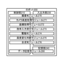
- FIG. 3 is a functional block diagram of the robot 200.
- FIG. 4 is a flowchart showing altitude change processing executed by the robot 200.
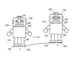
- FIG. 5 is a diagram illustrating a state in which the robot 200 has adjusted the altitude.
- FIG. 1 is a diagram for explaining the outline of an omnidirectional camera robot altitude adjustment system 1 which is a preferred embodiment of the present invention.
- the omnidirectional camera robot altitude adjustment system 1 includes a robot 200.
- the number of robots 200 is not limited to one and may be plural.
- the robot 200 may be realized by either or both of an actual device and a virtual device.
- the robot 200 is a machine that accepts a continuous or random automatic operation or an instruction from a user autonomously and performs an action based on the instruction. You may receive the instruction input from the information terminal which is not illustrated.
- the robot 200 includes a trunk composed of a head 340, a neck 350, and a torso, and a limb composed of upper and lower limbs 300 and 310.
- the head 340 has a mounting portion 360 on which the omnidirectional camera 100 is mounted.
- Rollers 320 and 330 are provided at the bottom of the lower limb 310.
- the robot 200 performs rotation, movement, and the like by driving the lower limbs 300 and 310 or the rollers 320 and 330.
- the robot 200 changes the altitude of the omnidirectional camera 100 by driving the mounting unit 360. Further, the robot 200 changes the altitude of the omnidirectional camera 100 by changing the length of the neck portion 350. Note that the robot 200 may move by driving a part other than the part described above, or may change the altitude of the omnidirectional camera 100 or may change its own altitude. Good.
- the omnidirectional camera 100 is an imaging device such as a camera combined with a plurality of cameras or a camera equipped with a plurality of special lenses.
- the omnidirectional camera 100 captures all directions of up, down, left, and right, and captures a 360-degree panoramic image as a full-field image.
- the omnidirectional camera 100 may be configured to capture a plurality of images in all directions from a certain point and create a full-field image by synthesizing the captured images.
- the robot 200 receives an imaging instruction input and captures a full-field image by the omnidirectional camera 100 (step S01).
- the robot 200 may be configured to always capture a full-field image, or receives an instruction input from an information terminal (not shown) or an instruction input to an input unit that receives an input (not shown).
- the configuration may be such that imaging is performed by
- the robot 200 When the robot 200 receives an input of a movement instruction, the robot 200 acquires the altitude of the omnidirectional camera 100 at the current location A and moves to the destination point B designated by the movement instruction (step S02). The robot 200 acquires the altitude of the omnidirectional camera 100 using an altitude sensor or the like provided in the omnidirectional camera 100. Further, the robot 200 moves to a designated point by driving the rollers 320 and 330. Note that the robot 200 may acquire the omnidirectional camera 100 and its altitude by a method other than the altitude sensor. The robot 200 may move to a designated point by driving the lower limbs 300 and 310, or may move according to other configurations.
- the robot 200 acquires the altitude of the omnidirectional camera 100 after moving (step S03).
- the robot 200 compares the altitude of the omnidirectional camera 100 before movement with the altitude of the omnidirectional camera 100 after movement, and determines whether or not there is a change in altitude. When it is determined that there is a change in altitude, the robot 200 adjusts the altitude of the omnidirectional camera 100 by changing the altitude of the omnidirectional camera 100 or its own altitude (step S04). In step S04, the robot 200 may adjust the altitude of the omnidirectional camera 100 by driving the mounting unit 360 on which the omnidirectional camera 100 is mounted, or by changing the altitude of the neck 350. The altitude of the omnidirectional camera 100 may be adjusted.
- the robot 200 may be provided with an altitude sensor or the like at the bottom of the lower limbs 300 and 310. In this case, the robot 200 acquires the coordinates of the two provided points, and calculates the altitude of the omnidirectional camera 100 from the coordinates of the two points and the angle connecting the two points and the omnidirectional camera 100. To do. The robot 200 may execute the process of step S04 described above based on the calculated altitude.
- FIG. 2 is a diagram showing a system configuration of the omnidirectional camera robot altitude adjustment system 1 which is a preferred embodiment of the present invention.
- the omnidirectional camera robot altitude adjustment system 1 includes a robot 200. Note that the robot 200 is not limited to one and may be a plurality. The robot 200 may be realized by a real device or a virtual device.
- the robot 200 is the above-described machine having the functions described later.
- the omnidirectional camera 100 and the robot 200 may be separate.
- the omnidirectional camera 100 and the robot 200 may be connected via a wired connection, short-range wireless communication, infrared communication, a public line network, or the like.
- the robot 200 is composed of a trunk and limbs as described above.
- the mounting unit 360 changes the altitude and position of the omnidirectional camera 100 by driving the omnidirectional camera 100 mounted in the front, rear, up, down, left, and right directions using a motor or the like.
- the robot 200 moves by driving the lower limbs 300 and 310 and performing a bending and stretching operation.
- the robot 200 moves or rotates by driving the rollers 320 and 330. Note that the robot 200 may move by driving a part other than the parts described above or the whole, or may change the altitude or position of the omnidirectional camera 100.
- FIG. 3 is a functional block diagram of the robot 200.
- the robot 200 includes a CPU (Central Processing Unit), a RAM (Random Access Memory), a ROM (Read Only Memory), etc. as the control unit 210, and a device for enabling communication with other devices as a communication unit, for example, , A device compatible with WiFi (Wireless Fidelity) compliant with IEEE 802.11.
- a CPU Central Processing Unit
- RAM Random Access Memory
- ROM Read Only Memory
- the robot 200 serves as an input / output unit 230, such as a display unit that outputs and displays data and images controlled by the control unit 210, an input unit such as a touch panel, a keyboard, and a mouse that accepts input from a user, Alternatively, a driving device such as a motor that drives the whole, an altitude detecting device such as a sensor that detects the altitude of the omnidirectional camera 100, and the like are provided.
- the robot 200 includes a data storage unit such as a hard disk, a semiconductor memory, a recording medium, or a memory card as the storage unit 240.
- the control unit 210 when the control unit 210 reads a predetermined program, the imaging module 270, the camera height acquisition module 271, the coordinate acquisition module 272, the instruction input reception module 273, and the drive module 274 cooperate with the input / output unit 230.
- the altitude change determination module 275 and the synthesis module 276 are realized.
- the control unit 210 reads a predetermined program, thereby realizing the data storage module 280 in cooperation with the storage unit 240.
- FIG. 4 is a diagram showing a flowchart of altitude adjustment processing executed by the robot 200. Processing executed by each module described above will be described together with this processing.
- the imaging module 270 receives an imaging instruction and captures a full-field image (step S10).
- step S ⁇ b> 10 the imaging module 270 activates a dedicated application by an information terminal (not shown) and transmits an imaging instruction input, or inputs an imaging switch provided in the omnidirectional camera 100 or the robot 200.
- a full-field image is picked up based on accepting.
- the imaging module 270 captures an image such as a moving image or a still image as a full-field image.
- the full-field image is an image having 360 degrees in all directions. Note that the imaging module 270 may accept an input of an imaging instruction other than the example described above.
- the camera altitude acquisition module 271 acquires the current altitude of the omnidirectional camera 100 (step S11). In step S11, the camera altitude acquisition module 271 acquires the current altitude using a sensor or the like based on its own atmospheric pressure, GPS, or the like.
- the coordinate acquisition module 272 is provided at two points on the bottom of the lower limb 300 and the bottom of the lower limb 310. From the coordinates of the two points and the angle between the two points and the omnidirectional camera 100, The current altitude of the omnidirectional camera 100 may be calculated. A coordinate is the length of the side connected between these two points. The coordinate acquisition module 272 calculates the altitude of the omnidirectional camera 100 by triangulation. In addition, the coordinates may be a set of numbers based on the distance from the center of gravity of each point, or may have other configurations.
- the coordinate acquisition module 272 only needs to be provided at least at two points, and the location is not limited to the example described above, and may be another location, and the number thereof can be changed as appropriate.
- the data storage module 280 stores the image data of the entire visual field image captured in step S10 in association with the current altitude acquired in step S11 (step S12).
- the instruction input reception module 273 determines whether or not an instruction input for moving, changing the position of the omnidirectional camera 100, or the like has been received (step S13).
- step S ⁇ b> 13 the instruction input reception module 273 performs an input to move the robot 200 to a predetermined point using an information terminal (not shown), an input to change the position of the omnidirectional camera 100 to a predetermined point, or a touch panel. The determination is made based on whether or not an input to move to a predetermined point is accepted by using a keyboard or the like.
- step S13 when the instruction input receiving module 273 determines that the instruction input is not received (NO in step S13), the process is repeated.
- step S13 when the instruction input receiving module 273 determines in step S13 that the instruction has been received (YES in step S13), the drive module 274 drives a part or all of the robot 200 based on the instruction to Move (step S14).
- step S14 the drive module 274 rotates the rollers 320 and 330, whereby the robot 200 moves.
- the drive module 274 may drive part or all of the other robots 200 to move the robots 200.
- the camera altitude acquisition module 271 acquires the altitude after the movement of the omnidirectional camera 100 (step S15).
- step S15 the camera altitude acquisition module 271 is the same as the processing in step S11 described above, and thus the details are omitted.
- the altitude change determination module 275 compares the altitude of the omnidirectional camera 100 before movement stored in the data storage module 280 with the altitude of the omnidirectional camera 100 after movement, and determines whether or not there is a change in altitude. Is determined (step S16). In step S16, the altitude change determination module 275 may determine that no change has occurred if the altitude change is within a predetermined threshold even if the altitude change has occurred. .
- the predetermined threshold is, for example, several mm, 1 cm, or 2 cm. This threshold value can be changed as appropriate.
- step S16 if the altitude change determination module 275 determines that no altitude change has occurred (NO in step S16), the process ends.
- step S16 determines in step S16 that the altitude change has occurred (step S16 YES)
- the drive module 274 causes the omnidirectional camera 100 to keep the altitude change constant.
- the altitude is adjusted (step S17).
- step S ⁇ b> 17 the drive module 274 adjusts the altitude of the omnidirectional camera 100 by driving the mounting unit 360.
- step S ⁇ b> 17 the drive module 274 adjusts the altitude of the omnidirectional camera 100 by driving the neck 350, changing its length, and adjusting the altitude of the robot 200.
- the drive module 274 is not limited to the example described above, and may drive a part or all of the other robot 200 to adjust the altitude of the omnidirectional camera 100. And the altitude of the omnidirectional camera 100 may be adjusted.
- a coordinate acquisition module 272 is provided at two points on the bottom of the lower limb 300 and the bottom of the lower limb 310.
- the current altitude of the celestial camera 100 may be calculated.
- a coordinate is the length of the side connected between these two points.
- the coordinate acquisition module 272 calculates the altitude of the omnidirectional camera 100 by triangulation.
- the coordinates may be a set of numbers based on the distance from the center of gravity of each point, or may have other configurations. Processing described below may be performed based on the altitude of the omnidirectional camera 100 calculated in this way.
- the coordinate acquisition module 272 only needs to be provided at least at two points, and the location is not limited to the example described above, and may be another location, and the number thereof can be changed as appropriate.
- FIG. 5 is a diagram illustrating a state in which the robot 200 executes the processes of steps S14 to S17 described above.
- the robot 200 will be described as moving from the current point C to the destination point D.
- the current point C is lower than the destination point D.
- the robot 200 receives a movement instruction to the destination point D, drives the rollers 320 and 330, and moves from the current point C to the destination point D.
- the robot 200 compares the altitude of the omnidirectional camera 100 stored at the current location C with the altitude of the omnidirectional camera 100 acquired at the destination location D, and calculates the amount of change. In FIG. 5, the robot 200 lowers the altitude of the omnidirectional camera 100 in order to keep the amount of change in altitude constant.
- the robot 200 drives the mounting unit 360 to lower the altitude of the omnidirectional camera 100, and substantially reduces the altitude of the omnidirectional camera 100 at the current location C and the altitude of the omnidirectional camera 100 at the destination location D. Adjust to an equal value.
- the imaging module 270 captures a full-field image at the destination point (step S18).
- the synthesizing module 276 synthesizes the stored image data of the entire visual field image at the current position and the image data of the entire visual field image at the movement destination point within a predetermined error range to create one image (step S19).
- the synthesis module 276 recognizes the stored full-field image at the current location and the entire visual-field image at the destination location, and synthesizes them by superimposing the matching parts to create one image.
- “within a predetermined error range” indicates that synthesis may be performed not only in a completely matched state but also in a slightly shifted state.
- the synthesis module 276 may synthesize a plurality of image data by other methods.
- the means and functions described above are realized by a computer (including a CPU, an information processing apparatus, and various terminals) reading and executing a predetermined program.
- the program is provided in a form recorded on a computer-readable recording medium such as a flexible disk, CD (CD-ROM, etc.), DVD (DVD-ROM, DVD-RAM, etc.).
- the computer reads the program from the recording medium, transfers it to the internal storage device or the external storage device, stores it, and executes it.
- the program may be recorded in advance in a storage device (recording medium) such as a magnetic disk, an optical disk, or a magneto-optical disk, and provided from the storage device to a computer via a communication line.
Landscapes
- Engineering & Computer Science (AREA)
- Physics & Mathematics (AREA)
- General Physics & Mathematics (AREA)
- Multimedia (AREA)
- Signal Processing (AREA)
- Robotics (AREA)
- Mechanical Engineering (AREA)
- Studio Devices (AREA)
- Control Of Position, Course, Altitude, Or Attitude Of Moving Bodies (AREA)
- Stereoscopic And Panoramic Photography (AREA)
- Theoretical Computer Science (AREA)
- Life Sciences & Earth Sciences (AREA)
- Evolutionary Computation (AREA)
- Artificial Intelligence (AREA)
- Biomedical Technology (AREA)
- Biophysics (AREA)
- Computational Linguistics (AREA)
- Data Mining & Analysis (AREA)
- Health & Medical Sciences (AREA)
- General Health & Medical Sciences (AREA)
- Molecular Biology (AREA)
- Computing Systems (AREA)
- General Engineering & Computer Science (AREA)
- Mathematical Physics (AREA)
- Software Systems (AREA)
- Manipulator (AREA)
Abstract
Description
前記全天球カメラの高度を取得する高度取得手段と、
前記取得した高度が一定になるように、前記ロボットの高度を調整する高度調整手段と、
前記全天球カメラの360度撮像画像を、所定の高度誤差範囲内で合成処理により作成する合成画像作成手段と、
を備えることを特徴とする全天球カメラロボット高度調整システムを提供する。
前記取得した2点の座標と、当該2点と全天球カメラとを結ぶ角度とから、前記全天球カメラの高度を計算する高度計算手段と、
を備えることを特徴とする第1の特徴に係る発明である全天球カメラロボット高度調整システムを提供する。
ことを特徴とする第2の特徴に係る発明である全天球カメラロボット高度調整システムを提供する。
前記全天球カメラの高度を取得するステップと、
前記取得した高度が一定になるように、前記ロボットの高度を調整するステップと、
前記全天球カメラの360度撮像画像を、所定の高度誤差範囲内で合成処理により作成するステップと、
を備えることを特徴とする全天球カメラロボット高度調整方法を提供する。
前記全天球カメラの高度を取得するステップ、
前記取得した高度が一定になるように、前記ロボットの高度を調整するステップ、
前記全天球カメラの360度撮像画像を、所定の高度誤差範囲内で合成処理により作成するステップ、
を実行させることを特徴とするプログラムを提供する。
本発明の好適な実施形態である全天球カメラロボット高度調整システム1の概要について、図1に基づいて説明する。図1は、本発明の好適な実施形態である全天球カメラロボット高度調整システム1の概要を説明するための図である。全天球カメラロボット高度調整システム1は、ロボット200から構成される。
図2に基づいて、本発明の好適な実施形態である全天球カメラロボット高度調整システム1のシステム構成について説明する。図2は、本発明の好適な実施形態である全天球カメラロボット高度調整システム1のシステム構成を示す図である。全天球カメラロボット高度調整システム1は、ロボット200から構成される。なお、ロボット200は、1つに限らず複数であってもよい。また、ロボット200は、実在する装置又は仮想的な装置により実現されてもよい。
図3に基づいて、本発明の好適な実施形態である全天球カメラロボット高度調整システム1の機能について説明する。図3は、ロボット200の機能ブロック図である。
図4に基づいて、ロボット200が実行する高度調整処理について説明する。図4は、ロボット200が実行する高度調整処理のフローチャートを示す図である。上述した各モジュールが実行する処理について、本処理に併せて説明する。
Claims (5)
- 全天球カメラが備えられたロボットの高度を調整する全天球カメラロボット高度調整システムであって、
前記全天球カメラの高度を取得する高度取得手段と、
前記取得した高度が一定になるように、前記ロボットの高度を調整する高度調整手段と、
前記全天球カメラの360度撮像画像を、所定の高度誤差範囲内で合成処理により作成する合成画像作成手段と、
を備えることを特徴とする全天球カメラロボット高度調整システム。 - 前記ロボットの少なくとも2点に備えられ、当該少なくとも2点の座標を取得する座標取得手段と、
前記取得した2点の座標と、当該2点と全天球カメラとを結ぶ角度とから、前記全天球カメラの高度を計算する高度計算手段と、
を備えることを特徴とする請求項1に記載の全天球カメラロボット高度調整システム。 - 前記高度調整手段は、前記高度計算手段で計算された高度から、前記全天球カメラの高度の調整を更に行う、
ことを特徴とする請求項2に記載の全天球カメラロボット高度調整システム。 - 全天球カメラが備えられたロボットの高度を調整する全天球カメラロボット高度調整方法であって、
前記全天球カメラの高度を取得するステップと、
前記取得した高度が一定になるように、前記ロボットの高度を調整するステップと、
前記全天球カメラの360度撮像画像を、所定の高度誤差範囲内で合成処理により作成するステップと、
を備えることを特徴とする全天球カメラロボット高度調整方法。 - 全天球カメラが備えられたロボットの高度を調整する全天球カメラロボット高度調整システムに、
前記全天球カメラの高度を取得するステップ、
前記取得した高度が一定になるように、前記ロボットの高度を調整するステップ、
前記全天球カメラの360度撮像画像を、所定の高度誤差範囲内で合成処理により作成するステップ、
を実行させることを特徴とするプログラム。
Priority Applications (3)
| Application Number | Priority Date | Filing Date | Title |
|---|---|---|---|
| JP2016567950A JP6200604B1 (ja) | 2016-04-12 | 2016-04-12 | 全天球カメラロボット高度調整システム、全天球カメラロボット高度調整方法及びプログラム |
| PCT/JP2016/061848 WO2017179136A1 (ja) | 2016-04-12 | 2016-04-12 | 全天球カメラロボット高度調整システム、全天球カメラロボット高度調整方法及びプログラム |
| US15/319,882 US10792817B2 (en) | 2016-04-12 | 2016-04-12 | System, method, and program for adjusting altitude of omnidirectional camera robot |
Applications Claiming Priority (1)
| Application Number | Priority Date | Filing Date | Title |
|---|---|---|---|
| PCT/JP2016/061848 WO2017179136A1 (ja) | 2016-04-12 | 2016-04-12 | 全天球カメラロボット高度調整システム、全天球カメラロボット高度調整方法及びプログラム |
Publications (1)
| Publication Number | Publication Date |
|---|---|
| WO2017179136A1 true WO2017179136A1 (ja) | 2017-10-19 |
Family
ID=59895633
Family Applications (1)
| Application Number | Title | Priority Date | Filing Date |
|---|---|---|---|
| PCT/JP2016/061848 Ceased WO2017179136A1 (ja) | 2016-04-12 | 2016-04-12 | 全天球カメラロボット高度調整システム、全天球カメラロボット高度調整方法及びプログラム |
Country Status (3)
| Country | Link |
|---|---|
| US (1) | US10792817B2 (ja) |
| JP (1) | JP6200604B1 (ja) |
| WO (1) | WO2017179136A1 (ja) |
Cited By (1)
| Publication number | Priority date | Publication date | Assignee | Title |
|---|---|---|---|---|
| US11212439B2 (en) | 2018-07-24 | 2021-12-28 | Ricoh Company, Ltd. | Communication terminal, display method, and non-transitory computer-readable medium for displaying images and controller |
Families Citing this family (4)
| Publication number | Priority date | Publication date | Assignee | Title |
|---|---|---|---|---|
| EP3738725B1 (en) * | 2019-05-15 | 2022-02-16 | Omron Corporation | Measurement system, measurement device, measurement method, and measurement program |
| KR20230048072A (ko) * | 2020-08-06 | 2023-04-10 | 피아지오 패스트 포워드 인코포레이티드 | 페어 모드 및 스마트 거동 모드를 갖는 에티켓-기반 차량 및 이를 위한 제어 시스템들 |
| CN112389686B (zh) * | 2020-11-24 | 2022-06-07 | 西北工业大学深圳研究院 | 一种基于空间多臂接触的被动目标同步消旋抓捕操作方法 |
| CN116372916A (zh) * | 2023-03-20 | 2023-07-04 | 山东新一代信息产业技术研究院有限公司 | 一种巡检机器人拍摄控制方法、系统、装置和存储介质 |
Citations (2)
| Publication number | Priority date | Publication date | Assignee | Title |
|---|---|---|---|---|
| JP2006185438A (ja) * | 2004-12-03 | 2006-07-13 | Matsushita Electric Ind Co Ltd | ロボット制御装置 |
| JP2007225809A (ja) * | 2006-02-22 | 2007-09-06 | Nippon Hoso Kyokai <Nhk> | カメラ雲台付き移動台車 |
Family Cites Families (8)
| Publication number | Priority date | Publication date | Assignee | Title |
|---|---|---|---|---|
| JP4119529B2 (ja) * | 1998-06-17 | 2008-07-16 | オリンパス株式会社 | 仮想環境生成方法および装置、並びに仮想環境生成プログラムを記録した記録媒体 |
| JP3889650B2 (ja) * | 2002-03-28 | 2007-03-07 | 三洋電機株式会社 | 画像処理方法、画像処理装置、コンピュータプログラム、及び記録媒体 |
| US20100222925A1 (en) * | 2004-12-03 | 2010-09-02 | Takashi Anezaki | Robot control apparatus |
| KR100988960B1 (ko) * | 2008-04-23 | 2010-10-20 | 한국도로공사 | 장애물 승월이 가능한 교량점검용 로봇 |
| WO2013121897A1 (ja) * | 2012-02-17 | 2013-08-22 | ソニー株式会社 | 情報処理装置および方法、画像処理装置および方法、並びにプログラム |
| JP2013214947A (ja) * | 2012-03-09 | 2013-10-17 | Ricoh Co Ltd | 撮像装置、撮像システム、画像処理方法、情報処理装置、及びプログラム |
| US20140152765A1 (en) * | 2012-12-05 | 2014-06-05 | Samsung Electronics Co., Ltd. | Imaging device and method |
| US10084960B2 (en) * | 2014-10-10 | 2018-09-25 | Iec Infrared Systems, Llc | Panoramic view imaging system with drone integration |
-
2016
- 2016-04-12 US US15/319,882 patent/US10792817B2/en active Active
- 2016-04-12 JP JP2016567950A patent/JP6200604B1/ja active Active
- 2016-04-12 WO PCT/JP2016/061848 patent/WO2017179136A1/ja not_active Ceased
Patent Citations (2)
| Publication number | Priority date | Publication date | Assignee | Title |
|---|---|---|---|---|
| JP2006185438A (ja) * | 2004-12-03 | 2006-07-13 | Matsushita Electric Ind Co Ltd | ロボット制御装置 |
| JP2007225809A (ja) * | 2006-02-22 | 2007-09-06 | Nippon Hoso Kyokai <Nhk> | カメラ雲台付き移動台車 |
Cited By (3)
| Publication number | Priority date | Publication date | Assignee | Title |
|---|---|---|---|---|
| US11212439B2 (en) | 2018-07-24 | 2021-12-28 | Ricoh Company, Ltd. | Communication terminal, display method, and non-transitory computer-readable medium for displaying images and controller |
| US12075167B2 (en) | 2018-07-24 | 2024-08-27 | Ricoh Company, Ltd. | Communication terminal, display method, and non-transitory computer-readable medium for displaying images and controller |
| US12483795B2 (en) | 2018-07-24 | 2025-11-25 | Ricoh Company, Ltd. | Communication terminal, display method, and non-transitory computer-readable medium for displaying videos captured by telepresence robot |
Also Published As
| Publication number | Publication date |
|---|---|
| JPWO2017179136A1 (ja) | 2018-04-19 |
| US20180354138A1 (en) | 2018-12-13 |
| JP6200604B1 (ja) | 2017-09-20 |
| US10792817B2 (en) | 2020-10-06 |
Similar Documents
| Publication | Publication Date | Title |
|---|---|---|
| CN114761909B (zh) | 头戴式设备及调整对虚拟内容项的渲染的方法 | |
| US9401050B2 (en) | Recalibration of a flexible mixed reality device | |
| US11164378B1 (en) | Virtual reality detection and projection system for use with a head mounted display | |
| JP4825980B2 (ja) | 魚眼カメラの校正方法。 | |
| US8255462B2 (en) | Information processing system and information processing apparatus | |
| US20200342830A1 (en) | Method and system of wireless data transmission for virtual or augmented reality head mounted displays | |
| CN106575437B (zh) | 信息处理装置、信息处理方法以及程序 | |
| US11769258B2 (en) | Feature processing in extended reality systems | |
| TWI642903B (zh) | 用於頭戴式顯示裝置的定位方法、定位器以及定位系統 | |
| JP6200604B1 (ja) | 全天球カメラロボット高度調整システム、全天球カメラロボット高度調整方法及びプログラム | |
| JP2019536170A (ja) | 仮想的に拡張された視覚的同時位置特定及びマッピングのシステム及び方法 | |
| JP2006059202A (ja) | 撮像装置及び画像補正方法 | |
| KR102404867B1 (ko) | 3차원 거리정보를 이용한 랩어라운드뷰 영상제공장치 및 방법 | |
| US11847784B2 (en) | Image processing apparatus, head-mounted display, and method for acquiring space information | |
| WO2025006353A1 (en) | Head mounted display (hmd) device calibration based on hinge motion | |
| JP6890524B2 (ja) | 姿勢制御システム | |
| JP2017227957A (ja) | 情報処理装置、および、情報処理システム | |
| US9445015B2 (en) | Methods and systems for adjusting sensor viewpoint to a virtual viewpoint | |
| EP3242471B1 (en) | Camera having multiple imaging sensors | |
| KR102923256B1 (ko) | 전자 장치, 이를 이용한 스테레오 영상 복원 방법 및 컴퓨터로 읽을 수 있는 기록 매체 | |
| US12450855B2 (en) | Visual alignment of displayed virtual content | |
| US12572197B2 (en) | Hand tracking and power optimization for extended reality (XR) systems | |
| US20240386532A1 (en) | Jitter estimation using physical constraints | |
| EP3616400B1 (en) | Method for providing content and apparatus therefor | |
| JP2025035059A (ja) | 画像処理システム、移動体、画像処理方法、及びコンピュータプログラム |
Legal Events
| Date | Code | Title | Description |
|---|---|---|---|
| ENP | Entry into the national phase |
Ref document number: 2016567950 Country of ref document: JP Kind code of ref document: A |
|
| NENP | Non-entry into the national phase |
Ref country code: DE |
|
| 121 | Ep: the epo has been informed by wipo that ep was designated in this application |
Ref document number: 16898596 Country of ref document: EP Kind code of ref document: A1 |
|
| 32PN | Ep: public notification in the ep bulletin as address of the adressee cannot be established |
Free format text: NOTING OF LOSS OF RIGHTS PURSUANT TO RULE 112(1) EPC (EPO FORM 1205A DATED 21.01.2019) |
|
| 122 | Ep: pct application non-entry in european phase |
Ref document number: 16898596 Country of ref document: EP Kind code of ref document: A1 |