WO2017177440A1 - 状态指示的传输装置、方法以及通信系统 - Google Patents
状态指示的传输装置、方法以及通信系统 Download PDFInfo
- Publication number
- WO2017177440A1 WO2017177440A1 PCT/CN2016/079424 CN2016079424W WO2017177440A1 WO 2017177440 A1 WO2017177440 A1 WO 2017177440A1 CN 2016079424 W CN2016079424 W CN 2016079424W WO 2017177440 A1 WO2017177440 A1 WO 2017177440A1
- Authority
- WO
- WIPO (PCT)
- Prior art keywords
- user equipment
- information
- downlink control
- physical downlink
- control channel
- Prior art date
- Legal status (The legal status is an assumption and is not a legal conclusion. Google has not performed a legal analysis and makes no representation as to the accuracy of the status listed.)
- Ceased
Links
Images




Classifications
-
- H—ELECTRICITY
- H04—ELECTRIC COMMUNICATION TECHNIQUE
- H04L—TRANSMISSION OF DIGITAL INFORMATION, e.g. TELEGRAPHIC COMMUNICATION
- H04L1/00—Arrangements for detecting or preventing errors in the information received
- H04L1/12—Arrangements for detecting or preventing errors in the information received by using return channel
- H04L1/16—Arrangements for detecting or preventing errors in the information received by using return channel in which the return channel carries supervisory signals, e.g. repetition request signals
- H04L1/1607—Details of the supervisory signal
- H04L1/1671—Details of the supervisory signal the supervisory signal being transmitted together with control information
-
- H—ELECTRICITY
- H04—ELECTRIC COMMUNICATION TECHNIQUE
- H04L—TRANSMISSION OF DIGITAL INFORMATION, e.g. TELEGRAPHIC COMMUNICATION
- H04L5/00—Arrangements affording multiple use of the transmission path
- H04L5/003—Arrangements for allocating sub-channels of the transmission path
- H04L5/0053—Allocation of signalling, i.e. of overhead other than pilot signals
-
- H—ELECTRICITY
- H04—ELECTRIC COMMUNICATION TECHNIQUE
- H04W—WIRELESS COMMUNICATION NETWORKS
- H04W24/00—Supervisory, monitoring or testing arrangements
- H04W24/10—Scheduling measurement reports ; Arrangements for measurement reports
-
- H—ELECTRICITY
- H04—ELECTRIC COMMUNICATION TECHNIQUE
- H04W—WIRELESS COMMUNICATION NETWORKS
- H04W28/00—Network traffic management; Network resource management
- H04W28/02—Traffic management, e.g. flow control or congestion control
- H04W28/06—Optimizing the usage of the radio link, e.g. header compression, information sizing, discarding information
-
- H—ELECTRICITY
- H04—ELECTRIC COMMUNICATION TECHNIQUE
- H04W—WIRELESS COMMUNICATION NETWORKS
- H04W52/00—Power management, e.g. Transmission Power Control [TPC] or power classes
- H04W52/02—Power saving arrangements
- H04W52/0209—Power saving arrangements in terminal devices
- H04W52/0212—Power saving arrangements in terminal devices managed by the network, e.g. network or access point is leader and terminal is follower
- H04W52/0216—Power saving arrangements in terminal devices managed by the network, e.g. network or access point is leader and terminal is follower using a pre-established activity schedule, e.g. traffic indication frame
-
- H—ELECTRICITY
- H04—ELECTRIC COMMUNICATION TECHNIQUE
- H04W—WIRELESS COMMUNICATION NETWORKS
- H04W52/00—Power management, e.g. Transmission Power Control [TPC] or power classes
- H04W52/02—Power saving arrangements
- H04W52/0209—Power saving arrangements in terminal devices
- H04W52/0225—Power saving arrangements in terminal devices using monitoring of external events, e.g. the presence of a signal
- H04W52/0229—Power saving arrangements in terminal devices using monitoring of external events, e.g. the presence of a signal where the received signal is a wanted signal
-
- H—ELECTRICITY
- H04—ELECTRIC COMMUNICATION TECHNIQUE
- H04W—WIRELESS COMMUNICATION NETWORKS
- H04W76/00—Connection management
- H04W76/20—Manipulation of established connections
- H04W76/28—Discontinuous transmission [DTX]; Discontinuous reception [DRX]
-
- H—ELECTRICITY
- H04—ELECTRIC COMMUNICATION TECHNIQUE
- H04W—WIRELESS COMMUNICATION NETWORKS
- H04W72/00—Local resource management
- H04W72/20—Control channels or signalling for resource management
- H04W72/23—Control channels or signalling for resource management in the downlink direction of a wireless link, i.e. towards a terminal
-
- Y—GENERAL TAGGING OF NEW TECHNOLOGICAL DEVELOPMENTS; GENERAL TAGGING OF CROSS-SECTIONAL TECHNOLOGIES SPANNING OVER SEVERAL SECTIONS OF THE IPC; TECHNICAL SUBJECTS COVERED BY FORMER USPC CROSS-REFERENCE ART COLLECTIONS [XRACs] AND DIGESTS
- Y02—TECHNOLOGIES OR APPLICATIONS FOR MITIGATION OR ADAPTATION AGAINST CLIMATE CHANGE
- Y02D—CLIMATE CHANGE MITIGATION TECHNOLOGIES IN INFORMATION AND COMMUNICATION TECHNOLOGIES [ICT], I.E. INFORMATION AND COMMUNICATION TECHNOLOGIES AIMING AT THE REDUCTION OF THEIR OWN ENERGY USE
- Y02D30/00—Reducing energy consumption in communication networks
- Y02D30/70—Reducing energy consumption in communication networks in wireless communication networks
Definitions
- the present invention relates to the field of communications, and in particular, to a transmission apparatus, method, and communication system for status indication.
- NB-IoT Narrow Band Internet of Things
- the IoT service has many new features, including ultra-low power requirements, deployment of massive user equipment, low data traffic, and low business latency requirements. These features impose many technical requirements on the Long Term Evolution (LTE) system, and important requirements include the ultra-low energy requirements of user equipment.
- LTE Long Term Evolution
- NB-IoT technology is a new narrowband communication technology based on the existing LTE technology to further enhance the IoT service requirements.
- the Medium Access Control (MAC) layer uses asynchronous transmission, and the feedback information of the uplink transmission is indicated by the scheduling information of the Physical Downlink Control Channel (PDCCH). .
- PDCH Physical Downlink Control Channel
- the user equipment For example, if the user equipment (UE, User Equipment) receives the PDCCH scheduling new data after transmitting the uplink data, it indicates that the uplink data transmission is successful. If the user equipment receives the PDCCH for scheduling retransmission, it indicates that the uplink data transmission fails, and the MAC layer retransmission is required.
- the deactivation timer For a user equipment configured with Discontinuous Reception (DRX), the deactivation timer (drx-InactivityTimer) is started after receiving the PDCCH scheduling new data. The user equipment enters the DRX state only when the drx-InactivityTimer times out or receives a discontinuous reception command (DRX Command) sent by the network side to reduce power consumption.
- DRX Command discontinuous reception command
- the radio link control (RLC) layer of the user equipment determines whether the uplink data is successfully received through the status report (SR, Status Report) fed back by the receiving end. .
- the sender only carries a poll bit in the last uplink data to indicate that the data is the last data. After receiving the last uplink data, the receiving end indicates to the sending end that the uplink data has been successfully received in the form of an RLC status report, or indicates that the data has been lost.
- the inventors have found that in, for example, the NB-IoT system, most applications have a small amount of uplink data and can be carried by one RLC Protocol Data Unit (PDU). Normally, the RLC PDU can be successfully sent through a Hybrid Automatic Repeat reQuest (HARQ) mechanism of one or more MAC PDUs. At this time, the RLC status report fed back by the receiving end does not need to indicate which data is lost, and only 1 bit of information is needed to indicate that the uplink data of the user equipment is successfully received.
- HARQ Hybrid Automatic Repeat reQuest
- the user equipment needs to receive the RLC status report in addition to the uplink data, and the RLC status report only indicates 1-bit information that is successfully received, so that the transmission efficiency of the entire system is low.
- the user equipment after the user equipment sends all the uplink data, even if there is no downlink data to be received, it still needs to continue to monitor the PDCCH, and wait for the drx-InactivityTimer to time out before entering the more energy-saving DRX state, so that the user equipment has higher energy consumption. .
- Embodiments of the present invention provide a transmission apparatus, method, and communication system for status indication.
- the PDCCH information indicates that the uplink data of the user equipment is successfully received and/or allows the user equipment to enter the DRX state, which not only improves the transmission efficiency of the entire system, but also reduces the power consumption of the user equipment.
- a method for transmitting a status indication including:
- the base station When the base station receives the uplink data sent by the user equipment, determining whether the radio link control layer successfully receives all the radio link control protocol data units of the uplink data;
- a transmission apparatus for status indication which is configured in a base station, and the transmission apparatus includes:
- a receiving determining unit when the base station receives the uplink data sent by the user equipment, determining whether the radio link control layer successfully receives all the radio link control protocol data units of the uplink data;
- An information sending unit that transmits physical downlink control channel information to the user equipment when the radio link control layer successfully receives all radio link control protocol data units of the uplink data; wherein the physical downlink control The channel information is used to indicate that the uplink data has been successfully received and/or allow the user equipment to enter a discontinuous reception state.
- a method for transmitting a status indication includes:
- the user equipment listens to the physical downlink control channel after transmitting the uplink data.
- a transmission device for status indication which is configured in a user equipment, and the transmission device includes:
- a channel monitoring unit which monitors a physical downlink control channel after the user equipment sends uplink data
- An information receiving unit configured to receive physical downlink control channel information that is sent by the base station by using the physical downlink control channel, where the physical downlink control channel information is used to indicate that the uplink data has been successfully received and/or the user equipment is allowed to enter the non- Continuous reception status.
- a communication system comprising:
- a base station comprising the transmission device of the second aspect
- User equipment comprising the transmission device of the fourth aspect.
- the beneficial effects of the embodiment of the present invention are: indicating that the uplink data of the user equipment is successfully received by the PDCCH information and/or allowing the user equipment to enter the DRX state, not only reducing the transmission of the RLC status report, but also improving the transmission efficiency of the entire system, and Enable the user equipment to enter the DRX state as soon as possible, reducing the energy consumption of the user equipment.
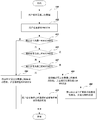
- FIG. 1 is a schematic diagram of a transmission method of a status indication according to Embodiment 1 of the present invention.
- FIG. 2 is another schematic diagram of a transmission method of a status indication according to Embodiment 1 of the present invention.
- FIG. 3 is another schematic diagram of a transmission method of a status indication according to Embodiment 1 of the present invention.
- FIG. 4 is another schematic diagram of a transmission method of a status indication according to Embodiment 1 of the present invention.
- FIG. 5 is a schematic diagram of a transmission method of a status indication according to Embodiment 2 of the present invention.
- FIG. 6 is another schematic diagram of a transmission method of a status indication according to Embodiment 2 of the present invention.
- Figure 7 is a schematic diagram of a transmission apparatus for status indication according to Embodiment 3 of the present invention.
- Figure 8 is a schematic diagram of a transmission apparatus for status indication according to Embodiment 4 of the present invention.
- Figure 9 is a schematic diagram of a communication system according to Embodiment 5 of the present invention.
- Figure 10 is a schematic diagram of a base station according to Embodiment 5 of the present invention.
- FIG. 11 is a schematic diagram of a user equipment according to Embodiment 5 of the present invention.
- a base station may be referred to as an access point, a broadcast transmitter, a Node B, an evolved Node B (eNB), etc., and may include some or all of their functions.
- the term "base station” will be used herein. Each base station provides communication coverage for a particular geographic area.
- a mobile station or device may be referred to as a "user equipment” (UE).
- UE may be fixed or mobile and may also be referred to as a mobile station, terminal, access terminal, subscriber unit, station, and the like.
- the UE may be a cellular telephone, a personal digital assistant (PDA), a wireless modem, a wireless communication device, a handheld device, a laptop computer, a cordless telephone, a car, and the like.
- PDA personal digital assistant
- the embodiment of the invention provides a method for transmitting a status indication, which is described from the base station side.
- FIG. 1 is a schematic diagram of a method for transmitting a status indication according to an embodiment of the present invention. As shown in FIG. 1, the transmission method includes:
- Step 101 When receiving the uplink data sent by the user equipment, the base station determines whether the RLC layer successfully receives all the RLC PDUs of the uplink data.
- Step 102 The base station sends PDCCH information to the user equipment if the RLC layer successfully receives all the RLC PDUs of the uplink data, where the PDCCH information is used to indicate that the uplink data has been successfully received and/or the user equipment is allowed to be received. Enter the DRX state.
- the user equipment may be, for example, a terminal of the NB-IoT system, but the present invention is not limited thereto.
- the user equipment may also be a terminal of another network system.
- the embodiment of the present invention is only described by taking the NB-IoT system as an example, but is not limited thereto, and can be applied to any system that performs status indication transmission.
- the base station may be a base station of a cell to which the user equipment belongs; the base station may be a macro base station (for example, an eNB), and the user equipment is served by a macro cell (for example, a Macro cell) generated by the macro base station;
- the base station of the example may also be a micro base station, and the user equipment is served by a micro cell (for example, a Pico cell or a micro cell) generated by the micro base station.
- the embodiment of the present invention is not limited thereto, and a specific scenario may be determined according to actual needs.
- the uplink data may include one or more RLC PDUs, and when the user equipment sends the last uplink data (for example, an RLC PDU), the uplink data may carry a poll bit to notify The base station data is the last uplink data.
- the RLC layer of the base station can determine whether it is successful. All RLC PDUs of the uplink data are received.
- the RLC layer of the eNB when the RLC layer of the eNB receives the last RLC PDU of the UE, if the RLC layer successfully receives all uplink RLC PDUs of the UE, that is, there is no lost RLC PDU, the RLC layer of the eNB instructs the MAC layer to notify the UE through the PDCCH. Regarding the status information of the RLC layer data transmission, it is not necessary to send an RLC status report.
- the transmission method includes:
- Step 201 The base station receives uplink data sent by the user equipment.
- Step 202 The base station determines whether the RLC layer successfully receives all the RLC PDUs of the uplink data.
- Step 203 The base station sends PDCCH information to the user equipment.
- the base station sends the PDCCH information to the user equipment when the RLC layer successfully receives all the RLC PDUs of the uplink data, where the PDCCH information is used to indicate that the uplink data has been successfully received and/or Allow the user equipment to enter the DRX state.
- the scheme of the RLC status report may be adopted, and the related art may be referred to, and details are not described in this embodiment.
- Step 204 The user equipment continues to monitor the PDCCH or enter the DRX state according to the PDCCH information.
- the user equipment may continue to monitor the PDCCH according to the PDCCH information; In the case that all the RLC PDUs of the uplink data do not need to be transmitted for the downlink data of the user equipment, the user equipment may enter the DRX state according to the PDCCH information or enter the DRX state after performing feedback.
- the user equipment only needs low energy consumption in the DRX state.
- the user equipment may immediately enter the DRX state, or may enter the DRX state immediately after performing the feedback, or may also be after a predetermined time (for example, 1 millisecond). Entering the DRX state, or entering the DRX state immediately after other necessary operation processing; the present invention is not limited thereto, and specific processing may be performed according to actual needs.
- the eNB may directly indicate that the user equipment uplink data has been successfully received through the PDCCH, and/or allow the The user equipment enters the DRX state. Therefore, the RLC status report does not need to be sent again, and the transmission efficiency of the entire system can be improved. Moreover, the user equipment can enter the DRX state as soon as possible, and the energy consumption of the user equipment can be reduced.
- the present invention is further described below by taking three types of PDCCH information as an example.
- FIG. 3 is another schematic diagram of a method for transmitting a status indication according to an embodiment of the present invention. As shown in FIG. 3, the transmission method includes:
- Step 301 The base station receives uplink data sent by the user equipment.
- Step 302 The base station determines whether the RLC layer successfully receives all the RLC PDUs of the uplink data. If all RLC PDUs are successfully received, step 303 is performed; otherwise, step 306 is performed.
- Step 303 The base station determines whether there is a downlink data for the user equipment that needs to be transmitted. If the downlink data for the user equipment needs to be transmitted, step 304 is performed; otherwise, step 305 is performed.
- Step 304 The base station sends first PDCCH information to the user equipment, where the first PDCCH information is used to indicate that the uplink data has been successfully received.
- the successfully received message may be sent to the MAC layer. If the MAC layer of the eNB still needs to schedule or transmit downlink data for the UE, the eNB may determine and pass the physical. The layer sends the first PDCCH information, that is, the PDCCH indicating that the RLC PDU sent by the UE in the uplink has been successfully received by the PDCCH, but does not allow the UE to immediately enter the DRX state.
- Step 305 The base station sends second PDCCH information to the user equipment, where the second PDCCH information is used to indicate that the uplink data has been successfully received and the user equipment is allowed to enter a DRX state.
- the successfully received message may be notified to the MAC layer; if the MAC layer of the eNB does not need to schedule or transmit downlink data for the UE, the eNB may determine and pass the physical layer.
- the second PDCCH information is sent, that is, the RLC PDU indicating that the uplink transmission of the UE has been successfully received by the PDCCH, and the UE is allowed to enter the DRX state (for example, enters the DRX state immediately after receiving the second PDCCH information).
- Step 306 The base station uses the RLC status report to notify the user equipment of the lost uplink data information.
- the eNB detects that at least one RLC PDU is lost, it informs the UE which RLC PDUs are lost through a conventional RLC status report.
- FIG. 3 only schematically illustrates an embodiment of the present invention, but the present invention is not limited thereto.
- the order of execution between the various steps can be appropriately adjusted, and other steps can be added or some of the steps can be reduced.
- Those skilled in the art can appropriately adapt according to the above contents, and not only It is limited to the description of FIG. 3 described above.
- FIG. 4 is another schematic diagram of a method for transmitting a status indication according to an embodiment of the present invention. As shown in FIG. 4, the transmission method includes:
- Step 401 The base station receives uplink data sent by the user equipment.
- Step 402 The base station determines whether the RLC layer successfully receives all the RLC PDUs of the uplink data. If all the RLC PDUs are successfully received, step 403 is performed; otherwise, step 407 is performed.
- Step 403 The base station determines whether there is a downlink data for the user equipment that needs to be transmitted. If the downlink data for the user equipment needs to be transmitted, step 404 is performed; otherwise, step 405 is performed.
- Step 404 The base station sends first PDCCH information to the user equipment, where the first PDCCH information is used to indicate that the uplink data has been successfully received.
- the successfully received message may be sent to the MAC layer. If the MAC layer of the eNB still needs to schedule or transmit downlink data for the UE, the eNB may determine and pass the physical. The layer sends the first PDCCH information, that is, the PDCCH indicating that the RLC PDU sent by the UE in the uplink has been successfully received by the PDCCH, but does not allow the UE to immediately enter the DRX state.
- Step 405 The base station sends third PDCCH information to the user equipment, where the third PDCCH information is used to indicate that the uplink data has been successfully received and allows the user equipment to enter a DRX state after performing feedback.
- the successfully received message may be notified to the MAC layer; if the MAC layer of the eNB does not need to schedule or transmit downlink data for the UE, the eNB may determine and pass the physical layer.
- the third PDCCH information is sent, that is, the RLC PDU indicating that the uplink transmission of the UE has been successfully received by the PDCCH, and the UE is allowed to enter the DRX state after transmitting the feedback of the indication (for example, entering the DRX state immediately after the feedback).
- the third PDCCH information may include a resource for the user equipment to perform feedback, and the user equipment may use the resource to feed back an indication that the uplink data is successfully received.
- Step 406 The base station receives feedback from the user equipment that the uplink data is successfully received.
- Step 407 The base station uses the RLC status report to notify the user equipment of the lost uplink data information.
- the eNB detects that at least one RLC PDU is lost, it informs the UE which RLC PDUs are lost through a conventional RLC status report.
- FIG. 4 is only illustrative of an embodiment of the present invention, but the present invention is not limited thereto.
- the order of execution between the various steps can be appropriately adjusted, and other steps can be added or some of the steps can be reduced.
- Those skilled in the art can appropriately modify the above based on the above contents, and are not limited to the above description of FIG.
- FIG. 3 illustrates the first PDCCH information and the second PDCCH information as an example.
- FIG. 4 illustrates the first PDCCH information and the third PDCCH information as an example.
- the present invention is not limited thereto, and may be used at the same time.
- the PDCCH information of the present invention is not limited to the above three types, for example, one type of PDCCH information may be added for directly allowing the user equipment to immediately enter the DRX state, and the like.
- the PDCCH information indicates that the uplink data of the UE is successfully received and/or the UE is allowed to enter the DRX state, which not only saves the power consumption of the RLC status report after the uplink data transmission is completed, but also saves the uplink data transmission.
- the power consumption of the PDCCH is then monitored during the drx-InactivityTimer operation.
- the operation flow of the present invention has been schematically described above, and the PDCCH information will be described below.
- the foregoing three types of PDCCH information ie, the first PDCCH information, the second PDCCH information, and the third PDCCH information
- the PDCCH information may be indicated on a downlink physical channel of the NB-IoT system, for example, NB-PDCCH.
- the present invention is not limited thereto, and may be, for example, a PDCCH of another system.
- the PDCCH information is not limited to the above three types, and a specific category may be determined according to actual conditions.
- the PDCCH information may be carried by using a new field in the Downlink Control Information (DCI) format of the PDCCH.
- DCI Downlink Control Information
- a new field may include: a flag field, for example, a length of 1 bit; wherein when the value of the flag bit field is 0, the DCI is used for the bearer.
- the PDCCH information when the value of the flag bit field is 1, indicates that the DCI is used for normal resource scheduling or information feedback, and the field after the DCI is content specified by the protocol.
- the present invention is not limited thereto.
- the new field is used to carry the PDCCH information
- the value of the flag bit field is 0, the new field is indicated. Used for normal downlink resource scheduling.
- the newly added field may further include: a Direct Indication Information field; one value of the direct indication information field indicates first PDCCH information, and another direct indication information field is another The value represents the second PDCCH information.
- the Direct Indication Information field is 1 bit. If the value of the Direct Indication Information field is 1, it indicates the first PDCCH information. If the value of the Direct Indication Information field is 0, it indicates the second PDCCH information.
- the present invention is not limited thereto.
- the field may have more bits indicating more types of PDCCH information.
- the newly added field may further include a reserved information bit, for example, adding enough bits such that the length of the DCI is the same as the length of the DCI when the flag bit field is 1.
- a new field may include: a flag field, for example, a length of 1 bit; wherein the value of the flag bit field is 0, indicating that the DCI is used for carrying The PDCCH information, when the value of the flag bit field is 1, indicates that the DCI is used for normal resource scheduling or information feedback, and the field after the DCI is content specified by the protocol.
- the present invention is not limited thereto.
- the new field is used to carry the PDCCH information
- the value of the flag bit field is 0, the new field is indicated. Used for normal downlink resource scheduling.
- the newly added field may further include: a Direct Indication Information field; one value of the direct indication information field indicates first PDCCH information, and another direct indication information field is another The value represents the second PDCCH information.
- the Direct Indication Information field is 1 bit. If the value of the Direct Indication Information field is 1, it indicates the first PDCCH information; if the value of the Direct Indication Information field is 0, it indicates the third PDCCH information.
- the present invention is not limited thereto.
- the field may have more bits indicating more types of PDCCH information.
- the newly added field may further include, for example, a resource block assignment (Resource Block Assignment) field, where the value of the resource block designation field is used to indicate a resource used by the user equipment to perform feedback (for example, UE).
- the newly added field may further include a reserved information bit, for example, adding enough bits such that the length of the DCI is the same as the length of the DCI when the flag bit field is 1.
- the existing field in the DCI format of the PDCCH may also be used to carry the PDCCH information.
- the first PDCCH information may be represented; for example, when the value of the subframe repetition number field in the DCI format is 0. , may represent second PDCCH information.
- the PDCCH information indicates that the uplink data of the user equipment is successfully received and/or the user equipment is allowed to enter the DRX state, which not only reduces the transmission of the RLC status report, improves the transmission efficiency of the entire system, but also enables the user equipment. Enter the DRX state as soon as possible to reduce the energy consumption of the user equipment.
- the embodiment of the present invention provides a method for transmitting a status indication.
- the embodiment of the present invention is described from the user equipment side, and the same content as that of Embodiment 1 is not described herein.
- FIG. 5 is a schematic diagram of a method for transmitting a status indication according to an embodiment of the present invention. As shown in FIG. 5, the transmission method includes:
- Step 501 The user equipment monitors the PDCCH after transmitting the uplink data.
- Step 502 The user equipment receives PDCCH information that is sent by the base station by using a PDCCH, where the PDCCH information is used to indicate that the uplink data has been successfully received and/or the user equipment is allowed to enter a DRX state.
- the PDCCH information indicates that the uplink data of the UE is successfully received and/or the UE is allowed to enter the DRX state, which not only saves the power consumption of the RLC status report after the uplink data transmission is completed, but also saves the uplink data transmission.
- the power consumption of the PDCCH is then monitored during the drx-InactivityTimer operation.
- FIG. 6 is another schematic diagram of a method for transmitting a status indication according to an embodiment of the present invention. As shown in FIG. 6, the transmission method includes:
- Step 601 The user equipment sends uplink data.
- Step 602 The user equipment monitors the PDCCH.
- the user equipment may continuously monitor the PDCCH after transmitting the last uplink data (for example, the last RLC PDU); thereby, the PDCCH information that the base station sends through the PDCCH may be received.
- the last uplink data for example, the last RLC PDU
- Step 603 the user equipment determines whether the received PDCCH information is the first PDCCH information; if it is the first PDCCH information, step 604 is performed; otherwise, step 605 is performed;
- the received PDCCH information may be the first PDCCH information, or the second PDCCH information, or the third PDCCH information; the first PDCCH information is used to indicate that the uplink data has been successfully received, and the second The PDCCH information is used to indicate that the uplink data has been successfully received and allows the user equipment to enter a DRX state, the third PDCCH information is used to indicate that the uplink data has been successfully received and the user equipment is allowed to enter the DRX state after performing feedback.
- Step 604 The user equipment indicates that the uplink data of the RLC layer has been successfully received; and the user equipment continues to monitor the PDCCH.
- the UE if the UE receives the first PDCCH information in the PDCCH, the UE considers that all the previously transmitted RLC PDUs are successfully received, and indicates the successfully received message to the RLC layer. In addition, the UE continues to monitor the PDCCH during the drx-InactivityTimer operation without entering the DRX state.
- Step 605 the user equipment determines whether the PDCCH information is the second PDCCH information; if it is the second PDCCH information, step 606 is performed; otherwise, step 607 is performed;
- Step 606 The user equipment indicates that the uplink data of the RLC layer has been successfully received, and the user equipment enters a DRX state.
- the UE if the UE receives the second PDCCH information in the PDCCH, the UE considers that all the previously transmitted RLC PDUs are successfully received, and indicates the successfully received message to the RLC layer. At the same time, the UE considers that the base station allows it to enter the DRX state, so the UE enters the DRX state (eg, enters the DRX state immediately after receiving the second PDCCH information).
- Step 607 the user equipment determines whether the PDCCH information is the third PDCCH information; if it is the third PDCCH information, step 608 is performed; otherwise, step 609 is performed;
- Step 608 The user equipment indicates that the uplink data of the RLC layer has been successfully received, and the user equipment returns to enter the DRX state after being fed back.
- the UE if the UE receives the third PDCCH information in the PDCCH, the UE considers that all the previously transmitted RLC PDUs are successfully received, and indicates the successfully received message to the RLC layer. At the same time, the UE considers that the base station allows it to enter the DRX state and enters the DRX state after transmitting feedback for successfully receiving the PDCCH information (eg, entering the DRX state immediately after the feedback).
- the uplink physical resource indicated by the third PDCCH information may be used.
- step 609 the user equipment waits for the timer to expire or waits for a message sent by the base station.
- the UE may receive the RLC status report sent by the base station, as described in the related art.
- the UE needs to enter the DRX state after receiving the DRX command sent by the base station or waiting for the drx-InactivityTimer to time out.
- FIG. 6 only schematically illustrates an embodiment of the present invention, but the present invention is not limited thereto.
- the order of execution between the various steps can be appropriately adjusted, and other steps can be added or some of the steps can be reduced.
- Those skilled in the art can appropriately adapt according to the above, and are not limited to the description of FIG. 6 described above.
- steps 607 and 608 may be omitted; only the first PDCCH information and the third PDCCH information may be used, and steps 605 and 606 may be omitted.
- the PDCCH information may be carried by using a new field in the DCI format of the PDCCH, or the PDCCH information may be carried by using an existing field in the DCI format of the PDCCH.
- the present invention is not limited thereto. Reference may be made to the related content of Embodiment 1.
- the PDCCH information indicates that the uplink data of the user equipment is successfully received and/or the user equipment is allowed to enter the DRX state, which not only reduces the transmission of the RLC status report, improves the transmission efficiency of the entire system, but also enables the user equipment. Enter the DRX state as soon as possible to reduce the energy consumption of the user equipment.
- the embodiment of the invention provides a transmission device for status indication, which can be configured in a base station.
- the embodiment of the present invention corresponds to the transmission method of Embodiment 1, and the same content is not described herein again.
- FIG. 7 is a schematic diagram of a transmission apparatus for status indication according to an embodiment of the present invention. As shown in FIG. 7, the status indication transmission apparatus 700 includes:
- a receiving determining unit 701 when the base station receives the uplink data sent by the user equipment, determining whether the RLC layer successfully receives all the RLC PDUs of the uplink data;
- the information sending unit 702 if the RLC layer successfully receives all the RLC PDUs of the uplink data, sends the PDCCH information to the user equipment, where the PDCCH information is used to indicate that the uplink data has been successfully received and / or allow the user equipment to enter the DRX state.
- the status indicating transmission device 700 may further include:
- a transmission determining unit 703 which determines whether there is a need for transmission of downlink data for the user equipment
- the information sending unit 702 may be specifically configured to: when the RLC layer successfully receives all the RLC PDUs of the uplink data, and if the downlink data of the user equipment needs to be transmitted, send the first PDCCH information to the user equipment, where To indicate that the uplink data has been successfully received.
- the information sending unit 702 may be further configured to: when the RLC layer successfully receives all the RLC PDUs of the uplink data, and does not need to transmit the downlink data of the user equipment, send the second PDCCH information to the user equipment. To indicate that the uplink data has been successfully received and allow the user equipment to enter the DRX state.
- the information sending unit 702 may be further configured to: when the RLC layer successfully receives all the RLC PDUs of the uplink data, and does not need to transmit the downlink data of the user equipment, send the third PDCCH information to the user equipment. And indicating that the uplink data has been successfully received and allowing the user equipment to enter a DRX state after performing feedback.
- the PDCCH information may be carried by using a new field in the DCI format of the PDCCH.
- the newly added field may include: a flag bit field; wherein the value of the flag bit field is 0, the new field is used to carry the PDCCH information, or the value of the flag field is 1 A new field is used to carry the above PDCCH information.
- the newly added field may further include: a direct indication information field; one value of the direct indication information field indicates first PDCCH information, and another value of the direct indication information field indicates second PDCCH information.
- one value of the direct indication information field indicates first PDCCH information
- another value of the direct indication information field indicates third PDCCH information.
- the newly added field further includes: a resource block designation field; the value of the resource block designation field is used to indicate a resource used by the user equipment for feedback.
- the existing field in the DCI format of the PDCCH may also be used to carry the PDCCH information.
- the value of the repetition number field in the DCI format is 0 to indicate the first PDCCH information
- the value of the subframe repetition number field in the DCI format is 0 to indicate the second PDCCH information.
- the present invention is not limited thereto, and other existing fields may also be used to carry the PDCCH information.
- the PDCCH information indicates that the uplink data of the user equipment is successfully received and/or the user equipment is allowed to enter the DRX state, which not only reduces the transmission of the RLC status report, improves the transmission efficiency of the entire system, but also enables the user equipment. Enter the DRX state as soon as possible to reduce the energy consumption of the user equipment.
- the embodiment of the invention provides a transmission device for status indication, which can be configured on a user equipment.
- the embodiment of the present invention corresponds to the transmission method of Embodiment 2, and the same content is not described again.
- FIG. 8 is a schematic diagram of a transmission apparatus of a status indication according to an embodiment of the present invention. As shown in FIG. 8, the status indication transmission apparatus 800 includes:
- the channel monitoring unit 801 monitors the PDCCH after the user equipment sends the uplink data.
- the information receiving unit 802 receives the PDCCH information that is sent by the base station through the PDCCH, where the PDCCH information is used to indicate that the uplink data has been successfully received and/or allows the user equipment to enter the DRX state.
- the PDCCH information is the first PDCCH information
- the information receiving unit 802 is further configured to: indicate that the uplink data of the RLC layer has been successfully received, and the listening unit 801 continues to monitor the PDCCH.
- the PDCCH information is the second PDCCH information.
- the information receiving unit 802 is further configured to: indicate that the uplink data of the RLC layer has been successfully received.
- the status indicating transmission device 800 may further include:
- the state transition unit 803 controls the user equipment to enter the DRX state (eg, enters the DRX state immediately after receiving the second PDCCH information).
- the PDCCH information is the third PDCCH information.
- the information receiving unit 802 is further configured to: indicate that the uplink data of the RLC layer has been successfully received.
- the status indicating transmission device 800 may further include:
- An information feedback unit 804 which feeds back information to the base station on a resource indicated by the third PDCCH information;
- the state transition unit 803 is further configured to: control the user equipment to enter a DRX state after performing feedback (eg, enter a DRX state immediately after feedback).
- the PDCCH information may be represented by a new field in the DCI format of the PDCCH, and the PDCCH information may be represented by an existing field in the DCI format of the PDCCH; however, the present invention is not limited thereto.
- the PDCCH information indicates that the uplink data of the user equipment is successfully received and/or the user equipment is allowed to enter the DRX state, which not only reduces the transmission of the RLC status report, improves the transmission efficiency of the entire system, but also enables the user equipment. Enter the DRX state as soon as possible to reduce the energy consumption of the user equipment.
- the embodiment of the present invention provides a communication system, and the same content as Embodiments 1 to 4 will not be described again.
- FIG. 9 is a schematic diagram showing the structure of a communication system according to an embodiment of the present invention.
- the communication system 900 includes a base station 901 and a user equipment 902.
- the base station 901 can be configured with the transmission device 700 of the status indication as described in Embodiment 3; the user equipment 902 can be configured with the transmission device 800 of the status indication as described in Embodiment 4.
- the embodiment of the invention further provides a base station.
- FIG. 10 is a schematic diagram showing the structure of a base station according to an embodiment of the present invention.
- the base station 1000 can include a central processing unit (CPU) 1001 and a memory 1002; the memory 1002 is coupled to the central processing unit 1001.
- the memory 1002 can store various data; in addition, a program for information processing is stored, and the program is executed under the control of the central processing unit 1001 to receive various information transmitted by the user equipment and to transmit the request information to the user equipment.
- the functionality of the status indicating transmission device 700 can be integrated into the central processor 1001.
- the central processing unit 1001 may be configured to implement the transmission method of the status indication described in Embodiment 1.
- the central processing unit 1001 may be configured to perform control to determine whether the RLC layer successfully receives all RLC PDUs of the uplink data when receiving uplink data sent by the user equipment; successfully receiving the uplink at the RLC layer.
- PDCCH information is sent to the user equipment; wherein the PDCCH information is used to indicate that the uplink data has been successfully received and/or the user equipment is allowed to enter a DRX state.
- the status indicating transmission device 700 can be configured separately from the central processing unit 1001.
- the status indicating transmission device 700 can be configured as a chip connected to the central processing unit 1001 by the control of the central processing unit 1001. The function of the transmission device 700 that implements the status indication.
- the base station 1000 may further include: a transceiver 1003, an antenna 1004, and the like; wherein the functions of the foregoing components are similar to those of the prior art, and are not described herein again. It should be noted that the base station 1000 does not necessarily have to include all of the components shown in FIG. 10; in addition, the base station 1000 may further include components not shown in FIG. 10, and reference may be made to the prior art.
- This embodiment also provides a user equipment.
- FIG. 11 is a schematic block diagram showing the system configuration of the user equipment 1100 according to the embodiment of the present invention.
- the user equipment 1100 can include a central processor 1101 and a memory 1102; the memory 1102 is coupled to a central processor 1101.
- the figure is exemplary; other types of structures may be used in addition to or in place of the structure to implement telecommunications functions or other functions.
- central processor 110 also sometimes referred to as a controller or operational control, may include a microprocessor or other processor device and/or logic device that receives input and controls each of user devices 1100. The operation of the part.
- the central processing unit 1101 may be configured to implement the transmission method of the status indication described in Embodiment 2. For example, the central processing unit 1101 may be configured to perform control of: monitoring the PDCCH after transmitting the uplink data; receiving PDCCH information that the base station transmits through the PDCCH, where the PDCCH information is used to indicate that the uplink data has been successfully received and/or allowed.
- the user equipment enters a DRX state.
- the user equipment 1100 may further include: a communication module 1103, an input unit 1104, an audio processor 1105, a display 1106, and a power source 1107. It should be noted that the user equipment 1100 does not have to include all the components shown in FIG. 11; in addition, the user equipment 1100 may further include components not shown in FIG. 11, and reference may be made to the prior art.
- the embodiment of the present invention further provides a computer readable program, wherein the program causes the base station to perform a transmission method of the status indication as described in Embodiment 1 when the program is executed in a base station.
- the embodiment of the present invention further provides a storage medium storing a computer readable program, wherein the computer readable program causes a base station to perform a transmission method of the status indication as described in Embodiment 1.
- the embodiment of the present invention further provides a computer readable program, wherein when the program is executed in a user equipment, the program causes the user equipment to perform a transmission method of the status indication as described in Embodiment 2.
- An embodiment of the present invention further provides a storage medium storing a computer readable program, wherein the computer readable program causes a user equipment to perform a transmission method of the status indication as described in Embodiment 2.
- the above apparatus and method of the present invention may be implemented by hardware or by hardware in combination with software.
- the present invention relates to a computer readable program that, when executed by a logic component, enables the logic component to implement the apparatus or components described above, or to cause the logic component to implement the various methods described above Or steps.
- the present invention also relates to a storage medium for storing the above program, such as a hard disk, a magnetic disk, an optical disk, a DVD, a flash memory, or the like.
- the apparatus and/or method described in connection with the embodiments of the invention may be embodied directly in hardware, a software module executed by a processor, or a combination of both.
- one or more of the functional block diagrams shown in Figure 7 and/or functional block diagrams One or more combinations (eg, a receiving determination unit, an information transmitting unit, etc.) may correspond to respective software modules of a computer program flow, or may correspond to respective hardware modules.
- These software modules may correspond to the respective steps shown in FIG. 1, respectively.
- These hardware modules can be implemented, for example, by curing these software modules using a Field Programmable Gate Array (FPGA).
- FPGA Field Programmable Gate Array
- the software module can reside in RAM memory, flash memory, ROM memory, EPROM memory, EEPROM memory, registers, hard disk, removable disk, CD-ROM, or any other form of storage medium known in the art.
- a storage medium can be coupled to the processor to enable the processor to read information from, and write information to, the storage medium; or the storage medium can be an integral part of the processor.
- the processor and the storage medium can be located in an ASIC.
- the software module can be stored in the memory of the mobile terminal or in a memory card that can be inserted into the mobile terminal.
- the software module can be stored in the MEGA-SIM card or a large-capacity flash memory device.
Landscapes
- Engineering & Computer Science (AREA)
- Signal Processing (AREA)
- Computer Networks & Wireless Communication (AREA)
- Mobile Radio Communication Systems (AREA)
Abstract
一种状态指示的传输装置、方法以及通信系统。所述状态指示的传输方法包括:在基站接收用户设备发送的上行数据时,确定RLC层是否成功接收到所述上行数据的所有RLC PDU;在RLC层成功接收到所述上行数据的所有RLC PDU的情况下,向所述用户设备发送PDCCH信息;其中PDCCH信息用于指示所述上行数据已经被成功接收和/或允许所述用户设备进入DRX状态。由此,不仅可以减少RLC状态报告的发送,提高整个系统的传输效率,而且可以使用户设备尽快进入DRX状态,降低用户设备的能耗。
Description
本发明涉及通信领域,特别涉及一种状态指示的传输装置、方法以及通信系统。
随着物联网(IoT,Internet of Things)在下一代移动通信网络中应用需求越来越广泛,第3代合作伙伴计划(3GPP,3rd Generation Partnership Project)正在研究一种新的无线通信技术用来支持IoT业务,也就是关于窄带物联网(NB-IoT,Narrow Band Internet of Things)技术的议题。
IoT业务具有很多新的特征,包括超低能耗要求、部署海量用户设备、数据流量较少、业务时延要求不高等。这些特征对长期演进(LTE,Long Term Evolution)系统提出了很多技术要求,其中重要的要求包括用户设备的超低能耗要求。
NB-IoT技术是以现有的LTE技术为基础,为满足IoT业务要求进一步增强的一种新的窄带通信技术。在NB-IoT的上行数据传输中,介质访问控制(MAC,Media Access Control)层采用异步传输,其上行传输的反馈信息是通过物理下行控制信道(PDCCH,Physical Downlink Control Channel)的调度信息指示的。
例如如果用户设备(UE,User Equipment)在发送上行数据后接收到调度新数据的PDCCH,则表明该上行数据发送成功。如果用户设备接收到了调度重传的PDCCH,则表明该上行数据发送失败,需要进行MAC层的重传。对于一个配置了非连续接收(DRX,Discontinuous Reception)的用户设备,将在收到调度新数据的PDCCH后启动去激活定时器(drx-InactivityTimer)。用户设备只有当drx-InactivityTimer超时或者接收到网络侧发送的非连续接收命令(DRX Command)时,才会进入DRX状态,以便降低功耗。
另一方面,在NB-IoT的上行数据发送中,用户设备的无线链路控制(RLC,Radio Link Control)层通过接收端反馈的状态报告(SR,Status Report)来判断上行数据是否被成功接收。发送端仅会在最后一个上行数据中携带轮询比特(poll bit),用以表明此数据为最后一个数据。接收端在收到最后一个上行数据后会以RLC状态报告的形式向发送端指示已经成功接收上行数据,或者指示已经丢失的数据。
应该注意,上面对技术背景的介绍只是为了方便对本发明的技术方案进行清楚、完整的说明,并方便本领域技术人员的理解而阐述的。不能仅仅因为这些方案在本发明的背景技术部分进行了阐述而认为上述技术方案为本领域技术人员所公知。
发明内容
但是,发明人发现:在例如NB-IoT系统中,大多数应用的上行数据的量较小,能够由一个RLC协议数据单元(PDU,Protocol Data Unit)承载。通常情况下,这个RLC PDU经过一个或多个MAC PDU的混合自动重传请求(HARQ,Hybrid Automatic Repeat reQuest)机制可以成功发送。此时,接收端反馈的RLC状态报告并不需要指示哪些数据丢失,仅需要1比特的信息用以表示该用户设备的上行数据被成功接收。
这种情况下,按照目前的方案,用户设备除了发送上行数据外还需要接收RLC状态报告,而此时RLC状态报告仅仅是指示全部成功接收的1比特信息,这样整个系统的传输效率较低。另一方面,当用户设备发送完成所有的上行数据后,即使没有下行数据需要接收,仍然需要继续监听PDCCH,等待drx-InactivityTimer超时后才能进入更加节能的DRX状态,这样用户设备的能耗较高。
本发明实施例提供一种状态指示的传输装置、方法以及通信系统。通过PDCCH信息来指示用户设备的上行数据被成功接收和/或允许用户设备进入DRX状态,不仅可以提高整个系统的传输效率,而且可以降低用户设备的能耗。
根据本发明实施例的第一个方面,提供一种状态指示的传输方法,包括:
在基站接收用户设备发送的上行数据时,确定无线链路控制层是否成功接收到所述上行数据的所有无线链路控制协议数据单元;
在所述无线链路控制层成功接收到所述上行数据的所有无线链路控制协议数据单元的情况下向所述用户设备发送物理下行控制信道信息;其中所述物理下行控制信道信息用于指示所述上行数据已经被成功接收和/或允许所述用户设备进入非连续接收状态。
根据本发明实施例的第二个方面,提供一种状态指示的传输装置,配置于基站,所述传输装置包括:
接收确定单元,其在所述基站接收用户设备发送的上行数据时,确定无线链路控制层是否成功接收到所述上行数据的所有无线链路控制协议数据单元;
信息发送单元,其在所述无线链路控制层成功接收到所述上行数据的所有无线链路控制协议数据单元的情况下向所述用户设备发送物理下行控制信道信息;其中所述物理下行控制信道信息用于指示所述上行数据已经被成功接收和/或允许所述用户设备进入非连续接收状态。
根据本发明实施例的第三个方面,提供一种状态指示的传输方法,包括:
用户设备在发送上行数据后监听物理下行控制信道;
接收基站通过所述物理下行控制信道发送的物理下行控制信道信息,所述物理下行控制信道信息用于指示所述上行数据已经被成功接收和/或允许所述用户设备进入非连续接收状态。
根据本发明实施例的第四个方面,提供一种状态指示的传输装置,配置于用户设备,所述传输装置包括:
信道监听单元,其在所述用户设备发送上行数据后监听物理下行控制信道;
信息接收单元,其接收基站通过所述物理下行控制信道发送的物理下行控制信道信息,所述物理下行控制信道信息用于指示所述上行数据已经被成功接收和/或允许所述用户设备进入非连续接收状态。
根据本发明实施例的第五个方面,提供一种通信系统,所述通信系统包括:
基站,其包括如第二方面所述的传输装置;以及
用户设备,其包括如第四方面所述的传输装置。
本发明实施例的有益效果在于:通过PDCCH信息来指示用户设备的上行数据被成功接收和/或允许用户设备进入DRX状态,不仅可以减少RLC状态报告的发送,提高整个系统的传输效率,而且可以使用户设备尽快进入DRX状态,降低用户设备的能耗。
参照后文的说明和附图,详细公开了本发明的特定实施方式,指明了本发明的原理可以被采用的方式。应该理解,本发明的实施方式在范围上并不因而受到限制。在所附权利要求的条款的范围内,本发明的实施方式包括许多改变、修改和等同。
针对一种实施方式描述和/或示出的特征可以以相同或类似的方式在一个或更多个其它实施方式中使用,与其它实施方式中的特征相组合,或替代其它实施方式中的特征。
应该强调,术语“包括/包含”在本文使用时指特征、整件、步骤或组件的存在,
但并不排除一个或更多个其它特征、整件、步骤或组件的存在或附加。
在本发明实施例的一个附图或一种实施方式中描述的元素和特征可以与一个或更多个其它附图或实施方式中示出的元素和特征相结合。此外,在附图中,类似的标号表示几个附图中对应的部件,并可用于指示多于一种实施方式中使用的对应部件。
所包括的附图用来提供对本发明实施例的进一步的理解,其构成了说明书的一部分,用于例示本发明的实施方式,并与文字描述一起来阐释本发明的原理。显而易见地,下面描述中的附图仅仅是本发明的一些实施例,对于本领域普通技术人员来讲,在不付出创造性劳动性的前提下,还可以根据这些附图获得其他的附图。
在附图中:
图1是本发明实施例1的状态指示的传输方法的示意图;
图2是本发明实施例1的状态指示的传输方法的另一示意图;
图3是本发明实施例1的状态指示的传输方法的另一示意图;
图4是本发明实施例1的状态指示的传输方法的另一示意图;
图5是本发明实施例2的状态指示的传输方法的示意图;
图6是本发明实施例2的状态指示的传输方法的另一示意图;
图7是本发明实施例3的状态指示的传输装置的示意图;
图8是本发明实施例4的状态指示的传输装置的示意图;
图9是本发明实施例5的通信系统的示意图;
图10是本发明实施例5的基站的示意图;
图11是本发明实施例5的用户设备的示意图。
参照附图,通过下面的说明书,本发明的前述以及其它特征将变得明显。在说明书和附图中,具体公开了本发明的特定实施方式,其表明了其中可以采用本发明的原则的部分实施方式,应了解的是,本发明不限于所描述的实施方式,相反,本发明包括落入所附权利要求的范围内的全部修改、变型以及等同物。下面结合附图对本发明的各种实施方式进行说明。这些实施方式只是示例性的,不是对本发明的限制。
在本申请中,基站可以被称为接入点、广播发射机、节点B、演进节点B(eNB)等,并且可以包括它们的一些或所有功能。在文中将使用术语“基站”。每个基站对特定的地理区域提供通信覆盖。
在本申请中,移动站或设备可以被称为“用户设备”(UE)。UE可以是固定的或移动的,并且也可以称为移动台、终端、接入终端、用户单元、站等。UE可以是蜂窝电话、个人数字助理(PDA)、无线调制解调器、无线通信设备、手持设备、膝上型计算机、无绳电话、汽车等。
下面结合附图对本发明实施例进行说明。
实施例1
本发明实施例提供一种状态指示的传输方法,本发明实施例从基站侧进行说明。
图1是本发明实施例的状态指示的传输方法的示意图,如图1所示,所述传输方法包括:
步骤101,基站在接收用户设备发送的上行数据时,确定RLC层是否成功接收到所述上行数据的所有RLC PDU;
步骤102,基站在RLC层成功接收到所述上行数据的所有RLC PDU的情况下向所述用户设备发送PDCCH信息;其中该PDCCH信息用于指示上行数据已经被成功接收和/或允许该用户设备进入DRX状态。
在本实施例中,该用户设备例如可以是NB-IoT系统的终端,但本发明不限于此,例如该用户设备还可以是其他网络系统的终端。本发明实施例仅以NB-IoT系统为例进行说明,但并不限于此,可以适用于任何进行状态指示传输的系统。
在本实施例中,该基站可以为该用户设备所属小区的基站;该基站可以为宏基站(例如eNB),用户设备由该宏基站产生的宏小区(例如Macro cell)提供服务;本发明实施例的基站也可以为微基站,用户设备由该微基站产生的微小区(例如Pico cell或者micro cell)提供服务。本发明实施例不限于此,可以根据实际的需要确定具体的场景。
在本实施例中,上行数据可以包括一个或者多个RLC PDU,用户设备在发送最后一个上行数据(例如RLC PDU)时,该上行数据中可以携带一个轮询比特(poll bit),用以通知基站该数据是最后一个上行数据。由此,基站的RLC层可以确定是否成功
接收到所述上行数据的所有RLC PDU。
例如,当eNB的RLC层接收到UE的最后一个RLC PDU时,如果RLC层成功接收到UE的所有上行RLC PDU,即没有丢失的RLC PDU,则该eNB的RLC层指示MAC层通过PDCCH通知UE关于RLC层数据发送的状态信息,而不需要发送RLC状态报告。
图2是本发明实施例的状态指示的传输方法的另一示意图,从基站和用户设备两侧对本发明进行说明。如图2所示,所述传输方法包括:
步骤201,基站接收用户设备发送的上行数据。
步骤202,基站确定RLC层是否成功接收到所述上行数据的所有RLC PDU。
步骤203,基站向用户设备发送PDCCH信息;
在本实施例中,基站在RLC层成功接收到所述上行数据的所有RLC PDU的情况下,向所述用户设备发送PDCCH信息;其中该PDCCH信息用于指示上行数据已经被成功接收和/或允许该用户设备进入DRX状态。此外,在RLC层没有成功接收到所述上行数据的所有RLC PDU的情况下,可以采用RLC状态报告的方案,可以参考相关技术,本实施例不再赘述。
步骤204,用户设备根据该PDCCH信息继续监听PDCCH或者进入DRX状态;
在本实施例中,在基站成功接收到所述上行数据的所有RLC PDU且有针对该用户设备的下行数据需要传输的情况下,用户设备可以根据该PDCCH信息继续监听PDCCH;在基站成功接收到所述上行数据的所有RLC PDU且没有针对该用户设备的下行数据需要传输的情况下,用户设备可以根据该PDCCH信息进入DRX状态或者在进行反馈之后进入DRX状态。
其中,在DRX状态下用户设备只需要较低的能耗;关于DRX机制的具体内容可以参考相关技术,此处不再赘述。此外,用户设备在接收到“允许该用户设备进入DRX状态”的PDCCH信息后,可以立即进入DRX状态,也可以在进行反馈之后立即进入DRX状态,或者还可以在预定时间(例如1毫秒)之后进入DRX状态,或者在其他必要的操作处理之后立即进入DRX状态;本发明不限于此,可以根据实际需要进行具体的处理。
在本实施例中,基站在RLC层成功接收到所述上行数据的所有RLC PDU的情况下,可以通过PDCCH直接指示用户设备上行数据已经被成功接收,和/或,允许该
用户设备进入DRX状态。由此,可以不必再发送RLC状态报告,能够提高整个系统的传输效率;而且可以使用户设备尽快进入DRX状态,能够降低用户设备的能耗。
以下以三个类型的PDCCH信息为例对本发明进行进一步说明。
图3是本发明实施例的状态指示的传输方法的另一示意图,如图3所示,所述传输方法包括:
步骤301,基站接收用户设备发送的上行数据。
步骤302,基站确定RLC层是否成功接收到所述上行数据的所有RLC PDU;在成功接收到所有RLC PDU的情况下执行步骤303,否则执行步骤306。
步骤303,基站确定是否有针对该用户设备的下行数据需要传输;在有针对该用户设备的下行数据需要传输的情况下执行步骤304,否则执行步骤305。
步骤304,基站向该用户设备发送第一PDCCH信息;其中该第一PDCCH信息用于指示该上行数据已经被成功接收。
例如,eNB的RLC层判断全部上行数据被成功接收后,可以将该成功接收的消息告诉MAC层;如果eNB的MAC层仍有针对该UE的下行数据需要调度或传输,eNB可以确定并通过物理层发送第一PDCCH信息,即可以通过PDCCH指示该UE上行发送的RLC PDU已经全部成功被接收,但是不允许该UE立即进入DRX状态。
步骤305,基站向该用户设备发送第二PDCCH信息;其中该第二PDCCH信息用于指示该上行数据已经被成功接收并且允许该用户设备进入DRX状态。
例如,eNB的RLC层判断全部上行数据被成功接收后,可以将该成功接收的消息告诉MAC层;如果eNB的MAC层没有针对该UE的下行数据需要调度或传输,eNB可以确定并通过物理层发送第二PDCCH信息,即可以通过PDCCH指示该UE上行发送的RLC PDU已经全部成功被接收,而且允许该UE进入DRX状态(例如在接收到该第二PDCCH信息之后立即进入DRX状态)。
步骤306,基站使用RLC状态报告通知用户设备丢失的上行数据信息;
例如,如果eNB检测到至少有一个RLC PDU丢失,则通过传统的RLC状态报告通知UE哪些RLC PDU丢失。
值得注意的是,图3仅示意性地对本发明实施例进行了说明,但本发明不限于此。例如可以适当地调整各个步骤之间的执行顺序,此外还可以增加其他的一些步骤或者减少其中的某些步骤。本领域的技术人员可以根据上述内容进行适当地变型,而不仅
限于上述附图3的记载。
图4是本发明实施例的状态指示的传输方法的另一示意图,如图4所示,所述传输方法包括:
步骤401,基站接收用户设备发送的上行数据。
步骤402,基站确定RLC层是否成功接收到所述上行数据的所有RLC PDU;在成功接收到所有RLC PDU的情况下执行步骤403,否则执行步骤407。
步骤403,基站确定是否有针对该用户设备的下行数据需要传输;在有针对该用户设备的下行数据需要传输的情况下执行步骤404,否则执行步骤405。
步骤404,基站向该用户设备发送第一PDCCH信息;其中该第一PDCCH信息用于指示该上行数据已经被成功接收。
例如,eNB的RLC层判断全部上行数据被成功接收后,可以将该成功接收的消息告诉MAC层;如果eNB的MAC层仍有针对该UE的下行数据需要调度或传输,eNB可以确定并通过物理层发送第一PDCCH信息,即可以通过PDCCH指示该UE上行发送的RLC PDU已经全部成功被接收,但是不允许该UE立即进入DRX状态。
步骤405,基站向该用户设备发送第三PDCCH信息;其中该第三PDCCH信息用于指示该上行数据已经被成功接收并且允许该用户设备在进行反馈之后进入DRX状态。
例如,eNB的RLC层判断全部上行数据被成功接收后,可以将该成功接收的消息告诉MAC层;如果eNB的MAC层没有针对该UE的下行数据需要调度或传输,eNB可以确定并通过物理层发送第三PDCCH信息,即可以通过PDCCH指示该UE上行发送的RLC PDU已经全部成功被接收,而且允许该UE在发送该指示的反馈后进入DRX状态(例如在反馈之后立即进入DRX状态)。
在本实施例中,该第三PDCCH信息中可以包括用于该用户设备进行反馈的资源,用户设备可以使用该资源对上行数据被成功接收的指示进行反馈。
步骤406,基站接收用户设备对上行数据被成功接收的指示的反馈。
步骤407,基站使用RLC状态报告通知用户设备丢失的上行数据信息;
例如,如果eNB检测到至少有一个RLC PDU丢失,则通过传统的RLC状态报告通知UE哪些RLC PDU丢失。
值得注意的是,图4仅示意性地对本发明实施例进行了说明,但本发明不限于此。
例如可以适当地调整各个步骤之间的执行顺序,此外还可以增加其他的一些步骤或者减少其中的某些步骤。本领域的技术人员可以根据上述内容进行适当地变型,而不仅限于上述附图4的记载。
此外,图3以第一PDCCH信息和第二PDCCH信息为例进行了说明,图4以第一PDCCH信息和第三PDCCH信息为例进行了说明;但本发明不限于此,例如还可以同时使用第一PDCCH信息、第二PDCCH信息和第三PDCCH信息。此外,本发明的PDCCH信息并不限于上述三种类型,例如还可以增加一类PDCCH信息用于直接允许用户设备立即进入DRX状态,等等。
由此,通过PDCCH信息指示UE的上行数据全部成功被接收和/或允许UE进入DRX状态,这样不仅可以节省UE在上行数据发送完成后接收RLC状态报告的功耗,而且可以节省上行数据发送完成后在drx-InactivityTimer运行期间监听PDCCH的功耗。
以上对于本发明的操作流程进行了示意性说明,以下对于PDCCH信息进行说明。其中以上述的三类PDCCH信息(即第一PDCCH信息,第二PDCCH信息和第三PDCCH信息)为例进行说明,这些PDCCH信息可以在NB-IoT系统的下行物理信道上指示,例如NB-PDCCH。但本发明不限于此,例如还可以是其他系统的PDCCH,此外PDCCH信息也并不限于上述的三类,可以根据实际情况确定具体的类别。
在本实施例中,例如可以使用PDCCH的下行控制信息(DCI,Downlink Control Information)格式中的新增字段承载所述PDCCH信息。
在一个实施方式中,例如新增字段(即某一DCI)可以包括:标志位(flag)字段,例如长度为1比特;其中标志位字段的取值为0时,表示该DCI用于承载所述PDCCH信息,当该标志位字段的取值为1时,表示该DCI用于普通的资源调度或信息反馈,该DCI之后的字段为协议规定的内容。
但本发明不限于此,例如也可以在标志位字段的取值为1时表示所述新增字段用于承载所述PDCCH信息,在标志位字段的取值为0时表示所述新增字段用于普通的下行资源调度。
在本实施方式中,该新增字段例如还可以包括:直接指示信息(Direct Indication Information)字段;所述直接指示信息字段的一个取值表示第一PDCCH信息,所述直接指示信息字段的另一个取值表示第二PDCCH信息。
例如Direct Indication Information字段为1比特,如果Direct Indication Information字段的取值为1,则表示第一PDCCH信息;如果Direct Indication Information字段的取值为0,则表示第二PDCCH信息。但本发明不限于此,例如该字段还可以有更多的比特,表示更多类型的PDCCH信息。
在本实施方式中,该新增字段还可以包括保留信息比特,例如补充足够的比特使得该DCI的长度与当标志位字段为1时的DCI长度相同。
在另一个实施方式中,例如新增字段(即某一DCI)可以包括:标志位(flag)字段,例如长度为1比特;其中标志位字段的取值为0时,表示该DCI用于承载所述PDCCH信息,当该标志位字段的取值为1时,表示该DCI用于普通的资源调度或信息反馈,该DCI之后的字段为协议规定的内容。
但本发明不限于此,例如也可以在标志位字段的取值为1时表示所述新增字段用于承载所述PDCCH信息,在标志位字段的取值为0时表示所述新增字段用于普通的下行资源调度。
在本实施方式中,该新增字段例如还可以包括:直接指示信息(Direct Indication Information)字段;所述直接指示信息字段的一个取值表示第一PDCCH信息,所述直接指示信息字段的另一个取值表示第二PDCCH信息。
例如Direct Indication Information字段为1比特,如果Direct Indication Information字段的取值为1,则表示第一PDCCH信息;如果Direct Indication Information字段的取值为0,则表示第三PDCCH信息。但本发明不限于此,例如该字段还可以有更多的比特,表示更多类型的PDCCH信息。
在本实施方式中,该新增字段例如还可以包括:资源块指定(Resource Block Assignment)字段;所述资源块指定字段的取值用于指示所述用户设备进行反馈时使用的资源(例如UE对于PDCCH信息进行反馈时所使用的上行资源位置)。
在本实施方式中,该新增字段还可以包括保留信息比特,例如补充足够的比特使得该DCI的长度与当标志位字段为1时的DCI长度相同。
值得注意的是,以上仅通过例子对使用DCI格式中的新增字段承载PDCCH信息进行了示意性说明,但本发明不限于此,例如还可以使用DCI格式中新增字段的其他实施方式。
在本实施例中,例如还可以使用PDCCH的DCI格式中的已有字段承载所述
PDCCH信息。
例如,DCI格式中的重复数目(Repetition Number)字段的取值为0时,可以表示第一PDCCH信息;再例如,DCI格式中的子帧重复数目(subframe repetition number)字段的取值为0时,可以表示第二PDCCH信息。
值得注意的是,以上仅通过例子对使用DCI格式中的已有字段承载PDCCH信息进行了示意性说明,但本发明不限于此,例如还可以使用DCI格式中的其他已有字段承载所述PDCCH信息。
由上述实施例可知,通过PDCCH信息来指示用户设备的上行数据被成功接收和/或允许用户设备进入DRX状态,不仅可以减少RLC状态报告的发送,提高整个系统的传输效率,而且可以使用户设备尽快进入DRX状态,降低用户设备的能耗。
实施例2
本发明实施例提供一种状态指示的传输方法,本发明实施例从用户设备侧进行说明,与实施例1相同的内容不再赘述。
图5是本发明实施例的状态指示的传输方法的示意图,如图5所示,所述传输方法包括:
步骤501,用户设备在发送上行数据后监听PDCCH;
步骤502,用户设备接收基站通过PDCCH发送的PDCCH信息,该PDCCH信息用于指示所述上行数据已经被成功接收和/或允许所述用户设备进入DRX状态。
由此,通过PDCCH信息指示UE的上行数据全部成功被接收和/或允许UE进入DRX状态,这样不仅可以节省UE在上行数据发送完成后接收RLC状态报告的功耗,而且可以节省上行数据发送完成后在drx-InactivityTimer运行期间监听PDCCH的功耗。
图6是本发明实施例的状态指示的传输方法的另一示意图,如图6所示,所述传输方法包括:
步骤601,用户设备发送上行数据。
步骤602,用户设备监听PDCCH。
例如,用户设备可以在发送最后一个上行数据(例如最后一个RLC PDU)之后持续监听PDCCH;由此可以接收基站通过PDCCH发送的PDCCH信息。
步骤603,用户设备确定接收的PDCCH信息是否为第一PDCCH信息;如果是第一PDCCH信息则执行步骤604;否则执行步骤605;
在本实施例中,接收的PDCCH信息可以是第一PDCCH信息,或者是第二PDCCH信息,或者是第三PDCCH信息;该第一PDCCH信息用于指示该上行数据已经被成功接收,该第二PDCCH信息用于指示该上行数据已经被成功接收并且允许该用户设备进入DRX状态,该第三PDCCH信息用于指示该上行数据已经被成功接收并且允许该用户设备在进行反馈后进入DRX状态。
步骤604,用户设备指示RLC层所述上行数据已经被成功接收;并且用户设备继续监听PDCCH。
在本实施例中,如果UE在PDCCH中接收到第一PDCCH信息,UE认为之前发送的所有RLC PDU都被成功接收,并将该成功接收的消息指示给RLC层。此外,UE在drx-InactivityTimer运行期间继续监听PDCCH,而不进入DRX状态。
步骤605,用户设备确定该PDCCH信息是否为第二PDCCH信息;如果是第二PDCCH信息则执行步骤606;否则执行步骤607;
步骤606,用户设备指示RLC层所述上行数据已经被成功接收,并且用户设备进入DRX状态。
在本实施例中,如果UE在PDCCH中接收到第二PDCCH信息,UE认为之前发送的所有RLC PDU都被成功接收,并将该成功接收的消息指示给RLC层。同时UE认为基站允许其进入DRX状态,因此UE进入DRX状态(例如在接收到第二PDCCH信息之后立即进入DRX状态)。
步骤607,用户设备确定该PDCCH信息是否为第三PDCCH信息;如果是第三PDCCH信息则执行步骤608;否则执行步骤609;
步骤608,用户设备指示RLC层所述上行数据已经被成功接收,并且用户设备进行反馈后进入DRX状态。
在本实施例中,如果UE在PDCCH中接收到第三PDCCH信息,UE认为之前发送的所有RLC PDU都被成功接收,并将该成功接收的消息指示给RLC层。同时UE认为基站允许其进入DRX状态,并在发送了对成功接收到PDCCH信息的反馈之后进入DRX状态(例如在反馈之后立即进入DRX状态)。用户设备发送反馈信息时,可以使用第三PDCCH信息指示的上行物理资源。
步骤609,用户设备等待定时器超时或者等待基站发送的消息。
在本实施例中,如果UE没有在PDCCH中监测到上述三种PDCCH信息,UE可以接收到基站发送的RLC状态报告,如相关技术所述。此外,UE需要在收到基站发送的DRX命令或者等到drx-InactivityTimer超时的情况下,才可以进入DRX状态。
值得注意的是,图6仅示意性地对本发明实施例进行了说明,但本发明不限于此。例如可以适当地调整各个步骤之间的执行顺序,此外还可以增加其他的一些步骤或者减少其中的某些步骤。本领域的技术人员可以根据上述内容进行适当地变型,而不仅限于上述附图6的记载。
例如,可以仅使用第一PDCCH信息和第二PDCCH信息,则步骤607和608可以省略;也可以仅使用第一PDCCH信息和第三PDCCH信息,则步骤605和606可以省略。或者,还可以增加更多的PDCCH信息,则还可以增加更多的步骤。
在本实施例中,可以使用PDCCH的DCI格式中的新增字段承载所述PDCCH信息,或者也可以使用PDCCH的DCI格式中的已有字段承载所述PDCCH信息;但本发明不限于此,具体可参考实施例1的相关内容。
由上述实施例可知,通过PDCCH信息来指示用户设备的上行数据被成功接收和/或允许用户设备进入DRX状态,不仅可以减少RLC状态报告的发送,提高整个系统的传输效率,而且可以使用户设备尽快进入DRX状态,降低用户设备的能耗。
实施例3
本发明实施例提供一种状态指示的传输装置,可以配置于基站。本发明实施例与实施例1的传输方法对应,相同的内容不再赘述。
图7是本发明实施例的状态指示的传输装置的示意图,如图7所示,状态指示的传输装置700包括:
接收确定单元701,其在基站接收用户设备发送的上行数据时,确定RLC层是否成功接收到所述上行数据的所有RLC PDU;
信息发送单元702,其在RLC层成功接收到所述上行数据的所有RLC PDU的情况下,向所述用户设备发送PDCCH信息;其中所述PDCCH信息用于指示所述上行数据已经被成功接收和/或允许所述用户设备进入DRX状态。
如图7所示,状态指示的传输装置700还可以包括:
传输确定单元703,其确定是否有针对所述用户设备的下行数据需要传输;
信息发送单元702具体可以用于:在RLC层成功接收到所述上行数据的所有RLC PDU且有针对所述用户设备的下行数据需要传输的情况下,向所述用户设备发送第一PDCCH信息,来指示所述上行数据已经被成功接收。
信息发送单元702具体还可以用于:在RLC层成功接收到所述上行数据的所有RLC PDU且没有针对所述用户设备的下行数据需要传输的情况下,向所述用户设备发送第二PDCCH信息,来指示所述上行数据已经被成功接收并且允许所述用户设备进入DRX状态。
信息发送单元702具体还可以用于:在RLC层成功接收到所述上行数据的所有RLC PDU且没有针对所述用户设备的下行数据需要传输的情况下,向所述用户设备发送第三PDCCH信息,来指示所述上行数据已经被成功接收并且允许所述用户设备在进行反馈后进入DRX状态。
在本实施例中,可以使用PDCCH的DCI格式中的新增字段承载PDCCH信息。
例如,新增字段可以包括:标志位字段;其中所述标志位字段的取值为0表示所述新增字段用于承载上述PDCCH信息,或者所述标志位字段的取值为1表示所述新增字段用于承载上述PDCCH信息。
新增字段还可以包括:直接指示信息字段;所述直接指示信息字段的一个取值表示第一PDCCH信息,所述直接指示信息字段的另一个取值表示第二PDCCH信息。
或者,所述直接指示信息字段的一个取值表示第一PDCCH信息,所述直接指示信息字段的另一个取值表示第三PDCCH信息。新增字段还包括:资源块指定字段;所述资源块指定字段的取值用于指示所述用户设备进行反馈时使用的资源。
在本实施例中,还可以使用PDCCH的DCI格式中的已有字段承载PDCCH信息。
例如,DCI格式中的重复数目字段的取值为0表示第一PDCCH信息,DCI格式中的子帧重复数目字段的取值为0表示第二PDCCH信息。但本发明不限于此,还可以使用其他已有字段来承载上述PDCCH信息。
由上述实施例可知,通过PDCCH信息来指示用户设备的上行数据被成功接收和/或允许用户设备进入DRX状态,不仅可以减少RLC状态报告的发送,提高整个系统的传输效率,而且可以使用户设备尽快进入DRX状态,降低用户设备的能耗。
实施例4
本发明实施例提供一种状态指示的传输装置,可以配置于用户设备。本发明实施例与实施例2的传输方法对应,相同的内容不再赘述。
图8是本发明实施例的状态指示的传输装置的示意图,如图8所示,状态指示的传输装置800包括:
信道监听单元801,其在用户设备发送上行数据后监听PDCCH;
信息接收单元802,其接收基站通过PDCCH发送的PDCCH信息,所述PDCCH信息用于指示上行数据已经被成功接收和/或允许用户设备进入DRX状态。
在一个实施方式中,该PDCCH信息为第一PDCCH信息;信息接收单元802还可以用于:指示RLC层所述上行数据已经被成功接收,并且监听单元801继续监听PDCCH。
在另一个实施方式中,该PDCCH信息为第二PDCCH信息;信息接收单元802还可以用于:指示RLC层所述上行数据已经被成功接收。
如图8所示,状态指示的传输装置800还可以包括:
状态转换单元803,其控制用户设备进入DRX状态(例如在接收到第二PDCCH信息之后立即进入DRX状态)。
在另一个实施方式中,该PDCCH信息为第三PDCCH信息;信息接收单元802还可以用于:指示RLC层所述上行数据已经被成功接收。
如图8所示,状态指示的传输装置800还可以包括:
信息反馈单元804,其在所述第三PDCCH信息所指示的资源上向所述基站反馈信息;以及
状态转换单元803还可以用于:控制所述用户设备在进行反馈后进入DRX状态(例如在反馈之后立即进入DRX状态)。
在本实施例中,可以使用PDCCH的DCI格式中的新增字段表示所述PDCCH信息,也可以使用PDCCH的DCI格式中的已有字段表示所述PDCCH信息;但本发明不限于此。
由上述实施例可知,通过PDCCH信息来指示用户设备的上行数据被成功接收和/或允许用户设备进入DRX状态,不仅可以减少RLC状态报告的发送,提高整个系统的传输效率,而且可以使用户设备尽快进入DRX状态,降低用户设备的能耗。
实施例5
本发明实施例提供一种通信系统,与实施例1至4相同的内容不再赘述。
图9是本发明实施例的通信系统的构成示意图,如图9所示,该通信系统900包括基站901以及用户设备902。其中,基站901可以配置有如实施例3所述的状态指示的传输装置700;用户设备902可以配置有如实施例4所述的状态指示的传输装置800。
本发明实施例还提供一种基站。
图10是本发明实施例的基站的构成示意图。如图10所示,基站1000可以包括:中央处理器(CPU)1001和存储器1002;存储器1002耦合到中央处理器1001。其中该存储器1002可存储各种数据;此外还存储信息处理的程序,并且在中央处理器1001的控制下执行该程序,以接收用户设备发送的各种信息、并且向用户设备发送请求信息。
在一个实施方式中,状态指示的传输装置700的功能可以被集成到中央处理器1001中。其中,中央处理器1001可以被配置为实现实施例1所述的状态指示的传输方法。
例如,该中央处理器1001可以被配置为进行如下控制:在接收用户设备发送的上行数据时,确定RLC层是否成功接收到所述上行数据的所有RLC PDU;在RLC层成功接收到所述上行数据的所有RLC PDU的情况下,向所述用户设备发送PDCCH信息;其中PDCCH信息用于指示所述上行数据已经被成功接收和/或允许所述用户设备进入DRX状态。
在另一个实施方式中,状态指示的传输装置700可以与中央处理器1001分开配置,例如可以将状态指示的传输装置700配置为与中央处理器1001连接的芯片,通过中央处理器1001的控制来实现状态指示的传输装置700的功能。
此外,如图10所示,基站1000还可以包括:收发机1003和天线1004等;其中,上述部件的功能与现有技术类似,此处不再赘述。值得注意的是,基站1000也并不是必须要包括图10中所示的所有部件;此外,基站1000还可以包括图10中没有示出的部件,可以参考现有技术。
本实施例还提供了一种用户设备。
图11是本发明实施例的用户设备1100的系统构成的示意框图。如图11所示,该用户设备1100可以包括中央处理器1101和存储器1102;存储器1102耦合到中央处理器1101。值得注意的是,该图是示例性的;还可以使用其他类型的结构,来补充或代替该结构,以实现电信功能或其他功能。
如图11所示,中央处理器1101有时也称为控制器或操作控件,可以包括微处理器或其他处理器装置和/或逻辑装置,该中央处理器1101接收输入并控制用户设备1100的各个部件的操作。
其中,中央处理器1101可以被配置为实现实施例2所述的状态指示的传输方法。例如,中央处理器1101可以被配置为进行如下控制:在发送上行数据后监听PDCCH;接收基站通过PDCCH发送的PDCCH信息,所述PDCCH信息用于指示所述上行数据已经被成功接收和/或允许所述用户设备进入DRX状态。
如图11所示,该用户设备1100还可以包括:通信模块1103、输入单元1104、音频处理器1105、显示器1106、电源1107。值得注意的是,用户设备1100也并不是必须要包括图11中所示的所有部件;此外,用户设备1100还可以包括图11中没有示出的部件,可以参考现有技术。
本发明实施例还提供一种计算机可读程序,其中当在基站中执行所述程序时,所述程序使得所述基站执行如实施例1所述的状态指示的传输方法。
本发明实施例还提供一种存储有计算机可读程序的存储介质,其中所述计算机可读程序使得基站执行如实施例1所述的状态指示的传输方法。
本发明实施例还提供一种计算机可读程序,其中当在用户设备中执行所述程序时,所述程序使得所述用户设备执行如实施例2所述的状态指示的传输方法。
本发明实施例还提供一种存储有计算机可读程序的存储介质,其中所述计算机可读程序使得用户设备执行如实施例2所述的状态指示的传输方法。
本发明以上的装置和方法可以由硬件实现,也可以由硬件结合软件实现。本发明涉及这样的计算机可读程序,当该程序被逻辑部件所执行时,能够使该逻辑部件实现上文所述的装置或构成部件,或使该逻辑部件实现上文所述的各种方法或步骤。本发明还涉及用于存储以上程序的存储介质,如硬盘、磁盘、光盘、DVD、flash存储器等。
结合本发明实施例描述的装置和/或方法可直接体现为硬件、由处理器执行的软件模块或二者组合。例如,图7中所示的功能框图中的一个或多个和/或功能框图的
一个或多个组合(例如,接收确定单元、信息发送单元等),既可以对应于计算机程序流程的各个软件模块,亦可以对应于各个硬件模块。这些软件模块,可以分别对应于图1所示的各个步骤。这些硬件模块例如可利用现场可编程门阵列(FPGA)将这些软件模块固化而实现。
软件模块可以位于RAM存储器、闪存、ROM存储器、EPROM存储器、EEPROM存储器、寄存器、硬盘、移动磁盘、CD-ROM或者本领域已知的任何其它形式的存储介质。可以将一种存储介质耦接至处理器,从而使处理器能够从该存储介质读取信息,且可向该存储介质写入信息;或者该存储介质可以是处理器的组成部分。处理器和存储介质可以位于ASIC中。该软件模块可以存储在移动终端的存储器中,也可以存储在可插入移动终端的存储卡中。例如,若设备(例如移动终端)采用的是较大容量的MEGA-SIM卡或者大容量的闪存装置,则该软件模块可存储在该MEGA-SIM卡或者大容量的闪存装置中。
以上结合具体的实施方式对本发明进行了描述,但本领域技术人员应该清楚,这些描述都是示例性的,并不是对本发明保护范围的限制。本领域技术人员可以根据本发明的原理对本发明做出各种变型和修改,这些变型和修改也在本发明的范围内。
Claims (20)
- 一种状态指示的传输装置,配置于基站,所述状态指示的传输装置包括:接收确定单元,其在所述基站接收用户设备发送的上行数据时,确定无线链路控制层是否成功接收到所述上行数据的所有无线链路控制协议数据单元;信息发送单元,其在所述无线链路控制层成功接收到所述上行数据的所有无线链路控制协议数据单元的情况下,向所述用户设备发送物理下行控制信道信息;其中所述物理下行控制信道信息用于指示所述上行数据已经被成功接收和/或允许所述用户设备进入非连续接收状态。
- 根据权利要求1所述的状态指示的传输装置,其中,所述状态指示的传输装置还包括:传输确定单元,其确定是否有针对所述用户设备的下行数据需要传输;所述信息发送单元具体用于:在所述无线链路控制层成功接收到所述上行数据的所有无线链路控制协议数据单元且有针对所述用户设备的下行数据需要传输的情况下,向所述用户设备发送第一物理下行控制信道信息,来指示所述上行数据已经被成功接收。
- 根据权利要求2所述的状态指示的传输装置,其中,所述信息发送单元具体还用于:在所述无线链路控制层成功接收到所述上行数据的所有无线链路控制协议数据单元且没有针对所述用户设备的下行数据需要传输的情况下,向所述用户设备发送第二物理下行控制信道信息,来指示所述上行数据已经被成功接收并且允许所述用户设备进入非连续接收状态。
- 根据权利要求2所述的状态指示的传输装置,其中,所述信息发送单元具体还用于:在所述无线链路控制层成功接收到所述上行数据的所有无线链路控制协议数据单元且没有针对所述用户设备的下行数据需要传输的情况下,向所述用户设备发送第三物理下行控制信道信息,来指示所述上行数据已经被成功接收并且允许所述用户设备在进行反馈后进入非连续接收状态。
- 根据权利要求1所述的状态指示的传输装置,其中,使用物理下行控制信道的下行控制信息格式中的新增字段承载所述物理下行控制信道信息。
- 根据权利要求5所述的状态指示的传输装置,其中,所述新增字段包括:标 志位字段;其中所述标志位字段的取值为0表示所述新增字段用于承载所述物理下行控制信道信息,或者所述标志位字段的取值为1表示所述新增字段用于承载所述物理下行控制信道信息。
- 根据权利要求6所述的状态指示的传输装置,其中,所述新增字段还包括:直接指示信息字段;所述直接指示信息字段的一个取值表示第一物理下行控制信道信息,所述直接指示信息字段的另一个取值表示第二物理下行控制信道信息。
- 根据权利要求6所述的状态指示的传输装置,其中,所述新增字段还包括:直接指示信息字段;所述直接指示信息字段的一个取值表示第一物理下行控制信道信息,所述直接指示信息字段的另一个取值表示第三物理下行控制信道信息。
- 根据权利要求8所述的状态指示的传输装置,其中,所述新增字段还包括:资源块指定字段;所述资源块指定字段的取值用于指示所述用户设备进行反馈时使用的资源。
- 根据权利要求1所述的状态指示的传输装置,其中,使用物理下行控制信道的下行控制信息格式中的已有字段承载所述物理下行控制信道信息。
- 根据权利要求10所述的状态指示的传输装置,其中,所述下行控制信息格式中的重复数目字段的取值为0表示第一物理下行控制信道信息,所述下行控制信息格式中的子帧重复数目字段的取值为0表示第二物理下行控制信道信息。
- 一种状态指示的传输装置,配置于用户设备,所述状态指示的传输装置包括:信道监听单元,其在所述用户设备发送上行数据后监听物理下行控制信道;信息接收单元,其接收基站通过所述物理下行控制信道发送的物理下行控制信道信息,所述物理下行控制信道信息用于指示所述上行数据已经被成功接收和/或允许所述用户设备进入非连续接收状态。
- 根据权利要求12所述的状态指示的传输装置,其中,所述物理下行控制信道信息为第一物理下行控制信道信息;所述信息接收单元还用于指示无线链路控制层所述上行数据已经被成功接收。
- 根据权利要求13所述的状态指示的传输装置,其中,所述监听单元继续监听所述物理下行控制信道。
- 根据权利要求12所述的状态指示的传输装置,其中,所述物理下行控制信 道信息为第二物理下行控制信道信息,所述信息接收单元还用于指示无线链路控制层所述上行数据已经被成功接收。
- 根据权利要求15所述的状态指示的传输装置,其中,所述状态指示的传输装置还包括:状态转换单元,其控制所述用户设备进入非连续接收状态。
- 根据权利要求12所述的状态指示的传输装置,其中,所述物理下行控制信道信息为第三物理下行控制信道信息,所述信息接收单元还用于指示无线链路控制层所述上行数据已经被成功接收。
- 根据权利要求17所述的状态指示的传输装置,其中,所述状态指示的传输装置还包括:信息反馈单元,其在所述第三物理下行控制信道信息所指示的资源上向所述基站反馈信息;以及状态转换单元,其控制所述用户设备在进行反馈后进入非连续接收状态。
- 根据权利要求12所述的状态指示的传输装置,其中,使用物理下行控制信道的下行控制信息格式中的新增字段承载所述物理下行控制信道信息;或者使用物理下行控制信道的下行控制信息格式中的已有字段承载所述物理下行控制信道信息。
- 一种通信系统,所述通信系统包括:基站,其包括如权利要求1所述的状态指示的传输装置;以及用户设备,其包括如权利要求12所述的状态指示的传输装置。
Priority Applications (3)
| Application Number | Priority Date | Filing Date | Title |
|---|---|---|---|
| CN201680082145.8A CN108702649B (zh) | 2016-04-15 | 2016-04-15 | 状态指示的传输装置、方法以及通信系统 |
| PCT/CN2016/079424 WO2017177440A1 (zh) | 2016-04-15 | 2016-04-15 | 状态指示的传输装置、方法以及通信系统 |
| US16/114,768 US10764958B2 (en) | 2016-04-15 | 2018-08-28 | Transmission apparatus and method of status indication and communication system |
Applications Claiming Priority (1)
| Application Number | Priority Date | Filing Date | Title |
|---|---|---|---|
| PCT/CN2016/079424 WO2017177440A1 (zh) | 2016-04-15 | 2016-04-15 | 状态指示的传输装置、方法以及通信系统 |
Related Child Applications (1)
| Application Number | Title | Priority Date | Filing Date |
|---|---|---|---|
| US16/114,768 Continuation US10764958B2 (en) | 2016-04-15 | 2018-08-28 | Transmission apparatus and method of status indication and communication system |
Publications (1)
| Publication Number | Publication Date |
|---|---|
| WO2017177440A1 true WO2017177440A1 (zh) | 2017-10-19 |
Family
ID=60041348
Family Applications (1)
| Application Number | Title | Priority Date | Filing Date |
|---|---|---|---|
| PCT/CN2016/079424 Ceased WO2017177440A1 (zh) | 2016-04-15 | 2016-04-15 | 状态指示的传输装置、方法以及通信系统 |
Country Status (3)
| Country | Link |
|---|---|
| US (1) | US10764958B2 (zh) |
| CN (1) | CN108702649B (zh) |
| WO (1) | WO2017177440A1 (zh) |
Cited By (1)
| Publication number | Priority date | Publication date | Assignee | Title |
|---|---|---|---|---|
| CN114765744A (zh) * | 2021-01-14 | 2022-07-19 | 展讯通信(上海)有限公司 | Mbs业务数据接收方法和设备 |
Families Citing this family (2)
| Publication number | Priority date | Publication date | Assignee | Title |
|---|---|---|---|---|
| US11265111B2 (en) * | 2020-01-10 | 2022-03-01 | Lenovo (Singapore) Pte Ltd | Consecutive data packet feedback |
| US12376167B2 (en) * | 2022-02-24 | 2025-07-29 | Qualcomm Incorporated | Techniques to facilitate prioritizing packet data convergence protocol (PDCP) protocol data units in dual connectivity |
Citations (5)
| Publication number | Priority date | Publication date | Assignee | Title |
|---|---|---|---|---|
| US20120113942A1 (en) * | 2009-07-08 | 2012-05-10 | Electronics And Telecommunications Research Institute | Uplink receiving method for a base station and uplink transmitting method for a terminal using a shared wireless resource |
| CN103138905A (zh) * | 2011-11-24 | 2013-06-05 | 华为技术有限公司 | Rlc数据包传输的确认方法及rlc am实体发送方 |
| CN103260251A (zh) * | 2012-02-17 | 2013-08-21 | 华为技术有限公司 | 数据传输方法、基站及用户设备 |
| CN104040913A (zh) * | 2012-01-06 | 2014-09-10 | Lg电子株式会社 | 用于分配关于上行链路绑定的信道的方法和设备 |
| WO2015084637A1 (en) * | 2013-12-05 | 2015-06-11 | Qualcomm Incorporated | Delaying radio link control retransmissions |
Family Cites Families (20)
| Publication number | Priority date | Publication date | Assignee | Title |
|---|---|---|---|---|
| KR101426958B1 (ko) * | 2007-02-06 | 2014-08-06 | 엘지전자 주식회사 | 무선통신 시스템에서 데이터 송수신 방법 |
| US8351380B2 (en) * | 2007-05-09 | 2013-01-08 | Samsung Electronics Co., Ltd | Method and apparatus for layer 2 ARQ for packets |
| US8363611B2 (en) * | 2009-01-07 | 2013-01-29 | Qualcomm Incorporated | Semi-persistent scheduling resource release with DRX command |
| CN102461300B (zh) * | 2009-06-19 | 2015-06-03 | 三菱电机株式会社 | 移动通信系统 |
| JP4975070B2 (ja) * | 2009-08-17 | 2012-07-11 | 株式会社エヌ・ティ・ティ・ドコモ | 移動通信方法、無線基地局及び移動局 |
| KR102073027B1 (ko) * | 2011-04-05 | 2020-02-04 | 삼성전자 주식회사 | 반송파 집적 기술을 사용하는 무선통신시스템에서 복수 개의 타임 정렬 타이머 운용 방법 및 장치 |
| CN102761905B (zh) * | 2011-04-26 | 2016-03-30 | 华为技术有限公司 | 消息处理方法、设备及系统 |
| CN104254995B (zh) * | 2012-01-24 | 2018-05-11 | 交互数字专利控股公司 | 用于改善的上行链路覆盖的系统和方法 |
| US9369239B2 (en) * | 2012-02-19 | 2016-06-14 | Lg Electronics Inc. | Method and apparatus for transmitting acknowledgments in wireless communication systems |
| US9516637B2 (en) * | 2012-05-31 | 2016-12-06 | Lg Electronics Inc. | Method for transceiving control signals, and apparatus therefor |
| US9693306B2 (en) * | 2012-07-11 | 2017-06-27 | Blackberry Limited | Mechanisms to support UE power preference signaling |
| CN108551681B (zh) * | 2012-11-29 | 2022-01-14 | 华为技术有限公司 | 一种数据传输的控制方法、装置及系统 |
| EP2782409A1 (en) * | 2013-03-20 | 2014-09-24 | Panasonic Intellectual Property Corporation of America | Deterministic UE behaviour for CSI/SRS Reporting during DRX |
| CN104641586A (zh) * | 2013-08-07 | 2015-05-20 | 华为技术有限公司 | 用于自动重传的方法、用户设备和基站 |
| CN105027667B (zh) * | 2014-01-29 | 2019-06-11 | 华为技术有限公司 | 双连接模式下的状态反馈方法及设备 |
| CN105323852B (zh) * | 2014-07-28 | 2019-12-24 | 中兴通讯股份有限公司 | 上行承载的修改方法及装置 |
| US9661684B2 (en) * | 2014-08-11 | 2017-05-23 | Telefonaktiebolaget L M Ericsson (Publ) | Method of sharing a UE receiver between D2D and cellular operations based on activity |
| CN104283656B (zh) * | 2014-09-09 | 2017-12-05 | 南京纳凯永馨信息科技有限公司 | 一种维护am模式rlc接收窗口及数据接收的方法 |
| CN104486051B (zh) * | 2014-12-09 | 2018-09-25 | 京信通信系统(中国)有限公司 | 一种数据重传方法及装置 |
| CN105406949B (zh) * | 2015-11-27 | 2019-04-16 | 京信通信系统(中国)有限公司 | 一种数据传输的方法和装置 |
-
2016
- 2016-04-15 CN CN201680082145.8A patent/CN108702649B/zh active Active
- 2016-04-15 WO PCT/CN2016/079424 patent/WO2017177440A1/zh not_active Ceased
-
2018
- 2018-08-28 US US16/114,768 patent/US10764958B2/en active Active
Patent Citations (5)
| Publication number | Priority date | Publication date | Assignee | Title |
|---|---|---|---|---|
| US20120113942A1 (en) * | 2009-07-08 | 2012-05-10 | Electronics And Telecommunications Research Institute | Uplink receiving method for a base station and uplink transmitting method for a terminal using a shared wireless resource |
| CN103138905A (zh) * | 2011-11-24 | 2013-06-05 | 华为技术有限公司 | Rlc数据包传输的确认方法及rlc am实体发送方 |
| CN104040913A (zh) * | 2012-01-06 | 2014-09-10 | Lg电子株式会社 | 用于分配关于上行链路绑定的信道的方法和设备 |
| CN103260251A (zh) * | 2012-02-17 | 2013-08-21 | 华为技术有限公司 | 数据传输方法、基站及用户设备 |
| WO2015084637A1 (en) * | 2013-12-05 | 2015-06-11 | Qualcomm Incorporated | Delaying radio link control retransmissions |
Cited By (2)
| Publication number | Priority date | Publication date | Assignee | Title |
|---|---|---|---|---|
| CN114765744A (zh) * | 2021-01-14 | 2022-07-19 | 展讯通信(上海)有限公司 | Mbs业务数据接收方法和设备 |
| CN114765744B (zh) * | 2021-01-14 | 2023-08-01 | 展讯通信(上海)有限公司 | Mbs业务数据接收方法和设备 |
Also Published As
| Publication number | Publication date |
|---|---|
| US10764958B2 (en) | 2020-09-01 |
| US20180368203A1 (en) | 2018-12-20 |
| CN108702649A (zh) | 2018-10-23 |
| CN108702649B (zh) | 2022-01-11 |
Similar Documents
| Publication | Publication Date | Title |
|---|---|---|
| CN112514528B (zh) | 用于5g蜂窝物联网的用户平面优化 | |
| US10623981B2 (en) | Information transmission method, apparatus, and system | |
| CN101632319A (zh) | 用于非连续接收的显式第2层信令 | |
| WO2017193766A1 (zh) | 一种下行数据传输的方法及设备 | |
| WO2018112871A1 (zh) | 数据发送/接收装置、方法以及通信系统 | |
| WO2022061872A1 (zh) | 一种小数据传输方法及装置、终端设备 | |
| US20240356684A1 (en) | Data transmission method and apparatus | |
| CN102742337B (zh) | 数据的传输方法及装置、移动终端 | |
| WO2019028792A1 (zh) | 一种配置资源的方法及设备 | |
| CN104620656B (zh) | 在移动通信网络中使用的无线网络控制器装置及方法 | |
| US11678239B2 (en) | Communication method, base station, and terminal | |
| US20230403626A1 (en) | Method and apparatus for relay communication | |
| WO2019214733A1 (zh) | 一种通信方法及装置 | |
| WO2021056155A1 (zh) | 一种反馈资源配置方法及通信方法、装置、通信设备 | |
| WO2021051320A1 (zh) | 一种业务数据传输方法及装置、网络设备、终端设备 | |
| CN116724586A (zh) | 用于执行侧边发送和接收的方法和设备 | |
| WO2022228414A1 (zh) | 一种寻呼方法、通信装置及系统 | |
| WO2021056152A1 (zh) | 一种信息配置方法及装置、终端设备、网络设备 | |
| CN102932936A (zh) | 资源调度的方法及网元 | |
| WO2017177440A1 (zh) | 状态指示的传输装置、方法以及通信系统 | |
| US20230224998A1 (en) | Small data transmission | |
| CN103517447B (zh) | 传输数据的方法和装置 | |
| CN101523792A (zh) | 电信系统内传输数据的方法 | |
| CN115623561A (zh) | 一种调度方法、装置、设备、介质和芯片 | |
| WO2023060447A1 (zh) | 信号发送方法、信号接收方法、装置、设备及存储介质 |
Legal Events
| Date | Code | Title | Description |
|---|---|---|---|
| NENP | Non-entry into the national phase |
Ref country code: DE |
|
| 121 | Ep: the epo has been informed by wipo that ep was designated in this application |
Ref document number: 16898258 Country of ref document: EP Kind code of ref document: A1 |
|
| 122 | Ep: pct application non-entry in european phase |
Ref document number: 16898258 Country of ref document: EP Kind code of ref document: A1 |